WO2018230139A1 - 基地局、端末及び通信方法 - Google Patents
基地局、端末及び通信方法 Download PDFInfo
- Publication number
- WO2018230139A1 WO2018230139A1 PCT/JP2018/015793 JP2018015793W WO2018230139A1 WO 2018230139 A1 WO2018230139 A1 WO 2018230139A1 JP 2018015793 W JP2018015793 W JP 2018015793W WO 2018230139 A1 WO2018230139 A1 WO 2018230139A1
- Authority
- WO
- WIPO (PCT)
- Prior art keywords
- terminal
- search space
- coreset
- symbol
- detections
- Prior art date
- Legal status (The legal status is an assumption and is not a legal conclusion. Google has not performed a legal analysis and makes no representation as to the accuracy of the status listed.)
- Ceased
Links
Images


Classifications
-
- H—ELECTRICITY
- H04—ELECTRIC COMMUNICATION TECHNIQUE
- H04W—WIRELESS COMMUNICATION NETWORKS
- H04W72/00—Local resource management
- H04W72/20—Control channels or signalling for resource management
- H04W72/23—Control channels or signalling for resource management in the downlink direction of a wireless link, i.e. towards a terminal
- H04W72/232—Control channels or signalling for resource management in the downlink direction of a wireless link, i.e. towards a terminal the control data signalling from the physical layer, e.g. DCI signalling
-
- H—ELECTRICITY
- H04—ELECTRIC COMMUNICATION TECHNIQUE
- H04W—WIRELESS COMMUNICATION NETWORKS
- H04W48/00—Access restriction; Network selection; Access point selection
- H04W48/08—Access restriction or access information delivery, e.g. discovery data delivery
- H04W48/12—Access restriction or access information delivery, e.g. discovery data delivery using downlink control channel
-
- H—ELECTRICITY
- H04—ELECTRIC COMMUNICATION TECHNIQUE
- H04L—TRANSMISSION OF DIGITAL INFORMATION, e.g. TELEGRAPHIC COMMUNICATION
- H04L5/00—Arrangements affording multiple use of the transmission path
- H04L5/0001—Arrangements for dividing the transmission path
- H04L5/0003—Two-dimensional division
- H04L5/0005—Time-frequency
- H04L5/0007—Time-frequency the frequencies being orthogonal, e.g. OFDM(A) or DMT
- H04L5/001—Time-frequency the frequencies being orthogonal, e.g. OFDM(A) or DMT the frequencies being arranged in component carriers
-
- H—ELECTRICITY
- H04—ELECTRIC COMMUNICATION TECHNIQUE
- H04L—TRANSMISSION OF DIGITAL INFORMATION, e.g. TELEGRAPHIC COMMUNICATION
- H04L5/00—Arrangements affording multiple use of the transmission path
- H04L5/003—Arrangements for allocating sub-channels of the transmission path
- H04L5/0053—Allocation of signalling, i.e. of overhead other than pilot signals
-
- H—ELECTRICITY
- H04—ELECTRIC COMMUNICATION TECHNIQUE
- H04L—TRANSMISSION OF DIGITAL INFORMATION, e.g. TELEGRAPHIC COMMUNICATION
- H04L5/00—Arrangements affording multiple use of the transmission path
- H04L5/003—Arrangements for allocating sub-channels of the transmission path
- H04L5/0058—Allocation criteria
- H04L5/0064—Rate requirement of the data, e.g. scalable bandwidth, data priority
-
- H—ELECTRICITY
- H04—ELECTRIC COMMUNICATION TECHNIQUE
- H04L—TRANSMISSION OF DIGITAL INFORMATION, e.g. TELEGRAPHIC COMMUNICATION
- H04L5/00—Arrangements affording multiple use of the transmission path
- H04L5/0091—Signalling for the administration of the divided path, e.g. signalling of configuration information
- H04L5/0094—Indication of how sub-channels of the path are allocated
-
- H—ELECTRICITY
- H04—ELECTRIC COMMUNICATION TECHNIQUE
- H04W—WIRELESS COMMUNICATION NETWORKS
- H04W72/00—Local resource management
- H04W72/04—Wireless resource allocation
-
- H—ELECTRICITY
- H04—ELECTRIC COMMUNICATION TECHNIQUE
- H04W—WIRELESS COMMUNICATION NETWORKS
- H04W72/00—Local resource management
- H04W72/04—Wireless resource allocation
- H04W72/044—Wireless resource allocation based on the type of the allocated resource
- H04W72/0446—Resources in time domain, e.g. slots or frames
-
- H—ELECTRICITY
- H04—ELECTRIC COMMUNICATION TECHNIQUE
- H04W—WIRELESS COMMUNICATION NETWORKS
- H04W72/00—Local resource management
- H04W72/20—Control channels or signalling for resource management
- H04W72/23—Control channels or signalling for resource management in the downlink direction of a wireless link, i.e. towards a terminal
-
- H—ELECTRICITY
- H04—ELECTRIC COMMUNICATION TECHNIQUE
- H04W—WIRELESS COMMUNICATION NETWORKS
- H04W72/00—Local resource management
- H04W72/50—Allocation or scheduling criteria for wireless resources
- H04W72/51—Allocation or scheduling criteria for wireless resources based on terminal or device properties
-
- H—ELECTRICITY
- H04—ELECTRIC COMMUNICATION TECHNIQUE
- H04L—TRANSMISSION OF DIGITAL INFORMATION, e.g. TELEGRAPHIC COMMUNICATION
- H04L1/00—Arrangements for detecting or preventing errors in the information received
- H04L1/0001—Systems modifying transmission characteristics according to link quality, e.g. power backoff
- H04L1/0036—Systems modifying transmission characteristics according to link quality, e.g. power backoff arrangements specific to the receiver
-
- H—ELECTRICITY
- H04—ELECTRIC COMMUNICATION TECHNIQUE
- H04L—TRANSMISSION OF DIGITAL INFORMATION, e.g. TELEGRAPHIC COMMUNICATION
- H04L5/00—Arrangements affording multiple use of the transmission path
- H04L5/0001—Arrangements for dividing the transmission path
- H04L5/0014—Three-dimensional division
- H04L5/0023—Time-frequency-space
Definitions
- the present disclosure relates to a base station, a terminal, and a communication method.
- a communication system called a 5th generation mobile communication system is being studied.
- 5G 5th generation mobile communication system
- 5G it is considered to provide functions flexibly for various use cases that require an increase in communication traffic, an increase in the number of connected terminals, high reliability, low delay, and the like.
- Typical use cases include extended mobile broadband (eMBB: enhanced Mobile Broadband), large-scale communication / multiple connections (mMTC: massive Machin Type Communication), ultra-reliable and low-latency communication (URLLC: Ultra Reliable and Low Low Latency Communication)
- eMBB enhanced Mobile Broadband
- mMTC massive Machin Type Communication
- URLLC Ultra Reliable and Low Low Latency Communication
- 3GPP 3rd Generation Partnership Project
- an international standardization organization is studying advanced communication systems from both the LTE system advancement and New RAT (Radio Access Technology) (see Non-Patent Document 1, for example). ing.
- CORESET multiple control resource sets
- PDCCH Physical Downlink Control Channel
- DCI Downlink Control Indicator
- UE User Equipment
- PDCCH Physical Downlink Control Channel
- NR-PDCCH candidate a PDCCH region candidate
- One aspect of the present disclosure contributes to provision of a base station, a terminal, and a communication method that allow a UE to appropriately detect DCI by monitoring a search space in CORESET.
- a base station includes a circuit that sets at least one search space including a plurality of control channel candidates to be detected by a terminal, and the plurality of control channel candidates in the search space
- a transmitter that transmits the control signal mapped to any one of the above, and the number of times the terminal detects the search space is determined based on the setting of the terminal.
- a base station includes a circuit that sets at least one search space including a plurality of control channel candidates to be detected by a terminal, and the plurality of control channel candidates in the search space
- a transmitter that transmits the control signal mapped to any of the above, and a maximum value of the number of times the search space is detected by the terminal is set for each symbol in which the plurality of control channel candidates are arranged.
- the circuit sets the number of detections for each of the plurality of control channel candidates within the maximum value in the final symbol among the symbols in which the control channel candidates are arranged.
- a terminal detects at least one search space including a receiver that receives a signal and a plurality of control channel candidates that are targets for detecting a control signal in the terminal, A circuit for specifying the addressed control signal, and the number of times the terminal detects the search space is determined based on the setting of the terminal.
- a terminal detects at least one search space including a receiver that receives a signal and a plurality of control channel candidates that are targets for detecting a control signal in the terminal, A circuit for identifying the addressed control signal, wherein a maximum number of times of detection of the search space by a terminal is set for each symbol in which the plurality of control channel candidates are arranged, and the plurality of control channel candidates The number of times of detection for each is set within the maximum value in the final symbol among the symbols in which the control channel candidates are arranged.
- At least one search space including a plurality of control channel candidates to be detected by a terminal is set, and any of the plurality of control channel candidates in the search space is set.
- the control signal mapped to Kana is transmitted, and the number of times the search space is detected by the terminal is determined based on the setting of the terminal.
- At least one search space including a plurality of control channel candidates to be detected by a terminal is set, and any of the plurality of control channel candidates in the search space is set.
- a maximum value of the number of detections of the search space by the terminal is set for each symbol in which the plurality of control channel candidates are arranged, and each of the plurality of control channel candidates The number of times of detection is set within the maximum value in the last symbol among the symbols in which the control channel candidates are arranged.
- a communication method receives a signal, detects at least one search space including a plurality of control channel candidates for which a control signal is to be detected in a terminal, and transmits the signal to the own device from the signal.
- the control signal is specified, and the number of times the search space is detected by the terminal is determined based on the setting of the terminal.
- a communication method receives a signal, detects at least one search space including a plurality of control channel candidates for which a control signal is detected in a terminal, and transmits the signal to the terminal from the signal
- the control signal is specified, and the maximum value of the number of detections of the search space by the terminal is set for each symbol in which the plurality of control channel candidates are arranged, and the number of detections for each of the plurality of control channel candidates is In the final symbol among the symbols in which the control channel candidate is arranged, it is set within the maximum value.
- the UE can appropriately detect the DCI by monitoring the search space in CORESET.
- FIG. 1 shows a partial configuration of a base station according to Embodiment 1.
- FIG. 2 shows a partial configuration of the terminal according to the first embodiment.
- FIG. 3 shows the configuration of the base station according to Embodiment 1.
- FIG. 4 shows the configuration of the terminal according to Embodiment 1.
- FIG. 5 shows an operation example of the base station and terminal according to Embodiment 1.
- FIG. 6 shows a configuration example of the slot.
- FIG. 7 shows an example of a symbol whose subcarrier interval is 15 kHz or 30 kHz.
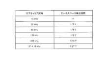
- FIG. 8 shows an example of setting the search space detection count according to the operation example 1-1 of the first embodiment.
- FIG. 9 shows another setting example of the search space detection count according to the operation example 1-1 of the first embodiment.
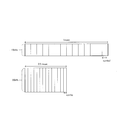
- FIG. 10A shows an arrangement example of CORESET allocated to a terminal according to another operation example of the first embodiment.
- FIG. 10B shows an arrangement example of CORESET assigned to a terminal according to another operation example of the first embodiment.
- FIG. 11A shows an example of Time first mapping.
- FIG. 11B shows an example of Frequency first mapping.
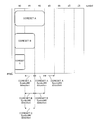
- FIG. 12 shows an example of the arrangement of CORESET assigned to the terminal according to operation example 2-1 of the second embodiment.
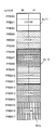
- FIG. 13A shows a setting example of the search space detection count of CORESET A according to the operation example 2-1 of the second embodiment.
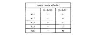
- FIG. 13B shows a setting example of the search space detection count of CORESET B according to the operation example 2-1 of the second embodiment.
- FIG. 13C shows a setting example of the search space detection count of CORESET C according to the operation example 2-1 of the second embodiment.
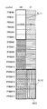
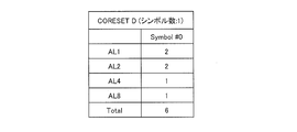
- FIG. 14A shows a setting example of the search space detection count of CORESET D according to the operation example 2-1 of the second embodiment.
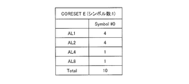
- FIG. 14B shows a setting example of the search space detection count of CORESET E according to the operation example 2-1 of the second embodiment.
- FIG. 15 shows an arrangement example of CORESET assigned to a terminal according to operation example 2-2 of the second embodiment.
- FIG. 16 shows an example of setting the number of CORESET search space detections according to the operation example 2-2 of the second embodiment.
- FIG. 17 shows another setting example of the number of CORESET search space detection times according to the operation example 2-2 of the second embodiment.
- FIG. 18 shows another setting example of the number of CORESET search space detections according to the operation example 2-2 of the second embodiment.
- PDCCH and EPDCCH are used as channels for carrying downlink control signals (DCI).
- DCI downlink control signals
- the number of symbols in which PDCCH or EPDCCH is arranged is constant.
- EPDCCH is set to detect two EPDCCH ⁇ PRB sets (corresponding to CORESET in NR)
- the symbols of the two EPDCCH PRB sets exist up to the final symbol of the subframe. Therefore, the time at which search space detection (also called blind decoding (Blind decoding)) can be started for the two EPDCCH PRB sets is the same.
- the search space of the UE is set. However, the same number of search space detections is set per DCI format for any UE.
- the search space detection capability (number of detections) may be different for each UE or for each CORESET.
- the search space detection capability cannot be used depending on the UE, or it exceeds the search space detection capability of the UE. There is a problem that the number of times of detection is set.
- the communication system includes a base station 100 (gNB) and a terminal 200 (UE).
- gNB base station 100
- UE terminal 200
- FIG. 1 is a block diagram illustrating a partial configuration of the base station 100 according to the embodiment of the present disclosure.
- detection count setting section 102 sets at least one search space including a plurality of control channel candidates to be detected by control signal (DCI) in terminal 200, and transmitting section 108 Then, a control signal mapped to any of a plurality of control channel candidates in the search space is transmitted.
- DCI control signal
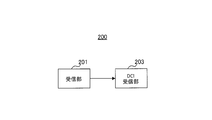
- FIG. 2 is a block diagram illustrating a partial configuration of the terminal 200 according to the embodiment of the present disclosure.
- receiving section 201 receives a signal
- DCI receiving section 203 detects at least one search space including a plurality of control channel candidates for which a control signal is to be detected in terminal 200. Then, the control signal addressed to itself is identified from the signal.
- the number of search space detections by the terminal 200 is determined based on the setting of the terminal 200.
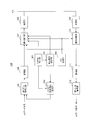
- FIG. 3 is a block diagram showing a configuration of base station 100 according to the present embodiment.
- the base station 100 includes a CORESET setting unit 101, a detection number setting unit 102, a CORESET setting information generation unit 103, a DCI generation unit 104, an error correction coding unit 105, a modulation unit 106, a signal An allocation unit 107, a transmission unit 108, a reception unit 109, a signal separation unit 110, a demodulation unit 111, and an error correction decoding unit 112 are included.
- CORESET setting section 101 sets at least one CORESET for each terminal 200 (UE), and outputs information indicating the set CORESET to detection count setting section 102, CORESET setting information generation section 103, and signal allocation section 107.
- the setting (definition) of CORESET includes, for example, a PRB (Physical Resource Block) number where each CORESET is arranged, a symbol number, the number of symbols, presence / absence of interleaving, an ID used for scrambling of CORESET, and the like.
- PRB Physical Resource Block
- the detection count setting unit 102 sets at least one search space (detection count) including a plurality of NR-PDCCH candidates for which the terminal 200 detects a control signal (DCI). Specifically, the number-of-detections setting unit 102 per symbol is based on CORESET information input from the CORESET setting unit 101 and information (not shown) indicating a slot or symbol configuration in which the CORESET is arranged. Set the maximum number of search spaces and the maximum number of search spaces detected per component carrier (cell), or the number of search spaces detected per CORESET. For example, the detection count setting unit 102 sets a large search space detection count when the slot or symbol configuration time interval is long, and sets a search space detection count low when the slot or symbol configuration time interval is short. . The detection number setting unit 102 outputs information indicating the set number of detections to the CORESET setting information generation unit 103 and the signal allocation unit 107.
- the CORESET setting information generation unit 103 uses the CORESET information input from the CORESET setting unit 101 and the information indicating the number of detection times of the search space input from the detection number setting unit 102, so that the upper layer for CORESET setting Signaling (CORESET setting information) is generated and output to the error correction encoding unit 105.
- the DCI generation unit 104 generates a control signal (DCI) including resource allocation information (DL allocation information or UL allocation information) indicating a resource to which a DL (Downlink) data signal or UL (Uplink) data signal is allocated, and DCI (DL (Allocation information and UL allocation information) are output to the signal allocation unit 107. Further, DCI generation section 104 outputs DL allocation information to the signal allocation section 107 among the generated control signals, and outputs UL allocation information to signal separation section 110.
- DCI control signal
- Error correction coding section 105 performs error correction coding on the transmission data signal (DL data signal) and higher layer signaling (CORESET setting information) input from CORESET setting information generating section 103, and modulates the encoded signal. To the unit 106.
- the modulation unit 106 performs modulation processing on the signal received from the error correction coding unit 105 and outputs the modulated signal to the signal allocation unit 107.
- the signal allocation unit 107 allocates a signal (DL data signal, CORESET setting information) received from the modulation unit 106 to the downlink resource based on the DL allocation information input from the DCI generation unit 104.
- the signal allocation unit 107 allocates the DCI input from the DCI generation unit 104 to a resource (CORESET).
- the signal allocation unit 107 determines a resource to which the DCI is allocated based on the CORESET setting information input from the CORESET setting unit 101. For example, the signal allocating unit 107 performs mapping from REG (Resource Element Group) to CCE (Control Channel Element) and search from CCE according to the number of CORESET symbols included in the information input from CORESET setting unit 101. Change the mapping to space.
- REG Resource Element Group
- CCE Control Channel Element
- the signal allocation unit 107 determines an NR-PDCCH candidate in CORESET based on the number of detections input from the detection number setting unit 102, and determines a resource to which a DCI is allocated from the NR-PDCCH candidates. In this way, a transmission signal including DCI mapped to any of the NR-PDCCH candidates is formed. The formed transmission signal is output to transmission section 108.
- the transmission unit 108 performs radio transmission processing such as up-conversion on the transmission signal input from the signal allocation unit 107 and transmits the transmission signal to the terminal 200 via the antenna.
- the reception unit 109 receives a signal transmitted from the terminal 200 via an antenna, performs wireless reception processing such as down-conversion on the received signal, and outputs the signal to the signal separation unit 110.
- the signal separation unit 110 separates the UL data signal from the reception signal received from the reception unit 109 based on the UL allocation information input from the DCI generation unit 104 and outputs the UL data signal to the demodulation unit 111.
- the demodulator 111 performs demodulation processing on the signal input from the signal separator 110 and outputs the obtained signal to the error correction decoder 112.
- the error correction decoding unit 112 decodes the signal input from the demodulation unit 111 and obtains a reception data signal (UL data signal) from the terminal 200.
- FIG. 4 is a block diagram showing a configuration of terminal 200 according to the present embodiment.
- a terminal 200 includes a receiving unit 201, a signal separating unit 202, a DCI receiving unit 203, a demodulating unit 204, an error correction decoding unit 205, a CORESET setting information receiving unit 206, and a detection number setting unit 207.
- the reception unit 201 performs reception processing such as down-conversion on the reception signal received via the antenna, and then outputs the received signal to the signal separation unit 202.
- the received signal includes, for example, a DL data signal or higher layer signaling (including CORESET setting information).
- the signal separation unit 202 separates a signal arranged in a resource to which higher layer signaling including CORESET setting information may be assigned from the reception signal received from the reception unit 201, and outputs the separated signal to the demodulation unit 204.
- the signal separation unit 202 identifies a resource corresponding to the CORESET to be monitored by the own device (CORESET to be separated) based on information input from the CORESET setting information reception unit 206, and is arranged in the resource. Separate the signal. Specifically, the signal separation unit 202 changes the resource (signal) to be separated according to the number of CORESET symbols included in the information input from the CORESET setting information reception unit 206. Further, the signal separation unit 202 identifies an NR-PDCCH candidate in CORESET based on the number of search space detections input from the detection number setting unit 207, and is a NR-PDCCH candidate (search space for the terminal 200). The signal arranged in the resource is output to the DCI receiving unit 203.
- the signal separation unit 202 separates the DL data signal from the received signal based on the DL allocation information input from the DCI reception unit 203 and outputs the DL data signal to the demodulation unit 204.
- DCI receiving section 203 detects (monitors, blind decoding) a signal (a signal arranged in a resource that is an NR-PDCCH candidate (search space)) input from signal separating section 202, and determines a DCI addressed to itself. Identify and decode (receive). DCI receiving section 203 outputs UL allocation information indicated by the received DCI to signal allocation section 210 and outputs DL allocation information to signal separation section 202.
- the demodulator 204 demodulates the signal input from the signal separator 202 and outputs the demodulated signal to the error correction decoder 205.
- the error correction decoding unit 205 decodes the demodulated signal received from the demodulating unit 204, outputs the received data signal obtained, and outputs the obtained higher layer signaling to the CORESET setting information receiving unit 206.
- the CORESET setting information receiving unit 206 identifies the CORESET setting for each terminal 200 based on the CORESET setting information included in the upper layer signalline output from the error correction decoding unit 205. Then, the CORESET setting information reception unit 206 outputs the specified information to the signal separation unit 202 and the detection number setting unit 207.
- the detection number setting unit 207 is based on the maximum detection number of search spaces per symbol and the maximum number of detections of search space per component carrier (cell), or Set the search space detection count for each CORESET.
- the detection number setting unit 207 outputs information indicating the set number of detections to the signal separation unit 202.
- the error correction encoding unit 208 performs error correction encoding on the transmission data signal (UL data signal) and outputs the encoded data signal to the modulation unit 209.
- Modulation section 209 modulates the data signal input from error correction coding section 208 and outputs the modulated data signal to signal allocation section 210.
- the signal allocation unit 210 specifies a resource to which UL data is allocated based on the UL allocation information input from the DCI reception unit 203. Then, the signal allocation unit 210 allocates the data signal input from the modulation unit 209 to the identified resource, and outputs it to the transmission unit 211.
- the transmitting unit 211 performs transmission processing such as up-conversion on the signal input from the signal allocating unit 210 and transmits the signal via the antenna.
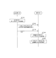
- FIG. 5 is a sequence diagram showing operations of the base station 100 and the terminal 200.
- Base station 100 performs setting of CORESET and search space (NR-PDCCH candidate) within CORESET (CORESET resource, search space detection count, etc.) for terminal 200 (ST101).
- Base station 100 transmits CORESET setting information indicating the set CORESET and search space (number of detection times) to terminal 200 using higher layer signaling (ST102).
- base station 100 places DCI (resource allocation information, etc.) in any of the search spaces in CORESET set in ST101 and transmits it to terminal 200 (ST103).
- DCI resource allocation information, etc.
- terminal 200 based on the CORESET setting information included in higher layer signaling received in ST102, terminal 200 identifies the search space (NR-PDCCH candidate) to be detected by DCI within CORESET and CORESET monitored by itself. (ST104). Terminal 200 monitors the search space in the identified CORESET and detects the DCI addressed to itself (ST105).
- search space NR-PDCCH candidate
- base station 100 determines the number of detections of search space in CORESET set in terminal 200 based on the slot or symbol configuration (time resource configuration) where CORESET (NR-PDCCH candidate) is arranged. decide.
- the time required for the detection process is expected to increase as the number of detections increases. Therefore, the upper limit value of the search space detection count varies depending on the time available for the detection process.
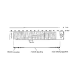
- FIG. 6 shows an example of a slot (time axis) composed of 14 symbols.
- PDCCH is arranged in symbol # 0
- PDSCH DL data
- ACK / NACK is arranged in symbol # 13.
- 6 indicate an example of the processing time of each process of PDCCH detection (PDCCH detection), PDSCH decoding (PDSCH decoding), and ACK / NACK generation (ACK / NACK preparation).
- Terminal 200 secures time to decode PDSCH, generates an ACK / NACK signal from the PDSCH reception result, and ends the PDCCH detection process so that the ACK signal or NACK signal can be transmitted with symbol # 13.
- the number of search space detections needs to be the number of times that detection is possible within this PDCCH detection processing time.
- the base station 100 sets a large number of search space detections when the slot or symbol configuration time interval is long, and sets a small search space detection number when the slot or symbol configuration time interval is short.
- the terminal 200 can complete the detection of DCI within the time by reducing the number of detections. it can.
- the search space detection count is the maximum detection count per symbol and the maximum detection count per component carrier (cell), or the detection count per CORESET.
- the maximum number of detections per symbol and the maximum number of detections per component carrier (cell) are the total values of the detection times per symbol of a plurality of CORESETs, particularly when a plurality of CORESETs are assigned to the terminal 200. Is a value determined so as not to exceed the maximum value.
- the number of times of detection per CORESET is used when the number of times of detection is specified in particular in common search space or group common search space. In either case, the following operation example can be applied.
- base station 100 determines the number of search space detections based on the subcarrier spacing (SCS) set in terminal 200. That is, in the operation example 1-1, a subcarrier spacing (SCS), that is, a time per symbol is used as a parameter indicating a slot or symbol configuration.
- SCS subcarrier spacing
- a plurality of intervals satisfying 2 m * 15 kHz are considered as subcarrier intervals.
- the subcarrier interval is 15 kHz, 30 kHz, 60 kHz, 120 kHz, 240 kHz, or the like.
- the time per symbol decreases.
- the symbol length at 30 kHz intervals is half the symbol length at 15 kHz intervals.
- there is a symbol that is 16 T s (T s 1 / (15000 ⁇ 2048) second) longer than other symbols every 0.5 m second. It is not exactly half the length.
- the base station 100 sets a larger number of search space detections as the subcarrier interval set for the terminal 200 is narrower (that is, the time per symbol is longer), and the subcarrier interval is smaller.
- the wider the search space is set that is, the shorter the time per symbol is), the smaller the number of search space detections is set. This is because even if the number of symbols that can be used for detecting the search space is the same, the wider the subcarrier interval, the shorter the time per symbol and the shorter the absolute time that can be used for detecting the search space.
- base station 100 uses the number of search space detections when the subcarrier interval is 15 kH as a reference (Y times), and sets the number of search space detections for other subcarrier intervals as subcarriers. You may set so that it may become the inverse proportion of a space
- the base station 100 can set the number of search space detections in proportion to the absolute time of the slot or symbol. For example, the base station 100 can set a larger number of search space detections as the symbol absolute time is longer.
- the correspondence relationship between the subcarrier interval (absolute time of symbols) and the number of search space detections is not limited to the example shown in FIG. 8.
- the base station 100 is completely inversely proportional as shown in FIG. 9.
- the number of search spaces may be set to be reduced step by step as the subcarrier interval becomes wider.
- base station 100 may set the number of search space detections based on the frequency band set for terminal 200. For example, the base station 100 may set the search space detection count to be smaller as the frequency band is higher.
- base station 100 determines the number of search space detections based on the number of symbols constituting the slot set in terminal 200. That is, in the operation example 1-2, the number of symbols in the slot is used as a parameter indicating the slot or symbol configuration.
- a slot is a unit of time including one or more symbols.
- the slot configuration indicates, for example, a 14 symbol slot, a 7 symbol slot, a minislot, and the like.
- a slot of 14 symbols or a slot of 7 symbols is considered when the subcarrier interval is 60 kHz or less, and a slot of 14 symbols is considered when the subcarrier interval is wider than 60 kHz.
- Mini-slots are used in systems that are sensitive to delay, such as URLLC, when there are restrictions on allocation of time resources such as unlicensed band, or when multiplexing data from multiple terminals (UE) in TDM (Time Division Multiplexing) It is assumed that
- the number of symbols in the mini-slot is less than 7 symbols.
- the time available for detecting the search space becomes shorter in the order of 14-symbol slot, 7-symbol slot, and mini-slot. This is because the shorter the number of symbols in the slot, the shorter the time that can be used for PDSCH decoding in terminal 200.
- the time available for decoding PDSCH in terminal 200 is long, even if it takes time to detect the search space, it is possible to secure the PDSCH decoding time by decoding PDSCH at high speed.
- the base station 100 sets the number of search space detections more in the 14 symbol slot than in the 7 symbol slot and the minislot, and in the 7 symbol slot, the search is performed more than in the minislot.
- Set a large number of space detections That is, base station 100 sets a large number of search space detections in the order of a mini-slot, a 7-symbol slot, and a 14-symbol slot.
- the base station 100 has a sufficient time for decoding the PDSCH, so that the number of search space detections can be set large.
- the number of search space detections can be set large.
- data of a plurality of UEs are allocated at the same time. Therefore, by increasing the number of search space detections, the probability of collision of search spaces between UEs can be reduced.
- the base station 100 sets a small number of search space detections because there is no time for PDSCH decoding.
- the number of UEs allocated at the same time is small compared to the slot of 14 symbols, and the search space collision probability between UEs is not high. Therefore, even if the number of search space detections for 7 symbols or minislots is set to be small, the influence on search space collision between UEs is small. Further, by setting the number of search space detections to be small, the complexity of processing in terminal 200 can be reduced, and the power consumption of terminal 200 can be suppressed.
- the slot format such as 14 symbol slot, 7 symbol slot, mini-slot, etc. may be notified to terminal 200 by SIB1 included in PBCH (Physical Broadcast Channel), and terminal 200 determines during RACH procedure. It may be possible to be notified by UE-specific higher layer signaling (RRC (Radio Resource Control) signaling), or may be set simultaneously when setting CORESET used for DCI allocation.
- RRC Radio Resource Control
- the slot format when the slot format is distinguished by SIB1 or RACH procedure, the slot format is not changed frequently, and reception in the same slot format is assumed in the UE. Further, when the notification of the slot format is based on UE-specific upper layer signaling or is associated with the setting of CORESET, the slot format can be changed by higher layer signaling.
- the number of PDSCH symbols in the slot and the time interval from the last PDSCH symbol to ACK / NACK transmission are set in advance by upper layer signaling. Has been.
- the time interval from the last symbol of PDSCH to the ACK / NACK transmission is long, there is room in the PDSCH decoding time, so the search space detection time can also be extended. Therefore, when the time interval from the final symbol of PDSCH to ACK / NACK transmission is long, base station 100 sets a large number of search space detections, and the transmission time from the final symbol of PDSCH to ACK / NACK transmission is short. In this case, the number of search space detections may be set small.
- the number of search space detections may be set based on UE capability or Category.
- UE capability” or “Category” is the performance of the UE defined by the Trans “port block size” that the UE can transmit and receive at maximum, the size of the soft buffer, the number of supported spatial multiplexing layers, and the like. For example, it can be said that a UE with a higher performance (UE capability is higher) as a UE has a larger Trans port block size, soft buffer size, and a larger number of spatially multiplexed layers.
- the base station 100 may set the search space detection count as UE capability or Category based on the UE performance with respect to decoding processing such as PRB processing, demodulation processing, and Polar code.
- the PRB process is a series of processes for extracting a desired PRB as an NR-PDCCH candidate from a received signal and performing a channel estimation process, a channel equalization process as necessary, and the like. It can be said that a UE having a higher performance per unit time of PRB processing or demodulation processing has a higher performance.
- the base station 100 may set a large number of search space detections for a high-performance UE and set a small number of search space detections for a low-performance UE.
- the search space detection process or detection time depends on the number of channel estimation processes that can be performed (also called channel estimation capability). It is expressed by the number of PRBs (or the number of CCEs composed of a plurality of PRBs) that can be implemented per unit time.
- the base station 100 sets a plurality of CORESETs by the CORESET setting unit 101 and the detection number setting unit 102 An example is shown.
- FIG. 10A shows an example in which the base station 100 sets two CORESET A and CORESET B.
- CORESET A is set with 16 PRBs out of 32 PRBs, which is the number of times the UE channel estimation process can be performed.
- 16 PRBs of 32 PRBs, which are the number of times the UE can perform channel estimation processing, are set in CORESET B.
- FIG. 10B shows an example in which the base station 100 sets three CORESET C, CORESET D, and CORESET E.
- CORESET C is set to 16 PRBs out of 32 PRBs, which is the number of times the UE channel estimation process can be performed.
- 8 PRBs are set in CORESET D and CORESET E, respectively, out of 32 PRBs, which is the number of times the UE can perform channel estimation processing.
- the base station 100 can set a plurality of CORESETs within the range of the feasible number of channel estimation processes of the specified UE.
- the case where one symbol is set to CORESET has been described.
- the present invention is not limited to this, and a plurality of symbols are set to CORESET within the range of the number of feasible UE channel estimation processes. It may be set.
- the search space detection count may be set based on the service category.
- Service categories include eMBB, URLLC, mMTC, etc.
- eMBB Ultra Mobile Broadband
- URLLC Ultra Mobile Broadband
- mMTC massive Machine Type Communication
- the mmTC is set to have a lower number of search space detections compared to eMBB in order to reduce UE performance and power consumption.
- the number of search space detections may be set based on digital beam forming, analog beam forming, and hybridhy beam forming (combination of digital beam forming and analog beam forming).
- the base station 100 sets the number of search space detections for the terminal 200 to which analog beamforming is applied to be smaller than the number of search space detections for the terminal 200 to which digital beamforming is applied.
- terminal 200 to which analog beam forming is applied has an advantage that the complexity of search space detection processing can be reduced and the power consumption of terminal 200 can be suppressed.
- base station 100 determines the number of search space detection times for terminal 200 to which hybrid beam forming is applied when digital beam forming is applied. It may be set smaller than the number of search space detections, or may be set larger than the number of search space detections when analog beamforming is applied. Thereby, it is possible to reduce the number of detections while ensuring the necessary number of search space detections for the terminal 200 to which hybrid beam forming is applied.
- base station 100 determines that terminal 200 is DCI based on the setting of terminal 200 (for example, slot or symbol configuration, UE capability or Category, service category, beamforming setting, etc.). Sets the number of times a search space (NR-PDCCH candidate) is detected.
- setting of terminal 200 for example, slot or symbol configuration, UE capability or Category, service category, beamforming setting, etc.
- the search space collision probability between UEs can be reduced by increasing the number of search space detections.
- the terminal 200 can complete the DCI detection in time by reducing the search space detection count.
- the search space can be set flexibly for each terminal 200 or for each CORESET by variably setting the search space detection count for the terminal 200 according to the setting of the terminal 200. it can. Thereby, it is possible to prevent terminal 200 from using the search space detection capability (number of detections) or setting the number of detections equal to or higher than the search space detection capability of terminal 200.
- terminal 200 can appropriately detect DCI by monitoring the search space in CORESET.
- the search space detection count is notified by higher layer signaling.
- the search space detection count can be calculated in each of the base station 100 and the terminal 200 using the same information and calculation formula between the base station 100 and the terminal 200, the higher-layer signaling of the search space detection count Notification by is not required.
- the information indicating the search space detection frequency set in the detection frequency setting unit 102 is not output to the CORESET setting information generation unit 103 but is output to the signal allocation unit 107. Is done.
- detection count setting section 207 is arranged with information input from CORESET setting information receiving section 206 and CORESET. Based on the configuration of slots or symbols (not shown), the maximum number of detections per symbol and the maximum number of detections per component carrier (cell) or the number of detections per CORESET are determined.
- terminal 200 sets the search space detection count to a large number when the slot or symbol configuration time interval is long, and sets the search space detection count to a low number when the slot or symbol configuration is short. Then, the detection count setting unit 207 outputs information indicating the set detection count to the signal separation unit 202.
- the base station and terminal according to the present embodiment have the same basic configuration as base station 100 and terminal 200 according to Embodiment 1, and will be described with reference to FIGS.
- the NR-PDCCH that is a control signal is arranged in one or a plurality of CCEs.
- the number of CCEs in which the NR-PDCCH is arranged is called “Aggregation level” (hereinafter sometimes abbreviated as “AL”).
- CCE is composed of multiple REGs.
- the number of REGs per CCE is considered to be 6.
- one symbol in PRB is considered to be REG.
- the CCE is configured by REGs arranged in a plurality of symbols (hereinafter referred to as “Time first mapping”), as shown in FIG. 11B.
- time first mapping a plurality of symbols
- Frequency first mapping a symbol arranged in the same symbol
- Frequency first mapping shown in FIG. 11B has an advantage that the number of symbols occupied by CCE is reduced and the amount of resources allocated to PDSCH is increased.
- NR-PDCCH is also considering changing the number of symbols for each CORESET when the UE is set to detect multiple CORESET search spaces.
- the number of CORESET symbols one symbol to all symbols in a slot or subframe is considered, and in particular, one to three symbols are being studied.
- the time when search space detection can be started by CORESET may be different. Therefore, if the number of search space detections for each CORESET is determined and the total number of search space detections for each CORESET is the maximum value, the search space detection capability (number of detections) cannot be used depending on the UE, or the UE There is a problem that the number of detections exceeding the detection capability is set.
- base station 100 sets the maximum number of detections per component carrier (cell) for each symbol, and the search space of each CORESET for terminal 200 is within a range not exceeding the maximum value for each symbol. Set the number of detections. At this time, for each NR-PDCCH candidate in the search space, base station 100 counts the number of search space detections in the final symbol among symbols in which the NR-PDCCH candidate is arranged.
- the maximum number of search space detections (maximum number of detections) by terminal 200 is set for each symbol in which a plurality of NR-PDCCH candidates (CORESET) are arranged.
- Base station 100 detects the maximum number of detections for each of a plurality of NR-PDCCH candidates in the CORESET search space in the final symbol among the symbols in which the NR-PDCCH candidates are arranged. Set within the number of times.
- the base station 100 notifies (sets) the number of detections for each aggregation level in each CORESET to the terminal 200 by upper layer signaling, for example, RRC signaling. In this way, the base station 100 can set the number of detections in detail for each terminal 200 and for each aggregation level.
- upper layer signaling for example, RRC signaling.
- Time first mapping As shown in FIG. 11A, it is assumed that one CCE is arranged in a plurality of symbols. Therefore, the NR-PDCCH candidates in CORESET are arranged up to the final symbol of CORESET. That is, in Time first mapping, the final symbol among the symbols in which NR-PDCCH candidates are arranged is the final symbol in which CORESET is arranged.
- the base station 100 counts the number of search space detections in the final symbol of each CORESET. Base station 100 then sets the number of COSPACE search space detections for terminal 200 within a range in which the number of detections to be counted does not exceed the maximum value for each symbol.
- FIG. 12 shows CORESET A with 3 symbols (symbols # 0 to # 2), CORESET B with 2 symbols (symbols # 0 and # 1), and 1 symbol (symbol # 0) in operation example 2-1. )
- CORESET C is assigned to the terminal 200.
- the maximum number of detections per symbol is Y.
- the terminal 200 starts the detection process in each CORESET after the reception process of the final symbol in which each CORESET is arranged. That is, in FIG. 12, terminal 200 starts detection processing after reception processing with symbol # 2 for CORESET A, starts detection processing after reception processing with symbol # 1 for CORESET B, and CORESET C On the other hand, the detection process is started after the reception process with the symbol # 0. That is, the detection start timing at the terminal 200 is different for each CORESET.
- the base station 100 sets the number of detections for each CORESET up to the maximum number of detections Y per symbol in the final symbol where each CORESET is arranged.
- base station 100 detects search space for each CORESET.
- the number of times can be set by Y times (that is, the maximum number of detection times per symbol).
- base station 100 sets the number of detections Y times for CORESET C in symbol # 0, sets the number of detections Y times for CORESET B in symbol # 1, and in symbol # 2 Set the number of detection times Y for CORESET A. That is, the base station 100 sets the maximum number of detections (3Y times) in symbols # 0 to # 2 in which CORESET A, B, and C shown in FIG. Can be assigned. In other words, in FIG. 12, it is not necessary to distribute the maximum number of detections (Y times) for each symbol among the CORESETs for different numbers of CORESETs.
- the base station 100 sets the number of search spaces for each aggregation level for each CORESET (not shown).
- the base station 100 notifies the terminal 200 of the number of search space detections for each CORESET and for each aggregation level using upper layer signaling.
- each CORESET is arranged.
- the number of detections of each aggregation level may be notified so that the maximum number of detections (Y times) for each symbol is not exceeded.
- the maximum number of detections Y for each symbol is 16 times.
- each CORESET is assigned a detection count of 16 times in different symbols.
- the number of detections for each aggregation level may differ depending on each CORESET.
- base station 100 assigns the detection counts of the plurality of CORESETs so as not to exceed the maximum detection count (Y times) for each symbol. Just do it.
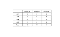
- FIG. 14A and FIG. 14B show an example of assigning the number of detection times when two CORESETs (CORESET D, CORESET E) with the number of symbols 1 are assigned to the terminal 200.
- the maximum number of detections per symbol is 16.
- the total number of detections of CORESETCOD is 6 as shown in FIG. 14A
- the total number of detections of CORESET E is 10 as shown in FIG. 14B
- the total number of detections in symbol # 0 is 16. ing.
- the number of search space detections for a plurality of CORESETs with the same number of symbols may be different for each CORESET as shown in FIGS. 14A and 14B, or may be an equal value (the same value) between CORESETs.
- the base station 100 sets the number of detections in each CORESET so that the maximum number of detections does not exceed the maximum value per symbol between CORESETs having the same symbol length. This eliminates the need to share the number of search space detections between CORESETs having different numbers of symbols. Therefore, by assigning CORESET with a different number of symbols to terminal 200, the number of search space detections at terminal 200 can be increased, and the search space collision probability between UEs can be reduced.
- the NR-PDCCH candidates may not use all symbols in CORESET but use some symbols.
- the base station 100 may count the number of detections of the NR-PDCCH candidate in the final symbol in which the NR-PDCCH candidate is arranged instead of the final symbol of CORESET. That is, base station 100 may count the number of detections in each of a plurality of symbols in CORESET.
- the base station 100 counts the number of search space detections related to the NR-PDCCH candidate in the final symbol among the symbols in which the NR-PDCCH candidates in each CORESET are arranged. Base station 100 then sets the number of search space detections for each NR-PDCCH candidate for terminal 200 within a range in which the number of detections to be counted does not exceed the maximum value for each symbol.
- FIG. 15 shows CORESET A with the number of symbols 3 (symbols # 0 to # 2), CORESET B with the number of symbols 2 (symbols # 0 and # 1), and the number of symbols 1 (symbol # 0) in the operation example 2-2. )
- CORESET C is assigned to the terminal 200.
- the maximum number of detections per symbol is Y.
- terminal 200 starts detection of the NR-PDCCH candidate after receiving the final symbol in which the NR-PDCCH candidate is arranged in each CORESET. Therefore, depending on the arrangement of NR-PDCCH in CORESET, terminal 200 can start the detection process without waiting for reception of the final symbol in which CORESET is arranged.
- CORESET A with three symbols shown in FIG. 15, NR-PDCCH candidates arranged only in symbol # 0 and NR-PDCCH candidates arranged only in symbol # 0, # 1 or symbol # 1 (symbol NR-PDCCH candidate with # 1 as the final symbol) and NR-PDCCH candidate placed only in symbol # 0, # 1, # 2 or symbol # 2 (NR-PDCCH candidate with symbol # 2 as the final symbol) Are included.
- CORESET ⁇ B with two symbols shown in FIG. 15 NR-PDCCH candidates arranged only in symbol # 0 and NR-PDCCH candidates arranged only in symbol # 0, # 1 or symbol # 1 ( NR-PDCCH candidates with symbol # 1 as the final symbol).
- CORESET ⁇ C having one symbol as shown in FIG. 15 includes NR-PDCCH candidates arranged only in symbol # 0.
- the terminal 200 starts detection when each NR-PDCCH candidate is received in each symbol.
- the operation example 2-2 when a plurality of CORESETs having different numbers of symbols are allocated to the terminal 200, in each symbol where each CORESET is arranged, up to the maximum number of detections per symbol (Y times), The number of detections can be assigned to each NR-PDCCH candidate of CORESET. For example, in FIG. 15, the base station 100 does not exceed the maximum number of detections (Y times) for the NR-PDCCH candidate having the symbol # 0 in CORESET A, B, and C as the final symbol in symbol # 0. The number of detections is set for each.
- base station 100 sets the number of detections so as not to exceed the maximum number of detections (Y times) for the NR-PDCCH candidate whose final symbol is symbol # 1 in CORESET A and B in symbol # 1. Set. Also, base station 100 sets the number of detections so as not to exceed the maximum number of detections (Y times) for the NR-PDCCH candidate whose final symbol is symbol # 2 in CORESET A in symbol # 2.
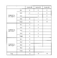
- the base station 100 notifies the terminal 200 of the number of search space detections for each CORESET, for each symbol, and for each aggregation level, using higher layer signaling.
- the number of detections of NR-PDCCH candidates for CORESET A (the total number of detections of each Aggregation level) is set to 5
- the number of detections of NR-PDCCH candidates for CORESET B ( The total number of times of detection of each aggregation level) is set to five times
- the number of detections of NR-PDCCH candidates for CORESET C (the total number of detection times of each aggregation level) is set to six times. The same applies to other symbols.
- the NR-PDCCH candidate detected by symbol # 1 is arranged only at symbol # 0, # 1, or symbol # 1. Therefore, the number of detections may be set by distinguishing the number of symbols in which the NR-PDCCH candidates are arranged, and the number of detections may be notified in a higher layer.
- FIG. 17 shows an example in which the number of detections is set by distinguishing the number of symbols in which NR-PDCCH candidates are arranged.
- the number of detections is set separately for the case where the NR-PDCCH candidate is arranged in only one symbol and the case where the NR-PDCCH candidate is arranged in a plurality of symbols. Has been.
- the base station 100 allocates a signal using NR-PDCCH candidates that straddle multiple symbols and wants to time multiplex with other UEs.
- the NR-PDCCH candidates can be selectively used according to the usage, such as assigning signals using NR-PDCCH candidates arranged only in one symbol.
- the number of detections of NR-PDCCH candidates for Aggregation level detected in each symbol may be set equal. In this way, it is possible to reduce the overhead of upper layer signaling.
- base station 100 sets each NR-PDCCH in the last symbol for each NR-PDCCH candidate in the search space when setting the number of detections of CORESET set in terminal 200. Count the number of detections for a candidate. Further, the maximum number of detections per component carrier (cell) is set for each symbol. Then, the base station 100 sets the number of detections for each symbol within a range not exceeding the maximum number of detections for each symbol.
- the total number of search space detections for the terminal 200 can be increased. Thereby, the collision probability of the search space between UEs can be reduced.
- base station 100 sets the number of detections for each CORESET and for each aggregation level by upper layer signaling (for example, RRC signaling). Thereby, a fine setting of the number of detections is possible for each terminal 200 and for each aggregation level.
- upper layer signaling for example, RRC signaling
- the number of detections for each CORESET may be counted with the final symbol of CORESET in both Frequency first mapping and Time first mapping.
- the base station 100 may set the number of detections separately for CORESETs having different numbers of symbols, and the setting of the number of detections is simplified.
- the number of detections in each symbol may be set to be equal to or less than the maximum number of detections, and the total number of detections notified by higher layer signaling may be less than the maximum number of detections.
- the method described in the first embodiment can be applied as a method for setting the maximum number of detection times (Y times).
- Aggregation level is 1, 2, 4, 8
- the number of detections may be counted every two symbols or every Z symbols.
- the method of counting the number of detections for each Z symbol is suitable, for example, when the terminal 200 performs a process of starting search space detection after receiving the Z symbol.
- the processing can be simplified by performing such processing.
- DMRS Demodulation Reference Signal
- terminal 200 when a reference signal (DMRS: Demodulation Reference Signal) is used in common between NR-PDCCH candidates on the time axis, terminal 200 must perform demodulation processing of NR-PDCCH if estimation processing using DMRS is not completed. Can not do. Therefore, when there is a DMRS that must be referred to in the rear symbol rather than the final symbol of the symbol in which the NR-PDCCH is arranged, the base station 100 detects the number of detections of the NR-PDCCH at the DMRS symbol position. May be counted. Note that whether or not DMRS is used for estimation processing with symbols behind NR-PDCCH may be set simultaneously with the setting of CORESET.
- the number of symbols 1, 2, and 3 has been studied as the number of symbols for CORESET, it may be assigned to consecutive symbols as a CORESET arrangement in the slot. For example, when the number of symbols of CORESET is 3, CORESET is arranged at the front symbols # 0, # 1, # 2 in the slot. Also, the number of CORESET symbols supported varies depending on the bandwidth. For example, if the bandwidth is less than X, CORESET is supported with 3 or less symbols (i.e., 1, 2 or 3 symbols), and if the bandwidth is X or more, 2 or less symbols (i.e. 1, 2 symbols) CORESET is supported.
- the number of symbols supported by the slot configuration may be limited. For example, 14 symbol slots may support 1, 2 and 3 as the number of CORESET symbols, and 7 symbol slots may support 1 and 2 as the number of CORESET symbols. In this way, it is possible to prevent the number of CORESET symbols from increasing in seven symbol slots with a small number of symbols, and the number of symbols on which PDSCH and PUSCH can be arranged from decreasing.
- the DMRS arrangement position may be determined from the longest number of CORESET symbols determined from the bandwidth and the slot configuration (14 symbols or 7 symbols). For example, when the longest number of CORESET symbols is 3, the DMRS for PDSCH may be arranged in the fourth symbol, and when the longest CORESET symbol is 2, the DMRS for PDSCH may be arranged in the third symbol. In this way, the position of the DMRS for PDSCH can be fixedly set ahead of the symbols that do not overlap with the CORESET symbols, regardless of the CORESET symbol length that is actually assigned. Disposing DMRS in the front of the slot has an advantage that terminal 200 can finish channel estimation at an early stage and advance the start time of PDSCH decoding processing.
- the base station and terminal according to the present embodiment have the same basic configuration as base station 100 and terminal 200 according to Embodiment 1, and will be described with reference to FIGS.
- the base station 100 and the terminal 200 use the information shared between the base station 100 and the terminal 200 and the prescribed calculation formula for the number of times of detection space aggregation level detection for the terminal 200. Determine based on. In this way, the number of RRC signaling can be reduced as compared with the second embodiment.
- the maximum value Y per component carrier (cell) of the search space detection count is predetermined in the same manner as in the second embodiment.
- the maximum value Y may be determined by the same method as in the first embodiment.
- the base station 100 and the terminal 200 have the same number of REGs and CCEs included in each CORESET.
- the number of detections is evenly distributed, and when the number of REGs and the number of CCEs are different, a large number of detections are distributed to a larger size CORESET. By doing so, it is possible to reduce the search space collision probability between UEs in a resource in which a larger size CORESET is arranged.
- the method of Operation Example 3-1 is particularly suitable for Time first mapping.
- Time first mapping terminal 200 may start detecting all NR-PDCCH candidates after the reception processing of the final symbol of CORESET. Therefore, in the operation example 3-1, it is effective to allocate more detection times so that the probability of collision of search spaces between UEs becomes lower as the size of CORESET is larger.
- the base station 100 and the terminal 200 may assign more detection counts to CORESET having a large number of PRBs to be configured. In this way, a large number of detections can be assigned to CORESET with a large number of PRBs per symbol. This method is particularly suitable for frequency first mapping in which search space is detected for each symbol.
- CORESET # 0 is assigned to the terminal 200
- the sizes are N0 and N1, respectively.
- the maximum number of detections of the search space per symbol is Y times.
- the number of detections assigned to CORESET # 0 is obtained by Y * N0 / (N0 + N1)
- the number of detections assigned to CORESET # 1 is obtained by Y * N1 / (N0 + N1).
- the base station 100 and the terminal 200 can equally distribute the number of detections (Y / 2 times) to each CORESET when the sizes of the two CORESETs are equal.
- the base station 100 and the terminal 200 secure the number of detections for CORESET for common search space and CORESET for group common search space (that is, the number of detections of CORESET for common search space). Then, the base station 100 and the terminal 200 allocate the number of detections of CORESET for UE specific search space after securing the number of times of detection of the common search space. In this way, it is possible to preferentially secure the number of times of detection of Common search space and group common search space where important information may be transmitted.
- CORESET for Common search space can be specified by the information included in PBCH.
- the CORESET for group ⁇ common search space can be specified from information included in the SIB or specified by notifying the setting by the SIB.
- both Common search space and group common search space are set before UE specific search space is set.
- CORESET # 0 two UE-specific search space CORESETs (CORESET # 0, CORESET # 1) are allocated to the terminal 200, and the sizes (here, the number of REGs per CORESET) are N0 and N1, respectively.
- the maximum number of detections is Y.
- the number of detections assigned to CORESET for Common ⁇ search space is Nc.
- the number of detections assigned to CORESET # 0 is determined by (Y-Nc) * N0 / (N0 + N1)
- the number of detections assigned to CORESET # 1 is (Y-Nc) * N1 / (N0 + N1) ).
- the Aggregation level used is variable according to the bandwidth. Specifically, the Aggregation level is lowered in the low band, and the Aggregation level is increased in the high band.
- the supported Aggregation level may be different between a band lower than 6 GHz (below 6 GHz) and a band higher than 6 GHz (above 6 GHz).
- the aggregation level used is variable according to the subcarrier interval. Specifically, Aggregation ⁇ ⁇ level is lowered at narrow subcarrier intervals, and Aggregation level is raised at wide subcarrier intervals.
- Aggregation level to be used is set according to UE capability or Category.
- UE capability or “Category” refers to the UE performance defined by the Trans “port block size” that the UE can transmit and receive at maximum, the size of the soft buffer, the number of supported spatial multiplexing layers, and the like.
- the UE with higher performance may be able to improve the line quality due to the effect of antenna diversity. Therefore, it is effective to assign a lower Aggregation level to a UE having higher performance and to assign a higher Aggregation level to a UE having lower performance.
- the base station 100 may set the aggregation level as the UE capability or Category based on the UE performance with respect to decoding processing such as PRB processing, demodulation processing, and Polar code.
- the PRB process is a series of processes for extracting a desired PRB as an NR-PDCCH candidate from a received signal and performing a channel estimation process, a channel equalization process as necessary, and the like. It can be said that a UE having a higher performance per unit time of PRB processing or demodulation processing has a higher performance. The UE with higher performance may be able to improve the line quality due to the effect of antenna diversity.
- a UE with a higher number of implementations per unit time of PRB processing or demodulation processing is assigned a lower aggregation level, and a UE with a lower number of implementations of PRB processing or demodulation processing per unit time is higher with higher aggregation. It is effective to assign a level.
- Aggregation level to be used is set according to the service category.
- Service categories include eMBB, URLLC, mMTC, etc. Since ULRRC is tolerant of delay, the error rate required for DCI is higher than other service categories. Therefore, URLLC can use a higher aggregation level than eMBB. In eMTC, there is a possibility of being placed in a place where the line quality is poor. In that case, it is possible to improve reception quality by using a high aggregation level.
- the base station 100 and the terminal 200 determine the number of detections for each aggregation level of the search space set in the terminal 200 according to the information to be shared and the prescribed calculation formula. By so doing, it is possible to reduce the amount of signaling (for example, RRC signaling) from the base station 100 to the terminal 200 regarding the setting of the search space.
- RRC signaling for example, RRC signaling
- the search space detection frequency is set for each component carrier.
- the search space detection frequency may be common to all the component carriers or may be different for each component carrier.
- the physical mapping has been described as an example for the frequency domain (PRB #), but it can also be applied to logical mapping.
- PRB # frequency domain
- logical mapping since the logical mapping is changed to the physical mapping, even if the frequency domain is continuous in the logical mapping, it is physically located at a distant position. A frequency diversity effect can be obtained.
- control resource set (CORESET) is sometimes called search space or PDCCH PRB set.
- CORESETs can be assigned to the UE.
- the case where the CORESET head symbol is symbol # 0 (slot head symbol) has been described as an example.
- CORESET may be arranged from the symbol behind the slot.
- higher layer signaling may be replaced with MAC signaling.
- MAC signaling compared to RRC signaling, the frequency of changing the case set in the UE can be increased.
- the DMRS may be a reference signal (Reference signal) with a different name.
- Each functional block used in the description of the above embodiment is partially or entirely realized as an LSI that is an integrated circuit, and each process described in the above embodiment may be partially or entirely performed. It may be controlled by one LSI or a combination of LSIs.
- the LSI may be composed of individual chips, or may be composed of one chip so as to include a part or all of the functional blocks.
- the LSI may include data input and output.
- An LSI may be referred to as an IC, a system LSI, a super LSI, or an ultra LSI depending on the degree of integration.
- the method of circuit integration is not limited to LSI, and may be realized by a dedicated circuit, a general-purpose processor, or a dedicated processor.
- an FPGA Field Programmable Gate Array
- a reconfigurable processor that can reconfigure the connection and setting of circuit cells inside the LSI may be used.
- the present disclosure may be implemented as digital processing or analog processing.
- integrated circuit technology comes out to replace LSI's as a result of the advancement of semiconductor technology or a derivative other technology, it is naturally also possible to carry out function block integration using this technology. Biotechnology can be applied.
- the base station includes a circuit that sets at least one search space including a plurality of control channel candidates for which a control signal is detected in a terminal, and any one of the plurality of control channel candidates in the search space.
- a transmitter for transmitting the mapped control signal, and the number of times the search space is detected by the terminal is determined based on the setting of the terminal.
- the number of times that the search space is detected is determined based on a configuration of time resources in which the control channel candidates are arranged.
- the parameter indicating the configuration of the time resource is the number of symbols constituting the slot or the time per symbol.
- the number of detections of the search space is determined based on the subcarrier interval set in the terminal.
- the number of times the search space is detected is determined based on a service category set in the terminal or a category of the terminal.
- the base station includes a circuit that sets at least one search space including a plurality of control channel candidates for which a control signal is detected in a terminal, and any one of the plurality of control channel candidates in the search space.
- the number of detections for each aggregation level of each of the at least one search space is notified to the terminal by higher layer signaling.
- the number of detections for each aggregation level of each of the at least one search space is determined based on information shared between the base station and the terminal.
- the terminal of the present disclosure detects at least one search space including a receiver that receives a signal and a plurality of control channel candidates that are targets for detecting a control signal in the terminal, and the control addressed to the terminal is detected from the signal A circuit for specifying a signal, and the number of times the terminal detects the search space is determined based on a setting of the terminal.
- the terminal of the present disclosure detects at least one search space including a receiver that receives a signal and a plurality of control channel candidates that are targets for detecting a control signal in the terminal, and the control addressed to the terminal is detected from the signal And a circuit for identifying a signal, wherein a maximum value of the number of times the search space is detected by a terminal is set for each symbol in which the plurality of control channel candidates are arranged, and each of the plurality of control channel candidates is The number of detections is set within the maximum value in the last symbol among the symbols in which the control channel candidates are arranged.
- At least one search space including a plurality of control channel candidates to be detected by a terminal at a terminal is set, and mapped to any of the plurality of control channel candidates in the search space.
- the control signal is transmitted, and the number of times the terminal detects the search space is determined based on the setting of the terminal.
- At least one search space including a plurality of control channel candidates to be detected by a terminal at a terminal is set, and mapped to any of the plurality of control channel candidates in the search space.
- a maximum value of the number of detections of the search space by the terminal is set for each symbol in which the plurality of control channel candidates are arranged, and the number of detections for each of the plurality of control channel candidates Is set within the maximum value in the last symbol among the symbols in which the control channel candidates are arranged.
- a signal is received, and at least one search space including a plurality of control channel candidates to be detected by the terminal is detected, and the control signal addressed to the own device is detected from the signal.
- the number of times the search space is detected by the terminal is determined based on a setting of the terminal.
- the communication method of the present disclosure detects a control signal addressed to the terminal from the signal by detecting at least one search space including a plurality of control channel candidates for receiving a signal and detecting a control signal in the terminal.
- a maximum value of the number of detections of the search space by the terminal is set for each symbol in which the plurality of control channel candidates are arranged, and the number of detections for each of the plurality of control channel candidates is determined by the control channel Among the symbols in which candidates are arranged, the final symbol is set within the maximum value.
- One embodiment of the present disclosure is useful for a mobile communication system.
Landscapes
- Engineering & Computer Science (AREA)
- Signal Processing (AREA)
- Computer Networks & Wireless Communication (AREA)
- Computer Security & Cryptography (AREA)
- Mobile Radio Communication Systems (AREA)
Abstract
Description
本開示の各実施の形態に係る通信システムは、基地局100(gNB)及び端末200(UE)を備える。
[基地局の構成]
図3は、本実施の形態に係る基地局100の構成を示すブロック図である。図3において、基地局100は、CORESET設定部101と、検出回数設定部102と、CORESET設定情報生成部103と、DCI生成部104と、誤り訂正符号化部105と、変調部106と、信号割当部107と、送信部108と、受信部109と、信号分離部110と、復調部111と、誤り訂正復号部112とを有する。
図4は、本実施の形態に係る端末200の構成を示すブロック図である。図4において、端末200は、受信部201と、信号分離部202と、DCI受信部203と、復調部204と、誤り訂正復号部205と、CORESET設定情報受信部206と、検出回数設定部207と、誤り訂正符号化部208と、変調部209と、信号割当部210と、送信部211と、を有する。
以上の構成を有する基地局100及び端末200における動作について詳細に説明する。
動作例1-1では、基地局100は、端末200に設定されるサブキャリア間隔(SCS:Subcarrier spacing)に基づいて、サーチスペースの検出回数を決定する。すなわち、動作例1-1では、スロット又はシンボル構成を示すパラメータとして、サブキャリア間隔(SCS:Subcarrier spacing)、つまり、シンボルあたりの時間を用いる。
動作例1-2では、基地局100は、端末200に設定されるスロットを構成するシンボル数に基づいて、サーチスペースの検出回数を決定する。すなわち、動作例1-2では、スロット又はシンボル構成を示すパラメータとして、スロット内のシンボル数を用いる。
(1)サーチスペース検出回数は、UE capability又はCategoryに基づいて設定されてもよい。
本実施の形態に係る基地局及び端末は、実施の形態1に係る基地局100及び端末200と基本構成が共通するので、図3及び図4を援用して説明する。
制御信号であるNR-PDCCHは、1つ又は複数のCCEに配置される。NR-PDCCHが配置されるCCE数は「Aggregation level」(以下、「AL」と略すこともある)と呼ばれる。
Time first mappingでは、図11Aに示すように、1つのCCEが複数のシンボルに配置されることが想定される。よって、CORESET内のNR-PDCCH候補はCORESETの最終シンボルまで配置される。つまり、Time first mappingでは、NR-PDCCH候補が配置されるシンボルのうち最終シンボルは、CORESETが配置される最終シンボルである。
Frequency first mappingでは、図11Bに示すように、1つのCCEが1つのシンボルに配置されることが想定される。よって、CORESET内のNR-PDCCH候補はCORESET内の1シンボル、又は、複数のシンボルに配置される。
本実施の形態に係る基地局及び端末は、実施の形態1に係る基地局100及び端末200と基本構成が共通するので、図3及び図4を援用して説明する。
動作例3-1では、端末200に対して複数のCORESETが割り当てられた場合、CORESET間でのサーチスペース検出回数の分配において、CORESETに含まれるREG数及びCCE数が多いCORESETにより多くの検出回数を割り当てる。ここで、REG数及びCCE数は、CORESETのサイズの大きさを示している。
動作例3-2では、1つのCORESET内でのAggregation level毎のサーチスペース検出回数の分配は、下記の条件の1つ又は複数に従って決定される。
101 CORESET設定部
102,207 検出回数設定部
103 CORESET設定情報生成部
104 DCI生成部
105,208 誤り訂正符号化部
106,209 変調部
107,210 信号割当部
108,211 送信部
109,201 受信部
110,202 信号分離部
111,204 復調部
112,205 誤り訂正復号部
200 端末
203 DCI受信部
206 CORESET設定情報受信部
Claims (14)
- 端末において制御信号を検出する対象となる複数の制御チャネル候補を含む少なくとも1つのサーチスペースを設定する回路と、
前記サーチスペース内の前記複数の制御チャネル候補の何れかにマッピングされた前記制御信号を送信する送信機と、
を具備し、
前記端末による前記サーチスペースの検出回数は、前記端末の設定に基づいて決定される、
基地局。 - 前記サーチスペースの検出回数は、前記制御チャネル候補が配置される時間リソースの構成に基づいて決定される、
請求項1に記載の基地局。 - 前記時間リソースの構成を示すパラメータは、スロットを構成するシンボル数、又は、シンボルあたりの時間である、
請求項2に記載の基地局。 - 前記サーチスペースの検出回数は、前記端末に設定されるサブキャリア間隔に基づいて決定される、
請求項1に記載の基地局。 - 前記サーチスペースの検出回数は、前記端末に設定されるサービスカテゴリ又は前記端末のカテゴリに基づいて決定される、
請求項1に記載の基地局。 - 端末において制御信号を検出する対象となる複数の制御チャネル候補を含む少なくとも1つのサーチスペースを設定する回路と、
前記サーチスペース内の前記複数の制御チャネル候補の何れかにマッピングされた前記制御信号を送信する送信機と、
を具備し、
前記端末による前記サーチスペースの検出回数の最大値が、前記複数の制御チャネル候補が配置されるシンボル毎に設定され、
前記回路は、前記複数の制御チャネル候補の各々に対する前記検出回数を、当該制御チャネル候補が配置されるシンボルのうち最終シンボルにおいて前記最大値以内に設定する、
基地局。 - 前記少なくとも1つのサーチスペースの各々のAggregation level毎の前記検出回数は、上位レイヤのシグナリングによって前記端末へ通知される、
請求項6に記載の基地局。 - 前記少なくとも1つのサーチスペースの各々のAggregation level毎の前記検出回数は、前記基地局と前記端末との間で共有される情報に基づいて決定される、
請求項6に記載の基地局。 - 信号を受信する受信機と、
端末において制御信号を検出する対象となる複数の制御チャネル候補を含む少なくとも1つのサーチスペースを検出して、前記信号から自機宛ての前記制御信号を特定する回路と、
を具備し、
前記端末による前記サーチスペースの検出回数は、前記端末の設定に基づいて決定される、
端末。 - 信号を受信する受信機と、
端末において制御信号を検出する対象となる複数の制御チャネル候補を含む少なくとも1つのサーチスペースを検出して、前記信号から自機宛ての前記制御信号を特定する回路と、
を具備し、
前記端末による前記サーチスペースの検出回数の最大値が、前記複数の制御チャネル候補が配置されるシンボル毎に設定され、
前記複数の制御チャネル候補の各々に対する前記検出回数は、当該制御チャネル候補が配置されるシンボルのうち最終シンボルにおいて前記最大値以内に設定される、
端末。 - 端末において制御信号を検出する対象となる複数の制御チャネル候補を含む少なくとも1つのサーチスペースを設定し、
前記サーチスペース内の前記複数の制御チャネル候補の何れかにマッピングされた前記制御信号を送信し、
前記端末による前記サーチスペースの検出回数は、前記端末の設定に基づいて決定される、
通信方法。 - 端末において制御信号を検出する対象となる複数の制御チャネル候補を含む少なくとも1つのサーチスペースを設定し、
前記サーチスペース内の前記複数の制御チャネル候補の何れかにマッピングされた前記制御信号を送信し、
前記端末による前記サーチスペースの検出回数の最大値が、前記複数の制御チャネル候補が配置されるシンボル毎に設定され、
前記複数の制御チャネル候補の各々に対する前記検出回数は、当該制御チャネル候補が配置されるシンボルのうち最終シンボルにおいて前記最大値以内に設定される、
通信方法。 - 信号を受信し、
端末において制御信号を検出する対象となる複数の制御チャネル候補を含む少なくとも1つのサーチスペースを検出して、前記信号から自機宛ての前記制御信号を特定し、
前記端末による前記サーチスペースの検出回数は、前記端末の設定に基づいて決定される、
通信方法。 - 信号を受信し、
端末において制御信号を検出する対象となる複数の制御チャネル候補を含む少なくとも1つのサーチスペースを検出して、前記信号から前記端末宛ての前記制御信号を特定し、
前記端末による前記サーチスペースの検出回数の最大値が、前記複数の制御チャネル候補が配置されるシンボル毎に設定され、
前記複数の制御チャネル候補の各々に対する前記検出回数は、当該制御チャネル候補が配置されるシンボルのうち最終シンボルにおいて前記最大値以内に設定される、
通信方法。
Priority Applications (9)
| Application Number | Priority Date | Filing Date | Title |
|---|---|---|---|
| JP2019525153A JP7046942B2 (ja) | 2017-06-16 | 2018-04-17 | 端末、受信方法及び集積回路 |
| EP18816885.0A EP3641441B1 (en) | 2017-06-16 | 2018-04-17 | Base station, terminal and communication method |
| US16/615,805 US11240738B2 (en) | 2017-06-16 | 2018-04-17 | Base station, terminal, and communication method |
| CN202311145922.7A CN117528806A (zh) | 2017-06-16 | 2018-04-17 | 通信装置、用户设备及通信方法 |
| EP26158916.2A EP4723771A2 (en) | 2017-06-16 | 2018-04-17 | Base station, terminal and communication method |
| CN201880033606.1A CN110651525B (zh) | 2017-06-16 | 2018-04-17 | 终端、接收方法及集成电路 |
| US17/559,788 US12127100B2 (en) | 2017-06-16 | 2021-12-22 | Communication apparatus and method for search space settings and monitoring |
| JP2022047145A JP7280405B2 (ja) | 2017-06-16 | 2022-03-23 | 基地局、送信方法及び集積回路 |
| US18/886,766 US20250008417A1 (en) | 2017-06-16 | 2024-09-16 | Communication apparatus and method for search space settings and monitoring |
Applications Claiming Priority (4)
| Application Number | Priority Date | Filing Date | Title |
|---|---|---|---|
| JP2017118607 | 2017-06-16 | ||
| JP2017-118607 | 2017-06-16 | ||
| JP2017-153346 | 2017-08-08 | ||
| JP2017153346 | 2017-08-08 |
Related Child Applications (2)
| Application Number | Title | Priority Date | Filing Date |
|---|---|---|---|
| US16/615,805 A-371-Of-International US11240738B2 (en) | 2017-06-16 | 2018-04-17 | Base station, terminal, and communication method |
| US17/559,788 Continuation US12127100B2 (en) | 2017-06-16 | 2021-12-22 | Communication apparatus and method for search space settings and monitoring |
Publications (1)
| Publication Number | Publication Date |
|---|---|
| WO2018230139A1 true WO2018230139A1 (ja) | 2018-12-20 |
Family
ID=64658625
Family Applications (1)
| Application Number | Title | Priority Date | Filing Date |
|---|---|---|---|
| PCT/JP2018/015793 Ceased WO2018230139A1 (ja) | 2017-06-16 | 2018-04-17 | 基地局、端末及び通信方法 |
Country Status (5)
| Country | Link |
|---|---|
| US (3) | US11240738B2 (ja) |
| EP (2) | EP4723771A2 (ja) |
| JP (2) | JP7046942B2 (ja) |
| CN (2) | CN117528806A (ja) |
| WO (1) | WO2018230139A1 (ja) |
Cited By (5)
| Publication number | Priority date | Publication date | Assignee | Title |
|---|---|---|---|---|
| WO2020145320A1 (en) * | 2019-01-09 | 2020-07-16 | Sharp Kabushiki Kaisha | User equipments, base stations and methods for multiple active configurations for uplink transmission |
| WO2020157873A1 (ja) * | 2019-01-30 | 2020-08-06 | 株式会社Nttドコモ | ユーザ装置及び基地局装置 |
| WO2020157874A1 (ja) * | 2019-01-30 | 2020-08-06 | 株式会社Nttドコモ | ユーザ装置及び基地局装置 |
| WO2020250322A1 (ja) * | 2019-06-11 | 2020-12-17 | 株式会社Nttドコモ | 端末及び無線通信方法 |
| US20220039140A1 (en) * | 2020-07-28 | 2022-02-03 | Comcast Cable Communications, Llc | Control Channel Repetition Using Multiple Coresets |
Families Citing this family (12)
| Publication number | Priority date | Publication date | Assignee | Title |
|---|---|---|---|---|
| US11240738B2 (en) * | 2017-06-16 | 2022-02-01 | Panasonic Intellectual Property Corporation Of America | Base station, terminal, and communication method |
| KR101962148B1 (ko) | 2017-06-16 | 2019-03-26 | 엘지전자 주식회사 | 하향링크 채널을 송수신하는 방법 및 이를 위한 장치 |
| CN109392140B (zh) * | 2017-08-11 | 2020-07-28 | 维沃移动通信有限公司 | 一种用于监听pdcch的方法、终端及网络设备 |
| CN110690940A (zh) * | 2018-07-04 | 2020-01-14 | 北京三星通信技术研究有限公司 | 下行接收方法、用于pdcch检测的方法、ue和计算机可读介质 |
| CN110972320B (zh) * | 2018-09-30 | 2022-01-25 | 维沃移动通信有限公司 | 接收方法、发送方法、终端及网络侧设备 |
| EP3949658B1 (en) | 2019-03-27 | 2025-08-20 | InterDigital Patent Holdings, Inc. | Methods for wideband unlicensed channel access |
| CN111448821B (zh) * | 2020-03-12 | 2024-03-01 | 北京小米移动软件有限公司 | 控制信道检测、信息传输方法及装置、设备及存储介质 |
| EP4128939A4 (en) * | 2020-04-01 | 2024-02-07 | Lenovo (Beijing) Limited | METHOD AND DEVICE FOR DETERMINING A TAX EQUIPMENT RATE |
| US11671994B2 (en) * | 2020-04-10 | 2023-06-06 | Qualcomm Incorporated | Reusing PDSCH TCI and QCL for dynamic coresets |
| US11758552B2 (en) * | 2021-04-06 | 2023-09-12 | Qualcomm Incorporated | User equipment monitoring capability for multiple slot physical downlink control channel monitoring |
| CN115884405B (zh) * | 2021-09-26 | 2026-02-10 | 维沃软件技术有限公司 | 上行控制信道的传输方法、终端设备和网络设备 |
| US20230224130A1 (en) * | 2022-01-07 | 2023-07-13 | Qualcomm Incorporated | Control resource set type configurations |
Citations (3)
| Publication number | Priority date | Publication date | Assignee | Title |
|---|---|---|---|---|
| WO2013024569A1 (ja) * | 2011-08-12 | 2013-02-21 | パナソニック株式会社 | 送信装置、受信装置、送信方法、及び受信方法 |
| JP2014527339A (ja) * | 2011-07-29 | 2014-10-09 | アルカテル−ルーセント | プリコードされた物理ダウンリンク制御チャネルの参照信号およびブラインド復号のための方法および装置 |
| JP2014527348A (ja) * | 2011-08-08 | 2014-10-09 | 華為技術有限公司 | 情報検出及び情報送信方法、及び情報検出及び情報送信装置 |
Family Cites Families (15)
| Publication number | Priority date | Publication date | Assignee | Title |
|---|---|---|---|---|
| CN103004272B (zh) * | 2010-07-21 | 2016-04-06 | 松下电器(美国)知识产权公司 | 基站、终端、搜索区间设定方法及解码方法 |
| WO2013066084A2 (ko) | 2011-11-01 | 2013-05-10 | 엘지전자 주식회사 | 하향링크 제어채널 모니터링 방법 및 무선기기 |
| TWI763633B (zh) | 2015-08-25 | 2022-05-11 | 美商Idac控股公司 | 無線傳輸/接收單元及在其中執行的方法 |
| US10356770B2 (en) * | 2015-10-01 | 2019-07-16 | Qualcomm Incorporated | Techniques for using an enhanced physical control format indicator channel to identify characteristics of a control region including a set of physical downlink control channels |
| US10524244B2 (en) | 2016-05-11 | 2019-12-31 | Convida Wireless, Llc | Radio PDCCH to facilitate numerology operations |
| US10462739B2 (en) | 2016-06-21 | 2019-10-29 | Samsung Electronics Co., Ltd. | Transmissions of physical downlink control channels in a communication system |
| JP7140680B2 (ja) * | 2016-09-21 | 2022-09-21 | 株式会社Nttドコモ | 端末、無線通信方法、基地局及びシステム |
| KR102491072B1 (ko) | 2016-12-07 | 2023-01-20 | 엘지전자 주식회사 | 무선 통신 시스템에서 nr에 대한 제어 채널을 구성하기 위한 방법 및 장치 |
| US10959219B2 (en) * | 2017-02-06 | 2021-03-23 | Lg Electronics Inc. | Method for receiving downlink control channel in wireless communication system and device therefor |
| US10524284B2 (en) | 2017-03-24 | 2019-12-31 | Motorola Mobility Llc | Method and apparatus for receiving downlink data transmissions |
| KR102373791B1 (ko) * | 2017-05-04 | 2022-03-14 | 삼성전자주식회사 | 통신 시스템에서 제어 정보 탐색 및 데이터 정보 전송을 위한 방법 및 장치 |
| US11240738B2 (en) * | 2017-06-16 | 2022-02-01 | Panasonic Intellectual Property Corporation Of America | Base station, terminal, and communication method |
| US11595175B2 (en) | 2017-09-19 | 2023-02-28 | Nec Corporation | Methods and apparatuses for transmitting control information |
| CN110383729B (zh) | 2017-12-08 | 2022-02-25 | Lg电子株式会社 | 用于在无线通信系统中发送或接收信号的方法及其装置 |
| US11032824B2 (en) | 2018-11-02 | 2021-06-08 | Qualcomm Incorporated | Downlink control channel monitoring capabilities |
-
2018
- 2018-04-17 US US16/615,805 patent/US11240738B2/en active Active
- 2018-04-17 JP JP2019525153A patent/JP7046942B2/ja active Active
- 2018-04-17 EP EP26158916.2A patent/EP4723771A2/en active Pending
- 2018-04-17 EP EP18816885.0A patent/EP3641441B1/en active Active
- 2018-04-17 WO PCT/JP2018/015793 patent/WO2018230139A1/ja not_active Ceased
- 2018-04-17 CN CN202311145922.7A patent/CN117528806A/zh active Pending
- 2018-04-17 CN CN201880033606.1A patent/CN110651525B/zh active Active
-
2021
- 2021-12-22 US US17/559,788 patent/US12127100B2/en active Active
-
2022
- 2022-03-23 JP JP2022047145A patent/JP7280405B2/ja active Active
-
2024
- 2024-09-16 US US18/886,766 patent/US20250008417A1/en active Pending
Patent Citations (3)
| Publication number | Priority date | Publication date | Assignee | Title |
|---|---|---|---|---|
| JP2014527339A (ja) * | 2011-07-29 | 2014-10-09 | アルカテル−ルーセント | プリコードされた物理ダウンリンク制御チャネルの参照信号およびブラインド復号のための方法および装置 |
| JP2014527348A (ja) * | 2011-08-08 | 2014-10-09 | 華為技術有限公司 | 情報検出及び情報送信方法、及び情報検出及び情報送信装置 |
| WO2013024569A1 (ja) * | 2011-08-12 | 2013-02-21 | パナソニック株式会社 | 送信装置、受信装置、送信方法、及び受信方法 |
Non-Patent Citations (4)
| Title |
|---|
| "Considerations on blind decoding for NR PDCCH", 3GPP TSG-RAN WG1 MEETING #89 R1-1707382, 7 May 2017 (2017-05-07), pages 1 - 5, XP051263041, Retrieved from the Internet <URL:http://www.3gpp.org/ftp/tsg_ran/WG1_RL1/TSGR1_89/Docs/R1-1707382.zip> [retrieved on 20170516] * |
| "Revision of SI: Study on New Radio Access Technology", NTT DOCOMO, September 2016 (2016-09-01) |
| PANASONIC: "Discussion on group common PDCCH", R1-1702764, February 2017 (2017-02-01) |
| ZTE ET AL.: "Discussion on sPDCCH for sTTI", 3GPP TSG-RAN WG1 MEETING #87 R1-1611469, 5 November 2016 (2016-11-05), pages 1 - 7, XP051189956, Retrieved from the Internet <URL:http://www.3gpp.org/ftp/tsg_ran/WG1_RL1/TSGR1_87/Docs/R1-1611469.zip> [retrieved on 20170516] * |
Cited By (12)
| Publication number | Priority date | Publication date | Assignee | Title |
|---|---|---|---|---|
| WO2020145320A1 (en) * | 2019-01-09 | 2020-07-16 | Sharp Kabushiki Kaisha | User equipments, base stations and methods for multiple active configurations for uplink transmission |
| WO2020157873A1 (ja) * | 2019-01-30 | 2020-08-06 | 株式会社Nttドコモ | ユーザ装置及び基地局装置 |
| WO2020157874A1 (ja) * | 2019-01-30 | 2020-08-06 | 株式会社Nttドコモ | ユーザ装置及び基地局装置 |
| JPWO2020157874A1 (ja) * | 2019-01-30 | 2021-12-02 | 株式会社Nttドコモ | ユーザ装置及び基地局装置 |
| JPWO2020157873A1 (ja) * | 2019-01-30 | 2021-12-02 | 株式会社Nttドコモ | ユーザ装置及び基地局装置 |
| JP7248709B2 (ja) | 2019-01-30 | 2023-03-29 | 株式会社Nttドコモ | 端末、基地局、通信方法及び無線通信システム |
| JP7250048B2 (ja) | 2019-01-30 | 2023-03-31 | 株式会社Nttドコモ | 端末、基地局、通信方法及び無線通信システム |
| WO2020250322A1 (ja) * | 2019-06-11 | 2020-12-17 | 株式会社Nttドコモ | 端末及び無線通信方法 |
| CN114208332A (zh) * | 2019-06-11 | 2022-03-18 | 株式会社Ntt都科摩 | 终端以及无线通信方法 |
| CN114208332B (zh) * | 2019-06-11 | 2026-02-10 | 株式会社Ntt都科摩 | 终端以及无线通信方法 |
| US20220039140A1 (en) * | 2020-07-28 | 2022-02-03 | Comcast Cable Communications, Llc | Control Channel Repetition Using Multiple Coresets |
| US12395996B2 (en) * | 2020-07-28 | 2025-08-19 | Comcast Cable Communications, Llc | Control channel repetition using multiple coresets |
Also Published As
| Publication number | Publication date |
|---|---|
| CN110651525B (zh) | 2023-08-08 |
| EP3641441A4 (en) | 2020-06-10 |
| EP4723771A2 (en) | 2026-04-08 |
| CN117528806A (zh) | 2024-02-06 |
| EP3641441B1 (en) | 2026-04-01 |
| US11240738B2 (en) | 2022-02-01 |
| US12127100B2 (en) | 2024-10-22 |
| JPWO2018230139A1 (ja) | 2020-04-16 |
| CN110651525A (zh) | 2020-01-03 |
| JP7280405B2 (ja) | 2023-05-23 |
| US20200187094A1 (en) | 2020-06-11 |
| US20220116857A1 (en) | 2022-04-14 |
| EP3641441A1 (en) | 2020-04-22 |
| US20250008417A1 (en) | 2025-01-02 |
| JP2022091863A (ja) | 2022-06-21 |
| JP7046942B2 (ja) | 2022-04-04 |
Similar Documents
| Publication | Publication Date | Title |
|---|---|---|
| JP7280405B2 (ja) | 基地局、送信方法及び集積回路 | |
| US12309807B2 (en) | Communication apparatus and communication method for receiving control information over a search space | |
| CN103081386B (zh) | 一种基站和终端 | |
| JP6000275B2 (ja) | 端末装置、基地局装置、送信方法および受信方法 | |
| US9730225B2 (en) | Terminal apparatus and communication method | |
| US20160191216A1 (en) | Systems and Methods for OFDM with Flexible Sub-Carrier Spacing and Symbol Duration | |
| CN110741705A (zh) | 无线通信系统中由终端执行的下行链路控制信道接收方法以及使用该方法的终端 | |
| JP7288018B2 (ja) | 端末、通信方法及び集積回路 | |
| CN109923917B (zh) | 用于指示数字基本配置的方法和设备 | |
| EP3100397A1 (en) | Transmitting and receiving nodes and methods therein for control channel transmissions in a radio communications network | |
| WO2012039102A1 (ja) | 基地局、端末、送信方法及び受信方法 | |
| JP7265069B2 (ja) | 通信装置、通信方法、および集積回路 |
Legal Events
| Date | Code | Title | Description |
|---|---|---|---|
| 121 | Ep: the epo has been informed by wipo that ep was designated in this application |
Ref document number: 18816885 Country of ref document: EP Kind code of ref document: A1 |
|
| ENP | Entry into the national phase |
Ref document number: 2019525153 Country of ref document: JP Kind code of ref document: A |
|
| NENP | Non-entry into the national phase |
Ref country code: DE |
|
| WWE | Wipo information: entry into national phase |
Ref document number: 2018816885 Country of ref document: EP |
|
| ENP | Entry into the national phase |
Ref document number: 2018816885 Country of ref document: EP Effective date: 20200116 |
|
| WWG | Wipo information: grant in national office |
Ref document number: 2018816885 Country of ref document: EP |