WO2018230141A1 - インパクト電動工具 - Google Patents
インパクト電動工具 Download PDFInfo
- Publication number
- WO2018230141A1 WO2018230141A1 PCT/JP2018/015812 JP2018015812W WO2018230141A1 WO 2018230141 A1 WO2018230141 A1 WO 2018230141A1 JP 2018015812 W JP2018015812 W JP 2018015812W WO 2018230141 A1 WO2018230141 A1 WO 2018230141A1
- Authority
- WO
- WIPO (PCT)
- Prior art keywords
- motor
- current
- speed
- control unit
- value
- Prior art date
- Legal status (The legal status is an assumption and is not a legal conclusion. Google has not performed a legal analysis and makes no representation as to the accuracy of the status listed.)
- Ceased
Links
Images




Classifications
-
- B—PERFORMING OPERATIONS; TRANSPORTING
- B25—HAND TOOLS; PORTABLE POWER-DRIVEN TOOLS; MANIPULATORS
- B25F—COMBINATION OR MULTI-PURPOSE TOOLS NOT OTHERWISE PROVIDED FOR; DETAILS OR COMPONENTS OF PORTABLE POWER-DRIVEN TOOLS NOT PARTICULARLY RELATED TO THE OPERATIONS PERFORMED AND NOT OTHERWISE PROVIDED FOR
- B25F5/00—Details or components of portable power-driven tools not particularly related to the operations performed and not otherwise provided for
-
- B—PERFORMING OPERATIONS; TRANSPORTING
- B25—HAND TOOLS; PORTABLE POWER-DRIVEN TOOLS; MANIPULATORS
- B25B—TOOLS OR BENCH DEVICES NOT OTHERWISE PROVIDED FOR, FOR FASTENING, CONNECTING, DISENGAGING, OR HOLDING
- B25B23/00—Details of, or accessories for, spanners, wrenches, screwdrivers
- B25B23/14—Arrangement of torque limiters or torque indicators in wrenches or screwdrivers
- B25B23/147—Arrangement of torque limiters or torque indicators in wrenches or screwdrivers specially adapted for electrically operated wrenches or screwdrivers
- B25B23/1475—Arrangement of torque limiters or torque indicators in wrenches or screwdrivers specially adapted for electrically operated wrenches or screwdrivers for impact wrenches or screwdrivers
-
- B—PERFORMING OPERATIONS; TRANSPORTING
- B25—HAND TOOLS; PORTABLE POWER-DRIVEN TOOLS; MANIPULATORS
- B25B—TOOLS OR BENCH DEVICES NOT OTHERWISE PROVIDED FOR, FOR FASTENING, CONNECTING, DISENGAGING, OR HOLDING
- B25B21/00—Portable power-driven screw or nut setting or loosening tools; Attachments for drilling apparatus serving the same purpose
- B25B21/02—Portable power-driven screw or nut setting or loosening tools; Attachments for drilling apparatus serving the same purpose with means for imparting impact to screwdriver blade or nut socket
-
- B—PERFORMING OPERATIONS; TRANSPORTING
- B25—HAND TOOLS; PORTABLE POWER-DRIVEN TOOLS; MANIPULATORS
- B25B—TOOLS OR BENCH DEVICES NOT OTHERWISE PROVIDED FOR, FOR FASTENING, CONNECTING, DISENGAGING, OR HOLDING
- B25B23/00—Details of, or accessories for, spanners, wrenches, screwdrivers
- B25B23/14—Arrangement of torque limiters or torque indicators in wrenches or screwdrivers
- B25B23/147—Arrangement of torque limiters or torque indicators in wrenches or screwdrivers specially adapted for electrically operated wrenches or screwdrivers
Definitions
- the present disclosure relates to an impact electric tool including a motor control unit that controls a motor, for example.
- impact power tools that can convert the rotation of a motor into hammering and perform tightening work with the strong impact force are often used in tightening tools.
- This impact electric tool has features such as a small size, high efficiency, high torque, low reaction force, and a small worker burden compared to a conventional rotary tool using only a reduction gear.
- Patent Document 1 detects a minimum value of the rotation speed of the motor or a maximum value of the current and changes the PWM duty
- Patent Document 2 detects an impact by rotating the motor.
- Patent Document 3 discloses an impact power tool that cuts useless electric power for maintaining the rotation of the impact and has a high impact impact force in the impact power tool.
- An object of the present disclosure is to solve the above-mentioned problems, coordinate the motor and the striking mechanism, stabilize the motor rotation speed, enable more effective striking and stable tightening torque generation,
- An object of the present invention is to provide an impact power tool that can prevent motor step-out and damage to a striking mechanism.
- An impact power tool according to one aspect of the present disclosure is provided.
- an impact electric tool comprising a motor, a striking mechanism connected to the motor, and a control unit for controlling the operation of the motor
- the control unit includes a speed control unit or a current control unit that maintains a constant rotation speed of the motor by compensating for periodic fluctuations in the load torque of the motor caused by the striking mechanism.
- the impact power tool it is possible to compensate for periodic load torque fluctuations of the motor caused by the impact mechanism unique to the impact power tool, and to further stabilize the rotation speed of the motor. Therefore, it is possible to generate a more effective impact and a stable tightening torque, and in addition, it is possible to prevent motor step-out and damage to the impact mechanism.
- variation in the speed control part 17A of FIG. 6 is a graph showing frequency characteristics of amplitude and phase of the resonance filter 54 of FIG. 5. It is a block diagram which shows the detailed structural example of the current control part 15 in another embodiment. It is a block diagram which shows the detailed structural example of 15 A of electric current control parts in another embodiment.
- FIG. 1 is a block diagram illustrating a configuration example of an impact power tool according to the first embodiment of the present disclosure.
- the impact electric tool according to the first embodiment is, for example, an impact electric driver, an impact electric wrench, etc., and includes a motor 1, an inverter circuit unit 2, a motor control unit 3, a spindle 4, a hammer 5, An anvil 6 and a user interface unit (UI unit) 7 are provided.
- UI unit user interface unit
- a motor 1 is constituted by a three-phase permanent magnet synchronous motor in which a permanent magnet is provided on a rotor (not shown) and an armature winding is provided on a stator (not shown), for example.
- armature winding and a rotor when an armature winding and a rotor are simply used, they mean an armature winding and a rotor of the motor 1 provided on the stator of the motor 1, respectively.
- the motor 1 is, for example, a salient pole machine (motor having salient polarity) represented by an embedded magnet type synchronous motor (IPMSM), but may be a non-salient pole machine.
- IPMSM embedded magnet type synchronous motor
- the rotating shaft of the motor 1 is connected to the hammer 5 via the spindle 4, the spindle 4 is rotated by the motor 1, and the hammer 5 rotates as the spindle 4 rotates. Then, the anvil 6 is hit by the rotated hammer 5, and the impact hit by the hammer 5 is transmitted to the workpiece such as a driver bit through the anvil 6. Accordingly, the spindle 4, the hammer 5 and the anvil 6 constitute a striking mechanism.
- the inverter circuit unit 2 supplies a three-phase AC voltage composed of a U phase, a V phase, and a W phase to the armature winding of the motor 1 according to the rotor position of the motor 1.
- the motor control unit 3 has, for example, a position sensorless control function, estimates the rotor position, rotation speed, etc. of the motor 1 using the motor current Ia , and inverts a signal for rotating the motor 1 at a desired rotation speed. This is given to the circuit unit 2.
- the desired rotation speed is preset by the user interface unit 7 and is output to the motor control unit 3 as a motor speed command value ⁇ * in conjunction with a trigger switch (not shown) operated by the user. .
- FIG. 2 is an analysis model diagram of the motor 1 of the impact power tool of FIG.
- U-phase, V-phase, and W-phase armature winding fixed axes are shown.
- the direction of the magnetic flux generated by the permanent magnet 1a is taken as the d-axis
- the estimated axis for control corresponding to the d-axis Is the ⁇ -axis.
- the q axis is taken as a phase advanced by 90 degrees in electrical angle from the d axis
- the estimated ⁇ axis is taken as phase advanced by 90 degrees in electrical angle from the ⁇ axis.
- the coordinate axis of the rotating coordinate system in which the d axis and the q axis are selected as the coordinate axes is referred to as a dq axis (real axis).
- the rotational coordinate system for control is a coordinate system in which the ⁇ -axis and the ⁇ -axis are selected as coordinate axes, and the coordinate axes are called ⁇ - ⁇ axes.
- the dq axes are rotating, and the rotation speed (that is, the rotation speed of the rotor of the motor 1) is called the actual motor speed ⁇ .
- the ⁇ - ⁇ axis is also rotating, and the rotation speed is called an estimated motor speed ⁇ e .
- the phase of the d axis is represented by ⁇ (actual rotor position ⁇ ) with respect to the U-phase armature winding fixed axis.
- the phase of the ⁇ axis is represented by ⁇ e (estimated rotor position ⁇ e ) with respect to the U-phase armature winding fixed axis.
- ⁇ e estimated rotor position
- the parameters ⁇ * , ⁇ , and ⁇ e are expressed as electrical angular velocities.
- the ⁇ -axis component, ⁇ -axis component, d-axis component and q-axis component of the motor voltage V a are respectively expressed as ⁇ -axis voltage v ⁇ , ⁇ -axis voltage v ⁇ , d-axis voltage v d and q-axis voltage v.
- the ⁇ -axis component, ⁇ -axis component, d-axis component, and q-axis component of the motor current I a are respectively expressed as q , i.e., ⁇ -axis current i ⁇ , ⁇ -axis current i ⁇ , d-axis current i d, and q-axis current i q.
- Ra is a motor resistance (resistance value of the armature winding of the motor 1)
- L d and L q are d-axis inductance (d-axis component of inductance of the armature winding of the motor 1)
- q an axis inductance (q-axis component of inductance of the armature winding of the motor 1)
- the [Phi a the armature flux linkage ascribable to the permanent magnet 1a.
- L d , L q , R a, and ⁇ a are values determined at the time of manufacturing the motor drive system for the impact power tool, and these values are used in the calculation of the motor control unit 3.
- FIG. 3 is a block diagram showing a detailed configuration example of the impact power tool of FIG.
- the motor control unit 3 includes a current detector 11, a coordinate converter 12, a subtractor 13, a subtracter 14, a current control unit 15, a magnetic flux control unit 16, a speed control unit 17, a coordinate converter 18, and a subtraction. And a position / speed estimation unit 20, a step-out detection unit 21, and a torque pulsation cycle estimation unit 22.
- the current detector 11 is composed of, for example, a Hall element and the like.
- These currents may be detected by various existing current detection methods in which a shunt resistor or the like is incorporated in the inverter circuit unit 2.
- Coordinate converter 12 receives the detection result of the U-phase current i u and the V-phase current i v from the current detector 11, based on the estimated rotor position theta e from the position and speed estimation unit 20, the following equation According to (1), it is converted into ⁇ -axis current i ⁇ (current that controls the magnetic flux of the motor) and ⁇ -axis current i ⁇ (current that is directly proportional to the motor supply torque and directly contributes to the generation of motor rotation torque). To do.
- the position / speed estimation unit 20 estimates and outputs the estimated rotor position ⁇ e and the estimated motor speed ⁇ e .
- the method of estimating the estimated motor speed ⁇ e and the estimated rotor position theta e it is possible to use the method for example disclosed in Patent Document 4.
- the torque pulsation cycle estimation unit 22 identifies the frequency or cycle of the periodic motor load torque fluctuation caused by the striking mechanism in the impact power tool from the frequency or cycle of the pulsation component of the ⁇ -axis current i ⁇ , and will be described later. And output to the resonance filter 54.
- the ⁇ -axis current is directly proportional to the motor supply torque and directly contributes to the generation of the motor rotation torque. Therefore, by detecting the frequency or cycle of the pulsating component, it is possible to specify the frequency or cycle of the periodic motor load torque fluctuation caused by the striking mechanism in the impact power tool.
- the frequency or period of the pulsating component of the ⁇ -axis current can be detected, for example, by filtering the ⁇ -axis current with a bandpass filter or the like, detecting the zero cross of the signal, and determining the time interval of the zero cross signal, etc. Just measure.
- the subtracter 19 subtracts the estimated motor speed ⁇ e given from the position / speed estimator 20 from the motor speed command value ⁇ * given from the user interface unit 7, and the subtracted speed error ( ⁇ * ⁇ e). ) Is output. Based on the subtraction result ( ⁇ * ⁇ e ) of the subtractor 19, the speed control unit 17 uses, for example, a PI (Proportional Internal) controller 52 and a repetitive compensator 53 (FIG. 4) to determine the ⁇ -axis current command value i. ⁇ * is generated.
- PI Proportional Internal
- the magnetic flux controller 16 outputs a ⁇ -axis current command value i ⁇ * .
- the ⁇ -axis current command value i ⁇ * and the estimated motor speed ⁇ e are referred to as necessary.
- the ⁇ -axis current command value i ⁇ * represents the value of the current that the ⁇ -axis current i ⁇ that is the ⁇ -axis component of the motor current I a should follow.
- the subtractor 13 subtracts the ⁇ -axis current i ⁇ output from the coordinate converter 12 from the ⁇ -axis current command value i ⁇ * output from the magnetic flux control unit 16, and obtains a current error (i ⁇ * as a result of the subtraction . -i ⁇ ) is calculated.
- the subtracter 14 subtracts the ⁇ -axis current i ⁇ output from the coordinate converter 12 from the ⁇ -axis current command value i ⁇ * output from the speed control unit 17, and obtains a current error (i ⁇ ) as a subtraction result. * ⁇ i ⁇ ) is calculated.
- the current control unit 15 receives each current error calculated by the subtractors 13 and 14 so that the ⁇ -axis current i ⁇ follows the ⁇ -axis current command value i ⁇ * , and the ⁇ -axis current i ⁇ is ⁇ .
- the ⁇ -axis voltage command value v ⁇ * and the ⁇ -axis voltage command value v ⁇ * are calculated and output so as to follow the shaft current command value i ⁇ * .
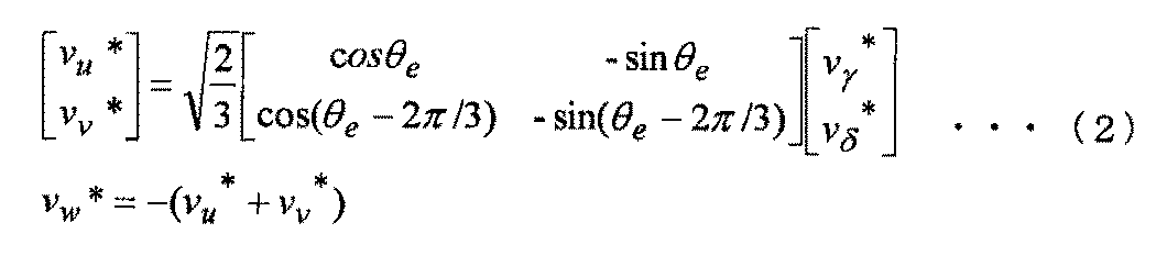
- the coordinate converter 18 performs reverse conversion of the ⁇ -axis voltage command value v ⁇ * and the ⁇ -axis voltage command value v ⁇ * based on the estimated rotor position ⁇ e given from the position / velocity estimation unit 20, thereby obtaining a motor voltage.
- V a of the U-phase component the U-phase voltage command value representing a V-phase component and a W-phase component v u *, V-phase voltage value v v * and the W-phase voltage command value v w * voltage command value of three-phase consisting of Are output to the inverter circuit unit 2.
- equation (2) is used for this inverse transformation.
- the inverter circuit unit 2 generates a pulse-width-modulated signal based on three-phase voltage command values (v u * , v v *, and v w * ) representing the voltage to be applied to the motor 1, and voltage command value of the phase (v u *, v v * and v w *) of the motor current I a corresponding to the supplied to the armature winding of the motor 1 drives the motor 1.
- the step-out detection unit 21 estimates the rotation speed of the rotor using an estimation method (for example, refer to Patent Document 5) different from the estimation method of the rotation speed of the rotor employed in the position / speed estimation unit 20. If the difference is large, the motor 1 is forcibly stopped by assuming that the step-out has occurred.
- an estimation method for example, refer to Patent Document 5
- FIG. 4 is a block diagram showing a detailed configuration example of the speed control unit 17 of FIG.
- the speed control unit 17 includes an adder 51, a PI controller 52, and a repeat compensator 53.
- the speed control unit 17 generates a repetitive compensation signal having a repetitive compensation value ⁇ erc based on the speed deviation one cycle before corresponding to the fluctuation of the load torque, and the speed command of the motor 1 in particular.
- the variation of the load torque of the motor is compensated by adding to the speed deviation ( ⁇ * ⁇ e ) between the value and the estimated speed value.
- an adder 51 repeats compensation having a repeat compensation value ⁇ erc from the repeat compensator 53 for a speed deviation ( ⁇ * ⁇ e ) between the speed command value of the motor 1 and the estimated speed value.
- a signal is generated and output to the PI controller 52 and the repetitive compensator 53.
- the PI controller 52 uses, for example, a known PI (Proportional International) control method to control the ⁇ -axis current command value i ⁇ *. Is generated and output.
- the repeat compensator 53 generates a repeat compensation signal having a repeat compensation value ⁇ erc using the following equation (3), and outputs it to the adder 51.
- L is the period of torque pulsation
- s is the Laplace operator
- e is the base of the natural logarithm.
- the repetitive compensation control is an effective control system for following periodic target signals appearing in the repetitive motion of the robot and for removing periodic disturbances synchronized with the rotational speed generated in the rotating system such as a motor.
- the basic idea is the “internal model principle” required for servo systems, which is a servo system with a generator of a periodic signal in the feedback. Its feature is that it uses the deviation signal of one cycle before, and is a kind of learning control system in which the speed deviation decreases by continuing the repeated operation.
- the speed control unit 17 determines the repetitive compensation value ⁇ erc based on the load torque deviation signal one cycle before having a speed deviation ⁇ er corresponding to the load torque deviation. And generating the repetitive compensation signal, and adding the repetitive compensation signal to the speed deviation ( ⁇ * ⁇ e ) between the speed command value and the speed estimated value of the motor 1. Can compensate for fluctuations.
- the rotation speed of the motor can be kept dynamically constant. For example, in an impact electric tool, more effective striking and stable tightening torque can be generated. It becomes possible. In addition, it is possible to prevent damage to the striking mechanism, such as motor step-out and spindle 4 retreating excessively to collide with the barrier and break.
- FIG. 5 is a block diagram showing a detailed configuration example of a speed control unit 17A according to a modified example provided in place of the speed control unit 17 of FIG.
- the speed control unit 17 ⁇ / b> A includes a PI controller 52, a resonance filter 54, and an adder 55.
- the PI controller 52 uses a known PI (Proportional Interval) control method based on the speed deviation ( ⁇ * ⁇ e ), for example, to obtain a normal ⁇ -axis current command value i ⁇ * (S5). And output to the adder 55.
- the resonance filter 54 Based on the speed deviation ( ⁇ * ⁇ e ), the resonance filter 54 generates a cancel value i qc (S6) that compensates for periodic pulsation of the load torque using, for example, the following equation (4).
- the adder 55 adds the cancel value i qc to the normal ⁇ -axis current command value i ⁇ * and outputs it to the subsequent stage as the operation amount of the speed control unit 17A.
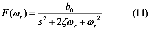
- F ( ⁇ r ) is a transfer function of the resonance filter 54 and is expressed by the following equation (11).
- ⁇ r is an angular velocity (frequency) of torque pulsation
- b 0 and ⁇ are predetermined constants, respectively
- s is a Laplace operator
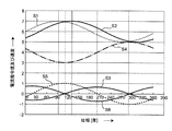
- FIG. 6 is a graph for explaining the principle of reducing the speed fluctuation in the speed controller 17A of FIG. 5, and FIG. 7 is a graph showing the frequency characteristics of the amplitude and phase of the resonance filter 54 of FIG.
- the current command value shift S3 occurs between the ideal current command value S1 and the actual current command value S2 due to control delay or the like.
- the speed fluctuation S4 occurs due to the current command value deviation S3.
- the phase of the cancel signal S6 is advanced by 90 degrees with respect to the speed deviation S5 from the target.
- the resonance filter 54 having the transfer function F ( ⁇ r ) of the above equation (11) is used.
- the frequency characteristic of the transfer function F ( ⁇ r ) is as shown in FIG. 7, and has one resonance point, only the frequency component at that resonance point is extracted, and only the phase of the frequency component is advanced by 90 degrees. Waveforms can be generated.
- the speed deviation ( ⁇ * ⁇ e ) is input to the resonance filter 54, and the cancel value i qc is output from the resonance filter 54. Since the cancel value i qc acts in a direction to eliminate the speed deviation, the rotation speed of the motor 1 is stabilized.
- the speed control unit 17A extracts a component of a predetermined resonance frequency from the speed deviation between the speed command value and the speed estimated value of the motor 1, and By adding the resonance frequency component to the manipulated variable of the speed control unit 17A as a cancel value for compensating for periodic fluctuations in the load torque, fluctuations in the load torque of the motor can be compensated.
- the rotation speed of the motor can be kept dynamically constant. For example, in an impact electric tool, more effective striking and stable tightening torque can be generated. It becomes possible. In addition, it is possible to prevent damage to the striking mechanism, such as motor step-out and spindle 4 retreating excessively to collide with the barrier and break.
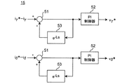
- FIG. 8 is a block diagram showing a detailed configuration example of the current control unit 15 in another embodiment.
- the current control unit 15 includes an adder 51, a PI controller 52, and a repeat compensator 53.
- the current control unit 15 repeatedly generates a compensation value based on the current deviation of the load torque of one cycle before, and uses the repetition compensation value between the current command value of the motor and the current estimated value. It is characterized by comprising a repetitive compensation unit that compensates for fluctuations in the load torque of the motor by adding to the current deviation.
- the current control unit 15 of the present embodiment generates a repetitive compensation signal having a repetitive compensation value based on a current deviation signal one cycle before having a current deviation corresponding to a change in load torque, and the repetitive compensation By adding the signal to the current deviation between the current command value of the motor 1 and the estimated current value, fluctuations in the load torque of the motor 1 can be compensated.
- the rotation speed of the motor can be kept dynamically constant. For example, in an impact electric tool, more effective striking and stable tightening torque can be generated. It becomes possible. In addition, it is possible to prevent damage to the striking mechanism, such as motor step-out and spindle 4 retreating excessively to collide with the barrier and break.
- FIG. 9 is a block diagram showing a detailed configuration example of a current control unit 15A according to a modification of the current control unit 15 in another embodiment.
- the current control unit 15 ⁇ / b> A includes a PI controller 52, a resonance filter 54, and an adder 55.
- the current control unit 15A extracts a predetermined resonance frequency component from the current deviation between the motor current command value and the current estimation value, and uses the resonance frequency component as a cycle of the load torque.
- a resonance type filter is provided that compensates for fluctuations in the load torque of the motor by adding it to the operation amount of the current control unit as a cancel value that compensates for local fluctuations.
- the current control unit 15A of the present embodiment extracts a predetermined resonance frequency component from the speed deviation between the motor speed command value and the estimated speed value, and uses the resonance frequency component as a periodic component of the load torque. By adding to the operation amount of the current control unit 15A as a cancel value that compensates for a large variation, it is possible to compensate for a variation in the load torque of the motor.
- the rotation speed of the motor can be kept dynamically constant. For example, in an impact electric tool, more effective striking and stable tightening torque can be generated. It becomes possible. In addition, it is possible to prevent damage to the striking mechanism, such as motor step-out and spindle 4 retreating excessively to collide with the barrier and break.
Landscapes
- Engineering & Computer Science (AREA)
- Mechanical Engineering (AREA)
- Control Of Electric Motors In General (AREA)
Abstract
Description
モータと、前記モータに連結された打撃機構と、前記モータの動作を制御する制御部を備えたインパクト電動工具において、
前記制御部は、前記打撃機構に起因する周期的な前記モータの負荷トルクの変動を補償することで、前記モータの回転数を一定に保持する速度制御部もしくは電流制御部を備えたことを特徴とする。

2 インバータ回路部
3 モータ制御部
4 スピンドル
5 ハンマ
6 アンビル
7 ユーザーインターフェース部(UI部)
11 電流検出器
12 座標変換器
13,14 減算器
15 電流制御部
16 磁束制御部
17,17A 速度制御部
18 座標変換器
19 減算器
20 位置・速度推定部
21 脱調検出部
22 トルク脈動周期推定部
51 加算器
52 PI制御器
53 繰り返し補償器
54 共振型フィルタ
55 加算器
Claims (6)
- モータと、前記モータに連結された打撃機構と、前記モータの動作を制御する制御部を備えたインパクト電動工具において、
前記制御部は、前記打撃機構に起因する周期的な前記モータの負荷トルクの変動を補償することで、前記モータの回転数を一定に保持する速度制御部もしくは電流制御部を備えたことを特徴とするインパクト電動工具。 - 前記速度制御部は、1周期前の負荷トルクの速度偏差に基づいて繰り返し補償値を発生して、当該繰り返し補償値を前記モータの速度指令値と速度推定値との間の速度偏差に加算することで、前記モータの負荷トルクの変動を補償する繰り返し補償部を備えたことを特徴とする請求項1記載のインパクト電動工具。
- 前記速度制御部は、前記モータの速度指令値と速度推定値との間の速度偏差から所定の共振周波数の成分を抽出して、当該共振周波数の成分を、前記負荷トルクの周期的な変動を補償するキャンセル値として前記速度制御部の操作量に加算することで、前記モータの負荷トルクの変動を補償する共振型フィルタを備えたことを特徴とする請求項1記載のインパクト電動工具。
- 前記電流制御部は、1周期前の負荷トルクの電流偏差に基づいて繰り返し補償値を発生して、当該繰り返し補償値を前記モータの電流指令値と電流推定値との間の電流偏差に加算することで、前記モータの負荷トルクの変動を補償する繰り返し補償部を備えたことを特徴とする請求項1記載のインパクト電動工具。
- 前記電流制御部は、前記モータの電流指令値と電流推定値との間の電流偏差から所定の共振周波数の成分を抽出して、当該共振周波数の成分を、前記負荷トルクの周期的な変動を補償するキャンセル値として前記電流制御部の操作量に加算することで、前記モータの負荷トルクの変動を補償する共振型フィルタを備えたことを特徴とする請求項1記載のインパクト電動工具。
- 前記打撃機構に起因する周期的な前記モータの負荷トルク変動の周波数もしくは周期を、前記モータのトルク発生に寄与する電流の脈動成分の周波数もしくは周期から得ることを特徴とする請求項1記載のインパクト電動工具。
Priority Applications (4)
| Application Number | Priority Date | Filing Date | Title |
|---|---|---|---|
| JP2019525155A JPWO2018230141A1 (ja) | 2017-06-16 | 2018-04-17 | インパクト電動工具 |
| US16/619,554 US20200130153A1 (en) | 2017-06-16 | 2018-04-17 | Impact electrical tool |
| EP18816965.0A EP3639976A4 (en) | 2017-06-16 | 2018-04-17 | ROTARY PERCUSSION TOOL |
| CN201880039647.1A CN110809504A (zh) | 2017-06-16 | 2018-04-17 | 冲击式电动工具 |
Applications Claiming Priority (2)
| Application Number | Priority Date | Filing Date | Title |
|---|---|---|---|
| JP2017118969 | 2017-06-16 | ||
| JP2017-118969 | 2017-06-16 |
Publications (1)
| Publication Number | Publication Date |
|---|---|
| WO2018230141A1 true WO2018230141A1 (ja) | 2018-12-20 |
Family
ID=64658626
Family Applications (1)
| Application Number | Title | Priority Date | Filing Date |
|---|---|---|---|
| PCT/JP2018/015812 Ceased WO2018230141A1 (ja) | 2017-06-16 | 2018-04-17 | インパクト電動工具 |
Country Status (5)
| Country | Link |
|---|---|
| US (1) | US20200130153A1 (ja) |
| EP (1) | EP3639976A4 (ja) |
| JP (1) | JPWO2018230141A1 (ja) |
| CN (1) | CN110809504A (ja) |
| WO (1) | WO2018230141A1 (ja) |
Cited By (15)
| Publication number | Priority date | Publication date | Assignee | Title |
|---|---|---|---|---|
| WO2020217627A1 (ja) * | 2019-04-24 | 2020-10-29 | パナソニックIpマネジメント株式会社 | 電動工具 |
| WO2020261764A1 (ja) * | 2019-06-28 | 2020-12-30 | パナソニックIpマネジメント株式会社 | インパクト工具 |
| WO2021002120A1 (ja) * | 2019-07-02 | 2021-01-07 | パナソニックIpマネジメント株式会社 | インパクト工具 |
| JP2021007998A (ja) * | 2019-06-28 | 2021-01-28 | パナソニックIpマネジメント株式会社 | インパクト工具 |
| JP2021007997A (ja) * | 2019-06-28 | 2021-01-28 | パナソニックIpマネジメント株式会社 | インパクト工具 |
| JP2021010981A (ja) * | 2019-07-05 | 2021-02-04 | パナソニックIpマネジメント株式会社 | インパクト工具 |
| JP2021010982A (ja) * | 2019-07-05 | 2021-02-04 | パナソニックIpマネジメント株式会社 | インパクト工具 |
| WO2021095533A1 (ja) * | 2019-11-15 | 2021-05-20 | パナソニックIpマネジメント株式会社 | 電動工具、制御方法、カムアウト検知方法、及びプログラム |
| WO2021095470A1 (ja) * | 2019-11-15 | 2021-05-20 | パナソニックIpマネジメント株式会社 | 電動工具、制御方法、及びプログラム |
| JP2021079472A (ja) * | 2019-11-15 | 2021-05-27 | パナソニックIpマネジメント株式会社 | 電動工具、制御方法、及びプログラム |
| JP2021079521A (ja) * | 2019-11-22 | 2021-05-27 | パナソニックIpマネジメント株式会社 | インパクト工具、インパクト工具の制御方法及びプログラム |
| JP2021079473A (ja) * | 2019-11-15 | 2021-05-27 | パナソニックIpマネジメント株式会社 | 電動工具、制御方法、及びプログラム |
| JP2021079509A (ja) * | 2019-11-21 | 2021-05-27 | パナソニックIpマネジメント株式会社 | 電動工具、制御方法、及びプログラム |
| JP2021079471A (ja) * | 2019-11-15 | 2021-05-27 | パナソニックIpマネジメント株式会社 | 電動工具、カムアウト検知方法及びプログラム |
| US11958173B2 (en) | 2019-11-15 | 2024-04-16 | Panasonic Intellectual Property Management Co., Ltd. | Impact tool, method for controlling the impact tool, and program |
Families Citing this family (4)
| Publication number | Priority date | Publication date | Assignee | Title |
|---|---|---|---|---|
| JP6868837B2 (ja) * | 2017-08-29 | 2021-05-12 | パナソニックIpマネジメント株式会社 | 信号処理装置及び工具 |
| JP7465190B2 (ja) * | 2020-10-12 | 2024-04-10 | パナソニックホールディングス株式会社 | 電動工具、モータ制御方法及びプログラム |
| US12479060B2 (en) | 2022-05-09 | 2025-11-25 | Milwaukee Electric Tool Corporation | Orbital polishing tool |
| CN115629627B (zh) * | 2022-09-21 | 2025-05-13 | 上海新时达机器人有限公司 | 负载端转矩波动抑制方法、电子设备及存储介质 |
Citations (12)
| Publication number | Priority date | Publication date | Assignee | Title |
|---|---|---|---|---|
| JPS5115904B2 (ja) | 1972-07-18 | 1976-05-20 | ||
| JP2000326246A (ja) * | 1999-05-13 | 2000-11-28 | Nitto Kohki Co Ltd | 電動インパクト工具 |
| JP2002199767A (ja) * | 2000-12-27 | 2002-07-12 | Aisin Seiki Co Ltd | 外乱補償制御装置 |
| JP3791229B2 (ja) | 1999-02-23 | 2006-06-28 | 松下電工株式会社 | インパクト回転工具 |
| JP2006191737A (ja) * | 2005-01-06 | 2006-07-20 | Sanyo Electric Co Ltd | モータ制御装置及びこれを有するモータ駆動システム |
| JP2007007784A (ja) * | 2005-06-30 | 2007-01-18 | Matsushita Electric Works Ltd | インパクト回転工具 |
| JP2007233732A (ja) * | 2006-03-01 | 2007-09-13 | Ricoh Co Ltd | サーボ制御装置 |
| JP4198162B2 (ja) | 2006-04-07 | 2008-12-17 | 三洋電機株式会社 | モータ制御装置 |
| JP4484447B2 (ja) | 2003-04-24 | 2010-06-16 | 株式会社エスティック | インパクト式のネジ締め装置の制御方法および装置 |
| JP4480696B2 (ja) | 2005-08-26 | 2010-06-16 | 三洋電機株式会社 | モータ制御装置 |
| JP2014121765A (ja) * | 2012-12-22 | 2014-07-03 | Hitachi Koki Co Ltd | インパクト工具 |
| JP2014140931A (ja) * | 2013-01-24 | 2014-08-07 | Hitachi Koki Co Ltd | 電動工具 |
Family Cites Families (10)
| Publication number | Priority date | Publication date | Assignee | Title |
|---|---|---|---|---|
| JPS50143170A (ja) * | 1974-05-07 | 1975-11-18 | ||
| JP3456949B2 (ja) * | 2000-06-19 | 2003-10-14 | 株式会社エスティック | ネジ締め装置の制御方法および装置 |
| JP4476314B2 (ja) * | 2007-08-10 | 2010-06-09 | 三洋電機株式会社 | モータ制御装置及び圧縮機 |
| JP5845433B2 (ja) * | 2010-03-08 | 2016-01-20 | パナソニックIpマネジメント株式会社 | モータ駆動装置 |
| CN104936746B (zh) * | 2013-01-24 | 2017-06-09 | 日立工机株式会社 | 电动工具 |
| CN105359406B (zh) * | 2013-07-09 | 2017-03-29 | 松下知识产权经营株式会社 | 电动机的控制装置 |
| JP6380924B2 (ja) * | 2014-01-06 | 2018-08-29 | パナソニックIpマネジメント株式会社 | インパクト回転工具の慣性モーメントの測定方法とその測定方法を用いたインパクト回転工具 |
| JP6297854B2 (ja) * | 2014-02-18 | 2018-03-20 | 株式会社マキタ | 回転打撃工具 |
| JP2016189668A (ja) * | 2015-03-30 | 2016-11-04 | Juki株式会社 | モータ制御装置、モータ制御方法、ミシン及びそのプログラム |
| CN205148183U (zh) * | 2015-12-07 | 2016-04-13 | 苏州市纽莱克电子科技有限公司 | 冲击扭矩电动工具 |
-
2018
- 2018-04-17 CN CN201880039647.1A patent/CN110809504A/zh active Pending
- 2018-04-17 EP EP18816965.0A patent/EP3639976A4/en not_active Withdrawn
- 2018-04-17 JP JP2019525155A patent/JPWO2018230141A1/ja active Pending
- 2018-04-17 WO PCT/JP2018/015812 patent/WO2018230141A1/ja not_active Ceased
- 2018-04-17 US US16/619,554 patent/US20200130153A1/en not_active Abandoned
Patent Citations (12)
| Publication number | Priority date | Publication date | Assignee | Title |
|---|---|---|---|---|
| JPS5115904B2 (ja) | 1972-07-18 | 1976-05-20 | ||
| JP3791229B2 (ja) | 1999-02-23 | 2006-06-28 | 松下電工株式会社 | インパクト回転工具 |
| JP2000326246A (ja) * | 1999-05-13 | 2000-11-28 | Nitto Kohki Co Ltd | 電動インパクト工具 |
| JP2002199767A (ja) * | 2000-12-27 | 2002-07-12 | Aisin Seiki Co Ltd | 外乱補償制御装置 |
| JP4484447B2 (ja) | 2003-04-24 | 2010-06-16 | 株式会社エスティック | インパクト式のネジ締め装置の制御方法および装置 |
| JP2006191737A (ja) * | 2005-01-06 | 2006-07-20 | Sanyo Electric Co Ltd | モータ制御装置及びこれを有するモータ駆動システム |
| JP2007007784A (ja) * | 2005-06-30 | 2007-01-18 | Matsushita Electric Works Ltd | インパクト回転工具 |
| JP4480696B2 (ja) | 2005-08-26 | 2010-06-16 | 三洋電機株式会社 | モータ制御装置 |
| JP2007233732A (ja) * | 2006-03-01 | 2007-09-13 | Ricoh Co Ltd | サーボ制御装置 |
| JP4198162B2 (ja) | 2006-04-07 | 2008-12-17 | 三洋電機株式会社 | モータ制御装置 |
| JP2014121765A (ja) * | 2012-12-22 | 2014-07-03 | Hitachi Koki Co Ltd | インパクト工具 |
| JP2014140931A (ja) * | 2013-01-24 | 2014-08-07 | Hitachi Koki Co Ltd | 電動工具 |
Non-Patent Citations (1)
| Title |
|---|
| See also references of EP3639976A4 * |
Cited By (32)
| Publication number | Priority date | Publication date | Assignee | Title |
|---|---|---|---|---|
| JP7515095B2 (ja) | 2019-04-24 | 2024-07-12 | パナソニックIpマネジメント株式会社 | 電動工具 |
| JP7496569B2 (ja) | 2019-04-24 | 2024-06-07 | パナソニックIpマネジメント株式会社 | 電動工具 |
| JP2023073480A (ja) * | 2019-04-24 | 2023-05-25 | パナソニックIpマネジメント株式会社 | 電動工具 |
| EP3960373A4 (en) * | 2019-04-24 | 2022-06-01 | Panasonic Intellectual Property Management Co., Ltd. | POWER TOOL |
| WO2020217627A1 (ja) * | 2019-04-24 | 2020-10-29 | パナソニックIpマネジメント株式会社 | 電動工具 |
| US12083652B2 (en) | 2019-04-24 | 2024-09-10 | Panasonic Intellectual Property Management Co., Ltd. | Electric power tool |
| JP2020179449A (ja) * | 2019-04-24 | 2020-11-05 | パナソニックIpマネジメント株式会社 | 電動工具 |
| JP2021007997A (ja) * | 2019-06-28 | 2021-01-28 | パナソニックIpマネジメント株式会社 | インパクト工具 |
| JP7706105B2 (ja) | 2019-06-28 | 2025-07-11 | パナソニックIpマネジメント株式会社 | インパクト工具 |
| US12053863B2 (en) | 2019-06-28 | 2024-08-06 | Panasonic Intellectual Property Management Co., Ltd. | Impact tool |
| JP2021007998A (ja) * | 2019-06-28 | 2021-01-28 | パナソニックIpマネジメント株式会社 | インパクト工具 |
| JP7369994B2 (ja) | 2019-06-28 | 2023-10-27 | パナソニックIpマネジメント株式会社 | インパクト工具 |
| WO2020261764A1 (ja) * | 2019-06-28 | 2020-12-30 | パナソニックIpマネジメント株式会社 | インパクト工具 |
| WO2021002120A1 (ja) * | 2019-07-02 | 2021-01-07 | パナソニックIpマネジメント株式会社 | インパクト工具 |
| JP2021010982A (ja) * | 2019-07-05 | 2021-02-04 | パナソニックIpマネジメント株式会社 | インパクト工具 |
| JP2021010981A (ja) * | 2019-07-05 | 2021-02-04 | パナソニックIpマネジメント株式会社 | インパクト工具 |
| JP7352794B2 (ja) | 2019-07-05 | 2023-09-29 | パナソニックIpマネジメント株式会社 | インパクト工具 |
| JP7352793B2 (ja) | 2019-07-05 | 2023-09-29 | パナソニックIpマネジメント株式会社 | インパクト工具 |
| WO2021095533A1 (ja) * | 2019-11-15 | 2021-05-20 | パナソニックIpマネジメント株式会社 | 電動工具、制御方法、カムアウト検知方法、及びプログラム |
| JP2021079472A (ja) * | 2019-11-15 | 2021-05-27 | パナソニックIpマネジメント株式会社 | 電動工具、制御方法、及びプログラム |
| JP7296587B2 (ja) | 2019-11-15 | 2023-06-23 | パナソニックIpマネジメント株式会社 | 電動工具、制御方法、及びプログラム |
| WO2021095470A1 (ja) * | 2019-11-15 | 2021-05-20 | パナソニックIpマネジメント株式会社 | 電動工具、制御方法、及びプログラム |
| JP2021079471A (ja) * | 2019-11-15 | 2021-05-27 | パナソニックIpマネジメント株式会社 | 電動工具、カムアウト検知方法及びプログラム |
| JP7390587B2 (ja) | 2019-11-15 | 2023-12-04 | パナソニックIpマネジメント株式会社 | 電動工具、カムアウト検知方法及びプログラム |
| US11958173B2 (en) | 2019-11-15 | 2024-04-16 | Panasonic Intellectual Property Management Co., Ltd. | Impact tool, method for controlling the impact tool, and program |
| JP7296586B2 (ja) | 2019-11-15 | 2023-06-23 | パナソニックIpマネジメント株式会社 | 電動工具、制御方法、及びプログラム |
| JP2021079473A (ja) * | 2019-11-15 | 2021-05-27 | パナソニックIpマネジメント株式会社 | 電動工具、制御方法、及びプログラム |
| JP2021079509A (ja) * | 2019-11-21 | 2021-05-27 | パナソニックIpマネジメント株式会社 | 電動工具、制御方法、及びプログラム |
| JP7555045B2 (ja) | 2019-11-21 | 2024-09-24 | パナソニックIpマネジメント株式会社 | 電動工具、制御方法、及びプログラム |
| JP2021079521A (ja) * | 2019-11-22 | 2021-05-27 | パナソニックIpマネジメント株式会社 | インパクト工具、インパクト工具の制御方法及びプログラム |
| US12220790B2 (en) | 2019-11-22 | 2025-02-11 | Panasonic Intellectual Property Management Co., Ltd. | Impact tool, method for controlling the impact tool, and program |
| JP7281744B2 (ja) | 2019-11-22 | 2023-05-26 | パナソニックIpマネジメント株式会社 | インパクト工具、インパクト工具の制御方法及びプログラム |
Also Published As
| Publication number | Publication date |
|---|---|
| JPWO2018230141A1 (ja) | 2020-04-02 |
| CN110809504A (zh) | 2020-02-18 |
| EP3639976A1 (en) | 2020-04-22 |
| US20200130153A1 (en) | 2020-04-30 |
| EP3639976A4 (en) | 2020-07-15 |
Similar Documents
| Publication | Publication Date | Title |
|---|---|---|
| WO2018230141A1 (ja) | インパクト電動工具 | |
| JPWO2001015311A1 (ja) | 同期電動機制御装置、同期電動機の制御方法 | |
| WO2008010595A1 (fr) | Dispositif de commande de dispositif électrique rotatif procédé de commande de dispositif électrique rotatif, et programme de commande de dispositif électrique rotatif | |
| JP4263582B2 (ja) | ブラシレスモータ制御装置 | |
| WO2018230140A1 (ja) | 電動工具 | |
| CN108462413B (zh) | 电动机控制装置以及电动机控制方法 | |
| JPWO2015019495A1 (ja) | モータ駆動システムおよびモータ制御装置 | |
| KR20070094488A (ko) | 스테핑 모터의 제어장치 | |
| JP2009303435A (ja) | モータ制御装置 | |
| JP4764124B2 (ja) | 永久磁石型同期モータの制御装置及びその方法 | |
| JP4425091B2 (ja) | モータの位置センサレス制御回路 | |
| JP7555045B2 (ja) | 電動工具、制御方法、及びプログラム | |
| WO2020017202A1 (ja) | 電動工具、制御方法、プログラム | |
| JP5788057B1 (ja) | 同期機制御装置 | |
| JP3920750B2 (ja) | Dcブラシレスモータの制御装置 | |
| JP2005229717A (ja) | 同期電動機の電流センサレス制御方法および装置 | |
| JP2006180605A (ja) | 電動機の制御装置 | |
| JP5726273B2 (ja) | 永久磁石状態推定機能を備えた同期機制御装置およびその方法 | |
| JP7108834B2 (ja) | 動力発生装置 | |
| JP4402600B2 (ja) | 同期電動機の駆動システム及び同期電動機の駆動方法 | |
| JP4522273B2 (ja) | モータ制御装置及びこれを有するモータ駆動システム | |
| JP5186352B2 (ja) | 電動機の磁極位置推定装置 | |
| JP2010148324A (ja) | モータ制御装置 | |
| JP2009124872A (ja) | 同期電動機のV/f制御装置 | |
| JP3797484B2 (ja) | ステッピングモータの駆動装置 |
Legal Events
| Date | Code | Title | Description |
|---|---|---|---|
| 121 | Ep: the epo has been informed by wipo that ep was designated in this application |
Ref document number: 18816965 Country of ref document: EP Kind code of ref document: A1 |
|
| ENP | Entry into the national phase |
Ref document number: 2019525155 Country of ref document: JP Kind code of ref document: A |
|
| NENP | Non-entry into the national phase |
Ref country code: DE |
|
| WWE | Wipo information: entry into national phase |
Ref document number: 2018816965 Country of ref document: EP |
|
| ENP | Entry into the national phase |
Ref document number: 2018816965 Country of ref document: EP Effective date: 20200116 |