WO2018230175A1 - 駐車支援装置 - Google Patents
駐車支援装置 Download PDFInfo
- Publication number
- WO2018230175A1 WO2018230175A1 PCT/JP2018/016923 JP2018016923W WO2018230175A1 WO 2018230175 A1 WO2018230175 A1 WO 2018230175A1 JP 2018016923 W JP2018016923 W JP 2018016923W WO 2018230175 A1 WO2018230175 A1 WO 2018230175A1
- Authority
- WO
- WIPO (PCT)
- Prior art keywords
- parking
- vehicle speed
- vehicle
- time
- assistance device
- Prior art date
- Legal status (The legal status is an assumption and is not a legal conclusion. Google has not performed a legal analysis and makes no representation as to the accuracy of the status listed.)
- Ceased
Links
Images


Classifications
-
- B—PERFORMING OPERATIONS; TRANSPORTING
- B60—VEHICLES IN GENERAL
- B60W—CONJOINT CONTROL OF VEHICLE SUB-UNITS OF DIFFERENT TYPE OR DIFFERENT FUNCTION; CONTROL SYSTEMS SPECIALLY ADAPTED FOR HYBRID VEHICLES; ROAD VEHICLE DRIVE CONTROL SYSTEMS FOR PURPOSES NOT RELATED TO THE CONTROL OF A PARTICULAR SUB-UNIT
- B60W30/00—Purposes of road vehicle drive control systems not related to the control of a particular sub-unit, e.g. of systems using conjoint control of vehicle sub-units
- B60W30/06—Automatic manoeuvring for parking
-
- B—PERFORMING OPERATIONS; TRANSPORTING
- B60—VEHICLES IN GENERAL
- B60W—CONJOINT CONTROL OF VEHICLE SUB-UNITS OF DIFFERENT TYPE OR DIFFERENT FUNCTION; CONTROL SYSTEMS SPECIALLY ADAPTED FOR HYBRID VEHICLES; ROAD VEHICLE DRIVE CONTROL SYSTEMS FOR PURPOSES NOT RELATED TO THE CONTROL OF A PARTICULAR SUB-UNIT
- B60W40/00—Estimation or calculation of non-directly measurable driving parameters for road vehicle drive control systems not related to the control of a particular sub unit, e.g. by using mathematical models
- B60W40/08—Estimation or calculation of non-directly measurable driving parameters for road vehicle drive control systems not related to the control of a particular sub unit, e.g. by using mathematical models related to drivers or passengers
- B60W40/09—Driving style or behaviour
-
- B—PERFORMING OPERATIONS; TRANSPORTING
- B60—VEHICLES IN GENERAL
- B60W—CONJOINT CONTROL OF VEHICLE SUB-UNITS OF DIFFERENT TYPE OR DIFFERENT FUNCTION; CONTROL SYSTEMS SPECIALLY ADAPTED FOR HYBRID VEHICLES; ROAD VEHICLE DRIVE CONTROL SYSTEMS FOR PURPOSES NOT RELATED TO THE CONTROL OF A PARTICULAR SUB-UNIT
- B60W40/00—Estimation or calculation of non-directly measurable driving parameters for road vehicle drive control systems not related to the control of a particular sub unit, e.g. by using mathematical models
- B60W40/10—Estimation or calculation of non-directly measurable driving parameters for road vehicle drive control systems not related to the control of a particular sub unit, e.g. by using mathematical models related to vehicle motion
- B60W40/105—Speed
-
- B—PERFORMING OPERATIONS; TRANSPORTING
- B62—LAND VEHICLES FOR TRAVELLING OTHERWISE THAN ON RAILS
- B62D—MOTOR VEHICLES; TRAILERS
- B62D15/00—Steering not otherwise provided for
- B62D15/02—Steering position indicators ; Steering position determination; Steering aids
- B62D15/027—Parking aids, e.g. instruction means
- B62D15/0285—Parking performed automatically
-
- B—PERFORMING OPERATIONS; TRANSPORTING
- B60—VEHICLES IN GENERAL
- B60W—CONJOINT CONTROL OF VEHICLE SUB-UNITS OF DIFFERENT TYPE OR DIFFERENT FUNCTION; CONTROL SYSTEMS SPECIALLY ADAPTED FOR HYBRID VEHICLES; ROAD VEHICLE DRIVE CONTROL SYSTEMS FOR PURPOSES NOT RELATED TO THE CONTROL OF A PARTICULAR SUB-UNIT
- B60W50/00—Details of control systems for road vehicle drive control not related to the control of a particular sub-unit, e.g. process diagnostic or vehicle driver interfaces
- B60W2050/0062—Adapting control system settings
- B60W2050/0075—Automatic parameter input, automatic initialising or calibrating means
-
- B—PERFORMING OPERATIONS; TRANSPORTING
- B60—VEHICLES IN GENERAL
- B60W—CONJOINT CONTROL OF VEHICLE SUB-UNITS OF DIFFERENT TYPE OR DIFFERENT FUNCTION; CONTROL SYSTEMS SPECIALLY ADAPTED FOR HYBRID VEHICLES; ROAD VEHICLE DRIVE CONTROL SYSTEMS FOR PURPOSES NOT RELATED TO THE CONTROL OF A PARTICULAR SUB-UNIT
- B60W2510/00—Input parameters relating to a particular sub-units
- B60W2510/18—Braking system
-
- B—PERFORMING OPERATIONS; TRANSPORTING
- B60—VEHICLES IN GENERAL
- B60W—CONJOINT CONTROL OF VEHICLE SUB-UNITS OF DIFFERENT TYPE OR DIFFERENT FUNCTION; CONTROL SYSTEMS SPECIALLY ADAPTED FOR HYBRID VEHICLES; ROAD VEHICLE DRIVE CONTROL SYSTEMS FOR PURPOSES NOT RELATED TO THE CONTROL OF A PARTICULAR SUB-UNIT
- B60W2556/00—Input parameters relating to data
- B60W2556/10—Historical data
-
- B—PERFORMING OPERATIONS; TRANSPORTING
- B60—VEHICLES IN GENERAL
- B60W—CONJOINT CONTROL OF VEHICLE SUB-UNITS OF DIFFERENT TYPE OR DIFFERENT FUNCTION; CONTROL SYSTEMS SPECIALLY ADAPTED FOR HYBRID VEHICLES; ROAD VEHICLE DRIVE CONTROL SYSTEMS FOR PURPOSES NOT RELATED TO THE CONTROL OF A PARTICULAR SUB-UNIT
- B60W2720/00—Output or target parameters relating to overall vehicle dynamics
- B60W2720/10—Longitudinal speed
Definitions
- the present invention relates to a parking assistance device, and more particularly to a parking assistance device that controls the speed of a vehicle when the vehicle is parked in a parking space.
- the driver's sense of security with respect to the vehicle speed varies from person to person depending on the environment around the vehicle (the presence or absence of obstacles), the driving experience of the driver, and the like.
- a conventional technique of this type for example, as described in Patent Document 1, there is known a method of decelerating a target vehicle speed of a vehicle during automatic parking according to a distance between an obstacle and the vehicle when a driver performs a brake input operation. It has been.
- Patent Document 1 if the target vehicle speed is parked at the upper limit vehicle speed corrected to the deceleration side, the driver may feel annoyed conversely.
- the present invention has been made in view of the above-described problems, and the object of the present invention is to, for example, become familiar with automatic parking control after starting to use automatic parking control and correcting the target vehicle speed of the vehicle to the deceleration side. Accordingly, it is an object of the present invention to provide a parking assistance device that can reduce the annoyance felt by the driver.
- a parking assistance device is a parking assistance device that supports the parking of the vehicle by controlling the vehicle speed at the time of parking.
- the vehicle speed of the vehicle at the time of parking is increased according to the behavior from the time.
- the present invention for example, after starting to use automatic parking control and the target vehicle speed of the vehicle is corrected to the deceleration side, it is possible to reduce the annoyance felt by the driver due to the familiarity of automatic parking control.
- FIG. 1 It is a figure showing a schematic structure of an automatic parking system by a 1st embodiment of a parking assistance device concerning the present invention.
- FIG. 1 It is a block diagram which shows the input / output signal relationship of the parking assistance apparatus shown in FIG. 1, a driving force control apparatus, a braking force control apparatus, and a shift control apparatus.
- FIG. 1 It is a flowchart which shows roughly the control content of the whole control method by the parking assistance apparatus shown by FIG.
- FIG. 5 surface which shows roughly the parking pattern acquisition process shown by FIG. 5 is a flowchart schematically showing a target vehicle speed calculation process shown in FIG. 4.
- FIG. 5 is a flowchart schematically showing a target vehicle speed calculation process shown in FIG. 4.
- FIG. 4 It is a flowchart which shows roughly the target vehicle speed basic value calculating process shown by FIG.
- FIG. 10 is a flowchart schematically showing target vehicle speed increase determination calculation processing shown in FIG. 9.
- FIG. It is a calculation map of the target vehicle speed increase amount.
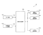
- This automatic parking system 1 mainly includes a parking assist device 100, a display HMI device 101, an external recognition input device 102 composed of a camera, sonar, radar, etc., a driving force control device 103 composed of an engine, a motor, etc., a brake, etc.
- the braking force control device 104 and the shift control device 106 for forward / reverse switching are connected to each other via a communication means 110 such as CAN.
- the information of the parking assist device 100 is output to the HMI device 101, the driving force control device 103, the braking force control device 104, and the shift control device 106, while the HMI device 101, the outside world recognition input Information on the device 102, the driving force control device 103, the braking force control device 104, and the shift control device 106 is output to the parking assistance device 100.
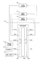
- outputs from the external recognition input device 102, the driving force control device 103, the braking force control device 104, and the shift control device 106 are input to the input unit 100 i of the parking assistance device 100,
- the signals are output to the driving force control device 103, the braking force control device 104, and the shift control device 106 via the computer 100c as an arithmetic device and the output unit 100o, respectively.
- the input unit 100i of the parking assistance device 100 includes information on the parking start SW 101a for starting parking assistance, a vehicle speed sensor, and the like in addition to the detection information of the parking area and adjacent obstacles in the external recognition input device 102.
- the vehicle speed information from the vehicle speed input device 105 is input, and the parking assistance device 100 controls the driving force in the driving force control device 103 and the braking force in the braking force control device 104 based on these information, The vehicle speed of the vehicle during parking is controlled.
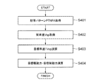
- a parking pattern PTNPA is acquired from information of the external recognition input device 102 or the like (see FIG. 5 for details) (S401), and then the actual vehicle speed Vsp is determined from the information of the vehicle speed input device 105. (S402), the target vehicle speed TVsp is calculated (S403), and then the target driving force and the target braking force are calculated (S404).
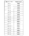
- the parking pattern PTNPA as FIG. 5 shows, the several pattern is set by the combination of the parking method and a parking area adjacent obstacle, and parking pattern PTNPA is acquired based on this.
- the target vehicle speed basic value TVspB is calculated (S601), and then the target vehicle speed upper limit value TVspLMT is calculated (S602). ), The target vehicle speed TVsp corresponding to the target vehicle speed basic value TVspB and the target vehicle speed upper limit value TVspLMT is calculated (S603).
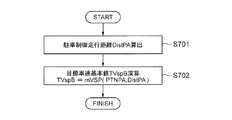
- the parking control travel distance DistPA is calculated (S701), and the target vehicle speed basic value TVspB is obtained therefrom (S702).
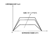
- the relationship between the target vehicle speed basic value TVspB and the parking control travel distance DistPA has a different relationship depending on the parking pattern PTNPA, for example, as shown in FIG.
- the target vehicle speed increase determination fVSPIOK [PTNPA] is calculated (S901).
- the increase amount DTVspLMT is calculated (S903), and the target is set to the amount obtained by adding the increase amount DTVspLMT to the reference target vehicle speed upper limit value TVspLMT obtained from information such as the parking pattern PTNPA and the shift control device 106.
- the vehicle speed upper limit TVspLMT is reset (S905). If the target vehicle speed increase determination is negative (S902), the reference target vehicle speed upper limit TVspLMT remains the same (S904).
- the target vehicle speed increase determination fVSPIOK [PTNPA] calculation process (S901), first, whether or not the driver stepped on the brake in the previous parking (that is, whether or not there was a brake operation by the driver during the previous parking). ) Is determined (S1001), and the brake OFF continuous parking number CTNAPBRKOF [PTNPA], which is the number of times that parking without brake operation is continuously performed, is obtained (S1002). In addition, when the brake is stepped on by the driver in the previous parking (that is, the brake operation is performed by the driver in the previous parking), the number of brake OFF continuous parking CTNAPBRKOF [PTNPA] is set to 0 (S1003) .
- the brake OFF continuous parking frequency CTNAPBRKOF [PTNPA] is obtained for each parking pattern PTNPA.
- a certain threshold TH [PTNPA] that is, when the driver has continuously parked without brake operation until the last parking
- the target vehicle speed increase determination flag is set (that is, the target vehicle speed increase determination fVSPIOK [PTNPA] is set to 1) (S1005), and then the brake OFF consecutive parking number CTNAPBRKOF [PTNPA] is reset (S1007), and the process ends.
- the target vehicle speed increase determination flag is not set (that is, the target vehicle speed increase determination fVSPIOK [PTNPA] is set to 0) (S1006), and the process is terminated.
- the threshold value TH [PTNPA] described above is changed according to the parking pattern PTNPA, as in the case of the brake OFF continuous parking count CTNAPBRKOF [PTNPA].
- the calculation process of the increase amount DTVspLMT shown in FIG. 9 (S903), that is, the calculation process of the increase amount DTVspLMT when increasing the target vehicle speed TVsp will be described with reference to FIG.
- the increase amount DTVspLMT is set according to the parking pattern PTNPA, and the increase amount DTVspLMT is appropriately determined using this map.
- an appropriate target vehicle speed upper limit value TVspLMT is calculated in the target vehicle speed basic value TVspB calculation process (S601).
- the appropriate target vehicle speed basic value TVspB and the target vehicle speed upper limit value TVspLMT are calculated in the parking assist vehicle speed control process (S302) shown in FIG. 3, and the target vehicle speed basic value TVspB and the target vehicle speed upper limit value are calculated.
- the appropriate target vehicle speed TVsp corresponding to the parking pattern PTNPA and the behavior during parking is calculated from the value TVspLMT.
- the top (A) shows parking support timing, and (B) shows the state of the brake SW at that time. If there is no brake operation during the parking support period t1-t3, the number of brake OFF consecutive parking times CTNAPBRKOF [PTNPA] is incremented as shown in (C) at the timing of the next parking support start t4. Then, at the time of parking support at t6 when the count of the brake-off continuous parking count CTNAPBRKOF [PTNPA] exceeds the threshold value TH [PTNPA], the target vehicle speed increase determination flag rises (ie, the target vehicle speed) as shown in (D).
- Increase determination fVSPIOK [PTNPA] becomes 1), and as shown in (E), the upper limit vehicle speed (the upper limit speed when moving forward, the upper limit speed when moving backward) is set to increase, and the vehicle speed of the vehicle during parking is increased.
- the vehicle speed of the vehicle at the time of parking is increased as a whole, but needless to say, the method of increasing the vehicle speed at the time of parking is not limited to this. Needless to say, the upper limit speed for forward travel and the upper limit speed for reverse travel can be set individually and appropriately.
- the upper limit vehicle speed (target vehicle speed upper limit value) is set based on the familiarity with automatic parking control.
- the second embodiment is another method of the target vehicle speed increase determination calculation shown in FIG. 10 in the first embodiment described above. Since other configurations are the same as those in the first embodiment, detailed description thereof is omitted.
- a target vehicle speed increase determination flag is set (that is, the target vehicle speed increase determination fVSPIOK [PTNPA] is set to 1) (S1302). If it is equal to or greater than the predetermined value ⁇ [PTNPA], the target vehicle speed increase determination flag is not raised (that is, the target vehicle speed increase determination fVSPIOK [PTNPA] is set to 0) (S1303).
- the elapsed time TMRAPEXE [PTNPA] from the previous parking and the predetermined value ⁇ [PTNPA] for determination are set for each parking pattern PTNPA. That is, in the second embodiment, when the elapsed time from the previous parking is short, it is considered that the driver is accustomed to the automatic parking control. In this case, the upper limit vehicle speed (target vehicle speed upper limit value) is increased. The vehicle speed of the vehicle at the time of parking is increased.
- the third embodiment is also another method of the target vehicle speed increase determination calculation shown in FIG. 10 in the first embodiment. Since other configurations are the same as those in the first embodiment, detailed description thereof is omitted.
- a target vehicle speed increase determination flag is set (ie, target vehicle speed increase determination fVSPIOK [PTNPA] is set to 1) (S1402). If the value is less than the predetermined value ⁇ [PTNPA], the target vehicle speed increase determination flag is not set (that is, the target vehicle speed increase determination fVSPIOK [PTNPA] is set to 0). (S1403).
- the travel distance DISAPEXE [PTNPA] from the previous parking and the predetermined value ⁇ [PTNPA] for determination are set for each parking pattern PTNPA. That is, in the third embodiment, the driver is considered accustomed to driving when the travel distance from the previous parking is long. In this case, the upper limit vehicle speed (target vehicle speed upper limit value) is increased, Increase the vehicle speed of the vehicle at the time.
- the fourth embodiment is another method for calculating the target vehicle speed upper limit value shown in FIG. 9 in the first embodiment described above, and mainly includes on / off determination of the brake SW. Since other configurations are the same as those in the first embodiment, detailed description thereof is omitted.
- the vehicle speed upper limit value (target vehicle speed upper limit value) is limited by the brake operation during parking.
- the upper limit value of the vehicle speed is increased (returned) when there is no brake operation.
- the brake SW is turned on / off after parking is started (S1501).
- the target vehicle speed upper limit value TVspLMT is calculated when the brake is on, and the upper limit of the vehicle speed is set by the brake operation during parking. The value is limited (S1506), and the maximum deceleration GMAX at that time is stored (S1507).
- the target vehicle speed increase determination fVSPIOK [PTNPA] is calculated (S1502). If the target vehicle speed needs to be increased as a result of the calculation (S1503), the increase amount DTVspLMT is calculated (S1504).
- the target vehicle speed upper limit TVspLMT is corrected (changed) with the correction GAIN [GMAX] corresponding to the maximum deceleration GMAX to reset the target vehicle speed upper limit TVspLMT when there is no brake operation (S1505).
- GAIN GAIN
- the correction GAIN is set to be smaller (that is, the vehicle speed increase DTVspLMT is decreased) to correct the target vehicle speed upper limit increase after sudden deceleration to be smaller.
- the amount of increase in the target vehicle speed upper limit after slow deceleration is greatly corrected.
- the vehicle when the vehicle is parked, such as the driver's brake operation, the elapsed time from the previous parking, the travel distance from the previous parking, the deceleration at the time of parking, etc.
- the vehicle speed at parking for example, after using the automatic parking control and the target vehicle speed of the vehicle is corrected to the deceleration side, It is possible to reduce the annoyance felt by the driver.
- the target vehicle speed is based on the vehicle behavior such as the driver's brake operation, the elapsed time from the previous parking, the travel distance from the previous parking, and the deceleration at the time of parking.
- vehicle behavior such as the driver's brake operation, the elapsed time from the previous parking, the travel distance from the previous parking, and the deceleration at the time of parking.
- the increase in the vehicle speed including the upper limit value is determined, it is needless to say that the increase in the vehicle speed including the target vehicle speed upper limit value may be determined by vehicle behavior other than the above.
- the present invention is not limited to the first to fourth embodiments described above, and includes various modifications.
- the first to fourth embodiments described above have been described in detail for easy understanding of the present invention, and are not necessarily limited to those having all the configurations described.
- a part of the configuration of an embodiment can be replaced with the configuration of another embodiment, and the configuration of another embodiment can be added to the configuration of an embodiment.
- each of the above-described configurations, functions, processing units, processing means, and the like may be realized by hardware by designing a part or all of them with, for example, an integrated circuit.
- Each of the above-described configurations, functions, and the like may be realized by software by interpreting and executing a program that realizes each function by the processor.
- Information such as programs, tables, and files for realizing each function can be stored in a memory, a hard disk, a storage device such as an SSD (Solid State Drive), or a recording medium such as an IC card, an SD card, or a DVD.
- control lines and information lines indicate what is considered necessary for the explanation, and not all the control lines and information lines on the product are necessarily shown. Actually, it may be considered that almost all the components are connected to each other.
Landscapes
- Engineering & Computer Science (AREA)
- Transportation (AREA)
- Mechanical Engineering (AREA)
- Automation & Control Theory (AREA)
- Physics & Mathematics (AREA)
- Mathematical Physics (AREA)
- Chemical & Material Sciences (AREA)
- Combustion & Propulsion (AREA)
- Control Of Driving Devices And Active Controlling Of Vehicle (AREA)
- Regulating Braking Force (AREA)
- Traffic Control Systems (AREA)
Abstract
例えば自動駐車制御を使い始めで車両の目標車速が減速側に補正されたあとに、自動駐車制御の慣れにより運転者が感じる煩わしさを低減することのできる駐車支援装置を提供する。 駐車時の車両の車速を制御して該車両の駐車を支援する駐車支援装置であって、前記車両の駐車時もしくは前回駐車時からの挙動に応じて駐車時における前記車両の車速を増加させる。
Description
本発明は、駐車支援装置に係り、特に、車両を駐車スペースに駐車する際に車両の速度を制御する駐車支援装置に関する。
アクセル・ブレーキ・ステアリング等を制御する自動駐車制御において、運転者の車速に対する安心感は、車両周囲の環境(障害物の有無)や運転者の運転経験等により個人ごとに異なる。この種の従来技術として、例えば特許文献1に記載のように、運転者のブレーキ入力操作したときの障害物と車両との距離に応じて自動駐車時の車両の目標車速を減速させる方法が知られている。
しかしながら、運転者が自動駐車に慣れてくると車速に対する不安感は軽減していく。そのため、上記特許文献1に記載のように、目標車速を減速側に補正された上限車速で駐車すると、運転者が逆に煩わしさを感じてしまう可能性がある。
本発明は、前記課題に鑑みてなされたものであって、その目的とするところは、例えば自動駐車制御を使い始めで車両の目標車速が減速側に補正されたあとに、自動駐車制御の慣れにより運転者が感じる煩わしさを低減することのできる駐車支援装置を提供することにある。
上述した課題を解決するために、本発明に係る駐車支援装置は、駐車時の車両の車速を制御して該車両の駐車を支援する駐車支援装置であって、前記車両の駐車時もしくは前回駐車時からの挙動に応じて駐車時における前記車両の車速を増加させることを特徴としている。
本発明によれば、例えば自動駐車制御を使い始めで車両の目標車速が減速側に補正されたあとに、自動駐車制御の慣れにより運転者が感じる煩わしさを低減することが可能となる。
上記した以外の課題、構成及び効果は、以下の実施形態の説明により明らかにされる。
以下、本発明の実施形態について、図面を参照しながら説明する。
以下の実施形態においては便宜上その必要があるときは、複数のセクションまたは実施形態に分割して説明するが、特に明示した場合を除き、それらはお互いに無関係なものではなく、一方は他方の一部または全部の変形形態、詳細、補足説明等の関係にある。
(第1実施形態)
まず、図1~図12を参照して、本発明に係る駐車支援装置の第1実施形態について説明する。
まず、図1~図12を参照して、本発明に係る駐車支援装置の第1実施形態について説明する。
まず初めに、図1を用いて、本発明に係る駐車支援装置の第1実施形態による自動駐車システムの概略構成を説明する。この自動駐車システム1は、主に、駐車支援装置100、表示用のHMI装置101、カメラ、ソナー、レーダ等からなる外界認識入力装置102、エンジン、モータ等からなる駆動力制御装置103、ブレーキ等からなる制動力制御装置104、前進・後退切換え用のシフト制御装置106から構成され、それらがCAN等からなる通信手段110を介して相互に通信可能に接続されている。それぞれの各種装置の関係性は、駐車支援装置100の情報がHMI装置101や駆動力制御装置103、制動力制御装置104、シフト制御装置106に出力され、他方で、HMI装置101、外界認識入力装置102、駆動力制御装置103、制動力制御装置104、シフト制御装置106の情報が駐車支援装置100に出力される関係となっている。
詳細には、図2に示されるように、外界認識入力装置102、駆動力制御装置103、制動力制御装置104、シフト制御装置106の出力が駐車支援装置100の入力部100iに入力され、中央演算装置としてのコンピュータ100c、出力部100oを介してそれぞれ駆動力制御装置103、制動力制御装置104、シフト制御装置106へ出力される。なお、駐車支援装置100の入力部100iには、外界認識入力装置102での駐車エリア、隣接障害物等の検知情報に加えて、駐車支援を開始するための駐車開始SW101aの情報、車速センサ等からなる車速入力装置105からの車速の情報が入力され、駐車支援装置100は、これらの情報を基に駆動力制御装置103における駆動力と制動力制御装置104における制動力を制御することで、駐車時における当該車両の車速を制御する。
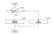
次に、図3のフローチャートを用いて、図1に示される駐車支援装置100による車両駐車時の車速制御全体の概要について説明する。
まず、駐車開始SW101aの情報から、駐車支援モードか否かを判定し(S301)、駐車支援モードの場合は駐車支援車速制御をおこない(S302)、駐車支援モードでない場合は既存の車速制御をおこなう(S303)。この制御フローは、駐車支援装置100のコンピュータ100cにプログラミングされ、予め定められた周期で繰り返し実行される。
次に、図4のフローチャートを用いて、図3に示される駐車支援車速制御処理(S302)の概略を説明する。
この駐車支援車速制御処理(S302)では、外界認識入力装置102等の情報から、駐車パターンPTNPAを取得し(詳細は図5参照)(S401)、その後、車速入力装置105の情報から実車速Vspを取得し(S402)、目標車速TVspを演算した後(S403)、目標駆動力や目標制動力を演算する(S404)。駐車パターンPTNPAについては、図5に示されるように、駐車方法、駐車エリア隣接障害物の組み合わせにより複数のパターンが設定されており、これに基づいて駐車パターンPTNPAを取得する。
図4に示される目標車速演算処理(S403)については、図6のフローチャートに示されるように、まず目標車速基本値TVspBを演算し(S601)、その後、目標車速上限値TVspLMTを演算し(S602)、目標車速基本値TVspBと目標車速上限値TVspLMTに応じた目標車速TVspを演算する(S603)。
目標車速基本値TVspBの演算処理(S601)については、図7のフローチャートに示されるように、まず駐車制御走行距離DistPAを算出し(S701)、そこから目標車速基本値TVspBを求める(S702)。目標車速基本値TVspBと駐車制御走行距離DistPAの関係は、例えば図8に示されるように、駐車パターンPTNPAに応じて異なる関係をもつ。
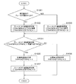
目標車速上限値TVspLMTの演算処理(S602)については、図9のフローチャートに示されるように、まず目標車速増加判定fVSPIOK[PTNPA]を演算し(S901)、その演算の結果、目標車速増加要の場合は(S902)、増加量DTVspLMTを演算し(S903)、駐車パターンPTNPAやシフト制御装置106からの情報等から求まる基準の目標車速上限値TVspLMTに増加量DTVspLMTを合わせた分となるように目標車速上限値TVspLMTを設定し直す(S905)。目標車速増加判定で否の場合は(S902)、基準の目標車速上限値TVspLMTのままとなる(S904)。
図9に示される目標車速増加判定fVSPIOK[PTNPA]の演算処理(S901)について、図10のフローチャートを用いてより具体的に説明する。
この目標車速増加判定fVSPIOK[PTNPA]の演算処理(S901)では、まず前回の駐車で運転者によってブレーキが踏まれたか否か(つまり、前回駐車時において運転者によるブレーキ操作が有ったか否か)を判定し(S1001)、ブレーキ操作の無い駐車が連続して実施された回数であるブレーキOFF連続駐車回数CTNAPBRKOF[PTNPA]を求める(S1002)。なお、前回の駐車で運転者によってブレーキが踏まれている(つまり、前回駐車時において運転者によるブレーキ操作が有る)場合は、ブレーキOFF連続駐車回数CTNAPBRKOF[PTNPA]は0にセットする(S1003)。ここでは、ブレーキOFF連続駐車回数CTNAPBRKOF[PTNPA]は、駐車パターンPTNPA毎に求める。そのブレーキOFF連続駐車回数CTNAPBRKOF[PTNPA]がある閾値TH[PTNPA]を超えた場合(つまり、前回駐車時までに運転者がブレーキ操作しない駐車を連続して所定回数実施した場合)は(S1004)、目標車速増加判定フラグを立て(すなわち、目標車速増加判定fVSPIOK[PTNPA]を1とし)(S1005)、その後、ブレーキOFF連続駐車回数CTNAPBRKOF[PTNPA]をリセットして(S1007)終了する。閾値TH[PTNPA]を超えない場合は(S1004)、目標車速増加判定フラグを立てないで(すなわち、目標車速増加判定fVSPIOK[PTNPA]を0とし)(S1006)、そのまま終了する。前述の閾値TH[PTNPA]は、ブレーキOFF連続駐車回数CTNAPBRKOF[PTNPA]と同様、駐車パターンPTNPAに応じて変更される。
次に、図11を用いて、図9に示される増加量DTVspLMTの演算処理(S903)、つまり目標車速TVspを増加する際の増加量DTVspLMTの演算処理について説明する。図11に示されるように、増加量DTVspLMTは、駐車パターンPTNPAに応じて設定されており、このマップを使って増加量DTVspLMTが適宜に決定される。これにより、目標車速基本値TVspBの演算処理(S601)において、適正な目標車速上限値TVspLMTが演算される。
上記処理を実行することで、図3に示される駐車支援車速制御処理(S302)において、適正な目標車速基本値TVspBや目標車速上限値TVspLMTが演算され、その目標車速基本値TVspBと目標車速上限値TVspLMTから駐車パターンPTNPAや駐車時の挙動に応じた適正な目標車速TVspが算出されることになる。
次に、図12のタイムチャートを用いて、図1に示される駐車支援装置100による車両駐車時の動作を説明する。最上段の(A)が駐車支援タイミングを、(B)がそのときのブレーキSWの状態を示している。駐車支援期間t1-t3の期間中にブレーキ操作がなかった場合は、次の駐車支援開始t4のタイミングで、(C)で示すようにブレーキOFF連続駐車回数CTNAPBRKOF[PTNPA]をカウントアップさせる。そして、そのブレーキOFF連続駐車回数CTNAPBRKOF[PTNPA]のカウントが閾値TH[PTNPA]を超えたt6の駐車支援のときに、(D)に示すように目標車速増加判定フラグが立ち上がり(すなわち、目標車速増加判定fVSPIOK[PTNPA]が1となり)、(E)で示されるように上限車速(前進時上限速度、後退時上限速度)が増加設定され、駐車時における当該車両の車速が増加される。なお、図12に示す例では、駐車時における当該車両の車速が全体的に増加されているが、駐車時における当該車両の車速の増加方法はこれに限定されないことは詳述するまでも無い。また、前進時上限速度と後退時上限速度とは、それぞれ個別に適宜に設定できることは勿論である。
このように、本実施形態では、自動駐車制御を使い始めで車両の目標車速が減速側に補正されたあとであっても、自動駐車制御の慣れに基づいて上限車速(目標車速上限値)を変更させ(増加設定し)、駐車時における当該車両の車速を増加させることで、自動駐車制御の慣れにより運転者が感じる煩わしさを低減することが可能となる。
(第2実施形態)
次に、図13を参照して、本発明に係る駐車支援装置の第2実施形態について説明する。本第2実施形態は、上述の第1実施形態における図10で示した目標車速増加判定演算の他の方法である。その他の構成については、上記第1実施形態と同様であるため、その詳細説明を省略する。
次に、図13を参照して、本発明に係る駐車支援装置の第2実施形態について説明する。本第2実施形態は、上述の第1実施形態における図10で示した目標車速増加判定演算の他の方法である。その他の構成については、上記第1実施形態と同様であるため、その詳細説明を省略する。
図13に示されるように、本第2実施形態では、前回駐車時からの経過時間TMRAPEXE[PTNPA]がある所定値α[PTNPA]未満か否かを判定し(S1301)、所定値α[PTNPA]未満の場合、目標車速増加判定フラグを立てる(すなわち、目標車速増加判定fVSPIOK[PTNPA]を1とする)(S1302)。所定値α[PTNPA]以上の場合、目標車速増加判定フラグを立てない(すなわち、目標車速増加判定fVSPIOK[PTNPA]を0とする)(S1303)。なお、ここでは、前回駐車時からの経過時間TMRAPEXE[PTNPA]、判定のための所定値α[PTNPA]は、駐車パターンPTNPA毎に設定される。すなわち、本第2実施形態では、前回駐車時からの経過時間が短いときは運転者は自動駐車制御に慣れていると考えられるため、その場合は、上限車速(目標車速上限値)を増加させ、駐車時における当該車両の車速を増加させる。
これによっても、上記第1実施形態と同様、運転者が感じる煩わしさを低減することが可能となる。
(第3実施形態)
次に、図14を参照して、本発明に係る駐車支援装置の第3実施形態について説明する。本第3実施形態も、上述の第1実施形態における図10で示した目標車速増加判定演算の他の方法である。その他の構成については、上記第1実施形態と同様であるため、その詳細説明を省略する。
次に、図14を参照して、本発明に係る駐車支援装置の第3実施形態について説明する。本第3実施形態も、上述の第1実施形態における図10で示した目標車速増加判定演算の他の方法である。その他の構成については、上記第1実施形態と同様であるため、その詳細説明を省略する。
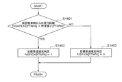
図14に示されるように、本第3実施形態では、前回駐車時からの走行距離DISAPEXE[PTNPA]がある所定値β[PTNPA]より大きいか否かを判定し(S1401)、所定値β[PTNPA]より大きい場合、目標車速増加判定フラグを立てる(すなわち、目標車速増加判定fVSPIOK[PTNPA]を1とする)(S1402)。所定値β[PTNPA]以下の場合、目標車速増加判定フラグを立てない(すなわち、目標車速増加判定fVSPIOK[PTNPA]を0とする)
(S1403)。なお、ここでは、前回駐車時からの走行距離DISAPEXE[PTNPA]、判定のための所定値β[PTNPA]は、駐車パターンPTNPA毎に設定される。すなわち、本第3実施形態では、前回駐車時からの走行距離が長いときは運転者は運転に慣れていると考えられるため、その場合は、上限車速(目標車速上限値)を増加させ、駐車時における当該車両の車速を増加させる。
(S1403)。なお、ここでは、前回駐車時からの走行距離DISAPEXE[PTNPA]、判定のための所定値β[PTNPA]は、駐車パターンPTNPA毎に設定される。すなわち、本第3実施形態では、前回駐車時からの走行距離が長いときは運転者は運転に慣れていると考えられるため、その場合は、上限車速(目標車速上限値)を増加させ、駐車時における当該車両の車速を増加させる。
これによっても、上記第1実施形態と同様、運転者が感じる煩わしさを低減することが可能となる。
(第4実施形態)
次に、図15を参照して、本発明に係る駐車支援装置の第4実施形態について説明する。本第4実施形態は、上述の第1実施形態における図9で示した目標車速上限値演算の他の方法であり、主に、ブレーキSWのon/off判定を加えたものである。その他の構成については、上記第1実施形態と同様であるため、その詳細説明を省略する。
次に、図15を参照して、本発明に係る駐車支援装置の第4実施形態について説明する。本第4実施形態は、上述の第1実施形態における図9で示した目標車速上限値演算の他の方法であり、主に、ブレーキSWのon/off判定を加えたものである。その他の構成については、上記第1実施形態と同様であるため、その詳細説明を省略する。
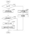
図15に示されるように、本第4実施形態では、駐車開始後にブレーキSWのon/off判定を加えることで、駐車中のブレーキ操作により車速の上限値(目標車速上限値)を制限したあと(すなわち、駐車時における車両の車速を減速側に補正したあと)、ブレーキ操作が無いときに、車速の上限値を増加させる(戻す)ようにしている。
具体的には、駐車開始後のブレーキSWのon/offを判定し(S1501)、ブレーキSWがonの場合、ブレーキON時目標車速上限値TVspLMTを演算して駐車中のブレーキ操作により車速の上限値を制限するとともに(S1506)、そのときの最大減速度GMAXを記憶する(S1507)。一方、ブレーキSWがoffの場合、目標車速増加判定fVSPIOK[PTNPA]を演算し(S1502)、その演算の結果、目標車速増加要の場合は(S1503)、増加量DTVspLMTを演算し(S1504)、ブレーキ操作が無いときの目標車速上限値TVspLMTの増加量DTVspLMTを最大減速度GMAXに応じた補正GAIN[GMAX]で補正(変更)して目標車速上限値TVspLMTを設定し直す(S1505)。本例では、最大減速度GMAXが大きくなるに従って補正GAINを小さく設定する(すなわち、車両の車速の増加量DTVspLMTを小さくする)ことで、急減速後の目標車速上限値の増加量を小さく補正し、緩減速後の目標車速上限値の増加量を大きく補正する。
これにより、運転者が感じる煩わしさをより精緻に低減することが可能となる。
以上で説明したように、本実施形態によれば、例えば、運転者のブレーキ操作、前回駐車時からの経過時間、前回駐車時からの走行距離、駐車時の減速度などといった、車両の駐車時もしくは前回駐車時からの挙動に応じて駐車時における車両の車速を増加させることで、例えば自動駐車制御を使い始めで車両の目標車速が減速側に補正されたあとに、自動駐車制御の慣れにより運転者が感じる煩わしさを低減することが可能となる。
なお、上記第1~第4実施形態では、例えば、運転者のブレーキ操作、前回駐車時からの経過時間、前回駐車時からの走行距離、駐車時の減速度などの車両挙動に基づいて目標車速上限値を含む車速の増加を判定しているが、上記以外の車両挙動で目標車速上限値を含む車速の増加を判定しても良いことは勿論である。
なお、本発明は上記した第1~第4実施形態に限定されるものではなく、様々な変形形態が含まれる。例えば、上記した第1~第4実施形態は本発明を分かりやすく説明するために詳細に説明したものであり、必ずしも説明した全ての構成を備えるものに限定されるものではない。また、ある実施形態の構成の一部を他の実施形態の構成に置き換えることが可能であり、また、ある実施形態の構成に他の実施形態の構成を加えることも可能である。また、各実施形態の構成の一部について、他の構成の追加・削除・置換をすることが可能である。
また、上記の各構成、機能、処理部、処理手段等は、それらの一部又は全部を、例えば集積回路で設計する等によりハードウェアで実現してもよい。また、上記の各構成、機能等は、プロセッサがそれぞれの機能を実現するプログラムを解釈し、実行することによりソフトウェアで実現してもよい。各機能を実現するプログラム、テーブル、ファイル等の情報は、メモリや、ハードディスク、SSD(Solid State Drive)等の記憶装置、または、ICカード、SDカード、DVD等の記録媒体に置くことができる。
また、制御線や情報線は説明上必要と考えられるものを示しており、製品上必ずしも全ての制御線や情報線を示しているとは限らない。実際には殆ど全ての構成が相互に接続されていると考えてもよい。
1 ・・・自動駐車システム
100・・・駐車支援装置
100i・・・入力部
100c・・・コンピュータ
100o・・・出力部
101・・・HMI装置
101a・・・駐車開始SW
102・・・外界認識入力装置
103・・・駆動力制御装置
104・・・制動力制御装置
105・・・車速入力装置
106・・・シフト制御装置
110・・・通信手段
100・・・駐車支援装置
100i・・・入力部
100c・・・コンピュータ
100o・・・出力部
101・・・HMI装置
101a・・・駐車開始SW
102・・・外界認識入力装置
103・・・駆動力制御装置
104・・・制動力制御装置
105・・・車速入力装置
106・・・シフト制御装置
110・・・通信手段
Claims (13)
- 駐車時の車両の車速を制御して該車両の駐車を支援する駐車支援装置であって、
前記車両の駐車時もしくは前回駐車時からの挙動に応じて駐車時における前記車両の車速を増加させることを特徴とする駐車支援装置。 - 前記車両の駐車時もしくは前回駐車時からの挙動に応じて駐車時における前記車両の車速の目標車速上限値を増加設定することを特徴とする、請求項1に記載の駐車支援装置。
- 前回駐車時における運転者によるブレーキ操作の有無に基づいて駐車時における前記車両の車速を増加させることを特徴とする、請求項1に記載の駐車支援装置。
- 前回駐車時までに運転者がブレーキ操作しない駐車を連続して所定回数実施した場合に、駐車時における前記車両の車速を増加させることを特徴とする、請求項3に記載の駐車支援装置。
- 駐車パターンに応じて前記所定回数を変更することを特徴とする、請求項4に記載の駐車支援装置。
- 前回駐車時からの経過時間に基づいて駐車時における前記車両の車速を増加させることを特徴とする、請求項1に記載の駐車支援装置。
- 前回駐車時からの経過時間が所定値未満である場合に、駐車時における前記車両の車速を増加させることを特徴とする、請求項6に記載の駐車支援装置。
- 前回駐車時からの走行距離に基づいて駐車時における前記車両の車速を増加させることを特徴とする、請求項1に記載の駐車支援装置。
- 前回駐車時からの走行距離が所定値より大きい場合に、駐車時における前記車両の車速を増加させることを特徴とする、請求項8に記載の駐車支援装置。
- 駐車パターンに応じて前記車両の車速の増加量を変更することを特徴とする、請求項1に記載の駐車支援装置。
- 駐車時における前記車両の車速が減速側に補正されている場合に、前記車両の駐車時もしくは前回駐車時からの挙動に応じて駐車時における前記車両の車速を増加させることを特徴とする、請求項1に記載の駐車支援装置。
- 前回駐車時の減速度に応じて前記車両の車速の増加量を変更することを特徴とする、請求項1に記載の駐車支援装置。
- 前回駐車時の減速度が大きくなるに従って前記車両の車速の増加量を小さくすることを特徴とする、請求項12に記載の駐車支援装置。
Priority Applications (3)
| Application Number | Priority Date | Filing Date | Title |
|---|---|---|---|
| US16/622,148 US11173896B2 (en) | 2017-06-16 | 2018-04-26 | Parking assistance device |
| EP18817660.6A EP3597499B1 (en) | 2017-06-16 | 2018-04-26 | Parking assistance device |
| JP2019525182A JP6838255B2 (ja) | 2017-06-16 | 2018-04-26 | 駐車支援装置 |
Applications Claiming Priority (2)
| Application Number | Priority Date | Filing Date | Title |
|---|---|---|---|
| JP2017-118907 | 2017-06-16 | ||
| JP2017118907 | 2017-06-16 |
Publications (1)
| Publication Number | Publication Date |
|---|---|
| WO2018230175A1 true WO2018230175A1 (ja) | 2018-12-20 |
Family
ID=64660967
Family Applications (1)
| Application Number | Title | Priority Date | Filing Date |
|---|---|---|---|
| PCT/JP2018/016923 Ceased WO2018230175A1 (ja) | 2017-06-16 | 2018-04-26 | 駐車支援装置 |
Country Status (4)
| Country | Link |
|---|---|
| US (1) | US11173896B2 (ja) |
| EP (1) | EP3597499B1 (ja) |
| JP (1) | JP6838255B2 (ja) |
| WO (1) | WO2018230175A1 (ja) |
Cited By (1)
| Publication number | Priority date | Publication date | Assignee | Title |
|---|---|---|---|---|
| JP2020164065A (ja) * | 2019-03-29 | 2020-10-08 | パナソニックIpマネジメント株式会社 | 車両制御装置、車両、車両制御方法、及び車両制御プログラム |
Families Citing this family (4)
| Publication number | Priority date | Publication date | Assignee | Title |
|---|---|---|---|---|
| CN109969171A (zh) * | 2017-12-26 | 2019-07-05 | 罗伯特·博世有限公司 | 车库模式控制单元、控制系统和控制方法 |
| CN111806430B (zh) * | 2020-06-03 | 2021-12-31 | 惠州市德赛西威汽车电子股份有限公司 | 一种用于自动泊车的车速计算方法 |
| CN112026753B (zh) * | 2020-08-27 | 2022-01-07 | 重庆长安汽车股份有限公司 | 一种低速场景中稳定车速控制方法 |
| CN115214726B (zh) * | 2021-04-19 | 2025-05-13 | 比亚迪股份有限公司 | 车辆停车控制方法及装置 |
Citations (4)
| Publication number | Priority date | Publication date | Assignee | Title |
|---|---|---|---|---|
| JP2010501394A (ja) * | 2006-08-23 | 2010-01-21 | ローベルト ボツシユ ゲゼルシヤフト ミツト ベシユレンクテル ハフツング | ドライバーアシストシステム |
| JP2013082376A (ja) * | 2011-10-12 | 2013-05-09 | Denso Corp | 駐車支援装置 |
| JP2014024462A (ja) * | 2012-07-27 | 2014-02-06 | Nissan Motor Co Ltd | 駐車支援装置 |
| JP2016150593A (ja) | 2015-02-16 | 2016-08-22 | 三菱電機株式会社 | 車両制御装置および車両制御方法 |
Family Cites Families (2)
| Publication number | Priority date | Publication date | Assignee | Title |
|---|---|---|---|---|
| DE102008041681A1 (de) | 2008-08-29 | 2010-03-04 | Robert Bosch Gmbh | Steuereinrichtung und Verfahren zur Durchführung eines automatischen Einparkvorgangs |
| US10293816B2 (en) * | 2014-09-10 | 2019-05-21 | Ford Global Technologies, Llc | Automatic park and reminder system and method of use |
-
2018
- 2018-04-26 JP JP2019525182A patent/JP6838255B2/ja active Active
- 2018-04-26 US US16/622,148 patent/US11173896B2/en active Active
- 2018-04-26 EP EP18817660.6A patent/EP3597499B1/en active Active
- 2018-04-26 WO PCT/JP2018/016923 patent/WO2018230175A1/ja not_active Ceased
Patent Citations (4)
| Publication number | Priority date | Publication date | Assignee | Title |
|---|---|---|---|---|
| JP2010501394A (ja) * | 2006-08-23 | 2010-01-21 | ローベルト ボツシユ ゲゼルシヤフト ミツト ベシユレンクテル ハフツング | ドライバーアシストシステム |
| JP2013082376A (ja) * | 2011-10-12 | 2013-05-09 | Denso Corp | 駐車支援装置 |
| JP2014024462A (ja) * | 2012-07-27 | 2014-02-06 | Nissan Motor Co Ltd | 駐車支援装置 |
| JP2016150593A (ja) | 2015-02-16 | 2016-08-22 | 三菱電機株式会社 | 車両制御装置および車両制御方法 |
Non-Patent Citations (1)
| Title |
|---|
| See also references of EP3597499A4 |
Cited By (2)
| Publication number | Priority date | Publication date | Assignee | Title |
|---|---|---|---|---|
| JP2020164065A (ja) * | 2019-03-29 | 2020-10-08 | パナソニックIpマネジメント株式会社 | 車両制御装置、車両、車両制御方法、及び車両制御プログラム |
| WO2020203130A1 (ja) * | 2019-03-29 | 2020-10-08 | パナソニックIpマネジメント株式会社 | 車両制御装置、車両、及び車両制御方法 |
Also Published As
| Publication number | Publication date |
|---|---|
| EP3597499A1 (en) | 2020-01-22 |
| EP3597499B1 (en) | 2023-01-18 |
| EP3597499A4 (en) | 2020-12-23 |
| JPWO2018230175A1 (ja) | 2020-03-19 |
| JP6838255B2 (ja) | 2021-03-03 |
| US11173896B2 (en) | 2021-11-16 |
| US20200122718A1 (en) | 2020-04-23 |
Similar Documents
| Publication | Publication Date | Title |
|---|---|---|
| WO2018230175A1 (ja) | 駐車支援装置 | |
| RU2696893C2 (ru) | Система и способ параллельной парковки транспортного средства | |
| JP7186057B2 (ja) | 車両制御装置 | |
| JP7488632B2 (ja) | 操舵制御装置 | |
| US20210173531A1 (en) | Display control device, vehicle, display control method, and strage medium storing program | |
| JP2020147220A (ja) | 車両制御装置 | |
| US10919542B2 (en) | Apparatus and method for providing a kinesthetic cue in a driving automation equipped vehicle | |
| CN110316191B (zh) | 车辆控制装置 | |
| CN115195718A (zh) | 一种车道保持辅助驾驶方法、系统及电子设备 | |
| JP7133752B2 (ja) | 走行制御装置 | |
| CN115140056A (zh) | 车辆控制装置 | |
| JP7204873B2 (ja) | 車両制御装置、車両制御方法及び車両制御システム | |
| JP7107281B2 (ja) | 情報提示制御装置 | |
| US20250136107A1 (en) | Vehicle control device | |
| KR20140142444A (ko) | 주차공간 탐색 장치 및 자동 주차 제어 시스템 | |
| JP2008155815A (ja) | 走行制御装置 | |
| US12280669B2 (en) | Vehicular display control device, vehicular display device, vehicular display control method, and non-transitory computer-readable recording medium recorded with program | |
| JP7394303B2 (ja) | 駐車支援装置 | |
| JP6601679B2 (ja) | 判定装置、判定方法、および判定プログラム | |
| JP7415422B2 (ja) | 駐車支援装置 | |
| JP7434796B2 (ja) | 駐車支援装置、駐車支援方法、および駐車支援プログラム | |
| KR102665460B1 (ko) | 가변형 flex brake 시스템 | |
| JP7514153B2 (ja) | 駐車支援装置 | |
| WO2025013722A1 (ja) | 車両用制御装置及び車両用制御方法 | |
| JP2024071955A (ja) | 駐車支援装置及び駐車支援方法 |
Legal Events
| Date | Code | Title | Description |
|---|---|---|---|
| 121 | Ep: the epo has been informed by wipo that ep was designated in this application |
Ref document number: 18817660 Country of ref document: EP Kind code of ref document: A1 |
|
| ENP | Entry into the national phase |
Ref document number: 2019525182 Country of ref document: JP Kind code of ref document: A |
|
| ENP | Entry into the national phase |
Ref document number: 2018817660 Country of ref document: EP Effective date: 20191016 |
|
| NENP | Non-entry into the national phase |
Ref country code: DE |