WO2018230300A1 - 通信装置、通信方法及びコンピュータプログラム - Google Patents
通信装置、通信方法及びコンピュータプログラム Download PDFInfo
- Publication number
- WO2018230300A1 WO2018230300A1 PCT/JP2018/020090 JP2018020090W WO2018230300A1 WO 2018230300 A1 WO2018230300 A1 WO 2018230300A1 JP 2018020090 W JP2018020090 W JP 2018020090W WO 2018230300 A1 WO2018230300 A1 WO 2018230300A1
- Authority
- WO
- WIPO (PCT)
- Prior art keywords
- transmission
- communication
- multiple access
- orthogonal multiple
- information
- Prior art date
- Legal status (The legal status is an assumption and is not a legal conclusion. Google has not performed a legal analysis and makes no representation as to the accuracy of the status listed.)
- Ceased
Links
Images










Classifications
-
- H—ELECTRICITY
- H04—ELECTRIC COMMUNICATION TECHNIQUE
- H04L—TRANSMISSION OF DIGITAL INFORMATION, e.g. TELEGRAPHIC COMMUNICATION
- H04L5/00—Arrangements affording multiple use of the transmission path
- H04L5/0091—Signalling for the administration of the divided path, e.g. signalling of configuration information
-
- H—ELECTRICITY
- H04—ELECTRIC COMMUNICATION TECHNIQUE
- H04L—TRANSMISSION OF DIGITAL INFORMATION, e.g. TELEGRAPHIC COMMUNICATION
- H04L5/00—Arrangements affording multiple use of the transmission path
- H04L5/003—Arrangements for allocating sub-channels of the transmission path
- H04L5/0053—Allocation of signalling, i.e. of overhead other than pilot signals
-
- H—ELECTRICITY
- H04—ELECTRIC COMMUNICATION TECHNIQUE
- H04L—TRANSMISSION OF DIGITAL INFORMATION, e.g. TELEGRAPHIC COMMUNICATION
- H04L27/00—Modulated-carrier systems
- H04L27/26—Systems using multi-frequency codes
-
- H—ELECTRICITY
- H04—ELECTRIC COMMUNICATION TECHNIQUE
- H04L—TRANSMISSION OF DIGITAL INFORMATION, e.g. TELEGRAPHIC COMMUNICATION
- H04L5/00—Arrangements affording multiple use of the transmission path
- H04L5/0001—Arrangements for dividing the transmission path
- H04L5/0028—Variable division
-
- H—ELECTRICITY
- H04—ELECTRIC COMMUNICATION TECHNIQUE
- H04L—TRANSMISSION OF DIGITAL INFORMATION, e.g. TELEGRAPHIC COMMUNICATION
- H04L5/00—Arrangements affording multiple use of the transmission path
- H04L5/0091—Signalling for the administration of the divided path, e.g. signalling of configuration information
- H04L5/0092—Indication of how the channel is divided
-
- H—ELECTRICITY
- H04—ELECTRIC COMMUNICATION TECHNIQUE
- H04W—WIRELESS COMMUNICATION NETWORKS
- H04W72/00—Local resource management
- H04W72/04—Wireless resource allocation
-
- H—ELECTRICITY
- H04—ELECTRIC COMMUNICATION TECHNIQUE
- H04W—WIRELESS COMMUNICATION NETWORKS
- H04W72/00—Local resource management
- H04W72/20—Control channels or signalling for resource management
- H04W72/23—Control channels or signalling for resource management in the downlink direction of a wireless link, i.e. towards a terminal
Definitions
- the present disclosure relates to a communication device, a communication method, and a computer program.
- LTE Long Term Evolution
- LTE-A Long Term Evolution
- LTE-A Pro LTE-Advanced Pro
- NR New Radio
- NRAT New Radio Access Technology
- EUTRA Evolved Universal Terrestrial Access
- FEUTRA3 Partner 3GPP
- LTE includes LTE-A, LTE-A Pro, and EUTRA
- NR includes NRAT and FEUTRA.
- LTE and NR a base station device (base station) is also referred to as eNodeB (evolved NodeB), and a terminal device (mobile station, mobile station device, terminal) is also referred to as UE (User Equipment).
- eNodeB evolved NodeB
- UE User Equipment
- LTE and NR are cellular communication systems in which a plurality of areas covered by a base station apparatus are arranged in a cell shape.
- a single base station apparatus may manage a plurality of cells.
- NR is a RAT (Radio Access Technology) different from LTE as a next-generation radio access method for LTE.
- NR is an eMBB (Enhanced mobile broadband), mMTC (Massive machine type communications), and URLLC (Ultra reliable and low latency communications) and can be used in various use cases.
- NR is examined with the aim of a technology framework that addresses usage scenarios, requirements, and deployment scenarios in those use cases. In NR, further improvement in frequency utilization efficiency is required for reasons such as the maximum data rate support about 20 times that of LTE and the simultaneous communication support of about 10 times the number of terminals.
- NOMA Non-orthogonal multiple access
- NR is required to perform communication with higher frequency utilization efficiency than LTE in order to cope with various use cases.
- the present disclosure has been made in view of the above problems, and the purpose of the present disclosure is to flexibly design according to various use cases in a communication system in which a base station device and a terminal device communicate with each other. It is an object of the present invention to provide a new and improved communication apparatus, communication method, and computer program capable of greatly improving transmission efficiency.
- an acquisition unit that acquires information from a device that performs wireless communication, and an orthogonal multiple access communication and a non-orthogonal multiple access communication for communication with the device based on the information acquired by the acquisition unit.
- a communication device comprising a control unit that selects one of them.
- a communication method includes selecting and executing by the processor.
- the computer acquires information from a device that performs wireless communication, and communication with the device based on the acquired information includes orthogonal multiple access communication and non-orthogonal multiple access communication.
- a computer program is provided that allows the user to select either one of the two.
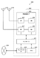
- FIG. 24 is a block diagram illustrating an example of a schematic configuration of a car navigation device 920 to which the technology according to the present disclosure can be applied.
- the wireless communication system includes at least a base station device 1 and a terminal device 2.
- the base station device 1 can accommodate a plurality of terminal devices.
- the base station device 1 can be connected to other base station devices by means of an X2 interface.
- the base station apparatus 1 can be connected to an EPC (Evolved Packet Core) by means of an S1 interface.
- the base station apparatus 1 can be connected to an MME (Mobility Management Entity) by means of an S1-MME interface, and can be connected to an S-GW (Serving Gateway) by means of an S1-U interface.
- the S1 interface supports a many-to-many connection between the MME and / or S-GW and the base station apparatus 1.
- the base station apparatus 1 and the terminal device 2 support LTE and / or NR, respectively.
- each of the base station device 1 and the terminal device 2 supports one or more radio access technologies (RAT).
- RAT includes LTE and NR.
- One RAT corresponds to one cell (component carrier). That is, when multiple RATs are supported, each RAT corresponds to a different cell.
- a cell is a combination of downlink resources, uplink resources, and / or side links.
- LTE Long Term Evolution
- NR New Radio Access
- Downlink communication is communication from the base station device 1 to the terminal device 2.
- Uplink communication is communication from the terminal device 2 to the base station device 1.
- the side link communication is communication from the terminal device 2 to another terminal device 2.
- Side link communication is defined for proximity direct detection and proximity direct communication between terminal devices.
- the side link communication can use the same frame configuration as the uplink and downlink. Further, side link communication may be limited to a part (subset) of uplink resources and / or downlink resources.
- the base station apparatus 1 and the terminal apparatus 2 can support communication using a set of one or more cells in the downlink, uplink, and / or side link.
- a set of a plurality of cells is also referred to as carrier aggregation or dual connectivity. Details of carrier aggregation and dual connectivity will be described later.
- Each cell uses a predetermined frequency bandwidth. The maximum value, minimum value, and settable value in a predetermined frequency bandwidth can be defined in advance.
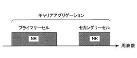
- FIG. 1 is a diagram showing an example of component carrier settings in the present embodiment.
- one LTE cell and two NR cells are set.
- One LTE cell is set as a primary cell.
- the two NR cells are set as a primary secondary cell and a secondary cell, respectively.
- the two NR cells are integrated by carrier aggregation.
- the LTE cell and the NR cell are integrated by dual connectivity. Note that the LTE cell and the NR cell may be integrated by carrier aggregation.
- the NR since the NR can be assisted by the LTE cell that is the primary cell, the NR may not support some functions such as a function for performing stand-alone communication.
- the function for stand-alone communication includes a function necessary for initial connection.
- FIG. 2 is a diagram illustrating an example of component carrier settings in the present embodiment.
- two NR cells are set.
- the two NR cells are set as a primary cell and a secondary cell, respectively, and are integrated by carrier aggregation.
- the support of the LTE cell becomes unnecessary by supporting the function for the NR cell to perform stand-alone communication.
- the two NR cells may be integrated by dual connectivity.
- a radio frame composed of 10 ms (milliseconds) is defined.
- Each radio frame is composed of two half frames.
- the time interval of the half frame is 5 ms.
- Each half frame is composed of five subframes.
- the subframe time interval is 1 ms and is defined by two consecutive slots.
- the slot time interval is 0.5 ms.
- the i-th subframe in the radio frame is composed of a (2 ⁇ i) th slot and a (2 ⁇ i + 1) th slot. That is, 10 subframes are defined in each radio frame.
- the subframe includes a downlink subframe, an uplink subframe, a special subframe, a sidelink subframe, and the like.
- the downlink subframe is a subframe reserved for downlink transmission.
- An uplink subframe is a subframe reserved for uplink transmission.
- the special subframe is composed of three fields. The three fields include DwPTS (Downlink Pilot Time Slot), GP (Guard Period), and UpPTS (Uplink Pilot Time Slot). The total length of DwPTS, GP, and UpPTS is 1 ms.
- DwPTS is a field reserved for downlink transmission.
- UpPTS is a field reserved for uplink transmission.
- GP is a field in which downlink transmission and uplink transmission are not performed. Note that the special subframe may be configured only by DwPTS and GP, or may be configured only by GP and UpPTS.
- the special subframe is arranged between the downlink subframe and the uplink subframe in TDD, and is used for switching from the downlink subframe to the uplink subframe.
- the side link subframe is a subframe reserved or set for side link communication.
- the side link is used for proximity direct communication and proximity direct detection between terminal devices.
- a single radio frame includes a downlink subframe, an uplink subframe, a special subframe, and / or a sidelink subframe. Also, a single radio frame may be composed of only downlink subframes, uplink subframes, special subframes, or sidelink subframes.
- the radio frame configuration is defined by the frame configuration type.
- Frame configuration type 1 is applicable only to FDD.
- Frame configuration type 2 is applicable only to TDD.
- Frame configuration type 3 is applicable only to operation of LAA (Licensed Assisted Access) secondary cells.
- each of the 10 subframes in one radio frame corresponds to one of a downlink subframe, an uplink subframe, and a special subframe.
- Subframe 0, subframe 5 and DwPTS are always reserved for downlink transmission.
- the subframe immediately following UpPTS and its special subframe is always reserved for uplink transmission.
- the terminal device 2 can handle a subframe in which no PDSCH or detection signal is transmitted as an empty subframe.
- the terminal apparatus 2 assumes that no signal and / or channel exists in the subframe unless a predetermined signal, channel and / or downlink transmission is detected in the subframe.
- Downlink transmission is dedicated in one or more consecutive subframes.
- the first subframe of the downlink transmission may start from anywhere within that subframe.
- the last subframe of the downlink transmission may be either completely occupied or dedicated at a time interval defined by DwPTS.
- 10 subframes in one radio frame may be reserved for uplink transmission. Further, each of the 10 subframes in one radio frame may correspond to any of a downlink subframe, an uplink subframe, a special subframe, and a sidelink subframe.
- the base station apparatus 1 may transmit a physical downlink channel and a physical downlink signal in DwPTS of the special subframe.
- the base station apparatus 1 can restrict PBCH transmission in DwPTS of the special subframe.
- the terminal device 2 may transmit the physical uplink channel and the physical uplink signal in the UpPTS of the special subframe.
- the terminal device 2 can restrict transmission of some physical uplink channels and physical uplink signals in the UpPTS of the special subframe.
- ⁇ Frame structure of NR in this embodiment> In each of the NR cells, one or more predetermined parameters are used in a certain predetermined time length (for example, subframe). That is, in the NR cell, the downlink signal and the uplink signal are each generated with one or more predetermined parameters in a predetermined time length.
- the terminal apparatus 2 generates a downlink signal transmitted from the base station apparatus 1 and an uplink signal transmitted to the base station apparatus 1 with one or more predetermined parameters in a predetermined time length.
- the base station apparatus 1 generates a downlink signal to be transmitted to the terminal apparatus 2 and an uplink signal to be transmitted from the terminal apparatus 2 with one or more predetermined parameters for each predetermined time length.
- the predetermined method includes FDM (Frequency Division Multiplexing), TDM (Time Division Multiplexing), CDM (Code Division Multiplexing), and / or SDM (Spatial Division Multiplexing).
- FDM Frequency Division Multiplexing
- TDM Time Division Multiplexing
- CDM Code Division Multiplexing
- SDM Spatial Division Multiplexing
- a plurality of types of combinations of predetermined parameters set in the NR cell can be specified in advance as a parameter set.
- FIG. 3 is a diagram illustrating an example of a parameter set related to a transmission signal in the NR cell.
- the parameters related to the transmission signal included in the parameter set are the subframe interval, the number of subcarriers per resource block in the NR cell, the number of symbols per subframe, and the CP length type.
- the CP length type is a CP length type used in the NR cell.
- CP length type 1 corresponds to a normal CP in LTE
- CP length type 2 corresponds to an extended CP in LTE.
- Parameter sets related to transmission signals in the NR cell can be individually defined for the downlink and uplink. Also, parameter sets related to transmission signals in the NR cell can be set independently for the downlink and uplink.
- FIG. 4 is a diagram illustrating an example of an NR downlink subframe in the present embodiment.
- a signal generated using parameter set 1, parameter set 0, and parameter set 2 is FDM in a cell (system bandwidth).
- the diagram shown in FIG. 4 is also referred to as the NR downlink resource grid.
- the base station apparatus 1 can transmit an NR physical downlink channel and / or an NR physical downlink signal in a downlink subframe to the terminal apparatus 2.
- the terminal device 2 can receive the NR physical downlink channel and / or the NR physical downlink signal in the downlink subframe from the base station device 1.
- FIG. 5 is a diagram illustrating an example of an uplink subframe of NR in the present embodiment.
- a signal generated using parameter set 1, parameter set 0, and parameter set 2 is FDM in a cell (system bandwidth).
- the diagram shown in FIG. 5 is also referred to as the NR uplink resource grid.
- the base station apparatus 1 can transmit an NR physical uplink channel and / or an NR physical uplink signal in an uplink subframe to the terminal apparatus 2.
- the terminal apparatus 2 can receive the NR physical uplink channel and / or the NR physical uplink signal in the uplink subframe from the base station apparatus 1.
- FIG. 6 is a schematic block diagram illustrating the configuration of the base station device 1 of the present embodiment.
- the base station apparatus 1 includes an upper layer processing unit 101, a control unit 103, a receiving unit 105, a transmitting unit 107, and a transmission / reception antenna 109.
- the reception unit 105 includes a decoding unit 1051, a demodulation unit 1053, a demultiplexing unit 1055, a radio reception unit 1057, and a channel measurement unit 1059.
- the transmission unit 107 includes an encoding unit 1071, a modulation unit 1073, a multiplexing unit 1075, a radio transmission unit 1077, and a downlink reference signal generation unit 1079.
- the base station apparatus 1 can support one or more RATs. Some or all of the units included in the base station apparatus 1 shown in FIG. 6 can be individually configured according to the RAT. For example, the reception unit 105 and the transmission unit 107 are individually configured with LTE and NR. Further, in the NR cell, a part or all of each unit included in the base station apparatus 1 shown in FIG. 6 can be individually configured according to a parameter set related to a transmission signal. For example, in a certain NR cell, the radio reception unit 1057 and the radio transmission unit 1077 can be individually configured according to a parameter set regarding a transmission signal.
- the upper layer processing unit 101 includes a medium access control (MAC) layer, a packet data integration protocol (Packet Data Convergence Protocol: PDCP) layer, a radio link control (Radio Link Control: RLC) layer, a radio resource control (Radio). Process Resource Control: RRC) layer. Further, the upper layer processing unit 101 generates control information for controlling the reception unit 105 and the transmission unit 107 and outputs the control information to the control unit 103.
- MAC medium access control
- PDCP Packet Data Convergence Protocol
- RLC Radio Link Control
- Radio Radio
- RRC Radio Resource Control
- the control unit 103 controls the reception unit 105 and the transmission unit 107 based on the control information from the higher layer processing unit 101.
- the control unit 103 generates control information for the upper layer processing unit 101 and outputs the control information to the upper layer processing unit 101.
- the control unit 103 inputs the decoded signal from the decoding unit 1051 and the channel estimation result from the channel measurement unit 1059.
- the control unit 103 outputs a signal to be encoded to the encoding unit 1071.
- the control unit 103 is used to control all or part of the base station apparatus 1.
- the upper layer processing unit 101 performs processing and management related to RAT control, radio resource control, subframe setting, scheduling control, and / or CSI report control.
- the processing and management in the upper layer processing unit 101 is performed for each terminal device or for the terminal devices connected to the base station device.
- the processing and management in the upper layer processing unit 101 may be performed only by the upper layer processing unit 101, or may be acquired from an upper node or another base station device. Further, the processing and management in the upper layer processing unit 101 may be performed individually according to the RAT. For example, the upper layer processing unit 101 individually performs processing and management in LTE and processing and management in NR.
- management related to RAT is performed.
- management related to LTE and / or management related to NR is performed.
- Management regarding NR includes setting and processing of parameter sets regarding transmission signals in the NR cell.
- radio resource control in the upper layer processing unit 101, generation and / or management of downlink data (transport block), system information, RRC message (RRC parameter), and / or MAC control element (CE) is performed. Done.
- subframe setting in the upper layer processing unit 101 subframe setting, subframe pattern setting, uplink-downlink setting, uplink reference UL-DL setting, and / or downlink reference UL-DL setting are managed. Is called.
- the subframe setting in higher layer processing section 101 is also referred to as base station subframe setting.
- the subframe setting in the higher layer processing unit 101 can be determined based on the uplink traffic volume and the downlink traffic volume. Further, the subframe setting in the upper layer processing unit 101 can be determined based on the scheduling result of the scheduling control in the upper layer processing unit 101.
- the frequency and subframe to which a physical channel is allocated, the physical channel's A coding rate, a modulation scheme, transmission power, and the like are determined.
- the control unit 103 generates control information (DCI format) based on the scheduling result of scheduling control in the upper layer processing unit 101.
- the CSI report of the terminal device 2 is controlled.
- the setting related to the CSI reference resource to be assumed for calculating the CSI in the terminal device 2 is controlled.
- the receiving unit 105 receives a signal transmitted from the terminal device 2 via the transmission / reception antenna 109 in accordance with control from the control unit 103, further performs reception processing such as separation, demodulation, and decoding, and receives the received information. Output to the control unit 103. Note that the reception process in the reception unit 105 is performed based on a setting specified in advance or a setting notified from the base station apparatus 1 to the terminal apparatus 2.
- the radio reception unit 1057 converts the uplink signal received via the transmission / reception antenna 109 into an intermediate frequency (down-conversion), removes unnecessary frequency components, and appropriately maintains the signal level. Control of amplification level, quadrature demodulation based on in-phase and quadrature components of received signal, conversion from analog signal to digital signal, removal of guard interval (GI), and / or fast Fourier transform (Fast Fourier transform) Extract frequency domain signals by Transform: FFT).
- GI guard interval
- FFT fast Fourier transform
- the demultiplexing unit 1055 separates an uplink channel such as PUCCH or PUSCH and / or an uplink reference signal from the signal input from the radio reception unit 1057.
- the demultiplexing unit 1055 outputs the uplink reference signal to the channel measurement unit 1059.
- the demultiplexing unit 1055 performs channel compensation for the uplink channel from the channel estimation value input from the channel measurement unit 1059.
- the demodulation unit 1053 receives a received signal using a modulation scheme such as BPSK (Binary Phase Shift Keying), QPSK (Quadrature Phase Shift Keying), 16QAM (Quadrature Amplitude Modulation), 64QAM, or 256QAM for the modulation symbol of the uplink channel. Is demodulated.
- Demodulation section 1053 separates and demodulates the MIMO multiplexed uplink channel.
- the decoding unit 1051 performs a decoding process on the demodulated uplink channel encoded bits.
- the decoded uplink data and / or uplink control information is output to the control unit 103.
- Decoding section 1051 performs decoding processing for each transport block for PUSCH.
- the channel measurement unit 1059 measures the propagation path estimation value and / or channel quality from the uplink reference signal input from the demultiplexing unit 1055, and outputs it to the demultiplexing unit 1055 and / or the control unit 103.
- UL-DMRS measures a channel estimation value for channel compensation for PUCCH or PUSCH
- SRS measures channel quality in the uplink.
- the transmission unit 107 performs transmission processing such as encoding, modulation, and multiplexing on the downlink control information and the downlink data input from the higher layer processing unit 101 according to the control from the control unit 103. For example, the transmission unit 107 generates and multiplexes PHICH, PDCCH, EPDCCH, PDSCH, and a downlink reference signal, and generates a transmission signal. Note that the transmission processing in the transmission unit 107 is based on settings specified in advance, settings notified from the base station apparatus 1 to the terminal apparatus 2, or settings notified via the PDCCH or EPDCCH transmitted in the same subframe. Done.
- the encoding unit 1071 performs HARQ indicator (HARQ-ACK), downlink control information, and downlink data input from the control unit 103 with predetermined encoding such as block encoding, convolutional encoding, and turbo encoding. Encoding is performed using a method.
- the modulation unit 1073 modulates the coded bits input from the coding unit 1071 with a predetermined modulation method such as BPSK, QPSK, 16QAM, 64QAM, 256QAM.
- the downlink reference signal generation unit 1079 generates a downlink reference signal based on a physical cell identifier (PCI), an RRC parameter set in the terminal device 2, and the like.
- Multiplexer 1075 multiplexes the modulation symbols and downlink reference signals for each channel and arranges them in a predetermined resource element.
- the radio transmission unit 1077 converts the signal from the multiplexing unit 1075 into a time-domain signal by inverse fast Fourier transform (IFFT), adds a guard interval, generates a baseband digital signal, Performs conversion to analog signal, quadrature modulation, conversion from intermediate frequency signal to high frequency signal (up-convert), removal of excess frequency components, power amplification, etc. to generate a transmission signal .
- IFFT inverse fast Fourier transform
- the transmission signal output from the wireless transmission unit 1077 is transmitted from the transmission / reception antenna 109.
- FIG. 7 is a schematic block diagram showing the configuration of the terminal device 2 of the present embodiment.
- the terminal device 2 includes an upper layer processing unit 201, a control unit 203, a reception unit 205, a transmission unit 207, and a transmission / reception antenna 209.
- the reception unit 205 includes a decoding unit 2051, a demodulation unit 2053, a demultiplexing unit 2055, a radio reception unit 2057, and a channel measurement unit 2059.
- the transmission unit 207 includes an encoding unit 2071, a modulation unit 2073, a multiplexing unit 2075, a radio transmission unit 2077, and an uplink reference signal generation unit 2079.
- the terminal device 2 can support one or more RATs. Some or all of the units included in the terminal device 2 illustrated in FIG. 7 can be individually configured according to the RAT.
- the reception unit 205 and the transmission unit 207 are individually configured with LTE and NR.
- the NR cell some or all of the units included in the terminal apparatus 2 shown in FIG. 7 can be individually configured according to the parameter set related to the transmission signal.
- the radio reception unit 2057 and the radio transmission unit 2077 can be individually configured according to a parameter set related to a transmission signal.
- the higher layer processing unit 201 outputs the uplink data (transport block) to the control unit 203.
- the upper layer processing unit 201 includes a medium access control (MAC) layer, a packet data integration protocol (Packet Data Convergence Protocol: PDCP) layer, a radio link control (Radio Link Control: RLC) layer, a radio resource control (Radio). Process Resource Control: RRC) layer. Further, the upper layer processing unit 201 generates control information for controlling the reception unit 205 and the transmission unit 207 and outputs the control information to the control unit 203.
- MAC medium access control
- PDCP Packet Data Convergence Protocol
- RLC Radio Link Control
- RRC Radio Resource Control
- the control unit 203 controls the reception unit 205 and the transmission unit 207 based on the control information from the higher layer processing unit 201.
- the control unit 203 generates control information for the upper layer processing unit 201 and outputs the control information to the upper layer processing unit 201.
- the control unit 203 inputs the decoded signal from the decoding unit 2051 and the channel estimation result from the channel measurement unit 2059.
- the control unit 203 outputs a signal to be encoded to the encoding unit 2071. Further, the control unit 203 may be used to control all or part of the terminal device 2.
- the upper layer processing unit 201 performs processing and management related to RAT control, radio resource control, subframe setting, scheduling control, and / or CSI report control.
- the processing and management in the upper layer processing unit 201 are performed based on settings specified in advance and / or settings based on control information set or notified from the base station apparatus 1.
- the control information from the base station apparatus 1 includes an RRC parameter, a MAC control element, or DCI.
- the processing and management in the upper layer processing unit 201 may be performed individually according to the RAT.
- the upper layer processing unit 201 individually performs processing and management in LTE and processing and management in NR.
- management related to RAT is performed.
- management related to LTE and / or management related to NR is performed.
- Management regarding NR includes setting and processing of parameter sets regarding transmission signals in the NR cell.
- radio resource control in the higher layer processing unit 201 management of setting information in the own apparatus is performed.
- radio resource control in the upper layer processing unit 201 generation and / or management of uplink data (transport block), system information, RRC message (RRC parameter), and / or MAC control element (CE) is performed. Done.
- the subframe setting in the upper layer processing unit 201 the subframe setting in the base station apparatus 1 and / or a base station apparatus different from the base station apparatus 1 is managed.
- the subframe configuration includes uplink or downlink configuration, subframe pattern configuration, uplink-downlink configuration, uplink reference UL-DL configuration, and / or downlink reference UL-DL configuration for the subframe.
- the subframe setting in the higher layer processing unit 201 is also referred to as terminal subframe setting.
- control information for performing control related to scheduling for the reception unit 205 and the transmission unit 207 is generated based on DCI (scheduling information) from the base station apparatus 1.
- control related to CSI reporting to the base station apparatus 1 is performed.
- the channel measurement unit 2059 controls settings related to CSI reference resources that are assumed to calculate CSI.
- resources (timing) used for reporting CSI are controlled based on DCI and / or RRC parameters.
- the receiving unit 205 receives the signal transmitted from the base station apparatus 1 via the transmission / reception antenna 209 according to the control from the control unit 203, and further performs reception processing such as separation, demodulation, decoding, and the like. Is output to the control unit 203. Note that the reception process in the reception unit 205 is performed based on a predetermined setting or a notification or setting from the base station apparatus 1.
- the radio reception unit 2057 converts the uplink signal received via the transmission / reception antenna 209 to an intermediate frequency (down-conversion), removes unnecessary frequency components, and appropriately maintains the signal level. Control of amplification level, quadrature demodulation based on in-phase and quadrature components of received signal, conversion from analog signal to digital signal, removal of guard interval (GI), and / or fast Fourier transform (Fast Fourier transform) Extracts frequency domain signals using Transform (FFT).
- FFT Fast Fourier transform
- the demultiplexing unit 2055 separates a downlink channel such as PHICH, PDCCH, EPDCCH, or PDSCH, a downlink synchronization signal, and / or a downlink reference signal from the signal input from the radio reception unit 2057.
- the demultiplexing unit 2055 outputs the downlink reference signal to the channel measurement unit 2059.
- the demultiplexing unit 2055 performs channel compensation for the downlink channel from the channel estimation value input from the channel measurement unit 2059.
- the demodulator 2053 demodulates the received signal using a modulation scheme such as BPSK, QPSK, 16QAM, 64QAM, 256QAM, etc., with respect to the downlink channel modulation symbols.
- the demodulator 2053 separates and demodulates the MIMO multiplexed downlink channel.
- the decoding unit 2051 performs a decoding process on the demodulated downlink channel encoded bits.
- the decoded downlink data and / or downlink control information is output to the control unit 203.
- the decoding unit 2051 performs a decoding process for each transport block on the PDSCH.
- the channel measurement unit 2059 measures the estimated value of the propagation path and / or the channel quality from the downlink reference signal input from the demultiplexing unit 2055 and outputs it to the demultiplexing unit 2055 and / or the control unit 203.
- the downlink reference signal used for measurement by the channel measurement unit 2059 may be determined based on at least the transmission mode set by the RRC parameter and / or other RRC parameters.
- DL-DMRS measures an estimated value of a propagation path for performing propagation path compensation for PDSCH or EPDCCH.
- CRS measures a channel estimation value for performing channel compensation for PDCCH or PDSCH and / or a channel in the downlink for reporting CSI.
- CSI-RS measures the channel in the downlink for reporting CSI.
- the channel measurement unit 2059 calculates RSRP (Reference Signal Received Power) and / or RSRQ (Reference Signal Received Quality) based on the CRS, CSI-RS, or detection signal, and outputs it to the upper layer processing unit
- the transmission unit 207 performs transmission processing such as encoding, modulation, and multiplexing on the uplink control information and the uplink data input from the higher layer processing unit 201 according to the control from the control unit 203. For example, the transmission unit 207 generates and multiplexes an uplink channel such as PUSCH or PUCCH and / or an uplink reference signal, and generates a transmission signal. Note that the transmission processing in the transmission unit 207 is performed based on settings specified in advance or settings or notifications from the base station apparatus 1.
- the encoding unit 2071 encodes the HARQ indicator (HARQ-ACK), the uplink control information, and the uplink data input from the control unit 203 with predetermined encoding such as block encoding, convolutional encoding, and turbo encoding. Encoding is performed using a method.
- the modulation unit 2073 modulates the coded bits input from the coding unit 2071 using a predetermined modulation method such as BPSK, QPSK, 16QAM, 64QAM, or 256QAM.
- the uplink reference signal generation unit 2079 generates an uplink reference signal based on the RRC parameter set in the terminal device 2 and the like.
- Multiplexing section 2075 multiplexes the modulation symbols and uplink reference signals for each channel and arranges them in a predetermined resource element.
- the radio transmission unit 2077 converts the signal from the multiplexing unit 2075 into a time-domain signal by inverse fast Fourier transform (IFFT), adds a guard interval, generates a baseband digital signal, Performs conversion to analog signal, quadrature modulation, conversion from intermediate frequency signal to high frequency signal (up-convert), removal of excess frequency components, power amplification, etc. to generate a transmission signal .
- IFFT inverse fast Fourier transform
- the transmission signal output from the wireless transmission unit 2077 is transmitted from the transmission / reception antenna 209.
- the base station apparatus 1 and the terminal apparatus 2 can use various methods for control information signaling (notification, notification, and setting), respectively.
- Signaling of control information can be performed in various layers.
- the signaling of control information includes physical layer signaling that is signaling through the physical layer (layer), RRC signaling that is signaling through the RRC layer, and MAC signaling that is signaling through the MAC layer.
- the RRC signaling is dedicated RRC signaling (Dedicated RRC signaling) for notifying control information unique to the terminal device 2 or common RRC signaling (Common RRC signaling) for notifying control information unique to the base station device 1.
- Signaling used by higher layers as viewed from the physical layer, such as RRC signaling and MAC signaling is also referred to as upper layer signaling.
- RRC signaling is realized by signaling RRC parameters.
- MAC signaling is realized by signaling a MAC control element.
- Physical layer signaling is realized by signaling downlink control information (DCI: Downlink Control Information) or uplink control information (UCI: Uplink Control Information).
- DCI Downlink Control Information
- UCI Uplink Control Information
- the RRC parameter and the MAC control element are transmitted using PDSCH or PUSCH.
- DCI is transmitted using PDCCH or EPDCCH.
- UCI is transmitted using PUCCH or PUSCH.
- RRC signaling and MAC signaling are used for signaling semi-static control information and are also referred to as semi-static signaling.
- Physical layer signaling is used to signal dynamic control information and is also referred to as dynamic signaling.
- DCI is used for PDSCH scheduling or PUSCH scheduling.
- the UCI is used for CSI reporting, HARQ-ACK reporting, and / or scheduling request (SR).
- SR scheduling request
- the DCI is notified using a DCI format having a predefined field.
- predetermined information bits are mapped.
- DCI notifies downlink scheduling information, uplink scheduling information, side link scheduling information, aperiodic CSI report request, or uplink transmission power command.
- the DCI format monitored by the terminal device 2 is determined by the transmission mode set for each serving cell. That is, a part of the DCI format monitored by the terminal device 2 can be different depending on the transmission mode.
- the terminal device 2 in which the downlink transmission mode 1 is set monitors the DCI format 1A and the DCI format 1.
- the terminal device 2 in which the downlink transmission mode 4 is set monitors the DCI format 1A and the DCI format 2.
- the terminal device 2 in which the uplink transmission mode 1 is set monitors the DCI format 0.
- the terminal device 2 in which the uplink transmission mode 2 is set monitors the DCI format 0 and the DCI format 4.
- PDCCH DCI
- Cyclic Redundancy Check is added to DCI.
- the CRC is used for DCI error detection and DCI blind detection.
- CRC CRC parity bit
- RNTI Radio Network Temporary Identifier
- the terminal device 2 detects whether it is DCI for the terminal device 2 based on the RNTI. Specifically, the terminal device 2 descrambles the bit corresponding to the CRC with a predetermined RNTI, extracts the CRC, and detects whether the corresponding DCI is correct.
- RNTI is specified or set according to the purpose and application of DCI.
- RNTI is C-RNTI (Cell-RNTI), SPS C-RNTI (Semi Persistent Scheduling C-RNTI), SI-RNTI (System Information-RNTI), P-RNTI (Paging-RNTI), RA-RNTI (Random Access) -RNTI), TPC-PUCCH-RNTI (Transmit Power Control-PUCCH-RNTI), TPC-PUSCH-RNTI (Transmit Power Control-PUSCH-RNTI), Temporary C-RNTI, M-RNTI (MBMS (Multimedia Broadcast Multicastast Services) ) -RNTI) and eIMTA-RNTI.
- C-RNTI Cell-RNTI
- SPS C-RNTI Semi Persistent Scheduling C-RNTI
- SI-RNTI System Information-RNTI
- P-RNTI Paging-RNTI
- RA-RNTI Random Access
- TPC-PUCCH-RNTI
- C-RNTI and SPS C-RNTI are RNTIs specific to the terminal device 2 in the base station device 1 (cell), and are identifiers for identifying the terminal device 2.
- C-RNTI is used to schedule PDSCH or PUSCH in a certain subframe.
- the SPS C-RNTI is used to activate or release periodic scheduling of resources for PDSCH or PUSCH.
- a control channel having a CRC scrambled by SI-RNTI is used for scheduling an SIB (System Information Block).
- SIB System Information Block
- a control channel with a CRC scrambled with P-RNTI is used to control paging.
- a control channel having a CRC scrambled with RA-RNTI is used to schedule a response to RACH.
- a control channel having a CRC scrambled by TPC-PUCCH-RNTI is used for power control of PUCCH.
- a control channel having a CRC scrambled by TPC-PUSCH-RNTI is used to perform power control of PUSCH.
- a control channel having a CRC scrambled with Temporary C-RNTI is used by a mobile station apparatus for which C-RNTI is not set or recognized.
- a control channel with CRC scrambled with M-RNTI is used to schedule MBMS.
- a control channel having a CRC scrambled by eIMTA-RNTI is used for notifying information on TDD UL / DL configuration of a TDD serving cell in dynamic TDD (eIMTA). Note that the DCI format may be scrambled not only by the above RNTI but also by a new RNTI.
- Scheduling information includes information for performing scheduling in units of resource blocks or resource block groups as frequency domain scheduling.
- the resource block group is a set of consecutive resource blocks, and indicates resources allocated to terminal devices to be scheduled.
- the size of the resource block group is determined according to the system bandwidth.
- DCI is transmitted using a control channel such as PDCCH or EPDCCH.
- the terminal device 2 monitors a set of PDCCH candidates and / or a set of EPDCCH candidates of one or more activated serving cells configured by RRC signaling.
- monitoring means trying to decode PDCCH and / or EPDCCH in a set corresponding to all monitored DCI formats.
- the PDCCH candidate set or EPDCCH candidate set is also called a search space.
- a search space a shared search space (CSS) and a terminal-specific search space (USS) are defined.
- the CSS may be defined only for the search space for PDCCH.
- CSS Common Search Space
- the base station apparatus 1 maps a common control channel to a CSS among a plurality of terminal apparatuses, thereby reducing resources for transmitting the control channel.
- USS UE-specific Search Space
- the USS is a search space set using at least parameters specific to the terminal device 2. Therefore, the USS is a search space unique to the terminal device 2, and a control channel unique to the terminal device 2 can be individually transmitted. Therefore, the base station apparatus 1 can efficiently map control channels unique to a plurality of terminal apparatuses.
- USS may be set so as to be used in common by a plurality of terminal devices. Since a common USS is set for a plurality of terminal devices, parameters unique to the terminal device 2 are set so as to have the same value among the plurality of terminal devices. For example, a unit set to the same parameter among a plurality of terminal devices is a cell, a transmission point, a group of predetermined terminal devices, or the like.
- the search space for each aggregation level is defined by a set of PDCCH candidates.
- Each PDCCH is transmitted using a set of one or more CCEs (Control Channel Elements).
- the number of CCEs used for one PDCCH is also referred to as an aggregation level. For example, the number of CCEs used for one PDCCH is 1, 2, 4 or 8.
- the search space for each aggregation level is defined by a set of EPDCCH candidates.
- Each EPDCCH is transmitted using a set of one or more ECCEs (Enhanced Control Channel Elements).
- the number of ECCEs used for one EPDCCH is also referred to as an aggregation level. For example, the number of ECCEs used for one EPDCCH is 1, 2, 4, 8, 16, or 32.
- the number of PDCCH candidates or the number of EPDCCH candidates is determined based on at least the search space and the aggregation level. For example, in CSS, the number of PDCCH candidates at aggregation levels 4 and 8 is 4 and 2, respectively. For example, in USS, the numbers of PDCCH candidates in aggregations 1, 2, 4, and 8 are 6, 6, 2, and 2, respectively.
- Each ECCE is composed of multiple EREGs (Enhanced resource element groups).
- EREG is used to define the mapping of EPDCCH to resource elements.
- 16 EREGs numbered from 0 to 15, are defined. That is, EREG0 to EREG15 are defined in each RB pair.
- EREG0 to EREG15 are periodically defined by giving priority to the frequency direction with respect to resource elements other than resource elements to which predetermined signals and / or channels are mapped. For example, the resource element to which the demodulation reference signal associated with the EPDCCH transmitted through the antenna ports 107 to 110 is mapped does not define EREG.
- the number of ECCEs used for one EPDCCH depends on the EPDCCH format and is determined based on other parameters.
- the number of ECCEs used for one EPDCCH is also referred to as an aggregation level.
- the number of ECCEs used for one EPDCCH is determined based on the number of resource elements that can be used for EPDCCH transmission in one RB pair, the EPDCCH transmission method, and the like.
- the number of ECCEs used for one EPDCCH is 1, 2, 4, 8, 16, or 32.
- the number of EREGs used for one ECCE is determined based on the type of subframe and the type of cyclic prefix, and is 4 or 8. As transmission methods of EPDCCH, distributed transmission and localized transmission are supported.
- EPDCCH can use distributed transmission or local transmission.
- Distributed transmission and local transmission differ in the mapping of ECCE to EREG and RB pairs.
- one ECCE is configured using EREGs of a plurality of RB pairs.
- one ECCE is configured using one RB pair of EREGs.
- the base station apparatus 1 performs settings related to the EPDCCH for the terminal apparatus 2.
- the terminal device 2 monitors a plurality of EPDCCHs based on the setting from the base station device 1.
- a set of RB pairs with which the terminal device 2 monitors the EPDCCH can be set.
- the set of RB pairs is also referred to as an EPDCCH set or an EPDCCH-PRB set.
- One or more EPDCCH sets can be set for one terminal device 2.
- Each EPDCCH set is composed of one or more RB pairs.
- the setting regarding EPDCCH can be performed individually for each EPDCCH set.
- the base station apparatus 1 can set a predetermined number of EPDCCH sets for the terminal apparatus 2. For example, up to two EPDCCH sets can be configured as EPDCCH set 0 and / or EPDCCH set 1. Each of the EPDCCH sets can be configured with a predetermined number of RB pairs. Each EPDCCH set constitutes one set of a plurality of ECCEs. The number of ECCEs configured in one EPDCCH set is determined based on the number of RB pairs set as the EPDCCH set and the number of EREGs used for one ECCE. When the number of ECCEs configured in one EPDCCH set is N, each EPDCCH set configures ECCEs numbered from 0 to N-1. For example, when the number of EREGs used for one ECCE is 4, an EPDCCH set composed of four RB pairs constitutes 16 ECCEs.
- the terminal device 2 is configured with a plurality of cells and can perform multicarrier transmission. Communication in which the terminal device 2 uses a plurality of cells is called CA (carrier aggregation) or DC (dual connectivity). The contents described in the present embodiment can be applied to each or a part of a plurality of cells set for the terminal device 2.
- a cell set in the terminal device 2 is also referred to as a serving cell.
- a plurality of serving cells to be set include one primary cell (PCell: Primary Cell) and one or more secondary cells (SCell: Secondary Cell).
- PCell Primary Cell
- SCell Secondary Cell
- One primary cell and one or more secondary cells may be set for the terminal device 2 that supports CA.
- the primary cell is a serving cell in which an initial connection establishment procedure has been performed, a serving cell that has started a connection re-establishment procedure, or a cell designated as a primary cell in a handover procedure.
- the primary cell operates at the primary frequency.
- the secondary cell can be set after the connection is established or reconstructed.
- the secondary cell operates at the secondary frequency.
- the connection is also referred to as an RRC connection.
- DC is an operation in which a predetermined terminal device 2 consumes radio resources provided from at least two different network points.
- the network points are a master base station device (MeNB: Master eNB) and a secondary base station device (SeNB: Secondary eNB).
- the dual connectivity is that the terminal device 2 performs RRC connection at at least two network points. In dual connectivity, two network points may be connected by a non-ideal backhaul.
- a base station apparatus 1 connected to at least S1-MME (Mobility Management Entity) and serving as a mobility anchor of a core network is referred to as a master base station apparatus.
- the base station apparatus 1 that is not a master base station apparatus that provides additional radio resources to the terminal apparatus 2 is referred to as a secondary base station apparatus.
- the group of serving cells related to the master base station apparatus is also referred to as a master cell group (MCG).
- MCG master cell group
- a group of serving cells related to the secondary base station apparatus is also referred to as a secondary cell group (SCG).
- the primary cell belongs to MCG.
- SCG a secondary cell corresponding to a primary cell is referred to as a primary secondary cell (PSCell: Primary Secondary Cell).
- the PSCell base station apparatus constituting the pSCell
- the PSCell may support functions (capability, performance) equivalent to the PCell (base station apparatus constituting the PCell).
- only some functions of PCell may be supported by PSCell.
- PSCell may support a function of performing PDCCH transmission using a search space different from CSS or USS. Further, the PSCell may always be in an activated state.
- PSCell is a cell which can receive PUCCH.
- a radio bearer (data radio bearer (DRB: Date Radio Bearer) and / or signaling radio bearer (SRB)) may be individually allocated in the MeNB and SeNB.
- the duplex mode may be individually set for MCG (PCell) and SCG (PSCell). MCG (PCell) and SCG (PSCell) may not be synchronized with each other.
- a plurality of timing adjustment parameters (TAG: Timing Advance Group) may be set independently for MCG (PCell) and SCG (PSCell).
- TAG Timing Advance Group
- the terminal device 2 transmits UCI corresponding to the cell in MCG only by MeNB (PCell), and transmits UCI corresponding to the cell in SCG only by SeNB (pSCell).
- a transmission method using PUCCH and / or PUSCH is applied to each cell group.
- PUCCH and PBCH are transmitted only by PCell or PSCell.
- PRACH is transmitted only by PCell or PSCell unless a plurality of TAGs (Timing Advance Groups) are set between cells in CG.
- SPS Semi-Persistent Scheduling
- DRX Discontinuous Transmission
- the same DRX as the PCell or PSCell in the same cell group may be performed.
- information / parameters related to MAC settings are basically shared with PCell or PSCell in the same cell group. Some parameters may be set for each secondary cell. Some timers and counters may be applied only to PCell or PSCell.
- cells to which the TDD scheme is applied and cells to which the FDD scheme is applied may be aggregated.
- the present disclosure can be applied to either a cell to which TDD is applied or a cell to which FDD is applied.
- the terminal apparatus 2 transmits information indicating a combination of bands in which CA is supported by the terminal apparatus 2 to the base station apparatus 1.
- the terminal device 2 transmits to the base station device 1 information indicating whether or not simultaneous transmission and reception in the plurality of serving cells in a plurality of different bands are supported for each combination of bands.
- FIG. 8 is a diagram illustrating an example of NR downlink resource element mapping in the present embodiment.
- FIG. 8 shows a set of resource elements in a given resource when parameter set 0 is used.
- the predetermined resource shown in FIG. 8 is a resource having the same time length and frequency bandwidth as one resource block pair in LTE.
- a predetermined resource is also referred to as NR-RB (NR resource block).
- the predetermined resource can be used as a unit for allocation of NR-PDSCH or NR-PDCCH, a unit for defining mapping to a resource element of a predetermined channel or a predetermined signal, or a unit in which a parameter set is set. .
- the predetermined resource includes 14 OFDM symbols indicated by OFDM symbol numbers 0 to 13 in the time direction, and 12 subcarriers indicated by subcarrier numbers 0 to 11 in the frequency direction. Is done.
- the subcarrier number is allocated over the system bandwidth.
- Resource elements indicated by C1 to C4 indicate transmission path condition measurement reference signals (CSI-RS) of the antenna ports 15 to 22.
- Resource elements indicated by D1 to D2 indicate DL-DMRSs of CDM group 1 to CDM group 2, respectively.
- FIG. 9 is a diagram illustrating an example of NR downlink resource element mapping in the present embodiment.
- FIG. 9 shows a set of resource elements in a predetermined resource when the parameter set 1 is used.
- the predetermined resource shown in FIG. 9 is a resource having the same time length and frequency bandwidth as one resource block pair in LTE.
- the predetermined resource is composed of seven OFDM symbols indicated by OFDM symbol numbers 0 to 6 in the time direction and 24 subcarriers indicated by subcarrier numbers 0 to 23 in the frequency direction. Is done.
- the system bandwidth is composed of a plurality of predetermined resources, the subcarrier number is allocated over the system bandwidth.
- Resource elements indicated by C1 to C4 indicate transmission path condition measurement reference signals (CSI-RS) of the antenna ports 15 to 22.
- Resource elements indicated by D1 to D2 indicate DL-DMRSs of CDM group 1 to CDM group 2, respectively.
- FIG. 10 is a diagram illustrating an example of NR downlink resource element mapping in the present embodiment.
- FIG. 10 shows a set of resource elements in a predetermined resource when the parameter set 1 is used.
- the predetermined resource shown in FIG. 10 is a resource having the same time length and frequency bandwidth as one resource block pair in LTE.
- the predetermined resource includes 28 OFDM symbols indicated by OFDM symbol numbers 0 to 27 in the time direction, and 6 subcarriers indicated by subcarrier numbers 0 to 6 in the frequency direction. Is done.
- the subcarrier number is allocated over the system bandwidth.
- Resource elements indicated by C1 to C4 indicate transmission path condition measurement reference signals (CSI-RS) of the antenna ports 15 to 22.
- Resource elements indicated by D1 to D2 indicate DL-DMRSs of CDM group 1 to CDM group 2, respectively.
- FIG. 11 shows an example of a frame configuration of self-contained transmission in the present embodiment.
- one transmission / reception is configured in the order of downlink transmission, GP, and continuous downlink transmission from the top.
- the continuous downlink transmission includes at least one downlink control information and DMRS.
- the downlink control information instructs reception of a downlink physical channel included in the continuous downlink transmission or transmission of an uplink physical channel included in the continuous uplink transmission.
- the terminal device 2 tries to receive the downlink physical channel based on the downlink control information.
- the terminal device 2 transmits the reception success or failure (decoding success or failure) of the downlink physical channel through the uplink control channel included in the uplink transmission allocated after the GP.
- the downlink control information instructs the transmission of the uplink physical channel
- the uplink physical channel transmitted based on the downlink control information is included in the uplink transmission for transmission.
- downlink low-delay communication can be realized by notifying the success or failure of downlink reception by uplink transmission immediately after.
- the unit slot time is the minimum time unit that defines downlink transmission, GP, or uplink transmission. Unit slot time is reserved for either downlink transmission, GP, or uplink transmission. The unit slot time does not include both downlink transmission and uplink transmission.
- the unit slot time may be the minimum transmission time of a channel associated with the DMRS included in the unit slot time.
- One unit slot time is defined by, for example, an NR sampling interval (T s ) or an integer multiple of a symbol length.
- the unit frame time may be a minimum time specified by scheduling.
- the unit frame time may be a minimum unit in which a transport block is transmitted.
- the unit slot time may be the maximum transmission time of a channel associated with the DMRS included in the unit slot time.
- the unit frame time may be a unit time for determining the uplink transmission power in the terminal device 2.
- the unit frame time may be referred to as a subframe.
- One unit frame time is defined by, for example, an NR sampling interval (T s ), a symbol length, or an integer multiple of a unit slot time.
- the transmission / reception time is one transmission / reception time. Between one transmission / reception and another transmission / reception, time (gap) in which no physical channel and physical signal are transmitted is occupied. The terminal device 2 should not average CSI measurements between different transmissions and receptions.
- the transmission / reception time may be referred to as TTI.
- One transmission / reception time is defined by, for example, an NR sampling interval (T s ), a symbol length, a unit slot time, or an integer multiple of a unit frame time.
- NOMA Orthogonal Multiple Access
- transmission and reception are performed using, for example, orthogonal frequency axes and time axes.
- the frame configuration of frequency and time resources is determined by the subcarrier interval, and resources exceeding the number of resource elements cannot be used.
- non-orthogonal axes such as the Interleave pattern axis, Spreading Pattern axis, Scrambling Pattern axis, Codebook axis, and Power axis are added to the frame.
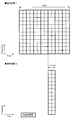
- the configuration is determined. For example, FIG.
- the transmission apparatus multiplexes transmission signals on the non-orthogonal axis and all the resources multiplexed on the non-orthogonal axis have the same parameter set.
- the transmission device indicates either the base station device 1 or the terminal device 2.
- a plurality of transmission signal sets to be multiplexed are prepared.
- FIG. 12 it is assumed that two transmission signal sets are multiplexed. Although the number is two here, three or more transmission signal sets may be used.
- each transmission signal set may be a transmission signal for different reception devices, or may be a transmission signal for the same reception device.
- the receiving device indicates either the base station device 1 or the terminal device 2.
- a corresponding Multiple Access (MA) signature is applied to each transmission signal set.
- MA Multiple Access
- MA signature includes, for example, Interleave pattern, Spreading Pattern, Scrambling Pattern, Codebook, Power Allocation, Repetition, and the like.
- MA signature may be simply referred to as Pattern or Index, and as an example, refers to an identifier such as Pattern or Index used in NOMA transmission as described above, or representing the Pattern itself.
- the signals after applying the MA signature are multiplexed on the same frequency and time resource and sent to the same antenna port.
- transmission signal sets having the same parameter set are multiplexed.
- transmission signal sets having different parameter sets may be multiplexed.
- FIG. 13 is the same as FIG. 12 except that transmission signal sets with different parameter sets are multiplexed.
- a method is also conceivable in which a signal to which the MA signature is applied is transmitted without being multiplexed by the transmission apparatus, and transmission is performed such that the reception apparatus performs non-orthogonal multiplexing.
- the corresponding MA signature is applied to each transmission signal set.
- MA signature includes, for example, Interleave pattern, Spreading Pattern, Scrambling Pattern, Codebook, Power Allocation, Repetition, and the like.
- the signal after applying the MA signature is transmitted on the same frequency and time resource and multiplexed through the propagation channel.
- each transmission signal set may be transmitted from a separate transmission device.
- the parameter sets of transmission signals transmitted on the same frequency and time resource may be different parameter sets.
- FIG. 16 is an example of a receiving device. As shown in FIG. 16, the received signal is received in a state where a plurality of transmission signals are multiplexed on the same frequency and time resource. In order to decode the multiplexed transmission signal set, the receiving apparatus applies the MA signature applied by the transmitter, and extracts a desired signal by channel equalization and an interference signal canceller. At this time, if multiplexing is performed using the same MA signature, the influence of interference between multiplexed signals becomes large, and decoding becomes difficult.
- the MA signature applied by the transmission device and the reception device must be shared between the transmission device and the reception device, and the MA signature must be applied without duplication.
- MA signature is included as one of the resources.
- a resource including all of the frequency, time, and MA signature may be referred to as a Multiple Access (MA) resource, and a resource including only the frequency and time may be referred to as a Multiple Access (MA) Physical resource.
- MA Multiple Access
- Grant-free transmission means that the terminal device 2 does not receive the resource allocation (Grant) from the base station device 1, and the terminal device 2 performs transmission using resources separated by an appropriate frequency axis and time axis. Represents what to do. That is, Grant-free transmission represents transmission of data without including Grant in Downlink Control Information.
- the base station apparatus 1 may specify in advance frequency and time resource candidates that the terminal apparatus 2 can select. Main purposes include power saving and low-latency communication of the terminal device 2 by reducing signaling overhead. Conventionally, the base station apparatus 1 has been able to communicate without causing resource contention with other terminal apparatuses 2 by notifying the terminal apparatus 2 of resources used in Uplink and Sidelink. However, signaling overhead due to this notification occurs.
- Step S11 when data is generated (Step S11), the terminal device 2 issues a resource allocation request to the base station device 1 (Step S12). In response to the resource allocation request, the base station device 1 allocates resources to the terminal device 2 (step S13). The terminal device 2 transmits Data using the resources allocated from the base station device 1 (step S14), and the base station device 1 returns a response (step 15). The signaling overhead.
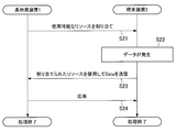
- FIG. 18 is a flowchart showing an example of Grant-free transmission.
- the base station apparatus 1 allocates usable resources to the terminal apparatus 2, and the base station apparatus 1 allocates resources to the terminal apparatus 2 in response to the resource allocation request (step S21).
- the terminal device 2 generates data (step S22)
- the terminal device 2 transmits Data using the resources allocated from the base station device 1 (step S23), and the base station device 1 returns a response (step S23).
- Step 24 grant-free transmission without resource allocation notification is considered as a promising technology candidate in power saving and low-delay communication required for next-generation communication.
- Transmission resources in grant-free transmission may be selected from all available bands, or may be selected from resources designated in advance by the base station apparatus 1.
- the terminal device 2 When the terminal device 2 performs NOMA transmission, the terminal device 2 transmits by applying the MA signature described above. While NOMA transmission can be expected to improve frequency utilization efficiency, MA signature application processing is required on the transmission side, and interference cancellation processing is required on the reception side. Furthermore, depending on the type of MA Signature, more time / frequency resources may be required than OMA transmission. For example, when using Spreading or Repetition as MA signature. NOMA transmission is very effective when transmission resources are insufficient for OMA transmission. On the other hand, if sufficient resources can be secured even by OMA transmission, OMA transmission may be better in consideration of the processing load of the transmitting terminal and the receiving terminal and the use efficiency of time / frequency resources. The above is the advantage of switching from NOMA transmission to OMA transmission.
- the terminal device 2 must use time / frequency resources different from those of other terminal devices when performing OMA transmission. Therefore, when the number of terminal devices that transmit data is large, time / frequency resources may be insufficient. If time / frequency resources are insufficient, the terminal apparatus 2 may transmit at the next transmission timing, but this causes a transmission delay. Therefore, although the terminal device 2 applies NOMA transmission, the processing load of interference cancellation increases, but on the other hand, in addition to time / frequency resources, non-orthogonal resources can be used, and transmission is possible. You can increase the number. The above is the advantage of switching from OMA transmission to NOMA transmission.
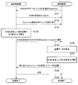
- FIG. 19 shows an example of a switching sequence between NOMA transmission and OMA transmission when the terminal device 2 performs Grant-based Uplink transmission.
- a series of processing is executed by the control unit 103 and the control unit 203, for example.
- the terminal device 2 notifies the base station device 1 whether or not NOMA transmission is supported (step S101). If the terminal device 2 supports NOMA transmission, the base station device 1 sets NOMA transmission to the terminal device 2 (step S102). Specifically, the base station apparatus 1 notifies the terminal apparatus 2 whether or not NOMA transmission can be performed, or whether or not NOMA transmission is always performed.
- step S103 When a permission notification indicating that NOMA transmission may be performed is transmitted from the base station apparatus 1 to the terminal apparatus 2, switching processing between NOMA transmission and OMA transmission is performed.
- the base station apparatus 1 detects a trigger for switching between NOMA transmission and OMA transmission (step S103). After detecting the trigger, the base station device 1 may immediately notify the terminal device 2 whether or not to perform NOMA transmission (step S104).
- step S105 When transmission data is generated in the terminal device 2 (step S105), the terminal device 2 makes a resource allocation request to the base station device 1.
- the base station device 1 allocates resources to the terminal device 2 (step S107).
- the base station apparatus 1 may send a notification of whether or not to perform NOMA transmission to the terminal apparatus 2 after the resource allocation request in step S106.
- the base station apparatus 1 may perform switching notification as to whether or not to perform NOMA transmission to the terminal apparatus 2 after resource allocation in step S107 (step S108).
- the terminal device 2 selects whether to transmit data to the base station device 1 by either NOMA transmission or OMA transmission in accordance with the notification from the base station device 1 (step S109), and uses the allocated resource to the base station Data is transmitted to the device 1 (step S110).
- the base station apparatus 1 transmits a response (ACK or NACK) to the data transmission in step S110 to the terminal apparatus 2 (step S111).
- FIG. 20 shows an example of a switching sequence between NOMA transmission and OMA transmission when the terminal device 2 performs Grant-free Uplink transmission.
- a series of processing is executed by the control unit 103 and the control unit 203, for example.
- the terminal device 2 notifies the base station device 1 whether or not NOMA transmission is supported (step S121). If the terminal device 2 supports NOMA transmission, the base station device 1 sets NOMA transmission to the terminal device 2 (step S122). Specifically, the base station apparatus 1 notifies the terminal apparatus 2 whether or not NOMA transmission can be performed, or whether or not NOMA transmission is always performed. When a permission notification indicating that NOMA transmission may be performed is transmitted from the base station apparatus 1 to the terminal apparatus 2, switching processing between NOMA transmission and OMA transmission is performed.
- the base station apparatus 1 allocates grant-free transmission resources to the terminal apparatus 2 in advance (step S123). For example, it is assumed that the base station apparatus 1 detects a trigger for switching between NOMA transmission and OMA transmission (step S124). After detecting the trigger, the base station device 1 notifies the terminal device 2 of whether or not to perform NOMA transmission (step S125). The notification of switching whether or not to perform NOMA transmission is notified based on information notified to Explicit or Implicit information associated with other information.
- step S126 When transmission data is generated in the terminal device 2 (step S126), according to the notification from the base station device 1, it is selected whether to transmit data to the base station device 1 by either NOMA transmission or OMA transmission (step S127). Data is transmitted to the base station apparatus 1 using resources allocated for grant-free transmission (step S128). The base station apparatus 1 transmits a response (ACK or NACK) to the data transmission in step S128 to the terminal apparatus 2 (step S129).
- ACK or NACK ACK
- step S124 An example of a switching trigger between NOMA transmission and OMA transmission in step S124 and an example of switching between NOMA transmission and OMA transmission based on Explicit information or Implicit information in step S125 will be described below.
- Number of users accommodated in cell For example, the number of users accommodated in a cell may be used as a trigger. When the number of users accommodated in a cell becomes a certain number or more, an increase in traffic of the entire cell can be considered. In this case, the base station apparatus 1 can be considered to increase the frequency use efficiency by switching from OMA transmission to NOMA transmission.
- the number of users accommodated in the beam may be used as a trigger. If the number of users accommodated in the same beam exceeds a certain level, an increase in traffic can be considered. In this case, the base station apparatus 1 can be considered to increase the frequency use efficiency by switching from OMA transmission to NOMA transmission.
- the transmission may be switched to OMA transmission. Since the base station apparatus 1 may not have correctly received the uplink transmission from the terminal apparatus 2 due to the interference of the other terminal apparatus 2, the base station apparatus 1 switches to the OMA transmission without the interference of the other terminal apparatus 2. Thus, the possibility of correct reception at the time of retransmission improves.
- System Information is information notified by broadcast or multicast. Therefore, all or a plurality of terminal devices 2 accommodated in the base station device 1 are switched between NOMA transmission and OMA transmission based on the information of System Information.
- the information notified by System Information may be an information bit representing NOMA transmission or OMA transmission.
- the base station apparatus 1 notifies broadcast or multicast including information bits indicating NOMA transmission or OMA transmission in predetermined System Information.
- the plurality of terminal devices 2 can switch between NOMA transmission or OMA transmission by receiving the notification from the base station device 1.
- the terminal device 2 cannot receive System Information correctly.
- the terminal device 2 may not perform NOMA transmission or may not perform OMA transmission, for example, when System Information cannot be received correctly. If the terminal device 2 has received System Information correctly, the terminal device 2 determines whether to perform NOMA transmission or OMA transmission based on the information of the System Information.
- the system information transmitted from the base station device 1 may not include information such as NOMA transmission or OMA transmission. If no information is included in the System Information, the terminal device 2 may not perform NOMA transmission or may not perform OMA transmission. When information is included in System Information, the terminal device 2 switches between NOMA transmission and OMA transmission according to the information.
- switching information is notified by RRC Signaling.
- the terminal device 2 is switched based on switching information between NOMA transmission and OMA transmission included in RRC signaling.
- the information notified by RRC Signaling may include information bits indicating NOMA transmission or OMA transmission, or information instructing switching from the current access method to the other access method.
- the instruction to switch to the other access method is, for example, that the current access method is NOMA transmission, and that switching to OMA transmission is performed when a switching instruction bit is received.
- the terminal device 2 cannot correctly receive the RRC signaling. If the terminal device 2 cannot receive the RRC signaling correctly, for example, if the information is notified by System Information, the terminal device 2 may follow the notified information. If neither System Information is notified or System Information is not received, the terminal device 2 may not perform NOMA transmission or OMA transmission. Furthermore, even if RRC Signaling is correctly received, there is a case where switching information is not included. In this case, the terminal device 2 may follow the notified information if the information is notified by, for example, System Information. If neither System Information is notified or System Information is not received, the terminal device 2 may not perform NOMA transmission or OMA transmission.
- UE-specific PDCCH is Explicitly Notification and Switching This embodiment is an example in which switching information is notified by a signal transmitted from the base station apparatus 1 by UE-Specific PDCCH.
- a signal transmitted by UE-specific PDCCH is a control signal that can be received only by a specific user.
- the base station apparatus 1 may transmit NCI transmission and DCI to the terminal apparatus 2 by adding information indicating NOMA transmission and OMA transmission to the DCI.
- the terminal device 2 switches between NOMA transmission and OMA transmission according to the information notified by the DCI.
- the base station apparatus 1 may add a bit string representing NOMA transmission or OMA transmission to the MCS table included in the DCI. Further, the base station apparatus 1 may prepare an NOMA MCS table or an OMA MCS table.
- the base station apparatus 1 may add a bit string representing NOMA transmission or OMA transmission to a bit string representing Resource Allocation, or may add a bit string representing MA Signature.
- the bit string representing the MA signature may be composed of a bit sequence representing the OMA and a bit sequence representing the MA signature sequence in NOMA transmission.
- the base station apparatus 1 may separate DCI Format for OMA transmission and NOMA transmission.
- the base station device 1 prepares a radio network temporary identifier (RNTI) for OMA and another RNTI for NOMA, and the terminal device 2 performs CRC check with each RNTI at the time of CRC check after DCI decoding. It may be determined whether to switch between NOMA transmission and OMA transmission.
- FIG. 21 and FIG. 22 show an embodiment of determination of OMA transmission and NOMA transmission by RNTI.
- FIG. 21 is a determination example of the transmission side (Transmitter, for example, the base station device 1)
- FIG. 22 is a determination example of the reception side (Receiver, for example, the terminal device 2).
- the base station apparatus 1 calculates the CRC from the DCI payload and scrambles the OMA RNTI when instructing the OMA transmission in the uplink.
- the base station apparatus 1 uses the OMA RNTI. Scramble. Then, the base station apparatus 1 attaches a scrambled CRC (Scrambled CRC) to the payload and transmits it to the terminal apparatus 2.
- the terminal device 2 After decoding the DCI, the terminal device 2 descrambles each of the OMA RNTI and the NOMA RNTI, and performs a CRC check. If the DCI can be correctly decoded, the CRC check will pass with one of the RNTI descrambles, so that the terminal device 2 can know whether to perform OMA transmission by uplink transmission or NOMA transmission. Become.
- FIG. 23 shows an example of the Group-common PDCCH.
- the Control Resource Set (CORESET) in FIG. 23 is an area where control information is transmitted. As part of this CORESET, Group-common PDCCH is transmitted.
- the base station apparatus 1 performs notification using Group-common DCI including switching information of NOMA transmission and OMA transmission of each single or plural users.
- the base station apparatus 1 performs notification using Group-common DCI including NOMA transmission common to all single or plural users and OMA transmission switching information.
- the Group-Common DCI may be transmitted together with other information, or may be a Group-Common DCI including only NOMA transmission and OMA transmission switching information.
- the base station apparatus 1 may be prepared separately for the OMA RNTI and the NOMA RNTI, and the terminal apparatus 2 uses the RNTI for the CRC check after decoding the Group-common DCI. It may be determined whether to switch between NOMA transmission and OMA transmission by performing a CRC check.
- the scrambled Group-common DCI may be a Group-common DCI that does not include switching information between NOMA transmission and OMA transmission, or may be a Group-common DCI that includes switching information between NOMA transmission and OMA transmission. Good.
- This example divides Search Space for NOMA and OMA so that terminal device 2 can perform NOMA transmission or OMA transmission.
- the terminal device 2 performs Blind Decoding of DCI in order to determine whether the DCI is addressed to itself.
- the DCI may be a UE-specific DCI or a group-common DCI transmitted to a plurality of terminal apparatuses.
- Blind Decoding if the CRC check passes normally, the terminal device 2 determines that the DCI is addressed to itself. At this time, the terminal device 2 can determine switching between NOMA transmission and OMA transmission depending on whether the received DCI belongs to the NOMA Search Space or the OMA Search Space.
- Common Search Space and UE-specific Search Space as Search Space, but it may be limited to either Search Space. For example, it may be limited to UE-specific Search Space, or may be limited to Common Search Space.
- the terminal device 2 when limited to UE-specific Search Space, performs Blind Decoding in each of the UE-specific Search Space for NOMA and the UE-specific Search Space for OMA.
- One CORESET includes one or more Search Spaces.
- one or more CORESETs are included in one band. For example, if there are two CORESETs # 0 and # 1, CORESET # 0 is NOMA transmission and CORESET # 1 is OMA transmission, so that the terminal device 2 can determine switching between NOMA transmission and OMA transmission. .
- FIG. 24 is an example in which two CORESETs are included in the band.
- FIG. 24 shows an example in which two CORESETs are multiplexed in the time direction, but they may be multiplexed in the frequency direction.
- Implicit notification and switching using the time / frequency resource notified by Grant This embodiment switches NOMA transmission and OMA transmission according to the time / frequency resource granted by the base station apparatus 1. It is an example. If the time / frequency resource granted by the base station apparatus 1 is a resource for NOMA transmission, the terminal apparatus 2 performs NOMA transmission, while if the granted time / frequency resource is a resource for OMA transmission, the terminal The device 2 performs OMA transmission.
- the correspondence between granted time / frequency resources and NOMA transmission or OMA transmission may be statically determined in advance as a specification, or may be quasi-statically notified from the base station apparatus 1 to the terminal apparatus 2.
- the terminal device 2 may perform NOMA transmission, and if not, the terminal device 2 may perform OMA transmission.
- the above example is an example, and the present embodiment can be applied as long as it is information on granted time / frequency resources.
- NOMA transmission or OMA transmission is associated with Grant-free transmission and Grant-based transmission, respectively. It is an Example which switches OMA transmission.
- grant-free transmission is associated with NOMA transmission
- grant-based transmission is associated with OMA transmission.
- terminal device 2 When transmitting without Grant, terminal device 2 performs NOMA transmission, and when receiving Grant, terminal device 2 performs OMA transmission. Judgment to send.
- the correspondence between Grant-free transmission or Grant-based transmission and NOMA transmission or OMA transmission may be statically determined in advance as a specification, or semi-statically notified from the base station apparatus 1 to the terminal apparatus 2 Also good. Further, the same transmission method may be assigned to both Grant-free transmission and Grant-based transmission. For example, when NOMA transmission is assigned to both Grant-free transmission and Grant-based transmission, the terminal device 2 performs NOMA transmission by both Grant-free transmission and Grant-based transmission.
- Grant-free transmission and Grant-based transmission may be limited to NOMA transmission or OMA transmission.
- the terminal device 2 may be restricted not to use NOMA transmission.
- limiting is not restricted to the said example.
- This embodiment is an embodiment in which NOMA transmission and OMA transmission are switched by linking NOMA transmission or OMA transmission to a transmittable Waveform.
- the terminal device 2 can transmit two of OFDM transmission and DFT-s-OFDM transmission.
- OFDM transmission is linked to NOMA transmission
- DFT-s-OFDM transmission is linked to OMA transmission
- NOF transmission is performed for OFDM transmission
- OMA transmission is performed for DFT-s-OFDM transmission.
- the terminal device 2 determines.
- the correspondence between Waveform that can be transmitted and NOMA transmission or OMA transmission may be statically determined in advance as a specification, or may be quasi-statically notified from the base station apparatus 1 to the terminal apparatus 2.
- the same transmission method may be assigned to a plurality or all of the transmittable Waveforms.
- NOMA transmission is assigned to both OFDM transmission and DFT-s-OFDM transmission
- the terminal device 2 performs NOMA transmission by both OFDM transmission and DFT-s-OFDM transmission.
- a specific Waveform may be restricted to NOMA transmission or OMA transmission.
- the terminal device 2 may be restricted not to use NOMA transmission.
- limiting is not restricted to the said example.
- This embodiment is an embodiment in which NOMA transmission and OMA transmission are switched by associating HARQ Process number with NOMA transmission or OMA transmission.
- the terminal device 2 transmits with two HARQ Process # 0 and HARQ Process # 1.
- HARQ Process # 0 is linked with NOMA transmission
- HARQ Process # 1 is linked with OMA transmission
- NOMA transmission is performed when HARQ Process # 0 is transmitted
- OMA transmission is transmitted when HARQ Process # 1 is transmitted.
- the terminal device 2 makes a determination.
- the correspondence between HARQ Process and NOMA transmission or OMA transmission may be statically determined in advance as a specification, or may be notified from the base station apparatus 1 to the terminal apparatus 2 semi-statically. Further, the same transmission method may be assigned to a plurality or all of the HARQ Processes. For example, when NOMA transmission is assigned to both HARQ Process # 0 and HARQ Process # 1, the terminal device 2 performs NOMA transmission using both HARQ Process # 0 and HARQ Process # 1.
- a specific HARQ process may be restricted to NOMA transmission or OMA transmission.
- the terminal device 2 may be restricted not to use NOMA transmission.
- limiting is not restricted to the said example.
- Implicit notification by DMRS sequence and switching This embodiment is configured to link NOMA transmission or OMA transmission to the DMRS sequence transmitted from the base station apparatus 1 to the terminal apparatus 2 by linking NOMA transmission or OMA transmission. It is an Example which switches transmission. For example, it is assumed that the terminal device 2 receives two DMRS Sequence # 0 and DMRS Sequence # 1. Here, DMRS Sequence # 0 is linked to NOMA transmission, DMRS Sequence # 1 is linked to OMA transmission, NDM transmission is performed when DMRS Sequence # 0 is received, and OMA transmission is performed when DMRS Sequence # 1 is received. Thus, the terminal device 2 makes a determination.
- DMRS Sequence and NOMA transmission or OMA transmission may be statically determined in advance as a specification, or may be semi-statically notified from the base station apparatus to the terminal apparatus. Further, the same transmission method may be assigned to a plurality or all of DMRS Sequences. For example, when NOMA transmission is assigned to both DMRS Sequence # 0 and DMRS Sequence # 1, the terminal device 2 performs NOMA transmission when receiving either DMRS Sequence # 0 or DMRS Sequence # 1. Become.
- This embodiment is an embodiment in which NOMA transmission and OMA transmission are switched by linking NOMA transmission or OMA transmission to Cell.
- the terminal device 2 transmits and receives with two Cell # 0 and Cell # 1.
- Cell # 0 is linked to NOMA transmission
- Cell # 1 is linked to OMA transmission
- NOMA transmission is performed when transmitting with Cell # 0
- OMA transmission is performed when transmitting with Cell # 1.
- the terminal device 2 determines.
- the correspondence between Cell and NOMA transmission or OMA transmission may be statically determined in advance as a specification, or may be notified from the base station apparatus 1 to the terminal apparatus 2 semi-statically. Further, the same transmission method may be assigned to a plurality or all of the cells. For example, when NOMA transmission is assigned to both Cell # 0 and Cell # 1, the terminal device 2 performs NOMA transmission when receiving either Cell # 0 or Cell # 1.
- this embodiment can also be applied to Carrier Aggregation and Dual connectivity.
- a specific cell may be restricted to NOMA transmission or OMA transmission.
- the terminal device 2 may be restricted not to use NOMA transmission.
- limiting is not restricted to the said example.
- This example is an example of switching NOMA transmission and OMA transmission by linking NOMA transmission or OMA transmission to Licensed Band or Unlicensed Band. is there.
- the terminal device 2 can transmit using a licensed band or an unlicensed band.
- the terminal device 2 is configured such that the Licensed Band is associated with NOMA transmission, the Unlicensed Band is associated with OMA transmission, NOMA transmission is performed when transmitting with the Licensed Band, and OMA transmission is performed when transmitting with the Unlicensed Band.
- the Licensed Band is associated with NOMA transmission
- the Unlicensed Band is associated with OMA transmission
- NOMA transmission is performed when transmitting with the Licensed Band
- OMA transmission is performed when transmitting with the Unlicensed Band.
- the correspondence between Licensed Band or Unlicensed Band and NOMA transmission or OMA transmission may be statically determined in advance as a specification, or may be semi-statically notified from the base station apparatus to the terminal apparatus. Further, the same transmission method may be assigned to both Licensed Band and Unlicensed Band. For example, when NOMA transmission is assigned to both the Licensed Band and Unlicensed Band, the terminal device 2 performs NOMA transmission regardless of whether transmission is performed using either the Licensed Band or the Unlicensed Band.
- either or both Licensed Band and Unlicensed Band may be restricted to NOMA transmission or OMA transmission.
- the terminal device 2 may be restricted not to use NOMA transmission.
- limiting is not restricted to the said example.
- Implicit notification and switching using channels such as PUCCH and PUSCH This example switches NOMA transmission and OMA transmission by associating a transmission channel such as PUCCH and PUSCH with NOMA transmission or OMA transmission. It is an example.
- the terminal device 2 performs uplink transmission using PUCCH or PUSCH.
- the terminal device 2 determines that PUSCH is linked to NOMA transmission and PUCCH is linked to OMA transmission, so that NOMA transmission is performed when transmitting via PUSCH, and OMA transmission is performed when transmitting via PUCCH.
- the correspondence between channels such as PUCCH and PUSCH and NOMA transmission or OMA transmission may be statically determined in advance as a specification, or may be quasi-statically notified from the base station apparatus to the terminal apparatus. Further, the same transmission method may be assigned to a plurality or all of the channels. For example, when NOMA transmission is assigned to both PUCCH and PUSCH, the terminal device 2 performs NOMA transmission regardless of whether PUCCH or PUSCH is used for transmission.
- a specific channel may be limited to NOMA transmission or OMA transmission.
- the terminal device 2 may be restricted not to use NOMA transmission.
- limiting is not restricted to the said example.
- NOMA transmission may be performed depending on the transmission format among specific channels. For example, assuming that PUCCH is basically OMA transmission, the terminal device 2 may use NOMA transmission only when sending a Scheduling Request using PUCCH. Regardless of Scheduling Request, other information such as ACK / NACK and CSI may be restricted.
- This example is an example in which NOMA transmission and OMA transmission are switched by linking Slot and Mini-slot with NOMA transmission or OMA transmission. is there.
- the terminal device 2 can transmit with a slot and a mini-slot.
- the terminal device 2 is such that Mini-slot is linked with NOMA transmission, Slot is linked with OMA transmission, NOMA transmission is performed when transmitting with Mini-slot, and OMA transmission is performed when transmitting with Slot.
- the correspondence between Slot and Mini-slot and NOMA transmission or OMA transmission may be statically determined in advance as a specification, or may be quasi-statically notified from the base station apparatus 1 to the terminal apparatus 2. Further, the same transmission method may be assigned to both Slot and Mini-Slot. For example, when NOMA transmission is assigned to both Slot and Mini-slot, the terminal device 2 performs NOMA transmission regardless of whether transmission is performed using either Slot or Mini-slot.
- FIG. 25 shows an embodiment in which both Slot and Mini-slot are NOMA.
- FIG. 25 is an example in which NOMA is applied to both Slot and Mini-slot. NOMA is applied to each of the slot and mini-slot areas. Further, it is assumed that the frequency regions of the terminal device-1 and the terminal device-2 are the same.
- the terminal device-1 transmits using a slot, and the terminal device-2 transmits using a mini-slot. At this time, by setting the NOMA application range of the terminal device-1 to be the same as the NOMA application range of the terminal device-2, even if the two terminal devices transmit at the same time and frequency, the base station device 1 can be decoded by an interference canceller.
- either Slot or Mini-slot or both may be limited to NOMA transmission or OMA transmission.
- the terminal device 2 may be restricted not to use NOMA transmission.
- limiting is not restricted to the said example.
- Subcarrier Spacing notifies Implicit to switch
- This embodiment switches NOMA transmission and OMA transmission by associating Subcarrier Spacing with NOMA transmission or OMA transmission.
- the terminal device 2 can transmit at a subcarrier spacing of 15 kHz and 30 kHz.
- Subcarrier Spacing 30kHz is linked to NOMA transmission
- 15kHz is linked to OMA transmission
- NOMA transmission is performed when transmitting at 30kHz
- OMA transmission is performed when transmitting at 15kHz.
- the correspondence between Subcarrier Spacing and NOMA transmission or OMA transmission may be statically determined in advance as a specification, or may be notified from the base station apparatus 1 to the terminal apparatus 2 semi-statically.
- the same transmission method may be assigned to a plurality or all of Subcarrier Spacing. For example, when NOMA transmission is assigned to both 15 kHz and 30 kHz, the terminal device 2 performs NOMA transmission when transmitting at either 15 kHz or 30 kHz.
- specific subcarrier spacing may be limited to NOMA transmission or OMA transmission.
- the terminal device 2 may be restricted not to use NOMA transmission.
- a relatively wide Subcarrier Spacing such as 240 kHz is considered to be used in a relatively high frequency band such as a millimeter wave band, for example. This is because, in a relatively high frequency band, it is considered that a relatively large number of frequency resources can be used, so that there is a possibility that sufficient resources can be secured without performing NOMA transmission.
- NOMA transmission may be applied in a high frequency band, or NOMA transmission may be applied even in a relatively wide subcarrier spacing such as 240 kHz.
- limiting is not restricted to the said example.
- NOMA transmission and OMA transmission are switched by associating the parameter set with NOMA transmission or OMA transmission.
- the terminal device 2 can transmit with parameter sets # 0 and # 1.
- parameter set # 0 is linked to NOMA transmission
- parameter set # 1 is linked to OMA transmission
- NOMA transmission is performed when parameter set # 0 is transmitted
- OMA transmission is transmitted when parameter set # 1 is transmitted.
- the terminal device 2 makes a determination.
- the correspondence between the parameter set and NOMA transmission or OMA transmission may be statically determined in advance as a specification, or may be notified from the base station apparatus 1 to the terminal apparatus 2 semi-statically.
- the same transmission method may be assigned to a plurality or all of the parameter sets. For example, when NOMA transmission is assigned to both parameter set # 0 and parameter set # 1, terminal device 2 performs NOMA transmission regardless of whether parameter set # 0 or parameter set # 1 is used for transmission. become.
- a specific parameter set may be limited to NOMA transmission or OMA transmission.
- the terminal device 2 may be restricted not to use NOMA transmission.
- limiting is not restricted to the said example.
- NOMA transmission and OMA are linked by linking 2-step RACH Procedure or 4-step RACH Procedure and NOMA transmission or OMA transmission. It is an Example which switches transmission.
- the 4-step RACH Procedure is an initial access procedure used in LTE.
- 4-step RACH terminal device 2 at 1 st step of Procedure sends the Preamble to the base station apparatus 1, the base station apparatus 1 in 2 nd step and the response to the reception of the Preamble, the Grant for 3 rd step terminal Transmit to device 2.
- 3, rd Step, 2 using the Grant resources by nd step performs transmission of data terminal equipment 2 is required for the initial set in the base station apparatus 1, the base station apparatus 1 in 4 th step the terminal apparatus 2 Respond to.
- 2-step RACH Procedure is a RACH Procedure omitting the 1 st step and 2 nd step of the 4-step RACH Procedure.
- 1 st step of the 2-step RACH Procedure and transmitted to the base station apparatus 1 together data terminal device is required to Preamble and initialization, the base station apparatus 1 in 2 nd step is a response to the terminal apparatus 2 .
- the 2-step RACH Procedure is that in one st step, a plurality of terminal devices 2 may transmit data using the same time / frequency resource, and the base station device 1 may not be able to decode the data. .
- NOMA transmission is applied in 1 st step so that a plurality of terminal devices 2 can perform decoding even when using the same time / frequency resource.
- 4-step RACH Procedure to implement data transmission in 3 rd step in OMA transmission.
- NOMA transmission is linked in the case of 2-step RACH Procedure
- OMA transmission is linked in the case of 4-step RACH Procedure.
- OMA transmission may be applied by 2-step RACH Procedure, or NOMA transmission may be applied by 4-step RACH Procedure.
- the terminal device 2 performs a handover to another cell.
- the terminal device 2 receives a broadcast signal such as System Information transmitted from the handover destination base station device 1 and confirms whether it is compatible with NOMA transmission. If the terminal device 2 supports NOMA transmission, the terminal device 2 notifies the base station device 1 of Capability for NOMA transmission, and the base station device 1 notifies the terminal device 2 whether or not NOMA transmission is allowed. On the other hand, if the handover destination base station apparatus 1 does not support NOMA, the terminal apparatus 2 switches from NOMA transmission to OMA transmission and performs OMA transmission.
- a broadcast signal such as System Information transmitted from the handover destination base station device 1 and confirms whether it is compatible with NOMA transmission. If the terminal device 2 supports NOMA transmission, the terminal device 2 notifies the base station device 1 of Capability for NOMA transmission, and the base station device 1 notifies the terminal device 2 whether or not NOMA transmission is allowed. On the other hand, if the handover destination base station apparatus 1 does not support NOMA, the terminal apparatus 2 switches from NOMA
- the terminal device 2 can switch between NOMA transmission and OMA transmission based on various information.
- the uplink is mainly shown.
- the above embodiment is not limited to the uplink only, and it is also applied to the communication with a side link such as Device to Device or a relay terminal. Is possible.
- the base station device 1 may be realized as any type of eNB (evolved Node B) such as a macro eNB or a small eNB.
- the small eNB may be an eNB that covers a cell smaller than a macro cell, such as a pico eNB, a micro eNB, or a home (femto) eNB.
- the base station apparatus 1 may be realized as another type of base station such as Node B or BTS (Base Transceiver Station).
- the base station apparatus 1 may include a main body (also referred to as a base station apparatus) that controls wireless communication and one or more RRHs (Remote Radio Heads) that are arranged at locations different from the main body. Further, various types of terminals to be described later may operate as the base station device 1 by temporarily or semi-permanently executing the base station function.
- a main body also referred to as a base station apparatus
- RRHs Remote Radio Heads
- the terminal device 2 is a smartphone, a tablet PC (Personal Computer), a notebook PC, a portable game terminal, a mobile terminal such as a portable / dongle type mobile router or a digital camera, or an in-vehicle terminal such as a car navigation device. It may be realized as.
- the terminal device 2 may be realized as a terminal (also referred to as an MTC (Machine Type Communication) terminal) that performs M2M (Machine To Machine) communication.
- the terminal device 2 may be a wireless communication module (for example, an integrated circuit module configured by one die) mounted on these terminals.
- FIG. 26 is a block diagram illustrating a first example of a schematic configuration of an eNB to which the technology according to the present disclosure may be applied.
- the eNB 800 includes one or more antennas 810 and a base station device 820. Each antenna 810 and the base station apparatus 820 can be connected to each other via an RF cable.
- Each of the antennas 810 has a single or a plurality of antenna elements (for example, a plurality of antenna elements constituting a MIMO antenna), and is used for transmission and reception of radio signals by the base station apparatus 820.
- the eNB 800 includes a plurality of antennas 810 as illustrated in FIG. 26, and the plurality of antennas 810 may respectively correspond to a plurality of frequency bands used by the eNB 800, for example. 26 shows an example in which the eNB 800 includes a plurality of antennas 810, but the eNB 800 may include a single antenna 810.
- the base station apparatus 820 includes a controller 821, a memory 822, a network interface 823, and a wireless communication interface 825.
- the controller 821 may be a CPU or a DSP, for example, and operates various functions of the upper layer of the base station apparatus 820. For example, the controller 821 generates a data packet from the data in the signal processed by the wireless communication interface 825, and transfers the generated packet via the network interface 823. The controller 821 may generate a bundled packet by bundling data from a plurality of baseband processors, and may transfer the generated bundled packet. In addition, the controller 821 is a logic that executes control such as radio resource control, radio bearer control, mobility management, inflow control, or scheduling. May have a typical function. Moreover, the said control may be performed in cooperation with a surrounding eNB or a core network node.
- the memory 822 includes RAM and ROM, and stores programs executed by the controller 821 and various control data (for example, terminal list, transmission power data, scheduling data, and the like).
- the network interface 823 is a communication interface for connecting the base station device 820 to the core network 824.
- the controller 821 may communicate with the core network node or other eNB via the network interface 823.
- the eNB 800 and the core network node or another eNB may be connected to each other by a logical interface (for example, an S1 interface or an X2 interface).
- the network interface 823 may be a wired communication interface or a wireless communication interface for wireless backhaul.
- the network interface 823 may use a frequency band higher than the frequency band used by the wireless communication interface 825 for wireless communication.
- the wireless communication interface 825 supports any cellular communication scheme such as LTE (Long Term Evolution) or LTE-Advanced, and provides a wireless connection to terminals located in the cell of the eNB 800 via the antenna 810.
- the wireless communication interface 825 may typically include a baseband (BB) processor 826, an RF circuit 827, and the like.
- the BB processor 826 may perform, for example, encoding / decoding, modulation / demodulation, and multiplexing / demultiplexing, and each layer (for example, L1, MAC (Medium Access Control), RLC (Radio Link Control), and PDCP).
- Various signal processing of Packet Data Convergence Protocol
- Packet Data Convergence Protocol is executed.
- the BB processor 826 may have some or all of the logical functions described above instead of the controller 821.
- the BB processor 826 may be a module that includes a memory that stores a communication control program, a processor that executes the program, and related circuits. The function of the BB processor 826 may be changed by updating the program. Good.
- the module may be a card or a blade inserted into a slot of the base station apparatus 820, or a chip mounted on the card or the blade.
- the RF circuit 827 may include a mixer, a filter, an amplifier, and the like, and transmits and receives a radio signal via the antenna 810.
- the radio communication interface 825 includes a plurality of BB processors 826 as illustrated in FIG. 26, and the plurality of BB processors 826 may respectively correspond to a plurality of frequency bands used by the eNB 800, for example.
- the wireless communication interface 825 may include a plurality of RF circuits 827 as illustrated in FIG. 26, and the plurality of RF circuits 827 may correspond to, for example, a plurality of antenna elements.
- 26 shows an example in which the wireless communication interface 825 includes a plurality of BB processors 826 and a plurality of RF circuits 827, the wireless communication interface 825 includes a single BB processor 826 or a single RF circuit 827. But you can.
- the eNB 800 includes a module including a part (for example, the BB processor 826) or all of the wireless communication interface 825 and / or the controller 821, and the one or more components are mounted in the module. Good.
- the module stores a program for causing the processor to function as the one or more components (in other words, a program for causing the processor to execute the operation of the one or more components). The program may be executed.
- a program for causing a processor to function as the one or more components is installed in the eNB 800, and the radio communication interface 825 (eg, the BB processor 826) and / or the controller 821 executes the program.
- the eNB 800, the base station apparatus 820, or the module may be provided as an apparatus including the one or more components, and a program for causing a processor to function as the one or more components is provided. May be.
- a readable recording medium in which the program is recorded may be provided.
- the reception unit 105 and the transmission unit 107 described with reference to FIG. 8 may be implemented in the wireless communication interface 825 (for example, the RF circuit 827).
- the transmission / reception antenna 109 may be mounted on the antenna 810.
- an interface between the upper layer processing unit 101 and an upper node or another base station apparatus may be implemented in the controller 821 and / or the network interface 823.
- FIG. 27 is a block diagram illustrating a second example of a schematic configuration of an eNB to which the technology according to the present disclosure may be applied.
- the eNB 830 includes one or more antennas 840, a base station apparatus 850, and an RRH 860. Each antenna 840 and RRH 860 may be connected to each other via an RF cable. Base station apparatus 850 and RRH 860 can be connected to each other via a high-speed line such as an optical fiber cable.
- Each of the antennas 840 has a single or a plurality of antenna elements (for example, a plurality of antenna elements constituting a MIMO antenna), and is used for transmission / reception of radio signals by the RRH 860.
- the eNB 830 includes a plurality of antennas 840 as illustrated in FIG. 27, and the plurality of antennas 840 may respectively correspond to a plurality of frequency bands used by the eNB 830, for example.
- 27 illustrates an example in which the eNB 830 includes a plurality of antennas 840, but the eNB 830 may include a single antenna 840.
- the base station device 850 includes a controller 851, a memory 852, a network interface 853, a wireless communication interface 855, and a connection interface 857.
- the controller 851, the memory 852, and the network interface 853 are the same as the controller 821, the memory 822, and the network interface 823 described with reference to FIG.
- the wireless communication interface 855 supports a cellular communication method such as LTE or LTE-Advanced, and provides a wireless connection to a terminal located in a sector corresponding to the RRH 860 via the RRH 860 and the antenna 840.
- the wireless communication interface 855 may typically include a BB processor 856 and the like.
- the BB processor 856 is the same as the BB processor 826 described with reference to FIG. 26 except that the BB processor 856 is connected to the RF circuit 864 of the RRH 860 via the connection interface 857.
- the wireless communication interface 855 includes a plurality of BB processors 856 as illustrated in FIG.
- the plurality of BB processors 856 may respectively correspond to a plurality of frequency bands used by the eNB 830, for example.
- 27 shows an example in which the wireless communication interface 855 includes a plurality of BB processors 856, the wireless communication interface 855 may include a single BB processor 856.
- connection interface 857 is an interface for connecting the base station device 850 (wireless communication interface 855) to the RRH 860.
- the connection interface 857 may be a communication module for communication on the high-speed line that connects the base station apparatus 850 (wireless communication interface 855) and the RRH 860.
- the RRH 860 includes a connection interface 861 and a wireless communication interface 863.
- connection interface 861 is an interface for connecting the RRH 860 (wireless communication interface 863) to the base station device 850.
- the connection interface 861 may be a communication module for communication on the high-speed line.
- the wireless communication interface 863 transmits and receives wireless signals via the antenna 840.
- the wireless communication interface 863 may typically include an RF circuit 864 and the like.
- the RF circuit 864 may include a mixer, a filter, an amplifier, and the like, and transmits and receives wireless signals via the antenna 840.
- the wireless communication interface 863 includes a plurality of RF circuits 864 as illustrated in FIG. 27, and the plurality of RF circuits 864 may correspond to, for example, a plurality of antenna elements, respectively.
- 27 illustrates an example in which the wireless communication interface 863 includes a plurality of RF circuits 864, the wireless communication interface 863 may include a single RF circuit 864.
- the eNB 830 illustrated in FIG. 27 one or more components (upper layer processing unit 101 and / or control unit 103) included in the base station device 1 described with reference to FIG.
- the wireless communication interface 863 may be implemented.
- at least some of these components may be implemented in the controller 851.
- the eNB 830 includes a module including a part (for example, the BB processor 856) or the whole of the wireless communication interface 855 and / or the controller 851, and the one or more components are mounted in the module. Good.
- the module stores a program for causing the processor to function as the one or more components (in other words, a program for causing the processor to execute the operation of the one or more components).
- the program may be executed.
- a program for causing a processor to function as the one or more components is installed in the eNB 830, and the wireless communication interface 855 (eg, the BB processor 856) and / or the controller 851 executes the program.
- the eNB 830, the base station apparatus 850, or the module may be provided as an apparatus including the one or more components, and a program for causing a processor to function as the one or more components is provided. May be.
- a readable recording medium in which the program is recorded may be provided.
- the reception unit 105 and the transmission unit 107 described with reference to FIG. 8 may be implemented in the wireless communication interface 863 (for example, the RF circuit 864). Further, the transmission / reception antenna 109 may be mounted in the antenna 840. Further, the interface between the upper layer processing unit 101 and the upper node or another base station apparatus may be implemented in the controller 851 and / or the network interface 853.
- FIG. 28 is a block diagram illustrating an example of a schematic configuration of a smartphone 900 to which the technology according to the present disclosure can be applied.
- the smartphone 900 includes a processor 901, a memory 902, a storage 903, an external connection interface 904, a camera 906, a sensor 907, a microphone 908, an input device 909, a display device 910, a speaker 911, a wireless communication interface 912, one or more antenna switches 915.
- One or more antennas 916, a bus 917, a battery 918 and an auxiliary controller 919 are provided.
- the processor 901 may be, for example, a CPU or a SoC (System on Chip), and controls the functions of the application layer and other layers of the smartphone 900.
- the memory 902 includes a RAM and a ROM, and stores programs executed by the processor 901 and data.
- the storage 903 can include a storage medium such as a semiconductor memory or a hard disk.
- the external connection interface 904 is an interface for connecting an external device such as a memory card or a USB (Universal Serial Bus) device to the smartphone 900.
- the camera 906 includes, for example, an image sensor such as a CCD (Charge Coupled Device) or a CMOS (Complementary Metal Oxide Semiconductor), and generates a captured image.
- the sensor 907 may include a sensor group such as a positioning sensor, a gyro sensor, a geomagnetic sensor, and an acceleration sensor.
- the microphone 908 converts sound input to the smartphone 900 into an audio signal.
- the input device 909 includes, for example, a touch sensor that detects a touch on the screen of the display device 910, a keypad, a keyboard, a button, or a switch, and receives an operation or information input from a user.
- the display device 910 has a screen such as a liquid crystal display (LCD) or an organic light emitting diode (OLED) display, and displays an output image of the smartphone 900.
- the speaker 911 converts an audio signal output from the smartphone 900 into audio.
- the wireless communication interface 912 supports any cellular communication method such as LTE or LTE-Advanced, and performs wireless communication.
- the wireless communication interface 912 may typically include a BB processor 913, an RF circuit 914, and the like.
- the BB processor 913 may perform, for example, encoding / decoding, modulation / demodulation, and multiplexing / demultiplexing, and performs various signal processing for wireless communication.
- the RF circuit 914 may include a mixer, a filter, an amplifier, and the like, and transmits and receives radio signals via the antenna 916.
- the wireless communication interface 912 may be a one-chip module in which the BB processor 913 and the RF circuit 914 are integrated.
- the wireless communication interface 912 may include a plurality of BB processors 913 and a plurality of RF circuits 914 as illustrated in FIG.
- FIG. 28 shows an example in which the wireless communication interface 912 includes a plurality of BB processors 913 and a plurality of RF circuits 914.
- the wireless communication interface 912 includes a single BB processor 913 or a single RF circuit 914. But you can.
- the wireless communication interface 912 may support other types of wireless communication methods such as a short-range wireless communication method, a proximity wireless communication method, or a wireless LAN (Local Area Network) method in addition to the cellular communication method.
- a BB processor 913 and an RF circuit 914 for each wireless communication method may be included.
- Each of the antenna switches 915 switches the connection destination of the antenna 916 among a plurality of circuits (for example, circuits for different wireless communication systems) included in the wireless communication interface 912.
- Each of the antennas 916 includes a single or a plurality of antenna elements (for example, a plurality of antenna elements constituting a MIMO antenna), and is used for transmission / reception of a radio signal by the radio communication interface 912.
- the smartphone 900 may include a plurality of antennas 916 as illustrated in FIG. Note that FIG. 28 illustrates an example in which the smartphone 900 includes a plurality of antennas 916, but the smartphone 900 may include a single antenna 916.
- the smartphone 900 may include an antenna 916 for each wireless communication method.
- the antenna switch 915 may be omitted from the configuration of the smartphone 900.
- the bus 917 connects the processor 901, the memory 902, the storage 903, the external connection interface 904, the camera 906, the sensor 907, the microphone 908, the input device 909, the display device 910, the speaker 911, the wireless communication interface 912, and the auxiliary controller 919 to each other.
- the battery 918 supplies electric power to each block of the smartphone 900 shown in FIG. 28 through a power supply line partially shown by a broken line in the drawing.
- the auxiliary controller 919 operates the minimum necessary functions of the smartphone 900 in the sleep mode.
- the smartphone 900 shown in FIG. 28 one or more components (upper layer processing unit 201 and / or control unit 203) included in the terminal device 2 described with reference to FIG. 9 are implemented in the wireless communication interface 912. May be. Alternatively, at least some of these components may be implemented in the processor 901 or the auxiliary controller 919. As an example, the smartphone 900 includes a module including a part (for example, the BB processor 913) or the whole of the wireless communication interface 912, the processor 901, and / or the auxiliary controller 919, and the one or more components in the module. May be implemented.
- the module stores a program for causing the processor to function as the one or more components (in other words, a program for causing the processor to execute the operation of the one or more components).
- the program may be executed.
- a program for causing a processor to function as the one or more components is installed in the smartphone 900, and the wireless communication interface 912 (eg, the BB processor 913), the processor 901, and / or the auxiliary controller 919 is The program may be executed.
- the smartphone 900 or the module may be provided as a device including the one or more components, and a program for causing a processor to function as the one or more components may be provided.
- a readable recording medium in which the program is recorded may be provided.
- the reception unit 205 and the transmission unit 207 described with reference to FIG. 9 may be implemented in the wireless communication interface 912 (for example, the RF circuit 914).
- the transmission / reception antenna 209 may be mounted on the antenna 916.
- FIG. 29 is a block diagram illustrating an example of a schematic configuration of a car navigation device 920 to which the technology according to the present disclosure can be applied.
- the car navigation device 920 includes a processor 921, a memory 922, a GPS (Global Positioning System) module 924, a sensor 925, a data interface 926, a content player 927, a storage medium interface 928, an input device 929, a display device 930, a speaker 931, and wireless communication.
- the interface 933 includes one or more antenna switches 936, one or more antennas 937, and a battery 938.
- the processor 921 may be a CPU or SoC, for example, and controls the navigation function and other functions of the car navigation device 920.
- the memory 922 includes RAM and ROM, and stores programs and data executed by the processor 921.
- the GPS module 924 measures the position (for example, latitude, longitude, and altitude) of the car navigation device 920 using GPS signals received from GPS satellites.
- the sensor 925 may include a sensor group such as a gyro sensor, a geomagnetic sensor, and an atmospheric pressure sensor.
- the data interface 926 is connected to the in-vehicle network 941 through a terminal (not shown), for example, and acquires data generated on the vehicle side such as vehicle speed data.
- the content player 927 reproduces content stored in a storage medium (for example, CD or DVD) inserted into the storage medium interface 928.
- the input device 929 includes, for example, a touch sensor, a button, or a switch that detects a touch on the screen of the display device 930, and receives an operation or information input from the user.
- the display device 930 has a screen such as an LCD or an OLED display, and displays a navigation function or an image of content to be reproduced.
- the speaker 931 outputs the navigation function or the audio of the content to be played back.
- the wireless communication interface 933 supports any cellular communication method such as LTE or LTE-Advanced, and performs wireless communication.
- the wireless communication interface 933 may typically include a BB processor 934, an RF circuit 935, and the like.
- the BB processor 934 may perform, for example, encoding / decoding, modulation / demodulation, and multiplexing / demultiplexing, and performs various signal processing for wireless communication.
- the RF circuit 935 may include a mixer, a filter, an amplifier, and the like, and transmits and receives a radio signal via the antenna 937.
- the wireless communication interface 933 may be a one-chip module in which the BB processor 934 and the RF circuit 935 are integrated.
- the wireless communication interface 933 may include a plurality of BB processors 934 and a plurality of RF circuits 935 as shown in FIG. 29 shows an example in which the wireless communication interface 933 includes a plurality of BB processors 934 and a plurality of RF circuits 935, the wireless communication interface 933 includes a single BB processor 934 or a single RF circuit 935. But you can.
- the wireless communication interface 933 may support other types of wireless communication methods such as a short-range wireless communication method, a proximity wireless communication method, or a wireless LAN method in addition to the cellular communication method.
- a BB processor 934 and an RF circuit 935 may be included for each communication method.
- Each of the antenna switches 936 switches the connection destination of the antenna 937 among a plurality of circuits included in the wireless communication interface 933 (for example, circuits for different wireless communication systems).
- Each of the antennas 937 has a single or a plurality of antenna elements (for example, a plurality of antenna elements constituting a MIMO antenna), and is used for transmission / reception of a radio signal by the radio communication interface 933.
- the car navigation device 920 may include a plurality of antennas 937 as shown in FIG. Note that FIG. 29 illustrates an example in which the car navigation apparatus 920 includes a plurality of antennas 937, but the car navigation apparatus 920 may include a single antenna 937.
- the car navigation device 920 may include an antenna 937 for each wireless communication method.
- the antenna switch 936 may be omitted from the configuration of the car navigation device 920.
- the battery 938 supplies power to each block of the car navigation apparatus 920 shown in FIG. 29 via a power supply line partially shown by a broken line in the drawing. Further, the battery 938 stores electric power supplied from the vehicle side.
- the car navigation apparatus 920 includes a module including a part (for example, the BB processor 934) or the whole of the wireless communication interface 933 and / or the processor 921, and the one or more components are mounted in the module. May be.
- the module stores a program for causing the processor to function as the one or more components (in other words, a program for causing the processor to execute the operation of the one or more components). The program may be executed.
- a program for causing a processor to function as the one or more components is installed in the car navigation device 920, and the wireless communication interface 933 (eg, the BB processor 934) and / or the processor 921 executes the program.
- the car navigation apparatus 920 or the module may be provided as an apparatus including the one or more components, and a program for causing a processor to function as the one or more components may be provided. Good.
- a readable recording medium in which the program is recorded may be provided.
- the reception unit 205 and the transmission unit 207 described with reference to FIG. 9 may be implemented in the wireless communication interface 933 (for example, the RF circuit 935). Further, the transmission / reception antenna 209 may be mounted on the antenna 937.
- the technology according to the present disclosure may be realized as an in-vehicle system (or vehicle) 940 including one or more blocks of the car navigation device 920 described above, an in-vehicle network 941, and a vehicle side module 942.
- vehicle-side module 942 generates vehicle-side data such as vehicle speed, engine speed, or failure information, and outputs the generated data to the in-vehicle network 941.
- eNB gNodeB, next Generation NodeB.
- the base station apparatus 1 that notifies information for switching between OMA transmission and NOMA transmission and the base station apparatus 1 is notified of OMA transmission and NOMA transmission.
- the terminal device 2 to be switched based on the information is provided.
- each step in the processing executed by each device in this specification does not necessarily have to be processed in chronological order in the order described as a sequence diagram or flowchart.
- each step in the processing executed by each device may be processed in an order different from the order described as the flowchart, or may be processed in parallel.
- a communication device comprising: (2) The control unit is one of the orthogonal multiple access communication and the non-orthogonal multiple access communication based on the control information that the acquisition unit acquires and explicitly specifies either the orthogonal multiple access communication or the non-orthogonal multiple access communication.
- the communication device according to (1) wherein the communication device is selected.
- the communication apparatus wherein the control information is notified by RRC signaling.
- the communication apparatus wherein the control information is notified through a physical downlink control channel.
- the control information is based on the decryption result using the ID information for orthogonal multiple access communication and the ID information for non-orthogonal multiple access communication with respect to the encrypted information.
- the communication device wherein either one is selected.
- the control unit is one of the orthogonal multiple access communication and the non-orthogonal multiple access communication acquired based on the non-control information acquired by the acquisition unit and not explicitly specifying either the orthogonal multiple access communication or the non-orthogonal multiple access communication.
- the communication device according to (1), wherein the communication device is selected.
- the communication device wherein the control unit selects either orthogonal multiple access communication or non-orthogonal multiple access communication depending on a location of a search space where downlink control information exists.
- the control unit selects either orthogonal multiple access communication or non-orthogonal multiple access communication depending on a location of a resource allocated from the device.
- the control unit selects either orthogonal multiple access communication or non-orthogonal multiple access communication according to a communication method for transmitting with grant from the device and a communication method for transmitting without grant.
- control unit selects either orthogonal multiple access communication or non-orthogonal multiple access communication depending on a type of slot used for transmission to the device.
- control unit selects either orthogonal multiple access communication or non-orthogonal multiple access communication depending on a type of channel used for transmission from the device.
- control unit selects either orthogonal multiple access communication or non-orthogonal multiple access communication depending on a procedure type of a random access channel used for transmission with the device.
- control unit controls wireless communication with the device using a communication method in which resources are not allocated in advance.
- the information acquired by the acquisition unit is information transmitted when the number of terminals accommodated in the cell of the device exceeds a predetermined number, according to any one of (1) to (14) Communication device.
- the information acquired by the acquisition unit is information transmitted when the number of terminals accommodated in a beam emitted by the device exceeds a predetermined number, according to any one of (1) to (14).
- Communication equipment 17.
- the information acquired by the acquisition unit is information for switching from non-orthogonal multiple access communication to orthogonal multiple access communication, which is transmitted when the device cannot receive data by non-orthogonal multiple access communication. 1) The communication device according to any one of (14).
- the communication device according to any one of (1) to (17), wherein the information acquired by the acquisition unit is information indicating whether non-orthogonal multiple access communication is supported. (19) Obtaining information from a device performing wireless communication; Based on the acquired information, selecting either orthogonal multiple access communication or non-orthogonal multiple access communication for communication with the device; A communication method comprising executing a processor. (20) On the computer, Obtaining information from a device performing wireless communication; Based on the acquired information, selecting either orthogonal multiple access communication or non-orthogonal multiple access communication for communication with the device; A computer program that executes
Landscapes
- Engineering & Computer Science (AREA)
- Signal Processing (AREA)
- Computer Networks & Wireless Communication (AREA)
- Mobile Radio Communication Systems (AREA)
Abstract
【課題】基地局装置と端末装置が通信する通信システムにおいて、様々なユースケースに応じて柔軟に設計することにより、システム全体の伝送効率を大幅に向上させることができる通信装置を提供する。 【解決手段】無線通信を行っている装置から情報を取得する取得部と、前記取得部が取得した情報に基づいて、前記装置との通信に直交多元接続通信と非直交多元接続通信のいずれかを選択する制御部と、を備える、通信装置が提供される。
Description
本開示は、通信装置、通信方法及びコンピュータプログラムに関する。
セルラー移動通信の無線アクセス方式および無線ネットワーク(以下、「Long Term Evolution(LTE)」、「LTE-Advanced(LTE-A)」、「LTE-Advanced Pro(LTE-A Pro)」、「New Radio(NR)」、「New Radio Access Technology(NRAT)」、「Evolved Universal Terrestrial Radio Access(EUTRA)」、または「Further EUTRA(FEUTRA)」とも称する。)が、第三世代パートナーシッププロジェクト(3rd Generation Partnership Project:3GPP)において検討されている。なお、以下の説明において、LTEは、LTE-A、LTE-A Pro、およびEUTRAを含み、NRは、NRAT、およびFEUTRAを含む。LTEおよびNRでは、基地局装置(基地局)はeNodeB(evolved NodeB)、端末装置(移動局、移動局装置、端末)はUE(User Equipment)とも称する。LTEおよびNRは、基地局装置がカバーするエリアをセル状に複数配置するセルラー通信システムである。単一の基地局装置は複数のセルを管理してもよい。
NRは、LTEに対する次世代の無線アクセス方式として、LTEとは異なるRAT(Radio Access Technology)である。NRは、eMBB(Enhanced mobile broadband)、mMTC(Massive machine type communications)およびURLLC(Ultra reliable and low latency communications)を含む様々なユースケースに対応できるアクセス技術である。NRは、それらのユースケースにおける利用シナリオ、要求条件、および配置シナリオなどに対応する技術フレームワークを目指して検討される。NRでは、LTEと比較して約20倍の最大データレート対応や約10倍の端末数同時通信対応などといった理由から、さらなる周波数利用効率の向上が求められている。周波数利用効率を向上する技術の一つとして非直交多元接続(Non-orthogonal Multiple Access : NOMA)技術が注目されている。NOMAの技術詳細は、非特許文献1に開示されている。
Yuya Saito, Yoshihisa Kishiyama, Anass Benjebbour, Takehiro Nakamura, Anxin Li, and Kenichi Higuchi, "Non-Orthogonal Multiple Access (NOMA) for Future Radio Access," Vehicular Technology Conference (VTC Spring), 2013 IEEE 77th, pp. 1-5, Jun. 2013.
NRでは、さまざまなユースケースに対応するため、LTEよりも高い周波数利用効率の通信を行うことが求められている。
そこで本開示は、上記問題を鑑みてなされたものであり、その目的は、基地局装置と端末装置が通信する通信システムにおいて、様々なユースケースに応じて柔軟に設計することにより、システム全体の伝送効率を大幅に向上させることができる、新規かつ改良された通信装置、通信方法及びコンピュータプログラムを提供することにある。
本開示によれば、無線通信を行っている装置から情報を取得する取得部と、前記取得部が取得した情報に基づいて、前記装置との通信に直交多元接続通信と非直交多元接続通信のいずれかを選択する制御部と、を備える、通信装置が提供される。
また本開示によれば、無線通信を行っている装置から情報を取得することと、取得した前記情報に基づいて、前記装置との通信に直交多元接続通信と非直交多元接続通信のいずれかを選択することと、をプロセッサが実行することを含む、通信方法が提供される。
また本開示によれば、コンピュータに、無線通信を行っている装置から情報を取得することと、取得した前記情報に基づいて、前記装置との通信に直交多元接続通信と非直交多元接続通信のいずれかを選択することと、を実行させる、コンピュータプログラムが提供される。
以上説明したように本開示によれば、基地局装置と端末装置が通信する通信システムにおいて、様々なユースケースに応じて柔軟に設計することにより、システム全体の伝送効率を大幅に向上させることができる、新規かつ改良された通信装置、通信方法及びコンピュータプログラムを提供することができる。
なお、上記の効果は必ずしも限定的なものではなく、上記の効果とともに、または上記の効果に代えて、本明細書に示されたいずれかの効果、または本明細書から把握され得る他の効果が奏されてもよい。
以下に添付図面を参照しながら、本開示の好適な実施の形態について詳細に説明する。なお、本明細書及び図面において、実質的に同一の機能構成を有する構成要素については、同一の符号を付することにより重複説明を省略する。
なお、説明は以下の順序で行うものとする。
1.本開示の実施の形態
2.応用例
3.まとめ
1.本開示の実施の形態
2.応用例
3.まとめ
また、特に明記されない限り、以下で説明される技術、機能、方法、構成、手順、およびその他全ての記載は、LTEおよびNRに適用できる。
<1.本開示の実施の形態>
<本実施形態における無線通信システム>
本実施形態において、無線通信システムは、基地局装置1および端末装置2を少なくとも具備する。基地局装置1は複数の端末装置を収容できる。基地局装置1は、他の基地局装置とX2インターフェースの手段によって互いに接続できる。また、基地局装置1は、S1インターフェースの手段によってEPC(Evolved Packet Core)に接続できる。さらに、基地局装置1は、S1-MMEインターフェースの手段によってMME(Mobility Management Entity)に接続でき、S1-Uインターフェースの手段によってS-GW(Serving Gateway)に接続できる。S1インターフェースは、MMEおよび/またはS-GWと基地局装置1との間で、多対多の接続をサポートしている。また、本実施形態において、基地局装置1および端末装置2は、それぞれLTEおよび/またはNRをサポートする。
<本実施形態における無線通信システム>
本実施形態において、無線通信システムは、基地局装置1および端末装置2を少なくとも具備する。基地局装置1は複数の端末装置を収容できる。基地局装置1は、他の基地局装置とX2インターフェースの手段によって互いに接続できる。また、基地局装置1は、S1インターフェースの手段によってEPC(Evolved Packet Core)に接続できる。さらに、基地局装置1は、S1-MMEインターフェースの手段によってMME(Mobility Management Entity)に接続でき、S1-Uインターフェースの手段によってS-GW(Serving Gateway)に接続できる。S1インターフェースは、MMEおよび/またはS-GWと基地局装置1との間で、多対多の接続をサポートしている。また、本実施形態において、基地局装置1および端末装置2は、それぞれLTEおよび/またはNRをサポートする。
<本実施形態における無線アクセス技術>
本実施形態において、基地局装置1および端末装置2は、それぞれ1つ以上の無線アクセス技術(RAT)をサポートする。例えば、RATは、LTEおよびNRを含む。1つのRATは、1つのセル(コンポーネントキャリア)に対応する。すなわち、複数のRATがサポートされる場合、それらのRATは、それぞれ異なるセルに対応する。本実施形態において、セルは、下りリンクリソース、上りリンクリソース、および/または、サイドリンクの組み合わせである。また、以下の説明において、LTEに対応するセルはLTEセルと呼称され、NRに対応するセルはNRセルと呼称される。
本実施形態において、基地局装置1および端末装置2は、それぞれ1つ以上の無線アクセス技術(RAT)をサポートする。例えば、RATは、LTEおよびNRを含む。1つのRATは、1つのセル(コンポーネントキャリア)に対応する。すなわち、複数のRATがサポートされる場合、それらのRATは、それぞれ異なるセルに対応する。本実施形態において、セルは、下りリンクリソース、上りリンクリソース、および/または、サイドリンクの組み合わせである。また、以下の説明において、LTEに対応するセルはLTEセルと呼称され、NRに対応するセルはNRセルと呼称される。
下りリンクの通信は、基地局装置1から端末装置2に対する通信である。上りリンクの通信は、端末装置2から基地局装置1に対する通信である。サイドリンクの通信は、端末装置2から別の端末装置2に対する通信である。
サイドリンクの通信は、端末装置間の近接直接検出および近接直接通信のために定義される。サイドリンクの通信は、上りリンクおよび下りリンクと同様なフレーム構成を用いることができる。また、サイドリンクの通信は、上りリンクリソースおよび/または下りリンクリソースの一部(サブセット)に制限されうる。
基地局装置1および端末装置2は、下りリンク、上りリンクおよび/またはサイドリンクにおいて、1つ以上のセルの集合を用いる通信をサポートできる。複数のセルの集合は、キャリアアグリゲーションまたはデュアルコネクティビティとも呼称される。キャリアアグリゲーションとデュアルコネクティビティの詳細は後述される。また、それぞれのセルは、所定の周波数帯域幅を用いる。所定の周波数帯域幅における最大値、最小値および設定可能な値は、予め規定できる。
図1は、本実施形態におけるコンポーネントキャリアの設定の一例を示す図である。図1の例では、1つのLTEセルと2つのNRセルが設定される。1つのLTEセルは、プライマリーセルとして設定される。2つのNRセルは、それぞれプライマリーセカンダリーセルおよびセカンダリーセルとして設定される。2つのNRセルは、キャリアアグリゲーションにより統合される。また、LTEセルとNRセルは、デュアルコネクティビティにより統合される。なお、LTEセルとNRセルは、キャリアアグリゲーションにより統合されてもよい。図1の例では、NRは、プライマリーセルであるLTEセルにより接続をアシストされることが可能であるため、スタンドアロンで通信するための機能のような一部の機能をサポートしなくてもよい。スタンドアロンで通信するための機能は、初期接続に必要な機能を含む。
図2は、本実施形態におけるコンポーネントキャリアの設定の一例を示す図である。図2の例では、2つのNRセルが設定される。2つのNRセルは、それぞれプライマリーセルおよびセカンダリーセルとして設定され、キャリアアグリゲーションにより統合される。この場合、NRセルがスタンドアロンで通信するための機能をサポートすることにより、LTEセルのアシストが不要になる。なお、2つのNRセルは、デュアルコネクティビティにより統合されてもよい。
<本実施形態における無線フレーム構成>
本実施形態において、10ms(ミリ秒)で構成される無線フレーム(radio frame)が規定される。無線フレームのそれぞれは2つのハーフフレームから構成される。ハーフフレームの時間間隔は、5msである。ハーフフレームのそれぞれは、5つのサブフレームから構成される。サブフレームの時間間隔は、1msであり、2つの連続するスロットによって定義される。スロットの時間間隔は、0.5msである。無線フレーム内のi番目のサブフレームは、(2×i)番目のスロットと(2×i+1)番目のスロットとから構成される。つまり、無線フレームのそれぞれにおいて、10個のサブフレームが規定される。
本実施形態において、10ms(ミリ秒)で構成される無線フレーム(radio frame)が規定される。無線フレームのそれぞれは2つのハーフフレームから構成される。ハーフフレームの時間間隔は、5msである。ハーフフレームのそれぞれは、5つのサブフレームから構成される。サブフレームの時間間隔は、1msであり、2つの連続するスロットによって定義される。スロットの時間間隔は、0.5msである。無線フレーム内のi番目のサブフレームは、(2×i)番目のスロットと(2×i+1)番目のスロットとから構成される。つまり、無線フレームのそれぞれにおいて、10個のサブフレームが規定される。
サブフレームは、下りリンクサブフレーム、上りリンクサブフレーム、スペシャルサブフレームおよびサイドリンクサブフレームなどを含む。
下りリンクサブフレームは下りリンク送信のために予約されるサブフレームである。上りリンクサブフレームは上りリンク送信のために予約されるサブフレームである。スペシャルサブフレームは3つのフィールドから構成される。3つのフィールドは、DwPTS(Downlink Pilot Time Slot)、GP(Guard Period)、およびUpPTS(Uplink Pilot Time Slot)を含む。DwPTS、GP、およびUpPTSの合計の長さは1msである。DwPTSは下りリンク送信のために予約されるフィールドである。UpPTSは上りリンク送信のために予約されるフィールドである。GPは下りリンク送信および上りリンク送信が行われないフィールドである。なお、スペシャルサブフレームは、DwPTSおよびGPのみによって構成されてもよいし、GPおよびUpPTSのみによって構成されてもよい。スペシャルサブフレームは、TDDにおいて下りリンクサブフレームと上りリンクサブフレームとの間に配置され、下りリンクサブフレームから上りリンクサブフレームに切り替えるために用いられる。サイドリンクサブフレームは、サイドリンク通信のために予約または設定されるサブフレームである。サイドリンクは、端末装置間の近接直接通信および近接直接検出のために用いられる。
単一の無線フレームは、下りリンクサブフレーム、上りリンクサブフレーム、スペシャルサブフレームおよび/またはサイドリンクサブフレームから構成される。また、単一の無線フレームは、下りリンクサブフレーム、上りリンクサブフレーム、スペシャルサブフレームまたはサイドリンクサブフレームのみで構成されてもよい。
複数の無線フレーム構成がサポートされる。無線フレーム構成は、フレーム構成タイプで規定される。フレーム構成タイプ1は、FDDのみに適用できる。フレーム構成タイプ2は、TDDのみに適用できる。フレーム構成タイプ3は、LAA(Licensed Assisted Access)セカンダリーセルの運用のみに適用できる。
フレーム構成タイプ2において、複数の上りリンク-下りリンク構成が規定される。上りリンク-下りリンク構成において、1つの無線フレームにおける10のサブフレームのそれぞれは、下りリンクサブフレーム、上りリンクサブフレーム、およびスペシャルサブフレームのいずれかに対応する。サブフレーム0、サブフレーム5およびDwPTSは常に下りリンク送信のために予約される。UpPTSおよびそのスペシャルサブフレームの直後のサブフレームは常に上りリンク送信のために予約される。
フレーム構成タイプ3において、1つの無線フレーム内の10のサブフレームが下りリンク送信のために予約される。端末装置2は、PDSCHまたは検出信号が送信されないサブフレームを空のサブフレームとして扱うことができる。端末装置2は、所定の信号、チャネルおよび/または下りリンク送信があるサブフレームで検出されない限り、そのサブフレームにいかなる信号および/またはチャネルも存在しないと想定する。下りリンク送信は、1つまたは複数の連続したサブフレームで専有される。その下りリンク送信の最初のサブフレームは、そのサブフレーム内のどこからでも開始されてもよい。その下りリンク送信の最後のサブフレームは、完全に専有されるか、DwPTSで規定される時間間隔で専有されるか、のいずれかであってもよい。
なお、フレーム構成タイプ3において、1つの無線フレーム内の10のサブフレームが上りリンク送信のために予約されてもよい。また、1つの無線フレーム内の10のサブフレームのそれぞれが、下りリンクサブフレーム、上りリンクサブフレーム、スペシャルサブフレームおよびサイドリンクサブフレームのいずれかに対応するようにしてもよい。
基地局装置1は、スペシャルサブフレームのDwPTSにおいて、物理下りリンクチャネルおよび物理下りリンク信号を送信してもよい。基地局装置1は、スペシャルサブフレームのDwPTSにおいて、PBCHの送信を制限できる。端末装置2は、スペシャルサブフレームのUpPTSにおいて、物理上りリンクチャネルおよび物理上りリンク信号を送信してもよい。端末装置2は、スペシャルサブフレームのUpPTSにおいて、一部の物理上りリンクチャネルおよび物理上りリンク信号の送信を制限できる。
<本実施形態におけるNRのフレーム構成>
NRセルのそれぞれにおいて、ある所定の時間長(例えば、サブフレーム)では、1つ以上の所定のパラメータが用いられる。すなわち、NRセルでは、下りリンク信号および上りリンク信号は、それぞれ所定の時間長において、1つ以上の所定のパラメータを用いて生成される。換言すると、端末装置2は、基地局装置1から送信される下りリンク信号、および、基地局装置1に送信する上りリンク信号が、それぞれ所定の時間長において、1つ以上の所定のパラメータで生成される、と想定する。また、基地局装置1は、端末装置2に送信する下りリンク信号、および、端末装置2から送信される上りリンク信号が、それぞれ所定の時間長において、1つ以上の所定のパラメータで生成されるように設定できる。複数の所定のパラメータが用いられる場合、それらの所定のパラメータが用いられて生成される信号は、所定の方法により多重される。例えば、所定の方法は、FDM(Frequency Division Multiplexing)、TDM(Time Division Multiplexing)、CDM(Code Division Multiplexing)および/またはSDM(Spatial Division Multiplexing)などを含む。
NRセルのそれぞれにおいて、ある所定の時間長(例えば、サブフレーム)では、1つ以上の所定のパラメータが用いられる。すなわち、NRセルでは、下りリンク信号および上りリンク信号は、それぞれ所定の時間長において、1つ以上の所定のパラメータを用いて生成される。換言すると、端末装置2は、基地局装置1から送信される下りリンク信号、および、基地局装置1に送信する上りリンク信号が、それぞれ所定の時間長において、1つ以上の所定のパラメータで生成される、と想定する。また、基地局装置1は、端末装置2に送信する下りリンク信号、および、端末装置2から送信される上りリンク信号が、それぞれ所定の時間長において、1つ以上の所定のパラメータで生成されるように設定できる。複数の所定のパラメータが用いられる場合、それらの所定のパラメータが用いられて生成される信号は、所定の方法により多重される。例えば、所定の方法は、FDM(Frequency Division Multiplexing)、TDM(Time Division Multiplexing)、CDM(Code Division Multiplexing)および/またはSDM(Spatial Division Multiplexing)などを含む。
NRセルに設定される所定のパラメータの組み合わせは、パラメータセットとして、複数種類を予め規定できる。
図3は、NRセルにおける送信信号に関するパラメータセットの一例を示す図である。図3の例では、パラメータセットに含まれる送信信号に関するパラメータは、サブフレーム間隔、NRセルにおけるリソースブロックあたりのサブキャリア数、サブフレームあたりのシンボル数、および、CP長タイプである。CP長タイプは、NRセルで用いられるCP長のタイプである。例えば、CP長タイプ1はLTEにおけるノーマルCPに相当し、CP長タイプ2はLTEにおける拡張CPに相当する。
NRセルにおける送信信号に関するパラメータセットは、下りリンクおよび上りリンクでそれぞれ個別に規定することができる。また、NRセルにおける送信信号に関するパラメータセットは、下りリンクおよび上りリンクでそれぞれ独立に設定できる。
図4は、本実施形態におけるNRの下りリンクサブフレームの一例を示す図である。図4の例では、パラメータセット1、パラメータセット0およびパラメータセット2を用いて生成される信号が、セル(システム帯域幅)において、FDMされる。図4に示される図は、NRの下りリンクリソースグリッドとも呼称される。基地局装置1は、端末装置2への下りリンクサブフレームにおいて、NRの物理下りリンクチャネルおよび/またはNRの物理下りリンク信号を送信できる。端末装置2は、基地局装置1からの下りリンクサブフレームにおいて、NRの物理下りリンクチャネルおよび/またはNRの物理下りリンク信号を受信できる。
図5は、本実施形態におけるNRの上りリンクサブフレームの一例を示す図である。図5の例では、パラメータセット1、パラメータセット0およびパラメータセット2を用いて生成される信号が、セル(システム帯域幅)において、FDMされる。図5に示される図は、NRの上りリンクリソースグリッドとも呼称される。基地局装置1は、端末装置2への上りリンクサブフレームにおいて、NRの物理上りリンクチャネルおよび/またはNRの物理上りリンク信号を送信できる。端末装置2は、基地局装置1からの上りリンクサブフレームにおいて、NRの物理上りリンクチャネルおよび/またはNRの物理上りリンク信号を受信できる。
<本実施形態における基地局装置1の構成例>
図6は、本実施形態の基地局装置1の構成を示す概略ブロック図である。図示するように、基地局装置1は、上位層処理部101、制御部103、受信部105、送信部107、および、送受信アンテナ109、を含んで構成される。また、受信部105は、復号化部1051、復調部1053、多重分離部1055、無線受信部1057、およびチャネル測定部1059を含んで構成される。また、送信部107は、符号化部1071、変調部1073、多重部1075、無線送信部1077、および下りリンク参照信号生成部1079を含んで構成される。
図6は、本実施形態の基地局装置1の構成を示す概略ブロック図である。図示するように、基地局装置1は、上位層処理部101、制御部103、受信部105、送信部107、および、送受信アンテナ109、を含んで構成される。また、受信部105は、復号化部1051、復調部1053、多重分離部1055、無線受信部1057、およびチャネル測定部1059を含んで構成される。また、送信部107は、符号化部1071、変調部1073、多重部1075、無線送信部1077、および下りリンク参照信号生成部1079を含んで構成される。
既に説明したように、基地局装置1は、1つ以上のRATをサポートできる。図6に示す基地局装置1に含まれる各部の一部または全部は、RATに応じて個別に構成されうる。例えば、受信部105および送信部107は、LTEとNRとで個別に構成される。また、NRセルにおいて、図6に示す基地局装置1に含まれる各部の一部または全部は、送信信号に関するパラメータセットに応じて個別に構成されうる。例えば、あるNRセルにおいて、無線受信部1057および無線送信部1077は、送信信号に関するパラメータセットに応じて個別に構成されうる。
上位層処理部101は、媒体アクセス制御(MAC: Medium Access Control)層、パケットデータ統合プロトコル(Packet Data Convergence Protocol: PDCP)層、無線リンク制御(Radio Link Control: RLC)層、無線リソース制御(Radio Resource Control: RRC)層の処理を行う。また、上位層処理部101は、受信部105、および送信部107の制御を行うために制御情報を生成し、制御部103に出力する。
制御部103は、上位層処理部101からの制御情報に基づいて、受信部105および送信部107の制御を行う。制御部103は、上位層処理部101への制御情報を生成し、上位層処理部101に出力する。制御部103は、復号化部1051からの復号化された信号およびチャネル測定部1059からのチャネル推定結果を入力する。制御部103は、符号化する信号を符号化部1071へ出力する。また、制御部103は、基地局装置1の全体または一部を制御するために用いられる。
上位層処理部101は、RAT制御、無線リソース制御、サブフレーム設定、スケジューリング制御、および/または、CSI報告制御に関する処理および管理を行う。上位層処理部101における処理および管理は、端末装置毎、または基地局装置に接続している端末装置共通に行われる。上位層処理部101における処理および管理は、上位層処理部101のみで行われてもよいし、上位ノードまたは他の基地局装置から取得してもよい。また、上位層処理部101における処理および管理は、RATに応じて個別に行われてもよい。例えば、上位層処理部101は、LTEにおける処理および管理と、NRにおける処理および管理とを個別に行う。
上位層処理部101におけるRAT制御では、RATに関する管理が行われる。例えば、RAT制御では、LTEに関する管理および/またはNRに関する管理が行われる。NRに関する管理は、NRセルにおける送信信号に関するパラメータセットの設定および処理を含む。
上位層処理部101における無線リソース制御では、下りリンクデータ(トランスポートブロック)、システムインフォメーション、RRCメッセージ(RRCパラメータ)、および/または、MAC制御エレメント(CE:Control Element)の生成および/または管理が行われる。
上位層処理部101におけるサブフレーム設定では、サブフレーム設定、サブフレームパターン設定、上りリンク-下りリンク設定、上りリンク参照UL-DL設定、および/または、下りリンク参照UL-DL設定の管理が行われる。なお、上位層処理部101におけるサブフレーム設定は、基地局サブフレーム設定とも呼称される。また、上位層処理部101におけるサブフレーム設定は、上りリンクのトラフィック量および下りリンクのトラフィック量に基づいて決定できる。また、上位層処理部101におけるサブフレーム設定は、上位層処理部101におけるスケジューリング制御のスケジューリング結果に基づいて決定できる。
上位層処理部101におけるスケジューリング制御では、受信したチャネル状態情報およびチャネル測定部1059から入力された伝搬路の推定値やチャネルの品質などに基づいて、物理チャネルを割り当てる周波数およびサブフレーム、物理チャネルの符号化率および変調方式および送信電力などが決定される。例えば、制御部103は、上位層処理部101におけるスケジューリング制御のスケジューリング結果に基づいて、制御情報(DCIフォーマット)を生成する。
上位層処理部101におけるCSI報告制御では、端末装置2のCSI報告が制御される。例えば、端末装置2においてCSIを算出するために想定するためのCSI参照リソースに関する設定が制御される。
受信部105は、制御部103からの制御に従って、送受信アンテナ109を介して端末装置2から送信された信号を受信し、さらに分離、復調、復号などの受信処理を行い、受信処理された情報を制御部103に出力する。なお、受信部105における受信処理は、あらかじめ規定された設定、または基地局装置1が端末装置2に通知した設定に基づいて行われる。
無線受信部1057は、送受信アンテナ109を介して受信された上りリンクの信号に対して、中間周波数への変換(ダウンコンバート)、不要な周波数成分の除去、信号レベルが適切に維持されるように増幅レベルの制御、受信された信号の同相成分および直交成分に基づく直交復調、アナログ信号からディジタル信号への変換、ガードインターバル(Guard Interval: GI)の除去、および/または、高速フーリエ変換(Fast Fourier Transform: FFT)による周波数領域信号の抽出を行う。
多重分離部1055は、無線受信部1057から入力された信号から、PUCCHまたはPUSCHなどの上りリンクチャネルおよび/または上りリンク参照信号を分離する。多重分離部1055は、上りリンク参照信号をチャネル測定部1059に出力する。多重分離部1055は、チャネル測定部1059から入力された伝搬路の推定値から、上りリンクチャネルに対する伝搬路の補償を行う。
復調部1053は、上りリンクチャネルの変調シンボルに対して、BPSK(Binary Phase Shift Keying)、QPSK(Quadrature Phase shift Keying)、16QAM(Quadrature Amplitude Modulation)、64QAM、256QAM等の変調方式を用いて受信信号の復調を行う。復調部1053は、MIMO多重された上りリンクチャネルの分離および復調を行う。
復号化部1051は、復調された上りリンクチャネルの符号化ビットに対して、復号処理を行う。復号された上りリンクデータおよび/または上りリンク制御情報は制御部103へ出力される。復号化部1051は、PUSCHに対しては、トランスポートブロック毎に復号処理を行う。
チャネル測定部1059は、多重分離部1055から入力された上りリンク参照信号から伝搬路の推定値および/またはチャネルの品質などを測定し、多重分離部1055および/または制御部103に出力する。例えば、UL-DMRSはPUCCHまたはPUSCHに対する伝搬路補償を行うための伝搬路の推定値を測定し、SRSは上りリンクにおけるチャネルの品質を測定する。
送信部107は、制御部103からの制御に従って、上位層処理部101から入力された下りリンク制御情報および下りリンクデータに対して、符号化、変調および多重などの送信処理を行う。例えば、送信部107は、PHICH、PDCCH、EPDCCH、PDSCH、および下りリンク参照信号を生成および多重し、送信信号を生成する。なお、送信部107における送信処理は、あらかじめ規定された設定、基地局装置1が端末装置2に通知した設定、または、同一のサブフレームで送信されるPDCCHまたはEPDCCHを通じて通知される設定に基づいて行われる。
符号化部1071は、制御部103から入力されたHARQインディケータ(HARQ-ACK)、下りリンク制御情報、および下りリンクデータを、ブロック符号化、畳込み符号化、ターボ符号化等の所定の符号化方式を用いて符号化を行う。変調部1073は、符号化部1071から入力された符号化ビットをBPSK、QPSK、16QAM、64QAM、256QAM等の所定の変調方式で変調する。下りリンク参照信号生成部1079は、物理セル識別子(PCI:Physical cell identification)、端末装置2に設定されたRRCパラメータなどに基づいて、下りリンク参照信号を生成する。多重部1075は、各チャネルの変調シンボルと下りリンク参照信号を多重し、所定のリソースエレメントに配置する。
無線送信部1077は、多重部1075からの信号に対して、逆高速フーリエ変換(Inverse Fast Fourier Transform: IFFT)による時間領域の信号への変換、ガードインターバルの付加、ベースバンドのディジタル信号の生成、アナログ信号への変換、直交変調、中間周波数の信号から高周波数の信号への変換(アップコンバート: up convert)、余分な周波数成分の除去、電力の増幅などの処理を行い、送信信号を生成する。無線送信部1077が出力した送信信号は、送受信アンテナ109から送信される。
<本実施形態における端末装置2の構成例>
図7は、本実施形態の端末装置2の構成を示す概略ブロック図である。図示するように、端末装置2は、上位層処理部201、制御部203、受信部205、送信部207、および送受信アンテナ209を含んで構成される。また、受信部205は、復号化部2051、復調部2053、多重分離部2055、無線受信部2057、およびチャネル測定部2059を含んで構成される。また、送信部207は、符号化部2071、変調部2073、多重部2075、無線送信部2077、および上りリンク参照信号生成部2079を含んで構成される。
図7は、本実施形態の端末装置2の構成を示す概略ブロック図である。図示するように、端末装置2は、上位層処理部201、制御部203、受信部205、送信部207、および送受信アンテナ209を含んで構成される。また、受信部205は、復号化部2051、復調部2053、多重分離部2055、無線受信部2057、およびチャネル測定部2059を含んで構成される。また、送信部207は、符号化部2071、変調部2073、多重部2075、無線送信部2077、および上りリンク参照信号生成部2079を含んで構成される。
既に説明したように、端末装置2は、1つ以上のRATをサポートできる。図7に示す端末装置2に含まれる各部の一部または全部は、RATに応じて個別に構成されうる。例えば、受信部205および送信部207は、LTEとNRとで個別に構成される。また、NRセルにおいて、図7に示す端末装置2に含まれる各部の一部または全部は、送信信号に関するパラメータセットに応じて個別に構成されうる。例えば、あるNRセルにおいて、無線受信部2057および無線送信部2077は、送信信号に関するパラメータセットに応じて個別に構成されうる。
上位層処理部201は、上りリンクデータ(トランスポートブロック)を、制御部203に出力する。上位層処理部201は、媒体アクセス制御(MAC: Medium Access Control)層、パケットデータ統合プロトコル(Packet Data Convergence Protocol: PDCP)層、無線リンク制御(Radio Link Control: RLC)層、無線リソース制御(Radio Resource Control: RRC)層の処理を行なう。また、上位層処理部201は、受信部205、および送信部207の制御を行うために制御情報を生成し、制御部203に出力する。
制御部203は、上位層処理部201からの制御情報に基づいて、受信部205および送信部207の制御を行う。制御部203は、上位層処理部201への制御情報を生成し、上位層処理部201に出力する。制御部203は、復号化部2051からの復号化された信号およびチャネル測定部2059からのチャネル推定結果を入力する。制御部203は、符号化する信号を符号化部2071へ出力する。また、制御部203は、端末装置2の全体または一部を制御するために用いられてもよい。
上位層処理部201は、RAT制御、無線リソース制御、サブフレーム設定、スケジューリング制御、および/または、CSI報告制御に関する処理および管理を行う。上位層処理部201における処理および管理は、あらかじめ規定される設定、および/または、基地局装置1から設定または通知される制御情報に基づく設定に基づいて行われる。例えば、基地局装置1からの制御情報は、RRCパラメータ、MAC制御エレメントまたはDCIを含む。また、上位層処理部201における処理および管理は、RATに応じて個別に行われてもよい。例えば、上位層処理部201は、LTEにおける処理および管理と、NRにおける処理および管理とを個別に行う。
上位層処理部201におけるRAT制御では、RATに関する管理が行われる。例えば、RAT制御では、LTEに関する管理および/またはNRに関する管理が行われる。NRに関する管理は、NRセルにおける送信信号に関するパラメータセットの設定および処理を含む。
上位層処理部201における無線リソース制御では、自装置における設定情報の管理が行われる。上位層処理部201における無線リソース制御では、上りリンクデータ(トランスポートブロック)、システムインフォメーション、RRCメッセージ(RRCパラメータ)、および/または、MAC制御エレメント(CE:Control Element)の生成および/または管理が行われる。
上位層処理部201におけるサブフレーム設定では、基地局装置1および/または基地局装置1とは異なる基地局装置におけるサブフレーム設定が管理される。サブフレーム設定は、サブフレームに対する上りリンクまたは下りリンクの設定、サブフレームパターン設定、上りリンク-下りリンク設定、上りリンク参照UL-DL設定、および/または、下りリンク参照UL-DL設定を含む。なお、上位層処理部201におけるサブフレーム設定は、端末サブフレーム設定とも呼称される。
上位層処理部201におけるスケジューリング制御では、基地局装置1からのDCI(スケジューリング情報)に基づいて、受信部205および送信部207に対するスケジューリングに関する制御を行うための制御情報が生成される。
上位層処理部201におけるCSI報告制御では、基地局装置1に対するCSIの報告に関する制御が行われる。例えば、CSI報告制御では、チャネル測定部2059でCSIを算出するために想定するためのCSI参照リソースに関する設定が制御される。CSI報告制御では、DCIおよび/またはRRCパラメータに基づいて、CSIを報告するために用いられるリソース(タイミング)を制御する。
受信部205は、制御部203からの制御に従って、送受信アンテナ209を介して基地局装置1から送信された信号を受信し、さらに分離、復調、復号などの受信処理を行い、受信処理された情報を制御部203に出力する。なお、受信部205における受信処理は、あらかじめ規定された設定、または基地局装置1からの通知または設定に基づいて行われる。
無線受信部2057は、送受信アンテナ209を介して受信された上りリンクの信号に対して、中間周波数への変換(ダウンコンバート)、不要な周波数成分の除去、信号レベルが適切に維持されるように増幅レベルの制御、受信された信号の同相成分および直交成分に基づく直交復調、アナログ信号からディジタル信号への変換、ガードインターバル(Guard Interval: GI)の除去、および/または、高速フーリエ変換(Fast Fourier Transform: FFT)による周波数領域の信号の抽出を行う。
多重分離部2055は、無線受信部2057から入力された信号から、PHICH、PDCCH、EPDCCHまたはPDSCHなどの下りリンクチャネル、下りリンク同期信号および/または下りリンク参照信号を分離する。多重分離部2055は、下りリンク参照信号をチャネル測定部2059に出力する。多重分離部2055は、チャネル測定部2059から入力された伝搬路の推定値から、下りリンクチャネルに対する伝搬路の補償を行う。
復調部2053は、下りリンクチャネルの変調シンボルに対して、BPSK、QPSK、16QAM、64QAM、256QAM等の変調方式を用いて受信信号の復調を行う。復調部2053は、MIMO多重された下りリンクチャネルの分離および復調を行う。
復号化部2051は、復調された下りリンクチャネルの符号化ビットに対して、復号処理を行う。復号された下りリンクデータおよび/または下りリンク制御情報は制御部203へ出力される。復号化部2051は、PDSCHに対しては、トランスポートブロック毎に復号処理を行う。
チャネル測定部2059は、多重分離部2055から入力された下りリンク参照信号から伝搬路の推定値および/またはチャネルの品質などを測定し、多重分離部2055および/または制御部203に出力する。チャネル測定部2059が測定に用いる下りリンク参照信号は、少なくともRRCパラメータによって設定される送信モードおよび/または他のRRCパラメータに基づいて決定されてもよい。例えば、DL-DMRSはPDSCHまたはEPDCCHに対する伝搬路補償を行うための伝搬路の推定値を測定する。CRSはPDCCHまたはPDSCHに対する伝搬路補償を行うための伝搬路の推定値、および/または、CSIを報告するための下りリンクにおけるチャネルを測定する。CSI-RSは、CSIを報告するための下りリンクにおけるチャネルを測定する。チャネル測定部2059は、CRS、CSI-RSまたは検出信号に基づいて、RSRP(Reference Signal Received Power)および/またはRSRQ(Reference Signal Received Quality)を算出し、上位層処理部201へ出力する。
送信部207は、制御部203からの制御に従って、上位層処理部201から入力された上りリンク制御情報および上りリンクデータに対して、符号化、変調および多重などの送信処理を行う。例えば、送信部207は、PUSCHまたはPUCCHなどの上りリンクチャネルおよび/または上りリンク参照信号を生成および多重し、送信信号を生成する。なお、送信部207における送信処理は、あらかじめ規定された設定、または、基地局装置1から設定または通知に基づいて行われる。
符号化部2071は、制御部203から入力されたHARQインディケータ(HARQ-ACK)、上りリンク制御情報、および上りリンクデータを、ブロック符号化、畳込み符号化、ターボ符号化等の所定の符号化方式を用いて符号化を行う。変調部2073は、符号化部2071から入力された符号化ビットをBPSK、QPSK、16QAM、64QAM、256QAM等の所定の変調方式で変調する。上りリンク参照信号生成部2079は、端末装置2に設定されたRRCパラメータなどに基づいて、上りリンク参照信号を生成する。多重部2075は、各チャネルの変調シンボルと上りリンク参照信号を多重し、所定のリソースエレメントに配置する。
無線送信部2077は、多重部2075からの信号に対して、逆高速フーリエ変換(Inverse Fast Fourier Transform: IFFT)による時間領域の信号への変換、ガードインターバルの付加、ベースバンドのディジタル信号の生成、アナログ信号への変換、直交変調、中間周波数の信号から高周波数の信号への変換(アップコンバート: up convert)、余分な周波数成分の除去、電力の増幅などの処理を行い、送信信号を生成する。無線送信部2077が出力した送信信号は、送受信アンテナ209から送信される。
<本実施形態における制御情報のシグナリング>
基地局装置1および端末装置2は、それぞれ制御情報のシグナリング(通知、報知、設定)のために、様々な方法を用いることができる。制御情報のシグナリングは、様々な層(レイヤー)で行うことができる。制御情報のシグナリングは、物理層(レイヤー)を通じたシグナリングである物理層シグナリング、RRC層を通じたシグナリングであるRRCシグナリング、および、MAC層を通じたシグナリングであるMACシグナリングなどを含む。RRCシグナリングは、端末装置2に固有の制御情報を通知する専用のRRCシグナリング(Dedicated RRC signaling)、または、基地局装置1に固有の制御情報を通知する共通のRRCシグナリング(Common RRC signaling)である。RRCシグナリングやMACシグナリングなど、物理層から見て上位の層が用いるシグナリングは上位層シグナリングとも呼称される。
基地局装置1および端末装置2は、それぞれ制御情報のシグナリング(通知、報知、設定)のために、様々な方法を用いることができる。制御情報のシグナリングは、様々な層(レイヤー)で行うことができる。制御情報のシグナリングは、物理層(レイヤー)を通じたシグナリングである物理層シグナリング、RRC層を通じたシグナリングであるRRCシグナリング、および、MAC層を通じたシグナリングであるMACシグナリングなどを含む。RRCシグナリングは、端末装置2に固有の制御情報を通知する専用のRRCシグナリング(Dedicated RRC signaling)、または、基地局装置1に固有の制御情報を通知する共通のRRCシグナリング(Common RRC signaling)である。RRCシグナリングやMACシグナリングなど、物理層から見て上位の層が用いるシグナリングは上位層シグナリングとも呼称される。
RRCシグナリングは、RRCパラメータをシグナリングすることにより実現される。MACシグナリングは、MAC制御エレメントをシグナリングすることにより実現される。物理層シグナリングは、下りリンク制御情報(DCI:Downlink Control Information)または上りリンクリンク制御情報(UCI:Uplink Control Information)をシグナリングすることにより実現される。RRCパラメータおよびMAC制御エレメントは、PDSCHまたはPUSCHを用いて送信される。DCIは、PDCCHまたはEPDCCHを用いて送信される。UCIは、PUCCHまたはPUSCHを用いて送信される。RRCシグナリングおよびMACシグナリングは、準静的(semi-static)な制御情報をシグナリングするために用いられ、準静的シグナリングとも呼称される。物理層シグナリングは、動的(dynamic)な制御情報をシグナリングするために用いられ、動的シグナリングとも呼称される。DCIは、PDSCHのスケジューリングまたはPUSCHのスケジューリングなどのために用いられる。UCIは、CSI報告、HARQ-ACK報告、および/またはスケジューリング要求(SR:Scheduling Request)などのために用いられる。
<本実施形態における下りリンク制御情報の詳細>
DCIはあらかじめ規定されるフィールドを有するDCIフォーマットを用いて通知される。DCIフォーマットに規定されるフィールドは、所定の情報ビットがマッピングされる。DCIは、下りリンクスケジューリング情報、上りリンクスケジューリング情報、サイドリンクスケジューリング情報、非周期的CSI報告の要求、または、上りリンク送信電力コマンドを通知する。
DCIはあらかじめ規定されるフィールドを有するDCIフォーマットを用いて通知される。DCIフォーマットに規定されるフィールドは、所定の情報ビットがマッピングされる。DCIは、下りリンクスケジューリング情報、上りリンクスケジューリング情報、サイドリンクスケジューリング情報、非周期的CSI報告の要求、または、上りリンク送信電力コマンドを通知する。
端末装置2がモニタするDCIフォーマットは、サービングセル毎に設定された送信モードによって決まる。すなわち、端末装置2がモニタするDCIフォーマットの一部は、送信モードによって異なることができる。例えば、下りリンク送信モード1が設定された端末装置2は、DCIフォーマット1AとDCIフォーマット1をモニタする。例えば、下りリンク送信モード4が設定された端末装置2は、DCIフォーマット1AとDCIフォーマット2をモニタする。例えば、上りリンク送信モード1が設定された端末装置2は、DCIフォーマット0をモニタする。例えば、上りリンク送信モード2が設定された端末装置2は、DCIフォーマット0とDCIフォーマット4をモニタする。
端末装置2に対するDCIを通知するPDCCHが配置される制御領域は通知されず、端末装置2は端末装置2に対するDCIをブラインドデコーディング(ブラインド検出)により検出する。具体的には、端末装置2は、サービングセルにおいて、PDCCH候補のセットをモニタする。モニタリングは、そのセットの中のPDCCHのそれぞれに対して、全てのモニタされるDCIフォーマットによって復号を試みることを意味する。例えば、端末装置2は、端末装置2宛に送信される可能性がある全てのアグリゲーションレベル、PDCCH候補、および、DCIフォーマットについてデコードを試みる。端末装置2は、デコード(検出)が成功したDCI(PDCCH)を端末装置2に対するDCI(PDCCH)として認識する。
端末装置2に対するDCIを通知するPDCCHが配置される制御領域は通知されず、端末装置2は端末装置2に対するDCIをブラインドデコーディング(ブラインド検出)により検出する。具体的には、端末装置2は、サービングセルにおいて、PDCCH候補のセットをモニタする。モニタリングは、そのセットの中のPDCCHのそれぞれに対して、全てのモニタされるDCIフォーマットによって復号を試みることを意味する。例えば、端末装置2は、端末装置2宛に送信される可能性がある全てのアグリゲーションレベル、PDCCH候補、および、DCIフォーマットについてデコードを試みる。端末装置2は、デコード(検出)が成功したDCI(PDCCH)を端末装置2に対するDCI(PDCCH)として認識する。
DCIに対して、巡回冗長検査(CRC: Cyclic Redundancy Check)が付加される。CRCは、DCIのエラー検出およびDCIのブラインド検出のために用いられる。CRC(CRCパリティビット)は、RNTI(Radio Network Temporary Identifier)によってスクランブルされる。端末装置2は、RNTIに基づいて、端末装置2に対するDCIかどうかを検出する。具体的には、端末装置2は、CRCに対応するビットに対して、所定のRNTIでデスクランブルを行い、CRCを抽出し、対応するDCIが正しいかどうかを検出する。
RNTIは、DCIの目的や用途に応じて規定または設定される。RNTIは、C-RNTI(Cell-RNTI)、SPS C-RNTI(Semi Persistent Scheduling C-RNTI)、SI-RNTI(System Information-RNTI)、P-RNTI(Paging-RNTI)、RA-RNTI(Random Access-RNTI)、TPC-PUCCH-RNTI(Transmit Power Control-PUCCH-RNTI)、TPC-PUSCH-RNTI(Transmit Power Control-PUSCH-RNTI)、一時的C-RNTI、M-RNTI(MBMS (Multimedia Broadcast Muticast Services) -RNTI)、および、eIMTA-RNTIを含む。
C-RNTIおよびSPS C-RNTIは、基地局装置1(セル)内において端末装置2に固有のRNTIであり、端末装置2を識別するための識別子である。C-RNTIは、あるサブフレームにおけるPDSCHまたはPUSCHをスケジューリングするために用いられる。SPS C-RNTIは、PDSCHまたはPUSCHのためのリソースの周期的なスケジューリングをアクティベーションまたはリリースするために用いられる。SI-RNTIでスクランブルされたCRCを有する制御チャネルは、SIB(System Information Block)をスケジューリングするために用いられる。P-RNTIでスクランブルされたCRCを有する制御チャネルは、ページングを制御するために用いられる。RA-RNTIでスクランブルされたCRCを有する制御チャネルは、RACHに対するレスポンスをスケジューリングするために用いられる。TPC-PUCCH-RNTIでスクランブルされたCRCを有する制御チャネルは、PUCCHの電力制御を行うために用いられる。TPC-PUSCH-RNTIでスクランブルされたCRCを有する制御チャネルは、PUSCHの電力制御を行うために用いられる。Temporary C-RNTIでスクランブルされたCRCを有する制御チャネルは、C-RNTIが設定または認識されていない移動局装置によって用いられる。M-RNTIでスクランブルされたCRCを有する制御チャネルは、MBMSをスケジューリングするために用いられる。eIMTA-RNTIでスクランブルされたCRCを有する制御チャネルは、動的TDD(eIMTA)において、TDDサービングセルのTDD UL/DL設定に関する情報を通知するために用いられる。なお、上記のRNTIに限らず、新たなRNTIによってDCIフォーマットがスクランブルされてもよい。
スケジューリング情報(下りリンクスケジューリング情報、上りリンクスケジューリング情報、サイドリンクスケジューリング情報)は、周波数領域のスケジューリングとして、リソースブロックまたはリソースブロックグループを単位にスケジューリングを行うための情報を含む。リソースブロックグループは、連続するリソースブロックのセットであり、スケジューリングされる端末装置に対する割り当てられるリソースを示す。リソースブロックグループのサイズは、システム帯域幅に応じて決まる。
<本実施形態における下りリンク制御チャネルの詳細>
DCIはPDCCHまたはEPDCCHなどの制御チャネルを用いて送信される。端末装置2は、RRCシグナリングによって設定された1つまたは複数のアクティベートされたサービングセルのPDCCH候補のセットおよび/またはEPDCCH候補のセットをモニタする。ここで、モニタリングとは、全てのモニタされるDCIフォーマットに対応するセット内のPDCCHおよび/またはEPDCCHのデコードを試みることである。
DCIはPDCCHまたはEPDCCHなどの制御チャネルを用いて送信される。端末装置2は、RRCシグナリングによって設定された1つまたは複数のアクティベートされたサービングセルのPDCCH候補のセットおよび/またはEPDCCH候補のセットをモニタする。ここで、モニタリングとは、全てのモニタされるDCIフォーマットに対応するセット内のPDCCHおよび/またはEPDCCHのデコードを試みることである。
PDCCH候補のセットまたはEPDCCH候補のセットは、サーチスペースとも呼称される。サーチスペースには、共有サーチスペース(CSS)と端末固有サーチスペース(USS)が定義される。CSSは、PDCCHに関するサーチスペースのみに対して定義されてもよい。
CSS(Common Search Space)は、基地局装置1に固有のパラメータおよび/または予め規定されたパラメータに基づいて設定されるサーチスペースである。例えば、CSSは、複数の端末装置で共通に用いられるサーチスペースである。そのため、基地局装置1が複数の端末装置で共通の制御チャネルをCSSにマッピングすることにより、制御チャネルを送信するためのリソースが低減される。
USS(UE-specific Search Space)は、少なくとも端末装置2に固有のパラメータを用いて設定されるサーチスペースである。そのため、USSは、端末装置2に固有のサーチスペースであり、端末装置2に固有の制御チャネルを個別に送信することができる。そのため、基地局装置1は複数の端末装置に固有の制御チャネルを効率的にマッピングできる。
USSは、複数の端末装置に共通に用いられるように設定されてもよい。複数の端末装置に対して共通のUSSが設定されるために、端末装置2に固有のパラメータは、複数の端末装置の間で同じ値になるように設定される。例えば、複数の端末装置の間で同じパラメータに設定される単位は、セル、送信点、または所定の端末装置のグループなどである。
アグリゲーションレベル毎のサーチスペースはPDCCH候補のセットによって定義される。PDCCHのそれぞれは、1つ以上のCCE(Control Channel Element)の集合を用いて送信される。1つのPDCCHに用いられるCCEの数は、アグリゲーションレベルとも呼称される。例えば、1つのPDCCHに用いられるCCEの数は、1、2、4または8である。
アグリゲーションレベル毎のサーチスペースはEPDCCH候補のセットによって定義される。EPDCCHのそれぞれは、1つ以上のECCE(Enhanced Control Channel Element)の集合を用いて送信される。1つのEPDCCHに用いられるECCEの数は、アグリゲーションレベルとも呼称される。例えば、1つのEPDCCHに用いられるECCEの数は、1、2、4、8、16または32である。
PDCCH候補の数またはEPDCCH候補の数は、少なくともサーチスペースおよびアグリゲーションレベルに基づいて決まる。例えば、CSSにおいて、アグリゲーションレベル4および8におけるPDCCH候補の数はそれぞれ4および2である。例えば、USSにおいて、アグリゲーション1、2、4および8におけるPDCCH候補の数はそれぞれ6、6、2および2である。
それぞれのECCEは、複数のEREG(Enhanced resource element group)で構成される。EREGは、EPDCCHのリソースエレメントに対するマッピングを定義するために用いられる。各RBペアにおいて、0から15に番号付けされる、16個のEREGが定義される。すなわち、各RBペアにおいて、EREG0~EREG15が定義される。各RBペアにおいて、EREG0~EREG15は、所定の信号および/またはチャネルがマッピングされるリソースエレメント以外のリソースエレメントに対して、周波数方向を優先して、周期的に定義される。例えば、アンテナポート107~110で送信されるEPDCCHに関連付けられる復調用参照信号がマッピングされるリソースエレメントは、EREGを定義しない。
1つのEPDCCHに用いられるECCEの数は、EPDCCHフォーマットに依存し、他のパラメータに基づいて決定される。1つのEPDCCHに用いられるECCEの数は、アグリゲーションレベルとも呼称される。例えば、1つのEPDCCHに用いられるECCEの数は、1つのRBペアにおけるEPDCCH送信に用いることができるリソースエレメントの数、EPDCCHの送信方法などに基づいて、決定される。例えば、1つのEPDCCHに用いられるECCEの数は、1、2、4、8、16または32である。また、1つのECCEに用いられるEREGの数は、サブフレームの種類およびサイクリックプレフィックスの種類に基づいて決定され、4または8である。EPDCCHの送信方法として、分散送信(Distributed transmission)および局所送信(Localized transmission)がサポートされる。
EPDCCHは、分散送信または局所送信を用いることができる。分散送信および局所送信は、EREGおよびRBペアに対するECCEのマッピングが異なる。例えば、分散送信において、1つのECCEは、複数のRBペアのEREGを用いて構成される。局所送信において、1つのECCEは、1つのRBペアのEREGを用いて構成される。
基地局装置1は、端末装置2に対して、EPDCCHに関する設定を行う。端末装置2は、基地局装置1からの設定に基づいて、複数のEPDCCHをモニタリングする。端末装置2がEPDCCHをモニタリングするRBペアのセットが、設定されうる。そのRBペアのセットは、EPDCCHセットまたはEPDCCH-PRBセットとも呼称される。1つの端末装置2に対して、1つ以上のEPDCCHセットが設定できる。各EPDCCHセットは、1つ以上のRBペアで構成される。また、EPDCCHに関する設定は、EPDCCHセット毎に個別に行うことができる。
基地局装置1は、端末装置2に対して、所定数のEPDCCHセットを設定できる。例えば、2つまでのEPDCCHセットが、EPDCCHセット0および/またはEPDCCHセット1として、設定できる。EPDCCHセットのそれぞれは、所定数のRBペアで構成できる。各EPDCCHセットは、複数のECCEの1つのセットを構成する。1つのEPDCCHセットに構成されるECCEの数は、そのEPDCCHセットとして設定されるRBペアの数、および、1つのECCEに用いられるEREGの数に基づいて、決定される。1つのEPDCCHセットに構成されるECCEの数がNである場合、各EPDCCHセットは、0~N-1で番号付けされたECCEを構成する。例えば、1つのECCEに用いられるEREGの数が4である場合、4つのRBペアで構成されるEPDCCHセットは16個のECCEを構成する。
<本実施形態におけるマルチキャリア送信の詳細>
端末装置2は複数のセルが設定され、マルチキャリア送信を行うことができる。端末装置2が複数のセルを用いる通信は、CA(キャリアアグリゲーション)またはDC(デュアルコネクティビティ)と称される。本実施形態に記載の内容は、端末装置2に対して設定される複数のセルのそれぞれまたは一部に適用できる。端末装置2に設定されるセルを、サービングセルとも称する。
端末装置2は複数のセルが設定され、マルチキャリア送信を行うことができる。端末装置2が複数のセルを用いる通信は、CA(キャリアアグリゲーション)またはDC(デュアルコネクティビティ)と称される。本実施形態に記載の内容は、端末装置2に対して設定される複数のセルのそれぞれまたは一部に適用できる。端末装置2に設定されるセルを、サービングセルとも称する。
CAにおいて、設定される複数のサービングセルは、1つのプライマリーセル(PCell: Primary Cell)と1つ以上のセカンダリーセル(SCell: Secondary Cell)とを含む。CAをサポートしている端末装置2に対して、1つのプライマリーセルと1つ以上のセカンダリーセルが設定されうる。
プライマリーセルは、初期コネクション構築(initial connection establishment)手続きが行なわれたサービングセル、コネクション再構築(connection re-establishment)手続きを開始したサービングセル、または、ハンドオーバ手続きにおいてプライマリーセルと指示されたセルである。プライマリーセルは、プライマリー周波数でオペレーションする。セカンダリーセルは、コネクションの構築または再構築以降に設定されうる。セカンダリーセルは、セカンダリー周波数でオペレーションする。なお、コネクションは、RRCコネクションとも称される。
DCは、少なくとも2つの異なるネットワークポイントから提供される無線リソースを所定の端末装置2が消費するオペレーションである。ネットワークポイントは、マスター基地局装置(MeNB: Master eNB)とセカンダリー基地局装置(SeNB: Secondary eNB)である。デュアルコネクティビティは、端末装置2が、少なくとも2つのネットワークポイントでRRC接続を行なうことである。デュアルコネクティビティにおいて、2つのネットワークポイントは、非理想的バックホール(non-ideal backhaul)によって接続されてもよい。
DCにおいて、少なくともS1-MME(Mobility Management Entity)に接続され、コアネットワークのモビリティアンカーの役割を果たす基地局装置1をマスター基地局装置と称される。また、端末装置2に対して追加の無線リソースを提供するマスター基地局装置ではない基地局装置1をセカンダリー基地局装置と称される。マスター基地局装置に関連されるサービングセルのグループは、マスターセルグループ(MCG: Master Cell Group)とも呼称される。セカンダリー基地局装置に関連されるサービングセルのグループは、セカンダリーセルグループ(SCG: Secondary Cell Group)とも呼称される。
DCにおいて、プライマリーセルは、MCGに属する。また、SCGにおいて、プライマリーセルに相当するセカンダリーセルをプライマリーセカンダリーセル(PSCell: Primary Secondary Cell)と称する。PSCell(pSCellを構成する基地局装置)には、PCell(PCellを構成する基地局装置)と同等の機能(能力、性能)がサポートされてもよい。また、PSCellには、PCellの一部の機能だけがサポートされてもよい。例えば、PSCellには、CSSまたはUSSとは異なるサーチスペースを用いて、PDCCH送信を行なう機能がサポートされてもよい。また、PSCellは、常にアクティベーションの状態であってもよい。また、PSCellは、PUCCHを受信できるセルである。
DCにおいて、無線ベアラ(データ無線ベアラ(DRB: Date Radio Bearer)および/またはシグナリング無線ベアラ(SRB: Signaling Radio Bearer))は、MeNBとSeNBで個別に割り当てられてもよい。MCG(PCell)とSCG(PSCell)に対して、それぞれ個別にデュプレックスモードが設定されてもよい。MCG(PCell)とSCG(PSCell)は、互いに同期されなくてもよい。MCG(PCell)とSCG(PSCell)に対して、複数のタイミング調整のためのパラメータ(TAG: Timing Advance Group)が独立に設定されてもよい。デュアルコネクティビティにおいて、端末装置2は、MCG内のセルに対応するUCIをMeNB(PCell)のみで送信し、SCG内のセルに対応するUCIをSeNB(pSCell)のみで送信する。それぞれのUCIの送信において、PUCCHおよび/またはPUSCHを用いた送信方法はそれぞれのセルグループで適用される。
PUCCHおよびPBCH(MIB)は、PCellまたはPSCellのみで送信される。また、PRACHは、CG内のセル間で複数のTAG(Timing Advance Group)が設定されない限り、PCellまたはPSCellのみで送信される。
PCellまたはPSCellでは、SPS(Semi-Persistent Scheduling)やDRX(Discontinuous Transmission)を行ってもよい。セカンダリーセルでは、同じセルグループのPCellまたはPSCellと同じDRXを行ってもよい。
セカンダリーセルにおいて、MACの設定に関する情報/パラメータは、基本的に、同じセルグループのPCellまたはPSCellと共有している。一部のパラメータは、セカンダリーセル毎に設定されてもよい。一部のタイマーやカウンタが、PCellまたはPSCellのみに対して適用されてもよい。
CAにおいて、TDD方式が適用されるセルとFDD方式が適用されるセルが集約されてもよい。TDDが適用されるセルとFDDが適用されるセルとが集約される場合に、TDDが適用されるセルおよびFDDが適用されるセルのいずれか一方に対して本開示を適用することができる。
端末装置2は、端末装置2によってCAがサポートされているバンドの組合せを示す情報を、基地局装置1に送信する。端末装置2は、バンドの組合せのそれぞれに対して、異なる複数のバンドにおける前記複数のサービングセルにおける同時送信および受信をサポートしているかどうかを指示する情報を、基地局装置1に送信する。
<本実施形態におけるNRの下りリンクリソースエレメントマッピングの詳細>
図8は、本実施形態におけるNRの下りリンクリソースエレメントマッピングの一例を示す図である。図8は、パラメータセット0が用いられる場合に、所定のリソースにおけるリソースエレメントの集合を示す。図8に示される所定のリソースは、LTEにおける1つのリソースブロックペアと同じ時間長および周波数帯域幅から成るリソースである。
図8は、本実施形態におけるNRの下りリンクリソースエレメントマッピングの一例を示す図である。図8は、パラメータセット0が用いられる場合に、所定のリソースにおけるリソースエレメントの集合を示す。図8に示される所定のリソースは、LTEにおける1つのリソースブロックペアと同じ時間長および周波数帯域幅から成るリソースである。
NRにおいて、所定のリソースは、NR-RB(NRリソースブロック)とも呼称される。所定のリソースは、NR-PDSCHまたはNR-PDCCHの割り当ての単位、所定のチャネルまたは所定の信号のリソースエレメントに対するマッピングの定義を行う単位、または、パラメータセットが設定される単位などに用いることができる。
図8の例では、所定のリソースは、時間方向においてOFDMシンボル番号0~13で示される14個のOFDMシンボル、および、周波数方向においてサブキャリア番号0~11で示される12個のサブキャリアで構成される。システム帯域幅が複数の所定のリソースで構成される場合、サブキャリア番号はそのシステム帯域幅に渡って割り当てる。
C1~C4で示されるリソースエレメントは、アンテナポート15~22の伝送路状況測定用参照信号(CSI-RS)を示す。D1~D2で示されるリソースエレメントは、それぞれCDMグループ1~CDMグループ2のDL-DMRSを示す。
図9は、本実施形態におけるNRの下りリンクリソースエレメントマッピングの一例を示す図である。図9は、パラメータセット1が用いられる場合に、所定のリソースにおけるリソースエレメントの集合を示す。図9に示される所定のリソースは、LTEにおける1つのリソースブロックペアと同じ時間長および周波数帯域幅から成るリソースである。
図9の例では、所定のリソースは、時間方向においてOFDMシンボル番号0~6で示される7個のOFDMシンボル、および、周波数方向においてサブキャリア番号0~23で示される24個のサブキャリアで構成される。システム帯域幅が複数の所定のリソースで構成される場合、サブキャリア番号はそのシステム帯域幅に渡って割り当てる。
C1~C4で示されるリソースエレメントは、アンテナポート15~22の伝送路状況測定用参照信号(CSI-RS)を示す。D1~D2で示されるリソースエレメントは、それぞれCDMグループ1~CDMグループ2のDL-DMRSを示す。
図10は、本実施形態におけるNRの下りリンクリソースエレメントマッピングの一例を示す図である。図10は、パラメータセット1が用いられる場合に、所定のリソースにおけるリソースエレメントの集合を示す。図10に示される所定のリソースは、LTEにおける1つのリソースブロックペアと同じ時間長および周波数帯域幅から成るリソースである。
図10の例では、所定のリソースは、時間方向においてOFDMシンボル番号0~27で示される28個のOFDMシンボル、および、周波数方向においてサブキャリア番号0~6で示される6個のサブキャリアで構成される。システム帯域幅が複数の所定のリソースで構成される場合、サブキャリア番号はそのシステム帯域幅に渡って割り当てる。
C1~C4で示されるリソースエレメントは、アンテナポート15~22の伝送路状況測定用参照信号(CSI-RS)を示す。D1~D2で示されるリソースエレメントは、それぞれCDMグループ1~CDMグループ2のDL-DMRSを示す。
C1~C4で示されるリソースエレメントは、アンテナポート15~22の伝送路状況測定用参照信号(CSI-RS)を示す。D1~D2で示されるリソースエレメントは、それぞれCDMグループ1~CDMグループ2のDL-DMRSを示す。
<本実施形態におけるNRのフレーム構成>
NRでは、物理チャネルおよび/または物理信号を自己完結型送信(self-contained transmission)によって送信することができる。図11に、本実施形態における自己完結型送信のフレーム構成の一例を示す。自己完結型送信では、1つの送受信は、先頭から連続する下りリンク送信、GP、および連続する下りリンク送信の順番で構成される。連続する下りリンク送信には、少なくとも1つの下りリンク制御情報およびDMRSが含まれる。その下りリンク制御情報は、その連続する下りリンク送信に含まれる下りリンク物理チャネルの受信、またはその連続する上りリンク送信に含まれる上りリンク物理チャネルの送信を指示する。その下りリンク制御情報が下りリンク物理チャネルの受信を指示した場合、端末装置2は、その下りリンク制御情報に基づいてその下りリンク物理チャネルの受信を試みる。そして、端末装置2は、その下りリンク物理チャネルの受信成否(デコード成否)を、GP後に割り当てられる上りリンク送信に含まれる上りリンク制御チャネルによって送信する。一方で、その下りリンク制御情報が上りリンク物理チャネルの送信を指示した場合、その下りリンク制御情報に基づいて送信される上りリンク物理チャネルを上りリンク送信に含めて送信を行う。このように、下りリンク制御情報によって、上りリンクデータの送信と下りリンクデータの送信を柔軟に切り替えることで、上りリンクと下りリンクのトラヒック比率の増減に即座に対応することができる。また、下りリンクの受信成否を直後の上りリンク送信で通知することで、下りリンクの低遅延通信を実現することができる。
NRでは、物理チャネルおよび/または物理信号を自己完結型送信(self-contained transmission)によって送信することができる。図11に、本実施形態における自己完結型送信のフレーム構成の一例を示す。自己完結型送信では、1つの送受信は、先頭から連続する下りリンク送信、GP、および連続する下りリンク送信の順番で構成される。連続する下りリンク送信には、少なくとも1つの下りリンク制御情報およびDMRSが含まれる。その下りリンク制御情報は、その連続する下りリンク送信に含まれる下りリンク物理チャネルの受信、またはその連続する上りリンク送信に含まれる上りリンク物理チャネルの送信を指示する。その下りリンク制御情報が下りリンク物理チャネルの受信を指示した場合、端末装置2は、その下りリンク制御情報に基づいてその下りリンク物理チャネルの受信を試みる。そして、端末装置2は、その下りリンク物理チャネルの受信成否(デコード成否)を、GP後に割り当てられる上りリンク送信に含まれる上りリンク制御チャネルによって送信する。一方で、その下りリンク制御情報が上りリンク物理チャネルの送信を指示した場合、その下りリンク制御情報に基づいて送信される上りリンク物理チャネルを上りリンク送信に含めて送信を行う。このように、下りリンク制御情報によって、上りリンクデータの送信と下りリンクデータの送信を柔軟に切り替えることで、上りリンクと下りリンクのトラヒック比率の増減に即座に対応することができる。また、下りリンクの受信成否を直後の上りリンク送信で通知することで、下りリンクの低遅延通信を実現することができる。
単位スロット時間は、下りリンク送信、GP、または上りリンク送信を定義する最小の時間単位である。単位スロット時間は、下りリンク送信、GP、または上りリンク送信のいずれかのために予約される。単位スロット時間の中に、下りリンク送信と上りリンク送信の両方は含まれない。単位スロット時間は、その単位スロット時間に含まれるDMRSと関連付けられるチャネルの最小送信時間としてもよい。1つの単位スロット時間は、例えば、NRのサンプリング間隔(Ts)またはシンボル長の整数倍で定義される。
単位フレーム時間は、スケジューリングで指定される最小時間であってもよい。単位フレーム時間は、トランスポートブロックが送信される最小単位であってもよい。単位スロット時間は、その単位スロット時間に含まれるDMRSと関連付けられるチャネルの最大送信時間としてもよい。単位フレーム時間は、端末装置2において上りリンク送信電力を決定する単位時間であってもよい。単位フレーム時間は、サブフレームと称されてもよい。単位フレーム時間には、下りリンク送信のみ、上りリンク送信のみ、上りリンク送信と下りリンク送信の組み合わせの3種類のタイプが存在する。1つの単位フレーム時間は、例えば、NRのサンプリング間隔(Ts)、シンボル長、または単位スロット時間の整数倍で定義される。
送受信時間は、1つの送受信の時間である。1つの送受信と他の送受信との間は、どの物理チャネルおよび物理信号も送信されない時間(ギャップ)で占められる。端末装置2は、異なる送受信間でCSI測定を平均してはいけない。送受信時間は、TTIと称されてもよい。1つの送受信時間は、例えば、NRのサンプリング間隔(Ts)、シンボル長、単位スロット時間、または単位フレーム時間の整数倍で定義される。
<Non-Orthogonal Multiple Access(NOMA)>
直交多元接続(Orthogonal Multiple Access:OMA)送信においては、例えば直交する周波数軸および時間軸を用いて送受信を行う。この時、サブキャリア間隔によって周波数および時間リソースのフレーム構成が決定され、リソースエレメント数以上のリソースを使用することはできない。一方、NOMA送信においては、直交する周波数軸および時間軸に加えて、非直交軸である、例えば、Interleave pattern軸、Spreading Pattern軸、Scrambling Pattern軸、Codebook軸、Power軸などを追加して、フレーム構成が決定される。例えば、図12は送信装置において非直交軸で送信信号を多重し、かつ非直交軸で多重されるリソースが全て同一のパラメータセットの場合を表している。ここで、送信装置は基地局装置1または端末装置2のいずれかを示す。送信装置では、多重をする複数の送信信号セットを用意する。図12では2つの送信信号セットを多重するとする。ここでは2つとしているが3つ以上の送信信号セットでもよい。また、それぞれの送信信号セットは別々の受信装置に対する送信信号でもよいし、同一の受信装置に対する送信信号でもよい。ここで、受信装置は基地局装置1または端末装置2のいずれかを示す。それぞれの送信信号セットは、対応するMultiple Access(MA) signatureが適用される。ここで、MA signatureには、例えば、Interleave pattern、Spreading Pattern、Scrambling Pattern、Codebook、Power Allocation、Repetitionなどが含まれる。また、ここではMA signatureと呼称したが、単にPatternやIndexといった呼称でもよく、例として上記に挙げたようなNOMA送信で使用されるPatternやIndexといった識別子や、Patternそのものを表すものを指す。MA signature 適用後の信号は同一の周波数および時間リソース上で多重され、同一のアンテナポートへ送られる。また、図12では同一のパラメータセットの送信信号セットを多重したが、図13に示すように、異なるパラメータセットの送信信号セットを多重してもよい。図13は異なるパラメータセットの送信信号セットを多重している以外は、図12と同様である。
直交多元接続(Orthogonal Multiple Access:OMA)送信においては、例えば直交する周波数軸および時間軸を用いて送受信を行う。この時、サブキャリア間隔によって周波数および時間リソースのフレーム構成が決定され、リソースエレメント数以上のリソースを使用することはできない。一方、NOMA送信においては、直交する周波数軸および時間軸に加えて、非直交軸である、例えば、Interleave pattern軸、Spreading Pattern軸、Scrambling Pattern軸、Codebook軸、Power軸などを追加して、フレーム構成が決定される。例えば、図12は送信装置において非直交軸で送信信号を多重し、かつ非直交軸で多重されるリソースが全て同一のパラメータセットの場合を表している。ここで、送信装置は基地局装置1または端末装置2のいずれかを示す。送信装置では、多重をする複数の送信信号セットを用意する。図12では2つの送信信号セットを多重するとする。ここでは2つとしているが3つ以上の送信信号セットでもよい。また、それぞれの送信信号セットは別々の受信装置に対する送信信号でもよいし、同一の受信装置に対する送信信号でもよい。ここで、受信装置は基地局装置1または端末装置2のいずれかを示す。それぞれの送信信号セットは、対応するMultiple Access(MA) signatureが適用される。ここで、MA signatureには、例えば、Interleave pattern、Spreading Pattern、Scrambling Pattern、Codebook、Power Allocation、Repetitionなどが含まれる。また、ここではMA signatureと呼称したが、単にPatternやIndexといった呼称でもよく、例として上記に挙げたようなNOMA送信で使用されるPatternやIndexといった識別子や、Patternそのものを表すものを指す。MA signature 適用後の信号は同一の周波数および時間リソース上で多重され、同一のアンテナポートへ送られる。また、図12では同一のパラメータセットの送信信号セットを多重したが、図13に示すように、異なるパラメータセットの送信信号セットを多重してもよい。図13は異なるパラメータセットの送信信号セットを多重している以外は、図12と同様である。
一方で、図14、15に示すように、送信装置で多重せず、MA signatureを適用した信号を送信し、受信装置で非直交多重されるように送信をする方法も考えられる。それぞれの送信信号セットは、対応するMA signatureが適用される。ここで、MA signatureには、例えば、Interleave pattern、Spreading Pattern、Scrambling Pattern、Codebook、Power Allocation、Repetitionなどが含まれる。MA signature適用後の信号は同一の周波数および時間リソース上で送信され、伝搬チャネルを通って多重される。この場合、それぞれの送信信号セットは別々の送信装置から送信されてもよい。また、図15に示したように、同一の周波数および時間リソース上で送信される送信信号のパラメータセットは、異なるパラメータセットでもよい。
図16は受信装置の一例である。図16に示すように、受信信号は同一の周波数および時間リソース上で複数の送信信号が多重された状態で受信される。受信装置では多重された送信信号セットを復号するため、送信機で適用されたMA signatureを適用し、チャネル等化および干渉信号キャンセラにより所望の信号を取り出す。この時、同一のMA signatureが用いられて多重をしてしまった場合は、多重された信号間の干渉の影響が大きくなってしまい、復号をすることが難しくなってしまう。
以上のように、NOMA送信では送信装置および受信装置で適用されたMA signatureを送信装置および受信装置間で共有し、かつ、MA signatureが重複することなく適用される必要がある。また、以降の議論でリソースと言った場合、MA signatureもリソースの一つとして含むこととする。ここで、周波数・時間・MA signatureすべてを含むリソースをMultiple Access(MA)リソースと呼ぶ場合もあり、周波数・時間のみのリソースをMultiple Access(MA) Physicalリソースと呼ぶ場合もある。
<グラント無しの送信(Grant-free送信)>
Grant-free送信とは、端末装置2が基地局装置1からのリソースアロケーション(Grant)を受信することなく、端末装置2が適当な周波数軸および時間軸で区切られたリソースを利用して送信をすることを表す。すなわち、Grant-free送信は、Downlink Control Informationに、Grantを含まずに、データ送信を実施するものを表す。基地局装置1は、端末装置2が選択可能な周波数および時間リソースの候補を事前に指定しても良い。主な目的として、シグナリングオーバーヘッドの削減による、端末装置2の省電力化や低遅延通信がある。従来では、基地局装置1が端末装置2に対して、UplinkやSidelinkで使用するリソースを通知することで、他の端末装置2とのリソース競合が発生せずに通信をすることができていたが、一方で、本通知によるシグナリングのオーバーヘッドが発生してしまう。図17は、Grant based送信の一例を示す流れ図である。例えば、図17に示すようなGrant based送信の場合、端末装置2は、データが発生したら(ステップS11)、基地局装置1にリソース割り当て要求を出す(ステップS12)。基地局装置1は、リソース割り当て要求に対して、端末装置2にリソースを割り当てる(ステップS13)。端末装置2は、基地局装置1から割り当てられたリソースを用いて、Dataを送信し(ステップS14)、基地局装置1は応答を返す(ステップ15)が、その送信のため、ステップS12、13の分のシグナリングオーバーヘッドが生じる。
Grant-free送信とは、端末装置2が基地局装置1からのリソースアロケーション(Grant)を受信することなく、端末装置2が適当な周波数軸および時間軸で区切られたリソースを利用して送信をすることを表す。すなわち、Grant-free送信は、Downlink Control Informationに、Grantを含まずに、データ送信を実施するものを表す。基地局装置1は、端末装置2が選択可能な周波数および時間リソースの候補を事前に指定しても良い。主な目的として、シグナリングオーバーヘッドの削減による、端末装置2の省電力化や低遅延通信がある。従来では、基地局装置1が端末装置2に対して、UplinkやSidelinkで使用するリソースを通知することで、他の端末装置2とのリソース競合が発生せずに通信をすることができていたが、一方で、本通知によるシグナリングのオーバーヘッドが発生してしまう。図17は、Grant based送信の一例を示す流れ図である。例えば、図17に示すようなGrant based送信の場合、端末装置2は、データが発生したら(ステップS11)、基地局装置1にリソース割り当て要求を出す(ステップS12)。基地局装置1は、リソース割り当て要求に対して、端末装置2にリソースを割り当てる(ステップS13)。端末装置2は、基地局装置1から割り当てられたリソースを用いて、Dataを送信し(ステップS14)、基地局装置1は応答を返す(ステップ15)が、その送信のため、ステップS12、13の分のシグナリングオーバーヘッドが生じる。
図18は、Grant-free送信の一例を示す流れ図である。図18に示すようなGrant-free送信の場合は、図17におけるステップS12、S13の処理を削減した通信を行う。具体的には、基地局装置1は、端末装置2へ使用可能なリソースを割り当て、基地局装置1は、リソース割り当て要求に対して、端末装置2にリソースを割り当てる(ステップS21)。端末装置2は、データが発生したら(ステップS22)、端末装置2は、基地局装置1から割り当てられたリソースを用いて、Dataを送信し(ステップS23)、基地局装置1は応答を返す(ステップ24)。そのため、次世代の通信で求められる省電力化や低遅延通信において、リソース割り当て通知を行わないGrant-free送信は有力な技術候補として考えられる。Grant-free送信における送信リソースは、使用可能な全帯域から選択しても良いし、あらかじめ基地局装置1から指定されたリソースの中から選択しても良い。
ここで、OMA送信とNOMA送信とを端末装置2において切り替えられるようにことで、以下で示すようなメリットが生じる。
端末装置2は、NOMA送信をする場合、上記のMA Signatureを適用して送信をする。NOMA送信をすることで周波数利用効率の向上を期待できる一方で、送信側ではMA signatureの適用処理が、受信側では干渉キャンセル処理が必要になる。さらに、MA Signatureの種類によっては、OMA送信と比較して多くの時間・周波数リソースが必要になる場合がある。例えば、MA signatureとしてSpreadingやRepetitionを利用する場合である。OMA送信で送信リソースが不足する場合、NOMA送信は非常に有効である。一方で、OMA送信でも十分なリソースが確保できる場合は、送信端末や受信端末の処理負荷や、時間・周波数リソースの利用効率を考慮すると、OMA送信の方が良い場合がある。以上が、NOMA送信からOMA送信に切り替える利点である。
また、端末装置2は、OMA送信をする場合、他の端末装置と異なる時間・周波数リソースを使用しなければならない。そのため、データを送信する端末装置の数が多い場合は、時間・周波数リソースが不足する場合がある。時間・周波数リソースが不足していれば、端末装置2は次の送信タイミングで送信をすることも考えられるが、それは送信遅延の原因となってしまう。そこで、端末装置2はNOMA送信を適用することにより、干渉キャンセルの処理負荷は増えるものの、その一方で、時間・周波数リソースに加えて、非直交リソースを使用できるようになり、送信可能な端末装置数を増やすことができる。以上が、OMA送信からNOMA送信に切り替える利点である。
<NOMA送信とOMA送信の切り替えシーケンス>
図19に、端末装置2がGrant-based Uplink送信をする場合のNOMA送信とOMA送信の切り替えシーケンス例を示す。一連の処理は、例えば制御部103や制御部203が実行する。最初に、端末装置2は、NOMA送信をサポートしているかどうかを基地局装置1に通知する(ステップS101)。もし、端末装置2がNOMA送信をサポートしている場合、基地局装置1は、NOMA送信を端末装置2に設定する(ステップS102)。具体的には、基地局装置1は、NOMA送信をすることができるかどうか、もしくは常にNOMA送信をするか否かを、端末装置2に通知する。NOMA送信をしてもよいという許可通知が、基地局装置1から端末装置2に送信された場合、NOMA送信とOMA送信の切り替え処理が実施されることになる。例えば、基地局装置1はNOMA送信とOMA送信の切り替えをするトリガを検出したとする(ステップS103)。トリガを検出後、基地局装置1は、端末装置2にNOMA送信をするかどうかの切り替え通知をすぐにしてもよい(ステップS104)。端末装置2で送信データが発生すると(ステップS105)、端末装置2は基地局装置1へリソース割り当て要求を行う。基地局装置1は、端末装置2にリソースを割り当てる(ステップS107)。
図19に、端末装置2がGrant-based Uplink送信をする場合のNOMA送信とOMA送信の切り替えシーケンス例を示す。一連の処理は、例えば制御部103や制御部203が実行する。最初に、端末装置2は、NOMA送信をサポートしているかどうかを基地局装置1に通知する(ステップS101)。もし、端末装置2がNOMA送信をサポートしている場合、基地局装置1は、NOMA送信を端末装置2に設定する(ステップS102)。具体的には、基地局装置1は、NOMA送信をすることができるかどうか、もしくは常にNOMA送信をするか否かを、端末装置2に通知する。NOMA送信をしてもよいという許可通知が、基地局装置1から端末装置2に送信された場合、NOMA送信とOMA送信の切り替え処理が実施されることになる。例えば、基地局装置1はNOMA送信とOMA送信の切り替えをするトリガを検出したとする(ステップS103)。トリガを検出後、基地局装置1は、端末装置2にNOMA送信をするかどうかの切り替え通知をすぐにしてもよい(ステップS104)。端末装置2で送信データが発生すると(ステップS105)、端末装置2は基地局装置1へリソース割り当て要求を行う。基地局装置1は、端末装置2にリソースを割り当てる(ステップS107)。
なお、基地局装置1は、端末装置2にNOMA送信をするかどうかの切り替え通知を、ステップS106のリソース割り当て要求後に行っても良い。また基地局装置1は、端末装置2にNOMA送信をするかどうかの切り替え通知を、ステップS107のリソース割り当て後に行っても良い(ステップS108)。
端末装置2は、基地局装置1からの通知に従って、NOMA送信かOMA送信のいずれかでデータを基地局装置1へ送信するかを選択し(ステップS109)、割り当てられたリソースを使って基地局装置1へデータを送信する(ステップS110)。基地局装置1は、ステップS110のデータの送信に対する応答(ACKまたはNACK)を端末装置2に送信する(ステップS111)。
NOMA送信をするかどうかの切り替え通知は、Explicit(明示的)に通知される情報や、他の情報に紐づけされるなどしたImplicit(暗黙)な情報に基づいて通知される。ステップS103の、NOMA送信とOMA送信の切り替えトリガの実施例、および手順ステップS104、S107、S108の、Explicitな情報やImplicitな情報によるNOMA送信およびOMA送信の切り替え実施例は、以下で記載する。
図20に、端末装置2がGrant-free Uplink送信をする場合のNOMA送信とOMA送信の切り替えシーケンス例を示す。一連の処理は、例えば制御部103や制御部203が実行する。最初に、端末装置2は、NOMA送信をサポートしているかどうかを基地局装置1に通知する(ステップS121)。もし、端末装置2がNOMA送信をサポートしている場合、基地局装置1は、NOMA送信を端末装置2に設定する(ステップS122)。具体的には、基地局装置1は、NOMA送信をすることができるかどうか、もしくは常にNOMA送信をするか否かを、端末装置2に通知する。NOMA送信をしてもよいという許可通知が、基地局装置1から端末装置2に送信された場合、NOMA送信とOMA送信の切り替え処理が実施されることになる。また、基地局装置1は端末装置2に、Grant-free送信用のリソースをあらかじめ割り当てておく(ステップS123)。例えば、基地局装置1がNOMA送信とOMA送信の切り替えをするトリガを検出したとする(ステップS124)。トリガを検出後、基地局装置1は、端末装置2にNOMA送信をするかどうかの切り替え通知をする(ステップS125)。NOMA送信をするかどうかの切り替え通知は、Explicitに通知される情報や、他の情報に紐づけされるなどしたImplicitな情報に基づいて通知される。
端末装置2で送信データが発生すると(ステップS126)、基地局装置1からの通知に従って、NOMA送信かOMA送信のいずれかでデータを基地局装置1へ送信するかを選択し(ステップS127)、Grant-free送信用に割り当てられたリソースを使って基地局装置1へデータを送信する(ステップS128)。基地局装置1は、ステップS128のデータの送信に対する応答(ACKまたはNACK)を端末装置2に送信する(ステップS129)。
ステップS124の、NOMA送信とOMA送信の切り替えトリガの実施例、およびステップS125の、Explicitな情報やImplicitな情報によるNOMA送信およびOMA送信の切り替え実施例は、以下で記載する。
<NOMA送信とOMA送信の切り替えトリガ例>
次に、基地局装置1におけるNOMA送信とOMA送信の切り替えトリガとして考えられる例について記載する。なお、これらのトリガに限定されるものではなく、基地局装置1の判断でNOMA送信とOMA送信の切り替えを実施してもよい。
次に、基地局装置1におけるNOMA送信とOMA送信の切り替えトリガとして考えられる例について記載する。なお、これらのトリガに限定されるものではなく、基地局装置1の判断でNOMA送信とOMA送信の切り替えを実施してもよい。
(1)セル内収容ユーザ数
例えば、セル内収容ユーザ数をトリガとしてもよい。セル内に収容されるユーザ数が一定以上となった場合、セル全体のトラフィックの増加が考えられる。その場合、基地局装置1は、OMA送信からNOMA送信に切り替えることで、周波数利用効率を上げることが考えられる。
例えば、セル内収容ユーザ数をトリガとしてもよい。セル内に収容されるユーザ数が一定以上となった場合、セル全体のトラフィックの増加が考えられる。その場合、基地局装置1は、OMA送信からNOMA送信に切り替えることで、周波数利用効率を上げることが考えられる。
(2)ビーム内ユーザ数
例えば、ビーム内収容ユーザ数をトリガとしてもよい。同一のビーム内に収容されるユーザ数が一定以上となった場合、トラフィックの増加が考えられる。その場合、基地局装置1は、OMA送信からNOMA送信に切り替えることで、周波数利用効率を上げることが考えられる。
例えば、ビーム内収容ユーザ数をトリガとしてもよい。同一のビーム内に収容されるユーザ数が一定以上となった場合、トラフィックの増加が考えられる。その場合、基地局装置1は、OMA送信からNOMA送信に切り替えることで、周波数利用効率を上げることが考えられる。
(3)端末装置からのアップリンク送信を正しく受信できなかった場合
例えば、端末装置2からのアップリンク送信を正しく受信できず、かつNOMA送信であった場合、OMA送信に切り替えてもよい。基地局装置1は、他の端末装置2の干渉の影響で端末装置2からのアップリンク送信を正しく受信できなかった可能性があるため、他の端末装置2の干渉が無いOMA送信に切り替えることで、再送時に正しく受信できる可能性が向上する。
例えば、端末装置2からのアップリンク送信を正しく受信できず、かつNOMA送信であった場合、OMA送信に切り替えてもよい。基地局装置1は、他の端末装置2の干渉の影響で端末装置2からのアップリンク送信を正しく受信できなかった可能性があるため、他の端末装置2の干渉が無いOMA送信に切り替えることで、再送時に正しく受信できる可能性が向上する。
<NOMA送信とOMA送信の切り替え通知の実施例>
以下で、基地局装置1によるNOMA送信とOMA送信の切り替え通知の実施例を説明する。
以下で、基地局装置1によるNOMA送信とOMA送信の切り替え通知の実施例を説明する。
(1)Explicitに通知
(1-1)System InformationでExplicitに通知して切り替え
本実施例は、System Informationで切り替え情報を通知する実施例である。System Informationは、ブロードキャストまたはマルチキャストで通知される情報である。そのため、基地局装置1に収容されている全てまたは複数の端末装置2は、System Informationの情報に基づいてNOMA送信とOMA送信の切り替えが実施されることになる。
(1-1)System InformationでExplicitに通知して切り替え
本実施例は、System Informationで切り替え情報を通知する実施例である。System Informationは、ブロードキャストまたはマルチキャストで通知される情報である。そのため、基地局装置1に収容されている全てまたは複数の端末装置2は、System Informationの情報に基づいてNOMA送信とOMA送信の切り替えが実施されることになる。
例えば、System Informationで通知される情報は、NOMA送信またはOMA送信を表す情報ビットであってもよい。基地局装置1は、所定のSystem Informationに、NOMA送信またはOMA送信を表す情報ビットを含めてブロードキャストまたはマルチキャストに通知を行う。複数の端末装置2は、基地局装置1からの通知を受信することで、NOMA送信もしくはOMA送信を切り替えることが可能となる。
また、端末装置2は、System Informationを正しく受信できない場合も考えられる。端末装置2は、System Informationを正しく受信できなかった場合、例えばNOMA送信をしない、またはOMA送信をしないとしてもよい。端末装置2は、System Informationを正しく受信できた場合は、System Informationの情報に基づいて、NOMA送信またはOMA送信を行うかどうか決定する。
または、基地局装置1から送信されるSystem InformationにNOMA送信またはOMA送信といった情報が含まれていない場合も考えられる。もし、System Informationに情報が含まれていなかった場合は、端末装置2は、NOMA送信をしない、またはOMA送信をしないとしてもよい。端末装置2は、System Informationに情報が含まれていた場合は、情報に従ってNOMA送信およびOMA送信を切り替える。
(1-2)RRC SignalingでExplicitに通知して切り替え
本実施例は、RRC Signalingで切り替え情報を通知する実施例である。端末装置2は、RRC signalingに含まれるNOMA送信とOMA送信の切り替え情報に基づいて、切り替えが実施される。
本実施例は、RRC Signalingで切り替え情報を通知する実施例である。端末装置2は、RRC signalingに含まれるNOMA送信とOMA送信の切り替え情報に基づいて、切り替えが実施される。
例えば、RRC Signalingで通知される情報は、NOMA送信またはOMA送信を表す情報ビット、または、現在のアクセス方式から、もう一方のアクセス方式に切り替えを指示する情報などが含まれていても良い。もう一方のアクセス方式への切り替え指示とは、例えば、現在のアクセス方式がNOMA送信で、切り替え指示ビットを受信したらOMA送信に切り替える、といったものである。
また、端末装置2は、RRC Signalingを正しく受信できない場合も考えられる。端末装置2は、RRC Signalingを正しく受信できなかった場合、例えばSystem Informationで情報が通知されていれば、通知された情報に従ってもよい。System Informationでも通知されていない、またはSystem Informationも受信できていない場合は、端末装置2は、NOMA送信をしない、またはOMA送信をしないとしても良い。さらに、RRC Signalingを正しく受信しても、切り替え情報が含まれていなかった場合が考えられる。この場合、端末装置2は、例えばSystem Informationで情報が通知されていれば通知された情報に従ってもよい。System Informationでも通知されていない、またはSystem Informationも受信できていない場合は、端末装置2は、NOMA送信をしない、またはOMA送信をしないとしても良い。
(1-3)UE-specific PDCCHでExplicitに通知して切り替え
本実施例は、基地局装置1からUE-Specific PDCCHで送信される信号で、切り替え情報を通知する実施例である。UE-specific PDCCHで送信される信号は、特定のユーザのみが受信可能な制御信号である。
本実施例は、基地局装置1からUE-Specific PDCCHで送信される信号で、切り替え情報を通知する実施例である。UE-specific PDCCHで送信される信号は、特定のユーザのみが受信可能な制御信号である。
例えば、基地局装置1は、DCIにNOMA送信およびOMA送信を示す情報を追加して、端末装置2にDCIを送信してもよい。端末装置2は、DCIで通知された情報に従い、NOMA送信およびOMA送信を切り替える。
また基地局装置1は、DCIに含まれるMCSテーブルに、NOMA送信またはOMA送信を表すビット列を追加してもよい。また基地局装置1は、NOMA用のMCSテーブルや、OMA用のMCSテーブルを用意してもよい。
また基地局装置1は、Resource Allocationを表すビット列に、NOMA送信またはOMA送信を表すビット列を追加してもよく、MA Signatureを表すビット列を追加してもよい。ここで、MA Signatureを表すビット列は、OMAを表すビット系列と、NOMA送信でMA signature系列を表すビット系列で構成されてもよい。
また基地局装置1は、OMA送信とNOMA送信のDCI Formatを分けても良い。また基地局装置1は、OMA用のRadio Network Temporary Identifier(RNTI)と、NOMA用のRNTIとして別のものを用意し、端末装置2は、DCIデコード後のCRCチェック時にそれぞれのRNTIでCRCチェックを実施することでNOMA送信およびOMA送信の切り替えの判定をしてもよい。図21、図22に、RNTIによるOMA送信とNOMA送信の判定の実施例を示す。図21は、送信側(Transmitter、例えば基地局装置1)の判定例であり、図22は受信側(Receiver、例えば端末装置2)の判定例である。基地局装置1は、DCIのペイロードからCRCを計算し、アップリンクでOMA送信を指示する場合は、OMA用のRNTIでスクランブルし、アップリンクでNOMA送信を指示する場合は、NOMA用のRNTIでスクランブルする。そして基地局装置1は、スクランブル後のCRC(Scrambled CRC)をペイロードに付与し、端末装置2に送信をする。端末装置2は、DCIをデコード後、OMA用のRNTIとNOMA用のRNTIのそれぞれでデスクランブルし、それぞれCRCチェックを実施する。正しくDCIを復号できていれば、どちらかのRNTIのデスクランブルでCRCチェックが通るため、これにより端末装置2は、アップリンク送信でOMA送信をするのかNOMA送信をするのかを知ることが可能となる。
(1-4)Group-common PDCCHでExplicitに通知して切り替え
本実施例は、Group-common PDCCHで送信される信号で、切り替え情報を通知する実施例である。Group-common PDCCHで送信される信号は、単一または複数のユーザが受信可能な制御信号である。図23に、Group-common PDCCHの一例を示す。図23のControl Resource Set(CORESET)は、制御情報が送信される領域である。このCORESETの一部で、Group-common PDCCHが送信される。
本実施例は、Group-common PDCCHで送信される信号で、切り替え情報を通知する実施例である。Group-common PDCCHで送信される信号は、単一または複数のユーザが受信可能な制御信号である。図23に、Group-common PDCCHの一例を示す。図23のControl Resource Set(CORESET)は、制御情報が送信される領域である。このCORESETの一部で、Group-common PDCCHが送信される。
例えば、基地局装置1は、単一または複数のユーザそれぞれのNOMA送信およびOMA送信の切り替え情報を含む、Group-common DCIで通知する。また、基地局装置1は、単一または複数のユーザ全員共通のNOMA送信およびOMA送信の切り替え情報を含む、Group-common DCIで通知する。Group-Common DCIは、他の情報と併せて送信されてもよいし、NOMA送信およびOMA送信の切り替え情報のみを含んだGroup-Common DCIでもよい。
また基地局装置1は、OMA用のRNTIと、NOMA用のRNTIとで別のものを用意してもよく、端末装置2は、Group-common DCIのデコード後のCRCチェック時に、それぞれのRNTIでCRCチェックを実施することでNOMA送信およびOMA送信の切り替えの判定をしてもよい。ここで、スクランブルされるGroup-common DCIは、NOMA送信およびOMA送信の切り替え情報を含まないGroup-common DCIであってもよいし、NOMA送信およびOMA送信の切り替え情報を含んだGroup-common DCIでもよい。
(2)Implicitに通知
(2-1)Search SpaceでImplicitに通知して切り替え
本実施例は、Search SpaceをNOMA用とOMA用で分けることで、端末装置2がNOMA送信とOMA送信のどちらであるかを判断する実施例である。端末装置2は、自分宛のDCIであるかを判断するために、DCIのBlind Decodingを実施する。ここで、DCIはUE-SpecificなDCIでもよいし、複数の端末装置に対して送信される、Group-commonのDCIであってもよい。Blind Decodingの結果、CRCチェックが正常に通った場合、端末装置2は自分宛のDCIであると判断する。この時、受信したDCIが、NOMA用のSearch Spaceに属していたか、OMA用のSearch Spaceに属していたかによって、端末装置2はNOMA送信とOMA送信の切り替えを判断することができる。
(2-1)Search SpaceでImplicitに通知して切り替え
本実施例は、Search SpaceをNOMA用とOMA用で分けることで、端末装置2がNOMA送信とOMA送信のどちらであるかを判断する実施例である。端末装置2は、自分宛のDCIであるかを判断するために、DCIのBlind Decodingを実施する。ここで、DCIはUE-SpecificなDCIでもよいし、複数の端末装置に対して送信される、Group-commonのDCIであってもよい。Blind Decodingの結果、CRCチェックが正常に通った場合、端末装置2は自分宛のDCIであると判断する。この時、受信したDCIが、NOMA用のSearch Spaceに属していたか、OMA用のSearch Spaceに属していたかによって、端末装置2はNOMA送信とOMA送信の切り替えを判断することができる。
また、Search Spaceとして、Common Search SpaceとUE-specific Search Spaceがあるが、どちらかのSearch Spaceに限定されてもよい。例えば、UE-specific Search Spaceに限定する、としてもよいし、Common Search Spaceに限定してもよい。例えば、UE-specific Search Spaceに限定した場合、端末装置2は、NOMA用のUE-specific Search SpaceとOMA用のUE-specific Search SpaceそれぞれでBlind Decodingをすることになる。
また、CORESETと紐づけられもよい。一つのCORESETは、一つまたは複数のSearch Spaceを含む。また、一つの帯域内に、一つまたは複数のCORESETが含まれる。例えば、2つのCORESET #0と#1が存在する場合、CORESET #0はNOMA送信、CORESET #1はOMA送信とすることで、端末装置2はNOMA送信とOMA送信の切り替えを判断することができる。図24は、帯域内に2つのCORESETが含まれる例である。図24は2つのCORESETが時間方向に多重された例であるが、周波数方向に多重されてもよい。
(2-2)Grantで通知された時間・周波数リソースでImplicitに通知して切り替え
本実施例は、基地局装置1でGrantされた時間・周波数リソースに応じて、NOMA送信およびOMA送信を切り替える実施例である。基地局装置1でGrantされた時間・周波数リソースがNOMA送信用のリソースであれば端末装置2はNOMA送信を実施し、一方でGrantされた時間・周波数リソースがOMA送信用のリソースであれば端末装置2はOMA送信を実施する。Grantされた時間・周波数リソースとNOMA送信またはOMA送信の対応は、静的に仕様としてあらかじめ決められていてもよいし、準静的に基地局装置1から端末装置2に通知されてもよい。例えば、時間方向では、SlotやSubframeのIndexと紐づけられてもよいし、周波数方向では、リソースブロックに紐づけられてもよい。または、Grant-free送信用リソースと紐づけられてもよい。例えば、Grant-free送信用リソースが割り当てられた場合は端末装置2はNOMA送信を行い、そうでない場合は端末装置2はOMA送信を行っても良い。上記例は一例であり、Grantされた時間・周波数リソースに関する情報であれば、本実施例は適用可能である。
本実施例は、基地局装置1でGrantされた時間・周波数リソースに応じて、NOMA送信およびOMA送信を切り替える実施例である。基地局装置1でGrantされた時間・周波数リソースがNOMA送信用のリソースであれば端末装置2はNOMA送信を実施し、一方でGrantされた時間・周波数リソースがOMA送信用のリソースであれば端末装置2はOMA送信を実施する。Grantされた時間・周波数リソースとNOMA送信またはOMA送信の対応は、静的に仕様としてあらかじめ決められていてもよいし、準静的に基地局装置1から端末装置2に通知されてもよい。例えば、時間方向では、SlotやSubframeのIndexと紐づけられてもよいし、周波数方向では、リソースブロックに紐づけられてもよい。または、Grant-free送信用リソースと紐づけられてもよい。例えば、Grant-free送信用リソースが割り当てられた場合は端末装置2はNOMA送信を行い、そうでない場合は端末装置2はOMA送信を行っても良い。上記例は一例であり、Grantされた時間・周波数リソースに関する情報であれば、本実施例は適用可能である。
(2-3)Grant-free/Grant-basedでImplicitに通知して切り替え
本実施例は、Grant-free送信とGrant-based送信それぞれに、NOMA送信またはOMA送信を紐づけることで、NOMA送信およびOMA送信を切り替える実施例である。例えば、Grant-free送信はNOMA送信、Grant-based送信はOMA送信と紐づけることで、Grant無しで送信する場合は端末装置2はNOMA送信を行い、Grantを受信した場合は端末装置2はOMA送信をするというように判断する。Grant-free送信またはGrant-based送信と、NOMA送信またはOMA送信の対応は、静的に仕様としてあらかじめ決められていてもよいし、準静的に基地局装置1から端末装置2に通知されてもよい。また、Grant-free送信とGrant-based送信の両方に、同一の送信方法を割り当ててもよい。例えば、Grant-free送信とGrant-based送信の両方にNOMA送信が割り当てられた場合は、端末装置2は、Grant-free送信とGrant-based送信の両方でNOMA送信を行うことになる。
本実施例は、Grant-free送信とGrant-based送信それぞれに、NOMA送信またはOMA送信を紐づけることで、NOMA送信およびOMA送信を切り替える実施例である。例えば、Grant-free送信はNOMA送信、Grant-based送信はOMA送信と紐づけることで、Grant無しで送信する場合は端末装置2はNOMA送信を行い、Grantを受信した場合は端末装置2はOMA送信をするというように判断する。Grant-free送信またはGrant-based送信と、NOMA送信またはOMA送信の対応は、静的に仕様としてあらかじめ決められていてもよいし、準静的に基地局装置1から端末装置2に通知されてもよい。また、Grant-free送信とGrant-based送信の両方に、同一の送信方法を割り当ててもよい。例えば、Grant-free送信とGrant-based送信の両方にNOMA送信が割り当てられた場合は、端末装置2は、Grant-free送信とGrant-based送信の両方でNOMA送信を行うことになる。
また、Grant-free送信またはGrant-based送信のいずれか、または両方を、NOMA送信もしくはOMA送信に制限してもよい。例えば、Grant-based送信では端末装置2はNOMA送信を使用しないよう制限してもよい。ここで、制限をかける場合の組み合わせは上記例に限らない。
(2-4)WaveformでImplicitに通知して切り替え
本実施例は、送信可能なWaveformに、NOMA送信またはOMA送信を紐づけることで、NOMA送信およびOMA送信を切り替える実施例である。例えば、端末装置2は、OFDM送信およびDFT-s-OFDM送信の2つが送信可能であるとする。ここで、OFDM送信はNOMA送信、DFT-s-OFDM送信はOMA送信と紐づけることで、OFDM送信をする場合はNOMA送信を行い、DFT-s-OFDM送信をする場合はOMA送信をするというように、端末装置2は判断する。送信可能なWaveformと、NOMA送信またはOMA送信の対応は、静的に仕様としてあらかじめ決められていてもよいし、準静的に基地局装置1から端末装置2に通知されてもよい。また、送信可能なWaveformの複数または全てに、同一の送信方法を割り当ててもよい。例えば、OFDM送信とDFT-s-OFDM送信の両方にNOMA送信が割り当てられた場合は、端末装置2は、OFDM送信とDFT-s-OFDM送信の両方でNOMA送信を行うことになる。
本実施例は、送信可能なWaveformに、NOMA送信またはOMA送信を紐づけることで、NOMA送信およびOMA送信を切り替える実施例である。例えば、端末装置2は、OFDM送信およびDFT-s-OFDM送信の2つが送信可能であるとする。ここで、OFDM送信はNOMA送信、DFT-s-OFDM送信はOMA送信と紐づけることで、OFDM送信をする場合はNOMA送信を行い、DFT-s-OFDM送信をする場合はOMA送信をするというように、端末装置2は判断する。送信可能なWaveformと、NOMA送信またはOMA送信の対応は、静的に仕様としてあらかじめ決められていてもよいし、準静的に基地局装置1から端末装置2に通知されてもよい。また、送信可能なWaveformの複数または全てに、同一の送信方法を割り当ててもよい。例えば、OFDM送信とDFT-s-OFDM送信の両方にNOMA送信が割り当てられた場合は、端末装置2は、OFDM送信とDFT-s-OFDM送信の両方でNOMA送信を行うことになる。
また、特定のWaveformをNOMA送信もしくはOMA送信に制限してもよい。例えば、DFT-s-OFDM送信では端末装置2はNOMA送信を使用しないよう制限してもよい。ここで、制限をかける場合の組み合わせは上記例に限らない。
(2-5)HARQ ProcessでImplicitに通知して切り替え
本実施例は、HARQ Process numberに、NOMA送信またはOMA送信を紐づけることで、NOMA送信およびOMA送信を切り替える実施例である。例えば、端末装置2は、2つのHARQ Process #0とHARQ Process #1で送信するとする。ここで、HARQ Process #0はNOMA送信、HARQ Process #1はOMA送信と紐づけることで、HARQ Process #0を送信する場合はNOMA送信を行い、HARQ Process #1を送信する場合はOMA送信をするというように、端末装置2は判断する。HARQ Processと、NOMA送信またはOMA送信の対応は、静的に仕様としてあらかじめ決められていてもよいし、準静的に基地局装置1から端末装置2に通知されてもよい。また、HARQ Processの複数または全てに、同一の送信方法を割り当ててもよい。例えば、HARQ Process #0とHARQ Process #1の両方にNOMA送信が割り当てられた場合は、端末装置2は、HARQ Process #0とHARQ Process #1の両方でNOMA送信を行うことになる。
本実施例は、HARQ Process numberに、NOMA送信またはOMA送信を紐づけることで、NOMA送信およびOMA送信を切り替える実施例である。例えば、端末装置2は、2つのHARQ Process #0とHARQ Process #1で送信するとする。ここで、HARQ Process #0はNOMA送信、HARQ Process #1はOMA送信と紐づけることで、HARQ Process #0を送信する場合はNOMA送信を行い、HARQ Process #1を送信する場合はOMA送信をするというように、端末装置2は判断する。HARQ Processと、NOMA送信またはOMA送信の対応は、静的に仕様としてあらかじめ決められていてもよいし、準静的に基地局装置1から端末装置2に通知されてもよい。また、HARQ Processの複数または全てに、同一の送信方法を割り当ててもよい。例えば、HARQ Process #0とHARQ Process #1の両方にNOMA送信が割り当てられた場合は、端末装置2は、HARQ Process #0とHARQ Process #1の両方でNOMA送信を行うことになる。
また、特定のHARQ ProcessをNOMA送信もしくはOMA送信に制限してもよい。例えば、HARQ Process #0では端末装置2はNOMA送信を使用しないよう制限してもよい。ここで、制限をかける場合の組み合わせは上記例に限らない。
(2-6)DMRS SequenceでImplicitに通知して切り替え
本実施例は、基地局装置1から端末装置2に送信されるDMRS Sequenceに、NOMA送信またはOMA送信を紐づけることで、NOMA送信およびOMA送信を切り替える実施例である。例えば、端末装置2は、2つのDMRS Sequence #0とDMRS Sequence #1を受信するとする。ここで、DMRS Sequence #0はNOMA送信、DMRS Sequence #1はOMA送信と紐づけることで、DMRS Sequence #0を受信する場合はNOMA送信を行い、DMRS Sequence #1を受信する場合はOMA送信をするというように、端末装置2は判断する。DMRS Sequenceと、NOMA送信またはOMA送信の対応は、静的に仕様としてあらかじめ決められていてもよいし、準静的に基地局装置から端末装置に通知されてもよい。また、DMRS Sequenceの複数または全てに、同一の送信方法を割り当ててもよい。例えば、DMRS Sequence #0とDMRS Sequence #1の両方にNOMA送信が割り当てられた場合は、端末装置2は、DMRS Sequence #0とDMRS Sequence #1のいずれを受信した時もNOMA送信を行うことになる。
本実施例は、基地局装置1から端末装置2に送信されるDMRS Sequenceに、NOMA送信またはOMA送信を紐づけることで、NOMA送信およびOMA送信を切り替える実施例である。例えば、端末装置2は、2つのDMRS Sequence #0とDMRS Sequence #1を受信するとする。ここで、DMRS Sequence #0はNOMA送信、DMRS Sequence #1はOMA送信と紐づけることで、DMRS Sequence #0を受信する場合はNOMA送信を行い、DMRS Sequence #1を受信する場合はOMA送信をするというように、端末装置2は判断する。DMRS Sequenceと、NOMA送信またはOMA送信の対応は、静的に仕様としてあらかじめ決められていてもよいし、準静的に基地局装置から端末装置に通知されてもよい。また、DMRS Sequenceの複数または全てに、同一の送信方法を割り当ててもよい。例えば、DMRS Sequence #0とDMRS Sequence #1の両方にNOMA送信が割り当てられた場合は、端末装置2は、DMRS Sequence #0とDMRS Sequence #1のいずれを受信した時もNOMA送信を行うことになる。
(2-7)CellでImplicitに通知して切り替え
本実施例は、Cellに、NOMA送信またはOMA送信を紐づけることで、NOMA送信およびOMA送信を切り替える実施例である。例えば、端末装置2は、2つのCell #0とCell #1で送受信するとする。ここで、Cell #0はNOMA送信、Cell #1はOMA送信と紐づけることで、Cell #0で送信する場合はNOMA送信を行い、Cell #1で送信する場合はOMA送信をするというように、端末装置2は判断する。Cellと、NOMA送信またはOMA送信の対応は、静的に仕様としてあらかじめ決められていてもよいし、準静的に基地局装置1から端末装置2に通知されてもよい。また、Cellの複数または全てに、同一の送信方法を割り当ててもよい。例えば、Cell #0とCell #1の両方にNOMA送信が割り当てられた場合は、端末装置2は、Cell #0とCell #1のいずれを受信した時もNOMA送信を行うことになる。また、本実施例は、Carrier AggregationやDual connectivityでも適用可能である。
本実施例は、Cellに、NOMA送信またはOMA送信を紐づけることで、NOMA送信およびOMA送信を切り替える実施例である。例えば、端末装置2は、2つのCell #0とCell #1で送受信するとする。ここで、Cell #0はNOMA送信、Cell #1はOMA送信と紐づけることで、Cell #0で送信する場合はNOMA送信を行い、Cell #1で送信する場合はOMA送信をするというように、端末装置2は判断する。Cellと、NOMA送信またはOMA送信の対応は、静的に仕様としてあらかじめ決められていてもよいし、準静的に基地局装置1から端末装置2に通知されてもよい。また、Cellの複数または全てに、同一の送信方法を割り当ててもよい。例えば、Cell #0とCell #1の両方にNOMA送信が割り当てられた場合は、端末装置2は、Cell #0とCell #1のいずれを受信した時もNOMA送信を行うことになる。また、本実施例は、Carrier AggregationやDual connectivityでも適用可能である。
また、特定のCellをNOMA送信もしくはOMA送信に制限してもよい。例えば、Scell(Secondary Cell)では端末装置2はNOMA送信を使用しないよう制限してもよい。ここで、制限をかける場合の組み合わせは上記例に限らない。
(2-8)Licensed Band/Unlicensed BandでImplicitに通知して切り替え
本実施例は、Licensed BandまたはUnlicensed Bandに、NOMA送信またはOMA送信を紐づけることで、NOMA送信およびOMA送信を切り替える実施例である。例えば、端末装置2は、Licensed BandまたはUnlicensed Bandで送信可能であるとする。ここで、Licensed BandはNOMA送信、Unlicensed BandはOMA送信と紐づけることで、Licensed Bandで送信する場合はNOMA送信を行い、Unlicensed Bandで送信する場合はOMA送信をするというように、端末装置2は判断する。Licensed BandまたはUnlicensed Bandと、NOMA送信またはOMA送信の対応は、静的に仕様としてあらかじめ決められていてもよいし、準静的に基地局装置から端末装置に通知されてもよい。また、Licensed BandとUnlicensed Bandの両方に、同一の送信方法が割り当てられてもよい。例えば、Licensed BandとUnlicensed Bandの両方にNOMA送信が割り当てられた場合は、端末装置2は、Licensed BandとUnlicensed Bandのいずれで送信をする場合もNOMA送信を行うことになる。
本実施例は、Licensed BandまたはUnlicensed Bandに、NOMA送信またはOMA送信を紐づけることで、NOMA送信およびOMA送信を切り替える実施例である。例えば、端末装置2は、Licensed BandまたはUnlicensed Bandで送信可能であるとする。ここで、Licensed BandはNOMA送信、Unlicensed BandはOMA送信と紐づけることで、Licensed Bandで送信する場合はNOMA送信を行い、Unlicensed Bandで送信する場合はOMA送信をするというように、端末装置2は判断する。Licensed BandまたはUnlicensed Bandと、NOMA送信またはOMA送信の対応は、静的に仕様としてあらかじめ決められていてもよいし、準静的に基地局装置から端末装置に通知されてもよい。また、Licensed BandとUnlicensed Bandの両方に、同一の送信方法が割り当てられてもよい。例えば、Licensed BandとUnlicensed Bandの両方にNOMA送信が割り当てられた場合は、端末装置2は、Licensed BandとUnlicensed Bandのいずれで送信をする場合もNOMA送信を行うことになる。
また、Licensed BandまたはUnlicensed Bandのいずれか、または両方を、NOMA送信もしくはOMA送信に制限してもよい。例えば、Unlicensed Bandでは端末装置2はNOMA送信を使用しないよう制限してもよい。ここで、制限をかける場合の組み合わせは上記例に限らない。
(2-9)PUCCHやPUSCHなどのチャネルでImplicitに通知して切り替え
本実施例は、PUCCHやPUSCHといった送信チャネルと、NOMA送信またはOMA送信を紐づけることで、NOMA送信およびOMA送信を切り替える実施例である。例えば、端末装置2は、PUCCHやPUSCHでアップリンク送信をする。ここで、PUSCHはNOMA送信、PUCCHはOMA送信と紐づけることで、PUSCHで送信する場合はNOMA送信を行い、PUCCHで送信する場合はOMA送信をするというように、端末装置2は判断する。PUCCHやPUSCHといったチャネルと、NOMA送信またはOMA送信の対応は、静的に仕様としてあらかじめ決められていてもよいし、準静的に基地局装置から端末装置に通知されてもよい。また、複数または全てのチャネルに、同一の送信方法を割り当ててもよい。例えば、PUCCHやPUSCHの両方にNOMA送信が割り当てられた場合は、端末装置2は、PUCCHやPUSCHのいずれで送信をする場合もNOMA送信を行うことになる。
本実施例は、PUCCHやPUSCHといった送信チャネルと、NOMA送信またはOMA送信を紐づけることで、NOMA送信およびOMA送信を切り替える実施例である。例えば、端末装置2は、PUCCHやPUSCHでアップリンク送信をする。ここで、PUSCHはNOMA送信、PUCCHはOMA送信と紐づけることで、PUSCHで送信する場合はNOMA送信を行い、PUCCHで送信する場合はOMA送信をするというように、端末装置2は判断する。PUCCHやPUSCHといったチャネルと、NOMA送信またはOMA送信の対応は、静的に仕様としてあらかじめ決められていてもよいし、準静的に基地局装置から端末装置に通知されてもよい。また、複数または全てのチャネルに、同一の送信方法を割り当ててもよい。例えば、PUCCHやPUSCHの両方にNOMA送信が割り当てられた場合は、端末装置2は、PUCCHやPUSCHのいずれで送信をする場合もNOMA送信を行うことになる。
また、特定のチャネルを、NOMA送信もしくはOMA送信に制限してもよい。例えば、PUCCHでは端末装置2はNOMA送信を使用しないよう制限してもよい。ここで、制限をかける場合の組み合わせは上記例に限らない。
また、特定のチャネルのうち、送信フォーマットによってNOMA送信をしてもよい、という制限をしてもよい。例えば、PUCCHは基本的にOMA送信と仮定した場合、PUCCHでScheduling Requestを送信する場合のみ端末装置2はNOMA送信を使用してもよい。Scheduling Requestによらず、ACK/NACKやCSIといった他の情報の場合に制限をかけてもよい。
(2-10)SlotおよびMini-slotでImplicitに通知して切り替え
本実施例は、SlotおよびMini-slotと、NOMA送信またはOMA送信を紐づけることで、NOMA送信およびOMA送信を切り替える実施例である。例えば、端末装置2は、SlotおよびMini-slotで送信可能であるとする。ここで、Mini-slotはNOMA送信、SlotはOMA送信と紐づけることで、Mini-slotで送信する場合はNOMA送信を行い、Slotで送信する場合はOMA送信をするというように、端末装置2は判断する。SlotおよびMini-slotと、NOMA送信またはOMA送信の対応は、静的に仕様としてあらかじめ決められていてもよいし、準静的に基地局装置1から端末装置2に通知されてもよい。また、SlotおよびMini-Slotの両方に、同一の送信方法を割り当ててもよい。例えば、SlotおよびMini-slotの両方にNOMA送信が割り当てられた場合は、端末装置2は、SlotおよびMini-slotのいずれで送信をする場合もNOMA送信を行うことになる。
本実施例は、SlotおよびMini-slotと、NOMA送信またはOMA送信を紐づけることで、NOMA送信およびOMA送信を切り替える実施例である。例えば、端末装置2は、SlotおよびMini-slotで送信可能であるとする。ここで、Mini-slotはNOMA送信、SlotはOMA送信と紐づけることで、Mini-slotで送信する場合はNOMA送信を行い、Slotで送信する場合はOMA送信をするというように、端末装置2は判断する。SlotおよびMini-slotと、NOMA送信またはOMA送信の対応は、静的に仕様としてあらかじめ決められていてもよいし、準静的に基地局装置1から端末装置2に通知されてもよい。また、SlotおよびMini-Slotの両方に、同一の送信方法を割り当ててもよい。例えば、SlotおよびMini-slotの両方にNOMA送信が割り当てられた場合は、端末装置2は、SlotおよびMini-slotのいずれで送信をする場合もNOMA送信を行うことになる。
SlotとMini-slot両方ともNOMAの場合の実施例を図25に示す。図25は、SlotとMini-slotの両方にNOMAを適用した例である。Slot及びMini-slotの領域それぞれに、NOMAが適用されている。また、端末装置-1と端末装置-2の周波数領域は同一であるとしている。端末装置-1はSlotで送信し、端末装置-2はMini-slotで送信をする。この時、端末装置-1のNOMAを適用する範囲を、端末装置-2のNOMA適用範囲と同じにしておくことで、2つの端末装置が同一時間・周波数で送信をしても、基地局装置1は、干渉キャンセラにより復号をすることが可能となる。
また、SlotまたはMini-slotのいずれか、または両方を、NOMA送信もしくはOMA送信に制限してもよい。例えば、Mini-slotでは端末装置2はNOMA送信を使用しないよう制限してもよい。ここで、制限をかける場合の組み合わせは上記例に限らない。
(2-11)Subcarrier SpacingでImplicitに通知して切り替え
本実施例は、Subcarrier Spacingと、NOMA送信またはOMA送信を紐づけることで、NOMA送信およびOMA送信を切り替える実施例である。例えば、端末装置2は、Subcarrier Spacingが15kHzと30kHzで送信可能であるとする。ここで、Subcarrier Spacing 30kHzはNOMA送信、15kHzはOMA送信と紐づけることで、30kHzで送信する場合はNOMA送信を行い、15kHzで送信する場合はOMA送信をするというように、端末装置2は判断する。Subcarrier Spacingと、NOMA送信またはOMA送信の対応は、静的に仕様としてあらかじめ決められていてもよいし、準静的に基地局装置1から端末装置2に通知されてもよい。また、複数または全てのSubcarrier Spacingに、同一の送信方法を割り当ててもよい。例えば、15kHzと30kHzの両方にNOMA送信が割り当てられた場合は、端末装置2は、15kHzと30kHzのいずれで送信をする場合もNOMA送信を行うことになる。
本実施例は、Subcarrier Spacingと、NOMA送信またはOMA送信を紐づけることで、NOMA送信およびOMA送信を切り替える実施例である。例えば、端末装置2は、Subcarrier Spacingが15kHzと30kHzで送信可能であるとする。ここで、Subcarrier Spacing 30kHzはNOMA送信、15kHzはOMA送信と紐づけることで、30kHzで送信する場合はNOMA送信を行い、15kHzで送信する場合はOMA送信をするというように、端末装置2は判断する。Subcarrier Spacingと、NOMA送信またはOMA送信の対応は、静的に仕様としてあらかじめ決められていてもよいし、準静的に基地局装置1から端末装置2に通知されてもよい。また、複数または全てのSubcarrier Spacingに、同一の送信方法を割り当ててもよい。例えば、15kHzと30kHzの両方にNOMA送信が割り当てられた場合は、端末装置2は、15kHzと30kHzのいずれで送信をする場合もNOMA送信を行うことになる。
また、特定のSubcarrier Spacingを、NOMA送信もしくはOMA送信に制限してもよい。例えば、Subcarrier Spacing 240kHzでは端末装置2はNOMA送信を使用しないよう制限してもよい。240kHzのような比較的広いSubcarrier Spacingは、例えばミリ波帯のような比較的高い周波数帯での利用が一例として考えられる。比較的高い周波数帯では、周波数リソースが比較的多く使用可能であると考えられるため、NOMA送信をしなくても十分なリソースが確保できる可能性があるためである。もちろん、高い周波数帯でNOMA送信を適用してもよいし、240kHzのような比較的広いSubcarrier SpacingでもNOMA送信を適用してもよい。ここで、制限をかける場合の組み合わせは上記例に限らない。
(2-12)パラメータセットでImplicitに通知して切り替え
本実施例は、パラメータセットと、NOMA送信またはOMA送信を紐づけることで、NOMA送信およびOMA送信を切り替える実施例である。例えば、端末装置2は、パラメータセット#0と#1で送信可能であるとする。ここで、パラメータセット#0はNOMA送信、パラメータセット#1はOMA送信と紐づけることで、パラメータセット#0で送信する場合はNOMA送信を行い、パラメータセット#1で送信する場合はOMA送信をするというように、端末装置2は判断する。パラメータセットと、NOMA送信またはOMA送信の対応は、静的に仕様としてあらかじめ決められていてもよいし、準静的に基地局装置1から端末装置2に通知されてもよい。また、複数または全てのパラメータセットに、同一の送信方法を割り当ててもよい。例えば、パラメータセット#0とパラメータセット#1の両方にNOMA送信が割り当てられた場合は、端末装置2は、パラメータセット#0とパラメータセット#1のいずれで送信をする場合もNOMA送信を行うことになる。
本実施例は、パラメータセットと、NOMA送信またはOMA送信を紐づけることで、NOMA送信およびOMA送信を切り替える実施例である。例えば、端末装置2は、パラメータセット#0と#1で送信可能であるとする。ここで、パラメータセット#0はNOMA送信、パラメータセット#1はOMA送信と紐づけることで、パラメータセット#0で送信する場合はNOMA送信を行い、パラメータセット#1で送信する場合はOMA送信をするというように、端末装置2は判断する。パラメータセットと、NOMA送信またはOMA送信の対応は、静的に仕様としてあらかじめ決められていてもよいし、準静的に基地局装置1から端末装置2に通知されてもよい。また、複数または全てのパラメータセットに、同一の送信方法を割り当ててもよい。例えば、パラメータセット#0とパラメータセット#1の両方にNOMA送信が割り当てられた場合は、端末装置2は、パラメータセット#0とパラメータセット#1のいずれで送信をする場合もNOMA送信を行うことになる。
また、特定のパラメータセットを、NOMA送信もしくはOMA送信に制限してもよい。例えば、パラメータセット#0では端末装置2はNOMA送信を使用しないよう制限してもよい。ここで、制限をかける場合の組み合わせは上記例に限らない。
(2-13)RACH Procedureに紐づけてImplicitに通知して切り替え
本実施例は、2-step RACH Procedureまたは4-step RACH Procedureと、NOMA送信またはOMA送信を紐づけることで、NOMA送信およびOMA送信を切り替える実施例である。4-step RACH Procedureは、LTEで使用されている初期アクセスProcedureである。4-step RACH Procedureの1st stepで端末装置2が基地局装置1にPreambleを送信し、2nd stepで基地局装置1はPreambleを受信したことに対する応答と、3rd step用のGrantを端末装置2に送信する。3rd Stepでは、2nd stepでGrantされたリソースを使用して端末装置2が基地局装置1に初期設定に必要となるデータの送信を行い、4th stepで基地局装置1は端末装置2に応答する。一方、2-step RACH Procedureは、4-step RACH Procedureの1st stepと2nd stepを省略したRACH Procedureである。2-step RACH Procedureの1st stepでは、端末装置がPreambleと初期設定に必要となるデータを併せて基地局装置1に送信し、2nd stepで基地局装置1が端末装置2に応答をする。2-step RACH Procedureは、1st stepで、複数の端末装置2が同一時間・周波数リソースを使用してデータを送信してしまい、基地局装置1でデータを復号できない可能性があることである。
本実施例は、2-step RACH Procedureまたは4-step RACH Procedureと、NOMA送信またはOMA送信を紐づけることで、NOMA送信およびOMA送信を切り替える実施例である。4-step RACH Procedureは、LTEで使用されている初期アクセスProcedureである。4-step RACH Procedureの1st stepで端末装置2が基地局装置1にPreambleを送信し、2nd stepで基地局装置1はPreambleを受信したことに対する応答と、3rd step用のGrantを端末装置2に送信する。3rd Stepでは、2nd stepでGrantされたリソースを使用して端末装置2が基地局装置1に初期設定に必要となるデータの送信を行い、4th stepで基地局装置1は端末装置2に応答する。一方、2-step RACH Procedureは、4-step RACH Procedureの1st stepと2nd stepを省略したRACH Procedureである。2-step RACH Procedureの1st stepでは、端末装置がPreambleと初期設定に必要となるデータを併せて基地局装置1に送信し、2nd stepで基地局装置1が端末装置2に応答をする。2-step RACH Procedureは、1st stepで、複数の端末装置2が同一時間・周波数リソースを使用してデータを送信してしまい、基地局装置1でデータを復号できない可能性があることである。
そこで、2-step RACH Procedureの場合は、1st stepでNOMA送信を適用することで、複数の端末装置2が同一時間・周波数リソースを使用しても、復号できるようにする。一方で、4-step RACH Procedureの場合は、3rd stepでのデータ送信をOMA送信で実施する。以上のように、2-step RACH Procedureの場合はNOMA送信、4-step RACH Procedureの場合はOMA送信を紐づけて切り替える。
もちろん、2-step RACH ProcedureでOMA送信を適用してもよいし、4-step RACH ProcedureでNOMA送信を適用してもよい。
(3)セルまたはビームハンドオーバーで切り替え
本実施例は、NOMA送信対応・非対応セルまたはビームから、NOMA送信対応・非対応セルまたはビームへのハンドオーバーをした場合にNOMA送信およびOMA送信を切り替える実施例である。以降ではセルの場合の実施例を示すが、ビーム間のハンドオーバーの場合も同様に実施可能である。まず、NOMA送信対応セルの基地局装置1は、System Informationなどのブロードキャスト信号で、NOMA送信対応を示す信号を送信しているとする。すなわち、NOMA非対応セルの基地局装置1は、NOMA対応を示す信号を送信しないことになる。例えば、端末装置2がNOMA対応セルでNOMA送信をしているとする。ここで、端末装置2は他セルへのハンドオーバーを実施するとする。この時、端末装置2は、ハンドオーバー先の基地局装置1が送信をしている、System Informationなどのブロードキャスト信号を受信し、NOMA送信対応かどうかを確認する。もしNOMA送信に対応していれば、端末装置2はNOMA送信対応のCapabilityを基地局装置1に通知し、基地局装置1はNOMA送信をしてよいかどうかを端末装置2に通知する。一方、ハンドオーバー先の基地局装置1がNOMA非対応であれば、端末装置2はNOMA送信からOMA送信に切り替えて、OMA送信をする。
本実施例は、NOMA送信対応・非対応セルまたはビームから、NOMA送信対応・非対応セルまたはビームへのハンドオーバーをした場合にNOMA送信およびOMA送信を切り替える実施例である。以降ではセルの場合の実施例を示すが、ビーム間のハンドオーバーの場合も同様に実施可能である。まず、NOMA送信対応セルの基地局装置1は、System Informationなどのブロードキャスト信号で、NOMA送信対応を示す信号を送信しているとする。すなわち、NOMA非対応セルの基地局装置1は、NOMA対応を示す信号を送信しないことになる。例えば、端末装置2がNOMA対応セルでNOMA送信をしているとする。ここで、端末装置2は他セルへのハンドオーバーを実施するとする。この時、端末装置2は、ハンドオーバー先の基地局装置1が送信をしている、System Informationなどのブロードキャスト信号を受信し、NOMA送信対応かどうかを確認する。もしNOMA送信に対応していれば、端末装置2はNOMA送信対応のCapabilityを基地局装置1に通知し、基地局装置1はNOMA送信をしてよいかどうかを端末装置2に通知する。一方、ハンドオーバー先の基地局装置1がNOMA非対応であれば、端末装置2はNOMA送信からOMA送信に切り替えて、OMA送信をする。
このように、端末装置2は、様々な情報に基づいて、NOMA送信とOMA送信とを切り替えることが可能になる。
以上の実施例は、どれか一つのみを適用しても良いし、複数の方法を組み合わせて実施しても良い。また、以上の実施例でアップリンクの場合を主に示したが、上記実施例はアップリンクのみに限定されるものではなく、Device to Deviceなどのサイドリンクや、リレー端末との通信にも適用可能である。
<2.応用例>
本開示に係る技術は、様々な製品へ応用可能である。例えば、基地局装置1は、マクロeNB又はスモールeNBなどのいずれかの種類のeNB(evolved Node B)として実現されてもよい。スモールeNBは、ピコeNB、マイクロeNB又はホーム(フェムト)eNBなどの、マクロセルよりも小さいセルをカバーするeNBであってよい。その代わりに、基地局装置1は、NodeB又はBTS(Base Transceiver Station)などの他の種類の基地局として実現されてもよい。基地局装置1は、無線通信を制御する本体(基地局装置ともいう)と、本体とは別の場所に配置される1つ以上のRRH(Remote Radio Head)とを含んでもよい。また、後述する様々な種類の端末が一時的に又は半永続的に基地局機能を実行することにより、基地局装置1として動作してもよい。
本開示に係る技術は、様々な製品へ応用可能である。例えば、基地局装置1は、マクロeNB又はスモールeNBなどのいずれかの種類のeNB(evolved Node B)として実現されてもよい。スモールeNBは、ピコeNB、マイクロeNB又はホーム(フェムト)eNBなどの、マクロセルよりも小さいセルをカバーするeNBであってよい。その代わりに、基地局装置1は、NodeB又はBTS(Base Transceiver Station)などの他の種類の基地局として実現されてもよい。基地局装置1は、無線通信を制御する本体(基地局装置ともいう)と、本体とは別の場所に配置される1つ以上のRRH(Remote Radio Head)とを含んでもよい。また、後述する様々な種類の端末が一時的に又は半永続的に基地局機能を実行することにより、基地局装置1として動作してもよい。
また、例えば、端末装置2は、スマートフォン、タブレットPC(Personal Computer)、ノートPC、携帯型ゲーム端末、携帯型/ドングル型のモバイルルータ若しくはデジタルカメラなどのモバイル端末、又はカーナビゲーション装置などの車載端末として実現されてもよい。また、端末装置2は、M2M(Machine To Machine)通信を行う端末(MTC(Machine Type Communication)端末ともいう)として実現されてもよい。さらに、端末装置2は、これら端末に搭載される無線通信モジュール(例えば、1つのダイで構成される集積回路モジュール)であってもよい。
(基地局に関する応用例)
(第1の応用例)
図26は、本開示に係る技術が適用され得るeNBの概略的な構成の第1の例を示すブロック図である。eNB800は、1つ以上のアンテナ810、及び基地局装置820を有する。各アンテナ810及び基地局装置820は、RFケーブルを介して互いに接続され得る。
(第1の応用例)
図26は、本開示に係る技術が適用され得るeNBの概略的な構成の第1の例を示すブロック図である。eNB800は、1つ以上のアンテナ810、及び基地局装置820を有する。各アンテナ810及び基地局装置820は、RFケーブルを介して互いに接続され得る。
アンテナ810の各々は、単一の又は複数のアンテナ素子(例えば、MIMOアンテナを構成する複数のアンテナ素子)を有し、基地局装置820による無線信号の送受信のために使用される。eNB800は、図26に示したように複数のアンテナ810を有し、複数のアンテナ810は、例えばeNB800が使用する複数の周波数帯域にそれぞれ対応してもよい。なお、図26にはeNB800が複数のアンテナ810を有する例を示したが、eNB800は単一のアンテナ810を有してもよい。
基地局装置820は、コントローラ821、メモリ822、ネットワークインタフェース823及び無線通信インタフェース825を備える。
コントローラ821は、例えばCPU又はDSPであってよく、基地局装置820の上位レイヤの様々な機能を動作させる。例えば、コントローラ821は、無線通信インタフェース825により処理された信号内のデータからデータパケットを生成し、生成したパケットをネットワークインタフェース823を介して転送する。コントローラ821は、複数のベースバンドプロセッサからのデータをバンドリングすることによりバンドルドパケットを生成し、生成したバンドルドパケットを転送してもよい。また、コントローラ821は、無線リソース管理(Radio Resource Control)、無線ベアラ制御(Radio Bearer Control)、移動性管理(Mobility Management)、流入制御(Admission Control)又はスケジューリング(Scheduling)などの制御を実行する論理的な機能を有してもよい。また、当該制御は、周辺のeNB又はコアネットワークノードと連携して実行されてもよい。メモリ822は、RAM及びROMを含み、コントローラ821により実行されるプログラム、及び様々な制御データ(例えば、端末リスト、送信電力データ及びスケジューリングデータなど)を記憶する。
ネットワークインタフェース823は、基地局装置820をコアネットワーク824に接続するための通信インタフェースである。コントローラ821は、ネットワークインタフェース823を介して、コアネットワークノード又は他のeNBと通信してもよい。その場合に、eNB800と、コアネットワークノード又は他のeNBとは、論理的なインタフェース(例えば、S1インタフェース又はX2インタフェース)により互いに接続されてもよい。ネットワークインタフェース823は、有線通信インタフェースであってもよく、又は無線バックホールのための無線通信インタフェースであってもよい。ネットワークインタフェース823が無線通信インタフェースである場合、ネットワークインタフェース823は、無線通信インタフェース825により使用される周波数帯域よりもより高い周波数帯域を無線通信に使用してもよい。
無線通信インタフェース825は、LTE(Long Term Evolution)又はLTE-Advancedなどのいずれかのセルラー通信方式をサポートし、アンテナ810を介して、eNB800のセル内に位置する端末に無線接続を提供する。無線通信インタフェース825は、典型的には、ベースバンド(BB)プロセッサ826及びRF回路827などを含み得る。BBプロセッサ826は、例えば、符号化/復号、変調/復調及び多重化/逆多重化などを行なってよく、各レイヤ(例えば、L1、MAC(Medium Access Control)、RLC(Radio Link Control)及びPDCP(Packet Data Convergence Protocol))の様々な信号処理を実行する。BBプロセッサ826は、コントローラ821の代わりに、上述した論理的な機能の一部又は全部を有してもよい。BBプロセッサ826は、通信制御プログラムを記憶するメモリ、当該プログラムを実行するプロセッサ及び関連する回路を含むモジュールであってもよく、BBプロセッサ826の機能は、上記プログラムのアップデートにより変更可能であってもよい。また、上記モジュールは、基地局装置820のスロットに挿入されるカード若しくはブレードであってもよく、又は上記カード若しくは上記ブレードに搭載されるチップであってもよい。一方、RF回路827は、ミキサ、フィルタ及びアンプなどを含んでもよく、アンテナ810を介して無線信号を送受信する。
無線通信インタフェース825は、図26に示したように複数のBBプロセッサ826を含み、複数のBBプロセッサ826は、例えばeNB800が使用する複数の周波数帯域にそれぞれ対応してもよい。また、無線通信インタフェース825は、図26に示したように複数のRF回路827を含み、複数のRF回路827は、例えば複数のアンテナ素子にそれぞれ対応してもよい。なお、図26には無線通信インタフェース825が複数のBBプロセッサ826及び複数のRF回路827を含む例を示したが、無線通信インタフェース825は単一のBBプロセッサ826又は単一のRF回路827を含んでもよい。
図26に示したeNB800において、図8を参照して説明した基地局装置1に含まれる1つ以上の構成要素(上位層処理部101及び/又は制御部103)は、無線通信インタフェース825において実装されてもよい。あるいは、これらの構成要素の少なくとも一部は、コントローラ821において実装されてもよい。一例として、eNB800は、無線通信インタフェース825の一部(例えば、BBプロセッサ826)若しくは全部、及び/又はコントローラ821を含むモジュールを搭載し、当該モジュールにおいて上記1つ以上の構成要素が実装されてもよい。この場合に、上記モジュールは、プロセッサを上記1つ以上の構成要素として機能させるためのプログラム(換言すると、プロセッサに上記1つ以上の構成要素の動作を実行させるためのプログラム)を記憶し、当該プログラムを実行してもよい。別の例として、プロセッサを上記1つ以上の構成要素として機能させるためのプログラムがeNB800にインストールされ、無線通信インタフェース825(例えば、BBプロセッサ826)及び/又はコントローラ821が当該プログラムを実行してもよい。以上のように、上記1つ以上の構成要素を備える装置としてeNB800、基地局装置820又は上記モジュールが提供されてもよく、プロセッサを上記1つ以上の構成要素として機能させるためのプログラムが提供されてもよい。また、上記プログラムを記録した読み取り可能な記録媒体が提供されてもよい。
また、図26に示したeNB800において、図8を参照して説明した受信部105及び送信部107は、無線通信インタフェース825(例えば、RF回路827)において実装されてもよい。また、送受信アンテナ109は、アンテナ810において実装されてもよい。また、上位層処理部101と上位ノード又は他の基地局装置とのインタフェースは、コントローラ821及び/又はネットワークインタフェース823において実装されてもよい。
(第2の応用例)
図27は、本開示に係る技術が適用され得るeNBの概略的な構成の第2の例を示すブロック図である。eNB830は、1つ以上のアンテナ840、基地局装置850、及びRRH860を有する。各アンテナ840及びRRH860は、RFケーブルを介して互いに接続され得る。また、基地局装置850及びRRH860は、光ファイバケーブルなどの高速回線で互いに接続され得る。
図27は、本開示に係る技術が適用され得るeNBの概略的な構成の第2の例を示すブロック図である。eNB830は、1つ以上のアンテナ840、基地局装置850、及びRRH860を有する。各アンテナ840及びRRH860は、RFケーブルを介して互いに接続され得る。また、基地局装置850及びRRH860は、光ファイバケーブルなどの高速回線で互いに接続され得る。
アンテナ840の各々は、単一の又は複数のアンテナ素子(例えば、MIMOアンテナを構成する複数のアンテナ素子)を有し、RRH860による無線信号の送受信のために使用される。eNB830は、図27に示したように複数のアンテナ840を有し、複数のアンテナ840は、例えばeNB830が使用する複数の周波数帯域にそれぞれ対応してもよい。なお、図27にはeNB830が複数のアンテナ840を有する例を示したが、eNB830は単一のアンテナ840を有してもよい。
基地局装置850は、コントローラ851、メモリ852、ネットワークインタフェース853、無線通信インタフェース855及び接続インタフェース857を備える。コントローラ851、メモリ852及びネットワークインタフェース853は、図26を参照して説明したコントローラ821、メモリ822及びネットワークインタフェース823と同様のものである。
無線通信インタフェース855は、LTE又はLTE-Advancedなどのいずれかのセルラー通信方式をサポートし、RRH860及びアンテナ840を介して、RRH860に対応するセクタ内に位置する端末に無線接続を提供する。無線通信インタフェース855は、典型的には、BBプロセッサ856などを含み得る。BBプロセッサ856は、接続インタフェース857を介してRRH860のRF回路864と接続されることを除き、図26を参照して説明したBBプロセッサ826と同様のものである。無線通信インタフェース855は、図27に示したように複数のBBプロセッサ856を含み、複数のBBプロセッサ856は、例えばeNB830が使用する複数の周波数帯域にそれぞれ対応してもよい。なお、図27には無線通信インタフェース855が複数のBBプロセッサ856を含む例を示したが、無線通信インタフェース855は単一のBBプロセッサ856を含んでもよい。
接続インタフェース857は、基地局装置850(無線通信インタフェース855)をRRH860と接続するためのインタフェースである。接続インタフェース857は、基地局装置850(無線通信インタフェース855)とRRH860とを接続する上記高速回線での通信のための通信モジュールであってもよい。
また、RRH860は、接続インタフェース861及び無線通信インタフェース863を備える。
接続インタフェース861は、RRH860(無線通信インタフェース863)を基地局装置850と接続するためのインタフェースである。接続インタフェース861は、上記高速回線での通信のための通信モジュールであってもよい。
無線通信インタフェース863は、アンテナ840を介して無線信号を送受信する。無線通信インタフェース863は、典型的には、RF回路864などを含み得る。RF回路864は、ミキサ、フィルタ及びアンプなどを含んでもよく、アンテナ840を介して無線信号を送受信する。無線通信インタフェース863は、図27に示したように複数のRF回路864を含み、複数のRF回路864は、例えば複数のアンテナ素子にそれぞれ対応してもよい。なお、図27には無線通信インタフェース863が複数のRF回路864を含む例を示したが、無線通信インタフェース863は単一のRF回路864を含んでもよい。
図27に示したeNB830において、図8を参照して説明した基地局装置1に含まれる1つ以上の構成要素(上位層処理部101及び/又は制御部103)は、無線通信インタフェース855及び/又は無線通信インタフェース863において実装されてもよい。あるいは、これらの構成要素の少なくとも一部は、コントローラ851において実装されてもよい。一例として、eNB830は、無線通信インタフェース855の一部(例えば、BBプロセッサ856)若しくは全部、及び/又はコントローラ851を含むモジュールを搭載し、当該モジュールにおいて上記1つ以上の構成要素が実装されてもよい。この場合に、上記モジュールは、プロセッサを上記1つ以上の構成要素として機能させるためのプログラム(換言すると、プロセッサに上記1つ以上の構成要素の動作を実行させるためのプログラム)を記憶し、当該プログラムを実行してもよい。別の例として、プロセッサを上記1つ以上の構成要素として機能させるためのプログラムがeNB830にインストールされ、無線通信インタフェース855(例えば、BBプロセッサ856)及び/又はコントローラ851が当該プログラムを実行してもよい。以上のように、上記1つ以上の構成要素を備える装置としてeNB830、基地局装置850又は上記モジュールが提供されてもよく、プロセッサを上記1つ以上の構成要素として機能させるためのプログラムが提供されてもよい。また、上記プログラムを記録した読み取り可能な記録媒体が提供されてもよい。
また、図27に示したeNB830において、例えば、図8を参照して説明した受信部105及び送信部107は、無線通信インタフェース863(例えば、RF回路864)において実装されてもよい。また、送受信アンテナ109は、アンテナ840において実装されてもよい。また、上位層処理部101と上位ノード又は他の基地局装置とのインタフェースは、コントローラ851及び/又はネットワークインタフェース853において実装されてもよい。
(端末装置に関する応用例)
(第1の応用例)
図28は、本開示に係る技術が適用され得るスマートフォン900の概略的な構成の一例を示すブロック図である。スマートフォン900は、プロセッサ901、メモリ902、ストレージ903、外部接続インタフェース904、カメラ906、センサ907、マイクロフォン908、入力デバイス909、表示デバイス910、スピーカ911、無線通信インタフェース912、1つ以上のアンテナスイッチ915、1つ以上のアンテナ916、バス917、バッテリー918及び補助コントローラ919を備える。
(第1の応用例)
図28は、本開示に係る技術が適用され得るスマートフォン900の概略的な構成の一例を示すブロック図である。スマートフォン900は、プロセッサ901、メモリ902、ストレージ903、外部接続インタフェース904、カメラ906、センサ907、マイクロフォン908、入力デバイス909、表示デバイス910、スピーカ911、無線通信インタフェース912、1つ以上のアンテナスイッチ915、1つ以上のアンテナ916、バス917、バッテリー918及び補助コントローラ919を備える。
プロセッサ901は、例えばCPU又はSoC(System on Chip)であってよく、スマートフォン900のアプリケーションレイヤ及びその他のレイヤの機能を制御する。メモリ902は、RAM及びROMを含み、プロセッサ901により実行されるプログラム及びデータを記憶する。ストレージ903は、半導体メモリ又はハードディスクなどの記憶媒体を含み得る。外部接続インタフェース904は、メモリーカード又はUSB(Universal Serial Bus)デバイスなどの外付けデバイスをスマートフォン900へ接続するためのインタフェースである。
カメラ906は、例えば、CCD(Charge Coupled Device)又はCMOS(Complementary Metal Oxide Semiconductor)などの撮像素子を有し、撮像画像を生成する。センサ907は、例えば、測位センサ、ジャイロセンサ、地磁気センサ及び加速度センサなどのセンサ群を含み得る。マイクロフォン908は、スマートフォン900へ入力される音声を音声信号へ変換する。入力デバイス909は、例えば、表示デバイス910の画面上へのタッチを検出するタッチセンサ、キーパッド、キーボード、ボタン又はスイッチなどを含み、ユーザからの操作又は情報入力を受け付ける。表示デバイス910は、液晶ディスプレイ(LCD)又は有機発光ダイオード(OLED)ディスプレイなどの画面を有し、スマートフォン900の出力画像を表示する。スピーカ911は、スマートフォン900から出力される音声信号を音声に変換する。
無線通信インタフェース912は、LTE又はLTE-Advancedなどのいずれかのセルラー通信方式をサポートし、無線通信を実行する。無線通信インタフェース912は、典型的には、BBプロセッサ913及びRF回路914などを含み得る。BBプロセッサ913は、例えば、符号化/復号、変調/復調及び多重化/逆多重化などを行なってよく、無線通信のための様々な信号処理を実行する。一方、RF回路914は、ミキサ、フィルタ及びアンプなどを含んでもよく、アンテナ916を介して無線信号を送受信する。無線通信インタフェース912は、BBプロセッサ913及びRF回路914を集積したワンチップのモジュールであってもよい。無線通信インタフェース912は、図28に示したように複数のBBプロセッサ913及び複数のRF回路914を含んでもよい。なお、図28には無線通信インタフェース912が複数のBBプロセッサ913及び複数のRF回路914を含む例を示したが、無線通信インタフェース912は単一のBBプロセッサ913又は単一のRF回路914を含んでもよい。
さらに、無線通信インタフェース912は、セルラー通信方式に加えて、近距離無線通信方式、近接無線通信方式又は無線LAN(Local Area Network)方式などの他の種類の無線通信方式をサポートしてもよく、その場合に、無線通信方式ごとのBBプロセッサ913及びRF回路914を含んでもよい。
アンテナスイッチ915の各々は、無線通信インタフェース912に含まれる複数の回路(例えば、異なる無線通信方式のための回路)の間でアンテナ916の接続先を切り替える。
アンテナ916の各々は、単一の又は複数のアンテナ素子(例えば、MIMOアンテナを構成する複数のアンテナ素子)を有し、無線通信インタフェース912による無線信号の送受信のために使用される。スマートフォン900は、図28に示したように複数のアンテナ916を有してもよい。なお、図28にはスマートフォン900が複数のアンテナ916を有する例を示したが、スマートフォン900は単一のアンテナ916を有してもよい。
さらに、スマートフォン900は、無線通信方式ごとにアンテナ916を備えてもよい。その場合に、アンテナスイッチ915は、スマートフォン900の構成から省略されてもよい。
バス917は、プロセッサ901、メモリ902、ストレージ903、外部接続インタフェース904、カメラ906、センサ907、マイクロフォン908、入力デバイス909、表示デバイス910、スピーカ911、無線通信インタフェース912及び補助コントローラ919を互いに接続する。バッテリー918は、図中に破線で部分的に示した給電ラインを介して、図28に示したスマートフォン900の各ブロックへ電力を供給する。補助コントローラ919は、例えば、スリープモードにおいて、スマートフォン900の必要最低限の機能を動作させる。
図28に示したスマートフォン900において、図9を参照して説明した端末装置2に含まれる1つ以上の構成要素(上位層処理部201及び/又は制御部203)は、無線通信インタフェース912において実装されてもよい。あるいは、これらの構成要素の少なくとも一部は、プロセッサ901又は補助コントローラ919において実装されてもよい。一例として、スマートフォン900は、無線通信インタフェース912の一部(例えば、BBプロセッサ913)若しくは全部、プロセッサ901、及び/又は補助コントローラ919を含むモジュールを搭載し、当該モジュールにおいて上記1つ以上の構成要素が実装されてもよい。この場合に、上記モジュールは、プロセッサを上記1つ以上の構成要素として機能させるためのプログラム(換言すると、プロセッサに上記1つ以上の構成要素の動作を実行させるためのプログラム)を記憶し、当該プログラムを実行してもよい。別の例として、プロセッサを上記1つ以上の構成要素として機能させるためのプログラムがスマートフォン900にインストールされ、無線通信インタフェース912(例えば、BBプロセッサ913)、プロセッサ901、及び/又は補助コントローラ919が当該プログラムを実行してもよい。以上のように、上記1つ以上の構成要素を備える装置としてスマートフォン900又は上記モジュールが提供されてもよく、プロセッサを上記1つ以上の構成要素として機能させるためのプログラムが提供されてもよい。また、上記プログラムを記録した読み取り可能な記録媒体が提供されてもよい。
また、図28に示したスマートフォン900において、例えば、図9を参照して説明した受信部205及び送信部207は、無線通信インタフェース912(例えば、RF回路914)において実装されてもよい。また、送受信アンテナ209は、アンテナ916において実装されてもよい。
(第2の応用例)
図29は、本開示に係る技術が適用され得るカーナビゲーション装置920の概略的な構成の一例を示すブロック図である。カーナビゲーション装置920は、プロセッサ921、メモリ922、GPS(Global Positioning System)モジュール924、センサ925、データインタフェース926、コンテンツプレーヤ927、記憶媒体インタフェース928、入力デバイス929、表示デバイス930、スピーカ931、無線通信インタフェース933、1つ以上のアンテナスイッチ936、1つ以上のアンテナ937及びバッテリー938を備える。
図29は、本開示に係る技術が適用され得るカーナビゲーション装置920の概略的な構成の一例を示すブロック図である。カーナビゲーション装置920は、プロセッサ921、メモリ922、GPS(Global Positioning System)モジュール924、センサ925、データインタフェース926、コンテンツプレーヤ927、記憶媒体インタフェース928、入力デバイス929、表示デバイス930、スピーカ931、無線通信インタフェース933、1つ以上のアンテナスイッチ936、1つ以上のアンテナ937及びバッテリー938を備える。
プロセッサ921は、例えばCPU又はSoCであってよく、カーナビゲーション装置920のナビゲーション機能及びその他の機能を制御する。メモリ922は、RAM及びROMを含み、プロセッサ921により実行されるプログラム及びデータを記憶する。
GPSモジュール924は、GPS衛星から受信されるGPS信号を用いて、カーナビゲーション装置920の位置(例えば、緯度、経度及び高度)を測定する。センサ925は、例えば、ジャイロセンサ、地磁気センサ及び気圧センサなどのセンサ群を含み得る。データインタフェース926は、例えば、図示しない端子を介して車載ネットワーク941に接続され、車速データなどの車両側で生成されるデータを取得する。
コンテンツプレーヤ927は、記憶媒体インタフェース928に挿入される記憶媒体(例えば、CD又はDVD)に記憶されているコンテンツを再生する。入力デバイス929は、例えば、表示デバイス930の画面上へのタッチを検出するタッチセンサ、ボタン又はスイッチなどを含み、ユーザからの操作又は情報入力を受け付ける。表示デバイス930は、LCD又はOLEDディスプレイなどの画面を有し、ナビゲーション機能又は再生されるコンテンツの画像を表示する。スピーカ931は、ナビゲーション機能又は再生されるコンテンツの音声を出力する。
無線通信インタフェース933は、LTE又はLTE-Advancedなどのいずれかのセルラー通信方式をサポートし、無線通信を実行する。無線通信インタフェース933は、典型的には、BBプロセッサ934及びRF回路935などを含み得る。BBプロセッサ934は、例えば、符号化/復号、変調/復調及び多重化/逆多重化などを行なってよく、無線通信のための様々な信号処理を実行する。一方、RF回路935は、ミキサ、フィルタ及びアンプなどを含んでもよく、アンテナ937を介して無線信号を送受信する。無線通信インタフェース933は、BBプロセッサ934及びRF回路935を集積したワンチップのモジュールであってもよい。無線通信インタフェース933は、図29に示したように複数のBBプロセッサ934及び複数のRF回路935を含んでもよい。なお、図29には無線通信インタフェース933が複数のBBプロセッサ934及び複数のRF回路935を含む例を示したが、無線通信インタフェース933は単一のBBプロセッサ934又は単一のRF回路935を含んでもよい。
さらに、無線通信インタフェース933は、セルラー通信方式に加えて、近距離無線通信方式、近接無線通信方式又は無線LAN方式などの他の種類の無線通信方式をサポートしてもよく、その場合に、無線通信方式ごとのBBプロセッサ934及びRF回路935を含んでもよい。
アンテナスイッチ936の各々は、無線通信インタフェース933に含まれる複数の回路(例えば、異なる無線通信方式のための回路)の間でアンテナ937の接続先を切り替える。
アンテナ937の各々は、単一の又は複数のアンテナ素子(例えば、MIMOアンテナを構成する複数のアンテナ素子)を有し、無線通信インタフェース933による無線信号の送受信のために使用される。カーナビゲーション装置920は、図29に示したように複数のアンテナ937を有してもよい。なお、図29にはカーナビゲーション装置920が複数のアンテナ937を有する例を示したが、カーナビゲーション装置920は単一のアンテナ937を有してもよい。
さらに、カーナビゲーション装置920は、無線通信方式ごとにアンテナ937を備えてもよい。その場合に、アンテナスイッチ936は、カーナビゲーション装置920の構成から省略されてもよい。
バッテリー938は、図中に破線で部分的に示した給電ラインを介して、図29に示したカーナビゲーション装置920の各ブロックへ電力を供給する。また、バッテリー938は、車両側から給電される電力を蓄積する。
図29に示したカーナビゲーション装置920において、図9を参照して説明した端末装置2に含まれる1つ以上の構成要素(上位層処理部201及び/又は制御部203)は、無線通信インタフェース933において実装されてもよい。あるいは、これらの構成要素の少なくとも一部は、プロセッサ921において実装されてもよい。一例として、カーナビゲーション装置920は、無線通信インタフェース933の一部(例えば、BBプロセッサ934)若しくは全部及び/又はプロセッサ921を含むモジュールを搭載し、当該モジュールにおいて上記1つ以上の構成要素が実装されてもよい。この場合に、上記モジュールは、プロセッサを上記1つ以上の構成要素として機能させるためのプログラム(換言すると、プロセッサに上記1つ以上の構成要素の動作を実行させるためのプログラム)を記憶し、当該プログラムを実行してもよい。別の例として、プロセッサを上記1つ以上の構成要素として機能させるためのプログラムがカーナビゲーション装置920にインストールされ、無線通信インタフェース933(例えば、BBプロセッサ934)及び/又はプロセッサ921が当該プログラムを実行してもよい。以上のように、上記1つ以上の構成要素を備える装置としてカーナビゲーション装置920又は上記モジュールが提供されてもよく、プロセッサを上記1つ以上の構成要素として機能させるためのプログラムが提供されてもよい。また、上記プログラムを記録した読み取り可能な記録媒体が提供されてもよい。
また、図29に示したカーナビゲーション装置920において、例えば、図9を参照して説明した受信部205及び送信部207は、無線通信インタフェース933(例えば、RF回路935)において実装されてもよい。また、送受信アンテナ209は、アンテナ937において実装されてもよい。
また、本開示に係る技術は、上述したカーナビゲーション装置920の1つ以上のブロックと、車載ネットワーク941と、車両側モジュール942とを含む車載システム(又は車両)940として実現されてもよい。車両側モジュール942は、車速、エンジン回転数又は故障情報などの車両側データを生成し、生成したデータを車載ネットワーク941へ出力する。
なお、上述の説明でeNBとして示したものは、gNB(gNodeB、next Generation NodeB)であってもよい。
<3.まとめ>
以上説明したように本開示の実施の形態によれば、OMA送信とNOMA送信とを切り替えるための情報を通知する基地局装置1、及び、OMA送信とNOMA送信とを基地局装置1から通知される情報に基づいて切り替える端末装置2が提供される。
以上説明したように本開示の実施の形態によれば、OMA送信とNOMA送信とを切り替えるための情報を通知する基地局装置1、及び、OMA送信とNOMA送信とを基地局装置1から通知される情報に基づいて切り替える端末装置2が提供される。
本明細書の各装置が実行する処理における各ステップは、必ずしもシーケンス図またはフローチャートとして記載された順序に沿って時系列に処理する必要はない。例えば、各装置が実行する処理における各ステップは、フローチャートとして記載した順序と異なる順序で処理されても、並列的に処理されてもよい。
また、各装置に内蔵されるCPU、ROMおよびRAMなどのハードウェアを、上述した各装置の構成と同等の機能を発揮させるためのコンピュータプログラムも作成可能である。また、該コンピュータプログラムを記憶させた記憶媒体も提供されることが可能である。また、機能ブロック図で示したそれぞれの機能ブロックをハードウェアで構成することで、一連の処理をハードウェアで実現することもできる。
以上、添付図面を参照しながら本開示の好適な実施形態について詳細に説明したが、本開示の技術的範囲はかかる例に限定されない。本開示の技術分野における通常の知識を有する者であれば、特許請求の範囲に記載された技術的思想の範疇内において、各種の変更例または修正例に想到し得ることは明らかであり、これらについても、当然に本開示の技術的範囲に属するものと了解される。
また、本明細書に記載された効果は、あくまで説明的または例示的なものであって限定的ではない。つまり、本開示に係る技術は、上記の効果とともに、または上記の効果に代えて、本明細書の記載から当業者には明らかな他の効果を奏しうる。
なお、以下のような構成も本開示の技術的範囲に属する。
(1)
無線通信を行っている装置から情報を取得する取得部と、
前記取得部が取得した情報に基づいて、前記装置との通信に直交多元接続通信と非直交多元接続通信のいずれかを選択する制御部と、
を備える、通信装置。
(2)
前記制御部は、前記取得部が取得した、直交多元接続通信と非直交多元接続通信のいずれかを明示的に指定する制御情報に基づいて、直交多元接続通信と非直交多元接続通信のいずれかを選択する、前記(1)に記載の通信装置。
(3)
前記制御情報は、システム情報で通知される、前記(2)に記載の通信装置。
(4)
前記制御情報は、RRCシグナリングで通知される、前記(2)に記載の通信装置。
(5)
前記制御情報は、物理下りリンク制御チャネルで通知される、前記(2)に記載の通信装置。
(6)
前記制御情報は、暗号化された情報に対する、直交多元接続通信用のID情報及び非直交多元接続通信用のID情報を用いた復号結果に基づいて、直交多元接続通信と非直交多元接続通信のいずれかを選択する、前記(5)に記載の通信装置。
(7)
前記制御部は、前記取得部が取得した、直交多元接続通信と非直交多元接続通信のいずれかを明示的に指定しない非制御情報に基づいて直交多元接続通信と非直交多元接続通信のいずれかを選択する、前記(1)に記載の通信装置。
(8)
前記制御部は、下り制御情報が存在したサーチスペースの場所によって直交多元接続通信と非直交多元接続通信のいずれかを選択する、前記(7)に記載の通信装置。
(9)
前記制御部は、前記装置から割り当てられたリソースの場所によって直交多元接続通信と非直交多元接続通信のいずれかを選択する、前記(7)に記載の通信装置。
(10)
前記制御部は、前記装置からグラントありで送信をする通信方式と、グラント無しで送信をする通信方式とによって直交多元接続通信と非直交多元接続通信のいずれかを選択する、前記(7)に記載の通信装置。
(11)
前記制御部は、前記装置への送信に使用するスロットの種類によって直交多元接続通信と非直交多元接続通信のいずれかを選択する、前記(7)に記載の通信装置。
(12)
前記制御部は、前記装置からの送信に使用されるチャネルの種類によって直交多元接続通信と非直交多元接続通信のいずれかを選択する、前記(7)に記載の通信装置。
(13)
前記制御部は、前記装置との送信に使用されるランダムアクセスチャネルの手続きの種類によって直交多元接続通信と非直交多元接続通信のいずれかを選択する、前記(7)に記載の通信装置。
(14)
前記制御部は、リソースが事前に割り当てられていない通信方式による前記装置との間の無線通信を制御する、前記(1)~(13)のいずれかに記載の通信装置。
(15)
前記取得部が取得する情報は、前記装置のセル内に収容される端末が所定の数以上となった場合に送信される情報である、前記(1)~(14)のいずれかに記載の通信装置。
(16)
前記取得部が取得する情報は、前記装置が発するビーム内に収容される端末が所定の数以上となった場合に送信される情報である、前記(1)~(14)のいずれかに記載の通信装置。
(17)
前記取得部が取得する情報は、前記装置が非直交多元接続通信によるデータを受信できなかった場合に送信される、非直交多元接続通信から直交多元接続通信へ切り替えるための情報である、前記(1)~(14)のいずれかに記載の通信装置。
(18)
前記取得部が取得する情報は、非直交多元接続通信をサポートしているかどうかを示す情報である、前記(1)~(17)のいずれかに記載の通信装置。
(19)
無線通信を行っている装置から情報を取得することと、
取得した前記情報に基づいて、前記装置との通信に直交多元接続通信と非直交多元接続通信のいずれかを選択することと、
をプロセッサが実行することを含む、通信方法。
(20)
コンピュータに、
無線通信を行っている装置から情報を取得することと、
取得した前記情報に基づいて、前記装置との通信に直交多元接続通信と非直交多元接続通信のいずれかを選択することと、
を実行させる、コンピュータプログラム。
(1)
無線通信を行っている装置から情報を取得する取得部と、
前記取得部が取得した情報に基づいて、前記装置との通信に直交多元接続通信と非直交多元接続通信のいずれかを選択する制御部と、
を備える、通信装置。
(2)
前記制御部は、前記取得部が取得した、直交多元接続通信と非直交多元接続通信のいずれかを明示的に指定する制御情報に基づいて、直交多元接続通信と非直交多元接続通信のいずれかを選択する、前記(1)に記載の通信装置。
(3)
前記制御情報は、システム情報で通知される、前記(2)に記載の通信装置。
(4)
前記制御情報は、RRCシグナリングで通知される、前記(2)に記載の通信装置。
(5)
前記制御情報は、物理下りリンク制御チャネルで通知される、前記(2)に記載の通信装置。
(6)
前記制御情報は、暗号化された情報に対する、直交多元接続通信用のID情報及び非直交多元接続通信用のID情報を用いた復号結果に基づいて、直交多元接続通信と非直交多元接続通信のいずれかを選択する、前記(5)に記載の通信装置。
(7)
前記制御部は、前記取得部が取得した、直交多元接続通信と非直交多元接続通信のいずれかを明示的に指定しない非制御情報に基づいて直交多元接続通信と非直交多元接続通信のいずれかを選択する、前記(1)に記載の通信装置。
(8)
前記制御部は、下り制御情報が存在したサーチスペースの場所によって直交多元接続通信と非直交多元接続通信のいずれかを選択する、前記(7)に記載の通信装置。
(9)
前記制御部は、前記装置から割り当てられたリソースの場所によって直交多元接続通信と非直交多元接続通信のいずれかを選択する、前記(7)に記載の通信装置。
(10)
前記制御部は、前記装置からグラントありで送信をする通信方式と、グラント無しで送信をする通信方式とによって直交多元接続通信と非直交多元接続通信のいずれかを選択する、前記(7)に記載の通信装置。
(11)
前記制御部は、前記装置への送信に使用するスロットの種類によって直交多元接続通信と非直交多元接続通信のいずれかを選択する、前記(7)に記載の通信装置。
(12)
前記制御部は、前記装置からの送信に使用されるチャネルの種類によって直交多元接続通信と非直交多元接続通信のいずれかを選択する、前記(7)に記載の通信装置。
(13)
前記制御部は、前記装置との送信に使用されるランダムアクセスチャネルの手続きの種類によって直交多元接続通信と非直交多元接続通信のいずれかを選択する、前記(7)に記載の通信装置。
(14)
前記制御部は、リソースが事前に割り当てられていない通信方式による前記装置との間の無線通信を制御する、前記(1)~(13)のいずれかに記載の通信装置。
(15)
前記取得部が取得する情報は、前記装置のセル内に収容される端末が所定の数以上となった場合に送信される情報である、前記(1)~(14)のいずれかに記載の通信装置。
(16)
前記取得部が取得する情報は、前記装置が発するビーム内に収容される端末が所定の数以上となった場合に送信される情報である、前記(1)~(14)のいずれかに記載の通信装置。
(17)
前記取得部が取得する情報は、前記装置が非直交多元接続通信によるデータを受信できなかった場合に送信される、非直交多元接続通信から直交多元接続通信へ切り替えるための情報である、前記(1)~(14)のいずれかに記載の通信装置。
(18)
前記取得部が取得する情報は、非直交多元接続通信をサポートしているかどうかを示す情報である、前記(1)~(17)のいずれかに記載の通信装置。
(19)
無線通信を行っている装置から情報を取得することと、
取得した前記情報に基づいて、前記装置との通信に直交多元接続通信と非直交多元接続通信のいずれかを選択することと、
をプロセッサが実行することを含む、通信方法。
(20)
コンピュータに、
無線通信を行っている装置から情報を取得することと、
取得した前記情報に基づいて、前記装置との通信に直交多元接続通信と非直交多元接続通信のいずれかを選択することと、
を実行させる、コンピュータプログラム。
1 基地局装置
2 端末装置
2 端末装置
Claims (20)
- 無線通信を行っている装置から情報を取得する取得部と、
前記取得部が取得した情報に基づいて、前記装置との通信に直交多元接続通信と非直交多元接続通信のいずれかを選択する制御部と、
を備える、通信装置。 - 前記制御部は、前記取得部が取得した、直交多元接続通信と非直交多元接続通信のいずれかを明示的に指定する制御情報に基づいて、直交多元接続通信と非直交多元接続通信のいずれかを選択する、請求項1に記載の通信装置。
- 前記制御情報は、システム情報で通知される、請求項2に記載の通信装置。
- 前記制御情報は、RRCシグナリングで通知される、請求項2に記載の通信装置。
- 前記制御情報は、物理下りリンク制御チャネルで通知される、請求項2に記載の通信装置。
- 前記制御情報は、暗号化された情報に対する、直交多元接続通信用のID情報及び非直交多元接続通信用のID情報を用いた復号結果に基づいて、直交多元接続通信と非直交多元接続通信のいずれかを選択する、請求項5に記載の通信装置。
- 前記制御部は、前記取得部が取得した、直交多元接続通信と非直交多元接続通信のいずれかを明示的に指定しない非制御情報に基づいて直交多元接続通信と非直交多元接続通信のいずれかを選択する、請求項1に記載の通信装置。
- 前記制御部は、下り制御情報が存在したサーチスペースの場所によって直交多元接続通信と非直交多元接続通信のいずれかを選択する、請求項7に記載の通信装置。
- 前記制御部は、前記装置から割り当てられたリソースの場所によって直交多元接続通信と非直交多元接続通信のいずれかを選択する、請求項7に記載の通信装置。
- 前記制御部は、前記装置からグラントありで送信をする通信方式と、グラント無しで送信をする通信方式とによって直交多元接続通信と非直交多元接続通信のいずれかを選択する、請求項7に記載の通信装置。
- 前記制御部は、前記装置への送信に使用するスロットの種類によって直交多元接続通信と非直交多元接続通信のいずれかを選択する、請求項7に記載の通信装置。
- 前記制御部は、前記装置からの送信に使用されるチャネルの種類によって直交多元接続通信と非直交多元接続通信のいずれかを選択する、請求項7に記載の通信装置。
- 前記制御部は、前記装置との送信に使用されるランダムアクセスチャネルの手続きの種類によって直交多元接続通信と非直交多元接続通信のいずれかを選択する、請求項7に記載の通信装置。
- 前記制御部は、グラント無しで送信をする通信方式による前記装置との間の無線通信を制御する、請求項1に記載の通信装置。
- 前記取得部が取得する情報は、前記装置のセル内に収容される端末が所定の数以上となった場合に送信される情報である、請求項1に記載の通信装置。
- 前記取得部が取得する情報は、前記装置が発するビーム内に収容される端末が所定の数以上となった場合に送信される情報である、請求項1に記載の通信装置。
- 前記取得部が取得する情報は、前記装置が非直交多元接続通信によるデータを受信できなかった場合に送信される、非直交多元接続通信から直交多元接続通信へ切り替えるための情報である、請求項1に記載の通信装置。
- 前記取得部が取得する情報は、非直交多元接続通信をサポートしているかどうかを示す情報である、請求項1に記載の通信装置。
- 無線通信を行っている装置から情報を取得することと、
取得した前記情報に基づいて、前記装置との通信に直交多元接続通信と非直交多元接続通信のいずれかを選択することと、
をプロセッサが実行することを含む、通信方法。 - コンピュータに、
無線通信を行っている装置から情報を取得することと、
取得した前記情報に基づいて、前記装置との通信に直交多元接続通信と非直交多元接続通信のいずれかを選択することと、
を実行させる、コンピュータプログラム。
Priority Applications (4)
| Application Number | Priority Date | Filing Date | Title |
|---|---|---|---|
| US16/620,076 US11212055B2 (en) | 2017-06-15 | 2018-05-25 | Communication apparatus and communication method |
| EP18817829.7A EP3641170A4 (en) | 2017-06-15 | 2018-05-25 | COMMUNICATION DEVICE, COMMUNICATION METHOD AND COMPUTER PROGRAM |
| RU2019139677A RU2019139677A (ru) | 2017-06-15 | 2018-05-25 | Устройство связи, способ связи и компьютерная программа |
| US17/549,480 US11929954B2 (en) | 2017-06-15 | 2021-12-13 | Communication apparatus and communication method |
Applications Claiming Priority (2)
| Application Number | Priority Date | Filing Date | Title |
|---|---|---|---|
| JP2017-117564 | 2017-06-15 | ||
| JP2017117564A JP7043746B2 (ja) | 2017-06-15 | 2017-06-15 | 通信装置、通信方法及びコンピュータプログラム |
Related Child Applications (2)
| Application Number | Title | Priority Date | Filing Date |
|---|---|---|---|
| US16/620,076 A-371-Of-International US11212055B2 (en) | 2017-06-15 | 2018-05-25 | Communication apparatus and communication method |
| US17/549,480 Continuation US11929954B2 (en) | 2017-06-15 | 2021-12-13 | Communication apparatus and communication method |
Publications (1)
| Publication Number | Publication Date |
|---|---|
| WO2018230300A1 true WO2018230300A1 (ja) | 2018-12-20 |
Family
ID=64659052
Family Applications (1)
| Application Number | Title | Priority Date | Filing Date |
|---|---|---|---|
| PCT/JP2018/020090 Ceased WO2018230300A1 (ja) | 2017-06-15 | 2018-05-25 | 通信装置、通信方法及びコンピュータプログラム |
Country Status (5)
| Country | Link |
|---|---|
| US (2) | US11212055B2 (ja) |
| EP (1) | EP3641170A4 (ja) |
| JP (1) | JP7043746B2 (ja) |
| RU (1) | RU2019139677A (ja) |
| WO (1) | WO2018230300A1 (ja) |
Cited By (3)
| Publication number | Priority date | Publication date | Assignee | Title |
|---|---|---|---|---|
| US11516790B2 (en) | 2017-09-29 | 2022-11-29 | Sony Corporation | Wireless communication apparatus and wireless communication method |
| US12185384B2 (en) | 2019-02-13 | 2024-12-31 | Sony Group Corporation | Communication device, base station device, and communication method |
| WO2026033796A1 (ja) * | 2024-08-09 | 2026-02-12 | 日本電気株式会社 | 運転支援サーバ、運転支援システム、運転支援方法及び記録媒体 |
Families Citing this family (14)
| Publication number | Priority date | Publication date | Assignee | Title |
|---|---|---|---|---|
| WO2019195680A1 (en) | 2018-04-05 | 2019-10-10 | Convida Wireless, Llc | Configuration and signaling for ul noma operations |
| WO2019205105A1 (zh) * | 2018-04-27 | 2019-10-31 | 北京小米移动软件有限公司 | 数据的加扰的初始化序列的确定方法和数据解扰方法 |
| CN116033589B (zh) * | 2018-05-10 | 2025-07-15 | 北京三星通信技术研究有限公司 | 免调度上行传输的方法、用户设备及基站设备 |
| CN110475378B (zh) * | 2018-05-10 | 2023-01-10 | 北京三星通信技术研究有限公司 | 免调度上行传输的方法、用户设备及基站设备 |
| US10461910B1 (en) * | 2018-05-11 | 2019-10-29 | At&T Intellectual Property I, L.P. | Switching between non-orthogonal multiple access and orthogonal multiple access systems for uplink data transmission |
| CN115665873A (zh) * | 2018-06-11 | 2023-01-31 | 上海朗帛通信技术有限公司 | 一种被用于无线通信的用户设备、基站中的方法和装置 |
| CN112534876B (zh) | 2018-08-10 | 2022-06-28 | 中兴通讯股份有限公司 | 多址传输配置 |
| CN118785261A (zh) * | 2018-09-28 | 2024-10-15 | 瑞典爱立信有限公司 | 发信号通知超可靠低时延通信(urllc)业务的预留资源的方法 |
| US11272482B2 (en) * | 2018-11-01 | 2022-03-08 | Qualcomm Incorporated | Methods for transmission to achieve robust control and feedback performance in a network |
| US11889541B2 (en) | 2020-01-24 | 2024-01-30 | Qualcomm Incorporated | Superposition transmission of sidelink and uplink |
| US11553475B2 (en) * | 2020-08-21 | 2023-01-10 | Qualcomm Incorporated | Superposition transmission of sidelink and uplink |
| US11665742B2 (en) * | 2020-11-23 | 2023-05-30 | Qualcomm Incorporated | RACH type selection and different sets of RACH parameters |
| US20240292428A1 (en) * | 2023-02-16 | 2024-08-29 | Viavi Solutions Inc. | Decoding downlink control information received via a downlink control channel |
| KR102890188B1 (ko) * | 2023-10-27 | 2025-11-21 | 에스케이텔레콤 주식회사 | 기지국, 및 업링크 스케줄링 방법 |
Citations (3)
| Publication number | Priority date | Publication date | Assignee | Title |
|---|---|---|---|---|
| JP2015050575A (ja) * | 2013-08-30 | 2015-03-16 | 株式会社Nttドコモ | 無線基地局、ユーザ端末及び送信電力制御方法 |
| WO2016157918A1 (ja) * | 2015-03-31 | 2016-10-06 | ソニー株式会社 | 装置 |
| JP2017515361A (ja) * | 2014-04-28 | 2017-06-08 | インテル アイピー コーポレイション | 非直交多元接続(noma)無線システムおよび方法 |
Family Cites Families (23)
| Publication number | Priority date | Publication date | Assignee | Title |
|---|---|---|---|---|
| EP2008418B1 (en) * | 2006-04-19 | 2018-10-10 | Electronics and Telecommunications Research Institute | Transmission method of mobile station for random access channel diversity and corresponding computer program product |
| KR101320398B1 (ko) * | 2006-07-31 | 2013-10-22 | 삼성전자주식회사 | 셀 간 이종 주파수 호핑을 이용한 랜덤 액세스 방법 및이를 수행하는 이동 통신 장치 |
| US9712272B2 (en) * | 2014-06-02 | 2017-07-18 | Intel IP Corporation | User equipment and method for dynamic non-orthogonal multiple access communication |
| US10009879B2 (en) * | 2014-07-22 | 2018-06-26 | Ntt Docomo, Inc. | User equipment |
| JP2018064129A (ja) * | 2015-02-26 | 2018-04-19 | シャープ株式会社 | 端末装置、基地局装置、および通信方法 |
| US10390292B2 (en) * | 2015-03-26 | 2019-08-20 | Intel IP Corporation | Device, system and method of quasi-orthogonal multiple access |
| US10103831B2 (en) * | 2015-04-29 | 2018-10-16 | Lg Electronics Inc. | Method for transmitting and receiving signal in wireless communication system and apparatus for performing same |
| US9872306B2 (en) * | 2015-06-02 | 2018-01-16 | Qualcomm, Incorporated | Efficient optimal group id management scheme for MU-MIMO systems |
| US20180160372A1 (en) * | 2015-06-12 | 2018-06-07 | Ntt Docomo, Inc. | User terminal, radio base station and radio communication method |
| US9743393B2 (en) * | 2015-06-25 | 2017-08-22 | Intel IP Corporation | Dynamic patterned resource allocation in a wireless network |
| CN106452700B (zh) * | 2015-08-06 | 2020-02-18 | 电信科学技术研究院 | 一种进行数据传输的方法和设备 |
| US11350391B2 (en) * | 2015-09-24 | 2022-05-31 | Apple Inc. | Determination of number of physical uplink control channel repetitions for machine type communications |
| US9838071B2 (en) * | 2015-11-04 | 2017-12-05 | Kt Corporation | Method of repeatedly transmitting/receiving system information and apparatus therefor |
| JP2019004193A (ja) * | 2015-11-05 | 2019-01-10 | シャープ株式会社 | 端末装置および基地局装置 |
| WO2017139005A1 (en) * | 2016-02-09 | 2017-08-17 | Intel IP Corporation | Spreading options for non-orthogonal multiple access |
| US10568081B2 (en) * | 2016-03-21 | 2020-02-18 | Samsung Electronics Co., Ltd. | Scheduling uplink transmissions |
| JP6310494B2 (ja) * | 2016-04-08 | 2018-04-11 | 株式会社Nttドコモ | ユーザ装置、及び基地局 |
| CN108282897B (zh) * | 2017-01-06 | 2020-04-17 | 电信科学技术研究院 | 一种随机接入反馈、处理方法、基站及终端 |
| KR102772269B1 (ko) * | 2017-02-03 | 2025-02-25 | 삼성전자 주식회사 | 이동통신 시스템에서 다중 연결을 사용한 핸드오버 시 보안 키를 처리하는 방법 및 장치 |
| US20180234839A1 (en) * | 2017-02-13 | 2018-08-16 | Futurewei Technologies, Inc. | System and Method for User Equipment Identification and Communications |
| US10750488B2 (en) * | 2017-09-11 | 2020-08-18 | Apple Inc. | Hybrid automatic repeat request (HARQ) based on codeblock groups in new radio systems |
| US11716746B2 (en) * | 2018-02-14 | 2023-08-01 | Interdigital Patent Holdings, Inc. | Scheduling and transmission for NOMA |
| US11259252B2 (en) * | 2018-07-20 | 2022-02-22 | Qualcomm Incorporated | Power control design for non-orthogonal multiple access |
-
2017
- 2017-06-15 JP JP2017117564A patent/JP7043746B2/ja active Active
-
2018
- 2018-05-25 WO PCT/JP2018/020090 patent/WO2018230300A1/ja not_active Ceased
- 2018-05-25 US US16/620,076 patent/US11212055B2/en not_active Expired - Fee Related
- 2018-05-25 EP EP18817829.7A patent/EP3641170A4/en not_active Withdrawn
- 2018-05-25 RU RU2019139677A patent/RU2019139677A/ru unknown
-
2021
- 2021-12-13 US US17/549,480 patent/US11929954B2/en active Active
Patent Citations (3)
| Publication number | Priority date | Publication date | Assignee | Title |
|---|---|---|---|---|
| JP2015050575A (ja) * | 2013-08-30 | 2015-03-16 | 株式会社Nttドコモ | 無線基地局、ユーザ端末及び送信電力制御方法 |
| JP2017515361A (ja) * | 2014-04-28 | 2017-06-08 | インテル アイピー コーポレイション | 非直交多元接続(noma)無線システムおよび方法 |
| WO2016157918A1 (ja) * | 2015-03-31 | 2016-10-06 | ソニー株式会社 | 装置 |
Non-Patent Citations (5)
| Title |
|---|
| SAMSUNG: "Discussion on non-orthogonal multiple access", 3GPP TSG RAN WG1 #88B RL-1706119, 28 March 2017 (2017-03-28), XP051252379 * |
| See also references of EP3641170A4 |
| SHINAGAWA, TERUYOSHI: "B-5-148 An Optimization Control Technique Combining Uplink NOMA and Multi- user MIMO Transmission", 2016 1 PROCEEDINGS OF THE 2016 IEICE GENERAL CONFERENCE, 1 March 2016 (2016-03-01), pages 541, XP009517800 * |
| SONY: "Discussion on Non-contention and Contention based transmission without Grant", 3GPP TSG RAN WG1 #88 RL-1703137, 17 February 2017 (2017-02-17), XP051221867 * |
| YUYA SAITOYOSHIHISA KISHIYAMAANASS BENJEBBOURTAKEHIRO NAKAMURAANXIN LIKENICHI HIGUCHI: "Vehicular Technology Conference (VTC Spring", 5 June 2013, IEEE, article "Non-Orthogonal Multiple Access (NOMA) for Future Radio Access" |
Cited By (3)
| Publication number | Priority date | Publication date | Assignee | Title |
|---|---|---|---|---|
| US11516790B2 (en) | 2017-09-29 | 2022-11-29 | Sony Corporation | Wireless communication apparatus and wireless communication method |
| US12185384B2 (en) | 2019-02-13 | 2024-12-31 | Sony Group Corporation | Communication device, base station device, and communication method |
| WO2026033796A1 (ja) * | 2024-08-09 | 2026-02-12 | 日本電気株式会社 | 運転支援サーバ、運転支援システム、運転支援方法及び記録媒体 |
Also Published As
| Publication number | Publication date |
|---|---|
| RU2019139677A (ru) | 2021-06-07 |
| US20210083828A1 (en) | 2021-03-18 |
| US11929954B2 (en) | 2024-03-12 |
| JP2019004325A (ja) | 2019-01-10 |
| EP3641170A4 (en) | 2020-05-13 |
| US11212055B2 (en) | 2021-12-28 |
| JP7043746B2 (ja) | 2022-03-30 |
| US20220103329A1 (en) | 2022-03-31 |
| EP3641170A1 (en) | 2020-04-22 |
Similar Documents
| Publication | Publication Date | Title |
|---|---|---|
| US11929954B2 (en) | Communication apparatus and communication method | |
| US12439398B2 (en) | System and method for transmitting control information | |
| US12047928B2 (en) | Communication device, communication method, and program for selectively switching between a first physical uplink channel and a second physical uplink channel | |
| CN109076465B (zh) | 终端设备、基站设备、通信方法和程序 | |
| WO2018230205A1 (ja) | 通信装置、通信方法、及びプログラム | |
| WO2018083957A1 (ja) | 端末装置、基地局装置および通信方法 | |
| WO2018030158A1 (ja) | 通信装置、通信方法及びプログラム | |
| WO2018083929A1 (ja) | 端末装置、基地局装置及び方法 | |
| CN110945910B (zh) | 通信装置和通信控制方法 | |
| WO2018030021A1 (ja) | 通信装置、通信方法、及びプログラム | |
| US20190165872A1 (en) | Communication device, communication method, and program | |
| EP3664532A1 (en) | Communication device and communication method |
Legal Events
| Date | Code | Title | Description |
|---|---|---|---|
| 121 | Ep: the epo has been informed by wipo that ep was designated in this application |
Ref document number: 18817829 Country of ref document: EP Kind code of ref document: A1 |
|
| NENP | Non-entry into the national phase |
Ref country code: DE |
|
| ENP | Entry into the national phase |
Ref document number: 2018817829 Country of ref document: EP Effective date: 20200115 |