WO2018230363A1 - タイヤ - Google Patents
タイヤ Download PDFInfo
- Publication number
- WO2018230363A1 WO2018230363A1 PCT/JP2018/021131 JP2018021131W WO2018230363A1 WO 2018230363 A1 WO2018230363 A1 WO 2018230363A1 JP 2018021131 W JP2018021131 W JP 2018021131W WO 2018230363 A1 WO2018230363 A1 WO 2018230363A1
- Authority
- WO
- WIPO (PCT)
- Prior art keywords
- sipe
- tire
- inclined portion
- radial direction
- tire radial
- Prior art date
- Legal status (The legal status is an assumption and is not a legal conclusion. Google has not performed a legal analysis and makes no representation as to the accuracy of the status listed.)
- Ceased
Links
Images


Classifications
-
- B—PERFORMING OPERATIONS; TRANSPORTING
- B60—VEHICLES IN GENERAL
- B60C—VEHICLE TYRES; TYRE INFLATION; TYRE CHANGING; CONNECTING VALVES TO INFLATABLE ELASTIC BODIES IN GENERAL; DEVICES OR ARRANGEMENTS RELATED TO TYRES
- B60C11/00—Tyre tread bands; Tread patterns; Anti-skid inserts
- B60C11/03—Tread patterns
- B60C11/0306—Patterns comprising block rows or discontinuous ribs
-
- B—PERFORMING OPERATIONS; TRANSPORTING
- B60—VEHICLES IN GENERAL
- B60C—VEHICLE TYRES; TYRE INFLATION; TYRE CHANGING; CONNECTING VALVES TO INFLATABLE ELASTIC BODIES IN GENERAL; DEVICES OR ARRANGEMENTS RELATED TO TYRES
- B60C11/00—Tyre tread bands; Tread patterns; Anti-skid inserts
- B60C11/03—Tread patterns
- B60C11/12—Tread patterns characterised by the use of narrow slits or incisions, e.g. sipes
- B60C11/1204—Tread patterns characterised by the use of narrow slits or incisions, e.g. sipes with special shape of the sipe
- B60C11/1218—Three-dimensional shape with regard to depth and extending direction
-
- B—PERFORMING OPERATIONS; TRANSPORTING
- B60—VEHICLES IN GENERAL
- B60C—VEHICLE TYRES; TYRE INFLATION; TYRE CHANGING; CONNECTING VALVES TO INFLATABLE ELASTIC BODIES IN GENERAL; DEVICES OR ARRANGEMENTS RELATED TO TYRES
- B60C11/00—Tyre tread bands; Tread patterns; Anti-skid inserts
- B60C11/03—Tread patterns
- B60C11/032—Patterns comprising isolated recesses
- B60C11/0323—Patterns comprising isolated recesses tread comprising channels under the tread surface, e.g. for draining water
-
- B—PERFORMING OPERATIONS; TRANSPORTING
- B60—VEHICLES IN GENERAL
- B60C—VEHICLE TYRES; TYRE INFLATION; TYRE CHANGING; CONNECTING VALVES TO INFLATABLE ELASTIC BODIES IN GENERAL; DEVICES OR ARRANGEMENTS RELATED TO TYRES
- B60C11/00—Tyre tread bands; Tread patterns; Anti-skid inserts
- B60C11/03—Tread patterns
- B60C11/12—Tread patterns characterised by the use of narrow slits or incisions, e.g. sipes
- B60C11/1236—Tread patterns characterised by the use of narrow slits or incisions, e.g. sipes with special arrangements in the tread pattern
- B60C11/124—Tread patterns characterised by the use of narrow slits or incisions, e.g. sipes with special arrangements in the tread pattern inclined with regard to a plane normal to the tread surface
-
- B—PERFORMING OPERATIONS; TRANSPORTING
- B60—VEHICLES IN GENERAL
- B60C—VEHICLE TYRES; TYRE INFLATION; TYRE CHANGING; CONNECTING VALVES TO INFLATABLE ELASTIC BODIES IN GENERAL; DEVICES OR ARRANGEMENTS RELATED TO TYRES
- B60C11/00—Tyre tread bands; Tread patterns; Anti-skid inserts
- B60C11/03—Tread patterns
- B60C11/12—Tread patterns characterised by the use of narrow slits or incisions, e.g. sipes
- B60C11/1272—Width of the sipe
- B60C11/1281—Width of the sipe different within the same sipe, i.e. enlarged width portion at sipe bottom or along its length
-
- B—PERFORMING OPERATIONS; TRANSPORTING
- B60—VEHICLES IN GENERAL
- B60C—VEHICLE TYRES; TYRE INFLATION; TYRE CHANGING; CONNECTING VALVES TO INFLATABLE ELASTIC BODIES IN GENERAL; DEVICES OR ARRANGEMENTS RELATED TO TYRES
- B60C11/00—Tyre tread bands; Tread patterns; Anti-skid inserts
- B60C11/03—Tread patterns
- B60C2011/0337—Tread patterns characterised by particular design features of the pattern
- B60C2011/0339—Grooves
- B60C2011/0341—Circumferential grooves
-
- B—PERFORMING OPERATIONS; TRANSPORTING
- B60—VEHICLES IN GENERAL
- B60C—VEHICLE TYRES; TYRE INFLATION; TYRE CHANGING; CONNECTING VALVES TO INFLATABLE ELASTIC BODIES IN GENERAL; DEVICES OR ARRANGEMENTS RELATED TO TYRES
- B60C11/00—Tyre tread bands; Tread patterns; Anti-skid inserts
- B60C11/03—Tread patterns
- B60C11/12—Tread patterns characterised by the use of narrow slits or incisions, e.g. sipes
- B60C11/1204—Tread patterns characterised by the use of narrow slits or incisions, e.g. sipes with special shape of the sipe
- B60C2011/1209—Tread patterns characterised by the use of narrow slits or incisions, e.g. sipes with special shape of the sipe straight at the tread surface
Definitions
- the present invention relates to a tire having a sipe formed on a tread that is in contact with a road surface.
- a pneumatic tire (hereinafter, referred to as a tire) it is important to satisfy both drainage and ground contact properties in order to exhibit high steering stability on a wet road surface.
- a method of forming sipes on the blocks constituting the tread is widely used.
- a sipe shape is not a simple flat shape, but a bent shape in which at least one of the tire radial direction and the tire width direction is changed, specifically, a zigzag sipe is known (for example, Patent Document 1). ).
- Such a sipe increases the groove volume in the block, and the so-called water storage effect of storing rainwater is obtained. Further, since the opposing wall surfaces of the zigzag sipe mesh with each other, deformation (falling down) of the block is suppressed.
- Patent Document 2 shows a shape in which a bottom portion of a sipe (slit) communicates with a circular gap (channel).
- the meshing of the sipe wall surface described above occurs when the sipe wall surface portion bulges and deforms when the tread (block) contacts the road surface and undergoes compressive deformation.
- the degree of the bulging deformation varies depending on the sipe site, the shape of the sipe is changed so that effective engagement occurs as a whole sipe.
- an object of the present invention is to provide a tire that further improves steering stability on a wet road surface while forming a bent sipe in a block.
- a sipe for example, sipe 100 that extends in a predetermined direction (tire width direction) in the tread surface view is formed on a block (block 40, 60) that constitutes a tread (tread 15) in contact with a road surface.
- the sipe includes a first inclined portion (first inclined portion 110) that is inclined with respect to the tire radial direction, and an outer side in the tire radial direction than the first inclined portion.
- the second inclined portion (second inclined portion 120) inclined to the opposite side of the first inclined portion with respect to the tire radial direction, and communicated with the first inclined portion and the second inclined portion,
- a bent portion (bent portion 130) that is bent so as to be convex with respect to a direction in which the interval between the first inclined portion and the second inclined portion is narrowed, and formed on the inner side in the tire radial direction than the first inclined portion
- the widened portion (widened portion 160) having a groove width wider than that of the first inclined portion. Has, the wider section is configured to communicate with the first inclined portion is formed on the bent portion side extending direction of the first inclined portion as a reference.
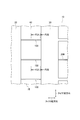
- FIG. 1 is a partial plan development view of a tread of the pneumatic tire 10.
- FIG. 2 is a partially enlarged plan view of the tread 15 of the pneumatic tire 10.
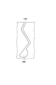
- 3A is a cross-sectional view of the block 40 taken along line F3A-F3A in FIG.
- 3B is a cross-sectional view of the block 40 taken along line F3B-F3B in FIG.
- FIG. 4 is an enlarged cross-sectional view of the sipe 100 formed in the block 40.
- FIG. 5A is a diagram illustrating a modified example of the sipe 100.
- FIG. 5B is a diagram illustrating a modification of the sipe 100.
- FIG. 5C is a diagram illustrating a modified example of the sipe 100.
- FIG. 6 is a diagram showing a modified example of the block 40.
- FIG. 1 is a partial plan development view of a tread of a pneumatic tire 10 according to the present embodiment.
- the pneumatic tire 10 has a tread 15 in contact with a road surface.
- the pneumatic tire 10 has a tread pattern that is symmetrical in the tire width direction with respect to the tire equator line CL.
- the tread 15 is formed with a plurality of circumferential grooves extending in the tire circumferential direction, specifically, a circumferential groove 20 and a circumferential groove 30.
- a block 40 extending in the tire circumferential direction is provided between the circumferential groove 20 and the circumferential groove 30.
- a block 50 is provided on the outer side in the tire width direction of the circumferential groove 30.
- a block 60 is provided at a position overlapping the tire equator line CL. As described above, the blocks 40, 50, and 60 substantially constitute the tread 15.
- the block 40 is offset from the tire equator line CL, but is provided on the inner side in the tire width direction.
- the block 50 is provided in a region on the outer side in the tire width direction of the tread 15, specifically, a tread shoulder.
- the pneumatic tire 10 is a tire that can be used for a four-wheeled vehicle such as a passenger car, and includes a carcass ply that forms a skeleton of the pneumatic tire 10, a pair of bead portions assembled in a rim hole, and a carcass.
- a belt layer (not shown) provided outside the ply in the tire radial direction is provided.
- the pneumatic tire 10 generally adopts a radial structure, but is not necessarily limited to the radial structure. That is, a bias structure may be used.
- the shape (tread pattern) of the tread 15 shown in FIG. 1 is only one example, and the shape and number of the blocks and grooves (circumferential grooves or width grooves) are not particularly limited.
- FIG. 2 is a partially enlarged plan view of the tread 15 of the pneumatic tire 10 shown in FIG.
- a plurality of sipes 100 are formed in the block 40.
- the sipe 100 is also formed in the block 60 (see FIG. 1).
- the sipe 100 extends in a predetermined direction in the tread surface view.
- the sipe 100 extends substantially parallel to the tire width direction.
- the sipe 100 is linear in the tread surface view and crosses the block 40 (block 60). That is, the end of the sipe 100 in the tire width direction communicates with the circumferential groove 20 and the flange 30.
- a plurality of sipes 200 are formed in the block 50 provided on the tread shoulder.
- the sipe 200 also extends substantially parallel to the tire width direction.
- the sipe 200 is linear in the tread surface view.
- the end of the sipe 200 on the inner side in the tire width direction communicates with the circumferential groove 30.
- the end of the sipe 200 on the outer side in the tire width direction opens at the shoulder end of the tread 15.
- the sipe 200 is not a zigzag shape in which a predetermined amplitude is repeated in the tire circumferential direction with reference to a tire radial direction as will be described later, but a simple planar shape.
- FIG. 3A is a cross-sectional view of the block 40 taken along line F3A-F3A in FIG. 3B is a cross-sectional view of the block 40 taken along line F3B-F3B in FIG.
- FIG. 3A shows the shape of the sipe 100 at the center of the block 40 in the tire width direction.
- FIG. 3B shows the shape of the sipe 100 on the end side in the tire width direction of the block 40.
- the shape (size) of the widened portion 160 is different between FIGS. 3A and 3B.
- the sipe 100 includes a first inclined part 110, a second inclined part 120, a bent part 130, a bent part 140, and a widened part 160.
- the first inclined part 110 and the second inclined part 120 are linear.
- the second inclined portion 120 is formed on the outer side in the tire radial direction than the first inclined portion 110.
- the first inclined portion 110 and the second inclined portion 120 are not parallel to the tire radial direction but are inclined with respect to the tire radial direction.
- the second inclined portion 120 is inclined to the opposite side of the first inclined portion 110 with respect to the tire radial direction. Further, the portion of the sipe 100 on the outer side in the tire radial direction from the bent portion 140, specifically, the portion of the sipe 100 formed near the tread surface of the block 40 is inclined in the same direction as the first inclined portion 110. Yes.
- the bent portion 130 is formed on the inner side in the tire radial direction, and the bent portion 140 is formed on the outer side in the tire radial direction with respect to the bent portion 130. That is, the sipe 100 has a plurality of bent portions in the depth direction of the sipe 100 (tire radial direction).
- the amplitude of the bent portion 130 and the bent portion 140 in the tire circumferential direction is slight, it is the largest in the tire width direction of the block 40, that is, the central region in the tire width direction of the sipe 100 (see FIGS. 3A and 3B). I want to compare).
- the bent portion 130 communicates with the first inclined portion 110 and the second inclined portion 120. Further, the bent portion 130 is bent so as to be convex with respect to the direction in which the interval between the first inclined portion 110 and the second inclined portion 120 is narrowed. Specifically, as shown in FIGS. 3A and 3B, the bent portion 130 bends so as to be convex toward one side in the tire circumferential direction (convex direction Dc in the drawing).
- Such a sipe having two bent portions may be called an M-shaped sipe or the like because of the similarity in shape.
- the widened portion 160 has a groove width (sipe width) wider than that of the other parts constituting the sipe 100.
- the widened portion 160 is formed on the inner side in the tire radial direction than the first inclined portion 110. Specifically, the widened portion 160 is formed at the bottom portion of the sipe 100, that is, the deepest portion in the depth direction.
- the widened portion 160 communicates with the first inclined portion 110 and has a wider groove width than the first inclined portion 110.
- the widened portion 160 is formed on the bent portion 130 side with the extending direction of the first inclined portion 110 as a reference. Specifically, the widened portion 160 is formed on the convex direction Dc side where the bent portion 130 is convex. That is, the widened portion 160 widens from the boundary with the first inclined portion 110 (which may be referred to as a widening start point) toward the bent portion 130 side (the convex direction Dc side).
- the widened portion 160 is not widened on the opposite side with respect to the extending direction of the first inclined portion 110. That is, on the opposite side of the convex direction Dc where the bent portion 130 is convex, the widened portion 160 extends along the extending direction of the first inclined portion 110 without being particularly widened.
- a sipe in which such a widened portion is formed at the deepest portion in the depth direction may be referred to as a flask-type sipe because of the similarity in shape.
- the widened portion 160 is formed in a section from the deepest portion in the depth direction of the sipe 100 to the bent portion 130 formed on the innermost side in the tire radial direction.
- the size (size) of the widened portion 160 changes in the tire width direction (predetermined direction). Specifically, as shown in FIGS. 3A and 3B, the size of the widened portion 160 along the convex direction Dc in which the bent portion 130 is convex varies in the tire width direction, and the size of the sipe 100 in the tire width direction. Maximum in the central region.
- the range in which the size of the widened portion 160 is maximized is 50% or less of the width in the tire width direction of the sipe 100 (similar to the width of the block 40 in the present embodiment) in consideration of the improvement in drainage described later. It is preferable to do.
- the widened portion 160 has a generally triangular shape when the sipe 100 is viewed from the side. That is, the width of the widened portion 160 becomes wider toward the inner side in the tire radial direction.
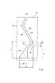
- FIG. 4 is an enlarged cross-sectional view of the sipe 100 formed in the block 40.
- the first inclined portion 110 of the sipe 100 is substantially formed by the wall surfaces of the blocks 40 facing each other.
- the first inclined portion 110 is formed by the wall surface 41a and the wall surface 41b of the block 40.
- the wall surface 41a is located on the inner side in the tire radial direction
- the wall surface 41b is located on the outer side in the tire radial direction of the wall surface 41a.
- the wall surface 41a is located on the convex direction Dc side
- the wall surface 41b is located on the opposite side of the convex direction Dc.
- the second inclined portion 120 of the sipe 100 is also substantially formed by the wall surfaces of the blocks 40 facing each other.
- the second inclined portion 120 is formed by the wall surface 42a and the wall surface 42b of the block 40.
- the wall surface 42b is located on the inner side in the tire radial direction, and the wall surface 42a is located on the outer side in the tire radial direction of the wall surface 42b.
- the wall surface 42a is located on the convex direction Dc side, and the wall surface 42b is located on the opposite side of the convex direction Dc.
- the block 40 has a wall surface forming portion 41 that forms a wall surface 41a on the inner side in the tire radial direction of the first inclined portion 110. That is, the wall surface forming portion 41 is a partial region of the block 40 and is adjacent to the widened portion 160.
- the wall surface forming portion 41 can contact the wall surface 41b on the outer side in the tire radial direction of the first inclined portion 110 over a predetermined range when a load is applied.
- the wall surface forming portion 41 has a wall surface extending over the portion where the wall surface 41a is formed, that is, the range from the bent portion 130 to the boundary between the first inclined portion 110 and the widened portion 160 (the widening start point). Can contact 41b.
- the wall surface 42 b forming the first inclined portion 110 extends along the extending direction (inclined direction) of the first inclined portion 110 and reaches the widened portion 160. That is, the wall surface 42b is linear and forms the wall surface of the widened portion 160 on the opposite side of the convex direction Dc along the extending direction of the first inclined portion 110.
- a ratio h2 / h1 to a height h2 of the portion 160 on the outer side in the tire radial direction is 0.5 or more and 0.8 or less.
- h2 / h1 is preferably 0.7 or more and 0.8 or less.
- the ratio w2 / w1 with the width w2 along the line is 0.5 or more and 0.8 or less.
- the inclination angle (acute angle side) of the first inclined portion 110 and the second inclined portion 120 with respect to the tire radial direction is preferably 35 ° or more and 50 ° or less.
- variety of the 1st inclination part 110 and the 2nd inclination part 120 is 0.1 mm or more and 0.4 mm or less.
- the rigidity improvement effect of the block 40 due to the meshing of the wall surfaces of the sipe 100 is likely to occur from the center in the tire radial direction of the sipe 100 on the ground contact surface side.
- a gap widthened portion
- the opposing wall surfaces do not contact each other, drainage can be improved while maintaining the rigidity of the block 40. This is because the gap has a sufficient capacity (volume) to store rainwater.
- a gap (widened portion) is formed in the section from the bottom portion of the sipe 100, that is, the end portion on the inner side in the tire radial direction to the bent portion 130 closest to the end portion. Further, the size (size) of the widened portion 160 is maximized in the central region of the sipe 100 in the tire width direction.
- the size of the widened portion 160 in the convex direction Dc varies with the amplitude of the bent portions 130 and 140 (particularly, the bent portion 130) in the side view of the sipe 100.
- the size of the widened portion 160 is also increased.
- the size of the widened portion 160 is also decreased.
- rainwater can be effectively stored in the widened portion 160 in the central region in the tire width direction of the sipe 100 farthest from the circumferential grooves 20 and 30. Furthermore, when the degree of meshing of the wall surface of the sipe 100 is increased by the load applied to the block 40, rainwater stored in the widened portion 160 is likely to be discharged to the circumferential grooves 20, 30 and the like at a high flow rate.
- the widened portion 160 of the sipe 100 is made too large with respect to the amplitude of the bent portion, a large resistance is generated when the blade for forming the sipe 100 is pulled out from the block 40 during vulcanization of the pneumatic tire 10. Therefore, it is not preferable.
- Tables 1 and 2 show the results of the evaluation test.
- the presence / absence of the “sipe widening portion” shown in Tables 1 and 2 means whether or not the widening portion 160 described above is formed.
- h2 / h1 and w2 / w1 are as shown in FIG.
- Test tire size 245 / 45R17 ⁇ Evaluation method: A vehicle equipped with the tires to be tested was run on a wet road test course, and the test driver evaluated the steering stability in a sensory manner. ⁇ Evaluation criteria: Numerical value based on a maximum of 10 points (the larger the numerical value, the better the steering stability)
- sipe widening portion 160 is preferably large from the viewpoint of drainage, but if it exceeds the height h1 or the width w1, it is difficult to ensure sufficient block rigidity.
- the widened portion 160 is formed in the sipe 100, and the widened portion 160 communicates with the first inclined portion 110 and is based on the extending direction of the first inclined portion 110.
- a bent portion 130 side (convex direction Dc).
- the widened portion 160 is formed only on the bent portion 130 side, it is difficult for the block 40 (block 60, hereinafter the same) to fall down. Specifically, as described above, since the widened portion 160 is formed only on the bent portion 130 side, local deformation of the block 40 is suppressed at the bottom portion of the sipe 100.
- the wall surface forming portion 41 adjacent to the widened portion is a predetermined range from the wall surface 41b on the outer side in the tire radial direction of the first inclined portion 110 when a load is applied, specifically, from the bent portion 130 to the first inclined portion 110 and the widened portion. It is possible to contact over a range up to the boundary with 160 (widening start point).
- the steering stability on the wet road surface can be further improved while the bent sipe 100 is formed on the block 40.
- h2 / h1 is 0.5 or more and 0.8 or less with respect to the size of the widened portion 160. Further, w2 / w1 is 0.5 or more and 0.8 or less (see FIG. 4). According to the widened portion 160 having such a size, the drainage performance and the block rigidity can be ensured at a higher level, and the steering stability on the wet road surface can be further enhanced.
- one end in the extending direction (tire width direction) of the sipe 100 communicates with the circumferential groove 20.
- the other end of the sipe 100 in the extending direction communicates with the circumferential groove 30.
- the size of the widened portion 160 changes in the tire width direction (predetermined direction) and is maximized in the central region of the sipe 100 in the tire width direction.
- the sipe 200 formed in the block 50 provided on the tread shoulder does not have the widened portion 160 like the sipe 100, and the shape is also planar. A large lateral force is easily input to the block 50 provided on the tread shoulder when the vehicle turns, but according to the pneumatic tire 10, a simple flat sipe 200 is formed on the block 50. In addition, it is possible to improve steering stability on a wet road surface while suppressing damage to the block 50 and the like.
- the shape of the sipe 100 may be changed as follows. 5A to 5C show a modification of the sipe 100.
- the widened portion 160 of the sipe 100 has a triangular shape in the side view of the sipe 100, but as illustrated in FIG. 5A, the widened portion 160A of the sipe 100A is compared with the widened portion 160.
- the wall surface forming part 41 is long, and the area where the wall surface of the sipe 100A meshes increases. For this reason, the rigidity of the block can be further increased.
- the widened portion 160B of the sipe 100B has a semicircular shape. According to the sipe 100B, since the widened portion 160B has a semicircular shape, it is difficult to become resistance when the blade for forming the sipe 100B is pulled out during tire vulcanization.
- the widened portion 160C of the sipe 100C has the same shape as the widened portion 160 of the sipe 100A.
- the sipe 100C has only one bent portion 135.
- the bent portion 135 is formed at substantially the center in the tire radial direction of the sipe 100C.
- shapes of the plurality of sipes formed in the block 40 described above may be changed as follows.
- FIG. 6 shows a modification of the block 40. Specifically, FIG. 6 corresponds to FIG. 3A and is a cross-sectional view of the block 40A along the tire circumferential direction and the tire radial direction.
- sipes 100 and sipes 100D are alternately formed in the tire circumferential direction in the block 40A.
- the sipe 100D has a widened portion 160D having the same shape as the widened portion 160.
- the widened portion 160D (first sipe) widens in the tire rotation direction R with reference to the extending direction of the first inclined portion 110.
- the widened portion 160 (second sipe) widens in the direction opposite to the tire rotation direction R with reference to the extending direction of the first inclined portion 110.
- the sipe 100 and the sipe 100D have symmetrical shapes in the cross section along the tire circumferential direction and the tire radial direction. That is, the shape of the sipe 100 inverted is the shape of the sipe 100D.
- the sipe 100 and the sipe 100D are alternately formed in the tire circumferential direction, that is, the tire rotation direction.
- the sipe 100 and sipe 100D have different directions of the widened portion, so the robustness against both acceleration and braking of the vehicle can be improved, and on average both high steering stability during acceleration and braking Can be demonstrated.
- the widened portion 160 is formed at the bottom portion of the sipe 100.
- the widened portion 160 is not necessarily formed at the bottom portion of the sipe 100.
- a sipe having a width as short as the first inclined portion 110 may be formed on the inner side in the tire radial direction from the widened portion 160, that is, at a deeper position in the depth direction of the sipe 100.
- the sipe 100 extends in the tire width direction, but the extending direction of the sipe 100 is not particularly limited. That is, the extending direction of the sipe 100 may be inclined with respect to the tire width direction, or may extend in the tire circumferential direction.
- the sipe 100 only needs to communicate with either the circumferential groove 20 or the circumferential groove 30. Alternatively, the sipe 100 does not necessarily need to communicate with the circumferential groove 20 and the circumferential groove 30.
- the sipe 100 may not be linear, for example, it may be slightly curved or meandering.
- the first inclined part 110 and the second inclined part 120 are not necessarily linear.
- the above-described tire is useful because it can further improve steering stability on a wet road surface while forming a bent sipe in the block.
Landscapes
- Engineering & Computer Science (AREA)
- Mechanical Engineering (AREA)
- Tires In General (AREA)
Abstract
空気入りタイヤのブロック(40)に形成されるサイプ(100)は、タイヤ径方向に対して傾斜する第1傾斜部(110)と、第1傾斜部(110)よりもタイヤ径方向外側に形成され、タイヤ径方向に対して第1傾斜部(110)と逆側に傾斜する第2傾斜部(120)と、第1傾斜部(110)と第2傾斜部(120)とに連通し、第1傾斜部(110)と第2傾斜部(120)との間隔が狭くなる方向に対して凸となるように屈曲する屈曲部(130)と、第1傾斜部(110)よりもタイヤ径方向内側に形成され、第1傾斜部(110)よりも溝幅が広がった拡幅部(160)とを有する。拡幅部(160)は、第1傾斜部(110)と連通するとともに、第1傾斜部(110)の延在方向を基準として屈曲部(130)側に形成される。
Description
本発明は、路面と接するトレッドにサイプが形成されたタイヤに関する。
空気入りタイヤ(以下、タイヤ)において、ウェット路面での高い操縦安定性を発揮するためには、排水性と接地性との両立が重要である。排水性と接地性との両立を図るために、トレッドを構成するブロックにサイプを形成する方法が広く用いられている。
特に、サイプの形状を単純な平面状ではなく、タイヤ径方向及びタイヤ幅方向の少なくとも一方において変化させた屈曲状、具体的には、ジグザグ状のサイプが知られている(例えば、特許文献1)。
このようなサイプによれは、ブロックにおける溝体積が増大し、雨水を貯える、いわゆる貯水効果が得られる。また、ジグザグ状のサイプの対向する壁面が噛み合うため、ブロックの変形(倒れ込み)が抑制される。
このようなジグザグ状のサイプにおいて、さらに排水性を高めるため、サイプの底部分にタイヤ周方向に延びる空隙部を形成したタイヤも知られている(例えば、特許文献2)。具体的には、特許文献2には、サイプ(スリット)の底部が円管状の空隙部(チャネル)と連通した形状が示されている。
上述したサイプの壁面の噛み合いは、トレッド(ブロック)が路面に接地して圧縮変形を受けた際に、サイプの壁面部分が膨出変形することによって生じる。また、この膨出変形の程度は、サイプの部位によって異なるため、サイプ全体として効果的な噛み合いが生じるように、サイプの形状を変化させている。
これにより、ブロックの剛性を確保し、ブロックの接地性を向上させ得る。一方で、ブロックが路面と接地している場合、対向するサイプの壁面同士が接触するため、実質的なサイプの溝体積が減少し、排水性が低下する問題がある。
また、上述した特許文献2に開示されているサイプのように、サイプの底部に大きな空隙部を形成してしまうと、ブロックが路面と接地している場合、ブロックがタイヤ径方向内側に大きく変形してしまい、ブロックの接地性が低下する問題がある。
そこで、本発明は、このような状況に鑑みてなされたものであり、ブロックに屈曲状のサイプを形成しつつ、ウェット路面での操縦安定性をさらに向上させたタイヤの提供を目的とする。
本発明の一態様は、路面と接するトレッド(トレッド15)を構成するブロック(ブロック40, 60)に、トレッド面視において所定方向(タイヤ幅方向)に延在するサイプ(例えば、サイプ100)が形成されたタイヤ(空気入りタイヤ10)であって、前記サイプは、タイヤ径方向に対して傾斜する第1傾斜部(第1傾斜部110)と、前記第1傾斜部よりもタイヤ径方向外側に形成され、タイヤ径方向に対して前記第1傾斜部と逆側に傾斜する第2傾斜部(第2傾斜部120)と、前記第1傾斜部と前記第2傾斜部とに連通し、前記第1傾斜部と前記第2傾斜部との間隔が狭くなる方向に対して凸となるように屈曲する屈曲部(屈曲部130)と、前記第1傾斜部よりもタイヤ径方向内側に形成され、前記第1傾斜部よりも溝幅が広がった拡幅部(拡幅部160)とを有し、前記拡幅部は、前記第1傾斜部と連通するとともに、前記第1傾斜部の延在方向を基準として前記屈曲部側に形成される。
以下、実施形態を図面に基づいて説明する。なお、同一の機能や構成には、同一または類似の符号を付して、その説明を適宜省略する。
(1)タイヤの全体概略構成
図1は、本実施形態に係る空気入りタイヤ10のトレッドの一部平面展開図である。図1に示すように、空気入りタイヤ10は、路面と接するトレッド15を有する。空気入りタイヤ10は、タイヤ赤道線CLを基準として、タイヤ幅方向において対称なトレッドパターンを有する。
図1は、本実施形態に係る空気入りタイヤ10のトレッドの一部平面展開図である。図1に示すように、空気入りタイヤ10は、路面と接するトレッド15を有する。空気入りタイヤ10は、タイヤ赤道線CLを基準として、タイヤ幅方向において対称なトレッドパターンを有する。
トレッド15には、タイヤ周方向に延びる複数の周方向溝、具体的には、周方向溝20及び周方向溝30が形成される。周方向溝20と周方向溝30との間には、タイヤ周方向に延びるブロック40が設けられる。また、周方向溝30のタイヤ幅方向外側には、ブロック50が設けられる。さらに、タイヤ赤道線CLと重複する位置には、ブロック60が設けられる。このように、ブロック40, 50, 60は、実質的にトレッド15を構成する。
ブロック40は、タイヤ赤道線CLからオフセットしているが、タイヤ幅方向内側に設けられる。一方、ブロック50は、トレッド15のタイヤ幅方向外側の領域、具体的には、トレッドショルダーに設けられる。
なお、本実施形態では、空気入りタイヤ10は、乗用自動車などの四輪自動車に用い得るタイヤであり、空気入りタイヤ10の骨格を形成するカーカスプライ、リムホールに組み付けられる一対のビード部、及びカーカスプライのタイヤ径方向外側に設けられるベルト層など(何れも不図示)を備える。
空気入りタイヤ10は、一般的には、ラジアル構造を採用するが、必ずしもラジアル構造に限定されない。つまり、バイアス構造であっても構わない。また、図1に示すトレッド15の形状(トレッドパターン)は、実施例の一つに過ぎず、ブロック及び溝(周方向溝または幅方向溝)の形状及び数は、特に限定されない。
図2は、図1に示した空気入りタイヤ10のトレッド15の一部拡大平面図である。図1及び図2に示すように、ブロック40には、複数のサイプ100が形成される。同様に、ブロック60にもサイプ100が形成される(図1参照)。
サイプ100は、トレッド面視において所定方向に延在する。本実施形態では、サイプ100は、タイヤ幅方向と略平行に延在する。サイプ100は、トレッド面視において、直線状あり、ブロック40(ブロック60)を横断する。つまり、サイプ100のタイヤ幅方向の端部は、周方向溝20, 30に連通する。
また、トレッドショルダーに設けられるブロック50には、複数のサイプ200が形成される。本実施形態では、サイプ200もタイヤ幅方向と略平行に延在する。また、サイプ200は、トレッド面視において直線状である。サイプ200のタイヤ幅方向内側の端部は、周方向溝30に連通する。一方、サイプ200のタイヤ幅方向外側の端部は、トレッド15のショルダー端に開口する。
サイプ200は、サイプ100と比較すると、後述するようなタイヤ径方向を基準として、タイヤ周方向に所定の振幅を繰り返すようなジグザグ状ではなく、単純な平面状である。
(2)サイプの形状
図3Aは、図2のF3A-F3A線に沿ったブロック40の断面図である。図3Bは、図2のF3B-F3B線に沿ったブロック40の断面図である。
図3Aは、図2のF3A-F3A線に沿ったブロック40の断面図である。図3Bは、図2のF3B-F3B線に沿ったブロック40の断面図である。
図3Aは、ブロック40のタイヤ幅方向における中央でのサイプ100の形状を示す。一方、図3Bは、ブロック40のタイヤ幅方向における端部側でのサイプ100の形状を示す。後述するように、図3Aと図3Bとでは、拡幅部160の形状(大きさ)が異なる。
図3A及び図3Bに示すように、サイプ100は、第1傾斜部110、第2傾斜部120、屈曲部130、屈曲部140及び拡幅部160を有する。
第1傾斜部110及び第2傾斜部120は、直線状である。第2傾斜部120は、第1傾斜部110よりもタイヤ径方向外側に形成される。第1傾斜部110及び第2傾斜部120は、タイヤ径方向と平行ではなく、タイヤ径方向に対して傾斜している。
但し、第2傾斜部120は、タイヤ径方向に対して第1傾斜部110と逆側に傾斜する。また、屈曲部140よりもタイヤ径方向外側におけるサイプ100の部分、具体的には、ブロック40の踏面寄りに形成されているサイプ100の部分は、第1傾斜部110と同じ方向に傾斜している。
屈曲部130は、タイヤ径方向内側に形成され、屈曲部140は、屈曲部130よりもタイヤ径方向外側に形成される。つまり、サイプ100は、サイプ100の深さ方向(タイヤ径方向)において複数の屈曲部を有する。
また、屈曲部130及び屈曲部140のタイヤ周方向における振幅は、僅かであるが、ブロック40のタイヤ幅方向、つまり、サイプ100のタイヤ幅方向における中央領域で最も大きい(図3Aと図3Bを比較されたい)。
屈曲部130は、第1傾斜部110と第2傾斜部120とに連通する。また、屈曲部130は、第1傾斜部110と第2傾斜部120との間隔が狭くなる方向に対して凸となるように屈曲する。具体的には、屈曲部130は、図3A及び図3Bに示すように、タイヤ周方向における一方側に向かって凸となるように屈曲する(図中の凸方向Dc)。
なお、このような2つの屈曲部を有するサイプは、その形状の類似性から、M字サイプなどと呼ばれてもよい。
拡幅部160は、サイプ100を構成する他の部分よりも溝幅(サイプ幅)が広がっている。拡幅部160は、第1傾斜部110よりもタイヤ径方向内側に形成される。具体的には、拡幅部160は、サイプ100の底部分、つまり、深さ方向の最深部に形成される。
また、図3A及び図3Bに示すように、拡幅部160は、第1傾斜部110と連通するとともに、第1傾斜部110よりも溝幅が広がっている。
拡幅部160は、第1傾斜部110の延在方向を基準として屈曲部130側に形成される。具体的には、拡幅部160は、屈曲部130が凸となっている凸方向Dc側に形成される。つまり、拡幅部160は、第1傾斜部110との境界(拡幅開始点と呼んでもよい)から屈曲部130側(凸方向Dc側)に向かって拡幅している。
一方、拡幅部160は、第1傾斜部110の延在方向を基準とした逆側には拡幅していない。つまり、屈曲部130が凸となっている凸方向Dcの逆側では、拡幅部160は、特に拡幅せずに、第1傾斜部110の延在方向に沿って延びている。
なお、このような拡幅部が深さ方向の最深部に形成されたサイプは、その形状の類似性から、フラスコ型サイプなどと呼ばれてもよい。
拡幅部160は、サイプ100の深さ方向の最深部から、最もタイヤ径方向内側に形成されている屈曲部130までの区間に形成される。
また、拡幅部160のサイズ(大きさ)は、タイヤ幅方向(所定方向)において変化する。具体的には、図3A及び図3Bに示すように、屈曲部130が凸となる凸方向Dcに沿った拡幅部160のサイズは、タイヤ幅方向において変化するとともに、タイヤ幅方向におけるサイプ100の中央領域において最大となる。
なお、拡幅部160のサイズが最大となる範囲は、後述する排水性の向上を考慮すると、サイプ100のタイヤ幅方向における幅(本実施形態では、ブロック40の幅と同様)の50%以下とすることが好ましい。
本実施形態では、拡幅部160は、サイプ100の側方視において、概ね三角形状である。つまり、拡幅部160の幅は、タイヤ径方向内側に向かうに連れて広くなる。
図4は、ブロック40に形成されるサイプ100の拡大断面図である。図4に示すように、サイプ100の第1傾斜部110は、互いに対向するブロック40の壁面によって実質的に形成される。具体的には、第1傾斜部110は、ブロック40の壁面41a及び壁面41bによって形成される。壁面41aは、タイヤ径方向内側に位置し、壁面41bは、壁面41aのタイヤ径方向外側に位置する。また、壁面41aは、凸方向Dc側に位置し、壁面41bは、凸方向Dcの逆側に位置する。
同様に、サイプ100の第2傾斜部120も、互いに対向するブロック40の壁面によって実質的に形成される。具体的には、第2傾斜部120は、ブロック40の壁面42a及び壁面42bによって形成される。壁面42bは、タイヤ径方向内側に位置し、壁面42aは、壁面42bのタイヤ径方向外側に位置する。また、壁面42aは、凸方向Dc側に位置し、壁面42bは、凸方向Dcの逆側に位置する。
ブロック40は、第1傾斜部110のタイヤ径方向内側の壁面41aを形成する壁面形成部41を有する。つまり、壁面形成部41は、ブロック40の一部の領域であり、拡幅部160とも隣接する。
壁面形成部41は、荷重負荷時に第1傾斜部110のタイヤ径方向外側の壁面41bと所定範囲に亘って接触し得る。具体的には、壁面形成部41は、壁面41aが形成されている部分、つまり、屈曲部130から第1傾斜部110と拡幅部160との境界(拡幅開始点)までの範囲に亘って壁面41bと接触し得る。
また、第1傾斜部110を形成する壁面42bは、第1傾斜部110の延在方向(傾斜方向)に沿って延びており、拡幅部160に到達する。つまり、壁面42bは、直線状であり、第1傾斜部110の延在方向に沿って、凸方向Dcと逆側の拡幅部160の壁面を構成する。
本実施形態では、タイヤ径方向に沿ったサイプ100のタイヤ径方向内側の端部から屈曲部130までの高さh1と、タイヤ径方向に沿ったサイプ100のタイヤ径方向内側の端部から拡幅部160のタイヤ径方向外側の端部までの高さh2との比h2/h1は、0.5以上、0.8以下である。なお、h2/h1は、0.7以上、0.8以下であることが好ましい。
また、屈曲部130が凸となる凸方向Dcに沿ったサイプ100のタイヤ径方向内側の端部から屈曲部130までの幅w1と、タイヤ径方向内側の端部における拡幅部160の凸方向Dcに沿った幅w2との比w2/w1は、0.5以上、0.8以下である。
さらに、第1傾斜部110及び第2傾斜部120のタイヤ径方向に対する傾斜角度(鋭角側)は、35°以上、50°以下であることが好ましい。また、第1傾斜部110及び第2傾斜部120の幅は、0.1mm以上、0.4mm以下であることが好ましい。
(3)作用・効果
次に、上述した空気入りタイヤ10の作用効果について説明する。サイプ100を形成する壁面(壁面41a, 41b, 42a, 42b)の接触挙動を観察した結果、サイプ100の底部分では、荷重負荷時でも壁面の膨出変形が少ないため、壁面接触が生じていないことが確認された。
次に、上述した空気入りタイヤ10の作用効果について説明する。サイプ100を形成する壁面(壁面41a, 41b, 42a, 42b)の接触挙動を観察した結果、サイプ100の底部分では、荷重負荷時でも壁面の膨出変形が少ないため、壁面接触が生じていないことが確認された。
つまり、サイプ100の壁面の噛み合いによるブロック40の剛性向上効果は、サイプ100のタイヤ径方向における中央から接地面側で生じ易い。そこで、サイプ100の底部分に、対向する壁面が接触しないような空隙(拡幅部)を設けることによって、ブロック40の剛性を維持しつつ、排水性を向上できる。当該空隙は、雨水を貯えるために十分な容量(体積)を有するためである。
上述した実施形態では、サイプ100の底部分、つまり、タイヤ径方向内側の端部から、当該端部に最も近い屈曲部130までの区間に空隙(拡幅部)が形成されている。また、拡幅部160のサイズ(大きさ)は、タイヤ幅方向におけるサイプ100の中央領域において最大となる。
また、拡幅部160の凸方向Dcにおけるサイズは、サイプ100の側方視において、屈曲部130, 140(特に、屈曲部130)の振幅の大きさに連れて変化する。
より具体的には、当該屈曲部の振幅が大きくなれば、拡幅部160のサイズも大きくし、当該屈曲部の振幅が小さくなれば、拡幅部160のサイズも小さくなる。
これにより、周方向溝20, 30から最も離れているサイプ100のタイヤ幅方向における中央領域において効果的に拡幅部160に雨水を貯えることができる。さらに、ブロック40への荷重負荷によって、サイプ100の壁面の噛み合い程度が強まると、拡幅部160に貯えられた雨水は、速い流速で周方向溝20, 30などに排出され易い。
また、サイプ100の拡幅部160を当該屈曲部の振幅に対して大きくし過ぎると、空気入りタイヤ10の加硫時に、サイプ100を形成するためのブレードをブロック40の部分から引き抜く際に大きな抵抗となるため、好ましくない。
ここで、表1及び表2は、評価試験の結果を示す。


表1及び表2に示す「サイプ拡幅部」の有無とは、上述した拡幅部160が形成されているか否かを意味する。h2/h1及びw2/w1は、図4に示したとおりである。
評価試験の条件及び方法は、次のとおりである。
・ 試験タイヤサイズ: 245/45R17
・ 評価方法: 試験対象タイヤを装着した車両でウェット路面のテストコースを走行し、テストドライバーが操縦安定性を官能で評価した。
・ 評価基準: 10点満点による数値(数値が大きい程、操縦安定性が良好)
・ 評価方法: 試験対象タイヤを装着した車両でウェット路面のテストコースを走行し、テストドライバーが操縦安定性を官能で評価した。
・ 評価基準: 10点満点による数値(数値が大きい程、操縦安定性が良好)
表1及び表2に示すように、サイプ拡幅部(拡幅部160)が形成されたサイプを備え、h2/h1及びw2/w1が一定の範囲内(実施例1~6参照)の場合、ウェット路面操縦安定性が大きく向上している。サイプ拡幅部(空隙)は、排水性の観点からは、大きいことが好ましいが、高さh1または幅w1を超えると、十分なブロックの剛性を確保することが難しくなる。
この理由は、サイプ拡幅部が大きくなり過ぎると、本来、サイプの壁面の噛み合いが生じる領域まで空隙となってしまい、ブロックの変形(倒れ込み)を生じさせてしまうためである。さらに、サイプ100の底部分で局所的なブロックの変形が大きくなり、やはり、ブロックの変形を生じさせてしまうためである。この結果、ブロックの接地性が低下し、特に、ウェット路面での操縦安定性が損なわれる。
このように、空気入りタイヤ10によれば、サイプ100には、拡幅部160が形成され、拡幅部160は、第1傾斜部110と連通するとともに、第1傾斜部110の延在方向を基準として屈曲部130側(凸方向Dc)に形成される。
このため、溝幅が広がった拡幅部160によって、十分な雨水を貯え、周方向溝20, 30などを介して雨水を排水することができる。これにより、排水性が向上する。
また、拡幅部160は、屈曲部130側のみに形成されるため、ブロック40(ブロック60、以下同)の倒れ込み変形を生じさせ難い。具体的には、上述したように、拡幅部160は、屈曲部130側のみに形成されるため、サイプ100の底部分で局所的なブロック40の変形が抑制される。
さらに、拡幅部に隣接する壁面形成部41は、荷重負荷時に第1傾斜部110のタイヤ径方向外側の壁面41bと所定範囲、具体的には、屈曲部130から第1傾斜部110と拡幅部160との境界(拡幅開始点)までの範囲に亘って接触し得る。
このため、拡幅部160を形成しつつ、壁面41aと壁面41bとの噛み合いを生じさせることができ、ブロック40の変形が抑制される。これにより、ブロック40の剛性が維持でき、操縦安定性を損なわない。
すなわち、空気入りタイヤ10によれば、ブロック40に屈曲状のサイプ100を形成しつつ、ウェット路面での操縦安定性をさらに向上できる。
本実施形態では、拡幅部160のサイズに関して、h2/h1は、0.5以上、0.8以下である。また、w2/w1は、0.5以上、0.8以下である(図4参照)。このようなサイズの拡幅部160によれば、排水性とブロック剛性の確保とをより高い次元で実現でき、ウェット路面の操縦安定性をさらに高められる。
本実施形態では、サイプ100の延在方向(タイヤ幅方向)における一端は、周方向溝20に連通する。また、サイプ100の延在方向における他端は、周方向溝30に連通する。
このため、サイプ100の拡幅部160に貯えられた雨水を効率的にブロック40の外に排出できる。これにより、排水性をさらに高められる。
本実施形態では、拡幅部160のサイズは、タイヤ幅方向(所定方向)において変化するとともに、タイヤ幅方向におけるサイプ100の中央領域において最大となる。
このため、上述したように、サイプ100のタイヤ幅方向における中央領域において効果的に拡幅部160に雨水を貯えることができ、サイプ100の壁面の噛み合い程度が強まると、ポンプ的な効果が生じ、拡幅部160に貯えられた雨水は、速い流速で周方向溝20, 30などに排出され易い。これにより、排水性をさらに高められる。
本実施形態では、トレッドショルダーに設けられるブロック50に形成されるサイプ200は、サイプ100のような拡幅部160も有しておらず、形状も平面状である。トレッドショルダーに設けられるブロック50には、車両の旋回時などに大きな横力が入力され易いが、空気入りタイヤ10によれば、ブロック50には、単純な平面状のサイプ200が形成されるため、ブロック50の損傷などを抑制しつつ、ウェット路面での操縦安定性を高め得る。
(4)その他の実施形態
以上、実施例に沿って本発明の内容を説明したが、本発明はこれらの記載に限定されるものではなく、種々の変形及び改良が可能であることは、当業者には自明である。
以上、実施例に沿って本発明の内容を説明したが、本発明はこれらの記載に限定されるものではなく、種々の変形及び改良が可能であることは、当業者には自明である。
例えば、サイプ100の形状は、次のように変更してもよい。図5A~図5Cは、サイプ100の変形例を示す。図5A~図5Cに示すサイプ100A、サイプ100B及びサイプ100Cでは、サイプ100と比較すると、拡幅部の形状が異なる。
具体的には、サイプ100の拡幅部160は、サイプ100の側方視において、三角形状であったが、図5Aに示すように、サイプ100Aの拡幅部160Aは、拡幅部160と比較すると、壁面形成部41が長く、サイプ100Aの壁面が噛み合う領域が増大する。このため、ブロックの剛性をさらに高め得る。
図5Bに示すように、サイプ100Bの拡幅部160Bは、半円状である。サイプ100Bによれば、拡幅部160Bが半円状であるため、タイヤ加硫時にサイプ100Bを形成するためのブレードを引き抜く際に抵抗となり難い。
図5Cに示すように、サイプ100Cの拡幅部160Cは、サイプ100Aの拡幅部160と同形状である。一方、サイプ100Cは、一つの屈曲部135のみを有する。屈曲部135は、サイプ100Cのタイヤ径方向における略中央に形成される。
また、上述したブロック40に形成される複数のサイプの形状は、次のように変更してもよい。
図6は、ブロック40の変形例を示す。具体的には、図6は、図3Aと対応しており、ブロック40Aのタイヤ周方向及びタイヤ径方向に沿った断面図である。
図6に示すように、ブロック40Aには、サイプ100及びサイプ100Dが、タイヤ周方向において交互に形成される。
サイプ100Dは、拡幅部160と同形状の拡幅部160Dを有する。拡幅部160D(第1サイプ)は、第1傾斜部110の延在方向を基準としてタイヤの回転方向Rに向けて拡幅する。
また、拡幅部160(第2サイプ)は、第1傾斜部110の延在方向を基準としてタイヤの回転方向Rと逆方向に向けて拡幅する。
このように、サイプ100と、サイプ100Dとは、タイヤ周方向及びタイヤ径方向に沿った断面において、対称の形状を有する。つまり、サイプ100を反転させた形状がサイプ100Dの形状となる。
ブロック40Aによれば、タイヤ周方向、つまり、タイヤ回転方向に対してサイプ100及びサイプ100Dが交互に形成される。サイプ100とサイプ100Dとでは、拡幅部の向きが異なるため、車両の加速時及び制動時の両方に対するロバスト性を高めることがき、加速時及び制動時の何れにおいても、平均的に高い操縦安定性を発揮し得る。
また、上述した実施形態では、拡幅部160がサイプ100の底部分に形成されていたが、拡幅部160は、必ずしもサイプ100の底部分に形成されていなくても構わない。例えば、拡幅部160よりもタイヤ径方向内側、つまり、サイプ100の深さ方向におけるさらに深い位置に、第1傾斜部110と同程度の幅の短いサイプなどを形成してもよい。
上述した実施形態では、サイプ100は、タイヤ幅方向に延在していたが、サイプ100の延在方向は、特に限定されない。つまり、サイプ100の延在方向は、タイヤ幅方向に対して傾斜していてもよいし、或いは、タイヤ周方向に延在してもよい。
また、サイプ100は、周方向溝20及び周方向溝30の何れか一方に連通していればよい。或いは、サイプ100は、必ずしも周方向溝20及び周方向溝30に連通していなくてもよい。
さらに、トレッド面視において、サイプ100は直線状でなくてもよく、例えば、多少湾曲したり、蛇行したりしてもよい。同様に、第1傾斜部110及び第2傾斜部120も、必ずしも直線状でなくてもよい。
上記のように、本発明の実施形態を記載したが、この開示の一部をなす論述及び図面はこの発明を限定するものであると理解すべきではない。この開示から当業者には様々な代替実施の形態、実施例及び運用技術が明らかとなろう。
上述したタイヤによれば、ブロックに屈曲状のサイプを形成しつつ、ウェット路面での操縦安定性をさらに向上できるため、有用である。
10 空気入りタイヤ
15 トレッド
20 周方向溝
30 周方向溝
40, 50, 60 ブロック
40A ブロック
41a, 41b, 42a, 42b 壁面
41 壁面形成部
100, 100A~100D サイプ
110 第1傾斜部
120 第2傾斜部
130, 135, 140 屈曲部
160, 160A~160D 拡幅部
200 サイプ
15 トレッド
20 周方向溝
30 周方向溝
40, 50, 60 ブロック
40A ブロック
41a, 41b, 42a, 42b 壁面
41 壁面形成部
100, 100A~100D サイプ
110 第1傾斜部
120 第2傾斜部
130, 135, 140 屈曲部
160, 160A~160D 拡幅部
200 サイプ
Claims (7)
- 路面と接するトレッドを構成するブロックに、トレッド面視において所定方向に延在するサイプが形成されたタイヤであって、
前記サイプは、
タイヤ径方向に対して傾斜する第1傾斜部と、
前記第1傾斜部よりもタイヤ径方向外側に形成され、タイヤ径方向に対して前記第1傾斜部と逆側に傾斜する第2傾斜部と、
前記第1傾斜部と前記第2傾斜部とに連通し、前記第1傾斜部と前記第2傾斜部との間隔が狭くなる方向に対して凸となるように屈曲する屈曲部と、
前記第1傾斜部よりもタイヤ径方向内側に形成され、前記第1傾斜部よりも溝幅が広がった拡幅部と
を有し、
前記拡幅部は、前記第1傾斜部と連通するとともに、前記第1傾斜部の延在方向を基準として前記屈曲部側に形成されるタイヤ。 - 前記ブロックは、前記第1傾斜部のタイヤ径方向内側の壁面を形成する壁面形成部を有し、
前記壁面形成部は、
前記拡幅部に隣接し、
荷重負荷時に前記第1傾斜部のタイヤ径方向外側の壁面と所定範囲に亘って接触し得る請求項1に記載のタイヤ。 - タイヤ径方向に沿った前記サイプのタイヤ径方向内側の端部から前記屈曲部までの高さh1と、タイヤ径方向に沿った前記サイプのタイヤ径方向内側の端部から前記拡幅部のタイヤ径方向外側の端部までの高さh2との比h2/h1は、0.5以上、0.8以下である請求項1または2に記載のタイヤ。
- 前記屈曲部が凸となる凸方向に沿った前記サイプのタイヤ径方向内側の端部から前記屈曲部までの幅w1と、タイヤ径方向内側の端部における前記拡幅部の前記凸方向に沿った幅w2との比w2/w1は、0.5以上、0.8以下である請求項1乃至3の何れか一項に記載のタイヤ。
- タイヤ周方向に延びる周方向溝が形成され、
少なくとも前記サイプの延在方向における一端は、前記周方向溝に連通する請求項1乃至4の何れか一項に記載のタイヤ。 - 前記屈曲部が凸となる凸方向に沿った前記拡幅部のサイズは、前記所定方向において変化するとともに、前記所定方向における前記サイプの中央領域において最大となる請求項1乃至5の何れか一項に記載のタイヤ。
- 前記サイプは、
前記拡幅部が第1傾斜部の延在方向を基準として前記タイヤの回転方向に向けて拡幅する第1サイプと、
前記拡幅部が第1傾斜部の延在方向を基準として前記タイヤの回転方向と逆方向に向けて拡幅する第2サイプと
を含み、
前記第1サイプと前記第2サイプとは、タイヤ周方向において交互に形成される請求項1乃至6の何れか一項に記載のタイヤ。
Priority Applications (3)
| Application Number | Priority Date | Filing Date | Title |
|---|---|---|---|
| EP18818068.1A EP3640058B1 (en) | 2017-06-16 | 2018-06-01 | Tire |
| CN201880040342.2A CN110785294B (zh) | 2017-06-16 | 2018-06-01 | 轮胎 |
| US16/712,217 US20200114698A1 (en) | 2017-06-16 | 2019-12-12 | Tire |
Applications Claiming Priority (2)
| Application Number | Priority Date | Filing Date | Title |
|---|---|---|---|
| JP2017-118591 | 2017-06-16 | ||
| JP2017118591A JP7092467B2 (ja) | 2017-06-16 | 2017-06-16 | タイヤ |
Related Child Applications (1)
| Application Number | Title | Priority Date | Filing Date |
|---|---|---|---|
| US16/712,217 Continuation US20200114698A1 (en) | 2017-06-16 | 2019-12-12 | Tire |
Publications (1)
| Publication Number | Publication Date |
|---|---|
| WO2018230363A1 true WO2018230363A1 (ja) | 2018-12-20 |
Family
ID=64658684
Family Applications (1)
| Application Number | Title | Priority Date | Filing Date |
|---|---|---|---|
| PCT/JP2018/021131 Ceased WO2018230363A1 (ja) | 2017-06-16 | 2018-06-01 | タイヤ |
Country Status (5)
| Country | Link |
|---|---|
| US (1) | US20200114698A1 (ja) |
| EP (1) | EP3640058B1 (ja) |
| JP (1) | JP7092467B2 (ja) |
| CN (1) | CN110785294B (ja) |
| WO (1) | WO2018230363A1 (ja) |
Cited By (2)
| Publication number | Priority date | Publication date | Assignee | Title |
|---|---|---|---|---|
| CN114746285A (zh) * | 2019-12-05 | 2022-07-12 | 株式会社普利司通 | 充气轮胎 |
| EP3984777A4 (en) * | 2019-06-14 | 2023-06-28 | Bridgestone Corporation | Pneumatic tire |
Families Citing this family (8)
| Publication number | Priority date | Publication date | Assignee | Title |
|---|---|---|---|---|
| JP7360018B2 (ja) * | 2019-08-05 | 2023-10-12 | 横浜ゴム株式会社 | 空気入りタイヤ |
| JP7352072B2 (ja) * | 2019-08-05 | 2023-09-28 | 横浜ゴム株式会社 | 空気入りタイヤ |
| JP7518750B2 (ja) * | 2020-12-16 | 2024-07-18 | 株式会社ブリヂストン | 乗用車用空気入りラジアルタイヤ |
| CN112918194A (zh) * | 2021-03-18 | 2021-06-08 | 正新橡胶(中国)有限公司 | 一种充气轮胎和车辆 |
| JP7676923B2 (ja) * | 2021-05-10 | 2025-05-15 | 住友ゴム工業株式会社 | タイヤ |
| JP2024537884A (ja) * | 2021-10-16 | 2024-10-16 | ブリヂストン アメリカズ タイヤ オペレーションズ、 エルエルシー | 面取り部を有する方向性相互連結サイプ及び/又はスロット |
| EP4169742B1 (en) * | 2021-10-22 | 2024-01-10 | Nokian Renkaat Oyj | A tread block arrangement having a sipe |
| JP7764739B2 (ja) * | 2021-11-22 | 2025-11-06 | 住友ゴム工業株式会社 | タイヤ |
Citations (5)
| Publication number | Priority date | Publication date | Assignee | Title |
|---|---|---|---|---|
| JP2004513014A (ja) * | 2000-11-13 | 2004-04-30 | ソシエテ ド テクノロジー ミシュラン | タイヤトレッドおよび該トレッド用金型の成形要素 |
| JP2011509213A (ja) * | 2008-01-09 | 2011-03-24 | ソシエテ ド テクノロジー ミシュラン | トレッド用装置 |
| JP2015504801A (ja) | 2011-12-09 | 2015-02-16 | コンパニー ゼネラール デ エタブリッスマン ミシュラン | 重量物運搬車両用タイヤの構造体とトレッドパターンの組み合わせ |
| JP2016002818A (ja) | 2014-06-13 | 2016-01-12 | 株式会社ブリヂストン | 空気入りタイヤ |
| WO2017059247A1 (en) * | 2015-09-30 | 2017-04-06 | Compagnie Generale Des Etablissements Michelin | Variable thickness sipes |
Family Cites Families (18)
| Publication number | Priority date | Publication date | Assignee | Title |
|---|---|---|---|---|
| JPH04310407A (ja) * | 1991-04-05 | 1992-11-02 | Yokohama Rubber Co Ltd:The | スタッドレスタイヤ |
| JPH08104111A (ja) * | 1994-10-06 | 1996-04-23 | Bridgestone Corp | 空気入りタイヤ |
| FR2772663A1 (fr) * | 1997-12-24 | 1999-06-25 | Michelin & Cie | Procede et element moulant pour mouler une decoupure dans une bande de roulement de pneumatique |
| JP4278770B2 (ja) * | 1998-04-22 | 2009-06-17 | 株式会社ブリヂストン | 空気入りタイヤ |
| US6427737B1 (en) * | 1998-04-22 | 2002-08-06 | Bridgestone Corporation | Pneumatic tire having at least four sipes |
| JP4327962B2 (ja) * | 1999-11-04 | 2009-09-09 | 株式会社ブリヂストン | 空気入りタイヤ |
| JP2005161967A (ja) * | 2003-12-02 | 2005-06-23 | Bridgestone Corp | 空気入りタイヤ |
| FR2898298B1 (fr) * | 2006-03-08 | 2010-08-20 | Michelin Soc Tech | Incision de bande de roulement comprenant des parties de blocage. |
| US20090159167A1 (en) * | 2007-12-20 | 2009-06-25 | Daniel Scheuren | Pneumatic tire tread with sipes and mold blade |
| FR2933335B1 (fr) * | 2008-07-03 | 2010-08-20 | Michelin Soc Tech | Bande de roulement directionnelle pour pneu pourvue d'incisions adaptees |
| FR2939362B1 (fr) * | 2008-12-05 | 2010-11-19 | Michelin Soc Tech | Bande de roulement comportant des plots |
| US8985168B2 (en) * | 2009-10-20 | 2015-03-24 | Bridgestone Corporation | Pneumatic tire with tread having sipes with expanded diameter sections |
| DE102010016508A1 (de) * | 2010-04-19 | 2011-10-20 | Continental Reifen Deutschland Gmbh | Fahrzeugluftreifen |
| BR112013033538A2 (pt) * | 2011-06-30 | 2017-02-07 | Michelin & Cie | banda de rodagem de pneu com sulco com vazios internos |
| FR2989031B1 (fr) * | 2012-04-05 | 2014-05-02 | Michelin & Cie | Bande de roulement de pneu pour essieu moteur de poids lourd |
| FR3014747B1 (fr) * | 2013-12-13 | 2015-12-11 | Michelin & Cie | Bande de roulement evolutive pour pneu |
| FR3017075B1 (fr) * | 2014-02-03 | 2016-02-12 | Michelin & Cie | Bande de roulement pour pneu poids lourd |
| WO2017074449A1 (en) * | 2015-10-30 | 2017-05-04 | Compagnie Generale Des Etablissements Michelin | Twisted sipes |
-
2017
- 2017-06-16 JP JP2017118591A patent/JP7092467B2/ja active Active
-
2018
- 2018-06-01 WO PCT/JP2018/021131 patent/WO2018230363A1/ja not_active Ceased
- 2018-06-01 EP EP18818068.1A patent/EP3640058B1/en active Active
- 2018-06-01 CN CN201880040342.2A patent/CN110785294B/zh active Active
-
2019
- 2019-12-12 US US16/712,217 patent/US20200114698A1/en not_active Abandoned
Patent Citations (5)
| Publication number | Priority date | Publication date | Assignee | Title |
|---|---|---|---|---|
| JP2004513014A (ja) * | 2000-11-13 | 2004-04-30 | ソシエテ ド テクノロジー ミシュラン | タイヤトレッドおよび該トレッド用金型の成形要素 |
| JP2011509213A (ja) * | 2008-01-09 | 2011-03-24 | ソシエテ ド テクノロジー ミシュラン | トレッド用装置 |
| JP2015504801A (ja) | 2011-12-09 | 2015-02-16 | コンパニー ゼネラール デ エタブリッスマン ミシュラン | 重量物運搬車両用タイヤの構造体とトレッドパターンの組み合わせ |
| JP2016002818A (ja) | 2014-06-13 | 2016-01-12 | 株式会社ブリヂストン | 空気入りタイヤ |
| WO2017059247A1 (en) * | 2015-09-30 | 2017-04-06 | Compagnie Generale Des Etablissements Michelin | Variable thickness sipes |
Non-Patent Citations (1)
| Title |
|---|
| See also references of EP3640058A4 |
Cited By (3)
| Publication number | Priority date | Publication date | Assignee | Title |
|---|---|---|---|---|
| EP3984777A4 (en) * | 2019-06-14 | 2023-06-28 | Bridgestone Corporation | Pneumatic tire |
| CN114746285A (zh) * | 2019-12-05 | 2022-07-12 | 株式会社普利司通 | 充气轮胎 |
| CN114746285B (zh) * | 2019-12-05 | 2023-07-25 | 株式会社普利司通 | 充气轮胎 |
Also Published As
| Publication number | Publication date |
|---|---|
| US20200114698A1 (en) | 2020-04-16 |
| CN110785294A (zh) | 2020-02-11 |
| JP2019001343A (ja) | 2019-01-10 |
| JP7092467B2 (ja) | 2022-06-28 |
| EP3640058B1 (en) | 2022-02-23 |
| CN110785294B (zh) | 2021-10-22 |
| EP3640058A4 (en) | 2021-03-24 |
| EP3640058A1 (en) | 2020-04-22 |
Similar Documents
| Publication | Publication Date | Title |
|---|---|---|
| WO2018230363A1 (ja) | タイヤ | |
| JP4428466B2 (ja) | 空気入りタイヤ | |
| JP6740761B2 (ja) | タイヤ | |
| JP6259339B2 (ja) | 空気入りタイヤ | |
| JP5956139B2 (ja) | 空気入りタイヤ | |
| JPWO2014167990A1 (ja) | 空気入りタイヤ | |
| WO2018225371A1 (ja) | 空気入りタイヤ | |
| WO2016013600A1 (ja) | 重荷重用空気入りタイヤ | |
| JP5289018B2 (ja) | 空気入りタイヤ | |
| JP4873988B2 (ja) | 空気入りタイヤ | |
| JP6607708B2 (ja) | 空気入りタイヤ | |
| JP6369602B1 (ja) | 空気入りタイヤ | |
| JP6965507B2 (ja) | タイヤ | |
| JP6229724B2 (ja) | 重荷重用空気入りタイヤ | |
| CN105922823B (zh) | 充气轮胎 | |
| JP6369603B1 (ja) | 空気入りタイヤ | |
| CN103402791B (zh) | 轮胎 | |
| JP2011245996A (ja) | 空気入りタイヤ | |
| JP2007230251A (ja) | 空気入りタイヤ | |
| WO2016013601A1 (ja) | 重荷重用空気入りタイヤ | |
| JP6571993B2 (ja) | 空気入りタイヤ | |
| JP5804823B2 (ja) | 重荷重用空気入りタイヤ | |
| JP6158594B2 (ja) | タイヤ | |
| JP2009143301A (ja) | 空気入りタイヤ | |
| JP2021049958A (ja) | タイヤ |
Legal Events
| Date | Code | Title | Description |
|---|---|---|---|
| 121 | Ep: the epo has been informed by wipo that ep was designated in this application |
Ref document number: 18818068 Country of ref document: EP Kind code of ref document: A1 |
|
| NENP | Non-entry into the national phase |
Ref country code: DE |
|
| ENP | Entry into the national phase |
Ref document number: 2018818068 Country of ref document: EP Effective date: 20200116 |