WO2018235501A1 - 空気入りタイヤ、及び、空気入りタイヤの製造方法 - Google Patents
空気入りタイヤ、及び、空気入りタイヤの製造方法 Download PDFInfo
- Publication number
- WO2018235501A1 WO2018235501A1 PCT/JP2018/019710 JP2018019710W WO2018235501A1 WO 2018235501 A1 WO2018235501 A1 WO 2018235501A1 JP 2018019710 W JP2018019710 W JP 2018019710W WO 2018235501 A1 WO2018235501 A1 WO 2018235501A1
- Authority
- WO
- WIPO (PCT)
- Prior art keywords
- tire
- bead
- respect
- equatorial plane
- pneumatic tire
- Prior art date
- Legal status (The legal status is an assumption and is not a legal conclusion. Google has not performed a legal analysis and makes no representation as to the accuracy of the status listed.)
- Ceased
Links
Images



Classifications
-
- B—PERFORMING OPERATIONS; TRANSPORTING
- B29—WORKING OF PLASTICS; WORKING OF SUBSTANCES IN A PLASTIC STATE IN GENERAL
- B29D—PRODUCING PARTICULAR ARTICLES FROM PLASTICS OR FROM SUBSTANCES IN A PLASTIC STATE
- B29D30/00—Producing pneumatic or solid tyres or parts thereof
- B29D30/06—Pneumatic tyres or parts thereof (e.g. produced by casting, moulding, compression moulding, injection moulding, centrifugal casting)
- B29D30/48—Bead-rings or bead-cores; Treatment thereof prior to building the tyre
-
- B—PERFORMING OPERATIONS; TRANSPORTING
- B60—VEHICLES IN GENERAL
- B60C—VEHICLE TYRES; TYRE INFLATION; TYRE CHANGING; CONNECTING VALVES TO INFLATABLE ELASTIC BODIES IN GENERAL; DEVICES OR ARRANGEMENTS RELATED TO TYRES
- B60C15/00—Tyre beads, e.g. ply turn-up or overlap
- B60C15/06—Flipper strips, fillers, or chafing strips and reinforcing layers for the construction of the bead
- B60C15/0603—Flipper strips, fillers, or chafing strips and reinforcing layers for the construction of the bead characterised by features of the bead filler or apex
- B60C15/0607—Flipper strips, fillers, or chafing strips and reinforcing layers for the construction of the bead characterised by features of the bead filler or apex comprising several parts, e.g. made of different rubbers
-
- B—PERFORMING OPERATIONS; TRANSPORTING
- B29—WORKING OF PLASTICS; WORKING OF SUBSTANCES IN A PLASTIC STATE IN GENERAL
- B29D—PRODUCING PARTICULAR ARTICLES FROM PLASTICS OR FROM SUBSTANCES IN A PLASTIC STATE
- B29D30/00—Producing pneumatic or solid tyres or parts thereof
- B29D30/06—Pneumatic tyres or parts thereof (e.g. produced by casting, moulding, compression moulding, injection moulding, centrifugal casting)
- B29D30/48—Bead-rings or bead-cores; Treatment thereof prior to building the tyre
- B29D30/50—Covering, e.g. by winding, the separate bead-rings or bead-cores with textile material, e.g. with flipper strips
-
- B—PERFORMING OPERATIONS; TRANSPORTING
- B60—VEHICLES IN GENERAL
- B60C—VEHICLE TYRES; TYRE INFLATION; TYRE CHANGING; CONNECTING VALVES TO INFLATABLE ELASTIC BODIES IN GENERAL; DEVICES OR ARRANGEMENTS RELATED TO TYRES
- B60C15/00—Tyre beads, e.g. ply turn-up or overlap
- B60C15/04—Bead cores
-
- B—PERFORMING OPERATIONS; TRANSPORTING
- B60—VEHICLES IN GENERAL
- B60C—VEHICLE TYRES; TYRE INFLATION; TYRE CHANGING; CONNECTING VALVES TO INFLATABLE ELASTIC BODIES IN GENERAL; DEVICES OR ARRANGEMENTS RELATED TO TYRES
- B60C15/00—Tyre beads, e.g. ply turn-up or overlap
- B60C15/06—Flipper strips, fillers, or chafing strips and reinforcing layers for the construction of the bead
-
- B—PERFORMING OPERATIONS; TRANSPORTING
- B60—VEHICLES IN GENERAL
- B60C—VEHICLE TYRES; TYRE INFLATION; TYRE CHANGING; CONNECTING VALVES TO INFLATABLE ELASTIC BODIES IN GENERAL; DEVICES OR ARRANGEMENTS RELATED TO TYRES
- B60C15/00—Tyre beads, e.g. ply turn-up or overlap
- B60C15/06—Flipper strips, fillers, or chafing strips and reinforcing layers for the construction of the bead
- B60C2015/0617—Flipper strips, fillers, or chafing strips and reinforcing layers for the construction of the bead comprising a cushion rubber other than the chafer or clinch rubber
Definitions
- the present invention relates to a pneumatic tire and a method of manufacturing a pneumatic tire.
- the present application claims priority based on Japanese Patent Application No. 2017-119978 filed in Japan on June 19, 2017, the entire contents of which are incorporated herein by reference.
- a pneumatic tire has been proposed in which a pair of rubber bead fillers positioned on both sides with respect to the tire equatorial plane are configured to be asymmetrical with respect to the tire equatorial plane (for example, Patent Document 1). It is expected that tire performance can be improved by configuring the bead filler asymmetrically with respect to the tire equatorial plane.
- the configuration (shape etc.) of the bead filler may differ before and after the vulcanization process. was there. For this reason, in the tire after manufacture, there was a possibility that the expected asymmetric performance of the bead filler could not be obtained, and consequently, the expected tire performance could not be obtained as an effect of the asymmetric construction of the bead filler.
- the configuration (shape etc.) of the bead filler obtained after the vulcanization step is limited, and consequently, the design freedom of the bead filler is not sufficient. .
- the present invention is to solve the above-mentioned problems, and it is possible to suppress a change in the configuration of the bead filler in the vulcanization process at the time of manufacturing the tire, and obtain a pneumatic tire with the desired asymmetric configuration of the bead filler. And it aims at providing the manufacturing method of a pneumatic tire.
- the pair of bead fillers located on both sides with respect to the tire equatorial plane are respectively made of a resin material, and are mutually asymmetric with respect to the tire equatorial plane.
- a method of manufacturing a pneumatic tire according to the present invention is a method of manufacturing a pneumatic tire including a vulcanization step of vulcanizing an unvulcanized tire in a vulcanized mold, wherein the tire equator in the unvulcanized tire is provided.
- a pair of bead fillers located on both sides with respect to the surface are respectively made of a resin material and are configured to be asymmetric to each other with respect to the tire equatorial plane.
- the present invention it is possible to suppress the change in the configuration of the bead filler in the vulcanization process at the time of manufacturing the tire, and to obtain the desired asymmetric configuration of the bead filler, and a pneumatic tire and a method of producing the pneumatic tire. Can be provided.
- the pneumatic tire according to the present invention and the method of manufacturing a pneumatic tire can be used for any type of pneumatic tire, such as a pneumatic tire for passenger cars.
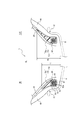
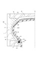
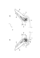
- FIGS. 1 to 3 are drawings for explaining a pneumatic tire according to the present embodiment and a method of manufacturing the pneumatic tire.
- FIG. 1 is a cross-sectional view in the tire width direction showing a pneumatic tire 1 according to the present embodiment.
- FIG. 2 is an enlarged view of the vicinity of the bead portion 12 of the pneumatic tire 1 in FIG. In FIG. 1 and FIG. 2, for convenience, the rim R on which the tire 1 is assembled is shown by a broken line.
- rim is an industrial standard effective for a region where a tire is produced and used, in Japan JATMA (Japan Automobile Tire Association) JATMA YEAR BOOK, in Europe ETRTO (The European Tire STANDARDS MANUAL at STANDARDS MANUAL in the US and YEAR BOOK etc.
- the internal structure of the pneumatic tire 1 of the present embodiment is asymmetric with respect to the tire equatorial plane CL. It is preferable that the pneumatic tire 1 has a specified mounting direction with respect to the vehicle, but the mounting direction with respect to the vehicle may not be specified.
- the “pneumatic tire” and the “unvulcanized tire” described later are also referred to simply as the “tire”.
- the mounting direction of the tire 1 with respect to the vehicle is designated.
- the tire 1 of the present embodiment includes a tread portion 10, a pair of sidewall portions 11 extending inward in the tire radial direction from both end portions of the tread portion 10 in the tire width direction, and sidewall portions 11. It is comprised from a pair of bead part 12 which follows the tire radial direction inner side, respectively.
- the tire 1 includes a rubber 40, a bead filler 70, a bead core 60 located on the inner side in the tire radial direction of the bead filler 70, a carcass 20, and a belt 30.
- the bead core 60 and the bead filler 70 are embedded in the rubber 40.
- the bead core 60 and the bead filler 70 constitute a core / filler member 50 configured integrally.
- the bead core 60 and the bead filler 70 may be separate.
- a carcass 20 including at least one layer (one layer in the illustrated example) of carcass plies extends in a toroidal shape between a pair of bead cores 60 located on both sides with respect to the tire equatorial plane CL. ing.
- the carcass ply of the carcass 20 has, for example, a structure in which a cord made of steel or organic fiber is coated with rubber.
- the carcass 20 extends from the pair of bead cores 60 in a toroidal shape from the innermost end of the main body portion 20a in the tire radial direction at each of both sides with respect to the tire equatorial plane CL. And a pair of folded back portions 20b folded back toward the tire width direction.
- a belt 30 composed of at least one layer (three layers in the example of the drawing) is disposed on the tire radial direction outer side of the crown area of the carcass 20 of the tread portion 10.
- the tire 1 of the present embodiment is not limited to the example of FIG. 1, and the configuration of other portions is optional as long as at least the bead filler 70 disposed in the bead portion 12 and the rubber 40 are provided. It is good.
- one of the tire width direction one side (in the example of the figure, the vehicle attachment inner side) with respect to the tire equatorial plane CL may be referred to as "bead filler 70o".
- a pair of bead fillers 70 located on the both sides with respect to the tire equatorial plane CL are mutually comprised asymmetrical with respect to the tire equatorial plane CL.
- Each of these bead fillers 70 is made of a resin material.
- “being configured to be asymmetrical to each other with respect to the tire equatorial plane CL” means that the bead fillers 70i on one side in the tire width direction are reversed to the other side in the tire lateral direction Refers to the configuration not being completely identical to the configuration of the bead filler 70 o on the other side in the tire width direction, and the configuration being at least partially different.
- configuration refers to the configuration when the shape and the material (resin material) are viewed together.
- the shapes of the pair of bead fillers 70 may be asymmetric with respect to the tire equatorial plane CL.
- the materials (resin materials) constituting the pair of bead fillers 70 may be different from each other. In determining whether or not the "shapes" match, it is judged three-dimensionally including the dimensions, and for example, when similar but not congruent, it is determined that "the shapes are different".
- the bead filler 70 In determining whether or not the "materials" match, not only the main components are compared, but also including the composition, mass, density, physical properties, etc., and it is temporarily assumed that the bead filler 70 is different in constituent material When it comprises from a plurality of parts, it shall judge including the shape of each part in bead filler 70, a position, and material. In the example of FIG. 1 and FIG. 2, as will be described later, the shapes of the pair of bead fillers 70 are mutually asymmetric with respect to the tire equatorial plane CL.
- the bead filler 70 is made of the same resin material as the covering layer 65 integrally with the covering layer 65 of the bead core 60.
- the resin material constituting the bead filler 70 may be different from the covering layer 65 of the bead core 60.
- the resin material constituting the bead filler 70 may be different for each part of the bead filler 70.
- the bead wire bundle 62 of the bead core 60 merely indicates a configuration in which a plurality of cross sections of the bead wire 62 a constituting the bead core 60 appear when the cross section in the tire width direction is viewed.
- the actual number of bead wires 62a may be one or more. That is, the bead wire bundle 62 may be configured by winding a single bead wire 62a a plurality of times in the tire circumferential direction, or a plurality of bead wires 62a may be respectively wound once or a plurality in the tire circumferential direction. It may be configured by being wound round.
- any known material can be used as the bead wire 62a, and for example, a steel cord can be used.
- the steel cord can be made of, for example, a monofilament of steel or a stranded wire.
- organic fibers, carbon fibers and the like can also be used.
- the covering layer 65 of the bead core 60 extends continuously along the circumferential direction of the tire, and the bead wire bundle 62 of the bead core 60 is viewed when the cross section in the tire width direction is viewed in at least a part of the circumferential direction.
- the ring is configured to surround the entire circumference.
- the covering layer 65 may not be annular when looking at a cross section in the tire width direction in a part of the tire circumferential direction, and may be, for example, C-shaped.
- each bead wire 62a is coated with a coating resin 63 made of a resin material inside the annular shape of the coating layer 65.
- the gap area between the coating layer 65 and each bead wire 62 a is filled with the coating resin 63.
- the resin material forming the covering resin 63 is different from the resin material forming the covering layer 65.
- the resin material constituting the covering resin 63 may be the same as the resin material constituting the covering layer 65.
- the present invention is not limited to this example, and each bead wire 62a may be covered with a covering rubber made of rubber instead of the covering resin 63 inside the annular shape of the covering layer 65 when the cross section in the tire width direction is viewed. Good.
- the gap area between the coating layer 65 and each bead wire 62a may be filled with the coating rubber.
- the covering layer 65 may be made of rubber, and the covering layer 65 may be omitted.
- the “resin material” constituting the bead filler 70, the coating layer 65, the coating resin 63 and the like refers to a material different from rubber (an organic polymer substance exhibiting rubber elasticity at normal temperature).
- the “resin material” is capable of maintaining almost (preferably complete) shape without softening (preferably at all) even at high temperatures used in the vulcanization process.
- the “resin material” is much harder (for example, one hundred times to several hundreds times) harder than the rubber 40 constituting the tire 1 at normal temperature and lighter than the rubber 40 constituting the tire 1.
- thermoplastic elastomer for example, a thermoplastic elastomer or a thermoplastic resin can be used, and a resin in which crosslinking occurs due to heat or electron beam, or a resin that cures due to thermal dislocation can also be used.
- resin material for example, a thermoplastic elastomer or a thermoplastic resin can be used, and a resin in which crosslinking occurs due to heat or electron beam, or a resin that cures due to thermal dislocation can also be used.
- thermoplastic elastomers it is desirable to use thermoplastic elastomers in view of the required elasticity when traveling.
- thermoplastic elastomers polyolefin-based thermoplastic elastomer (TPO), polystyrene-based thermoplastic elastomer (TPS), polyamide-based thermoplastic elastomer (TPA), polyurethane-based thermoplastic elastomer (TPU), polyester-based thermoplastic elastomer (TPC) And dynamically cross-linked thermoplastic elastomer (TPV).
- the thermoplastic resin may, for example, be a polyurethane resin, a polyolefin resin, a vinyl chloride resin or a polyamide resin.
- the deflection temperature under load (at 0.45 MPa load) specified in ISO 75-2 or ASTM D 648 is 78 ° C. or higher
- the tensile yield strength specified in JIS K7113 is 10 MPa or higher
- those having a tensile elongation at break (JIS K7113) defined in JIS K7113 of 50% or more can also be used.
- the tensile elastic modulus (defined in JIS K7113: 1995) of the “resin material” is preferably 50 MPa or more, and preferably 1000 MPa or less.
- the softening point of the “resin material” is preferably higher than a predetermined vulcanization temperature used in the vulcanization step.
- the method of manufacturing the pneumatic tire according to the present embodiment includes a vulcanization step of vulcanizing the unvulcanized tire 1 ′ in the vulcanizing mold 200.
- the unvulcanized tire 1 ′ is manufactured in the unvulcanized tire manufacturing process before the vulcanizing process.
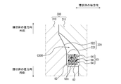
- FIG. 3 is a view for explaining a method of manufacturing a pneumatic tire according to the present embodiment.
- the method of manufacturing the pneumatic tire according to the present embodiment includes a vulcanization step of vulcanizing the unvulcanized tire 1 ′ in the vulcanizing mold 200.
- the unvulcanized tire 1 ′ is manufactured in the unvulcanized tire manufacturing process before the vulcanizing process.
- FIG. 3 the state in which the unvulcanized tire is accommodated in the vulcanized mold in the vulcanization step is shown by the tire width direction cross-section of the half of the tire.
- unvulcanized tire 1 'in the vulcanization process shown in FIG. 3 becomes tire 1 shown in FIG. 1 after the vulcanization process.
- the unvulcanized tire is manufactured by assembling the bead filler 70 manufactured in the bead filler manufacturing process for manufacturing the bead filler 70 and the bead filler manufacturing process with other tire constituent members And 1) (FIG. 3).
- the core filler member 50 is manufactured by integrally molding the bead filler 70 and the bead core 60.
- the bead filler manufacturing step only the bead filler 70 may be manufactured.
- the bead core 60 may be separately manufactured by a bead core manufacturing process. The method of manufacturing the core filler member 50 will be described in more detail later with reference to FIGS. 7A and 7B.
- the bead filler 70 (in this example, the core / filler member 50) manufactured in the bead filler manufacturing process, the unvulcanized rubber 40 ', and other tire constituent members (in this example, the carcass ply 20, the belt 30) And so on), for example, on a forming drum (not shown) and molded to obtain an unvulcanized tire 1 '.
- a cylindrical tire case (not shown) consisting of a part or all of the tire components is expanded by the bladder 230.
- unvulcanized tire 1 'obtained by the assembly molding process is a pair of sidewall portions extending inward in the tire radial direction from both ends of the tread portion 10' and the tread portion 10 'in the tire width direction. 11 'and a pair of bead portions 12' continuous from the sidewall portion 11 'to the inner side in the tire radial direction, respectively.
- the tread portion 10 ′, the sidewall portion 11 ′ and the bead portion 12 ′ of the unvulcanized tire 1 ′ are, respectively, the tread portion 10 and the sidewall portions of the vulcanized tire 1 (FIG. 1) after the vulcanization process. 11, become the bead portion 12.
- a pair of bead fillers 70 positioned on both sides of the tire equatorial plane CL in the unvulcanized tire 1 ′ are made of resin materials, and the tire equatorial plane CL Are constructed asymmetrically with respect to each other.
- the meaning of "being configured to be asymmetrical with respect to the tire equatorial plane CL" is as described above.
- the bead core 60 and the bead filler 70 are embedded in the unvulcanized rubber 40 '.
- the bead core 60 and the bead filler 70 constitute the core / filler member 50 configured integrally.
- the bead core 60 and the bead filler 70 may be separate.
- the unvulcanized tire 1 ′ obtained by the assembly and molding process is vulcanized in the vulcanizing mold 200.
- the inner surface of the vulcanizing mold 200 forms a tire outer surface molding surface 220 configured to mold the outer surface of the tire 1.
- the vulcanizing mold 200 is provided with a plurality of vulcanizing mold parts 210, 211, 212, and the inner surfaces of the respective vulcanizing mold parts 210, 211, 212 are respectively the tire outer surface It constitutes a part of the molding surface 220.
- the vulcanizing mold 200 comprises a tread vulcanizing mold portion 210 configured to mold the outer surface of the tread portion 10 of the tire 1, and the sidewall portion 11 and the bead portion 12 of the tire 1.
- a side-vulcanized mold portion 211 configured to mold a portion of the outer surface
- a bead-cured mold portion 212 configured to mold the outer surface of the remaining portion of the bead portion 12 of the tire 1.
- the invention is not limited to the example shown in the drawings, and the vulcanizing mold 200 may be composed of any of a plurality of vulcanizing mold parts. In a state where the vulcanized mold portions 210, 211, 212 are closed, the tire outer surface molding surface 220 defines a cavity C200.
- the unvulcanized tire 1 ′ is disposed in the cavity C 200 of the vulcanized mold 200 and is a bladder disposed on the tire inner cavity side of the unvulcanized tire 1 ′. It is vulcanized and molded at a predetermined temperature while being pressed against the tire outer surface molding surface 220 by 230.
- the tire components in this example, the bead filler 70 and the coating layer 65 of the bead core 60 and the coating resin 63
- the tire components made of resin material soften (preferably completely) and thus deform and move. Without (almost completely) shape and position is maintained.
- the bead filler 70 is composed of a plurality of parts having different constituent materials, it is possible to suppress the change in the material configuration and the shape of the bead filler 70 because the parts are mixed with each other.
- the unvulcanized rubber 40 ′ flows in the cavity C 200 during the vulcanization process, and is then vulcanized while the outer surface of the tire is formed by the outer surface forming surface 220. After the vulcanization process, a vulcanized pneumatic tire 1 (FIGS. 1 and 2) is obtained.
- the pair of bead fillers 70 are configured to be asymmetrical to each other with respect to the tire equatorial plane CL, the respective configurations of the respective tire half portions can be made different. The tire performance can be improved as compared with the case where the configuration of each tire half is the same.
- the tire 1 when the tire 1 is attached with the vehicle 1 in the specified direction as in this example, the tire 1 can be obtained, for example, at the time of cornering, between the tire half inside the vehicle and the tire half outside the vehicle
- the configuration of the bead filler 70i on the inside of the vehicle and the bead filler 70o on the outside of the vehicle in consideration of the difference in performance, physical properties, etc., the performance of the entire tire can be greatly improved.
- the pair of bead fillers 70 is made of a resin material, the bead fillers 70 are softened to change their shape even under high temperature used in the vulcanization process at the time of tire manufacture.
- the bead filler 70 is composed of a plurality of parts having different constituent materials, it is possible to significantly suppress the change in the material configuration and the shape of the bead filler 70 due to mixing of the respective parts.
- the configuration of the bead filler 70 can be maintained constant before and after the vulcanization process. For this reason, it is possible to obtain the desired asymmetric configuration of the bead filler in the manufactured tire, and to obtain the expected tire performance as the effect of the asymmetric configuration of the bead filler, more reliably than ever before.
- the bead filler 70 is made of rubber, the rubber (the shape, etc.) of the bead filler obtained after the vulcanization process is limited because the rubber constituting the bead filler flows during the vulcanization process.
- the bead filler 70 is made of a resin material, the bead filler 70 can be configured in a special shape that is not possible with, for example, rubber. Thus, the design freedom of the bead filler 70 can be greatly expanded.
- the bead filler 70 is made of a resin material which is much harder and less likely to deteriorate than rubber, it can be obtained after manufacture as compared to, for example, the bead filler 70 made of rubber.
- the collapse of the shape of the bead filler 70 due to the long-term use of the tire 1 can also be significantly suppressed.
- the desired bead filler configuration can be obtained in each tire half, and in turn, the desired tire performance can be obtained.
- the bead filler 70 can be miniaturized while maintaining the durability of the bead filler 70 equal to that of the conventional one.
- the bead filler 70 is made of a resin material lighter than rubber, for example, the weight reduction of the tire 1 and thus the low rolling resistance can be achieved compared to the case where the bead filler 70 is made of rubber. And fuel consumption can be achieved.
- the coating layer 65 surrounding the bead wire bundle 62 of the bead core 60 is made of a resin material which hardly softens in the vulcanization step, for example, the bead core 60 contains a resin material.
- the bead core 60 contains a resin material.
- the coating layer 65 of the bead core 60 is made of a resin material much harder than rubber, for example, the bead core 60 does not contain a resin material.
- the deformation of the bead core 60 due to the carcass 20 being pulled outward in the tire radial direction by the action of the bladder 230 at the time of manufacture can be significantly suppressed.
- the collapse of the shape of the bead core 60 by using the tire 1 obtained after manufacture for a long period of time can also be suppressed significantly.
- the fit between the bead portion 12 of the tire 1 and the rim R can be maintained high, and the exercise performance and the water tightness of the tire can be maintained well.
- the coating layer 65 of the bead core 60 is made of a resin material, the bead filler 70 can be configured integrally with the coating layer 65. Thereby, the rigidity and durability of the bead portion 12 can be improved.
- the bead core 60 and the manufacturing process of the bead filler 70 can be It can be treated as a part, and manufacturability can be improved.
- a part of the bead core 60 is made of a resin material lighter than rubber, for example, the bead core 60 does not contain a resin material, and the bead wire bundle 62 is made of rubber only. As a result, the tire 1 can be reduced in weight as well as reduced in rolling resistance and fuel consumption as compared with the case of being covered by the above.
- each bead wire 62a is coated with the coating resin 63 inside the coating layer 65 of the bead core 60, for example, each bead wire 62a is coated rubber inside the coating layer 65 of the bead core 60
- the shape of the bead core 60 and thus the shape of the bead filler 70 adjacent thereto can be more reliably maintained during manufacture and use, and the durability of the bead core 60 and the bead filler 70 can be further improved.
- the weight and size of the tire 1 can be further reduced.
- the shapes of the pair of bead fillers 70 are asymmetrical with respect to the tire equatorial plane CL.
- the materials of the pair of bead fillers 70 are the same as one another, but may be different from one another. More specifically, in this example, the tire radial direction height Ho of the bead filler 70o on the vehicle mounting outer side with respect to the tire equatorial plane CL, and the tire radial direction height of the bead filler 70i on the vehicle mounting inner side with respect to the tire equatorial plane CL. Higher than Hi (ie Ho> Hi).
- the tire radial direction heights Ho and Hi of the bead fillers 70o and 70i are, as shown in FIG. 2, from the innermost end in the tire radial direction of the tire 1, the outermost end in the tire radial direction of the bead fillers 70o and 70i The distance in the radial direction of the tire. And, since the bead fillers 70o and 70i are each made of a resin material, the tire radial direction heights Ho and Hi of the bead fillers 70o and 70i in the manufactured tire 1 are in the tire radial direction in the unvulcanized tire 1 ′. It is possible to significantly suppress the change from the height Ho and Hi, and to be as intended.
- the tire radial direction height Hi of the bead filler 70i on the inside of the vehicle mounted relatively low in the vulcanized tire 1, when the ground contact load is input, the tire radial direction from the bead filler 70i on the vehicle inside The free deformation of the carcass 20 on the outer side is facilitated, and thus the ride of the tire 1 can be softened. As described above, the ride comfort performance and the steering stability performance can be better achieved.
- the tire radial direction height Ho, Hi of the bead fillers 70o and 70i is a state in which the tire 1 is assembled to the rim R and the tire 1 filled with a predetermined internal pressure is unloaded. And shall be measured.
- predetermined internal pressure refers to the air pressure (maximum air pressure) corresponding to the maximum load capacity of a single wheel in application size and ply rating described in the aforementioned JATMA YEAR BOOK etc. In the case of the size not described, it means the air pressure (maximum air pressure) corresponding to the maximum load capacity specified for each vehicle on which the tire is mounted. In addition, it is also possible to substitute air here called inert gas other than nitrogen gas etc., and others.
- FIG. 4 shows a tire 1 according to a first modified example of the present invention, and is a view corresponding to FIG.
- the configuration of the pair of bead fillers 70 in the unvulcanized tire 1 'according to the first modification is the same as the configuration of the pair of bead fillers 70 in the tire 1 shown in FIG.
- the shapes of the pair of bead fillers 70 are mutually asymmetric with respect to the tire equatorial plane CL.
- the materials of the pair of bead fillers 70 are the same as one another, but may be different from one another.
- each of a pair of bead fillers 70o and 70i opens toward the vehicle installation inner side in the surface of each vehicle installation. It has the recessed parts 71o and 71i which were dug-out. These recessed portions 71o and 71i are positioned in the tire radial direction so as to overlap with the tire radial direction outermost end of the rim flange Rf when the tire 1 is assembled to the rim R, as shown in FIG. And is preferred. That is, in FIG.
- the recess 71i in the bead filler 70i on the vehicle mounting inner side is on the rim flange Rf side in the bead filler 70i
- the recess 71o in the bead filler 70o on the vehicle mounting outer side is the rim flange Rf in the bead filler 70o It is on the other side.
- the bead fillers 70o and 70i are respectively made of a resin material, the shapes of the recesses 71o and 71i of the bead fillers 70o and 70i in the manufactured tire 1 are the same as those of the recesses 71o and 71i in the unvulcanized tire 1 ′. It is possible to significantly suppress the change from the shape, and to be as intended.
- the bead filler 70o on the vehicle attachment outer side is The movement of the meat portion is easily restrained by the rim flange Rf, so that the load supporting performance of the tire half on the vehicle mounting outer side can be improved, and the steering stability of the tire 1 can be improved.
- the bead fillers 70o and 70i have the shapes when assuming that the recesses 71o and 71i are filled with the resin material, that is, the vehicle attachment inner surfaces of the bead fillers 70o and 70i are the recesses 71o,
- the shapes when smoothly connected along the opening surface to the inside of the vehicle mounting of 71 i are symmetrical to each other with respect to the tire equatorial plane CL.
- FIG. 5 shows a tire 1 according to a second modified example of the present invention, and is a view corresponding to FIG.
- the configuration of the pair of bead fillers 70 in the unvulcanized tire 1 ′ according to the second modification is the same as the configuration of the pair of bead fillers 70 in the tire 1 shown in FIG.
- resin materials constituting the pair of bead fillers 70 are different from each other.
- the shapes of the pair of bead fillers 70 are symmetrical to each other with respect to the tire equatorial plane CL, but may be asymmetric to each other.
- the resin material that constitutes the bead filler 70o on the vehicle mounting outer side with respect to the tire equatorial plane CL is the resin that constitutes the bead filler 70i on the vehicle mounting inner side with respect to the tire equatorial plane CL.
- the material has a higher tensile or flexural modulus than the material.
- the “tensile modulus of elasticity” of the resin material is to be measured in accordance with JIS K7113: 1995
- the “bending elastic modulus” is to be measured in accordance with JIS K7171: 2016.
- the bead fillers 70o and 70i are each made of a resin material, the shape of the bead fillers 70o and 70i in the manufactured tire 1 changes from the shape of the bead fillers 70o and 70i in the unvulcanized tire 1 ′. Can be greatly suppressed, and each can be as expected.
- the ground contact load is input to the vulcanized tire 1 by relatively increasing the tensile elastic modulus or bending elastic modulus of the resin material of the bead filler 70o on the vehicle mounting outer side, the tire half on the vehicle mounting outer side The deformation can be effectively suppressed and, in turn, the steering stability of the tire 1 can be improved.
- FIG. 6 shows a tire 1 according to a third modification of the present invention, and is a view corresponding to FIG.
- the configuration of the pair of bead fillers 70 in the unvulcanized tire 1 ′ according to the third modification is the same as the configuration of the pair of bead fillers 70 in the tire 1 shown in FIG.
- resin materials constituting the pair of bead fillers 70 are different from each other.
- the shapes of the pair of bead fillers 70 are symmetrical to each other with respect to the tire equatorial plane CL, but may be asymmetric to each other.
- the bead filler 70o on the vehicle mounting outer side with respect to the tire equatorial plane CL is composed of the tire radial direction inner portion 72o and the tire radial direction outer portion 73o which are different in constituent material.
- the bead filler 70i on the vehicle mounting inner side with respect to the tire equatorial plane CL includes the tire radial direction inner portion 72i and the tire radial direction outer portion 73i which are different in constituent material from each other.
- the materials are the same but the shape is asymmetric with respect to the tire equatorial plane CL is there.
- the resin material constituting the tire radial direction inner portions 72o and 72i of the bead fillers 70o and 70i has a tensile elastic modulus or a bending elastic modulus than the resin material constituting the tire radial direction outer portions 73o and 73i of the bead fillers 70o and 70i. Is high.
- the ratio of the area of the tire radial inner portion 72o to the area of the bead filler 70o on the vehicle mounting outer side is the area of the tire radial inner portion 72i to the area of the bead filler 70i on the vehicle mounting inner Higher than the percentage of And, since the bead fillers 70o and 70i are each made of a resin material, the entire shape of the bead fillers 70o and 70i in the manufactured tire 1 and the shape of each portion 72o, 73o, 72i and 73i are not yet It is possible to significantly suppress the change from their shape in the vulcanized tire 1 and to be as intended.
- the deformation of the tire half on the outer side of the vehicle can be effectively suppressed, and as a result, the steering stability performance of the tire 1 is improved. it can.
- the vulcanized tire 1 when the ground contact load is input, free deformation of the tire half on the inner side of the vehicle mounting is facilitated, and the ride comfort of the tire 1 can be softened. As a result, both the ride comfort performance and the steering stability performance can be better achieved.
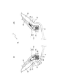
- FIGS. 7A and 7B an example of a method for manufacturing the bead core 60 and the bead filler 70 will be described in detail with reference to FIGS. 7A and 7B.
- the method of manufacturing the bead core 60 and the bead filler 70 in this example is to manufacture the core filler member 50 shown in FIG.
- the bead core 60 and the bead filler 70 may be manufactured by a method different from this example.
- the method of manufacturing the core / filler member 50 of the present example includes an annular body forming step, an injection molding step, and a cooling step.
- FIG. 7A shows the state of the injection molding process
- FIG. 7B shows the core filler member 50 obtained by the bead core manufacturing process.
- the annular member 61 is formed by winding a strip member 64 formed by coating one or more bead wires 62a with the covering resin 63.
- An annular body 61 shown in FIG. 7A is formed by, for example, spirally winding a strip member 64 formed by covering one or more (three in the illustrated example) bead wires 62a with a covering resin 63.
- the strip member 64 having a substantially rectangular shape in an axial cross section is stacked in three stages in the radial direction of the annular body 61.
- the axial direction of the annular body 61 refers to a direction parallel to the central axis of the substantially annular shape (spiral shape) of the annular body 61.
- the number of bead wires 62a may be one or more without being particularly limited in this case.
- the covering member 63 in a molten state is coated on the outer peripheral side of the bead wire 62a and solidified by cooling to form the strip member 64.
- the cross-sectional shape of the strip member 64 is substantially rectangular in this example, but is not limited to this example, for example, various shapes such as a substantially parallelogram can do.
- the cross-sectional shape of the strip member 64 can be formed into a desired shape using, for example, an extruder.
- the annular body 61 can be formed by winding and stacking the strip members 64.
- the strip member 64 is wound while melting the covering resin 63 by hot plate welding or the like. It can be performed by turning and solidifying the molten coating resin 63. Alternatively, bonding can be performed by bonding the steps with an adhesive or the like.
- the annular body 61 formed in the annular body forming step is covered with a resin material to form the covering layer 65 and the bead filler 70 integral with the covering layer 65 .
- the annular body 61 formed in the annular body forming step is disposed in the cavity C300 of the injection molding die 300, and the injection resin heated and melted is a gate (shown in FIG. Injection into the cavity C300.
- the annular body 61 may be fixed at a predetermined position in the cavity C300 by a jig not shown.
- the injection mold 300 is devoid of a molding surface 320 whose inner surface is configured to mold the outer surface of the core filler member 50. More specifically, the injection mold 300 includes a plurality of injection mold parts 310 and 311, and the inner surface of each injection mold part 310 and 311 has a part of the molding surface 320, respectively. Configured.
- the molding surface 320 of the injection molding die 300 is a cover molding surface 321 configured to mold the outer surface of the coating layer 65 of the bead core 60 and a filler molding configured to mold the outer surface of the bead filler 70. And a surface 322.
- the coating layer 65 and the bead filler 70 are solidified by cooling.
- the completed core / filler member 50 is removed from the injection mold 300.
- the bead core 60 in the core filler member 50 becomes a structure by which the cyclic
- a bead filler 70 is integrally formed with the coating layer 65 on the radially outer side of the coating layer 65.
- the stacked annular bodies 61 receive the force of thermal contraction by the covering layer 65 injected to the periphery in the cooling step. Thereby, the annular body 61 can be tightened by the surrounding cover layer 65.
- the bead core 60 has a configuration in which the periphery of the annular body 61 is covered with the solidified covering layer 65. For this reason, in addition to the fact that the surrounding solidified coating layer 65 can protect the annular body 61 against external force such as lateral force of the tire, the shape of the annular body 61 is tightened by the surrounding solidified coating layer 65 Can be suppressed. Thus, a highly durable bead core 60 can be obtained.
- the bead filler 70 is molded together with the covering layer 65, there is no need to separately provide the manufacturing process of the bead core 60 and the manufacturing process of the bead filler 70.
- the bead core 60 and the bead filler 70 can be treated as one part, and the productivity can be improved.
- the bead filler 70 may be manufactured by injection molding, and may be adhered to the covering layer 65 of the bead core 60 by welding or an adhesive.
- the covering layer 65 is preferably made of the same resin material as the covering resin 63. This is because the covering layer 65 and the covering resin 63 can be easily welded or adhered.
- the covering layer 65 is preferably made of a resin material different from the covering resin 63.
- the “resin material” in the present specification is harder than the rubber 40. Therefore, in order to reduce the difference in rigidity between the bead core 60 and the surrounding rubber 40, it is preferable that the covering layer 65 directly adjacent to the rubber 40 has a hardness smaller than that of the covering resin 63 (close to the hardness of the rubber 40).
- the coating layer 65 preferably has a hardness greater than that of the coating resin 63.
- the covering layer 65 it is preferable to use a resin material having high adhesion to the rubber 40.
- the pneumatic tire according to the present invention and the method of manufacturing a pneumatic tire can be used for any type of pneumatic tire, such as a pneumatic tire for passenger cars.
- non-vulcanized tire (tire) 1: pneumatic tire (tire) 10', 10: tread portion 11 '11: sidewall portion 12' 12: bead portion 20: carcass 20a
Landscapes
- Engineering & Computer Science (AREA)
- Mechanical Engineering (AREA)
- Tires In General (AREA)
- Tyre Moulding (AREA)
Abstract
空気入りタイヤは、タイヤ赤道面に対して両側に位置する一対のビードフィラは、それぞれ樹脂材料から構成されているとともに、タイヤ赤道面に対して互いに非対称に構成されている。
Description
この発明は、空気入りタイヤ、及び、空気入りタイヤの製造方法に関するものである。
本願は、2017年6月19日に、日本に出願された特願2017-119978号に基づく優先権を主張するものであり、その内容の全文をここに援用する。
本願は、2017年6月19日に、日本に出願された特願2017-119978号に基づく優先権を主張するものであり、その内容の全文をここに援用する。
従来、タイヤ赤道面に対して両側に位置する一対のゴム製のビードフィラが、タイヤ赤道面に対して互いに非対称に構成された、空気入りタイヤが提案されている(例えば、特許文献1)。ビードフィラをタイヤ赤道面に対して非対称に構成することにより、タイヤ性能を向上できることが期待されている。
しかしながら、上述の空気入りタイヤにおいては、タイヤ製造時における加硫工程の間にビードフィラを構成するゴムが周りのゴムとともに流動する結果、加硫工程の前後でビードフィラの構成(形状等)が異なるおそれがあった。このため、製造後のタイヤにおいて、所期したビードフィラの非対称構成が得られず、ひいては、ビードフィラの非対称構成による効果として所期したタイヤ性能が得られないおそれがあった。また、加硫工程の間にビードフィラを構成するゴムが流動することから、加硫工程後に得られるビードフィラの構成(形状等)には限りがあり、ひいては、ビードフィラの設計自由度が十分でなかった。
この発明は、上述した課題を解決するためのものであり、タイヤ製造時の加硫工程におけるビードフィラの構成の変化を抑制でき、所期したビードフィラの非対称構成を得ることができる、空気入りタイヤ、及び、空気入りタイヤの製造方法、を提供することを目的とするものである。
この発明の空気入りタイヤは、タイヤ赤道面に対して両側に位置する一対のビードフィラが、それぞれ、樹脂材料から構成されているとともに、前記タイヤ赤道面に対して互いに非対称に構成されている。
この発明の空気入りタイヤの製造方法は、未加硫タイヤを加硫金型内で加硫する加硫工程を含む、空気入りタイヤの製造方法であって、前記未加硫タイヤにおける、タイヤ赤道面に対して両側に位置する一対のビードフィラが、それぞれ、樹脂材料から構成されているとともに、前記タイヤ赤道面に対して互いに非対称に構成されている。
この発明によれば、タイヤ製造時の加硫工程におけるビードフィラの構成の変化を抑制でき、所期したビードフィラの非対称構成を得ることができる、空気入りタイヤ、及び、空気入りタイヤの製造方法、を提供できる。
以下に、図面を参照しつつ、この発明に係る空気入りタイヤ、及び、空気入りタイヤの製造方法の実施形態を例示説明する。
本発明に係る空気入りタイヤ、及び、空気入りタイヤの製造方法は、例えば乗用車用空気入りタイヤ等、任意の種類の空気入りタイヤに利用できるものである。
本発明に係る空気入りタイヤ、及び、空気入りタイヤの製造方法は、例えば乗用車用空気入りタイヤ等、任意の種類の空気入りタイヤに利用できるものである。
図1~図3は、本実施形態に係る空気入りタイヤ、及び、空気入りタイヤの製造方法を説明するための図面である。
図1は、本実施形態に係る空気入りタイヤ1を示す、タイヤ幅方向断面図である。図2は、図1のうち、空気入りタイヤ1のビード部12の近傍を拡大した図である。図1及び図2には、便宜のため、タイヤ1が組み付けられるリムRを、破線により示している。
図1は、本実施形態に係る空気入りタイヤ1を示す、タイヤ幅方向断面図である。図2は、図1のうち、空気入りタイヤ1のビード部12の近傍を拡大した図である。図1及び図2には、便宜のため、タイヤ1が組み付けられるリムRを、破線により示している。
本明細書において、「リム」とは、タイヤが生産され、使用される地域に有効な産業規格であって、日本ではJATMA(日本自動車タイヤ協会)のJATMA YEAR BOOK、欧州ではETRTO (The European Tyre and Rim Technical Organisation)のSTANDARDS MANUAL、米国ではTRA (The Tire and Rim Association, Inc.)のYEAR BOOK等に記載されているまたは将来的に記載される、適用サイズにおける標準リム(ETRTOのSTANDARDS MANUALではMeasuring Rim、TRAのYEAR BOOKではDesign Rim)を指す(すなわち、上記の「リム」には、現行サイズに加えて将来的に上記産業規格に含まれ得るサイズも含む。「将来的に記載されるサイズ」の例としては、ETRTOのSTANDARDS MANUAL 2013年度版において「FUTURE DEVELOPMENTS」として記載されているサイズを挙げることができる。)が、上記産業規格に記載のないサイズの場合は、タイヤのビード幅に対応した幅のリムをいう。
本実施形態の空気入りタイヤ1は、その内部構造が、タイヤ赤道面CLに対して非対称に構成されている。この空気入りタイヤ1は、車両に対する装着方向が指定されたものであると、好適であるが、車両に対する装着方向が指定されていなくてもよい。
本明細書では、「空気入りタイヤ」や後述の「未加硫タイヤ」を、単に「タイヤ」ともいう。
本例において、タイヤ1は、車両に対する装着方向が指定されている。各図において、「OUT」とは、タイヤ1を車両に装着した際のタイヤ赤道面CLに対する車両幅方向外側(車両装着外側)を示し、「IN」とは、タイヤ1を車両に装着した際のタイヤ赤道面CLに対する車両幅方向内側(車両装着内側)を示す。
本明細書では、「空気入りタイヤ」や後述の「未加硫タイヤ」を、単に「タイヤ」ともいう。
本例において、タイヤ1は、車両に対する装着方向が指定されている。各図において、「OUT」とは、タイヤ1を車両に装着した際のタイヤ赤道面CLに対する車両幅方向外側(車両装着外側)を示し、「IN」とは、タイヤ1を車両に装着した際のタイヤ赤道面CLに対する車両幅方向内側(車両装着内側)を示す。
本実施形態のタイヤ1は、図1に示すように、トレッド部10と、トレッド部10のタイヤ幅方向両端部からそれぞれタイヤ径方向内側へ延びる一対のサイドウォール部11と、サイドウォール部11からそれぞれタイヤ径方向内側に連続する一対のビード部12と、から構成されている。
図1の例において、タイヤ1は、ゴム40と、ビードフィラ70と、ビードフィラ70のタイヤ径方向内側に位置するビードコア60と、カーカス20と、ベルト30とを備えている。
タイヤ1のビード部12では、ビードコア60及びビードフィラ70が、ゴム40内に埋設されている。本例において、ビードコア60とビードフィラ70とは、一体に構成されたコア・フィラ部材50を構成している。ただし、ビードコア60とビードフィラ70とは別体でもよい。
図1の例において、タイヤ赤道面CLに対して両側に位置する一対のビードコア60どうしの間には、少なくとも一層(図の例では1層)のカーカスプライを含むカーカス20が、トロイド状に延びている。カーカス20のカーカスプライは、例えば、スチール製又は有機繊維製等のコードがゴムにより被覆された構成を有する。図の例において、カーカス20は、一対のビードコア60どうしの間をトロイド状に延びる本体部20aと、タイヤ赤道面CLに対する両側のそれぞれにおいて、本体部20aのタイヤ径方向最内端から、ビードコア60の周りでタイヤ幅方向外側に向けて折り返された、一対の折り返し部20bと、を含んでいる。トレッド部10の、カーカス20のクラウン域よりもタイヤ径方向外側には、少なくとも一層(図の例では3層)のベルト層からなるベルト30が配置されている。
ただし、本実施形態のタイヤ1は、図1の例のものに限られず、少なくとも、ビード部12に配置されたビードフィラ70と、ゴム40とを備えるものである限り、他の部分の構成は任意でよい。
タイヤ1のビード部12では、ビードコア60及びビードフィラ70が、ゴム40内に埋設されている。本例において、ビードコア60とビードフィラ70とは、一体に構成されたコア・フィラ部材50を構成している。ただし、ビードコア60とビードフィラ70とは別体でもよい。
図1の例において、タイヤ赤道面CLに対して両側に位置する一対のビードコア60どうしの間には、少なくとも一層(図の例では1層)のカーカスプライを含むカーカス20が、トロイド状に延びている。カーカス20のカーカスプライは、例えば、スチール製又は有機繊維製等のコードがゴムにより被覆された構成を有する。図の例において、カーカス20は、一対のビードコア60どうしの間をトロイド状に延びる本体部20aと、タイヤ赤道面CLに対する両側のそれぞれにおいて、本体部20aのタイヤ径方向最内端から、ビードコア60の周りでタイヤ幅方向外側に向けて折り返された、一対の折り返し部20bと、を含んでいる。トレッド部10の、カーカス20のクラウン域よりもタイヤ径方向外側には、少なくとも一層(図の例では3層)のベルト層からなるベルト30が配置されている。
ただし、本実施形態のタイヤ1は、図1の例のものに限られず、少なくとも、ビード部12に配置されたビードフィラ70と、ゴム40とを備えるものである限り、他の部分の構成は任意でよい。
本明細書では、タイヤ赤道面CLに対して両側に位置する一対のビードフィラ70のうち、タイヤ赤道面CLに対してタイヤ幅方向一方側(図の例では車両装着内側)のほうを「ビードフィラ70i」と表記し、タイヤ赤道面CLに対してタイヤ幅方向他方側(図の例では車両装着外側)のほうを「ビードフィラ70o」と表記することがある。
図1及び図2に示すように、タイヤ赤道面CLに対して両側に位置する一対のビードフィラ70は、タイヤ赤道面CLに対して互いに非対称に構成されている。これらのビードフィラ70は、それぞれ樹脂材料から構成されている。
これら一対のビードフィラ70について、「タイヤ赤道面CLに対して互いに非対称に構成されている」とは、タイヤ幅方向一方側のビードフィラ70iをタイヤ赤道面CLに対してタイヤ幅方向他方側に反転させたときの構成が、タイヤ幅方向他方側のビードフィラ70oの構成と、完全には一致せず、構成が少なくとも部分的に異なることを指す。ここでいう「構成」とは、形状及び材料(樹脂材料)を併せて観たときの構成を指している。
例えば、これら一対のビードフィラ70は、それぞれの形状が、タイヤ赤道面CLに対して互いに非対称であってもよい。また、これに加えて又は代えて、これら一対のビードフィラ70は、それぞれを構成する材料(樹脂材料)が、互いに異なっていてもよい。
「形状」が一致するか否かの判断においては、寸法も含めて3次元的に判断するものとし、例えば相似であるが合同でない場合は「形状が異なる」と判断する。「材料」が一致するか否かの判断においては、主成分のみを比較するのではなく、組成、質量、密度、物性等も含めて判断するものとし、また、仮にビードフィラ70が構成材料の異なる複数の部分から構成されている場合は、ビードフィラ70における各部分の形状、位置及び材料も含めて判断するものとする。
図1及び図2の例では、後述するように、一対のビードフィラ70の形状が、タイヤ赤道面CLに対して互いに非対称である。
これら一対のビードフィラ70について、「タイヤ赤道面CLに対して互いに非対称に構成されている」とは、タイヤ幅方向一方側のビードフィラ70iをタイヤ赤道面CLに対してタイヤ幅方向他方側に反転させたときの構成が、タイヤ幅方向他方側のビードフィラ70oの構成と、完全には一致せず、構成が少なくとも部分的に異なることを指す。ここでいう「構成」とは、形状及び材料(樹脂材料)を併せて観たときの構成を指している。
例えば、これら一対のビードフィラ70は、それぞれの形状が、タイヤ赤道面CLに対して互いに非対称であってもよい。また、これに加えて又は代えて、これら一対のビードフィラ70は、それぞれを構成する材料(樹脂材料)が、互いに異なっていてもよい。
「形状」が一致するか否かの判断においては、寸法も含めて3次元的に判断するものとし、例えば相似であるが合同でない場合は「形状が異なる」と判断する。「材料」が一致するか否かの判断においては、主成分のみを比較するのではなく、組成、質量、密度、物性等も含めて判断するものとし、また、仮にビードフィラ70が構成材料の異なる複数の部分から構成されている場合は、ビードフィラ70における各部分の形状、位置及び材料も含めて判断するものとする。
図1及び図2の例では、後述するように、一対のビードフィラ70の形状が、タイヤ赤道面CLに対して互いに非対称である。
図2に示すように、本例において、タイヤ赤道面CLに対して両側に位置する一対のビードコア60は、それぞれ、タイヤ幅方向断面を観たときに、ビードワイヤ束62と、ビードワイヤ束62の周囲を囲むとともに樹脂材料から構成された被覆層65と、を有している。
図1及び図2の例では、ビードフィラ70が、ビードコア60の被覆層65と一体に、被覆層65と同じ樹脂材料から構成されている。ただし、ビードフィラ70を構成する樹脂材料は、ビードコア60の被覆層65とは異なるものでもよい。また、ビードフィラ70を構成する樹脂材料は、ビードフィラ70の部分ごとに異なっていてもよい。
図2の例において、ビードコア60のビードワイヤ束62は、タイヤ幅方向断面を観たときに、ビードコア60を構成するビードワイヤ62aの断面が複数現れる構成を指しているにすぎず、ビードコア60を構成するビードワイヤ62aの実際の本数は、1本でも複数本でもよい。すなわち、ビードワイヤ束62は、1本のビードワイヤ62aがタイヤ周方向に複数回にわたって巻回されることによって構成されてもよいし、あるいは、複数本のビードワイヤ62aがそれぞれタイヤ周方向に1回又は複数回にわたって巻回されることによって構成されてもよい。
ビードワイヤ62aは、任意の既知の材料を用いることができ、例えばスチールコードを用いることができる。スチールコードは、例えば、スチールのモノフィラメント又は撚り線からなるものとすることができる。また、有機繊維やカーボン繊維等を用いることもできる。
ビードワイヤ62aは、任意の既知の材料を用いることができ、例えばスチールコードを用いることができる。スチールコードは、例えば、スチールのモノフィラメント又は撚り線からなるものとすることができる。また、有機繊維やカーボン繊維等を用いることもできる。
ビードコア60の被覆層65は、タイヤ周方向に沿って連続して延在しているとともに、タイヤ周方向の少なくとも一部において、タイヤ幅方向断面を観たときに、ビードコア60のビードワイヤ束62を全周にわたって囲むように、環状に構成されている。被覆層65は、タイヤ周方向の一部において、タイヤ幅方向断面を観たときに、環状でなくてもよく、例えばC字型等でもよい。
本例では、タイヤ幅方向断面を観たときに、被覆層65のなす環形状の内側で、各ビードワイヤ62aが、樹脂材料からなる被覆樹脂63によって被覆されている。いいかえれば、被覆層65と各ビードワイヤ62aとの間の隙間領域が、被覆樹脂63によって埋められている。
本例では、被覆樹脂63を構成する樹脂材料は、被覆層65を構成する樹脂材料とは異なる。ただし、被覆樹脂63を構成する樹脂材料は、被覆層65を構成する樹脂材料と同じでもよい。
本例に限られず、タイヤ幅方向断面を観たときに、被覆層65のなす環形状の内側で、各ビードワイヤ62aは、被覆樹脂63の代わりに、ゴムからなる被覆ゴムによって被覆されていてもよい。いいかえれば、被覆層65と各ビードワイヤ62aとの間の隙間領域が、被覆ゴムによって埋められていてもよい。
また、被覆層65はゴム製でもよく、また、被覆層65は無くてもよい。
本例では、タイヤ幅方向断面を観たときに、被覆層65のなす環形状の内側で、各ビードワイヤ62aが、樹脂材料からなる被覆樹脂63によって被覆されている。いいかえれば、被覆層65と各ビードワイヤ62aとの間の隙間領域が、被覆樹脂63によって埋められている。
本例では、被覆樹脂63を構成する樹脂材料は、被覆層65を構成する樹脂材料とは異なる。ただし、被覆樹脂63を構成する樹脂材料は、被覆層65を構成する樹脂材料と同じでもよい。
本例に限られず、タイヤ幅方向断面を観たときに、被覆層65のなす環形状の内側で、各ビードワイヤ62aは、被覆樹脂63の代わりに、ゴムからなる被覆ゴムによって被覆されていてもよい。いいかえれば、被覆層65と各ビードワイヤ62aとの間の隙間領域が、被覆ゴムによって埋められていてもよい。
また、被覆層65はゴム製でもよく、また、被覆層65は無くてもよい。
本明細書において、ビードフィラ70、被覆層65、被覆樹脂63等を構成する「樹脂材料」は、ゴム(常温でゴム弾性を示す有機高分子物質)とは異なる材料を指している。「樹脂材料」は、加硫工程で用いられる高温下においても殆ど(好ましくは全く)軟化せずにほぼ(好ましくは完全に)形状を維持できるものである。また、「樹脂材料」は、常温において、タイヤ1を構成するゴム40に比べて、遥かに(例えば百倍~数百倍)硬く、タイヤ1を構成するゴム40よりも軽いものである。
具体的に、「樹脂材料」としては、例えば、熱可塑性エラストマーや熱可塑性樹脂を用いることができ、また、熱や電子線によって架橋が生じる樹脂や、熱転位によって硬化する樹脂を用いることもできる。走行時に必要とされる弾性を考慮すると、熱可塑性エラストマーを用いることが望ましい。
熱可塑性エラストマーとしては、ポリオレフィン系熱可塑性エラストマー(TPO)、ポリスチレン系熱可塑性エラストマー(TPS)、ポリアミド系熱可塑性エラストマー(TPA)、ポリウレタン系熱可塑性エラストマー(TPU)、ポリエステル系熱可塑性エラストマー(TPC)、動的架橋型熱可塑性エラストマー(TPV)等が挙げられる。
熱可塑性樹脂としては、ポリウレタン樹脂、ポリオレフィン樹脂、塩化ビニル樹脂、ポリアミド樹脂等が挙げられる。
また、「樹脂材料」としては、例えば、ISO75-2又はASTM D648に規定されている荷重たわみ温度(0.45MPa荷重時)が78℃以上、JIS K7113に規定される引張降伏強さが10MPa以上、かつ、同じくJIS K7113に規定される引張破壊伸び(JIS K7113)が50%以上であるものを用いることができる。「樹脂材料」の引張弾性率(JIS K7113:1995に規定される)は、50MPa以上が好ましく、また、1000MPa以下が好ましい。「樹脂材料」の軟化点は、加硫工程で用いられる所定の加硫温度よりも高いことが好ましい。
具体的に、「樹脂材料」としては、例えば、熱可塑性エラストマーや熱可塑性樹脂を用いることができ、また、熱や電子線によって架橋が生じる樹脂や、熱転位によって硬化する樹脂を用いることもできる。走行時に必要とされる弾性を考慮すると、熱可塑性エラストマーを用いることが望ましい。
熱可塑性エラストマーとしては、ポリオレフィン系熱可塑性エラストマー(TPO)、ポリスチレン系熱可塑性エラストマー(TPS)、ポリアミド系熱可塑性エラストマー(TPA)、ポリウレタン系熱可塑性エラストマー(TPU)、ポリエステル系熱可塑性エラストマー(TPC)、動的架橋型熱可塑性エラストマー(TPV)等が挙げられる。
熱可塑性樹脂としては、ポリウレタン樹脂、ポリオレフィン樹脂、塩化ビニル樹脂、ポリアミド樹脂等が挙げられる。
また、「樹脂材料」としては、例えば、ISO75-2又はASTM D648に規定されている荷重たわみ温度(0.45MPa荷重時)が78℃以上、JIS K7113に規定される引張降伏強さが10MPa以上、かつ、同じくJIS K7113に規定される引張破壊伸び(JIS K7113)が50%以上であるものを用いることができる。「樹脂材料」の引張弾性率(JIS K7113:1995に規定される)は、50MPa以上が好ましく、また、1000MPa以下が好ましい。「樹脂材料」の軟化点は、加硫工程で用いられる所定の加硫温度よりも高いことが好ましい。
つぎに、図3を参照しながら、本実施形態の空気入りタイヤの製造方法について説明する。本実施形態の空気入りタイヤの製造方法は、未加硫タイヤ1’を加硫金型200内で加硫する加硫工程を含む。未加硫タイヤ1’は、加硫工程の前に、未加硫タイヤ製造工程において製造される。
図3は、本実施形態に係る空気入りタイヤの製造方法を説明するための図である。本実
施形態の空気入りタイヤの製造方法は、未加硫タイヤ1’を加硫金型200内で加硫する加硫工程を含む。未加硫タイヤ1’は、加硫工程の前に、未加硫タイヤ製造工程において製造される。図3では、加硫工程において加硫金型内に未加硫タイヤが収容された状態を、タイヤ半部のタイヤ幅方向断面により示している。なお、図3に示す加硫工程における未加硫タイヤ1’は、加硫工程後に、図1に示すタイヤ1となる。
図3は、本実施形態に係る空気入りタイヤの製造方法を説明するための図である。本実
施形態の空気入りタイヤの製造方法は、未加硫タイヤ1’を加硫金型200内で加硫する加硫工程を含む。未加硫タイヤ1’は、加硫工程の前に、未加硫タイヤ製造工程において製造される。図3では、加硫工程において加硫金型内に未加硫タイヤが収容された状態を、タイヤ半部のタイヤ幅方向断面により示している。なお、図3に示す加硫工程における未加硫タイヤ1’は、加硫工程後に、図1に示すタイヤ1となる。
加硫工程に先立って行われる、未加硫タイヤ製造工程は、ビードフィラ70を製造するビードフィラ製造工程と、ビードフィラ製造工程にて製造されたビードフィラ70を他のタイヤ構成部材と組み立てて未加硫タイヤ1’(図3)を得る、組立成型工程と、を含む。
本例において、ビードフィラ製造工程では、ビードフィラ70とビードコア60とを一体に成形することにより、コア・フィラ部材50を製造する。ただし、ビードフィラ製造工程では、ビードフィラ70のみを製造してもよい。その場合、ビードコア60は、別途、ビードコア製造工程により製造されてもよい。
コア・フィラ部材50の製造方法については、後に図7A及び図7Bを参照しながらさらに詳しく説明する。
コア・フィラ部材50の製造方法については、後に図7A及び図7Bを参照しながらさらに詳しく説明する。
組立成型工程では、ビードフィラ製造工程で製造されたビードフィラ70(本例ではコア・フィラ部材50)と、未加硫ゴム40’と、他のタイヤ構成部材(本例では、カーカスプライ20、ベルト30等)とを、例えば成形ドラム(図示せず)上で組み立てて成型し、未加硫タイヤ1’を得る。また、本例において、組立成型工程では、一部又は全部のタイヤ構成部材からなる筒状のタイヤケース(図示せず)が、ブラダー230によって、拡張される。
組立成型工程により得られる未加硫タイヤ1’は、図1に示すように、トレッド部10’と、トレッド部10’のタイヤ幅方向両端部からそれぞれタイヤ径方向内側へ延びる一対のサイドウォール部11’と、サイドウォール部11’からそれぞれタイヤ径方向内側に連続する一対のビード部12’と、から構成されている。未加硫タイヤ1’のトレッド部10’、サイドウォール部11’、ビード部12’は、加硫工程の後、それぞれ、加硫済みのタイヤ1(図1)におけるトレッド部10、サイドウォール部11、ビード部12となる。
図示は省略するが、本実施形態において、未加硫タイヤ1’における、タイヤ赤道面にCL対して両側に位置する一対のビードフィラ70は、それぞれ樹脂材料から構成されているとともに、タイヤ赤道面CLに対して互いに非対称に構成されている。これら一対のビードフィラ70について、「タイヤ赤道面CLに対して互いに非対称に構成されている」との意味については、上述したとおりである。
未加硫タイヤ1’のビード部12’では、ビードコア60及びビードフィラ70が、未加硫ゴム40’内に埋設されている。上述のように、本例において、ビードコア60とビードフィラ70とは、一体に構成されたコア・フィラ部材50を構成している。ただし、ビードコア60とビードフィラ70とは別体でもよい。
未加硫タイヤ1’のビード部12’では、ビードコア60及びビードフィラ70が、未加硫ゴム40’内に埋設されている。上述のように、本例において、ビードコア60とビードフィラ70とは、一体に構成されたコア・フィラ部材50を構成している。ただし、ビードコア60とビードフィラ70とは別体でもよい。
加硫工程では、組立成型工程により得られた未加硫タイヤ1’を、加硫金型200内で加硫する。
図3に示すように、加硫金型200は、その内表面が、タイヤ1の外表面を成形するように構成されたタイヤ外表面成形面220をなしている。より具体的に、加硫金型200は、複数の加硫金型部分210、211、212を備えており、各加硫金型部分210、211、212の内表面は、それぞれ、タイヤ外表面成形面220の一部を構成している。図の例において、加硫金型200は、タイヤ1のトレッド部10の外表面を成形するように構成されたトレッド加硫金型部分210と、タイヤ1のサイドウォール部11及びビード部12の一部の外表面を成形するように構成されたサイド加硫金型部分211と、タイヤ1のビード部12の残りの部分の外表面を成形するように構成されたビード加硫金型部分212と、を有している。ただし、図の例に限られず、加硫金型200は、任意の複数の加硫金型部分から構成されてよい。加硫金型部分210、211、212どうしが閉じた状態において、タイヤ外表面成形面220は、キャビティC200を区画する。
図3に示すように、加硫金型200は、その内表面が、タイヤ1の外表面を成形するように構成されたタイヤ外表面成形面220をなしている。より具体的に、加硫金型200は、複数の加硫金型部分210、211、212を備えており、各加硫金型部分210、211、212の内表面は、それぞれ、タイヤ外表面成形面220の一部を構成している。図の例において、加硫金型200は、タイヤ1のトレッド部10の外表面を成形するように構成されたトレッド加硫金型部分210と、タイヤ1のサイドウォール部11及びビード部12の一部の外表面を成形するように構成されたサイド加硫金型部分211と、タイヤ1のビード部12の残りの部分の外表面を成形するように構成されたビード加硫金型部分212と、を有している。ただし、図の例に限られず、加硫金型200は、任意の複数の加硫金型部分から構成されてよい。加硫金型部分210、211、212どうしが閉じた状態において、タイヤ外表面成形面220は、キャビティC200を区画する。
図3に示すように、加硫工程の間、未加硫タイヤ1’は、加硫金型200のキャビティC200内に配置され、未加硫タイヤ1’のタイヤ内腔側に配置されたブラダー230によってタイヤ外表面成形面220に対して押し付けられながら、所定の温度で加硫及び成形される。
加硫工程の間、樹脂材料で構成されたタイヤ構成部材(本例では、ビードフィラ70、ならびに、ビードコア60の被覆層65及び被覆樹脂63)は、ほとんど(好ましくは全く)軟化ひいては変形及び移動することなく、ほぼ(好ましくは完全に)形状及び位置が維持される。また、仮にビードフィラ70が、構成材料の異なる複数の部分から構成されている場合、各部分どうしが入り混じる等して、ビードフィラ70の材料構成や形状が変化することが抑制される。一方、未加硫ゴム40’は、加硫工程の間、キャビティC200内を流動した後、タイヤ外表面成形面220によってそれぞれタイヤ外表面が成形されながら加硫される。
加硫工程の後、加硫済みの空気入りタイヤ1(図1及び図2)が得られる。
加硫工程の間、樹脂材料で構成されたタイヤ構成部材(本例では、ビードフィラ70、ならびに、ビードコア60の被覆層65及び被覆樹脂63)は、ほとんど(好ましくは全く)軟化ひいては変形及び移動することなく、ほぼ(好ましくは完全に)形状及び位置が維持される。また、仮にビードフィラ70が、構成材料の異なる複数の部分から構成されている場合、各部分どうしが入り混じる等して、ビードフィラ70の材料構成や形状が変化することが抑制される。一方、未加硫ゴム40’は、加硫工程の間、キャビティC200内を流動した後、タイヤ外表面成形面220によってそれぞれタイヤ外表面が成形されながら加硫される。
加硫工程の後、加硫済みの空気入りタイヤ1(図1及び図2)が得られる。
上述のように、本実施形態では、一対のビードフィラ70が、タイヤ赤道面CLに対して互いに非対称に構成されていることから、各タイヤ半部のそれぞれの構成を異ならせることができ、ひいては、各タイヤ半部の構成が同じである場合に比べて、タイヤ性能を向上させることが可能となる。特に、本例のように、タイヤ1が、車両に対する装着方向が指定されているものである場合、例えばコーナリング時等において車両装着内側のタイヤ半部と車両装着外側のタイヤ半部とで求められる性能や物性等の違いを考慮して、車両装着内側のビードフィラ70i、車両装着外側のビードフィラ70oの構成をそれぞれ設定することで、タイヤ全体としての性能を大きく向上させることが可能となる。
また、本実施形態では、一対のビードフィラ70が、樹脂材料から構成されていることから、タイヤ製造時の加硫工程に用いられる高温下においても、ビードフィラ70が軟化して形状が変化したり、仮にビードフィラ70が構成材料の異なる複数の部分から構成されている場合に、各部分どうしが入り混じる等して、ビードフィラ70の材料構成や形状が変化したりするのを、大幅に抑制できる。これにより、加硫工程の前後でビードフィラ70の構成を一定に維持することができる。このため、従来よりも大幅に確実に、製造後のタイヤにおいて、所期したビードフィラの非対称構成を得ることができ、ひいては、ビードフィラの非対称構成による効果として所期したタイヤ性能を得ることができる。
また、仮にビードフィラ70がゴムから構成される場合、加硫工程の間にビードフィラを構成するゴムが流動することから、加硫工程後に得られるビードフィラの構成(形状等)には限りがある。これに対し、本実施形態では、ビードフィラ70が、樹脂材料から構成されていることから、例えばゴムでは可能ではないような特殊な形状に、ビードフィラ70を構成することも可能となる。このように、ビードフィラ70の設計自由度を大幅に広げることができる。
また、本実施形態では、一対のビードフィラ70が、樹脂材料から構成されていることから、タイヤ製造時の加硫工程に用いられる高温下においても、ビードフィラ70が軟化して形状が変化したり、仮にビードフィラ70が構成材料の異なる複数の部分から構成されている場合に、各部分どうしが入り混じる等して、ビードフィラ70の材料構成や形状が変化したりするのを、大幅に抑制できる。これにより、加硫工程の前後でビードフィラ70の構成を一定に維持することができる。このため、従来よりも大幅に確実に、製造後のタイヤにおいて、所期したビードフィラの非対称構成を得ることができ、ひいては、ビードフィラの非対称構成による効果として所期したタイヤ性能を得ることができる。
また、仮にビードフィラ70がゴムから構成される場合、加硫工程の間にビードフィラを構成するゴムが流動することから、加硫工程後に得られるビードフィラの構成(形状等)には限りがある。これに対し、本実施形態では、ビードフィラ70が、樹脂材料から構成されていることから、例えばゴムでは可能ではないような特殊な形状に、ビードフィラ70を構成することも可能となる。このように、ビードフィラ70の設計自由度を大幅に広げることができる。
また、本例では、ビードフィラ70が、ゴムよりも遥かに硬く、劣化しにくい、樹脂材料から構成されていることから、例えばビードフィラ70がゴムから構成されている場合に比べて、製造後に得られたタイヤ1が長期にわたって使用されることによる、ビードフィラ70の形状の崩れをも、大幅に抑制できる。これにより長期の使用後も、各タイヤ半部でそれぞれ所期したビードフィラの構成を得ることができ、ひいては、所期したタイヤ性能を得ることができる。あるいは、ビードフィラ70の耐久性を従来と同等に維持しつつ、ビードフィラ70を小型化することも可能となる。
また、本例によれば、ビードフィラ70が、ゴムよりも軽い樹脂材料から構成されていることから、例えばビードフィラ70がゴムから構成されている場合に比べて、タイヤ1の軽量化ひいては低転がり抵抗化及び低燃費化が可能となる。
また、本例によれば、ビードフィラ70が、ゴムよりも軽い樹脂材料から構成されていることから、例えばビードフィラ70がゴムから構成されている場合に比べて、タイヤ1の軽量化ひいては低転がり抵抗化及び低燃費化が可能となる。
また、本例によれば、ビードコア60のビードワイヤ束62の周囲を囲む被覆層65が、加硫工程においてもほとんど軟化しない樹脂材料から構成されていることから、例えばビードコア60が樹脂材料を含んで構成されておらず、ビードワイヤ束62がゴムのみにより覆われている場合に比べて、加硫工程において、ビードコア60の形状が変わるのを大幅に抑制できる。これにより、ビードコア60のタイヤ径方向外側に位置するビードフィラ70の加硫工程における変形を、さらに効果的に抑制できる。
また、本例によれば、ビードコア60の被覆層65が、ゴムよりも遥かに硬い樹脂材料から構成されていることから、例えばビードコア60が樹脂材料を含んで構成されておらず、ビードワイヤ束62がゴムのみにより覆われている場合に比べて、製造時においてブラダー230の作用によってカーカス20がタイヤ径方向外側へ引っ張られることによってビードコア60の形状が崩れるのを、大幅に抑制できる。また、製造後に得られたタイヤ1が長期にわたって使用されることによる、ビードコア60の形状の崩れをも、大幅に抑制できる。これにより長期の使用後も、タイヤ1のビード部12とリムRとのフィット性を高く維持でき、タイヤの運動性能や水密性を良好に維持できる。あるいは、ビードコア60の耐久性を従来と同等に維持しつつ、ビードコア60を小型化することも可能となる。
また、本例によれば、ビードコア60の被覆層65が、樹脂材料から構成されていることから、ビードフィラ70を被覆層65とともに一体に構成することが可能となる。これにより、ビード部12の剛性や耐久性を向上させることができる。また、この場合、ビードコア60の製造工程とビードフィラ70の製造工程とを別々に設ける必要がなく、また、ビードフィラ70を他のタイヤ構成部材と組み立てる組立成型工程においても、ビードコア60とビードフィラ70を一部品として扱うことができ、製造性を向上できる。
また、本例によれば、ビードコア60の一部が、ゴムよりも軽い樹脂材料から構成されていることから、例えばビードコア60が樹脂材料を含んで構成されておらず、ビードワイヤ束62がゴムのみにより覆われている場合に比べて、タイヤ1の軽量化ひいては低転がり抵抗化及び低燃費化が可能となる。
また、本例によれば、ビードコア60の被覆層65の内側で、各ビードワイヤ62aが被覆樹脂63により被覆されていることから、例えばビードコア60の被覆層65の内側で、各ビードワイヤ62aが被覆ゴムにより被覆されている場合に比べて、製造時や使用時においてビードコア60の形状ひいてはこれに隣接するビードフィラ70の形状を、より確実に維持でき、ビードコア60及びビードフィラ70の耐久性をさらに向上できるとともに、タイヤ1の軽量化や小型化がさらに可能となる。
また、本例によれば、ビードコア60の被覆層65が、ゴムよりも遥かに硬い樹脂材料から構成されていることから、例えばビードコア60が樹脂材料を含んで構成されておらず、ビードワイヤ束62がゴムのみにより覆われている場合に比べて、製造時においてブラダー230の作用によってカーカス20がタイヤ径方向外側へ引っ張られることによってビードコア60の形状が崩れるのを、大幅に抑制できる。また、製造後に得られたタイヤ1が長期にわたって使用されることによる、ビードコア60の形状の崩れをも、大幅に抑制できる。これにより長期の使用後も、タイヤ1のビード部12とリムRとのフィット性を高く維持でき、タイヤの運動性能や水密性を良好に維持できる。あるいは、ビードコア60の耐久性を従来と同等に維持しつつ、ビードコア60を小型化することも可能となる。
また、本例によれば、ビードコア60の被覆層65が、樹脂材料から構成されていることから、ビードフィラ70を被覆層65とともに一体に構成することが可能となる。これにより、ビード部12の剛性や耐久性を向上させることができる。また、この場合、ビードコア60の製造工程とビードフィラ70の製造工程とを別々に設ける必要がなく、また、ビードフィラ70を他のタイヤ構成部材と組み立てる組立成型工程においても、ビードコア60とビードフィラ70を一部品として扱うことができ、製造性を向上できる。
また、本例によれば、ビードコア60の一部が、ゴムよりも軽い樹脂材料から構成されていることから、例えばビードコア60が樹脂材料を含んで構成されておらず、ビードワイヤ束62がゴムのみにより覆われている場合に比べて、タイヤ1の軽量化ひいては低転がり抵抗化及び低燃費化が可能となる。
また、本例によれば、ビードコア60の被覆層65の内側で、各ビードワイヤ62aが被覆樹脂63により被覆されていることから、例えばビードコア60の被覆層65の内側で、各ビードワイヤ62aが被覆ゴムにより被覆されている場合に比べて、製造時や使用時においてビードコア60の形状ひいてはこれに隣接するビードフィラ70の形状を、より確実に維持でき、ビードコア60及びビードフィラ70の耐久性をさらに向上できるとともに、タイヤ1の軽量化や小型化がさらに可能となる。
なお、図1及び図2に示すタイヤ1、ならびに、図3に示す未加硫タイヤ1’においては、一対のビードフィラ70の形状が、タイヤ赤道面CLに対して互いに非対称である。一対のビードフィラ70の材料は互いに同じであるが、互いに異なっていてもよい。
より具体的に、本例では、タイヤ赤道面CLに対して車両装着外側のビードフィラ70oのタイヤ径方向高さHoが、タイヤ赤道面CLに対して車両装着内側のビードフィラ70iのタイヤ径方向高さHiよりも、高い(すなわち、Ho>Hi)。ここで、「ビードフィラ70o、70iのタイヤ径方向高さHo、Hi」とは、図2に示すように、タイヤ1のタイヤ径方向最内端から、ビードフィラ70o、70iのタイヤ径方向最外端までの、タイヤ径方向距離を指す。
そして、ビードフィラ70o、70iは、それぞれ樹脂材料で構成されていることから、製造後のタイヤ1におけるビードフィラ70o、70iのタイヤ径方向高さHo、Hiが、未加硫タイヤ1’におけるタイヤ径方向高さHo、Hiから変化するのを大幅に抑制でき、それぞれ所期したとおりのものとすることができる。
車両装着外側のビードフィラ70oのタイヤ径方向高さHoを比較的高くすることにより、加硫済みのタイヤ1において、接地荷重が入力されたときに、車両装着外側のビードフィラ70oよりタイヤ径方向外側におけるカーカス20の変形を効果的に抑制でき、ひいては、タイヤ1の操縦安定性能を向上できる。また、車両装着内側のビードフィラ70iのタイヤ径方向高さHiを比較的低くすることにより、加硫済みのタイヤ1において、接地荷重が入力されたときに、車両装着内側のビードフィラ70iよりタイヤ径方向外側におけるカーカス20の自由変形がし易くなり、ひいては、タイヤ1の乗り心地を柔らかくすることができる。
このように、乗り心地性能と操縦安定性能とをより良好に両立できる。
なお、加硫済みのタイヤ1において、「ビードフィラ70o、70iのタイヤ径方向高さHo、Hi」は、タイヤ1をリムRに組み付けるとともに所定の内圧を充填したタイヤ1を、無負荷とした状態で、測定されるものとする。
ここで、「所定の内圧」とは、前述のJATMA YEAR BOOK等に記載されている、適用サイズ・プライレーティングにおける単輪の最大負荷能力に対応する空気圧(最高空気圧)をいい、上記産業規格に記載のないサイズの場合は、タイヤを装着する車両ごとに規定される最大負荷能力に対応する空気圧(最高空気圧)をいうものとする。なお、ここでいう空気は、窒素ガス等の不活性ガスその他に置換することも可能である。
より具体的に、本例では、タイヤ赤道面CLに対して車両装着外側のビードフィラ70oのタイヤ径方向高さHoが、タイヤ赤道面CLに対して車両装着内側のビードフィラ70iのタイヤ径方向高さHiよりも、高い(すなわち、Ho>Hi)。ここで、「ビードフィラ70o、70iのタイヤ径方向高さHo、Hi」とは、図2に示すように、タイヤ1のタイヤ径方向最内端から、ビードフィラ70o、70iのタイヤ径方向最外端までの、タイヤ径方向距離を指す。
そして、ビードフィラ70o、70iは、それぞれ樹脂材料で構成されていることから、製造後のタイヤ1におけるビードフィラ70o、70iのタイヤ径方向高さHo、Hiが、未加硫タイヤ1’におけるタイヤ径方向高さHo、Hiから変化するのを大幅に抑制でき、それぞれ所期したとおりのものとすることができる。
車両装着外側のビードフィラ70oのタイヤ径方向高さHoを比較的高くすることにより、加硫済みのタイヤ1において、接地荷重が入力されたときに、車両装着外側のビードフィラ70oよりタイヤ径方向外側におけるカーカス20の変形を効果的に抑制でき、ひいては、タイヤ1の操縦安定性能を向上できる。また、車両装着内側のビードフィラ70iのタイヤ径方向高さHiを比較的低くすることにより、加硫済みのタイヤ1において、接地荷重が入力されたときに、車両装着内側のビードフィラ70iよりタイヤ径方向外側におけるカーカス20の自由変形がし易くなり、ひいては、タイヤ1の乗り心地を柔らかくすることができる。
このように、乗り心地性能と操縦安定性能とをより良好に両立できる。
なお、加硫済みのタイヤ1において、「ビードフィラ70o、70iのタイヤ径方向高さHo、Hi」は、タイヤ1をリムRに組み付けるとともに所定の内圧を充填したタイヤ1を、無負荷とした状態で、測定されるものとする。
ここで、「所定の内圧」とは、前述のJATMA YEAR BOOK等に記載されている、適用サイズ・プライレーティングにおける単輪の最大負荷能力に対応する空気圧(最高空気圧)をいい、上記産業規格に記載のないサイズの場合は、タイヤを装着する車両ごとに規定される最大負荷能力に対応する空気圧(最高空気圧)をいうものとする。なお、ここでいう空気は、窒素ガス等の不活性ガスその他に置換することも可能である。
つぎに、図4を参照しながら、本発明の第1変形例について説明する。図4は、本発明の第1変形例に係るタイヤ1を示しており、図2に対応する図である。第1変形例に係る未加硫タイヤ1’における一対のビードフィラ70の構成は、図4に示すタイヤ1における一対のビードフィラ70の構成と同様であるので、その図示を省略する。
第1変形例における、タイヤ1、1’においては、一対のビードフィラ70の形状が、タイヤ赤道面CLに対して互いに非対称である。一対のビードフィラ70の材料は互いに同じであるが、互いに異なっていてもよい。
そして、本例におけるタイヤ1、1’においては、タイヤ幅方向断面を観たときに、一対のビードフィラ70o、70iの各々が、それぞれの車両装着内側の面に、車両装着内側へ向けて開口するように肉抜きされた、凹部71o、71iを有する。これらの凹部71o、71iは、図4に示すように、タイヤ1をリムRに組み付けた状態においてリムフランジRfのタイヤ径方向最外端と重複するような、タイヤ径方向位置に位置していると、好適である。すなわち、図4では、車両装着内側のビードフィラ70iにおける凹部71iが、当該ビードフィラ70iにおけるリムフランジRf側にあり、また、車両装着外側のビードフィラ70oにおける凹部71oが、当該ビードフィラ70oにおけるリムフランジRfとは反対側にある。
そして、ビードフィラ70o、70iは、それぞれ樹脂材料で構成されていることから、製造後のタイヤ1におけるビードフィラ70o、70iの凹部71o、71iの形状が、未加硫タイヤ1’における凹部71o、71iの形状から変化するのを大幅に抑制でき、それぞれ所期したとおりのものとすることができる。
このようにして、車両装着外側のビードフィラ70oの肉部分をリムフランジRfに比較的近接させることにより、加硫済みのタイヤ1において、接地荷重が入力されたときに、車両装着外側のビードフィラ70oの肉部分はリムフランジRfによって動きが拘束されやすくなるので、車両装着外側のタイヤ半部における荷重支持性能を向上でき、タイヤ1の操縦安定性能を向上できる。また、車両装着内側のビードフィラ70iの肉部分をリムフランジRfから比較的離間させることにより、加硫済みのタイヤ1において、接地荷重が入力されたときに、車両装着内側のビードフィラ70iの肉部分はリムフランジRfによって動きがさほど拘束されないので、車両装着内側のタイヤ半部が柔軟に変形でき、タイヤ1の乗り心地を柔らかくすることができる。
これにより、乗り心地性能と操縦安定性能とをより良好に両立できる。
なお、図4の例において、ビードフィラ70o、70iは、凹部71o、71iが樹脂材料で埋められたと仮定したときの形状、すなわち、ビードフィラ70o、70iのそれぞれの車両装着内側の面を、凹部71o、71iの車両装着内側への開口面に沿って滑らかに繋げたときの形状(図4において一部破線により示す形状)が、タイヤ赤道面CLに対して互いに対称である。
第1変形例における、タイヤ1、1’においては、一対のビードフィラ70の形状が、タイヤ赤道面CLに対して互いに非対称である。一対のビードフィラ70の材料は互いに同じであるが、互いに異なっていてもよい。
そして、本例におけるタイヤ1、1’においては、タイヤ幅方向断面を観たときに、一対のビードフィラ70o、70iの各々が、それぞれの車両装着内側の面に、車両装着内側へ向けて開口するように肉抜きされた、凹部71o、71iを有する。これらの凹部71o、71iは、図4に示すように、タイヤ1をリムRに組み付けた状態においてリムフランジRfのタイヤ径方向最外端と重複するような、タイヤ径方向位置に位置していると、好適である。すなわち、図4では、車両装着内側のビードフィラ70iにおける凹部71iが、当該ビードフィラ70iにおけるリムフランジRf側にあり、また、車両装着外側のビードフィラ70oにおける凹部71oが、当該ビードフィラ70oにおけるリムフランジRfとは反対側にある。
そして、ビードフィラ70o、70iは、それぞれ樹脂材料で構成されていることから、製造後のタイヤ1におけるビードフィラ70o、70iの凹部71o、71iの形状が、未加硫タイヤ1’における凹部71o、71iの形状から変化するのを大幅に抑制でき、それぞれ所期したとおりのものとすることができる。
このようにして、車両装着外側のビードフィラ70oの肉部分をリムフランジRfに比較的近接させることにより、加硫済みのタイヤ1において、接地荷重が入力されたときに、車両装着外側のビードフィラ70oの肉部分はリムフランジRfによって動きが拘束されやすくなるので、車両装着外側のタイヤ半部における荷重支持性能を向上でき、タイヤ1の操縦安定性能を向上できる。また、車両装着内側のビードフィラ70iの肉部分をリムフランジRfから比較的離間させることにより、加硫済みのタイヤ1において、接地荷重が入力されたときに、車両装着内側のビードフィラ70iの肉部分はリムフランジRfによって動きがさほど拘束されないので、車両装着内側のタイヤ半部が柔軟に変形でき、タイヤ1の乗り心地を柔らかくすることができる。
これにより、乗り心地性能と操縦安定性能とをより良好に両立できる。
なお、図4の例において、ビードフィラ70o、70iは、凹部71o、71iが樹脂材料で埋められたと仮定したときの形状、すなわち、ビードフィラ70o、70iのそれぞれの車両装着内側の面を、凹部71o、71iの車両装着内側への開口面に沿って滑らかに繋げたときの形状(図4において一部破線により示す形状)が、タイヤ赤道面CLに対して互いに対称である。
つぎに、図5を参照しながら、本発明の第2変形例について説明する。図5は、本発明の第2変形例に係るタイヤ1を示しており、図2に対応する図である。第2変形例に係る未加硫タイヤ1’における一対のビードフィラ70の構成は、図5に示すタイヤ1における一対のビードフィラ70の構成と同様であるので、その図示を省略する。
第2変形例における、タイヤ1、1’においては、一対のビードフィラ70を構成する樹脂材料が、互いに異なる。一対のビードフィラ70の形状はタイヤ赤道面CLに対して互いに対称であるが、互いに非対称でもよい。
そして、本例におけるタイヤ1、1’においては、タイヤ赤道面CLに対して車両装着外側のビードフィラ70oを構成する樹脂材料が、タイヤ赤道面CLに対して車両装着内側のビードフィラ70iを構成する樹脂材料よりも、引張弾性率又は曲げ弾性率が高い。
ここで、樹脂材料の「引張弾性率」は、JIS K7113:1995の規定に従い測定されるものとし、「曲げ弾性率」は、JIS K7171:2016の規定に従い測定されるものとする。
そして、ビードフィラ70o、70iは、それぞれ樹脂材料で構成されていることから、製造後のタイヤ1におけるビードフィラ70o、70iの形状が、未加硫タイヤ1’におけるビードフィラ70o、70iの形状から変化するのを大幅に抑制でき、それぞれ所期したとおりのものとすることができる。
車両装着外側のビードフィラ70oの樹脂材料の引張弾性率又は曲げ弾性率を比較的高くすることにより、加硫済みのタイヤ1において、接地荷重が入力されたときに、車両装着外側のタイヤ半部の変形を効果的に抑制でき、ひいては、タイヤ1の操縦安定性能を向上できる。また、車両装着内側のビードフィラ70iの樹脂材料の引張弾性率又は曲げ弾性率を比較的低くすることにより、加硫済みのタイヤ1において、接地荷重が入力されたときに、車両装着内側のタイヤ半部の自由変形がし易くなり、ひいては、タイヤ1の乗り心地を柔らかくすることができる。
これにより、乗り心地性能と操縦安定性能とをより良好に両立できる。
第2変形例における、タイヤ1、1’においては、一対のビードフィラ70を構成する樹脂材料が、互いに異なる。一対のビードフィラ70の形状はタイヤ赤道面CLに対して互いに対称であるが、互いに非対称でもよい。
そして、本例におけるタイヤ1、1’においては、タイヤ赤道面CLに対して車両装着外側のビードフィラ70oを構成する樹脂材料が、タイヤ赤道面CLに対して車両装着内側のビードフィラ70iを構成する樹脂材料よりも、引張弾性率又は曲げ弾性率が高い。
ここで、樹脂材料の「引張弾性率」は、JIS K7113:1995の規定に従い測定されるものとし、「曲げ弾性率」は、JIS K7171:2016の規定に従い測定されるものとする。
そして、ビードフィラ70o、70iは、それぞれ樹脂材料で構成されていることから、製造後のタイヤ1におけるビードフィラ70o、70iの形状が、未加硫タイヤ1’におけるビードフィラ70o、70iの形状から変化するのを大幅に抑制でき、それぞれ所期したとおりのものとすることができる。
車両装着外側のビードフィラ70oの樹脂材料の引張弾性率又は曲げ弾性率を比較的高くすることにより、加硫済みのタイヤ1において、接地荷重が入力されたときに、車両装着外側のタイヤ半部の変形を効果的に抑制でき、ひいては、タイヤ1の操縦安定性能を向上できる。また、車両装着内側のビードフィラ70iの樹脂材料の引張弾性率又は曲げ弾性率を比較的低くすることにより、加硫済みのタイヤ1において、接地荷重が入力されたときに、車両装着内側のタイヤ半部の自由変形がし易くなり、ひいては、タイヤ1の乗り心地を柔らかくすることができる。
これにより、乗り心地性能と操縦安定性能とをより良好に両立できる。
つぎに、図6を参照しながら、本発明の第3変形例について説明する。図6は、本発明の第3変形例に係るタイヤ1を示しており、図2に対応する図である。第3変形例に係る未加硫タイヤ1’における一対のビードフィラ70の構成は、図6に示すタイヤ1における一対のビードフィラ70の構成と同様であるので、その図示を省略する。
第3変形例における、タイヤ1、1’においては、一対のビードフィラ70を構成する樹脂材料が、互いに異なる。一対のビードフィラ70の形状はタイヤ赤道面CLに対して互いに対称であるが、互いに非対称でもよい。
そして、本例におけるタイヤ1、1’においては、タイヤ赤道面CLに対して車両装着外側のビードフィラ70oが、互いに構成材料の異なるタイヤ径方向内側部分72o及びタイヤ径方向外側部分73oからなる。また、タイヤ赤道面CLに対して車両装着内側のビードフィラ70iが、互いに構成材料の異なるタイヤ径方向内側部分72i及びタイヤ径方向外側部分73iからなる。そして、ビードフィラ70o、70iのタイヤ径方向内側部分72o、72iどうし、タイヤ径方向外側部分73o、73iどうしを比較したとき、材料は互いに同じであるが、形状がタイヤ赤道面CLに対して非対称である。
そして、ビードフィラ70o、70iのタイヤ径方向内側部分72o、72iを構成する樹脂材料は、ビードフィラ70o、70iのタイヤ径方向外側部分73o、73iを構成する樹脂材料よりも、引張弾性率又は曲げ弾性率が高い。また、タイヤ幅方向断面を観たときに、車両装着外側のビードフィラ70oの面積に対するタイヤ径方向内側部分72oの面積の割合は、車両装着内側のビードフィラ70iの面積に対するタイヤ径方向内側部分72iの面積の割合よりも、高い。
そして、ビードフィラ70o、70iは、それぞれ樹脂材料で構成されていることから、製造後のタイヤ1におけるビードフィラ70o、70iの全体の形状、ならびに、各部分72o、73o、72i、73iの形状が、未加硫タイヤ1におけるそれらの形状から変化するのを大幅に抑制でき、それぞれ所期したとおりのものとすることができる。
また、本例によっても、加硫済みのタイヤ1において、接地荷重が入力されたときに、車両装着外側のタイヤ半部の変形を効果的に抑制でき、ひいては、タイヤ1の操縦安定性能を向上できる。また、加硫済みのタイヤ1において、接地荷重が入力されたときに、車両装着内側のタイヤ半部の自由変形がし易くなり、ひいては、タイヤ1の乗り心地を柔らかくすることができる。
これにより、乗り心地性能と操縦安定性能とをより良好に両立できる。
第3変形例における、タイヤ1、1’においては、一対のビードフィラ70を構成する樹脂材料が、互いに異なる。一対のビードフィラ70の形状はタイヤ赤道面CLに対して互いに対称であるが、互いに非対称でもよい。
そして、本例におけるタイヤ1、1’においては、タイヤ赤道面CLに対して車両装着外側のビードフィラ70oが、互いに構成材料の異なるタイヤ径方向内側部分72o及びタイヤ径方向外側部分73oからなる。また、タイヤ赤道面CLに対して車両装着内側のビードフィラ70iが、互いに構成材料の異なるタイヤ径方向内側部分72i及びタイヤ径方向外側部分73iからなる。そして、ビードフィラ70o、70iのタイヤ径方向内側部分72o、72iどうし、タイヤ径方向外側部分73o、73iどうしを比較したとき、材料は互いに同じであるが、形状がタイヤ赤道面CLに対して非対称である。
そして、ビードフィラ70o、70iのタイヤ径方向内側部分72o、72iを構成する樹脂材料は、ビードフィラ70o、70iのタイヤ径方向外側部分73o、73iを構成する樹脂材料よりも、引張弾性率又は曲げ弾性率が高い。また、タイヤ幅方向断面を観たときに、車両装着外側のビードフィラ70oの面積に対するタイヤ径方向内側部分72oの面積の割合は、車両装着内側のビードフィラ70iの面積に対するタイヤ径方向内側部分72iの面積の割合よりも、高い。
そして、ビードフィラ70o、70iは、それぞれ樹脂材料で構成されていることから、製造後のタイヤ1におけるビードフィラ70o、70iの全体の形状、ならびに、各部分72o、73o、72i、73iの形状が、未加硫タイヤ1におけるそれらの形状から変化するのを大幅に抑制でき、それぞれ所期したとおりのものとすることができる。
また、本例によっても、加硫済みのタイヤ1において、接地荷重が入力されたときに、車両装着外側のタイヤ半部の変形を効果的に抑制でき、ひいては、タイヤ1の操縦安定性能を向上できる。また、加硫済みのタイヤ1において、接地荷重が入力されたときに、車両装着内側のタイヤ半部の自由変形がし易くなり、ひいては、タイヤ1の乗り心地を柔らかくすることができる。
これにより、乗り心地性能と操縦安定性能とをより良好に両立できる。
ここで、図7A及び図7Bを参照しながら、ビードコア60及びビードフィラ70を製造する方法の一例について、詳しく説明する。この例におけるビードコア60及びビードフィラ70の製造方法は、図2に示すコア・フィラ部材50を製造するものである。ただし、本発明では、本例とは異なる方法によりビードコア60及びビードフィラ70を製造してもよい。
本例のコア・フィラ部材50の製造方法は、環状体形成工程と、射出成形工程と、冷却工程と、を含んでいる。図7Aは、射出成形工程の様子を示しており、図7Bは、ビードコア製造工程により得られたコア・フィラ部材50を示している。
本例のコア・フィラ部材50の製造方法は、環状体形成工程と、射出成形工程と、冷却工程と、を含んでいる。図7Aは、射出成形工程の様子を示しており、図7Bは、ビードコア製造工程により得られたコア・フィラ部材50を示している。
図示は省略するが、環状体形成工程では、1本以上のビードワイヤ62aを被覆樹脂63で被覆してなるストリップ部材64を巻回して、環状体61を形成する。図7Aに示す環状体61は、1本以上(図示例では3本)のビードワイヤ62aを被覆樹脂63で被覆してなるストリップ部材64を、例えば渦巻状に、巻回されてなり、環状体61の軸方向の断面で略長方形のストリップ部材64が、環状体61の径方向に3段積層されている。ここで、「環状体61の軸方向」とは、環状体61のなす略円環形状(渦巻形状)の中心軸線に平行な方向を指す。この例では、環状体61の軸方向に並ぶビードワイヤ62aは3本であるが、この場合に特に限定されることなく、ビードワイヤ62aの本数は、1本以上であればよい。
本例では、環状体形成工程において、溶融状態の被覆樹脂63をビードワイヤ62aの外周側に被覆し、冷却により固化させることによって、ストリップ部材64を形成する。ストリップ部材64の断面形状(ビードワイヤ62aの延在方向に直交する断面の形状)は、本例では、略長方形であるが、この例に限られず、例えば、略平行四辺形等の様々な形状とすることができる。ストリップ部材64の断面形状は、例えば押し出し機を用いて所期した形状に成形することができる。そして、環状体61は、ストリップ部材64を巻回して段積みすることにより形成することができ、段同士の接合は、例えば、熱板溶着等で被覆樹脂63を溶融させながらストリップ部材64を巻回して、溶融した被覆樹脂63を固化することにより行うことができる。あるいは、段同士を接着剤等により接着することにより接合することもできる。
本例では、環状体形成工程において、溶融状態の被覆樹脂63をビードワイヤ62aの外周側に被覆し、冷却により固化させることによって、ストリップ部材64を形成する。ストリップ部材64の断面形状(ビードワイヤ62aの延在方向に直交する断面の形状)は、本例では、略長方形であるが、この例に限られず、例えば、略平行四辺形等の様々な形状とすることができる。ストリップ部材64の断面形状は、例えば押し出し機を用いて所期した形状に成形することができる。そして、環状体61は、ストリップ部材64を巻回して段積みすることにより形成することができ、段同士の接合は、例えば、熱板溶着等で被覆樹脂63を溶融させながらストリップ部材64を巻回して、溶融した被覆樹脂63を固化することにより行うことができる。あるいは、段同士を接着剤等により接着することにより接合することもできる。
環状体形成工程に次いで、射出成形工程では、環状体形成工程において形成した環状体61を、樹脂材料で被覆することにより、被覆層65と、被覆層65と一体のビードフィラ70とを、形成する。具体的には、図7Aに示すように、射出成形金型300のキャビティC300内に、上記環状体形成工程において形成した環状体61を配置し、加熱されて溶融した射出樹脂をゲート(図示せず)からキャビティC300に射出する。この間、環状体61は、図示しない冶具によって、キャビティC300内の所定の位置に固定されるとよい。
本例において、射出成形金型300は、その内表面が、コア・フィラ部材50の外表面を成形するように構成された成形面320なしている。より具体的に、射出成形金型300は、複数の射出成形金型部分310、311を備えており、各射出成形金型部分310、311の内表面は、それぞれ、成形面320の一部を構成している。射出成形金型300の成形面320は、ビードコア60の被覆層65の外表面を成形するように構成された被覆層成形面321と、ビードフィラ70の外表面を成形するように構成されたフィラ成形面322と、を有している。
本例において、射出成形金型300は、その内表面が、コア・フィラ部材50の外表面を成形するように構成された成形面320なしている。より具体的に、射出成形金型300は、複数の射出成形金型部分310、311を備えており、各射出成形金型部分310、311の内表面は、それぞれ、成形面320の一部を構成している。射出成形金型300の成形面320は、ビードコア60の被覆層65の外表面を成形するように構成された被覆層成形面321と、ビードフィラ70の外表面を成形するように構成されたフィラ成形面322と、を有している。
射出成形工程に次いで、冷却工程では、被覆層65及びビードフィラ70を、冷却により固化させる。冷却工程後、完成したコア・フィラ部材50を射出成形金型300から取り出す。図7Bに示すように、コア・フィラ部材50におけるビードコア60は、環状体61が、該環状体61の周囲が固化した被覆層65により覆われた構成となっている。また、被覆層65の径方向外側には、ビードフィラ70が被覆層65と一体に構成されている。
本例のビードコアの製造方法によれば、段積みした環状体61が、上記冷却工程において、その周囲に射出された被覆層65による熱収縮の力を受ける。これにより、周囲の被覆層65によって環状体61を締め付けることができる。そして、ビードコア60は、環状体61の周囲を、固化した被覆層65で覆った構成となっている。このため、タイヤの横力等の外力に対して、周囲の固化した被覆層65が環状体61を保護することができるのに加え、周囲の固化した被覆層65で締め付けて環状体61の形状の崩れを抑制することができる。よって、耐久性の高いビードコア60を得ることができる。
また、本例では、ビードフィラ70を被覆層65とともに成形するので、ビードコア60の製造工程とビードフィラ70の製造工程を別々に設ける必要がなく、また、他のタイヤ構成部材と組み立てる組立成型工程においても、ビードコア60とビードフィラ70を一部品として扱うことができ、製造性を向上できる。
ただし、ビードコア60とは別に、ビードフィラ70を射出成形により製造し、ビードコア60の被覆層65に溶着又は接着剤等により接着してもよい。
また、本例では、ビードフィラ70を被覆層65とともに成形するので、ビードコア60の製造工程とビードフィラ70の製造工程を別々に設ける必要がなく、また、他のタイヤ構成部材と組み立てる組立成型工程においても、ビードコア60とビードフィラ70を一部品として扱うことができ、製造性を向上できる。
ただし、ビードコア60とは別に、ビードフィラ70を射出成形により製造し、ビードコア60の被覆層65に溶着又は接着剤等により接着してもよい。
なお、より簡易に、耐久性の高いビードコア60を得る観点からは、被覆層65は、被覆樹脂63と同じ樹脂材料から構成されることが好ましい。被覆層65と被覆樹脂63とを溶着又は接着し易いからである。
一方、ビードコア60の硬度を調整しやすくする観点からは、被覆層65は、被覆樹脂63とは異なる樹脂材料から構成されることが好ましい。ここで、上述のように、本明細書における「樹脂材料」は、ゴム40より硬度が大きい。このため、ビードコア60と周囲のゴム40との剛性差を緩和するためには、ゴム40と直接隣接する被覆層65は、被覆樹脂63より硬度が小さい(ゴム40の硬度に近い)ことが好ましい。
一方で、熱収縮の効果をより一層得るためには、被覆層65は、被覆樹脂63より硬度が大きいことが好ましい。
あるいは、被覆層65は、ゴム40との接着性の高い樹脂材料を用いることが好ましい。
一方、ビードコア60の硬度を調整しやすくする観点からは、被覆層65は、被覆樹脂63とは異なる樹脂材料から構成されることが好ましい。ここで、上述のように、本明細書における「樹脂材料」は、ゴム40より硬度が大きい。このため、ビードコア60と周囲のゴム40との剛性差を緩和するためには、ゴム40と直接隣接する被覆層65は、被覆樹脂63より硬度が小さい(ゴム40の硬度に近い)ことが好ましい。
一方で、熱収縮の効果をより一層得るためには、被覆層65は、被覆樹脂63より硬度が大きいことが好ましい。
あるいは、被覆層65は、ゴム40との接着性の高い樹脂材料を用いることが好ましい。
本発明に係る空気入りタイヤ、及び、空気入りタイヤの製造方法は、例えば乗用車用空気入りタイヤ等、任意の種類の空気入りタイヤに利用できるものである。
1’:未加硫タイヤ(タイヤ)、 1:空気入りタイヤ(タイヤ)、 10’、10:トレッド部、 11’、11:サイドウォール部、 12’、12:ビード部、 20:カーカス、 20a:本体部、 20b:折り返し部、 30:ベルト、 40’:未加硫ゴム、 40:ゴム、 50:コア・フィラ部材、 60:ビードコア、 61:環状体、 62a:ビードワイヤ、 62:ビードワイヤ束、 63:被覆樹脂、 64:ストリップ部材、 65:被覆層、 70、70o、70i:ビードフィラ、 71o、71i:凹部、 200:加硫金型、 210、211、212:加硫金型部分、 220:タイヤ外表面成形面、 230:ブラダー、 300:射出成形金型、 310、311:射出成形金型部分、 320:成形面、 321:被覆層成形面、 322:フィラ成形面、 651:被覆層のタイヤ径方向内側の面、 C200、C300:キャビティ、 CL:タイヤ赤道面、 R:リム、 Rf:リムフランジ
Claims (8)
- タイヤ赤道面に対して両側に位置する一対のビードフィラが、それぞれ、樹脂材料から構成されているとともに、前記タイヤ赤道面に対して互いに非対称に構成されている、空気入りタイヤ。
- 前記タイヤ赤道面に対して両側に位置する一対のビードコアが、それぞれ、タイヤ幅方向断面を観たときに、ビードワイヤ束と、前記ビードワイヤ束の周囲を囲むとともに樹脂材料から構成された被覆層と、を有している、請求項1に記載の空気入りタイヤ。
- 前記一対のビードフィラは、それぞれの形状が、前記タイヤ赤道面に対して互いに非対称である、請求項1又は2に記載の空気入りタイヤ。
- 前記一対のビードフィラは、それぞれを構成する前記樹脂材料が、互いに異なる、請求項1~3のいずれか一項に記載の空気入りタイヤ。
- 前記空気入りタイヤは、車両への装着方向が指定されており、
前記一対のビードフィラは、前記タイヤ赤道面に対して車両装着外側のビードフィラのタイヤ径方向高さが、前記タイヤ赤道面に対して車両装着内側のビードフィラのタイヤ径方向高さよりも、高い、請求項1~4のいずれか一項に記載の空気入りタイヤ。 - 前記空気入りタイヤは、車両への装着方向が指定されており、
タイヤ幅方向断面を観たときに、前記一対のビードフィラの各々は、車両装着内側へ向けて開口する凹部を有する、請求項1~5のいずれか一項に記載の空気入りタイヤ。 - 前記空気入りタイヤは、車両への装着方向が指定されており、
前記一対のビードフィラは、前記タイヤ赤道面に対して車両装着外側のビードフィラを構成する樹脂材料が、前記タイヤ赤道面に対して車両装着内側のビードフィラを構成する樹脂材料よりも、引張弾性率又は曲げ弾性率が高い、請求項1~6のいずれか一項に記載の空気入りタイヤ。 - 未加硫タイヤを加硫金型内で加硫する加硫工程を含む、空気入りタイヤの製造方法であって、
前記未加硫タイヤにおける、タイヤ赤道面に対して両側に位置する一対のビードフィラが、それぞれ、樹脂材料から構成されているとともに、前記タイヤ赤道面に対して互いに非対称に構成されている、空気入りタイヤの製造方法。
Priority Applications (3)
| Application Number | Priority Date | Filing Date | Title |
|---|---|---|---|
| EP18821279.9A EP3643534A4 (en) | 2017-06-19 | 2018-05-22 | PNEUMATICS AND PRODUCTION PROCESS |
| US16/621,114 US20200164607A1 (en) | 2017-06-19 | 2018-05-22 | Pneumatic tire and manufacturing method of pneumatic tire |
| CN201880041130.6A CN110799359A (zh) | 2017-06-19 | 2018-05-22 | 充气轮胎和充气轮胎的制造方法 |
Applications Claiming Priority (2)
| Application Number | Priority Date | Filing Date | Title |
|---|---|---|---|
| JP2017-119978 | 2017-06-19 | ||
| JP2017119978A JP2019001418A (ja) | 2017-06-19 | 2017-06-19 | 空気入りタイヤ、及び、空気入りタイヤの製造方法 |
Publications (1)
| Publication Number | Publication Date |
|---|---|
| WO2018235501A1 true WO2018235501A1 (ja) | 2018-12-27 |
Family
ID=64737218
Family Applications (1)
| Application Number | Title | Priority Date | Filing Date |
|---|---|---|---|
| PCT/JP2018/019710 Ceased WO2018235501A1 (ja) | 2017-06-19 | 2018-05-22 | 空気入りタイヤ、及び、空気入りタイヤの製造方法 |
Country Status (5)
| Country | Link |
|---|---|
| US (1) | US20200164607A1 (ja) |
| EP (1) | EP3643534A4 (ja) |
| JP (1) | JP2019001418A (ja) |
| CN (1) | CN110799359A (ja) |
| WO (1) | WO2018235501A1 (ja) |
Cited By (2)
| Publication number | Priority date | Publication date | Assignee | Title |
|---|---|---|---|---|
| WO2020255831A1 (ja) * | 2019-06-18 | 2020-12-24 | 株式会社ブリヂストン | タイヤ |
| US20210387483A1 (en) * | 2018-10-26 | 2021-12-16 | Bridgestone Corporation | Tire |
Families Citing this family (4)
| Publication number | Priority date | Publication date | Assignee | Title |
|---|---|---|---|---|
| JP6909068B2 (ja) * | 2017-06-19 | 2021-07-28 | 株式会社ブリヂストン | ビード部材及び空気入りタイヤ |
| JP2020203611A (ja) * | 2019-06-18 | 2020-12-24 | 株式会社ブリヂストン | タイヤ |
| JP2020203649A (ja) * | 2019-06-19 | 2020-12-24 | 株式会社ブリヂストン | タイヤ |
| JP7685845B2 (ja) * | 2021-02-17 | 2025-05-30 | 株式会社ブリヂストン | 空気入りタイヤ |
Citations (11)
| Publication number | Priority date | Publication date | Assignee | Title |
|---|---|---|---|---|
| JPH09300924A (ja) * | 1996-05-13 | 1997-11-25 | Yokohama Rubber Co Ltd:The | 空気入りタイヤ |
| JPH11198617A (ja) * | 1998-01-09 | 1999-07-27 | Yokohama Rubber Co Ltd:The | 空気入りタイヤ |
| JP2006346999A (ja) * | 2005-06-16 | 2006-12-28 | Bridgestone Corp | 空気入りタイヤの製造方法および空気入りタイヤ |
| JP2009214628A (ja) * | 2008-03-07 | 2009-09-24 | Yokohama Rubber Co Ltd:The | 空気入りタイヤ及びその製造方法 |
| JP2010162826A (ja) * | 2009-01-19 | 2010-07-29 | Yokohama Rubber Co Ltd:The | 空気入りタイヤの製造方法及び空気入りタイヤ |
| JP2013086771A (ja) | 2011-10-21 | 2013-05-13 | Yokohama Rubber Co Ltd:The | 空気入りタイヤ |
| JP2013184534A (ja) * | 2012-03-07 | 2013-09-19 | Yokohama Rubber Co Ltd:The | 空気入りタイヤ及びその製造方法 |
| JP2014028569A (ja) * | 2012-07-31 | 2014-02-13 | Bridgestone Corp | 空気入りラジアルタイヤ |
| JP2014124928A (ja) * | 2012-12-27 | 2014-07-07 | Sumitomo Rubber Ind Ltd | タイヤ形成用のビードコア組立体 |
| JP2015123905A (ja) * | 2013-12-26 | 2015-07-06 | 横浜ゴム株式会社 | 空気入りタイヤ |
| JP2017119978A (ja) | 2015-12-28 | 2017-07-06 | 株式会社Lixil | ドア用養生具 |
Family Cites Families (7)
| Publication number | Priority date | Publication date | Assignee | Title |
|---|---|---|---|---|
| JPH03125612A (ja) * | 1989-10-11 | 1991-05-29 | Yokohama Rubber Co Ltd:The | 乗用車用空気入りタイヤ |
| JP3568319B2 (ja) * | 1996-05-27 | 2004-09-22 | 横浜ゴム株式会社 | タイヤビード組立部品の製造方法 |
| JP2005075295A (ja) * | 2003-09-03 | 2005-03-24 | Sumitomo Rubber Ind Ltd | 空気入りタイヤ |
| CN101484519B (zh) * | 2006-07-11 | 2012-06-06 | 住友橡胶工业株式会社 | 三角胶条用橡胶组合物及具有使用该组合物的三角胶条的轮胎 |
| JP4910677B2 (ja) * | 2006-12-18 | 2012-04-04 | 横浜ゴム株式会社 | 空気入りタイヤ |
| JP5251178B2 (ja) * | 2008-03-11 | 2013-07-31 | 横浜ゴム株式会社 | 空気入りタイヤ |
| JP4915471B1 (ja) * | 2010-11-17 | 2012-04-11 | 横浜ゴム株式会社 | 空気入りタイヤ |
-
2017
- 2017-06-19 JP JP2017119978A patent/JP2019001418A/ja active Pending
-
2018
- 2018-05-22 CN CN201880041130.6A patent/CN110799359A/zh active Pending
- 2018-05-22 US US16/621,114 patent/US20200164607A1/en not_active Abandoned
- 2018-05-22 EP EP18821279.9A patent/EP3643534A4/en not_active Withdrawn
- 2018-05-22 WO PCT/JP2018/019710 patent/WO2018235501A1/ja not_active Ceased
Patent Citations (11)
| Publication number | Priority date | Publication date | Assignee | Title |
|---|---|---|---|---|
| JPH09300924A (ja) * | 1996-05-13 | 1997-11-25 | Yokohama Rubber Co Ltd:The | 空気入りタイヤ |
| JPH11198617A (ja) * | 1998-01-09 | 1999-07-27 | Yokohama Rubber Co Ltd:The | 空気入りタイヤ |
| JP2006346999A (ja) * | 2005-06-16 | 2006-12-28 | Bridgestone Corp | 空気入りタイヤの製造方法および空気入りタイヤ |
| JP2009214628A (ja) * | 2008-03-07 | 2009-09-24 | Yokohama Rubber Co Ltd:The | 空気入りタイヤ及びその製造方法 |
| JP2010162826A (ja) * | 2009-01-19 | 2010-07-29 | Yokohama Rubber Co Ltd:The | 空気入りタイヤの製造方法及び空気入りタイヤ |
| JP2013086771A (ja) | 2011-10-21 | 2013-05-13 | Yokohama Rubber Co Ltd:The | 空気入りタイヤ |
| JP2013184534A (ja) * | 2012-03-07 | 2013-09-19 | Yokohama Rubber Co Ltd:The | 空気入りタイヤ及びその製造方法 |
| JP2014028569A (ja) * | 2012-07-31 | 2014-02-13 | Bridgestone Corp | 空気入りラジアルタイヤ |
| JP2014124928A (ja) * | 2012-12-27 | 2014-07-07 | Sumitomo Rubber Ind Ltd | タイヤ形成用のビードコア組立体 |
| JP2015123905A (ja) * | 2013-12-26 | 2015-07-06 | 横浜ゴム株式会社 | 空気入りタイヤ |
| JP2017119978A (ja) | 2015-12-28 | 2017-07-06 | 株式会社Lixil | ドア用養生具 |
Non-Patent Citations (1)
| Title |
|---|
| See also references of EP3643534A4 * |
Cited By (4)
| Publication number | Priority date | Publication date | Assignee | Title |
|---|---|---|---|---|
| US20210387483A1 (en) * | 2018-10-26 | 2021-12-16 | Bridgestone Corporation | Tire |
| US11738605B2 (en) * | 2018-10-26 | 2023-08-29 | Bridgestone Corporation | Tire |
| WO2020255831A1 (ja) * | 2019-06-18 | 2020-12-24 | 株式会社ブリヂストン | タイヤ |
| JP2020203612A (ja) * | 2019-06-18 | 2020-12-24 | 株式会社ブリヂストン | タイヤ |
Also Published As
| Publication number | Publication date |
|---|---|
| JP2019001418A (ja) | 2019-01-10 |
| EP3643534A4 (en) | 2021-01-20 |
| EP3643534A1 (en) | 2020-04-29 |
| US20200164607A1 (en) | 2020-05-28 |
| CN110799359A (zh) | 2020-02-14 |
Similar Documents
| Publication | Publication Date | Title |
|---|---|---|
| WO2018235501A1 (ja) | 空気入りタイヤ、及び、空気入りタイヤの製造方法 | |
| US8905100B2 (en) | Tire | |
| EP3459763B1 (en) | Tire | |
| EP3290230B1 (en) | Tire | |
| WO2018207617A1 (ja) | 空気入りタイヤ | |
| JP5404244B2 (ja) | タイヤ用トレッド、タイヤ及びタイヤの製造方法 | |
| WO2018235621A1 (ja) | 空気入りタイヤ | |
| JP7248540B2 (ja) | 非空気圧タイヤの製造方法 | |
| WO2018235499A1 (ja) | ビード部材、空気入りタイヤ及び組立体 | |
| US20210221175A1 (en) | Pneumatic tire | |
| JP2018203062A (ja) | タイヤ | |
| WO2018235500A1 (ja) | 空気入りタイヤの製造方法、及び、空気入りタイヤ | |
| JP6193626B2 (ja) | 空気入りタイヤ | |
| JP6774385B2 (ja) | 空気入りタイヤの製造方法 | |
| CN113543986A (zh) | 充气轮胎 | |
| US20220314708A1 (en) | Tire | |
| WO2019230772A1 (ja) | 空気入りタイヤ | |
| WO2019230771A1 (ja) | 空気入りタイヤ | |
| WO2018235624A1 (ja) | 空気入りタイヤ | |
| JP6952647B2 (ja) | 空気入りタイヤ | |
| JP6774386B2 (ja) | 空気入りタイヤ | |
| US20210252915A1 (en) | Tire and method of manufacturing tire | |
| WO2019244774A1 (ja) | 空気入りタイヤ及び樹脂被覆ベルトの製造方法 | |
| CN113165447A (zh) | 轮胎 | |
| WO2019244721A1 (ja) | 空気入りタイヤ |
Legal Events
| Date | Code | Title | Description |
|---|---|---|---|
| 121 | Ep: the epo has been informed by wipo that ep was designated in this application |
Ref document number: 18821279 Country of ref document: EP Kind code of ref document: A1 |
|
| NENP | Non-entry into the national phase |
Ref country code: DE |
|
| ENP | Entry into the national phase |
Ref document number: 2018821279 Country of ref document: EP Effective date: 20200120 |