WO2018235898A1 - コイル装置 - Google Patents
コイル装置 Download PDFInfo
- Publication number
- WO2018235898A1 WO2018235898A1 PCT/JP2018/023620 JP2018023620W WO2018235898A1 WO 2018235898 A1 WO2018235898 A1 WO 2018235898A1 JP 2018023620 W JP2018023620 W JP 2018023620W WO 2018235898 A1 WO2018235898 A1 WO 2018235898A1
- Authority
- WO
- WIPO (PCT)
- Prior art keywords
- coil
- heat dissipation
- heat
- coil device
- unit
- Prior art date
- Legal status (The legal status is an assumption and is not a legal conclusion. Google has not performed a legal analysis and makes no representation as to the accuracy of the status listed.)
- Ceased
Links
Images





Classifications
-
- H—ELECTRICITY
- H01—ELECTRIC ELEMENTS
- H01F—MAGNETS; INDUCTANCES; TRANSFORMERS; SELECTION OF MATERIALS FOR THEIR MAGNETIC PROPERTIES
- H01F27/00—Details of transformers or inductances, in general
- H01F27/28—Coils; Windings; Conductive connections
- H01F27/2876—Cooling
-
- B—PERFORMING OPERATIONS; TRANSPORTING
- B60—VEHICLES IN GENERAL
- B60L—PROPULSION OF ELECTRICALLY-PROPELLED VEHICLES; SUPPLYING ELECTRIC POWER FOR AUXILIARY EQUIPMENT OF ELECTRICALLY-PROPELLED VEHICLES; ELECTRODYNAMIC BRAKE SYSTEMS FOR VEHICLES IN GENERAL; MAGNETIC SUSPENSION OR LEVITATION FOR VEHICLES; MONITORING OPERATING VARIABLES OF ELECTRICALLY-PROPELLED VEHICLES; ELECTRIC SAFETY DEVICES FOR ELECTRICALLY-PROPELLED VEHICLES
- B60L53/00—Methods of charging batteries, specially adapted for electric vehicles; Charging stations or on-board charging equipment therefor; Exchange of energy storage elements in electric vehicles
- B60L53/10—Methods of charging batteries, specially adapted for electric vehicles; Charging stations or on-board charging equipment therefor; Exchange of energy storage elements in electric vehicles characterised by the energy transfer between the charging station and the vehicle
- B60L53/12—Inductive energy transfer
-
- B—PERFORMING OPERATIONS; TRANSPORTING
- B60—VEHICLES IN GENERAL
- B60L—PROPULSION OF ELECTRICALLY-PROPELLED VEHICLES; SUPPLYING ELECTRIC POWER FOR AUXILIARY EQUIPMENT OF ELECTRICALLY-PROPELLED VEHICLES; ELECTRODYNAMIC BRAKE SYSTEMS FOR VEHICLES IN GENERAL; MAGNETIC SUSPENSION OR LEVITATION FOR VEHICLES; MONITORING OPERATING VARIABLES OF ELECTRICALLY-PROPELLED VEHICLES; ELECTRIC SAFETY DEVICES FOR ELECTRICALLY-PROPELLED VEHICLES
- B60L53/00—Methods of charging batteries, specially adapted for electric vehicles; Charging stations or on-board charging equipment therefor; Exchange of energy storage elements in electric vehicles
- B60L53/30—Constructional details of charging stations
- B60L53/302—Cooling of charging equipment
-
- B—PERFORMING OPERATIONS; TRANSPORTING
- B60—VEHICLES IN GENERAL
- B60M—POWER SUPPLY LINES, AND DEVICES ALONG RAILS, FOR ELECTRICALLY- PROPELLED VEHICLES
- B60M7/00—Power lines or rails specially adapted for electrically-propelled vehicles of special types, e.g. suspension tramway, ropeway, underground railway
-
- H—ELECTRICITY
- H01—ELECTRIC ELEMENTS
- H01F—MAGNETS; INDUCTANCES; TRANSFORMERS; SELECTION OF MATERIALS FOR THEIR MAGNETIC PROPERTIES
- H01F27/00—Details of transformers or inductances, in general
- H01F27/02—Casings
- H01F27/025—Constructional details relating to cooling
-
- H—ELECTRICITY
- H01—ELECTRIC ELEMENTS
- H01F—MAGNETS; INDUCTANCES; TRANSFORMERS; SELECTION OF MATERIALS FOR THEIR MAGNETIC PROPERTIES
- H01F27/00—Details of transformers or inductances, in general
- H01F27/08—Cooling; Ventilating
- H01F27/22—Cooling by heat conduction through solid or powdered fillings
-
- H—ELECTRICITY
- H01—ELECTRIC ELEMENTS
- H01F—MAGNETS; INDUCTANCES; TRANSFORMERS; SELECTION OF MATERIALS FOR THEIR MAGNETIC PROPERTIES
- H01F38/00—Adaptations of transformers or inductances for specific applications or functions
- H01F38/14—Inductive couplings
-
- H—ELECTRICITY
- H02—GENERATION; CONVERSION OR DISTRIBUTION OF ELECTRIC POWER
- H02J—ELECTRIC POWER NETWORKS; CIRCUIT ARRANGEMENTS OR SYSTEMS FOR SUPPLYING OR DISTRIBUTING ELECTRIC POWER; SYSTEMS FOR STORING ELECTRIC ENERGY
- H02J50/00—Circuit arrangements or systems for wireless supply or distribution of electric power
- H02J50/10—Circuit arrangements or systems for wireless supply or distribution of electric power using inductive coupling
-
- H—ELECTRICITY
- H02—GENERATION; CONVERSION OR DISTRIBUTION OF ELECTRIC POWER
- H02J—ELECTRIC POWER NETWORKS; CIRCUIT ARRANGEMENTS OR SYSTEMS FOR SUPPLYING OR DISTRIBUTING ELECTRIC POWER; SYSTEMS FOR STORING ELECTRIC ENERGY
- H02J50/00—Circuit arrangements or systems for wireless supply or distribution of electric power
- H02J50/10—Circuit arrangements or systems for wireless supply or distribution of electric power using inductive coupling
- H02J50/12—Circuit arrangements or systems for wireless supply or distribution of electric power using inductive coupling of the resonant type
Definitions
- the present disclosure relates to a coil device.
- Patent Literatures 1 and 2 disclose a technology that focuses on heat generated by a coil in a non-contact power feeding device.
- the non-contact power feeding device of Patent Document 1 has a liquid cooling mechanism.
- the non-contact power feeding device of Patent Document 1 includes a flow path through which fluid flows. The heat generated by the coil is absorbed by the liquid flowing in the flow path.
- the non-contact power feeding device of Patent Document 2 thermally protects an electronic component by using a partition having heat insulation.
- the non-contact power feeding device of Patent Document 2 emits Joule heat generated by a power transmission coil to the outside using a member with high thermal conductivity.
- the non-contact power feeding device of Patent Document 1 efficiently dissipates heat generated by the coil by a liquid cooling mechanism.
- the liquid cooling mechanism needs to provide a flow path in the coil device.
- liquid-type cooling mechanisms require additional equipment such as a pump for fluid flow. Therefore, there is a possibility that the miniaturization of the non-contact power feeding device may be hindered.
- the present disclosure describes a coil device that can achieve both efficient heat dissipation and miniaturization.
- the coil device accommodates the coil portion and includes a coil unit having a main surface and a heat dissipation unit thermally connected to the coil unit.
- the heat dissipation unit drives a heat dissipation body thermally connected to the main surface, a heat dissipation member movable with respect to the heat dissipation body, and thermally coupled to the heat dissipation body.
- a drive unit a drive unit.
- the heat dissipating unit includes a first form in which the heat dissipating member protrudes in a direction along the main surface from the heat dissipating body, and a second form in which the heat dissipating member is accommodated in the heat dissipating body.
- the coil device of the present disclosure it is possible to achieve both efficient heat dissipation and miniaturization.
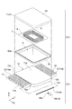
- FIG. 1 is an exploded perspective view of the coil device.
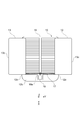
- FIG. 2 is a plan view of a heat dissipation unit provided in the coil device.
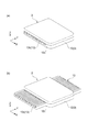
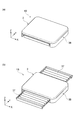
- Part (a) of FIG. 3 is a perspective view showing a storage form, and part (b) of FIG. 3 is a perspective view showing a heat release form.
- FIG. 4 is a diagram showing the configuration of a non-contact power feeding system provided with a coil device.
- FIG. 5 is a figure which shows the shift
- FIG. 6 is a view showing a coil device according to a modification.
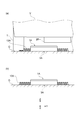
- Part (a) of FIG. 7 is a view showing the state of use of the coil device shown in FIG. 6, and part (b) of FIG.
- FIG. 7 is a view showing another state of use of the coil device shown in FIG. is there.
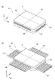
- Part (a) of FIG. 8 is a view showing a storage form of a coil device according to another modification
- part (b) of FIG. 8 is a view showing a heat release form of the coil device according to another modification.
- . 9A is a plan view of the coil device shown in FIG. 8A
- FIG. 9B is a plan view of the coil device shown in FIG.
- FIG. (A) part of FIG. 10 is a figure which shows the state which folded the heat dissipation sheet
- (b) part of FIG. 10 is a figure which shows the state which expanded the heat dissipation sheet.
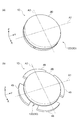
- Part (a) of FIG. 12 is a view showing the accommodation form of the coil device according to still another modification
- part (b) of FIG. 12 is a view showing the heat dissipation form of the coil device according to still another modification.
- Part (a) of FIG. 13 is a view showing a storage form of a coil device according to still another modification
- part (b) of FIG. 13 is a view showing a heat release form of the coil device according to still another modification. is there.
- the coil device accommodates the coil portion and includes a coil unit having a main surface and a heat dissipation unit thermally connected to the coil unit.
- the heat dissipation unit drives a heat dissipation body thermally connected to the main surface, a heat dissipation member movable with respect to the heat dissipation body, and thermally coupled to the heat dissipation body.
- a drive unit a drive unit.
- the heat dissipating unit includes a first form in which the heat dissipating member protrudes in a direction along the main surface from the heat dissipating body, and a second form in which the heat dissipating member is accommodated in the heat dissipating body.
- the heat dissipation body of the heat dissipation unit is thermally connected to the coil unit.
- the heat dissipating member is thermally connected to the heat dissipating body. Therefore, the heat generated in the coil part accommodated in the coil unit is transmitted to the heat dissipation member via the heat dissipation body.
- the heat dissipation member protrudes from the heat dissipation body in the direction along the main surface of the coil unit. Therefore, the heat dissipation area contributing to heat dissipation is expanded. As a result, the amount of heat release due to heat radiation and heat transfer to the air is increased. Therefore, the coil device can perform efficient heat dissipation.
- the heat dissipating member is housed in the heat dissipating body. Therefore, the coil device can be miniaturized. In other words, since the coil device includes the heat dissipating member which can be inserted into and removed from the heat dissipating body, it is possible to achieve both efficient heat dissipation and miniaturization.
- the heat dissipation unit When current is supplied to the coil portion, the heat dissipation unit may be in the first form. When current is supplied to the coil portion, the coil portion generates heat. When the coil portion generates heat, the heat dissipation unit is in the first form in which the heat dissipation member is protruded. Therefore, it is possible to efficiently dissipate the heat generated by the coil portion by the enlarged heat dissipation area. As a result, since the influence of heat on the coil unit is suppressed, the coil device can be operated stably.
- the length of the heat dissipating member protruding from the heat dissipating body may be a predetermined desired protruding length. According to this configuration, it is possible to obtain a heat dissipation form according to the form of heat generation.
- the coil device supplies power to the opposing coil device, or receives power from the opposing coil device, and when the heat dissipation unit is in the first form, the coil device has a length of the heat dissipation member protruding from the heat dissipation body It may be determined based on the amount of deviation between the coil portion and the coil portion provided in the opposing coil device.
- the coil portions shift.
- the displacement between the coil parts generates a leakage flux.
- the leakage magnetic flux causes the coil portion to generate heat according to the amount of deviation.
- the length of the heat dissipating member protruding from the heat dissipating body is determined based on the displacement between the coil portions. Therefore, the protrusion length of the heat dissipation member can be made to correspond to the temperature rise. As a result, the power required to drive the coil device can be reduced.
- the coil device is used in a noncontact power feeding system. As shown in FIG. 1, the coil device 1 includes a coil unit 2 and a heat dissipation unit 3.
- the coil unit 2 is a rectangular solid that has a rectangular shape in plan view.
- the coil unit 2 has a power transmission surface 2a and a base connection surface 2b (main surface).
- the power transmission surface 2 a faces another coil device 1.
- the base connection surface 2 b is fixed to the heat dissipation unit 3.
- the coil device 1 is overlapped in the order of the heat dissipation unit 3 and the coil unit 2 along the vertically upward direction (Z-axis direction). In other words, the coil unit 2 is disposed on the heat dissipation unit 3.
- the coil unit 2 has a housing 4, a coil 6 (coil portion), a coil holding plate 7, and a ferrite plate 8.
- the housing 4 has substantially the same shape as the heat dissipation unit 3 in plan view.
- the housing 4 forms a space for housing the coil 6, the coil holding plate 7, and the ferrite plate 8.
- the housing 4 has a case body 9 and a lid 11.
- the coil 6 is formed of a substantially rectangular spirally wound wire in the same plane.
- the coil 6 generates an induced current.
- the coil 6 is a so-called circular coil.
- a circular coil is a coil of the aspect by which conducting wire was wound around plane S in the plane spiral.
- the plane spiral shape is a shape in which the wire is wound from the outside to the inside or from the inside to the outside so as to surround the winding axis S.
- the coil 6 should just be an aspect by which the conducting wire was wound by plane spiral shape.
- the coil 6 may be single or multi-layered. Further, a plurality of winding axes S and a spiral shape may be provided in the same plane.
- the shape of the coil 6 viewed from the direction of the winding axis S may be various shapes such as a rectangle, a circle, and an ellipse.
- a lead for example, a litz wire in which a plurality of conductor strands insulated from each other are twisted may be used.
- the conducting wire may be a copper or aluminum single wire or a bus bar or the like.
- the coil may be a solenoid coil.
- the coil holding plate 7 is a flat member for holding the coil 6.
- the coil holding plate 7 is a so-called bobbin.
- the coil holding plate 7 has, for example, a groove in which the coil 6 is fitted.
- a material of the coil holding plate 7 a material having electrical insulation (for example, silicone, polyphenylene sulfide resin, etc.) is used.
- the groove in which the coil 6 is fitted may be provided in the lid 11.
- the coil 6 may be cured with an adhesive and / or a varnish. In this case, the coil holding plate 7 may be omitted.
- the ferrite plate 8 is, for example, a rectangular flat ferrite core.
- the ferrite plate 8 is a magnetic body, and controls the direction of magnetic lines of force generated from the coil 6. Also, the ferrite plate 8 converges the magnetic lines of force.
- the shape and size of the ferrite plate 8 may be substantially equal to the shape and size of the coil holding plate 7 in plan view, for example.
- the shape and size of the ferrite plate 8 are not limited to square.
- the ferrite plate 8 may be set to any shape and size that can be accommodated in the housing 4.
- the heat dissipation unit 3 is thermally connected to the coil unit 2 on the lower side of the coil unit 2.
- the heat dissipation unit 3 is disposed in contact with a road surface or the like.
- the heat dissipation unit 3 is nonmagnetic and conductive.
- the heat dissipation unit 3 is formed of a rigid material (for example, aluminum or copper).
- the heat dissipation unit 3 secures the overall rigidity of the coil device 1.
- the heat dissipation unit 3 shields the outflow of the leakage flux.
- the heat dissipation unit 3 dissipates the heat generated in the coil unit 2. In other words, the heat dissipation unit 3 has a so-called heat sink function.
- the heat dissipation unit 3 has a heat dissipation body 12, a pair of heat dissipation fins 13 (heat dissipation members), and a fin drive mechanism 14 (drive section).
- the heat dissipating body 12 has a housing connecting surface 12a (first mounting surface), a road surface connecting surface 12b (second mounting surface), and a fin side surface 12c.
- the heat dissipating body 12 has a fin accommodating portion 15 (see FIG. 2).
- the housing connection surface 12a is an upper surface when disposed on a road surface.
- the housing connection surface 12 a faces the base connection surface 2 b of the coil unit 2.
- the road surface connection surface 12 b is a lower surface when disposed on the road surface.
- the road surface connection surface 12b faces the road surface.
- the fin side surface 12 c connects the housing connection surface 12 a and the road surface connection surface 12 b.
- the fin housing portion 15 is a recess provided in the road surface connection surface 12b.
- the fin housing portion 15 has a fin opening 15a provided on the fin side surface 12c. The shape of the fin opening 15 a follows the outer shape of the heat dissipating fin 13.
- the heat dissipating fins 13 are movable relative to the heat dissipating body 12.
- the radiation fin 13 has a radiation surface 13 a and a movable surface 13 b.
- the heat dissipation surface 13 a has a plurality of convex portions D.
- the plurality of convex portions D respectively extend in the Y-axis direction.
- the plurality of convex portions D are separated from each other in the X-axis direction. According to such a shape, the surface area of the heat dissipation surface 13a is enlarged. As a result, efficient heat dissipation is performed.
- the heat dissipation surface 13 a is provided slidably with respect to the heat dissipation body 12.
- the heat dissipating surface 13 a always contacts the fin housing portion 15 of the heat dissipating body 12. This contact includes direct contact between the heat radiation surface 13a and the fin housing portion 15, and indirect contact via a member such as grease. For example, a slight gap is provided between the heat dissipation surface 13 a and the fin housing portion 15. Thermally conductive silicone and / or oil or the like that does not volatilize naturally may be disposed in this gap. A heat conductive silicone sheet having abrasion resistance may be inserted into the gap. According to such a configuration, the heat dissipating fins 13 can be smoothly inserted into and removed from the heat dissipating body 12, and heat can be efficiently transmitted from the heat dissipating body 12 to the heat dissipating fins 13.
- the movable surface 13b is provided below the heat dissipation surface 13a. Movable surface 13 b faces the road surface. The movable surface 13b is not fixed to the road surface. Therefore, the movable surface 13b is movable relative to the road surface. For example, the movable surface 13 b is formed slightly above the road surface connecting surface 12 b of the heat dissipation body 12. That is, a gap may be formed between the movable surface 13b and the road surface G (see FIG. 4).
- the fin drive mechanism 14 reciprocates the pair of heat dissipating fins 13 in the Y-axis direction.
- the fin drive mechanism 14 has a worm gear 17 and a motor 18.
- the worm gear 17 is a component in which a rod-shaped body extending in the Y-axis direction is provided with a spiral tooth shape.
- One end of the worm gear 17 is screwed into one of the radiation fins 13.
- the other end of the worm gear 17 is screwed into the other radiation fin 13.
- the motor 18 has a gear 18 a that meshes with the tooth shape of the worm gear 17.
- the motor 18 supplies torque to the worm gear 17 via the gear 18a.
- the motor 18 can rotate in the forward and reverse directions.
- the motor 18 rotates the worm gear 17 by a predetermined number of revolutions.
- the desired overhang length is, for example, a length necessary for the temperature of a predetermined location of the power transmission coil device 24 to fall below a threshold.
- the desired protruding length is, for example, a length necessary to suppress an increase in temperature of a predetermined location of the power transmission coil device 24.
- the power consumption of the motor 18 can be reduced by setting the extension length to a minimum length to make the temperature be below the threshold and / or to suppress the temperature rise. Further, the possibility of the vehicle V stepping on the radiation fin 13 can be reduced.
- the fin drive mechanism 14 shown in FIG. 1 drives the pair of heat dissipating fins 13 by one worm gear 17.
- the projecting lengths of the pair of heat dissipating fins 13 are always the same.
- the length of one of the radiation fins 13 may be different from the protruding length of the other radiation fin 13.
- one heat dissipating fin 13 may be accommodated in the heat dissipating body 12 and only the other heat dissipating fin 13 may be protruded.
- the fin drive mechanism 14 is provided on each of the heat radiation fin 13 and the other heat radiation fin 13. It suffices to have a fin drive mechanism for driving one of the radiation fins 13 and a fin drive mechanism for driving the other radiation fin.
- the heat dissipation unit 3 has two or more different forms.
- the part (a) of FIG. 3 shows the form (housing form, 2nd form) which accommodated the radiation fin 13 in the thermal radiation body 12.
- FIG. The part (b) of FIG. 3 shows the form (heat radiation form, 1st form) which protruded the radiation fin 13 from the thermal radiation body 12.
- the coil device 1 thermally connects the heat dissipation body 12 of the heat dissipation unit 3 to the coil unit 2.
- the heat dissipating body 12 is thermally connected to the heat dissipating fins 13. Therefore, the heat generated in the coil 6 accommodated in the coil unit 2 is transmitted to the heat dissipating fins 13 via the heat dissipating body 12.
- the heat dissipating fins 13 project from the heat dissipating body 12 in a direction (Y-axis direction) intersecting the winding axis S (see FIG. 1). Therefore, the heat dissipation area contributing to heat dissipation is expanded. As a result, efficient heat dissipation can be performed.
- the radiation fin 13 is accommodated in the radiation body 12. Therefore, the coil device 1 can be miniaturized. Therefore, the coil device 1 can achieve both efficient heat dissipation and miniaturization by the heat dissipating fins 13 that can be taken in and out from the heat dissip
- the operation of setting the housing mode and the operation of setting the heat radiation mode may correspond to the power feeding operation to another coil device 1.
- the feeding operation when the feeding operation is not performed, no current is supplied to the coil 6. Accordingly, since the coil 6 does not generate heat, it is not necessary to actively dissipate heat. Then, the radiation fin 13 is accommodated in the radiation body 12 (housing form). According to the storage form, the coil device 1 can be miniaturized.
- current is supplied to the coil 6. Therefore, since the coil 6 generates heat, it actively dissipates heat. Then, the radiation fin 13 is made to project from the thermal radiation body 12 (heat radiation form). According to the heat dissipation form, the heat dissipation area contributing to heat dissipation is expanded. As a result, the heat dissipation efficiency can be enhanced.
- the non-contact electric power feeding system provided with the coil apparatus 1 which concerns on embodiment is demonstrated.
- the non-contact power feeding system 21 charges a battery 29 mounted on a vehicle V such as an electric car and a hybrid car.
- the non-contact power feeding system 21 supplies power directly to a drive source such as a motor.
- the vehicle V includes components necessary for traveling such as a motor, an operation handle, and a brake. However, illustration of these configurations is omitted in FIG.
- the non-contact power feeding system 21 includes a power transmission device 22 installed on the road surface G, and a power reception device 23 provided on the vehicle V side.
- the power transmission device 22 and the power reception device 23 each include the coil device 1 according to the embodiment.
- the coil device 1 included in the power transmission device 22 is referred to as a power transmission coil device 24.
- the coil device 1 included in the power reception device 23 is referred to as a power reception coil device 26 (a counterpart coil device).
- the coil 6 see FIG. 1 included in the power transmitting coil device 24 and the coil 6 included in the power receiving coil device 26 (counterpart coil portion) approach each other. In this proximity state, the pair of coils 6 form an electromagnetic coupling circuit.
- the electromagnetic coupling circuit performs non-contact power supply from the coil 6 on the power transmission side to the coil 6 on the power reception side by electromagnetic coupling of the coils 6 with each other.
- the electromagnetic coupling circuit may be an electromagnetic induction coupling circuit or a magnetic resonance coupling circuit.
- the power transmission coil device 24 and the power reception coil device 26 face each other in the vertical direction, and are separated at a predetermined interval.
- the power transmission coil device 24 protrudes upward from the road surface G.
- the power receiving coil device 26 is attached to the lower surface of the chassis B of the vehicle V, for example.
- the power receiving device 23 includes a power receiving coil device 26 (coil device), a power receiving circuit 27, and a charging circuit 28.
- the power receiving coil device 26 receives the power (AC power) supplied contactlessly from the power transmission coil device 24 on the power transmission side.
- the power receiving circuit 27 converts AC power from the power receiving coil device 26 into DC power. Then, the power receiving circuit 27 outputs DC power to the charging circuit 28.
- the charging circuit 28 converts the power (DC power) from the power receiving circuit 27 into desired power.
- the charging circuit 28 supplies the desired power to the battery 29.
- the battery 29 is a rechargeable battery mounted on the vehicle V.
- the battery 29 is, for example, a secondary battery such as a lithium ion battery and a nickel hydrogen battery.
- the battery 29 supplies power to a traveling motor (not shown) and the like.
- the power transmission device 22 includes a power transmission coil device 24 (coil device), a power transmission circuit 31, a rectifier circuit 32, and a control device 34.
- the power transmission coil device 24 is installed on the road surface G.
- the power transmission circuit 31 converts the power supplied from the rectifier circuit 32 into alternating current power (high frequency power).
- the power transmission circuit 31 provides AC power to the power transmission coil device 24.
- the rectifier circuit 32 rectifies AC power supplied from the external power supply 33. In other words, the rectifier circuit 32 converts AC power into DC power.
- the rectifier circuit 32 may be omitted when the external power supply 33 is a DC power supply.
- the external power supply 33 supplies the vehicle V with the power necessary to generate the power to be transmitted.
- the control device 34 which is an electronic control unit, includes, for example, a central processing unit (CPU), a read only memory (ROM), a random access memory (RAM), and the like.
- the control device 34 controls each circuit (the rectifier circuit 32, the power transmission circuit 31 and the like) of the power transmission device 22.
- the control device 34 controls the heat dissipation operation of the power transmission coil device 24. Specifically, the controller 34 supplies a control signal to the motor 18 (see FIG. 1). The control signal is related to the protrusion length of the radiation fin 13. The protruding length of the radiation fin 13 is related to the number of rotations of the motor 18. Accordingly, the controller 34 rotates the motor 18 the number of rotations corresponding to the protrusion length.
- the control device 34 controls the radiation fin 13 so as to be in the storage form (see part (a) of FIG. 3).
- the outer end surface 13c of the heat dissipating fin 13 may be flush with the fin side surface 12c.
- the outer end surface 13c may be disposed on the back side with respect to the fin side surface 12c.
- the outer end surface 13c may slightly protrude from the fin side surface 12c.
- the control device 34 controls the heat dissipating fins 13 so as to be in the heat dissipating mode (see part (b) of FIG. 3).
- the heat radiation form means a form in which the heat radiation fin 13 protrudes from the fin side surface 12 c by a predetermined length.
- the predetermined length may be a length when the heat dissipating fins 13 are mechanically most projected.
- the predetermined length may be determined using various variables related to the non-contact power feeding system 21. For example, the predetermined length may be determined based on the amount of positional deviation between the power transmission coil device 24 and the power reception coil device 26. Alternatively, it may be determined based on the amount of positional deviation between the coil 6 of the power transmission coil device 24 and the coil 6 of the power reception coil device 26.
- the positional deviation may be described by the transmission efficiency between the power transmission coil device 24 and the power reception coil device 26.
- the absence of positional deviation may be described as the positional relation at which the maximum transmission efficiency is realized.
- a state in which the center of the surface of one coil 6 in the front-rear direction (X-axis direction) coincides with the center of the surface of the other coil 6 in the front-rear direction in the vertical direction (Z-axis direction) It may be described that It may be described that the positional deviation does not occur is a positional relationship defined as no positional deviation in a specification or a use manual of the non-contact power feeding system in which the power transmission coil device 24 is used.
- the difference between the reference position and the actual position indicating that no positional deviation has occurred may be defined as positional deviation.
- the position of the power receiving coil device 26 is shifted in the horizontal direction (Y axis direction) with respect to the power transmitting coil device 24.
- the radiation fin 13 is a soft magnetic material (for example, soft ferrite).
- regions R1 and R2 in which the power transmission coil device 24 and the power reception coil device 26 do not overlap each other are generated. According to these regions R1 and R2, there is a possibility that leakage magnetic flux may occur between the power transmission coil device 24 and the power reception coil device 26. If leakage flux occurs, the desired transmission efficiency may not be obtained.
- the control device 34 controls the projecting lengths L1 and L2 of the radiation fin 13 so as to eliminate the non-overlapping regions R1 and R2.
- the protruding lengths L1 and L2 are lengths from the fin side surface 12c of the heat dissipation body 12 to the outer end surface 13c of the heat dissipation fin 13.
- the control device 34 makes the protrusion length L1 of the other radiation fin 13 longer than the protrusion length L2 of the one radiation fin 13. According to such control, leakage flux can be suppressed. As a result, a reduction in transmission efficiency can be suppressed.
- the power transmission coil device 24 also has a heat dissipation unit, similar control may be performed. In this case, the leakage flux can be further suppressed. Therefore, the decrease in transmission efficiency can be further suppressed.
- the operation of switching between the storage form of the radiation fin 13 and the radiation form does not have to be strictly synchronized with the current supply operation to the coil 6.
- the synchronization means that the current supply to the coil 6 is started and the operation of projecting the radiation fin 13 is started at the same time as the current supply to the coil 6 is continued, the heat radiation form is maintained.
- the transition from the heat radiation form to the accommodation form is started, and the accommodation form is maintained while the current supply to the coil 6 is stopped.
- the radiation fin 13 is stepped on. Can be suppressed.
- the power transmission coil apparatus 24 should just be made into the thermal radiation form, at least, while the electric current supply to the coil 6 is continuing. Therefore, when the current supply to the coil 6 is stopped, it is not necessary to immediately shift from the heat radiation form to the accommodation form. For example, after the current supply to the coil 6 is stopped and a predetermined time has elapsed, the heat dissipation mode may be shifted to the accommodation mode. The timing of this transition may be, for example, when the temperature at a predetermined location of the power transmission coil device 24 falls below a threshold. According to such control, when the vehicle V which has been charged is moved and another vehicle V is immediately moved onto the power transmission coil device 24, the radiation fin 13 is maintained in the protruding state.
- the power for driving the radiation fins 13 can be reduced. Furthermore, there is no time for the heat dissipating fins 13 to move in and out. As a result, the use efficiency of the non-contact power feeding system 21 can be enhanced.
- the coil device of the present disclosure has been described above in detail based on the embodiments. However, the coil device of the present disclosure is not limited to the above embodiment. The coil device of the present disclosure can be variously modified without departing from the scope of the invention.
- the heat dissipating member is not limited to a metal material as long as the material has good thermal conductivity. In addition to good thermal conductivity, a material further having flexibility and shape memory characteristics may be adopted as the material constituting the heat dissipation member. Such materials include shape memory alloys and silicon.
- the coil device 1A includes a coil unit 2 and a heat dissipation unit 3A.
- the heat dissipation unit 3A has a heat dissipation fin 13A (heat dissipation member).
- the radiation fin 13A has a convex portion DA extending parallel to the fin side surface 12c.
- the plurality of convex portions DA are provided to be separated from each other in the drive direction (Y-axis direction).
- the heat dissipating fins 13A employing such a material, as shown in the portion (a) of FIG. 7, since the heat dissipating fins 13A deform when the heat dissipating fins 13A are stepped on the tire T, the tire T The influence to the vehicle V which it has can be suppressed. Therefore, the vehicle V will not be injured. As shown in part (b) of FIG. 7, the heat radiation fin 13A recovers a predetermined shape after a predetermined time has elapsed.
- the heat dissipation member is not limited to one that maintains a predetermined shape by having a predetermined rigidity.
- the coil device 1B has a coil unit 2 and a heat dissipation unit 3B.
- the heat release unit 3B has a heat release sheet 37 (heat release member).
- the heat dissipation sheet 37 may be made of a flexible material such as a sheet member.
- the heat-radiating sheet 37 formed of such a material has a folded shape for storage (see the form in FIG. 8A) and an extended shape for heat radiation (the form of heat radiation in FIG. b) see section).
- the heat dissipation unit 3B shown in (a) of FIG. 9 and (b) of FIG. 9 includes a heat dissipation sheet 37, a support 38, a guide bar 39, a rack 41, and a motor 42.
- the support 38 is attached to the leading edge of the heat dissipation sheet 37.
- the tip of the guide bar 39 is fixed to one end of the support 38.
- the proximal end side of the guide bar 39 is slidably supported by a guide rail 43 provided on the heat dissipation body 12A.
- the tip of the rack 41 is fixed to the other end of the support 38.
- the rack 41 meshes with the pinion gear 44 of the motor 42 attached to the heat dissipation body 12A.
- the pinion gear 44 is rotated.
- the rack 41 moves linearly.
- the columns 38 attached to the rack 41 move. Therefore, the heat dissipation sheet 37 can be deployed and accommodated.
- the heat dissipation sheet 37 can be compactly accommodated (see part (a) of FIG. 9). Therefore, the space P for mounting various components on the heat dissipation body 12A can be secured.
- the configuration for folding the heat dissipation sheet is not particularly limited. As shown in FIGS. 8 and 9, in addition to the configuration in which the heat-radiating sheet is folded in an accordion manner, the heat radiation shown in FIG. 10 (a) (accommodated state) and FIG. 10 (b) (heat radiated). As in the case of the sheet 37A, a so-called Miura fold may be employed.
- the direction in which the heat dissipation member protrudes is not limited to one axial direction.
- the coil device 1C has a coil unit 2 and a heat dissipation unit 3C.
- the heat radiation unit 3C is a second heat radiation fin that can protrude in the direction of the second axis A2 (X axis direction) in addition to the pair of first heat radiation fins 46 that can protrude in the direction of the first axis A1 (Y axis direction). It may have 47.
- the second axis A2 is orthogonal to the first axis A1. According to such a configuration, since the heat radiation area can be increased, the heat radiation efficiency can be further improved.
- the shape of the heat dissipation body 12 is not limited to a rectangular shape in plan view.
- the coil device 1D includes a coil unit 2D and a heat dissipation unit 3D.
- the heat dissipation body 12D of the heat dissipation unit 3D may have a circular shape in plan view.
- coil apparatus 1D may have the 1st radiation fin 48 and the 2nd radiation fin 49 which protrude in a mutually different direction.
- the operation of taking the heat dissipating member into and out of the heat dissipating body is not limited to the operation of moving the heat dissipating member in a linear manner as in the coil device 1 of the first embodiment.
- the coil device 1E has a coil unit 2E and a heat dissipation unit 3E.
- the heat dissipation member of the heat dissipation unit 3E is a plate-shaped heat dissipation plate 51.
- the heat dissipating plate 51 is rotated around the drive shaft S1 and spreads like a fan.
- the heat dissipation unit 3E of the coil device 1E has a plurality of heat dissipation plates 51.
- a drive shaft mechanism (not shown) is provided at the corner of the heat dissipation plate 51. The drive shaft mechanism drives each of the heat dissipation plates 51 to a different rotational position.
- the above embodiment has described the case where the coil device of the present disclosure is applied to a non-contact power feeding system.
- the coil device of the present disclosure is not limited to the application to the noncontact power feeding system.
- the coil device of the present disclosure can also be applied to a coil device used in an environment where there is no counterpart coil device.
- the coil devices of the present disclosure may be applied to induction heating systems and / or eddy current flaw detection systems.
- the coil device of the present disclosure can achieve both efficient heat dissipation and miniaturization.
Landscapes
- Engineering & Computer Science (AREA)
- Power Engineering (AREA)
- Mechanical Engineering (AREA)
- Transportation (AREA)
- Computer Networks & Wireless Communication (AREA)
- Electric Propulsion And Braking For Vehicles (AREA)
- Coils Of Transformers For General Uses (AREA)
- Current-Collector Devices For Electrically Propelled Vehicles (AREA)
- Transformer Cooling (AREA)
Abstract
コイル装置は、コイルを収容するコイルユニットと、コイルユニットに対して熱的に接続された放熱ユニットと、を備える。放熱ユニットは、放熱ボディと、放熱ボディに対して移動可能である放熱フィンと、放熱フィンを駆動するフィン駆動機構と、を有する。放熱ユニットは、放熱フィンが放熱ボディから巻軸に対して交差する方向に突出した放熱形態と、放熱フィンが放熱ボディに収容された収容形態と、を含む。
Description
本開示は、コイル装置に関する。
特許文献1,2は、非接触給電装置において、コイルが発する熱に注目した技術を開示する。特許文献1の非接触給電装置は、液体式の冷却機構を有する。具体的には、特許文献1の非接触給電装置は、流体を流通させる流路を備える。コイルが発する熱は、流路を流れる液体に吸収される。特許文献2の非接触給電装置は、断熱性を有する隔壁を利用して電子部品を熱的に保護する。特許文献2の非接触給電装置は、熱伝導率が高い部材を利用して送電コイルが発するジュール熱を外部に放出する。
非接触給電装置に関する分野においては、導電中のコイルが発する熱を効率よく放出することが望まれている。特許文献1の非接触給電装置は、液体式の冷却機構によって、コイルが発する熱を効率よく放熱する。しかし、液体式の冷却機構は、コイル装置内に流路を設ける必要がある。さらに、液体式の冷却機構は、液体を流動させるためのポンプといった付帯装置を要する。従って、非接触給電装置の小型化を阻害するおそれがある。
本開示は、効率のよい放熱と小型化との両立が可能なコイル装置を説明する。
本開示の一形態は、コイル装置である。コイル装置は、コイル部を収容すると共に、主面を有するコイルユニットと、コイルユニットに対して熱的に接続された放熱ユニットと、を備える。放熱ユニットは、主面に対して熱的に接続された放熱ボディと、放熱ボディに対して移動可能であると共に、放熱ボディに対して熱的に接続された放熱部材と、放熱部材を駆動する駆動部と、を有する。放熱ユニットは、放熱部材が放熱ボディから主面に沿う方向に突出した第1形態と、放熱部材が放熱ボディに収容された第2形態と、を含む。
本開示のコイル装置によれば、効率のよい放熱と小型化との両立が可能である。
本開示の一形態は、コイル装置である。コイル装置は、コイル部を収容すると共に、主面を有するコイルユニットと、コイルユニットに対して熱的に接続された放熱ユニットと、を備える。放熱ユニットは、主面に対して熱的に接続された放熱ボディと、放熱ボディに対して移動可能であると共に、放熱ボディに対して熱的に接続された放熱部材と、放熱部材を駆動する駆動部と、を有する。放熱ユニットは、放熱部材が放熱ボディから主面に沿う方向に突出した第1形態と、放熱部材が放熱ボディに収容された第2形態と、を含む。
コイル装置は、コイルユニットに対して放熱ユニットの放熱ボディが熱的に接続される。放熱ボディには、放熱部材が熱的に接続される。従って、コイルユニットに収容されたコイル部において生じた熱は、放熱ボディを介して放熱部材に伝わる。放熱部材は、放熱ボディからコイルユニットの主面に沿う方向に突出する。従って、放熱に寄与する放熱面積が拡大する。その結果、熱放射と空気への熱伝達とによる放熱量が増大する。従って、コイル装置は、効率のよい放熱を行うことができる。放熱部材は、放熱ボディに収容される。従って、コイル装置は、小型化することができる。換言すると、コイル装置は、放熱ボディに対して出し入れ可能な放熱部材を備えるので、効率のよい放熱と小型化とを両立させることができる。
コイル部に電流が供給されているとき、放熱ユニットは第1形態であってもよい。コイル部に電流が供給されているとき、コイル部は発熱する。コイル部が発熱しているとき、放熱ユニットは、放熱部材を突出させた第1形態である。従って、拡大された放熱面積により、コイル部が発生させる熱を効率よく放熱することが可能になる。その結果、コイルユニットへの熱の影響が抑制されるので、コイル装置を安定して動作させることができる。
放熱ユニットが第1形態であるとき、放熱ボディから突出した放熱部材の長さは、予め設定された所望の突出し長さとされてもよい。この構成によれば、発熱の態様に応じた放熱形態を得ることができる。
コイル装置は、相手方コイル装置に対して電力供給し、又は、相手方コイル装置から電力を受け取り、放熱ユニットが第1形態であるとき、放熱ボディから突出した放熱部材の長さは、コイル装置が備えるコイル部と相手方コイル装置が備えるコイル部とのずれ量に基づいて決定されてもよい。コイル装置と相手方コイル装置との間にずれが生じると、コイル部同士のずれが生じる。コイル部同士のずれは、漏れ磁束を発生させる。漏れ磁束は、ずれ量に応じたコイル部の発熱を生じさせる。放熱ボディから突出した放熱部材の長さは、コイル部同士のずれに基づいて決定される。従って、放熱部材の突出し長さを、温度上昇に応じた長さとすることが可能になる。その結果、コイル装置の駆動に要する動力を低減することができる。
以下、添付図面を参照しながら本開示のコイル装置について説明する。図面の説明において同一の要素には同一の符号を付し重複する説明を省略する。また、図面の説明において、図中に示す直交座標系を用いる場合がある。以下の説明において、「前」は、X方向正の向きと対応する。「後」は、X方向負の向きと対応する。「左」は、Y方向正の向きと対応する。「右」は、Y方向負の向きと対応する。「上」は、Z方向正の向きと対応する。「下」は、Z方向負の向きと対応する。
コイル装置は、非接触給電システムに用いられる。図1に示されるように、コイル装置1は、コイルユニット2と、放熱ユニット3と、を有する。
コイルユニット2は、平面視して矩形を呈する直方体である。コイルユニット2は、送電面2aとベース連結面2b(主面)とを有する。送電面2aは、別のコイル装置1に対面する。ベース連結面2bは、放熱ユニット3に固定される。コイル装置1は、鉛直上向き方向(Z軸方向)に沿って、放熱ユニット3、コイルユニット2の順に重なっている。換言すると、コイルユニット2は、放熱ユニット3の上に配置されている。コイルユニット2は、ハウジング4と、コイル6(コイル部)と、コイル保持板7と、フェライト板8と、を有する。
ハウジング4は、平面視して放熱ユニット3と略同じ形状を有する。ハウジング4は、コイル6と、コイル保持板7と、フェライト板8と、を収容する空間を形成する。ハウジング4は、ケース本体9と、蓋体11と、を有する。
コイル6は、同一平面内で略矩形の渦巻状に巻回された導線によって形成される。コイル6は、誘導電流を発生させる。コイル6は、いわゆるサーキュラーコイルである。サーキュラーコイルとは、導線が巻軸Sのまわりに平面渦巻状に巻回された態様のコイルである。平面渦巻状とは、巻軸Sを囲むように外側から内側へ、もしくは内側から外側へ導線が巻かれている形状である。コイル6は、導線が平面渦巻状に巻回された態様であればよい。従って、コイル6は、一層であっても多層であってもよい。また、巻軸Sおよび渦巻状は、同一平面内に複数個設けられてもよい。巻軸Sの方向から見たコイル6の形状は、矩形、円形、楕円形等の種々の形状であってもよい。導線としては、例えば、互いに絶縁された複数の導体素線が撚り合わされたリッツ線を用いてもよい。導線は、銅もしくはアルミニウムの単線、又はバスバー等であってもよい。なお、コイルは、ソレノイドコイルであってもよい。
コイル保持板7は、コイル6を保持するための平板状部材である。コイル保持板7は、いわゆるボビンである。コイル保持板7は、例えば、コイル6が嵌め込まれる溝部を有する。コイル保持板7の材料としては、電気絶縁性を有する材料(例えばシリコーン、ポリフェニレンサルファイド樹脂等)が用いられる。コイル6が嵌め込まれる溝部は、蓋体11に設けられてもよい。また、コイル6を接着材及び/又はワニスで硬化させてもよい。この場合にはコイル保持板7を略しても良い。
フェライト板8は、例えば矩形平板状のフェライトコアである。フェライト板8は、磁性体であって、コイル6から発生した磁力線の方向を制御する。また、フェライト板8は、磁力線を収束する。フェライト板8の形状及び大きさは、例えば、平面視において、コイル保持板7の形状及び大きさに略等しくてもよい。フェライト板8の形状及び大きさは、正方形に限定されない。フェライト板8は、ハウジング4に収容可能である任意の形状及び大きさに設定してよい。
放熱ユニット3は、コイルユニット2の下側においてコイルユニット2に対して熱的に接続される。放熱ユニット3は、路面などに接するように配置される。放熱ユニット3は、非磁性及び導電性を有する。放熱ユニット3は、剛性の高い材料(例えばアルミニウム又は銅等)で形成されている。放熱ユニット3は、コイル装置1の全体としての剛性を確保する。放熱ユニット3は、漏れ磁束の外部流出を遮蔽する。放熱ユニット3は、コイルユニット2において生じる熱を放熱する。換言すると、放熱ユニット3は、いわゆるヒートシンクの機能を有する。
図1及び図2に示されるように、放熱ユニット3は、放熱ボディ12と、一対の放熱フィン13(放熱部材)と、フィン駆動機構14(駆動部)と、を有する。放熱ボディ12は、ハウジング連結面12a(第1取付面)と、路面連結面12b(第2取付面)と、フィン側面12cと、を有する。放熱ボディ12は、フィン収容部15(図2参照)を有する。ハウジング連結面12aは、路面に配置された場合における上側の面である。ハウジング連結面12aは、コイルユニット2のベース連結面2bに対面する。路面連結面12bは、路面に配置された場合における下側の面である。路面連結面12bは、路面に対面する。フィン側面12cは、ハウジング連結面12aと、路面連結面12bと、を連結する。フィン収容部15は、路面連結面12bに設けられた凹部である。フィン収容部15は、フィン側面12cに設けられたフィン開口15aを有する。フィン開口15aの形状は、放熱フィン13の外形形状に倣う。
放熱フィン13は、放熱ボディ12に対して相対的に移動可能である。放熱フィン13は、放熱面13aと可動面13bとを有する。放熱面13aは、複数の凸部Dを有する。複数の凸部Dは、それぞれY軸方向に延在する。複数の凸部Dは、X軸方向に互いに離間する。このような形状によれば、放熱面13aの表面積が拡大される。その結果、効率のよい放熱が行われる。放熱面13aは、放熱ボディ12に対して摺動可能に設けられる。放熱面13aは、放熱ボディ12のフィン収容部15に常に接触する。この接触には、放熱面13aとフィン収容部15との直接的な接触と、グリスといった部材を介した間接的な接触と、を含む。例えば、放熱面13aとフィン収容部15との間には、僅かな隙間が設けられる。この隙間には、自然揮発しない熱伝導性シリコーン及び/又はオイルなどが配置されてもよい。隙間には、耐摩耗性を有する熱伝導性シリコーンシートが挟み込まれてもよい。このような構成によれば、放熱ボディ12に対する放熱フィン13の出し入れを円滑に行うことが可能であると共に、放熱ボディ12から放熱フィン13へ熱を効率よく伝えることができる。
可動面13bは、放熱面13aに対して下側に設けられる。可動面13bは、路面と対面する。可動面13bは、路面に対して固定されていない。従って、可動面13bは路面に対して相対的に移動可能である。例えば、可動面13bは、放熱ボディ12の路面連結面12bよりも僅かに上側に形成される。つまり、可動面13bと路面G(図4参照)との間には、隙間が形成されてもよい。
フィン駆動機構14は、一対の放熱フィン13をY軸方向に往復移動させる。フィン駆動機構14は、ウォームギヤ17とモータ18とを有する。ウォームギヤ17は、Y軸方向に延在する棒体にらせん状の歯型を設けた部品である。ウォームギヤ17の一端は、一方の放熱フィン13にねじ込まれる。ウォームギヤ17の他端は、他方の放熱フィン13にねじ込まれる。モータ18は、ウォームギヤ17の歯形に噛み合うギヤ18aを有する。モータ18は、当該ギヤ18aを介してトルクをウォームギヤ17に供給する。モータ18は、正回転及び逆回転が可能である。また、モータ18は、所定の回転数だけウォームギヤ17を回転させる。ウォームギヤ17の回転数を所定の回数に設定することにより、放熱フィン13の突出し長さを所望の長さに制御することができる。所望の突出し長さとは、例えば、送電コイル装置24の所定箇所の温度が閾値を下回るために必要な長さである。また、所望の突出し長さとは、例えば、送電コイル装置24の所定箇所の温度の上昇を抑えるために必要な長さである。突出し長さを、温度を閾値以下にするため及び/又は温度上昇を抑えるために必要最低限の長さにすることにより、モータ18の消費電力の低減を実現できる。また、車両Vが放熱フィン13を踏む可能性を低減することができる。
図1に示されたフィン駆動機構14は、1本のウォームギヤ17によって一対の放熱フィン13を駆動した。この構成によれば、一対の放熱フィン13の突出長さは、常に同じである。しかし、一方の放熱フィン13の長さを、他方の放熱フィン13の突出し長さと異ならせてもよい。例えば、一方の放熱フィン13を放熱ボディ12に収容した状態とし、他方の放熱フィン13だけ突出させてもよい。このような動作をさせる場合には、一方の放熱フィン13及び他方の放熱フィン13のそれぞれに、フィン駆動機構14を設ける。一方の放熱フィン13を駆動するためのフィン駆動機構と、他方の放熱フィンを駆動するためのフィン駆動機構とを有していればよい。
図3の(a)部及び図3の(b)部に示されるように、放熱ユニット3は、互いに異なる2以上の形態を有する。図3の(a)部は、放熱フィン13を放熱ボディ12に収容した形態(収容形態、第2形態)を示す。図3の(b)部は、放熱フィン13を放熱ボディ12から突き出した形態(放熱形態、第1形態)を示す。
コイル装置1は、コイルユニット2に対して放熱ユニット3の放熱ボディ12を熱的に接続する。放熱ボディ12は、放熱フィン13に熱的に接続される。従って、コイルユニット2に収容されたコイル6において生じた熱は、放熱ボディ12を介して放熱フィン13に伝わる。放熱フィン13は、放熱ボディ12から巻軸S(図1参照)に対して交差する方向(Y軸方向)に突出する。従って、放熱に寄与する放熱面積が拡大する。その結果、効率のよい放熱を行うことができる。そして、放熱フィン13は、放熱ボディ12に収容される。従って、コイル装置1を小型化することができる。従って、放熱ボディ12に対して出し入れ可能な放熱フィン13により、コイル装置1は、効率のよい放熱と小型化とを両立させることができる。
収容形態に設定する動作と放熱形態に設定する動作とは、別のコイル装置1への給電動作に対応させてよい。例えば、給電動作を行わないときには、コイル6に電流が供給されない。従って、コイル6は発熱しないので、積極的な放熱を行う必要がない。そこで、放熱フィン13を放熱ボディ12に収容する(収容形態)。収容形態によれば、コイル装置1を小型化できる。一方、給電動作を行うときには、コイル6に電流が供給される。従って、コイル6が発熱するので、積極的な放熱を行う。そこで、放熱フィン13を放熱ボディ12から突出させる(放熱形態)。放熱形態によれば、放熱に寄与する放熱面積が拡大される。その結果、放熱効率を高めることができる。
実施形態に係るコイル装置1を備えた非接触給電システムについて説明する。図4に示されるように、非接触給電システム21は、電気自動車及びハイブリッド自動車等の車両Vに搭載されたバッテリ29を充電する。非接触給電システム21は、モータ等の駆動源に対して直接に電力を供給する。車両Vは、モータ、操作ハンドル、及びブレーキ等の走行に必要な構成を含む。しかし、図4ではこれらの構成の図示を省略する。
非接触給電システム21は、路面Gに設置された送電装置22と、車両V側に設けられる受電装置23と、を含む。送電装置22及び受電装置23は、それぞれ実施形態に係るコイル装置1を有する。以下、送電装置22が有するコイル装置1を送電コイル装置24と称する。受電装置23が有するコイル装置1を受電コイル装置26(相手方コイル装置)と称する。送電コイル装置24と受電コイル装置26とが近接すると、送電コイル装置24に含まれるコイル6(図1参照)と受電コイル装置26(相手方コイル部)に含まれるコイル6とが互いに近接する。この近接状態では、一対のコイル6によって電磁結合回路が形成される。電磁結合回路は、コイル6同士の電磁気的な結合によって、送電側のコイル6から受電側のコイル6への非接触の給電を行う。電磁結合回路は、電磁誘導方式の結合回路であってもよく、磁界共鳴方式の結合回路であってもよい。
送電コイル装置24及び受電コイル装置26は、上下方向において互いに向き合うと共に、所定の間隔で離間する。送電コイル装置24は、路面Gから上方に突出する。受電コイル装置26は、例えば車両VのシャシーBの下面に取り付けられる。
受電装置23は、受電コイル装置26(コイル装置)と、受電回路27と、充電回路28と、を含む。受電コイル装置26は、送電側の送電コイル装置24から非接触で供給される電力(交流電力)を受け取る。受電回路27は、受電コイル装置26からの交流電力を直流電力に変換する。そして、受電回路27は、直流電力を充電回路28に出力する。充電回路28は、受電回路27からの電力(直流電力)を所望電力に変換する。充電回路28は、所望電力をバッテリ29に供給する。バッテリ29は、車両Vに搭載された再充電が可能な電池である。バッテリ29は、例えば、リチウムイオン電池及びニッケル水素電池等の二次電池である。バッテリ29は、図示しない走行モータ等に電力を供給する。
送電装置22は、送電コイル装置24(コイル装置)と、送電回路31と、整流回路32と、制御装置34と、を有する。
送電コイル装置24は、路面Gに設置される。
送電回路31は、整流回路32から供給される電力を交流電力(高周波電力)に変換する。送電回路31は、交流電力を送電コイル装置24に提供する。
整流回路32は、外部電源33から供給される交流電力を整流する。換言すると、整流回路32は、交流電力を直流電力に変換する。整流回路32は、外部電源33が直流電源である場合には、省略してもよい。
外部電源33は、車両Vに伝送すべき電力を生成するために必要となる電力を供給する。
電子制御ユニットである制御装置34は、例えば、CPU[Central Processing Unit]、ROM[Read Only Memory]、RAM[Random Access Memory]等を含む。制御装置34は、送電装置22の各回路(整流回路32、送電回路31等)を制御する。
制御装置34は、送電コイル装置24の放熱動作を制御する。具体的には、制御装置34は、制御信号をモータ18(図1参照)に供給する。制御信号は、放熱フィン13の突出し長さに関連する。放熱フィン13の突出し長さは、モータ18の回転回数に関連する。従って、制御装置34は、突出し長さに対応する回転回数だけモータ18を回転させる。
制御装置34は、送電コイル装置24へ電流が供給されていないとき、収容形態(図3の(a)部参照)となるように放熱フィン13を制御する。収容形態であるとき、放熱フィン13の外側端面13cは、フィン側面12cと面一であってもよい。なお、外側端面13cは、フィン側面12cに対して奥側に配置されてもよい。外側端面13cは、フィン側面12cから僅かに突出してもよい。
制御装置34は、送電コイル装置24へ電流が供給されているとき、放熱形態(図3の(b)部参照)となるように放熱フィン13を制御する。放熱形態とは、放熱フィン13がフィン側面12cから所定長さだけ突出した形態をいう。所定長さは、機構的に放熱フィン13を最も突出させたときの長さであってもよい。所定長さは、非接触給電システム21に関する種々の変数を用いて決定してもよい。例えば、所定長さは、送電コイル装置24と受電コイル装置26との位置ずれ量に基づいて決定してもよい。また、送電コイル装置24のコイル6と受電コイル装置26のコイル6との位置ずれ量に基づいて決定してもよい。
位置ずれは、送電コイル装置24と受電コイル装置26との間における伝送効率により説明してもよい。例えば、位置ずれが生じていないとは、最大伝送効率が実現される位置関係であると説明してもよい。位置ずれが生じていないとは、一方のコイル6の前後方向(X軸方向)における面の中心と他方のコイル6の前後方向における面の中心とが上下方向(Z軸方向)において一致した状態であると説明してもよい。位置ずれが生じていないとは、送電コイル装置24が用いられる非接触給電システムの仕様書もしくは使用マニュアル等に位置ずれ無しとして規定される位置関係であると説明してもよい。位置ずれが生じていないことを示すこれらの基準位置と実際の位置との相違を、位置ずれと定義してよい。
図5に示されるように、送電コイル装置24に対して受電コイル装置26の位置が水平方向(Y軸方向)にずれた場合を仮定する。この構成においては、放熱フィン13は、軟磁性材料(例えばソフトフェライト)であると仮定する。このとき、鉛直方向(Z軸方向)から見ると、送電コイル装置24と受電コイル装置26とが互いに重複しない領域R1,R2が生じる。これら領域R1,R2によれば、送電コイル装置24と受電コイル装置26との間に漏れ磁束が生じる可能性がある。漏れ磁束が生じると、所望の伝送効率が得られなくなるおそれがある。そこで、制御装置34は、重複しない領域R1,R2を解消するように、放熱フィン13の突出し長さL1,L2を制御する。突出し長さL1,L2とは、放熱ボディ12のフィン側面12cから放熱フィン13の外側端面13cまでの長さである。制御装置34は、他方の放熱フィン13の突出し長さL1を一方の放熱フィン13の突出し長さL2よりも長くする。このような制御によれば、漏れ磁束を抑制し得る。その結果、伝送効率の低下を抑制することができる。
送電コイル装置24も放熱ユニットを有する場合は、同様の制御を行ってもよい。この場合には、漏れ磁束をさらに抑制することが可能になる。従って、伝送効率の低下をさらに抑制することができる。
放熱フィン13の収容形態と放熱形態とを切り替える動作は、コイル6への電流供給動作と厳密に同期する必要はない。ここでいう同期とは、コイル6への電流供給が開始されると同時に放熱フィン13を突き出す動作が開始され、コイル6への電流供給が継続している間は放熱形態が維持され、コイル6への電流供給が停止されると同時に放熱形態から収容形態への移行が開始され、コイル6への電流供給が停止している間は収容形態が維持されることをいう。コイル6への電流供給が停止されたときに放熱形態から収容形態へ直ちに移行する制御を採用する場合、充電が完了した車両Vが送電コイル装置24上から移動する際に、放熱フィン13を踏みつけることを抑制できる。
送電コイル装置24は、少なくともコイル6への電流供給が継続している間に放熱形態とされていればよい。従って、コイル6への電流供給が停止された場合に、放熱形態から収容形態へ直ちに移行しなくてもよい。例えば、コイル6への電流供給が停止されて、所定の時間が経過した後に、放熱形態から収容形態へ移行してもよい。この移行のタイミングは、例えば、送電コイル装置24の所定箇所の温度が閾値を下回ったときとしてもよい。このような制御によれば、充電が完了した車両Vが移動し、その後直ちに別の車両Vが送電コイル装置24上に移動する場合に、放熱フィン13が突き出された状態が維持される。従って、放熱動作を継続することが可能である。また、放熱フィン13を駆動するための電力を削減できる。さらに、放熱フィン13を出入りさせる時間がなくなる。その結果、非接触給電システム21の使用効率を高めることができる。
以上、本開示のコイル装置をその実施形態に基づいて詳細に説明した。しかし、本開示のコイル装置は上記実施形態に限定されない。本開示のコイル装置は、その要旨を逸脱しない範囲で様々な変形が可能である。
放熱部材は、良好な熱伝導性を有する材料であれば、金属材料に限定されない。放熱部材を構成する材料として、良好な熱伝導性に加えて、柔軟性と形状記憶特性とをさらに有する材料を採用してもよい。このような材料として、形状記憶合金及びシリコンなどが挙げられる。図6に示されるように、コイル装置1Aは、コイルユニット2と、放熱ユニット3Aとを有する。放熱ユニット3Aは、放熱フィン13A(放熱部材)を有する。放熱フィン13Aは、フィン側面12cに対して平行に延びる凸部DAを有する。複数の凸部DAは、駆動方向(Y軸方向)に互いに離間するように設けられる。このような材料を採用した放熱フィン13Aによれば、図7の(a)部に示されるように、放熱フィン13AがタイヤTに踏まれた場合に放熱フィン13Aが変形するので、タイヤTを有する車両Vへの影響を抑制できる。従って、車両Vを傷つけることがない。図7の(b)部に示されるように、所定の時間が経過した後に、放熱フィン13Aは、所定の形状を回復する。
放熱部材は、所定の剛性を有することにより、所定の形状を保つものに限定されない。例えば、図8の(a)部及び図8の(b)部に示されるように、コイル装置1Bは、コイルユニット2と、放熱ユニット3Bとを有する。放熱ユニット3Bは、放熱シート37(放熱部材)を有する。放熱シート37は、シート部材のように柔軟性を有する材料により構成してもよい。このような材料により形成された放熱シート37は、収容のために折り畳んだ形状(収容形態、図8の(a)部参照)と、放熱のために広げた形状(放熱形態、図8の(b)部参照)と、を有する。
図9の(a)部及び図9の(b)部に示された放熱ユニット3Bは、放熱シート37と、支柱38と、ガイドバー39と、ラック41と、モータ42とを有する。支柱38は、放熱シート37の先端縁に取り付けられる。支柱38の一端には、ガイドバー39の先端が固定される。ガイドバー39の基端側は、放熱ボディ12Aに設けられたガイドレール43に摺動可能に支持される。支柱38の他端には、ラック41の先端が固定される。ラック41は、放熱ボディ12Aに取り付けられたモータ42のピニオンギヤ44に噛み合う。このような構成によれば、モータ42を回転させることにより、ピニオンギヤ44が回転する。ピニオンギヤ44が回転すると、ラック41が直線状に移動する。ラック41が移動すると、ラック41に取り付けられた支柱38が移動する。従って、放熱シート37を展開及び収容することができる。このような構成によれば、放熱シート37をコンパクトに収容することが可能になる(図9の(a)部参照)。従って、放熱ボディ12Aに種々の部品を搭載するためのスペースPを確保することができる。
放熱シートを折り畳む構成も特に限定されない。図8及び図9に示されるように、アコーディオン状に放熱シートを折り畳む構成の他に、図10の(a)部(収容状態)及び図10の(b)部(放熱状態)に示される放熱シート37Aのように、いわゆるミウラ折りと呼ばれる折り畳み構成を採用してもよい。
放熱部材が突出する方向は、一本の軸方向に限定されない。例えば、図11の(a)部及び図11の(b)部に示されるように、コイル装置1Cは、コイルユニット2と、放熱ユニット3Cとを有する。放熱ユニット3Cは、第1軸A1(Y軸方向)の方向に突出可能な一対の第1放熱フィン46に加えて、第2軸A2(X軸方向)の方向に突出可能な第2放熱フィン47を有してもよい。第2軸A2は、第1軸A1に対して直交する。このような構成によれば、放熱面積を増大できるので、放熱効率をさらに向上させることができる。
放熱ボディ12の形状は、平面視して矩形状に限定されない。例えば、図12の(a)部及び図12の(b)部に示されるように、コイル装置1Dは、コイルユニット2Dと、放熱ユニット3Dとを有する。放熱ユニット3Dの放熱ボディ12Dは、平面視して円形状であってもよい。この構成によっても、コイル装置1Dは、互いに異なる方向に突出する第1放熱フィン48と第2放熱フィン49とを有してよい。
放熱部材を放熱ボディに対して出し入れする動作は、第1実施形態のコイル装置1のように放熱部材を直線状に移動させる動作に限定されない。例えば、図13の(a)部及び図13の(b)部に示されるように、コイル装置1Eは、コイルユニット2Eと、放熱ユニット3Eとを有する。放熱ユニット3Eの放熱部材は板状の放熱プレート51である。放熱プレート51は、駆動軸S1のまわりに回転させられて、扇状に広がる。コイル装置1Eの放熱ユニット3Eは、複数の放熱プレート51を有する。放熱プレート51の角部には、駆動軸機構(図示しない)が設けられる。駆動軸機構は、放熱プレート51毎に異なる回転位置まで駆動する。
上記実施形態では、本開示のコイル装置を非接触給電システムに適用する場合について説明した。本開示のコイル装置は、非接触給電システムへの適用に限定されない。本開示のコイル装置は、相手方コイル装置が存在しない環境で使用されるコイル装置にも適用できる。例えば、本開示のコイル装置は、誘導加熱システム及び/又は渦流探傷システムに適用されてもよい。
本開示のコイル装置は、効率のよい放熱と小型化との両立が可能である。
1,1A,1B,1C,1D,1E コイル装置
2,2D,2E コイルユニット
2a 送電面
2b ベース連結面(主面)
3,3A,3B,3C,3D,3E 放熱ユニット
4 ハウジング(コイルユニット)
6 コイル(コイル部)
7 コイル保持板
8 フェライト板
9 ケース本体
11 蓋体
12,12A 放熱ボディ
12a ハウジング連結面
12b 路面連結面
12c フィン側面
13,13A 放熱フィン(放熱部材)
13a 放熱面
13b 可動面
13c 外側端面
14 フィン駆動機構(駆動部)
15 フィン収容部
15a フィン開口
17 ウォームギヤ
18 モータ
21 非接触給電システム
22 送電装置
23 受電装置
24 送電コイル装置
26 受電コイル装置(相手方コイル装置)
27 受電回路
28 充電回路
29 バッテリ
31 送電回路
32 整流回路
33 外部電源
34 制御装置
37,37A 放熱シート(放熱部材)
38 支柱
39 ガイドバー
41 ラック
42 モータ
43 ガイドレール
44 ピニオンギヤ
46,48 第1放熱フィン
47,49 第2放熱フィン
51 放熱プレート
A1 第1軸
A2 第2軸
B シャシー
D,DA 凸部
G 路面
L1,L2 突出し長さ
R1,R2 領域
S 巻軸
S1 駆動軸
T タイヤ
V 車両
2,2D,2E コイルユニット
2a 送電面
2b ベース連結面(主面)
3,3A,3B,3C,3D,3E 放熱ユニット
4 ハウジング(コイルユニット)
6 コイル(コイル部)
7 コイル保持板
8 フェライト板
9 ケース本体
11 蓋体
12,12A 放熱ボディ
12a ハウジング連結面
12b 路面連結面
12c フィン側面
13,13A 放熱フィン(放熱部材)
13a 放熱面
13b 可動面
13c 外側端面
14 フィン駆動機構(駆動部)
15 フィン収容部
15a フィン開口
17 ウォームギヤ
18 モータ
21 非接触給電システム
22 送電装置
23 受電装置
24 送電コイル装置
26 受電コイル装置(相手方コイル装置)
27 受電回路
28 充電回路
29 バッテリ
31 送電回路
32 整流回路
33 外部電源
34 制御装置
37,37A 放熱シート(放熱部材)
38 支柱
39 ガイドバー
41 ラック
42 モータ
43 ガイドレール
44 ピニオンギヤ
46,48 第1放熱フィン
47,49 第2放熱フィン
51 放熱プレート
A1 第1軸
A2 第2軸
B シャシー
D,DA 凸部
G 路面
L1,L2 突出し長さ
R1,R2 領域
S 巻軸
S1 駆動軸
T タイヤ
V 車両
Claims (4)
- コイル装置であって、
コイル部を収容すると共に、主面を有するコイルユニットと、
前記コイルユニットに対して熱的に接続された放熱ユニットと、を備え、
前記放熱ユニットは、前記主面に対して熱的に接続された放熱ボディと、前記放熱ボディに対して移動可能であると共に、前記放熱ボディに対して熱的に接続された放熱部材と、前記放熱部材を駆動する駆動部と、を有し、
前記放熱ユニットは、前記放熱部材が前記放熱ボディから前記主面に沿う方向に突出した第1形態と、前記放熱部材が前記放熱ボディに収容された第2形態と、を含む、コイル装置。 - 前記コイル部に電流が供給されているとき、前記放熱ユニットは前記第1形態である、請求項1に記載のコイル装置。
- 前記放熱ユニットが前記第1形態であるとき、前記放熱ボディから突出した前記放熱部材の長さは、予め設定された所望の突出し長さとされる、請求項2に記載のコイル装置。
- 前記コイル装置は、相手方コイル装置に対して電力供給し、又は、前記相手方コイル装置から電力を受け取り、
前記放熱ユニットが前記第1形態であるとき、前記放熱ボディから突出した前記放熱部材の長さは、前記コイル装置が備えるコイル部と前記相手方コイル装置が備えるコイル部とのずれ量に基づいて決定される、請求項2に記載のコイル装置。
Priority Applications (4)
| Application Number | Priority Date | Filing Date | Title |
|---|---|---|---|
| EP18819909.5A EP3644331B1 (en) | 2017-06-22 | 2018-06-21 | Coil device |
| CN201880008744.4A CN110226209B (zh) | 2017-06-22 | 2018-06-21 | 线圈装置 |
| US16/486,716 US11456110B2 (en) | 2017-06-22 | 2018-06-21 | Coil device |
| JP2019525682A JP6696628B2 (ja) | 2017-06-22 | 2018-06-21 | コイル装置 |
Applications Claiming Priority (2)
| Application Number | Priority Date | Filing Date | Title |
|---|---|---|---|
| JP2017-122068 | 2017-06-22 | ||
| JP2017122068 | 2017-06-22 |
Publications (1)
| Publication Number | Publication Date |
|---|---|
| WO2018235898A1 true WO2018235898A1 (ja) | 2018-12-27 |
Family
ID=64737598
Family Applications (1)
| Application Number | Title | Priority Date | Filing Date |
|---|---|---|---|
| PCT/JP2018/023620 Ceased WO2018235898A1 (ja) | 2017-06-22 | 2018-06-21 | コイル装置 |
Country Status (5)
| Country | Link |
|---|---|
| US (1) | US11456110B2 (ja) |
| EP (1) | EP3644331B1 (ja) |
| JP (1) | JP6696628B2 (ja) |
| CN (1) | CN110226209B (ja) |
| WO (1) | WO2018235898A1 (ja) |
Cited By (1)
| Publication number | Priority date | Publication date | Assignee | Title |
|---|---|---|---|---|
| CN110539658A (zh) * | 2019-09-05 | 2019-12-06 | 厦门理工学院 | 一种用于电动车辆可对流散热的无线充电发射器抗压装置 |
Families Citing this family (11)
| Publication number | Priority date | Publication date | Assignee | Title |
|---|---|---|---|---|
| DE102018203556A1 (de) * | 2018-03-08 | 2019-09-12 | Mahle International Gmbh | Induktionsladevorrichtung |
| KR102126773B1 (ko) * | 2018-05-15 | 2020-06-25 | 주식회사 위츠 | 무선 충전용 방열 부재 및 이를 구비하는 전자 기기 |
| KR102602642B1 (ko) * | 2018-09-18 | 2023-11-16 | 삼성전자주식회사 | 무선 충전 장치 |
| JP2020145349A (ja) * | 2019-03-07 | 2020-09-10 | Tdk株式会社 | コイルユニット、ワイヤレス送電装置、ワイヤレス受電装置、及びワイヤレス電力伝送システム |
| US11271430B2 (en) | 2019-07-19 | 2022-03-08 | Nucurrent, Inc. | Wireless power transfer system with extended wireless charging range |
| US11227712B2 (en) * | 2019-07-19 | 2022-01-18 | Nucurrent, Inc. | Preemptive thermal mitigation for wireless power systems |
| KR102616879B1 (ko) * | 2019-08-19 | 2023-12-26 | 삼성전자주식회사 | 복합 방열 부재를 포함하는 전자 장치 및 그 제조 방법 |
| CN110652656A (zh) * | 2019-10-30 | 2020-01-07 | 南京逐路电子科技有限公司 | 肿瘤磁感应热疗系统 |
| US11711905B2 (en) * | 2020-02-18 | 2023-07-25 | Nvidia Corporation | Heat sink with adjustable fin pitch |
| DE102021100638A1 (de) | 2020-02-18 | 2021-08-19 | Nvidia Corporation | Kühlkörper mit einstellbarem finnenabstand |
| DE102022213358A1 (de) * | 2022-12-09 | 2024-06-20 | Mahle International Gmbh | Stationäre Induktionsladeeinrichtung |
Citations (8)
| Publication number | Priority date | Publication date | Assignee | Title |
|---|---|---|---|---|
| JPH0677363A (ja) * | 1992-08-24 | 1994-03-18 | Fujitsu Ltd | 展開自在な放熱フィン |
| JP2006093700A (ja) * | 2004-09-21 | 2006-04-06 | Lucent Technol Inc | 熱移送装置 |
| JP2010258437A (ja) * | 2009-03-31 | 2010-11-11 | Dainippon Printing Co Ltd | 給電器、非接触型電力伝送装置、及び関節補助装置 |
| JP2012228123A (ja) | 2011-04-21 | 2012-11-15 | Nissan Motor Co Ltd | 非接触給電装置 |
| JP2014171381A (ja) * | 2013-02-08 | 2014-09-18 | Ihi Corp | 伝熱装置、給電装置及び非接触給電システム |
| JP2016103645A (ja) | 2010-09-21 | 2016-06-02 | パナソニックIpマネジメント株式会社 | 非接触給電装置 |
| JP2016127078A (ja) * | 2014-12-26 | 2016-07-11 | 株式会社Ihi | コイル装置 |
| WO2016194739A1 (ja) * | 2015-06-04 | 2016-12-08 | 株式会社Ihi | コイル装置 |
Family Cites Families (19)
| Publication number | Priority date | Publication date | Assignee | Title |
|---|---|---|---|---|
| JPH08195315A (ja) * | 1995-01-13 | 1996-07-30 | Meidensha Corp | 風冷式静止誘導機器 |
| JPH11238638A (ja) * | 1998-02-23 | 1999-08-31 | Toyota Autom Loom Works Ltd | 非接触型充電装置 |
| US20060060328A1 (en) | 2004-09-21 | 2006-03-23 | Ingo Ewes | Heat-transfer devices |
| US7272238B2 (en) * | 2004-10-12 | 2007-09-18 | Alpine Electronics, Inc. | Loudspeaker having cooling system |
| KR100792309B1 (ko) | 2006-02-06 | 2008-01-07 | 엘에스전선 주식회사 | 열방출 수단을 구비한 무접점 충전 시스템 및 그 충전 유닛 |
| CN102415229B (zh) | 2009-08-18 | 2015-02-25 | 松下电器产业株式会社 | 电子设备的冷却构造 |
| JP5562804B2 (ja) * | 2010-11-02 | 2014-07-30 | 昭和飛行機工業株式会社 | インダクタンス可変の非接触給電装置 |
| JP5899473B2 (ja) | 2011-02-03 | 2016-04-06 | パナソニックIpマネジメント株式会社 | 電子機器の冷却構造 |
| CN102105040B (zh) * | 2011-02-16 | 2014-12-10 | 中兴通讯股份有限公司 | 散热方法及装置 |
| JP2012204440A (ja) * | 2011-03-24 | 2012-10-22 | Nitto Denko Corp | 無線電力伝送用磁気素子及びその製造方法 |
| DE112014000735B4 (de) | 2013-02-08 | 2024-10-31 | Ihi Corporation | Wärmeübertragungsvorrichtung und drahtlos Energie zuführendes System |
| GB201403548D0 (en) | 2014-02-28 | 2014-04-16 | Bombardier Transp Gmbh | Inductive power transfer pad comprising a stationary part and a moveable part |
| CN203761096U (zh) * | 2014-03-11 | 2014-08-06 | 杨庆春 | 带散热功能的手机无线充电接收装置 |
| JP6176396B2 (ja) * | 2014-05-19 | 2017-08-09 | 株式会社Ihi | 冷却装置及び非接触給電システム |
| WO2015199151A1 (ja) | 2014-06-25 | 2015-12-30 | 株式会社Ihi | コイル装置およびインダクタンス変更機構 |
| JP6229670B2 (ja) * | 2015-01-26 | 2017-11-15 | トヨタ自動車株式会社 | リアクトル |
| JP6500601B2 (ja) * | 2015-05-27 | 2019-04-17 | 株式会社Ihi | 冷却システム及び非接触給電システム |
| CN204732923U (zh) * | 2015-06-18 | 2015-10-28 | 深圳市好成功科技有限公司 | 一种平板电脑无线充电壳 |
| KR101848416B1 (ko) * | 2016-05-18 | 2018-04-12 | 주식회사 아모그린텍 | 차량용 무선 전력 송신장치 |
-
2018
- 2018-06-21 JP JP2019525682A patent/JP6696628B2/ja active Active
- 2018-06-21 WO PCT/JP2018/023620 patent/WO2018235898A1/ja not_active Ceased
- 2018-06-21 US US16/486,716 patent/US11456110B2/en active Active
- 2018-06-21 CN CN201880008744.4A patent/CN110226209B/zh active Active
- 2018-06-21 EP EP18819909.5A patent/EP3644331B1/en active Active
Patent Citations (8)
| Publication number | Priority date | Publication date | Assignee | Title |
|---|---|---|---|---|
| JPH0677363A (ja) * | 1992-08-24 | 1994-03-18 | Fujitsu Ltd | 展開自在な放熱フィン |
| JP2006093700A (ja) * | 2004-09-21 | 2006-04-06 | Lucent Technol Inc | 熱移送装置 |
| JP2010258437A (ja) * | 2009-03-31 | 2010-11-11 | Dainippon Printing Co Ltd | 給電器、非接触型電力伝送装置、及び関節補助装置 |
| JP2016103645A (ja) | 2010-09-21 | 2016-06-02 | パナソニックIpマネジメント株式会社 | 非接触給電装置 |
| JP2012228123A (ja) | 2011-04-21 | 2012-11-15 | Nissan Motor Co Ltd | 非接触給電装置 |
| JP2014171381A (ja) * | 2013-02-08 | 2014-09-18 | Ihi Corp | 伝熱装置、給電装置及び非接触給電システム |
| JP2016127078A (ja) * | 2014-12-26 | 2016-07-11 | 株式会社Ihi | コイル装置 |
| WO2016194739A1 (ja) * | 2015-06-04 | 2016-12-08 | 株式会社Ihi | コイル装置 |
Non-Patent Citations (1)
| Title |
|---|
| See also references of EP3644331A4 |
Cited By (1)
| Publication number | Priority date | Publication date | Assignee | Title |
|---|---|---|---|---|
| CN110539658A (zh) * | 2019-09-05 | 2019-12-06 | 厦门理工学院 | 一种用于电动车辆可对流散热的无线充电发射器抗压装置 |
Also Published As
| Publication number | Publication date |
|---|---|
| EP3644331A1 (en) | 2020-04-29 |
| CN110226209A (zh) | 2019-09-10 |
| EP3644331B1 (en) | 2022-11-30 |
| JP6696628B2 (ja) | 2020-05-20 |
| CN110226209B (zh) | 2022-04-15 |
| JPWO2018235898A1 (ja) | 2019-12-19 |
| US20200020478A1 (en) | 2020-01-16 |
| EP3644331A4 (en) | 2021-03-24 |
| US11456110B2 (en) | 2022-09-27 |
Similar Documents
| Publication | Publication Date | Title |
|---|---|---|
| JP6696628B2 (ja) | コイル装置 | |
| JP5823020B2 (ja) | 電力変換装置 | |
| JP5359749B2 (ja) | トランス及びスイッチング電源装置 | |
| CN104871269B (zh) | 电抗器、转换器及电力转换装置 | |
| CN107004497A (zh) | 电抗器 | |
| JP5762508B2 (ja) | 電力変換装置 | |
| JP6195627B2 (ja) | 電磁誘導機器 | |
| JP6035952B2 (ja) | 電源装置 | |
| JP6234537B1 (ja) | 電力変換装置 | |
| WO2013061799A1 (ja) | 電力変換装置 | |
| CN104205262A (zh) | 电抗器装置 | |
| JP2023041014A (ja) | 電力変換装置 | |
| CN104795218B (zh) | 导电折片组、盖体及其所组合的导电组件以及磁性元件 | |
| JP4645417B2 (ja) | リアクトルの冷却構造および電気機器ユニット | |
| JP2015116040A (ja) | 電力変換装置 | |
| CN110192256A (zh) | 用于功率电子系统的紧凑型磁性功率单元 | |
| WO2015122343A1 (ja) | コイルユニット及びそれを有する給電システム | |
| JP2013125857A (ja) | リアクトル及び電力変換装置 | |
| JP2013169075A (ja) | 電力変換装置 | |
| JP2014204487A (ja) | 電源装置 | |
| JP2017123415A (ja) | コイル装置及び電気接続箱 | |
| JP6681164B2 (ja) | リアクトル | |
| JP5640497B2 (ja) | リアクトル装置 | |
| JP6237516B2 (ja) | 電源装置 | |
| JP5321531B2 (ja) | リアクトル装置 |
Legal Events
| Date | Code | Title | Description |
|---|---|---|---|
| 121 | Ep: the epo has been informed by wipo that ep was designated in this application |
Ref document number: 18819909 Country of ref document: EP Kind code of ref document: A1 |
|
| ENP | Entry into the national phase |
Ref document number: 2019525682 Country of ref document: JP Kind code of ref document: A |
|
| NENP | Non-entry into the national phase |
Ref country code: DE |
|
| ENP | Entry into the national phase |
Ref document number: 2018819909 Country of ref document: EP Effective date: 20200122 |