WO2019004092A1 - 手動搾乳器 - Google Patents
手動搾乳器 Download PDFInfo
- Publication number
- WO2019004092A1 WO2019004092A1 PCT/JP2018/023869 JP2018023869W WO2019004092A1 WO 2019004092 A1 WO2019004092 A1 WO 2019004092A1 JP 2018023869 W JP2018023869 W JP 2018023869W WO 2019004092 A1 WO2019004092 A1 WO 2019004092A1
- Authority
- WO
- WIPO (PCT)
- Prior art keywords
- protrusion
- base portion
- casing
- main body
- holding member
- Prior art date
- Legal status (The legal status is an assumption and is not a legal conclusion. Google has not performed a legal analysis and makes no representation as to the accuracy of the status listed.)
- Ceased
Links
Images




Classifications
-
- A—HUMAN NECESSITIES
- A61—MEDICAL OR VETERINARY SCIENCE; HYGIENE
- A61M—DEVICES FOR INTRODUCING MEDIA INTO, OR ONTO, THE BODY; DEVICES FOR TRANSDUCING BODY MEDIA OR FOR TAKING MEDIA FROM THE BODY; DEVICES FOR PRODUCING OR ENDING SLEEP OR STUPOR
- A61M1/00—Suction or pumping devices for medical purposes; Devices for carrying-off, for treatment of, or for carrying-over, body-liquids; Drainage systems
- A61M1/06—Milking pumps
-
- A—HUMAN NECESSITIES
- A61—MEDICAL OR VETERINARY SCIENCE; HYGIENE
- A61M—DEVICES FOR INTRODUCING MEDIA INTO, OR ONTO, THE BODY; DEVICES FOR TRANSDUCING BODY MEDIA OR FOR TAKING MEDIA FROM THE BODY; DEVICES FOR PRODUCING OR ENDING SLEEP OR STUPOR
- A61M1/00—Suction or pumping devices for medical purposes; Devices for carrying-off, for treatment of, or for carrying-over, body-liquids; Drainage systems
- A61M1/06—Milking pumps
- A61M1/062—Pump accessories
- A61M1/064—Suction cups
-
- A—HUMAN NECESSITIES
- A61—MEDICAL OR VETERINARY SCIENCE; HYGIENE
- A61M—DEVICES FOR INTRODUCING MEDIA INTO, OR ONTO, THE BODY; DEVICES FOR TRANSDUCING BODY MEDIA OR FOR TAKING MEDIA FROM THE BODY; DEVICES FOR PRODUCING OR ENDING SLEEP OR STUPOR
- A61M1/00—Suction or pumping devices for medical purposes; Devices for carrying-off, for treatment of, or for carrying-over, body-liquids; Drainage systems
- A61M1/80—Suction pumps
- A61M1/82—Membrane pumps, e.g. bulbs
-
- A—HUMAN NECESSITIES
- A61—MEDICAL OR VETERINARY SCIENCE; HYGIENE
- A61M—DEVICES FOR INTRODUCING MEDIA INTO, OR ONTO, THE BODY; DEVICES FOR TRANSDUCING BODY MEDIA OR FOR TAKING MEDIA FROM THE BODY; DEVICES FOR PRODUCING OR ENDING SLEEP OR STUPOR
- A61M2205/00—General characteristics of the apparatus
- A61M2205/07—General characteristics of the apparatus having air pumping means
- A61M2205/071—General characteristics of the apparatus having air pumping means hand operated
-
- A—HUMAN NECESSITIES
- A61—MEDICAL OR VETERINARY SCIENCE; HYGIENE
- A61M—DEVICES FOR INTRODUCING MEDIA INTO, OR ONTO, THE BODY; DEVICES FOR TRANSDUCING BODY MEDIA OR FOR TAKING MEDIA FROM THE BODY; DEVICES FOR PRODUCING OR ENDING SLEEP OR STUPOR
- A61M2205/00—General characteristics of the apparatus
- A61M2205/58—Means for facilitating use, e.g. by people with impaired vision
- A61M2205/586—Ergonomic details therefor, e.g. specific ergonomics for left or right-handed users
Definitions
- the present invention relates to a manual breast pump for manually milking breast milk.
- a manual breast pump in which a user manually milks breast milk.
- a manual breast pump comprises a body, a hood connected to the body and applied to the breast, a diaphragm connected to the body and generating a negative pressure in a space inside the hood, and moves toward and away from the body And an operating handle for deforming the diaphragm.
- the arrangement of the handle relative to the body is generally fixed. That is, the handle reciprocates toward and away from the body with a fixed position relative to the body. Therefore, when the user applies the food to the breast when milking breast milk using a manual breast pump, the arrangement of the handle is necessarily determined. Then, the user may not be able to place the joint of the hand operating the steering wheel in the middle position. Therefore, there is room for improvement in that muscle strain is caused based on the repeated operation of the steering wheel.
- Patent Document 1 discloses a manual breast pump including a suction cup forming an internal suction chamber, a breast shield extended from the suction cup, and a manual operation lever provided on the suction cup.
- the manual operation lever is disposed at a plurality of positions with respect to the suction cup, and can be periodically operated at each of the plurality of positions to apply a negative pressure to the internal suction chamber. generate.
- the manual operation lever is rotatable relative to the suction cup.
- the present invention has been made to solve the above-mentioned problems, and provides a manual breast pump that can easily wash the site where breast milk contacts while reducing the muscle strain due to repeated operation of the handle. With the goal.
- a main body casing having an internal space for temporarily storing breast milk, a hood connected to the main body casing and applied to the breast, and the internal space held by the main body casing
- a base portion having a spatially connected communication portion, a diaphragm provided on the base portion to generate a negative pressure in the communication portion, and provided on any of the main body casing and the base portion;
- a holding member having a wall portion sandwiched between the base portion, and the base portion connected to the base portion and rotatably provided with respect to the main body casing about the axis of the base portion to deform the diaphragm
- a handle for operation and the base portion is paired with the body casing with the handle centered on the axis of the base portion.
- the manual breast pump has a base portion having a communicating portion spatially connected to the internal space of the main body casing as a member separate from the main body casing having the internal space in which the breast milk is temporarily stored. Equipped with A wall portion of the holding member is interposed between the main body casing and the base portion.
- the base portion rotates with the handle via the holding member with respect to the main body casing when the operating handle for deforming the diaphragm rotates with respect to the main body casing about the axis of the base portion. That is, the handle is connected to the base portion, and can rotate with respect to the main body casing around the axis of the base together with the base portion held by the main body casing via the holding member. Therefore, the user can freely adjust the position (angle) of the handle with respect to the body casing when placing the hood on the breast, and place the joint of the hand operating the handle at an intermediate position. This can reduce the muscle burden due to the repeated operation of the steering wheel.
- the base portion is provided as a member separate from the main body casing, and can be rotated relative to the main body casing while being held by the main body casing by the holding member. Therefore, a complicated rotation mechanism for rotating the handle, and a cylindrical or cup-shaped member having a wall portion with a sufficient height to surround the periphery of the space to which the negative pressure is applied are unnecessary. Therefore, the internal structure of the manual breast pump, such as a site where breast milk contacts, can be simplified. Thus, the user can easily wash the site where breast milk contacts by disassembling the main body casing and the base portion from each other.
- the main body casing is characterized by having a restricting portion which restricts the range of rotation of the base portion around the axis of the base portion.
- a main body casing has the control part which controls the range of rotation of the base part centering on the axis
- the holding member has a holding structure which protrudes from the surface of the wall toward either the main body casing or the base and supports the holding of the base against the main body casing.
- the holding member has the holding structure protruding from the surface of the wall of the holding member toward either the main casing or the base.
- the retention structure supports the retention of the base to the body casing. That is, the holding structure supports the holding of the base with respect to the main casing by the structure protruding from the surface of the wall of the holding member.
- the holding structure includes: a first protrusion extending in the circumferential direction of the wall; and a second protrusion extending in the circumferential direction of the wall, provided apart from the first protrusion. It is characterized by having.
- the holding structure includes the first protrusion and the second protrusion.
- the first protrusion extends in the circumferential direction of the wall of the holding member.
- the second protrusion is provided apart from the first protrusion and extends in the circumferential direction of the wall. Therefore, the holding member can support the holding of the base portion with respect to the main body casing by the first protrusion and the second protrusion provided apart from each other. That is, the holding member can receive the force applied to the base based on the operation of the steering wheel by the first projection and the second projection provided apart from each other.
- the force based on the operation of the steering wheel is applied obliquely to the base portion connected to the steering wheel, detachment of the base portion from the main body casing can be more reliably suppressed.
- the holding structure further includes a third protrusion provided between the first protrusion and the second protrusion and extending in the circumferential direction of the wall.
- the third protrusion extending in the circumferential direction of the wall portion of the holding member is provided between the first protrusion and the second protrusion. Therefore, the third projection provided between the first projection and the second projection even when the force based on the steering wheel operation is applied obliquely to the base connected to the steering wheel. Can ensure sealing between the body casing and the base portion.
- one of the main body casing provided with the holding member and the base portion is a position corresponding to the first protrusion and at a position opposite to the side where the first protrusion protrudes.
- a first support portion provided to project toward the first projection portion, and a position corresponding to the second projection portion, on a side opposite to a side where the second projection portion protrudes, And a second support portion protruding toward the two projections.
- one of the main body casing and the base portion provided with the holding member has the first support portion and the second support portion.
- the first support portion is provided at a position corresponding to the first protrusion and at a position opposite to the side where the first protrusion protrudes. Therefore, the first support portion can support the first protrusion from the back side in a state in which the wall portion of the holding member is sandwiched between the main body casing and the base portion.
- the second support portion is provided at a position corresponding to the second protrusion and at a position opposite to the side where the second protrusion protrudes.
- the second support portion can support the second protrusion from the back side in a state in which the wall portion of the holding member is sandwiched between the main body casing and the base portion.
- the holding power of the base portion with respect to the main body casing can be enhanced, and the sealability between the main body casing and the base portion can be enhanced.
- the length by which either one of the first support portion and the second support portion protrudes is longer than the length by which the other one of the first support portion and the second support portion protrudes. I assume.
- the length in which any one of the first support portion and the second support portion protrudes is longer than the length in which any other of the first support portion and the second support portion protrudes. That is, the protrusion length of the first support portion is different from the protrusion length of the second support portion. Therefore, it can suppress that the retention strength of the base part with respect to a main body casing becomes high excessively. Thereby, the decomposability of the main body casing and the base portion can be enhanced while maintaining the holding force of the base portion with respect to the main body casing.
- the holding member has a hook portion hooked on at least one of the first support portion and the second support portion.
- At least one of the first support portion and the second support portion is hooked on the hook portion provided on the holding member. Therefore, even when a relatively strong force is applied to the holding member, the holding member can be prevented from being detached from the base portion or the main body casing.
- the holding member has a bottom portion having a through hole that spatially connects the internal space and the communication portion, and a backflow preventing wall surrounding the through hole and extending outward from the bottom portion. It is characterized by having.
- the holding member has the backflow prevention wall.
- the backflow prevention wall surrounds the through hole provided at the bottom of the holding member and extends outward from the bottom. Therefore, milked milk can be prevented from being sucked along the wall and the bottom of the holding member from the through hole of the bottom toward the communicating part. In other words, the backflow prevention wall can suppress the flow of milked milk through the through hole in the bottom toward the communication portion (backflow).
- the manual breast pump which can wash
- FIG. 2 is a cross-sectional view of a cross section A1-A1 shown in FIG. 1; It is a top view showing the state which the handle
- FIGS. 1 to 4 A manual breast pump according to an embodiment of the present invention will be described with reference to FIGS. 1 to 4.
- the handle 5 is omitted for the convenience of description.
- the manual breast pump shown in FIGS. 1 to 4 (for convenience of explanation, referred to simply as “the breast pump” in the following description) 2 may be used if the milk is damaged if it is difficult to feed the baby directly. It is a device that can be used to prevent mastitis, etc. and can be manually operated by the user for milking. The user holds and uses the breast pump 2 by hand. Therefore, it is preferable that the breast pump 2 is light in weight, capable of one-handed operation, and capable of reducing fatigue.
- the breast pump 2 includes a main body 3, a hood 4, a handle 5 and a bottle 6.
- the hood 4 is formed in a trumpet shape or a substantially dome shape corresponding to the shape of the breast and applied to the breast.
- the reduced diameter portion 41 having the smallest diameter in the hood 4 is connected to the mounting portion 311 provided on the upper portion of the casing (main body casing) 31 of the main body 3.
- the casing 31 of the present embodiment corresponds to the "main casing" of the present invention.
- the main body 3 has a casing 31, a base portion 32, a holding member 33, a diaphragm 34, a coupling portion 35, and a backflow prevention valve 36.
- the casing 31 is molded of a relatively light and hard synthetic resin material. Examples of the material of the casing 31 include polypropylene, polycarbonate, polycycloolefin, polyether sulfone, polyphenyl sulfone and the like.
- the mounting portion 311 to which the hood 4 is mounted has a first passage 312 through which gas, milk milk and the like pass. As shown in FIG. 2, the first passage 312 includes an internal space S3 formed in a substantially central portion in the casing 31 and a through hole 335 of the holding member 33 (see FIGS. 5 and 6 (b)). It is spatially connected to the communicating portion S4 via the second passage 321 formed inside the base portion 32. Milked milk is temporarily stored in the internal space S3.
- the base portion 32 is held by the casing 31 via the holding member 33, and has a communicating portion S4 spatially connected to the internal space S3.
- the holding member 33 is provided on any of the casing 31 and the base portion 32 and has a wall portion 332 (see FIG. 5) interposed between the casing 31 and the base portion 32.
- the wall portion 332 in the present embodiment corresponds to the “wall portion” in the present invention.
- the holding member 33 is provided on the base portion 32.
- the holding member 33 may be provided on the casing 31. An example in which the holding member 33 is provided in the casing 31 will be described later.
- the holding member 33 holds the base portion 32 with respect to the casing 31 and prevents gas or breast milk from flowing in the gap between the casing 31 and the base portion 32. That is, the holding member 33 has a holding function of holding the base 32 with respect to the casing 31 and a sealing function of preventing the flow of gas or breast milk through the gap between the casing 31 and the base 32.
- the holding member 33 is integrally formed of, for example, an elastic body such as a synthetic resin, and has flexibility as a whole.
- silicone rubber, an elastomer, a natural rubber etc. are mentioned, for example. Details of the holding member 33 will be described later.
- a diaphragm 34 is provided above the base portion 32.
- the diaphragm 34 is integrally formed of an elastic body such as a synthetic resin, for example, and has flexibility as a whole.
- the diaphragm 34 is hooked and connected to the upper portion of the base portion 32 by being stretched. Specifically, the diaphragm 34 is attached to the base portion 32 by the lower end portion 344 of the diaphragm 34 being hooked in the groove portion 322 provided in the upper portion of the base portion 32.
- the base portion 32 has an arm 323 provided at a position opposite to the mounting portion 311. As shown in FIGS. 2 and 4, the arm 323 passes between a notch 318 provided in the upper portion of the casing 31 and the diaphragm 34, and is above the position where the diaphragm 34 is connected to the base 32. It extends to the position of Preferably, the arm 323 extends between the notch portion 318 of the casing 31 and the diaphragm 34 at a position adjacent to the diaphragm 34 to a position above the upper end of the diaphragm 34.
- a support shaft portion 324 which rotatably supports the handle 5 is formed.
- the support shaft portion 324 extends from the arm 323 along the width direction X of the handle 5 and is detachably connected to a pair of bearing portions 51 provided on the inside of the handle 5 at both end portions 324 a and 324 b.
- the handle 5 rotates around the pivot portion 324 about the pivot portion 324 of the base portion 32 (Y shown in FIG. Direction) can be turned. That is, the casing 31 has a size that allows the user to hold it with one hand. As shown in FIG.
- the casing 31 has a curved recess 317 on the outer peripheral side of the hood 4 on which the thumb TB can be easily attached.
- the thumb TB placed in the recess 317, the user can apply an arbitrary finger FG other than the thumb to the lever 52 of the handle 5 to simultaneously grip the casing 31 and the lever 52 with one hand.
- the user can rotate the handle 5 centering on the pivot portion 324 by holding or loosening the hand holding the casing 31 and the lever portion 52.
- the pivotal support structure of the handle 5 is not limited to this.
- the bearing portion 51 of the handle 5 may be a circular through hole. In this case, the support shaft portion 324 of the arm 323 is passed through the bearing portion 51 as a through hole.
- a communication portion S4 formed between the base portion 32 and the diaphragm 34 is a region (space) to which a negative pressure is applied.
- the communication portion S4 formed between the base portion 32 and the diaphragm 34 changes to a negative pressure state due to the change of the diaphragm 34, the space S1 surrounded by the hood 4 forms the second passage 321 of the base portion 32; A negative pressure is established through the through hole 335 of the holding member 33, the internal space S3 of the casing 31, and the first passage 312.
- the lower side of the internal space S3 of the casing 31 opens toward the bottle 6 through the opening 313.
- the check valve 36 is detachably attached to the casing 31 at a portion where the opening 313 is formed.
- the backflow prevention valve 36 opens and closes the opening 313 formed in the inside of the casing 31 to prevent backflow of the breast milk passing through the opening 313.
- the backflow prevention valve 36 is integrally formed of an elastic body such as a synthetic resin, for example, and has flexibility as a whole. Examples of the material of the non-return valve 36 include silicone rubber, elastomer, natural rubber, and the like.
- the non-return valve 36 is biased in advance toward the casing 31 by its own elasticity, and seals the opening 313 in a normal state (normally closed). That is, the check valve 36 is pressed toward the casing 31 by its own elasticity in a state of being attached to the casing 31. That is, due to the elasticity of the check valve 36, a bias in the direction toward the casing 31 is applied to the check valve 36.
- the valve portion 361 of the check valve 36 is sucked into the internal space (suction space) S3 through the opening 313 of the casing 31.
- the valve portion 361 has a circular bottom, and has a dome shape projecting toward the opening 313 from a base connected to the periphery of the valve portion 361.
- the distance between the center of the valve portion 361 and the portion (portion around the valve portion 361) of the valve portion 361 in contact with the casing 31 is substantially the same over the entire periphery of the valve portion 361. Therefore, a uniform force is applied to the valve portion 361 in the state where the valve portion 361 seals the opening 313. That is, in a state where the valve portion 361 seals the opening portion 313, the force received by the valve portion 361 from the casing 31 is uniform over the entire contact portion between the valve portion 361 and the casing 31. Therefore, the occurrence of a gap between the valve portion 361 and the casing 31 can be suppressed, and the dome-shaped valve portion 361 is sucked into the internal space S3 through the opening portion 313 to ensure higher sealing performance. Can.
- the valve portion 361 of the backflow prevention valve 36 The opening 313 is opened based on the weight or release of negative pressure (change in pressure). Milked milk is thereby introduced into the interior of the bottle 6 through the opening 313.
- the casing 31 has an attachment / detachment portion 314 provided detachably to the bottle 6 at the lower end.
- the detachable portion 314 has a dome shape or a cylindrical shape, and has a space S5 communicated with the internal space S3 when the backflow prevention valve 36 opens the opening portion 313.
- a female screw portion 315 is provided on the inside of the detachable portion 314.
- a male screw portion 61 is provided on the outside of the upper end portion of the bottle 6.
- the female screw portion 315 of the attaching / detaching portion 314 and the male screw portion 61 of the bottle 6 can be screwed to each other.
- the bottle 6 may be a dedicated product of the breast pump 2, or may be a baby bottle or the like adapted to the detachable portion 314.
- the bottle 6 may be made into the bag shape instead of the shape
- the end of the detachable portion 314 of the present embodiment is not only the bottle 6 as a dedicated item of the breast pump 2, but also an optional opening 316 corresponding to the mouth of an optional baby bottle so as to make the baby bottle removable. It is assumed.
- the diaphragm 34 is a negative pressure generating member for generating a negative pressure.
- the diaphragm 34 is connected to the upper portion of the base portion 32 and covers the communication portion S4.
- the diaphragm 34 is intricately bent to have a sheet shape similar to a relatively flat bottomed cylindrical body as a whole.
- the diaphragm 34 has a first wall portion 341 standing up on the outside, and a second wall portion 342 as an inner side wall portion whose upper end is integrally folded back inward.
- the first wall portion 341 has a rigidity enough to maintain the outer diameter.
- the thickness of the second wall 342 is thinner than the thickness of the first wall 341.
- the second wall portion 342 is provided as a deformation portion.
- the bottom surface portion 343 is connected to the lower end of the second wall portion 342.
- the bottom surface portion 343 is integrally formed with the second wall portion 342 as a relatively wide inner bottom portion, and extends from the second wall portion 342 toward the center so as to close the cylindrical lower portion. That is, the first wall 341 and the second wall 342 are formed of the same material. Then, in the first wall portion 341 and the second wall portion 342, mutually different rigidity is given by making the thicknesses of the materials different from each other. Therefore, when an external force due to the operation of the handle 5 acts on the diaphragm 34, the second wall 342 can be deformed even when an external force at a level at which the first wall 341 is not deformed is applied. .
- the diaphragm 34 is formed of a relatively flexible, flexible deformation material, that is, a synthetic resin having a hardness of about 30 to 70 according to JIS-K6253 (ISO 7619) according to an A-type durometer.
- a relatively flexible, flexible deformation material that is, a synthetic resin having a hardness of about 30 to 70 according to JIS-K6253 (ISO 7619) according to an A-type durometer.
- the material of the diaphragm 34 include silicone rubber, isoprene rubber, and elastomers such as SEBS (styrene-ethylene-butylene-styrene).
- silicone rubber is used as the material of the diaphragm 34.
- the thickness of the material of the portion of the first wall portion 341 is, for example, about 1.5 mm or more and 3.0 mm or less.
- the first wall 341 of the diaphragm 34 extends downward, and has a lower end 344 bent inward at the lower end.
- the thickness of the lower end portion 344 is, for example, about 1.5 mm or more and 3.0 mm or less, similarly to the portion of the first wall portion 341.
- the diaphragm 34 When the diaphragm 34 receives the action of the operation of the handle 5, the second wall 342 as a deformation portion is deformed. Then, the volume of the space of the communication portion S4 formed between the bottom portion 343 and the base portion 32 changes. Thereby, the diaphragm 34 applies a certain amount of negative pressure to the communication portion S4. That is, due to the deformation of the diaphragm 34, the communicating portion S4 is in a negative pressure state. When the communication portion S4 is in a negative pressure state, the air in the first passage 312 is aspirated through the second passage 321, the through hole 335, and the internal space S3, and the breast milk is aspirated (milked).
- the diaphragm 34 of the present embodiment has a first wall portion 341 standing up. Therefore, even if the height of the base portion 32 is not very high, the diaphragm 34 can be sufficiently deformed above the base portion 32 to generate a required negative pressure in the communication portion S4.
- the coupling portion 35 is provided on the diaphragm 34 and is coupled to the handle 5 to deform the second wall 342 of the diaphragm 34.
- the coupling portion 35 is formed of a hard material harder than the material of the second wall portion 342 as the deformation portion. Examples of the material of the bonding portion 35 include synthetic resins such as polypropylene, polycarbonate, polycycloolefin, and polyether sulfone.
- the coupling portion 35 has a flat disk-like base 351.
- the base portion 351 is disposed on the lower side (the communication portion S4 side) of the bottom surface portion 343.
- the coupling portion 35 has a coupling portion 352 which protrudes upward from the base portion 351 and axially extends.
- the connecting portion 352 is connected to the handle 5. Specifically, the connecting portion 352 is inserted into a through hole (a hole having a diameter smaller than that of the base portion 351) formed in the central portion of the bottom portion 343 of the diaphragm 34 and exposed to the upper side of the bottom portion 343
- the handle 5 is connectable.
- the base 351 pushes up the bottom portion 343 of the diaphragm 34.
- the second wall 342 of the diaphragm 34 significantly deforms the space of the communication portion S4.
- the base 351 of the present embodiment is disposed on the lower side of the bottom surface 343 of the diaphragm 34 without being connected to the bottom surface 343.
- the installation form of the base 351 is not limited to this.
- the base 351 may be fixed to the upper side of the bottom portion 343.
- connection portion 352 includes a first protrusion 353 and a second protrusion 354 arranged side by side in the extension direction Z of the connection portion 352.
- Each of the first protrusion 353 and the second protrusion 354 protrudes radially outward from the shaft portion of the connecting portion 352.
- a first engaging portion 355 is provided between the first projecting portion 353 and the second projecting portion 354.
- the first engagement portion 355 is a recessed portion (groove portion) between the first protrusion 353 and the second protrusion 354.
- a second engagement portion 356 is provided between the second projection 354 and the base 351.
- the second engagement portion 355 is a recessed portion (groove portion) between the second protrusion 354 and the base 351.
- the handle 5 is coupled to the coupling portion 352 by engaging with the first engagement portion 355 or the second engagement portion 356.
- the connection position in the extending direction Z of the handle 5 and the connection portion 352 can be changed. Therefore, the distance by which the handle 5 pulls the connecting portion 352 is made changeable. Thereby, the amount of deformation of the diaphragm 34 can be changed. That is, as shown in FIG. 4, the first engagement portion 355 and the second engagement portion 356 are formed stepwise and separated from each other in the extending direction Z. Therefore, according to the engagement position of the handle 5 and the engaging portions 355 and 356, the distance by which the handle 5 pulls the connecting portion 352 can be changed stepwise.
- the handle 5 When the handle 5 engages with the first engagement portion 355, the distance by which the handle 5 pulls up the connection portion 352 is short as compared with the case where the handle 5 engages with the second engagement portion 356. Then, the volume change of the space of the communication portion S4 is relatively small. Thereby, the handle 5 and the diaphragm 34 generate a relatively low negative pressure in the communication portion S4, and return to the original state in a relatively short time (preparation mode). On the other hand, when the handle 5 engages with the second engagement portion 356, the distance by which the handle 5 pulls up the connecting portion 352 is longer than when the handle 5 engages with the first engagement portion 355. Then, the volume change of the space of the communication portion S4 is relatively large. Thereby, the handle 5 and the diaphragm 34 generate a relatively high negative pressure in the communication portion S4, and return to the original state in a relatively long time (milking mode).
- the handle 5 has an elongated shape and is formed of a relatively hard and lightweight synthetic resin as a whole.
- Examples of the material of the handle 5 include polypropylene, polycarbonate, polycycloolefin, polyether sulfone and the like.
- the handle 5 is disposed above the diaphragm 34 and has a lift portion 53 for lifting the diaphragm 34, and a lever portion 52 bent from the lift portion 53 and positioned on the side surface of the main body 3.
- the lift portion 53 is provided with a coupled portion 54 coupled to the coupling portion 352.
- the to-be-connected portion 54 has a holding opening portion 541 for holding the connecting position of the connecting portion 352, and an insertion opening portion 542 for inserting the connecting portion 352.
- the holding opening 541 and the insertion opening 542 are spatially connected to each other.
- the inner diameter of the holding opening 541 is slightly larger than the outer diameter of each of the first engaging portion 355 and the second engaging portion 356, while the outer diameter of each of the first projecting portion 353 and the second projecting portion 354. Less than.
- the inner diameter of the insertion opening 542 is larger than the outer diameter of each of the first protrusion 353 and the second protrusion 354.
- connection portion 352 into the insertion opening portion 542 and then slides the connection portion 352 toward the holding opening portion 541 to hold the first engagement portion 355 or the second engagement portion 356.
- the handle 5 and the connecting portion 352 can be positioned relative to each other.
- the lever portion 52 is formed in a lever shape and plays a role of a handle.
- the area outside the lever portion 52 corresponds to the area where the user places the finger FG other than the thumb. That is, the outer surface of the lever portion 52 corresponds to the surface on which the user applies the finger FG other than the thumb.
- the distance between the outer surface of the lever portion 52 where the user applies the finger FG and the recess 317 where the user places the thumb TB is such that the casing 31 is sandwiched between the outer surface of the lever 52 and the recess 317 It is a distance that can be gripped by the user.
- the lever portion 52 is pushed toward the casing 31 and approaches the casing 31.
- the handle 5 pivots about the pivot portion 324. Then, the lift portion 53 of the handle 5 lifts the diaphragm 34 through the coupling portion 35. Then, the volume of the space of the communication portion S4 is expanded to be in a negative pressure state.
- the space S1 and the accommodation space S2 surrounded by the hood 4 are the second passage 321 of the base portion 32, the through hole 335 of the holding member 33, the internal space S3 of the casing 31, and the first passage 312; It becomes a negative pressure state through. Thus, milking of breast milk is performed.
- the lever portion 52 is gradually curved outward as it goes downward from the region where the finger FG is placed. As a result, the lower end 55 of the handle 5 has an appearance that it slightly bounces outward. Therefore, when the user causes the lever portion 52 to approach the casing 31, it is possible to suppress shifting below the finger FG handle 5.
- the handle when the arrangement of the handle with respect to the casing is fixed, the handle performs reciprocating motion toward and away from the casing with the arrangement fixed with respect to the casing.
- the placement of the handle is necessarily determined if the user applies the food to the breast when using the breast pump to milk the breast milk. Then, the user may not be able to place the joint of the hand operating the steering wheel in the middle position. Therefore, there is room for improvement in that muscle strain is caused based on the repeated operation of the steering wheel.
- the casing 31 has the notch part 318.
- the notch 318 is provided at the end (upper end in FIG. 4) of the casing 31 to which the diaphragm 34 is connected, and extends along the shape of the end of the casing 31.
- the arm 323 of the base 32 extends between the notch 318 and the diaphragm 34 toward the outside of the casing 31.
- the base portion 32 is held by the casing 31 via the holding member 33 attached to the lower end portion. That is, the base portion 32 is provided as a member separate from the casing 31 and is not necessarily fixed to the casing 31.
- the base portion 32 can rotate with respect to the casing 31 about the shaft 325 of the base portion 32.
- the handle 5 is connected to the pivot 324 provided at the upper end of the arm 323 of the base 32. Therefore, as indicated by arrows A13 and A14 shown in FIG. 3A, the handle 5 can rotate with the base portion 32 relative to the casing 31 about the axis 325 of the base portion 32. That is, the base portion 32 is connected to the handle 5, and rotates with the handle 5 via the holding member 33 with respect to the casing 31 when the handle 5 is rotated with respect to the casing 31 about the shaft 325 of the base portion 32.
- the user can freely adjust the position (angle) of the handle 5 with respect to the casing 31 when placing the hood 4 on the breast, and place the joint of the hand operating the handle 5 at an intermediate position. Thereby, the muscle burden based on the repeated operation of the handle 5 can be reduced.
- the base portion 32 is provided as a member separate from the casing 31, and can be rotated relative to the casing 31 while being held by the holding member 33. Therefore, a complicated rotation mechanism for rotating the handle 5 and a cylindrical or cup-shaped member having a wall portion having a sufficient height to surround the space to which the negative pressure is applied are not necessary. Therefore, the internal structure of the breast pump 2 such as a site where breast milk contacts can be simplified. As a result, the user can easily wash the site where breast milk contacts by disassembling the casing 31 and the base portion 32 from each other.
- the casing 31 has a restricting portion 319.
- the restricting portion 319 restricts the range of rotation of the base portion 32 about the axis 325 of the base portion 32.
- the restricting portion 319 includes a first stopper portion 319 a formed at one end of the notch portion 318 and a second stopper portion 319 b formed at the end portion of the end portion of the notch portion 318.
- the first stopper portion 319 a and the second stopper portion 319 b correspond to wall portions formed at both ends of the notch portion 318.
- the handle 5 connected to the base portion 32 is stopped at a position rotated by -45 ° from the state shown in FIG. 3 (a). Further, in the example shown in FIG. 3C, the handle 5 connected to the base portion 32 is stopped at a position rotated 45 ° from the state shown in FIG. 3A.
- the range of rotation of the handle 5 rotating with the base portion 32 is restricted by the restricting portion 319 of the casing 31. That is, the range of rotation of the handle 5 is limited to a predetermined range. As a result, the range of rotation of the handle 5 becomes clear, and the user can adjust the handle 5 to an arbitrary position with confidence after grasping the range of rotation of the handle 5.
- the holding member 33 has a wall portion 332 provided on the base portion 32 and interposed between the casing 31 and the base portion 32.
- the holding member 33 also has a bottom 334 connected to the wall 332 and extending inward.
- the holding member 33 is formed in a cup shape or a cylindrical shape.
- the holding member 33 has a holding structure 333 for supporting the holding of the base portion 32 with respect to the casing 31. That is, the holding structure 333 supports the holding of the base 32 to the casing 31.
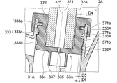
- the holding structure 333 protrudes outward from the outer surface of the wall 332. In a state where the wall portion 332 of the holding member 33 is interposed between the casing 31 and the base portion 32, the holding structure 333 protrudes from the outer surface of the wall portion 332 toward the casing 31.
- the holding structure 333 of the holding member 33 of the present embodiment has a first protrusion 333 a, a second protrusion 333 b, and a third protrusion 333 c.
- the first protrusion 333 a is integrally formed with the wall 332 and extends in the circumferential direction of the wall 332. That is, the first protrusion 333 a is integrally formed with the wall 332, and is provided in a ring shape along the outer surface of the wall 332.
- the second protrusion 333 b is provided at a position away from the first protrusion 333 a in the direction of the axis 338 of the holding member 33.
- the second protrusion 333 b is integrally formed with the wall 332 and extends in the circumferential direction of the wall 332. That is, the second protrusion 333 b is integrally formed with the wall 332, and is provided in a ring shape along the outer surface of the wall 332.
- the third projection 333 c is provided between the first projection 333 a and the second projection 333 b.
- the third protrusion 333 c is integrally formed with the wall 332 and extends in the circumferential direction of the wall 332. That is, the third protrusion 333 c is integrally formed with the wall 332, and is provided in a ring shape along the outer surface of the wall 332.
- each of the first projection 333 a, the second projection 333 b and the third projection 333 c protrudes outward from the outer surface of the wall 332, and rings along the outer surface of the wall 332. It is provided in the form of Therefore, in the state where the base portion 32 is held by the casing 31 via the holding member 33 (the wall portion 332 is interposed between the casing 31 and the base portion 32), the holding member 33 is of the base portion 32. Detachment from the casing 31 along the shaft 325 or the shaft 338 of the holding member 33 can be suppressed.
- the first projection 333 a and the second projection 333 c are provided apart from each other in the direction of the axis 338 of the holding member 33. Therefore, the first projection 333a and the second projection 333c can support the holding of the base 32 with respect to the casing 31 by receiving a force applied from the base 32 to the holding member 33 at a position apart from each other.
- a third projection 333 c is provided between the first projection 333 a and the second projection 333 b. Therefore, even when the force based on the operation of the handle 5 is applied obliquely to the base 32 connected to the handle 5, the force is provided between the first projection 333a and the second projection 333b.
- the sealed third projection 333 c can ensure sealing between the casing 31 and the base 32.
- the third projection 333 c has a holding function of holding the base 32 with respect to the casing 31 and a sealing function of preventing fluid from flowing in the gap between the casing 31 and the base 32.
- the first protrusion 333 a of the present embodiment is in contact with the casing 31 over the entire circumference. Therefore, like the third projection 333c, the first projection 333a has a holding function of holding the base 32 with respect to the casing 31, and that the fluid flows in the gap between the casing 31 and the base 32. And the sealing function to prevent.
- the second projection 333 b of the present embodiment has a portion not in contact with the casing 31 in part. Therefore, the second protrusion 333 b has a holding function of holding the base 32 with respect to the casing 31.
- each of the first protrusion 333 a, the second protrusion 333 b and the third protrusion 333 c is provided in a ring shape along the outer surface of the wall 332, the holding member 33 is the shaft 325 of the base 32 or The resistance received from the casing 31 when the holding member 33 rotates about the shaft 338 is the resistance received from the casing 31 when the holding member 33 moves along the shaft 325 of the base portion 32 or the shaft 338 of the holding member 33. Less than force.
- the holding member 33 is separated from the casing 31 It is possible to rotate about the shaft 325 of the base portion 32 or the shaft 338 of the holding member 33 while being prevented from coming off.
- the handle 5 is rotated with respect to the casing 31 about the axis 325 of the base portion 32 in a state of being held by the casing 31, the base portion 32 provided with the retention member 33 is held together with the handle 5. It can rotate relative to the casing 31.
- Each of the first projection 333 a, the second projection 333 b, and the third projection 333 c is integrally formed with the wall 332. Therefore, in the case where the holding member 33 receives a force along the shaft 325 of the base portion 32 or the shaft 338 of the holding member 33 or rotates around the shaft 325 of the base portion 32 or the shaft 338 of the holding member 33 Also, unlike the O-ring or the like provided as a separate member of the holding member, the first projection 333a, the second projection 333b, and the third projection 333c do not come off the wall 332. Therefore, loss of the first protrusion 333a, the second protrusion 333b, and the third protrusion 333c can be suppressed.
- the base portion 32 has a first support portion 326a, a second support portion 326b, and a third support portion 326c.
- the first support portion 326a is a position corresponding to the first protrusion 333a and opposite to the side where the first protrusion 333a protrudes. It is provided at the side position and protrudes toward the first protrusion 333a.
- the first support portion 326a is opposite to the back side of the first protrusion 333a (the side opposite to the side where the first protrusion 333a protrudes). Side) can be supported.
- the second support portion 326 b is provided at a position corresponding to the second protrusion 333 b and at a position opposite to the side where the second protrusion 333 b protrudes, and protrudes toward the second protrusion 333 b.
- the second support portion 326b is opposite to the back side of the second protrusion 333b (the side opposite to the side where the second protrusion 333b protrudes). Side) can be supported.
- the third support portion 326 c is provided at a position corresponding to the third protrusion 333 c and at a position opposite to the side where the third protrusion 333 c protrudes, and protrudes toward the third protrusion 333 c.
- the third support portion 326c is opposite to the back side of the third projection 333c (the side opposite to the side where the third projection 333c protrudes). Side) can be supported. Thereby, the holding power of the base portion 32 with respect to the casing 31 can be enhanced, and the sealing property between the casing 31 and the base portion 32 can be enhanced.
- the length (projected length of the first support section 326a) D1 in which the first support section 326a protrudes is longer than the length (projected length of the second support section 326b) D2 in which the second support section 326b protrudes.
- the length D2 where the second support portion 326b protrudes is shorter than the length D3 where the third support portion 326c protrudes (protrusion length of the third support portion 326c).
- the protrusion length D1 of the first support portion 326a, the protrusion length D2 of the second support portion 326b, and the protrusion length D3 of the third support portion 326c are different from each other.
- the holding power of the base portion 32 with respect to the casing 31 can be appropriately adjusted, and the holding power can be suppressed from being excessively high. Thereby, the decomposability of the casing 31 and the base portion 32 can be enhanced while maintaining the holding force of the base portion 32 with respect to the casing 31.
- the holding member 33 has a hook portion 336.
- the hook portion 336 is provided on the inner side of the wall portion 332, and is formed as a groove portion which is recessed outward from the inner surface of the wall portion 332. Therefore, as shown in FIG. 5, at least one of the first support portion 326 a, the second support portion 326 b, and the third support portion 326 c is hooked on the hook portion 336. Therefore, even when a relatively strong force is applied to the holding member 33, the holding member 33 can be prevented from being detached from the base portion 32.
- the holding member 33 has a backflow prevention wall 337.
- the backflow prevention wall 337 surrounds the through hole 335 provided in the bottom portion 334 of the holding member 33 and extends outward from the bottom portion 334.
- the through hole 335 spatially connects the internal space S3 and the communication portion S4. Therefore, the backflow prevention wall 337 can suppress that the breast milk is sucked along the wall portion 332 and the bottom portion 334 of the holding member 33 from the through hole 335 toward the communication portion S4. That is, the backflow prevention wall 337 can prevent milked milk from flowing (backflowing) through the through hole 335 toward the communication portion S4.
- the speed at which the handle 5 returns (the moving speed of the handle 5) is, for example, the through hole 335 of the holding member 33. Changes according to the diameter of the Therefore, by adjusting the diameter of the through hole 335 of the holding member 33, it is possible to adjust the moving speed of the handle 5 when the handle 5 returns to the original state. As a result, the feeling of operation of the handle 5 can be improved, and the milking device 2 can be given a high-class feeling.
- the holding member 33A is provided not on the base portion 32A but on the casing 31A.
- the breast pump 2A according to the first modification is different from the breast pump 2 described above with reference to FIGS.
- the holding structure 333 of the present modification protrudes inward from the inner surface of the wall portion 332 of the holding member 33A.
- the holding structure 333 protrudes from the inner surface of the wall portion 332 toward the base portion 32A.
- Each of the first projection 333 a, the second projection 333 b, and the third projection 333 c is integrally formed with the wall 332, and is provided in a ring shape along the inner surface of the wall 332.
- the base portion 32A is the base portion 32A.
- Detachment from the holding member 33A can be suppressed along the shaft 325 or the shaft 338 of the holding member 33A. Thereby, for example, even when the force based on the operation of the handle 5 is applied in an oblique direction to the base portion 32A connected to the handle 5, the base portion 32A can be prevented from being detached from the casing 31A. it can.
- the casing 31A has a first support 371a, a second support 371b, and a third support 371c.
- the first support portion 371a is a position corresponding to the first protrusion 333a and opposite to the side where the first protrusion 333a protrudes. It is provided at the side position and protrudes toward the first protrusion 333a. Therefore, the first support portion 371a can support the first projection 333a from the back side in a state in which the wall portion 332 is interposed between the casing 31A and the base portion 32A.
- the second support portion 371 b is provided at a position corresponding to the second protrusion 333 b and on the opposite side to the side where the second protrusion 333 b protrudes, and protrudes toward the second protrusion 333 b. Therefore, the second support portion 371b can support the second projection 333b from the back side in a state in which the wall portion 332 is interposed between the casing 31A and the base portion 32A.
- the third support 371c is provided at a position corresponding to the third protrusion 333c and on the opposite side to the side where the third protrusion 333c protrudes, and protrudes toward the third protrusion 333c.
- the third support portion 371c can support the third projection 333c from the back side in a state where the wall portion 332 is interposed between the casing 31A and the base portion 32A.
- the holding power of the base portion 32A with respect to the casing 31A can be enhanced, and the hermeticity between the casing 31A and the base portion 32A can be enhanced.
- the length (projected length of the first support section 371a) D4 in which the first support section 371a protrudes is longer than the length (projected length of the second support section 371b) D5 in which the second support section 371b protrudes.
- the length D5 where the second support portion 371b protrudes is shorter than the length (the protrusion length of the third support portion 371c) D6 where the third support portion 371c protrudes.
- the protrusion length D4 of the first support portion 371a, the protrusion length D5 of the second support portion 371b, and the protrusion length D6 of the third support portion 371c are different from each other.
- the holding power of the base portion 32A with respect to the casing 31A can be appropriately adjusted, and the holding power can be suppressed from being excessively high. Thereby, the decomposability of the casing 31A and the base portion 32A can be enhanced while maintaining the holding power of the base portion 32A with respect to the casing 31A.
- the holding member 33A has a hook portion 336A.
- the hook portion 336A is provided on the outer side of the wall portion 332, and is formed as a protrusion protruding from the outer surface of the wall portion 332. Therefore, as shown in FIG. 8, the hook portion 336A is hooked on at least one of the first support portion 371a, the second support portion 371b, and the third support portion 371c. Therefore, even when a relatively strong force is applied to the holding member 33A, the holding member 33A can be prevented from being detached from the casing 31A.
- the holding member 33B is provided not on the base portion 32B but on the casing 31B.
- the breast pump 2B according to the second modification is different from the breast pump 2 described above with reference to FIGS.
- the base portion 32B of this modification is in contact with the holding member 33B not on the inside but on the outside of the holding member 33B, and is held by the casing 31B via the holding member 33B.
- the breast pump 2B according to the second modification is different from the breast pump 2A according to the first modification.
- the holding structure 333 of the present modification protrudes outward from the outer surface of the wall portion 332 of the holding member 33B.
- the holding structure 333 of this modification is similar to the holding structure 333 of the holding member 33 described above with reference to FIGS. 5 to 6B.
- each of the first protrusion 333a, the second protrusion 333b, and the third protrusion 333c is in contact with the inner surface of the base 32B. Therefore, in the state where the base portion 32B is held by the casing 31B via the holding member 33B (the wall portion 332 is sandwiched between the casing 31B and the base portion 32B), the base portion 32B is the base portion 32B.
- Detachment from the holding member 33B can be suppressed along the shaft 325 or the shaft 338 of the holding member 33B. Thereby, for example, even when the force based on the operation of the handle 5 is applied in an oblique direction to the base portion 32B connected to the handle 5, the base portion 32B can be prevented from coming off the casing 31B. it can.
- the casing 31B has a first support portion 372a, a second support 372b, and a third support portion 372c.
- the first support portion 372a In a state where the base portion 32B is held by the casing 31B via the holding member 33B, the first support portion 372a is a position corresponding to the first projection 333a and opposite to the side where the first projection 333a protrudes It is provided at the side position and protrudes toward the first protrusion 333a. Therefore, the first support portion 372a can support the first protrusion 333a from the back side in a state in which the wall portion 332 is interposed between the casing 31B and the base portion 32B.
- the second support portion 372b is provided at a position corresponding to the second protrusion 333b and on the opposite side to the side where the second protrusion 333b protrudes, and protrudes toward the second protrusion 333b. Therefore, the second support portion 372b can support the second projection 333b from the back side in a state in which the wall portion 332 is interposed between the casing 31B and the base portion 32B.
- the third support portion 372c is provided at a position corresponding to the third protrusion 333c and at a position opposite to the side where the third protrusion 333c protrudes, and protrudes toward the third protrusion 333c.
- the third support portion 372c can support the third protrusion 333c from the back side in a state where the wall portion 332 is interposed between the casing 31B and the base portion 32B. Thereby, the holding power of the base portion 32B with respect to the casing 31B can be enhanced, and the hermeticity between the casing 31B and the base portion 32B can be enhanced.
- the length (protrusion length of the first support portion 372a) D7 where the first support portion 372 protrudes is longer than the length (protrusion length of the second support portion 372b) D8 where the second support portion 372b protrudes.
- the length D8 where the second support 372b protrudes is shorter than the length D9 where the third support 372c protrudes (protrusion length of the third support 372c).
- the holding power of the base portion 32B with respect to the casing 31B can be appropriately adjusted, and the holding power can be suppressed from becoming excessively high. Thereby, the decomposability of the casing 31B and the base portion 32B can be enhanced while maintaining the holding power of the base portion 32B with respect to the casing 31B.
- the holding member 33B has a hook portion 336B.
- the hook portion 336 ⁇ / b> B is provided on the inner side of the wall portion 332, and is formed as a protrusion protruding from the inner surface of the wall portion 332. Therefore, as shown in FIG. 9, the hook portion 336B is hooked on at least one of the first support portion 372a, the second support 372b, and the third support portion 372c. Therefore, even when a relatively strong force is applied to the holding member 33B, the holding member 33B can be prevented from coming off the casing 31B.
- the inventor conducted a study to quantitatively evaluate muscle activity. That is, when the muscle fibers exercise, myoelectric potentials are released as action potentials of the muscle fibers. It is generally known that the amplitude of the myoelectric potential changes approximately in proportion to the muscle output. Therefore, muscle activity can be quantitatively evaluated by measuring muscle potential.
- the MP150 system made by BIOPAC Systems was used as a measuring instrument.
- the “sampling rate at measurement” set in the measurement device is 1000 samples / second.
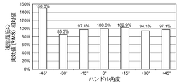
- the handle 5 of the breast pump 2 was gripped to the maximum amount, and then the operation of releasing the handle 5 was repeated twice a second. At this time, by plugging the milking port (the inlet of the food 4), the load equivalent to the actual milking load was reproduced.
- an effective value (RMS value: Root Mean Square value) was determined from an actual measurement value of myoelectric potential measured in 10 seconds.
- the steering wheel angle when the steering wheel angle is 0 °, the actual value is 100%, and the steering wheel angles are -45 °, -30 °, -15 °, + 15 °, + 30 °, + 45 °.
- the value (relative value) was obtained by dividing the effective value of by the reference value.
- the steering wheel angle is 0 °
- the sign of the steering wheel angle is minus (-)
- the state shown in FIG. 3 (b) That is, the steering wheel angle of the steering wheel 5 shown in FIG. 3B is “ ⁇ 45 °”.
- the sign of the steering wheel angle is plus (+)
- the state shown in FIG. 3 (c) That is, the steering wheel angle of the steering wheel 5 shown in FIG. 3C is “+ 45 °”.
- FIG. 10 The example of the result of the examination which this inventor implemented is as having represented to FIG. 10 and FIG. That is, an example of the relationship between the steering wheel angle and the relative value of the effective value of the flexor digitus flexus muscle is as shown in FIG. Also, an example of the relationship between the steering wheel angle and the relative value of the effective value of the total finger extensor muscle is as shown in FIG.
- the flexor digitorum musculature is a type of muscle present in the upper limbs of humans, and functions mainly in the operation of grasping the handle 5 or the like and in the operation of palmar flexion of the wrist joint.
- the extensor digitorum longus is a type of muscle present in the upper extremity of a human, and functions mainly when releasing the handle 5 or the like or when flexing the wrist joint.
Landscapes
- Health & Medical Sciences (AREA)
- Heart & Thoracic Surgery (AREA)
- Biomedical Technology (AREA)
- Vascular Medicine (AREA)
- Engineering & Computer Science (AREA)
- Anesthesiology (AREA)
- Pediatric Medicine (AREA)
- Hematology (AREA)
- Life Sciences & Earth Sciences (AREA)
- Animal Behavior & Ethology (AREA)
- General Health & Medical Sciences (AREA)
- Public Health (AREA)
- Veterinary Medicine (AREA)
- External Artificial Organs (AREA)
Abstract
Description
なお、以下に説明する実施形態は、本発明の好適な具体例であるから、技術的に好ましい種々の限定が付されているが、本発明の範囲は、以下の説明において特に本発明を限定する旨の記載がない限り、これらの態様に限られるものではない。また、各図面中、同様の構成要素には同一の符号を付して詳細な説明は適宜省略する。
を基準値(100%)として、ハンドル角度が-45°、-30°、-15°、+15°、+30°、+45°であるときのそれぞれの実効値を基準値で除した値(相対値)を求めた。
Claims (9)
- 母乳が一時的に貯留される内部空間を有する本体ケーシングと、
前記本体ケーシングに接続され乳房にあてがわれるフードと、
前記本体ケーシングに保持され前記内部空間と空間的に接続された連通部を有するベース部と、
前記ベース部に設けられ前記連通部に負圧を発生させるダイヤフラムと、
前記本体ケーシングおよび前記ベース部のいずれかに設けられ前記本体ケーシングと前記ベース部との間に挟設された壁部を有する保持部材と、
前記ベース部に接続されるとともに前記ベース部の軸を中心として前記本体ケーシングに対して回転可能に設けられ前記ダイヤフラムを変形させる操作用のハンドルと、
を備え、
前記ベース部は、前記ハンドルが前記ベース部の軸を中心として前記本体ケーシングに対して回転すると前記ハンドルとともに前記保持部材を介して前記本体ケーシングに対して回転することを特徴とする手動搾乳器。 - 前記本体ケーシングは、前記ベース部の軸を中心とした前記ベース部の回転の範囲を規制する規制部を有することを特徴とする請求項1に記載の手動搾乳器。
- 前記保持部材は、前記壁部の表面から前記本体ケーシングおよび前記ベース部のいずれかに向かって突出し前記本体ケーシングに対する前記ベース部の保持を支える保持構造を有することを特徴とする請求項1または2に記載の手動搾乳器。
- 前記保持構造は、
前記壁部の周方向に延びた第1突起部と、
前記第1突起部とは離れて設けられ前記壁部の周方向に延びた第2突起部と、
を有することを特徴とする請求項3に記載の手動搾乳器。 - 前記保持構造は、前記第1突起部と前記第2突起部との間に設けられ前記壁部の周方向に延びた第3突起部をさらに有することを特徴とする請求項4に記載の手動搾乳器。
- 前記保持部材が設けられた前記本体ケーシングおよび前記ベース部のいずれかは、
前記第1突起部に対応する位置であって前記第1突起部が突出した側とは反対側の位置に設けられ前記第1突起部に向かって突出した第1支持部と、
前記第2突起部に対応する位置であって前記第2突起部が突出した側とは反対側の位置に設けられ前記第2突起部に向かって突出した第2支持部と、
を有することを特徴とする請求項4または5に記載の手動搾乳器。 - 前記第1支持部および前記第2支持部のいずれか一方が突出した長さは、前記第1支持部および前記第2支持部のいずれか他方が突出した長さよりも長いことを特徴とする請求項6に記載の手動搾乳器。
- 前記保持部材は、前記第1支持部および前記第2支持部の少なくともいずれかに引っ掛かるフック部を有することを特徴とする請求項6または7に記載の手動搾乳器。
- 前記保持部材は、
前記内部空間と前記連通部とを空間的に接続する貫通孔を有する底部と、
前記貫通孔の周りを囲み前記底部から外側に向かって延びた逆流防止壁と、
を有することを特徴とする請求項1~8のいずれか1項に記載の手動搾乳器。
Priority Applications (3)
| Application Number | Priority Date | Filing Date | Title |
|---|---|---|---|
| US16/621,950 US12383661B2 (en) | 2017-06-30 | 2018-06-22 | Manual breast pump |
| EP18823931.3A EP3646902B1 (en) | 2017-06-30 | 2018-06-22 | Manual breast pump |
| CN201880042432.5A CN110785190B (zh) | 2017-06-30 | 2018-06-22 | 手动挤奶器 |
Applications Claiming Priority (2)
| Application Number | Priority Date | Filing Date | Title |
|---|---|---|---|
| JP2017-128897 | 2017-06-30 | ||
| JP2017128897A JP6965043B2 (ja) | 2017-06-30 | 2017-06-30 | 手動搾乳器 |
Publications (1)
| Publication Number | Publication Date |
|---|---|
| WO2019004092A1 true WO2019004092A1 (ja) | 2019-01-03 |
Family
ID=64742249
Family Applications (1)
| Application Number | Title | Priority Date | Filing Date |
|---|---|---|---|
| PCT/JP2018/023869 Ceased WO2019004092A1 (ja) | 2017-06-30 | 2018-06-22 | 手動搾乳器 |
Country Status (5)
| Country | Link |
|---|---|
| US (1) | US12383661B2 (ja) |
| EP (1) | EP3646902B1 (ja) |
| JP (1) | JP6965043B2 (ja) |
| CN (1) | CN110785190B (ja) |
| WO (1) | WO2019004092A1 (ja) |
Cited By (1)
| Publication number | Priority date | Publication date | Assignee | Title |
|---|---|---|---|---|
| CN114650851A (zh) * | 2019-11-14 | 2022-06-21 | 贝亲株式会社 | 吸奶器 |
Families Citing this family (5)
| Publication number | Priority date | Publication date | Assignee | Title |
|---|---|---|---|---|
| JP7133976B2 (ja) * | 2018-05-15 | 2022-09-09 | ピジョン株式会社 | 手動搾乳器 |
| JP7280667B2 (ja) * | 2018-06-05 | 2023-05-24 | ピジョン株式会社 | 搾乳器 |
| JP7343597B2 (ja) * | 2019-09-20 | 2023-09-12 | ピジョン株式会社 | 搾乳器 |
| US20220339330A1 (en) | 2019-09-20 | 2022-10-27 | Pigeon Corporation | Breast pump |
| CN116650743B (zh) * | 2023-07-06 | 2025-07-15 | 浙江新贝医疗器械有限公司 | 一种用于挤出母乳的吸乳器装置 |
Citations (3)
| Publication number | Priority date | Publication date | Assignee | Title |
|---|---|---|---|---|
| US6749582B2 (en) | 2002-04-30 | 2004-06-15 | The First Years Inc. | Pumping breast milk |
| US20050154348A1 (en) * | 2004-01-08 | 2005-07-14 | Daniel Lantz | Breast pump |
| WO2014112078A1 (ja) * | 2013-01-17 | 2014-07-24 | ピジョン株式会社 | 手動搾乳器 |
Family Cites Families (8)
| Publication number | Priority date | Publication date | Assignee | Title |
|---|---|---|---|---|
| JPS63147471A (ja) * | 1986-12-12 | 1988-06-20 | ピジヨン株式会社 | 搾乳器 |
| JPS63252161A (ja) * | 1987-04-09 | 1988-10-19 | ジェクス株式会社 | 搾乳器 |
| WO2007017968A1 (ja) * | 2005-08-09 | 2007-02-15 | Pigeon Corporation | 搾乳器 |
| JP5204533B2 (ja) * | 2008-04-04 | 2013-06-05 | ピジョン株式会社 | 搾乳器 |
| EP2186532A1 (en) * | 2008-11-12 | 2010-05-19 | Ardo medical AG | Breast pump |
| CN201436036U (zh) | 2009-05-31 | 2010-04-07 | 东莞市嘟宝母婴用品有限公司 | 一种结构改良的手持式吸乳器 |
| JP5681554B2 (ja) * | 2011-04-22 | 2015-03-11 | ピジョン株式会社 | 手動搾乳器 |
| JP5726622B2 (ja) * | 2011-04-28 | 2015-06-03 | ピジョン株式会社 | 搾乳器 |
-
2017
- 2017-06-30 JP JP2017128897A patent/JP6965043B2/ja active Active
-
2018
- 2018-06-22 EP EP18823931.3A patent/EP3646902B1/en active Active
- 2018-06-22 WO PCT/JP2018/023869 patent/WO2019004092A1/ja not_active Ceased
- 2018-06-22 CN CN201880042432.5A patent/CN110785190B/zh active Active
- 2018-06-22 US US16/621,950 patent/US12383661B2/en active Active
Patent Citations (3)
| Publication number | Priority date | Publication date | Assignee | Title |
|---|---|---|---|---|
| US6749582B2 (en) | 2002-04-30 | 2004-06-15 | The First Years Inc. | Pumping breast milk |
| US20050154348A1 (en) * | 2004-01-08 | 2005-07-14 | Daniel Lantz | Breast pump |
| WO2014112078A1 (ja) * | 2013-01-17 | 2014-07-24 | ピジョン株式会社 | 手動搾乳器 |
Non-Patent Citations (1)
| Title |
|---|
| See also references of EP3646902A4 |
Cited By (2)
| Publication number | Priority date | Publication date | Assignee | Title |
|---|---|---|---|---|
| CN114650851A (zh) * | 2019-11-14 | 2022-06-21 | 贝亲株式会社 | 吸奶器 |
| EP4059531A4 (en) * | 2019-11-14 | 2023-07-26 | Pigeon Corporation | Milking machine |
Also Published As
| Publication number | Publication date |
|---|---|
| EP3646902A4 (en) | 2021-03-24 |
| EP3646902A1 (en) | 2020-05-06 |
| EP3646902B1 (en) | 2022-09-28 |
| JP2019010350A (ja) | 2019-01-24 |
| JP6965043B2 (ja) | 2021-11-10 |
| CN110785190B (zh) | 2022-11-15 |
| US12383661B2 (en) | 2025-08-12 |
| CN110785190A (zh) | 2020-02-11 |
| US20200171223A1 (en) | 2020-06-04 |
Similar Documents
| Publication | Publication Date | Title |
|---|---|---|
| WO2019004092A1 (ja) | 手動搾乳器 | |
| AU2003241056B2 (en) | Breast pump | |
| EP3647638B1 (en) | Non-return valve | |
| JP5156702B2 (ja) | 搾乳ポンプ組立体用の乳房覆い | |
| AU2006277515B2 (en) | Milking device | |
| CN112272570B (zh) | 吸奶器 | |
| EP2946798B1 (en) | Manual breastpump | |
| US8636158B2 (en) | Dual chamber nursing bottle | |
| CN211485901U (zh) | 吸乳器和喂食套件 | |
| AU2007209746A1 (en) | Attachment for a milk pump | |
| CN112105397B (zh) | 手动吸奶器 | |
| JP2004147781A (ja) | 弁装置及び圧力調整用の弁装置と圧力調整用の弁装置を備える手動搾乳器 | |
| CN114650851B (zh) | 吸奶器 | |
| EP4032566B1 (en) | Breast pump | |
| AU2007214354B2 (en) | Breast pump | |
| KR19980022915U (ko) | 함몰유두 교정구 | |
| HK1243962A1 (zh) | 用於吸乳护罩的具有介质分隔膜的适配器 |
Legal Events
| Date | Code | Title | Description |
|---|---|---|---|
| 121 | Ep: the epo has been informed by wipo that ep was designated in this application |
Ref document number: 18823931 Country of ref document: EP Kind code of ref document: A1 |
|
| NENP | Non-entry into the national phase |
Ref country code: DE |
|
| WWE | Wipo information: entry into national phase |
Ref document number: 2018823931 Country of ref document: EP |
|
| ENP | Entry into the national phase |
Ref document number: 2018823931 Country of ref document: EP Effective date: 20200130 |
|
| WWG | Wipo information: grant in national office |
Ref document number: 16621950 Country of ref document: US |