WO2019013243A1 - 内視鏡用可撓管、内視鏡型医療機器、及びこれらの製造方法 - Google Patents
内視鏡用可撓管、内視鏡型医療機器、及びこれらの製造方法 Download PDFInfo
- Publication number
- WO2019013243A1 WO2019013243A1 PCT/JP2018/026153 JP2018026153W WO2019013243A1 WO 2019013243 A1 WO2019013243 A1 WO 2019013243A1 JP 2018026153 W JP2018026153 W JP 2018026153W WO 2019013243 A1 WO2019013243 A1 WO 2019013243A1
- Authority
- WO
- WIPO (PCT)
- Prior art keywords
- flexible tube
- group
- layer
- endoscope
- resin coating
- Prior art date
- Legal status (The legal status is an assumption and is not a legal conclusion. Google has not performed a legal analysis and makes no representation as to the accuracy of the status listed.)
- Ceased
Links
Images

Classifications
-
- A—HUMAN NECESSITIES
- A61—MEDICAL OR VETERINARY SCIENCE; HYGIENE
- A61B—DIAGNOSIS; SURGERY; IDENTIFICATION
- A61B1/00—Instruments for performing medical examinations of the interior of cavities or tubes of the body by visual or photographical inspection, e.g. endoscopes; Illuminating arrangements therefor
- A61B1/005—Flexible endoscopes
- A61B1/0051—Flexible endoscopes with controlled bending of insertion part
-
- C—CHEMISTRY; METALLURGY
- C09—DYES; PAINTS; POLISHES; NATURAL RESINS; ADHESIVES; COMPOSITIONS NOT OTHERWISE PROVIDED FOR; APPLICATIONS OF MATERIALS NOT OTHERWISE PROVIDED FOR
- C09J—ADHESIVES; NON-MECHANICAL ASPECTS OF ADHESIVE PROCESSES IN GENERAL; ADHESIVE PROCESSES NOT PROVIDED FOR ELSEWHERE; USE OF MATERIALS AS ADHESIVES
- C09J175/00—Adhesives based on polyureas or polyurethanes; Adhesives based on derivatives of such polymers
- C09J175/04—Polyurethanes
- C09J175/06—Polyurethanes from polyesters
-
- A—HUMAN NECESSITIES
- A61—MEDICAL OR VETERINARY SCIENCE; HYGIENE
- A61B—DIAGNOSIS; SURGERY; IDENTIFICATION
- A61B1/00—Instruments for performing medical examinations of the interior of cavities or tubes of the body by visual or photographical inspection, e.g. endoscopes; Illuminating arrangements therefor
- A61B1/00064—Constructional details of the endoscope body
- A61B1/00071—Insertion part of the endoscope body
-
- A—HUMAN NECESSITIES
- A61—MEDICAL OR VETERINARY SCIENCE; HYGIENE
- A61B—DIAGNOSIS; SURGERY; IDENTIFICATION
- A61B1/00—Instruments for performing medical examinations of the interior of cavities or tubes of the body by visual or photographical inspection, e.g. endoscopes; Illuminating arrangements therefor
- A61B1/00064—Constructional details of the endoscope body
- A61B1/0011—Manufacturing of endoscope parts
-
- A—HUMAN NECESSITIES
- A61—MEDICAL OR VETERINARY SCIENCE; HYGIENE
- A61B—DIAGNOSIS; SURGERY; IDENTIFICATION
- A61B1/00—Instruments for performing medical examinations of the interior of cavities or tubes of the body by visual or photographical inspection, e.g. endoscopes; Illuminating arrangements therefor
- A61B1/005—Flexible endoscopes
- A61B1/0051—Flexible endoscopes with controlled bending of insertion part
- A61B1/0055—Constructional details of insertion parts, e.g. vertebral elements
-
- B—PERFORMING OPERATIONS; TRANSPORTING
- B32—LAYERED PRODUCTS
- B32B—LAYERED PRODUCTS, i.e. PRODUCTS BUILT-UP OF STRATA OF FLAT OR NON-FLAT, e.g. CELLULAR OR HONEYCOMB, FORM
- B32B1/00—Layered products having a non-planar shape
- B32B1/08—Tubular products
-
- B—PERFORMING OPERATIONS; TRANSPORTING
- B32—LAYERED PRODUCTS
- B32B—LAYERED PRODUCTS, i.e. PRODUCTS BUILT-UP OF STRATA OF FLAT OR NON-FLAT, e.g. CELLULAR OR HONEYCOMB, FORM
- B32B15/00—Layered products comprising a layer of metal
- B32B15/04—Layered products comprising a layer of metal comprising metal as the main or only constituent of a layer, which is next to another layer of the same or of a different material
- B32B15/08—Layered products comprising a layer of metal comprising metal as the main or only constituent of a layer, which is next to another layer of the same or of a different material of synthetic resin
- B32B15/095—Layered products comprising a layer of metal comprising metal as the main or only constituent of a layer, which is next to another layer of the same or of a different material of synthetic resin comprising polyurethanes
-
- B—PERFORMING OPERATIONS; TRANSPORTING
- B32—LAYERED PRODUCTS
- B32B—LAYERED PRODUCTS, i.e. PRODUCTS BUILT-UP OF STRATA OF FLAT OR NON-FLAT, e.g. CELLULAR OR HONEYCOMB, FORM
- B32B15/00—Layered products comprising a layer of metal
- B32B15/18—Layered products comprising a layer of metal comprising iron or steel
-
- B—PERFORMING OPERATIONS; TRANSPORTING
- B32—LAYERED PRODUCTS
- B32B—LAYERED PRODUCTS, i.e. PRODUCTS BUILT-UP OF STRATA OF FLAT OR NON-FLAT, e.g. CELLULAR OR HONEYCOMB, FORM
- B32B27/00—Layered products comprising a layer of synthetic resin
- B32B27/40—Layered products comprising a layer of synthetic resin comprising polyurethanes
-
- B—PERFORMING OPERATIONS; TRANSPORTING
- B32—LAYERED PRODUCTS
- B32B—LAYERED PRODUCTS, i.e. PRODUCTS BUILT-UP OF STRATA OF FLAT OR NON-FLAT, e.g. CELLULAR OR HONEYCOMB, FORM
- B32B3/00—Layered products comprising a layer with external or internal discontinuities or unevennesses, or a layer of non-planar shape; Layered products comprising a layer having particular features of form
- B32B3/26—Layered products comprising a layer with external or internal discontinuities or unevennesses, or a layer of non-planar shape; Layered products comprising a layer having particular features of form characterised by a particular shape of the outline of the cross-section of a continuous layer; characterised by a layer with cavities or internal voids ; characterised by an apertured layer
- B32B3/263—Layered products comprising a layer with external or internal discontinuities or unevennesses, or a layer of non-planar shape; Layered products comprising a layer having particular features of form characterised by a particular shape of the outline of the cross-section of a continuous layer; characterised by a layer with cavities or internal voids ; characterised by an apertured layer characterised by a layer having non-uniform thickness
-
- C—CHEMISTRY; METALLURGY
- C08—ORGANIC MACROMOLECULAR COMPOUNDS; THEIR PREPARATION OR CHEMICAL WORKING-UP; COMPOSITIONS BASED THEREON
- C08K—Use of inorganic or non-macromolecular organic substances as compounding ingredients
- C08K5/00—Use of organic ingredients
- C08K5/54—Silicon-containing compounds
- C08K5/541—Silicon-containing compounds containing oxygen
- C08K5/5415—Silicon-containing compounds containing oxygen containing at least one Si—O bond
-
- C—CHEMISTRY; METALLURGY
- C08—ORGANIC MACROMOLECULAR COMPOUNDS; THEIR PREPARATION OR CHEMICAL WORKING-UP; COMPOSITIONS BASED THEREON
- C08K—Use of inorganic or non-macromolecular organic substances as compounding ingredients
- C08K5/00—Use of organic ingredients
- C08K5/54—Silicon-containing compounds
- C08K5/544—Silicon-containing compounds containing nitrogen
-
- C—CHEMISTRY; METALLURGY
- C08—ORGANIC MACROMOLECULAR COMPOUNDS; THEIR PREPARATION OR CHEMICAL WORKING-UP; COMPOSITIONS BASED THEREON
- C08L—COMPOSITIONS OF MACROMOLECULAR COMPOUNDS
- C08L75/00—Compositions of polyureas or polyurethanes; Compositions of derivatives of such polymers
- C08L75/04—Polyurethanes
-
- G—PHYSICS
- G02—OPTICS
- G02B—OPTICAL ELEMENTS, SYSTEMS OR APPARATUS
- G02B23/00—Telescopes, e.g. binoculars; Periscopes; Instruments for viewing the inside of hollow bodies; Viewfinders; Optical aiming or sighting devices
- G02B23/24—Instruments or systems for viewing the inside of hollow bodies, e.g. fibrescopes
-
- B—PERFORMING OPERATIONS; TRANSPORTING
- B32—LAYERED PRODUCTS
- B32B—LAYERED PRODUCTS, i.e. PRODUCTS BUILT-UP OF STRATA OF FLAT OR NON-FLAT, e.g. CELLULAR OR HONEYCOMB, FORM
- B32B2255/00—Coating on the layer surface
- B32B2255/24—Organic non-macromolecular coating
-
- B—PERFORMING OPERATIONS; TRANSPORTING
- B32—LAYERED PRODUCTS
- B32B—LAYERED PRODUCTS, i.e. PRODUCTS BUILT-UP OF STRATA OF FLAT OR NON-FLAT, e.g. CELLULAR OR HONEYCOMB, FORM
- B32B2274/00—Thermoplastic elastomer material
-
- B—PERFORMING OPERATIONS; TRANSPORTING
- B32—LAYERED PRODUCTS
- B32B—LAYERED PRODUCTS, i.e. PRODUCTS BUILT-UP OF STRATA OF FLAT OR NON-FLAT, e.g. CELLULAR OR HONEYCOMB, FORM
- B32B2535/00—Medical equipment, e.g. bandage, prostheses or catheter
-
- B—PERFORMING OPERATIONS; TRANSPORTING
- B32—LAYERED PRODUCTS
- B32B—LAYERED PRODUCTS, i.e. PRODUCTS BUILT-UP OF STRATA OF FLAT OR NON-FLAT, e.g. CELLULAR OR HONEYCOMB, FORM
- B32B2597/00—Tubular articles, e.g. hoses, pipes
Definitions
- the present invention relates to an endoscope flexible tube, an endoscope type medical device, and a method of manufacturing them.
- An endoscope is a medical device for observing a patient's body cavity. Since it is inserted into a body cavity and used, it is desired that the organ should not be injured and cause no pain or discomfort to the patient. From such a demand, the flexible tube constituting the insertion portion of the endoscope (the structure portion to be inserted into the body cavity) adopts a helical tube formed by spirally winding a soft and bendable metal strip. It is done. Furthermore, the periphery of the helical tube is coated with a soft resin, and this resin coating layer is coated with a top coat layer if necessary, so as not to irritate or damage the surface of the body cavity such as the esophagus and intestine.
- the above-mentioned resin coating layer can be formed, for example, by extruding a resin on the outer peripheral surface of a flexible tube base material in which a spiral tube is covered with a tubular net.
- the distal end side be soft to facilitate insertion into a body cavity, and the rear end side be hard to facilitate operation.
- Patent Document 1 discloses that a silane coupling agent exhibiting adhesion to both inorganic substances and organic substances is disposed between a flexible tube base and a resin coating layer.
- the flexible tube in order to smoothly move the flexible tube in a body cavity, the flexible tube is required to have high elasticity.
- the flexible tube that has passed through the bend in the body cavity can easily return to a straight line, and the burden on the subject at the time of examination can be further reduced.
- the present invention is a flexible tube for an endoscope, which is excellent in adhesion between a flexible tube base material and a resin coating layer covering the flexible tube base material and which is also excellent in elasticity, and the flexible tube for an endoscope.
- An object of the present invention is to provide an endoscope type medical device.
- Another object of the present invention is to provide a method of manufacturing the above-mentioned flexible tube for an endoscope and a method of manufacturing the above-mentioned endoscope type medical device.
- the present inventors conducted silane coupling of a specific structure having an amino group on the surface of a flexible tube base composed of a metal material.
- a flexible tube obtained by forming a primer layer containing a curing agent and further employing a polyurethane elastomer as a constituent material of a resin coating layer in contact with the primer layer, adhesion between the flexible tube substrate and the resin coating layer It has been found that the flexibility can be increased to a desired sufficient level, and that this flexible tube is also excellent in elasticity.
- the present invention has been further studied based on these findings and has been completed.
- a flexible tube for an endoscope comprising: a flexible tube base made of metal and a resin coating layer covering an outer periphery of the flexible tube base, A primer layer containing a compound represented by the following general formula (1) is provided between the flexible tube substrate and the resin coating layer, and the resin coating layer has a polyurethane elastomer at least on the side in contact with the primer layer.
- Flexible tube for endoscopes comprising: a flexible tube base made of metal and a resin coating layer covering an outer periphery of the flexible tube base, A primer layer containing a compound represented by the following general formula (1) is provided between the flexible tube substrate and the resin coating layer, and the resin coating layer has a polyurethane elastomer at least on the side in contact with the primer layer.
- X 1 and X 2 each represent a hydrogen atom, an alkyl group, a cycloalkyl group, an alkenyl group, an aryl group, an acyl group, an alkoxycarbonyl group or a carbamoyl group.
- Y 1 represents a hydroxy group or an alkoxy group.
- Y 2 and Y 3 represent a hydroxy group, an alkoxy group or an alkyl group.
- L represents a single bond or a divalent group selected from an alkylene group, an arylene group and -O-, or a divalent group formed by combining two or more of these divalent groups.
- the resin coating layer has a two-layer structure, and the ratio of the thickness of the inner layer and the outer layer of the two-layer structure changes in an inclined manner in the axial direction of the flexible tube base material, [1] to [4]
- the flexible tube for an endoscope according to any one of the above.
- An endoscope type medical device having the flexible tube for an endoscope according to any one of [1] to [6].
- a step of forming a primer layer containing a compound represented by the following general formula (1) on at least the outer periphery of a flexible tube base made of metal, and the above formed on the outer periphery of the flexible tube base A method for producing a flexible tube for an endoscope, comprising the step of forming a resin coating layer by coating a resin containing a polyurethane elastomer in contact with a primer layer.
- X 1 and X 2 each represent a hydrogen atom, an alkyl group, a cycloalkyl group, an alkenyl group, an aryl group, an acyl group, an alkoxycarbonyl group or a carbamoyl group.
- Y 1 represents a hydroxy group or an alkoxy group.
- Y 2 and Y 3 represent a hydroxy group, an alkoxy group or an alkyl group.
- L represents a single bond or a divalent group selected from an alkylene group, an arylene group and -O-, or a divalent group formed by combining two or more of these divalent groups.
- the resin coating layer has a two-layer structure, and at least the inner layer of the two-layer structure includes a polyurethane elastomer, and the ratio of the thickness of the inner layer and the outer layer of the two-layer structure is inclined in the axial direction of the flexible tube base [8]
- the method for producing a flexible tube for an endoscope according to [8].
- substituents and the like when there are a plurality of substituents, linking groups and the like (hereinafter referred to as substituents and the like) indicated by specific symbols, or when a plurality of substituents and the like are defined simultaneously or alternatively,
- the substituents and the like mean that they may be the same or different. Also, even if not particularly mentioned, it means that when a plurality of substituents and the like are adjacent to each other, they may be linked to each other or condensed to form a ring.
- substituent which does not specify substitution or non-substitution the same applies to a linking group
- this carbon number means the carbon number of the whole group. That is, when this group is in a form further having a substituent, it means the total number of carbons including this substituent.
- the flexible tube for an endoscope of the present invention is excellent in the adhesion between the flexible tube base material and the resin coating layer covering the flexible tube base material, and is also excellent in the elasticity.
- the flexible tube which is a structural portion inserted into the body cavity, has excellent adhesion between the flexible tube base and the resin coating layer that covers it, and it is resilient. Also excellent. Therefore, the endoscope-type medical device of the present invention can further reduce the burden on the subject during use.
- the flexible tube for an endoscope is excellent in the adhesion between the flexible tube base material and the resin coating layer covering the flexible tube base material and also has excellent elasticity.
- the flexible tube constituting the device has excellent adhesion between the flexible tube base material and the resin coating layer covering the flexible tube base material. It is also possible to increase the elasticity of this flexible tube. Therefore, according to the method for manufacturing an endoscope-type medical device of the present invention, an endoscope-type medical device in which the burden on the subject during use is further reduced can be obtained.
- BRIEF DESCRIPTION OF THE DRAWINGS It is an external view which shows the structure of one Embodiment of an electronic endoscope.
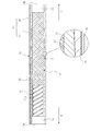
- BRIEF DESCRIPTION OF THE DRAWINGS It is a fragmentary sectional view which shows the structure of one Embodiment of the flexible tube for endoscopes.
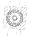
- FIG. 4 is a cross-sectional view taken along the line BB of FIG. 3;
- the electronic endoscope incorporates an endoscope flexible tube (hereinafter, the endoscope flexible tube may be simply referred to as "flexible tube”), and the flexible tube is inserted into a body cavity. It is used as a medical device for observing body cavities.
- the electronic endoscope 2 includes an insertion unit 3 inserted into a body cavity, a main body operation unit 5 continuously provided at a proximal end portion of the insertion unit 3, a processor device, and a light source device. And a universal cord 6 to be connected.
- the insertion unit 3 is connected to the flexible tube 3a connected to the main body operation unit 5, the angle part 3b connected to the flexible tube 3a, and the distal end thereof, and an imaging device (not shown) for body cavity imaging And a tip 3c in which the The flexible tube 3a which occupies most of the length of the insertion portion 3 has flexibility over almost the entire length thereof, and in particular, a portion to be inserted inside the body cavity etc. has a more flexible structure.
- the flexible tube has a flexible tube base made of metal as the innermost layer.
- the flexible tube base 14 is a tubular mesh formed by braiding a metal wire on a spiral tube 11 formed by spirally winding a metal strip 11 a on the innermost side. It is preferable to make the form which coat
- the metal constituting the flexible tube base 14 is preferably passivated on its surface in order to prevent corrosion. That is, it is preferable that the flexible tube base 14 have a passive film on the outer periphery thereof. This passivation process can be performed by a conventional method.
- the metal surface may be immersed in a solution containing a strong oxidizing agent such as nitric acid, heated in air (oxygen) or water (steam), or anodized in a solution containing an oxidizing agent.
- a strong oxidizing agent such as nitric acid
- heated in air (oxygen) or water (steam) or anodized in a solution containing an oxidizing agent.
- the metal constituting the flexible tube base 14 is preferably stainless steel.
- the stainless steel surface is usually in a state where chromium and oxygen are combined to form a passive film.
- the above-described passivation treatment is applied to the stainless steel in order to form a more uniform passive film more reliably over the entire stainless steel surface. It is preferable to apply
- a primer layer (not shown) is provided on the outer periphery of the flexible tube base material.
- this primer layer contains a compound represented by the following general formula (1).
- X 1 and X 2 each represent a hydrogen atom, an alkyl group, a cycloalkyl group, an alkenyl group, an aryl group, an acyl group, an alkoxycarbonyl group or a carbamoyl group.
- the alkyl group which can be taken as X 1 and X 2 may be linear or branched.
- the carbon number of the alkyl group is preferably an integer of 1 to 20, more preferably 1 to 15, still more preferably 1 to 10, and particularly preferably 1 to 8.
- Specific examples of the alkyl group that can be taken as X 1 and X 2 include, for example, methyl, ethyl, n-propyl, isopropyl, n-butyl, s-butyl, isobutyl, t-butyl, n-pentyl, n-hexyl, n Mention may be made of heptyl and n-octyl.
- the cycloalkyl group which can be taken as X 1 and X 2 preferably has 3 to 20 carbon atoms, more preferably 3 to 15 carbon atoms, still more preferably 3 to 10 carbon atoms, and particularly preferably 3 to 8 carbon atoms.
- Examples of cycloalkyl groups that can be taken as X 1 and X 2 include, for example, cyclopentyl and cyclohexyl.
- the alkenyl group which can be taken as X 1 and X 2 may be linear or branched.
- the carbon number of the alkenyl group is preferably an integer of 2 to 20, more preferably 2 to 15, still more preferably 2 to 10, and particularly preferably 2 to 5.
- the carbon number of the aryl group that can be taken as X 1 and X 2 is preferably an integer of 6 to 20, more preferably 6 to 15, still more preferably 6 to 12, and particularly preferably 6 to 10.
- Specific examples of aryl groups that can be taken as X 1 and X 2 include, for example, phenyl and naphthyl, with phenyl being preferred.
- the acyl group which can be taken as X 1 and X 2 is preferably an integer of 2 to 40 carbon atoms, more preferably 2 to 30, still more preferably 2 to 20, and particularly preferably 2 to 15.
- an acyl group includes an alkylcarbonyl group and an arylcarbonyl group.
- the alkoxycarbonyl group which can be taken as X 1 and X 2 is preferably an integer of 2 to 40 carbon atoms, more preferably 2 to 30, still more preferably 2 to 20, and particularly preferably 2 to 15.
- the carbamoyl group that can be taken as X 1 and X 2 is preferably an integer having 1 to 40 carbon atoms, more preferably 1 to 30, still more preferably 1 to 20, and particularly preferably 1 to 15.
- an amino group (preferably a nitrogen atom) is preferably contained in the substituent And more preferably an unsubstituted amino group), a hydroxy group, and / or a silyl group (preferably a silyl group having a substituent), and the entire substituent in this substituted silyl group is an amino group having a hydrogen atom bonded to
- the carbon number of (all three substituents when the silyl group has 3 substituents) preferably has 1 to 10, more preferably 1 to 6.
- a silyl group having at least one alkoxy group as a substituent is preferred. Is preferably contained (ie, in the above-mentioned substituents, the above-mentioned amino group, above-mentioned hydroxy group, and above-mentioned silyl group Preferably, at least one is included.).
- this substituent is preferably an amino group (preferably nitrogen It is an amino group having a hydrogen atom bonded to an atom, more preferably an unsubstituted amino group, a hydroxy group or a silyl group (preferably a silyl group having a substituent), and the entire substituent in this substituted silyl group (silyl
- the carbon number of all three substituents is preferably 1 to 10, more preferably 1 to 6.
- a silyl group having at least one alkoxy group as a substituent is preferable. Is also preferred.
- X 1 and X 2 may be linked to each other to form a ring.
- the number of atoms constituting the ring is preferably 3 to 10, more preferably 4 to 8, and most preferably 5 or 6.
- a ring which can be formed by connecting X 1 and X 2 to each other usually contains a carbon atom as a ring constituting atom in addition to a nitrogen atom, and may have a hetero atom other than a nitrogen atom.
- a hetero atom other than a nitrogen atom an oxygen atom, a sulfur atom, and a silicon atom can be mentioned, for example.
- Both X 1 and X 2 are preferably hydrogen atoms. It is also preferable that one of X 1 and X 2 is a hydrogen atom, and the other is an alkyl group having an amino group.
- Y 1 represents a hydroxy group or an alkoxy group, preferably an alkoxy group.
- an alkyl group which comprises an alkoxy group which can be taken as Y 1 the alkyl group which can be taken as said X 1 and X 2 can be mentioned, The preferable form of the alkyl group which can be taken as X 1 and X 2 It is the same.
- Y 2 and Y 3 represent a hydroxy group, an alkoxy group or an alkyl group.
- the alkoxy group that can be taken as Y 2 and Y 3 is the same as the alkoxy group that can be taken as Y 1 , and the preferred embodiments are also the same.
- the alkyl group can take as Y 2 and Y 3, has the same meaning as the alkyl group which may take as X 1 and X 2 above, a preferred form also the same.
- At least one of Y 1 , Y 2 and Y 3 is preferably an alkoxy group, more preferably at least two are alkoxy groups, and all of Y 1 , Y 2 and Y 3 are alkoxy groups Is more preferred.
- X 2 and Y 3 may be linked to each other to form a ring.
- the number of atoms constituting the ring is preferably 3 to 10, more preferably 4 to 8, and most preferably 5 or 6.
- L described later is preferably a single bond.
- a ring-constituting atom other than a nitrogen atom and a silicon atom is a carbon atom.
- L is a single bond or a divalent group selected from an alkylene group, an arylene group and -O- (ether bond), or a divalent group selected from an alkylene group, an arylene group and -O- It is a divalent group formed by combining the groups of When L is a divalent group, the molecular weight of L is preferably 14 to 300, and more preferably 14 to 210.
- the alkylene group which can constitute L may be linear or branched.
- the carbon number of the alkylene group is preferably an integer of 1 to 20, more preferably 1 to 15, still more preferably 1 to 12, and still more preferably 1 to 8.
- the arylene group which can constitute L preferably has a carbon number of 6 to 20, preferably 6 to 15, more preferably 6 to 12, and particularly preferably 6 to 10.
- the arylene group which can constitute L is particularly preferably phenylene.
- L is preferably an alkylene group, more preferably a linear alkylene group.
- the carbon number of this linear alkylene group is preferably an integer of 1 to 12, more preferably 1 to 6.
- the compound of the said General formula (1) which comprises a primer layer functions as a silane coupling agent. That is, “-Si (Y 1 ) (Y 2 ) Y 3 ” in the general formula (1) interacts with the metal constituting the flexible tube base material, and “-N (X 1 ) X 2 ” is It is thought that the resin coating layer which covers the outer periphery of a flexible tube base material can be firmly stuck on the flexible tube base material surface by interacting with the polyurethane elastomer which constitutes a resin coating layer.
- the interaction of “-Si (Y 1 ) (Y 2 ) Y 3 ” with the metal constituting the flexible tube base 14 is, for example, hydroxy formed by hydrolysis of the alkoxy group possessed by the Si atom of this group.
- the condensation polymerization reaction between the hydroxyl group of the group or Si atom and the hydroxyl group of the flexible tube base metal surface can be mentioned.
- This adhesive layer is a soft layer having a certain thickness.
- the compound of the general formula (1) used in the present invention is a single molecule and contributes to the adhesion between the flexible tube base and the resin coating layer, and the layer thickness of the primer layer is a normal adhesive Much thinner than layers (in other words, the concept of thickness can not be recalled). That is, the primer layer containing the compound of the general formula (1) is different from the adhesive layer which requires a certain layer thickness and softness for the adhesion between the flexible tube substrate and the resin coating layer. Therefore, the primer layer has virtually no influence on the elasticity of the flexible tube, and the flexible tube of the present invention is also excellent in elasticity.
- the flexible tube of the present invention has a resin coating layer on the outer periphery of a flexible tube base provided with a primer layer.
- the outer surface of the resin coating layer 15 is coated with a top coat layer 16 containing fluorine and the like which contributes to chemical resistance and the like.
- a top coat layer 16 containing fluorine and the like which contributes to chemical resistance and the like.
- the resin coating layer covers the outer peripheral surface of the flexible tube substrate having the above-described primer layer.
- the resin coating layer 15 is formed by laminating an inner layer 17 covering the entire peripheral surface around the axis of the flexible tube base 14 and an outer layer 18 covering the entire peripheral surface around the axis of the inner layer 17. It has a two-layer configuration. Usually, a soft resin is used as the material of the inner layer 17 and a hard resin is used as the material of the outer layer 18, but the present invention is not limited to these forms.
- the resin coating layer has a multilayer structure of two or more layers, at least the innermost layer (layer in contact with the primer layer) contains a polyurethane elastomer.
- the single layer resin coating layer contains a polyurethane elastomer. That is, in the present invention, the resin coating layer contains a polyurethane elastomer at least on the side in contact with the primer layer.
- Polyurethane elastomer As a polyurethane elastomer used for a resin coating layer, the usual polyurethane elastomer applicable to formation of a flexible tube can be adopted. This polyurethane elastomer is usually obtained by reacting a polyisocyanate, a polyol and a chain extender.
- the polyurethane elastomer is preferably a block copolymer comprising a soft segment formed by the reaction of a polyol and a polyisocyanate, and a hard segment formed by the reaction of a chain extender and a polyisocyanate.
- polyisocyanate examples include diphenylmethane diisocyanate, hexamethylene diisocyanate, tolidine diisocyanate, 1,5-naphthalene diisocyanate, isophorone diisocyanate, xylylene diisocyanate and the like.
- diphenylmethane diisocyanate and hexamethylene diisocyanate is preferable in terms of abrasion resistance
- isophorone diisocyanate is preferable in terms of disinfectant resistance.
- polyester polyol examples include polytetramethylene ether glycol, polyester polyol, lactone polyester polyol and the like.
- Polyester polyols are obtained by the polycondensation reaction of dicarboxylic acids and diols.
- diol used for producing the polyester polyol include ethanediol, 1,3-propanediol, 1,4-butanediol, 1,5-pentanediol, 1,6-hexanediol and the like. Or in combination.
- dicarboxylic acids include adipic acid, sebacic acid and the like, and these may be used alone or in combination.
- polytetramethylene ether glycol is preferred from the viewpoint of obtaining high resilience.
- chain extender examples include aliphatic linear diols having 2 to 6 carbon atoms such as ethanediol, 1,4-butanediol and 1,6-hexanediol, and 1,4-bis (hydroxyethoxy). Benzene and the like can be mentioned. Amines such as hexamethylene diamine, isophorone diamine, tolylene diamine, monoethanolamine and the like can be used in combination as necessary. Among them, aliphatic straight chain diols having 2 to 6 carbon atoms are preferable from the viewpoint of scratch resistance. As the polyurethane elastomer according to the above embodiment, for example, the disclosure of JP-A-2005-015643 can be referred to.
- the polyurethane elastomer used in the present invention preferably has a polyester structure from the viewpoint of further enhancing the elasticity.
- the said polyurethane elastomer may be used individually by 1 type, and may be used in combination of 2 or more type.
- the content of the polyurethane elastomer in the resin coating layer when the resin coating layer is a single layer, and the content of the polyurethane elastomer in the innermost layer in the case where the resin coating layer is a multilayer are 50% by mass or more More preferably, it is 70 mass% or more, More preferably, it is 80 mass% or more, More preferably, it is 90 mass% or more.
- the resin coating layer in the case where the resin coating layer is a single layer may be a layer made of polyurethane elastomer
- the innermost layer in the case where the resin coating layer is a multilayer is a layer made of polyurethane elastomer Good.
- the resin coating layer in the case where the resin coating layer is a single layer and the innermost layer in the case where the resin coating layer is a multilayer include resins other than polyurethane elastomer, this resin is not particularly limited as long as the effects of the present invention are not impaired. There is no. For example, polyester elastomers and polyamide elastomers can be mentioned.
- polyester elastomers conventional polyester elastomers applicable to the formation of flexible tubes can be used. That is, the polyester elastomer used in the present invention is a copolymer composed of a hard segment consisting of crystalline polyester and a soft segment consisting of polyether or polyester. Examples of hard segments include polybutylene terephthalate and polyethylene terephthalate. Examples of the soft segment include polyalkylene glycols such as polytetramethylene glycol and polypropylene glycol, bisphenol A ethylene oxide adducts, bisphenol A propylene oxide adducts, and polyesters such as polycaprolactone. In the present invention, the "polyester elastomer” preferably contains no urethane bond and no amide bond in the molecule. A polyester elastomer may be used individually by 1 type, and may be used in combination of 2 or more type.
- the above-mentioned polyamide elastomer can also be used the usual polyamide elastomer applicable to formation of a flexible tube.
- the polyamide elastomer preferably does not have a urethane bond.
- the polyamide elastomer may be used alone or in combination of two or more.
- layers other than the innermost layer in the case where the resin coating layer is a multilayer include at least one of a polyurethane elastomer, a polyamide elastomer and a polyester elastomer. These resins can be appropriately combined to form a layer having desired physical properties.
- Layers other than the innermost layer in the case where the resin-coated layer is a multilayer layer more preferably contain a polyurethane elastomer, or contain an alloy of a polyurethane elastomer and a polyester elastomer, from the viewpoint of enhancing the elasticity.
- the above-mentioned respective elastomers which can be used for the resin coating layer of the present invention preferably have a molecular weight of 10,000 to 1,000,000, more preferably 20,000 to 500,000, and particularly preferably 30,000 to 300,000.
- the molecular weight of the elastomer means weight average molecular weight unless otherwise specified.
- the weight average molecular weight can be measured as a polystyrene-equivalent molecular weight by GPC.
- GPC equipment HLC-8220 (trade name, manufactured by Tosoh Corporation) is used, and as an eluent, chloroform is used for polyester elastomer, NMP (N-methyl-2-pyrrolidone) for polyurethane elastomer, and polyamide elastomer.
- m-cresol / chloroform manufactured by Shonan Wako Pure Chemical Industries, Ltd.
- the column is G3000HXL + G2000HXL (all trade names are manufactured by Tosoh Corporation), and detection is performed by RI at 23 ° C. at a flow rate of 1 mL / min. .
- the resin coating layer 15 is preferably formed with a substantially uniform thickness in the longitudinal direction (axial direction) of the flexible tube base 14.
- the thickness of the resin coating layer 15 is, for example, 0.2 mm to 1.0 mm, and the outer diameter D of the flexible tube 3a is, for example, 11 to 14 mm.
- the thicknesses of the inner layer 17 and the outer layer 18 are formed such that the ratio of the thickness of each of the layers 17 and 18 with respect to the entire thickness of the resin coating layer 15 changes in the axial direction of the flexible tube base 14. ing.
- the thickness of the inner layer 17 is greater than the thickness of the outer layer 18 with respect to the total thickness of the resin coating layer 15 on one end 14 a side (tip end side) of the flexible tube base 14 attached to the angle portion 3 b Too big. Then, the thickness of the inner layer 17 gradually decreases from the one end 14 a toward the other end 14 b side (base end side) attached to the main body operation unit 5, and the thickness of the outer layer 18 is the inner layer 17 on the other end 14 b side. It is larger than the thickness of.
- the ratio of the thickness of the inner layer 17 at one end 14a is the largest, and the ratio of the thickness of the outer layer 18 is the largest at the other end 14b.
- Thickness of the inner layer 17 The thickness of the outer layer 18 can be, for example, 9: 1 at one end 14a and, for example, 1: 9 at the other end 14b.
- the thickness of both layers is changed so that the ratio of the thickness of the inner layer 17 to the thickness of the outer layer 18 is reversed from both ends 14a to 14b.
- the hardness of the flexible tube 3a differs between the hardness at the one end 14a and the other end 14b, and the flexibility in the axial direction can be changed so that the one end 14a is soft and the other end 14b is hard.
- the ratio of thickness at one end is preferably 5:95 to 40:60 (inner layer: outer layer), and the ratio of thickness at the other end is 95: 5 to 60:40 (inner layer: outer layer) It is preferable to do.
- the thickness ratio of the inner layer 17 to the outer layer 18 in the range of 5:95 to 95: 5, it is possible to precisely control the extrusion amount of the thinner resin.
- the soft resin and hard resin used for the inner layer 17 and the outer layer 18 preferably have a difference in 100% modulus value, which is an index indicating hardness after molding, to 1 MPa or more, and more preferably 3 MPa or more.
- the difference in melt viscosity at a molding temperature of 150 ° C. to 300 ° C., which is an index representing the fluidity of the molten resin, is preferably 2500 Pa ⁇ s or less.
- top coat layer 16 is disposed on the outer periphery of the resin coating layer 15 as necessary.
- the material of the top coat layer is not particularly limited, but urethane paint, acrylic paint, fluorine paint, silicone paint, epoxy paint, polyester paint and the like are applied.
- the main purpose of using the topcoat layer is to protect and polish the surface of the flexible tube, to impart slipperiness, and to impart chemical resistance. Therefore, it is preferable that the top coat layer has a high elastic modulus and a smooth surface and is excellent in chemical resistance.
- a primer layer is first formed on the flexible tube substrate.
- the primer layer is prepared by dissolving the compound represented by the above general formula (1) in a solvent to prepare a coating solution, and coating or spraying this coating solution on the outer periphery of the flexible tube substrate.
- the coating film is dried by a conventional method (for example, high temperature drying at about 100 ° C.) It can be formed by As the solvent used for the coating solution, alcohol solvents such as methanol and ethanol, ketone solvents such as acetone and methyl ethyl ketone, ester solvents such as ethyl acetate, hydrocarbon solvents such as toluene, or a mixture thereof may be used.
- the coating solution may be prepared to be acidic (for example, pH 1 to 4 at 25 ° C.) or alkaline (for example, pH 9 to 11 at 25 ° C.).
- the content of the compound represented by the general formula (1) in the coating solution is not particularly limited, and can be, for example, 0.01 to 2% by mass, and is 0.02% by mass or more and less than 0.5% by mass. Is preferable, and it is more preferable to be 0.03% by mass or more and less than 0.4% by mass.
- the coating solution may contain, in addition to the compound represented by the general formula (1), a solvent, and a pH adjuster, a surfactant, a catalyst, and the like.
- the coating solution is more preferably composed of a compound represented by the general formula (1) and a solvent.
- a part not covered with the primer layer may be present on a part of the outer periphery of the flexible tube base without impairing the effects of the present invention (ie, a part of the primer layer is defective) May occur).
- the flexible tube base material is preferably degreased and cleaned with an alkaline solution, an aqueous surfactant solution, an organic solvent or the like. Moreover, it is preferable to wash
- the formation of the resin coating layer will be described by taking the case where the resin coating layer has a two-layer structure as an example.
- the flexible tube having a two-layer structure in which the resin coating layer is composed of an inner layer and an outer layer is, for example, a first resin material (a resin material containing a polyurethane elastomer) that constitutes the inner layer and a second resin material that constitutes the outer layer. It can be obtained by melt-kneading and extruding around the flexible tube base on which the above-mentioned primer layer is formed, and covering the flexible tube base.
- the resin coating layer can also be obtained by changing a layer structure suitably with reference to the following method, and the aspect of one layer or three or more layers.
- FIG. 1 An example of the method for forming the resin coating layer of the flexible tube 3a (FIGS. 1 and 2) will be described based on FIGS. 3 and 4.
- FIG. 1 a continuous molding machine is used to form the resin coating layer 15.
- the continuous forming machine 20 includes known extrusions 21 and 22 including hoppers, screws 21a and 22a, and the like, a head 23 for forming a resin coating layer 15 on the outer peripheral surface of the flexible tube base 14, and cooling It is preferable to use one comprising a section 24, a transport section 25 (feed drum 28 and winding drum 29) for transporting the connected flexible tube base material 31 to the head section 23, and a control section 26 for controlling them. .
- the head portion 23 preferably comprises a nipple 32, a die 33, and a support 34 for fixedly supporting them.
- a configuration example of such an apparatus for example, the apparatuses described in FIGS. 3 to 5 of JP-A-2011-72391 can be used.
- the molding temperature is preferably set in the range of 150 ° C. to 300 ° C.
- Each temperature of the first resin material 39 and the second resin material 40 can be increased by adjusting the temperature of the heating unit in the apparatus, but in addition to this, the higher the number of rotations of the screws 21a and 22a The respective temperatures of the first resin material 39 and the second resin material 40 can be further increased, and the flowability of each can be enhanced.
- the molding thickness of each of the inner layer 17 and the outer layer 18 Can be adjusted.
- the process of forming the resin coating layer 15 on the connected flexible tube base material 31 by the continuous forming machine 20 will be described.
- the continuous forming machine 20 performs a forming process
- the first molten state from the extrusion parts 21 and 22 is described.
- the resin material 39 and the second resin material 40 are pushed out to the head portion 23.
- the transport unit 25 operates to transport the connected flexible tube base material 31 to the head unit 23.
- the extruding portions 21 and 22 are in a state of constantly extruding the first resin material 39 and the second resin material 40 and supplying them to the head portion 23, and the first extruding portions 21 and 22 extrude the gate 35 and 36
- the first resin material 39 and the second resin material 40 pass through the edge, merge, and are supplied to the molding passage 37 through the resin passage 38 in a superimposed state.
- a double-layered resin coating layer 15 is formed in which the inner layer 17 using the first resin material 39 and the outer layer 18 using the second resin material 40 overlap.
- the connected flexible tube base 31 is formed by connecting a plurality of flexible tube bases 14 (a primer layer is formed on the outer periphery of the flexible tube base 14), and the inside of the molding passage 37 is During transportation, the resin coating layer 15 is continuously formed on the plurality of flexible tube bases 14.
- the resin coating layer 15 is formed from one end 14a (tip end) to the other end 14b (base end) of one flexible tube base material, immediately after discharge of resin by the extrusions 21 and 22 is started, The thickness of the inner layer 17 is increased. Then, the ratio of the thickness of the outer layer 18 is gradually increased gradually in the middle portion toward the other end 14 b side. It is preferable to control the discharge amount of resin so that it may become a thickness ratio of said inclined resin coating layer 15 by this.
- the control unit 26 is used to switch the discharge amount of the pushing portions 21 and 22. Specifically, the control unit 26 determines the thickness of the flexible tube substrate 14 on the other end 14 b side (proximal end side) to the one end 14 a side of the next flexible tube substrate 14 (tip end side). It is preferable to switch the discharge amount of the push-out parts 21 and 22 so that the ratio of the thickness of.
- the thickness of the outer layer gradually increases from the one end side to the other end side
- the extrusions 21 and 22 are controlled.
- the joint member 30 is removed from the flexible tube base 14, and each flexible tube base is removed. It is separated into fourteen.
- the topcoat layer 16 is coated on the resin coating layer 15 with respect to the flexible tube base 14 which has been separated, and the flexible tube 3a is completed.
- the completed flexible tube 3a is transported to the assembly process of the electronic endoscope.
- the resin coating layer is a multilayer
- a functional layer may be interposed between each layer constituting the multilayer.
- the flexible tube of the present invention can be widely applied to an endoscope type medical device.
- the present invention can be applied to an endoscope equipped with a clip or a wire at the tip or a device equipped with a basket or a brush.
- an insertion part has flexibility, such as a remote control type medical device, is introduced into the body and used Meaning medical care or medical equipment widely used.
- the flexible tube for an endoscope of the present invention is incorporated in the insertion portion thereof. That is, the method of manufacturing an endoscope type medical device of the present invention includes incorporating the flexible tube for an endoscope of the present invention into the insertion portion of the endoscope type medical device.
- the flexible tube of the structure shown in FIG. 2 was produced.
- the resin coating layer had a single-layer structure or a two-layer structure as shown in the following table.
- a spiral tube 11 was formed by using a metal strip 11a made of stainless steel, and a flexible tube base in a form in which the spiral tube 11 was covered with a tubular net 12 interwoven with stainless steel fibers was prepared.
- the flexible tube base is 80 cm long and 12 mm in diameter.
- a passivation layer is formed on the surface by annealing treatment (heat treatment) at the time of formation of the helical tube and the tubular mesh body.
- ⁇ Formation of primer layer> The flexible tube base described above was washed by immersion in a 7.5% aqueous sodium hydroxide solution at 60 ° C. for 1 minute. Then, it was rinsed with distilled water and then dried in an oven at 100 ° C. for 10 minutes. The cleaned flexible tube substrate was immersed in the coating solution for forming a primer layer prepared above at normal temperature for 1 minute and then dried in an oven at 160 ° C. for 10 minutes. Thus, a flexible tube substrate having a primer layer on the outer periphery (resin-coated surface) was prepared.
- a resin as described in Table 1 below is extrusion coated on the outer periphery of a flexible tube base provided with a primer layer or an adhesive layer (molding temperature: 200 ° C.), and an endoscope having a resin coating layer can be used.
- a flexible tube was made.
- the thickness of the resin coating layer was 0.4 mm (in the case of a two-layer structure, the combined thickness of the two layers was 0.4 mm).
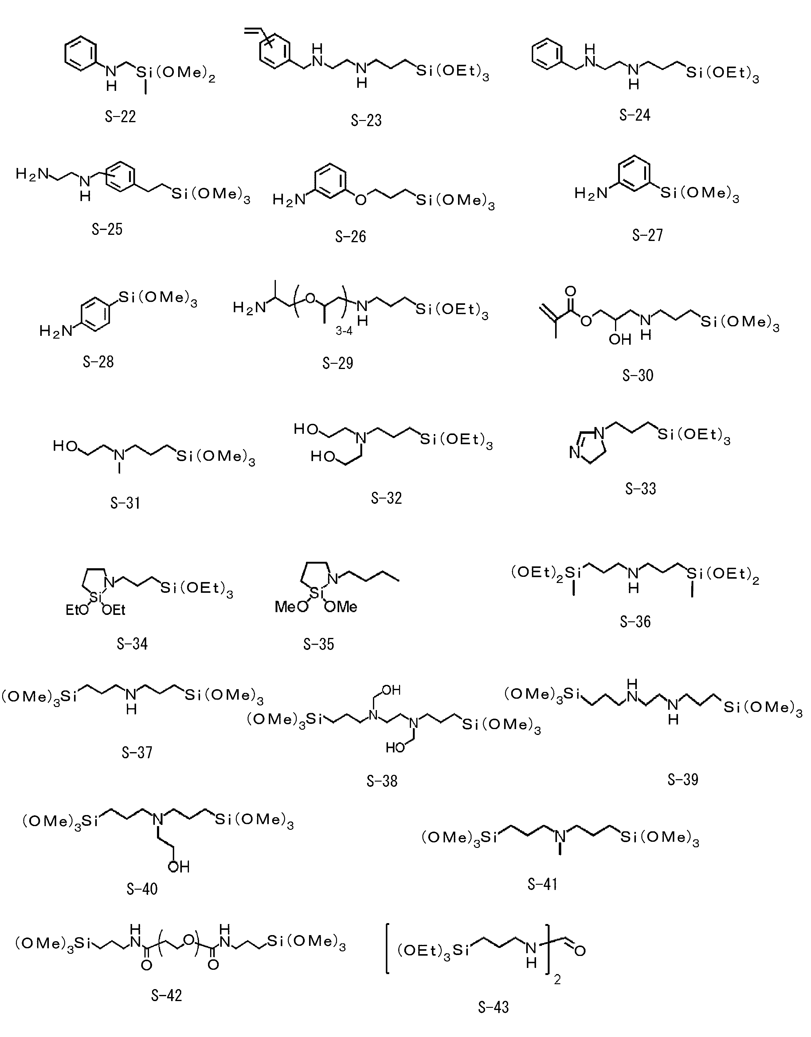
- S-1, S-2, S-3, S-6, S-7, S-12, S-13, S-32, S-33, S-34, and S-37 are And compounds S-1, S-2, S-3, S-6, S-7, S-12, S-13, S-32, S-33, and S-34 described above as specific examples. , And S-37.
- a conventional adhesive layer is formed on the outer periphery of a flexible tube substrate instead of the primer layer and the periphery is coated with a polyurethane elastomer, either adhesion or elasticity is obtained. The result is also inferior (comparative examples 1 and 2).
- the compound of the general formula (1) is used for the primer layer and a polyurethane elastomer is used for the resin coating layer in contact with the primer layer, the obtained flexible tube is in close contact with the substrate and the resin coating layer. It was excellent in gender and also in elasticity (Examples 1 to 12).
Landscapes
- Health & Medical Sciences (AREA)
- Life Sciences & Earth Sciences (AREA)
- Surgery (AREA)
- Chemical & Material Sciences (AREA)
- Engineering & Computer Science (AREA)
- Physics & Mathematics (AREA)
- Optics & Photonics (AREA)
- Medical Informatics (AREA)
- Heart & Thoracic Surgery (AREA)
- Veterinary Medicine (AREA)
- Public Health (AREA)
- General Health & Medical Sciences (AREA)
- Animal Behavior & Ethology (AREA)
- Biophysics (AREA)
- Nuclear Medicine, Radiotherapy & Molecular Imaging (AREA)
- Pathology (AREA)
- Radiology & Medical Imaging (AREA)
- Molecular Biology (AREA)
- Biomedical Technology (AREA)
- Organic Chemistry (AREA)
- Polymers & Plastics (AREA)
- Chemical Kinetics & Catalysis (AREA)
- Medicinal Chemistry (AREA)
- Manufacturing & Machinery (AREA)
- Mechanical Engineering (AREA)
- General Physics & Mathematics (AREA)
- Astronomy & Astrophysics (AREA)
- Endoscopes (AREA)
- Instruments For Viewing The Inside Of Hollow Bodies (AREA)
- Rigid Pipes And Flexible Pipes (AREA)
- Laminated Bodies (AREA)
Abstract
金属製の可撓管基材とその外周を覆う樹脂被覆層とを有し、可撓管基材と樹脂被覆層との間には下記式(1)の化合物を含むプライマー層を有し、樹脂被覆層がプライマー層と接する側にポリウレタンエラストマーを含む内視鏡用可撓管、この内視鏡用可撓管を備えた内視鏡型医療機器、これら内視鏡用可撓管及び内視鏡型医療機器の製造方法。 X1及びX2は水素原子、アルキル基、シクロアルキル基、アルケニル基、アリール基、アシル基、アルコキシカルボニル基又はカルバモイル基を、Y1はヒドロキシ基又はアルコキシ基を、Y2及びY3はヒドロキシ基、アルコキシ基又はアルキル基を示す。 Lは単結合又は特定の2価の基を示す。
Description
本発明は、内視鏡用可撓管、内視鏡型医療機器、及びこれらの製造方法に関する。
内視鏡は、患者の体腔内を観察するための医療用機器である。体腔内に挿入して用いるため、臓器に傷をつけず、患者に痛みないし違和感を与えないものが望まれる。そのような要請から、内視鏡の挿入部(体腔内に挿入される構造部)を構成する可撓管には、柔らかく屈曲する金属帯片を螺旋状に巻いて形成された螺旋管が採用されている。さらに、螺旋管の周囲は柔軟な樹脂で被覆され、この樹脂被覆層が必要によりトップコート層で被覆されて、食道、腸等の体腔内表面に刺激ないし傷を与えない工夫がなされている。
上記の樹脂被覆層は、例えば、螺旋管を筒状網体で覆った可撓管基材の外周面に、樹脂を押し出し成形することにより形成することができる。このとき、先端側は体腔内に挿入しやすくするために軟らかく、後端側は操作しやすくするために硬くすることが好ましい。この点を考慮し、樹脂被覆層として互いに硬さが異なる内層及び外層の二層構造を採用し、内層と外層の厚みの割合を可撓管の軸方向で変化させることが提案されている。
内視鏡の操作性、耐久性等の向上には、可撓管基材とそれを覆う樹脂被覆層との密着性を高めることが重要である。この密着性が十分でないと、可撓管を体腔内に挿入した際に、可撓管の屈曲により樹脂被覆層に皺が生じやすくなり、また、体腔内で可撓管を回転させた際に樹脂被覆層に捩れが生じやすくなる。樹脂被覆層に皺や捩れが生じると、体腔内に可撓管表面が引っ掛かるなどして被検者に苦痛を与えるおそれがある。
このような問題に対処する技術として、特許文献1には、無機物と有機物の両方に対して密着性を示すシランカップリング剤を、可撓管基材と樹脂被覆層との間に配することが記載されている。
また、体腔内において可撓管を滑らかに移動させるために、可撓管には高い弾発性が求められる。可撓管の弾発性を高めることにより、体腔内の屈曲部を通過した可撓管が直線状に戻りやすく、検査時の被検者の負担をより軽減することができる。
このような問題に対処する技術として、特許文献1には、無機物と有機物の両方に対して密着性を示すシランカップリング剤を、可撓管基材と樹脂被覆層との間に配することが記載されている。
また、体腔内において可撓管を滑らかに移動させるために、可撓管には高い弾発性が求められる。可撓管の弾発性を高めることにより、体腔内の屈曲部を通過した可撓管が直線状に戻りやすく、検査時の被検者の負担をより軽減することができる。
本発明は、可撓管基材とそれを覆う樹脂被覆層との密着性に優れ、また弾発性にも優れた内視鏡用可撓管、この内視鏡用可撓管を備えた内視鏡型医療機器を提供することを課題とする。また本発明は、上記内視鏡用可撓管の製造方法及び上記内視鏡型医療機器の製造方法を提供することを課題とする。
本発明者らは内視鏡用可撓管における樹脂被覆層の形成について検討を重ねた結果、金属材料で構成される可撓管基材の表面に、アミノ基を有する特定構造のシランカップリング剤を含むプライマー層を形成し、さらに、このプライマー層に接する樹脂被覆層の構成材料としてポリウレタンエラストマーを採用することにより、得られる可撓管において、可撓管基材と樹脂被覆層との密着性を所望の十分なレベルへと高めることができること、また、この可撓管が弾発性にも優れることを見い出した。本発明は、これらの知見に基づきさらに検討を重ね、完成させるに至ったものである。
本発明の上記課題は下記の手段により解決された。
〔1〕
金属を構成材料とする可撓管基材と、この可撓管基材の外周を覆う樹脂被覆層とを有する内視鏡用可撓管であって、
上記可撓管基材と上記樹脂被覆層との間に下記一般式(1)で表される化合物を含むプライマー層を有し、上記樹脂被覆層が、少なくともプライマー層と接する側にポリウレタンエラストマーを含む、内視鏡用可撓管。

式中、X1及びX2は水素原子、アルキル基、シクロアルキル基、アルケニル基、アリール基、アシル基、アルコキシカルボニル基又はカルバモイル基を示す。
Y1はヒドロキシ基又はアルコキシ基を示す。Y2及びY3はヒドロキシ基、アルコキシ基又はアルキル基を示す。
Lは単結合、又は、アルキレン基、アリーレン基及び-O-から選ばれる2価の基もしくはこの2価の基を2つ以上組合せてなる2価の基を示す。
〔2〕
上記可撓管基材を構成する金属がステンレスである、〔1〕に記載の内視鏡用可撓管。
〔3〕
上記可撓管基材を構成する金属が表面に不動態皮膜を有する、〔1〕又は〔2〕に記載の内視鏡用可撓管。
〔4〕
上記樹脂被覆層が単層構造又は複層構造であり、上記プライマー層と接する層中にポリウレタンエラストマーを含む、〔1〕~〔3〕のいずれか1つに記載の内視鏡用可撓管。
〔5〕
上記樹脂被覆層が2層構造であり、この2層構造の内層及び外層の厚みの割合が、上記可撓管基材の軸方向において傾斜的に変化している、〔1〕~〔4〕のいずれか1つに記載の内視鏡用可撓管。
〔6〕
上記の内層及び外層の厚みの割合が、上記内視鏡用可撓管の一端において内層:外層=5:95~40:60であって、他端において内層:外層=95:5~60:40である、〔1〕~〔5〕のいずれか1つに記載の内視鏡用可撓管。
〔7〕
〔1〕~〔6〕のいずれか1つに記載の内視鏡用可撓管を有する内視鏡型医療機器。
〔8〕
金属を構成材料とする可撓管基材の少なくとも外周に、下記一般式(1)で表される化合物を含むプライマー層を形成する工程、及び
上記可撓管基材の外周に形成された上記プライマー層に接して、ポリウレタンエラストマーを含む樹脂を被覆することにより樹脂被覆層を形成する工程
を含む、内視鏡用可撓管の製造方法。

式中、X1及びX2は水素原子、アルキル基、シクロアルキル基、アルケニル基、アリール基、アシル基、アルコキシカルボニル基又はカルバモイル基を示す。
Y1はヒドロキシ基又はアルコキシ基を示す。Y2及びY3はヒドロキシ基、アルコキシ基又はアルキル基を示す。
Lは単結合、又は、アルキレン基、アリーレン基及び-O-から選ばれる2価の基もしくはこの2価の基を2つ以上組合せてなる2価の基を示す。
〔9〕
上記樹脂被覆層が2層構造であり、この2層構造の少なくとも内層がポリウレタンエラストマーを含み、この2層構造の内層及び外層の厚みの割合が、上記可撓管基材の軸方向において傾斜的に変化している、〔8〕に記載の内視鏡用可撓管の製造方法。
〔10〕
〔8〕又は〔9〕に記載の内視鏡用可撓管の製造方法により内視鏡用可撓管を得る工程、及び、
得られた内視鏡用可撓管を内視鏡用型医療機器の挿入部に組み込む工程
を含む、内視鏡型医療機器の製造方法。
〔11〕
〔1〕~〔6〕のいずれか1つに記載の内視鏡用可撓管を内視鏡用型医療機器の挿入部に組み込むことを含む、内視鏡型医療機器の製造方法。
〔1〕
金属を構成材料とする可撓管基材と、この可撓管基材の外周を覆う樹脂被覆層とを有する内視鏡用可撓管であって、
上記可撓管基材と上記樹脂被覆層との間に下記一般式(1)で表される化合物を含むプライマー層を有し、上記樹脂被覆層が、少なくともプライマー層と接する側にポリウレタンエラストマーを含む、内視鏡用可撓管。
Y1はヒドロキシ基又はアルコキシ基を示す。Y2及びY3はヒドロキシ基、アルコキシ基又はアルキル基を示す。
Lは単結合、又は、アルキレン基、アリーレン基及び-O-から選ばれる2価の基もしくはこの2価の基を2つ以上組合せてなる2価の基を示す。
〔2〕
上記可撓管基材を構成する金属がステンレスである、〔1〕に記載の内視鏡用可撓管。
〔3〕
上記可撓管基材を構成する金属が表面に不動態皮膜を有する、〔1〕又は〔2〕に記載の内視鏡用可撓管。
〔4〕
上記樹脂被覆層が単層構造又は複層構造であり、上記プライマー層と接する層中にポリウレタンエラストマーを含む、〔1〕~〔3〕のいずれか1つに記載の内視鏡用可撓管。
〔5〕
上記樹脂被覆層が2層構造であり、この2層構造の内層及び外層の厚みの割合が、上記可撓管基材の軸方向において傾斜的に変化している、〔1〕~〔4〕のいずれか1つに記載の内視鏡用可撓管。
〔6〕
上記の内層及び外層の厚みの割合が、上記内視鏡用可撓管の一端において内層:外層=5:95~40:60であって、他端において内層:外層=95:5~60:40である、〔1〕~〔5〕のいずれか1つに記載の内視鏡用可撓管。
〔7〕
〔1〕~〔6〕のいずれか1つに記載の内視鏡用可撓管を有する内視鏡型医療機器。
〔8〕
金属を構成材料とする可撓管基材の少なくとも外周に、下記一般式(1)で表される化合物を含むプライマー層を形成する工程、及び
上記可撓管基材の外周に形成された上記プライマー層に接して、ポリウレタンエラストマーを含む樹脂を被覆することにより樹脂被覆層を形成する工程
を含む、内視鏡用可撓管の製造方法。
Y1はヒドロキシ基又はアルコキシ基を示す。Y2及びY3はヒドロキシ基、アルコキシ基又はアルキル基を示す。
Lは単結合、又は、アルキレン基、アリーレン基及び-O-から選ばれる2価の基もしくはこの2価の基を2つ以上組合せてなる2価の基を示す。
〔9〕
上記樹脂被覆層が2層構造であり、この2層構造の少なくとも内層がポリウレタンエラストマーを含み、この2層構造の内層及び外層の厚みの割合が、上記可撓管基材の軸方向において傾斜的に変化している、〔8〕に記載の内視鏡用可撓管の製造方法。
〔10〕
〔8〕又は〔9〕に記載の内視鏡用可撓管の製造方法により内視鏡用可撓管を得る工程、及び、
得られた内視鏡用可撓管を内視鏡用型医療機器の挿入部に組み込む工程
を含む、内視鏡型医療機器の製造方法。
〔11〕
〔1〕~〔6〕のいずれか1つに記載の内視鏡用可撓管を内視鏡用型医療機器の挿入部に組み込むことを含む、内視鏡型医療機器の製造方法。
本明細書において、特定の符号で示された置換基や連結基等(以下、置換基等という)が複数あるとき、あるいは複数の置換基等を同時もしくは択一的に規定するときには、それぞれの置換基等は互いに同一でも異なっていてもよいことを意味する。また、特に断らない場合であっても、複数の置換基等が隣接するときにはそれらが互いに連結したり縮環したりして環を形成していてもよい意味である。
本明細書において置換ないし無置換を明記していない置換基(連結基についても同様)については、所望の効果を奏する範囲で、その基に任意の置換基を有していてもよい意味である。これは置換ないし無置換を明記していない化合物についても同義である。
本明細書において、ある基の炭素数を規定する場合、この炭素数は、基全体の炭素数を意味する。つまり、この基がさらに置換基を有する形態である場合、この置換基を含めた全体の炭素数を意味する。
本明細書において置換ないし無置換を明記していない置換基(連結基についても同様)については、所望の効果を奏する範囲で、その基に任意の置換基を有していてもよい意味である。これは置換ないし無置換を明記していない化合物についても同義である。
本明細書において、ある基の炭素数を規定する場合、この炭素数は、基全体の炭素数を意味する。つまり、この基がさらに置換基を有する形態である場合、この置換基を含めた全体の炭素数を意味する。
本発明の内視鏡用可撓管は、可撓管基材とそれを覆う樹脂被覆層との密着性に優れ、また弾発性にも優れる。
本発明の内視鏡型医療機器は、体腔内に挿入される構造部である可撓管が、可撓管基材とそれを覆う樹脂被覆層との密着性に優れ、また弾発性にも優れる。したがって、本発明の内視鏡型医療機器は使用時における被検者の負担をより軽減することができる。
本発明の内視鏡用可撓管の製造方法によれば、可撓管基材とそれを覆う樹脂被覆層との密着性に優れ、また弾発性にも優れる内視鏡用可撓管を得ることができる。
本発明の内視鏡型医療機器の製造方法によれば、この機器を構成する可撓管を、可撓管基材とそれを覆う樹脂被覆層との密着性に優れたものとすることができ、また、この可撓管の弾発性も高めることができる。したがって、本発明の内視鏡型医療機器の製造方法により、使用時における被検者の負担がより軽減された内視鏡型医療機器を得ることができる。
本発明の内視鏡型医療機器は、体腔内に挿入される構造部である可撓管が、可撓管基材とそれを覆う樹脂被覆層との密着性に優れ、また弾発性にも優れる。したがって、本発明の内視鏡型医療機器は使用時における被検者の負担をより軽減することができる。
本発明の内視鏡用可撓管の製造方法によれば、可撓管基材とそれを覆う樹脂被覆層との密着性に優れ、また弾発性にも優れる内視鏡用可撓管を得ることができる。
本発明の内視鏡型医療機器の製造方法によれば、この機器を構成する可撓管を、可撓管基材とそれを覆う樹脂被覆層との密着性に優れたものとすることができ、また、この可撓管の弾発性も高めることができる。したがって、本発明の内視鏡型医療機器の製造方法により、使用時における被検者の負担がより軽減された内視鏡型医療機器を得ることができる。
本発明の内視鏡型医療機器の好ましい実施形態について、電子内視鏡を例に説明する。電子内視鏡は、内視鏡用可撓管が組み込まれ(以下、内視鏡用可撓管を単に「可撓管」と称することもある)、この可撓管を体腔内に挿入して体腔内を観察等する医療機器として用いられる。図1に示した例において、電子内視鏡2は、体腔内に挿入される挿入部3と、挿入部3の基端部分に連設された本体操作部5と、プロセッサ装置や光源装置に接続されるユニバーサルコード6とを備えている。挿入部3は、本体操作部5に連設される可撓管3aと、そこに連設されるアングル部3bと、その先端に連設され、体腔内撮影用の撮像装置(図示せず)が内蔵された先端部3cとから構成される。挿入部3の大半の長さを占める可撓管3aは、そのほぼ全長にわたって可撓性を有し、特に体腔等の内部に挿入される部位はより可撓性に富む構造となっている。
<可撓管基材>
可撓管は、最内層として金属を構成材料とする可撓管基材を有する。
図2に示すように、可撓管基材14は、最内側に金属帯片11aを螺旋状に巻回することにより形成される螺旋管11に、金属線を編組してなる筒状網体12を被覆して両端に口金13をそれぞれ嵌合した形態とすることが好ましい。可撓管基材14を構成する金属は、腐蝕を防ぐために、その表面に不動態化処理が施されていることが好ましい。すなわち、可撓管基材14はその外周に不動態皮膜を有することが好ましい。この不動態化処理は常法により行うことができる。例えば、硝酸などの強力な酸化剤を含む溶液に浸漬したり、空気(酸素)中もしくは水(水蒸気)中で加熱したり、酸化剤を含む溶液中で陽極酸化したりすることにより、金属表面に不動態皮膜を形成することができる。
可撓管基材14を構成する金属は、ステンレスが好ましい。ステンレス表面は通常、クロムと酸素が結合して不動態皮膜が形成された状態にある。しかし、可撓管基材14の構成材料としてステンレスを使用する場合であっても、ステンレス表面全体に、より均一な不動態皮膜をより確実に形成させるために、ステンレスに上述した不動態化処理を施すことが好ましい。
可撓管は、最内層として金属を構成材料とする可撓管基材を有する。
図2に示すように、可撓管基材14は、最内側に金属帯片11aを螺旋状に巻回することにより形成される螺旋管11に、金属線を編組してなる筒状網体12を被覆して両端に口金13をそれぞれ嵌合した形態とすることが好ましい。可撓管基材14を構成する金属は、腐蝕を防ぐために、その表面に不動態化処理が施されていることが好ましい。すなわち、可撓管基材14はその外周に不動態皮膜を有することが好ましい。この不動態化処理は常法により行うことができる。例えば、硝酸などの強力な酸化剤を含む溶液に浸漬したり、空気(酸素)中もしくは水(水蒸気)中で加熱したり、酸化剤を含む溶液中で陽極酸化したりすることにより、金属表面に不動態皮膜を形成することができる。
可撓管基材14を構成する金属は、ステンレスが好ましい。ステンレス表面は通常、クロムと酸素が結合して不動態皮膜が形成された状態にある。しかし、可撓管基材14の構成材料としてステンレスを使用する場合であっても、ステンレス表面全体に、より均一な不動態皮膜をより確実に形成させるために、ステンレスに上述した不動態化処理を施すことが好ましい。
<プライマー層>
本発明において、可撓管基材の外周には、プライマー層(図示せず)が設けられている。このプライマー層を設けることにより、可撓管基材と、その外周を覆って設けられる後述する樹脂被覆層との密着性を効果的に高めることができる。本発明において、このプライマー層は下記一般式(1)で表される化合物を含む。
本発明において、可撓管基材の外周には、プライマー層(図示せず)が設けられている。このプライマー層を設けることにより、可撓管基材と、その外周を覆って設けられる後述する樹脂被覆層との密着性を効果的に高めることができる。本発明において、このプライマー層は下記一般式(1)で表される化合物を含む。

一般式(1)中、X1及びX2は水素原子、アルキル基、シクロアルキル基、アルケニル基、アリール基、アシル基、アルコキシカルボニル基又はカルバモイル基を示す。
X1及びX2として採り得るアルキル基は、直鎖状でもよく、分岐を有してもよい。このアルキル基の炭素数は1~20の整数が好ましく、1~15がより好ましく、1~10がさらに好ましく、1~8が特に好ましい。
X1及びX2として採り得るアルキル基の具体例として、例えば、メチル、エチル、n-プロピル、イソプロピル、n-ブチル、s-ブチル、イソブチル、t-ブチル、n-ペンチル、n-ヘキシル、n-ヘプチル、及びn-オクチルを挙げることができる。
X1及びX2として採り得るアルキル基の具体例として、例えば、メチル、エチル、n-プロピル、イソプロピル、n-ブチル、s-ブチル、イソブチル、t-ブチル、n-ペンチル、n-ヘキシル、n-ヘプチル、及びn-オクチルを挙げることができる。
X1及びX2として採り得るシクロアルキル基は、炭素数が3~20が好ましく、3~15がより好ましく、3~10がさらに好ましく、3~8が特に好ましい。X1及びX2として採り得るシクロアルキル基の具体例として、例えば、シクロペンチル、及びシクロヘキシルを挙げることができる。
X1及びX2として採り得るアルケニル基は、直鎖状又は分岐状のいずれでもよい。このアルケニル基の炭素数は2~20の整数が好ましく、2~15がより好ましく、2~10がさらに好ましく、2~5が特に好ましい。
X1及びX2として採り得るアリール基の炭素数は6~20の整数が好ましく、6~15がより好ましく、6~12がさらに好ましく、6~10が特に好ましい。
X1及びX2として採り得るアリール基の具体例として、例えば、フェニル及びナフチルを挙げることができ、フェニルが好ましい。
X1及びX2として採り得るアリール基の具体例として、例えば、フェニル及びナフチルを挙げることができ、フェニルが好ましい。
X1及びX2として採り得るアシル基は、炭素数が2~40の整数が好ましく、2~30がより好ましく、2~20がさらに好ましく、2~15が特に好ましい。本発明においてアシル基は、アルキルカルボニル基及びアリールカルボニル基を含む。
X1及びX2として採り得るアルコキシカルボニル基は、炭素数が2~40の整数が好ましく、2~30がより好ましく、2~20がさらに好ましく、2~15が特に好ましい。
X1及びX2として採り得るカルバモイル基は、炭素数が1~40の整数が好ましく、1~30がより好ましく、1~20がさらに好ましく、1~15が特に好ましい。
X1及びX2として採り得るアルキル基、シクロアルキル基、アルケニル基、アリール基、アシル基、アルコキシカルボニル基及びカルバモイル基が置換基を有する場合、この置換基中にはアミノ基(好ましくは窒素原子に結合した水素原子を有するアミノ基であり、より好ましくは無置換のアミノ基)、ヒドロキシ基、及び/又はシリル基(好ましくは置換基を有するシリル基であり、この置換シリル基における置換基全体(シリル基が置換基を3つ有する場合は3つの置換基全体)の炭素数が好ましくは1~10、より好ましくは1~6である。置換基としてアルコキシ基を少なくとも1つ有するシリル基が好ましい。)が含まれることが好ましい(すなわち、上記置換基中には、上記アミノ基、上記ヒドロキシ基、及び上記シリル基の少なくとも1種が含まれることが好ましい。)。
また、X1及びX2として採り得るアルキル基、シクロアルキル基、アルケニル基、アリール基、アシル基、アルコキシカルボニル基及びカルバモイル基が置換基を有する場合、この置換基が、アミノ基(好ましくは窒素原子に結合した水素原子を有するアミノ基であり、より好ましくは無置換のアミノ基)、ヒドロキシ基又はシリル基(好ましくは置換基を有するシリル基であり、この置換シリル基における置換基全体(シリル基が置換基を3つ有する場合は3つの置換基全体)の炭素数が好ましくは1~10、より好ましくは1~6である。置換基としてアルコキシ基を少なくとも1つ有するシリル基が好ましい。)であることも好ましい。
また、X1及びX2として採り得るアルキル基、シクロアルキル基、アルケニル基、アリール基、アシル基、アルコキシカルボニル基及びカルバモイル基が置換基を有する場合、この置換基が、アミノ基(好ましくは窒素原子に結合した水素原子を有するアミノ基であり、より好ましくは無置換のアミノ基)、ヒドロキシ基又はシリル基(好ましくは置換基を有するシリル基であり、この置換シリル基における置換基全体(シリル基が置換基を3つ有する場合は3つの置換基全体)の炭素数が好ましくは1~10、より好ましくは1~6である。置換基としてアルコキシ基を少なくとも1つ有するシリル基が好ましい。)であることも好ましい。
X1とX2は互いに連結して環を形成してもよい。この環の環構成原子数は3~10が好ましく、4~8がより好ましく、5又は6が好ましい。また、X1とX2が互いに連結して形成し得る環は、通常、環構成原子として窒素原子の他に炭素原子を含み、また窒素原子以外のヘテロ原子を有してもよい。窒素原子以外のヘテロ原子としては、例えば酸素原子、硫黄原子、及びケイ素原子を挙げることができる。
X1及びX2はいずれも水素原子であることが好ましい。また、X1及びX2のうち一方が水素原子で、他方が、アミノ基を有するアルキル基であることも好ましい。
Y1はヒドロキシ基又はアルコキシ基を示し、アルコキシ基が好ましい。
Y1として採り得るアルコキシ基を構成するアルキル基としては、上記のX1及びX2として採り得るアルキル基を挙げることができ、好ましい形態もX1及びX2として採り得るアルキル基の好ましい形態と同じである。
Y1として採り得るアルコキシ基を構成するアルキル基としては、上記のX1及びX2として採り得るアルキル基を挙げることができ、好ましい形態もX1及びX2として採り得るアルキル基の好ましい形態と同じである。
Y2及びY3はヒドロキシ基、アルコキシ基又はアルキル基を示す。Y2及びY3として採り得るアルコキシ基はY1として採り得るアルコキシ基と同義であり、好ましい形態も同じである。また、Y2及びY3として採り得るアルキル基としては、上記のX1及びX2として採り得るアルキル基と同義であり、好ましい形態も同じである。
Y1、Y2及びY3のうち、少なくとも1つがアルコキシ基であることが好ましく、少なくとも2つがアルコキシ基であることがより好ましく、Y1、Y2及びY3のすべてがアルコキシ基であることがさらに好ましい。
一般式(1)において、X2とY3は、互いに連結して環を形成していてもよい。この環の環構成原子数は3~10が好ましく、4~8がより好ましく、5又は6が好ましい。X2とY3が互いに連結して環を形成する場合、後述するLは単結合が好ましい。また、X2とY3が互いに連結して形成し得る環において、窒素原子とケイ素原子以外の環構成原子は炭素原子であることが好ましい。
Lは単結合であるか、又は、アルキレン基、アリーレン基及び-O-(エーテル結合)から選ばれる2価の基であるか、又は、アルキレン基、アリーレン基及び-O-から選ばれる2価の基を組合せてなる2価の基である。Lが2価の基の場合、Lの分子量は14~300が好ましく、14~210がより好ましい。
Lを構成し得るアルキレン基は、直鎖でもよく、分岐を有してもよい。このアルキレン基の炭素数は1~20の整数が好ましく、1~15がより好ましく、1~12がさらに好ましく、1~8がさらに好ましい。
Lを構成し得るアリーレン基は、炭素数は6~20の整数が好ましく、6~15がより好ましく、6~12がさらに好ましく、6~10が特に好ましい。Lを構成し得るアリーレン基は特に好ましくはフェニレンである。
Lはアルキレン基が好ましく、直鎖アルキレン基がより好ましい。この直鎖アルキレン基の炭素数は1~12の整数であることが好ましく、より好ましくは1~6である。
プライマー層を構成する上記一般式(1)の化合物は、シランカップリング剤として機能する。すなわち、一般式(1)中の「-Si(Y1)(Y2)Y3」が可撓管基材を構成する金属と相互作用し、「-N(X1)X2」が、樹脂被覆層を構成するポリウレタンエラストマーと相互作用することにより、可撓管基材の外周を覆う樹脂被覆層を可撓管基材表面に強固に密着させることができると考えられる。
「-Si(Y1)(Y2)Y3」の可撓管基材14を構成する金属との相互作用としては、例えば、この基のSi原子が有するアルコキシ基が加水分解して生じるヒドロキシ基、あるいはSi原子が有するヒドロキシ基と、可撓管基材金属表面のヒドロキシ基等との間の縮重合反応を挙げることができる。
また、「-N(X1)X2」とポリウレタンエラストマーとの相互作用は必ずしも明らかではないが、-N(X1)X2とウレタン結合との間の水素結合、及びポリウレタンエラストマー中のイソシアネート残基との共有結合等が効率的に生じ、樹脂被覆層との密着性の向上に寄与するものと考えられる。
可撓管基材と樹脂被覆層との密着性向上のために、これまで、可撓管基材と樹脂被覆層との間に接着剤層を設けることが広く行われてきた。この接着剤層の一例として、ポリウレタン等のポリマーと、ポリイソシアネート化合物とからなる組成物で形成されたものが知られている。この接着剤層は一定の厚みを有する柔らかい層である。
これに対し、本発明で用いる一般式(1)の化合物は、単分子で、可撓管基材と樹脂被覆層との接着に寄与するものであり、プライマー層の層厚は通常の接着剤層よりも格段に薄い(換言すれば、厚みという概念を想起できない。)。すなわち、一般式(1)の化合物を含むプライマー層は、可撓管基材と樹脂被覆層との接着のために一定の層厚と柔らかさを必要とする接着剤層とは異なる。それゆえプライマー層は可撓管の弾発性には事実上影響せず、本発明の可撓管は弾発性にも優れるものとなる。
「-Si(Y1)(Y2)Y3」の可撓管基材14を構成する金属との相互作用としては、例えば、この基のSi原子が有するアルコキシ基が加水分解して生じるヒドロキシ基、あるいはSi原子が有するヒドロキシ基と、可撓管基材金属表面のヒドロキシ基等との間の縮重合反応を挙げることができる。
また、「-N(X1)X2」とポリウレタンエラストマーとの相互作用は必ずしも明らかではないが、-N(X1)X2とウレタン結合との間の水素結合、及びポリウレタンエラストマー中のイソシアネート残基との共有結合等が効率的に生じ、樹脂被覆層との密着性の向上に寄与するものと考えられる。
可撓管基材と樹脂被覆層との密着性向上のために、これまで、可撓管基材と樹脂被覆層との間に接着剤層を設けることが広く行われてきた。この接着剤層の一例として、ポリウレタン等のポリマーと、ポリイソシアネート化合物とからなる組成物で形成されたものが知られている。この接着剤層は一定の厚みを有する柔らかい層である。
これに対し、本発明で用いる一般式(1)の化合物は、単分子で、可撓管基材と樹脂被覆層との接着に寄与するものであり、プライマー層の層厚は通常の接着剤層よりも格段に薄い(換言すれば、厚みという概念を想起できない。)。すなわち、一般式(1)の化合物を含むプライマー層は、可撓管基材と樹脂被覆層との接着のために一定の層厚と柔らかさを必要とする接着剤層とは異なる。それゆえプライマー層は可撓管の弾発性には事実上影響せず、本発明の可撓管は弾発性にも優れるものとなる。
一般式(1)で表される化合物の具体例を以下に示すが、本発明はこれらに限定されるものではない。下記構造中、Meはメチル、Etはエチルを示す。

<樹脂被覆層>
本発明の可撓管は、プライマー層が設けられた可撓管基材の外周に樹脂被覆層を有する。
図2の形態では、樹脂被覆層15の外面に、耐薬品性等に寄与する、フッ素等を含有したトップコート層16をコーティングしている。図2において、螺旋管11は1層だけ図示されているが、同軸に2層以上重ねて構成してもよい。なお、図面において、樹脂被覆層15及びトップコート層16は、層構造を明確に図示するため、可撓管基材14の径に比して厚く描いている。
本発明の可撓管は、プライマー層が設けられた可撓管基材の外周に樹脂被覆層を有する。
図2の形態では、樹脂被覆層15の外面に、耐薬品性等に寄与する、フッ素等を含有したトップコート層16をコーティングしている。図2において、螺旋管11は1層だけ図示されているが、同軸に2層以上重ねて構成してもよい。なお、図面において、樹脂被覆層15及びトップコート層16は、層構造を明確に図示するため、可撓管基材14の径に比して厚く描いている。
本発明において樹脂被覆層は、上述したプライマー層を有する可撓管基材の外周面を被覆する。図2の形態では、樹脂被覆層15は、可撓管基材14の軸回りの全周面を被覆する内層17と、内層17の軸回りの全周面を被覆する外層18とを積層した二層構成である。通常、内層17の材料には、軟質樹脂が使用され、外層18の材料には、硬質樹脂が使用されるが、本発明はこれらの形態に限定されるものではない。
本発明においては後述するように、樹脂被覆層が2層以上の複層構造の場合には、少なくとも最内層(プライマー層と接する層)にポリウレタンエラストマーが含まれる。また、本発明において樹脂被覆層が単層の場合には、この単層の樹脂被覆層にはポリウレタンエラストマーが含まれる。すなわち、本発明において樹脂被覆層は、少なくともプライマー層と接する側にポリウレタンエラストマーを含む。
本発明においては後述するように、樹脂被覆層が2層以上の複層構造の場合には、少なくとも最内層(プライマー層と接する層)にポリウレタンエラストマーが含まれる。また、本発明において樹脂被覆層が単層の場合には、この単層の樹脂被覆層にはポリウレタンエラストマーが含まれる。すなわち、本発明において樹脂被覆層は、少なくともプライマー層と接する側にポリウレタンエラストマーを含む。
(ポリウレタンエラストマー)
樹脂被覆層に用いるポリウレタンエラストマーとしては、可撓管の形成に適用可能な通常のポリウレタンエラストマーを採用することができる。このポリウレタンエラストマーは通常、ポリイソシアネート、ポリオール及び鎖伸長剤を反応させることにより得られるものである。このポリウレタンエラストマーは、ポリオールとポリイソシアネートの反応によってできたソフトセグメントと鎖伸長剤とポリイソシアネートの反応によってできたハードセグメントとからなるブロックコポリマーであることが好ましい。
樹脂被覆層に用いるポリウレタンエラストマーとしては、可撓管の形成に適用可能な通常のポリウレタンエラストマーを採用することができる。このポリウレタンエラストマーは通常、ポリイソシアネート、ポリオール及び鎖伸長剤を反応させることにより得られるものである。このポリウレタンエラストマーは、ポリオールとポリイソシアネートの反応によってできたソフトセグメントと鎖伸長剤とポリイソシアネートの反応によってできたハードセグメントとからなるブロックコポリマーであることが好ましい。
上記ポリイソシアネートとしては、例えばジフェニルメタンジイソシアネート、ヘキサメチレンジイソシアネート、トリジンジイソシアネート、1,5-ナフタレンジイソシアネート、イソホロンジイソシアネート、キシリレンジイソシアネート等が挙げられる。これらのうち、ジフェニルメタンジイソシアネート及びヘキサメチレンジイソシアネートの少なくとも1種が、耐擦過傷性の点で好ましく、イソホロンジイソシアネートであった場合は消毒薬耐性の点で好ましい。
上記ポリオールとしては、例えばポリテトラメチレンエーテルグリコール、ポリエステルポリオール、ラクトン系ポリエステルポリオール等が挙げられる。ポリエステルポリオールは、ジカルボン酸とジオールの重縮合反応により得られる。ポリエステルポリオールの製造に用いられるジオールは具体的には、エタンジオール、1,3-プロパンジオール、1,4-ブタンジオール、1,5-ペンタンジオール、1,6-ヘキサンジオール等が挙げられ、これらの単独、あるいは併用したものである。また、ジカルボン酸はアジピン酸、セバシン酸等が挙げられ、これらの単独、あるいは併用したものが挙げられる。
これらのポリオールのうち、高い反発弾性が得られるという点からは、ポリテトラメチレンエーテルグリコールが好ましい。
これらのポリオールのうち、高い反発弾性が得られるという点からは、ポリテトラメチレンエーテルグリコールが好ましい。
上記の鎖伸長剤としては、例えばエタンジオール、1,4-ブタンジオール、1,6-ヘキサンジオール等の炭素原子数が2~6の脂肪族直鎖ジオール、1,4-ビス(ヒドロキシエトキシ)ベンゼン等が挙げられる。ヘキサメチレンジアミン、イソホロンジアミン、トリレンジアミン、モノエタノールアミン等のようなアミン類も必要により併用して用いることができる。これらのうち、耐擦過傷性の点からは、炭素原子数が2~6の脂肪族直鎖ジオールが好ましい。
上記の実施形態に係るポリウレタンエラストマーとしては、例えば、特開2005-015643号公報の開示を参照することができる。本発明に用いるポリウレタンエラストマーは、弾発性をより高める観点からはポリエステル構造を有することが好ましい。
上記ポリウレタンエラストマーは、1種単独で用いてもよく、2種以上を組合せて用いてもよい。
上記の実施形態に係るポリウレタンエラストマーとしては、例えば、特開2005-015643号公報の開示を参照することができる。本発明に用いるポリウレタンエラストマーは、弾発性をより高める観点からはポリエステル構造を有することが好ましい。
上記ポリウレタンエラストマーは、1種単独で用いてもよく、2種以上を組合せて用いてもよい。
樹脂被覆層が単層の場合の樹脂被覆層中のポリウレタンエラストマーの含有量、及び、樹脂被覆層が複層の場合における最内層中のポリウレタンエラストマーの含有量は、50質量%以上であることが好ましく、より好ましくは70質量%以上、さらに好ましくは80質量%以上、さらに好ましくは90質量%以上である。また、樹脂被覆層が単層の場合の樹脂被覆層はポリウレタンエラストマーからなる層であってもよく、また、樹脂被覆層が複層の場合における最内層は、ポリウレタンエラストマーからなる層であってもよい。
樹脂被覆層が単層の場合の樹脂被覆層、及び、樹脂被覆層が複層の場合における最内層が、ポリウレタンエラストマー以外の樹脂を含む場合、この樹脂は本発明の効果を損なわない限り特に制限はない。例えば、ポリエステルエラストマー及びポリアミドエラストマーを挙げることができる。
樹脂被覆層が単層の場合の樹脂被覆層、及び、樹脂被覆層が複層の場合における最内層が、ポリウレタンエラストマー以外の樹脂を含む場合、この樹脂は本発明の効果を損なわない限り特に制限はない。例えば、ポリエステルエラストマー及びポリアミドエラストマーを挙げることができる。
本発明において、ポリエステルエラストマーとしては、可撓管の形成に適用可能な通常のポリエステルエラストマーを用いることができる。
すなわち、本発明に用いられるポリエステルエラストマーは、結晶性ポリエステルからなるハードセグメントと、ポリエーテル又はポリエステルからなるソフトセグメントとにより構成された共重合体である。
ハードセグメントとしては、ポリブチレンテレフタレート、ポリエチレンテレフタレート、等が挙げられる。
ソフトセグメントとしては、ポリテトラメチレングリコール、ポリプロピレングリコールのようなポリアルキレングリコール、ビスフェノールAエチレンオキサイド付加物、ビスフェノールAプロピレンオキサイド付加物、ポリカプロラクトンのようなポリエステル等が挙げられる。
本発明において「ポリエステルエラストマー」は、分子中にウレタン結合を含まず、かつアミド結合を含まないことが好ましい。ポリエステルエラストマーは1種を単独で用いてもよく、2種以上を組み合わせて用いてもよい。
すなわち、本発明に用いられるポリエステルエラストマーは、結晶性ポリエステルからなるハードセグメントと、ポリエーテル又はポリエステルからなるソフトセグメントとにより構成された共重合体である。
ハードセグメントとしては、ポリブチレンテレフタレート、ポリエチレンテレフタレート、等が挙げられる。
ソフトセグメントとしては、ポリテトラメチレングリコール、ポリプロピレングリコールのようなポリアルキレングリコール、ビスフェノールAエチレンオキサイド付加物、ビスフェノールAプロピレンオキサイド付加物、ポリカプロラクトンのようなポリエステル等が挙げられる。
本発明において「ポリエステルエラストマー」は、分子中にウレタン結合を含まず、かつアミド結合を含まないことが好ましい。ポリエステルエラストマーは1種を単独で用いてもよく、2種以上を組み合わせて用いてもよい。
上記ポリアミドエラストマーもまた、可撓管の形成に適用可能な通常のポリアミドエラストマーを用いることができる。なお、本発明において上記ポリアミドエラストマーはウレタン結合を有しないことが好ましい。ポリアミドエラストマーは1種を単独で用いてもよく、2種以上を組み合わせて用いてもよい。
樹脂被覆層が複層の場合における最内層以外の層は、ポリウレタンエラストマー、ポリアミドエラストマー及びポリエステルエラストマーの少なくとも1種を含むことが好ましい。これらの樹脂を適宜に組み合わせて所望の物性を有する層を形成することができる。樹脂被覆層が複層の場合における最内層以外の層は、弾発性をより高める観点から、より好ましくはポリウレタンエラストマーを含み、又はポリウレタンエラストマーとポリエステルエラストマーとのアロイを含む。
本発明の樹脂被覆層に用い得る上記各エラストマーは、分子量1万~100万が好ましく、分子量2万~50万がより好ましく、分子量3万~30万が特に好ましい。
本発明において、エラストマーの分子量は、特に断らない限り、重量平均分子量を意味する。重量平均分子量は、GPCによってポリスチレン換算の分子量として計測することができる。このとき、GPC装置HLC-8220(商品名、東ソー社製)を用い、溶離液としては、ポリエステルエラストマーの場合はクロロホルム、ポリウレタンエラストマーの場合はNMP(N-メチル-2-ピロリドン)、ポリアミドエラストマーの場合はm-クレゾール/クロロホルム(湘南和光純薬社製)を用いカラムはG3000HXL+G2000HXL(いずれも商品名、東ソー社製)を用い、23℃で流量は1mL/minで、RIで検出することとする。
本発明において、エラストマーの分子量は、特に断らない限り、重量平均分子量を意味する。重量平均分子量は、GPCによってポリスチレン換算の分子量として計測することができる。このとき、GPC装置HLC-8220(商品名、東ソー社製)を用い、溶離液としては、ポリエステルエラストマーの場合はクロロホルム、ポリウレタンエラストマーの場合はNMP(N-メチル-2-ピロリドン)、ポリアミドエラストマーの場合はm-クレゾール/クロロホルム(湘南和光純薬社製)を用いカラムはG3000HXL+G2000HXL(いずれも商品名、東ソー社製)を用い、23℃で流量は1mL/minで、RIで検出することとする。
図2に示すように、本発明において樹脂被覆層15は、可撓管基材14の長手方向(軸方向)においてほぼ均一な厚みで形成されることが好ましい。樹脂被覆層15の厚みは、例えば、0.2mm~1.0mmであり、可撓管3aの外径Dは、例えば、11~14mmである。図2において内層17及び外層18の厚みは、可撓管基材14の軸方向において、樹脂被覆層15の全体の厚みに対して、各層17、18の厚みの割合が変化するように形成されている。具体的には、アングル部3bに取り付けられる可撓管基材14の一端14a側(先端側)は、樹脂被覆層15の全厚みに対して、内層17の厚みの方が外層18の厚みよりも大きい。そして、一端14aから本体操作部5に取り付けられる他端14b側(基端側)に向かって、徐々に内層17の厚みが漸減し、他端14b側では、外層18の厚みの方が内層17の厚みよりも大きくなっている。
図2において、一端14aにおける内層17の厚みの割合が最大であり、他端14bにおいて、外層18の厚み割合が最大である。内層17の厚み:外層18の厚みは、一端14aにおいて、例えば9:1とし、他端14bにおいて、例えば1:9とすることができる。両端14aから14bにかけて、内層17と外層18の厚みの割合が逆転するように、両層の厚みを変化させている。これにより、可撓管3aは、一端14a側と、他端14b側の硬度に差が生じ、一端14a側が軟らかく、他端14b側が硬くなるように軸方向において柔軟性を変化させることができる。上記内層及び外層は、一端における厚みの割合を5:95~40:60(内層:外層)とすることが好ましく、他端における厚みの割合を95:5~60:40(内層:外層)とすることが好ましい。
なお、内層17と外層18との厚みの割合を5:95~95:5の範囲内とすることにより、薄い方の樹脂の押し出し量についても、精密に制御することが可能である。
なお、内層17と外層18との厚みの割合を5:95~95:5の範囲内とすることにより、薄い方の樹脂の押し出し量についても、精密に制御することが可能である。
内層17及び外層18に用いる軟質樹脂及び硬質樹脂は、成形後の硬度を表す指標である100%モジュラス値の差が1MPa以上であることが好ましく、3MPa以上であることがより好ましい。溶融状態の樹脂の流動性を表す指標である150℃~300℃の成形温度における溶融粘度の差は、2500Pa・s以下であることが好ましい。これにより、内層17及び外層18からなる樹脂被覆層15は、良好な成形精度と、先端側と基端側において必要な硬度差の両方が確保される。
[トップコート層]
本発明の可撓管には、樹脂被覆層15の外周には、必要によりトップコート層16が配される。トップコート層の材料は特に制限されないが、ウレタン塗料、アクリル塗料、フッ素塗料、シリコーン塗料、エポキシ塗料、ポリエステル塗料などが適用される。
トップコート層を使用する主な目的は、可撓管表面の保護や艶出し、滑り性の付与、そして耐薬品性の付与である。そのため、トップコート層としては弾性率が高く、かつ表面が平滑になり、耐薬品性に優れるものが好ましい。
本発明の可撓管には、樹脂被覆層15の外周には、必要によりトップコート層16が配される。トップコート層の材料は特に制限されないが、ウレタン塗料、アクリル塗料、フッ素塗料、シリコーン塗料、エポキシ塗料、ポリエステル塗料などが適用される。
トップコート層を使用する主な目的は、可撓管表面の保護や艶出し、滑り性の付与、そして耐薬品性の付与である。そのため、トップコート層としては弾性率が高く、かつ表面が平滑になり、耐薬品性に優れるものが好ましい。
<可撓管の製造方法>
(プライマー層の形成)
本発明の可撓管基材の製造において、可撓管基材にはまず、プライマー層が形成される。プライマー層は、上記一般式(1)で表される化合物を溶媒に溶解して塗布液を調製し、この塗布液を可撓管基材の外周に塗布したり、スプレーしたり、あるいはこの塗布液中に可撓管基材を浸漬したりするなどして可撓管基材の少なくとも外周に塗布膜を形成した後、塗布膜を常法により乾燥(例えば100℃程度の高温乾燥等)することによって形成することができる。
塗布液に用いる溶媒としては、メタノール、エタノールなどのアルコール系溶媒、アセトン、メチルエチルケトンなどのケトン系溶媒、酢酸エチルなどのエステル系溶媒、トルエンなどの炭化水素系溶媒又はこれらの混合液を用いることができ、さらにこれらの溶剤に対してシランカップリング剤の加水分解を促進させるために水を混合することが好ましい。また、塗布液は酸性(例えば25℃におけるpH1~4)又はアルカリ性(例えば25℃におけるpH9~11)に調製してもよい。
塗布液中の一般式(1)で表される化合物の含有量は特に制限されず、例えば、0.01~2質量%とすることができ、0.02質量%以上0.5質量%未満が好ましく、0.03質量%以上0.4質量%未満とすることがより好ましい。
塗布液中には、一般式(1)で表される化合物、溶媒、pH調整剤の他にも、界面活性剤、触媒等を含んでもよい。塗布液はより好ましくは、一般式(1)で表される化合物と溶媒とで構成される。
本発明においては、本発明の効果を損なわない範囲で、可撓管基材の外周の一部に、プライマー層で覆われていない部分があってもよい(すなわち、プライマー層の一部に欠陥が生じていてもよい。)。
(プライマー層の形成)
本発明の可撓管基材の製造において、可撓管基材にはまず、プライマー層が形成される。プライマー層は、上記一般式(1)で表される化合物を溶媒に溶解して塗布液を調製し、この塗布液を可撓管基材の外周に塗布したり、スプレーしたり、あるいはこの塗布液中に可撓管基材を浸漬したりするなどして可撓管基材の少なくとも外周に塗布膜を形成した後、塗布膜を常法により乾燥(例えば100℃程度の高温乾燥等)することによって形成することができる。
塗布液に用いる溶媒としては、メタノール、エタノールなどのアルコール系溶媒、アセトン、メチルエチルケトンなどのケトン系溶媒、酢酸エチルなどのエステル系溶媒、トルエンなどの炭化水素系溶媒又はこれらの混合液を用いることができ、さらにこれらの溶剤に対してシランカップリング剤の加水分解を促進させるために水を混合することが好ましい。また、塗布液は酸性(例えば25℃におけるpH1~4)又はアルカリ性(例えば25℃におけるpH9~11)に調製してもよい。
塗布液中の一般式(1)で表される化合物の含有量は特に制限されず、例えば、0.01~2質量%とすることができ、0.02質量%以上0.5質量%未満が好ましく、0.03質量%以上0.4質量%未満とすることがより好ましい。
塗布液中には、一般式(1)で表される化合物、溶媒、pH調整剤の他にも、界面活性剤、触媒等を含んでもよい。塗布液はより好ましくは、一般式(1)で表される化合物と溶媒とで構成される。
本発明においては、本発明の効果を損なわない範囲で、可撓管基材の外周の一部に、プライマー層で覆われていない部分があってもよい(すなわち、プライマー層の一部に欠陥が生じていてもよい。)。
プライマー層の形成の前に、可撓管基材はアルカリ溶液、界面活性剤水溶液、有機溶剤等により脱脂洗浄しておくことが好ましい。また、上記洗浄後、さらに水ないし温水を用いて洗浄しておくことが好ましい。
(樹脂被覆層の形成)
樹脂被覆層の形成について、樹脂被覆層が2層構造の場合を例にして説明する。
樹脂被覆層が内層と外層からなる2層構造の可撓管は、例えば、上記内層を構成する第1樹脂材料(ポリウレタンエラストマーを含む樹脂材料)と、上記外層を構成する第2樹脂材料とを、上記のプライマー層を形成した可撓管基材の周囲に溶融混練して押し出し成形し、上記可撓管基材を被覆することにより得ることができる。
なお、樹脂被覆層が1層あるいは3層以上の態様も、下記方法を参照し、適宜に層構成を変えることによる得ることができる。
樹脂被覆層の形成について、樹脂被覆層が2層構造の場合を例にして説明する。
樹脂被覆層が内層と外層からなる2層構造の可撓管は、例えば、上記内層を構成する第1樹脂材料(ポリウレタンエラストマーを含む樹脂材料)と、上記外層を構成する第2樹脂材料とを、上記のプライマー層を形成した可撓管基材の周囲に溶融混練して押し出し成形し、上記可撓管基材を被覆することにより得ることができる。
なお、樹脂被覆層が1層あるいは3層以上の態様も、下記方法を参照し、適宜に層構成を変えることによる得ることができる。
図3、図4に基づき可撓管3a(図1、図2)の樹脂被覆層の形成方法の一例について説明する。この形態では、樹脂被覆層15を成形するために連続成形機を用いる。連続成形機20は、ホッパ、スクリュー21a及び22aなどからなる周知の押し出し部21及び22と、可撓管基材14の外周面に樹脂被覆層15を被覆成形するためのヘッド部23と、冷却部24と、連結可撓管基材31をヘッド部23へ搬送する搬送部25(供給ドラム28と、巻取ドラム29)と、これらを制御する制御部26とからなるものを用いることが好ましい。ヘッド部23は、ニップル32、ダイス33、及びこれらを固定的に支持する支持体34からなるものが好ましい。このような装置の構成例としては、例えば、特開2011-72391号公報の図3~5に記載の装置を使用することができる。
ダイス33の内部を所定の成形温度に加熱することが好ましい。成形温度は、150℃~300℃の範囲に設定されることが好ましい。装置内の加熱部を加熱温調することにより第1樹脂材料39及び第2樹脂材料40の各温度を高温にすることができるが、これに加え、スクリュー21a及び22aの各回転数が高いほど、第1樹脂材料39及び第2樹脂材料40の各温度をさらに高くすることができ、それぞれの流動性を高めることができる。このとき、連結可撓管基材31の搬送速度を一定とし、溶融状態の第1樹脂材料39及び第2樹脂材料40の各吐出量を変更することにより、内層17及び外層18の各成形厚みを調整することができる。
連続成形機20で連結可撓管基材31に樹脂被覆層15を成形するときのプロセスについて説明すると、連続成形機20が成形工程を行うときは、押し出し部21及び22から溶融状態の第1樹脂材料39及び第2樹脂材料40がヘッド部23へと押し出される。これとともに、搬送部25が動作して連結可撓管基材31がヘッド部23へと搬送される。このとき、押し出し部21及び22は、第1樹脂材料39及び第2樹脂材料40を常時押し出してヘッド部23へ供給する状態であり、押し出し部21及び22からゲート35及び36へ押し出された第1樹脂材料39及び第2樹脂材料40は、エッジを通過して合流し、重なった状態で樹脂通路38を通って成形通路37へ供給される。これにより、第1樹脂材料39を使用した内層17と第2樹脂材料40を使用した外層18が重なった二層成形の樹脂被覆層15が形成される。
連結可撓管基材31は、複数の可撓管基材14(この可撓管基材14の外周にはプライマー層が形成されている)が連結されたものであり、成形通路37内を搬送中に、複数の可撓管基材14に対して連続的に樹脂被覆層15が成形される。1つの可撓管基材の一端14a側(先端側)から他端14b側(基端側)まで樹脂被覆層15を成形するとき、押し出し部21及び22による樹脂の吐出を開始した直後は、内層17の厚みを厚くとる。そして、他端14b側へ向かう中間部分で徐々に外層18の厚みの割合を漸増させる。これにより、上記の傾斜的な樹脂被覆層15の厚み割合となるように樹脂の吐出量を制御することが好ましい。
ジョイント部材30は、2つの可撓管基材14の連結部であるので、制御部26は押し出し部21及び22の吐出量の切り替えに利用される。具体的には、制御部26は、1本の可撓管基材14の他端14b側(基端側)における厚みの割合から、次の可撓管基材14の一端14a側(先端側)の厚みの割合になるように、押し出し部21及び22の吐出量を切り替えることが好ましい。次の可撓管基材14の一端14a側から他端14b側まで樹脂被覆層15を成形するときは、同様に一端側から他端側へ向かって徐々に外層の厚みが大きくなるように、押し出し部21及び22が制御されることが好ましい。
最後端まで樹脂被覆層15が成形された連結可撓管基材31は、連続成形機20から取り外された後、可撓管基材14からジョイント部材30が取り外され、各可撓管基材14に分離される。次に、分離された可撓管基材14に対して、樹脂被覆層15の上にトップコート層16がコーティングされて、可撓管3aが完成する。完成した可撓管3aは、電子内視鏡の組立工程へ搬送される。
本発明において、樹脂被覆層は複層である場合、複層を構成する各層の間には、機能層が介在していてもよい。
上記の説明は、図面を参照して、撮像装置を用いて被検体の状態を撮像した画像を観察する電子内視鏡を例に上げて説明しているが、本発明はこれに限るものではなく、光学的イメージガイドを採用して被検体の状態を観察する内視鏡にも適用することができる。
上記の説明は、図面を参照して、撮像装置を用いて被検体の状態を撮像した画像を観察する電子内視鏡を例に上げて説明しているが、本発明はこれに限るものではなく、光学的イメージガイドを採用して被検体の状態を観察する内視鏡にも適用することができる。
本発明の可撓管は、内視鏡型医療機器に対して広く適用することができる。例えば、内視鏡の先端にクリップやワイヤーを装備したもの、あるいはバスケットやブラシを装備した器具に適用することもできる。なお、内視鏡型医療機器とは、上述した内視鏡を基本構造とする医療機器のほか、遠隔操作型の医療機器など、挿入部が可撓性を有し、体内に導入して用いられる医療ないし診療機器を広く含む意味である。
本発明の内視鏡型医療機器は、その挿入部に本発明の内視鏡用可撓管が組み込まれている。すなわち、本発明の内視鏡型医療機器の製造方法は、本発明の内視鏡用可撓管を、内視鏡型医療機器の挿入部に組み込むことを含むものである。
本発明の内視鏡型医療機器は、その挿入部に本発明の内視鏡用可撓管が組み込まれている。すなわち、本発明の内視鏡型医療機器の製造方法は、本発明の内視鏡用可撓管を、内視鏡型医療機器の挿入部に組み込むことを含むものである。
以下に、本発明について実施例を通じてさらに詳細に説明するが、本発明がこれらにより限定して解釈されるものではない。
[プライマー層形成用塗布液の調製]
水/エタノールの質量比を5/75とした溶液を調製した。この溶液に、下表に示す化合物を8.9g/kgの濃度となるように溶解し、プライマー層形成用塗布液とした。
水/エタノールの質量比を5/75とした溶液を調製した。この溶液に、下表に示す化合物を8.9g/kgの濃度となるように溶解し、プライマー層形成用塗布液とした。
[接着剤層形成用塗布液の調製]
ポリエステルポリウレタン(商品名:N-2304、日本ポリウレタン社製)100g及びポリイソシアネート(商品名:コロネート、日本ポリウレタン社製)10gを、メチルエチルケトン1kgに溶解し、接着剤層形成用塗布液とした。
ポリエステルポリウレタン(商品名:N-2304、日本ポリウレタン社製)100g及びポリイソシアネート(商品名:コロネート、日本ポリウレタン社製)10gを、メチルエチルケトン1kgに溶解し、接着剤層形成用塗布液とした。
[内視鏡用可撓管の作製]
図2に示す構造の可撓管を作製した。なお樹脂被覆層は、下表の通り、単層構造又は2層構造とした。
図2に示す構造の可撓管を作製した。なお樹脂被覆層は、下表の通り、単層構造又は2層構造とした。
<可撓管基材>
ステンレス製の金属帯片11aを用いて螺旋管11を形成し、この螺旋管11を、ステンレス製の繊維を織り込んだ筒状網体12で被覆した形態の可撓管基材を用意した。この可撓管基材は、長さ80cm、直径12mmである。このステンレス製可撓管は、螺旋管及び筒状網体の形成時におけるアニール処理(加熱処理)により、表面に不動態層が形成されている。
ステンレス製の金属帯片11aを用いて螺旋管11を形成し、この螺旋管11を、ステンレス製の繊維を織り込んだ筒状網体12で被覆した形態の可撓管基材を用意した。この可撓管基材は、長さ80cm、直径12mmである。このステンレス製可撓管は、螺旋管及び筒状網体の形成時におけるアニール処理(加熱処理)により、表面に不動態層が形成されている。
<プライマー層の形成>
上記の可撓管基材を、7.5%水酸化ナトリウム水溶液中に、60℃で1分間浸漬することにより洗浄した。次いで蒸留水ですすいだ後、100℃のオーブンで10分間乾燥した。洗浄された可撓管基材を、上記で調製したプライマー層形成用塗布液中に、常温で1分間浸漬し、次いで160℃のオーブン中で10分間乾燥した。こうして、外周(樹脂被覆面)にプライマー層を有する可撓管基材を調製した。
上記の可撓管基材を、7.5%水酸化ナトリウム水溶液中に、60℃で1分間浸漬することにより洗浄した。次いで蒸留水ですすいだ後、100℃のオーブンで10分間乾燥した。洗浄された可撓管基材を、上記で調製したプライマー層形成用塗布液中に、常温で1分間浸漬し、次いで160℃のオーブン中で10分間乾燥した。こうして、外周(樹脂被覆面)にプライマー層を有する可撓管基材を調製した。
<接着剤層の形成>
上記で調製した接着剤層形成用溶液を、上記のステンレス製可撓管基材の外周に均一に塗布し、室温で2時間乾燥した。その後、さらに150℃で2時間熱処理し、外周(樹脂被覆面)に接着剤層を有する可撓管基材を調製した。接着剤層の厚みは約80μmであった。
上記で調製した接着剤層形成用溶液を、上記のステンレス製可撓管基材の外周に均一に塗布し、室温で2時間乾燥した。その後、さらに150℃で2時間熱処理し、外周(樹脂被覆面)に接着剤層を有する可撓管基材を調製した。接着剤層の厚みは約80μmであった。
<樹脂被覆層の形成>
プライマー層又は接着剤層を設けた可撓管基材の外周に、下記表1に記載される通りの樹脂を押出被覆し(成形温度:200℃)、樹脂被覆層を有する内視鏡用可撓管を作製した。樹脂被覆層の厚さは0.4mm(2層構造の場合は2層を合わせた厚さが0.4mm)であった。
なお、樹脂被覆層を2層とした場合(実施例9~12、比較例2)には、2層押出成形により2層を同時に被覆成形した。この場合、先端と後端の内外層比率を、先端で、内層:外層=80:20とし、後端で、内層:外層=20:80とした。
プライマー層又は接着剤層を設けた可撓管基材の外周に、下記表1に記載される通りの樹脂を押出被覆し(成形温度:200℃)、樹脂被覆層を有する内視鏡用可撓管を作製した。樹脂被覆層の厚さは0.4mm(2層構造の場合は2層を合わせた厚さが0.4mm)であった。
なお、樹脂被覆層を2層とした場合(実施例9~12、比較例2)には、2層押出成形により2層を同時に被覆成形した。この場合、先端と後端の内外層比率を、先端で、内層:外層=80:20とし、後端で、内層:外層=20:80とした。
[試験例1] 可撓管基材と樹脂被覆層との密着性の評価
上記で作製した内視鏡用可撓管の樹脂被覆層に対し、可撓管の軸方向に1cm幅の切り込みを入れた。可撓管基材と樹脂被覆層(2層の場合は最内層)との間で、1cm幅の切れ込み部分から引き剥がすことにより、90°剥離強度を測定した。剥離強度はフォースゲージにより測定した。得られた90°剥離強度を下記評価基準に当てはめ評価した。
<密着性評価基準>
A:90°剥離強度が15N/cm以上
B:90°剥離強度が10N/cm以上15N/cm未満
C:90°剥離強度が5N/cm以上10N/cm未満
D:90°剥離強度が5N/cm未満
結果を下表に示す。
上記で作製した内視鏡用可撓管の樹脂被覆層に対し、可撓管の軸方向に1cm幅の切り込みを入れた。可撓管基材と樹脂被覆層(2層の場合は最内層)との間で、1cm幅の切れ込み部分から引き剥がすことにより、90°剥離強度を測定した。剥離強度はフォースゲージにより測定した。得られた90°剥離強度を下記評価基準に当てはめ評価した。
<密着性評価基準>
A:90°剥離強度が15N/cm以上
B:90°剥離強度が10N/cm以上15N/cm未満
C:90°剥離強度が5N/cm以上10N/cm未満
D:90°剥離強度が5N/cm未満
結果を下表に示す。
[試験例2] 弾発性の評価
温度25℃、相対湿度50%の環境下で、上記で作製した内視鏡用可撓管における一方の先端部から30cm及び50cmの位置を固定し、40cmの位置(可撓管の中心部)を、可撓管の長さ方向に対して垂直方向(直径方向)に15mm押し込んだ。0.1秒後の反発力(a)に対する30秒後の反発力(b)の比率を、弾発性(%)として測定した。反発力はフォースゲージ(ZTS50N、IMADA製)により測定した。
[弾発性(%)]=[(b)/(a)]×100
上記弾発性を下記評価基準に当てはめ評価した。
<弾発性評価基準>
A:弾発性が80%以上
B:弾発性が75%以上80%未満
C:弾発性が65%以上75%未満
D:弾発性が65%未満
結果を下表に示す。
温度25℃、相対湿度50%の環境下で、上記で作製した内視鏡用可撓管における一方の先端部から30cm及び50cmの位置を固定し、40cmの位置(可撓管の中心部)を、可撓管の長さ方向に対して垂直方向(直径方向)に15mm押し込んだ。0.1秒後の反発力(a)に対する30秒後の反発力(b)の比率を、弾発性(%)として測定した。反発力はフォースゲージ(ZTS50N、IMADA製)により測定した。
[弾発性(%)]=[(b)/(a)]×100
上記弾発性を下記評価基準に当てはめ評価した。
<弾発性評価基準>
A:弾発性が80%以上
B:弾発性が75%以上80%未満
C:弾発性が65%以上75%未満
D:弾発性が65%未満
結果を下表に示す。
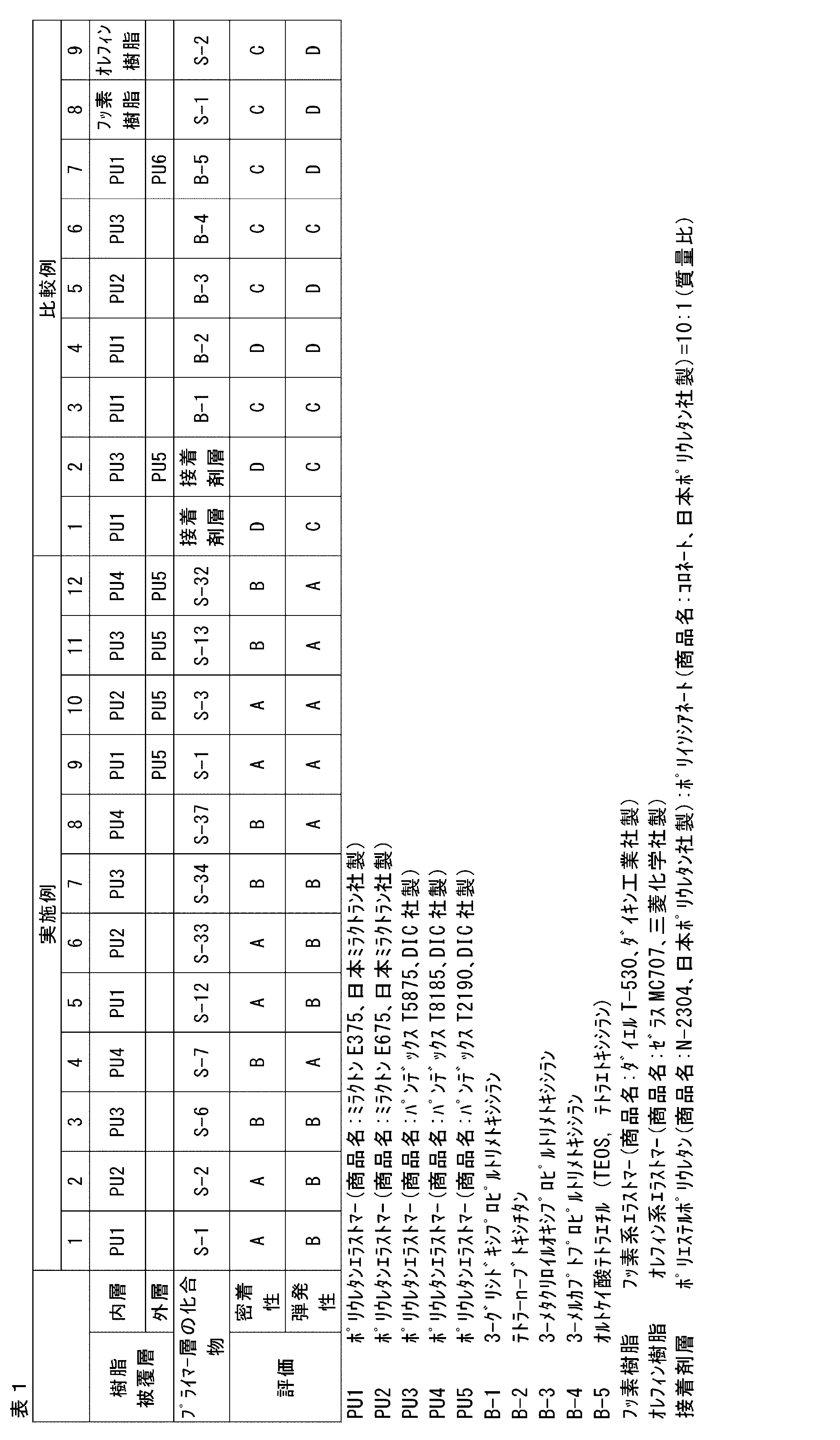
上記表1において、S-1、S-2、S-3、S-6、S-7、S-12、S-13、S-32、S-33、S-34、及びS-37は、それぞれ、上述の具体例として示した化合物S-1、S-2、S-3、S-6、S-7、S-12、S-13、S-32、S-33、S-34、及びS-37である。
表1に示されるように、可撓管基材の外周に、プライマー層に代えて、従来の接着剤層を形成し、その周りをポリウレタンエラストマーで被覆した場合、密着性と弾発性のいずれにおいても劣る結果となった(比較例1及び2)。
また、プライマー層に一般式(1)に包含されない化合物(アミノ基以外の官能基を有するカップリング剤)を用いた場合も同様に、密着性と弾発性の両特性に劣る結果となった(比較例3~7)。なお、比較例7においてプライマー層の形成に用いたオルトケイ酸テトラエチルは、ケイ素原子に結合したエトキシ基が加水分解し、水酸基を有した状態でプライマー層を構成している。
さらに、プライマー層に一般式(1)の化合物を用いた場合でも、このプライマー層に接する樹脂被覆層がポリウレタンエラストマーを含まない場合、やはり密着性と弾発性の両特性に劣っていた(比較例8及び9)。
これに対し、プライマー層に一般式(1)の化合物を用い、このプライマー層に接する樹脂被覆層にポリウレタンエラストマーを用いた場合には、得られる可撓管は基材と樹脂被覆層との密着性に優れ、また弾発性にも優れていた(実施例1~12)。
表1に示されるように、可撓管基材の外周に、プライマー層に代えて、従来の接着剤層を形成し、その周りをポリウレタンエラストマーで被覆した場合、密着性と弾発性のいずれにおいても劣る結果となった(比較例1及び2)。
また、プライマー層に一般式(1)に包含されない化合物(アミノ基以外の官能基を有するカップリング剤)を用いた場合も同様に、密着性と弾発性の両特性に劣る結果となった(比較例3~7)。なお、比較例7においてプライマー層の形成に用いたオルトケイ酸テトラエチルは、ケイ素原子に結合したエトキシ基が加水分解し、水酸基を有した状態でプライマー層を構成している。
さらに、プライマー層に一般式(1)の化合物を用いた場合でも、このプライマー層に接する樹脂被覆層がポリウレタンエラストマーを含まない場合、やはり密着性と弾発性の両特性に劣っていた(比較例8及び9)。
これに対し、プライマー層に一般式(1)の化合物を用い、このプライマー層に接する樹脂被覆層にポリウレタンエラストマーを用いた場合には、得られる可撓管は基材と樹脂被覆層との密着性に優れ、また弾発性にも優れていた(実施例1~12)。
2 電子内視鏡(内視鏡)
3 挿入部
3a 可撓管
3b アングル部
3c 先端部
5 本体操作部
6 ユニバーサルコード
11 螺旋管
11a 金属帯片
12 筒状網体
13 口金
14 可撓管基材
14a 先端側
14b 基端側
15 樹脂被覆層
16 トップコート層
17 内層
18 外層
X アングル部3b側(軟)
Y 本体操作部5側(硬)
20 連続成形機(製造装置)
21、22 押し出し部
21a スクリュー
22a スクリュー
23 ヘッド部
24 冷却部
25 搬送部
26 制御部
28 供給ドラム
29 巻取ドラム
30 ジョイント部材
31 連結可撓管基材
32 ニップル
33 ダイス
34 支持体
35、36 ゲート
37 成形通路
38 樹脂通路
39 軟質樹脂(ポリウレタンエラストマーを含む)
40 硬質樹脂
3 挿入部
3a 可撓管
3b アングル部
3c 先端部
5 本体操作部
6 ユニバーサルコード
11 螺旋管
11a 金属帯片
12 筒状網体
13 口金
14 可撓管基材
14a 先端側
14b 基端側
15 樹脂被覆層
16 トップコート層
17 内層
18 外層
X アングル部3b側(軟)
Y 本体操作部5側(硬)
20 連続成形機(製造装置)
21、22 押し出し部
21a スクリュー
22a スクリュー
23 ヘッド部
24 冷却部
25 搬送部
26 制御部
28 供給ドラム
29 巻取ドラム
30 ジョイント部材
31 連結可撓管基材
32 ニップル
33 ダイス
34 支持体
35、36 ゲート
37 成形通路
38 樹脂通路
39 軟質樹脂(ポリウレタンエラストマーを含む)
40 硬質樹脂
Claims (11)
- 金属を構成材料とする可撓管基材と、該可撓管基材の外周を覆う樹脂被覆層とを有する内視鏡用可撓管であって、
前記可撓管基材と前記樹脂被覆層との間に下記一般式(1)で表される化合物を含むプライマー層を有し、前記樹脂被覆層が、少なくともプライマー層と接する側にポリウレタンエラストマーを含む、内視鏡用可撓管。

Y1はヒドロキシ基又はアルコキシ基を示す。Y2及びY3はヒドロキシ基、アルコキシ基又はアルキル基を示す。
Lは単結合、又は、アルキレン基、アリーレン基及び-O-から選ばれる2価の基もしくは該2価の基を2つ以上組合せてなる2価の基を示す。 - 前記可撓管基材を構成する金属がステンレスである、請求項1に記載の内視鏡用可撓管。
- 前記可撓管基材を構成する金属が表面に不動態皮膜を有する、請求項1又は2に記載の内視鏡用可撓管。
- 前記樹脂被覆層が単層構造又は複層構造であり、前記プライマー層と接する層中にポリウレタンエラストマーを含む、請求項1~3のいずれか1項に記載の内視鏡用可撓管。
- 前記樹脂被覆層が2層構造であり、該2層構造の内層及び外層の厚みの割合が、前記可撓管基材の軸方向において傾斜的に変化している、請求項1~4のいずれか1項に記載の内視鏡用可撓管。
- 前記の内層及び外層の厚みの割合が、前記内視鏡用可撓管の一端において内層:外層=5:95~40:60であって、他端において内層:外層=95:5~60:40である、請求項1~5のいずれか1項に記載の内視鏡用可撓管。
- 請求項1~6のいずれか1項に記載の内視鏡用可撓管を有する内視鏡型医療機器。
- 金属を構成材料とする可撓管基材の少なくとも外周に、下記一般式(1)で表される化合物を含むプライマー層を形成する工程、及び
前記可撓管基材の外周に形成された前記プライマー層に接して、ポリウレタンエラストマーを含む樹脂を被覆することにより樹脂被覆層を形成する工程
を含む、内視鏡用可撓管の製造方法。

Y1はヒドロキシ基又はアルコキシ基を示す。Y2及びY3はヒドロキシ基、アルコキシ基又はアルキル基を示す。
Lは単結合、又は、アルキレン基、アリーレン基及び-O-から選ばれる2価の基もしくは該2価の基を2つ以上組合せてなる2価の基を示す。 - 前記樹脂被覆層が2層構造であり、該2層構造の少なくとも内層がポリウレタンエラストマーを含み、該2層構造の内層及び外層の厚みの割合が、前記可撓管基材の軸方向において傾斜的に変化している、請求項8に記載の内視鏡用可撓管の製造方法。
- 請求項8又は9に記載の内視鏡用可撓管の製造方法により内視鏡用可撓管を得る工程、及び、
得られた内視鏡用可撓管を内視鏡用型医療機器の挿入部に組み込む工程
を含む、内視鏡型医療機器の製造方法。 - 請求項1~6のいずれか1項に記載の内視鏡用可撓管を内視鏡用型医療機器の挿入部に組み込むことを含む、内視鏡型医療機器の製造方法。
Priority Applications (4)
| Application Number | Priority Date | Filing Date | Title |
|---|---|---|---|
| EP18831899.2A EP3653104B1 (en) | 2017-07-12 | 2018-07-11 | Flexible tube for endoscope, endoscopic medical device, and methods for producing these |
| CN201880045956.XA CN110868906B (zh) | 2017-07-12 | 2018-07-11 | 内窥镜用挠性管、内窥镜型医疗器械及其制造方法 |
| JP2019529758A JP6966549B2 (ja) | 2017-07-12 | 2018-07-11 | 内視鏡用可撓管、内視鏡型医療機器、及びこれらの製造方法 |
| US16/703,698 US20200100652A1 (en) | 2017-07-12 | 2019-12-04 | Flexible tube for endoscope, endoscopic medical device, and methods for producing the same |
Applications Claiming Priority (2)
| Application Number | Priority Date | Filing Date | Title |
|---|---|---|---|
| JP2017-136025 | 2017-07-12 | ||
| JP2017136025 | 2017-07-12 |
Related Child Applications (1)
| Application Number | Title | Priority Date | Filing Date |
|---|---|---|---|
| US16/703,698 Continuation US20200100652A1 (en) | 2017-07-12 | 2019-12-04 | Flexible tube for endoscope, endoscopic medical device, and methods for producing the same |
Publications (1)
| Publication Number | Publication Date |
|---|---|
| WO2019013243A1 true WO2019013243A1 (ja) | 2019-01-17 |
Family
ID=65001388
Family Applications (1)
| Application Number | Title | Priority Date | Filing Date |
|---|---|---|---|
| PCT/JP2018/026153 Ceased WO2019013243A1 (ja) | 2017-07-12 | 2018-07-11 | 内視鏡用可撓管、内視鏡型医療機器、及びこれらの製造方法 |
Country Status (5)
| Country | Link |
|---|---|
| US (1) | US20200100652A1 (ja) |
| EP (1) | EP3653104B1 (ja) |
| JP (2) | JP6966549B2 (ja) |
| CN (1) | CN110868906B (ja) |
| WO (1) | WO2019013243A1 (ja) |
Cited By (8)
| Publication number | Priority date | Publication date | Assignee | Title |
|---|---|---|---|---|
| WO2020149261A1 (ja) * | 2019-01-16 | 2020-07-23 | 富士フイルム株式会社 | 内視鏡用可撓管、内視鏡型医療機器、及びこれらの製造方法 |
| WO2020149259A1 (ja) * | 2019-01-16 | 2020-07-23 | 富士フイルム株式会社 | 内視鏡用可撓管、内視鏡型医療機器、及びこれらの製造方法 |
| JPWO2022004659A1 (ja) * | 2020-06-29 | 2022-01-06 | ||
| WO2022004657A1 (ja) * | 2020-06-29 | 2022-01-06 | 富士フイルム株式会社 | 内視鏡用可撓管、内視鏡型医療機器、及びこれらの製造方法 |
| JPWO2022070722A1 (ja) * | 2020-09-29 | 2022-04-07 | ||
| JP2023101217A (ja) * | 2022-01-07 | 2023-07-20 | Hoya株式会社 | 電極付き内視鏡システム |
| US20230292998A1 (en) * | 2020-12-24 | 2023-09-21 | Fujifilm Corporation | Flexible tube for endoscope, endoscopic medical device, and methods for producing the same |
| US12575715B2 (en) * | 2020-12-24 | 2026-03-17 | Fujifilm Corporation | Flexible tube for endoscope, endoscopic medical device, and methods for producing the same |
Families Citing this family (6)
| Publication number | Priority date | Publication date | Assignee | Title |
|---|---|---|---|---|
| EP4173547A4 (en) * | 2020-06-29 | 2024-01-17 | FUJIFILM Corporation | FLEXIBLE HOSE FOR ENDOSCOPE, ENDOSCOPIC MEDICAL DEVICE, METHOD FOR PRODUCING COATING MATERIAL FOR ENDOSCOPE AND METHOD FOR PRODUCING THE TUBE |
| CN115996661B (zh) * | 2020-06-29 | 2026-04-07 | 富士胶片株式会社 | 内窥镜用挠性管、内窥镜型医疗器材及内窥镜用挠性管基材被覆材料 |
| US20240049949A1 (en) * | 2020-12-18 | 2024-02-15 | Gyrus Acmi, Inc. D/B/A Olympus Surgical Technologies America | Direct peroral cholangioscope system with guide sheath |
| US12048419B2 (en) * | 2022-07-07 | 2024-07-30 | Hoya Corporation | Peroxide-resistant flexible endoscope, and methods of reprocessing or sterilizing such endoscope |
| WO2024048388A1 (ja) | 2022-08-30 | 2024-03-07 | 富士フイルム株式会社 | 情報処理装置、情報処理装置の作動方法、および情報処理装置の作動プログラム |
| CN119655692B (zh) * | 2025-02-18 | 2025-04-18 | 淄博晟元新材料科技有限责任公司 | 内窥镜制造工艺及其制造的内窥镜 |
Citations (8)
| Publication number | Priority date | Publication date | Assignee | Title |
|---|---|---|---|---|
| JPH10317159A (ja) * | 1997-05-22 | 1998-12-02 | Japan Energy Corp | 印刷回路用銅箔 |
| JPH1142205A (ja) | 1997-07-25 | 1999-02-16 | Olympus Optical Co Ltd | 内視鏡可撓管 |
| JP2003534440A (ja) * | 2000-05-23 | 2003-11-18 | ロード コーポレーション | 冷却液耐性および熱安定性プライマ−組成物 |
| JP2005015643A (ja) | 2003-06-26 | 2005-01-20 | Dic Bayer Polymer Ltd | 熱可塑性ポリウレタン樹脂組成物及び成形物 |
| JP2011056710A (ja) * | 2009-09-08 | 2011-03-24 | Shinoda Shoji Kk | 圧胴用ジャケットとその製造方法 |
| JP2011072391A (ja) | 2009-09-29 | 2011-04-14 | Fujifilm Corp | 内視鏡用可撓管及びその製造方法 |
| JP2015214743A (ja) * | 2014-04-24 | 2015-12-03 | 四国化成工業株式会社 | 金属の表面処理剤 |
| JP2016067566A (ja) * | 2014-09-29 | 2016-05-09 | 富士フイルム株式会社 | 内視鏡用可撓管、内視鏡用接着剤、内視鏡型医療機器、ならびに内視鏡用可撓管および内視鏡型医療機器の製造方法 |
Family Cites Families (18)
| Publication number | Priority date | Publication date | Assignee | Title |
|---|---|---|---|---|
| JPH0667376B2 (ja) * | 1985-12-26 | 1994-08-31 | 旭光学工業株式会社 | 内視鏡の可撓管 |
| US4944287A (en) * | 1988-03-29 | 1990-07-31 | Asahi Kogaku Kogyo K.K. | Flexible tube of endoscope |
| JPH05220102A (ja) * | 1992-02-13 | 1993-08-31 | Asahi Optical Co Ltd | 内視鏡の可撓管 |
| US5788714A (en) * | 1995-08-14 | 1998-08-04 | Asahi Kogaku Kogyo Kabushiki Kaisha | Flexible tube for an endoscope |
| US6860849B2 (en) * | 2000-05-08 | 2005-03-01 | Pentax Corporation | Flexible tube for an endoscope |
| JP2002224018A (ja) * | 2001-02-05 | 2002-08-13 | Asahi Optical Co Ltd | 内視鏡用可撓管 |
| JP4047069B2 (ja) * | 2002-05-21 | 2008-02-13 | ペンタックス株式会社 | 内視鏡用可撓管および内視鏡 |
| JP3824572B2 (ja) * | 2002-10-25 | 2006-09-20 | オリンパス株式会社 | 内視鏡用可撓管 |
| DE602004025130D1 (de) * | 2003-11-07 | 2010-03-04 | Kaneka Corp | Saugkatheter |
| JP2006314521A (ja) * | 2005-05-12 | 2006-11-24 | Olympus Medical Systems Corp | 内視鏡用可撓管 |
| US8231926B2 (en) * | 2007-12-21 | 2012-07-31 | Innovatech, Llc | Marked precoated medical device and method of manufacturing same |
| JP5453156B2 (ja) * | 2010-03-31 | 2014-03-26 | 富士フイルム株式会社 | 内視鏡の可撓管及びその製造方法 |
| EP2576471B1 (en) * | 2010-05-25 | 2017-10-25 | 3M Innovative Properties Company | Antimicrobial coated medical articles |
| EP2402051B1 (en) * | 2010-06-30 | 2019-10-02 | Asahi Intecc Co., Ltd. | Medical guide wire |
| US8480597B2 (en) * | 2010-09-13 | 2013-07-09 | Abbott Laboratories | Color coded guide wire and methods of making same |
| JP5952119B2 (ja) * | 2012-03-23 | 2016-07-13 | 富士フイルム株式会社 | 導電性部材およびその製造方法 |
| WO2014157375A1 (ja) * | 2013-03-27 | 2014-10-02 | 富士フイルム株式会社 | 内視鏡用可撓管およびその製造方法 |
| JP6329804B2 (ja) * | 2014-04-07 | 2018-05-23 | 富士フイルム株式会社 | 可撓管、これを用いた内視鏡型医療機器、その接着剤、可撓管および内視鏡型医療機器の製造方法 |
-
2018
- 2018-07-11 EP EP18831899.2A patent/EP3653104B1/en active Active
- 2018-07-11 JP JP2019529758A patent/JP6966549B2/ja active Active
- 2018-07-11 CN CN201880045956.XA patent/CN110868906B/zh active Active
- 2018-07-11 WO PCT/JP2018/026153 patent/WO2019013243A1/ja not_active Ceased
-
2019
- 2019-12-04 US US16/703,698 patent/US20200100652A1/en not_active Abandoned
-
2021
- 2021-06-15 JP JP2021099583A patent/JP2021166723A/ja not_active Withdrawn
Patent Citations (8)
| Publication number | Priority date | Publication date | Assignee | Title |
|---|---|---|---|---|
| JPH10317159A (ja) * | 1997-05-22 | 1998-12-02 | Japan Energy Corp | 印刷回路用銅箔 |
| JPH1142205A (ja) | 1997-07-25 | 1999-02-16 | Olympus Optical Co Ltd | 内視鏡可撓管 |
| JP2003534440A (ja) * | 2000-05-23 | 2003-11-18 | ロード コーポレーション | 冷却液耐性および熱安定性プライマ−組成物 |
| JP2005015643A (ja) | 2003-06-26 | 2005-01-20 | Dic Bayer Polymer Ltd | 熱可塑性ポリウレタン樹脂組成物及び成形物 |
| JP2011056710A (ja) * | 2009-09-08 | 2011-03-24 | Shinoda Shoji Kk | 圧胴用ジャケットとその製造方法 |
| JP2011072391A (ja) | 2009-09-29 | 2011-04-14 | Fujifilm Corp | 内視鏡用可撓管及びその製造方法 |
| JP2015214743A (ja) * | 2014-04-24 | 2015-12-03 | 四国化成工業株式会社 | 金属の表面処理剤 |
| JP2016067566A (ja) * | 2014-09-29 | 2016-05-09 | 富士フイルム株式会社 | 内視鏡用可撓管、内視鏡用接着剤、内視鏡型医療機器、ならびに内視鏡用可撓管および内視鏡型医療機器の製造方法 |
Non-Patent Citations (1)
| Title |
|---|
| See also references of EP3653104A4 |
Cited By (19)
| Publication number | Priority date | Publication date | Assignee | Title |
|---|---|---|---|---|
| WO2020149261A1 (ja) * | 2019-01-16 | 2020-07-23 | 富士フイルム株式会社 | 内視鏡用可撓管、内視鏡型医療機器、及びこれらの製造方法 |
| WO2020149259A1 (ja) * | 2019-01-16 | 2020-07-23 | 富士フイルム株式会社 | 内視鏡用可撓管、内視鏡型医療機器、及びこれらの製造方法 |
| US12122121B2 (en) | 2019-01-16 | 2024-10-22 | Fujifilm Corporation | Flexible tube for endoscope, endoscopic medical device, and methods for producing the same |
| CN115942897A (zh) * | 2020-06-29 | 2023-04-07 | 富士胶片株式会社 | 内窥镜用挠性管、内窥镜型医疗器材及内窥镜用挠性管基材被覆用材料 |
| JP7434555B2 (ja) | 2020-06-29 | 2024-02-20 | 富士フイルム株式会社 | 内視鏡用可撓管、内視鏡型医療機器、及びこれらの製造方法 |
| WO2022004659A1 (ja) * | 2020-06-29 | 2022-01-06 | 富士フイルム株式会社 | 内視鏡用可撓管、内視鏡型医療機器、及び内視鏡用可撓管基材被覆用材料 |
| US12390248B2 (en) | 2020-06-29 | 2025-08-19 | Fujifilm Corporation | Endoscopic flexible tube, endoscopic medical apparatus, and endoscopic-flexible-tube-base-covering material |
| JPWO2022004659A1 (ja) * | 2020-06-29 | 2022-01-06 | ||
| WO2022004657A1 (ja) * | 2020-06-29 | 2022-01-06 | 富士フイルム株式会社 | 内視鏡用可撓管、内視鏡型医療機器、及びこれらの製造方法 |
| JP7274052B2 (ja) | 2020-06-29 | 2023-05-15 | 富士フイルム株式会社 | 内視鏡用可撓管、内視鏡型医療機器、及び内視鏡用可撓管基材被覆用材料 |
| JPWO2022004657A1 (ja) * | 2020-06-29 | 2022-01-06 | ||
| JP7461493B2 (ja) | 2020-09-29 | 2024-04-03 | 富士フイルム株式会社 | 内視鏡用可撓管、内視鏡型医療機器、及びこれらの製造方法 |
| WO2022070722A1 (ja) | 2020-09-29 | 2022-04-07 | 富士フイルム株式会社 | 内視鏡用可撓管、内視鏡型医療機器、及びこれらの製造方法 |
| JPWO2022070722A1 (ja) * | 2020-09-29 | 2022-04-07 | ||
| US20230292998A1 (en) * | 2020-12-24 | 2023-09-21 | Fujifilm Corporation | Flexible tube for endoscope, endoscopic medical device, and methods for producing the same |
| US12575715B2 (en) * | 2020-12-24 | 2026-03-17 | Fujifilm Corporation | Flexible tube for endoscope, endoscopic medical device, and methods for producing the same |
| US12611091B2 (en) * | 2020-12-24 | 2026-04-28 | Fujifilm Corporation | Flexible tube for endoscope, endoscopic medical device, and methods for producing the same |
| JP2023101217A (ja) * | 2022-01-07 | 2023-07-20 | Hoya株式会社 | 電極付き内視鏡システム |
| JP7621293B2 (ja) | 2022-01-07 | 2025-01-24 | Hoya株式会社 | 電極付き内視鏡システム |
Also Published As
| Publication number | Publication date |
|---|---|
| US20200100652A1 (en) | 2020-04-02 |
| CN110868906B (zh) | 2022-03-08 |
| JPWO2019013243A1 (ja) | 2020-02-27 |
| CN110868906A (zh) | 2020-03-06 |
| JP6966549B2 (ja) | 2021-11-17 |
| EP3653104B1 (en) | 2021-08-25 |
| EP3653104A1 (en) | 2020-05-20 |
| JP2021166723A (ja) | 2021-10-21 |
| EP3653104A4 (en) | 2020-07-29 |
Similar Documents
| Publication | Publication Date | Title |
|---|---|---|
| JP6966549B2 (ja) | 内視鏡用可撓管、内視鏡型医療機器、及びこれらの製造方法 | |
| JP6110827B2 (ja) | 内視鏡用可撓管、内視鏡用接着剤、内視鏡型医療機器、ならびに内視鏡用可撓管および内視鏡型医療機器の製造方法 | |
| WO2014157375A1 (ja) | 内視鏡用可撓管およびその製造方法 | |
| JP5991951B2 (ja) | 内視鏡用可撓管および内視鏡型医療機器 | |
| JP6072089B2 (ja) | 可撓管、内視鏡型医療機器およびトップコート層用の樹脂組成物 | |
| JP6329804B2 (ja) | 可撓管、これを用いた内視鏡型医療機器、その接着剤、可撓管および内視鏡型医療機器の製造方法 | |
| JP6047440B2 (ja) | 内視鏡用可撓管およびその製造方法 | |
| JP7461493B2 (ja) | 内視鏡用可撓管、内視鏡型医療機器、及びこれらの製造方法 | |
| JP2016209649A (ja) | 内視鏡用可撓管および内視鏡型医療機器 | |
| JP2002224021A (ja) | 内視鏡用可撓管 | |
| JP7425850B2 (ja) | 内視鏡用可撓管、内視鏡型医療機器、及びこれらの製造方法 | |
| US12575715B2 (en) | Flexible tube for endoscope, endoscopic medical device, and methods for producing the same | |
| JP7697976B2 (ja) | 内視鏡用可撓管、内視鏡型医療機器、及びこれらの製造方法 | |
| JP2002224018A (ja) | 内視鏡用可撓管 | |
| CN113227872B (zh) | 内窥镜用挠性管、内窥镜型医疗器械、及其制造方法 | |
| JP2002065590A (ja) | 内視鏡用可撓管 |
Legal Events
| Date | Code | Title | Description |
|---|---|---|---|
| 121 | Ep: the epo has been informed by wipo that ep was designated in this application |
Ref document number: 18831899 Country of ref document: EP Kind code of ref document: A1 |
|
| DPE1 | Request for preliminary examination filed after expiration of 19th month from priority date (pct application filed from 20040101) | ||
| ENP | Entry into the national phase |
Ref document number: 2019529758 Country of ref document: JP Kind code of ref document: A |
|
| NENP | Non-entry into the national phase |
Ref country code: DE |
|
| ENP | Entry into the national phase |
Ref document number: 2018831899 Country of ref document: EP Effective date: 20200212 |