WO2019013347A1 - 方向性電磁鋼板、及び方向性電磁鋼板の製造方法 - Google Patents
方向性電磁鋼板、及び方向性電磁鋼板の製造方法 Download PDFInfo
- Publication number
- WO2019013347A1 WO2019013347A1 PCT/JP2018/026611 JP2018026611W WO2019013347A1 WO 2019013347 A1 WO2019013347 A1 WO 2019013347A1 JP 2018026611 W JP2018026611 W JP 2018026611W WO 2019013347 A1 WO2019013347 A1 WO 2019013347A1
- Authority
- WO
- WIPO (PCT)
- Prior art keywords
- steel sheet
- intermediate layer
- annealing
- grain
- oriented electrical
- Prior art date
- Legal status (The legal status is an assumption and is not a legal conclusion. Google has not performed a legal analysis and makes no representation as to the accuracy of the status listed.)
- Ceased
Links
Images



Classifications
-
- C—CHEMISTRY; METALLURGY
- C21—METALLURGY OF IRON
- C21D—MODIFYING THE PHYSICAL STRUCTURE OF FERROUS METALS; GENERAL DEVICES FOR HEAT TREATMENT OF FERROUS OR NON-FERROUS METALS OR ALLOYS; MAKING METAL MALLEABLE, e.g. BY DECARBURISATION OR TEMPERING
- C21D8/00—Modifying the physical properties of ferrous metals or ferrous alloys by deformation combined with, or followed by, heat treatment
- C21D8/12—Modifying the physical properties of ferrous metals or ferrous alloys by deformation combined with, or followed by, heat treatment during manufacturing of articles with special electromagnetic properties
- C21D8/1216—Modifying the physical properties of ferrous metals or ferrous alloys by deformation combined with, or followed by, heat treatment during manufacturing of articles with special electromagnetic properties characterised by the working steps
- C21D8/1222—Hot rolling
-
- C—CHEMISTRY; METALLURGY
- C23—COATING METALLIC MATERIAL; COATING MATERIAL WITH METALLIC MATERIAL; CHEMICAL SURFACE TREATMENT; DIFFUSION TREATMENT OF METALLIC MATERIAL; COATING BY VACUUM EVAPORATION, BY SPUTTERING, BY ION IMPLANTATION OR BY CHEMICAL VAPOUR DEPOSITION, IN GENERAL; INHIBITING CORROSION OF METALLIC MATERIAL OR INCRUSTATION IN GENERAL
- C23C—COATING METALLIC MATERIAL; COATING MATERIAL WITH METALLIC MATERIAL; SURFACE TREATMENT OF METALLIC MATERIAL BY DIFFUSION INTO THE SURFACE, BY CHEMICAL CONVERSION OR SUBSTITUTION; COATING BY VACUUM EVAPORATION, BY SPUTTERING, BY ION IMPLANTATION OR BY CHEMICAL VAPOUR DEPOSITION, IN GENERAL
- C23C22/00—Chemical surface treatment of metallic material by reaction of the surface with a reactive liquid, leaving reaction products of surface material in the coating, e.g. conversion coatings, passivation of metals
- C23C22/78—Pretreatment of the material to be coated
-
- C—CHEMISTRY; METALLURGY
- C21—METALLURGY OF IRON
- C21D—MODIFYING THE PHYSICAL STRUCTURE OF FERROUS METALS; GENERAL DEVICES FOR HEAT TREATMENT OF FERROUS OR NON-FERROUS METALS OR ALLOYS; MAKING METAL MALLEABLE, e.g. BY DECARBURISATION OR TEMPERING
- C21D8/00—Modifying the physical properties of ferrous metals or ferrous alloys by deformation combined with, or followed by, heat treatment
- C21D8/12—Modifying the physical properties of ferrous metals or ferrous alloys by deformation combined with, or followed by, heat treatment during manufacturing of articles with special electromagnetic properties
-
- C—CHEMISTRY; METALLURGY
- C21—METALLURGY OF IRON
- C21D—MODIFYING THE PHYSICAL STRUCTURE OF FERROUS METALS; GENERAL DEVICES FOR HEAT TREATMENT OF FERROUS OR NON-FERROUS METALS OR ALLOYS; MAKING METAL MALLEABLE, e.g. BY DECARBURISATION OR TEMPERING
- C21D8/00—Modifying the physical properties of ferrous metals or ferrous alloys by deformation combined with, or followed by, heat treatment
- C21D8/12—Modifying the physical properties of ferrous metals or ferrous alloys by deformation combined with, or followed by, heat treatment during manufacturing of articles with special electromagnetic properties
- C21D8/1216—Modifying the physical properties of ferrous metals or ferrous alloys by deformation combined with, or followed by, heat treatment during manufacturing of articles with special electromagnetic properties characterised by the working steps
- C21D8/1233—Cold rolling
-
- C—CHEMISTRY; METALLURGY
- C21—METALLURGY OF IRON
- C21D—MODIFYING THE PHYSICAL STRUCTURE OF FERROUS METALS; GENERAL DEVICES FOR HEAT TREATMENT OF FERROUS OR NON-FERROUS METALS OR ALLOYS; MAKING METAL MALLEABLE, e.g. BY DECARBURISATION OR TEMPERING
- C21D8/00—Modifying the physical properties of ferrous metals or ferrous alloys by deformation combined with, or followed by, heat treatment
- C21D8/12—Modifying the physical properties of ferrous metals or ferrous alloys by deformation combined with, or followed by, heat treatment during manufacturing of articles with special electromagnetic properties
- C21D8/1244—Modifying the physical properties of ferrous metals or ferrous alloys by deformation combined with, or followed by, heat treatment during manufacturing of articles with special electromagnetic properties characterised by the heat treatment
- C21D8/1255—Modifying the physical properties of ferrous metals or ferrous alloys by deformation combined with, or followed by, heat treatment during manufacturing of articles with special electromagnetic properties characterised by the heat treatment with diffusion of elements, e.g. decarburising, nitriding
-
- C—CHEMISTRY; METALLURGY
- C21—METALLURGY OF IRON
- C21D—MODIFYING THE PHYSICAL STRUCTURE OF FERROUS METALS; GENERAL DEVICES FOR HEAT TREATMENT OF FERROUS OR NON-FERROUS METALS OR ALLOYS; MAKING METAL MALLEABLE, e.g. BY DECARBURISATION OR TEMPERING
- C21D8/00—Modifying the physical properties of ferrous metals or ferrous alloys by deformation combined with, or followed by, heat treatment
- C21D8/12—Modifying the physical properties of ferrous metals or ferrous alloys by deformation combined with, or followed by, heat treatment during manufacturing of articles with special electromagnetic properties
- C21D8/1277—Modifying the physical properties of ferrous metals or ferrous alloys by deformation combined with, or followed by, heat treatment during manufacturing of articles with special electromagnetic properties involving a particular surface treatment
- C21D8/1283—Application of a separating or insulating coating
-
- C—CHEMISTRY; METALLURGY
- C21—METALLURGY OF IRON
- C21D—MODIFYING THE PHYSICAL STRUCTURE OF FERROUS METALS; GENERAL DEVICES FOR HEAT TREATMENT OF FERROUS OR NON-FERROUS METALS OR ALLOYS; MAKING METAL MALLEABLE, e.g. BY DECARBURISATION OR TEMPERING
- C21D9/00—Heat treatment, e.g. annealing, hardening, quenching or tempering, adapted for particular articles; Furnaces therefor
- C21D9/46—Heat treatment, e.g. annealing, hardening, quenching or tempering, adapted for particular articles; Furnaces therefor for sheet metals
-
- C—CHEMISTRY; METALLURGY
- C22—METALLURGY; FERROUS OR NON-FERROUS ALLOYS; TREATMENT OF ALLOYS OR NON-FERROUS METALS
- C22C—ALLOYS
- C22C38/00—Ferrous alloys, e.g. steel alloys
-
- C—CHEMISTRY; METALLURGY
- C22—METALLURGY; FERROUS OR NON-FERROUS ALLOYS; TREATMENT OF ALLOYS OR NON-FERROUS METALS
- C22C—ALLOYS
- C22C38/00—Ferrous alloys, e.g. steel alloys
- C22C38/001—Ferrous alloys, e.g. steel alloys containing N
-
- C—CHEMISTRY; METALLURGY
- C22—METALLURGY; FERROUS OR NON-FERROUS ALLOYS; TREATMENT OF ALLOYS OR NON-FERROUS METALS
- C22C—ALLOYS
- C22C38/00—Ferrous alloys, e.g. steel alloys
- C22C38/004—Very low carbon steels, i.e. having a carbon content of less than 0,01%
-
- C—CHEMISTRY; METALLURGY
- C22—METALLURGY; FERROUS OR NON-FERROUS ALLOYS; TREATMENT OF ALLOYS OR NON-FERROUS METALS
- C22C—ALLOYS
- C22C38/00—Ferrous alloys, e.g. steel alloys
- C22C38/02—Ferrous alloys, e.g. steel alloys containing silicon
-
- C—CHEMISTRY; METALLURGY
- C22—METALLURGY; FERROUS OR NON-FERROUS ALLOYS; TREATMENT OF ALLOYS OR NON-FERROUS METALS
- C22C—ALLOYS
- C22C38/00—Ferrous alloys, e.g. steel alloys
- C22C38/04—Ferrous alloys, e.g. steel alloys containing manganese
-
- C—CHEMISTRY; METALLURGY
- C22—METALLURGY; FERROUS OR NON-FERROUS ALLOYS; TREATMENT OF ALLOYS OR NON-FERROUS METALS
- C22C—ALLOYS
- C22C38/00—Ferrous alloys, e.g. steel alloys
- C22C38/06—Ferrous alloys, e.g. steel alloys containing aluminium
-
- C—CHEMISTRY; METALLURGY
- C22—METALLURGY; FERROUS OR NON-FERROUS ALLOYS; TREATMENT OF ALLOYS OR NON-FERROUS METALS
- C22C—ALLOYS
- C22C38/00—Ferrous alloys, e.g. steel alloys
- C22C38/60—Ferrous alloys, e.g. steel alloys containing lead, selenium, tellurium, or antimony, or more than 0.04% by weight of sulfur
-
- C—CHEMISTRY; METALLURGY
- C23—COATING METALLIC MATERIAL; COATING MATERIAL WITH METALLIC MATERIAL; CHEMICAL SURFACE TREATMENT; DIFFUSION TREATMENT OF METALLIC MATERIAL; COATING BY VACUUM EVAPORATION, BY SPUTTERING, BY ION IMPLANTATION OR BY CHEMICAL VAPOUR DEPOSITION, IN GENERAL; INHIBITING CORROSION OF METALLIC MATERIAL OR INCRUSTATION IN GENERAL
- C23C—COATING METALLIC MATERIAL; COATING MATERIAL WITH METALLIC MATERIAL; SURFACE TREATMENT OF METALLIC MATERIAL BY DIFFUSION INTO THE SURFACE, BY CHEMICAL CONVERSION OR SUBSTITUTION; COATING BY VACUUM EVAPORATION, BY SPUTTERING, BY ION IMPLANTATION OR BY CHEMICAL VAPOUR DEPOSITION, IN GENERAL
- C23C22/00—Chemical surface treatment of metallic material by reaction of the surface with a reactive liquid, leaving reaction products of surface material in the coating, e.g. conversion coatings, passivation of metals
-
- C—CHEMISTRY; METALLURGY
- C23—COATING METALLIC MATERIAL; COATING MATERIAL WITH METALLIC MATERIAL; CHEMICAL SURFACE TREATMENT; DIFFUSION TREATMENT OF METALLIC MATERIAL; COATING BY VACUUM EVAPORATION, BY SPUTTERING, BY ION IMPLANTATION OR BY CHEMICAL VAPOUR DEPOSITION, IN GENERAL; INHIBITING CORROSION OF METALLIC MATERIAL OR INCRUSTATION IN GENERAL
- C23C—COATING METALLIC MATERIAL; COATING MATERIAL WITH METALLIC MATERIAL; SURFACE TREATMENT OF METALLIC MATERIAL BY DIFFUSION INTO THE SURFACE, BY CHEMICAL CONVERSION OR SUBSTITUTION; COATING BY VACUUM EVAPORATION, BY SPUTTERING, BY ION IMPLANTATION OR BY CHEMICAL VAPOUR DEPOSITION, IN GENERAL
- C23C22/00—Chemical surface treatment of metallic material by reaction of the surface with a reactive liquid, leaving reaction products of surface material in the coating, e.g. conversion coatings, passivation of metals
- C23C22/05—Chemical surface treatment of metallic material by reaction of the surface with a reactive liquid, leaving reaction products of surface material in the coating, e.g. conversion coatings, passivation of metals using aqueous solutions
-
- C—CHEMISTRY; METALLURGY
- C23—COATING METALLIC MATERIAL; COATING MATERIAL WITH METALLIC MATERIAL; CHEMICAL SURFACE TREATMENT; DIFFUSION TREATMENT OF METALLIC MATERIAL; COATING BY VACUUM EVAPORATION, BY SPUTTERING, BY ION IMPLANTATION OR BY CHEMICAL VAPOUR DEPOSITION, IN GENERAL; INHIBITING CORROSION OF METALLIC MATERIAL OR INCRUSTATION IN GENERAL
- C23C—COATING METALLIC MATERIAL; COATING MATERIAL WITH METALLIC MATERIAL; SURFACE TREATMENT OF METALLIC MATERIAL BY DIFFUSION INTO THE SURFACE, BY CHEMICAL CONVERSION OR SUBSTITUTION; COATING BY VACUUM EVAPORATION, BY SPUTTERING, BY ION IMPLANTATION OR BY CHEMICAL VAPOUR DEPOSITION, IN GENERAL
- C23C22/00—Chemical surface treatment of metallic material by reaction of the surface with a reactive liquid, leaving reaction products of surface material in the coating, e.g. conversion coatings, passivation of metals
- C23C22/05—Chemical surface treatment of metallic material by reaction of the surface with a reactive liquid, leaving reaction products of surface material in the coating, e.g. conversion coatings, passivation of metals using aqueous solutions
- C23C22/06—Chemical surface treatment of metallic material by reaction of the surface with a reactive liquid, leaving reaction products of surface material in the coating, e.g. conversion coatings, passivation of metals using aqueous solutions using aqueous acidic solutions with pH less than 6
-
- C—CHEMISTRY; METALLURGY
- C23—COATING METALLIC MATERIAL; COATING MATERIAL WITH METALLIC MATERIAL; CHEMICAL SURFACE TREATMENT; DIFFUSION TREATMENT OF METALLIC MATERIAL; COATING BY VACUUM EVAPORATION, BY SPUTTERING, BY ION IMPLANTATION OR BY CHEMICAL VAPOUR DEPOSITION, IN GENERAL; INHIBITING CORROSION OF METALLIC MATERIAL OR INCRUSTATION IN GENERAL
- C23C—COATING METALLIC MATERIAL; COATING MATERIAL WITH METALLIC MATERIAL; SURFACE TREATMENT OF METALLIC MATERIAL BY DIFFUSION INTO THE SURFACE, BY CHEMICAL CONVERSION OR SUBSTITUTION; COATING BY VACUUM EVAPORATION, BY SPUTTERING, BY ION IMPLANTATION OR BY CHEMICAL VAPOUR DEPOSITION, IN GENERAL
- C23C22/00—Chemical surface treatment of metallic material by reaction of the surface with a reactive liquid, leaving reaction products of surface material in the coating, e.g. conversion coatings, passivation of metals
- C23C22/05—Chemical surface treatment of metallic material by reaction of the surface with a reactive liquid, leaving reaction products of surface material in the coating, e.g. conversion coatings, passivation of metals using aqueous solutions
- C23C22/06—Chemical surface treatment of metallic material by reaction of the surface with a reactive liquid, leaving reaction products of surface material in the coating, e.g. conversion coatings, passivation of metals using aqueous solutions using aqueous acidic solutions with pH less than 6
- C23C22/07—Chemical surface treatment of metallic material by reaction of the surface with a reactive liquid, leaving reaction products of surface material in the coating, e.g. conversion coatings, passivation of metals using aqueous solutions using aqueous acidic solutions with pH less than 6 containing phosphates
-
- C—CHEMISTRY; METALLURGY
- C23—COATING METALLIC MATERIAL; COATING MATERIAL WITH METALLIC MATERIAL; CHEMICAL SURFACE TREATMENT; DIFFUSION TREATMENT OF METALLIC MATERIAL; COATING BY VACUUM EVAPORATION, BY SPUTTERING, BY ION IMPLANTATION OR BY CHEMICAL VAPOUR DEPOSITION, IN GENERAL; INHIBITING CORROSION OF METALLIC MATERIAL OR INCRUSTATION IN GENERAL
- C23C—COATING METALLIC MATERIAL; COATING MATERIAL WITH METALLIC MATERIAL; SURFACE TREATMENT OF METALLIC MATERIAL BY DIFFUSION INTO THE SURFACE, BY CHEMICAL CONVERSION OR SUBSTITUTION; COATING BY VACUUM EVAPORATION, BY SPUTTERING, BY ION IMPLANTATION OR BY CHEMICAL VAPOUR DEPOSITION, IN GENERAL
- C23C22/00—Chemical surface treatment of metallic material by reaction of the surface with a reactive liquid, leaving reaction products of surface material in the coating, e.g. conversion coatings, passivation of metals
- C23C22/73—Chemical surface treatment of metallic material by reaction of the surface with a reactive liquid, leaving reaction products of surface material in the coating, e.g. conversion coatings, passivation of metals characterised by the process
- C23C22/74—Chemical surface treatment of metallic material by reaction of the surface with a reactive liquid, leaving reaction products of surface material in the coating, e.g. conversion coatings, passivation of metals characterised by the process for obtaining burned-in conversion coatings
-
- C—CHEMISTRY; METALLURGY
- C23—COATING METALLIC MATERIAL; COATING MATERIAL WITH METALLIC MATERIAL; CHEMICAL SURFACE TREATMENT; DIFFUSION TREATMENT OF METALLIC MATERIAL; COATING BY VACUUM EVAPORATION, BY SPUTTERING, BY ION IMPLANTATION OR BY CHEMICAL VAPOUR DEPOSITION, IN GENERAL; INHIBITING CORROSION OF METALLIC MATERIAL OR INCRUSTATION IN GENERAL
- C23C—COATING METALLIC MATERIAL; COATING MATERIAL WITH METALLIC MATERIAL; SURFACE TREATMENT OF METALLIC MATERIAL BY DIFFUSION INTO THE SURFACE, BY CHEMICAL CONVERSION OR SUBSTITUTION; COATING BY VACUUM EVAPORATION, BY SPUTTERING, BY ION IMPLANTATION OR BY CHEMICAL VAPOUR DEPOSITION, IN GENERAL
- C23C28/00—Coating for obtaining at least two superposed coatings either by methods not provided for in a single one of groups C23C2/00 - C23C26/00 or by combinations of methods provided for in subclasses C23C and C25C or C25D
-
- C—CHEMISTRY; METALLURGY
- C23—COATING METALLIC MATERIAL; COATING MATERIAL WITH METALLIC MATERIAL; CHEMICAL SURFACE TREATMENT; DIFFUSION TREATMENT OF METALLIC MATERIAL; COATING BY VACUUM EVAPORATION, BY SPUTTERING, BY ION IMPLANTATION OR BY CHEMICAL VAPOUR DEPOSITION, IN GENERAL; INHIBITING CORROSION OF METALLIC MATERIAL OR INCRUSTATION IN GENERAL
- C23C—COATING METALLIC MATERIAL; COATING MATERIAL WITH METALLIC MATERIAL; SURFACE TREATMENT OF METALLIC MATERIAL BY DIFFUSION INTO THE SURFACE, BY CHEMICAL CONVERSION OR SUBSTITUTION; COATING BY VACUUM EVAPORATION, BY SPUTTERING, BY ION IMPLANTATION OR BY CHEMICAL VAPOUR DEPOSITION, IN GENERAL
- C23C28/00—Coating for obtaining at least two superposed coatings either by methods not provided for in a single one of groups C23C2/00 - C23C26/00 or by combinations of methods provided for in subclasses C23C and C25C or C25D
- C23C28/04—Coating for obtaining at least two superposed coatings either by methods not provided for in a single one of groups C23C2/00 - C23C26/00 or by combinations of methods provided for in subclasses C23C and C25C or C25D only coatings of inorganic non-metallic material
-
- C—CHEMISTRY; METALLURGY
- C23—COATING METALLIC MATERIAL; COATING MATERIAL WITH METALLIC MATERIAL; CHEMICAL SURFACE TREATMENT; DIFFUSION TREATMENT OF METALLIC MATERIAL; COATING BY VACUUM EVAPORATION, BY SPUTTERING, BY ION IMPLANTATION OR BY CHEMICAL VAPOUR DEPOSITION, IN GENERAL; INHIBITING CORROSION OF METALLIC MATERIAL OR INCRUSTATION IN GENERAL
- C23C—COATING METALLIC MATERIAL; COATING MATERIAL WITH METALLIC MATERIAL; SURFACE TREATMENT OF METALLIC MATERIAL BY DIFFUSION INTO THE SURFACE, BY CHEMICAL CONVERSION OR SUBSTITUTION; COATING BY VACUUM EVAPORATION, BY SPUTTERING, BY ION IMPLANTATION OR BY CHEMICAL VAPOUR DEPOSITION, IN GENERAL
- C23C8/00—Solid state diffusion of only non-metal elements into metallic material surfaces; Chemical surface treatment of metallic material by reaction of the surface with a reactive gas, leaving reaction products of surface material in the coating, e.g. conversion coatings, passivation of metals
- C23C8/06—Solid state diffusion of only non-metal elements into metallic material surfaces; Chemical surface treatment of metallic material by reaction of the surface with a reactive gas, leaving reaction products of surface material in the coating, e.g. conversion coatings, passivation of metals using gases
- C23C8/08—Solid state diffusion of only non-metal elements into metallic material surfaces; Chemical surface treatment of metallic material by reaction of the surface with a reactive gas, leaving reaction products of surface material in the coating, e.g. conversion coatings, passivation of metals using gases only one element being applied
- C23C8/10—Oxidising
- C23C8/12—Oxidising using elemental oxygen or ozone
- C23C8/14—Oxidising of ferrous surfaces
-
- C—CHEMISTRY; METALLURGY
- C25—ELECTROLYTIC OR ELECTROPHORETIC PROCESSES; APPARATUS THEREFOR
- C25F—PROCESSES FOR THE ELECTROLYTIC REMOVAL OF MATERIALS FROM OBJECTS; APPARATUS THEREFOR
- C25F3/00—Electrolytic etching or polishing
- C25F3/16—Polishing
- C25F3/22—Polishing of heavy metals
- C25F3/24—Polishing of heavy metals of iron or steel
-
- H—ELECTRICITY
- H01—ELECTRIC ELEMENTS
- H01F—MAGNETS; INDUCTANCES; TRANSFORMERS; SELECTION OF MATERIALS FOR THEIR MAGNETIC PROPERTIES
- H01F1/00—Magnets or magnetic bodies characterised by the magnetic materials therefor; Selection of materials for their magnetic properties
- H01F1/01—Magnets or magnetic bodies characterised by the magnetic materials therefor; Selection of materials for their magnetic properties of inorganic materials
- H01F1/03—Magnets or magnetic bodies characterised by the magnetic materials therefor; Selection of materials for their magnetic properties of inorganic materials characterised by their coercivity
- H01F1/12—Magnets or magnetic bodies characterised by the magnetic materials therefor; Selection of materials for their magnetic properties of inorganic materials characterised by their coercivity of soft-magnetic materials
- H01F1/14—Magnets or magnetic bodies characterised by the magnetic materials therefor; Selection of materials for their magnetic properties of inorganic materials characterised by their coercivity of soft-magnetic materials metals or alloys
- H01F1/147—Alloys characterised by their composition
-
- H—ELECTRICITY
- H01—ELECTRIC ELEMENTS
- H01F—MAGNETS; INDUCTANCES; TRANSFORMERS; SELECTION OF MATERIALS FOR THEIR MAGNETIC PROPERTIES
- H01F1/00—Magnets or magnetic bodies characterised by the magnetic materials therefor; Selection of materials for their magnetic properties
- H01F1/01—Magnets or magnetic bodies characterised by the magnetic materials therefor; Selection of materials for their magnetic properties of inorganic materials
- H01F1/03—Magnets or magnetic bodies characterised by the magnetic materials therefor; Selection of materials for their magnetic properties of inorganic materials characterised by their coercivity
- H01F1/12—Magnets or magnetic bodies characterised by the magnetic materials therefor; Selection of materials for their magnetic properties of inorganic materials characterised by their coercivity of soft-magnetic materials
- H01F1/14—Magnets or magnetic bodies characterised by the magnetic materials therefor; Selection of materials for their magnetic properties of inorganic materials characterised by their coercivity of soft-magnetic materials metals or alloys
- H01F1/16—Magnets or magnetic bodies characterised by the magnetic materials therefor; Selection of materials for their magnetic properties of inorganic materials characterised by their coercivity of soft-magnetic materials metals or alloys in the form of sheets
-
- C—CHEMISTRY; METALLURGY
- C23—COATING METALLIC MATERIAL; COATING MATERIAL WITH METALLIC MATERIAL; CHEMICAL SURFACE TREATMENT; DIFFUSION TREATMENT OF METALLIC MATERIAL; COATING BY VACUUM EVAPORATION, BY SPUTTERING, BY ION IMPLANTATION OR BY CHEMICAL VAPOUR DEPOSITION, IN GENERAL; INHIBITING CORROSION OF METALLIC MATERIAL OR INCRUSTATION IN GENERAL
- C23C—COATING METALLIC MATERIAL; COATING MATERIAL WITH METALLIC MATERIAL; SURFACE TREATMENT OF METALLIC MATERIAL BY DIFFUSION INTO THE SURFACE, BY CHEMICAL CONVERSION OR SUBSTITUTION; COATING BY VACUUM EVAPORATION, BY SPUTTERING, BY ION IMPLANTATION OR BY CHEMICAL VAPOUR DEPOSITION, IN GENERAL
- C23C18/00—Chemical coating by decomposition of either liquid compounds or solutions of the coating forming compounds, without leaving reaction products of surface material in the coating; Contact plating
- C23C18/02—Chemical coating by decomposition of either liquid compounds or solutions of the coating forming compounds, without leaving reaction products of surface material in the coating; Contact plating by thermal decomposition
- C23C18/12—Chemical coating by decomposition of either liquid compounds or solutions of the coating forming compounds, without leaving reaction products of surface material in the coating; Contact plating by thermal decomposition characterised by the deposition of inorganic material other than metallic material
- C23C18/1204—Chemical coating by decomposition of either liquid compounds or solutions of the coating forming compounds, without leaving reaction products of surface material in the coating; Contact plating by thermal decomposition characterised by the deposition of inorganic material other than metallic material inorganic material, e.g. non-oxide and non-metallic such as sulfides, nitrides based compounds
- C23C18/1208—Oxides, e.g. ceramics
- C23C18/1216—Metal oxides
-
- C—CHEMISTRY; METALLURGY
- C23—COATING METALLIC MATERIAL; COATING MATERIAL WITH METALLIC MATERIAL; CHEMICAL SURFACE TREATMENT; DIFFUSION TREATMENT OF METALLIC MATERIAL; COATING BY VACUUM EVAPORATION, BY SPUTTERING, BY ION IMPLANTATION OR BY CHEMICAL VAPOUR DEPOSITION, IN GENERAL; INHIBITING CORROSION OF METALLIC MATERIAL OR INCRUSTATION IN GENERAL
- C23C—COATING METALLIC MATERIAL; COATING MATERIAL WITH METALLIC MATERIAL; SURFACE TREATMENT OF METALLIC MATERIAL BY DIFFUSION INTO THE SURFACE, BY CHEMICAL CONVERSION OR SUBSTITUTION; COATING BY VACUUM EVAPORATION, BY SPUTTERING, BY ION IMPLANTATION OR BY CHEMICAL VAPOUR DEPOSITION, IN GENERAL
- C23C18/00—Chemical coating by decomposition of either liquid compounds or solutions of the coating forming compounds, without leaving reaction products of surface material in the coating; Contact plating
- C23C18/02—Chemical coating by decomposition of either liquid compounds or solutions of the coating forming compounds, without leaving reaction products of surface material in the coating; Contact plating by thermal decomposition
- C23C18/12—Chemical coating by decomposition of either liquid compounds or solutions of the coating forming compounds, without leaving reaction products of surface material in the coating; Contact plating by thermal decomposition characterised by the deposition of inorganic material other than metallic material
- C23C18/125—Process of deposition of the inorganic material
- C23C18/1254—Sol or sol-gel processing
-
- C—CHEMISTRY; METALLURGY
- C23—COATING METALLIC MATERIAL; COATING MATERIAL WITH METALLIC MATERIAL; CHEMICAL SURFACE TREATMENT; DIFFUSION TREATMENT OF METALLIC MATERIAL; COATING BY VACUUM EVAPORATION, BY SPUTTERING, BY ION IMPLANTATION OR BY CHEMICAL VAPOUR DEPOSITION, IN GENERAL; INHIBITING CORROSION OF METALLIC MATERIAL OR INCRUSTATION IN GENERAL
- C23C—COATING METALLIC MATERIAL; COATING MATERIAL WITH METALLIC MATERIAL; SURFACE TREATMENT OF METALLIC MATERIAL BY DIFFUSION INTO THE SURFACE, BY CHEMICAL CONVERSION OR SUBSTITUTION; COATING BY VACUUM EVAPORATION, BY SPUTTERING, BY ION IMPLANTATION OR BY CHEMICAL VAPOUR DEPOSITION, IN GENERAL
- C23C18/00—Chemical coating by decomposition of either liquid compounds or solutions of the coating forming compounds, without leaving reaction products of surface material in the coating; Contact plating
- C23C18/02—Chemical coating by decomposition of either liquid compounds or solutions of the coating forming compounds, without leaving reaction products of surface material in the coating; Contact plating by thermal decomposition
- C23C18/12—Chemical coating by decomposition of either liquid compounds or solutions of the coating forming compounds, without leaving reaction products of surface material in the coating; Contact plating by thermal decomposition characterised by the deposition of inorganic material other than metallic material
- C23C18/125—Process of deposition of the inorganic material
- C23C18/1279—Process of deposition of the inorganic material performed under reactive atmosphere, e.g. oxidising or reducing atmospheres
-
- C—CHEMISTRY; METALLURGY
- C23—COATING METALLIC MATERIAL; COATING MATERIAL WITH METALLIC MATERIAL; CHEMICAL SURFACE TREATMENT; DIFFUSION TREATMENT OF METALLIC MATERIAL; COATING BY VACUUM EVAPORATION, BY SPUTTERING, BY ION IMPLANTATION OR BY CHEMICAL VAPOUR DEPOSITION, IN GENERAL; INHIBITING CORROSION OF METALLIC MATERIAL OR INCRUSTATION IN GENERAL
- C23C—COATING METALLIC MATERIAL; COATING MATERIAL WITH METALLIC MATERIAL; SURFACE TREATMENT OF METALLIC MATERIAL BY DIFFUSION INTO THE SURFACE, BY CHEMICAL CONVERSION OR SUBSTITUTION; COATING BY VACUUM EVAPORATION, BY SPUTTERING, BY ION IMPLANTATION OR BY CHEMICAL VAPOUR DEPOSITION, IN GENERAL
- C23C18/00—Chemical coating by decomposition of either liquid compounds or solutions of the coating forming compounds, without leaving reaction products of surface material in the coating; Contact plating
- C23C18/02—Chemical coating by decomposition of either liquid compounds or solutions of the coating forming compounds, without leaving reaction products of surface material in the coating; Contact plating by thermal decomposition
- C23C18/12—Chemical coating by decomposition of either liquid compounds or solutions of the coating forming compounds, without leaving reaction products of surface material in the coating; Contact plating by thermal decomposition characterised by the deposition of inorganic material other than metallic material
- C23C18/125—Process of deposition of the inorganic material
- C23C18/1295—Process of deposition of the inorganic material with after-treatment of the deposited inorganic material
Definitions
- the present invention relates to a grain-oriented electrical steel sheet and a method of manufacturing the grain-oriented electrical steel sheet.
- Priority is claimed on Japanese Patent Application No. 2017-137419, filed July 13, 2017, the content of which is incorporated herein by reference.
- a grain-oriented electrical steel sheet is a soft magnetic material and is mainly used as an iron core material of a transformer, magnetic properties such as high magnetization characteristics and low core loss are required.
- the magnetization characteristic is a magnetic flux density induced when an iron core is excited. The higher the magnetic flux density, the smaller the core can be made, so the higher the magnetization characteristics, the more advantageous in terms of the manufacturing cost of the transformer.
- Iron loss is a power loss consumed as thermal energy when an iron core is excited by an alternating magnetic field, and it is required to be as low as possible from the viewpoint of energy saving.
- the level of iron loss is influenced by the magnetic susceptibility, the plate thickness, the film tension, the amount of impurities, the electrical resistivity, the crystal grain size and the like. Even with the development of various technologies for electromagnetic steel sheets, research and development for reducing iron loss are continuously performed to improve magnetic properties.
- Another characteristic required of the grain-oriented electrical steel sheet is the property of a film formed on the surface of the steel sheet.
- a forsterite film 2 mainly composed of Mg 2 SiO 4 (forsterite) is formed on a steel sheet 1
- an insulating film is formed on the forsterite film 2.
- the forsterite film and the insulating film electrically insulate the steel sheet surface, and also have a function of applying tension to the steel sheet to reduce iron loss.
- the forsterite film also contains a small amount of impurities and additives contained in the steel plate and the annealing separator, and reaction products thereof.
- the insulating coating In order for the insulating coating to exhibit the insulating property and the required tension, the insulating coating must not be peeled off from the steel plate, and the insulating coating is required to have high film adhesion, but the tension applied to the steel plate and the film It is not easy to simultaneously improve both adhesion, and research and development to simultaneously increase the tension applied to the steel plate and the adhesion to the film are continuously performed continuously.
- the grain-oriented electrical steel sheet is usually manufactured by the following procedure.
- a silicon steel slab containing 2.0 to 4.0% by mass of Si is hot-rolled to form a hot-rolled steel sheet, and if necessary, the hot-rolled steel sheet is annealed, and then either one or two intermediate annealings are interposed. Apply to cold rolling more than once and finish to a final thickness steel plate. Thereafter, the steel plate of final thickness is subjected to decarburization annealing in a wet hydrogen atmosphere to be added to decarburization to promote primary recrystallization and form an oxide layer on the surface of the steel plate.
- An annealing separator containing MgO (magnesia) as a main component is applied to a steel sheet having an oxide layer, dried, dried, and wound into a coil.
- the coiled steel plate is subjected to finish annealing to promote secondary recrystallization to accumulate crystal grains in Goth orientation, and further MgO in the annealing separator and SiO 2 (silicon oxide in the oxide layer, or , Silica) to form an inorganic forsterite film mainly composed of Mg 2 SiO 4 on the surface of the steel sheet.
- the steel sheet having a forsterite film is subjected to purification annealing to diffuse and remove impurities in the steel sheet outward. Further, the steel sheet is subjected to flattening annealing to form an insulating film mainly composed of phosphate and colloidal silica on the surface of the steel sheet. At this time, tension is applied between the steel plate and the insulating coating due to the difference in thermal expansion coefficient.
- the interface between the forsterite film (“2” in FIG. 1) and the steel plate (“1” in FIG. 1) mainly composed of Mg 2 SiO 4 is usually uneven unevenly (see FIG. 1)
- the concavo-convex shape of this interface slightly reduces the iron loss reduction effect due to tension.
- the following developments have been carried out to reduce iron loss by smoothing the interface.
- Patent Document 1 discloses a manufacturing method in which the forsterite film is removed by means such as pickling, and the surface of the steel plate is smoothened by chemical polishing or electric field polishing.
- the manufacturing method of Patent Document 1 there is a problem that the insulating coating is difficult to adhere to the surface of the base iron.
- Patent Document 4 discloses a method of forming an outer oxidized silica layer of 100 mg / m 2 or less as an intermediate layer on the surface of a steel plate before forming an insulating coating.
- Patent Document 5 discloses a method of forming an amorphous external oxide film such as a silica layer as an intermediate layer when the insulating film is a crystalline insulating film mainly composed of a boric acid compound and alumina sol. ing.
- Patent Document 6 the steel plates to smooth the surface, subjected to a heat treatment in an oxidizing atmosphere, the surface of the steel sheet, Fe 2 SiO 4 (fayalite) or (Fe, Mn) 2 SiO 4 crystalline (Kuneberaito) Discloses a method of forming an intermediate layer and forming an insulating film thereon.
- the adhesion between the intermediate layer and the insulating film is not stable.
- the tension applied to the steel sheet surface by the intermediate layer mainly composed of Fe 2 SiO 4 or (Fe, Mn) 2 SiO 4 is not as large as the tension applied to the steel sheet surface by the intermediate layer mainly composed of SiO 2 There is also the problem of.
- Patent Document 7 discloses a method of forming a gel film having a thickness of 0.1 to 0.5 ⁇ m as an intermediate layer on a smooth steel sheet surface by a sol-gel method, and forming an insulating film on the intermediate layer. Is disclosed. However, the disclosed film forming conditions are in the range of a general sol-gel method, and the film adhesion can not be firmly secured.
- Patent Document 8 discloses a method of forming a siliceous film as an intermediate layer on a smooth steel plate surface by anodic electric field treatment in an aqueous solution of silicate and then forming an insulating film.
- an oxide such as TiO 2 (one or more oxides selected from Al, Si, Ti, Cr, and Y) is present in the form of layers or islands on a smooth steel sheet surface.
- a magnetic steel sheet on which a silica layer is present and on which an insulating film is present.
- the film adhesion can be improved, but since a large-scale equipment such as electrolytic treatment equipment and dry coating is newly required, securing of the site and economic problems remain. ing.
- Patent Document 10 in addition to an external oxide film mainly composed of silica and having a film thickness of 2 to 500 nm, unidirectionality having a granular external oxide mainly composed of silica at the interface between a tension imparting insulating film and a steel plate A silicon steel sheet is disclosed, and Patent Document 11 also discloses a unidirectional silicon steel sheet having a void of 30% or less in cross-sectional area ratio in an external oxidation type oxide film mainly composed of silica.
- an outer oxide film mainly composed of SiO 2 is formed as an intermediate layer on a smooth steel plate surface and containing metallic iron having a film thickness of 2 to 500 nm and a sectional area ratio of 30% or less. Discloses a method of forming an insulating coating on the
- Patent Document 13 mainly uses vitreous silicon oxide having a thickness of 0.005 to 1 ⁇ m and containing 1 to 70% by volume of metallic iron or iron-containing oxide on a smooth steel plate surface. Discloses a method of forming an intermediate layer and forming an insulating film on the intermediate layer.
- Patent Document 14 metal oxide (Si-Mn-Cr oxide, Si-Mn-Cr-Al-Ti oxide, Fe oxide) having a thickness of 2 to 500 nm on a smooth steel plate surface.
- metal oxide Si-Mn-Cr oxide, Si-Mn-Cr-Al-Ti oxide, Fe oxide
- Si-Mn-Cr-Al-Ti oxide Si-Mn-Cr-Al-Ti oxide
- Fe oxide metal oxide having a thickness of 2 to 500 nm on a smooth steel plate surface.
- the SiO 2 -based intermediate layer contains a particulate external oxide, a cavity, metallic iron, an iron-containing oxide, or a metallic oxide, the film adhesion of the insulating film is improved, but further Improvement is expected.
- Japanese Patent Application Laid-Open No. 49-096920 Japanese Patent Application Laid-Open No. 05-279747 Japanese Patent Application Laid-Open No. 06-184762 Japanese Patent Application Laid-Open No. 09-078252 Japanese Patent Application Laid-Open No. 07-278833 Japanese Patent Application Laid-Open No. 08-191010 Japanese Patent Application Laid-Open No. 03-130376 Japanese Patent Application Laid-Open No. 11-209891 Japanese Patent Application Laid-Open No. 2004-315880 Japanese Patent Application Laid-Open No. 2002-322566 Japanese Patent Application Laid-Open No. 2002-363763 Japanese Patent Application Laid-Open No. 2003-313644 Japanese Patent Application Laid-Open No. 2003-171773 Japanese Patent Application Laid-Open No. 2002-348643
- the film structure of a grain-oriented electrical steel sheet without a forsterite film is a three-layer structure of "steel sheet-middle layer-insulation film", and the interface morphology between the steel sheet and the insulation film is macroscopically uniform And smooth (see Figure 2).
- the surface tension acts between the layers after heat treatment due to the difference in the thermal expansion coefficient of each layer, and while tension can be applied to the steel plate, the layers are easily peeled off.
- the present invention forms a silicon oxide-based intermediate layer (that is, an intermediate layer containing Si and O) on the entire surface of a grain-oriented electrical steel sheet, which is free of spots and can ensure excellent film adhesion of the insulating film. It is an object of the present invention to provide a grain-oriented electrical steel sheet that solves the problem, and a method of manufacturing the same.
- silicon oxide mainly comprising metal phosphide is formed on the surface of the grain-oriented electrical steel sheet from which the forsterite film has been manufactured and removed, or on the surface of the grain-oriented electromagnetic steel sheet manufactured by inhibiting the formation of the forsterite film. It has been found that, in the three-layer film structure in which the intermediate layer is formed, it is possible to ensure film adhesion of the insulating film without unevenness and excellent.
- the present invention has been made based on the above findings, and the summary thereof is as follows.
- the grain-oriented electrical steel sheet according to one aspect of the present invention has a steel sheet, an intermediate layer containing Si and O disposed on the steel sheet, and an insulating film disposed on the intermediate layer.
- the metal phosphide may be Fe 3 P, Fe 2 P, and one or more Fe phosphides of FeP.
- the intermediate layer may contain ⁇ -iron and / or iron silicate in addition to the metal phosphide.
- the total amount of the metal phosphide and ⁇ iron and / or iron silicate is the same as that of the intermediate layer.
- the cross-sectional area ratio in the cross section may be 1 to 30%.
- the thickness of the intermediate layer may be less than 400 nm.
- the thickness of the insulating film may be 0.1 to 10 ⁇ m.
- a method of producing a grain-oriented electrical steel sheet according to another aspect of the present invention is a method of producing a grain-oriented electrical steel sheet according to any one of (1) to (7) above, The steps of hot rolling to obtain a hot rolled steel plate, cold rolling the hot rolled steel plate to obtain a cold rolled steel plate, and decarburizing the cold rolled steel plate to oxidize the surface of the cold rolled steel plate Forming a layer, applying an annealing separator on the surface of the cold rolled steel plate having the oxide layer, drying the annealing separator, and winding up the cold rolled steel plate; Final annealing of the cold rolled steel sheet, applying a first solution, and further annealing the cold rolled steel sheet coated with the first solution to form an intermediate layer containing metal phosphide Forming,
- the first solution contains phosphoric acid and a metal compound, and the mass ratio of the phosphoric acid to the metal compound is 2: 1 to 1: 2, the intermediate In the annealing for forming the layer, the annealing temperature is 600 to 1150 ° C., the annealing time is 10 to 600 seconds, the dew point in the annealing atmosphere is -20 to 2 ° C., and the ratio of the hydrogen amount and the nitrogen amount in the annealing atmosphere The amount of the first solution is controlled such that the amount of the metal phosphide is 1 to 30% in the cross-sectional area ratio in the cross section of the intermediate layer.
- the method of producing a grain-oriented electrical steel sheet according to (8) above may further include the step of removing the inorganic mineral substance film generated by the finish annealing before applying the first solution.
- the annealing separator may contain magnesia as a main component.
- the method for producing a grain-oriented electrical steel sheet according to (8) or (9) may further include the step of annealing the hot-rolled steel sheet before the cold rolling.
- silicon oxide mainly comprising metal phosphide and, optionally, alpha iron and / or iron silicate on the entire surface of the steel sheet, which can ensure the film adhesion of the excellent insulation film with no spots and excellent film resistance. And a method of manufacturing the same.
- a grain-oriented electrical steel sheet excellent in film adhesion according to one aspect of the present invention is a silicon oxide-based intermediate layer formed on the surface of the steel sheet (that is, A directional electromagnetic steel sheet having an insulating film formed on an intermediate layer containing Si and O. Specifically, an intermediate silicon oxide-based intermediate on the surface of a directional electromagnetic steel sheet having no forsterite film on the surface.
- the intermediate layer contains a metal phosphide, and the thickness of the intermediate layer is It is characterized in that it is 4 nm or more, and the amount of the metal phosphide is 1 to 30% in a cross sectional area ratio in a cross section of the intermediate layer.
- the magnetic steel sheet according to the present embodiment has the steel sheet 1, the intermediate layer 4 containing Si and O disposed on the steel sheet 1, and the insulating coating 3 disposed on the intermediate layer 4.
- the intermediate layer 4 contains the metal phosphide 5 and the layer thickness of the intermediate layer 4 is 4 nm or more, and the amount of the metal phosphide 5 is 1 to 30% in the cross sectional area ratio in the cross section of the intermediate layer 4 It is.
- the grain-oriented electrical steel sheet having no forsterite film on the surface is a grain-oriented electrical steel sheet obtained by removing the forsterite film after production, or a grain-oriented electrical steel sheet manufactured by suppressing the formation of the forsterite film.
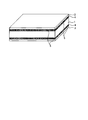
- FIG. 3 schematically shows the coating structure of the magnetic steel sheet according to the present embodiment.
- an intermediate layer 4 based on silicon oxide containing metal phosphide 5 is formed on the surface of a steel plate 1, and an insulating coating 3 is formed thereon.
- the intermediate layer 4 based on silicon oxide may contain ⁇ -iron and / or iron silicate in addition to the metal phosphide 5. The details will be described below.
- the insulating coating is an insulating coating formed by applying and baking a solution mainly composed of a phosphate and colloidal silica (SiO 2 ) on an intermediate layer mainly composed of silicon oxide. This insulating film can impart high surface tension to the steel plate.
- the film thickness of the insulating film is preferably 0.1 ⁇ m or more. More preferably, it is 0.5 ⁇ m or more, 0.8 ⁇ m or more, 1.0 ⁇ m or more, or 2.0 ⁇ m or more.
- the film thickness of the insulating film exceeds 10 ⁇ m, there is a possibility that a crack may occur in the insulating film at the stage of forming the insulating film, so the film thickness of the insulating film is preferably 10 ⁇ m or less. More preferably, it is 5 ⁇ m or less, 4.5 ⁇ m or less, 4.2 ⁇ m or less, or 4.0 ⁇ m or less.
- the insulating film may be subjected to magnetic domain fragmentation treatment to apply local micro strain by laser, plasma, mechanical method, etching, or other methods as necessary.
- the intermediate layer according to the present embodiment contains Si and O, and further contains a metal phosphide.
- the intermediate layer according to the present embodiment may further contain an impurity.
- Such an intermediate layer is referred to as an intermediate layer based on silicon oxide in the present embodiment.
- the intermediate layer mainly composed of silicon oxide has a function of bringing the steel sheet and the insulating coating into close contact, but on the entire surface of the steel sheet, the intermediate layer mainly composed of silicon oxide It has not conventionally been easy to form a strong contact by means of no uniform adhesion.
- the intermediate layer is not an intermediate layer of silicon oxide alone but an intermediate layer in which silicon oxide and a crystalline substance are complexed, the intermediate layer and the steel plate are present in the presence of a crystalline substance.
- it is thought that it adheres firmly with uniform adhesion power without spots, and forms an intermediate layer based on silicon oxide containing various crystalline substances on the steel sheet surface, and the intermediate layer and the steel sheet The adhesion was tested.
- the intermediate layer mainly composed of silicon oxide containing a metal phosphide firmly adheres to the entire surface of the steel sheet.
- the reason is considered to be that the flexibility of the intermediate layer is improved by the irregular shape of the metal phosphide present in the intermediate layer mainly composed of silicon oxide.
- a forsterite film 2 mainly composed of Mg 2 SiO 4 (forsterite) is formed on a steel sheet 1, and the forsterite film 2 and the steel sheet 1
- the interface of is in the form of uneven irregularities (see FIG. 1).
- the uneven shape of the interface which is evaluated by the surface roughness, greatly contributes to the adhesion between the steel plate and the insulating film, and it is said that it is necessary to improve the surface roughness to improve the surface roughness.
- the improvement in the flexibility of the intermediate layer mainly made of silicon oxide is considered to greatly affect the improvement in the adhesion to the surface of the steel sheet.
- the surface roughness is not particularly limited to a particular range. From the viewpoint of improving adhesion, which is the subject of the invention, it is preferable that the surface roughness is large, but it is 0.5 ⁇ m in arithmetic average roughness (Ra) in that a large tension is applied to the steel plate to reduce core loss. The following are preferable and 0.3 micrometer or less are more preferable.
- the intermediate layer according to the present embodiment can ensure the adhesion of the insulating coating.
- the thickness of the steel plate is also not particularly limited to a specific range, but in order to further reduce iron loss, the thickness is preferably 0.35 mm or less, more preferably 0.30 mm or less.
- This embodiment has dense material characteristics such as high strength to endure thermal stress, relatively small elastic modulus, and easy relaxation of thermal stress if oxidation annealing is performed at ordinary temperature (1150 ° C. or lower).
- An intermediate layer according to the present invention can be formed on the surface of a steel plate.
- the steel plate contains high concentration of Si (for example, 0.80 to 4.00 mass%), strong chemical affinity is expressed between the steel plate and the intermediate layer according to the present embodiment, and the steel plate according to the present embodiment The intermediate layer and the steel plate firmly adhere.
- the thickness of the intermediate layer according to the present embodiment is 4 nm or more. Preferably, they are 5 nm or more, 10 nm or more, 20 nm or more, or 50 nm or more.
- the upper limit of the intermediate layer according to the present embodiment is not limited as long as the layer thickness is uniform and there is no defect such as a void or a crack, but if the layer thickness is too thick, the layer thickness becomes uneven.
- the layer thickness of the intermediate layer according to the present embodiment is preferably less than 400 nm, because defects such as voids and cracks may occur. More preferably, it is 300 nm or less, 250 nm or less, 200 nm or less, or 100 nm or less.
- the metal phosphide contained in the intermediate layer according to the present embodiment is preferably Fe 3 P, Fe 2 P, and one or more Fe phosphide of FeP. Since Fe is a constituent element of the steel plate, among metal phosphides, Fe 3 P, Fe 2 P, and FeP greatly contribute to the improvement of the adhesion between the intermediate layer and the steel plate according to the present embodiment. it is conceivable that.
- the abundance of the metal phosphide present in the intermediate layer according to the present embodiment is the ratio of the total cross sectional area of the metal phosphide to the cross sectional area of the entire intermediate layer including the metal phosphide (hereinafter referred to as “cross sectional area ratio” Is displayed.
- the metal phosphide When the cross-sectional area rate of the metal phosphide is small (the amount is small), the metal phosphide does not contribute to the improvement of the flexibility of the intermediate layer, and the required adhesion to the steel plate can not be obtained. 1% or more is preferable. More preferably, it is 2% or more, 5% or more, 10% or more, or 15% or more.
- the above-mentioned cross-sectional area ratio is preferably 30% or less . More preferably, it is 27% or less, 25% or less, 20% or less, or 18% or less.
- the intermediate layer according to the present embodiment may contain ⁇ -iron and / or iron silicate in addition to the metal phosphide.
- Alpha iron is a ferrite phase iron and is a main constituent element of a steel plate.
- Iron silicate is a crystalline Fe 2 SiO 4 (firelite) that is formed when the steel sheet is oxidized and annealed, and may contain a small amount of FeSiO 3 (ferrosilite).
- the thermal sensitivity of the intermediate layer approaches the thermal sensitivity of the steel sheet by the presence of alpha iron of the main constituent element of the steel sheet and / or iron silicate which is chemically compatible with the steel sheet in the silicon oxide-based intermediate layer. It is considered that the flexibility of the intermediate layer is improved, and the adhesion between the intermediate layer and the steel plate is improved. However, even if the intermediate layer contains ⁇ -iron and / or iron silicate, the amount of metal phosphide must be 1 to 30% in the cross-sectional area ratio as described above in the intermediate layer.
- the amount of "metal phosphide and alpha iron and / or iron silicate" present in the middle layer according to the present embodiment is the middle layer including "metal phosphide and &agr; iron and / or iron silicate"
- the ratio of the total cross-sectional area of “metal phosphide and ⁇ -iron and / or iron silicate” to the total cross-sectional area (total cross-sectional area ratio) is indicated.
- the amount of metal phosphide present in the intermediate layer should be 1 to 30% in cross-sectional area as described above.
- alpha iron and / or iron silicate is not an essential component of the intermediate layer according to the present embodiment. Therefore, the total cross-sectional area ratio of “metal phosphide and ⁇ -iron and / or iron silicate” is 1% or more. More preferably, the total cross-sectional area ratio of the metal phosphide and ⁇ -iron and / or iron silicate is 2% or more, 5% or more, 10% or more, or 15% or more.
- the total cross-sectional area rate is preferably 30% or less. More preferably, it is 27% or less, 25% or less, 20% or less, or 18% or less.
- the particle diameter is preferably 1 nm or more. More preferably, it is 3 nm or more.
- metal phosphide and / or alpha iron and / or iron silicate when the particle size of "metal phosphide and / or alpha iron and / or iron silicate" is large, "metal phosphide and / or alpha iron and / or iron silicate” can be a starting point of failure due to stress concentration.
- the above-mentioned particle diameter is preferably 2/3 or less of the thickness of the silicon oxide-based intermediate layer containing "metal phosphide and alpha iron and / or iron silicate". More preferably, it is 1/2 or less of the layer thickness of the intermediate layer.
- the feature of the magnetic steel sheet according to the present embodiment is a silicon phosphide-based intermediate layer containing metal phosphide and, optionally, alpha iron and / or iron silicate and is not directly related to the component composition of the product steel sheet.
- the component composition of the magnetic steel sheet according to the present embodiment is not particularly limited, the directional magnetic steel sheet is manufactured through various processes, and therefore, a preferable raw steel piece (slab) and a slab for manufacturing the magnetic steel sheet according to the present embodiment
- the component composition of the steel plate 1 (base steel plate) will be described.
- % related to the component composition means mass%.
- the base material steel plate of the magnetic steel sheet according to the present embodiment contains, for example, Si: 0.8 to 7.0%, C: 0.005% or less, N: 0.005% or less , S + Se: 0.005% or less, and acid-soluble Al: 0.005% or less, with the balance being Fe and impurities.
- Si 0.8 to 7.0% Si (silicon) increases the electrical resistance of the grain-oriented electrical steel sheet and reduces iron loss.
- the Si content is preferably 0.8% or more, or 2.0% or more.
- the Si content exceeds 7.0%, the saturation magnetic flux density of the base steel plate decreases, and it becomes difficult to miniaturize the iron core by using it with a high magnetic flux density.
- the Si content is preferably 7.0% or less.
- C 0.005% or less C (carbon) forms a compound in a base steel plate and degrades iron loss, so the smaller the better.
- the C content is preferably limited to 0.005% or less.
- the C content is more preferably 0.004% or less, or 0.003% or less.
- the lower limit includes 0% because C is preferably as small as possible, but reducing C to less than 0.0001% significantly increases the manufacturing cost, so 0.0001% is a practical lower limit in terms of manufacture .
- N 0.005% or less N (nitrogen) forms a compound in a base steel plate and degrades iron loss, so the smaller the better.
- the N content is preferably limited to 0.005% or less.
- the upper limit of the N content is preferably 0.004%, more preferably 0.003%. The smaller the N, the better, so the lower limit may be 0%.
- each S (sulfur) and Se (selenium) form a compound in the base steel plate and degrade iron loss, so the smaller the better.
- the content of each of S and Se is preferably 0.005% or less, and the total of both S and Se is preferably limited to 0.005% or less.
- the content of each of S and Se is more preferably 0.004% or less, or 0.003% or less. The lower the content, the lower the content of each of S and Se may be 0%.
- Acid-soluble Al 0.005% or less Acid-soluble Al (acid-soluble aluminum) forms a compound in a base steel plate and degrades iron loss, so the smaller the better.
- the acid soluble Al is preferably 0.005% or less.
- the acid-soluble Al is more preferably 0.004% or less, or 0.003% or less. The lower the acid-soluble Al, the more preferable, so the lower limit may be 0%.
- the balance of the component composition of the above-described base steel plate is composed of Fe and impurities.
- impurity refers to what is mixed from ore as a raw material, scrap, or manufacturing environment, etc. when industrially manufacturing steel.
- the base steel plate of the magnetic steel plate according to the present embodiment may be, for example, Mn (manganese), Bi (bismuth), or B as a selective element instead of a part of Fe which is the above-mentioned remaining portion.
- Boron Ti (titanium), Nb (niobium), V (vanadium), Sn (tin), Sb (antimony), Cr (chromium), Cu (copper), P (phosphorus), Ni (nickel), Mo It may contain at least one selected from (molybdenum).
- the content of the selective element described above may be, for example, as follows.
- the lower limit of the selection element is not particularly limited, and the lower limit may be 0%.
- the effects of the electrical steel sheet according to the present embodiment are not impaired.
- Mn 0% or more and 0.15% or less
- Bi 0% or more and 0.010% or less
- B 0% or more and 0.080% or less
- Ti 0% or more and 0.015% or less
- Nb 0% or more and 0.20% or less
- V 0% or more and 0.15% or less
- Sn 0% or more and 0.30% or less
- Sb 0% or more and 0.30% or less
- Cr 0% or more and 0.30% or less
- Cu 0% or more and 0.40% or less
- P 0% or more and 0.50% or less
- Ni 0% or more and 1.00% or less
- Mo 0% or more and 0.10% or less.
- the preferable component composition C of the raw steel piece (slab) is an element effective in controlling the primary recrystallization texture, it is preferable to set its content to 0.005% or more.
- the C content is more preferably 0.02%, more preferably 0.04%, still more preferably 0.05% or more. If C exceeds 0.085%, decarburization does not proceed sufficiently in the decarburization step, and the required magnetic properties can not be obtained, so C is preferably 0.085% or less. More preferably, it is 0.065% or less.
- Si is preferably 0.80% or more.
- Si is preferably 4.00% or less. More preferably, it is 3.80% or less.
- Mn is less than 0.03%
- 0.03% or more of Mn is preferable. More preferably, it is 0.06% or more.
- Mn is preferably 0.15% or less. More preferably, it is 0.13% or less.
- the amount of acid-soluble Al is less than 0.010%, the amount of precipitation of AlN that functions as an inhibitor is insufficient, and secondary recrystallization does not proceed stably and sufficiently, so 0.010% or more of acid-soluble Al is preferable . More preferably, it is 0.015% or more.
- the acid-soluble Al is preferably 0.065% or less. More preferably, it is 0.060% or less.
- N is less than 0.004%, the precipitation amount of AlN functioning as an inhibitor will be insufficient, and secondary recrystallization will not stably proceed sufficiently, so N is preferably 0.004% or more. More preferably, it is 0.006% or more.
- N is preferably 0.015% or less. More preferably, it is 0.013% or less.
- the sum of one or both of S and Se is less than 0.005%, the precipitation amount of MnS and / or MnSe functioning as an inhibitor is insufficient, and secondary recrystallization does not proceed sufficiently stably.
- the sum of one or both of Se and Se is preferably 0.005% or more. More preferably, it is 0.007% or more.
- the sum of one or both of S and Se is preferably 0.050% or less. More preferably, it is 0.045% or less.
- the balance of the above-mentioned chemical components is Fe and impurities.
- Impurities are raw materials such as ores or scraps when manufacturing steel products industrially, or components that are mixed in due to various factors of the manufacturing process, and are acceptable within a range that does not adversely affect the present invention I mean one.
- the material steel piece contains one or more kinds of other elements such as P, Cu, Ni, Sn, and Sb within a range not to impair the characteristics of the magnetic steel sheet according to the present embodiment. It is also good.
- P is an element that enhances the resistivity of the base steel plate and contributes to the reduction of iron loss, but if it exceeds 0.50%, the hardness increases too much and the rollability decreases, so 0.50%. % Or less is preferable. More preferably, it is 0.35% or less.
- Cu is an element that forms fine CuS or CuSe that functions as an inhibitor and contributes to the improvement of the magnetic properties, but if it exceeds 0.40%, the effect of improving the magnetic properties saturates and the surface during hot rolling 0.40% or less is preferable because it causes wrinkles. More preferably, it is 0.35% or less.
- Ni is an element that enhances the electrical resistivity of the base steel plate and contributes to the reduction of iron loss, but if it exceeds 1.00%, secondary recrystallization becomes unstable, so Ni is 1.00. % Or less is preferable. More preferably, it is 0.75% or less.
- Sn and Sb are elements that segregate to grain boundaries and function to adjust the degree of oxidation during decarburizing annealing, but if over 0.30%, decarburization becomes difficult to progress during decarburizing annealing Therefore, as for both Sn and Sb, 0.30% or less is preferable. More preferably, each element is at most 0.25%.
- the above-described steel billet may additionally contain one or more of Cr, Mo, V, Bi, Nb, and Ti as an element forming an inhibitor.
- the lower limit of these elements is not particularly limited, and may be 0%.
- the upper limit of these elements may be 0.30%, 0.10%, 0.15%, 0.010%, 0.20%, or 0.0150%, respectively.
- a test piece is cut out of the grain-oriented electrical steel sheet on which the insulating film is formed, and the film structure of the test piece is observed with a scanning electron microscope (SEM) or a transmission electron microscope (TEM).
- SEM scanning electron microscope
- TEM transmission electron microscope
- a test piece is cut out so that the cutting direction is parallel to the plate thickness direction (specifically, the test piece is aligned so that the cut surface is parallel to the plate thickness direction and perpendicular to the rolling direction)
- the cross-sectional structure of this cut surface is observed with an SEM at a magnification at which each layer enters in the observation field of view.
- SEM reflection electron composition image
- the steel plate can be identified as light color
- the intermediate layer can be identified as dark color
- the insulating coating can be identified as intermediate color.
- the Fe content is less than 80 atomic% excluding measurement noise
- P content is less than measurement noise from measurement noise from the observation result in the COMP image and the result of quantitative analysis of SEM-EDS 5 atomic% or more
- Si content is less than 20 atomic% excluding measurement noise
- O content is 50 atomic% or more excluding measurement noise
- Mg content is 10 atomic% or less excluding measurement noise If it is an area and the line segment (thickness) on the scanning line of the line analysis corresponding to this area is 300 nm or more, this area is judged to be an insulating film.
- the precipitate, the inclusion, etc. which are contained in an insulating film are not included in judgment object, but the area
- Judge as a film For example, if the presence of precipitates and inclusions on the scanning line of line analysis is confirmed from the results of the COMP image and line analysis, this region is not included in the target, and the insulating coating is Determine if there is. Precipitates and inclusions can be distinguished from the mother phase by contrast in the COMP image, and can be distinguished from the mother phase by the abundance of constituent elements in the quantitative analysis results.
- this area is an intermediate layer to decide.
- the identification of each layer and the measurement of the thickness by the above-mentioned COMP image observation and SEM-EDS quantitative analysis are performed at five or more places while changing the observation field of view.
- the average value is obtained from the value excluding the maximum value and the minimum value, and this average value is used as the average thickness of the intermediate layer and the average thickness of the insulating coating I assume.
- the corresponding layer is observed in detail by TEM. And determine the identity and thickness of the relevant layer by TEM.
- Each layer is specified from the above-mentioned bright field image observation result by TEM and the quantitative analysis result of TEM-EDS, and the thickness of each layer is measured.
- a region where the Fe content is 80 atomic percent or more excluding measurement noise is determined to be a base steel plate, and a region excluding the base steel plate is determined to be an intermediate layer and an insulating film.
- the Fe content is less than 80 atomic% excluding measurement noise
- P content is less than measurement noise from measurement noise from the observation result in the COMP image and the result of quantitative analysis of TEM-EDS 5 atomic% or more
- Si content is less than 20 atomic% excluding measurement noise
- O content is 50 atomic% or more excluding measurement noise
- Mg content is 10 atomic% or less excluding measurement noise Is judged to be an insulating film.
- the region excluding the base steel plate and the insulating coating identified above is determined to be the middle layer.
- a line segment (thickness) is measured on the scanning line of the above line analysis for the intermediate layer and the insulating film specified above.
- the thickness of each layer is 5 nm or less, it is preferable to use a TEM having a spherical aberration correction function from the viewpoint of spatial resolution.
- point analysis is performed at intervals of 2 nm along the thickness direction, line segments (thicknesses) of each layer are measured, and this line segment is adopted as the thickness of each layer.
- the observation and measurement with the above-mentioned TEM are carried out at five or more places while changing the observation field of view, and for the measurement results obtained at five or more places in total, the average value is obtained from the values excluding the maximum value and the minimum value.
- the average value is adopted as the average thickness of the corresponding layer.
- the contents of Fe, P, Si, O, Mg, etc. contained in the above-described base steel plate, intermediate layer, and insulating film are based on the judgment criteria for specifying the base steel plate, intermediate layer, and insulating film. is there.
- the chemical components of the base steel plate, the intermediate layer, and the insulating coating of the electromagnetic steel plate according to the present embodiment are not particularly limited.
- a test piece including the intermediate layer is cut out so that the cutting direction is parallel to the thickness direction (specifically, the cut surface is parallel to the thickness direction and perpendicular to the rolling direction)
- the test piece is cut out), and the cross-sectional structure of this cut surface is observed by TEM at a magnification at which the intermediate layer enters in the observation field of view.
- the precipitate phase present in the intermediate layer is identified by an optional total of five or more bright field images, and the crystalline phase is identified from the analysis of the crystal structure by electron diffraction for this precipitate phase,
- the component elements are confirmed by point analysis by TEM-EDS.
- electron diffraction is performed by narrowing the electron beam so that information from only the target precipitate phase can be obtained from the target precipitate phase described above, and target from the electron beam diffraction pattern Identify the crystal structure of the crystalline phase. This identification may be performed using a PDF (Powder Diffraction File) of ICDD (International Center for Diffraction Data).
- identification may be performed as ⁇ 5% of tolerance of interplanar spacing and ⁇ 3 ° of interplanar angle.
- identification may be performed as ⁇ 5% of tolerance of interplanar spacing and ⁇ 3 ° of interplanar angle.
- the P content of the target crystalline phase is 30 atomic% or more, and the total amount of the P content and the metal element amount is 70 atomic% or more, This crystalline phase can be identified as a metal phosphide.
- the P content of the target crystalline phase is less than 30 atomic% and the Fe content is 70 atomic% or more, this crystalline phase can be confirmed as ⁇ -iron.
- the P content of the target crystalline phase is less than 30 atomic%, the Fe content is 10 atomic% or more, and the Si content is 5 atomic% or more, this crystalline phase is iron silicate It can be confirmed. A total of 25 or more crystalline phases are identified and confirmed at least 5 or more at each location.
- the area fraction of the metal phosphide is determined by image analysis on the basis of the intermediate layer specified above and the metal phosphide specified above. Specifically, the metal phosphorus is obtained from the total cross-sectional area of the intermediate layer present in the region irradiated with the electron beam in a total of five or more observation fields and the total cross-sectional area of the metal phosphide present in the intermediate layer. Determine the area fraction of the oxide. For example, the value obtained by dividing the above-mentioned total cross-sectional area of the metal phosphide by the above-mentioned total cross-sectional area of the intermediate layer is adopted as the average area fraction of the metal phosphide.
- the image is binarized by manually coloring the intermediate layer and the metal phosphide with respect to the tissue photograph based on the above-described identification result of the metal phosphide for the image binarization for image analysis. May be
- the equivalent circle diameter of the metal phosphide is determined by image analysis.
- the circle equivalent diameter of at least 5 or more metal phosphides is determined in each of a total of 5 or more observation fields, the maximum value and the minimum value are removed from the determined circle equivalent diameters, and the average value is calculated Adopted as the equivalent circle equivalent diameter of phosphide.
- the image may be binarized by manually coloring the metal phosphide with respect to the tissue photograph based on the above-described identification result of metal phosphide for the image binarization for image analysis. .
- the surface roughness of a steel plate can be measured using a stylus type surface roughness diameter based on JIS B 0633: 2001.
- the material steel plate may be taken as a measurement target.
- the above-described measurement may be performed after the insulating film is appropriately removed by a known method.
- middle layer is small, it is thought that it does not affect the surface roughness measurement result of a steel plate. Thus, removal of the middle layer is not essential.
- Film adhesion of the insulating film is evaluated by conducting a bending adhesion test. After winding a 80 mm x 80 mm flat test piece around a 20 mm diameter round bar, the oriented electromagnetic steel sheet is stretched flatly, and the area of the insulating film not peeled off from the electromagnetic steel sheet is measured and not peeled off.
- the film adhesion of the insulating film is evaluated by defining the value obtained by dividing the area by the area of the steel plate as the film remaining area ratio (%). For example, it may be calculated by placing a transparent film with a 1-mm scale on a test piece and measuring the area of the insulating film not peeled off.
- the method of manufacturing a grain-oriented electrical steel sheet according to the present embodiment described below can produce the grain-oriented electrical steel sheet according to the present embodiment described above.
- the grain-oriented electrical steel sheet obtained by the manufacturing method that is not the method of manufacturing the magnetic steel sheet according to the present embodiment satisfies the above requirements, there is no unevenness and excellent insulation on the entire surface.
- An intermediate layer based on silicon oxide that is, an intermediate layer containing Si and O
- the directionality electromagnetic steel sheet which fulfills the above-mentioned requirements is a directionality electromagnetic steel sheet concerning this embodiment irrespective of the manufacturing method.
- a steel strip is hot-rolled to obtain a hot-rolled steel sheet.
- a step of annealing the hot-rolled steel plate if necessary, a step of cold-rolling the hot-rolled steel plate to obtain a cold-rolled steel plate, decarburizing the cold-rolled steel plate, the surface of the cold-rolled steel plate
- a step of forming an oxide layer a step of applying an annealing separator on the surface of a cold rolled steel sheet having an oxide layer, a step of winding the cold rolled steel sheet after drying the annealing separator, and a wound cold
- a step of finish annealing the rolled steel plate a step of applying the first solution, and a step of further annealing the cold rolled steel plate coated with the first solution to form an intermediate layer containing metal phosphide (thermal oxidation Annealing), applying a
- the first solution contains phosphoric acid and a metal compound, and the mass ratio of phosphoric acid to the metal compound is 2: 1 to 1: 2, and annealing to form an intermediate layer.
- the annealing temperature is 600 to 1150 ° C.
- the annealing time is 10 to 600 seconds
- the dew point in the annealing atmosphere is ⁇ 20 to 2 ° C.
- the ratio of the amount of hydrogen and the amount of nitrogen in the annealing atmosphere is 75%: 25%. It is characterized in that the application amount of the first solution is controlled such that the amount of the metal phosphide is 1 to 30% in the cross sectional area ratio in the cross section of the intermediate layer.
- the method of manufacturing a grain-oriented electrical steel sheet may include the step of removing the inorganic mineral substance film generated by finish annealing before applying the first solution, wherein the annealing separator is mainly composed of magnesia It may be one.
- (a) on the surface of a grain-oriented electrical steel sheet from which a film of an inorganic mineral substance such as forsterite formed on the surface of the steel sheet has been removed by finish annealing by means such as pickling or grinding
- the directional electromagnetic steel sheet in which the coating of an inorganic mineral substance such as forsterite is removed by pickling, grinding or the like, and the directional electromagnetic steel sheet in which the formation of the oxide layer of the inorganic mineral substance is suppressed is as follows. To make.
- a silicon steel piece containing 2.0 to 4.0 mass% of Si is hot-rolled to form a hot-rolled steel sheet, and if necessary, the hot-rolled steel sheet is annealed and then a hot-rolled steel sheet or an annealed hot-rolled steel sheet , Apply one cold rolling, or two or more cold rolling sandwiching intermediate annealing to finish the steel plate of final thickness, and then carry out decarburizing annealing on the steel plate and advance primary recrystallization .
- An oxide layer is formed on the surface of the steel sheet by decarburization annealing.
- annealing so-called hot-rolled sheet annealing
- annealing is not essential, it may be carried out to improve product characteristics.
- an annealing separator containing magnesia as a main component is coated on the surface of a steel plate having an oxide layer, dried, dried, wound into a coil, and subjected to finish annealing (secondary recrystallization).
- finish annealing a forsterite film mainly composed of forsterite (Mg 2 SiO 4 ) is formed on the surface of the steel plate, and the film is removed by means of acid washing, grinding or the like.
- the steel sheet surface is finished smooth by chemical polishing or electropolishing. It is preferable to set the surface roughness of the steel plate to 0.5 ⁇ m or less in arithmetic average roughness Ra by chemical polishing or electropolishing because the core loss characteristics of the grain-oriented electrical steel plate are significantly improved.
- an annealing separator composed mainly of alumina can be used as an annealing separator, which is coated, dried, dried, wound into a coil, and finish-annealed (secondary recrystallization) To serve.
- finish annealing it is possible to produce a grain-oriented electrical steel sheet while suppressing the formation of an inorganic mineral substance film such as forsterite.
- the steel sheet surface is finished smooth by chemical polishing or electric field polishing.
- Phosphoric acid and phosphoric acid react with phosphoric acid and phosphoric acid on the surface of a grain-oriented electrical steel sheet from which a film of an inorganic mineral substance such as forsterite has been removed or on the surface of a grain-oriented electrical steel sheet which suppresses the formation of a film of an inorganic mineral substance such as forsterite
- a solution (a first solution) containing a compound containing a metal element that forms a metal phosphide is applied and annealed to form an intermediate layer according to the present embodiment.
- Sources of metal phosphide metal are, for example, chlorides, sulfates, carbonates, nitrates, phosphates, simple metals, etc.
- Fe 3 P, Fe 2 P, and FeP are preferably used alone or in combination of two or more in view of securing such adhesion. Therefore, the compound containing a metal element which reacts with phosphoric acid to form a metal phosphide is preferably a compound containing Fe. In view of the reactivity with phosphoric acid, FeCl 3 is preferred. When an organic phosphoric acid or phosphate is used as a source of phosphorus in the metal phosphide, the amount of metal phosphide may be insufficient. Therefore, the first solution should contain phosphoric acid.
- the ratio of phosphoric acid in the first solution to be applied to the compound containing a metal element that reacts with phosphoric acid to form a metal phosphide is in a weight ratio of 2: 1 to 1: 2, preferably 1: 1 to 1: Adjust to 1.5.
- the ratio of phosphoric acid to the compound containing a metal element within the above range, the adhesion of the insulating film can be sufficiently improved. If phosphoric acid runs short, no metal phosphide is formed in the intermediate layer.
- the application amount of the first solution is determined according to the thickness of the intended intermediate layer.
- the amount of metal phosphide itself in the intermediate layer is determined by the application amount of phosphoric acid and the compound containing the metal element.
- the thickness of the intermediate layer is determined by the annealing temperature, the annealing time, and the dew point of the annealing atmosphere, as described later. Therefore, the cross-sectional area ratio in the middle layer cross section of the metal phosphide will be determined by both the application amount of the compound and the annealing conditions. For the above reasons, it is necessary to determine the application amount of the first solution in accordance with the intermediate layer thickness. For example, when annealing is performed under the condition that the thickness of the intermediate layer is 4 nm, the coating amount of the first solution may be 0.03 to 4 mg / m 2 .
- the application amount of the first solution may be 3 to 400 mg / m 2 .
- the application amount of the first solution is the application amount of phosphoric acid and a compound containing a metal element, and the mass of water or the like as these solvents is not included in the application amount of the first solution.
- the annealing for forming the intermediate layer according to the present embodiment may be held at the temperature at which the metal phosphide is generated for a required time, and is not particularly limited to a specific temperature and holding time, but phosphoric acid and metal phosphide are produced.
- the annealing temperature is preferably 600 to 1150 ° C. from the viewpoint of promoting the reaction of the compound containing the metal element.
- the annealing temperature is preferably 700 to 1150 ° C.
- the annealing time is preferably 10 to 600 seconds.
- the annealing atmosphere is preferably a reducing atmosphere so that the inside of the steel sheet is not oxidized, and particularly preferably a nitrogen atmosphere in which hydrogen is mixed.
- a nitrogen atmosphere in which hydrogen is mixed.
- an atmosphere having a hydrogen: nitrogen ratio of 75%: 25% and a dew point of ⁇ 20 to 2 ° C. is preferable.
- the atmosphere may be controlled focusing on the oxidation potential.
- the annealing atmosphere is preferably such that the oxygen partial pressure (PH 2 O 2 / PH 2 : the ratio of the water vapor partial pressure and the hydrogen partial pressure) is in the range of 0.0016 to 0.0093.
- the abundance of the metal phosphide in the intermediate layer according to the present embodiment is preferably 1 to 30% in terms of the sectional area ratio in the cross section of the intermediate layer according to the present embodiment. Preferably, it is 5 to 25%.
- the intermediate layer according to the present embodiment may contain ⁇ -iron and / or iron silicate in addition to the metal phosphide.
- Alpha iron is produced by reduction of an iron compound
- iron silicate is produced by the redox reaction of alpha iron or an iron compound and silicon oxide.
- the abundance of these substances is the cross-sectional area ratio in the cross section of the intermediate layer according to the present embodiment And preferably 1 to 30%. Preferably, it is 5 to 25%.
- the layer thickness of the intermediate layer according to the present embodiment is adjusted by adjusting one or more of the annealing temperature, the holding time, and the dew point of the annealing atmosphere.
- the thickness of the intermediate layer according to this embodiment is preferably 4 to 400 nm. More preferably, it is 5 to 300 nm.
- the film thickness of the intermediate layer becomes thicker as the annealing temperature is higher, the holding time is longer, and the dew point of the annealing atmosphere is higher.
- the thickness of the intermediate layer is set to a predetermined value by adjusting one or more of the annealing temperature, the holding time, which is a controlling factor of the film thickness, and the dew point of the annealing atmosphere. Prepare within the range.
- the cooling of the steel sheet after annealing is performed while maintaining the oxidation degree of the annealing atmosphere low so that the metal phosphide does not chemically change.
- the treatment is performed in an atmosphere of hydrogen: nitrogen 75%: 25% and a dew point of ⁇ 50 to ⁇ 20 ° C.
- a sol-gel method may be used as a method of forming the intermediate layer according to the present embodiment.
- a silica gel in which a phosphorus compound is dissolved in a water-alcohol solvent is coated on the surface of a steel plate, dried by heating to 200 ° C. in air, dried and dried at 300 to 1000 ° C. for 1 minute in a reducing atmosphere. Hold and air cool.
- the particle size of the metal phosphide and alpha iron and / or iron silicate which the intermediate layer concerning this embodiment contains 1 nm or more is preferred. More preferably, it is 3 nm or more.
- the particle diameter is preferably 2/3 or less of the layer thickness of the intermediate layer according to the present embodiment. More preferably, it is 1/2 or less of the layer thickness of the intermediate
- the ratio of phosphoric acid in the first solution and the compound containing the metal element which reacts with phosphoric acid to form the metal phosphide is lowered (that is, There was a tendency to increase as the ratio decreased. It is believed that the preferred particle size can be obtained by adjusting one or more of these control factors.
- a second solution mainly composed of a phosphate and colloidal silica is applied on the intermediate layer according to the present embodiment, and baked at 850 ° C., for example, to form a phosphoric acid-based insulating film.
- a well-known method can be used suitably for the control method of the film thickness of insulation coating.
- the thickness of the insulating coating can be controlled by changing the application amount of the second solution mainly containing phosphate and colloidal silica.
- Film adhesion of the insulating film is evaluated by conducting a bending adhesion test. After winding a grain-oriented electrical steel sheet around a round bar with a diameter of 20 mm, unroll it flatly, measure the area of the insulating film not peeled off from the steel sheet, and the ratio of the area to the area of the steel sheet: film remaining area ratio (% ) Is evaluated to evaluate the film adhesion of the insulation film.
- Example of this invention the conditions in an Example are one condition example employ
- the present invention can adopt various conditions as long as the object of the present invention is achieved without departing from the scope of the present invention.
- evaluation of each Example demonstrated below was implemented by the evaluation method mentioned above.
- Example 1 A silicon steel piece having the component composition shown in Table 1 was homogenized at 1150 ° C. for 60 minutes and subjected to hot rolling to obtain a 2.3 mm-thick hot-rolled steel plate. Next, the hot rolled steel sheet is held at 1120 ° C. for 200 seconds, immediately subjected to annealing to hold rapidly at 900 ° C. for 120 seconds, quenched, pickled, subjected to cold rolling, and final thickness 0.23 mm It was a cold rolled steel plate.
- the cold-rolled steel plate (hereinafter referred to as "steel plate") was subjected to decarburization annealing at 850 ° C. for 180 seconds in an atmosphere of 75%: 25% partial pressure of hydrogen and nitrogen.
- the steel sheet after decarburization annealing was subjected to nitriding annealing held at 750 ° C. for 30 seconds in a mixed atmosphere of hydrogen, nitrogen and ammonia to adjust the nitrogen content of the steel sheet to 230 ppm.
- an annealing separator containing alumina as the main component to the steel sheet after nitriding annealing, and then heat it to 1200 ° C at a heating rate of 15 ° C / hour in a mixed atmosphere of hydrogen and nitrogen to finish annealing
- purification annealing was performed under hydrogen atmosphere and maintained at 1200 ° C. for 20 hours, and then naturally cooled to produce a grain-oriented electrical steel sheet having a smooth surface.
- Arithmetic mean roughness Ra of this grain-oriented electrical steel sheet was 0.21 ⁇ m.
- An aqueous solution containing the coating shown in Table 2 is coated on the smooth surface of the produced grain-oriented electrical steel sheet so that the amount of the coating excluding water becomes the coating amount shown in Table 2, hydrogen: nitrogen 75%: 25%, heating to 1000 ° C at a heating rate of 8 ° C / sec in an atmosphere with a dew point of -20 ° C, and after heating, immediately change the dew point of the atmosphere to -5 ° C and hold for 60 seconds did.
- the ratio of phosphoric acid to the compound containing a metal element in all the coated products shown in Table 2 was in the range of 2: 1 to 1: 2 by mass ratio. After holding, the dew point of the atmosphere was immediately changed to -50.degree. C. for natural cooling.
- the dew point of the atmosphere was set low to suppress the oxidation reaction.
- the dew point of the atmosphere was kept low to suppress the chemical change of the metal phosphide in the silicon oxide-based intermediate layer.
- the dew point of the atmosphere was kept high in order to form an intermediate layer mainly composed of silicon oxide.
- an intermediate layer based on silicon oxide containing metal phosphide and alpha iron and / or iron silicate was formed. The layer thickness of the formed intermediate layer is shown together in Table 2.
- An aqueous solution mainly composed of magnesium phosphate, colloidal silica, and chromic anhydride was coated on the surface of the formed intermediate layer, and baked at 850 ° C. for 30 seconds in a nitrogen atmosphere to form an insulating film.
- a test piece was cut out of the grain-oriented electrical steel sheet on which the insulating coating was formed, and the cross section was observed with a transmission electron microscope, and the thickness of the intermediate layer and the total cross-sectional area ratio of the materials contained in the intermediate layer were measured.
- the element ratio of the substance mainly forming the intermediate layer to the substance contained in the intermediate layer was identified by energy dispersive X-ray spectroscopy, and the substance contained in the intermediate layer was identified by electron beam diffraction. The results are shown together in Table 2.
- the substance mainly forming the intermediate layer is silicon oxide.
- Fe 2 P, FeP, ⁇ iron, and Fe 2 SiO 4 were present in the intermediate layer of the test piece A3. It is considered that these materials are formed of Fe of the coated material FeCl 3 , P of the coated material phosphoric acid, and Si and O of silicon oxide mainly of the intermediate layer.
- the particle size (average value of equivalent circle diameter) of the metal phosphide of all the test pieces disclosed in Table 2 was in the range of 1 nm or more and 2/3 or less of the layer thickness of the intermediate layer.
- the film remaining area ratio of the test piece A1 in which the intermediate layer does not contain phosphide, ⁇ iron and Fe 2 SiO 4 is 81%, while the intermediate layer is made of Fe 2 P, FeP, ⁇ iron and The film remaining area ratio of the test piece A3 containing Fe 2 SiO 4 is 97%. From this, it is understood that when the intermediate layer based on silicon oxide contains Fe phosphide, the film adhesion of the insulating film is significantly improved.
- the film remaining area ratio of the test pieces A4 to A6 in which the silicon oxide-based intermediate layer contains Co 2 P, Ni 2 P, or Cu 3 P is 90% or less, and Co 2 P, Ni 2 P, and It is understood that Cu 3 P does not contribute to the improvement of the adhesion of the insulating film as much as Fe 2 P and FeP. However, as compared with the test piece A2, the film adhesion is improved, and the intermediate layer containing Co 2 P, Ni 2 P, and Cu 3 P is also an invention example.
- Example 2 As in Example 1, a grain-oriented electrical steel sheet having a smooth surface was produced. An aqueous solution containing the coating shown in Table 3 is coated on the surface of this grain-oriented electrical steel sheet such that the amount of coating excluding water is the coating amount shown in Table 3, and hydrogen: nitrogen is 75%: It was heated to 1150 ° C. at a heating rate of 8 ° C./s in a 25%, atmosphere with a dew point of ⁇ 20 ° C. The ratio of phosphoric acid to the compound containing a metal element in all the coated products shown in Table 3 was in the range of 2: 1 to 1: 2 by mass ratio.
- the dew point of the atmosphere is immediately changed to -3 ° C, and the holding time shown in Table 3 is maintained, and after holding, the dew point of the atmosphere is immediately changed to -30 ° C to form an intermediate layer on the smooth surface of the steel plate. And allowed to cool naturally after formation.
- Example 3 In the same manner as in Example 1, an insulating film is formed on the above-mentioned intermediate layer, and the substance mainly forming the intermediate layer and the substance contained in the intermediate layer are identified, and the total cross-sectional area ratio of the substances and the insulation The film remaining area ratio of the film was measured. The results are shown in Table 3. In addition, the particle size (average value of equivalent circle diameter) of the metal phosphide of all the test pieces disclosed in Table 3 was in the range of 1 nm or more and 2/3 or less of the layer thickness of the intermediate layer.
- the substance mainly forming the intermediate layer was silicon oxide. While the thickness of the intermediate layer is 583 nm and the film residual area ratio of the test piece A11 is 90% or less, the film residual area ratio of the intermediate layer having a thickness of 400 nm or less is 90% or more It is. Thus, the thickness of the intermediate layer is preferably 400 nm or less. However, because the thickness of the intermediate layer was more than 400 nm, the test piece A11 also had a film remaining area ratio exceeding 85%, which is a pass / fail criterion, and thus it was judged as an invention example.
- Example 3 In the same manner as in Example 1, a grain-oriented electrical steel sheet having a smooth surface was produced. An aqueous solution containing the coating shown in Table 4 is coated on the surface of this grain-oriented electrical steel sheet such that the amount of coating excluding water is the coating amount shown in Table 4, and hydrogen: nitrogen is 75%: It was heated to 700 ° C. at a heating rate of 6 ° C./s in a 25%, atmosphere with a dew point of ⁇ 20 ° C. The ratio of phosphoric acid to the compound containing a metal element in all the coated products shown in Table 4 was in the range of 2: 1 to 1: 2 by mass ratio.
- the dew point of the atmosphere is immediately changed to 1 ° C., and the holding time shown in Table 4 is held, and after holding, the dew point of the atmosphere is immediately changed to -40 ° C., and the intermediate layer is formed on the smooth surface of the steel plate. After formation and formation, it was naturally cooled.
- Example 4 In the same manner as in Example 1, an insulating film is formed on the above-mentioned intermediate layer, a substance mainly constituting the intermediate layer and a substance contained in the intermediate layer are identified, and further, the total cross-sectional area ratio of the substances, The film remaining area ratio of the insulating film was measured. The results are shown in Table 4. In addition, the particle size (average value of equivalent circle diameter) of the metal phosphide of all the test pieces disclosed in Table 4 was in the range of 1 nm or more and 2/3 or less of the layer thickness of the intermediate layer.
- the substance mainly forming the intermediate layer was silicon oxide.
- the materials contained in the intermediate layer were Fe 2 P, Fe 3 P, and / or FeP, and alpha iron and Fe 2 SiO 4 were not detected. This is considered to be because ⁇ -iron and Fe 2 SiO 4 were not generated because the annealing holding temperature for forming the intermediate layer is as low as 700 ° C.
- the film remaining area ratio of the test piece A12 having an intermediate layer thickness of less than 4 nm is less than 90%
- the film remaining area ratio of the test pieces A13 to A15 having an intermediate layer thickness of 8 to 21 nm is 90% It is above.
- the thickness of the intermediate layer is 4 nm or more, a grain-oriented electrical steel sheet having better film adhesion can be obtained.
- the total cross-sectional area ratio of the sample A16 in which the total cross-sectional area ratio of the substances present in the intermediate layer is 0.6% is less than 90%
- the total cross-sectional area ratio of the substances present in the intermediate layer is 1
- the film remaining area ratio became 90% or more.
- Example 4 A silicon steel piece (slab) whose component composition is shown in Table 1 was homogenized at 1150 ° C. for 60 minutes and subjected to hot rolling to obtain a 2.3 mm thick hot rolled steel sheet. Next, the hot rolled steel sheet is held at 1120 ° C. for 200 seconds and immediately annealed at 900 ° C. for 120 seconds for rapid cooling, pickling, cold rolling and final thickness 0.27 mm. Cold rolled steel sheet.
- the cold-rolled steel plate (hereinafter referred to as "steel plate”) was subjected to decarburization annealing held at 850 ° C. for 180 seconds in an atmosphere of hydrogen: nitrogen 75%: 25%.
- the steel sheet after decarburization annealing was subjected to nitriding annealing held at 750 ° C. for 30 seconds in a mixed atmosphere of hydrogen, nitrogen and ammonia to adjust the nitrogen content of the steel sheet to 230 ppm.
- an annealing separator containing magnesia as a main component is applied to the steel sheet after nitriding annealing, and thereafter, it is heated to 1200 ° C. at a temperature rising rate of 15 ° C./hour in a mixed atmosphere of hydrogen and nitrogen to finish annealing. Then, purification annealing was performed by holding at 1200 ° C. for 20 hours in a hydrogen atmosphere, and then the steel plate after purification annealing was naturally cooled.
- Arithmetic mean roughness Ra of this grain-oriented electrical steel sheet was 0.14 ⁇ m.
- aqueous solution containing the coating shown in Table 5 is coated on the surface of this grain-oriented electrical steel sheet such that the amount of coating excluding water is the coating amount shown in Table 5, and hydrogen: nitrogen is 75%: Heat to 800 ° C at a heating rate of 6 ° C / s in an atmosphere with a dew point of -20 ° C at 25%, and after heating, immediately change the dew point of the atmosphere to -1 ° C and hold as shown in Table 5 After holding for a time and holding, the dew point of the atmosphere was immediately changed to -50.degree. C. to form an intermediate layer on the smooth surface, and natural cooling was performed after formation.
- the ratio of phosphoric acid to the compound containing a metal element in all the coated products shown in Table 5 was in the range of 2: 1 to 1: 2 by mass ratio.
- Example 5 In the same manner as in Example 1, an insulating film is formed on the above-mentioned intermediate layer, and the substance mainly forming the intermediate layer and the substance contained in the intermediate layer are identified, and the total cross-sectional area ratio of the substances and the insulation The film remaining area ratio of the film was measured. The results are shown in Table 5. In addition, the particle size (average value of equivalent circle diameter) of the metal phosphide of all the test pieces disclosed in Table 5 was in the range of 1 nm or more and 2/3 or less of the layer thickness of the intermediate layer.
- the substance mainly forming the intermediate layer was silicon oxide. While the film remaining area ratio of the test piece A17 having a total cross sectional area ratio of 63% of the materials contained in the intermediate layer is less than 90%, the test in which the total cross sectional area ratio of the materials contained in the intermediate layer is 30% or less The film remaining area ratio of the pieces A18 to A20 is 90% or more. Thus, it is understood that when the total cross-sectional area ratio of the materials contained in the intermediate layer is 30% or less, a grain-oriented electrical steel sheet excellent in film adhesion can be obtained.
- metal phosphide and, as appropriate, alpha iron and / or iron silicate are contained on the entire surface of the steel sheet, thereby securing the adhesion of the insulating coating with no unevenness and excellent insulating coating. It is possible to provide a grain-oriented electrical steel sheet comprising a silicon oxide-based intermediate layer, and a method of manufacturing the same. Therefore, the present invention is highly applicable in the electromagnetic steel sheet manufacturing and utilization industry.
Landscapes
- Chemical & Material Sciences (AREA)
- Engineering & Computer Science (AREA)
- Materials Engineering (AREA)
- Metallurgy (AREA)
- Organic Chemistry (AREA)
- Mechanical Engineering (AREA)
- Physics & Mathematics (AREA)
- Crystallography & Structural Chemistry (AREA)
- Thermal Sciences (AREA)
- Chemical Kinetics & Catalysis (AREA)
- Electromagnetism (AREA)
- Manufacturing & Machinery (AREA)
- General Chemical & Material Sciences (AREA)
- Power Engineering (AREA)
- Dispersion Chemistry (AREA)
- Inorganic Chemistry (AREA)
- Electrochemistry (AREA)
- Manufacturing Of Steel Electrode Plates (AREA)
- Soft Magnetic Materials (AREA)
- Chemical Treatment Of Metals (AREA)
- Other Surface Treatments For Metallic Materials (AREA)
Abstract
Description
本願は、2017年7月13日に、日本に出願された特願2017-137419号に基づき優先権を主張し、その内容をここに援用する。
(1)本発明の一態様に係る方向性電磁鋼板は、鋼板と、前記鋼板の上に配されたSi及びOを含む中間層と、前記中間層の上に配された絶縁被膜とを有する方向性電磁鋼板であって、前記中間層が金属燐化物を含有し、前記中間層の層厚が4nm以上であり、前記金属燐化物の存在量が、前記中間層の断面における断面面積率で1~30%である。
(2)上記(1)に記載の方向性電磁鋼板では、前記金属燐化物が、Fe3P、Fe2P、及び、FePの1種又は2種以上のFe燐化物であってもよい。
(3)上記(1)又は(2)に記載の方向性電磁鋼板では、前記中間層が、前記金属燐化物に加えてα鉄及び/又は珪酸鉄を含有してもよい。
(4)上記(1)~(3)のいずれか1項に記載の方向性電磁鋼板では、前記金属燐化物、及び、α鉄及び/又は珪酸鉄の合計の存在量が、前記中間層の断面における断面面積率で1~30%であってもよい。
(5)上記(1)~(4)のいずれか1項に記載の方向性電磁鋼板では、前記中間層の層厚が400nm未満であってもよい。
(6)上記(1)~(5)のいずれか1項に記載の方向性電磁鋼板では、前記絶縁被膜の膜厚が0.1~10μmであってもよい。
(7)上記(1)~(6)のいずれか1項に記載の方向性電磁鋼板では、前記鋼板の表面粗度が、算術平均粗さRaで0.5μm以下であってもよい。
(8)本発明の別の態様に係る方向性電磁鋼板の製造方法は、上記(1)~(7)のいずれか1項に記載の方向性電磁鋼板の製造方法であって、鋼片を熱間圧延して熱延鋼板を得る工程と、前記熱延鋼板を冷間圧延して冷延鋼板を得る工程と、前記冷延鋼板を脱炭焼鈍して、前記冷延鋼板の表面に酸化層を形成する工程と、前記酸化層を有する前記冷延鋼板の表面に焼鈍分離剤を塗布する工程と、前記焼鈍分離剤を乾燥させてから、前記冷延鋼板を巻き取る工程と、巻き取られた前記冷延鋼板を仕上げ焼鈍する工程と、第一の溶液を塗布する工程と、前記第一の溶液が塗布された前記冷延鋼板をさらに焼鈍して、金属燐化物を含む中間層を形成する工程と、前記中間層の表面に第二の溶液を塗布する工程と、前記第二の溶液が塗布された前記冷延鋼板に焼き付けをする工程と、を備え、前記第一の溶液が、燐酸と金属化合物とを含み、前記燐酸と前記金属化合物との質量比が2:1~1:2であり、前記中間層を形成するための焼鈍において、焼鈍温度を600~1150℃とし、焼鈍時間を10~600秒とし、焼鈍雰囲気における露点を-20~2℃とし、前記焼鈍雰囲気における水素量及び窒素量の比率を75%:25%とし、前記金属燐化物の存在量が、前記中間層の断面における断面面積率で1~30%となるように前記第一の溶液の塗布量を制御する。
(9)上記(8)に記載の方向性電磁鋼板の製造方法は、さらに、前記第一の溶液を塗布する前に、前記仕上げ焼鈍によって生じた無機鉱物質被膜を除去する工程を備えてもよく、前記焼鈍分離剤がマグネシアを主成分としてもよい。
(10)上記(8)又は(9)に記載の方向性電磁鋼板の製造方法は、さらに、前記冷間圧延の前に、前記熱延鋼板を焼鈍する工程を備えてもよい。
絶縁被膜は、酸化珪素主体の中間層の上に、燐酸塩とコロイド状シリカ(SiO2)を主体とする溶液を塗布して焼き付けて形成する絶縁被膜である。この絶縁被膜は、鋼板に高い面張力を付与することができる。
本実施形態に係る中間層は、Si及びOを含み、さらに金属燐化物を含む。本実施形態に係る中間層は、さらに不純物を含んでもよい。このような中間層を、本実施形態では、酸化珪素主体の中間層と称する。上記三層構造の被膜構造(図2、参照)において、酸化珪素主体の中間層は、鋼板と絶縁被膜を密着させる機能を有するが、鋼板の全面に、酸化珪素主体の中間層を、斑のない均一な密着力で強固に密着させて形成することは、従来から容易でなかった。
本実施形態に係る電磁鋼板の母材鋼板は、例えば、Si:0.8~7.0%を含有し、C:0.005%以下、N:0.005%以下、S+Se:0.005%以下、かつ酸可溶性Al:0.005%以下に制限し、残部がFe及び不純物からなる。
Si(シリコン)は、方向性電磁鋼板の電気抵抗を高めて鉄損を低下させる。Si含有量は好ましくは0.8%以上、又は2.0%以上である。一方、Si含有量が7.0%を超えると、母材鋼板の飽和磁束密度が低下してしまい、高い磁束密度で使用して鉄心を小型化することが難くなってしまう。以上の理由により、Si含有量は7.0%以下とすることが好ましい。
C(炭素)は、母材鋼板中で化合物を形成し、鉄損を劣化させるため、少ないほど好ましい。C含有量は、0.005%以下に制限することが好ましい。C含有量は、さらに好ましくは0.004%以下、又は0.003%以下である。Cは、少ないほど好ましいので、下限は0%を含むが、Cを0.0001%未満に低減すると、製造コストが大幅に上昇するので、製造上、0.0001%が実質的な下限である。
N(窒素)は、母材鋼板中で化合物を形成し、鉄損を劣化させるため、少ないほど好ましい。N含有量は、0.005%以下に制限することが好ましい。N含有量の好ましい上限は0.004%であり、さらに好ましくは0.003%である。Nは、少ないほど好ましいので、下限が0%であればよい。
S(硫黄)及びSe(セレン)は、母材鋼板中で化合物を形成し、鉄損を劣化させるため、少ないほど好ましい。S及びSeそれぞれの含有量を0.005%以下にすることが好ましく、さらに、S及びSeの両方の合計も0.005%以下に制限することが好ましい。S及びSeそれぞれの含有量は、さらに好ましくは0.004%以下、又は0.003%以下である。少ないほど好ましいので、S及びSeそれぞれの含有量の下限は、それぞれ0%であればよい。
酸可溶性Al(酸可溶性アルミニウム)は、母材鋼板中で化合物を形成し、鉄損を劣化させるため、少ないほど好ましい。酸可溶性Alは0.005%以下であることが好ましい。酸可溶性Alはさらに好ましくは0.004%以下、又は0.003%以下である。酸可溶性Alは少ないほど好ましいので、下限が0%であればよい。
Mn:0%以上かつ0.15%以下、
Bi:0%以上かつ0.010%以下、
B:0%以上かつ0.080%以下、
Ti:0%以上かつ0.015%以下、
Nb:0%以上かつ0.20%以下、
V:0%以上かつ0.15%以下、
Sn:0%以上かつ0.30%以下、
Sb:0%以上かつ0.30%以下、
Cr:0%以上かつ0.30%以下、
Cu:0%以上かつ0.40%以下、
P:0%以上かつ0.50%以下、
Ni:0%以上かつ1.00%以下、及び
Mo:0%以上かつ0.10%以下。
Cは一次再結晶集合組織を制御するうえで有効な元素であるので、その含有量を0.005%以上とすることが好ましい。C含有量は、より好ましくは0.02%、より好ましくは0.04%、更に好ましくは0.05%以上である。Cが0.085%を超えると、脱炭工程で脱炭が十分に進行せず、所要の磁気特性が得られないので、Cは0.085%以下が好ましい。より好ましくは0.065%以下である。
具体的には、上記の対象とする析出物相に対して、対象の析出物相のみからの情報が得られるように電子線を絞って電子線回折を行い、電子線回折パターンから対象とする結晶質相の結晶構造を同定する。この同定は、ICDD(International Centre for Diffraction Data)のPDF(Powder Diffraction File)を用いて行えばよい。電子線回折結果から、基本的に結晶質相が、Fe3P、Fe2P、FeP、FeP2、およびFe、Fe2SiO4であるか否かを判断できる。
なお、結晶質相がFe3Pであるかの同定は、PDF:No.01-089-2712に基づいて行えばよい。結晶質相がFe2Pであるかの同定は、PDF:No.01-078-6749に基づいて行えばよい。結晶質相がFePであるかの同定は、PDF:No.03-065-2595に基づいて行えばよい。結晶質相がFeP2であるかの同定は、PDF:No.01-089-2261に基づいて行えばよい。結晶質相を上記のPDFに基づいて同定する場合、面間隔の許容誤差±5%および面間角度の許容誤差±3°として同定を行えばよい。
また、TEM-EDSによる点分析の結果、対象とする結晶質相のP含有量が30原子%以上であり、且つP含有量と金属元素量との合計量が70原子%以上であれば、この結晶質相を金属燐化物であると確認できる。また、対象とする結晶質相のP含有量が30原子%未満であり、Fe含有量が70原子%以上であれば、この結晶質相をα鉄であると確認できる。対象とする結晶質相のP含有量が30原子%未満であり、Fe含有量が10原子%以上であり、Si含有量が5原子%以上であれば、この結晶質相を珪酸鉄であると確認できる。
各箇所で少なくとも5個以上、計25個以上の結晶質相の同定・確認を行う。
第一の溶液の塗布量は、目的とする中間層の厚さに応じて決定する。中間層における金属燐化物の量自体は、燐酸と、金属元素を含む化合物との塗布量によって決まる。一方、中間層の厚さは、後述するように、焼鈍温度、焼鈍時間、また焼鈍雰囲気の露点によって決まる。従って、化合物の塗布量及び焼鈍条件の両方によって、金属燐化物の中間層断面における断面面積率が決まることとなる。以上の理由から、第一の溶液の塗布量を中間層厚さに応じて決定する必要がある。例えば、中間層の厚みが4nmとなる条件で焼鈍をする場合は、第一の溶液の塗布量を0.03~4mg/m2とすればよい。中間層の厚みが400nm弱となる条件で焼鈍をする場合は、第一の溶液の塗布量を3~400mg/m2とすればよい。なお、第一の溶液の塗布量とは、燐酸と、金属元素を含む化合物との塗布量であり、これらの溶媒である水などの質量は第一の溶液の塗布量に含まれない。
表1に示す成分組成の珪素鋼片を1150℃で60分均熱して熱間圧延に供し、2.3mm厚の熱延鋼板とした。次いで、この熱延鋼板に、1120℃で200秒保持した後、直ちに、900℃に120秒保持して急冷する焼鈍を施し、酸洗後、冷間圧延に供し、最終板厚0.23mmの冷延鋼板とした。


実施例1と同様に、平滑表面を有する方向性電磁鋼板を作製した。この方向性電磁鋼板の表面に、表3に示す塗布物を含む水溶液を、水を除いた塗布物の量が、表3に示す塗布量となるように塗布し、水素:窒素が75%:25%で、露点が-20℃の雰囲気で、8℃/秒の昇温速度で1150℃まで加熱した。なお、表3に示す全ての塗布物における燐酸と金属元素を含む化合物との比率は、質量比で2:1~1:2の範囲内とした。
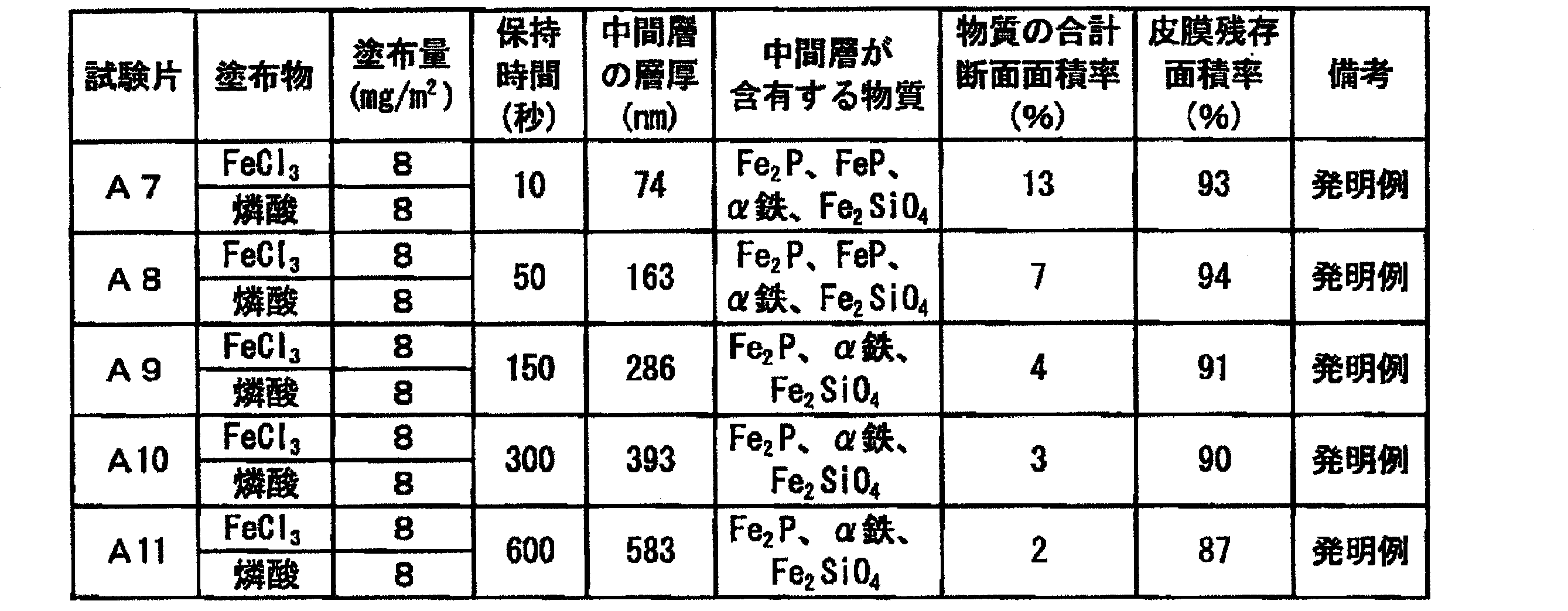
実施例1と同様にして、平滑表面を有する方向性電磁鋼板を作製した。この方向性電磁鋼板の表面に、表4に示す塗布物を含む水溶液を、水を除いた塗布物の量が、表4に示す塗布量となるように塗布し、水素:窒素が75%:25%で、露点が-20℃の雰囲気で、6℃/秒の昇温速度で700℃まで加熱した。なお、表4に示す全ての塗布物における燐酸と金属元素を含む化合物との比率は、質量比で2:1~1:2の範囲内とした。
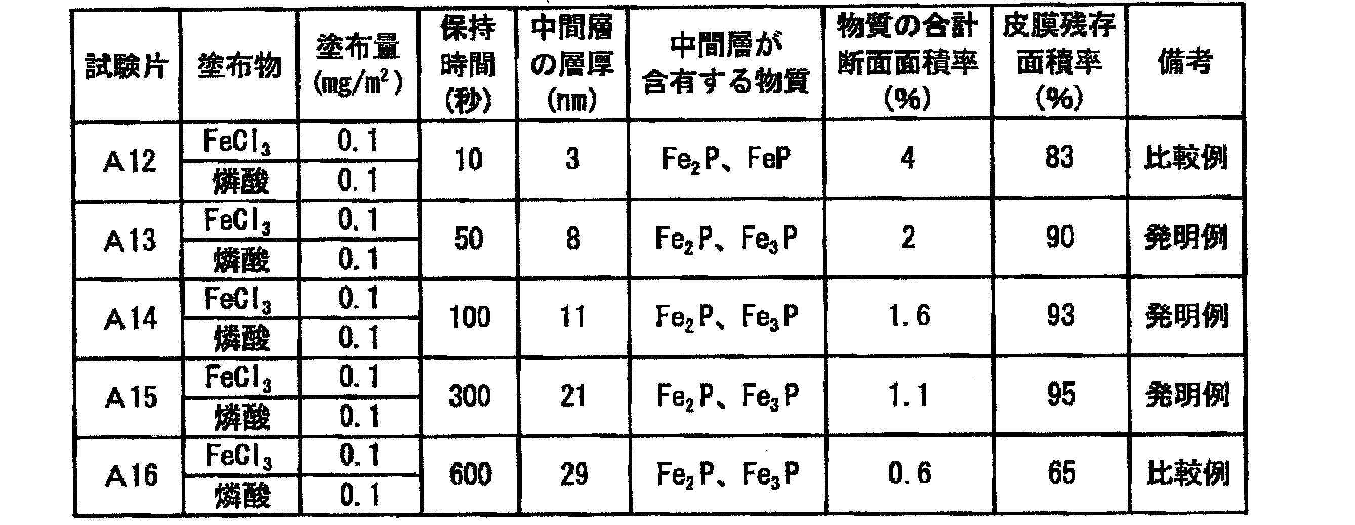
表1に成分組成を示す珪素鋼片(スラブ)を1150℃で60分均熱して熱間圧延に供し、2.3mm厚の熱延鋼板とした。次いで、この熱延鋼板に、1120℃で200秒保持した後、直ちに、900℃に120秒に保持して急冷する焼鈍を施し、酸洗後、冷間圧延に供し、最終板厚0.27mmの冷延鋼板とした。

2 フォルステライト被膜
3 絶縁被膜
4 中間層
5 金属燐化物
Claims (10)
- 鋼板と、
前記鋼板の上に配されたSi及びOを含む中間層と、
前記中間層の上に配された絶縁被膜と
を有する方向性電磁鋼板であって、
前記中間層が金属燐化物を含有し、
前記中間層の層厚が4nm以上であり、
前記金属燐化物の存在量が、前記中間層の断面における断面面積率で1~30%である
ことを特徴とする方向性電磁鋼板。 - 前記金属燐化物が、Fe3P、Fe2P、及び、FePの1種又は2種以上のFe燐化物であることを特徴とする請求項1に記載の方向性電磁鋼板。
- 前記中間層が、前記金属燐化物に加えてα鉄及び/又は珪酸鉄を含有することを特徴とする請求項1又は2に記載の方向性電磁鋼板。
- 前記金属燐化物、及び、α鉄及び/又は珪酸鉄の合計の存在量が、前記中間層の断面における断面面積率で1~30%であることを特徴とする請求項3に記載の方向性電磁鋼板。
- 前記中間層の層厚が400nm未満であることを特徴とする請求項1~4のいずれか1項に記載の方向性電磁鋼板。
- 前記絶縁被膜の膜厚が0.1~10μmであることを特徴とする請求項1~5のいずれか1項に記載の方向性電磁鋼板。
- 前記鋼板の表面粗度が、算術平均粗さRaで0.5μm以下であることを特徴とする請求項1~6のいずれか1項に記載の方向性電磁鋼板。
- 請求項1~7のいずれか1項に記載の方向性電磁鋼板の製造方法であって、
鋼片を熱間圧延して熱延鋼板を得る工程と、
前記熱延鋼板を冷間圧延して冷延鋼板を得る工程と、
前記冷延鋼板を脱炭焼鈍して、前記冷延鋼板の表面に酸化層を形成する工程と、
前記酸化層を有する前記冷延鋼板の表面に焼鈍分離剤を塗布する工程と、
前記焼鈍分離剤を乾燥させてから、前記冷延鋼板を巻き取る工程と、
巻き取られた前記冷延鋼板を仕上げ焼鈍する工程と、
第一の溶液を塗布する工程と、
前記第一の溶液が塗布された前記冷延鋼板をさらに焼鈍して、金属燐化物を含む中間層を形成する工程と、
前記中間層の表面に第二の溶液を塗布する工程と、
前記第二の溶液が塗布された前記冷延鋼板に焼き付けをする工程と、
を備え、
前記第一の溶液が、燐酸と金属化合物とを含み、前記燐酸と前記金属化合物との質量比が2:1~1:2であり、
前記中間層を形成するための焼鈍において、焼鈍温度を600~1150℃とし、焼鈍時間を10~600秒とし、焼鈍雰囲気における露点を-20~2℃とし、前記焼鈍雰囲気における水素量及び窒素量の比率を75%:25%とし、
前記金属燐化物の存在量が、前記中間層の断面における断面面積率で1~30%となるように前記第一の溶液の塗布量を制御する
ことを特徴とする方向性電磁鋼板の製造方法。 - さらに、前記第一の溶液を塗布する前に、前記仕上げ焼鈍によって生じた無機鉱物質被膜を除去する工程を備え、
前記焼鈍分離剤がマグネシアを主成分とする
ことを特徴とする請求項8に記載の方向性電磁鋼板の製造方法。 - さらに、前記冷間圧延の前に、前記熱延鋼板を焼鈍する工程を備えることを特徴とする請求項8又は9に記載の方向性電磁鋼板の製造方法。
Priority Applications (7)
| Application Number | Priority Date | Filing Date | Title |
|---|---|---|---|
| EP18831932.1A EP3653752A4 (en) | 2017-07-13 | 2018-07-13 | ORIENTED ELECTROMAGNETIC STEEL SHEET AND MANUFACTURING METHOD FOR ORIENTED ELECTROMAGNETIC STEEL SHEET |
| JP2019529815A JP6828820B2 (ja) | 2017-07-13 | 2018-07-13 | 方向性電磁鋼板、及び方向性電磁鋼板の製造方法 |
| RU2020100875A RU2730822C1 (ru) | 2017-07-13 | 2018-07-13 | Электротехнический стальной лист с ориентированной зеренной структурой и способ производства электротехнического стального листа с ориентированной зеренной структурой |
| US16/628,951 US11060159B2 (en) | 2017-07-13 | 2018-07-13 | Grain-oriented electrical steel sheet and method of manufacturing grain-oriented electrical steel sheet |
| CN201880045384.5A CN110869531B (zh) | 2017-07-13 | 2018-07-13 | 方向性电磁钢板及方向性电磁钢板的制造方法 |
| KR1020207001780A KR102419870B1 (ko) | 2017-07-13 | 2018-07-13 | 방향성 전자 강판 및 방향성 전자 강판의 제조 방법 |
| BR112020000278-0A BR112020000278B1 (pt) | 2017-07-13 | 2018-07-13 | Chapa de aço elétrico com grão orientado e método de produção da chapa de aço elétrico com grão orientado |
Applications Claiming Priority (2)
| Application Number | Priority Date | Filing Date | Title |
|---|---|---|---|
| JP2017-137419 | 2017-07-13 | ||
| JP2017137419 | 2017-07-13 |
Publications (1)
| Publication Number | Publication Date |
|---|---|
| WO2019013347A1 true WO2019013347A1 (ja) | 2019-01-17 |
Family
ID=65002099
Family Applications (1)
| Application Number | Title | Priority Date | Filing Date |
|---|---|---|---|
| PCT/JP2018/026611 Ceased WO2019013347A1 (ja) | 2017-07-13 | 2018-07-13 | 方向性電磁鋼板、及び方向性電磁鋼板の製造方法 |
Country Status (7)
| Country | Link |
|---|---|
| US (1) | US11060159B2 (ja) |
| EP (1) | EP3653752A4 (ja) |
| JP (1) | JP6828820B2 (ja) |
| KR (1) | KR102419870B1 (ja) |
| CN (1) | CN110869531B (ja) |
| RU (1) | RU2730822C1 (ja) |
| WO (1) | WO2019013347A1 (ja) |
Cited By (2)
| Publication number | Priority date | Publication date | Assignee | Title |
|---|---|---|---|---|
| WO2020149325A1 (ja) * | 2019-01-16 | 2020-07-23 | 日本製鉄株式会社 | 方向性電磁鋼板の製造方法 |
| JPWO2024214818A1 (ja) * | 2023-04-12 | 2024-10-17 |
Families Citing this family (7)
| Publication number | Priority date | Publication date | Assignee | Title |
|---|---|---|---|---|
| CN109609747B (zh) * | 2018-12-11 | 2022-01-25 | 信达科创(唐山)石油设备有限公司 | 一种连续油管的均质处理工艺 |
| EP3913091A4 (en) | 2019-01-16 | 2022-10-12 | Nippon Steel Corporation | PROCESS FOR THE MANUFACTURE OF A CORNORATED ELECTRICAL STEEL SHEET |
| PL3913086T3 (pl) | 2019-01-16 | 2024-10-28 | Nippon Steel Corporation | Blacha cienka ze stali elektrotechnicznej o ziarnach zorientowanych mająca doskonałą przyczepność powłoki izolacyjnej bez powłoki forsterytowej |
| WO2020149346A1 (ja) * | 2019-01-16 | 2020-07-23 | 日本製鉄株式会社 | 方向性電磁鋼板の製造方法 |
| US12338504B2 (en) * | 2019-01-16 | 2025-06-24 | Nippon Steel Corporation | Method for producing grain-oriented electrical steel sheet |
| EP4350033A4 (en) * | 2021-05-28 | 2024-09-18 | Nippon Steel Corporation | Grain-oriented electromagnetic steel sheet |
| CN117344210A (zh) * | 2022-06-29 | 2024-01-05 | 宝山钢铁股份有限公司 | 取向硅钢及其制造方法 |
Citations (17)
| Publication number | Priority date | Publication date | Assignee | Title |
|---|---|---|---|---|
| JPS4996920A (ja) | 1973-01-22 | 1974-09-13 | ||
| JPS62103374A (ja) * | 1985-07-23 | 1987-05-13 | Kawasaki Steel Corp | 磁気特性の優れた一方向性けい素鋼板 |
| JPS62218582A (ja) * | 1986-01-07 | 1987-09-25 | モ−トン サイオコ−ル,インコ−ポレイテイド | けい素鋼焼鈍用分離被膜としての酸化マグネシウムとジルコニウム化合物の混合物 |
| JPH03130376A (ja) | 1989-10-17 | 1991-06-04 | Kawasaki Steel Corp | 磁気特性の極めて良好な一方向性けい素鋼板の製造方法 |
| JPH05279747A (ja) | 1992-04-02 | 1993-10-26 | Nippon Steel Corp | 方向性電磁鋼板の絶縁皮膜形成方法 |
| JPH06184762A (ja) | 1992-08-25 | 1994-07-05 | Nippon Steel Corp | 一方向性珪素鋼板の絶縁皮膜形成方法 |
| JPH07278833A (ja) | 1994-04-15 | 1995-10-24 | Nippon Steel Corp | 一方向性珪素鋼板の絶縁皮膜形成方法 |
| JPH08191010A (ja) | 1995-01-06 | 1996-07-23 | Kawasaki Steel Corp | 磁気特性の良好な方向性けい素鋼板及びその製造方法 |
| JPH0978252A (ja) | 1995-09-13 | 1997-03-25 | Nippon Steel Corp | 一方向性珪素鋼板の絶縁皮膜形成方法 |
| JPH11209891A (ja) | 1997-10-14 | 1999-08-03 | Nippon Steel Corp | 電磁鋼板の絶縁皮膜形成方法 |
| JP2002322566A (ja) | 2001-04-23 | 2002-11-08 | Nippon Steel Corp | 張力付与性絶縁皮膜の皮膜密着性に優れる一方向性珪素鋼板とその製造方法 |
| JP2002348643A (ja) | 2001-05-22 | 2002-12-04 | Nippon Steel Corp | 張力付与性絶縁皮膜の皮膜密着性に優れる一方向性珪素鋼板とその製造方法 |
| JP2002363763A (ja) | 2001-06-08 | 2002-12-18 | Nippon Steel Corp | 絶縁皮膜密着性に優れる一方向性珪素鋼板とその製造方法 |
| JP2003171773A (ja) | 2001-12-04 | 2003-06-20 | Nippon Steel Corp | 張力皮膜を有する一方向性珪素鋼板 |
| JP2003313644A (ja) | 2002-04-25 | 2003-11-06 | Nippon Steel Corp | 張力付与性絶縁皮膜の鋼板密着性に優れる一方向性珪素鋼板とその製造方法 |
| JP2004315880A (ja) | 2003-04-15 | 2004-11-11 | Nippon Steel Corp | 一方向性電磁鋼板の絶縁皮膜形成方法、および皮膜密着性に優れた絶縁皮膜を有する一方向性電磁鋼板 |
| JP2017137419A (ja) | 2016-02-03 | 2017-08-10 | 国立大学法人豊橋技術科学大学 | ポリ乳酸多孔質化ペレット及びその製造方法 |
Family Cites Families (20)
| Publication number | Priority date | Publication date | Assignee | Title |
|---|---|---|---|---|
| FR2397120A1 (fr) * | 1977-07-04 | 1979-02-02 | Lewiner Jacques | Perfectionnements aux transducteurs electromecaniques |
| IT1182608B (it) | 1984-10-15 | 1987-10-05 | Nippon Steel Corp | Lamiera di acciaio elettrico a grana orientata avente una bassa perdita di potenza e metodo per la sua fabbricazione |
| EP0193324B1 (en) * | 1985-02-22 | 1989-10-11 | Kawasaki Steel Corporation | Extra-low iron loss grain oriented silicon steel sheets |
| US4713123A (en) * | 1985-02-22 | 1987-12-15 | Kawasaki Steel Corporation | Method of producing extra-low iron loss grain oriented silicon steel sheets |
| JP2814437B2 (ja) | 1987-07-21 | 1998-10-22 | 川崎製鉄 株式会社 | 表面性状に優れた方向性けい素鋼板の製造方法 |
| DE69332394T2 (de) | 1992-07-02 | 2003-06-12 | Nippon Steel Corp., Tokio/Tokyo | Kornorientiertes Elektroblech mit hoher Flussdichte und geringen Eisenverlusten und Herstellungsverfahren |
| DE4311151C1 (de) * | 1993-04-05 | 1994-07-28 | Thyssen Stahl Ag | Verfahren zur Herstellung von kornorientierten Elektroblechen mit verbesserten Ummagnetisierungsverlusten |
| US5580371A (en) * | 1996-05-13 | 1996-12-03 | International Zinc, Coatings & Chemical Corp. | Corrosion resistant, weldable coating compositions |
| RU2181777C2 (ru) * | 1999-12-23 | 2002-04-27 | Федеральное государственное унитарное предприятие Российского космического агентства "Опытное конструкторское бюро "Факел" | Способ изготовления и термической обработки деталей из магнитомягких сталей магнитных систем электрических реактивных двигателей малой тяги |
| EP1382717B1 (en) * | 2001-04-23 | 2007-07-18 | Nippon Steel Corporation | Unidirectional silicon steel sheet excellent in adhesion of insulating coating film imparting tensile force |
| DE10130308B4 (de) | 2001-06-22 | 2005-05-12 | Thyssenkrupp Electrical Steel Ebg Gmbh | Kornorientiertes Elektroblech mit einer elektrisch isolierenden Beschichtung |
| US20060110609A1 (en) * | 2004-11-19 | 2006-05-25 | Eaton Harry E | Protective coatings |
| JP4878788B2 (ja) * | 2005-07-14 | 2012-02-15 | 新日本製鐵株式会社 | クロムを含有しない電磁鋼板用絶縁被膜剤 |
| EP1752548B1 (de) * | 2005-08-03 | 2016-02-03 | ThyssenKrupp Steel Europe AG | Verfahren zur Herstellung von kornorientiertem Elektroband |
| US7998284B2 (en) * | 2006-05-19 | 2011-08-16 | Nippon Steel Corporation | Grain-oriented electrical steel sheet having high tensile strength insulating film and method of treatment of such insulating film |
| DE102010038038A1 (de) * | 2010-10-07 | 2012-04-12 | Thyssenkrupp Electrical Steel Gmbh | Verfahren zum Erzeugen einer Isolationsbeschichtung auf einem kornorientierten Elektro-Stahlflachprodukt und mit einer solchen Isolationsbeschichtung beschichtetes Elektro-Stahlflachprodukt |
| KR101223115B1 (ko) | 2010-12-23 | 2013-01-17 | 주식회사 포스코 | 자성이 우수한 방향성 전기강판 및 이의 제조방법 |
| EP2799594B1 (en) * | 2011-12-28 | 2018-10-31 | JFE Steel Corporation | Directional electromagnetic steel sheet with coating, and method for producing same |
| KR102240346B1 (ko) * | 2013-02-08 | 2021-04-14 | 닛폰세이테츠 가부시키가이샤 | 절연 코팅을 형성하기 위한 용액 및 방향성 전기 강 시트 |
| RU2621523C1 (ru) * | 2013-09-19 | 2017-06-06 | ДжФЕ СТИЛ КОРПОРЕЙШН | Лист из текстурированной электротехнической стали и способ его изготовления |
-
2018
- 2018-07-13 JP JP2019529815A patent/JP6828820B2/ja active Active
- 2018-07-13 US US16/628,951 patent/US11060159B2/en active Active
- 2018-07-13 RU RU2020100875A patent/RU2730822C1/ru active
- 2018-07-13 EP EP18831932.1A patent/EP3653752A4/en active Pending
- 2018-07-13 WO PCT/JP2018/026611 patent/WO2019013347A1/ja not_active Ceased
- 2018-07-13 KR KR1020207001780A patent/KR102419870B1/ko active Active
- 2018-07-13 CN CN201880045384.5A patent/CN110869531B/zh active Active
Patent Citations (17)
| Publication number | Priority date | Publication date | Assignee | Title |
|---|---|---|---|---|
| JPS4996920A (ja) | 1973-01-22 | 1974-09-13 | ||
| JPS62103374A (ja) * | 1985-07-23 | 1987-05-13 | Kawasaki Steel Corp | 磁気特性の優れた一方向性けい素鋼板 |
| JPS62218582A (ja) * | 1986-01-07 | 1987-09-25 | モ−トン サイオコ−ル,インコ−ポレイテイド | けい素鋼焼鈍用分離被膜としての酸化マグネシウムとジルコニウム化合物の混合物 |
| JPH03130376A (ja) | 1989-10-17 | 1991-06-04 | Kawasaki Steel Corp | 磁気特性の極めて良好な一方向性けい素鋼板の製造方法 |
| JPH05279747A (ja) | 1992-04-02 | 1993-10-26 | Nippon Steel Corp | 方向性電磁鋼板の絶縁皮膜形成方法 |
| JPH06184762A (ja) | 1992-08-25 | 1994-07-05 | Nippon Steel Corp | 一方向性珪素鋼板の絶縁皮膜形成方法 |
| JPH07278833A (ja) | 1994-04-15 | 1995-10-24 | Nippon Steel Corp | 一方向性珪素鋼板の絶縁皮膜形成方法 |
| JPH08191010A (ja) | 1995-01-06 | 1996-07-23 | Kawasaki Steel Corp | 磁気特性の良好な方向性けい素鋼板及びその製造方法 |
| JPH0978252A (ja) | 1995-09-13 | 1997-03-25 | Nippon Steel Corp | 一方向性珪素鋼板の絶縁皮膜形成方法 |
| JPH11209891A (ja) | 1997-10-14 | 1999-08-03 | Nippon Steel Corp | 電磁鋼板の絶縁皮膜形成方法 |
| JP2002322566A (ja) | 2001-04-23 | 2002-11-08 | Nippon Steel Corp | 張力付与性絶縁皮膜の皮膜密着性に優れる一方向性珪素鋼板とその製造方法 |
| JP2002348643A (ja) | 2001-05-22 | 2002-12-04 | Nippon Steel Corp | 張力付与性絶縁皮膜の皮膜密着性に優れる一方向性珪素鋼板とその製造方法 |
| JP2002363763A (ja) | 2001-06-08 | 2002-12-18 | Nippon Steel Corp | 絶縁皮膜密着性に優れる一方向性珪素鋼板とその製造方法 |
| JP2003171773A (ja) | 2001-12-04 | 2003-06-20 | Nippon Steel Corp | 張力皮膜を有する一方向性珪素鋼板 |
| JP2003313644A (ja) | 2002-04-25 | 2003-11-06 | Nippon Steel Corp | 張力付与性絶縁皮膜の鋼板密着性に優れる一方向性珪素鋼板とその製造方法 |
| JP2004315880A (ja) | 2003-04-15 | 2004-11-11 | Nippon Steel Corp | 一方向性電磁鋼板の絶縁皮膜形成方法、および皮膜密着性に優れた絶縁皮膜を有する一方向性電磁鋼板 |
| JP2017137419A (ja) | 2016-02-03 | 2017-08-10 | 国立大学法人豊橋技術科学大学 | ポリ乳酸多孔質化ペレット及びその製造方法 |
Non-Patent Citations (1)
| Title |
|---|
| See also references of EP3653752A4 |
Cited By (3)
| Publication number | Priority date | Publication date | Assignee | Title |
|---|---|---|---|---|
| WO2020149325A1 (ja) * | 2019-01-16 | 2020-07-23 | 日本製鉄株式会社 | 方向性電磁鋼板の製造方法 |
| JPWO2024214818A1 (ja) * | 2023-04-12 | 2024-10-17 | ||
| WO2024214818A1 (ja) * | 2023-04-12 | 2024-10-17 | 日本製鉄株式会社 | 方向性電磁鋼板および絶縁被膜の形成方法 |
Also Published As
| Publication number | Publication date |
|---|---|
| US11060159B2 (en) | 2021-07-13 |
| CN110869531A (zh) | 2020-03-06 |
| JPWO2019013347A1 (ja) | 2020-07-27 |
| KR20200018669A (ko) | 2020-02-19 |
| RU2730822C1 (ru) | 2020-08-26 |
| US20200123626A1 (en) | 2020-04-23 |
| BR112020000278A2 (pt) | 2020-07-14 |
| JP6828820B2 (ja) | 2021-02-10 |
| EP3653752A1 (en) | 2020-05-20 |
| CN110869531B (zh) | 2022-06-03 |
| EP3653752A4 (en) | 2021-05-12 |
| KR102419870B1 (ko) | 2022-07-13 |
Similar Documents
| Publication | Publication Date | Title |
|---|---|---|
| JP6828820B2 (ja) | 方向性電磁鋼板、及び方向性電磁鋼板の製造方法 | |
| EP3653758B1 (en) | Grain-oriented electrical steel sheet | |
| JP7188458B2 (ja) | 方向性電磁鋼板およびその製造方法 | |
| CN117157427A (zh) | 方向性电磁钢板及绝缘被膜的形成方法 | |
| WO2020149340A1 (ja) | 方向性電磁鋼板およびその製造方法 | |
| CN113383093B (zh) | 方向性电磁钢板及其制造方法 | |
| KR20240164542A (ko) | 방향성 전자 강판 및 그 제조 방법 | |
| KR102412320B1 (ko) | 방향성 전자 강판 | |
| JP7260798B2 (ja) | 方向性電磁鋼板の製造方法 | |
| JP7188105B2 (ja) | 方向性電磁鋼板 | |
| RU2776382C1 (ru) | Лист анизотропной электротехнической стали и способ его производства | |
| WO2023204266A1 (ja) | 方向性電磁鋼板およびその製造方法 | |
| WO2023204267A1 (ja) | 方向性電磁鋼板およびその製造方法 | |
| BR112020000278B1 (pt) | Chapa de aço elétrico com grão orientado e método de produção da chapa de aço elétrico com grão orientado |
Legal Events
| Date | Code | Title | Description |
|---|---|---|---|
| 121 | Ep: the epo has been informed by wipo that ep was designated in this application |
Ref document number: 18831932 Country of ref document: EP Kind code of ref document: A1 |
|
| ENP | Entry into the national phase |
Ref document number: 2019529815 Country of ref document: JP Kind code of ref document: A |
|
| NENP | Non-entry into the national phase |
Ref country code: DE |
|
| REG | Reference to national code |
Ref country code: BR Ref legal event code: B01A Ref document number: 112020000278 Country of ref document: BR |
|
| ENP | Entry into the national phase |
Ref document number: 20207001780 Country of ref document: KR Kind code of ref document: A |
|
| ENP | Entry into the national phase |
Ref document number: 2018831932 Country of ref document: EP Effective date: 20200213 |
|
| ENP | Entry into the national phase |
Ref document number: 112020000278 Country of ref document: BR Kind code of ref document: A2 Effective date: 20200106 |