WO2019016845A1 - 給湯装置 - Google Patents
給湯装置 Download PDFInfo
- Publication number
- WO2019016845A1 WO2019016845A1 PCT/JP2017/025839 JP2017025839W WO2019016845A1 WO 2019016845 A1 WO2019016845 A1 WO 2019016845A1 JP 2017025839 W JP2017025839 W JP 2017025839W WO 2019016845 A1 WO2019016845 A1 WO 2019016845A1
- Authority
- WO
- WIPO (PCT)
- Prior art keywords
- hot water
- heat medium
- storage tank
- water storage
- pump
- Prior art date
- Legal status (The legal status is an assumption and is not a legal conclusion. Google has not performed a legal analysis and makes no representation as to the accuracy of the status listed.)
- Ceased
Links
Images










Classifications
-
- F—MECHANICAL ENGINEERING; LIGHTING; HEATING; WEAPONS; BLASTING
- F24—HEATING; RANGES; VENTILATING
- F24D—DOMESTIC- OR SPACE-HEATING SYSTEMS, e.g. CENTRAL HEATING SYSTEMS; DOMESTIC HOT-WATER SUPPLY SYSTEMS; ELEMENTS OR COMPONENTS THEREFOR
- F24D3/00—Hot-water central heating systems
- F24D3/08—Hot-water central heating systems in combination with systems for domestic hot-water supply
- F24D3/082—Hot water storage tanks specially adapted therefor
-
- F—MECHANICAL ENGINEERING; LIGHTING; HEATING; WEAPONS; BLASTING
- F24—HEATING; RANGES; VENTILATING
- F24D—DOMESTIC- OR SPACE-HEATING SYSTEMS, e.g. CENTRAL HEATING SYSTEMS; DOMESTIC HOT-WATER SUPPLY SYSTEMS; ELEMENTS OR COMPONENTS THEREFOR
- F24D19/00—Details
- F24D19/10—Arrangement or mounting of control or safety devices
- F24D19/1006—Arrangement or mounting of control or safety devices for water heating systems
- F24D19/1009—Arrangement or mounting of control or safety devices for water heating systems for central heating
- F24D19/1012—Arrangement or mounting of control or safety devices for water heating systems for central heating by regulating the speed of a pump
-
- F—MECHANICAL ENGINEERING; LIGHTING; HEATING; WEAPONS; BLASTING
- F24—HEATING; RANGES; VENTILATING
- F24D—DOMESTIC- OR SPACE-HEATING SYSTEMS, e.g. CENTRAL HEATING SYSTEMS; DOMESTIC HOT-WATER SUPPLY SYSTEMS; ELEMENTS OR COMPONENTS THEREFOR
- F24D19/00—Details
- F24D19/10—Arrangement or mounting of control or safety devices
- F24D19/1006—Arrangement or mounting of control or safety devices for water heating systems
- F24D19/1066—Arrangement or mounting of control or safety devices for water heating systems for the combination of central heating and domestic hot water
- F24D19/1072—Arrangement or mounting of control or safety devices for water heating systems for the combination of central heating and domestic hot water the system uses a heat pump
-
- F—MECHANICAL ENGINEERING; LIGHTING; HEATING; WEAPONS; BLASTING
- F24—HEATING; RANGES; VENTILATING
- F24D—DOMESTIC- OR SPACE-HEATING SYSTEMS, e.g. CENTRAL HEATING SYSTEMS; DOMESTIC HOT-WATER SUPPLY SYSTEMS; ELEMENTS OR COMPONENTS THEREFOR
- F24D3/00—Hot-water central heating systems
- F24D3/18—Hot-water central heating systems using heat pumps
-
- F—MECHANICAL ENGINEERING; LIGHTING; HEATING; WEAPONS; BLASTING
- F24—HEATING; RANGES; VENTILATING
- F24H—FLUID HEATERS, e.g. WATER OR AIR HEATERS, HAVING HEAT-GENERATING MEANS, e.g. HEAT PUMPS, IN GENERAL
- F24H15/00—Control of fluid heaters
- F24H15/20—Control of fluid heaters characterised by control inputs
- F24H15/212—Temperature of the water
- F24H15/223—Temperature of the water in the water storage tank
- F24H15/225—Temperature of the water in the water storage tank at different heights of the tank
-
- F—MECHANICAL ENGINEERING; LIGHTING; HEATING; WEAPONS; BLASTING
- F24—HEATING; RANGES; VENTILATING
- F24H—FLUID HEATERS, e.g. WATER OR AIR HEATERS, HAVING HEAT-GENERATING MEANS, e.g. HEAT PUMPS, IN GENERAL
- F24H15/00—Control of fluid heaters
- F24H15/30—Control of fluid heaters characterised by control outputs; characterised by the components to be controlled
- F24H15/335—Control of pumps, e.g. on-off control
- F24H15/34—Control of the speed of pumps
-
- F—MECHANICAL ENGINEERING; LIGHTING; HEATING; WEAPONS; BLASTING
- F24—HEATING; RANGES; VENTILATING
- F24H—FLUID HEATERS, e.g. WATER OR AIR HEATERS, HAVING HEAT-GENERATING MEANS, e.g. HEAT PUMPS, IN GENERAL
- F24H15/00—Control of fluid heaters
- F24H15/30—Control of fluid heaters characterised by control outputs; characterised by the components to be controlled
- F24H15/375—Control of heat pumps
- F24H15/38—Control of compressors of heat pumps
-
- F—MECHANICAL ENGINEERING; LIGHTING; HEATING; WEAPONS; BLASTING
- F24—HEATING; RANGES; VENTILATING
- F24H—FLUID HEATERS, e.g. WATER OR AIR HEATERS, HAVING HEAT-GENERATING MEANS, e.g. HEAT PUMPS, IN GENERAL
- F24H15/00—Control of fluid heaters
- F24H15/30—Control of fluid heaters characterised by control outputs; characterised by the components to be controlled
- F24H15/375—Control of heat pumps
- F24H15/385—Control of expansion valves of heat pumps
-
- F—MECHANICAL ENGINEERING; LIGHTING; HEATING; WEAPONS; BLASTING
- F24—HEATING; RANGES; VENTILATING
- F24H—FLUID HEATERS, e.g. WATER OR AIR HEATERS, HAVING HEAT-GENERATING MEANS, e.g. HEAT PUMPS, IN GENERAL
- F24H4/00—Fluid heaters characterised by the use of heat pumps
- F24H4/02—Water heaters
- F24H4/04—Storage heaters
-
- F—MECHANICAL ENGINEERING; LIGHTING; HEATING; WEAPONS; BLASTING
- F24—HEATING; RANGES; VENTILATING
- F24D—DOMESTIC- OR SPACE-HEATING SYSTEMS, e.g. CENTRAL HEATING SYSTEMS; DOMESTIC HOT-WATER SUPPLY SYSTEMS; ELEMENTS OR COMPONENTS THEREFOR
- F24D2200/00—Heat sources or energy sources
- F24D2200/12—Heat pump
-
- F—MECHANICAL ENGINEERING; LIGHTING; HEATING; WEAPONS; BLASTING
- F24—HEATING; RANGES; VENTILATING
- F24D—DOMESTIC- OR SPACE-HEATING SYSTEMS, e.g. CENTRAL HEATING SYSTEMS; DOMESTIC HOT-WATER SUPPLY SYSTEMS; ELEMENTS OR COMPONENTS THEREFOR
- F24D2200/00—Heat sources or energy sources
- F24D2200/12—Heat pump
- F24D2200/123—Compression type heat pumps
-
- F—MECHANICAL ENGINEERING; LIGHTING; HEATING; WEAPONS; BLASTING
- F24—HEATING; RANGES; VENTILATING
- F24D—DOMESTIC- OR SPACE-HEATING SYSTEMS, e.g. CENTRAL HEATING SYSTEMS; DOMESTIC HOT-WATER SUPPLY SYSTEMS; ELEMENTS OR COMPONENTS THEREFOR
- F24D2220/00—Components of central heating installations excluding heat sources
- F24D2220/08—Storage tanks
-
- F—MECHANICAL ENGINEERING; LIGHTING; HEATING; WEAPONS; BLASTING
- F24—HEATING; RANGES; VENTILATING
- F24D—DOMESTIC- OR SPACE-HEATING SYSTEMS, e.g. CENTRAL HEATING SYSTEMS; DOMESTIC HOT-WATER SUPPLY SYSTEMS; ELEMENTS OR COMPONENTS THEREFOR
- F24D2240/00—Characterizing positions, e.g. of sensors, inlets, outlets
- F24D2240/26—Vertically distributed at fixed positions, e.g. multiple sensors distributed over the height of a tank, or a vertical inlet distribution pipe having a plurality of orifices
-
- F—MECHANICAL ENGINEERING; LIGHTING; HEATING; WEAPONS; BLASTING
- F24—HEATING; RANGES; VENTILATING
- F24H—FLUID HEATERS, e.g. WATER OR AIR HEATERS, HAVING HEAT-GENERATING MEANS, e.g. HEAT PUMPS, IN GENERAL
- F24H15/00—Control of fluid heaters
- F24H15/20—Control of fluid heaters characterised by control inputs
- F24H15/227—Temperature of the refrigerant in heat pump cycles
- F24H15/232—Temperature of the refrigerant in heat pump cycles at the condenser
-
- F—MECHANICAL ENGINEERING; LIGHTING; HEATING; WEAPONS; BLASTING
- F24—HEATING; RANGES; VENTILATING
- F24H—FLUID HEATERS, e.g. WATER OR AIR HEATERS, HAVING HEAT-GENERATING MEANS, e.g. HEAT PUMPS, IN GENERAL
- F24H15/00—Control of fluid heaters
- F24H15/20—Control of fluid heaters characterised by control inputs
- F24H15/242—Pressure
-
- F—MECHANICAL ENGINEERING; LIGHTING; HEATING; WEAPONS; BLASTING
- F24—HEATING; RANGES; VENTILATING
- F24H—FLUID HEATERS, e.g. WATER OR AIR HEATERS, HAVING HEAT-GENERATING MEANS, e.g. HEAT PUMPS, IN GENERAL
- F24H15/00—Control of fluid heaters
- F24H15/30—Control of fluid heaters characterised by control outputs; characterised by the components to be controlled
- F24H15/305—Control of valves
- F24H15/32—Control of valves of switching valves
-
- F—MECHANICAL ENGINEERING; LIGHTING; HEATING; WEAPONS; BLASTING
- F24—HEATING; RANGES; VENTILATING
- F24H—FLUID HEATERS, e.g. WATER OR AIR HEATERS, HAVING HEAT-GENERATING MEANS, e.g. HEAT PUMPS, IN GENERAL
- F24H15/00—Control of fluid heaters
- F24H15/30—Control of fluid heaters characterised by control outputs; characterised by the components to be controlled
- F24H15/345—Control of fans, e.g. on-off control
-
- F—MECHANICAL ENGINEERING; LIGHTING; HEATING; WEAPONS; BLASTING
- F24—HEATING; RANGES; VENTILATING
- F24H—FLUID HEATERS, e.g. WATER OR AIR HEATERS, HAVING HEAT-GENERATING MEANS, e.g. HEAT PUMPS, IN GENERAL
- F24H15/00—Control of fluid heaters
- F24H15/40—Control of fluid heaters characterised by the type of controllers
- F24H15/414—Control of fluid heaters characterised by the type of controllers using electronic processing, e.g. computer-based
- F24H15/421—Control of fluid heaters characterised by the type of controllers using electronic processing, e.g. computer-based using pre-stored data
-
- F—MECHANICAL ENGINEERING; LIGHTING; HEATING; WEAPONS; BLASTING
- F24—HEATING; RANGES; VENTILATING
- F24H—FLUID HEATERS, e.g. WATER OR AIR HEATERS, HAVING HEAT-GENERATING MEANS, e.g. HEAT PUMPS, IN GENERAL
- F24H15/00—Control of fluid heaters
- F24H15/40—Control of fluid heaters characterised by the type of controllers
- F24H15/414—Control of fluid heaters characterised by the type of controllers using electronic processing, e.g. computer-based
- F24H15/45—Control of fluid heaters characterised by the type of controllers using electronic processing, e.g. computer-based remotely accessible
-
- Y—GENERAL TAGGING OF NEW TECHNOLOGICAL DEVELOPMENTS; GENERAL TAGGING OF CROSS-SECTIONAL TECHNOLOGIES SPANNING OVER SEVERAL SECTIONS OF THE IPC; TECHNICAL SUBJECTS COVERED BY FORMER USPC CROSS-REFERENCE ART COLLECTIONS [XRACs] AND DIGESTS
- Y02—TECHNOLOGIES OR APPLICATIONS FOR MITIGATION OR ADAPTATION AGAINST CLIMATE CHANGE
- Y02B—CLIMATE CHANGE MITIGATION TECHNOLOGIES RELATED TO BUILDINGS, e.g. HOUSING, HOUSE APPLIANCES OR RELATED END-USER APPLICATIONS
- Y02B30/00—Energy efficient heating, ventilation or air conditioning [HVAC]
- Y02B30/12—Hot water central heating systems using heat pumps
-
- Y—GENERAL TAGGING OF NEW TECHNOLOGICAL DEVELOPMENTS; GENERAL TAGGING OF CROSS-SECTIONAL TECHNOLOGIES SPANNING OVER SEVERAL SECTIONS OF THE IPC; TECHNICAL SUBJECTS COVERED BY FORMER USPC CROSS-REFERENCE ART COLLECTIONS [XRACs] AND DIGESTS
- Y02—TECHNOLOGIES OR APPLICATIONS FOR MITIGATION OR ADAPTATION AGAINST CLIMATE CHANGE
- Y02B—CLIMATE CHANGE MITIGATION TECHNOLOGIES RELATED TO BUILDINGS, e.g. HOUSING, HOUSE APPLIANCES OR RELATED END-USER APPLICATIONS
- Y02B30/00—Energy efficient heating, ventilation or air conditioning [HVAC]
- Y02B30/70—Efficient control or regulation technologies, e.g. for control of refrigerant flow, motor or heating
Definitions
- the present invention relates to a hot water supply apparatus, and more particularly to a hot water supply apparatus provided with a pump for transferring a heat medium to a hot water storage tank.
- a conventional hot water supply apparatus includes a hot water storage tank for storing a heat medium, a pump for conveying the heat medium to the hot water storage tank, and a thermistor for detecting the temperature of the hot water storage tank (for example, Reference 1).
- the first temperature distribution of the heat medium in the hot water storage tank when the temperature of the heat medium in the hot water storage tank is lowered due to the heat release of the hot water storage tank is the temperature of the heat medium in the hot water storage tank Is different from the second temperature distribution of the heat medium in the hot water storage tank when
- the control apparatus of the hot-water supply device of patent document 1 discriminate
- control apparatus of the hot-water supply apparatus of patent document 1 is changing the flow volume of the pump when performing boiling-up operation according to the discrimination
- the water heater of patent document 1 is improving the efficiency at the time of boiling the heat medium in a hot water storage tank.
- the control device of the water heating apparatus of Patent Document 1 determines the temperature distribution of the heat medium of the hot water storage tank based on the time change of the detected temperature of the thermistor.
- the thermistor of the hot water storage tank of the water heater of patent document 1 is one. For this reason, there is a possibility that the determination result is deviated from the actual temperature distribution. That is, the water heater of Patent Document 1 has a problem that it is difficult to ensure the determination accuracy of the temperature distribution of the heat medium in the hot water storage tank.
- the present invention has been made to solve the problems as described above, and it is an object of the present invention to provide a hot water supply device capable of determining the temperature distribution of the heat medium in the hot water storage tank with higher accuracy.
- a hot water supply apparatus comprises a hot water storage tank for storing a heat medium, a heating heat exchanger for heating the heat medium supplied to the hot water storage tank, a first pump for transporting the heat medium to the hot water storage tank, A heat medium circuit provided with a tank, a first pump, and a heat exchanger for heating, a lower temperature sensor provided in a hot water storage tank and detecting a lower temperature of the heat medium stored in the hot water storage tank Control provided with an upper temperature sensor provided in the tank, provided above the lower temperature sensor and detecting the upper temperature of the heat medium stored in the hot water storage tank, and a control device for controlling the first pump When the upper temperature is lower than the first boiling temperature, the apparatus performs a first boiling operation in which the first pump is operated at the first pump speed, and the upper temperature is the first boiling. Lower than the second boiling temperature higher than the upper temperature And, if the lower temperature is lower than a third boiling temperature lower than the first boiling temperature, the first pump is operated at a second pump rotational speed lower than the first
- the temperature distribution of the heat medium in the hot water storage tank can be determined with higher accuracy.
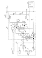
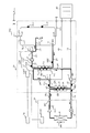
- FIG. 1 is a schematic configuration diagram of a hot water supply apparatus 100 according to Embodiment 1.
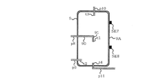
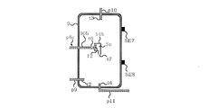
- FIG. 2 is a configuration explanatory view of a hot water storage tank 9 of the hot water supply apparatus 100 according to Embodiment 1.
- FIG. 2 is a block diagram of a control function of hot water supply device 100 according to the first embodiment.
- FIG. 6 is an operation explanatory view of first and second boiling operations of water heating apparatus 100 according to the first embodiment.
- 5 is a control flowchart of the hot water supply apparatus 100 according to the first embodiment. It is explanatory drawing of the temperature of the hot water storage tank 9 at the time of the start of 1st boiling operation, and the temperature of the hot water storage tank 9 at the time of start of 2nd boiling operation.
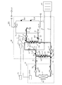
- FIG. 6 is a schematic configuration diagram of a modification of hot water supply device 100 according to Embodiment 1. It is a block diagram of a control function of a modification of hot water supply apparatus 100 concerning Embodiment 1.
- FIG. 8 is a schematic configuration diagram of a hot water supply apparatus 200 according to Embodiment 2.
- FIG. 13 is a block diagram of a control function of water heating apparatus 200 according to Embodiment 2.
- FIG. 14 is an operation explanatory view of a first boiling operation of the hot water supply apparatus 200 according to Embodiment 2.
- FIG. 16 is an operation explanatory view of a second boiling operation of the hot water supply apparatus 200 according to Embodiment 2.
- FIG. 10 is a schematic configuration diagram of a hot water supply apparatus 300 according to Embodiment 3.
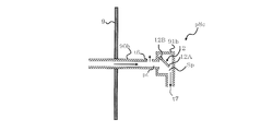
- FIG. 18 is an explanatory diagram of a hot water storage tank 9 and an inflow piping p8c of the hot water supply apparatus 300 according to Embodiment 3. It is an enlarged view of the inflow piping p8c shown in FIG.
- the opening-and-closing mechanism part 12 in the 1st boiling operation is shown.
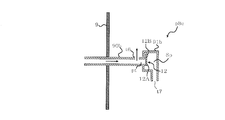
- the opening / closing mechanism part 12 in the 2nd boiling operation is shown.
- Embodiment 1 Hereinafter, Embodiment 1 will be described with reference to the drawings.
- size of each structural member may differ from an actual thing.
- the form of the component shown in the full text of the specification is just an example, and is not limited to these descriptions.
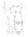
- FIG. 1 is a schematic block diagram of a hot water supply apparatus 100 according to the first embodiment.
- the water heating apparatus 100 includes a heat pump unit 20, a tank unit 30, and a remote controller 70 that outputs a control command to the tank unit 30.
- the heat pump unit 20 and the tank unit 30 are connected via the gas pipe P1 and the liquid pipe P2.
- the tank unit 30 is connected to the heating device 40 via the pipe p1 and the pipe p5.
- An example of the heating device 40 is a floor heating device and a radiator of an indoor unit of an air conditioner.
- the heat pump unit 20 includes a compressor 1 that compresses a refrigerant, a throttling device 3 that decompresses the refrigerant, a heat exchanger 4 that functions as an evaporator, and a blower 4A that supplies air to the heat exchanger 4 .
- the heat pump unit 20 also includes a pressure sensor SE1 that detects the pressure of the refrigerant discharged from the compressor 1, and a control device Cnt2 that controls the compressor 1, the expansion device 3, and the blower 4A.
- the compressor 1 and the first pump 8 and the second pump 5 described later each include an inverter.
- the throttling device 3 is an expansion valve.
- the tank unit 30 includes a heat medium circuit C including a primary circuit C1 and a secondary circuit C2 that receives heat from the primary circuit C1.
- the heat medium of the primary circuit C1 is water or brine.
- the heat medium of the secondary circuit C2 is water.
- the heat medium of the primary circuit C1 corresponds to the first heat medium, and the heat medium of the secondary circuit C2 corresponds to the second heat medium.
- the tank unit 30 further includes a hot water storage tank 9 for storing a heat medium, and a first pump 8 for transporting the heat medium to the hot water storage tank 9.
- the tank unit 30 includes a heating heat exchanger Hx that supplies the heat of the refrigerant generated by the heat pump unit 20 to the heat medium of the hot water storage tank 9.
- the heating heat exchanger Hx includes a first heat exchanger 2 and a second heat exchanger 7.
- the tank unit 30 includes a first heat exchanger 2 which exchanges heat between the refrigerant and the heat medium, and a second pump 5 which conveys the heat medium to the first heat exchanger 2.
- the first heat exchanger 2 includes a first heat medium flow path 2A for flowing a heat medium, and a refrigerant flow path 2B for flowing a refrigerant.
- the water heating apparatus 100 includes a refrigerant circuit RC provided with a compressor 1, a first heat exchanger 2, a throttling device 3 and a heat exchanger 4.
- a carbon dioxide refrigerant, an HFC refrigerant, an HC refrigerant, or an HFO refrigerant can be employed.
- the tank unit 30 has a flow path switching device 6 that switches the flow path of the heat medium of the primary circuit C1, and a second heat exchanger that exchanges heat between the heat medium of the primary circuit C1 and the heat medium of the secondary circuit C2. It is equipped with seven.
- the flow path switching device 6 includes an inlet a connected to the first heat medium flow path 2A, an outlet b connected to the second heat exchanger 7, and an outlet c connected to the heating device 40. ing.
- the second heat exchanger 7 causes the heat medium of the primary circuit C1 to flow, and the second heat medium channel 7B connected to the outlet b and the third heat medium flow to cause the heat medium of the secondary circuit C2 to flow. And the road 7A.
- the primary circuit C1 includes a pipe p1 for flowing the heat medium flowing out of the heating device 40, a pipe p2 connected to the discharge part of the second pump 5, and a pipe p3 connected to the first heat medium flow path 2A. And a pipe p4 connected to the flow path switching device 6.
- the primary circuit C1 also includes a pipe p5 through which the heat medium flowing into the heating device 40 flows, and a pipe p6 which returns the heat medium having passed through the second heat exchanger 7 to the suction portion of the second pump 5 ing.
- the secondary circuit C ⁇ b> 2 includes a pipe p ⁇ b> 7 connected to the suction portion of the first pump 8.
- the secondary circuit C2 is connected to the hot water storage tank 9, and is connected to the inflow piping p8 for flowing the heat medium from the discharge part of the first pump 8 to the hot water storage tank 9, and connected to the hot water storage tank 9. And an outflow pipe p9 for flowing the heat medium to the third heat medium flow channel 7A of the heat exchanger 7 of FIG.
- the heat medium circuit C has the following configuration in addition to the primary circuit C1 and the secondary circuit C2.
- the heat medium circuit C includes a hot water discharge pipe p10 connected to the hot water storage tank 9 and supplying the heat medium to the utilization unit U of the heat medium, and a pipe p11 connected to the hot water storage tank 9 and connected to a water pipe, for example There is.
- the user unit U is a bathroom shower, a bathroom faucet, and a kitchen faucet.
- the heat medium of the hot water storage tank 9 is consumed, the heat medium is supplied from the pipe p11. For this reason, the heat medium of the hot water storage tank 9 is normally full of water.
- the tank unit 30 detects the temperature of the heat medium of the pipe p3, the temperature sensor SE2 of the heat medium of the pipe p2, and the temperature sensor SE2 of the heat medium of the pipe p2. And a temperature sensor SE4.
- the tank unit 30 includes a temperature sensor SE5 that detects the temperature of the heat medium of the pipe p7, and a temperature sensor SE6 that detects the temperature of the heat medium of the outflow pipe p9.
- the tank unit 30 is provided in the hot water storage tank 9, and is provided with a lower temperature sensor SE8 for detecting the lower temperature of the heat medium stored in the hot water storage tank 9, and the thermal storage tank provided with the hot water storage tank 9 and stored in the hot water storage tank 9.
- an upper temperature sensor SE7 for detecting the upper temperature of the medium.
- the upper temperature sensor SE7 is provided above the lower temperature sensor SE8.
- the tank unit 30 further includes a control device Cnt1 that controls the first pump 8, the second pump 5, and the flow path switching device 6.
- the controller Cnt1 communicates
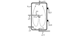
- FIG. 2 is a configuration explanatory view of the hot water storage tank 9 of the hot water supply apparatus 100 according to the first embodiment.
- the hot water discharge pipe p10 includes a first opening t3 provided in the hot water storage tank 9.
- the inflow piping p ⁇ b> 8 includes a second opening t ⁇ b> 1 provided in the hot water storage tank 9.
- the second opening t1 is provided below the first opening t3 of the tapping pipe p10.
- the inflow piping p8 includes a horizontal portion 90 extending in parallel to the horizontal surface, and a vertical portion 91 extending in parallel to the vertical direction. The upper end of the vertical portion 91 is connected to the end of the horizontal portion 90.
- a second opening t1 is provided at the lower end of the vertical portion 91.
- the outflow pipe p9 includes a third opening t2 provided in the hot water storage tank 9.
- the third opening t2 is provided below the second opening t1 of the inflow piping p8. That is, in the space for storing the heat medium in the hot water storage tank 9, a first opening t3, a second opening t1, and a third opening t2 are provided in order from the top.
- the upper temperature sensor SE7 is provided below the first opening t3 of the hot water discharge piping p10 and above the second opening t1 of the inflow piping p8.
- the lower temperature sensor SE8 is provided below the second opening t1 of the inflow piping p8 and above the third opening t2 of the outflow piping p9.
- the upper temperature sensor SE7 and the lower temperature sensor SE8 are fixed to the side surface 9A of the hot water storage tank 9.
- the pipe p11 includes an opening t4 provided in the hot water storage tank 9. The opening t4 is provided below the third opening t2.
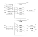
- FIG. 3 is a block diagram of a control function of hot water supply apparatus 100 according to the first embodiment.
- the control device Cnt1 includes an acquisition unit 50A that acquires data from various sensors, an operation unit 50B that performs an operation, a control unit 50C that controls an actuator, and a storage unit 50D that stores data.
- the acquisition unit 50A acquires a control instruction of the remote controller 70, a detection temperature of the temperature sensor SE3, a detection temperature of the temperature sensor SE4, a detection temperature of the temperature sensor SE5, and a detection temperature of the temperature sensor SE6.
- the acquiring unit 50A acquires the detected temperature of the upper temperature sensor SE7 and the detected temperature of the lower temperature sensor SE8.
- the calculation unit 50B has a first function of comparing the temperature detected by the upper temperature sensor SE7 with a predetermined threshold value.
- the calculation unit 50B also has a second function of comparing the temperature detected by the lower temperature sensor SE8 with a predetermined threshold value.
- Arithmetic unit 50B determines whether or not the boiling operation is to be performed by performing the first function and the second function.
- the control unit 50C controls the first pump 8, the second pump 5, and the flow path switching device 6.
- the control unit 50C can obtain the control target value of the first pump 8 and the control target value of the second pump 5 from the storage unit 50D.
- the control device Cnt2 includes an acquisition unit 60A that acquires data from various sensors, an operation unit 60B that performs an operation, a control unit 60C that controls an actuator, and a storage unit 60D that stores data.
- the acquisition unit 60A acquires the detected pressure of the pressure sensor SE1 and the detected temperature of the temperature sensor SE2.
- the calculation unit 60B has a function of calculating a control target value of the compressor 1. Furthermore, the calculation unit 60B has a function of calculating the degree of subcooling of the first heat exchanger 2.
- the calculation unit 60B calculates the condensation temperature of the refrigerant based on the pressure detected by the pressure sensor SE1.
- the calculation unit 60B calculates the degree of subcooling of the first heat exchanger 2 from the difference between the calculated condensation temperature and the temperature sensor SE2. Moreover, the calculating part 60B has a function which calculates the average heating capability which has determined the control target value of the compressor 1. The average heating capacity will be described later with reference to FIG.
- the controller 60C controls the compressor 1, the expansion device 3 and the blower 4A.
- the control unit 60C can obtain the control target value of the compressor 1 and the control target value of the expansion device 3 from the calculation unit 60B.
- control device Cnt1 and the control device Cnt2 are collectively referred to as a control device.
- Each functional unit included in the control device is configured by dedicated hardware or an MPU (Micro Processing Unit) that executes a program stored in a memory.
- the control device is dedicated hardware, the control device is, for example, a single circuit, a composite circuit, an application specific integrated circuit (ASIC), a field-programmable gate array (FPGA), or a combination thereof.
- ASIC application specific integrated circuit
- FPGA field-programmable gate array
- Each of the functional units realized by the control device may be realized by individual hardware, or each functional unit may be realized by one hardware.
- each function executed by the control device is realized by software, firmware, or a combination of software and firmware. Software and firmware are described as programs and stored in memory.
- the MPU implements each function of the control device by reading and executing the program stored in the memory.
- the memory is, for example, a nonvolatile or volatile semiconductor memory such as a RAM, a ROM, a flash memory, an EPROM, and an EEPROM.
- FIG. 4 is an operation explanatory view of the first boiling operation and the second boiling operation of the hot water supply apparatus 100 according to the first embodiment.
- the hot water supply apparatus 100 executes a first boiling operation which is performed at, for example, late night when the hot water supply load is small, and a second boiling operation which is performed when, for example, the evening and the night when the hot water supply load is large.
- a first boiling operation which is performed at, for example, late night when the hot water supply load is small
- a second boiling operation which is performed when, for example, the evening and the night when the hot water supply load is large.
- the order in which the refrigerant flows in each configuration is the same, and the order in which the heat medium flows in each configuration is also the same.
- the refrigerant will be described.
- the refrigerant is compressed by the compressor 1 and then discharged from the compressor 1.
- the refrigerant discharged from the compressor 1 flows into the refrigerant flow path 2B, and heats the heat medium of the first heat medium flow path 2A.
- the refrigerant is liquefied in the process of passing through the refrigerant flow path 2B.
- the refrigerant flowing out of the first heat medium channel 2A is decompressed by the expansion device 3.
- the refrigerant decompressed by the expansion device 3 is in a gas-liquid two-phase state.
- the refrigerant flowing out of the expansion device 3 flows into the heat exchanger 4 and absorbs heat from the air.
- the refrigerant is gasified in the process of passing through the heat exchanger 4.
- the heat medium is pressurized by the second pump 5 and discharged from the second pump 5.
- the heat medium discharged from the second pump 5 flows into the first heat medium channel 2A through the pipe p2, and is heated by the refrigerant.
- the heat medium having flowed out of the first heat medium channel 2A flows into the flow path switching device 6 through the pipe p3.
- the heat medium flows from the inlet a to the outlet b.
- the exit c is closed. Therefore, the heat medium does not flow from the inlet a to the outlet c.
- the heat medium having flowed out from the outlet b flows into the second heat medium channel 7B through the pipe p4, and heats the heat medium of the third heat medium channel 7A of the primary circuit C1.
- the heat medium having flowed out of the second heat medium channel 7B returns to the second pump 5 through the pipe p6 and the pipe p1.
- the heat medium is pressurized by the first pump 8 and discharged from the first pump 8.
- the heat medium discharged from the first pump 8 flows into the hot water storage tank 9 through the inflow pipe p8.
- the heat medium of the hot water storage tank 9 flows into the third heat medium channel 7A through the outflow pipe p9, and is heated by the heat medium of the second heat medium channel 7B of the primary circuit C1.
- the heat medium flowing out of the third heat medium channel 7A returns to the first pump 8 through the pipe p7.
- FIG. 5 is a control flowchart of water heating apparatus 100 according to the first embodiment.
- FIG. 6 is an explanatory view of the temperature of the hot water storage tank 9 at the start of the first boiling operation and the temperature of the hot water storage tank 9 at the start of the second boiling operation.
- the controller Cnt1 starts the control flow according to the first boiling operation and the second boiling operation (step S0).
- the present control flow starts every predetermined time.
- the controller Cnt1 determines whether the temperature detected by the upper temperature sensor SE7 is less than the first boiling temperature Tus1 (step S101).
- the first boiling temperature Tus1 is 40 ° C., for example.
- the control device Cnt1 executes the first boiling operation (step S102). That is, the control device Cnt1 starts the operation of the first pump 8 and the second pump 5, and the control device Cnt1 outputs an instruction to start the operation of the actuator such as the compressor 1 to the control device Cnt2.
- the control device Cnt2 that has received the instruction from the control device Cnt1 starts the operation of the compressor 1 and the blower 4A.
- the control device Cnt1 determines whether the temperature detected by the lower temperature sensor SE8 is higher than the first stop temperature Tde1 (step S103).
- the first stop temperature Tde1 is 55 ° C., for example.
- the controller Cnt1 stops the first pump 8 and the second pump 5, and the controller Cnt2 controls the compressor 1 and the blower 4A. Are stopped (step S108).
- step S104 the controller Cnt1 determines whether the temperature detected by the upper temperature sensor SE7 is less than the second boiling temperature Tus2.
- the second boiling temperature Tus2 is higher than the first boiling temperature Tus1, and is 50 ° C., for example. If the temperature detected by the upper temperature sensor SE7 is less than the second boiling temperature Tus2, the controller Cnt1 determines whether the temperature detected by the lower temperature sensor SE8 is less than the third boiling temperature Tds2. (Step S105).
- FIG. 6 the second boiling temperature Tus2 is higher than the first boiling temperature Tus1, and is 50 ° C., for example.
- the third boiling temperature Tds2 is lower than the first boiling temperature Tus1 and the second boiling temperature Tus2, for example, 15 ° C. If the temperature detected by the lower temperature sensor SE8 is less than the third boiling temperature Tds2, the control device Cnt1 executes the second boiling operation (step S106). That is, the control device Cnt1 starts the operation of the first pump 8 and the second pump 5, and the control device Cnt1 outputs an instruction to start the operation of the actuator such as the compressor 1 to the control device Cnt2.
- the control device Cnt2 that has received the instruction from the control device Cnt1 starts the operation of the compressor 1 and the blower 4A.
- the control device Cnt1 determines whether the temperature detected by the upper temperature sensor SE7 is higher than the second stop temperature Tue2 (step S107).
- the second stop temperature Tue2 is higher than the first stop temperature Tde1, for example, 60 ° C.
- the controller Cnt1 stops the first pump 8 and the second pump 5, and the controller Cnt2 controls the compressor 1 and the blower 4A. Are stopped (step S108).
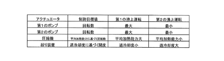
- FIG. 7 is an explanatory view of a control target value of the actuator in the first boiling operation and a control target value of the actuator in the second boiling operation.
- the control target value of the actuator in the first boiling operation is defined as follows. That is, the control target value of the first pump 8 is the pump rotational speed x1, the control target value of the second pump 5 is the pump rotational speed x2, and the control target value of the compressor 1 is the compressor rotational speed x3.
- the control target value of the device 3 is set to the opening degree x4.
- the pump rotational speed x1 corresponds to the first pump rotational speed.
- the pump rotational speed x2 corresponds to the third pump rotational speed.
- the pump rotational speed x1 and the pump rotational speed x2 are predetermined rotational speeds.
- the pump rotational speed x1 and the pump rotational speed x2 are stored in the storage unit 50D.
- the pump rotational speed x1 is, for example, the maximum rotational speed of the first pump 8.
- the pump rotational speed x 2 is, for example, the maximum rotational speed of the second pump 5.
- a first average heating capacity is a value obtained by dividing the amount of heat increase of the hot water storage tank 9 from the start to the end of the first boiling operation by the time from the start to the end of the first boiling operation.
- the second average is a value obtained by dividing the amount of heat increase of the hot water storage tank 9 from the start to the end of the second boiling operation by the time from the start to the end of the second boiling operation. It is defined as heating capacity.
- the compressor rotational speed x3 is the first average heating than the second average heating capacity. It is predetermined that the ability is greater.
- the temperature conditions are, for example, the outside air temperature and the tap water temperature.
- the degree of subcooling of the first heat exchanger 2 in the first boiling operation is a first degree of subcooling
- the degree of subcooling of the first heat exchanger 2 in the second boiling operation is a second Degree of supercooling.
- the calculation unit 60B calculates the first degree of subcooling and the second degree of subcooling.
- the storage unit 60D stores a first target degree of supercooling in the first boiling operation and a second target degree of supercooling in the second boiling operation.
- the first target degree of supercooling is smaller than the second target degree of supercooling.
- the opening degree x4 is set such that the first degree of subcooling is smaller than the second degree of subcooling.
- the control target value of the actuator in the second boiling operation can be described in the same manner as the control target value of the actuator in the first boiling operation, as described above.
- the control target value of the actuator in the second boiling operation describes a portion different from the control target value of the actuator in the first boiling operation.
- the control target value of the actuator in the second boiling operation is defined as follows.
- a control target value of the first pump 8 is a pump rotational speed y1
- a control target value of the second pump 5 is a pump rotational speed y2
- a control target value of the compressor 1 is a compressor rotational speed y3.
- the control target value of is set to the opening degree y4.
- the pump rotational speed y1 corresponds to the second pump rotational speed.
- the pump rotational speed y2 corresponds to the fourth pump rotational speed.
- the pump rotational speed y1 is, for example, the minimum rotational speed of the first pump 8.
- the pump rotational speed x 2 is, for example, the minimum rotational speed of the second pump 5.
- the compressor rotational speed y3 is set such that the first average heating capacity is larger than the second average heating capacity.
- the opening degree y4 is set so that the first degree of subcooling is smaller than the second degree of subcooling.
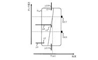
- FIG. 8 shows the temperature distribution of the hot water storage tank 9 at the start of the first boiling operation.
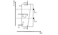
- FIG. 9 shows the temperature distribution of the hot water storage tank 9 when the temperature of the hot water storage tank 9 is raised by the first boiling operation.
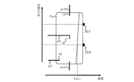
- FIG. 10 shows the temperature distribution of the hot water storage tank 9 at the end of the first boiling operation.
- FIG. 8 when the temperature of the heat medium of the hot water storage tank 9 is lowered due to the heat release of the hot water storage tank 9, the temperature of the heat medium of the hot water storage tank 9 rises gently from the lower side to the upper side of the hot water storage tank 9. doing. That is, the difference between the temperature of the heat medium on the upper side of the hot water storage tank 9 and the temperature of the heat medium on the lower side of the hot water storage tank 9 is small.
- the detected temperature of the upper temperature sensor SE7 is lower than the first boiling temperature Tus1. For this reason, the hot water supply apparatus 100 executes the first boiling operation.
- the heated heat medium flows into the hot water storage tank 9 from the inflow pipe p8.
- the heated heat medium spreads over the entire hot water storage tank 9 as described later with reference to FIG.
- the temperature of the entire heat medium of the hot water storage tank 9 rises.
- the detected temperature of the lower temperature sensor SE8 exceeds the first stop temperature Tde1. Therefore, the hot water supply apparatus 100 ends the first boiling operation.
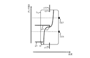
- FIG. 11 shows the temperature distribution of the hot water storage tank 9 at the start of the second boiling operation.
- FIG. 12 shows the temperature distribution of the hot water storage tank 9 when the temperature of the hot water storage tank 9 is raised by the second boiling operation.
- FIG. 13 shows the temperature distribution of the hot water storage tank 9 at the end of the second boiling operation.
- FIG. 11 when the temperature of the heat medium of the hot water storage tank 9 is lowered due to the increase of the usage amount of hot water supply, the temperature of the heat medium of the hot water storage tank 9 rapidly increases from the lower side to the upper side of the hot water storage tank 9 It is rising. That is, the difference between the temperature of the heat medium on the upper side of the hot water storage tank 9 and the temperature of the heat medium on the lower side of the hot water storage tank 9 is large.
- a place where the temperature of the heat medium rises rapidly corresponds to the temperature stratification of the hot water storage tank 9.
- the detected temperature of the upper temperature sensor SE7 is less than the second boiling temperature Tus2, and the detected temperature of the lower temperature sensor SE8 is less than the third boiling temperature Tds2. Therefore, the hot water supply apparatus 100 executes the second boiling operation.
- the heated heat medium is mainly supplied to the upper portion of the hot water storage tank 9 as described later with reference to FIG.
- the temperature of the heat medium in the upper part of the hot water storage tank 9 rises.
- the detected temperature of the upper temperature sensor SE7 exceeds the second stop temperature Tue2. Therefore, the hot water supply apparatus 100 ends the second boiling operation.
- FIG. 14 shows the flow of the heat medium of the hot water storage tank 9 in the first boiling operation. Since the rotation speed of the first pump 8 in the first boiling operation is higher than the rotation speed of the first pump 8 in the second boiling operation, from the second opening t1 in the first boiling operation The flow velocity of the heat medium flowing into the hot water storage tank 9 is high. Therefore, the heat medium flowing into the hot water storage tank 9 from the second opening t1 flows to the lower part of the hot water storage tank 9, and then flows to the upper part of the hot water storage tank 9 by buoyancy. As described above, in the first boiling operation, the heated heat medium flows in the entire hot water storage tank 9, and thus the heated heat medium spreads in the entire water storage tank 9. As a result, the temperature of the entire heat medium of the hot water storage tank 9 rises.
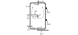
- FIG. 15 shows the flow of the heat medium of the hot water storage tank 9 in the second boiling operation.
- the rotation speed of the second pump 5 in the second boiling operation is lower than the rotation speed of the second pump 5 in the first boiling operation, and the temperature at the outlet of the first heat medium flow path 2A rises It's easy to do.
- a high temperature heat medium is supplied to the second heat medium channel 7B. Therefore, the number of rotations of the first pump 8 in the second boiling operation is lower than the number of rotations of the first pump 8 in the first boiling operation, and a high temperature is applied to the second heat medium passage 7B.
- the temperature of the outlet of the third heat medium channel 7A is also likely to rise.
- the buoyancy acts more greatly. Furthermore, the rotation speed of the first pump 8 in the second boiling operation is lower than the rotation speed of the first pump 8 in the first boiling operation, and the second opening in the second boiling operation The flow velocity of the heat medium flowing into the hot water storage tank 9 from t1 is low.
- the heat transfer medium flowing into the hot water storage tank 9 from the second opening t1 in the second boiling operation has a greater buoyancy and has a lower flow velocity, so the second heating operation from the second opening t1 in the second boiling operation
- the heat medium flowing into the hot water storage tank 9 does not flow to the lower part of the hot water storage tank 9 but flows to the upper part of the hot water storage tank 9.
- the temperature of the heat medium in the upper part of the hot water storage tank 9 rises. That is, the temperature of the heat medium at the upper portion of the hot water storage tank 9 in the second boiling operation tends to be higher than the temperature of the heat medium at the upper portion of the hot water storage tank 9 in the first boiling operation.
- the heat medium whose temperature rise in the lower portion of the hot water storage tank 9 is suppressed in the second boiling operation flows out of the hot water storage tank 9 from the outflow pipe p9.
- the water heater 100 includes an upper temperature sensor SE7 and a lower temperature sensor SE8. Therefore, in the control device Cnt1, the temperature of the heat medium of the hot water storage tank 9 is decreased due to the first temperature distribution in which the temperature of the heat medium of the hot water storage tank 9 is decreased due to heat release of the hot water storage tank 9 The second temperature distribution can be determined more accurately.
- the control device Cnt1 can more accurately determine the first temperature distribution and the second temperature distribution.
- the control device Cnt1 can more accurately determine the first temperature distribution and the second temperature distribution. Therefore, when the temperature of the heat medium of the hot water storage tank 9 is lowered due to the increase of the usage amount of the hot water supply, the control device Cnt1 can execute the second boiling operation more reliably. That is, in the situation where the end of the day approaches, such as evening and night, when the hot water supply apparatus 100 boils the entire heat medium of the hot water storage tank 9, the possibility of generating hot water which is not used increases. However, since the control device Cnt1 can more reliably execute the second boiling operation, it is possible to suppress the generation of hot water that is not used. That is, since the hot water supply apparatus 100 can suppress the generation of the hot water that is not used, the power consumption can be suppressed.
- the control device Cnt1 can perform the first boiling operation more reliably. That is, although the total heat quantity of the hot water storage tank 9 is greatly reduced as in the middle of the night, the hot water supply apparatus 100 can boil the whole heat medium while the hot water supply load is small.
- the control device Cnt1 uses the second boiling temperature Tus2 higher than the first boiling temperature Tus1 for determining the start of the second boiling operation. Therefore, even if the temperature of the heat medium at the upper part of the hot water storage tank 9 is high, that is, even when a certain amount of high temperature heat medium can be secured in the hot water storage tank 9, the controller Cnt1 performs the second boiling operation Can be performed. Accordingly, it is possible to avoid that the hot water supply device 100 can not supply the high-temperature heat medium to the utilization unit U in a situation where the usage amount of the heat medium of the hot water storage tank 9 is increased as in the evening and night.
- the controller Cnt1 stops the first pump 8 when the temperature detected by the lower temperature sensor SE8 becomes higher than the first stop temperature Tde1 while performing the first boiling operation. That is, the control device Cnt1 uses the lower temperature sensor SE8 instead of the upper temperature sensor SE7 to determine the end of the first boiling operation.
- the temperature of the heat medium in the lower part of the hot water storage tank 9 is lower than the temperature of the heat medium in the upper part of the hot water storage tank 9. For this reason, when the control device Cnt1 uses the lower temperature sensor SE8 to determine the end of the first boiling operation, the hot water supply device 100 can more surely boil the whole heat medium of the hot water storage tank 9.
- the controller Cnt1 stops the first pump 8 when the temperature detected by the upper temperature sensor SE7 becomes higher than the second stop temperature Tue2 while performing the second boiling operation. That is, the control device Cnt1 uses the upper temperature sensor SE7 instead of the lower temperature sensor SE8 to determine the end of the first heating operation.
- the heated heat medium flows to the upper part of the hot water storage tank 9. Therefore, when the control device Cnt1 uses the upper temperature sensor SE7 to determine the end of the second boiling operation, the hot water supply device 100 can more surely boil the heat medium in the upper portion of the hot water storage tank 9.
- the second stop temperature Tue2 is higher than the first stop temperature Tde1.
- the temperature of the heat medium at the upper portion of the hot water storage tank 9 in the second boiling operation is higher than the temperature of the heat medium at the upper portion of the hot water storage tank 9 in the first boiling operation. It's easy to do. Therefore, even if the second stop temperature Tue2 is equal to or lower than the first stop temperature Tde1, the control device Cnt1 performs the second boiling operation even though the amount of the heat medium boiled is not very large. The possibility of ending is increased. For this reason, since 2nd stop temperature Tue2 is higher than 1st stop temperature Tde1, the hot-water supply apparatus 100 can ensure the heat medium boiled up in the 2nd boiling operation.
- the control device Cnt1 sets not only the first pump 8 but also the second pump 5 to a maximum number of revolutions. That is, the rotation speed of the first pump 8 in the first boiling operation is higher than the rotation speed of the first pump 8 in the second boiling operation, and the second pump in the first boiling operation The rotational speed of 5 is higher than the rotational speed of the second pump 5 in the second boiling operation.
- the control device Cnt1 increases the flow rate of the heat medium of the primary circuit C1 as the flow rate of the heat medium of the secondary circuit C2 increases. Thereby, the heat exchange efficiency in the first heat exchanger 2 and the heat exchange efficiency in the first heat exchanger 2 are improved.
- the upper temperature sensor SE7 is provided below the first opening t3 of the hot water discharge piping p10 and above the second opening t1 of the inflow piping p8.
- the lower temperature sensor SE8 is provided below the second opening t1 of the inflow piping p8 and above the third opening t2 of the outflow piping p9. Therefore, the upper temperature sensor SE7 can be easily positioned above the temperature stratification of the hot water storage tank 9, and the lower temperature sensor SE8 can be easily positioned below the temperature stratification of the hot water storage tank 9. Therefore, the control device Cnt1 can more accurately determine the first temperature distribution and the second temperature distribution.
- the controller Cnt1 controls the compressor 1 such that the second average heating capacity is smaller than the first average heating capacity.
- the rotational speed of the second pump 5 is suppressed, and is, for example, the minimum rotational speed. That is, in the second boiling operation, the flow rate of the heat medium of the primary circuit C1 is suppressed.
- the control device Cnt1 suppresses the rotational speed of the compressor 1 in the second boiling operation, the hot water supply device 100 can prevent the discharge pressure of the compressor 1 from rising excessively.
- the control device Cnt1 controls the expansion device 3 so that the second degree of subcooling in the second boiling operation becomes larger than the first degree of subcooling in the first boiling operation. ing.
- the rotational speed of the second pump 5 is suppressed, and is, for example, the minimum rotational speed. Since the flow rate of the heat medium flowing into the first heat exchanger 2 is suppressed, the difference between the inlet temperature of the heat medium of the first heat exchanger 2 and the outlet temperature of the heat medium of the first heat exchanger 2 is There is a tendency to increase. Therefore, the control device Cnt1 increases the degree of subcooling of the first heat exchanger 2 in the second boiling operation.
- the outlet temperature of the refrigerant of the first heat exchanger 2 is further lowered. That is, the difference between the inlet temperature of the refrigerant of the first heat exchanger 2 and the outlet temperature of the refrigerant of the first heat exchanger 2 is increased. Thereby, the heat exchange efficiency between the refrigerant and the heat medium in the first heat exchanger 2 is improved.
- FIG. 16 is a schematic block diagram of a modification of the hot water supply apparatus 100 according to the first embodiment.
- FIG. 17 is a block diagram of control functions of a modification of hot water supply apparatus 100 according to the first embodiment.
- the heat medium circuit C of the tank unit 30 of the hot water supply apparatus 100 includes the primary circuit C1 and the secondary circuit C2.
- the heat medium circuit C3 of the tank unit 30 of the hot water supply apparatus 100B according to the modification does not include a plurality of circuits. That is, although the heat medium circuit C is provided with the first heat exchanger 2 and the first pump 8, the heat medium circuit C3 is provided with the second pump 5, the flow path switching device 6, and the second The heat exchanger 7 is not provided. Even in the case of the hot water supply apparatus 100B, the same operation and effect as the hot water supply apparatus 100 according to the first embodiment can be obtained.
- FIG. 18 is a schematic block diagram of a hot water supply apparatus 200 according to the second embodiment.
- FIG. 19 is a block diagram of a control function of hot water supply device 200 according to the second embodiment.
- the secondary circuit C22 of the heat medium circuit C20 of the hot water supply apparatus 200 includes the flow path switching device 10 that switches the flow path of the heat medium. Further, the inflow piping p8b of the secondary circuit C22 is connected to the hot water storage tank 9, and is connected to a first inflow piping p82 through which the heat medium flows during the first boiling operation, and to the hot water storage tank 9; A second inflow pipe p83 through which the heat medium flows during the boiling operation is provided.
- the flow path switching device 10 has an inlet d connected to the discharge portion of the first pump 8, a first outlet f connected to the hot water storage tank 9 via the first inflow pipe p82, and a second inflow.
- the first inflow pipe p82 has the same configuration as the inflow pipe p8 described in the first embodiment.
- the second inflow piping p83 includes a fourth opening t5 provided in the hot water storage tank 9.
- the second opening t1 of the first inflow piping p82 is provided below the first opening t3 of the hot water discharge piping p10 and the fourth opening t5 of the second inflow piping p83.
- the third opening t2 of the outflow pipe p9 is provided below the second opening t1 of the first inflow pipe p82.
- the control unit 50C of the control device Cnt1 controls the flow path switching device 10 in addition to the first pump 8, the second pump 5 and the flow path switching device 6.
- FIG. 20 is an operation explanatory view of a first boiling operation of the hot water supply apparatus 200 according to the second embodiment.
- the control device Cnt1 opens the first outlet f of the flow channel switching device 10 and closes the second outlet e of the flow channel switching device 10. Therefore, the heat medium of the secondary circuit C22 flows into the hot water storage tank 9 via the first pump 8, the inlet d, the first outlet f, and the first inflow piping p82.
- FIG. 21 is an operation explanatory view of a second boiling operation of the hot water supply apparatus 200 according to the second embodiment.
- the controller Cnt1 closes the first outlet f of the flow channel switching device 10 and opens the second outlet e of the flow channel switching device 10. Therefore, the heat medium of the secondary circuit C22 flows into the hot water storage tank 9 through the first pump 8, the inlet d, the second outlet e, and the second inflow piping p83.
- the fourth opening t5 of the second inflow pipe p83 is provided above the second opening t1 of the first inflow pipe p82. That is, the fourth opening t5 of the second inflow pipe p83 is provided at the upper portion in the hot water storage tank 9.
- the fourth opening t5 of the second inflow pipe p83 is located above the temperature stratification. Therefore, in the second boiling operation, the heated heat medium flows from the fourth opening t5 into a portion of the hot water storage tank 9 above the temperature stratification. Then, the heat medium flowing into the upper part of the temperature stratification is suppressed from flowing downward because the temperature is high. Therefore, the hot water supply apparatus 200 can hold the thermal stratification of the hot water storage tank 9 more reliably. That is, the hot water supply apparatus 200 can suppress that the temperature of the heat medium used for hot water supply located above the temperature stratification falls.
- FIG. 22 is a schematic block diagram of a hot water supply apparatus 300 according to the third embodiment.
- FIG. 23 is an explanatory diagram of the hot water storage tank 9 and the inflow piping p8c of the hot water supply apparatus 300 according to the third embodiment.
- FIG. 24 is an enlarged view of the inflow piping p8c shown in FIG.
- the inflow piping p8c of the secondary circuit C32 of the heat medium circuit C30 of the hot water supply apparatus 300 is different in configuration from the inflow piping p8 of the secondary circuit C2 of the heat medium circuit C described in the first embodiment.
- the other configuration of heat medium circuit C30 is the same as the configuration of heat medium circuit C of water heating apparatus 100.
- the inflow piping p8c is provided in the first inlet t6 provided in the hot water storage tank 9 and in the hot water storage tank 9, and the heat medium is provided from the first inlet t6.
- a second inlet t7 provided on the downstream side in the flow direction.
- the first inlet t6 and the second inlet t7 are openings formed in the inlet pipe p8c.
- the opening area of the first inlet t6 is smaller than the opening area of the second inlet t7.
- the inflow piping p8c is provided downstream of the first inlet t6 in the flow direction of the heat medium and upstream of the second inlet t7 in the flow direction of the heat medium, and the inflow piping p8c
- An open / close mechanism unit 12 configured to open and close according to the flow rate of the flowing heat medium is provided.
- the inflow piping p8c is provided with a space Sp in which the opening / closing mechanism 12 is provided, and a flow path pt provided on the upstream side in the flow direction of the heat medium than the space Sp and opening / closing the opening / closing mechanism 12 It is formed.
- the space Sp is provided downstream of the first inlet t6 in the flow direction of the heat medium and upstream of the second inlet t7 in the flow direction of the heat medium.
- the opening and closing mechanism 12 includes an opening and closing part 12A for opening and closing the flow path pt, and a hinge part 12B for rotatably supporting the opening and closing part 12A.
- the opening / closing portion 12A closes the flow path pt by the weight of the opening / closing portion 12A.
- the inflow piping p8c is provided with a horizontal portion 90b extending in parallel to the horizontal surface and a vertical portion 91b extending in parallel in the vertical direction.
- the horizontal portion 90b is provided with a flow path pt and a first inlet t6.
- a space Sp, a second inlet t7, and an opening / closing mechanism 12 are provided in the vertical portion 91b.
- FIG. 25 shows the opening / closing mechanism 12 in the first boiling operation.
- the rotational speed of the first pump 8 in the first boiling operation is higher than the rotational speed of the first pump 8 in the second boiling operation.
- the pressure of the heat medium of the flow path pt in the first boiling operation becomes higher than the pressure of the heat medium of the flow path pt in the second boiling operation. Therefore, the heat medium of the flow path pt in the first boiling operation pushes up the open / close portion 12A.
- the heat medium of the flow path pt flows into the hot water storage tank 9 through the space Sp and the second inlet t7.
- a part of the heat medium flowing through the flow path pt flows into the hot water storage tank 9 from the first inlet t6.
- FIG. 26 shows the opening / closing mechanism 12 in the second boiling operation. Since the rotational speed of the first pump 8 in the second boiling operation is kept low, the heat medium of the flow path pt in the second boiling operation can not push up the opening / closing part 12A. That is, the flow path pt is closed to the opening / closing part 12A. Therefore, the heat medium of the flow path pt flows into the hot water storage tank 9 from the first inlet t6.
- the inflow pipe p8c is provided with an open / close mechanism unit 12 configured to open and close according to the flow rate of the heat medium.
- the flow rate of the heat medium in the inflow piping p8c in the first boiling operation is larger than the flow rate of the heat medium in the inflow piping p8c in the second boiling operation.
- the heat medium pushes up the opening and closing part 12A of the opening and closing mechanism part 12, and the flow path pt is opened. Then, a part of the heat medium flowing in the flow path pt flows downward from the second inlet t 7 and reaches the inside of the hot water storage tank 9.
- the heat medium flowing into the hot water storage tank 9 from the second inlet t7 flows to the lower portion in the hot water storage tank 9 and then flows to the upper portion in the hot water storage tank 9 by buoyancy.
- the temperature of the entire heat medium of the hot water storage tank 9 rises.
- the other part of the heat medium flowing in the flow path pt flows upward from the first inlet t6 and reaches the inside of the hot water storage tank 9.
- the other part of the heat medium flowing through the flow path pt contributes to the temperature rise of the heat medium in the upper part of the hot water storage tank 9.
- the heat medium can not push up the opening and closing part 12A of the opening and closing mechanism part 12, and the flow path pt is closed. Therefore, the heat medium flowing in the flow path pt flows upward from the first inlet t6 and reaches the inside of the hot water storage tank 9. Further, since the heat medium flowing in the flow path pt is heated by the second heat exchanger 7, a large buoyancy acts on the heat medium that has reached the hot water storage tank 9 from the flow path pt. As a result, the heat medium flowing into the hot water storage tank 9 from the first inlet t6 does not easily flow to the lower portion in the hot water storage tank 9, and flows to the upper portion in the hot water storage tank 9.
- the hot water supply apparatus 200 can hold the thermal stratification of the hot water storage tank 9 more reliably. That is, the hot water supply apparatus 300 can suppress that the temperature of the heat medium used for hot water supply located above the temperature stratification falls.
- the opening and closing mechanism 12 can open and close the flow path pt. Therefore, complication of the mechanism of the inflow piping p8c can be avoided.
- the action of the weight of the opening / closing portion 12A is used to open and close the flow path pt, but the present invention is not limited to this action.
- the elastic force of the spring and the magnetic force of the magnet may be used to open and close the flow path pt.
- the opening area of the second inlet t7 is larger than the opening area of the first inlet t6. Therefore, in the first boiling operation, the flow rate of the heat medium flowing into the hot water storage tank 9 from the second inlet t7 is the flow rate of the heat medium flowing into the hot water storage tank 9 from the first inlet t6. It will be more than the flow rate. Therefore, the heat medium flowing through the inflow piping p8c mainly flows into the hot water storage tank 9 from the second inlet t7. The heat medium flowing into the hot water storage tank 9 flows to the lower part of the hot water storage tank 9 and then flows to the upper part of the hot water storage tank 9 by buoyancy. That is, since the opening area of the second inlet t7 is larger than the opening area of the first inlet t6, the heat medium heated in the first boiling operation easily spreads over the entire hot water storage tank 9.
- the hot water supply device 300 can hold the thermal stratification of the hot water storage tank 9 more reliably. That is, the hot water supply apparatus 300 can suppress that the temperature of the heat medium used for hot water supply located above the temperature stratification falls.
Landscapes
- Engineering & Computer Science (AREA)
- Physics & Mathematics (AREA)
- Thermal Sciences (AREA)
- Chemical & Material Sciences (AREA)
- Combustion & Propulsion (AREA)
- Mechanical Engineering (AREA)
- General Engineering & Computer Science (AREA)
- Water Supply & Treatment (AREA)
- Heat-Pump Type And Storage Water Heaters (AREA)
Abstract
制御装置は、上部温度が第1の沸上温度よりも低い場合には、第1のポンプを第1のポンプ回転数で運転する第1の沸上運転を実行し、上部温度が第1の沸上温度より高い第2の沸上温度よりも低く、且つ、下部温度が第1の沸上温度より低い第3の沸上温度よりも低い場合には、第1のポンプを第1のポンプ回転数よりも低い第2のポンプ回転数で運転する第2の沸上運転を実行する。
Description
本発明は、給湯装置に関し、特に、貯湯タンクへ熱媒体を搬送するポンプを備えている給湯装置に関するものである。
従来の給湯装置には、熱媒体を貯留する貯湯タンクと、貯湯タンクに熱媒体を搬送するポンプと、貯湯タンクの温度を検出するサーミスタとを備えているものが提案されている(例えば、特許文献1参照)。ここで、貯湯タンクの放熱によって貯湯タンクの熱媒体の温度が低下したときにおける、貯湯タンク内の熱媒体の第1の温度分布は、給湯の利用量の増大によって貯湯タンク内の熱媒体の温度が低下したときにおける、貯湯タンク内の熱媒体の第2の温度分布とは異なっている。特許文献1の給湯装置の制御装置は、サーミスタの検出温度に基づいて、第1の温度分布と第2の温度分布とを判別している。また、特許文献1の給湯装置の制御装置は、温度分布の判別結果に応じて、沸上運転を実行するときのポンプの流量を変えている。これにより、特許文献1の給湯装置は貯湯タンク内の熱媒体を沸き上げるときの効率を向上させている。
特許文献1の給湯装置の制御装置は、サーミスタの検出温度の時間変化に基づいて貯湯タンクの熱媒体の温度分布を判別している。ここで、特許文献1の給湯装置の貯湯タンクのサーミスタは1つである。このため、判別結果が実際の温度分布からずれている可能性がある。つまり、特許文献1の給湯装置は、貯湯タンク内の熱媒体の温度分布の判別精度を確保し難い、という課題がある。
本発明は、上記のような課題を解決するためになされたもので、貯湯タンク内の熱媒体の温度分布をより高精度に判別することができる給湯装置を提供することを目的としている。
本発明に係る給湯装置は、熱媒体を貯留する貯湯タンクと、貯湯タンクに供給される熱媒体を加熱する加熱用熱交換器と、貯湯タンクに熱媒体を搬送する第1のポンプと、貯湯タンク、第1のポンプ、及び加熱用熱交換器が設けられている熱媒体回路と、貯湯タンクに設けられ、貯湯タンクに貯留されている熱媒体の下部温度を検出する下部温度センサと、貯湯タンクに設けられ、下部温度センサよりも上に設けられ、貯湯タンクに貯留されている熱媒体の上部温度を検出する上部温度センサと、第1のポンプを制御する制御装置と、を備え、制御装置は、上部温度が第1の沸上温度よりも低い場合には、第1のポンプを第1のポンプ回転数で運転する第1の沸上運転を実行し、上部温度が第1の沸上温度より高い第2の沸上温度よりも低く、且つ、下部温度が第1の沸上温度より低い第3の沸上温度よりも低い場合には、第1のポンプを第1のポンプ回転数よりも低い第2のポンプ回転数で運転する第2の沸上運転を実行する。
本発明に係る給湯装置によれば、上部温度センサ及び下部温度センサを備えているため、貯湯タンク内の熱媒体の温度分布をより高精度に判別することができる。
実施の形態1.
以下、図面を参照しながら実施の形態1について説明する。なお、以下の図面では各構成部材の大きさの関係が実際のものとは異なる場合がある。明細書全文に表わされている構成要素の形態は、あくまでも例示であって、これらの記載に限定されるものではない。
以下、図面を参照しながら実施の形態1について説明する。なお、以下の図面では各構成部材の大きさの関係が実際のものとは異なる場合がある。明細書全文に表わされている構成要素の形態は、あくまでも例示であって、これらの記載に限定されるものではない。
<実施の形態1の構成>
図1は、実施の形態1に係る給湯装置100の概要構成図である。図1に示すように、給湯装置100は、ヒートポンプユニット20と、タンクユニット30と、タンクユニット30に制御指令を出力するリモートコントローラ70とを備えている。ヒートポンプユニット20とタンクユニット30とはガス管P1及び液管P2を介して繋がっている。また、タンクユニット30は配管p1及び配管p5を介して暖房装置40に繋がっている。暖房装置40の一例は、床暖房機器、及び空気調和装置の室内機の放熱器である。
図1は、実施の形態1に係る給湯装置100の概要構成図である。図1に示すように、給湯装置100は、ヒートポンプユニット20と、タンクユニット30と、タンクユニット30に制御指令を出力するリモートコントローラ70とを備えている。ヒートポンプユニット20とタンクユニット30とはガス管P1及び液管P2を介して繋がっている。また、タンクユニット30は配管p1及び配管p5を介して暖房装置40に繋がっている。暖房装置40の一例は、床暖房機器、及び空気調和装置の室内機の放熱器である。
ヒートポンプユニット20は、冷媒を圧縮する圧縮機1と、冷媒を減圧する絞り装置3と、蒸発器として機能する熱交換器4と、熱交換器4に空気を供給する送風機4Aとを備えている。また、ヒートポンプユニット20は圧縮機1から吐出された冷媒の圧力を検出する圧力センサSE1と、圧縮機1、絞り装置3及び送風機4Aを制御する制御装置Cnt2とを備えている。なお、圧縮機1、後述する第1のポンプ8及び第2のポンプ5は、インバータを備える。また、絞り装置3は膨張弁である。
タンクユニット30は、1次回路C1、及び、1次回路C1から熱を受け取る2次回路C2を含む熱媒体回路Cを備えている。1次回路C1の熱媒体は、水又はブラインである。2次回路C2の熱媒体は、水である。1次回路C1の熱媒体が第1の熱媒体に対応し、2次回路C2の熱媒体が第2の熱媒体に対応する。また、タンクユニット30は、熱媒体を貯留する貯湯タンク9と、貯湯タンク9に熱媒体を搬送する第1のポンプ8とを備えている。更に、タンクユニット30は、ヒートポンプユニット20で生成した冷媒の熱を貯湯タンク9の熱媒体へ供給する加熱用熱交換器Hxを備えている。加熱用熱交換器Hxは第1の熱交換器2と第2の熱交換器7を含む。タンクユニット30は、冷媒と熱媒体とを熱交換する第1の熱交換器2と、第1の熱交換器2に熱媒体を搬送する第2のポンプ5とを備えている。第1の熱交換器2は、熱媒体を流す第1の熱媒体流路2A、及び冷媒を流す冷媒流路2Bを備えている。給湯装置100は、圧縮機1、第1の熱交換器2、絞り装置3及び熱交換器4が設けられている冷媒回路RCを備えている。冷媒回路RCには、二酸化炭素冷媒、HFC冷媒、HC冷媒、又はHFO冷媒を採用することができる。
タンクユニット30は、1次回路C1の熱媒体の流路を切り替える流路切替装置6と、1次回路C1の熱媒体と2次回路C2の熱媒体とを熱交換する第2の熱交換器7とを備えている。流路切替装置6は、第1の熱媒体流路2Aに繋がっている入口aと、第2の熱交換器7に繋がっている出口bと、暖房装置40に繋がっている出口cとを備えている。第2の熱交換器7は、1次回路C1の熱媒体を流し、出口bに繋がっている第2の熱媒体流路7Bと、2次回路C2の熱媒体を流す第3の熱媒体流路7Aとを備えている。
1次回路C1は、暖房装置40から流出する熱媒体を流す配管p1と、第2のポンプ5の吐出部に繋がっている配管p2と、第1の熱媒体流路2Aに繋がっている配管p3と、流路切替装置6に繋がっている配管p4とを備えている。また、1次回路C1は、暖房装置40へ流入する熱媒体が流れる配管p5と、第2の熱交換器7を通過した熱媒体を第2のポンプ5の吸入部へ戻す配管p6とを備えている。2次回路C2は、第1のポンプ8の吸入部に繋がっている配管p7を備えている。また、2次回路C2は、貯湯タンク9に接続され、第1のポンプ8の吐出部から貯湯タンク9へ熱媒体を流す流入配管p8と、貯湯タンク9に接続され、貯湯タンク9から第2の熱交換器7の第3の熱媒体流路7Aへ熱媒体を流す流出配管p9とを備えている。
熱媒体回路Cは、1次回路C1及び2次回路C2以外に次の構成を備える。熱媒体回路Cは、貯湯タンク9に接続され、熱媒体の利用部Uに熱媒体を供給する出湯配管p10と、貯湯タンク9に接続され、例えば水道管に繋がっている配管p11とを備えている。利用部Uは、浴室のシャワー、浴室の蛇口、及びキッチンの蛇口である。貯湯タンク9の熱媒体が消費されると、配管p11から熱媒体が供給される。このため、貯湯タンク9の熱媒体は、通常、満水状態になっている。
タンクユニット30は、第1の熱交換器2から流出した冷媒の温度を検出する温度センサSE2と、配管p2の熱媒体の温度を検出する温度センサSE3と、配管p3の熱媒体の温度を検出する温度センサSE4とを備えている。タンクユニット30は、配管p7の熱媒体の温度を検出する温度センサSE5と、流出配管p9の熱媒体の温度を検出する温度センサSE6とを備えている。タンクユニット30は、貯湯タンク9に設けられ、貯湯タンク9に貯留されている熱媒体の下部温度を検出する下部温度センサSE8と、貯湯タンク9に設けられ、貯湯タンク9に貯留されている熱媒体の上部温度を検出する上部温度センサSE7とを備えている。上部温度センサSE7は、下部温度センサSE8よりも上に設けられている。更に、タンクユニット30は、第1のポンプ8、第2のポンプ5、流路切替装置6を制御する制御装置Cnt1を備えている。制御装置Cnt1は制御装置Cnt2と通信する。
図2は、実施の形態1に係る給湯装置100の貯湯タンク9の構成説明図である。出湯配管p10は、貯湯タンク9内に設けられている第1の開口部t3を含む。流入配管p8は、貯湯タンク9内に設けられている第2の開口部t1を含む。第2の開口部t1は、出湯配管p10の第1の開口部t3よりも下に設けられている。流入配管p8は、水平面に平行に延びる水平部90と、鉛直方向に平行に延びる鉛直部91とを備えている。鉛直部91の上端部は水平部90の端部に繋がっている。また、鉛直部91の下端部には第2の開口部t1が設けられている。流出配管p9は、貯湯タンク9内に設けられている第3の開口部t2を含む。第3の開口部t2は、流入配管p8の第2の開口部t1よりも下に設けられている。つまり、貯湯タンク9内の熱媒体を貯留する空間には、上から順番に、第1の開口部t3、第2の開口部t1及び第3の開口部t2が設けられている。上部温度センサSE7は、出湯配管p10の第1の開口部t3よりも下であって流入配管p8の第2の開口部t1よりも上に設けられている。また、下部温度センサSE8は、流入配管p8の第2の開口部t1よりも下であって流出配管p9の第3の開口部t2よりも上に設けられている。上部温度センサSE7及び下部温度センサSE8は貯湯タンク9の側面部9Aに固定されている。配管p11は、貯湯タンク9内に設けられている開口部t4を含む。開口部t4は第3の開口部t2よりも下に設けられている。
図3は、実施の形態1に係る給湯装置100の制御機能のブロック図である。制御装置Cnt1は、各種センサからデータを取得する取得部50Aと、演算を行う演算部50Bと、アクチュエータを制御する制御部50Cと、データを記憶する記憶部50Dとを備えている。取得部50Aは、リモートコントローラ70の制御指示、温度センサSE3の検出温度、温度センサSE4の検出温度、温度センサSE5の検出温度及び温度センサSE6の検出温度を取得する。また、取得部50Aは、上部温度センサSE7の検出温度及び下部温度センサSE8の検出温度を取得する。演算部50Bは、上部温度センサSE7の検出温度と予め定められている閾値とを比較する第1の機能を有している。また、演算部50Bは、下部温度センサSE8の検出温度と予め定められている閾値とを比較する第2の機能を有している。演算部50Bは、第1の機能及び第2の機能を発揮することで、沸上運転を実行するか否かを判定する。制御部50Cは、第1のポンプ8、第2のポンプ5及び流路切替装置6を制御する。制御部50Cは、第1のポンプ8の制御目標値及び第2のポンプ5の制御目標値を、記憶部50Dから取得することができる。
制御装置Cnt2は、各種センサからデータを取得する取得部60Aと、演算を行う演算部60Bと、アクチュエータを制御する制御部60Cと、データを記憶する記憶部60Dとを備えている。取得部60Aは、圧力センサSE1の検出圧力、及び温度センサSE2の検出温度を取得する。演算部60Bは、圧縮機1の制御目標値を演算する機能を有している。更に、演算部60Bは、第1の熱交換器2の過冷却度を演算する機能を有している。演算部60Bは、圧力センサSE1の検出圧力に基づいて冷媒の凝縮温度を演算する。そして、演算部60Bは、演算した凝縮温度と、温度センサSE2との差から、第1の熱交換器2の過冷却度を演算する。また、演算部60Bは、圧縮機1の制御目標値を定めている平均加熱能力を演算する機能を有している。平均加熱能力については、後述の図7で説明する。制御部60Cは、圧縮機1、絞り装置3及び送風機4Aを制御する。制御部60Cは、圧縮機1の制御目標値及び絞り装置3の制御目標値を演算部60Bから取得することができる。
ここで、制御装置Cnt1及び制御装置Cnt2をここでは制御装置と総称する。制御装置に含まれる各機能部は、専用のハードウェア、又は、メモリに格納されるプログラムを実行するMPU(Micro Processing Unit)で構成される。制御装置が専用のハードウェアである場合、制御装置は、例えば、単一回路、複合回路、ASIC(application specific integrated circuit)、FPGA(field-programmable gate array)、またはこれらを組み合わせたものが該当する。制御装置が実現する各機能部のそれぞれを、個別のハードウェアで実現してもよいし、各機能部を一つのハードウェアで実現してもよい。制御装置がMPUの場合、制御装置が実行する各機能は、ソフトウェア、ファームウェア、またはソフトウェアとファームウェアとの組み合わせにより実現される。ソフトウェアやファームウェアはプログラムとして記述され、メモリに格納される。MPUは、メモリに格納されたプログラムを読み出して実行することにより、制御装置の各機能を実現する。メモリは、例えば、RAM、ROM、フラッシュメモリ、EPROM、EEPROM等の、不揮発性または揮発性の半導体メモリである。
<実施の形態1の動作>
図4は、実施の形態1に係る給湯装置100の第1の沸上運転及び第2の沸上運転の動作説明図である。給湯装置100は、給湯負荷が小さい例えば深夜に実行する第1の沸上運転と、給湯負荷が大きい例えば夕方及び夜に実行する第2の沸上運転とを実行する。図4に示すように、第1の沸上運転及び第2の沸上運転において、冷媒が各構成を流れる順番は同じであり、熱媒体が各構成を流れる順番も同じである。まず、冷媒の流れについて説明する。冷媒は圧縮機1で圧縮された後に圧縮機1から吐出される。圧縮機1から吐出された冷媒は、冷媒流路2Bに流入し、第1の熱媒体流路2Aの熱媒体を加熱する。冷媒は冷媒流路2Bを通過する過程で液化する。第1の熱媒体流路2Aから流出した冷媒は、絞り装置3で減圧される。絞り装置3で減圧された冷媒は気液二相状態になっている。絞り装置3から流出した冷媒は、熱交換器4に流入し、空気から吸熱する。冷媒は熱交換器4を通過する過程でガス化する。
図4は、実施の形態1に係る給湯装置100の第1の沸上運転及び第2の沸上運転の動作説明図である。給湯装置100は、給湯負荷が小さい例えば深夜に実行する第1の沸上運転と、給湯負荷が大きい例えば夕方及び夜に実行する第2の沸上運転とを実行する。図4に示すように、第1の沸上運転及び第2の沸上運転において、冷媒が各構成を流れる順番は同じであり、熱媒体が各構成を流れる順番も同じである。まず、冷媒の流れについて説明する。冷媒は圧縮機1で圧縮された後に圧縮機1から吐出される。圧縮機1から吐出された冷媒は、冷媒流路2Bに流入し、第1の熱媒体流路2Aの熱媒体を加熱する。冷媒は冷媒流路2Bを通過する過程で液化する。第1の熱媒体流路2Aから流出した冷媒は、絞り装置3で減圧される。絞り装置3で減圧された冷媒は気液二相状態になっている。絞り装置3から流出した冷媒は、熱交換器4に流入し、空気から吸熱する。冷媒は熱交換器4を通過する過程でガス化する。
次に、1次回路C1の熱媒体の流れを説明する。熱媒体は第2のポンプ5で加圧されて第2のポンプ5から吐出される。第2のポンプ5から吐出された熱媒体は、配管p2を介して第1の熱媒体流路2Aに流入し、冷媒に加熱される。第1の熱媒体流路2Aから流出した熱媒体は、配管p3を介して流路切替装置6に流入する。熱媒体は入口aから出口bへ流れる。なお、暖房装置40では暖房負荷が発生していないため、出口cは閉となっている。このため、熱媒体は入口aから出口cへ流れない。出口bから流出した熱媒体は配管p4を介して第2の熱媒体流路7Bに流入し、1次回路C1の第3の熱媒体流路7Aの熱媒体を加熱する。第2の熱媒体流路7Bから流出した熱媒体は配管p6及び配管p1を介して第2のポンプ5に戻る。
次に、2次回路C2の熱媒体の流れを説明する。熱媒体は第1のポンプ8で加圧されて第1のポンプ8から吐出される。第1のポンプ8から吐出された熱媒体は、流入配管p8を介して貯湯タンク9に流入する。貯湯タンク9の熱媒体は、流出配管p9を介して第3の熱媒体流路7Aに流入し、1次回路C1の第2の熱媒体流路7Bの熱媒体に加熱される。第3の熱媒体流路7Aから流出した熱媒体は配管p7を介して第1のポンプ8に戻る。
図5は、実施の形態1に係る給湯装置100の制御フローチャートである。図6は、第1の沸上運転の開始時の貯湯タンク9の温度及び第2の沸上運転の開始時の貯湯タンク9の温度の説明図である。制御装置Cnt1は第1の沸上運転及び第2の沸上運転に係る制御フローを開始する(ステップS0)。本制御フローは、予め定められた時間ごとに開始する。制御装置Cnt1は上部温度センサSE7の検出温度が第1の沸上温度Tus1未満であるか否かを判定する(ステップS101)。ここで、図6に示すように、第1の沸上温度Tus1は例えば40℃である。上部温度センサSE7の検出温度が第1の沸上温度Tus1未満である場合には、制御装置Cnt1は第1の沸上運転を実行する(ステップS102)。つまり、制御装置Cnt1は第1のポンプ8及び第2のポンプ5の運転を開始し、また、制御装置Cnt1は圧縮機1等のアクチュエータの運転を開始する指示を制御装置Cnt2に出力する。制御装置Cnt1から指示を取得した制御装置Cnt2は圧縮機1及び送風機4Aの運転を開始する。その後、制御装置Cnt1は下部温度センサSE8の検出温度が第1の停止温度Tde1よりも高いか否かを判定する(ステップS103)。ここで、図6に示すように、第1の停止温度Tde1は例えば55℃である。下部温度センサSE8の検出温度が第1の停止温度Tde1よりも高い場合には、制御装置Cnt1は第1のポンプ8及び第2のポンプ5を停止し、制御装置Cnt2は圧縮機1及び送風機4Aを停止する(ステップS108)。
ステップS101において上部温度センサSE7の検出温度が第1の沸上温度Tus1以上であった場合には、制御装置Cnt1はステップS104に進む。ステップS104において、制御装置Cnt1は、上部温度センサSE7の検出温度が第2の沸上温度Tus2未満であるか否かを判定する。ここで、図6に示すように、第2の沸上温度Tus2は第1の沸上温度Tus1よりも高く、例えば50℃である。上部温度センサSE7の検出温度が第2の沸上温度Tus2未満である場合には、制御装置Cnt1は下部温度センサSE8の検出温度が第3の沸上温度Tds2未満であるか否かを判定する(ステップS105)。ここで、図6に示すように、第3の沸上温度Tds2は第1の沸上温度Tus1及び第2の沸上温度Tus2よりも低く、例えば15℃である。下部温度センサSE8の検出温度が第3の沸上温度Tds2未満である場合には、制御装置Cnt1は第2の沸上運転を実行する(ステップS106)。つまり、制御装置Cnt1は第1のポンプ8及び第2のポンプ5の運転を開始し、また、制御装置Cnt1は圧縮機1等のアクチュエータの運転を開始する指示を制御装置Cnt2に出力する。制御装置Cnt1から指示を取得した制御装置Cnt2は圧縮機1及び送風機4Aの運転を開始する。その後、制御装置Cnt1は上部温度センサSE7の検出温度が第2の停止温度Tue2よりも高いか否かを判定する(ステップS107)。ここで、図6に示すように、第2の停止温度Tue2は第1の停止温度Tde1よりも高く、例えば60℃である。上部温度センサSE7の検出温度が第2の停止温度Tue2よりも高い場合には、制御装置Cnt1は第1のポンプ8及び第2のポンプ5を停止し、制御装置Cnt2は圧縮機1及び送風機4Aを停止する(ステップS108)。
図7は、第1の沸上運転におけるアクチュエータの制御目標値及び第2の沸上運転におけるアクチュエータの制御目標値の説明図である。第1の沸上運転におけるアクチュエータの制御目標値を次のように定義する。つまり、第1のポンプ8の制御目標値をポンプ回転数x1とし、第2のポンプ5の制御目標値をポンプ回転数x2とし、圧縮機1の制御目標値を圧縮機回転数x3とし、絞り装置3の制御目標値を開度x4とする。なお、ポンプ回転数x1は第1のポンプ回転数に対応する。ポンプ回転数x2は第3のポンプ回転数に対応する。ポンプ回転数x1及びポンプ回転数x2は予め定められた回転数である。ポンプ回転数x1及びポンプ回転数x2は記憶部50Dに格納されている。図7に示すように、ポンプ回転数x1は第1のポンプ8の例えば最大回転数である。ポンプ回転数x2は第2のポンプ5の例えば最大回転数である。
第1の沸上運転を開始してから終了するまでにおける貯湯タンク9の増加熱量を、第1の沸上運転を開始してから終了するまでの時間で割った値を第1の平均加熱能力と定義する。また、第2の沸上運転を開始してから終了するまでにおける貯湯タンク9の増加熱量を、第2の沸上運転を開始してから終了するまでの時間で割った値を第2の平均加熱能力と定義する。ここで、第1の沸上運転における温度条件と第2の沸上運転における温度条件とが同じである場合において、圧縮機回転数x3は、第2の平均加熱能力よりも第1の平均加熱能力の方が大きくなるように予め定められている。温度条件は、例えば外気温度及び水道水温度である。
また、第1の沸上運転における第1の熱交換器2の過冷却度を第1の過冷却度とし、第2の沸上運転における第1の熱交換器2の過冷却度を第2の過冷却度とする。ここで、演算部60Bは第1の過冷却度及び第2の過冷却度を演算している。また、記憶部60Dには、第1の沸上運転における第1の目標過冷却度と、第2の沸上運転における第2の目標過冷却度とが格納されている。ここで、第1の目標過冷却度は第2の目標過冷却度よりも小さい。開度x4は、第2の過冷却度よりも第1の過冷却度の方が小さくなるように定められている。
第2の沸上運転におけるアクチュエータの制御目標値は、上記の通り、第1の沸上運転におけるアクチュエータの制御目標値と同じ要領で説明することができる。第2の沸上運転におけるアクチュエータの制御目標値は、第1の沸上運転におけるアクチュエータの制御目標値と異なる部分を説明する。第2の沸上運転におけるアクチュエータの制御目標値を次のように定義する。第1のポンプ8の制御目標値をポンプ回転数y1とし、第2のポンプ5の制御目標値をポンプ回転数y2とし、圧縮機1の制御目標値を圧縮機回転数y3とし、絞り装置3の制御目標値を開度y4とする。なお、ポンプ回転数y1は第2のポンプ回転数に対応する。ポンプ回転数y2は第4のポンプ回転数に対応する。図7に示すように、ポンプ回転数y1は第1のポンプ8の例えば最小回転数である。ポンプ回転数x2は第2のポンプ5の例えば最小回転数である。また、圧縮機回転数y3は、第2の平均加熱能力よりも第1の平均加熱能力の方が大きくなるように定められている。開度y4は、第2の過冷却度よりも第1の過冷却度の方が小さくなるように定められている。
図8は、第1の沸上運転の開始時の貯湯タンク9の温度分布を示している。図9は、第1の沸上運転によって貯湯タンク9の温度が上昇したときの貯湯タンク9の温度分布を示している。図10は、第1の沸上運転の終了時の貯湯タンク9の温度分布を示している。図8に示すように、貯湯タンク9の放熱によって貯湯タンク9の熱媒体の温度が低下した場合において、貯湯タンク9の熱媒体の温度は、貯湯タンク9の下部側から上部側にかけてなだらかに上昇している。つまり、貯湯タンク9の上部側の熱媒体の温度と貯湯タンク9の下部側の熱媒体の温度との差が小さくなっている。図8において、上部温度センサSE7の検出温度が第1の沸上温度Tus1未満になっている。このため、給湯装置100は第1の沸上運転を実行する。図9に示すように、給湯装置100が第1の沸上運転を実行すると、加熱された熱媒体が流入配管p8から貯湯タンク9に流入する。第1の沸上運転では後述の図14で説明するように加熱された熱媒体が貯湯タンク9の全体に行き渡る。その結果、貯湯タンク9の熱媒体全体の温度が上昇する。図10に示すように、給湯装置100が第1の沸上運転を継続すると、更に、貯湯タンク9の熱媒体全体の温度が上昇する。図10において、下部温度センサSE8の検出温度が第1の停止温度Tde1を超えている。このため、給湯装置100は第1の沸上運転を終了する。
図11は、第2の沸上運転の開始時の貯湯タンク9の温度分布を示している。図12は、第2の沸上運転によって貯湯タンク9の温度が上昇したときの貯湯タンク9の温度分布を示している。図13は、第2の沸上運転の終了時の貯湯タンク9の温度分布を示している。図11に示すように、給湯の利用量の増大によって貯湯タンク9の熱媒体の温度が低下した場合において、貯湯タンク9の熱媒体の温度は、貯湯タンク9の下部側から上部側にかけて急激に上昇している。つまり、貯湯タンク9の上部側の熱媒体の温度と貯湯タンク9の下部側の熱媒体の温度との差は大きくなっている。熱媒体の温度が急激に上昇している所が貯湯タンク9の温度成層にあたる。図11において、上部温度センサSE7の検出温度が第2の沸上温度Tus2未満になっており、また、下部温度センサSE8の検出温度が第3の沸上温度Tds2未満になっている。このため、給湯装置100は第2の沸上運転を実行する。第2の沸上運転では後述の図15で説明するように加熱された熱媒体が貯湯タンク9の主に上部に供給される。その結果、貯湯タンク9の上部の熱媒体の温度が上昇する。図13に示すように、給湯装置100が第2の沸上運転を継続すると、更に、貯湯タンク9の上部の熱媒体の温度が上昇する。図13において、上部温度センサSE7の検出温度が第2の停止温度Tue2を超えている。このため、給湯装置100は第2の沸上運転を終了する。
図14は、第1の沸上運転における貯湯タンク9の熱媒体の流れを示している。第1の沸上運転における第1のポンプ8の回転数は第2の沸上運転における第1のポンプ8の回転数よりも高い分、第1の沸上運転における第2の開口部t1から貯湯タンク9に流入する熱媒体の流速は高い。このため、第2の開口部t1から貯湯タンク9に流入した熱媒体は、貯湯タンク9の下部へ流動し、その後、浮力で貯湯タンク9の上部へ流動する。このように、第1の沸上運転において、加熱された熱媒体は貯湯タンク9の全体を流動するため、加熱された熱媒体は貯湯タンク9の全体に行き渡る。その結果、貯湯タンク9の熱媒体全体の温度が上昇する。
図15は、第2の沸上運転における貯湯タンク9の熱媒体の流れを示している。第2の沸上運転における第2のポンプ5の回転数は第1の沸上運転における第2のポンプ5の回転数よりも低い分、第1の熱媒体流路2Aの出口の温度が上昇しやすい。このため、第2の沸上運転において、第2の熱媒体流路7Bには高温の熱媒体が供給される。したがって、第2の沸上運転における第1のポンプ8の回転数は第1の沸上運転における第1のポンプ8の回転数よりも低く、且つ、第2の熱媒体流路7Bには高温の熱媒体が供給されるので、第3の熱媒体流路7Aの出口の温度も上昇しやすい。つまり、第3の熱媒体流路7Aから貯湯タンク9に流入する熱媒体は温度が高くなっている分、浮力がより大きく働く。更に、第2の沸上運転における第1のポンプ8の回転数は第1の沸上運転における第1のポンプ8の回転数よりも低い分、第2の沸上運転において第2の開口部t1から貯湯タンク9に流入する熱媒体の流速は低い。第2の沸上運転において第2の開口部t1から貯湯タンク9に流入する熱媒体はより大きな浮力が働いており且つ流速が低いため、第2の沸上運転において第2の開口部t1から貯湯タンク9に流入する熱媒体は貯湯タンク9の下部へは流動せずに、貯湯タンク9の上部へ流動する。その結果、貯湯タンク9の上部の熱媒体の温度が上昇する。つまり、第2の沸上運転における貯湯タンク9の上部の熱媒体の温度は、第1の沸上運転における貯湯タンク9の上部の熱媒体の温度よりも上昇しやすい。なお、第2の沸上運転において貯湯タンク9の下部の温度の上昇が抑えられている熱媒体が、流出配管p9から貯湯タンク9外へ流出する。
<実施の形態1の効果>
給湯装置100は上部温度センサSE7及び下部温度センサSE8を備えている。このため、制御装置Cnt1は、貯湯タンク9の放熱によって貯湯タンク9の熱媒体の温度が低下した第1の温度分布と、給湯の利用量の増大によって貯湯タンク9の熱媒体の温度が低下した第2の温度分布とをより精度よく判別することができる。
給湯装置100は上部温度センサSE7及び下部温度センサSE8を備えている。このため、制御装置Cnt1は、貯湯タンク9の放熱によって貯湯タンク9の熱媒体の温度が低下した第1の温度分布と、給湯の利用量の増大によって貯湯タンク9の熱媒体の温度が低下した第2の温度分布とをより精度よく判別することができる。
貯湯タンク9の放熱によって貯湯タンク9の熱媒体の温度が低下したときにおける、貯湯タンク9の上部の温度は、給湯の利用量の増大によって貯湯タンク9の熱媒体の温度が低下したときにおける、貯湯タンク9の上部の温度と比較すると、低い傾向がある。そこで、第1の沸上運転の開始の閾値である第1の沸上温度Tus1は、第2の沸上運転の開始の閾値である第2の沸上温度Tus2より低くなっている。このため、制御装置Cnt1は第1の温度分布と第2の温度分布とをより精度よく判別することができる。
また、給湯の利用量の増大によって貯湯タンク9の熱媒体の温度が低下した状況では、貯湯タンク9に温度成層が形成されており、貯湯タンク9の下部の熱媒体の温度は、配管p11から供給される水道水の温度程度である。そこで、第2の沸上運転の開始の閾値には、貯湯タンク9の下部の熱媒体の温度の閾値である第3の沸上温度Tds2が含まれている。このため、制御装置Cnt1は第1の温度分布と第2の温度分布とをより精度よく判別することができる。
また、給湯の利用量の増大によって貯湯タンク9の熱媒体の温度が低下した状況では、貯湯タンク9に温度成層が形成されており、貯湯タンク9の下部の熱媒体の温度は、配管p11から供給される水道水の温度程度である。そこで、第2の沸上運転の開始の閾値には、貯湯タンク9の下部の熱媒体の温度の閾値である第3の沸上温度Tds2が含まれている。このため、制御装置Cnt1は第1の温度分布と第2の温度分布とをより精度よく判別することができる。
上述のように、制御装置Cnt1は第1の温度分布と第2の温度分布とをより精度よく判別することができる。このため、給湯の利用量の増大によって貯湯タンク9の熱媒体の温度が低下したときにおいて、制御装置Cnt1はより確実に第2の沸上運転を実行することができる。つまり、夕方及び夜のように1日の終わりが近づいている状況においては、給湯装置100が貯湯タンク9の熱媒体全体を沸き上げてしまうと、利用しないお湯が発生する可能性が高まる。しかし、制御装置Cnt1はより確実に第2の沸上運転を実行することができるので、利用しないお湯が発生することを抑制することができる。つまり、給湯装置100は、利用しないお湯が発生することを抑制することができる分、消費電力を抑制することができる。
また、貯湯タンク9の放熱によって貯湯タンク9の熱媒体の温度が低下したときにおいて、制御装置Cnt1はより確実に第1の沸上運転を実行することができる。つまり、深夜のように貯湯タンク9の全熱量が大幅に減少してはいるが給湯負荷が小さいうちに、給湯装置100は熱媒体全体を沸き上げることができる。
貯湯タンク9に高温の熱媒体がある程度の量確保できていても、夕方及び夜のように貯湯タンク9の熱媒体の利用量が増大している状況においては貯湯タンク9の高温の熱媒体が無くなってしまう可能性がある。制御装置Cnt1は、第2の沸上運転の開始判定に、第1の沸上温度Tus1より高い第2の沸上温度Tus2を用いている。したがって、貯湯タンク9の上部の熱媒体の温度が高い状態、すなわち貯湯タンク9に高温の熱媒体をある程度の量確保できていている状態であっても、制御装置Cnt1は第2の沸上運転を実行し得る。これにより、夕方及び夜のように貯湯タンク9の熱媒体の利用量が増大している状況において、給湯装置100が高温の熱媒体を利用部Uに供給できなくなることを回避することができる。
制御装置Cnt1は第1の沸上運転を実行しているときに下部温度センサSE8の検出温度が第1の停止温度Tde1よりも高くなった場合に第1のポンプ8を停止する。つまり、制御装置Cnt1は第1の沸上運転の終了判定に上部温度センサSE7でなく、下部温度センサSE8を用いている。ここで、貯湯タンク9の下部の熱媒体の温度は貯湯タンク9の上部の熱媒体の温度よりも低い。このため、制御装置Cnt1が第1の沸上運転の終了判定に下部温度センサSE8を用いることで、給湯装置100は貯湯タンク9の熱媒体全体をより確実に沸き上げることができる。
制御装置Cnt1は第2の沸上運転を実行しているときに上部温度センサSE7の検出温度が第2の停止温度Tue2よりも高くなった場合に第1のポンプ8を停止する。つまり、制御装置Cnt1は第1の沸上運転の終了判定に下部温度センサSE8でなく、上部温度センサSE7を用いている。ここで、第2の沸上運転において、加熱された熱媒体は、貯湯タンク9の上部へ流動する。このため、制御装置Cnt1が第2の沸上運転の終了判定に上部温度センサSE7を用いることで、給湯装置100は貯湯タンク9の上部の熱媒体をより確実に沸き上げることができる。
また、第2の停止温度Tue2は第1の停止温度Tde1よりも高い。ここで、図15で説明したように、第2の沸上運転における貯湯タンク9の上部の熱媒体の温度は、第1の沸上運転における貯湯タンク9の上部の熱媒体の温度よりも上昇しやすい。このため、仮に第2の停止温度Tue2が第1の停止温度Tde1以下であると、沸き上げられた熱媒体の量がさほど多くないにもかかわらず、制御装置Cnt1が第2の沸上運転を終了してしまう可能性が高まる。このため、第2の停止温度Tue2が第1の停止温度Tde1よりも高いので、給湯装置100は第2の沸上運転において沸き上げられた熱媒体を確保することができる。
制御装置Cnt1は第1の沸上運転において第1のポンプ8だけでなく第2のポンプ5の回転数を例えば最大回転数にする。つまり、第1の沸上運転における第1のポンプ8の回転数は第2の沸上運転における第1のポンプ8の回転数よりも高く、且つ、第1の沸上運転における第2のポンプ5の回転数は第2の沸上運転における第2のポンプ5の回転数よりも高い。このように、制御装置Cnt1は、2次回路C2の熱媒体の流量の増大に合わせて、1次回路C1の熱媒体の流量も増大させる。これにより、第1の熱交換器2における熱交換効率及び第1の熱交換器2における熱交換効率が向上する。
上部温度センサSE7は、出湯配管p10の第1の開口部t3よりも下であって流入配管p8の第2の開口部t1よりも上に設けられている。また、下部温度センサSE8は、流入配管p8の第2の開口部t1よりも下であって流出配管p9の第3の開口部t2よりも上に設けられている。このため、上部温度センサSE7が貯湯タンク9の温度成層の上に位置しやすく、下部温度センサSE8が貯湯タンク9の温度成層の下に位置しやすい。したがって、制御装置Cnt1は第1の温度分布と第2の温度分布とをより精度よく判別することができる。
制御装置Cnt1は、第2の平均加熱能力の方が第1の平均加熱能力よりも小さくなるように圧縮機1を制御している。第2の沸上運転において、第2のポンプ5の回転数は抑えられており、例えば最小回転数である。つまり、第2の沸上運転において、1次回路C1の熱媒体の流量が抑えられている。これにより、第1の熱交換器2における熱交換量が低下し、第1の熱交換器2の冷媒の凝縮温度が上昇する。そこで、制御装置Cnt1が第2の沸上運転において圧縮機1の回転数を抑えることで、給湯装置100は圧縮機1の吐出圧力が上昇し過ぎることを回避することができる。
制御装置Cnt1は、第2の沸上運転のときの第2の過冷却度の方が第1の沸上運転のときの第1の過冷却度よりも大きくなるように絞り装置3を制御している。第2の沸上運転において、第2のポンプ5の回転数は抑えられており、例えば最小回転数である。第1の熱交換器2に流入する熱媒体の流量が抑えられるため、第1の熱交換器2の熱媒体の入口温度と第1の熱交換器2の熱媒体の出口温度との差が増大する傾向がある。そこで、制御装置Cnt1が第2の沸上運転において第1の熱交換器2の過冷却度を大きくする。これにより、第1の熱交換器2の冷媒の出口温度がより低下する。つまり、第1の熱交換器2の冷媒の入口温度と第1の熱交換器2の冷媒の出口温度との差が増大する。これにより、第1の熱交換器2における冷媒と熱媒体との熱交換効率が向上する。
制御装置Cnt1は、第2の沸上運転のときの第2の過冷却度の方が第1の沸上運転のときの第1の過冷却度よりも大きくなるように絞り装置3を制御している。第2の沸上運転において、第2のポンプ5の回転数は抑えられており、例えば最小回転数である。第1の熱交換器2に流入する熱媒体の流量が抑えられるため、第1の熱交換器2の熱媒体の入口温度と第1の熱交換器2の熱媒体の出口温度との差が増大する傾向がある。そこで、制御装置Cnt1が第2の沸上運転において第1の熱交換器2の過冷却度を大きくする。これにより、第1の熱交換器2の冷媒の出口温度がより低下する。つまり、第1の熱交換器2の冷媒の入口温度と第1の熱交換器2の冷媒の出口温度との差が増大する。これにより、第1の熱交換器2における冷媒と熱媒体との熱交換効率が向上する。
<実施の形態1の変形例>
図16は、実施の形態1に係る給湯装置100の変形例の概要構成図である。図17は、実施の形態1に係る給湯装置100の変形例の制御機能のブロック図である。給湯装置100のタンクユニット30の熱媒体回路Cは、1次回路C1及び2次回路C2を備えていた。変形例に係る給湯装置100Bのタンクユニット30の熱媒体回路C3は、複数の回路を備えていない。つまり、熱媒体回路Cには第1の熱交換器2と及び第1のポンプ8が設けられているが、熱媒体回路C3には第2のポンプ5、流路切替装置6及び第2の熱交換器7が設けられていない。給湯装置100Bであっても、実施の形態1に係る給湯装置100と同様の作用及び効果を得ることができる。
図16は、実施の形態1に係る給湯装置100の変形例の概要構成図である。図17は、実施の形態1に係る給湯装置100の変形例の制御機能のブロック図である。給湯装置100のタンクユニット30の熱媒体回路Cは、1次回路C1及び2次回路C2を備えていた。変形例に係る給湯装置100Bのタンクユニット30の熱媒体回路C3は、複数の回路を備えていない。つまり、熱媒体回路Cには第1の熱交換器2と及び第1のポンプ8が設けられているが、熱媒体回路C3には第2のポンプ5、流路切替装置6及び第2の熱交換器7が設けられていない。給湯装置100Bであっても、実施の形態1に係る給湯装置100と同様の作用及び効果を得ることができる。
実施の形態2.
実施の形態2では実施の形態1と相違する部分を中心に説明をし、同じ構成については同じ符号を付し、説明を省略する。図18は、実施の形態2に係る給湯装置200の概要構成図である。図19は、実施の形態2に係る給湯装置200の制御機能のブロック図である。
実施の形態2では実施の形態1と相違する部分を中心に説明をし、同じ構成については同じ符号を付し、説明を省略する。図18は、実施の形態2に係る給湯装置200の概要構成図である。図19は、実施の形態2に係る給湯装置200の制御機能のブロック図である。
<実施の形態2の構成>
給湯装置200の熱媒体回路C20の2次回路C22は、熱媒体の流路を切り替える流路切替装置10を備えている。また、2次回路C22の流入配管p8bは、貯湯タンク9に接続され、第1の沸上運転のときに熱媒体が流れる第1の流入配管p82と、貯湯タンク9に接続され、第2の沸上運転のときに熱媒体が流れる第2の流入配管p83とをそなえている。流路切替装置10は、第1のポンプ8の吐出部に繋がっている入口dと、第1の流入配管p82を介して貯湯タンク9に繋がっている第1の出口fと、第2の流入配管p83を介して貯湯タンク9に繋がっている第2の出口eとを備えている。第1の流入配管p82は実施の形態1で説明した流入配管p8と同様の構成である。第2の流入配管p83は、貯湯タンク9内に設けられている第4の開口部t5を含む。第1の流入配管p82の第2の開口部t1は、出湯配管p10の第1の開口部t3及び第2の流入配管p83の第4の開口部t5よりも下に設けられている。また、流出配管p9の第3の開口部t2は、第1の流入配管p82の第2の開口部t1よりも下に設けられている。図19に示すように、制御装置Cnt1の制御部50Cは、第1のポンプ8、第2のポンプ5及び流路切替装置6に加えて、流路切替装置10を制御する。
給湯装置200の熱媒体回路C20の2次回路C22は、熱媒体の流路を切り替える流路切替装置10を備えている。また、2次回路C22の流入配管p8bは、貯湯タンク9に接続され、第1の沸上運転のときに熱媒体が流れる第1の流入配管p82と、貯湯タンク9に接続され、第2の沸上運転のときに熱媒体が流れる第2の流入配管p83とをそなえている。流路切替装置10は、第1のポンプ8の吐出部に繋がっている入口dと、第1の流入配管p82を介して貯湯タンク9に繋がっている第1の出口fと、第2の流入配管p83を介して貯湯タンク9に繋がっている第2の出口eとを備えている。第1の流入配管p82は実施の形態1で説明した流入配管p8と同様の構成である。第2の流入配管p83は、貯湯タンク9内に設けられている第4の開口部t5を含む。第1の流入配管p82の第2の開口部t1は、出湯配管p10の第1の開口部t3及び第2の流入配管p83の第4の開口部t5よりも下に設けられている。また、流出配管p9の第3の開口部t2は、第1の流入配管p82の第2の開口部t1よりも下に設けられている。図19に示すように、制御装置Cnt1の制御部50Cは、第1のポンプ8、第2のポンプ5及び流路切替装置6に加えて、流路切替装置10を制御する。
<実施の形態2の動作>
図20は、実施の形態2に係る給湯装置200の第1の沸上運転の動作説明図である。
制御装置Cnt1は、流路切替装置10の第1の出口fを開き且つ流路切替装置10の第2の出口eを閉じる。したがって、2次回路C22の熱媒体は、第1のポンプ8、入口d、第1の出口f及び第1の流入配管p82を介して、貯湯タンク9に流入する。
図20は、実施の形態2に係る給湯装置200の第1の沸上運転の動作説明図である。
制御装置Cnt1は、流路切替装置10の第1の出口fを開き且つ流路切替装置10の第2の出口eを閉じる。したがって、2次回路C22の熱媒体は、第1のポンプ8、入口d、第1の出口f及び第1の流入配管p82を介して、貯湯タンク9に流入する。
図21は、実施の形態2に係る給湯装置200の第2の沸上運転の動作説明図である。
制御装置Cnt1は、流路切替装置10の第1の出口fを閉じ且つ流路切替装置10の第2の出口eを開く。したがって、2次回路C22の熱媒体は、第1のポンプ8、入口d、第2の出口e及び第2の流入配管p83を介して、貯湯タンク9に流入する。
制御装置Cnt1は、流路切替装置10の第1の出口fを閉じ且つ流路切替装置10の第2の出口eを開く。したがって、2次回路C22の熱媒体は、第1のポンプ8、入口d、第2の出口e及び第2の流入配管p83を介して、貯湯タンク9に流入する。
<実施の形態2の効果>
第2の流入配管p83の第4の開口部t5は第1の流入配管p82の第2の開口部t1よりも上に設けられている。つまり、第2の流入配管p83の第4の開口部t5は貯湯タンク9内の上部に設けられている。このため、第2の流入配管p83の第4の開口部t5は温度成層の上に位置する。したがって、第2の沸上運転において、加熱された熱媒体は第4の開口部t5から、貯湯タンク9のうち温度成層よりも上側の部分に流入する。そして、温度成層の上の部分に流入した熱媒体は、温度が高い分、下方へ流動することが抑制されている。したがって、給湯装置200は貯湯タンク9の温度成層をより確実に保持することができる。つまり、給湯装置200は、温度成層よりも上に位置する、給湯に利用する熱媒体の温度が低下することを抑制することができる。
第2の流入配管p83の第4の開口部t5は第1の流入配管p82の第2の開口部t1よりも上に設けられている。つまり、第2の流入配管p83の第4の開口部t5は貯湯タンク9内の上部に設けられている。このため、第2の流入配管p83の第4の開口部t5は温度成層の上に位置する。したがって、第2の沸上運転において、加熱された熱媒体は第4の開口部t5から、貯湯タンク9のうち温度成層よりも上側の部分に流入する。そして、温度成層の上の部分に流入した熱媒体は、温度が高い分、下方へ流動することが抑制されている。したがって、給湯装置200は貯湯タンク9の温度成層をより確実に保持することができる。つまり、給湯装置200は、温度成層よりも上に位置する、給湯に利用する熱媒体の温度が低下することを抑制することができる。
実施の形態3.
実施の形態3では実施の形態1,2と相違する部分を中心に説明をし、同じ構成については同じ符号を付し、説明を省略する。図22は、実施の形態3に係る給湯装置300の概要構成図である。図23は、実施の形態3に係る給湯装置300の貯湯タンク9及び流入配管p8cの説明図である。図24は、図23に示す流入配管p8cの拡大図である。
実施の形態3では実施の形態1,2と相違する部分を中心に説明をし、同じ構成については同じ符号を付し、説明を省略する。図22は、実施の形態3に係る給湯装置300の概要構成図である。図23は、実施の形態3に係る給湯装置300の貯湯タンク9及び流入配管p8cの説明図である。図24は、図23に示す流入配管p8cの拡大図である。
<実施の形態3の構成>
給湯装置300の熱媒体回路C30の2次回路C32の流入配管p8cは、実施の形態1で説明した熱媒体回路Cの2次回路C2の流入配管p8と構成が相違する。しかし、熱媒体回路C30のその他の構成は、給湯装置100の熱媒体回路Cの構成と同じである。図23及び図24に示すように、流入配管p8cは、貯湯タンク9内に設けられている第1の流入口t6と、貯湯タンク9内に設けられ、第1の流入口t6よりも熱媒体の流れ方向の下流側に設けられている第2の流入口t7とを備えている。第1の流入口t6及び第2の流入口t7は流入配管p8cに形成されている開口部である。第1の流入口t6の開口面積は第2の流入口t7の開口面積よりも狭い。また、流入配管p8cは、第1の流入口t6よりも熱媒体の流れ方向の下流側であって第2の流入口t7よりも熱媒体の流れ方向の上流側に設けられ、流入配管p8cを流れる熱媒体の流量に応じて開閉するように構成されている開閉機構部12を備えている。また、流入配管p8cは、開閉機構部12が設けられている空間Spと、空間Spよりも熱媒体の流れ方向の上流側に設けられ、開閉機構部12に開閉される流路ptと、が形成されている。空間Spは、第1の流入口t6よりも熱媒体の流れ方向の下流側であって第2の流入口t7よりも熱媒体の流れ方向の上流側に設けられている。開閉機構部12は流路ptを開閉する開閉部12Aと、開閉部12Aを回転自在に支持するヒンジ部12Bとを備えている。開閉部12Aは開閉部12Aの自重によって流路ptを閉じている。
給湯装置300の熱媒体回路C30の2次回路C32の流入配管p8cは、実施の形態1で説明した熱媒体回路Cの2次回路C2の流入配管p8と構成が相違する。しかし、熱媒体回路C30のその他の構成は、給湯装置100の熱媒体回路Cの構成と同じである。図23及び図24に示すように、流入配管p8cは、貯湯タンク9内に設けられている第1の流入口t6と、貯湯タンク9内に設けられ、第1の流入口t6よりも熱媒体の流れ方向の下流側に設けられている第2の流入口t7とを備えている。第1の流入口t6及び第2の流入口t7は流入配管p8cに形成されている開口部である。第1の流入口t6の開口面積は第2の流入口t7の開口面積よりも狭い。また、流入配管p8cは、第1の流入口t6よりも熱媒体の流れ方向の下流側であって第2の流入口t7よりも熱媒体の流れ方向の上流側に設けられ、流入配管p8cを流れる熱媒体の流量に応じて開閉するように構成されている開閉機構部12を備えている。また、流入配管p8cは、開閉機構部12が設けられている空間Spと、空間Spよりも熱媒体の流れ方向の上流側に設けられ、開閉機構部12に開閉される流路ptと、が形成されている。空間Spは、第1の流入口t6よりも熱媒体の流れ方向の下流側であって第2の流入口t7よりも熱媒体の流れ方向の上流側に設けられている。開閉機構部12は流路ptを開閉する開閉部12Aと、開閉部12Aを回転自在に支持するヒンジ部12Bとを備えている。開閉部12Aは開閉部12Aの自重によって流路ptを閉じている。
図23及び図24に示すように、流入配管p8cは、水平面に平行に延びる水平部90bと、鉛直方向に平行に延びる鉛直部91bとを備えている。水平部90bには流路pt及び第1の流入口t6が設けられている。鉛直部91bには空間Sp、第2の流入口t7及び開閉機構部12が設けられている。
<実施の形態3の動作>
図25は、第1の沸上運転における開閉機構部12を示している。第1の沸上運転における第1のポンプ8の回転数は、第2の沸上運転における第1のポンプ8の回転数よりも高い。このため、第1の沸上運転における流路ptの熱媒体の圧力は、第2の沸上運転における流路ptの熱媒体の圧力よりも高くなる。したがって、第1の沸上運転における流路ptの熱媒体は、開閉部12Aを押し上げる。その結果、流路ptの熱媒体は、空間Sp及び第2の流入口t7を介して、貯湯タンク9に流入する。また、流路ptを流れる熱媒体の一部は、第1の流入口t6から貯湯タンク9に流入する。
図25は、第1の沸上運転における開閉機構部12を示している。第1の沸上運転における第1のポンプ8の回転数は、第2の沸上運転における第1のポンプ8の回転数よりも高い。このため、第1の沸上運転における流路ptの熱媒体の圧力は、第2の沸上運転における流路ptの熱媒体の圧力よりも高くなる。したがって、第1の沸上運転における流路ptの熱媒体は、開閉部12Aを押し上げる。その結果、流路ptの熱媒体は、空間Sp及び第2の流入口t7を介して、貯湯タンク9に流入する。また、流路ptを流れる熱媒体の一部は、第1の流入口t6から貯湯タンク9に流入する。
図26は、第2の沸上運転における開閉機構部12を示している。第2の沸上運転における第1のポンプ8の回転数は低く抑えられているので、第2の沸上運転における流路ptの熱媒体は開閉部12Aを押し上げることができない。つまり、流路ptは開閉部12Aに閉じられている。したがって、流路ptの熱媒体は、第1の流入口t6から貯湯タンク9に流入する。
<実施の形態3の効果>
流入配管p8cには熱媒体の流量に応じて開閉するように構成されている開閉機構部12が設けられている。ここで、第1の沸上運転における、流入配管p8cの熱媒体の流量は、第2の沸上運転における、流入配管p8cの熱媒体の流量よりも大きい。このため、第1の沸上運転において、熱媒体は開閉機構部12の開閉部12Aを押し上げ、流路ptが開く。そして、流路ptを流れる熱媒体の一部は、第2の流入口t7から下向きに流れ、貯湯タンク9内に至る。これにより、第2の流入口t7から貯湯タンク9内に流入した熱媒体は、貯湯タンク9内の下部へ流動し、その後、浮力で貯湯タンク9内の上部へ流動する。その結果、貯湯タンク9の熱媒体全体の温度が上昇する。また、流路ptを流れる熱媒体の他部は、第1の流入口t6から上向きに流れ、貯湯タンク9内に至る。流路ptを流れる熱媒体の他部は、貯湯タンク9の上部の熱媒体の温度上昇に寄与する。
流入配管p8cには熱媒体の流量に応じて開閉するように構成されている開閉機構部12が設けられている。ここで、第1の沸上運転における、流入配管p8cの熱媒体の流量は、第2の沸上運転における、流入配管p8cの熱媒体の流量よりも大きい。このため、第1の沸上運転において、熱媒体は開閉機構部12の開閉部12Aを押し上げ、流路ptが開く。そして、流路ptを流れる熱媒体の一部は、第2の流入口t7から下向きに流れ、貯湯タンク9内に至る。これにより、第2の流入口t7から貯湯タンク9内に流入した熱媒体は、貯湯タンク9内の下部へ流動し、その後、浮力で貯湯タンク9内の上部へ流動する。その結果、貯湯タンク9の熱媒体全体の温度が上昇する。また、流路ptを流れる熱媒体の他部は、第1の流入口t6から上向きに流れ、貯湯タンク9内に至る。流路ptを流れる熱媒体の他部は、貯湯タンク9の上部の熱媒体の温度上昇に寄与する。
また、第2の沸上運転において、熱媒体は開閉機構部12の開閉部12Aを押し上げることができず、流路ptが閉じている。このため、流路ptを流れる熱媒体は、第1の流入口t6から上向きに流れ、貯湯タンク9内に至る。また、流路ptを流れる熱媒体は第2の熱交換器7で加熱されているため、流路ptから貯湯タンク9内に至った熱媒体にはその分、大きな浮力が働く。これにより、第1の流入口t6から貯湯タンク9内に流入した熱媒体は、貯湯タンク9内の下部へは流動しにくく、貯湯タンク9内の上部へ流動する。つまり、第1の流入口t6から貯湯タンク9内に流入した熱媒体は、貯湯タンク9内を流動する過程で、温度成層を通過しにくい。したがって、温度成層は第1の流入口t6から貯湯タンク9内に流入した熱媒体によって乱されにくい。よって、給湯装置200は貯湯タンク9の温度成層をより確実に保持することができる。つまり、給湯装置300は、温度成層よりも上に位置する、給湯に利用する熱媒体の温度が低下することを抑制することができる。
制御装置Cnt1が開閉機構部12を制御しなくても、開閉機構部12が流路ptを開閉することができる。このため、流入配管p8cの機構が複雑化することを回避することができる。なお、実施の形態3において、流路ptの開閉には、開閉部12Aの自重の作用が利用されていたが、この作用に限定されない。流路ptの開閉には、バネの弾性力及び磁石の磁力が利用されていてもよい。
第2の流入口t7の開口面積は第1の流入口t6の開口面積よりも広い。このため、第1の沸上運転において、第2の流入口t7から貯湯タンク9内に流入する熱媒体の流量の方が、第1の流入口t6から貯湯タンク9内に流入する熱媒体の流量よりも多くなる。したがって、流入配管p8cを流れる熱媒体は、主に第2の流入口t7から貯湯タンク9内に流入する。貯湯タンク9内に流入した熱媒体は、貯湯タンク9の下部へ流動し、その後、浮力で貯湯タンク9の上部へ流動する。つまり、第2の流入口t7の開口面積が第1の流入口t6の開口面積よりも広いので、第1の沸上運転において加熱された熱媒体は貯湯タンク9の全体に行き渡りやすい。
また、第1の流入口t6の開口面積は第2の流入口t7の開口面積より狭くなっているので、第2の沸上運転において、第1の流入口t6から貯湯タンク9に流入する熱媒体の流速が上昇する。このため、第1の流入口t6から貯湯タンク9に流入する熱媒体はすみやかに貯湯タンク9の上部に至る。したがって、給湯装置300は貯湯タンク9の温度成層をより確実に保持することができる。つまり、給湯装置300は、温度成層よりも上に位置する、給湯に利用する熱媒体の温度が低下することを抑制することができる。
1 圧縮機、2 第1の熱交換器、2A 第1の熱媒体流路、2B 冷媒流路、3 絞り装置、4 熱交換器、4A 送風機、5 第2のポンプ、6 流路切替装置、7 第2の熱交換器、7A 第3の熱媒体流路、7B 第2の熱媒体流路、8 第1のポンプ、9 貯湯タンク、9A 側面部、10 流路切替装置、12 開閉機構部、12A 開閉部、12B ヒンジ部、20 ヒートポンプユニット、30 タンクユニット、40 暖房装置、50A 取得部、50B 演算部、50C 制御部、50D 記憶部、60A 取得部、60B 演算部、60C 制御部、60D 記憶部、70 リモートコントローラ、90 水平部、90b 水平部、91 鉛直部、91b 鉛直部、100 給湯装置、100B 給湯装置、200 給湯装置、300 給湯装置、C 熱媒体回路、C1 1次回路、C2 2次回路、C20 熱媒体回路、C22 2次回路、C3 熱媒体回路、C30 熱媒体回路、C32 2次回路、Cnt1 制御装置、Cnt2 制御装置、Hx 加熱用熱交換器、P1 ガス管、P2 液管、RC 冷媒回路、SE1 圧力センサ、SE2 温度センサ、SE3 温度センサ、SE4 温度センサ、SE5 温度センサ、SE6 温度センサ、SE7 上部温度センサ、SE8 下部温度センサ、Sp 空間、U 利用部、a 入口、b 出口、c 出口、d 入口、e 第2の出口、f 第1の出口、p1 配管、p10 出湯配管、p11 配管、p2 配管、p3 配管、p4 配管、p5 配管、p6 配管、p7 配管、p8 流入配管、p82 第1の流入配管、p83 第2の流入配管、p8b 流入配管、p8c 流入配管、p9 流出配管、pt 流路、t1 第2の開口部、t2 第3の開口部、t3 第1の開口部、t4 開口部、t5 第4の開口部、t6 第1の流入口、t7 第2の流入口。
Claims (11)
- 熱媒体を貯留する貯湯タンクと、
前記貯湯タンクに供給される前記熱媒体を加熱する加熱用熱交換器と、
前記貯湯タンクに前記熱媒体を搬送する第1のポンプと、
前記貯湯タンク、前記第1のポンプ、及び前記加熱用熱交換器が設けられている熱媒体回路と、
前記貯湯タンクに設けられ、前記貯湯タンクに貯留されている前記熱媒体の下部温度を検出する下部温度センサと、
前記貯湯タンクに設けられ、前記下部温度センサよりも上に設けられ、前記貯湯タンクに貯留されている前記熱媒体の上部温度を検出する上部温度センサと、
前記第1のポンプを制御する制御装置と、
を備え、
前記制御装置は、
前記上部温度が第1の沸上温度よりも低い場合には、前記第1のポンプを第1のポンプ回転数で運転する第1の沸上運転を実行し、
前記上部温度が前記第1の沸上温度より高い第2の沸上温度よりも低く、且つ、前記下部温度が前記第1の沸上温度より低い第3の沸上温度よりも低い場合には、前記第1のポンプを前記第1のポンプ回転数よりも低い第2のポンプ回転数で運転する第2の沸上運転を実行する
給湯装置。 - 前記制御装置は、
前記第1の沸上運転を実行しているときに、前記下部温度が前記第1の沸上温度より高い第1の停止温度よりも高くなった場合には、前記第1のポンプを停止し、
前記第2の沸上運転を実行しているときに、前記上部温度が前記第1の停止温度より高い第2の停止温度よりも高くなった場合には、前記第1のポンプを停止する
請求項1に記載の給湯装置。 - 前記制御装置は、
前記第1の沸上運転を実行しているときに、前記下部温度が第1の停止温度よりも高くなった場合には、前記第1のポンプを停止する
請求項1に記載の給湯装置。 - 前記制御装置は、
前記第2の沸上運転を実行しているときに、前記上部温度が第2の停止温度よりも高くなった場合には、前記第1のポンプを停止する
請求項1に記載の給湯装置。 - 第1の熱媒体を搬送する第2のポンプを更に備え、
前記加熱用熱交換器は、前記第1の熱媒体を流す第1の熱媒体流路及び冷媒を流す冷媒流路を含み、前記第1の熱媒体と前記冷媒とを熱交換する第1の熱交換器と、前記第1の熱媒体を流す第2の熱媒体流路及び第2の熱媒体を流す第3の熱媒体流路を含み、前記第2の熱媒体流路の前記第1の熱媒体と前記第3の熱媒体流路の前記第2の熱媒体とを熱交換する第2の熱交換器とを備え、
前記熱媒体回路は、前記第2のポンプ、前記第1の熱交換器の前記第1の熱媒体流路、及び前記第2の熱交換器の前記第2の熱媒体流路が設けられ、前記第1の熱媒体が流れる1次回路と、前記第1のポンプ、前記貯湯タンク、及び前記第2の熱交換器の前記第3の熱媒体流路が設けられ、前記第2の熱媒体が流れる2次回路とを含み、
前記制御装置は、前記第1の沸上運転において、前記第2のポンプを第3のポンプ回転数で運転し、前記第2の沸上運転において、前記第2のポンプを前記第3のポンプ回転数よりも低い第4のポンプ回転数で運転する
請求項1~4のいずれか一項に記載の給湯装置。 - 前記熱媒体回路は、前記貯湯タンクに接続され、前記熱媒体の利用部に前記熱媒体を供給する出湯配管と、前記貯湯タンクに接続され、前記第1のポンプの吐出部から前記貯湯タンク内へ前記熱媒体を流す流入配管と、前記貯湯タンクに接続され、前記貯湯タンク内から前記加熱用熱交換器へ前記熱媒体を流す流出配管とを含み、
前記出湯配管は、前記貯湯タンク内に設けられ、前記熱媒体が流れる第1の開口部を含み、
前記流入配管は、前記出湯配管の前記第1の開口部よりも下であって前記貯湯タンク内に設けられた、前記熱媒体が流れる第2の開口部を含み、
前記流出配管は、前記流入配管の前記第2の開口部よりも下であって前記貯湯タンク内に設けられた、前記熱媒体が流れる第3の開口部を含み、
前記上部温度センサは、前記出湯配管の前記第1の開口部よりも下であって前記流入配管の前記第2の開口部よりも上に設けられ、
前記下部温度センサは、前記流入配管の前記第2の開口部よりも下であって前記流出配管の前記第3の開口部よりも上に設けられている
請求項1~5のいずれか一項に記載の給湯装置。 - 前記第1のポンプの吐出部に繋がっている入口、前記貯湯タンクに繋がっている第1の出口、及び前記貯湯タンクに繋がっている第2の出口を含む流路切替装置を更に備え、
前記熱媒体回路は、前記貯湯タンクに接続され、前記熱媒体の利用部に前記熱媒体を供給する出湯配管と、前記貯湯タンクに接続され、前記流路切替装置の前記第1の出口に繋がっている第1の流入配管と、前記貯湯タンクに接続され、前記流路切替装置の前記第2の出口に繋がっている第2の流入配管と、前記貯湯タンクに接続され、前記貯湯タンク内から前記加熱用熱交換器へ前記熱媒体を流す流出配管とを含み、
前記出湯配管は、前記貯湯タンク内に設けられ、前記熱媒体が流れる第1の開口部を含み、
前記第1の流入配管は、前記貯湯タンク内に設けられ、前記熱媒体が流れる第2の開口部を含み、
前記流出配管は、前記貯湯タンク内に設けられ、前記熱媒体が流れる第3の開口部を含み、
前記第2の流入配管は、前記貯湯タンク内に設けられ、前記熱媒体が流れる第4の開口部を含み、
前記第1の流入配管の前記第2の開口部は、前記出湯配管の前記第1の開口部及び前記第2の流入配管の前記第4の開口部よりも下に設けられ、
前記流出配管の前記第3の開口部は、前記第1の流入配管の前記第2の開口部よりも下に設けられている
請求項1~5のいずれか一項に記載の給湯装置。 - 前記制御装置は、前記第1の沸上運転において、前記第1の出口を開き且つ前記第2の出口を閉じ、前記第2の沸上運転において、前記第1の出口を閉じ且つ前記第2の出口を開く
請求項7に記載の給湯装置。 - 前記熱媒体回路は、前記貯湯タンクに接続され、前記熱媒体の利用部に前記熱媒体を供給する出湯配管と、前記貯湯タンクに接続され、前記第1のポンプの吐出部から前記貯湯タンク内へ前記熱媒体を流す流入配管と、前記貯湯タンクに接続され、前記貯湯タンク内から前記加熱用熱交換器へ前記熱媒体を流す流出配管とを含み、
前記流入配管は、前記貯湯タンク内に設けられている第1の流入口と、前記貯湯タンク内に設けられ、前記第1の流入口よりも前記熱媒体の流れ方向の下流側に設けられている第2の流入口と、前記第1の流入口よりも前記熱媒体の流れ方向の下流側であって前記第2の流入口よりも前記熱媒体の流れ方向の上流側に設けられ、前記流入配管を流れる前記熱媒体の流量に応じて開閉するように構成されている開閉機構部とを含み、
前記開閉機構部は、前記第1の沸上運転において開いており、前記第2の沸上運転において閉じている
請求項1~5のいずれか一項に記載の給湯装置。 - 圧縮機、前記加熱用熱交換器、絞り装置及び蒸発器が設けられている冷媒回路を更に備え、
前記第1の沸上運転を開始してから終了するまでにおける前記貯湯タンクの増加熱量を、前記第1の沸上運転を開始してから終了するまでの時間で割った値を第1の平均加熱能力とし、
前記第2の沸上運転を開始してから終了するまでにおける前記貯湯タンクの増加熱量を、前記第2の沸上運転を開始してから終了するまでの時間で割った値を第2の平均加熱能力としたとき、
前記制御装置は、
前記第2の平均加熱能力の方が前記第1の平均加熱能力よりも小さくなるように前記圧縮機を制御し、
前記第2の沸上運転のときの第2の過冷却度の方が前記第1の沸上運転のときの第1の過冷却度よりも大きくなるように前記絞り装置を制御する
請求項1~9のいずれか一項に記載の給湯装置。 - 圧縮機、前記加熱用熱交換器、絞り装置及び蒸発器が設けられている冷媒回路を更に備えている
請求項1~9のいずれか一項に記載の給湯装置。
Priority Applications (5)
| Application Number | Priority Date | Filing Date | Title |
|---|---|---|---|
| JP2019530253A JP6775688B2 (ja) | 2017-07-18 | 2017-07-18 | 給湯装置 |
| ES17918515T ES2898909T3 (es) | 2017-07-18 | 2017-07-18 | Dispositivo de suministro de agua caliente |
| PCT/JP2017/025839 WO2019016845A1 (ja) | 2017-07-18 | 2017-07-18 | 給湯装置 |
| CN201780092954.1A CN110869680B (zh) | 2017-07-18 | 2017-07-18 | 供热水装置 |
| EP17918515.2A EP3657091B1 (en) | 2017-07-18 | 2017-07-18 | Hot water supply device |
Applications Claiming Priority (1)
| Application Number | Priority Date | Filing Date | Title |
|---|---|---|---|
| PCT/JP2017/025839 WO2019016845A1 (ja) | 2017-07-18 | 2017-07-18 | 給湯装置 |
Publications (1)
| Publication Number | Publication Date |
|---|---|
| WO2019016845A1 true WO2019016845A1 (ja) | 2019-01-24 |
Family
ID=65015455
Family Applications (1)
| Application Number | Title | Priority Date | Filing Date |
|---|---|---|---|
| PCT/JP2017/025839 Ceased WO2019016845A1 (ja) | 2017-07-18 | 2017-07-18 | 給湯装置 |
Country Status (5)
| Country | Link |
|---|---|
| EP (1) | EP3657091B1 (ja) |
| JP (1) | JP6775688B2 (ja) |
| CN (1) | CN110869680B (ja) |
| ES (1) | ES2898909T3 (ja) |
| WO (1) | WO2019016845A1 (ja) |
Cited By (1)
| Publication number | Priority date | Publication date | Assignee | Title |
|---|---|---|---|---|
| JP7586288B2 (ja) | 2021-03-12 | 2024-11-19 | 三菱電機株式会社 | 貯湯装置および貯湯式給湯システム |
Families Citing this family (2)
| Publication number | Priority date | Publication date | Assignee | Title |
|---|---|---|---|---|
| WO2023105210A1 (en) * | 2021-12-07 | 2023-06-15 | Mixergy Limited | Water heating system and a controller therefor |
| DE102023117101A1 (de) * | 2023-06-28 | 2025-01-02 | Peter Brecklinghaus | Zentralheizungssystem und Verfahren zum Betrieb und/oder zur Steuerung und/oder zur Regelung eines Zentralheizungssystems |
Citations (9)
| Publication number | Priority date | Publication date | Assignee | Title |
|---|---|---|---|---|
| JP2006336937A (ja) * | 2005-06-01 | 2006-12-14 | Denso Corp | 貯湯式給湯装置 |
| JP2007139275A (ja) * | 2005-11-16 | 2007-06-07 | Denso Corp | ヒートポンプ式給湯装置 |
| JP2007327728A (ja) * | 2006-06-09 | 2007-12-20 | Hitachi Appliances Inc | ヒートポンプ給湯システム |
| WO2012121382A1 (ja) * | 2011-03-10 | 2012-09-13 | ダイキン工業株式会社 | ヒートポンプ式給湯機 |
| WO2013084301A1 (ja) * | 2011-12-06 | 2013-06-13 | 三菱電機株式会社 | ヒートポンプ式暖房給湯システム |
| JP2015055389A (ja) * | 2013-09-11 | 2015-03-23 | 三菱重工業株式会社 | 給湯システムおよびその制御方法 |
| JP2015224796A (ja) | 2014-05-26 | 2015-12-14 | 三菱電機株式会社 | 給湯装置 |
| JP2016090093A (ja) * | 2014-10-31 | 2016-05-23 | 三菱電機株式会社 | 給湯機 |
| JP2017096601A (ja) * | 2015-11-27 | 2017-06-01 | 株式会社ノーリツ | 貯湯式給湯装置 |
Family Cites Families (8)
| Publication number | Priority date | Publication date | Assignee | Title |
|---|---|---|---|---|
| JP2982615B2 (ja) * | 1994-06-24 | 1999-11-29 | 松下電器産業株式会社 | ヒートポンプ給湯機 |
| JP4678518B2 (ja) * | 2006-01-24 | 2011-04-27 | 株式会社デンソー | 貯湯式給湯装置 |
| CN201014742Y (zh) * | 2007-02-08 | 2008-01-30 | 吴江 | 一种热泵式热水器 |
| CN101936603B (zh) * | 2010-09-02 | 2012-07-18 | 东莞市康源节能科技有限公司 | 一种分体速热式热泵热水器的控制方法及其热水器 |
| CN202040977U (zh) * | 2011-04-26 | 2011-11-16 | 珠海格力电器股份有限公司 | 一种储水式热泵热水器 |
| JP2014190601A (ja) * | 2013-03-27 | 2014-10-06 | Panasonic Corp | ヒートポンプ式給湯装置 |
| JP5893695B1 (ja) * | 2014-09-10 | 2016-03-23 | ファナック株式会社 | 物品搬送システム |
| CN107763726B (zh) * | 2017-11-17 | 2023-10-27 | 珠海格力电器股份有限公司 | 热泵系统 |
-
2017
- 2017-07-18 CN CN201780092954.1A patent/CN110869680B/zh not_active Expired - Fee Related
- 2017-07-18 JP JP2019530253A patent/JP6775688B2/ja not_active Expired - Fee Related
- 2017-07-18 WO PCT/JP2017/025839 patent/WO2019016845A1/ja not_active Ceased
- 2017-07-18 EP EP17918515.2A patent/EP3657091B1/en active Active
- 2017-07-18 ES ES17918515T patent/ES2898909T3/es active Active
Patent Citations (9)
| Publication number | Priority date | Publication date | Assignee | Title |
|---|---|---|---|---|
| JP2006336937A (ja) * | 2005-06-01 | 2006-12-14 | Denso Corp | 貯湯式給湯装置 |
| JP2007139275A (ja) * | 2005-11-16 | 2007-06-07 | Denso Corp | ヒートポンプ式給湯装置 |
| JP2007327728A (ja) * | 2006-06-09 | 2007-12-20 | Hitachi Appliances Inc | ヒートポンプ給湯システム |
| WO2012121382A1 (ja) * | 2011-03-10 | 2012-09-13 | ダイキン工業株式会社 | ヒートポンプ式給湯機 |
| WO2013084301A1 (ja) * | 2011-12-06 | 2013-06-13 | 三菱電機株式会社 | ヒートポンプ式暖房給湯システム |
| JP2015055389A (ja) * | 2013-09-11 | 2015-03-23 | 三菱重工業株式会社 | 給湯システムおよびその制御方法 |
| JP2015224796A (ja) | 2014-05-26 | 2015-12-14 | 三菱電機株式会社 | 給湯装置 |
| JP2016090093A (ja) * | 2014-10-31 | 2016-05-23 | 三菱電機株式会社 | 給湯機 |
| JP2017096601A (ja) * | 2015-11-27 | 2017-06-01 | 株式会社ノーリツ | 貯湯式給湯装置 |
Non-Patent Citations (1)
| Title |
|---|
| See also references of EP3657091A4 |
Cited By (1)
| Publication number | Priority date | Publication date | Assignee | Title |
|---|---|---|---|---|
| JP7586288B2 (ja) | 2021-03-12 | 2024-11-19 | 三菱電機株式会社 | 貯湯装置および貯湯式給湯システム |
Also Published As
| Publication number | Publication date |
|---|---|
| JPWO2019016845A1 (ja) | 2020-02-06 |
| EP3657091A1 (en) | 2020-05-27 |
| ES2898909T3 (es) | 2022-03-09 |
| CN110869680A (zh) | 2020-03-06 |
| CN110869680B (zh) | 2021-05-25 |
| EP3657091B1 (en) | 2021-10-27 |
| JP6775688B2 (ja) | 2020-10-28 |
| EP3657091A4 (en) | 2020-09-02 |
Similar Documents
| Publication | Publication Date | Title |
|---|---|---|
| JP6370136B2 (ja) | 温水装置及び温水装置における異常通知方法 | |
| CN102032714B (zh) | 热泵装置 | |
| JP6925455B2 (ja) | 空調システム及び空調制御方法 | |
| JP5533491B2 (ja) | 冷凍サイクル装置及び温水暖房装置 | |
| JP6546813B2 (ja) | 空気調和機 | |
| JP5305714B2 (ja) | 給湯暖房システム | |
| WO2019016845A1 (ja) | 給湯装置 | |
| JP5585358B2 (ja) | 貯湯式給湯機 | |
| JP6297072B2 (ja) | ヒートポンプ式給湯装置 | |
| JP2011127777A (ja) | ヒートポンプ装置及びヒートポンプ装置の運転方法 | |
| CN104896757B (zh) | 热水机及其控制方法 | |
| JP3737414B2 (ja) | 給湯装置 | |
| JP6168958B2 (ja) | 温水装置及び温水装置における異常通知方法 | |
| EP3540324B1 (en) | Heating medium circulation system | |
| JP2012132583A (ja) | ヒートポンプ式暖房給湯装置 | |
| JP6192610B2 (ja) | 温水装置及び温水装置における異常通知方法 | |
| JP5536013B2 (ja) | 温水加熱システム並びに制御装置及び制御方法 | |
| JP5575184B2 (ja) | 暖房装置 | |
| JP5861577B2 (ja) | 給湯装置 | |
| JP3843978B2 (ja) | ヒートポンプ給湯装置 | |
| JP4848971B2 (ja) | ヒートポンプ給湯装置 | |
| JP4950004B2 (ja) | ヒートポンプ式給湯装置 | |
| JP2008281256A (ja) | 給湯機 | |
| JP6191014B2 (ja) | ヒートポンプ給湯装置 | |
| JP6072659B2 (ja) | 温水装置及び温水装置における異常通知方法 |
Legal Events
| Date | Code | Title | Description |
|---|---|---|---|
| 121 | Ep: the epo has been informed by wipo that ep was designated in this application |
Ref document number: 17918515 Country of ref document: EP Kind code of ref document: A1 |
|
| ENP | Entry into the national phase |
Ref document number: 2019530253 Country of ref document: JP Kind code of ref document: A |
|
| NENP | Non-entry into the national phase |
Ref country code: DE |
|
| ENP | Entry into the national phase |
Ref document number: 2017918515 Country of ref document: EP Effective date: 20200218 |