WO2019016898A1 - 無線通信装置、無線通信システムおよび無線通信方法 - Google Patents
無線通信装置、無線通信システムおよび無線通信方法 Download PDFInfo
- Publication number
- WO2019016898A1 WO2019016898A1 PCT/JP2017/026136 JP2017026136W WO2019016898A1 WO 2019016898 A1 WO2019016898 A1 WO 2019016898A1 JP 2017026136 W JP2017026136 W JP 2017026136W WO 2019016898 A1 WO2019016898 A1 WO 2019016898A1
- Authority
- WO
- WIPO (PCT)
- Prior art keywords
- wireless communication
- frequency channel
- cells
- base station
- frequency
- Prior art date
- Legal status (The legal status is an assumption and is not a legal conclusion. Google has not performed a legal analysis and makes no representation as to the accuracy of the status listed.)
- Ceased
Links
Images


Classifications
-
- H—ELECTRICITY
- H04—ELECTRIC COMMUNICATION TECHNIQUE
- H04L—TRANSMISSION OF DIGITAL INFORMATION, e.g. TELEGRAPHIC COMMUNICATION
- H04L5/00—Arrangements affording multiple use of the transmission path
- H04L5/0091—Signalling for the administration of the divided path, e.g. signalling of configuration information
- H04L5/0092—Indication of how the channel is divided
-
- H—ELECTRICITY
- H04—ELECTRIC COMMUNICATION TECHNIQUE
- H04B—TRANSMISSION
- H04B1/00—Details of transmission systems, not covered by a single one of groups H04B3/00 - H04B13/00; Details of transmission systems not characterised by the medium used for transmission
- H04B1/69—Spread spectrum techniques
- H04B1/713—Spread spectrum techniques using frequency hopping
- H04B1/7143—Arrangements for generation of hop patterns
-
- H—ELECTRICITY
- H04—ELECTRIC COMMUNICATION TECHNIQUE
- H04B—TRANSMISSION
- H04B1/00—Details of transmission systems, not covered by a single one of groups H04B3/00 - H04B13/00; Details of transmission systems not characterised by the medium used for transmission
- H04B1/69—Spread spectrum techniques
- H04B1/713—Spread spectrum techniques using frequency hopping
- H04B1/715—Interference-related aspects
-
- H—ELECTRICITY
- H04—ELECTRIC COMMUNICATION TECHNIQUE
- H04L—TRANSMISSION OF DIGITAL INFORMATION, e.g. TELEGRAPHIC COMMUNICATION
- H04L5/00—Arrangements affording multiple use of the transmission path
- H04L5/0001—Arrangements for dividing the transmission path
- H04L5/0003—Two-dimensional division
- H04L5/0005—Time-frequency
- H04L5/0007—Time-frequency the frequencies being orthogonal, e.g. OFDM(A) or DMT
- H04L5/0012—Hopping in multicarrier systems
-
- H—ELECTRICITY
- H04—ELECTRIC COMMUNICATION TECHNIQUE
- H04L—TRANSMISSION OF DIGITAL INFORMATION, e.g. TELEGRAPHIC COMMUNICATION
- H04L5/00—Arrangements affording multiple use of the transmission path
- H04L5/003—Arrangements for allocating sub-channels of the transmission path
- H04L5/0058—Allocation criteria
- H04L5/0073—Allocation arrangements that take into account other cell interferences
-
- H—ELECTRICITY
- H04—ELECTRIC COMMUNICATION TECHNIQUE
- H04W—WIRELESS COMMUNICATION NETWORKS
- H04W16/00—Network planning, e.g. coverage or traffic planning tools; Network deployment, e.g. resource partitioning or cells structures
- H04W16/02—Resource partitioning among network components, e.g. reuse partitioning
- H04W16/10—Dynamic resource partitioning
-
- H—ELECTRICITY
- H04—ELECTRIC COMMUNICATION TECHNIQUE
- H04W—WIRELESS COMMUNICATION NETWORKS
- H04W4/00—Services specially adapted for wireless communication networks; Facilities therefor
- H04W4/30—Services specially adapted for particular environments, situations or purposes
- H04W4/40—Services specially adapted for particular environments, situations or purposes for vehicles, e.g. vehicle-to-pedestrians [V2P]
- H04W4/42—Services specially adapted for particular environments, situations or purposes for vehicles, e.g. vehicle-to-pedestrians [V2P] for mass transport vehicles, e.g. buses, trains or aircraft
-
- H—ELECTRICITY
- H04—ELECTRIC COMMUNICATION TECHNIQUE
- H04W—WIRELESS COMMUNICATION NETWORKS
- H04W72/00—Local resource management
- H04W72/04—Wireless resource allocation
-
- H—ELECTRICITY
- H04—ELECTRIC COMMUNICATION TECHNIQUE
- H04W—WIRELESS COMMUNICATION NETWORKS
- H04W72/00—Local resource management
- H04W72/04—Wireless resource allocation
- H04W72/044—Wireless resource allocation based on the type of the allocated resource
- H04W72/0453—Resources in frequency domain, e.g. a carrier in FDMA
-
- H—ELECTRICITY
- H04—ELECTRIC COMMUNICATION TECHNIQUE
- H04B—TRANSMISSION
- H04B1/00—Details of transmission systems, not covered by a single one of groups H04B3/00 - H04B13/00; Details of transmission systems not characterised by the medium used for transmission
- H04B1/69—Spread spectrum techniques
- H04B1/713—Spread spectrum techniques using frequency hopping
- H04B1/715—Interference-related aspects
- H04B2001/7154—Interference-related aspects with means for preventing interference
Definitions
- the present invention relates to a wireless communication apparatus, a wireless communication system and a wireless communication method using frequency hopping.
- the wireless train control system In recent years, a wireless train control system that performs wireless communication between a ground station installed along a track and a train and performs train operation control, speed control, and the like based on information transmitted using this wireless communication. Attention has been paid.
- the wireless train control system often uses the 2.4 GHz Industry-Science-Medical (ISM) band, which does not require the use of radio waves. Since the ISM band is widely used by systems such as wireless LAN (Local Area Network) and Bluetooth (registered trademark), spread spectrum technology may be used to suppress interference with radio waves of other systems. .
- Spread spectrum technology is a technology for spreading and communicating a signal in a wider band than the original signal.
- Patent Document 1 discloses a wireless communication system using frequency hopping, which is a type of spread spectrum technology.
- Frequency hopping is a technology for performing wireless communication using different frequency channels for each time slot.
- two hopping patterns in which frequency channels corresponding to the same time slot are different from each other are prepared, and according to radio conditions, frequency channels to be used are two hopping patterns per time slot. It is selected from among.
- the number of hopping patterns in which frequency channels used simultaneously in all time slots do not overlap is the same as the number of frequency channel candidates used. Therefore, according to the technology described in Patent Document 1, the interval between cells using the same hopping pattern is the number of frequency channel candidates at most.
- the present invention has been made in view of the above, and it is an object of the present invention to obtain a wireless communication device capable of suppressing the interference of radio waves in the system.
- a wireless communication apparatus includes a use channel selection unit that selects one frequency channel for each time slot from among a plurality of predetermined frequency channel candidates. And a wireless communication unit that performs wireless communication using the frequency channel selected by the use channel selection unit.
- the use channel selection unit selects a frequency channel different from the frequency channel used in the same time slot by the adjacent cells within the first number of cells determined in advance as the number of cells from the cells used for wireless communication being predetermined, for wireless communication Allows the selected frequency channel to overlap with the frequency channel used by the remote cell whose number of cells from the used cell is within the number of frequency channel candidates and is greater than the first number of cells in the same time slot It is characterized by
- the wireless communication apparatus has the effect of being able to suppress the interference of radio waves in the system.
- a diagram showing a configuration of a wireless communication system according to a first embodiment of the present invention A diagram showing a functional configuration of the base station shown in FIG. A diagram showing a schematic configuration of the vehicle shown in FIG. 1 A diagram showing a functional configuration of the mobile station shown in FIG.
- a sequence diagram showing the operation of the wireless communication system shown in FIG. FIG. 8 shows a frame configuration transmitted during the operation shown in FIG.
- FIG. 7 A diagram showing the concept of a frequency channel assignment method to each base station of the wireless communication system shown in FIG.
- FIG. 17 is a view showing a modification of the first pattern of the hopping pattern generated by the used channel selection unit shown in FIG. 13;
- FIG. 17 is a view showing a modification of the second pattern of the hopping pattern generated by the used channel selection unit shown in FIG. 13;
- a diagram showing a configuration of the mobile station shown in FIG. A sequence diagram showing the operation of the wireless communication system shown in FIG.
- FIG. 1 is a diagram showing the configuration of a wireless communication system 10 according to a first embodiment of the present invention.
- the wireless communication system 10 includes a base station 1A-1, a base station 1A-2, a mobile station 2A, a wired network 5, and a management device 6.
- Base station 1A-1 and base station 1A-2 are wireless communication devices arranged along a predetermined route 4.
- base station 1A-1 and base station 1A-2 will be collectively referred to as base station 1A if there is no need to distinguish between base station 1A-1 and base station 1A-2, respectively.
- the route 4 on which the base station 1A is arranged is a line or the like.
- the route 4 is a track
- the vehicle 3 is a train.
- the route 4 may be a road, and the vehicle 3 may be a car.
- the base stations 1A are installed at intervals of several tens of meters to several hundreds of meters along the route 4.
- the mobile station 2A is a wireless communication device mounted on the vehicle 3.
- the vehicle 3 moves along the route 4.
- the radio communication system 10 actually comprises a plurality of mobile stations 2A.
- the plurality of base stations 1A are connected to the wired network 5.
- the management device 6 is connected to the wired network 5 and manages the operation of the vehicle 3.
- the management device 6 performs operation control, speed control, and the like of the vehicle 3 based on information transmitted using wireless communication performed between the base station 1A and the mobile station 2A.
- the wireless train control system can reduce the introduction cost and the maintenance cost because it does not require a track circuit as compared with the conventional train operation control method by the fixed block section.
- a flexible closed section which is not limited to a fixed section, it is possible to increase the operation density of trains and to reduce the operation cost.
- the frequency band that the wireless communication system 10 uses for wireless communication is a frequency band that does not require a license for using radio waves, such as the ISM band.
- the ISM band is used by a plurality of systems such as a wireless LAN and Bluetooth as described above.
- the size of the cell largely depends on the transmission power of the transmitter and the reception sensitivity of the receiver, and the base station is set such that the reception level at the end of the cell is near the reception sensitivity. Is placed.
- the reception level at the end of the cell formed by the base station 1A is higher than the reception sensitivity so that communication can be performed even when there is much interference from other systems.
- the base station 1A and the mobile station 2A perform radio communication using frequency hopping, and switch the frequency channel to be used for each time slot.
- the mobile station 2A transmits the current position information of the vehicle 3 on which the mobile station 2A is mounted to the base station 1A using wireless communication.
- the management device 6 controls the operation of the vehicle 3, the speed control, etc., such as a stop limit position which is a limit position where the respective vehicles 3 can safely stop without colliding with the preceding vehicle 3.
- the control information to be generated is transmitted to the mobile station 2A using wireless communication.
- base station 1A when base station 1A is arranged at an interval such that the reception level at the end of the cell is higher than the reception sensitivity. May increase the possibility that radio waves from a more distant base station 1A using the same frequency channel may enter as interference, which may cause radio wave interference in the system. Further, since the base station 1A is arranged along a line 4 such as a track, which is clear, the possibility that radio waves from the base station 1A farther from the same frequency channel may enter as interference increases. In order to reduce the interference of radio waves in the system, it is desirable that the hopping patterns using the same frequency channel in all time slots make the distance between the same base stations 1A apart.
- FIG. 2 is a diagram showing a functional configuration of base station 1A shown in FIG.
- the base station 1A includes a communication antenna 11, a wireless communication unit 12, a modulation / demodulation unit 13, a base station control unit 14, and a use channel selection unit 15.
- the communication antenna 11 radiates a radio signal input from the radio communication unit 12 into the air at the time of transmission, and receives a radio signal propagated in the air and inputs the radio signal to the radio communication unit 12.
- the wireless communication unit 12 converts the digitally modulated signal input from the modulation / demodulation unit 13 into an analog signal, and frequency-converts the signal into a carrier frequency.
- the wireless communication unit 12 performs a wireless process of frequency converting an analog signal input from the communication antenna 11 into a baseband and converting the frequency converted analog signal into a digital signal.
- the wireless communication unit 12 performs wireless processing using a frequency channel selected by a use channel selection unit 15 described later.
- the modem unit 13 performs encoding processing and modulation processing on transmission data at the time of transmission, and performs demodulation processing and decoding processing on the received signal at the time of reception.
- the base station control unit 14 performs transmission control of data from the wired network 5 side at the time of transmission, and performs control of outputting received data to the wired network 5 side at the time of reception.
- the use channel selection unit 15 selects a frequency channel to be used when performing wireless communication for each time slot based on the given conditions, and outputs a frequency channel number identifying the selected frequency channel to the wireless communication unit 12 . The detailed function of the used channel selection unit 15 will be described later.
- FIG. 3 is a view showing a schematic configuration of the vehicle 3 shown in FIG.
- the vehicle 3 has a mobile station 2A, an on-vehicle control device 31, and a position detection device 32.
- the mobile station 2A has a communication antenna 11.
- the on-vehicle control device 31 controls the vehicle 3 such as stopping the vehicle 3 or changing the speed based on the data received by the mobile station 2A.
- the position detection device 32 detects the position of the vehicle 3.
- the position detection device 32 can detect the position of the vehicle 3 at predetermined time intervals to generate position information, and can output the generated position information to the mobile station 2A.
- the position detection device 32 may acquire position information using a GPS (Global Positioning System) receiver, or may measure the rotational speed of the axle and the position information of the origin transmitted from the base station 1A to the mobile station 2A.
- the current position of the vehicle 3 may be calculated based on the movement distance obtained from the generator.
- FIG. 4 is a diagram showing a functional configuration of the mobile station 2A shown in FIG.
- the mobile station 2A includes a communication antenna 11, a wireless communication unit 12, a modulation / demodulation unit 13, a mobile station control unit 24, and a use channel selection unit 15.
- the mobile station control unit 24 At the time of transmission, the mobile station control unit 24 generates transmission data based on the position information output by the position detection device 32, and outputs the generated transmission data to the modulation / demodulation unit 13.
- the mobile station control unit 24 outputs the demodulated data output from the modem unit 13 to the on-vehicle control device 31 at the time of reception.
- the wireless communication unit 12 of the base station 1A and the mobile station 2A is configured using an analog circuit that performs frequency conversion and the like, an analog-digital converter, a digital-analog converter, and the like.
- the modem unit 13, the base station control unit 14, the used channel selection unit 15, and the mobile station control unit 24 are processing circuits. This processing circuit may be dedicated hardware or may be a processing circuit using a computer program.
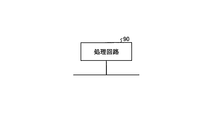
- FIG. 5 is a diagram showing a first example of the configuration of processing circuits for realizing the functions of the base station 1A and the mobile station 2A shown in FIG.
- the processing circuit 90 is one of a composite circuit, a programmed processor, a parallel programmed processor, an application specific integrated circuit (ASIC), and a field-programmable gate array (FPGA), or a combination thereof.
- a part or all of the functions of the modem unit 13, the base station control unit 14, the used channel selection unit 15, and the mobile station control unit 24 can be realized using the processing circuit 90 which is dedicated hardware.
- FIG. 6 is a diagram showing a second example of the configuration of the processing circuit for realizing the functions of the base station 1A and the mobile station 2A shown in FIG.
- the processing circuit 91 includes a processor 92 and a memory 93.
- the processor 92 is a CPU (Central Processing Unit), and is also called a central processing unit, a processing unit, an arithmetic unit, a microprocessor, a microcomputer, a DSP (Digital Signal Processor) or the like.
- CPU Central Processing Unit
- DSP Digital Signal Processor
- the memory 93 is a nonvolatile or volatile semiconductor memory such as a RAM (Random Access Memory), a ROM (Read Only Memory), a flash memory, an EPROM (Erasable Programmable ROM), an EEPROM (Electrically EPROM), a magnetic disk, or the like.
- RAM Random Access Memory
- ROM Read Only Memory
- flash memory an EPROM (Erasable Programmable ROM), an EEPROM (Electrically EPROM), a magnetic disk, or the like.
- the processor 92 reads out and executes a computer program stored in the memory 93, whereby some or all of the functions of the modem unit 13, the base station control unit 14, the used channel selection unit 15, and the mobile station control unit 24 are It can be realized using a processing circuit 91 including a processor 92 and a memory 93.
- the memory 93 is also used as a temporary memory in each process executed by the processor 92.
- FIG. 7 is a sequence diagram showing an operation of the wireless communication system 10 shown in FIG. In FIG. 7, it is assumed that n mobile stations 2A are located in the cell of the base station 1A. Hereinafter, in the case where each of the plurality of mobile stations 2A is distinguished, it is indicated as a mobile station 2A-1, a mobile station 2A-2, a mobile station 2A-n or the like.
- the management device 6 calculates the stop limit position of each vehicle 3 (step S101).
- the series of operations shown in FIG. 7 are repeatedly executed, and the management device 6 acquires the position information of each vehicle 3 from the mobile station 2A by performing the previous series of operations, and using these position information Calculate the stop limit position.
- the management device 6 transmits the calculated stop limit position to the base station 1A (step S102).
- the base station control unit 14 of the base station 1A receives the stop limit position transmitted by the management device 6, the base station control unit 14 generates broadcast information which is information to be transmitted to all the mobile stations 2A located in the cell of the base station 1A.
- the signal is output to the modem unit 13 (step S103).
- the broadcast information includes hopping information necessary for the mobile station 2A to generate a hopping pattern of a frame, a frame number, a cell number, allocation information of time slots for each mobile station 2A, and the like.
- the modulation / demodulation unit 13 of the base station 1A outputs, to the radio communication unit 12, the broadcast information subjected to the modulation processing and the like.
- the radio communication unit 12 transmits the broadcast information output from the modem unit 13 to all the mobile stations 2A located in the cell of the base station 1A (step S104).
- the use channel selection unit 15 of the base station 1A selects the frequency channel to be used to transmit the broadcast information based on the hopping information notified to the mobile station 2A using the broadcast information included in the previously transmitted frame. Do.
- the wireless communication unit 12 transmits broadcast information using the selected frequency channel.
- each of the use channel selection unit 15 of the base station 1A and the use channel selection unit 15 of the mobile station 2A selects a frequency channel to be used in each time slot.
- a hopping pattern is generated (step S105).
- the use channel selection unit 15 of the mobile station 2A can grasp the time slot assigned to itself based on the hopping information included in the broadcast information received from the base station 1A.
- the radio communication unit 12 of the mobile station 2A can perform radio communication with the base station 1A by performing radio processing using the same frequency channel as the frequency channel used by the base station 1A in the allocated time slot.
- FIG. 7 is a step of generating a hopping pattern, and a plurality of frequency channels to be used are selected collectively for each time slot, the present invention is not limited to this example.
- the selection of frequency channels to use may be made one for each time slot. Details of the method of generating the hopping pattern will be described later.
- the base station control unit 14 of the base station 1A transmits the stop limit position of the vehicle 3 mounted with the mobile station 2A received from the management device 6 to each mobile station 2A using different time slots (step S106) . Specifically, the base station control unit 14 transmits the stop limit position # 1 of the mobile station 2A-1 to the mobile station 2A-1 using the time slot following the time slot in which the broadcast information is transmitted, and the next The stop limit position # 2 of the mobile station 2A-2 is transmitted to the mobile station 2A-2 using the time slot. The same processing is repeated until the stop limit position #n of the n-th mobile station 2A-n is transmitted to the mobile station 2A-n.
- each mobile station 2A uses the time slot to which it is allocated to indicate the current position of the mobile station 2A, that is, the position of the vehicle 3 on which each mobile station 2A is mounted.
- the information is transmitted to the base station 1A (step S107).
- the mobile station 2A-1 transmits the position information # 1 of the mobile station 2A-1 to the base station 1A using the time slot following the time slot in which the stop limit position #n has been transmitted.
- the mobile station 2A-2 transmits the position information # 2 of the mobile station 2A-2 to the base station 1A, and the same processing is repeated until the mobile station 2A-n transmits the position information #n to the base station 1A.
- the base station 1A transmits the received position information to the management device 6 via the wired network 5 (step S108).
- the position information transmitted to the management device 6 in step S108 is used when the management device 6 calculates the stop limit position in step S101 in the next series of operations. .
- the series of operations shown in FIG. 7 are performed in a time cycle of several hundred milliseconds.
- the stop limit position is updated at a constant cycle, and the train can be operated.
- the on-vehicle control device 31 performs control to stop the vehicle 3 when the update of the stop limit position is stopped.
- the mobile station control unit 24 of the mobile station 2A performs handover processing to switch the base station 1A of the communication destination when the vehicle 3 moves and the mobile station 2A is positioned in the cell of the adjacent base station 1A.
- FIG. 8 is a diagram showing a frame configuration transmitted during the operation shown in FIG.
- the i-th frame #i transmitted between the base station 1A and the n mobile stations 2A is broadcast information # It includes i, n stop limit positions # 1 to stop limit positions #n, and n position information # 1 to position information #n.
- Each frame is comprised of time slots of fixed length of time. Broadcast information is stored in the leading time slot of each frame. The broadcast information, the stop limit position and the position information are transmitted using different time slots.
- FIG. 9 is a diagram showing the concept of the method of assigning frequency channels to each base station 1A of the wireless communication system 10 shown in FIG.
- the number of frequency channel candidates is sixteen.
- Base station 1A-1 and base station 1A-2 use different frequency channels in the same time slot. When focusing on a specific base station 1A, frequency channels to be used are shifted one by one for each time slot.
- Hopping patterns in which frequency channels do not overlap with other hopping patterns in all time slots can be generated up to the number of frequency channel candidates. That is, when the frequency channel candidate is 16 from f 0 to f 15 , 16 hopping patterns can be generated. In this case, the interval between cells to which the frequency channel is assigned the same hopping pattern in all time slots is at most 16 cells.
- the visibility between the base stations 1A may be poor, and the possibility of receiving interference from radio waves from the base stations 1A having 16 cells apart may be low.
- all time slots may be received because there may be interference of radio waves from base station 1A arranged further. It is desirable to expand the spacing of cells to which frequency channels are assigned the same hopping pattern. Therefore, in the present embodiment, in the cells within the number of frequency channel candidates, cells in which frequency channels used in all time slots are assigned the same hopping pattern while allowing partially overlapping frequency channels to be used are allowed. The interval of is made larger than the number of frequency channel candidates.
- the use channel selection unit 15 uses a frequency channel in which adjacent cells within a first number of cells for which the number of cells from cells used by the wireless communication unit 12 for wireless communication is predetermined are used in the same time slot. Select a different frequency channel.
- the cell used by the wireless communication unit 12 for wireless communication is a cell formed by the base station 1 for the used channel selection unit 15 of the base station 1 and for the used channel selection unit 15 of the mobile station 2A, the cell used by the mobile station 2A. It is a cell that covers the position.
- the use channel selection unit 15 determines that the selected frequency channel overlaps the frequency channel used in the same time slot with remote cells within the number of frequency channel candidates whose cell spacing is greater than the first number of cells. Tolerate.
- the use channel selection unit 15 determines the first cell number so that a plurality of remote cells exist, and selects a frequency channel to be used so that frequency channels overlap with a plurality of remote cells in order. By setting the first number of cells in this way, when focusing on two of the remote cells, frequency channels do not overlap in all time slots, so it is possible to suppress the occurrence of radio wave interference. become.
- one time slot is allocated to one vehicle 3 per one frame, but the present invention is not limited to this example.
- a plurality of time slots may be allocated to one vehicle 3 in one frame. Even when a plurality of time slots are assigned to one vehicle 3 in one frame, the frequency channel used for each time slot changes, so interference resistance can be improved.
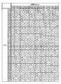
- FIG. 10 is a diagram showing an example of hopping patterns generated by the use channel selection unit 15 shown in FIGS. 2 and 4.
- the number of frequency channel candidates is sixteen.
- the numbers corresponding to each time slot and cell are frequency channel numbers that identify frequency channels. Focusing on the cell # 16, the frequency channel # 0 of the time slot # 0 and the frequency channel # 12 of the time slot # 4 overlap with the cell # 0 separated by 16 cells.
- Frequency channel # 7 of time slot # 1 overlaps cell # 1 that is 15 cells away.
- Frequency channel # 14 of time slot # 2 overlaps cell # 2 which is 14 cells away.
- Frequency channel # 5 of time slot # 3 overlaps cell # 3 which is 13 cells away.
- the cells to which the frequency channel overlapping with the frequency channel to be allocated to cell # 16 is to be allocated are grouped into four cells of cell # 0 to cell # 3, and the cell # 4 to cell # 15 are in the same time slot. Assign a frequency channel different from the frequency channel assigned to 16.
- the use channel selection unit 15 can generate a hopping pattern by selecting a frequency channel to be used in each time slot by using the following equation (1).
- M is the number of cells in the system
- N is the number of slots in the frame.
- the cell number i has a value of 0 to M-1
- the time slot number j in the frame has a value of 0 to N-1.
- mod (A, B) is the remainder when A is divided by B.
- m is a remainder when the quotient obtained by dividing the cell number i by the number 16 of frequency channel candidates is further divided by 2 and is expressed by the following equation (2), and takes a value of 0 or 1. Since m takes a different value every 16 cells, hopping patterns separated by 16 cells include different frequency channels.
- n is a remainder obtained by dividing the cell number i by the number 16 of frequency channel candidates, which is expressed by the following equation (3), and takes any value of 0 to 15. n takes a value for each cell.
- D [m] is the spacing of frequency channels between time slots, and in this example takes a value of 3 or 7 depending on the value of m.
- s [n] is an offset of the hopping pattern between cells, and in this example, 0, 4, 8, 12, 1, 5, 9, 13, 13, 11, 15, 12, 6, 6, depending on the value of n. Takes one of 10 and 14 values.
- Equation (1) if the frequency channel spacing d [m] between the slots is constant, the use channel selection unit 15 sets different frequency channels in the same time slot between different offsets s [n]. Will be selected. Also, by changing d [m] for each cell of the number of frequency channel candidates, different frequency channels are selected in cells separated by the number of frequency channel candidates.
- Equation (1) since the remainder of the number 16 of frequency channel candidates is taken, the possible values of d [m] are 1 to 15. If a divisor of the number of candidates other than 1 is selected, an unused frequency channel will be generated, and the hopping pattern will be repeated with a shorter cycle than the number of frequency channel candidates. Therefore, an odd number is used here as the value of d [m].
- the combination of d [m] affects the rate at which the same frequency channel is selected among different cells of d [m].
- s [n] (0, 4, 8, 12, 1, 5, 9, 13, 3, 7, 11, 15, 2, 6, 10, 14), Those whose values are multiples of 4 are collectively arranged in adjacent cells. Therefore, frequency channel duplication occurs at a rate of one slot every four time slots for s [0] to s [3], and no frequency channel duplication occurs for s [4] to s [15]. .
- frequency channels overlap at a rate of 1 in every 4 time slots in 4 cells, but by changing the combination of d [m], 1 out of every 8 time slots in 8 cells
- the frequency channels may overlap, or the frequency channels may overlap at a rate of one every two time slots in two cells.
- the values of d [m] and s [n] are assigned in advance to each base station 1A, and the used channel selection unit 15 of the base station 1A receives d [m] given from the base station control unit 14.
- a hopping pattern is generated by selecting the frequency channel to be used for each time slot using the values of m] and s [n].
- the values of d [m] and s [n] are included in the above hopping information, and are transmitted to the mobile station 2A located in the cell of each base station 1A.
- the use channel selection unit 15 of the mobile station 2A uses the values of d [m] and s [n] acquired via the mobile station control unit 24 to select the frequency channel to be used for each time slot, thereby performing hopping. Generate a pattern.
- hopping patterns as shown in FIG. 10 can be generated.
- time slot # 0 to time slot # 15 are shown in FIG. 10, the same applies to time slots # 16 and more.
- cell # 0 to cell # 31 are shown, in cell # 32, the same hopping pattern as cell # 0 is used again. That is, the interval of cells in which frequency channels used in all time slots overlap is 32 cells, which is larger than the number 16 of frequency channel candidates.
- the frequency channels assigned to specific time slots in a frame overlap among a plurality of frames, so an offset is provided. It is desirable to shift the frequency channel allocated for each frame. In this case, if the same information is transmitted a plurality of times over a plurality of frames, the frequency channels overlap at all transmissions of the same information, resulting in cells separated by 32 cells.
- the selection of the frequency channel to be used is performed in parallel with the processing for performing wireless communication, but the present invention is not limited to this example.
- the timing for selecting a frequency channel to be used is not limited to the above example, and may be before starting wireless communication.
- the frequency channel to be used may be selected in advance using the above method and the hopping pattern may be held as a table, and the use channel selection unit 15 may select the frequency channel for each time slot according to the table.
- the use channel selection unit 15 of the base station 1A and the mobile station 2A does not have to have a circuit for performing the calculation shown in the above equation (1), and the circuit configuration Can be simplified.
- the number of cells from cells used for wireless communication by the wireless communication unit 12 is predetermined.
- the adjacent cells within the first number of cells select a frequency channel different from the frequency channel used in the same time slot, and the frequency channel to be selected has a cell spacing within the number of frequency channel candidates and the first cell. It is permitted that more than a number of remote cells overlap with the frequency channel used in the same time slot.
- By using such frequency channels it is possible to make the distance between cells using hopping patterns in which frequency channels used in all time slots overlap each other is larger than the number of frequency channel candidates. Therefore, it becomes possible to suppress the interference of radio waves in the system, and it becomes possible to realize stable wireless communication.
- FIG. 11 is a diagram showing the configuration of the wireless communication system 20 according to the second embodiment of the present invention.
- the wireless communication system 20 has a configuration of generating two hopping patterns and selecting a frequency channel for each time slot from the generated two hopping patterns.
- the wireless communication system 20 has a base station 1B instead of the base station 1A of the wireless communication system 10, and has a mobile station 2B instead of the mobile station 2A.
- the wireless communication system 20 also includes a monitoring device 7 that monitors the state of communication quality in the system.
- the wireless communication system 20 can include three or more base stations 1B. Although one vehicle 3 and one mobile station 2B are shown in FIG. 11, the wireless communication system 20 can include a plurality of mobile stations 2B mounted on a plurality of vehicles 3.
- the monitoring device 7 is connected to the wired network 5 and can communicate with the base station 1 B via the wired network 5.
- Each of the base station 1B and the mobile station 2B has a function of measuring a quality value indicating communication quality, and the monitoring device 7 collects the quality values measured by each of the base station 1B and the mobile station 2B. Monitor the communication quality in the system, that is, the state of the radio wave environment based on the collected quality value.
- the monitoring device 7 detects that the communication quality has deteriorated, it issues a warning to the system administrator.
- the communication quality varies depending on the frequency channel used and also varies depending on the measurement position in the cell. Therefore, it is desirable that the quality value be managed together with the frequency channel used and the measurement position in the cell.
- each of the base station 1B and the mobile station 2B transmits the used frequency channel and the measurement position to the monitoring device 7.
- the monitoring device 7 generates and stores a database of quality values for each frequency channel and each measurement position.
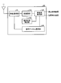
- FIG. 12 is a diagram showing an example of the configuration of a database generated by the monitoring device 7 shown in FIG.
- the horizontal axis in FIG. 12 indicates the measurement position of the quality value in the cell of each base station 1B, and the vertical axis in FIG. 12 indicates the frequency channel.
- the monitoring device 7 stores the quality value in the storage area corresponding to the measurement position and frequency channel associated with the received quality value.
- the measurement position defines a block obtained by dividing the cell of the base station 1B at a predetermined distance, and is represented using this block.
- Monitoring device 7 manages the quality value for each base station 1B, in the example of FIG. 12, l 1C from the block l 11 indicating the position indicates a position in the cell formed by the base station 1B-1, l 2C from the block l 21 indicates the position in the cell formed by the base station 1B-2.
- the quality value stored in the database is data indicating the radio wave environment for each measurement position in the cell, that is, the communication quality, and the signal-to-interference noise power ratio, which is the ratio of signal to noise, and the probability of receiving erroneous data on the receiving side Packet error rate, etc.
- each base station 1B measures the received power
- each mobile station 2B measures the received power and the interference noise power.
- the monitoring device 7 monitors the communication quality when the mobile station 2B receives the data transmitted by the base station 1B and the communication quality when the base station 1B receives the data transmitted by the mobile station 2B.
- a database can be generated that stores each of the quality values indicative of both.
- the monitoring device 7 can update the database while averaging the quality values for each measurement. For averaging, a moving average using quality values within a certain period from the latest quality value may be used, or a forgetting factor may be used.
- the monitoring device 7 distributes the quality values stored in the generated database to the respective base stations 1B. Specifically, the monitoring device 7 determines each quality value stored in the database in association with a block in a cell formed by each base station 1B while keeping the correspondence with the block, that is, the measurement position and the frequency channel maintained. Deliver to station 1B.
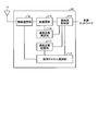
- FIG. 13 is a diagram showing a configuration of base station 1B shown in FIG.
- Base station 1 B includes communication antenna 11, wireless communication unit 12, modulation / demodulation unit 113, base station control unit 114, used channel selection unit 115, communication quality measurement unit 116, and communication quality storage unit 117. .
- the functions of the communication antenna 11 and the wireless communication unit 12 are the same as in the first embodiment, and therefore the description thereof is omitted here.
- the modem unit 113 has the same function as the modem unit 13, the base station control unit 114 has the same function as the base station control unit 14, and the used channel selection unit 115 is similar to the used channel selection unit 15.
- Have the function of The functions of the modem unit 113, the base station control unit 114 and the used channel selection unit 115 are different from the modem unit 13, the base station control unit 14 and the used channel selection unit 15 in that processing using a quality value indicating communication quality is performed. .
- the communication quality measurement unit 116 measures the quality value indicating the communication quality of the received signal using the received processing result. Specifically, the communication quality measurement unit 116 measures a radio wave environment when communication is not performed as interference noise power and measures a power value of received power. The communication quality measurement unit 116 calculates a signal-to-interference noise power ratio using the measured power value of the received signal and the interference noise power. The communication quality measurement unit 116 outputs the measured quality value to the base station control unit 114 together with the frequency channel and measurement position used when the quality value was measured. The measurement position is the position of the mobile station 2B at which the interference noise power used to calculate the quality value is measured.
- the base station control unit 114 transmits the quality value, the frequency channel, and the measurement position output by the communication quality measurement unit 116 to the monitoring device 7 via the wired network 5.
- the base station control unit 114 transmits the received quality value to the monitoring device 7 via the wired network 5.
- the base station control unit 114 acquires the quality value associated with the measurement position and the frequency channel that the monitoring device 7 delivers from the database, and the communication quality in a state where the acquired quality value is associated with the measurement position and the frequency channel. It is stored in the storage unit 117.
- the configuration is such that the quality values are collected into the monitoring device 7 and then distributed to each base station 1B, the present invention is not limited to such an example. It is only necessary to create a database of quality values associated with measured positions in the cell of base station 1B and frequency channels, and each base station 1B creates a database for each base station 1B and copies of the database It may be sent to the monitoring device 7.
- the use channel selection unit 115 selects a frequency channel to be used based on the quality value stored in the communication quality storage unit 117.
- the use channel selection unit 115 extracts a plurality of frequency channels for each time slot, and among the extracted frequency channels, the communication quality is the best among the extracted frequency channels based on the quality value for each frequency channel. Select one frequency channel.
- the use channel selection unit 115 stores selection information indicating the selected frequency channel, which is information for identifying the hopping pattern in which the selected frequency channel is included.
- the use channel selection unit 115 can generate two hopping patterns by selecting two use channels for each time slot using Equation (4) shown below.
- Equation (4) is a value for identifying two hopping patterns to be generated, and takes a value of 0 or 1.
- the definitions of the symbols in Formula (4) are the same as in Embodiment 1 except for k.
- the use channel selection unit 115 extracts two frequency channels for each time slot from the frequency channel candidates using Equation (4) to generate two hopping patterns.
- Equation (4) has a pattern in which s [n] is shifted by eight cells by changing d [k] as compared with the frequency channel selection method of equation (1).
- the hopping pattern is generated using Equation (4), in the adjacent cells with the number of cells between cells of 1 to 4, there is no duplication of frequency channels, and four remote cells with the number of cells of 5 to 8 between cells. In this case, frequency channel duplication occurs at a rate of once every four times.
- FIG. 14 is a diagram showing an example of a first pattern of hopping patterns generated by the use channel selection unit 115 shown in FIG.
- FIG. 15 is a diagram showing an example of a second pattern of the hopping pattern generated by the use channel selection unit 115 shown in FIG.
- the hopping pattern shown in FIG. 14 and the hopping pattern shown in FIG. 15 are a pair of hopping patterns generated using Equation (4).
- the cell # 16 has the same hopping pattern as the cell # 0. Focusing on the hopping pattern of cell # 8 in FIG. 14, when only the pattern shown in FIG. 14 is seen, the frequency channel and the frequency channel of time slot # 0 overlap is a cell separated by 16 cells. .
- frequency channel # 0 is selected in cell # 8
- the eight remote cells are allowed to overlap frequency channels at a rate of once every four time slots.
- the number of cells between cells in which frequency channels overlap over all time slots is 16.
- the number of frequency channel candidates is 16 and two frequency channels are extracted to generate two hopping patterns, generate eight hopping patterns in which the frequency channels do not overlap over all time slots. Can. For this reason, although the same hopping pattern is repeated every eight cells, in the present embodiment, by allowing overlapping of the frequency channel with the remote cell, the frequency channel overlaps in all time slots.
- the spacing between can be expanded to sixteen.
- the frequency channel spacing between time slots is constant regardless of the cell number, but the frequency channel spacing between time slots is determined by cell number i as in the first embodiment. You may change it. In this case, as in the first embodiment, the interval between cells in which frequency channels overlap can be further expanded over all time slots.
- the use channel selection unit 115 selects the frequency channel to be used in each time slot using Equation (5) below to obtain the hopping pattern. Can be generated.
- Equation (2) is the remainder when the quotient obtained by dividing the cell number i by 16 is further divided by 2 as in the first embodiment. Takes a value of 0 or 1.
- the spacing d [k, m] of the frequency channel between time slots is expressed by the following equation (6).
- FIG. 16 is a diagram showing a modification of the first pattern of the hopping pattern generated by the use channel selection unit 115 shown in FIG.
- FIG. 17 is a diagram showing a modification of the second pattern of the hopping pattern generated by the use channel selection unit 115 shown in FIG.
- the hopping pattern shown in FIG. 16 and the hopping pattern shown in FIG. 17 are a pair of hopping patterns generated using Expression (5).
- the cell spacing between cells in which frequency channels overlap in all time slots can be set to 32, which is larger than in the case of using equation (4). be able to.
- the use channel selection unit 115 of the base station 1B When one frequency channel is selected from the two frequency channels, the use channel selection unit 115 of the base station 1B generates selection information indicating the selected frequency channel and outputs the selection information to the base station control unit 114. The base station control unit 114 transmits the selection information to the mobile station 2B.
- FIG. 18 shows a configuration of mobile station 2B shown in FIG.
- the mobile station 2B includes a communication antenna 11, a wireless communication unit 12, a modulation / demodulation unit 113, a communication quality measurement unit 126, a mobile station control unit 124, and a use channel selection unit 125.
- the functions of the communication antenna 11 and the wireless communication unit 12 are the same as in Embodiment 1, and the functions of the modem unit 113 are the same as the functions of the modem unit 113 of the base station 1B shown in FIG.
- the mobile station control unit 124 and the use channel selection unit 125 are different from the mobile station control unit 24 and the use channel selection unit 15 in that processing using a quality value indicating communication quality is performed.
- the communication quality measuring unit 126 measures the quality value indicating the communication quality of the received signal using the received processing result. Specifically, the communication quality measurement unit 126 measures the power value of the received signal and the interference noise power indicating the radio wave environment when communication is not performed. The communication quality measurement unit 126 divides the measured power value by the interference noise power to calculate a signal-to-interference noise power ratio, and sets it as a quality value. The communication quality measurement unit 126 outputs the measured quality value, the measured interference noise power, the measurement position of the quality value, and the used frequency channel to the mobile station control unit 124.
- the mobile station control unit 124 transmits the quality value output by the communication quality measurement unit 126, the measurement position, and the frequency channel to the base station 1B. Further, upon receiving the selection information and the hopping information from the base station 1B, the mobile station control unit 124 outputs the selection information and the hopping information to the use channel selection unit 125.
- the use channel selection unit 125 selects a frequency channel selected by the base station 1B for each time slot among the plurality of frequency channels, and outputs the selected frequency channel to the wireless communication unit 12.
- the use channel selection unit 125 When the selection information and the hopping information are received from the mobile station control unit 124, the use channel selection unit 125 generates a plurality of hopping patterns in the same manner as the use channel selection unit 115, and the frequency channel according to the selection information for each time slot. Choose Such a configuration makes it possible to perform wireless communication using the same frequency channel as that of the base station 1B.
- the modem unit 113, the base station control unit 114, the used channel selection unit 115, the communication quality measurement unit 116, the communication quality storage unit 117, the mobile station control unit 124, the used channel selection unit 125 and the communication quality measurement unit 126 are processing circuits. is there. This processing circuit may be dedicated hardware or may be a processing circuit using a computer program.
- the processing circuit When dedicated hardware is used, the processing circuit is the processing circuit 90 shown in FIG. When a computer program is used, the processing circuit is the processing circuit 91 shown in FIG.
- the functions of the base station 1B and the mobile station 2B may be realized by using a processing circuit 90 which is dedicated hardware and a processing circuit 91 using a computer program in combination.
- FIG. 19 is a sequence diagram showing an operation of the wireless communication system 20 shown in FIG. 11
- the wireless communication system 20 comprises a plurality of base stations 1B and a plurality of mobile stations 2B located in the cells of the respective base stations 1B, but for the sake of simplicity here, one base station 1B And one mobile station 2B.
- the communication quality measurement unit 126 of the mobile station 2B measures the quality value at a constant cycle (step S201).
- the mobile station 2B transmits the measured quality value to the base station 1B using wireless communication (step S202).
- the base station control unit 114 of the base station 1B transmits the quality value received from the mobile station 2B to the monitoring device 7 using the wired network 5 (step S203).
- the communication quality measurement unit 116 of the base station 1B measures the quality value at a constant cycle and outputs the measured quality value to the base station control unit 114 (step S204).
- the base station control unit 114 of the base station 1B transmits the quality value to the monitoring device 7 using the wired network 5 (step S205).
- the monitoring device 7 updates the quality value database using the received quality value (step S206).
- the monitoring device 7 transmits the quality value database to the base station 1B (step S207).
- the use channel selection unit 115 When the base station 1B stores the quality value database transmitted by the monitoring device 7 in the communication quality storage unit 117, the use channel selection unit 115 generates two frequency channels for each time slot (step S208). Then, the use channel selection unit 115 selects one frequency channel from two frequency channels for each time slot based on the quality value (step S209). The base station 1B generates selection information indicating the frequency channel selected in step S209, and transmits the generated selection information to the mobile station 2B (step S210). The base station 1B can store the selection information, d [k], and s [n] in the broadcast information described in the first embodiment and transmit the information to the mobile station 2B.
- the use channel selection unit 125 of the mobile station 2B generates two hopping patterns using d [k] and s [n] received from the base station 1B, and uses two selection patterns and two hopping patterns. And one frequency channel is selected for each time slot to generate one hopping pattern (step S211).
- the configuration shown in the above embodiment shows an example of the contents of the present invention, and can be combined with another known technique, and one of the configurations is possible within the scope of the present invention. Parts can be omitted or changed.
- wireless communication is performed using the ISM band, but the present invention is not limited to such an example.
- the techniques of the present invention can be applied to a system using a radio band that may cause interference with other systems.
- the route 4 is a track
- the vehicle 3 is a train
- control information for performing train operation control, speed control, etc. is transmitted from the base station to the mobile station using radio communication.
- the route 4 may be a road such as an expressway
- the vehicle 3 may be a car
- the base station may be a road-vehicle communication system provided in a roadside unit.
- control information of the vehicle is transmitted using wireless communication as in the above embodiment.
- the information transmitted from the base station to the mobile station may not be information used for control of the vehicle 3 but may be information simply displayed on a display device mounted on the vehicle 3 or the like.
- two frequency channels are extracted for each time slot in parallel with the process for performing wireless communication, but the present invention is not limited to this example.
- Two hopping patterns may be created in advance using the same method as described above, and the used channel selection unit 115 may hold it.
- the use channel selection unit 115 selects a frequency channel to be used for each time slot from two pre-generated hopping patterns based on the quality value.
- the use channel selection unit 115 of the base station 1B and the use channel selection unit 125 of the mobile station 2B perform the calculation shown in the above equation (4) or equation (5). It is not necessary to have a circuit for the purpose, and the circuit configuration can be simplified.
- the base station 1B and the mobile station 2B which are the wireless communication devices according to the second embodiment of the present invention, from the cell used by the wireless communication unit 12 for the wireless communication as in the first embodiment.
- the adjacent cells within the first cell number having a predetermined number of cells select a frequency channel different from the frequency channel used in the same time slot, and the frequency channel to be selected is the number of frequency channel candidates for the cell spacing. It is allowed that remote cells within the range and larger than the first number of cells overlap with frequency channels used in the same time slot. By using such frequency channels, it is possible to extend the spacing between cells using hopping patterns in which frequency channels used in all time slots overlap, as compared to the case where the frequency channels do not allow overlapping. Therefore, it becomes possible to suppress the interference of radio waves in the system, and it becomes possible to realize stable wireless communication.
- a frequency channel is selected for each time slot from among the two frequency channels selected as described above, based on the quality value. For this reason, it is possible to select a frequency channel in which the radio wave condition at that time is good. Therefore, the interference of radio waves can be further suppressed, and stable wireless communication can be realized.
- the frequency channel used in each cell is selected by processing closed only inside the base station 1A and the base station 1B.
- the frequency channel used in each cell is selected by processing closed only inside the base station 1A and the base station 1B.
- responses when aggregating train position information or distributing the selected hopping pattern Time is an issue.
Landscapes
- Engineering & Computer Science (AREA)
- Signal Processing (AREA)
- Computer Networks & Wireless Communication (AREA)
- Aviation & Aerospace Engineering (AREA)
- Mobile Radio Communication Systems (AREA)
Abstract
無線通信装置(1A,2A)は、予め定められた複数の周波数チャネルの候補から1つの周波数チャネルを時間スロット毎に選択する使用チャネル選択部(15)と、使用チャネル選択部が選択した周波数チャネルを用いて、無線通信を行う無線通信部(12)とを備える。使用チャネル選択部(15)は、無線通信に用いるセルからのセル数が予め定められた第1のセル数以内の近接するセルが同じ時間スロットにおいて使用する周波数チャネルと異なる周波数チャネルを選択し、無線通信に用いるセルからのセル数が周波数チャネルの候補の数以内であって第1のセル数よりも大きい遠隔セルが同じ時間スロットにおいて使用する周波数チャネルと、選択した周波数チャネルとが重複することを許容することを特徴とする。
Description
本発明は、周波数ホッピングを用いる無線通信装置、無線通信システムおよび無線通信方法に関する。
近年、線路沿いに設置された地上局と列車との間で無線通信を行い、この無線通信を用いて伝送された情報に基づいて、列車の運行制御、速度制御などを行う無線列車制御システムが注目されている。無線列車制御システムでは、電波の利用免許が不要な2.4GHzのISM(Industry-Science-Medical)帯が使用されることが多い。ISM帯は、無線LAN(Local Area Network)、Bluetooth(登録商標)などのシステムによって広く使用されているため、他のシステムの電波との干渉を抑制するためにスペクトラム拡散技術が用いられることがある。スペクトラム拡散技術は、信号を元の信号よりも広い帯域に拡散して通信する技術である。
特許文献1には、スペクトラム拡散技術の一種である周波数ホッピングを用いる無線通信システムが開示されている。周波数ホッピングは、時間スロット毎に異なる周波数チャネルを使用して無線通信を行う技術である。特許文献1に記載のシステムでは、同じ時間スロットに対応する周波数チャネルが互いに異なる2つのホッピングパターンを準備しておき、電波状況に応じて、使用する周波数チャネルを時間スロット毎に2つのホッピングパターンの中から選択している。
しかしながら、全ての時間スロットで同時に用いられる周波数チャネルが重複しないホッピングパターンの数は、用いられる周波数チャネルの候補の数と同じとなる。このため、上記特許文献1に記載の技術によれば、同一のホッピングパターンを用いるセルの間隔は、最大でも周波数チャネルの候補の数となる。上記の無線列車制御システムのように基地局が線路に沿って並べられる場合などは、基地局間の見通しがよいことが多く、他の基地局からの電波の干渉を受ける可能性が高まり、システム内の電波の干渉が増大するという問題があった。
本発明は、上記に鑑みてなされたものであって、システム内の電波の干渉を抑制することが可能な無線通信装置を得ることを目的とする。
上述した課題を解決し、目的を達成するために、本発明にかかる無線通信装置は、予め定められた複数の周波数チャネルの候補から1つの周波数チャネルを時間スロット毎に選択する使用チャネル選択部と、使用チャネル選択部が選択した周波数チャネルを用いて、無線通信を行う無線通信部とを備える。使用チャネル選択部は、無線通信に用いるセルからのセル数が予め定められた第1のセル数以内の近接するセルが同じ時間スロットにおいて使用する周波数チャネルと異なる周波数チャネルを選択し、無線通信に用いるセルからのセル数が周波数チャネルの候補の数以内であって第1のセル数よりも大きい遠隔セルが同じ時間スロットにおいて使用する周波数チャネルと、選択した周波数チャネルとが重複することを許容することを特徴とする。
本発明にかかる無線通信装置は、システム内の電波の干渉を抑制することが可能であるという効果を奏する。
以下に、本発明の実施の形態にかかる無線通信装置、無線通信システムおよび無線通信方法を図面に基づいて詳細に説明する。なお、この実施の形態によりこの発明が限定されるものではない。
実施の形態1.
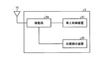
図1は、本発明の実施の形態1にかかる無線通信システム10の構成を示す図である。無線通信システム10は、基地局1A-1と、基地局1A-2と、移動局2Aと、有線ネットワーク5と、管理装置6とを有する。
図1は、本発明の実施の形態1にかかる無線通信システム10の構成を示す図である。無線通信システム10は、基地局1A-1と、基地局1A-2と、移動局2Aと、有線ネットワーク5と、管理装置6とを有する。
基地局1A-1および基地局1A-2は、予め定められた経路4に沿って配置される無線通信装置である。以下、基地局1A-1および基地局1A-2のそれぞれを特に区別する必要がない場合、基地局1A-1および基地局1A-2をまとめて基地局1Aと称する。基地局1Aが配置される経路4は、線路などである。経路4が線路である場合、車両3は列車となる。また経路4が道路であって、車両3が自動車であってもよい。以下、経路4が線路であり、車両3が列車である場合について説明する。基地局1Aは、経路4に沿って数十メートルから数百メートルの間隔で設置される。
移動局2Aは、車両3に搭載された無線通信装置である。車両3は、経路4に沿って移動する。図1には1台の車両3と1台の移動局2Aとが示されているが、実際には無線通信システム10は複数の移動局2Aを備えている。
複数の基地局1Aは、有線ネットワーク5に接続されている。管理装置6は、有線ネットワーク5に接続されており、車両3の運行を管理する。管理装置6は、基地局1Aと移動局2Aとの間で行われる無線通信を用いて伝送された情報に基づいて、車両3の運行制御、速度制御などを行う。無線式の列車制御システムは、従来の固定閉塞区間による列車運行制御方式と比較して、軌道回路が不要であるため、導入コストおよびメンテナンスコストを低減することができる。また、固定的な区間に囚われない柔軟な閉塞区間を構築することが可能なため、列車の運行密度を上げることが可能となり、運行コストを低減することができる。
無線通信システム10が無線通信に用いる周波数帯域は、電波の利用免許が不要な周波数帯域であり、ISM帯などである。ISM帯は、上記の通り無線LAN、Bluetoothなど複数のシステムによって利用されている。一般的にセル構成をとる無線通信システムでは、セルの大きさは送信機の送信電力と受信機の受信感度に大きく依存し、セルの端での受信レベルが受信感度付近となるように基地局が配置される。これに対して本実施の形態にかかる基地局1Aは、他システムからの干渉が多い中でも通信ができるように、基地局1Aが形成するセルの端部における受信レベルが受信感度よりも高いレベルとなるような間隔で配置することができる。またシステム間の電波の干渉を低減するために、基地局1Aと移動局2Aとは周波数ホッピングを用いた無線通信を行い、用いる周波数チャネルを時間スロット毎に切り替える。移動局2Aは、移動局2Aが搭載される車両3の現在の位置情報を、無線通信を用いて基地局1Aに送信している。基地局1Aは、それぞれの車両3が先行する車両3と衝突せずに安全に停止することができる限界の位置である停止限界位置など、管理装置6が車両3の運行制御、速度制御などのために生成する制御情報を、無線通信を用いて移動局2Aに伝送する。
しかしながら、上記の構成によって他システムからの電波の干渉を低減することはできても、基地局1Aをセルの端部における受信レベルが受信感度よりも高いレベルとなるような間隔で配置した場合には、同じ周波数チャネルを使用するより遠くの基地局1Aからの電波が干渉として入り込んでくる可能性が高まり、システム内の電波の干渉が生じることがある。また基地局1Aを線路など見通しのよい経路4に沿って配置するため、同じ周波数チャネルを使用するより遠くの基地局1Aからの電波が干渉として入り込んでくる可能性が高まる。システム内の電波の干渉を低減するために、全ての時間スロットにおいて同じ周波数チャネルを用いるホッピングパターンが同一の基地局1A同士の間の距離を離すことが望ましい。
図2は、図1に示す基地局1Aの機能構成を示す図である。基地局1Aは、通信アンテナ11と、無線通信部12と、変復調部13と、基地局制御部14と、使用チャネル選択部15とを有する。
通信アンテナ11は、送信時に無線通信部12から入力された無線信号を空中に放射するとともに、空中を伝搬してきた無線信号を受信して無線通信部12に入力する。無線通信部12は、送信時には変復調部13から入力されたデジタルで変調された信号をアナログ信号に変換し、キャリア周波数に周波数変換する。無線通信部12は、受信時には通信アンテナ11から入力されたアナログ信号をベースバンド帯に周波数変換し、周波数変換したアナログ信号をデジタル信号に変換する無線処理を行う。無線通信部12は、後述する使用チャネル選択部15が選択する周波数チャネルを用いて、無線処理を行う。
変復調部13は、送信時には送信データに対して符号化処理および変調処理を行い、受信時には受信した信号に対して復調処理および復号処理を行う。基地局制御部14は、送信時には有線ネットワーク5側からのデータの送信制御を行うと共に、受信時には、受信データを有線ネットワーク5側に出力する制御を行う。使用チャネル選択部15は、与えられた条件に基づいて、無線通信を行う際に用いる周波数チャネルを時間スロット毎に選択し、選択した周波数チャネルを識別する周波数チャネル番号を無線通信部12に出力する。使用チャネル選択部15の詳細な機能は後述する。
図3は、図1に示す車両3の概略構成を示す図である。車両3は、移動局2Aと、車上制御装置31と、位置検出装置32とを有する。移動局2Aは、通信アンテナ11を有する。車上制御装置31は、移動局2Aが受信したデータに基づいて、車両3の停止、速度変更など車両3の制御を行う。位置検出装置32は、車両3の位置を検出する。位置検出装置32は、一定の時間周期で車両3の位置を検出して位置情報を生成し、生成した位置情報を移動局2Aに出力することができる。位置検出装置32は、GPS(Global Positioning System)受信機を用いて位置情報を取得してもよいし、基地局1Aから移動局2Aに伝送された起点位置情報と車軸の回転速度を計測する速度発電機から得られる移動距離とに基づいて車両3の現在位置を計算してもよい。
図4は、図1に示す移動局2Aの機能構成を示す図である。以下、基地局1Aの構成要素と同様の機能を有する構成要素については、同一の符号を付して同様の機能についての説明を省略する。移動局2Aは、通信アンテナ11と、無線通信部12と、変復調部13と、移動局制御部24と、使用チャネル選択部15とを有する。移動局制御部24は、送信時には位置検出装置32が出力した位置情報に基づいて送信データを生成して、生成した送信データを変復調部13に出力する。移動局制御部24は、受信時には変復調部13から出力された復調データを車上制御装置31に出力する。
次に、基地局1Aおよび移動局2Aの機能を実現するためのハードウェア構成について説明する。基地局1Aおよび移動局2Aの無線通信部12は、周波数変換などを行うアナログ回路、アナログデジタルコンバータ、デジタルアナログコンバータなどを用いて構成される。変復調部13、基地局制御部14、使用チャネル選択部15および移動局制御部24は、処理回路である。この処理回路は、専用のハードウェアであってもよいし、コンピュータプログラムを用いる処理回路であってもよい。
専用のハードウェアを用いる場合、処理回路は、図5に示す処理回路90である。図5は、図1に示す基地局1Aおよび移動局2Aの機能を実現するための処理回路の構成の第1の例を示す図である。
処理回路90は、複合回路、プログラム化したプロセッサ、並列プログラム化したプロセッサ、ASIC(Application Specific Integrated Circuit)、およびFPGA(Field-Programmable Gate Array)のいずれか、またはこれらを組み合わせたものである。変復調部13、基地局制御部14、使用チャネル選択部15および移動局制御部24の機能の一部または全部は、専用のハードウェアである処理回路90を用いて実現することができる。
コンピュータプログラムを用いる場合、処理回路は、図6に示す処理回路91である。図6は、図1に示す基地局1Aおよび移動局2Aの機能を実現するための処理回路の構成の第2の例を示す図である。処理回路91は、プロセッサ92と、メモリ93とを備える。
プロセッサ92は、CPU(Central Processing Unit)であり、中央処理装置、処理装置、演算装置、マイクロプロセッサ、マイクロコンピュータ、DSP(Digital Signal Processor)などとも呼ばれる。
メモリ93は、RAM(Random Access Memory)、ROM(Read Only Memory)、フラッシュメモリー、EPROM(Erasable Programmable ROM)、EEPROM(Electrically EPROM)などの不揮発性または揮発性の半導体メモリ、磁気ディスクなどである。
プロセッサ92は、メモリ93に記憶されたコンピュータプログラムを読み出して実行することで、変復調部13、基地局制御部14、使用チャネル選択部15および移動局制御部24の機能の一部または全部は、プロセッサ92およびメモリ93を備える処理回路91を用いて実現することができる。またメモリ93は、プロセッサ92が実行する各処理における一時メモリとしても用いられる。
続いて、無線通信システム10の動作について説明する。図7は、図1に示す無線通信システム10の動作を示すシーケンス図である。図7では、n個の移動局2Aが基地局1Aのセル内に位置している状態を想定している。以下、複数の移動局2Aのそれぞれを区別する場合、移動局2A-1,移動局2A-2,移動局2A-nなどと示す。
管理装置6は、それぞれの車両3の停止限界位置を算出する(ステップS101)。図7に示す一連の動作は繰り返し実行され、管理装置6は、前回の一連の動作を行うことでそれぞれの車両3の位置情報を移動局2Aから取得しており、これらの位置情報を用いて停止限界位置を算出する。
管理装置6は、算出した停止限界位置を基地局1Aに送信する(ステップS102)。基地局1Aの基地局制御部14は、管理装置6が送信した停止限界位置を受信すると、基地局1Aのセル内に位置する移動局2Aの全てに伝達する情報である報知情報を生成して変復調部13に出力する(ステップS103)。報知情報は、移動局2Aがフレームのホッピングパターンを生成するために必要なホッピング情報、フレーム番号、セル番号、それぞれの移動局2Aに対する時間スロットの割当情報などを含む。
基地局1Aの変復調部13は、変調処理などを行った報知情報を無線通信部12に出力する。無線通信部12は、変復調部13が出力した報知情報を基地局1Aのセル内に位置する全ての移動局2Aに送信する(ステップS104)。このとき基地局1Aの使用チャネル選択部15は、前回送信したフレームに含まれる報知情報を用いて移動局2Aに通知したホッピング情報に基づいて、報知情報を送信するために使用する周波数チャネルを選択する。無線通信部12は、選択された周波数チャネルを用いて報知情報を送信する。
基地局1Aの無線通信部12が報知情報を送信すると、基地局1Aの使用チャネル選択部15および移動局2Aの使用チャネル選択部15のそれぞれは、各時間スロットにおいて使用する周波数チャネルを選択してホッピングパターンを生成する(ステップS105)。このとき移動局2Aの使用チャネル選択部15は、基地局1Aから受信する報知情報に含まれるホッピング情報に基づいて、自身が割り当てられた時間スロットを把握することができる。移動局2Aの無線通信部12は、割り当てられた時間スロットにおいて、基地局1Aが使用する周波数チャネルと同じ周波数チャネルを用いて無線処理を行うことで、基地局1Aと無線通信することができる。なお、図7のステップS105はホッピングパターンを生成するステップであり、時間スロット毎に使用する複数の周波数チャネルをまとめて選択することとしているが、本発明はかかる例に限定されない。使用する周波数チャネルの選択は、時間スロット毎に1つずつ行われてもよい。ホッピングパターンを生成する方法の詳細については後述する。
基地局1Aの基地局制御部14は、管理装置6から受信した移動局2Aが搭載された車両3の停止限界位置をそれぞれ異なる時間スロットを用いてそれぞれの移動局2Aに送信する(ステップS106)。具体的には、基地局制御部14は、報知情報を送信した時間スロットに続く時間スロットを用いて移動局2A-1の停止限界位置#1を移動局2A-1に送信し、さらに次の時間スロットを用いて移動局2A-2の停止限界位置#2を移動局2A-2に送信する。同様の処理をn番目の移動局2A-nの停止限界位置#nを移動局2A-nに送信するまで繰り返す。
停止限界位置の送信に続いて、各移動局2Aは、自身が割り当てられた時間スロットを用いて、移動局2Aの現在位置を示す位置情報、つまり各移動局2Aが搭載された車両3の位置情報を基地局1Aに送信する(ステップS107)。具体的には、移動局2A-1は、停止限界位置#nが伝送された時間スロットに続く時間スロットを用いて移動局2A-1の位置情報#1を基地局1Aに送信する。移動局2A-2は移動局2A-2の位置情報#2を基地局1Aに送信し、同様の処理が移動局2A-nが位置情報#nを基地局1Aに送信するまで繰り返される。基地局1Aは、それぞれの移動局2Aから位置情報を受信すると、受信した位置情報を、有線ネットワーク5を介して管理装置6に送信する(ステップS108)。
図7に示す動作は、繰り返し実行されるため、ステップS108において管理装置6に送信された位置情報は、次回の一連の動作におけるステップS101において管理装置6が停止限界位置を算出する際に用いられる。図7に示す一連の動作は、数百ミリ秒程度の時間周期で実行される。このような構成をとることで、停止限界位置が一定の周期で更新され、列車の運行が可能となる。なんらかの異常によって停止限界位置の更新が途絶えた場合、車上制御装置31は、停止限界位置の更新が途絶えた時点で車両3を停止させる制御を行う。また移動局2Aの移動局制御部24は、車両3が移動して隣接する基地局1Aのセル内に移動局2Aが位置するようになると、通信先の基地局1Aを切り替えるハンドオーバ処理を行う。
図8は、図7に示す動作中に伝送されるフレーム構成を示す図である。n台の移動局2Aが基地局1Aの形成するセル内に位置しているとき、基地局1Aとn台の移動局2Aとの間で伝送されるi番目のフレーム#iは、報知情報#iと、n個の停止限界位置#1から停止限界位置#nと、n個の位置情報#1から位置情報#nとを含む。各フレームは、固定時間長の時間スロットから構成される。各フレームの先頭時間スロットには、報知情報が格納される。報知情報、停止限界位置および位置情報は、それぞれ異なる時間スロットを用いて伝送される。
図9は、図1に示す無線通信システム10の各基地局1Aへの周波数チャネルの割当方法の概念を示す図である。図9に示す例では、周波数チャネルの候補の数は16である。基地局1A-1と基地局1A-2とは、同一の時間スロットで異なる周波数チャネルを使用する。特定の基地局1Aに着目した場合、時間スロット毎に使用する周波数チャネルを1つずつずらしている。
全ての時間スロットで他のホッピングパターンと周波数チャネルが重ならないホッピングパターンは、最大で周波数チャネルの候補の数まで生成することができる。つまり、周波数チャネルの候補がf0からf15までの16個である場合、16個のホッピングパターンを生成することができる。この場合、全ての時間スロットで周波数チャネルが同一のホッピングパターンが割り当てられるセルの間隔は、最大でも16セルとなる。
システム構成によっては、基地局1A間の見通しが悪く、セル数が16個離れた基地局1Aからの電波からの干渉を受ける可能性が低い場合もある。しかしながら、線路などの経路4に沿って基地局1Aが配置される本実施の形態においては、より遠くに配置された基地局1Aからの電波の干渉を受ける可能性があるため、全ての時間スロットで周波数チャネルが同一のホッピングパターンが割り当てられるセルの間隔を拡大することが望ましい。したがって、本実施の形態では、周波数チャネルの候補の数以内のセルにおいて、使用する周波数チャネルが一部重複することを許容して、全ての時間スロットで周波数チャネルが同一のホッピングパターンが割り当てられるセルの間隔を周波数チャネルの候補の数よりも大きくする。
具体的には、使用チャネル選択部15は、無線通信部12が無線通信に用いるセルからのセル数が予め定められた第1のセル数以内の近接セルが同じ時間スロットにおいて使用する周波数チャネルと異なる周波数チャネルを選択する。無線通信部12が無線通信に用いるセルは、基地局1の使用チャネル選択部15にとっては、基地局1が形成するセルであり、移動局2Aの使用チャネル選択部15にとっては、移動局2Aの位置をカバーするセルである。このとき使用チャネル選択部15は、選択する周波数チャネルが、セル間隔が第1のセル数よりも大きく周波数チャネルの候補の数以内の遠隔セルが同じ時間スロットにおいて使用する周波数チャネルと重複することを許容する。
使用する周波数チャネルを上記のように選択することによって、周波数チャネルの候補の数以内のセルの中でも電波が到達する可能性が高い近接セルとは使用する周波数チャネルが重複しないため電波の干渉を抑制することができる。また、使用する周波数チャネルが重複するセルを、周波数チャネルの候補の数以内のセルの中では電波が到達する可能性が比較的低い遠隔セルとすることで、電波の干渉の発生する可能性を抑制することができる。このとき使用チャネル選択部15は、遠隔セルが複数存在するように第1のセル数を定めて、複数の遠隔セルと順番に周波数チャネルの重複が生じるように、使用する周波数チャネルを選択する。このように第1のセル数を定めることで、遠隔セルのうちの2つのセルに着目した場合、全ての時間スロットで周波数チャネルが重複しなくなるため、電波の干渉の発生を抑制することが可能になる。
なお、同一の周波数チャネルを用いる基地局1Aからの電波が干渉を引き起こした場合であっても情報を正しく伝送するために、複数のフレームに渡って同一の情報を複数回伝送することが望ましい。1つのフレーム内である車両3に割り当てられる時間スロットの位置がフレーム間で同じであったとしても、周波数チャネルの候補の数がフレーム内の時間スロット数と異なれば、同じ車両3に割り当てられる周波数チャネルはフレーム毎に異なる。このように同じ車両3に割り当てられる周波数チャネルがフレーム毎に変化するため、特定の周波数チャネルを用いた通信の品質が低下しているような状況であっても、同じフレームを複数回送信することで、情報を正しく伝送することができる。
また、図8に示した例では、1つのフレーム当たり、1つの車両3に1つの時間スロットを割り当てることとしたが、本発明はかかる例に限定されない。1つのフレーム内で1つの車両3に複数の時間スロットが割り当てられてもよい。1つのフレーム内で1つの車両3に複数の時間スロットが割り当てられる場合であっても、時間スロット毎に使用する周波数チャネルは変わるため、耐干渉性を向上させることができる。
図10は、図2および図4に示す使用チャネル選択部15が生成するホッピングパターンの一例を示す図である。図10に示す例では、周波数チャネルの候補の数が16である。各時間スロットとセルに対応する数字は、周波数チャネルを識別する周波数チャネル番号である。セル#16に着目した場合、時間スロット#0の周波数チャネル#0および時間スロット#4の周波数チャネル#12は、16セル離れたセル#0と重複する。時間スロット#1の周波数チャネル#7は15セル離れたセル#1と重複する。時間スロット#2の周波数チャネル#14は14セル離れたセル#2と重複する。時間スロット#3の周波数チャネル#5は13セル離れたセル#3と重複する。このように、セル#16に割り当てる周波数チャネルと重複する周波数チャネルを割り当てるセルをセル#0からセル#3の4つのセルにまとめて、セル#4からセル#15には同じ時間スロットでセル#16に割り当てる周波数チャネルと異なる周波数チャネルを割り当てる。
それぞれのセルに割り当てた周波数チャネルが図10を用いて説明したようなホッピングパターンを形成するために、使用チャネル選択部15が周波数チャネルを選択する方法について、次に説明する。
使用チャネル選択部15は、次に示す数式(1)を用いて、各時間スロットで使用する周波数チャネルを選択することで、ホッピングパターンを生成することができる。
p[i,j]=mod(j*d[m]+s[n],16) …(1)
ここでMはシステム内のセル数であり、Nはフレーム内のスロット数である。この場合、セル番号iは0からM-1の値をとり、フレーム内の時間スロット番号jは0からN-1の値をとる。mod(A,B)は、AをBで除したときの剰余である。mは、セル番号iを周波数チャネルの候補の数16で除したときの商をさらに2で除したときの剰余であり、下記の数式(2)で表され、0または1の値をとる。mは、16セル毎に異なる値をとるため、16セル離れたホッピングパターンが異なる周波数チャネルを含むものとなる。nは、セル番号iを周波数チャネルの候補の数16で除したときの剰余であり、下記の数式(3)で表され、0から15の値のいずれかをとる。nは、セル毎に値をとる。
m=mod(i/16,2) …(2)
n=mod(i,16) …(3)
n=mod(i,16) …(3)
d[m]は時間スロット間での周波数チャネルの間隔であり、この例ではmの値によって3または7の値をとる。s[n]はセル間のホッピングパターンのオフセットであり、この例ではnの値によって0,4,8,12,1,5,9,13,3,7,11,15,2,6,10および14のいずれか1つの値をとる。
上記の数式(1)を用いると、使用チャネル選択部15は、スロット間での周波数チャネルの間隔d[m]が一定の場合、異なるオフセットs[n]間では、同じ時間スロットで異なる周波数チャネルが選択されることになる。またd[m]を周波数チャネルの候補の数分のセル毎に変えることで、周波数チャネルの候補の数だけ離れたセルで異なる周波数チャネルが選択されることになる。
数式(1)では、周波数チャネルの候補の数16の剰余をとっているため、d[m]の取り得る値としては1から15となる。1以外の候補の数の約数を選択した場合、使用されない周波数チャネルが生じて、周波数チャネルの候補の数よりも短い周期でホッピングパターンが繰り返されることになる。したがって、ここではd[m]の値として奇数を用いている。d[m]の組み合わせは、d[m]の異なるセルの間で同じ周波数チャネルが選択される割合に影響を与える。d[m]が3または7をとる場合、その差は4となるため、4つ後の時間スロットでは周波数チャネル16個分の差となり、数式(1)のように16で剰余をとった場合、d[0](=3)とd[1](=7)との周波数チャネルの関係は、4つ前の時間スロットと同じになる。つまり、ある時間スロットで周波数チャネルが重複した場合には、4つ後の時間スロットでも重複することになる。
つまり、d[m]の値の差を4とした場合、セル間での周波数チャネルの重複は、s[n]が4の倍数だけ異なるセル同士で生じる。上記の通り、本実施の形態ではs[n]=(0,4,8,12,1,5,9,13,3,7,11,15,2,6,10,14)であり、値が4の倍数となるものを近接するセルにまとめて配置している。このため、s[0]からs[3]に関しては4つの時間スロット毎に1スロットの割合で周波数チャネルの重複が生じ、s[4]からs[15]に関しては周波数チャネルの重複が生じない。
上記の例では4つのセルで4つの時間スロット毎に1つの割合で周波数チャネルが重複するが、d[m]の組み合わせを変えることで、8つのセルで8つの時間スロット毎に1つの割合で周波数チャネルが重複するようにしたり、2つのセルで2つの時間スロット毎に1つの割合で周波数チャネルが重複するようにしたりできる。
無線通信システム10では、d[m]およびs[n]の値を各基地局1Aに予め割り当てておき、基地局1Aの使用チャネル選択部15は、基地局制御部14から与えられたd[m]およびs[n]の値を用いて使用する周波数チャネルを時間スロット毎に選択することでホッピングパターンを生成する。このd[m]およびs[n]の値は、上記のホッピング情報に含まれ、各基地局1Aのセル内に位置する移動局2Aに伝送される。移動局2Aの使用チャネル選択部15は、移動局制御部24を経由して取得したd[m]およびs[n]の値を用いて使用する周波数チャネルを時間スロット毎に選択することでホッピングパターンを生成する。
上記の方法を実行することで、図10に示すようなホッピングパターンを生成することができる。図10には時間スロット#0から時間スロット#15が示されているが、時間スロット#16以上についても同様である。またセル#0からセル#31までが示されているが、セル#32ではセル#0と同一のホッピングパターンが再び使用される。つまり、全ての時間スロットにおいて使用する周波数チャネルが重複するセルの間隔は、32セルとなり、周波数チャネルの候補の数16よりも大きくなる。
なお、フレーム内の時間スロット数と周波数チャネルの候補の数とが倍数関係にある場合、フレーム内の特定の時間スロットに割り当てられる周波数チャネルが複数のフレーム間で重複してしまうため、オフセットを設けてフレーム毎に割り当てられる周波数チャネルをずらすことが望ましい。この場合、複数のフレームに渡って同じ情報を複数回伝送すれば、同じ情報の伝送の全てで周波数チャネルが重複するのは32セル離れたセルとなる。
また、d[m]の配列数を増やすことで、全ての時間スロットにおいて使用する周波数チャネルが重複するセルの間隔を上記の例よりも大きくすることが可能になる。
上記の実施の形態では、無線通信を行うための処理と並行して使用する周波数チャネルの選択を行うこととしたが、本発明はかかる例に限定されない。使用する周波数チャネルを選択するタイミングは、上記の例に限らず、無線通信を開始する前であればよい。上記の方法を用いて予め使用する周波数チャネルを選択してホッピングパターンをテーブルとして保持しておき、使用チャネル選択部15がテーブルに従って時間スロット毎に周波数チャネルを選択してもよい。予めホッピングパターンのテーブルを生成しておくことで、基地局1Aおよび移動局2Aの使用チャネル選択部15は、上記の数式(1)に示す計算を行うための回路を有する必要がなくなり、回路構成を簡易にすることができる。
以上説明したように、本発明の実施の形態1にかかる無線通信装置である基地局1Aおよび移動局2Aによれば、無線通信部12が無線通信に用いるセルからのセル数が予め定められた第1のセル数以内の近接するセルが同じ時間スロットにおいて使用する周波数チャネルと異なる周波数チャネルを選択し、選択する周波数チャネルは、セル間隔が周波数チャネルの候補の数以内であって第1のセル数よりも大きい遠隔セルが同じ時間スロットにおいて使用する周波数チャネルと重複することが許容される。このような周波数チャネルが用いられることで、全ての時間スロットにおいて使用する周波数チャネルが重複するホッピングパターンを使用するセルの間隔を周波数チャネルの候補の数よりも大きくすることができる。したがってシステム内の電波の干渉を抑制することが可能になり、安定した無線通信を実現することが可能になる。
実施の形態2.
図11は、本発明の実施の形態2にかかる無線通信システム20の構成を示す図である。無線通信システム20は、実施の形態1における周波数チャネルの選択方法に加えて、2つのホッピングパターンを生成して、生成した2つのホッピングパターンから時間スロット毎に周波数チャネルを選択する構成を有する。無線通信システム20は、無線通信システム10の基地局1Aの代わりに基地局1Bを有し、移動局2Aの代わりに移動局2Bを有する。また無線通信システム20は、システム内の通信品質の状態を監視する監視装置7を有する。
図11は、本発明の実施の形態2にかかる無線通信システム20の構成を示す図である。無線通信システム20は、実施の形態1における周波数チャネルの選択方法に加えて、2つのホッピングパターンを生成して、生成した2つのホッピングパターンから時間スロット毎に周波数チャネルを選択する構成を有する。無線通信システム20は、無線通信システム10の基地局1Aの代わりに基地局1Bを有し、移動局2Aの代わりに移動局2Bを有する。また無線通信システム20は、システム内の通信品質の状態を監視する監視装置7を有する。
なお図11では2台の基地局1B-1および基地局1B-2を示しているが、無線通信システム20は3台以上の基地局1Bを備えることができる。また図11では1台の車両3と1台の移動局2Bとを示しているが、無線通信システム20は複数の車両3に搭載された複数の移動局2Bを備えることができる。
監視装置7は、有線ネットワーク5に接続されており、有線ネットワーク5を介して基地局1Bと通信することができる。基地局1Bおよび移動局2Bのそれぞれは、通信品質を示す品質値を測定する機能を有しており、監視装置7は、基地局1Bおよび移動局2Bのそれぞれが測定した品質値を収集して、収集した品質値に基づいてシステム内の通信品質、つまり電波環境の状態を監視する。監視装置7は、通信品質が悪化したことを検知すると、システム管理者に警告を出す。通信品質は、使用する周波数チャネル毎に異なると共に、セル内の測定位置によっても変化する。したがって品質値は使用する周波数チャネルおよびセル内の測定位置と共に管理されることが望ましい。このため基地局1Bおよび移動局2Bのそれぞれは、品質値を監視装置7に送信する際に、使用した周波数チャネルと測定位置とを監視装置7に送信する。監視装置7は、周波数チャネル毎、測定位置毎の品質値のデータベースを生成して記憶する。
図12は、図11に示す監視装置7が生成するデータベースの構成の一例を示す図である。図12の横軸はそれぞれの基地局1Bのセル内における品質値の測定位置を示し、図12の縦軸は、周波数チャネルを示す。監視装置7は、受信した品質値と対応づけられた測定位置および周波数チャネルに対応する記憶領域に品質値を格納する。測定位置は、基地局1Bのセルを一定の距離で分割したブロックを定義しておき、このブロックを用いて表される。監視装置7は基地局1B毎に品質値を管理しており、図12の例では、位置を示すブロックl11からl1Cは基地局1B-1の形成するセル内の位置を示しており、ブロックl21からl2Cは基地局1B-2の形成するセル内の位置を示している。
データベースに記憶する品質値は、セル内の測定位置ごとの電波環境つまり通信品質を示すデータであり、信号と雑音の比率である信号対干渉雑音電力比、受信側で誤ったデータを受信する確率であるパケット誤り率などである。
信号対干渉雑音電力比が用いられる場合、各基地局1Bは受信電力を測定し、各移動局2Bは受信電力と干渉雑音電力とを測定する。監視装置7は、基地局1Bが送信したデータを移動局2Bが受信するときの通信品質と、移動局2Bが送信したデータを基地局1Bが受信するときの通信品質とを監視するために、両者を示す品質値のそれぞれを格納するデータベースを生成することができる。
監視装置7は、測定毎に品質値の平均化を行いながらデータベースを更新することができる。平均化は、最新の品質値から一定期間内の品質値を用いた移動平均が用いられてもよいし、忘却係数が用いられてもよい。監視装置7は、生成したデータベースに格納された品質値を、それぞれの基地局1Bに配信する。具体的には、監視装置7はデータベースから各基地局1Bの形成するセル内のブロックに対応付けて記憶された品質値を、ブロックすなわち測定位置および周波数チャネルとの対応づけを保ったまま各基地局1Bに配信する。
図13は、図11に示す基地局1Bの構成を示す図である。基地局1Bは、通信アンテナ11と、無線通信部12と、変復調部113と、基地局制御部114と、使用チャネル選択部115と、通信品質測定部116と、通信品質記憶部117とを有する。
通信アンテナ11および無線通信部12の機能は実施の形態1と同様であるためここでは説明を省略する。変復調部113は、変復調部13と同様の機能を有し、基地局制御部114は、基地局制御部14と同様の機能を有し、使用チャネル選択部115は、使用チャネル選択部15と同様の機能を有する。変復調部113、基地局制御部114および使用チャネル選択部115の機能は、通信品質を示す品質値を用いた処理を行う点が変復調部13、基地局制御部14および使用チャネル選択部15と異なる。
通信品質測定部116は、変復調部113から受信信号に対する処理結果を受け取ると、受け取った処理結果を用いて受信信号の通信品質を示す品質値を測定する。具体的には、通信品質測定部116は、通信を行っていないときの電波環境を干渉雑音電力として測定すると共に、受信電力の電力値を測定する。通信品質測定部116は、測定した受信信号の電力値と、干渉雑音電力とを用いて、信号対干渉雑音電力比を算出する。通信品質測定部116は、品質値を測定したときに使用していた周波数チャネルおよび測定位置と共に、測定した品質値を基地局制御部114に出力する。測定位置は、品質値を算出するために用いた干渉雑音電力を測定した移動局2Bの位置である。
基地局制御部114は、通信品質測定部116が出力した品質値、周波数チャネルおよび測定位置を、有線ネットワーク5を介して監視装置7に送信する。基地局制御部114は、通信アンテナ11を介して移動局2Bから品質値、周波数チャネルおよび測定位置を受信した場合、受信した品質値を、有線ネットワーク5を介して監視装置7に送信する。
基地局制御部114は、監視装置7がデータベースから配信する測定位置および周波数チャネルと対応付けられた品質値を取得して、取得した品質値を測定位置および周波数チャネルと対応づけた状態で通信品質記憶部117に記憶させる。なお、ここでは品質値を監視装置7に集約した後で各基地局1Bに配信する構成としたが、本発明はかかる例に限定されない。基地局1Bのセル内の測定位置と周波数チャネルとに対応づけられた品質値のデータベースを作成することができればよく、各基地局1Bが基地局1B毎のデータベースを生成して、データベースのコピーを監視装置7に送付してもよい。
使用チャネル選択部115は、通信品質記憶部117に記憶された品質値に基づいて、使用する周波数チャネルを選択する。使用チャネル選択部115は、時間スロット毎に複数の周波数チャネルを抽出して、抽出した周波数チャネルの中から、周波数チャネル毎の品質値に基づいて、抽出した周波数チャネルのうち最も通信品質が良好な1つの周波数チャネルを選択する。このとき使用チャネル選択部115は、選択した周波数チャネルが含まれるホッピングパターンを識別する情報であって、選択した周波数チャネルを示す選択情報を記憶する。
使用チャネル選択部115が時間スロット毎に2つの周波数チャネルを抽出する方法について説明する。使用チャネル選択部115は、次に示す数式(4)を用いて、時間スロット毎に2つの使用チャネルを選択することで、2つのホッピングパターンを生成することができる。
p[i,j,k]=mod(j*d[k]+s[mod(n+8*k,16],16) …(4)
ここでkは生成する2つのホッピングパターンを識別する値であり、0または1の値をとる。数式(4)の中の記号の定義は、k以外は実施の形態1と同様である。使用チャネル選択部115は、数式(4)を用いて、周波数チャネルの候補の中から時間スロット毎に2つの周波数チャネルを抽出して2つのホッピングパターンを生成する。数式(4)では、数式(1)の周波数チャネル選択方法と比較して、d[k]を変えてs[n]を8セル分ずらしたパターンとなる。数式(4)を用いてホッピングパターンを生成した場合、セル間のセル数が1から4の近接セルでは、周波数チャネルの重複が生じず、セル間のセル数が5から8の4つの遠隔セルでは、4回に1回の割合で周波数チャネルの重複が生じる。
図14は、図13に示す使用チャネル選択部115が生成するホッピングパターンの第1のパターンの一例を示す図である。図15は、図13に示す使用チャネル選択部115が生成するホッピングパターンの第2のパターンの一例を示す図である。図14に示すホッピングパターンおよび図15に示すホッピングパターンは、数式(4)を用いて生成される一対のホッピングパターンである。
図14および図15ではセル#15までしか示していないが、セル#16はセル#0と同じホッピングパターンとなる。図14のセル#8のホッピングパターンに着目した場合、図14に示すパターンだけを見た場合には、時間スロット#0の周波数チャネルと周波数チャネルが重複するのは、16セル離れたセルとなる。またセル#8において周波数チャネル#0を選択した場合、セル#0の周波数チャネルと重複する。このように時間スロット毎に2つのホッピングパターンのいずれを選択した場合であっても、セル間のセル数が1から4の近接セルでは周波数チャネルの重複が生じず、セル間のセル数が5から8の遠隔セルでは4つの時間スロット毎に1回の割合で周波数チャネルの重複が許容される。また、全ての時間スロットに渡って周波数チャネルが重複するセル間のセル数は16となる。
通常、周波数チャネルの候補の数が16であり、2つの周波数チャネルを抽出して2つのホッピングパターンを生成する場合、全ての時間スロットに渡って周波数チャネルが重複しないホッピングパターンは8個生成することができる。このため、8セル毎に同じホッピングパターンを繰り返すことになるが、本実施の形態では遠隔セルとの周波数チャネルの重複を許容することで、全ての時間スロットに渡って周波数チャネルが重複するセルの間の間隔を16に拡大することができる。
また、上記の例ではセル番号によらず時間スロット間での周波数チャネルの間隔は一定であることとしたが、実施の形態1と同様にセル番号iによって時間スロット間での周波数チャネルの間隔を変えてもよい。この場合、実施の形態1と同様に、全ての時間スロットに渡って周波数チャネルが重複するセルの間の間隔をさらに拡大することができる。セル番号iによって時間スロット間での周波数チャネルの間隔を変える場合、使用チャネル選択部115は、下記の数式(5)を用いて、各時間スロットで使用する周波数チャネルを選択することで、ホッピングパターンを生成することができる。
p[i,j,k]=mod(j*d[k,m]+s[mod(n+8*k,16)],16) …(5)
数式(5)を用いる場合、mは実施の形態1と同様にセル番号iを16で除したときの商をさらに2で除したときの剰余である、上記の数式(2)で表され、0または1の値をとる。この場合、時間スロット間での周波数チャネルの間隔d[k,m]は下記の数式(6)で表される。
d[k,m]=(d[0,m],d[1,m])=((3,11),(7,15)) …(6)
図16は、図13に示す使用チャネル選択部115が生成するホッピングパターンの第1のパターンの変形例を示す図である。図17は、図13に示す使用チャネル選択部115が生成するホッピングパターンの第2のパターンの変形例を示す図である。図16に示すホッピングパターンおよび図17に示すホッピングパターンは、数式(5)を用いて生成される一対のホッピングパターンである。
図16および図17に示す2つのホッピングパターンを用いることで、全ての時間スロットで周波数チャネルが重複するセル間のセル間隔を32とすることができ、数式(4)を用いる場合よりも拡大することができる。
基地局1Bの使用チャネル選択部115は、2つの周波数チャネルの中から1つの周波数チャネルを選択すると、選択した周波数チャネルを示す選択情報を生成して基地局制御部114に出力する。基地局制御部114は、選択情報を移動局2Bに送信する。
図18は、図11に示す移動局2Bの構成を示す図である。移動局2Bは、通信アンテナ11と、無線通信部12と、変復調部113と、通信品質測定部126と、移動局制御部124と、使用チャネル選択部125とを有する。
通信アンテナ11および無線通信部12の機能は実施の形態1と同様であり、変復調部113の機能は図13に示す基地局1Bの変復調部113の機能と同様である。移動局制御部124および使用チャネル選択部125は、通信品質を示す品質値を用いた処理を行う点が移動局制御部24および使用チャネル選択部15と異なる。
通信品質測定部126は、変復調部113から受信信号に対する処理結果を受け取ると、受け取った処理結果を用いて受信信号の通信品質を示す品質値を測定する。具体的には、通信品質測定部126は、受信信号の電力値と、通信を行っていないときの電波環境を示す干渉雑音電力とを測定する。通信品質測定部126は、測定した電力値を干渉雑音電力で除して信号対干渉雑音電力比を算出し、品質値とする。通信品質測定部126は、測定した品質値と、測定した干渉雑音電力と、品質値の測定位置と、使用した周波数チャネルとを移動局制御部124に出力する。
移動局制御部124は、通信品質測定部126が出力した品質値と、測定位置と、周波数チャネルとを基地局1Bに送信する。また移動局制御部124は、基地局1Bから選択情報とホッピング情報とを受信すると、使用チャネル選択部125に出力する。
使用チャネル選択部125は、複数の周波数チャネルのうち、時間スロット毎に基地局1Bが選択した周波数チャネルを選択して無線通信部12に出力する。使用チャネル選択部125は、移動局制御部124から選択情報とホッピング情報とを受信すると、使用チャネル選択部115と同様の方法で複数のホッピングパターンを生成し、時間スロット毎に選択情報に従って周波数チャネルを選択する。このような構成によって、基地局1Bと同じ周波数チャネルを用いて無線通信を行うことが可能になる。
図13に示す基地局1Bおよび図18に示す移動局2Bの機能を実現するためのハードウェア構成について説明する。変復調部113、基地局制御部114、使用チャネル選択部115、通信品質測定部116、通信品質記憶部117、移動局制御部124、使用チャネル選択部125および通信品質測定部126は、処理回路である。この処理回路は、専用のハードウェアであってもよいし、コンピュータプログラムを用いる処理回路であってもよい。
専用のハードウェアを用いる場合、処理回路は、図5に示す処理回路90である。コンピュータプログラムを用いる場合、処理回路は、図6に示す処理回路91である。基地局1Bおよび移動局2Bの機能は、専用のハードウェアである処理回路90とコンピュータプログラムを用いる処理回路91とを組み合わせて用いることで実現してもよい。
続いて、図11に示す無線通信システム20の動作を説明する。図19は、図11に示す無線通信システム20の動作を示すシーケンス図である。
なお、基地局1B、移動局2B及び管理装置6の間において位置情報および停止限界位置を伝送する動作については実施の形態1と同様であるためここでは説明を省略し、実施の形態1と異なる点を主に説明する。また以下の説明中において、動作の詳細を上述している場合、ここでは説明を省略する。実際には、無線通信システム20は複数台の基地局1Bと、それぞれの基地局1Bのセル内に位置する複数の移動局2Bとを備えるが、ここでは簡単のため、1台の基地局1Bと1台の移動局2Bとを示す。
移動局2Bの通信品質測定部126は、一定の周期で品質値を測定する(ステップS201)。移動局2Bは、測定した品質値を、無線通信を用いて基地局1Bに送信する(ステップS202)。基地局1Bの基地局制御部114は、移動局2Bから受信した品質値を、有線ネットワーク5を用いて監視装置7に送信する(ステップS203)。
基地局1Bの通信品質測定部116は、一定の周期で品質値を測定して測定した品質値を基地局制御部114に出力する(ステップS204)。基地局1Bの基地局制御部114は、有線ネットワーク5を用いて品質値を監視装置7に送信する(ステップS205)。
監視装置7は、受信した品質値を用いて、品質値データベースを更新する(ステップS206)。監視装置7は、品質値データベースを基地局1Bに送信する(ステップS207)。
基地局1Bは、監視装置7が送信した品質値データベースを通信品質記憶部117に記憶すると、使用チャネル選択部115は、時間スロット毎に2つの周波数チャネルを生成する(ステップS208)。そして、使用チャネル選択部115は、2つの周波数チャネルから1つの周波数チャネルを、品質値に基づいて、時間スロット毎に選択する(ステップS209)。基地局1Bは、ステップS209で選択した周波数チャネルを示す選択情報を生成して、生成した選択情報を移動局2Bに送信する(ステップS210)。基地局1Bは、選択情報と、d[k]と、s[n]とを、実施の形態1で説明した報知情報に格納して移動局2Bに送信することができる。
移動局2Bの使用チャネル選択部125は、基地局1Bから受信したd[k]と、s[n]とを用いて、2つのホッピングパターンを生成して、選択情報を用いて2つのホッピングパターンから時間スロット毎に1つの周波数チャネルを選択して1つのホッピングパターンを生成する(ステップS211)。
以上の実施の形態に示した構成は、本発明の内容の一例を示すものであり、別の公知の技術と組み合わせることも可能であるし、本発明の要旨を逸脱しない範囲で、構成の一部を省略、変更することも可能である。
例えば、上記の実施の形態では、無線通信はISM帯を用いて行うこととしたが、本発明はかかる例に限定されない。他のシステムと干渉が生じうる無線帯域を用いるシステムに対して、本発明の技術を適用することができる。
また、上記の実施の形態では、経路4が線路であって、車両3が列車であり、列車の運行制御、速度制御などを行うための制御情報を基地局から移動局に無線通信を用いて伝送する無線列車制御システムについて説明したが、本発明はかかる例に限定されない。経路4が高速道路などの道路であって車両3が自動車であり、基地局が路側機に備えられた路車間通信システムであってもよい。自動車が自動運転機能を備える場合、上記の実施の形態と同様に自動車の制御情報が無線通信を用いて伝送される。或いは、基地局から移動局に伝送される情報が車両3の制御に用いられる情報でなく単純に車両3の搭載する表示装置などに表示される情報であってもよい。
上記の実施の形態2では、無線通信を行うための処理と並行して、時間スロット毎に2つの周波数チャネルを抽出することとしたが、本発明はかかる例に限定されない。上記と同様の方法を用いて、2つのホッピングパターンを予め作成しておき、使用チャネル選択部115が保持しておいてもよい。この場合、使用チャネル選択部115は、品質値に基づいて、予め生成された2つのホッピングパターンの中から時間スロット毎に使用する周波数チャネルを選択する。予めホッピングパターンのテーブルを生成しておくことで、基地局1Bの使用チャネル選択部115および移動局2Bの使用チャネル選択部125は、上記の数式(4)または数式(5)に示す計算を行うための回路を有する必要がなくなり、回路構成を簡易にすることができる。
以上説明したように、本発明の実施の形態2にかかる無線通信装置である基地局1Bおよび移動局2Bによれば、実施の形態1と同様に、無線通信部12が無線通信に用いるセルからのセル数が予め定められた第1のセル数以内の近接するセルが同じ時間スロットにおいて使用する周波数チャネルと異なる周波数チャネルを選択し、選択する周波数チャネルは、セル間隔が周波数チャネルの候補の数以内であって第1のセル数よりも大きい遠隔セルが同じ時間スロットにおいて使用する周波数チャネルと重複することが許容される。このような周波数チャネルが用いられることで、全ての時間スロットにおいて使用する周波数チャネルが重複するホッピングパターンを使用するセルの間隔を周波数チャネルの重複を許容しない場合よりも拡大することができる。したがってシステム内の電波の干渉を抑制することが可能になり、安定した無線通信を実現することが可能になる。
また基地局1Bおよび移動局2Bによれば、上記のように選択された2つの周波数チャネルの中から、品質値に基づいて、時間スロット毎に周波数チャネルが選択される。このため、その時々の電波状況が良好な周波数チャネルを選択することができる。したがって、電波の干渉をさらに抑制することが可能になり、安定した無線通信を実現することが可能になる。
また上記の実施の形態1および実施の形態2では、各セルで使用する周波数チャネルは、基地局1Aおよび基地局1Bの内部だけで閉じた処理によって、選択される。システム内の1つの装置で、システムが備える複数の基地局1Aおよび基地局1Bが使用する周波数チャネルを選択する場合には、列車位置情報を集約したり、選択したホッピングパターンを配信する際の応答時間が問題となる。これに対して本実施の形態1および実施の形態2では、周波数チャネルを選択するために複数の装置間で大量のデータを送受信する必要がない。このため、応答時間を考慮する必要がなく、周波数チャネルを切り替える際の即応性が向上する。
1A,1A-1,1A-2,1B,1B-1,1B-2 基地局、2A,2A-1,2A-2,2A-n,2B 移動局、3 車両、4 経路、5 有線ネットワーク、6 管理装置、7 監視装置、10,20 無線通信システム、11 通信アンテナ、12 無線通信部、13,113 変復調部、14,114 基地局制御部、15,115,125 使用チャネル選択部、24,124 移動局制御部、31 車上制御装置、32 位置検出装置、90,91 処理回路、92 プロセッサ、93 メモリ、116,126 通信品質測定部、117 通信品質記憶部。
Claims (12)
- 予め定められた複数の周波数チャネルの候補から1つの周波数チャネルを時間スロット毎に選択する使用チャネル選択部と、
前記使用チャネル選択部が選択した前記周波数チャネルを用いて、無線通信を行う無線通信部と、
を備え、
前記使用チャネル選択部は、前記無線通信に用いるセルからのセル数が予め定められた第1のセル数以内の近接するセルが同じ時間スロットにおいて使用する周波数チャネルと異なる周波数チャネルを選択し、前記無線通信に用いるセルからのセル数が前記周波数チャネルの候補の数以内であって前記第1のセル数よりも大きい遠隔セルが同じ時間スロットにおいて使用する前記周波数チャネルと、選択した前記周波数チャネルとが重複することを許容することを特徴とする無線通信装置。 - 前記無線通信部が前記無線通信に用いるセルと、全ての時間スロットにおいて同一の前記周波数チャネルを用いるセルとの間のセル数は、前記周波数チャネルの候補の数よりも大きいことを特徴とする請求項1に記載の無線通信装置。
- 前記使用チャネル選択部は、前記時間スロット間の周波数チャネルの間隔と、セル間のオフセットとを用いて、使用する前記周波数チャネルを決定することを特徴とする請求項1または2に記載の無線通信装置。
- 前記使用チャネル選択部は、異なる2つの前記時間スロット間の周波数チャネルの間隔と、セル間のオフセットとを用いて、前記時間スロット毎に複数の前記周波数チャネルを抽出し、前記周波数チャネル毎の通信品質を示す品質値に基づいて、前記複数の周波数チャネルのうちの1つを選択することを特徴とする請求項3に記載の無線通信装置。
- 前記無線通信装置は、予め定められた経路に沿って設置され、前記セルを形成する複数の基地局のいずれか1つ、または前記経路に沿って移動する移動局であり、前記無線通信は前記基地局と、当該基地局が形成するセル内に位置する前記移動局との間で行われることを特徴とする請求項1から4のいずれか1項に記載の無線通信装置。
- 前記無線通信装置は前記基地局であって、
前記使用チャネル選択部は、予め前記基地局毎に割り当てられた前記時間スロット間の周波数チャネルの間隔と、セル間のオフセットとを用いて、使用する前記周波数チャネルを選択することを特徴とする請求項5に記載の無線通信装置。 - 前記無線通信装置は前記移動局であって、
前記使用チャネル選択部は、前記無線通信の相手装置である前記基地局から予め前記基地局毎に割り当てられた前記時間スロット間の周波数チャネルの間隔と、セル間のオフセットとを取得し、取得した前記時間スロット間の周波数チャネルの間隔と前記セル間のオフセットとを用いて、使用する前記周波数チャネルを選択することを特徴とする請求項5に記載の無線通信装置。 - 前記無線通信装置は、前記セルを形成する基地局であって、
前記無線通信部は、前記使用チャネル選択部が前記時間スロット毎に選択した前記周波数チャネルを示す選択情報を前記基地局が形成する前記セル内に位置する移動局に通知することを特徴とする請求項4に記載の無線通信装置。 - 前記経路は線路であって、前記移動局は前記線路上を走行する列車に搭載されることを特徴とする請求項5に記載の無線通信装置。
- 前記使用チャネル選択部は、前記時間スロット毎に使用する周波数チャネルを定めたホッピングパターンのテーブルを有しており、当該テーブルに従って使用する前記周波数チャネルを選択することを特徴とする請求項1に記載の無線通信装置。
- 予め定められた経路に沿って配置される基地局と、前記基地局が形成するセル内に位置し、前記経路に沿って移動する移動局とを備え、
前記基地局と前記移動局との間で、複数の周波数チャネルの候補の中から時間スロット毎に使用する周波数チャネルを切り替えて無線通信を行い、
前記基地局および前記移動局のそれぞれは、前記無線通信に用いるセルからのセル数が予め定められた第1のセル数以内の近接するセルが同じ時間スロットにおいて使用する周波数チャネルと異なる周波数チャネルを選択し、前記無線通信に用いるセルからのセル数が前記周波数チャネルの候補の数以内であって前記第1のセル数よりも大きい遠隔セルが同じ時間スロットにおいて使用する前記周波数チャネルと、選択した前記周波数チャネルとが重複することを許容することを特徴とする無線通信システム。 - 予め定められた経路に沿って配置される基地局と、前記基地局が形成するセル内に位置し、前記経路に沿って移動する移動局との間で、複数の周波数チャネルの候補の中から時間スロット毎に使用する周波数チャネルを切り替えて無線通信を行う無線通信方法であって、
前記基地局および前記移動局のそれぞれは、前記無線通信に用いるセルからのセル数が予め定められた第1のセル数以内の近接するセルが同じ時間スロットにおいて使用する周波数チャネルと異なる周波数チャネルを選択し、前記無線通信に用いるセルからのセル数が前記周波数チャネルの候補の数以内であって前記第1のセル数よりも大きい遠隔セルが同じ時間スロットにおいて使用する前記周波数チャネルと、選択した前記周波数チャネルとが重複することを許容することを特徴とする無線通信方法。
Priority Applications (5)
| Application Number | Priority Date | Filing Date | Title |
|---|---|---|---|
| PCT/JP2017/026136 WO2019016898A1 (ja) | 2017-07-19 | 2017-07-19 | 無線通信装置、無線通信システムおよび無線通信方法 |
| EP17918407.2A EP3648481B1 (en) | 2017-07-19 | 2017-07-19 | Wireless communication device, wireless communication system and wireless communication method |
| US16/624,651 US10812134B2 (en) | 2017-07-19 | 2017-07-19 | Wireless communication apparatus, wireless communication system, wireless communication method, control circuit, and recording medium |
| CN201780093109.6A CN110892747B (zh) | 2017-07-19 | 2017-07-19 | 无线通信装置、系统、方法、控制电路和存储介质 |
| JP2019530292A JP6656482B2 (ja) | 2017-07-19 | 2017-07-19 | 無線通信装置、無線通信システム、無線通信方法、制御回路および記憶媒体 |
Applications Claiming Priority (1)
| Application Number | Priority Date | Filing Date | Title |
|---|---|---|---|
| PCT/JP2017/026136 WO2019016898A1 (ja) | 2017-07-19 | 2017-07-19 | 無線通信装置、無線通信システムおよび無線通信方法 |
Publications (1)
| Publication Number | Publication Date |
|---|---|
| WO2019016898A1 true WO2019016898A1 (ja) | 2019-01-24 |
Family
ID=65015909
Family Applications (1)
| Application Number | Title | Priority Date | Filing Date |
|---|---|---|---|
| PCT/JP2017/026136 Ceased WO2019016898A1 (ja) | 2017-07-19 | 2017-07-19 | 無線通信装置、無線通信システムおよび無線通信方法 |
Country Status (5)
| Country | Link |
|---|---|
| US (1) | US10812134B2 (ja) |
| EP (1) | EP3648481B1 (ja) |
| JP (1) | JP6656482B2 (ja) |
| CN (1) | CN110892747B (ja) |
| WO (1) | WO2019016898A1 (ja) |
Cited By (1)
| Publication number | Priority date | Publication date | Assignee | Title |
|---|---|---|---|---|
| JP6651059B1 (ja) * | 2019-03-05 | 2020-02-19 | 三菱電機株式会社 | 無線通信装置、無線通信システム、無線通信方法、制御回路および制御プログラム |
Families Citing this family (3)
| Publication number | Priority date | Publication date | Assignee | Title |
|---|---|---|---|---|
| EP3761733A1 (en) * | 2019-07-05 | 2021-01-06 | IMEC vzw | Device and method for medium access control |
| US11558403B2 (en) * | 2020-05-06 | 2023-01-17 | International Business Machines Corporation | Quantum computing machine learning for security threats |
| JP7344181B2 (ja) * | 2020-07-06 | 2023-09-13 | 株式会社東芝 | 無線通信システム、無線通信機、無線通信方法、およびプログラム |
Citations (5)
| Publication number | Priority date | Publication date | Assignee | Title |
|---|---|---|---|---|
| JP2002191069A (ja) * | 2000-12-21 | 2002-07-05 | Tokyo Electric Power Co Inc:The | インターネットサービス用無線基地局配置方法 |
| JP2009171078A (ja) | 2008-01-15 | 2009-07-30 | Hitachi Ltd | 無線通信システム、基地局及び周波数チャネル選択方法 |
| JP2009232464A (ja) * | 2008-03-20 | 2009-10-08 | Ntt Docomo Inc | 移動体通信ネットワークにおいてデータパケットを送受信するための送受信機装置および方法 |
| JP2013066101A (ja) * | 2011-09-20 | 2013-04-11 | Hitachi Kokusai Electric Inc | 無線通信システム |
| WO2014045402A1 (ja) * | 2012-09-21 | 2014-03-27 | 三菱電機株式会社 | 無線通信装置、無線通信システムおよび無線通信方法 |
Family Cites Families (14)
| Publication number | Priority date | Publication date | Assignee | Title |
|---|---|---|---|---|
| US5257398A (en) * | 1990-02-27 | 1993-10-26 | Motorola, Inc. | Hopped-carrier dynamic frequency reuse |
| US9917773B2 (en) * | 2008-08-04 | 2018-03-13 | General Electric Company | Data communication system and method |
| US7421005B2 (en) * | 2003-10-09 | 2008-09-02 | Telefonaktiebolaget Lm Ericsson (Publ) | Frequency offset hopping for telecommunications |
| US7684784B2 (en) * | 2005-03-24 | 2010-03-23 | Honeywell International Inc. | System for secure communications |
| US8345620B2 (en) * | 2007-02-08 | 2013-01-01 | Qualcomm Incorporated | Method and apparatus for frequency hopping with frequency fraction reuse |
| JP2009225135A (ja) * | 2008-03-17 | 2009-10-01 | Hitachi Ltd | 列車無線通信システムにおける周波数チャネルの選択方法および車上無線端末 |
| US8358678B2 (en) * | 2008-05-06 | 2013-01-22 | Telefonaktiebolaget Lm Ericsson (Publ) | Frequency hopping offsetting for multiple users reusing one slot (MUROS) |
| US8477711B2 (en) * | 2009-12-04 | 2013-07-02 | General Electric Company | Media access control scheme for a multi-frequency TDMA network |
| JP2013229757A (ja) * | 2012-04-25 | 2013-11-07 | Kyocera Corp | 周波数割り当て方法およびサーバ |
| WO2014045401A1 (ja) * | 2012-09-21 | 2014-03-27 | 三菱電機株式会社 | 無線通信装置および無線通信システム |
| JP6141786B2 (ja) * | 2014-03-31 | 2017-06-07 | 株式会社日立製作所 | 無線通信システム |
| KR101661492B1 (ko) * | 2014-07-07 | 2016-10-04 | 한국철도기술연구원 | 무선통신 철도환경에 적용되는 기지국 장치의 배치구조 |
| DE112015006157T5 (de) * | 2015-02-12 | 2017-11-09 | Mitsubishi Electric Corp. | Zugsteuerungssystem, Basisstations-Steuervorrichtung, Boden-Drahtlosbasisstation und fahrzeugseitige Drahtlosstation |
| JP6012916B1 (ja) * | 2016-01-27 | 2016-10-25 | 三菱電機株式会社 | 監視装置、無線通信システムおよび通信品質監視方法 |
-
2017
- 2017-07-19 US US16/624,651 patent/US10812134B2/en active Active
- 2017-07-19 CN CN201780093109.6A patent/CN110892747B/zh active Active
- 2017-07-19 EP EP17918407.2A patent/EP3648481B1/en active Active
- 2017-07-19 JP JP2019530292A patent/JP6656482B2/ja active Active
- 2017-07-19 WO PCT/JP2017/026136 patent/WO2019016898A1/ja not_active Ceased
Patent Citations (5)
| Publication number | Priority date | Publication date | Assignee | Title |
|---|---|---|---|---|
| JP2002191069A (ja) * | 2000-12-21 | 2002-07-05 | Tokyo Electric Power Co Inc:The | インターネットサービス用無線基地局配置方法 |
| JP2009171078A (ja) | 2008-01-15 | 2009-07-30 | Hitachi Ltd | 無線通信システム、基地局及び周波数チャネル選択方法 |
| JP2009232464A (ja) * | 2008-03-20 | 2009-10-08 | Ntt Docomo Inc | 移動体通信ネットワークにおいてデータパケットを送受信するための送受信機装置および方法 |
| JP2013066101A (ja) * | 2011-09-20 | 2013-04-11 | Hitachi Kokusai Electric Inc | 無線通信システム |
| WO2014045402A1 (ja) * | 2012-09-21 | 2014-03-27 | 三菱電機株式会社 | 無線通信装置、無線通信システムおよび無線通信方法 |
Non-Patent Citations (1)
| Title |
|---|
| See also references of EP3648481A4 |
Cited By (2)
| Publication number | Priority date | Publication date | Assignee | Title |
|---|---|---|---|---|
| JP6651059B1 (ja) * | 2019-03-05 | 2020-02-19 | 三菱電機株式会社 | 無線通信装置、無線通信システム、無線通信方法、制御回路および制御プログラム |
| WO2020178980A1 (ja) * | 2019-03-05 | 2020-09-10 | 三菱電機株式会社 | 無線通信装置、無線通信システムおよび無線通信方法 |
Also Published As
| Publication number | Publication date |
|---|---|
| EP3648481A4 (en) | 2020-06-17 |
| EP3648481A1 (en) | 2020-05-06 |
| CN110892747B (zh) | 2023-07-11 |
| US10812134B2 (en) | 2020-10-20 |
| JP6656482B2 (ja) | 2020-03-04 |
| US20200186187A1 (en) | 2020-06-11 |
| JPWO2019016898A1 (ja) | 2019-12-19 |
| CN110892747A (zh) | 2020-03-17 |
| EP3648481B1 (en) | 2022-09-28 |
Similar Documents
| Publication | Publication Date | Title |
|---|---|---|
| JP5600353B2 (ja) | 無線ネットワークにおける測位設定を定義する方法、装置及びシステム | |
| JP6656482B2 (ja) | 無線通信装置、無線通信システム、無線通信方法、制御回路および記憶媒体 | |
| JP6779414B2 (ja) | 無線通信装置、無線通信システム、無線通信方法、制御回路および記憶媒体 | |
| EP3335496A1 (en) | A communication device and method for v2x communication | |
| SE507557C2 (sv) | Förfarande och anordning för kvalitetsbestämning i ett mobilt radiokommunikationssystem | |
| US20200100114A1 (en) | Methods providing security for multiple nas connections using separate counts and related network nodes and wireless terminals | |
| EP2291047B1 (en) | Mobile Communication Apparatus, Communication Method, and Communication System | |
| US11558752B2 (en) | Access spectrum assignment | |
| CN117015989A (zh) | 频率决定方法和频率决定装置 | |
| KR102282021B1 (ko) | 철도 무선 센서 망의 간섭 신호 회피를 위한 전용채널 설정 장치 및 방법 | |
| US12228663B2 (en) | Base station device and terminal device | |
| KR101196670B1 (ko) | 무선 통신 네트워크에서 디바이스를 클러스터링하는 방법 | |
| JP2024114966A (ja) | 電子装置、電子システム、及び方法 | |
| US11930434B2 (en) | Wireless communication apparatus, wireless communication system, wireless communication method, control circuit, and recording medium | |
| JP5534911B2 (ja) | 電波検出装置、管理装置及び干渉回避ネットワークシステム | |
| Schippers et al. | System for continuous multi-dimensional mobile network kpi tracking and prediction in drifting environments | |
| Fujii et al. | Short paper: Probing the spectrum with vehicles: Towards an advanced spectrum database | |
| WO2025160982A1 (en) | Wireless sensing in wireless communication networks | |
| JP2016015570A (ja) | 通信装置、コンピュータプログラム、及びチャネル評価方法 | |
| Al-Ali et al. | Querying spectrum databases and improved sensing for vehicular cognitive radio networks | |
| JP6608070B2 (ja) | 移動局、基地局、無線通信システムおよび通信方法 | |
| EP4533827A1 (en) | Methods, mobile unit, central unit and system in an underground environment | |
| Zavodovski | Understanding the challenges of TV White Space databases for mobile usage | |
| Christopher | Spectrum Sensing Framework for Infrastructure Based Cognitive Vehicular Communications | |
| Deo | Radio Environment Map Construction Based On Kringing Interpolation And Transmitter Location Estimation Method |
Legal Events
| Date | Code | Title | Description |
|---|---|---|---|
| 121 | Ep: the epo has been informed by wipo that ep was designated in this application |
Ref document number: 17918407 Country of ref document: EP Kind code of ref document: A1 |
|
| ENP | Entry into the national phase |
Ref document number: 2019530292 Country of ref document: JP Kind code of ref document: A |
|
| NENP | Non-entry into the national phase |
Ref country code: DE |
|
| ENP | Entry into the national phase |
Ref document number: 2017918407 Country of ref document: EP Effective date: 20200128 |