WO2019017041A1 - 急発進防止装置 - Google Patents
急発進防止装置 Download PDFInfo
- Publication number
- WO2019017041A1 WO2019017041A1 PCT/JP2018/017723 JP2018017723W WO2019017041A1 WO 2019017041 A1 WO2019017041 A1 WO 2019017041A1 JP 2018017723 W JP2018017723 W JP 2018017723W WO 2019017041 A1 WO2019017041 A1 WO 2019017041A1
- Authority
- WO
- WIPO (PCT)
- Prior art keywords
- prevention device
- accelerator pedal
- controller
- start prevention
- sudden start
- Prior art date
- Legal status (The legal status is an assumption and is not a legal conclusion. Google has not performed a legal analysis and makes no representation as to the accuracy of the status listed.)
- Ceased
Links
Images


Classifications
-
- B—PERFORMING OPERATIONS; TRANSPORTING
- B60—VEHICLES IN GENERAL
- B60K—ARRANGEMENT OR MOUNTING OF PROPULSION UNITS OR OF TRANSMISSIONS IN VEHICLES; ARRANGEMENT OR MOUNTING OF PLURAL DIVERSE PRIME-MOVERS IN VEHICLES; AUXILIARY DRIVES FOR VEHICLES; INSTRUMENTATION OR DASHBOARDS FOR VEHICLES; ARRANGEMENTS IN CONNECTION WITH COOLING, AIR INTAKE, GAS EXHAUST OR FUEL SUPPLY OF PROPULSION UNITS IN VEHICLES
- B60K26/00—Arrangement or mounting of propulsion-unit control devices in vehicles
- B60K26/02—Arrangement or mounting of propulsion-unit control devices in vehicles of initiating means or elements
- B60K26/021—Arrangement or mounting of propulsion-unit control devices in vehicles of initiating means or elements with means for providing feel, e.g. by changing pedal force characteristics
-
- B—PERFORMING OPERATIONS; TRANSPORTING
- B60—VEHICLES IN GENERAL
- B60K—ARRANGEMENT OR MOUNTING OF PROPULSION UNITS OR OF TRANSMISSIONS IN VEHICLES; ARRANGEMENT OR MOUNTING OF PLURAL DIVERSE PRIME-MOVERS IN VEHICLES; AUXILIARY DRIVES FOR VEHICLES; INSTRUMENTATION OR DASHBOARDS FOR VEHICLES; ARRANGEMENTS IN CONNECTION WITH COOLING, AIR INTAKE, GAS EXHAUST OR FUEL SUPPLY OF PROPULSION UNITS IN VEHICLES
- B60K26/00—Arrangement or mounting of propulsion-unit control devices in vehicles
- B60K26/02—Arrangement or mounting of propulsion-unit control devices in vehicles of initiating means or elements
-
- G—PHYSICS
- G05—CONTROLLING; REGULATING
- G05G—CONTROL DEVICES OR SYSTEMS INSOFAR AS CHARACTERISED BY MECHANICAL FEATURES ONLY
- G05G1/00—Controlling members, e.g. knobs or handles; Assemblies or arrangements thereof; Indicating position of controlling members
- G05G1/30—Controlling members actuated by foot
- G05G1/38—Controlling members actuated by foot comprising means to continuously detect pedal position
-
- G—PHYSICS
- G05—CONTROLLING; REGULATING
- G05G—CONTROL DEVICES OR SYSTEMS INSOFAR AS CHARACTERISED BY MECHANICAL FEATURES ONLY
- G05G5/00—Means for preventing, limiting or returning the movements of parts of a control mechanism, e.g. locking controlling member
- G05G5/03—Means for enhancing the operator's awareness of arrival of the controlling member at a command or datum position; Providing feel, e.g. means for creating a counterforce
-
- B—PERFORMING OPERATIONS; TRANSPORTING
- B60—VEHICLES IN GENERAL
- B60K—ARRANGEMENT OR MOUNTING OF PROPULSION UNITS OR OF TRANSMISSIONS IN VEHICLES; ARRANGEMENT OR MOUNTING OF PLURAL DIVERSE PRIME-MOVERS IN VEHICLES; AUXILIARY DRIVES FOR VEHICLES; INSTRUMENTATION OR DASHBOARDS FOR VEHICLES; ARRANGEMENTS IN CONNECTION WITH COOLING, AIR INTAKE, GAS EXHAUST OR FUEL SUPPLY OF PROPULSION UNITS IN VEHICLES
- B60K26/00—Arrangement or mounting of propulsion-unit control devices in vehicles
- B60K26/02—Arrangement or mounting of propulsion-unit control devices in vehicles of initiating means or elements
- B60K26/021—Arrangement or mounting of propulsion-unit control devices in vehicles of initiating means or elements with means for providing feel, e.g. by changing pedal force characteristics
- B60K2026/023—Arrangement or mounting of propulsion-unit control devices in vehicles of initiating means or elements with means for providing feel, e.g. by changing pedal force characteristics with electrical means to generate counter force or torque
Definitions
- the present invention relates to a sudden start prevention device that prevents sudden start of a vehicle due to an erroneous operation of an accelerator pedal.
- Patent Document 1 in order to solve the problem caused by the erroneous operation of the accelerator pedal, various information (vehicle state signal) on the vehicle side is monitored, and the engine is forcibly stopped based on this, etc. A sudden start prevention device is described which prevents the vehicle from suddenly starting.
- Patent Document 2 describes a reaction force pedal device having a function of generating reaction force in response to the driver's operation of the accelerator pedal as a function of informing the driver (operator) of the operation state of the accelerator pedal. It is done.
- control content (control amount etc.) on the vehicle side is adjusted or the control content (control amount etc.) on the new system side It was necessary to adjust. That is, a relatively long time is required to make these adjustments between the vehicle maker and the parts maker, and there is also a problem that it takes time until commercialization.
- An object of the present invention is to provide a sudden start prevention device that can be easily retrofitted to existing vehicles without requiring various information on the vehicle side.
- One aspect of the present invention is a sudden start prevention device that prevents a vehicle from suddenly starting due to an erroneous operation of an accelerator pedal, and detects a controller, an actuator driven by the controller, and an operation state of the accelerator pedal.
- the controller includes: an operation detection unit; and a signal comparison unit provided in the controller and storing a threshold value to be compared with a detection signal from the operation detection unit, wherein the controller detects the detection signal in the signal comparison unit. Is determined to be equal to or greater than the threshold value, the actuator is driven to push the accelerator pedal back in the direction opposite to the operation direction.
- Another aspect of the present invention is a rotation sensor that has a rotation shaft that is rotated by an operation of the accelerator pedal, and the operation detection unit detects a rotation state of the rotation shaft.
- the operation detection unit is a treading force sensor provided on the accelerator pedal to detect a treading force of an operator.
- an onboard controller mounted on the vehicle is connected to the controller, and the controller is based on an input of a travel signal indicating that the vehicle is traveling from the onboard controller. The driving of the actuator is prohibited.
- the signal comparison unit measures a time during which the detection signal is equal to or more than the threshold, and the controller determines that the detection signal is equal to or more than the threshold in the signal comparison unit. If it is determined that the time is equal to or longer than the predetermined time, the actuator is driven to push back the accelerator pedal in the direction opposite to the operation direction.
- the controller the actuator driven by the controller, the operation detection unit for detecting the operation state of the accelerator pedal, and the threshold value provided in the controller and compared with the detection signal from the operation detection unit And the controller drives the actuator to push back the accelerator pedal in the direction opposite to the operation direction when the controller determines that the detection signal is greater than or equal to the threshold value.
- the accelerator pedal can be prevented from being operated erroneously without requiring various information (vehicle state signal) on the vehicle side, and sudden start of the vehicle can be suppressed. Therefore, complicated wiring work is not required, and retrofitting to existing vehicles is possible. In this case, regardless of the age of the vehicle, for example, it is possible to easily retrofit an old vehicle without electronic control.
- FIG. 16 is a view corresponding to FIG. 4 showing the sudden start prevention device of the fourth embodiment. It is a figure explaining operation
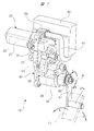
- FIG. 1 is a perspective view showing a rapid start prevention device according to the present invention
- FIG. 2 is a cross sectional view of a motor portion
- FIG. 3 is a perspective view explaining an internal structure of a gear portion
- FIG. The block diagram explaining a controller is shown, respectively.
- the sudden start prevention device 10 shown in FIG. 1 is mounted on a vehicle (not shown) that travels using either or both of an engine and an electric motor as a power source.
- This sudden start prevention device 10 is provided in the vicinity of the accelerator pedal 11 that controls the output of the power source, and applies a reaction force to the accelerator pedal 11 operated by the driver (operator) as necessary. It has become.
- the accelerator pedal 11 to which the reaction force is given by the sudden start prevention device 10 is rotatable in a predetermined angle range around a support shaft (not shown). Specifically, the side opposite to the support shaft side along the longitudinal direction of the accelerator pedal 11 is supported by the arm member 37 of the rapid start prevention device 10. The accelerator pedal 11 is held at the initial position shown in FIG. 1 by the biasing force of the return spring RS provided in the vicinity of the arm member 37 of the sudden start prevention device 10. The accelerator pedal 11 is configured to rotate within an angle range of about 30 ° from the initial position against the biasing force of the return spring RS by the driver's depression operation.
- the accelerator pedal 11 When the driver depresses the accelerator pedal 11, that is, when an operating force (depression force) of a predetermined magnitude is loaded on the accelerator pedal 11, the accelerator pedal 11 resists the urging force of the return spring RS and the pushing direction (arrow It is rotated in the direction a). When the accelerator pedal 11 is turned in the pushing direction, the output of the power source is increased according to the turning angle.
- the accelerator pedal 11 when the driver releases the depression on the accelerator pedal 11, that is, releases the load of the operating force on the accelerator pedal 11, the accelerator pedal 11 returns in the reverse direction to the pushing direction by the biasing force of the return spring RS. It is turned in the direction of arrow b and returns to the initial position. Then, as the accelerator pedal 11 pivots in the return direction, the output of the power source is reduced.
- the sudden start prevention device 10 operates to give a large reaction force to the accelerator pedal 11 when the accelerator pedal 11 is erroneously operated and the vehicle is suddenly started. Specifically, the arm member 37 of the rapid start prevention device 10 is pressed in the arrow c direction by the rotation of the accelerator pedal 11 in the pressing direction. At this time, for example, when the driver mistakenly presses the accelerator pedal 11 by mistake with the brake pedal and the rotation of the accelerator pedal 11 in the pushing direction increases rapidly, the sudden start prevention device 10 moves the arm member 37 in the arrow d direction. It is driven to transmit a large reaction force to the accelerator pedal 11.
- the sudden start prevention device 10 generates a reaction force larger than the pedaling force at this time, and the vehicle is suddenly started. Can be prevented.
- the sudden-start prevention device 10 includes a motor unit 20 and a gear unit 30.
- FIG. 2 shows a cross-sectional view of the motor unit 20 along the direction orthogonal to the axial direction of the armature shaft 26.
- illustration of the gear cover 32 is omitted.
- the motor unit 20 constitutes an actuator in the present invention, and includes a yoke 21 formed in a bottomed cylindrical shape by deep-drawing a steel plate.
- a pair of magnets 22 each having a substantially arc-shaped cross section is fixed to the radially inner side of the yoke 21.
- the magnets 22 are arranged opposite to each other (arranged by 180 °) about the axial center of the yoke 21.
- the armature 23 is rotatably accommodated inside the radial direction of each magnet 22 via a predetermined gap.
- the armature 23 includes a core 24 formed by laminating a plurality of steel plates, and eight slots 24 a are radially provided in the core 24.
- the coils 25 are wound around the eight slots 24a in a predetermined winding manner and number of turns.
- An armature shaft 26 is fixed at the rotation center of the core 24.
- a commutator 27 is fixed near the core 24 in the axial direction of the armature shaft 26.
- the commutator 27 is provided with eight commutator pieces 27a in accordance with the number of slots 24a.
- the commutator pieces 27a are hardened by the mold resin M to form an annular shape.
- the coils 25 wound around the slots 24a are electrically connected to the commutator pieces 27a.
- a pair of brushes 28 are in sliding contact with the outer peripheral portion of the commutator 27.
- the pair of brushes 28 are arranged opposite to each other (180 ° arrangement) with the commutator 27 at the center.
- Each brush 28 is movably held by a brush holder (not shown).
- the spring members 29 are disposed on the back side of the brushes 28, respectively, and the spring members 29 are configured to press the brushes 28 toward the commutator 27 with a predetermined pressure. Thereby, each brush 28 is in stable contact with the commutator 27.
- each spring member 29 is held by a spring holding portion (not shown) of the brush holder.
- the motor unit 20 is a brushed motor having a 2 pole 8 slot 2 brush structure. Then, by supplying a drive current to each brush 28, the coil 25 is energized through the commutator 27, and an electromagnetic force is generated in the core 24. Thereby, the armature shaft 26 is rotated at a predetermined rotational speed in a predetermined rotational direction.
- the brush holder for holding the brushes 28 is provided with a connector connection portion CN (see FIG. 1) to which the controller 40 (see FIG. 4) is electrically connected.
- a gear case 31 is fixed to the opening of the yoke 21.
- the gear case 31 is formed of an aluminum material or the like in a substantially bottomed bathtub shape, and a reduction gear mechanism SD including a plurality of gears is rotatably accommodated therein.
- the gear case 31 is closed by a gear cover 32 (see FIG. 1) which is also formed of an aluminum material or the like and formed substantially in a bottomed bathtub shape.
- the gear case 31 and the gear cover 32 which are abutted against each other form an outer shell of the gear portion 30.
- the return spring RS is provided between the gear cover 32 and the output shaft (rotational shaft) 36.
- the spring force of the return spring RS holds the position of the output shaft 36 relative to the gear cover 32 at the initial position shown in FIG.
- the tip end portion of the armature shaft 26 is disposed inside the gear case 31 and on the side of the yoke 21 along the longitudinal direction of the gear case 31 (left side in FIG. 3).
- a pinion gear 33 is fixed to the tip end portion of the armature shaft 26.
- the first double gear 34 includes a first large diameter gear 34 a meshed with the pinion gear 33 and a first small diameter gear 34 b smaller in diameter than the first large diameter gear 34 a.
- the pinion gear 33 and the first large diameter gear 34a form a first reduction gear.
- a second support shaft C2 made of a steel rod is provided inside the gear case 31 and on the opposite side of the pinion gear 33 along the longitudinal direction of the gear case 31 centering on the first support shaft C1.
- a second two-step gear 35 is rotatably supported by the second support shaft C2.
- the second double gear 35 includes a second large diameter gear 35a meshed with the first small diameter gear 34b and a second small diameter gear 35b smaller in diameter than the second large diameter gear 35a.
- the first small diameter gear 34 b and the second large diameter gear 35 a form a second reduction portion.
- a first ball bearing BB1 is mounted inside the gear case 31 and on the opposite side to the first support shaft C1 side along the longitudinal direction of the gear case 31 centering on the second support shaft C2.
- the first ball bearing BB1 rotatably supports the proximal end side of the output shaft 36.
- a second ball bearing BB2 similar to the first ball bearing BB1 is also mounted on the gear cover 32 side.
- the second ball bearing BB2 rotatably supports the tip end side of the output shaft 36.
- the base end of the arm member 37 is fixed by a nut N to the distal end side of the output shaft 36. That is, the arm member 37 is rotated together with the output shaft 36.
- a pedal support portion 37 a extending in a direction perpendicular to the extending direction of the arm member 37 is provided on the tip end side of the arm member 37.
- the pedal support portion 37 a supports the side opposite to the support shaft side along the longitudinal direction of the accelerator pedal 11.
- a rotation sensor 38 for detecting the rotation state of the output shaft 36 accompanying the operation of the accelerator pedal 11 is provided.
- the rotation sensor 38 constitutes an operation detection unit in the present invention, and detects an operation state of the accelerator pedal 11.
- the rotation sensor 38 is an annular sensor magnet fixed to the output shaft 36, and a plurality of Hall ICs fixed to the gear case 31 and arranged around the sensor magnet. , Is formed from.
- the controller 40 can grasp the rotation state (rotational speed etc.) of the output shaft 36 by counting the pulse signal from the Hall IC.
- the controller 40 compares the count value (integrated value) of the pulse signal from the Hall IC per unit time with the comparison threshold TH1 (see FIG. 4) stored in advance in the controller 40, and this comparison result It is determined on the basis of the rotational speed of the output shaft 36, that is, whether the driver mistakenly depresses the accelerator pedal 11 suddenly.
- the rotation sensor 38 provided on the output shaft 36 is not limited to the rotation sensor 38 including the sensor magnet and the Hall IC as described above, for example, an acceleration sensor capable of detecting an acceleration when the output shaft 36 tries to rotate. May be provided on the output shaft 36.
- the signal from the acceleration sensor can be used as it is for comparison, and as a result, the counting process of the pulse signal as described above becomes unnecessary. Therefore, the control load can be reduced and the control speed (reaction speed) by the controller 40 can be increased.
- any rotation sensor capable of detecting that the output shaft 36 is rapidly rotated can be used, and the form is not limited.
- an output gear 39 is provided at a substantially intermediate portion along the axial direction of the output shaft 36 via a one-way clutch and a torque limiter (neither of which is shown).
- the output gear 39 has a diameter larger than that of the second small diameter gear 35b, and is engaged with the second small diameter gear 35b.
- the second small diameter gear 35 b and the output gear 39 form a third reduction portion.
- the reduction gear mechanism SD having the first reduction gear portion to the third reduction gear portion is provided between the armature shaft 26 and the output shaft 36. It is designed to slow down. Therefore, the rapid start prevention device 10 is reduced in size, light in weight, and high in power, thereby suppressing an increase in size of the entire device.
- the one-way clutch provided on the output shaft 36 regulates the relative rotation of the output gear 39 in the clockwise direction (the direction of the arrow d in FIG. 1) with respect to the output shaft 36. It operates to allow relative rotation in the turning direction (the direction of arrow c in FIG. 1). That is, when torque is applied from the output shaft 36 to the output gear 39 in the clockwise direction, the output gear 39 is connected to the output shaft 36 to enable power transmission. In this state, the rapid start prevention device 10 is driven, and a large reaction force is transmitted to the accelerator pedal 11.
- This state is a state in which the arm member 37 (see FIG. 1) moved in the direction of the arrow c is automatically returned to the initial position regardless of the drive of the output shaft 36.
- the torque limiter idles when, for example, the driver strongly depresses the accelerator pedal 11 and the arm member 37 is loaded with a large stepping force, when the reduction mechanism SD bites in a foreign object and becomes unable to rotate. It is supposed to be. As a result, even if the sudden start prevention device 10 is in a failure state, an emergency accelerator operation can be performed by the driver's intention.
- the motor unit 20 that forms the sudden start prevention device 10 is controlled by the controller 40.
- the controller 40 is fixed almost directly beside the motor unit 20 via a bracket (not shown). That is, the controller 40 is integrally provided in the sudden-start prevention device 10, so that the vehicle can be easily retrofitted.
- a wire 41 electrically connecting the connector connection portion CN and the controller 40 is provided between the connector connection portion CN and the controller 40. More specifically, as shown in FIG. 4, the wiring 41 has a drive current A for driving the motor unit 20 and a motor monitoring current MA for grasping the drive state of the motor unit 20, The pulse signals PS from the rotation sensor 38 flow respectively.
- the controller 40 is provided with an erroneous operation determination unit 42, a drive current calculation unit 43, and a PWM drive circuit 44.
- the erroneous operation determination unit 42 constitutes a signal comparison unit in the present invention, and the pulse signal PS from the rotation sensor 38 (see shaded arrows in the drawing) is input to the erroneous operation determination unit 42. . Further, in the erroneous operation determination unit 42, a comparison threshold (threshold) TH1 set to a predetermined value is stored in advance. Then, the erroneous operation determination unit 42 executes a comparison process of comparing the count value (detection signal) CPS of the pulse signal PS per unit time with the comparison threshold TH1.
- the drive instruction signal (trigger signal) for driving the motor unit 20 from the erroneous operation determination unit 42 to the drive current calculation unit 43 S is output.
- the case where the comparison result in the erroneous operation determination unit 42 is “CPS ⁇ TH1” is the following case.
- the erroneous operation determination unit 42 determines that the accelerator pedal 11 has been erroneously operated.
- the misoperation determination unit 42 determines that the accelerator pedal 11 is normally operated.
- the drive current calculation unit 43 calculates a drive current A for driving the motor unit 20 with a predetermined drive torque Tq based on the input of the drive command signal S from the erroneous operation determination unit 42.
- the predetermined drive torque Tq is a large drive torque Tq for preventing the accelerator pedal 11 from being depressed further.
- the motor unit 20 is driven with a large driving torque Tq, and the accelerator pedal 11 is pushed back in the direction opposite to the operation direction, so that sudden start of the vehicle is prevented.
- the drive current calculation unit 43 adjusts the drive current A so as to intensify the drive torque Tq if it is determined that the drive torque Tq generated by the motor unit 20 is insufficient based on the motor monitor current MA. Conversely, if it is determined that the drive torque Tq generated by the motor unit 20 is excessive, the drive current A is adjusted to weaken the drive torque Tq. That is, the controller 40 executes feedback control (FB control) at a predetermined control cycle in order to drive the motor unit 20 with the driving torque Tq.
- FB control feedback control
- the motor unit 20 is driven by a drive current A which is subjected to duty control (PWM control) from the PWM drive circuit 44.
- PWM control duty control
- the controller 40 the motor unit 20 driven by the controller 40, and the rotation sensor 38 for detecting the operation state of the accelerator pedal 11
- an erroneous operation determination unit 42 which is provided in the controller 40 and stores the comparison threshold value TH1 to be compared with the count value CPS of the pulse signal PS from the rotation sensor 38.
- the motor unit 20 is driven to push back the accelerator pedal 11 in the direction opposite to the operation direction.
- the accelerator pedal 11 can be prevented from being operated erroneously without requiring various information (vehicle state signal) on the vehicle side, and sudden start of the vehicle can be suppressed. Therefore, complicated wiring work is not required, and retrofitting to existing vehicles is possible. In this case, regardless of the age of the vehicle, for example, it is possible to easily retrofit an old vehicle without electronic control.
- the output shaft 36 rotated by the operation of the accelerator pedal 11 is provided, and the output shaft 36 is a rotation that detects the rotation state of the output shaft 36 A sensor 38 is provided. Therefore, the sudden start prevention device 10 alone shown in FIG. 1 can detect an erroneous operation (a sudden depression operation) of the accelerator pedal 11 and prevent it. Therefore, retrofitting to a vehicle can be performed more easily.
- FIG. 5 is a view corresponding to FIG. 1 showing the sudden start prevention device of the second embodiment
- FIG. 6 is a view corresponding to FIG. 4 of the sudden start prevention device of FIG.
- an operation detection unit that detects the operation state of the accelerator pedal 11 as compared to the rapid-start prevention device 10 of the first embodiment.
- the rotation sensor 38 as the operation detection unit is provided on the proximal end side of the output shaft 36 and is incorporated in the rapid start prevention device 10.
- the depression force sensor 51 as an operation detection unit is provided on the surface of the accelerator pedal 11 outside the rapid start prevention device 50.
- the depression force sensor 51 detects the degree of depression of the accelerator pedal 11 by the driver, that is, the depression force of the driver, and is formed of a sheet-like piezoelectric element.
- the depression force sensor 51 When the driver erroneously operates the accelerator pedal 11 (depression force sensor 51) and sharply depresses the depression force F, the depression force sensor 51 outputs a large voltage signal ES.
- the depression force sensor 51 When the driver depresses the accelerator pedal 11 (depression force sensor 51) in a normal operation, the depression force sensor 51 outputs a small voltage signal ES.
- the wiring 52 of the pedal force sensor 51 is electrically connected to the controller 40.
- the voltage signal ES from the pedal force sensor 51 (see the hatched arrows in the drawing) is input to the erroneous operation determination unit 42.
- the erroneous operation determination unit 42 executes comparison processing of comparing the input voltage signal ES with the comparison threshold (threshold) TH2 set to a predetermined value.
- the drive instruction signal (trigger signal) for driving the motor unit 20 from the erroneous operation determination unit 42 to the drive current calculation unit 43 S is output.
- the misoperation determination unit 42 does not output the drive command signal S.
- the other control content is the same as that of the sudden start prevention device 10 of the first embodiment.
- the rapid start prevention device 50 and the pedal force sensor 51 are separate bodies. In other points, the same function and effect as those of the first embodiment can be obtained. Further, in the sudden start prevention device 50 of the second embodiment, since the voltage signal ES from the pedal force sensor 51 is used as it is, the control load can be reduced and the control speed (reaction speed) by the controller 40 can be increased.
- the pedal force sensor 51 is not limited to the sheet-like piezoelectric element provided on the surface of the accelerator pedal 11 as described above, but may be operated by operating the accelerator pedal 11 between the back surface of the accelerator pedal 11 and the floor of the vehicle.
- a load cell (load sensor) with straining strain gauges can also be arranged to accommodate.
- FIG. 7 shows a view corresponding to FIG. 4 showing the sudden start prevention device of the third embodiment.
- the controller 40 is mounted on a vehicle, which is a higher-level system.
- the controller 61 is connected.
- the controller 40 and the in-vehicle controller 61 can be easily connected to each other via, for example, a connector of "OBD 2 (On Board Diagnosis second generation)" standard used in a self-diagnosis function of a vehicle.
- the vehicle-side state signal that is, various state signals such as a throttle opening degree signal and a vehicle speed signal are input to the controller 40 from the onboard controller 61 through CAN communication.
- the controller 40 executes an interrupt process for prohibiting the operation of the rapid start prevention device 60 (hatching in the figure). See arrow). That is, when the vehicle is traveling, the output of the drive command signal (trigger signal) S for driving the motor unit 20 is prohibited even if the erroneous operation determination unit 42 determines that “CPS ⁇ TH1”. . As a result, the operation of the rapid start prevention device 60 (the drive of the motor unit 20) is prohibited, and the rapid depression of the accelerator pedal 11 is permitted. As a result, for example, passing on a freeway or the like can be easily performed.
- the sudden start prevention device 60 can also function as a “reaction force generating device” in order to receive a vehicle-side state signal from the onboard controller 61. Specifically, when the input throttle opening degree signal is large, the controller 40 drives the motor unit 20 to apply a reaction force to the accelerator pedal 11. Then, when the driver senses the reaction force from the sudden start prevention device 60, the driver can notice an excessive depression operation of the accelerator pedal 11, and in turn, can switch to traveling with an emphasis on fuel efficiency improvement.
- the same function and effect as those of the first embodiment described above can be obtained.
- the sudden-start prevention device 60 of the third embodiment since the vehicle-side state signal is received from the in-vehicle controller 61 by CAN communication, various more detailed control becomes possible.
- FIG. 8 is a view corresponding to FIG. 4 showing the sudden start prevention device of the fourth embodiment
- FIG. 9 is a view explaining the operation of the erroneous operation determination unit in the rapid start prevention device of FIG.
- the first motor unit (actuator) 80 is used in the sudden-start prevention device 70 of the fourth embodiment. It differs in that "high output type" was adopted. That is, the motor unit 80 generates a larger driving torque than the motor unit 20 (see FIG. 4) of the first embodiment.
- the second embodiment is different from the second embodiment in that a "one-step reduction gear" is adopted for the gear portion 90 in correspondence with the high output type motor portion 80.
- a "one-step reduction gear” is adopted for the gear portion 90 in correspondence with the high output type motor portion 80.
- the armature shaft of the motor unit 80 can be easily rotated by the operation of the accelerator pedal 11, and the sudden start is made according to the power generation amount of the motor unit 80 at this time.
- the prevention device 70 (motor unit 80) is driven. That is, the motor unit 80 in the power generation state constitutes the operation detection unit in the present invention.
- the motor unit 80 and the erroneous operation determination unit 42 are electrically connected to each other, and the generated voltage signal (detection signal) MV from the motor unit 80 is transmitted to the erroneous operation determination unit 42. It is supposed to be input. Then, the erroneous operation determination unit 42 performs a comparison process of comparing the input generated voltage signal MV with the comparison threshold TH3 stored in advance.
- the erroneous operation determination unit 42 is provided with a timer unit TM, and a comparison time ⁇ t set for a predetermined time (100 ms in the present embodiment) is stored in advance in the timer unit TM. Then, when the comparison result in the erroneous operation determination unit 42 is “MV ⁇ TH3”, the time measurement process (measurement) of the timer unit TM starts. After that, when it is determined that the time T when “MV ⁇ TH3” is equal to or longer than the comparison time (predetermined time) ⁇ t in the erroneous operation determination unit 42, the erroneous operation determination unit 42 directs the drive current calculation unit 43 to the motor. A drive command signal S for driving the unit 80 is output.
- the erroneous operation determination unit 42 outputs the drive command signal S toward the drive current calculation unit 43.
- the motor unit 80 is driven with a large drive torque Tq, and the accelerator pedal 11 is pushed back in the opposite direction to its operation direction, thereby preventing sudden start of the vehicle.
- the generated voltage signal MV changes gently, as shown by the broken line graph (normal operation) in FIG. That is, unlike an emergency braking operation, the driver depresses the accelerator pedal 11 gently. Therefore, the generated voltage signal MV at this time does not exceed the comparison threshold TH3, and the erroneous operation determination unit 42 can easily distinguish between the "incorrect operation” and the "normal operation".
- the accelerator pedal 11 is momentarily suddenly operated by hooking a foot on the accelerator pedal 11 or the like.
- the generated voltage signal MV instantaneously rises and exceeds the comparison threshold TH3 (triangular marks in the figure).
- the erroneous operation determination unit 42 is non-responsive to such "instant operation” and does not determine that it is an "incorrect operation”. Therefore, the motor unit 80 is not operated by the large driving torque Tq by the “instant operation”. In other words, the momentary operation of the accelerator pedal 11 effectively suppresses the unnecessary operation of the motor unit 80 with the large driving torque Tq.
- the erroneous operation determination unit 42 measures the time T during which the generated voltage signal MV is equal to or higher than the comparison threshold TH3, and the controller 40 determines the erroneous operation.
- the controller 40 determines the erroneous operation.
- the detection signal is the generated voltage signal MV.
- the pulse signal PS or the voltage signal is the same as in the first embodiment or the second embodiment.
- ES can also be used as a detection signal.
- the present invention is not limited to the above embodiments, and it goes without saying that various changes can be made without departing from the scope of the invention.
- the reduction gear mechanism is configured to obtain the reduction gear ratio as "three steps” or "one step”
- the present invention is not limited to this, and a motor unit with a larger output is provided.
- the (actuator) can be adopted to omit the reduction mechanism.
- the rotation sensor 38 for detecting the rotation state of the output shaft 36 and the pedal force sensor 51 for detecting the degree of depression of the accelerator pedal 11 are used as the operation detection unit.
- the invention is not limited to this, and for example, an acceleration sensor may be mounted on a control substrate (not shown) constituting the controller 40.
- the acceleration sensor mounted on the control substrate constitutes the operation detection unit in the present invention.
- the motor unit 20 as the actuator is a motor with a brush
- the present invention is not limited to this, and a brushless motor is adopted for the motor unit 20 as the actuator. It can also be done.
- the sudden start prevention device is used to prevent a sudden start of the vehicle due to an erroneous operation of the accelerator pedal.
Landscapes
- Engineering & Computer Science (AREA)
- Physics & Mathematics (AREA)
- General Physics & Mathematics (AREA)
- Automation & Control Theory (AREA)
- Chemical & Material Sciences (AREA)
- Combustion & Propulsion (AREA)
- Transportation (AREA)
- Mechanical Engineering (AREA)
- Auxiliary Drives, Propulsion Controls, And Safety Devices (AREA)
- Control Of Throttle Valves Provided In The Intake System Or In The Exhaust System (AREA)
- Mechanical Control Devices (AREA)
Abstract
コントローラ40と、コントローラ40により駆動されるモータ部20と、アクセルペダルの操作状態を検出する回転センサ38と、コントローラ40に設けられ、回転センサ38からのパルス信号PSのカウント値CPSと比較される比較しきい値TH1が格納された誤操作判断部42と、を備え、コントローラ40は、誤操作判断部42においてカウント値CPSが比較しきい値TH1以上であると判断されると、モータ部20を駆動してアクセルペダルをその操作方向とは逆方向に押し返す。
Description
本発明は、アクセルペダルの誤操作により車両が急発進するのを防止する急発進防止装置に関する。
例えば、特許文献1には、アクセルペダルの誤操作に起因した問題を解消するために、車両側の種々の情報(車両状態信号)を監視して、これに基づいてエンジンを強制的に停止させる等して、車両が急発進するのを防止するようにした急発進防止装置が記載されている。
また、特許文献2には、運転者(操作者)にアクセルペダルの操作状態を知らせる機能として、運転者のアクセルペダルの操作に対して反力を発生させる機能を備えた反力ペダル装置が記載されている。
しかしながら、上述の特許文献1および特許文献2に記載された技術では、既存の車両に急発進防止装置(新規システム)を後付けしようとする場合、車両に搭載された車載コントローラに、当該新規システムを割り込ませて構築する必要がある。この場合、車両の急発進に関する重要な信号を扱うため、間違えないように確実に配線する必要がある。すなわち、熟練した専門スタッフにより確実に配線作業を行う必要があり、よって、素人には容易に後付けできるシステムではなかった。
また、車両の設計時等においては、車載コントローラと新規システムとを協調させるために、車両側の制御内容(制御量等)を調整したり、あるいは新規システム側の制御内容(制御量等)を調整したりする必要があった。つまり、車両メーカと部品メーカとで、これらの調整をするのに比較的長い時間が必要となり、製品化までに時間が掛かるといった問題もあった。
本発明の目的は、車両側の種々の情報を必要とせず、既存の車両にも容易に後付けが可能な急発進防止装置を提供することにある。
本発明の一態様では、アクセルペダルの誤操作により車両が急発進するのを防止する急発進防止装置であって、コントローラと、前記コントローラにより駆動されるアクチュエータと、前記アクセルペダルの操作状態を検出する操作検出部と、前記コントローラに設けられ、前記操作検出部からの検出信号と比較されるしきい値が格納された信号比較部と、を備え、前記コントローラは、前記信号比較部において前記検出信号が前記しきい値以上であると判断されると、前記アクチュエータを駆動して前記アクセルペダルをその操作方向とは逆方向に押し返す。
本発明の他の態様では、前記アクセルペダルの操作により回転される回転軸を有し、前記操作検出部が前記回転軸の回転状態を検出する回転センサである。
本発明の他の態様では、前記操作検出部が、前記アクセルペダルに設けられ、操作者の踏力を検出する踏力センサである。
本発明の他の態様では、前記コントローラに、前記車両に搭載された車載コントローラが接続され、前記コントローラは、前記車載コントローラからの前記車両が走行中であることを示す走行信号の入力に基づき、前記アクチュエータの駆動を禁止する。
本発明の他の態様では、前記信号比較部は、前記検出信号が前記しきい値以上となっている時間を計測し、前記コントローラは、前記信号比較部において前記検出信号が前記しきい値以上であると判断され、かつ前記時間が所定時間以上であると判断されると、前記アクチュエータを駆動して前記アクセルペダルをその操作方向とは逆方向に押し返す。
本発明によれば、コントローラと、コントローラにより駆動されるアクチュエータと、アクセルペダルの操作状態を検出する操作検出部と、コントローラに設けられ、操作検出部からの検出信号と比較されるしきい値が格納された信号比較部と、を備え、コントローラは、信号比較部において検出信号がしきい値以上であると判断されると、アクチュエータを駆動してアクセルペダルをその操作方向とは逆方向に押し返す。
これにより、車両側の種々の情報(車両状態信号)を必要とせずに、アクセルペダルが誤操作されるのを防止して、車両の急発進を抑えることができる。よって、複雑な配線作業が不要となり、既存の車両に容易に後付けが可能となる。この場合、車両の年式は関係無く、例えば、電子制御が無かった頃の古い車両にも容易に後付けが可能となる。
以下、本発明の実施の形態1について、図面を用いて詳細に説明する。
図1は本発明に係る急発進防止装置を示す斜視図を、図2はモータ部の断面図を、図3はギヤ部の内部構造を説明する斜視図を、図4は急発進防止装置のコントローラを説明するブロック図をそれぞれ示している。
図1に示される急発進防止装置10は、エンジンと電動モータのうちのいずれか一方または双方を動力源として走行する車両(図示せず)に搭載されるものである。この急発進防止装置10は、動力源の出力をコントロールするアクセルペダル11の近傍に設けられ、運転者(操作者)により操作されるアクセルペダル11に対して、必要に応じて反力を与えるようになっている。
急発進防止装置10によって反力が与えられるアクセルペダル11は、支軸(図示せず)を中心に所定の角度範囲で回動自在となっている。具体的には、アクセルペダル11の長手方向に沿う支軸側とは反対側が、急発進防止装置10のアーム部材37によって支持されている。そして、アクセルペダル11は、急発進防止装置10のアーム部材37の近傍に設けられたリターンスプリングRSの付勢力により、図1に示される初期位置に保持されている。アクセルペダル11は、運転者の踏み込み操作により、リターンスプリングRSの付勢力に抗して、初期位置から約30°の角度範囲で回動するようになっている。
運転者によってアクセルペダル11が踏み込まれると、つまりアクセルペダル11に所定の大きさの操作力(踏力)が負荷されると、アクセルペダル11はリターンスプリングRSの付勢力に抗して押し方向(矢印a方向)に回動される。アクセルペダル11が押し方向に回動されると、その回動角度に応じて動力源の出力が増大するようになっている。
これに対し、運転者がアクセルペダル11に対する踏み込みを解除、つまりアクセルペダル11への操作力の負荷を解除すると、アクセルペダル11はリターンスプリングRSの付勢力により、押し方向とは逆向きの戻し方向(矢印b方向)に回動されて初期位置に戻る。そして、アクセルペダル11の戻し方向への回動に伴って、動力源の出力が減少される。
急発進防止装置10は、アクセルペダル11が誤操作されて車両が急発進されるようなときに、アクセルペダル11に大きな反力を与えるように作動する。具体的には、急発進防止装置10のアーム部材37は、アクセルペダル11の押し方向への回動により矢印c方向に押圧される。このとき、例えば、運転者がブレーキペダルと間違えてアクセルペダル11を踏み込み、アクセルペダル11の押し方向への回動が急激に増加すると、急発進防止装置10は、アーム部材37を矢印d方向に駆動して、アクセルペダル11に大きな反力を伝達する。
これにより、運転者の誤操作(不注意)によりアクセルペダル11が急激に踏み込まれたとしても、このときの踏力よりも大きな反力を急発進防止装置10が発生して、車両が急発進されるのを防止することができる。
図1ないし図3に示されるように、急発進防止装置10は、モータ部20とギヤ部30とを備えている。ここで、図2は、アーマチュア軸26の軸方向と直交する方向に沿うモータ部20の断面図を示している。また、図3においては、ギヤ部30の内部構造を判り易くするために、ギヤカバー32の図示を省略している。
モータ部20は、本発明におけるアクチュエータを構成しており、鋼板を深絞り加工等することで有底筒状に形成されたヨーク21を備えている。ヨーク21の径方向内側には、断面が略円弧形状に形成された一対のマグネット22が固定されている。これらのマグネット22は、ヨーク21の軸心を中心に、対向配置(180°配置)されている。
各マグネット22の径方向内側には、所定の隙間を介してアーマチュア23が回転自在に収容されている。アーマチュア23は、複数の鋼板を積層してなるコア24を備えており、コア24には、8つのスロット24aが放射状に設けられている。そして、8つのスロット24aには、所定の巻き方および巻き数でコイル25が巻装されている。
コア24の回転中心には、アーマチュア軸26が固定されている。アーマチュア軸26の軸方向に沿うコア24の近傍には、コンミテータ27が固定されている。コンミテータ27は、スロット24aの数に合わせて8つのコンミテータ片27aを備えている。これらのコンミテータ片27aは、モールド樹脂Mにより環状をなすよう固められている。そして、コンミテータ片27aのそれぞれには、スロット24aに巻装されたコイル25が電気的に接続されている。
コンミテータ27の外周部分には、一対のブラシ28が摺接するようになっている。一対のブラシ28は、コンミテータ27を中心に、対向配置(180°配置)されている。なお、各ブラシ28は、図示しないブラシホルダに移動自在に保持されている。そして、各ブラシ28の背面側には、ばね部材29がそれぞれ配置され、各ばね部材29は、各ブラシ28をコンミテータ27に向けて、所定圧で押圧するようになっている。これにより、各ブラシ28は、コンミテータ27に対して安定して接触される。ここで、各ばね部材29は、ブラシホルダのスプリング保持部(図示せず)に保持されている。
このように、モータ部20は、2極8スロット2ブラシ構造のブラシ付きモータとなっている。そして、各ブラシ28に駆動電流を供給することで、コンミテータ27を介してコイル25が通電されて、コア24に電磁力が発生する。これにより、アーマチュア軸26が所定の回転方向に所定の回転速度で回転される。なお、各ブラシ28を保持するブラシホルダには、コントローラ40(図4参照)が電気的に接続されるコネクタ接続部CN(図1参照)が設けられている。
図3に示されるように、ヨーク21の開口部分には、ギヤケース31が固定されている。ギヤケース31は、アルミ材料等により有底の略バスタブ形状に形成され、その内部には複数の歯車よりなる減速機構SDが回転自在に収容されている。そして、ギヤケース31は、同じくアルミ材料等により有底の略バスタブ形状に形成されたギヤカバー32(図1参照)により閉塞されている。なお、互いに突き合わされたギヤケース31およびギヤカバー32は、ギヤ部30の外郭を形成している。
ここで、リターンスプリングRSは、ギヤカバー32と出力軸(回転軸)36との間に設けられている。そして、リターンスプリングRSのばね力は、ギヤカバー32に対する出力軸36の位置を、図1に示される初期位置に保持するようになっている。
ギヤケース31の内部で、かつギヤケース31の長手方向に沿うヨーク21側(図3中左側)には、アーマチュア軸26の先端部分が配置されている。そして、アーマチュア軸26の先端部分には、ピニオンギヤ33が固定されている。
また、ギヤケース31の内部で、かつアーマチュア軸26の近傍には、鋼棒よりなる第1支軸C1が設けられ、第1支軸C1には、第1の二段ギヤ34が回転自在に支持されている。第1の二段ギヤ34は、ピニオンギヤ33に噛み合わされる第1大径歯車34aと、第1大径歯車34aよりも小径の第1小径歯車34bとを備えている。ここで、ピニオンギヤ33および第1大径歯車34aは、第1減速部を形成している。
ギヤケース31の内部で、かつ第1支軸C1を中心としたギヤケース31の長手方向に沿うピニオンギヤ33側とは反対側には、鋼棒よりなる第2支軸C2が設けられている。この第2支軸C2には、第2の二段ギヤ35が回転自在に支持されている。第2の二段ギヤ35は、第1小径歯車34bに噛み合わされる第2大径歯車35aと、第2大径歯車35aよりも小径の第2小径歯車35bとを備えている。ここで、第1小径歯車34bおよび第2大径歯車35aは、第2減速部を形成している。
ギヤケース31の内部で、かつ第2支軸C2を中心としたギヤケース31の長手方向に沿う第1支軸C1側とは反対側には、第1ボールベアリングBB1が装着されている。この第1ボールベアリングBB1は、出力軸36の基端側を回転自在に支持している。なお、ギヤカバー32側にも、第1ボールベアリングBB1と同様の第2ボールベアリングBB2が装着されている。この第2ボールベアリングBB2は、出力軸36の先端側を回転自在に支持している。
また、出力軸36の先端側には、図1に示されるように、アーム部材37の基端部がナットNによって固定されている。つまり、アーム部材37は、出力軸36とともに回転される。そして、アーム部材37の先端側には、アーム部材37の延在方向と直交する方向に延びるペダル支持部37aが設けられている。このペダル支持部37aは、アクセルペダル11の長手方向に沿う支軸側とは反対側を支持している。
さらに、出力軸36の基端側には、アクセルペダル11の操作に伴う出力軸36の回転状態を検出する回転センサ38(図1参照)が設けられている。ここで、回転センサ38は、本発明における操作検出部を構成しており、アクセルペダル11の操作状態を検出するものである。具体的には、回転センサ38は、詳細には図示しないが、出力軸36に固定された環状のセンサマグネットと、ギヤケース31に固定され、かつセンサマグネットの周囲に配置された複数のホールICと、から形成されている。これにより、コントローラ40は、ホールICからのパルス信号をカウントすることで、出力軸36の回転状態(回転速度等)を把握することができる。
ここで、本実施の形態の急発進防止装置10では、運転者によるアクセルペダル11の踏み込み速度を検知して、これを誤操作防止の制御に利用している。よって、コントローラ40は、単位時間当たりのホールICからのパルス信号のカウント値(積算値)と、コントローラ40に予め格納された比較しきい値TH1(図4参照)とを比較し、この比較結果に基づいて、出力軸36の回転速度、つまり運転者が誤ってアクセルペダル11を急激に踏み込んでいるか否かを判断する。
ただし、出力軸36に設ける回転センサ38としては、上述のようなセンサマグネットおよびホールICよりなる回転センサ38に限らず、例えば、出力軸36が回転しようとするときの加速度を検知し得る加速度センサを、出力軸36に設けても良い。この場合、加速度センサからの信号をそのまま比較に用いることができ、ひいては上述のようなパルス信号のカウント処理が不要となる。よって、制御負荷を軽減してコントローラ40による制御速度(反応速度)を上げることが可能となる。それ以外にも、出力軸36が急激に回転されることを検知可能な回転センサであれば利用可能であって、その形式は問わない。
また、出力軸36の軸方向に沿う略中間部分には、ワンウェイクラッチおよびトルクリミッタ(何れも図示せず)を介して、出力歯車39が設けられている。出力歯車39は、第2小径歯車35bよりも大径とされ、第2小径歯車35bに噛み合わされている。ここで、第2小径歯車35bおよび出力歯車39は、第3減速部を形成している。
このように、本実施の形態の急発進防止装置10では、アーマチュア軸26と出力軸36との間に、第1減速部から第3減速部を有する減速機構SDを備えており、三段の減速を行うようになっている。したがって、急発進防止装置10を小型軽量かつ高出力型として、その全体が大型化されるのを抑制している。
ここで、出力軸36に設けられるワンウェイクラッチは、出力軸36に対する出力歯車39の時計回り方向(図1の矢印d方向)への相対回転を規制し、出力軸36に対する出力歯車39の反時計回り方向(図1の矢印c方向)への相対回転を許容するよう作動する。すなわち、出力軸36から出力歯車39に対して時計回り方向に付勢するトルクが加わると、出力歯車39は出力軸36に対して接続状態となって動力伝達が可能となる。この状態は、急発進防止装置10が駆動されて、アクセルペダル11に大きな反力が伝達されている状態である。
これに対し、出力歯車39から出力軸36に対して反時計回り方向に付勢するトルクが加わると、出力歯車39は出力軸36から切断されて遮断状態となり、互いに動力伝達されなくなる。この状態は、矢印c方向に移動されたアーム部材37(図1参照)が、出力軸36の駆動に依らず、初期位置に自動的に復帰されるときの状態である。
また、トルクリミッタは、例えば、減速機構SDが異物を噛み込んで回転不能となった場合において、運転者がアクセルペダル11を強く踏み込み、アーム部材37に大きな踏力が負荷されたときに、空転するようになっている。これにより、急発進防止装置10が故障状態になっても、運転者の意思による緊急のアクセル操作が可能となる。
図4に示されるように、急発進防止装置10を形成するモータ部20は、コントローラ40により制御される。コントローラ40は、図1に示されるように、モータ部20の略真横にブラケット(図示せず)を介して固定されている。すなわち、急発進防止装置10には、コントローラ40が一体に設けられており、車両への後付けを容易に行うことができる。
図1に示されるように、コネクタ接続部CNとコントローラ40との間には、両者を電気的に接続する配線41が設けられている。より具体的には、配線41には、図4に示されるように、モータ部20を駆動するための駆動電流Aと、モータ部20の駆動状態を把握するためのモータ部監視電流MAと、回転センサ38からのパルス信号PSと、がそれぞれ流れるようになっている。
そして、コントローラ40には、誤操作判断部42と、駆動電流算出部43と、PWM駆動回路44と、が設けられている。
誤操作判断部42は、本発明における信号比較部を構成しており、この誤操作判断部42には、回転センサ38からのパルス信号PS(図中網掛矢印参照)が入力されるようになっている。また、誤操作判断部42には、所定値に設定された比較しきい値(しきい値)TH1が予め格納されている。そして、誤操作判断部42では、単位時間当たりのパルス信号PSのカウント値(検出信号)CPSと、比較しきい値TH1と、を比較する比較処理が実行される。
誤操作判断部42での比較結果が「CPS≧TH1」であった場合には、誤操作判断部42から駆動電流算出部43に向けて、モータ部20を駆動させるための駆動指令信号(トリガ信号)Sが出力される。具体的には、誤操作判断部42での比較結果が「CPS≧TH1」の場合とは、以下のような場合である。
すなわち、運転者がアクセルペダル11(図1参照)を誤って急激に踏み込むと、出力軸36が急激に回転されてその回転数ORが急激に増加する。すると、回転センサ38からのパルス信号PSの単位時間当たりのカウント値CPSが急増する。よって、単位時間当たりのカウント値CPSが、比較しきい値TH1以上となる。これにより、誤操作判断部42は、アクセルペダル11が誤操作されたと判断する。
これに対し、誤操作判断部42での比較結果が「CPS<TH1」であった場合には、誤操作判断部42からは、駆動指令信号Sが出力されない。したがって、モータ部20は停止されたままで駆動されない。つまり、運転者がアクセルペダル11を通常操作した場合には、出力軸36の回転数ORは低い状態となる。よって、回転センサ38からのパルス信号PSの単位時間当たりのカウント値CPSは小さい値を示す。これにより、誤操作判断部42は、アクセルペダル11が通常操作されたと判断する。
駆動電流算出部43では、誤操作判断部42からの駆動指令信号Sの入力に基づいて、モータ部20を所定の駆動トルクTqで駆動するための駆動電流Aを算出する。ここで、所定の駆動トルクTqとは、アクセルペダル11をそれ以上踏み込ませないようにするための大きな駆動トルクTqである。これにより、モータ部20が大きな駆動トルクTqで駆動されて、アクセルペダル11がその操作方向とは逆方向に押し返されて、車両の急発進が防止される。
また、駆動電流算出部43には、モータ部20が指示通りの駆動トルクTqを発生しているか否かを監視するために、モータ部20に流れている現在の電流(モータ部監視電流MA)が入力される。そして、駆動電流算出部43では、モータ部監視電流MAに基づいて、モータ部20が発生する駆動トルクTqが足りないと判断すると、駆動トルクTqを強めるよう駆動電流Aを調整する。これとは逆に、モータ部20が発生する駆動トルクTqが過剰であると判断すると、駆動トルクTqを弱めるよう駆動電流Aを調整する。つまり、コントローラ40は、モータ部20を駆動トルクTqで駆動するために、所定の制御周期でフィードバック制御(FB制御)を実行している。
また、モータ部20は、PWM駆動回路44からのデューティー制御(PWM制御)された駆動電流Aにより駆動されるようになっている。このように、モータ部20を、デューティー制御された駆動電流Aで駆動することにより、コントローラ40の全体の発熱が抑えられて、コントローラ40の高効率化が図られている。
以上詳述したように、本実施の形態に係る急発進防止装置10によれば、コントローラ40と、コントローラ40により駆動されるモータ部20と、アクセルペダル11の操作状態を検出する回転センサ38と、コントローラ40に設けられ、回転センサ38からのパルス信号PSのカウント値CPSと比較される比較しきい値TH1が格納された誤操作判断部42と、を備え、コントローラ40は、誤操作判断部42においてカウント値CPSが比較しきい値TH1以上であると判断されると、モータ部20を駆動してアクセルペダル11をその操作方向とは逆方向に押し返す。
これにより、車両側の種々の情報(車両状態信号)を必要とせずに、アクセルペダル11が誤操作されるのを防止して、車両の急発進を抑えることができる。よって、複雑な配線作業が不要となり、既存の車両に容易に後付けが可能となる。この場合、車両の年式は関係無く、例えば、電子制御が無かった頃の古い車両にも容易に後付けが可能となる。
また、本実施の形態に係る急発進防止装置10によれば、アクセルペダル11の操作により回転される出力軸36を有し、当該出力軸36には、出力軸36の回転状態を検出する回転センサ38が設けられている。よって、図1に示される急発進防止装置10単体で、アクセルペダル11の誤操作(急激な踏み込み操作)を検知して、それを防止することができる。したがって、車両への後付けをより容易に行うことができる。
次に、本発明の実施の形態2について、図面を用いて詳細に説明する。なお、上述した実施の形態1と同一の機能を有する部分については同一の記号を付し、その詳細な説明を省略する。
図5は実施の形態2の急発進防止装置を示す図1に対応した図を、図6は図5の急発進防止装置の図4に対応した図をそれぞれ示している。
図5および図6に示されるように、実施の形態2の急発進防止装置50では、実施の形態1の急発進防止装置10に比して、アクセルペダル11の操作状態を検出する操作検出部のみが異なっている。具体的には、実施の形態1の急発進防止装置10では、操作検出部としての回転センサ38を、出力軸36の基端側に設け、急発進防止装置10に内蔵していた。これに対し、実施の形態2の急発進防止装置50では、操作検出部としての踏力センサ51を、急発進防止装置50の外部にあるアクセルペダル11の表面に設けている。
踏力センサ51は、運転者によるアクセルペダル11の踏み込み具合、つまり、運転者の踏力を検出するものであって、シート状の圧電素子により形成されている。そして、運転者がアクセルペダル11(踏力センサ51)を誤操作して、踏力Fで急激に強く踏み込むと、踏力センサ51からは大きな電圧信号ESが出力される。これに対し、運転者がアクセルペダル11(踏力センサ51)を通常操作で踏み込むと、踏力センサ51からは小さな電圧信号ESが出力される。
図5に示されるように、踏力センサ51の配線52は、コントローラ40に電気的に接続されている。これにより、図6に示されるように、踏力センサ51からの電圧信号ES(図中網掛矢印参照)が、誤操作判断部42に入力される。そして、誤操作判断部42では、入力された電圧信号ESと、所定値に設定された比較しきい値(しきい値)TH2と、を比較する比較処理が実行される。
誤操作判断部42での比較結果が「ES≧TH2」であった場合には、誤操作判断部42から駆動電流算出部43に向けて、モータ部20を駆動させるための駆動指令信号(トリガ信号)Sが出力される。これに対し、誤操作判断部42での比較結果が「ES<TH2」であった場合には、誤操作判断部42からは、駆動指令信号Sが出力されない。その他の制御内容は、実施の形態1の急発進防止装置10と同様である。
以上のように形成した実施の形態2の急発進防止装置50においては、急発進防止装置50と踏力センサ51とが別体となっている。その他の点においては、上述した実施の形態1と同様の作用効果を奏することができる。また、実施の形態2の急発進防止装置50では、踏力センサ51からの電圧信号ESをそのまま用いるため、制御負荷を軽減してコントローラ40による制御速度(反応速度)を上げることが可能となる。
なお、踏力センサ51としては、上述のようなアクセルペダル11の表面に設けられるシート状の圧電素子に限らず、アクセルペダル11の裏面と車両の床面との間に、アクセルペダル11の操作により歪むひずみゲージを備えたロードセル(荷重センサ)を配置して対応することもできる。
次に、本発明の実施の形態3について、図面を用いて詳細に説明する。なお、上述した実施の形態1と同一の機能を有する部分については同一の記号を付し、その詳細な説明を省略する。
図7は実施の形態3の急発進防止装置を示す図4に対応した図を示している。
図7に示されるように、実施の形態3の急発進防止装置60では、実施の形態1の急発進防止装置10に比して、コントローラ40に、その上位システムである車両に搭載された車載コントローラ61が接続されている点が異なっている。具体的には、コントローラ40と車載コントローラ61とは、例えば、車両の自己診断機能で用いられる「OBD2(On Board Diagnosis second generation)」規格のコネクタを介して、互いに容易に接続可能となっている。そして、コントローラ40には、車載コントローラ61からCAN通信により、車両側の状態信号、つまりスロットル開度信号や車速信号等の種々の状態信号が入力されるようになっている。
コントローラ40は、車載コントローラ61から車両が走行中であることを示す車速信号(走行信号)Vが入力されると、急発進防止装置60の動作を禁止する割り込み処理が実行される(図中ハッチング矢印参照)。すなわち、車両が走行中である場合には、誤操作判断部42において「CPS≧TH1」と判断されても、モータ部20を駆動させるための駆動指令信号(トリガ信号)Sの出力が禁止される。これにより、急発進防止装置60の作動(モータ部20の駆動)が禁止されて、アクセルペダル11の急激な踏み込み動作が許容される。これにより、例えば、高速道路等での追い越しを容易に行うことが可能となる。
また、急発進防止装置60は、車載コントローラ61から車両側の状態信号を受け取るため「反力発生装置」として機能させることもできる。具体的には、コントローラ40は、入力されたスロットル開度信号が大きい場合に、モータ部20を駆動させて、アクセルペダル11に反力を与える。そして、急発進防止装置60からの反力を運転者が感じ取ることで、運転者はアクセルペダル11の過剰な踏み込み操作に気付き、ひいては燃費向上重視の走行に切り換えることが可能となる。
以上のように形成した実施の形態3の急発進防止装置60においても、上述した実施の形態1と同様の作用効果を奏することができる。これに加えて、実施の形態3の急発進防止装置60では、車載コントローラ61からCAN通信により車両側の状態信号を受け取るため、よりきめ細かい種々の制御が可能となる。
次に、本発明の実施の形態4について、図面を用いて詳細に説明する。なお、上述した実施の形態1と同一の機能を有する部分については同一の記号を付し、その詳細な説明を省略する。
図8は実施の形態4の急発進防止装置を示す図4に対応した図を、図9は図4の急発進防止装置における誤操作判断部の動作を説明する図をそれぞれ示している。
図8に示されるように、実施の形態4の急発進防止装置70では、実施の形態1の急発進防止装置10(図4参照)に比して、第1にモータ部(アクチュエータ)80に「高出力型」を採用した点が異なっている。つまり、モータ部80は、実施の形態1のモータ部20(図4参照)よりも大きな駆動トルクを発生するようになっている。
また、高出力型のモータ部80に対応させて、第2にギヤ部90に「一段減速機」を採用した点が異なっている。これにより、ギヤ部90を形成する減速機構(図示せず)の減速比を小さくして、アクセルペダル11(図1参照)の操作によりモータ部80のアーマチュア軸(図示せず)を容易に回転可能としている。
このように、実施の形態4の急発進防止装置70では、アクセルペダル11の操作により、モータ部80のアーマチュア軸を容易に回転可能として、このときのモータ部80の発電量に応じて急発進防止装置70(モータ部80)を駆動させるようにしている。つまり、発電状態にあるモータ部80が、本発明における操作検出部を構成している。
具体的には、図8に示されるように、モータ部80と誤操作判断部42とは互いに電気的に接続され、モータ部80からの発電電圧信号(検出信号)MVが、誤操作判断部42に入力されるようになっている。そして、誤操作判断部42では、入力された発電電圧信号MVと、予め格納された比較しきい値TH3と、を比較する比較処理を実行する。
また、誤操作判断部42にはタイマー部TMが設けられ、当該タイマー部TMには、所定時間(本実施の形態では100ms)に設定された比較時間δtが予め格納されている。そして、誤操作判断部42での比較結果が「MV≧TH3」の場合に、タイマー部TMの計時処理(計測)がスタートする。その後、誤操作判断部42において「MV≧TH3」となっている時間Tが比較時間(所定時間)δt以上であると判断されると、誤操作判断部42から駆動電流算出部43に向けて、モータ部80を駆動させるための駆動指令信号Sが出力される。
より具体的には、図9の実線グラフ(誤操作)に示されるように、時間t1において、運転者がアクセルペダル11を誤って急激に踏み込むと、出力軸36が急激に回転されてその回転数ORが急激に増加する。すると、モータ部80からの発電電圧信号MVが急増する。このとき、緊急時のブレーキ操作と同様の踏力でアクセルペダル11を勢い良く踏み込むため、発電電圧信号MVは、比較しきい値TH3を大きく上回ることになる(図中丸印部分)。
その後、δt(100ms)が経過した時間t2(図中星印部分)において、誤操作判断部42は駆動電流算出部43に向けて駆動指令信号Sを出力する。これにより、誤操作の後でかつδtが経過した後に、モータ部80が大きな駆動トルクTqで駆動され、アクセルペダル11がその操作方向とは逆方向に押し返されて、車両の急発進が防止される。
なお、通常のアクセルペダル11の操作時には、図9の破線グラフ(通常操作)に示されるように、緩やかに発電電圧信号MVは変化する。つまり、緊急時のブレーキ操作とは異なり、運転者は緩やかにアクセルペダル11を踏み込む。よって、このときの発電電圧信号MVは比較しきい値TH3を越えることが無く、誤操作判断部42は、「誤操作」と「通常操作」とを容易に識別することが可能となっている。
また、例えば、運転者が緊急時のブレーキ操作の際に、アクセルペダル11に足を引っ掛ける等して、アクセルペダル11が瞬間的に急激に操作されたような場合には、図9の一点鎖線グラフ(瞬間操作)に示されるように、瞬間的に発電電圧信号MVが立ち上がり、かつ比較しきい値TH3を越えるようなことが起こり得る(図中三角印部分)。このような「瞬間操作」に対しては、誤操作判断部42は無反応であって、「誤操作」と判断することが無い。よって、「瞬間操作」によりモータ部80を大きな駆動トルクTqで動作させることは無い。言い換えれば、瞬間的なアクセルペダル11の操作により、無用にモータ部80が大きな駆動トルクTqで動作されるようなことが効果的に抑えられる。
以上のように形成した実施の形態4の急発進防止装置70においても、上述した実施の形態1と同様の作用効果を奏することができる。これに加えて、実施の形態4の急発進防止装置70では、誤操作判断部42は、発電電圧信号MVが比較しきい値TH3以上となっている時間Tを計測し、コントローラ40は、誤操作判断部42において発電電圧信号MVが比較しきい値TH3以上であると判断され、かつ時間Tが比較時間δt以上であると判断されると、モータ部80を駆動してアクセルペダル11をその操作方向とは逆方向に押し返す。したがって、瞬間的なアクセルペダル11の操作(瞬間操作)により、無用にモータ部80が大きな駆動トルクTqで動作されるようなことを効果的に抑えることができる。
なお、実施の形態4において、検出信号を発電電圧信号MVとしたものを示したが、当該発電電圧信号MVに換えて、実施の形態1や実施の形態2と同様にパルス信号PSや電圧信号ESを検出信号に用いることもできる。
本発明は上記各実施の形態に限定されるものではなく、その要旨を逸脱しない範囲で種々変更可能であることは言うまでもない。例えば、上記各実施の形態では、減速機構SDを「三段」や「一段」として減速比が得られるようにしたものを示したが、本発明はこれに限らず、さらに出力の大きいモータ部(アクチュエータ)を採用して減速機構を省略することもできる。
また、上記各実施の形態では、操作検出部として、出力軸36の回転状態を検出する回転センサ38や、アクセルペダル11の踏み込み具合を検出する踏力センサ51を採用したものを示したが、本発明はこれに限らず、例えば、コントローラ40を構成する制御基板(図示せず)に、加速度センサを実装させても構わない。これにより、車両の急発進を検出して、迅速に急発進防止装置を駆動させることができる。この場合、制御基板に実装された加速度センサが、本発明における操作検出部を構成することになる。
さらに、上記各実施の形態では、アクチュエータとしてのモータ部20を、ブラシ付きのモータとしたものを示したが、本発明はこれに限らず、アクチュエータとしてのモータ部20に、ブラシレスモータを採用することもできる。
その他、上記各実施の形態における各構成要素の材質,形状,寸法,数,設置箇所等は、本発明を達成できるものであれば任意であり、上記各実施の形態に限定されない。
急発進防止装置は、アクセルペダルの誤操作により車両が急発進するのを防止するために用いられる。
Claims (5)
- アクセルペダルの誤操作により車両が急発進するのを防止する急発進防止装置であって、
コントローラと、
前記コントローラにより駆動されるアクチュエータと、
前記アクセルペダルの操作状態を検出する操作検出部と、
前記コントローラに設けられ、前記操作検出部からの検出信号と比較されるしきい値が格納された信号比較部と、
を備え、
前記コントローラは、前記信号比較部において前記検出信号が前記しきい値以上であると判断されると、前記アクチュエータを駆動して前記アクセルペダルをその操作方向とは逆方向に押し返す、
急発進防止装置。 - 請求項1記載の急発進防止装置において、
前記アクセルペダルの操作により回転される回転軸を有し、前記操作検出部が前記回転軸の回転状態を検出する回転センサである、
急発進防止装置。 - 請求項1記載の急発進防止装置において、
前記操作検出部が、前記アクセルペダルに設けられ、操作者の踏力を検出する踏力センサである、
急発進防止装置。 - 請求項1記載の急発進防止装置において、
前記コントローラに、前記車両に搭載された車載コントローラが接続され、
前記コントローラは、前記車載コントローラからの前記車両が走行中であることを示す走行信号の入力に基づき、前記アクチュエータの駆動を禁止する、
急発進防止装置。 - 請求項1記載の急発進防止装置において、
前記信号比較部は、前記検出信号が前記しきい値以上となっている時間を計測し、
前記コントローラは、前記信号比較部において前記検出信号が前記しきい値以上であると判断され、かつ前記時間が所定時間以上であると判断されると、前記アクチュエータを駆動して前記アクセルペダルをその操作方向とは逆方向に押し返す、
急発進防止装置。
Priority Applications (2)
| Application Number | Priority Date | Filing Date | Title |
|---|---|---|---|
| EP18834894.0A EP3656596A4 (en) | 2017-07-20 | 2018-05-08 | DEVICE TO PREVENT SUDDEN START |
| JP2019530890A JPWO2019017041A1 (ja) | 2017-07-20 | 2018-05-08 | 急発進防止装置 |
Applications Claiming Priority (2)
| Application Number | Priority Date | Filing Date | Title |
|---|---|---|---|
| JP2017-140421 | 2017-07-20 | ||
| JP2017140421 | 2017-07-20 |
Publications (1)
| Publication Number | Publication Date |
|---|---|
| WO2019017041A1 true WO2019017041A1 (ja) | 2019-01-24 |
Family
ID=65015075
Family Applications (1)
| Application Number | Title | Priority Date | Filing Date |
|---|---|---|---|
| PCT/JP2018/017723 Ceased WO2019017041A1 (ja) | 2017-07-20 | 2018-05-08 | 急発進防止装置 |
Country Status (3)
| Country | Link |
|---|---|
| EP (1) | EP3656596A4 (ja) |
| JP (1) | JPWO2019017041A1 (ja) |
| WO (1) | WO2019017041A1 (ja) |
Cited By (4)
| Publication number | Priority date | Publication date | Assignee | Title |
|---|---|---|---|---|
| US20220230214A1 (en) * | 2021-01-20 | 2022-07-21 | Toyota Jidosha Kabushiki Kaisha | Used car selling system and used car selling method |
| JP7285036B1 (ja) | 2022-12-23 | 2023-06-01 | 松四郎 金田 | ペダル操作検知装置 |
| WO2024070640A1 (ja) * | 2022-09-30 | 2024-04-04 | 株式会社デンソー | アクチュエータ |
| WO2024070632A1 (ja) * | 2022-09-30 | 2024-04-04 | 株式会社デンソー | 反力付与装置 |
Citations (11)
| Publication number | Priority date | Publication date | Assignee | Title |
|---|---|---|---|---|
| JP2010030548A (ja) * | 2008-07-31 | 2010-02-12 | Nissan Motor Co Ltd | アクセルペダル踏力制御装置 |
| JP2010052720A (ja) * | 2008-07-31 | 2010-03-11 | Nissan Motor Co Ltd | アクセルペダル踏力制御装置 |
| JP2010095162A (ja) | 2008-10-17 | 2010-04-30 | San Jidosha Kogyo:Kk | 急発進防止装置 |
| JP2010247784A (ja) * | 2009-04-20 | 2010-11-04 | Honda Motor Co Ltd | 車両の衝突回避装置 |
| JP2012116355A (ja) * | 2010-12-01 | 2012-06-21 | Mikuni Corp | アクセルペダル装置 |
| WO2013099581A1 (ja) | 2011-12-27 | 2013-07-04 | 本田技研工業株式会社 | 反力ペダル装置 |
| JP2015209791A (ja) * | 2014-04-24 | 2015-11-24 | 日産自動車株式会社 | 車両のパワートレイン制御装置及びパワートレイン制御方法 |
| WO2016140257A1 (ja) * | 2015-03-04 | 2016-09-09 | 株式会社ホンダロック | 反力出力装置 |
| WO2016158528A1 (ja) * | 2015-04-02 | 2016-10-06 | 株式会社ミツバ | 反力発生装置 |
| JP2016203832A (ja) * | 2015-04-23 | 2016-12-08 | 株式会社豊田中央研究所 | 反力制御装置及び反力制御プログラム |
| JP2017013546A (ja) * | 2015-06-29 | 2017-01-19 | 株式会社ミツバ | 反力ペダル装置 |
Family Cites Families (1)
| Publication number | Priority date | Publication date | Assignee | Title |
|---|---|---|---|---|
| JP6033197B2 (ja) * | 2013-10-08 | 2016-11-30 | 株式会社ホンダロック | 反力出力装置 |
-
2018
- 2018-05-08 WO PCT/JP2018/017723 patent/WO2019017041A1/ja not_active Ceased
- 2018-05-08 EP EP18834894.0A patent/EP3656596A4/en not_active Withdrawn
- 2018-05-08 JP JP2019530890A patent/JPWO2019017041A1/ja active Pending
Patent Citations (11)
| Publication number | Priority date | Publication date | Assignee | Title |
|---|---|---|---|---|
| JP2010030548A (ja) * | 2008-07-31 | 2010-02-12 | Nissan Motor Co Ltd | アクセルペダル踏力制御装置 |
| JP2010052720A (ja) * | 2008-07-31 | 2010-03-11 | Nissan Motor Co Ltd | アクセルペダル踏力制御装置 |
| JP2010095162A (ja) | 2008-10-17 | 2010-04-30 | San Jidosha Kogyo:Kk | 急発進防止装置 |
| JP2010247784A (ja) * | 2009-04-20 | 2010-11-04 | Honda Motor Co Ltd | 車両の衝突回避装置 |
| JP2012116355A (ja) * | 2010-12-01 | 2012-06-21 | Mikuni Corp | アクセルペダル装置 |
| WO2013099581A1 (ja) | 2011-12-27 | 2013-07-04 | 本田技研工業株式会社 | 反力ペダル装置 |
| JP2015209791A (ja) * | 2014-04-24 | 2015-11-24 | 日産自動車株式会社 | 車両のパワートレイン制御装置及びパワートレイン制御方法 |
| WO2016140257A1 (ja) * | 2015-03-04 | 2016-09-09 | 株式会社ホンダロック | 反力出力装置 |
| WO2016158528A1 (ja) * | 2015-04-02 | 2016-10-06 | 株式会社ミツバ | 反力発生装置 |
| JP2016203832A (ja) * | 2015-04-23 | 2016-12-08 | 株式会社豊田中央研究所 | 反力制御装置及び反力制御プログラム |
| JP2017013546A (ja) * | 2015-06-29 | 2017-01-19 | 株式会社ミツバ | 反力ペダル装置 |
Non-Patent Citations (1)
| Title |
|---|
| See also references of EP3656596A4 * |
Cited By (7)
| Publication number | Priority date | Publication date | Assignee | Title |
|---|---|---|---|---|
| US20220230214A1 (en) * | 2021-01-20 | 2022-07-21 | Toyota Jidosha Kabushiki Kaisha | Used car selling system and used car selling method |
| WO2024070640A1 (ja) * | 2022-09-30 | 2024-04-04 | 株式会社デンソー | アクチュエータ |
| WO2024070632A1 (ja) * | 2022-09-30 | 2024-04-04 | 株式会社デンソー | 反力付与装置 |
| JP2024052396A (ja) * | 2022-09-30 | 2024-04-11 | 株式会社デンソー | アクチュエータ |
| JP7729301B2 (ja) | 2022-09-30 | 2025-08-26 | 株式会社デンソー | アクチュエータ |
| JP7285036B1 (ja) | 2022-12-23 | 2023-06-01 | 松四郎 金田 | ペダル操作検知装置 |
| JP2024090381A (ja) * | 2022-12-23 | 2024-07-04 | 松四郎 金田 | ペダル操作検知装置 |
Also Published As
| Publication number | Publication date |
|---|---|
| EP3656596A1 (en) | 2020-05-27 |
| JPWO2019017041A1 (ja) | 2020-04-23 |
| EP3656596A4 (en) | 2021-03-24 |
Similar Documents
| Publication | Publication Date | Title |
|---|---|---|
| CN101210534B (zh) | 起动机 | |
| WO2019017041A1 (ja) | 急発進防止装置 | |
| US9605722B2 (en) | Electric brake actuator with parking function | |
| CN102084159B (zh) | 车辆的控制装置及控制方法 | |
| JP5811507B2 (ja) | レンジ切換装置の異常診断装置 | |
| US12194861B2 (en) | Vehicle control device | |
| JP5962575B2 (ja) | スタータ | |
| US12583428B2 (en) | Electric brake apparatus | |
| JP2015096402A (ja) | 電動パーキングブレーキ用制御装置 | |
| US12145450B2 (en) | Vehicle control device | |
| JP2011246000A (ja) | 自動車走行制御装置 | |
| CN117203081A (zh) | 车辆控制装置 | |
| JP2006336710A (ja) | 車両制御システム | |
| JP2019158047A (ja) | 車輪モジュール、移動機構、および、車輪モジュールの制御方法 | |
| JP5609677B2 (ja) | 電動パワーステアリング装置 | |
| JP5791438B2 (ja) | 電動ステアリングロック制御装置 | |
| CN104126069A (zh) | 发动机起动电动机装置 | |
| JP2003214305A (ja) | スタータ | |
| JP5268998B2 (ja) | スタータ | |
| JP2016079934A (ja) | アイドルストップ制御装置 | |
| JP7461714B2 (ja) | シフト装置 | |
| JP5531924B2 (ja) | 車両停止補助装置 | |
| JP2018066437A (ja) | 車載用制御装置 | |
| JP2007198238A (ja) | 車両制御システム | |
| JPH07267105A (ja) | 電動パワーステアリング装置のロック検出装置 |
Legal Events
| Date | Code | Title | Description |
|---|---|---|---|
| 121 | Ep: the epo has been informed by wipo that ep was designated in this application |
Ref document number: 18834894 Country of ref document: EP Kind code of ref document: A1 |
|
| ENP | Entry into the national phase |
Ref document number: 2019530890 Country of ref document: JP Kind code of ref document: A |
|
| NENP | Non-entry into the national phase |
Ref country code: DE |
|
| ENP | Entry into the national phase |
Ref document number: 2018834894 Country of ref document: EP Effective date: 20200220 |