WO2019017115A1 - 内視鏡 - Google Patents
内視鏡 Download PDFInfo
- Publication number
- WO2019017115A1 WO2019017115A1 PCT/JP2018/022360 JP2018022360W WO2019017115A1 WO 2019017115 A1 WO2019017115 A1 WO 2019017115A1 JP 2018022360 W JP2018022360 W JP 2018022360W WO 2019017115 A1 WO2019017115 A1 WO 2019017115A1
- Authority
- WO
- WIPO (PCT)
- Prior art keywords
- movable member
- wire
- engagement
- interference prevention
- endoscope
- Prior art date
- Legal status (The legal status is an assumption and is not a legal conclusion. Google has not performed a legal analysis and makes no representation as to the accuracy of the status listed.)
- Ceased
Links
Images


Classifications
-
- A—HUMAN NECESSITIES
- A61—MEDICAL OR VETERINARY SCIENCE; HYGIENE
- A61B—DIAGNOSIS; SURGERY; IDENTIFICATION
- A61B1/00—Instruments for performing medical examinations of the interior of cavities or tubes of the body by visual or photographical inspection, e.g. endoscopes; Illuminating arrangements therefor
- A61B1/00064—Constructional details of the endoscope body
- A61B1/00071—Insertion part of the endoscope body
- A61B1/0008—Insertion part of the endoscope body characterised by distal tip features
- A61B1/00098—Deflecting means for inserted tools
-
- A—HUMAN NECESSITIES
- A61—MEDICAL OR VETERINARY SCIENCE; HYGIENE
- A61B—DIAGNOSIS; SURGERY; IDENTIFICATION
- A61B1/00—Instruments for performing medical examinations of the interior of cavities or tubes of the body by visual or photographical inspection, e.g. endoscopes; Illuminating arrangements therefor
- A61B1/00002—Operational features of endoscopes
- A61B1/00039—Operational features of endoscopes provided with input arrangements for the user
- A61B1/00042—Operational features of endoscopes provided with input arrangements for the user for mechanical operation
-
- A—HUMAN NECESSITIES
- A61—MEDICAL OR VETERINARY SCIENCE; HYGIENE
- A61B—DIAGNOSIS; SURGERY; IDENTIFICATION
- A61B1/00—Instruments for performing medical examinations of the interior of cavities or tubes of the body by visual or photographical inspection, e.g. endoscopes; Illuminating arrangements therefor
- A61B1/00064—Constructional details of the endoscope body
- A61B1/00066—Proximal part of endoscope body, e.g. handles
-
- A—HUMAN NECESSITIES
- A61—MEDICAL OR VETERINARY SCIENCE; HYGIENE
- A61B—DIAGNOSIS; SURGERY; IDENTIFICATION
- A61B1/00—Instruments for performing medical examinations of the interior of cavities or tubes of the body by visual or photographical inspection, e.g. endoscopes; Illuminating arrangements therefor
- A61B1/00064—Constructional details of the endoscope body
- A61B1/00071—Insertion part of the endoscope body
- A61B1/0008—Insertion part of the endoscope body characterised by distal tip features
- A61B1/00101—Insertion part of the endoscope body characterised by distal tip features the distal tip features being detachable
-
- A—HUMAN NECESSITIES
- A61—MEDICAL OR VETERINARY SCIENCE; HYGIENE
- A61B—DIAGNOSIS; SURGERY; IDENTIFICATION
- A61B1/00—Instruments for performing medical examinations of the interior of cavities or tubes of the body by visual or photographical inspection, e.g. endoscopes; Illuminating arrangements therefor
- A61B1/00112—Connection or coupling means
- A61B1/00121—Connectors, fasteners and adapters, e.g. on the endoscope handle
- A61B1/00128—Connectors, fasteners and adapters, e.g. on the endoscope handle mechanical, e.g. for tubes or pipes
-
- A—HUMAN NECESSITIES
- A61—MEDICAL OR VETERINARY SCIENCE; HYGIENE
- A61B—DIAGNOSIS; SURGERY; IDENTIFICATION
- A61B1/00—Instruments for performing medical examinations of the interior of cavities or tubes of the body by visual or photographical inspection, e.g. endoscopes; Illuminating arrangements therefor
- A61B1/00147—Holding or positioning arrangements
-
- G—PHYSICS
- G02—OPTICS
- G02B—OPTICAL ELEMENTS, SYSTEMS OR APPARATUS
- G02B23/00—Telescopes, e.g. binoculars; Periscopes; Instruments for viewing the inside of hollow bodies; Viewfinders; Optical aiming or sighting devices
- G02B23/24—Instruments or systems for viewing the inside of hollow bodies, e.g. fibrescopes
Definitions
- the present invention relates to an endoscope, and more particularly to an endoscope provided with a treatment instrument stand for changing the lead-out direction of a treatment instrument at the distal end of an insertion portion.
- various treatment tools are introduced from a treatment tool introduction port provided in the hand operation unit (hereinafter referred to as "operation unit"), and the treatment tool is opened at the distal end member of the insertion unit It is derived from the tool outlet and used for treatment.
- a treatment instrument such as a forceps or an imaging tube is used in a duodenoscope, and a treatment instrument such as a puncture needle is used in an ultrasonic endoscope.
- a treatment tool needs to change the delivery direction of the treatment tool delivered from the treatment tool outlet in order to treat a desired position in the subject.
- a treatment tool stand (hereinafter referred to as a "stand") is provided on the tip member, and a treatment tool for changing the posture of the stand between the standing position and the laid position on the endoscope.
- An erecting mechanism is provided.
- a wire pulling type mechanism in which the tip of a wire (also referred to as a forceps raising wire) is directly attached to a stand is known (see Patent Document 1).
- the proximal end side of the wire is connected to a standup operation lever (also referred to as a forceps raising lever) provided in the operation unit, and the stand is rotated by pushing and pulling the wire with the standup operation lever. It is rotated around an axis to change its posture between the upright position and the fallen position.
- FIG. 1 a wire opening is provided below the grip and a drive shaft opening is provided in the grip, and the proximal end of the wire is led out from the wire opening, and from the drive shaft opening, The tip of the drive shaft moved by the forceps raising lever is derived.
- the distal end of the drive shaft and the proximal end of the wire are detachably connected to the connector, and a protective cover that covers the connector is detachably provided to the operation unit.
- the intracoelomic fluid adheres to the distal end member of the insertion portion including the stand and the guide tube through which the wire is inserted, so that the cleaning fluid after use
- the endoscope is cleaned and disinfected using a disinfectant.
- cleaning takes time and effort.
- the cover covering the distal end member of the insertion portion, the stand and the wire are detachably provided, and the cover, the upright and the wire are removed to guide the distal end member of the insertion portion and the wire I am cleaning the tube.
- Patent Document 2 discloses an endoscope in which a proximal end of a cable cord is led out from a proximal end of a control handle, and a collet is connected to the proximal end of the cable cord. The collet is fastened to the nut and moved in the front-rear direction by the operating lever.
- the endoscope disclosed in Patent Document 1 has a configuration in which the connector, which is the standing operation mechanism, is housed in the narrow inside of the operation unit, and thus the problem of making the attaching and detaching operation of the proximal end of the wire with respect to the standing operation mechanism complicated was there.
- the endoscope disclosed in Patent Document 1 has a problem that the operation unit is increased in size by accommodating the connector of the standing operation mechanism in the inside of the operation unit.
- a treatment tool derived by changing the direction from the distal end of the insertion portion with a stand is inserted into the bile duct or pancreatic duct from the Vater papilla of the duodenum and treatment is performed.
- the treatment tool forceps, a contrast tube, etc. are used, and when replacing the treatment tool, a guide wire may be used to insert the treatment tool at the treatment position by inserting the treatment tool along the guide wire. It is possible to reduce the burden on the operator in replacement work.
- a guide wire locking device may be used to fix the guide wire to prevent the guide wire from moving and slipping out of the papilla upon replacement of the treatment tool.
- the guide wire locking device is used by winding the band of the guide wire locking device around the operation part of the endoscope and fixing the guide wire at the main body part. However, by winding the guide wire locking device around the operation unit, the operation of the endoscope may be limited by the guide wire locking device.
- the present invention has been made in view of such circumstances, and even if the guide wire locking device is attached, the operation of the treatment instrument stand is not limited, and the operation of the treatment instrument stand can be performed reliably. It aims at providing an endoscope.
- an endoscope includes an operation unit provided with an operation member, an insertion unit provided on the tip end side of the operation unit and inserted into a subject, and insertion
- a treatment tool stand provided at the distal end of the unit, a movable member exposed outside the operation unit, which operates in conjunction with the operation of the operation member, the tip end is connected to the treatment tool stand, and the proximal end is
- An erecting operation wire connected to the movable member and operated to move the treatment instrument stand by being pulled and pulled according to the operation of the movable member, and provided at the base end of the erecting operation wire and detachably engaged with the movable member
- the mounting member includes an interference prevention unit provided at a position closer to the proximal end than the movable member in the operation unit and preventing interference with the movable member.
- the interference prevention unit preferably includes an interference prevention wall provided upright from the outer wall surface of the operation unit.
- the interference prevention wall is preferably formed of an interference prevention plate annularly formed around the outer wall surface of the operation unit.
- the interference prevention wall is preferably composed of a plurality of interference prevention bodies which are spaced apart from each other around the outer wall surface of the operation unit.
- the operation unit includes an operation unit main body provided with an operation member, a grip unit continuously provided to the operation unit main body, and an extension unit extending from the grip unit toward the tip end side
- the movable member is provided in the extended portion
- the interference prevention portion is provided in a connection portion between the extended portion and the grip portion.
- either the movable member or the attachment member be provided with an engagement hole, and the other be provided with an engagement portion detachably engaged with the engagement hole.
- the engaging portion is provided with an elastically deformable portion that is elastically deformed and engaged with the engaging hole.
- the elastically deformable portion is formed with a pair of resiliently deformable claws that engage with the edge of the engagement hole, and the engagement hole and the engagement portion are engaged or disengaged.
- the engagement hole has a narrow portion having a first width and a wide portion having a second width larger than the first width, and the engagement portion has a width less than the first width. It is preferable to have a shaft portion having an outer diameter and an enlarged diameter portion provided at the tip of the shaft portion and having an outer diameter larger than the first width and smaller than the second width.
- a cylindrical body extending in a direction perpendicular to the axial direction of the erecting operation wire is provided on one of the movable member and the mounting member, and the other is rotatably provided on the outer periphery of the cylindrical body. It is preferable that an annular body to be engaged is provided, and a rotation restricting stopper that restricts relative rotation between the cylindrical body and the annular body is provided.
- an engagement member provided at the tip of the standing operation wire and a receiving groove provided on the treatment instrument stand and engageably with the engaging member be provided.
- a stand-up operation wire channel is provided in a proximal end opening provided in an operation unit, a distal end opening provided in a distal end, and an insertion portion, and communicates the proximal end opening and the distal end opening.
- the erecting operation wire is inserted into the erecting operation wire channel, and the distal end side is disposed outside the distal end opening and connected to the treatment instrument erecting base, and the proximal end is disposed outside the proximal end opening and connected to the movable member Preferably.
- the movable member is preferably provided rotatably about a direction perpendicular to the axial direction of the erecting operation wire as a rotation axis.
- the operation member is an operation member rotatably supported by the operation portion, and a first conversion mechanism that converts the rotational movement of the operation member into a linear movement, and a linear shape by the first conversion mechanism It is preferable to provide a drive member driven by the drive mechanism, and a second conversion mechanism for converting linear motion of the drive member into rotational motion to rotate the movable member.
- the second conversion mechanism preferably includes a speed reduction mechanism.
- the interference prevention portion in the operation portion, it is possible to prevent interference with the movable member for operating the treatment instrument stand, and the operation of the treatment instrument stand can be reliably performed.
- An endoscope can be provided.
- the block diagram of the endoscope system provided with the endoscope which concerns on embodiment
- the perspective view of the tip member in which the stand is located in the standing position Enlarged perspective view of the stand Principal part sectional view showing the mounting structure of the stand to the tip member
- the perspective view which illustrated the other side opposite to one side of the operation part shown in FIG. 1 An enlarged perspective view in which the engagement portion is accommodated in the accommodation portion through the engagement guiding portion
- Configuration diagram showing the overall configuration of the standing operation mechanism
- connection structure of the first embodiment The perspective view which looked at the connection structure shown in FIG. 11 from the left side Perspective view of the wire assembly Front view of mounting member
- the perspective view of the extended part which showed the inlet and the movable member An explanatory view in which a wire is inserted from the introduction port with the engagement member at the top.
- Explanatory drawing of the mounting member in the state where the tip of the wire was connected to the stand An explanatory view in which the mounting member is connected to the movable member
- Overall view of the guide wire locking device A perspective view with a guide wire locking device attached
- Enlarged perspective view with guide wire locking device attached The perspective view which shows the modification of an interference prevention wall
- the perspective view which shows the other modification of an interference prevention wall A perspective view showing still another modification of the interference prevention wall
- a perspective view showing still another modification of the interference prevention wall A perspective view showing still another modification of the interference prevention wall
- the block diagram of the endoscope system provided with the endoscope which has an interference prevention part of other embodiments
- the perspective view of the interference prevention part of other embodiment The perspective view of the connection structure of 2nd Embodiment Assembly perspective view of the connection structure shown in FIG. Principal part sectional view of the connection structure shown in FIG.
- FIG. 38 Main part structure in which the first slider and the lever are connected by the link sheet metal which is a link mechanism Operation explanatory drawing of the link mechanism of FIG. 40
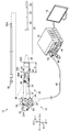
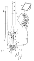
- FIG. 1 is a block diagram of an endoscope system 12 provided with an endoscope 10 according to an embodiment of the present invention.
- the endoscope system 12 includes an endoscope 10, a processor device 14, a light source device 16 and a display 18.
- the treatment tool 56 used in the endoscope system 12 is also shown in FIG.
- the endoscope 10 includes an operation unit 22 provided with a rising operation lever 20 which is an operation member, and an insertion unit 24 provided on the distal end side of the operation unit 22.
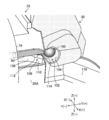
- FIG. 2 is a perspective view of the tip end member 28 in which the stand 30 is in the collapsed position
- FIG. 3 is a perspective view of the tip end member 28 in which the stand 30 is in the upright position.
- the upper direction refers to the Z (+) direction in FIGS. 1 and 2
- the lower direction refers to the Z ( ⁇ ) direction in FIGS. 1 and 2.
- the right direction refers to the X (+) direction of FIG. 2
- the left direction refers to the X (-) direction of FIG.
- the Y (+) direction in FIGS. 1 and 2 points to the distal side of the tip member 28, and the Y ( ⁇ ) direction in FIGS. 1 and 2 points to the proximal side of the tip member 28.
- the operation unit 22 is extended toward the distal end side from the operation unit main body 32 provided with the erecting operation lever 20, the grip unit 34 connected to the operation unit main body 32, and the grip unit 34
- An extension portion 36 is provided, and a proximal end portion of the insertion portion 24 is provided on the distal end side of the extension portion 36 via a bending tube 38.
- the extension portion 36 is provided in the operation portion 22 to provide a movable member 96 (see FIG. 6) described later, and extends from the tip portion of the grip portion 34 gripped by the operator toward the tip end side It is a part of the provided non-gripping area. With respect to the extension portion 36, an area A from the annular interference prevention wall 40 of the interference prevention portion 300, which is provided in the grip portion 34, to the base end 38A of the bending tube 38 is defined as the extension portion 36. Do.
- a universal cord 46 is provided on the operation unit main body 32 of the operation unit 22.
- a light source connector 50 is provided on the distal end side of the universal cord 46, and an electrical connector 48 is branched and provided on the light source connector 50.
- the electrical connector 48 is a processor unit 14 and the light source connector 50 is a light source unit 16 Connected to
- the insertion portion 24 is configured by connecting the distal end portion 26, the bending portion 52, and the flexible portion 54 from the distal end side toward the proximal end side.
- the following contents are provided inside the insertion portion 24. That is, the operation for changing the lead-out direction of the treatment instrument channel 58 for guiding the distal end portion 56A of the treatment instrument 56 of FIG. 1 to the distal end member 28 of FIG. 2 and the distal end portion 56A of the treatment instrument 56 led out from the distal end member 28 1 and an erecting operation wire channel 62 (hereinafter referred to as a wire channel 62) for guiding the distal end portion of the wire 60 to the distal end member 28.
- a light guide (not shown) for guiding illumination light supplied from the device 16 to the tip member 28 of FIG. 2, an air / water feeding tube (not shown), an angle wire (not shown), and a signal cable (not shown) Etc. contents are provided.
- the operation unit 22 is generally formed in a substantially cylindrical shape, and has a cylindrical axis B along the Y (+)-Y (-) direction.
- a pair of angle knobs 64, 64 for bending the bending portion 52 are disposed on the side surface 22A on one side of the vertical cross section including the cylindrical axis B of the operation portion 22 as a boundary.
- the pair of angle knobs 64, 64 are coaxially rotatably provided.
- the bending portion 52 has a structure in which a plurality of angle rings (not shown) are rotatably connected to each other.
- the curved portion 52 is configured by covering the outer periphery of this structure with a tubular mesh woven with metal wires, and covering the outer circumferential surface of the mesh with a cylindrical outer shell made of rubber.
- four angle wires (not shown) are disposed from the curved portion 52 configured as described above to the angle knobs 64, 64, and these angle wires are set by turning the angle knobs 64, 64.
- the bending portion 52 is bent vertically and horizontally.
- an air supply / water supply button 66 and a suction button 68 are juxtaposed on the operation unit main body 32 of the operation unit 22.
- air supply / water supply button 66 By operating the air supply / water supply button 66, air and water can be ejected from the air supply / water supply nozzle 70 provided in the tip end member 28 of FIG.
- suction button 68 of FIG. 1 By operating the suction button 68 of FIG. 1, it is possible to suction body fluid such as blood from the suction port which also serves as the treatment instrument outlet 72 provided in the tip end member 28 of FIG.
- the grip portion 34 of the operation portion 22 of FIG. 1 is provided with a treatment tool introduction port 42 for introducing the treatment tool 56.
- the treatment instrument 56 introduced from the treatment instrument inlet 42 with the tip 56A at the top is inserted into the treatment instrument channel 58 of FIG. It is derived from the outlet 72 to the outside.
- a rising operation lever 20 is rotatably provided coaxially with the angle knobs 64, 64.
- the erecting control lever 20 is rotationally operated by the operator's hand holding the grip 34.
- the rising operation lever 20 is rotated, the wire 60 in FIG. 2 is pushed and pulled by the rising operation mechanism 120 (see FIGS. 9 and 10) that operates in conjunction with the rotation operation of the rising operation lever 20.
- the posture of the stand 30 connected to the tip end side of 60 is changed between the standing position of FIG. 3 and the reclining position of FIG.
- the above-mentioned rising operation mechanism 120 will be described later.
- the flexible portion 54 shown in FIG. 1 has a helical tube (not shown) formed by spirally winding a thin metal strip having elasticity.
- the flexible portion 54 is configured by covering the outer side of the spiral tube with a cylindrical mesh woven with metal wires and covering the outer circumferential surface of the mesh with a cylindrical outer shell made of resin.
- the endoscope 10 of the embodiment configured as described above is a side-view endoscope used as a duodenoscope, and the insertion portion 24 is inserted into a subject through an oral cavity.
- the insertion portion 24 is inserted from the esophagus through the stomach to the duodenum, and a treatment such as a predetermined examination or treatment is performed.
- a biopsy forceps having a cup capable of collecting a living tissue at the tip end 56A is illustrated, but the invention is not limited thereto.
- a treatment tool such as a contrast tube or a knife for EST (Endoscopic Sphincterotomy) is used.
- the distal end portion 26 of the insertion portion 24 is composed of a distal end member 28 and a cap 76 detachably mounted on the distal end member 28.
- the cap 76 is formed in a substantially cylindrical shape whose front end side is sealed, and a substantially rectangular opening window 76A is formed in a part of the outer peripheral surface thereof.
- the opening window 76 A of the cap 76 is in communication with the treatment instrument outlet 72 of the distal end member 28.
- the distal end portion 56A of the treatment instrument 56 derived from the treatment instrument outlet 72 is derived from the opening window 76A to the outside.
- the cap 76 is made of an elastic material, for example, a rubber material such as fluororubber or silicone rubber, or a resin material such as polysulfone.
- An engagement portion (not shown) engaged with a groove (not shown) formed on the distal end member 28 is provided on the proximal end side of the cap 76, and this engagement portion is engaged with the groove of the distal end member 28
- the cap 76 is attached to the tip member 28.
- the cap 76 is removed from the tip member 28 and cleaned or disinfected or discarded as disposable.
- the tip member 28 is made of a metal material having corrosion resistance. Further, the distal end member 28 is integrally provided with a partition wall 78 projecting toward the tip end and a partition wall 80 opposed to the partition wall 78. Between the partition wall 78 and the partition wall 80, a stand storage chamber 82 for storing the stand 30 is formed. A treatment instrument outlet 72 for guiding the treatment instrument 56 to the outside is formed on the proximal end side of the stand storage chamber 82, and the distal end of the treatment instrument channel 58 is connected to the treatment instrument outlet 72.
- the treatment instrument channel 58 is inserted into the inside of the insertion portion 24 of FIG.
- the proximal end of the treatment instrument channel 58 is connected to a distal end tube 202 of a branch tube 200 (see FIG. 10) provided inside the operation unit 22.
- the branch pipe 200 has a known structure, and the proximal end thereof is branched into two pipes 204 and 206, and the treatment instrument inlet 42 is formed at the proximal end of one of the pipes 204. Therefore, the distal end portion 56A of the treatment tool 56 introduced into the treatment tool channel 58 from the treatment tool introduction port 42 via the conduit 204 is inserted into the treatment tool channel 58 and is erected from the treatment tool outlet 72 of FIG. It is led out to the table storage room 82. Then, the leading end 56A of the treatment tool 56 led to the stand storage chamber 82 changes the lead-out direction according to the posture between the upright position and the fall position of the stand 30 disposed in the stand storage chamber 82. Be done. Further, the distal end of a suction pipe 208 for suctioning a body fluid such as blood is connected to the proximal end of the other pipe line 206 of the branch pipe 200 shown in FIG.
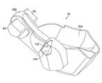
- FIG. 4 is an enlarged perspective view of the stand 30. As shown in FIG. 4, a guide surface 30A is provided on the upper surface of the stand 30. Along the guide surface 30A, the tip 56A of the treatment instrument 56 of FIG. 1 is led out of the opening window 76A of the cap 76 of FIG.
- the stand 30 is provided with pivots 84 and 86 on both sides of its base 30B.
- the axial direction of the pivot shafts 84 and 86 is set in the X (+)-X (-) direction of FIG. 2 when the stand 30 is attached to the tip end member 28.
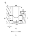
- FIG. 5 is a sectional view of an essential part showing a mounting structure of the stand 30 to the tip end member 28.
- the axes of the pivot shafts 84 and 86 are coaxially disposed via the base portion 30B of the stand 30, and the pivot shaft 84 is rotatably fitted to the concave bearing portion 78A of the partition wall 78.
- the pivot shaft 86 is rotatably fitted in the concave bearing portion 80A of the partition 80.
- the pivot shafts 84 and 86 are mounted to the bearings 78A and 80A in the axial direction of the pivot shafts 84 and 86 with a predetermined amount of play x.
- an optical system storage chamber 88 is provided inside the partition wall 78.
- An illumination window 90 and an observation window 92 are disposed adjacent to each other at the top of the optical system storage chamber 88, and an air / water feed nozzle 70 directed to the observation window 92 is provided on the tip member 28.
- the air / water feed nozzle 70 is connected to an air / water feed device (not shown) via an air / water feed tube (not shown) inserted into the insertion portion 24, and the air / water feed button 66 of the operation unit 22 shown in FIG.
- the air or water is jetted from the air / water feed nozzle 70 toward the observation window 92 by operating the. Thereby, the observation window 92 is cleaned.
- the illumination unit includes an illumination lens (not shown) disposed inside the illumination window 90, and a light guide (not shown) disposed so that the tip surface faces the illumination lens.
- the light guide is disposed from the insertion portion 24 of the endoscope 10 to the universal cord 46 via the operation portion 22, and the proximal end thereof is connected to the light source device 16 via the light source connector 50. Thereby, the irradiation light from the light source device 16 is transmitted through the light guide and is irradiated from the illumination window 90 to the outside.
- the above-described imaging unit includes an imaging optical system (not shown) disposed inside the observation window 92 and an imaging device (not shown) of a complementary metal oxide semiconductor (CMOS) type or a charge coupled device (CCD) type. ing.
- the imaging device is connected to the processor device 14 via a signal cable (not shown) inserted into the insertion portion 24 of FIG.
- the imaging signal of the subject image obtained by the imaging unit is output to the processor unit 14 through the signal cable and subjected to image processing, and then displayed on the display 18 as the subject image.
- the tip side of the wire 60 is disposed outside the outlet 74 and connected to the stand 30 as shown in FIGS. 2 and 3. Further, as shown in FIG. 6, the proximal end side of the wire 60 is disposed outside the introduction port 94 provided in the operation unit 22, and is connected to the movable member 96 (see FIG. 10).
- the outlet 74 is an example of the distal end opening of the present invention
- the inlet 94 is an example of the proximal end opening of the present invention.
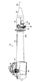
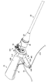
- FIG. 6 is a perspective view of the operation unit 22 and is a perspective view illustrating the other side 22B opposite to the one side 22A of the operation unit 22 shown in FIG.
- the introduction port 94 is provided in the extension portion 36 of the operation unit 22.
- An attachment member 98 is provided at the proximal end of the wire 60 disposed outside from the introduction port 94, and the attachment member 98 is detachably engaged with an engagement hole (described later) of the movable member 96. There is.
- removable engagement refers to the movable member 96 without using other fasteners (for example, a screw, a bolt, a nut, etc.) as described in “One-touch detachable engagement with one touch” described later.
- fasteners for example, a screw, a bolt, a nut, etc.
- the movable member 96 and the mounting member 98 can be attached and detached only by the relative movement of the mounting member 98 with respect to the mounting member 98, but other fasteners are used to attach and detach the mounting member 98 and the movable member 96. It is the meaning also including what to do.
- the operation unit 22 is provided with a movable member 96.
- the movable member 96 is disposed exposed to the outside of the operation unit 22 and operates in conjunction with the operation of the rising operation lever 20 by the rising operation mechanism 120 described later.
- the movable member 96 is rotatably disposed on the other side 22B opposite to the side 22A on which the angle knobs 64 are provided.
- the arrangement position is not limited, and it may be rotatably arranged at a predetermined position of the operation unit 22.
- the movable member 96 is a driven lever that rotates in conjunction with the rotation operation of the rising operation lever 20.
- the standing operation mechanism 120 is disposed inside the operation unit 22 and operates the movable member 96 in conjunction with the operation of the standing operation lever 20. Therefore, when the rising operation lever 20 is operated to rotate, the movable member 96 operates via the rising operation mechanism 120, and the wire 60 (see FIG. 2) connected to the movable member 96 is pushed and pulled.
- the rising operation mechanism 120 will be described later.
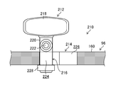
- the wire 60 is provided with an engagement member 100 at its tip. Further, the stand 30 is provided with the accommodation groove 102 engaged with the engagement member 100 so as to be detachably engaged, and the accommodation groove 102 having the opening 104 formed on the X (+) direction side. Thus, the distal end of the wire 60 is connected to the stand 30 by accommodating the engagement member 100 provided at the distal end of the wire 60 in the accommodation groove 102 through the opening 104.
- the engagement member 100 is a sphere
- the accommodation groove 102 is a spherical recess for accommodating the engagement member 100 of a sphere.
- the shapes of the engagement member 100 and the accommodation groove 102 are not limited to the above-described shapes, but the engagement member 100 may be a sphere and the accommodation groove 102 may be a spherical recess to push and pull the wire 60.
- the sliding resistance between the engagement member 100 and the accommodation groove 102 caused by the operation can be reduced. Therefore, the push and pull operation of the wire 60 can be performed smoothly.
- the leading end member 28 is provided with an engagement guiding portion 106 which is continuously provided in the accommodation groove 102 in the upright position of FIG. 3.
- the engagement guiding portion 106 has a function of guiding the engagement member 100 led out from the outlet 74 to the opening 104 of the housing groove 102.
- the outlet 74 is provided in the tip member 28 and is in communication with the inlet 94 (see FIG. 6) via a wire channel 62 provided in the inside of the insertion portion 24.
- the engagement member 100 is inserted into the wire channel 62 (FIG. 2). (See reference) and is led out from the outlet 74 to the outside. Then, the engaging member 100 is guided toward the opening 104 of the accommodation groove 102 of the stand 30 by the engagement guiding portion 106 by the continuous introduction operation of the wire 60, and is engaged with the accommodation groove 102 from the opening 104 Be done.
- the engagement member 100 of the wire 60 can be engaged with the accommodation groove 102 of the stand 30 only by the introduction operation of the wire 60.
- FIG. 7 is an enlarged perspective view in which the engagement member 100 is engaged with the accommodation groove 102 via the engagement guiding portion 106.
- FIG. FIG. 8 is an explanatory view sequentially showing an operation until the engagement member 100 is guided by the engagement guiding portion 106 and engaged with the accommodation groove 102. As shown in FIG.
- the engagement guiding portion 106 guides the engagement member 100 led out from the outlet 74 to the opening 104 of the accommodation groove 102, and the inside of the engagement guide path 108.
- a deformation generation unit 110 connected to the opening 104 of the accommodation groove 102.
- the deformation generating portion 110 contacts the engaging member 100 advancing in the engagement guide path 108 toward the opening 104 in the Y (+) direction, and guides the engaging member 100 in the Y (+) direction while X (( Guide in the +) direction.
- the distal end side of the wire 60 is elastically deformed in the direction (X (+) direction) gradually away from the opening 104 as the engagement member 100 approaches the opening 104 along the guiding guide path 108.
- the engagement member 100 advancing in the engagement guide path 108 is moved in the X (-) direction by the restoring force of the wire 60 and engaged with the accommodation groove 102 from the opening 104.
- the engagement guide path 108 is formed by notching a part of the circumferential surface 28A of the tip member 28 in a concave shape, and is gradually inclined in the X (+) direction from the outlet 74 toward the Y (+) direction It is a face.
- a deformation generating portion 110 is formed on the tip end side of the engagement guide path 108.
- the engagement guiding portion 106 is formed with a groove 112 for retracting the leading end side of the wire 60 when the engagement member 100 is engaged with the accommodation groove 102.
- a groove 114 is formed which allows the distal end side of the wire 60 to be retracted and released when the engagement member 100 is engaged with the accommodation groove 102.
- the width dimension of the groove 112 in the direction orthogonal to the paper surface of FIG. 8 is larger than the diameter of the wire 60, and the engaging member 100 passing through the deformation generating portion 110 does not get into the groove 112. Less than diameter.
- the width dimension of the groove 114 in the direction orthogonal to the paper surface of FIG. 8 is larger than the diameter of the wire 60, and the engaging member 100 engaged with the accommodation groove 102 does not come off in the Y (-) direction. , Smaller than the diameter of the engagement member 100.
- the guiding part 106 for engagement is a form suitable for engaging the engaging member 100 with the accommodation groove 102 in a state where the stand 30 is in the upright position. That is, as shown in FIG. 7, the housing groove 102 is disposed at a position facing the outlet 74 with the stand 30 positioned at the standing position. Therefore, by moving the engaging member 100 straight from the outlet 74, the engaging member 100 can be engaged with the housing groove 102 of the stand 30 located at the standing position via the guiding portion 106 for engagement.
- the leading end member 28 is provided with a guiding surface 116 for detachment, and the guiding surface 116 for detachment is provided on the upper surface of the partition wall 80 (see FIG. 2).
- the separating guide surface 116 is a guide surface (see FIGS. 2 and 3) inclined in the Z ( ⁇ ) direction toward the X (+) direction. Further, from the inside of the housing groove 102 when the wire 60 is further pushed in the state where the engaging member 100 is engaged with the housing groove 102 and the stand 30 is located at the reclining position, the guiding surface 116 for detachment is It functions as a surface for guiding the wire 60 in the direction in which the engaging member 100 separates out of the opening 104.
- the attachment member (described later) provided at the proximal end of the wire 60 is removed from the engagement hole (described later) of the movable member 96, and then the introduction port of the extending portion 36
- the wire 60 is pushed in from 94 to position the stand 30 from the upright position of FIG. 3 to the collapsed position of FIG.
- the wire 60 is guided by the detachment guiding surface 116 of the tip member 28 in the X (+) direction in which the engaging member 100 is detached from the inside of the accommodation groove 102 to the outside of the opening 104.
- Ru As a result, the restoring force of the wire 60 easily disengages the engagement member 100 from the inside of the accommodation groove 102 to the outside of the opening 104.
- FIG. 9 is a configuration diagram showing an overall configuration of the rising operation mechanism 120.
- FIG. 10 is a side view of the standing operation mechanism 120 of FIG. 9 and 10, the exterior case (not shown) of the operation unit 22 is omitted, and the inside of the operation unit 22 is shown.
- the standing operation mechanism 120 is provided inside the operation unit 22.
- the standing operation mechanism 120 is a power transmission mechanism that connects the standing operation lever 20 and the movable member 96 and transmits the rotation operation of the standing operation lever 20 to the movable member 96.
- the erecting operation mechanism 120 rotates the linear motion of the wire 126, which is linearly moved by the first transforming mechanism 124, the first transforming mechanism 124 that converts the rotational motion of the erecting manipulation lever 20 into linear motion, and the rotational motion of the wire 126 And a second conversion mechanism 128 for rotating the movable member 96.
- the wire 126 is an example of the drive member of the present invention.
- the first conversion mechanism 124 has a crank member 130 whose base end is connected to the rising operation lever 20, a first slider 132 whose base end is connected to the tip of the crank member 130, and a base end at the tip of the first slider 132 And a second slider 134 connected to each other.
- the proximal end of the wire 126 is connected to the distal end of the second slider 134, and the distal end of the wire 126 is connected to the second conversion mechanism 128 including the speed reduction mechanism.
- the crank member 130, the first slider 132, and the second slider 134 move along the cylindrical axis B in conjunction with each other when the rising control lever 20 is rotated. It moves in a straight line. Thereby, the wire 126 linearly moves along the cylindrical axis B, and the linear movement is transmitted to the second conversion mechanism 128.
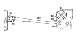
- the second conversion mechanism 128 includes a lever 136, a first gear 138, a second gear 140, a third gear 142, and a fourth gear 144.
- the first gear 138, the second gear 140, the third gear 142, and the fourth gear 144 constitute a speed reduction mechanism.
- the lever 136 is rotatably supported by the bracket 146 via the shaft 148, and the tip of the wire 126 is connected. Thus, the lever 136 is rotated about the axis 148 by the linear motion of the wire 126.
- the first gear 138 is integrally provided with the lever 136 and is rotated about an axis 148.
- the second gear 140 meshes with the first gear 138 and is rotatably supported by the bracket 146 via the shaft 150.
- the third gear 142 is integrally provided with the second gear 140 and coaxial with the second gear 140.
- the fourth gear 144 is provided coaxially with the drive shaft 152 of the movable member 96, and is rotatably supported by the bracket 146 via the drive shaft 152 together with the movable member 96.
- the third gear 142 is engaged with the fourth gear 144.
- the second conversion mechanism 128 configured as described above, when the linear movement of the wire 126 is transmitted to the lever 136, the first gear 138 is rotationally operated together with the lever 136, and the rotational movement of the first gear 138 Is transmitted to the fourth gear 144 via the second gear 140 and the third gear 142, and the fourth gear 144 is rotated. As a result, the movable member 96 integral with the fourth gear 144 is rotated about the drive shaft 152.
- the rotation operation of the rising operation lever 20 is transmitted to the movable member 96 via the first conversion mechanism 124, the wire 126, and the second conversion mechanism 128. Can. The movable member 96 is thereby rotated about the drive shaft 152.
- the rotational operation of the rising operation lever 20 is decelerated and transmitted to the movable member 96 by the second conversion mechanism 128 including the speed reduction mechanism. That is, the rotation angles of the leg portions 162 and 164 of the movable member 96 become smaller with respect to the rotation angle of the lever 136 operated by the operation of the rising operation lever 20. As a result, the force required to operate the rising operation lever 20 can be further reduced, and the control of the rising and lowering posture of the rising stand 30 by the rising operation lever 20 becomes easy.
- the wire 126 is illustrated as an example of the driving member of the standing operation mechanism 120.
- the use of the wire 126 as a drive member has the following advantages. That is, when converting the linear motion of the second slider 134 into the rotational motion of the lever 136, the wire 126 can perform curvilinear motion (slack), so that the link mechanism can be omitted and space constraints are reduced.
- the second slider 134 and the lever 136 are connected by the link mechanism, there is less space for the force in the rising operation mechanism 120, but by using the wire 126, the force is released by the wire 126 being slackened. Therefore, the load on the rising operation mechanism 120 can be reduced. Therefore, even if any force is applied to the movable member 96 exposed to the outside of the operation unit 22 from the outside, the force can be released by loosening the wire 126, so the load applied to the standing operation mechanism 120 is reduced. can do.
- the movable member 96 includes a flat beam 160 and legs 162 and 164 provided at both ends of the beam 160, as shown in FIGS. It is done. Then, as shown in FIGS. 9 and 10, the drive shaft 152 provided on the leg portion 162 side is rotatably supported by the exterior case (not shown) of the operation portion 22 via the O ring 166, and the leg portion 164 side. A driven shaft 168 provided on the housing is rotatably supported by an outer case (not shown) via an O-ring (not shown). The O-rings 166 keep the operation unit 22 watertight.
- the rotation axes of the drive shaft 152 and the driven shaft 168 of the movable member 96 are set in a direction (X (+)-X (-) direction) perpendicular to the axial direction of the wire 60. That is, since the movable member 96 is rotatably provided with the direction perpendicular to the axial direction of the wire 60 as the rotation axis, the wire 60 can be pushed and pulled smoothly.
- connection structure 170 according to the first embodiment for connecting the proximal end of the wire 60 and the movable member 96 will be described with reference to FIGS. 11 to 15.
- FIG. 11 is a perspective view of the connection structure 170 viewed from the other side 22B of the operation unit 22.
- FIG. 12 is a perspective view of the connection structure 170 shown in FIG. 11 as viewed from the left side.
- FIG. 13 is a perspective view of the wire 60 and the wire assembly 172 provided with the attachment member 98 provided at the proximal end of the wire 60
- FIG. 14 is a front view of the attachment member 98
- FIG. 10 is a perspective view of the extending portion 36 showing the inlet 94 and the movable member 96.
- FIGS. 11 to 15 are explanatory diagrams for describing the connecting structure 170, and in FIGS. 11 and 12 among them, the proximal end of the wire 60 and the movable member 96 are connected by the connecting structure 170.
- the drawing is shown, and the mounting member 98 and the movable member 96 that constitute the connecting structure 170 are shown in FIGS. 13 to 15.
- the movable member 96 is provided with an engagement hole 174 in which the attachment member 98 is detachably engaged with one touch.
- the engagement hole 174 is formed along the longitudinal direction of the beam portion 160 of the movable member 96, and is constituted by a through hole penetrating the front and back surfaces of the beam portion 160.
- the pair of engaging portions 176, 176 (see FIG. 14) of the mounting member 98 is detachably engaged with the engaging hole 174 by one touch.
- the proximal end of the wire 60 and the movable member 96 are coupled to the outside of the operation unit 22.
- the engagement holes 174 may be through holes penetrating the front and back surfaces of the beam portion 160, or may be concave non-through holes not penetrating.
- “removably engageable with one touch” is used to attach the attachment member 98 to the movable member 96 without using other fasteners (eg, screws, bolts, or nuts). This means that the operation and the operation for removing the mounting member 98 from the movable member 96 can be performed only by the relative movement of the mounting member 98 with respect to the movable member 96, respectively. The same applies to other embodiments described later.
- the mounting member 98 shown in FIG. 14 is a substantially triangular plate-like body, and a hole 180 to which the base end of the wire 60 is connected is formed at the core 178 at the center.
- the engaging portions 176, 176 of the mounting member 98 are provided on both sides of the core portion 178 via slit-like notches 182, and have a pair of elastically deformable portions 184 which are elastically deformed and engaged with the engaging holes 174. It is provided.
- the elastically deformable portion 184 is formed with a pair of claw portions 186 that lock to the edge portions 175, 175 (see FIGS. 15 and 16) on both sides in the longitudinal direction of the engagement hole 174.
- the pair of claw portions 186 are displaced in a direction in which they approach each other by elastic deformation of the pair of elastically deformable portions 184 when engaging or disengaging the engagement holes 174 and the engagement portions 176.
- connection procedure of the proximal end of the wire 60 and the movable member 96 by the connection structure 170 of the first embodiment will be described with reference to FIGS. 16 to 18.
- the distal end of the wire 60 is connected to the stand 30.
- FIG. 16 shows that the wire 60 is inserted from the introduction port 94 with the engagement member 100 (see FIG. 13) at the top, and the insertion operation of the wire 60 raises the tip of the wire 60. Connect to the platform 30.
- FIG. 17 shows the state of the mounting member 98 in a state in which the tip of the wire 60 is connected to the stand 30.
- the lower tapered portion 187 of the claw portion 186 is abutted and pushed into the edge on both sides of the engagement hole 174.
- the space between the claws 186, 186 is narrowed, and the claws 186, 186 are engaged with the edges 175, 175 on both sides of the engagement hole 174, as shown in the connection diagram of FIG.
- the mounting member 98 is connected to the
- the operation for attaching the attachment member 98 to the movable member 96 can be performed only by the relative operation of the attachment member 98 with respect to the movable member 96. That is, according to the connection structure 170 of the first embodiment, the attachment member 98 can be engaged with the movable member 96 with one touch.
- the pair of engaging portions 176, 176 of the mounting member 98 are grasped with fingers, and the distance between the claw portions 186, 186 is determined from the dimension in the longitudinal direction of the engaging hole 174. It can be narrowed to become smaller. That is, the pair of elastically deforming portions 184 are displaced in a direction in which they approach each other by elastic deformation. Then, after the claws 186, 186 are inserted into the engagement holes 174, the finger portions are loosened to spread the space between the claws 186, 186, thereby the edges of the engagement holes 174 on both sides of the claws 186, 186. Lock to 175 and 175. Thereby, the attachment member 98 engages with the movable member 96 at one touch.
- the movable member 96 operates in the direction of the arrow C or D as shown in the operation explanatory view of the movable member 96 shown in FIG. Then, in conjunction with the operation of the movable member 96, the wire 60 is pushed and pulled by the movable member 96 via the mounting member 98. As a result, the stand 30 is pivoted between the upright position and the collapsed position.
- the engagement hole 174 is formed in the movable member 96 and the engagement portion 176 is formed in the attachment member 98.
- the engagement portion 176 is formed in the movable member 96, and the engagement hole is formed in the attachment member 98 174 may be formed. That is, as long as the engaging hole 174 is provided in one of the movable member 96 and the mounting member 98, and the engaging portion 176 is provided on the other in the engaging hole 174 so as to be detachably engaged at one touch. Good.
- the claw portion 186 may be provided not on the longitudinal direction side of the beam portion 160 of the movable member 96 but on the lateral direction side.
- the engagement holes 174 may be two engagement holes formed independently along the longitudinal direction of the beam portion 160.
- the endoscope 10 is used for various examinations or treatments. Thereafter, when the endoscope 10 is cleaned, the following operation is performed.
- the cap 76 shown in FIG. 2 is removed from the tip member 28.
- the engagement portions 176 and 176 of the mounting member 98 are removed from the engagement holes 174 (see FIG. 15) of the movable member 96, and the wire 60 is removed from the movable member 96.
- the wire 60 is pushed in through the introduction port 94 of the extending portion 36 to position the stand 30 from the standing position of FIG. 3 to the lying position of FIG. Thereafter, when the wire 60 is further pushed in, the engagement member 100 is disengaged from the inside of the accommodation groove 102 to the outside of the opening 104.
- the tip of the wire 60 is removed from the stand 30 by this operation.
- the wire 60 is pulled out of the introduction port 94 and the wire channel 62 is emptied. Thereafter, cleaning of the tip member 28, the stand 30, and the wire channel 62 of the wire 60 is performed.
- the connecting structure 170 of the first embodiment is such that the mounting member 98 is connected to the movable member 96 outside the operation portion 22. Can be easily removed. Specifically, the pair of engaging portions 176, 176 of the mounting member 98 are pinched with fingers to narrow the space between the claws 186, 186 to be smaller than the longitudinal dimension of the engaging hole 174. Thereafter, the claws 186, 186 are pulled out of the engagement holes 174.
- the operation for separating the mounting member 98 from the movable member 96 can be performed only by the relative movement of the mounting member 98 with respect to the movable member 96. That is, according to the connection structure 170 of the first embodiment, the attachment member 98 is detached from the movable member 96 at one touch.
- connection structure 170 of the first embodiment after the tip of the wire 60 is connected to the stand 30, the connection hole 170 of the movable member 96 is attached outside the operation unit 22.
- the proximal end of the wire 60 and the movable member 96 can be connected only by engaging the engaging portions 176, 176 of the member 98. Further, when the proximal end of the wire 60 is removed from the movable member 96 at the time of cleaning the endoscope 10, only by removing the attachment member 98 from the engagement hole 174 of the movable member 96 outside the operation unit 22, The proximal end of the wire 60 can be removed from the movable member 96.
- connection structure 170 of the first embodiment the distal end of the cable and the endoscope of Patent Document 1 for attaching and detaching the proximal end of the wire to the connector within the operation unit are attached and detached to the collet and the nut
- the attachment / detachment operation of the proximal end of the wire 60 to the movable member 96 can be easily performed.
- the wire 60 is drawn from the introduction port 94 in the above embodiment, the wire 60 may be drawn out from the lead-out port 74 of the tip member 28. In this case, the wire 60 can be pulled out from the outlet 74 by removing the attachment member from the proximal end of the wire 60 prior to the wire 60 being pulled out.
- FIG. 19 is a perspective view showing a modified example of the connection structure 170 of the first embodiment shown in FIG. 11 to FIG.
- connection structure 170A of the modification shown in FIG. 19 the same or similar members as or to the connection structure 170 shown in FIG. 11 to FIG.
- the engagement hole 174A formed in the movable member 96 is a circular through hole. Further, the engaging portion 176A of the mounting member 98A has a cylindrical portion 177 inserted into the engaging hole 174A. Further, the elastically deformable portion of the mounting member 98A is constituted by a slitting portion 184A provided at the tip of the cylindrical portion 177, and a claw portion 186A is formed on the outer peripheral surface of the slitting portion 184A.
- the connecting structure 170A configured as described above, when the slotted portion 184A of the cylindrical portion 177 is inserted into the engagement hole 174A, the slotted portion 184A is reduced in diameter by elastic deformation. Thereby, when the grooving portion 184A passes through the engagement hole 174A and then the grooving portion 184A passes through the engagement hole 174A, the grooving portion 184A returns to its original diameter. As a result, as shown in the cross-sectional view of the connecting structure 170A shown in FIG. 20, the claw portion 186A of the slotted portion 184A engages with the back surface 160A of the beam portion 160 of the movable member 96. Engage with one touch.
- the attaching and detaching operation of the mounting member 98A with respect to the movable member 96 is performed outside the operation unit 22 as in the connecting structure 170.
- the mounting operation only needs to insert the engagement portion 176A into the engagement hole 174A. By this mounting operation, the proximal end of the wire 60 can be easily coupled to the movable member 96 via the mounting member 98A.
- the slitting portion 184A is pinched with a finger to reduce the diameter of the slitting portion 184A. After this, the slotted portion 184A is pulled out of the engagement hole 174A.
- connection structure 170A of the modification similarly to the connection structure 170, an operation for attaching the attachment member 98A to the movable member 96 and an operation for detaching the attachment member 98A from the movable member 96, respectively. It can be performed only by the relative movement of the mounting member 98A with respect to the movable member 96. That is, according to the connecting structure 170A, the mounting member 98A is detachably engaged with the movable member 96 with one touch.
- FIG. 21 is a cross-sectional view showing the valve body 95 mounted on the inlet port 94.
- the proximal end of the wire 60 is disposed outside the introduction port 94, it is preferable to attach the valve body 95 to the introduction port 94. Thereby, it is possible to prevent the fluid in the body cavity flowing backward from the outlet port 74 of the tip member 28 through the wire channel 62 from leaking through the inlet port 94.
- the interference prevention unit 300 is provided to prevent the movable member 96 from being interfered with by the locking device 300 described later, and the operation of the movable member 96 is restricted.
- the insertion portion 24 when performing treatment in a duct such as a bile duct or a pancreatic duct, the insertion portion 24 is inserted to the vicinity of the Vater papilla of the duodenum, and a treatment instrument is inserted from the treatment instrument inlet 42 of the operation unit 22 .
- a guide wire is inserted through the treatment tool channel 58 of the insertion portion 24 to insert the guide wire from the Vater's papilla into the biliary tract or pancreatic duct.
- the treatment instrument is inserted into the biliary tract or pancreatic duct with the guide wire as a guide.
- the guide wire locking device 302 shown in FIG. 22 is used for the purpose of fixing the guide wire because the guide wire can not be guided to the treatment position after replacement when the guide wire is pulled out of the papilla.
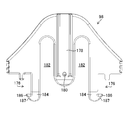
- the guide wire locking device 302 includes a body portion 308 in which the slit 304 and the lay-down 306 are formed to fix the guide wire, and a band for fixing the guide wire locking device 302 to the endoscope 10 by winding around the endoscope 10. And a unit 310.
- the movable member 96 can be exposed and arranged outside the operation unit 22 so that the attachment and detachment operation of the proximal end of the movable member 96 and the wire 60 can be easily performed.
- the movement of the movable member 96 may be limited by the guide wire locking device 302. Therefore, when attaching the guidewire locking device 302, the guidewire locking device 302 needs to be attached at a position that does not interfere with the movement of the movable member 96.
- the interference prevention unit 300 and mounting the guide wire locking device 302 on the proximal end side of the operation unit 22 from the interference prevention unit 300 the movable member 96 can be prevented from receiving interference by the guide wire locking device 302.
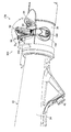
- FIG. 23 is a view in which the guide wire locking device 302 is attached to the endoscope 10 and the guide wire 312 is fixed to the guide wire locking device 302, and FIG. 24 is a view showing the guide wire locking device 302 in the endoscope 10. It is the mounted enlarged view.
- the guide wire locking device 302 fixes the guide wire locking device 302 to the endoscope 10 by winding the band portion 310 between the treatment instrument introduction port 42 provided in the grip portion 34 and the interference prevention portion 300.
- the guide wire 312 is fixed by hooking the guide wire 312 on the slit (not shown in FIG. 23) of the main body portion 308 and the cross bar 306. This prevents the guide wire 312 from moving when the treatment tool 56 is replaced.
- the interference prevention unit 300 includes an interference prevention wall 40 erected from the outer wall surface of the operation unit 22.
- the movable member 96 operates in the arrow C or arrow D direction as described above.
- the interference prevention wall 40 is provided at a position where the movable member 96 or the attachment member 98 does not contact the interference prevention wall 40.
- the interference prevention wall 40 as shown in FIG. 24, it can be made into the flange-like interference prevention board 40A formed over the perimeter around the outer wall surface of the operation part 22.
- FIG. As the interference prevention plate 40A, it is preferable that the band portion 310 of the guide wire locking device 302 has a height that can not be wound around the operation portion 22 of the endoscope 10.
- the height H 1 of the interference prevention wall 40 can be approximately 10 mm.
- the diameter of the interference prevention part 300 including the operation part 22 and the interference prevention wall 40 is 40 mm or more, the band part 310 of the guide wire locking device 302. Can be prevented from winding.
- the interference prevention wall 340 shown in FIG. 25 includes an interference prevention plate 340A annularly formed around the outer wall surface of the operation portion 22, and the interference prevention plate 340A is the operation portion It is formed in a tapered shape in a direction in which it extends from the proximal end side to the distal end side of the reference numeral 22.
- the interference prevention wall 342 may be provided to stand from a part of the outer wall of the operation unit 22.
- FIG. 27 and FIG. 28 show still another modification of the interference prevention wall.
- the interference prevention wall 344 shown in FIG. 27 has an interference prevention plate 344A around the outer wall surface of the operation portion 22, and the outer wall surface of the operation portion 22 of the interference prevention plate 344A on the surface side provided with the movable member 96. I am raising the height. Also, a notch 346 is provided in part of the interference prevention plate 344A.
- the interference prevention wall 348 shown in FIG. 28 has an interference prevention plate 348 A around the outer wall surface of the operation unit 22, in which the height from the outer wall surface of the operation unit 22 provided with the movable member 96 is increased. An opening 350 may be provided in the interference prevention plate 348A.
- FIG. 29 is a view showing still another modified example of the interference prevention wall.
- the interference prevention wall 352 shown in FIG. 29 is formed by arranging a plurality of interference prevention bodies 352B at intervals from each other around the outer wall surface of the operation unit 22.
- the number of interference prevention bodies 352B and the distance between the interference prevention bodies 352B are not particularly limited as long as the band portion 310 of the guide wire locking device 302 can not be attached.
- FIG. 30 and 31 show another embodiment of the interference prevention unit 301.
- FIG. FIG. 30 is a configuration diagram of an endoscope system including an endoscope having an interference prevention unit 301
- FIG. 31 is a perspective view of the interference prevention unit 301.
- the outer diameter of the extension portion 354 is larger than the outer diameter of the grip portion 34, and the step portion 356 is provided between the extension portion 354 and the grip portion 34.
- the outer diameter of the gripping portion 34 is the outermost end of the gripping portion 34 and is the outer diameter at the position of the boundary between the extending portion 354 and the gripping portion 34.
- the outer diameter of the extension 354 is sized such that the band 310 of the guidewire locking device 302 can not be attached. Further, the distance from the position at which the movable member 96 is provided to the grip portion 34 is longer than the movement range of the movable member 96. Thereby, the guide wire locking device 302 can be prevented from being attached to the operating range of the movable member 96.
- the distance from the position at which the movable member 96 is provided to the gripping portion 34 refers to the shortest distance from the rotation axis of the movable member 96 to the boundary between the gripping portion 34 and the extending portion 354.
- connection structure 210 of the second embodiment will be described.
- FIG. 32 is a perspective view of the connection structure 210
- FIG. 33 is an assembled perspective view of the connection structure 210
- FIG. 34 is a cross-sectional view of the main parts of the connection structure 210.
- the same or similar members as or to those of the connecting structure 170 shown in FIGS. 11 to 18 will be described with the same reference numerals.
- connection structure 210 is composed of a movable member 96 and an attachment member 212.
- the beam portion 160 of the movable member 96 is provided with an engagement hole 214
- the attachment member 212 is provided with an engagement portion 216 which is detachably engaged with the engagement hole 214 with one touch.
- the attachment member 212 is composed of a knob portion 218 and a shaft portion 220 constituting the engagement portion 216.
- the base end of the wire 60 is connected to the hole portion 222 formed in the shaft portion 220.
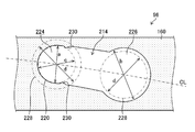
- FIG. 35 is a plan view of the engagement hole 214, and shows the shape of the engagement portion 216 superimposed on the shape of the engagement hole 214. As shown in FIG.
- the engagement hole 214 has a narrow portion 224 having a diameter a and a wide portion 226 having a diameter b larger than the diameter a.
- the first width of the present invention is described by the diameter a
- the second width of the present invention is represented by the diameter b.
- a line CL connecting the center of the narrow portion 224 and the center of the wide portion 226 is a curve.
- the line CL forms a substantially circular arc centered on the inlet 94 (not shown).
- the arrangement of the narrow portion 224 and the wide portion 226 facilitates the operation when the mounting member 212 is engaged with the engagement hole 214. This will be described later.
- the engaging portion 216 of the mounting member 212 shown in FIG. 33 has a shaft portion 220 having an outer diameter c equal to or smaller than the diameter a of FIG. 35 and an enlarged diameter portion 228 provided at the tip of the shaft portion 220. .
- the enlarged diameter portion 228 has an outer diameter d larger than the diameter a and smaller than the diameter b.
- the enlarged diameter portion 228 functions as a retaining member that restricts the shaft 220 from being separated in the axial direction of the shaft 220 from the narrow portion 224. In order to stably hold the shaft portion 220, it is preferable that the difference between the diameter a and the outer diameter c be small.
- the engagement operation will be described.
- the engagement portion 216 of the mounting member 212 can be easily inserted into the engagement hole 214 because the wide portion 226 of the engagement hole 214 is larger than the diameter-increased portion 228.
- the mounting member 212 is then slid from the wide portion 226 to the narrow portion 224.
- the mounting member 212 is fixed to the wire 60, so the mounting member 212 moves on a locus of a substantially arc centering on the introduction port 94.
- the narrow portion 224 and the wide portion 226 are arranged in a substantially arc shape, the mounting member 212 can slide smoothly between the narrow portion 224 and the wide portion 226. Furthermore, when the mounting member 212 is positioned at the narrow portion 224, tension can be applied to the wire 60.
- the engagement hole 214 has a frictional resistance portion 230 between the narrow portion 224 and the wide portion 226.
- the frictional resistance portion 230 is provided at the opening inlet of the narrow portion 224.
- the frictional resistance portion 230 can restrict the shaft portion 220 inserted in the narrow width portion 224 from inadvertently sliding from the narrow width portion 224 to the wide width portion 226.
- the frictional resistance portion 230 is formed so as to project from the wall surfaces of the engagement hole 214 facing each other.
- connection structure 210 configured in this way performs the attachment / detachment operation of the attachment member 212 with respect to the movable member 96 outside the operation unit 22.
- the engaging portion 216 is inserted into the wide portion 226 of the engaging hole 214, and the engaging portion 216 is slid toward the narrow portion 224 to engage the engaging portion 216 with the narrow portion 224.
- the mounting member 212 is engaged with the movable member 96 at one touch.
- the proximal end of the wire 60 can be easily connected to the movable member 96 via the mounting member 212.
- the shaft portion 220 abuts against the frictional resistance portion 230, but the engaging portion 216 has a width by the force of sliding the engaging portion 216.
- the narrow portion 224 can be engaged without any problem.
- the shaft portion 220 is prevented from being separated from the narrow width portion 224 in the axial direction of the shaft portion 220 by the enlarged diameter portion 228.
- the engagement portion 216 is restricted from sliding from the narrow portion 224 to the wide portion 226.
- the attachment member 212 is removed from the movable member 96 when the endoscope 10 is cleaned, the engagement portion 216 of the attachment member 212 is slid from the narrow portion 224 to the wide portion 226 and engaged from the wide portion 226 Pull out the mating part 216. Thereby, the attachment member 212 is detached from the movable member 96 at one touch.
- connection structure 210 of the second embodiment the attachment / detachment operation of the proximal end of the wire 60 to the movable member 96 can be easily performed, as compared with the endoscopes of Patent Documents 1 and 2 described above.
- FIG. 35 illustrates the engagement hole 214 including the frictional resistance portion 230
- the engagement hole 214 may not have the frictional resistance portion 230.
- FIG. 36 is an assembled perspective view of the connection structure 232.
- FIG. 37 is a plan view of the engagement hole 214 formed in the movable member 96, and shows the shape of the engagement portion 236 of the mounting member 234 superimposed on the shape of the engagement hole 214.
- FIG. In explaining the connecting structure 232, the same or similar members as or to those of the connecting structure 210 shown in FIG. 32 to FIG.
- the engagement hole 214 has a narrow portion 224 having a diameter a and a wide portion 226 having a diameter b larger than the diameter a.
- the narrow portion 224 and the wide portion 226 are in a positional relationship as in FIG.
- the engaging portion 236 of the mounting member 234 shown in FIG. 36 is provided at the shaft portion 220 having an outer diameter c equal to or smaller than the diameter a and at the tip of the shaft portion 220, and has an outer diameter f larger than the diameter b
- a plurality of (for example, four) slotted grooves 237 are formed.
- the diameter enlarged portion 238 is inserted into the wide portion 226, the diameter enlarged portion 238 is elastically deformed by the plurality of split grooves 237 to be reduced in diameter.
- connection structure 232 configured in this way performs the attachment / detachment operation of the attachment member 234 with respect to the movable member 96 outside the operation unit 22.
- the enlarged diameter portion 238 is fitted into the wide portion 226 of the engagement hole 214.
- the enlarged diameter portion 238 is elastically deformed by the plurality of split grooves 237 to be reduced in diameter.
- the enlarged diameter portion 238 passes through the wide width portion 226 and thereafter, the enlarged diameter portion 238 passes through the wide width portion 226, the enlarged diameter portion 238 returns to the original diameter.
- the enlarged diameter portion 238 engages with the back surface 160A of the beam portion 160 of the movable member 96, so that the attachment member 234 is prevented from coming off the movable member 96.
- the engaging portion 236 is slid toward the narrow portion 224 to engage the engaging portion 216 with the narrow portion 224.
- the mounting member 234 is engaged with the movable member 96 at one touch.
- the shaft portion 220 is prevented from being separated from the narrow width portion 224 in the axial direction of the shaft portion 220 by the enlarged diameter portion 238.
- the engagement portion 236 is restricted from sliding from the narrow portion 224 to the wide portion 226.
- the mounting member 234 can be reliably connected to the movable member 96.
- the engagement portion 236 of the attachment member 234 is slid from the narrow portion 224 to the wide portion 226. Of the enlarged diameter portion 238 and pull out the enlarged diameter portion 238 from the wide portion 226. Thus, the mounting member 234 is separated from the movable member 96 at one touch.
- connection structure 232 of the third embodiment the attachment / detachment operation of the proximal end of the wire 60 to the movable member 96 can be easily performed, as compared with the endoscopes of Patent Documents 1 and 2 described above.
- FIG. 37 illustrates the engagement hole 214 including the frictional resistance portion 230
- the engagement hole 214 may not have the frictional resistance portion 230.
- FIG. 38 is a perspective view of the connection structure 240
- FIG. 39 is an assembled perspective view of the connection structure 240.
- the same or similar members as or to those of the connecting structure 170 shown in FIGS. 11 to 18 will be described with the same reference numerals.
- connection structure 240 is composed of a movable member 242 and an attachment member 244.
- the movable member 242 includes a leg portion 162, a leg portion 164, and a cylindrical body 246 connecting the leg portion 162 and the leg portion 164.
- the cylindrical body 246 extends in a direction (X (+)-X (-) direction) perpendicular to the axial direction of the wire 60.
- U-shaped grooves 248 and 250 which constitute a rotation restricting stopper are formed at upper end portions of the leg portion 162 and the leg portion 164.
- the attachment member 244 includes an annular body 252 rotatably engaged with the outer periphery of the cylindrical body 246, and pins 254 and 256 which form a rotation restricting stopper together with the grooves 248 and 250.
- the annular body 252 has a C-shaped cross section perpendicular to the longitudinal direction, and by pressing the slit 253 formed in the longitudinal direction against the cylindrical body 246, the diameter is expanded and engaged with the cylindrical body 246 with one touch. Match.
- connection structure 240 configured in this way performs the attachment / detachment operation of the attachment member 244 with respect to the movable member 242 outside the operation unit 22.
- the slit 253 of the annular body 252 of the mounting member 244 is pressed against the cylindrical body 246 of the movable member 242.
- the mounting member 244 engages with the movable member 242 with one touch.
- the proximal end of the wire 60 can be reliably coupled to the movable member 242 via the attachment member 244.
- the annular body 252 engages with the cylindrical body 246, at the same time the pin 254 is engaged with the groove 248 and the pin 256 is engaged with the groove 250, pushing and pulling operation of the wire 60 by the movable member 242 Sometimes, the annular body 252 can be prevented from rotating relative to the cylindrical body 246. Thereby, the wire 60 can be pushed and pulled smoothly.
- the annular member 252 can be made into a cylindrical body 246 by pulling the mounting member 244 in the direction of removing the pins 254, 256 from the grooves 248, 250. , And the annular body 252 is removed from the cylindrical body 246. Thereby, the attachment member 244 is detached from the movable member 242 at one touch.
- connection structure 240 of the fourth embodiment the attachment / detachment operation of the proximal end of the wire 60 to the movable member 242 can be easily performed as compared with the endoscopes of Patent Documents 1 and 2 described above.
- the movable member 242 is provided with the cylindrical body 246, and the attachment member 244 is provided with the annular body 252.
- the cylindrical member 246 is provided in any one of the movable member 242 and the attachment member 244
- An annular body 252 may be provided on the
- the wire 126 is illustrated as an example of the driving member of the standing operation mechanism 120, but instead of the wire 126, a link mechanism may be adopted.
- FIG. 40 shows a main part structure in which the first slider 132 and the lever 136 are connected by a link sheet metal 260 which is a link mechanism.
- FIG. 41 is an operation explanatory view of the link mechanism of FIG. 40.
- the tip of the link sheet metal 260 is rotatably connected to the base end of the first slider 132 via the pin 262, and the base end of the link sheet metal 260 is connected to the lever 136 via the pin 264. It is connected rotatably.
- a duodenoscope was illustrated as an example of the endoscope 10, but in the case of an endoscope provided with a stand for adjusting the lead-out direction of the treatment tool at the distal end of the insertion portion, ultrasound endoscopy
- the present invention can be applied to various endoscopes such as mirrors.
Landscapes
- Health & Medical Sciences (AREA)
- Life Sciences & Earth Sciences (AREA)
- Surgery (AREA)
- Engineering & Computer Science (AREA)
- Physics & Mathematics (AREA)
- Optics & Photonics (AREA)
- Biophysics (AREA)
- Animal Behavior & Ethology (AREA)
- Pathology (AREA)
- Radiology & Medical Imaging (AREA)
- Veterinary Medicine (AREA)
- Biomedical Technology (AREA)
- Heart & Thoracic Surgery (AREA)
- Medical Informatics (AREA)
- Molecular Biology (AREA)
- Nuclear Medicine, Radiotherapy & Molecular Imaging (AREA)
- General Health & Medical Sciences (AREA)
- Public Health (AREA)
- Mechanical Engineering (AREA)
- Astronomy & Astrophysics (AREA)
- General Physics & Mathematics (AREA)
- Endoscopes (AREA)
- Instruments For Viewing The Inside Of Hollow Bodies (AREA)
Abstract
Description
12 内視鏡システム
14 プロセッサ装置
16 光源装置
18 ディスプレイ
20 起立操作レバー
22 操作部
22A 一方の側面
22B 他方の側面
24 挿入部
26 先端部
28 先端部材
28A 周面
30 起立台
30A ガイド面
30B 基部
32 操作部本体
34 把持部
36 延設部
38 折れ止め管
38A 基端部
40 干渉防止壁
40A 干渉防止板
42 処置具導入口
44 マウント部
44A 先端部
46 ユニバーサルコード
48 電気コネクタ
50 光源コネクタ
52 湾曲部
54 軟性部
56 処置具
56A 先端部
58 処置具チャンネル
60 ワイヤ
62 ワイヤチャンネル
64 アングルノブ
66 送気送水ボタン
68 吸引ボタン
70 送気送水ノズル
72 処置具導出口
74 導出口
76 キャップ
76A 開口窓
78 隔壁
78A 軸受部
80 隔壁
80A 軸受部
82 起立台収容室
84 回動軸
86 回動軸
88 光学系収容室
90 照明窓
92 観察窓
94 導入口
95 弁体
96 可動部材
98 取付部材
98A 取付部材
100 係合部材
102 収容溝
104 開口
106 係合用誘導部
108 係合用誘導路
110 変形発生部
112 溝
114 溝
116 離脱用誘導面
120 起立操作機構
124 第1変換機構
126 ワイヤ
128 第2変換機構
130 クランク部材
132 第1スライダ
134 第2スライダ
136 レバー
138 第1ギア
140 第2ギア
142 第3ギア
144 第4ギア
146 ブラケット
148 軸
150 軸
152 駆動軸
160 梁部
160A 裏面
162 脚部
164 脚部
166 Oリング
168 従動軸
170 連結構造
170A 連結構造
172 ワイヤ組立体
174 係合穴
174A 係合穴
175 縁部
176 係合部
176A 係合部
177 筒状部
178 芯部
180 穴部
182 切欠き
182A すり割り部
184 弾性変形部
184A すり割り部
186 爪部
186A 爪部
187 テーパ部
200 分岐管
202 先端管
204 管路
206 管路
208 吸引管
210 連結構造
212 取付部材
214 係合穴
216 係合部
218 摘まみ部
220 軸部
222 穴部
224 幅狭部
226 幅広部
228 拡径部
230 摩擦抵抗部
232 連結構造
234 取付部材
236 係合部
237 すり割り溝
238 拡径部
240 連結構造
242 可動部材
244 取付部材
246 円筒体
248 溝
250 溝
252 環状体
254 ピン
256 ピン
260 リンク板金
262 ピン
262 ピン
300 干渉防止部
301 干渉防止部
302 ガイドワイヤロッキングデバイス
304 スリット
306 横ヅメ
308 本体部
310 バンド部
312 ガイドワイヤ
340 干渉防止壁
340A 干渉防止板
342 干渉防止壁
344 干渉防止壁
344A 干渉防止板
346 切り欠き部
348 干渉防止壁
348A 干渉防止板
350 開口部
352 干渉防止壁
352B 干渉防止体
354 延設部
356 段差部
Claims (15)
- 操作部材が設けられた操作部と、
前記操作部の先端側に設けられ、被検体内に挿入される挿入部と、
前記挿入部の先端部に設けられた処置具起立台と、
前記操作部の外部に露出配置され、前記操作部材の操作に連動して動作する可動部材と、
先端側が前記処置具起立台に連結され、基端側が前記可動部材に連結され、前記可動部材の動作に応じて押し引きされることにより前記処置具起立台を動作させる起立操作ワイヤと、
前記起立操作ワイヤの基端に設けられ、前記可動部材に着脱自在に係合する取付部材と、
前記操作部における前記可動部材よりも基端側の位置に設けられ、前記可動部材への干渉を防止する干渉防止部と、
を備える、内視鏡。 - 前記干渉防止部は、前記操作部の外壁面から立設された干渉防止壁で構成される、
請求項1に記載の内視鏡。 - 前記干渉防止壁は、前記操作部の外壁面の周りに環状に形成された干渉防止板で構成される、
請求項2に記載の内視鏡。 - 前記干渉防止壁は、前記操作部の外壁面の周りに互いに間隔をあけて配置された複数の干渉防止体で構成される、
請求項2に記載の内視鏡。 - 前記操作部は、前記操作部材が設けられた操作部本体と、前記操作部本体に連設された把持部と、前記把持部から先端側に向かって延出した延設部とを有し、
前記延設部には、前記可動部材が設けられ、
前記干渉防止部は、前記延設部と前記把持部との接続部に設けられる、
請求項1から4のいずれか1項に記載の内視鏡。 - 前記可動部材と前記取付部材とのいずれか一方には係合穴が設けられ、他方には前記係合穴に着脱自在に係合する係合部が設けられる、
請求項1から5のいずれか1項に記載の内視鏡。 - 前記係合部には、前記係合穴に弾性変形して係合する弾性変形部が設けられる、
請求項6に記載の内視鏡。 - 前記弾性変形部には、前記係合穴の縁部に係止する弾性変形可能な一対の爪部が形成され、前記係合穴と前記係合部とを係合または係合解除する際に、前記一対の爪部を弾性変形により互いに近づける方向に変位させる、
請求項7に記載の内視鏡。 - 前記係合穴は、第1幅を有する幅狭部と、前記第1幅よりも大きい第2幅を有する幅広部とを有し、
前記係合部は、前記第1幅以下の外径を有する軸部と、前記軸部の先端に設けられ、前記第1幅よりも大きく且つ前記第2幅よりも小さい外径を有する拡径部とを有する、
請求項6に記載の内視鏡。 - 前記可動部材と前記取付部材とのいずれか一方には前記起立操作ワイヤの軸線方向に垂直な方向に延在する円筒体が設けられ、他方には前記円筒体の外周に回転自在に係合する環状体が設けられ、
前記円筒体と前記環状体との相対回転を規制する回転規制ストッパを備える、
請求項1から5のいずれか1項に記載の内視鏡。 - 前記起立操作ワイヤの先端に設けられた係合部材と、
前記処置具起立台に設けられ、前記係合部材と係脱自在に係合する収容溝と、
を備える、請求項1から10のいずれか1項に記載の内視鏡。 - 前記操作部に設けられた基端開口と、
前記先端部に設けられた先端開口と、
前記挿入部の内部に設けられ、前記基端開口と前記先端開口とを連通する起立操作ワイヤチャンネルと、を備え、
前記起立操作ワイヤは、前記起立操作ワイヤチャンネルに挿通され、先端側が前記先端開口の外側に配置され前記処置具起立台に連結され、基端側が前記基端開口の外側に配置され前記可動部材に連結される、
請求項1から11のいずれか1項に記載の内視鏡。 - 前記可動部材は、前記起立操作ワイヤの軸線方向に垂直な方向を回転軸として回転自在に設けられる、
請求項1から12のいずれか1項に記載の内視鏡。 - 前記操作部材は、前記操作部に回転自在に支持されている操作部材であり、
前記操作部材の回転運動を直線運動に変換する第1変換機構と、
前記第1変換機構によって直線状に駆動される駆動部材と、
前記駆動部材の直線運動を回転運動に変換して前記可動部材を回転させる第2変換機構と、
を備える、請求項13に記載の内視鏡。 - 前記第2変換機構は減速機構を含む、
請求項14に記載の内視鏡。
Priority Applications (4)
| Application Number | Priority Date | Filing Date | Title |
|---|---|---|---|
| EP18834655.5A EP3656276B1 (en) | 2017-07-18 | 2018-06-12 | Endoscope |
| CN201880043182.7A CN110799083B (zh) | 2017-07-18 | 2018-06-12 | 内窥镜 |
| JP2019530931A JP6765536B2 (ja) | 2017-07-18 | 2018-06-12 | 内視鏡 |
| US16/744,193 US11653817B2 (en) | 2017-07-18 | 2020-01-16 | Endoscope |
Applications Claiming Priority (2)
| Application Number | Priority Date | Filing Date | Title |
|---|---|---|---|
| JP2017139138 | 2017-07-18 | ||
| JP2017-139138 | 2017-07-18 |
Related Child Applications (1)
| Application Number | Title | Priority Date | Filing Date |
|---|---|---|---|
| US16/744,193 Continuation US11653817B2 (en) | 2017-07-18 | 2020-01-16 | Endoscope |
Publications (1)
| Publication Number | Publication Date |
|---|---|
| WO2019017115A1 true WO2019017115A1 (ja) | 2019-01-24 |
Family
ID=65016400
Family Applications (1)
| Application Number | Title | Priority Date | Filing Date |
|---|---|---|---|
| PCT/JP2018/022360 Ceased WO2019017115A1 (ja) | 2017-07-18 | 2018-06-12 | 内視鏡 |
Country Status (5)
| Country | Link |
|---|---|
| US (1) | US11653817B2 (ja) |
| EP (1) | EP3656276B1 (ja) |
| JP (1) | JP6765536B2 (ja) |
| CN (1) | CN110799083B (ja) |
| WO (1) | WO2019017115A1 (ja) |
Cited By (1)
| Publication number | Priority date | Publication date | Assignee | Title |
|---|---|---|---|---|
| JP2023507171A (ja) * | 2019-12-19 | 2023-02-21 | ノア メディカル コーポレーション | モジュール式内視鏡用のシステム及び方法 |
Families Citing this family (3)
| Publication number | Priority date | Publication date | Assignee | Title |
|---|---|---|---|---|
| JP2021166562A (ja) * | 2018-04-16 | 2021-10-21 | オリンパス株式会社 | 医療デバイス、内視鏡システム |
| US11176913B2 (en) * | 2019-02-15 | 2021-11-16 | Lester Silver | Device and method for introducing different embouchures |
| WO2021260790A1 (ja) * | 2020-06-23 | 2021-12-30 | オリンパス株式会社 | 内視鏡 |
Citations (6)
| Publication number | Priority date | Publication date | Assignee | Title |
|---|---|---|---|---|
| JPH06315458A (ja) | 1993-05-07 | 1994-11-15 | Olympus Optical Co Ltd | 内視鏡 |
| JPH07184893A (ja) * | 1993-12-27 | 1995-07-25 | Olympus Optical Co Ltd | 体腔内プローブ装置 |
| JP2005027901A (ja) * | 2003-07-07 | 2005-02-03 | Fujinon Corp | 内視鏡の手元操作部 |
| EP1759626A2 (de) | 2005-08-31 | 2007-03-07 | Karl Storz GmbH & Co. KG | Endoskop |
| JP2007151595A (ja) * | 2005-11-30 | 2007-06-21 | Olympus Corp | 内視鏡用治療装置 |
| JP2009268523A (ja) * | 2008-04-30 | 2009-11-19 | Olympus Medical Systems Corp | 内視鏡 |
Family Cites Families (19)
| Publication number | Priority date | Publication date | Assignee | Title |
|---|---|---|---|---|
| DE4303274C2 (de) * | 1993-02-05 | 1997-02-06 | Wolf Gmbh Richard | Endoskopisches Instrument |
| JP3349804B2 (ja) * | 1993-08-23 | 2002-11-25 | オリンパス光学工業株式会社 | チャンネル付内視鏡カバー |
| JPH0759730A (ja) * | 1993-08-25 | 1995-03-07 | Olympus Optical Co Ltd | 内視鏡カバー方式の内視鏡 |
| JP3397522B2 (ja) * | 1995-07-05 | 2003-04-14 | ペンタックス株式会社 | 内視鏡の操作装置 |
| JP3058830B2 (ja) * | 1996-06-13 | 2000-07-04 | 株式会社アックス | 眼鏡・ゴーグルにおける固定部材の取り付け構造 |
| JP3772107B2 (ja) * | 2001-10-12 | 2006-05-10 | オリンパス株式会社 | 内視鏡システム |
| US7413542B2 (en) * | 2004-01-29 | 2008-08-19 | Cannuflow, Inc. | Atraumatic arthroscopic instrument sheath |
| CN1984597A (zh) * | 2004-05-13 | 2007-06-20 | 斯特赖克Gi有限公司 | 用于与内窥镜一起使用的可更换的装置 |
| JP2007000427A (ja) * | 2005-06-24 | 2007-01-11 | Olympus Medical Systems Corp | 内視鏡 |
| DE102010017880A1 (de) * | 2010-04-21 | 2011-10-27 | Richard Wolf Gmbh | Starres Endoskop |
| EP2436299B1 (en) | 2010-07-29 | 2013-09-11 | Olympus Medical Systems Corp. | Bending mechanism |
| WO2014115068A1 (en) * | 2013-01-22 | 2014-07-31 | Gyrus Acmi, Inc. | Endoscope combined deflection control and lock |
| US20160278810A1 (en) * | 2013-05-31 | 2016-09-29 | Mark Edmund Richey | Vaginal surgical apparatus |
| WO2015080014A1 (ja) | 2013-11-27 | 2015-06-04 | オリンパス株式会社 | 挿入機器の操作機構、挿入機器 |
| CN105813539B (zh) | 2014-04-23 | 2018-05-25 | 奥林巴斯株式会社 | 用于内窥镜用引导部件的保持机构和内窥镜 |
| JP6249978B2 (ja) * | 2015-03-20 | 2017-12-20 | 富士フイルム株式会社 | 内視鏡 |
| JP6329101B2 (ja) * | 2015-04-15 | 2018-05-23 | オリンパス株式会社 | 内視鏡用処置具および内視鏡用処置具の製造方法 |
| WO2017011535A1 (en) * | 2015-07-16 | 2017-01-19 | Cogentix Medical, Inc. | Endoscope sheath assembly including an integrated elevator mechanism |
| JP2017151595A (ja) | 2016-02-23 | 2017-08-31 | 日本電気株式会社 | ゲートウェイ、制御方法、及び、制御プログラム |
-
2018
- 2018-06-12 JP JP2019530931A patent/JP6765536B2/ja active Active
- 2018-06-12 CN CN201880043182.7A patent/CN110799083B/zh active Active
- 2018-06-12 EP EP18834655.5A patent/EP3656276B1/en active Active
- 2018-06-12 WO PCT/JP2018/022360 patent/WO2019017115A1/ja not_active Ceased
-
2020
- 2020-01-16 US US16/744,193 patent/US11653817B2/en active Active
Patent Citations (7)
| Publication number | Priority date | Publication date | Assignee | Title |
|---|---|---|---|---|
| JPH06315458A (ja) | 1993-05-07 | 1994-11-15 | Olympus Optical Co Ltd | 内視鏡 |
| JPH07184893A (ja) * | 1993-12-27 | 1995-07-25 | Olympus Optical Co Ltd | 体腔内プローブ装置 |
| JP2005027901A (ja) * | 2003-07-07 | 2005-02-03 | Fujinon Corp | 内視鏡の手元操作部 |
| EP1759626A2 (de) | 2005-08-31 | 2007-03-07 | Karl Storz GmbH & Co. KG | Endoskop |
| EP1759626B1 (de) | 2005-08-31 | 2013-05-22 | Karl Storz GmbH & Co. KG | Endoskop |
| JP2007151595A (ja) * | 2005-11-30 | 2007-06-21 | Olympus Corp | 内視鏡用治療装置 |
| JP2009268523A (ja) * | 2008-04-30 | 2009-11-19 | Olympus Medical Systems Corp | 内視鏡 |
Non-Patent Citations (1)
| Title |
|---|
| See also references of EP3656276A4 |
Cited By (2)
| Publication number | Priority date | Publication date | Assignee | Title |
|---|---|---|---|---|
| JP2023507171A (ja) * | 2019-12-19 | 2023-02-21 | ノア メディカル コーポレーション | モジュール式内視鏡用のシステム及び方法 |
| JP7653996B2 (ja) | 2019-12-19 | 2025-03-31 | ノア メディカル コーポレーション | モジュール式内視鏡用のシステム及び方法 |
Also Published As
| Publication number | Publication date |
|---|---|
| CN110799083A (zh) | 2020-02-14 |
| JP6765536B2 (ja) | 2020-10-07 |
| EP3656276A1 (en) | 2020-05-27 |
| US20200146537A1 (en) | 2020-05-14 |
| EP3656276A4 (en) | 2020-07-01 |
| US11653817B2 (en) | 2023-05-23 |
| CN110799083B (zh) | 2022-03-08 |
| JPWO2019017115A1 (ja) | 2020-07-30 |
| EP3656276B1 (en) | 2025-07-09 |
Similar Documents
| Publication | Publication Date | Title |
|---|---|---|
| JP6860702B2 (ja) | 内視鏡 | |
| JP7033188B2 (ja) | 内視鏡 | |
| WO2019017115A1 (ja) | 内視鏡 | |
| JP6865862B2 (ja) | 内視鏡 | |
| JP6731554B2 (ja) | 内視鏡 | |
| JP6783940B2 (ja) | 内視鏡 | |
| JP7065093B2 (ja) | 内視鏡 | |
| JP7090190B2 (ja) | 内視鏡 | |
| JP7142062B2 (ja) | 内視鏡 | |
| JP6952861B2 (ja) | 起立操作ワイヤ、及び内視鏡 |
Legal Events
| Date | Code | Title | Description |
|---|---|---|---|
| 121 | Ep: the epo has been informed by wipo that ep was designated in this application |
Ref document number: 18834655 Country of ref document: EP Kind code of ref document: A1 |
|
| ENP | Entry into the national phase |
Ref document number: 2019530931 Country of ref document: JP Kind code of ref document: A |
|
| NENP | Non-entry into the national phase |
Ref country code: DE |
|
| ENP | Entry into the national phase |
Ref document number: 2018834655 Country of ref document: EP Effective date: 20200218 |
|
| WWG | Wipo information: grant in national office |
Ref document number: 2018834655 Country of ref document: EP |