WO2019019412A1 - 纳米碳颗粒-多孔骨架复合材料、其金属锂复合物、它们的制备方法及应用 - Google Patents
纳米碳颗粒-多孔骨架复合材料、其金属锂复合物、它们的制备方法及应用 Download PDFInfo
- Publication number
- WO2019019412A1 WO2019019412A1 PCT/CN2017/105676 CN2017105676W WO2019019412A1 WO 2019019412 A1 WO2019019412 A1 WO 2019019412A1 CN 2017105676 W CN2017105676 W CN 2017105676W WO 2019019412 A1 WO2019019412 A1 WO 2019019412A1
- Authority
- WO
- WIPO (PCT)
- Prior art keywords
- carbon
- porous
- lithium
- rule
- particle
- Prior art date
- Legal status (The legal status is an assumption and is not a legal conclusion. Google has not performed a legal analysis and makes no representation as to the accuracy of the status listed.)
- Ceased
Links
Images


Classifications
-
- C—CHEMISTRY; METALLURGY
- C01—INORGANIC CHEMISTRY
- C01B—NON-METALLIC ELEMENTS; COMPOUNDS THEREOF; METALLOIDS OR COMPOUNDS THEREOF NOT COVERED BY SUBCLASS C01C
- C01B32/00—Carbon; Compounds thereof
- C01B32/15—Nano-sized carbon materials
- C01B32/158—Carbon nanotubes
- C01B32/168—After-treatment
-
- H—ELECTRICITY
- H01—ELECTRIC ELEMENTS
- H01M—PROCESSES OR MEANS, e.g. BATTERIES, FOR THE DIRECT CONVERSION OF CHEMICAL ENERGY INTO ELECTRICAL ENERGY
- H01M4/00—Electrodes
- H01M4/02—Electrodes composed of, or comprising, active material
- H01M4/62—Selection of inactive substances as ingredients for active masses, e.g. binders, fillers
- H01M4/624—Electric conductive fillers
- H01M4/625—Carbon or graphite
-
- C—CHEMISTRY; METALLURGY
- C01—INORGANIC CHEMISTRY
- C01B—NON-METALLIC ELEMENTS; COMPOUNDS THEREOF; METALLOIDS OR COMPOUNDS THEREOF NOT COVERED BY SUBCLASS C01C
- C01B32/00—Carbon; Compounds thereof
-
- C—CHEMISTRY; METALLURGY
- C01—INORGANIC CHEMISTRY
- C01B—NON-METALLIC ELEMENTS; COMPOUNDS THEREOF; METALLOIDS OR COMPOUNDS THEREOF NOT COVERED BY SUBCLASS C01C
- C01B32/00—Carbon; Compounds thereof
- C01B32/15—Nano-sized carbon materials
- C01B32/158—Carbon nanotubes
- C01B32/168—After-treatment
- C01B32/174—Derivatisation; Solubilisation; Dispersion in solvents
-
- C—CHEMISTRY; METALLURGY
- C04—CEMENTS; CONCRETE; ARTIFICIAL STONE; CERAMICS; REFRACTORIES
- C04B—LIME, MAGNESIA; SLAG; CEMENTS; COMPOSITIONS THEREOF, e.g. MORTARS, CONCRETE OR LIKE BUILDING MATERIALS; ARTIFICIAL STONE; CERAMICS; REFRACTORIES; TREATMENT OF NATURAL STONE
- C04B38/00—Porous mortars, concrete, artificial stone or ceramic ware; Preparation thereof
- C04B38/009—Porous or hollow ceramic granular materials, e.g. microballoons
-
- C—CHEMISTRY; METALLURGY
- C09—DYES; PAINTS; POLISHES; NATURAL RESINS; ADHESIVES; COMPOSITIONS NOT OTHERWISE PROVIDED FOR; APPLICATIONS OF MATERIALS NOT OTHERWISE PROVIDED FOR
- C09C—TREATMENT OF INORGANIC MATERIALS, OTHER THAN FIBROUS FILLERS, TO ENHANCE THEIR PIGMENTING OR FILLING PROPERTIES ; PREPARATION OF CARBON BLACK ; PREPARATION OF INORGANIC MATERIALS WHICH ARE NO SINGLE CHEMICAL COMPOUNDS AND WHICH ARE MAINLY USED AS PIGMENTS OR FILLERS
- C09C1/00—Treatment of specific inorganic materials other than fibrous fillers; Preparation of carbon black
- C09C1/44—Carbon
- C09C1/46—Graphite
-
- C—CHEMISTRY; METALLURGY
- C09—DYES; PAINTS; POLISHES; NATURAL RESINS; ADHESIVES; COMPOSITIONS NOT OTHERWISE PROVIDED FOR; APPLICATIONS OF MATERIALS NOT OTHERWISE PROVIDED FOR
- C09C—TREATMENT OF INORGANIC MATERIALS, OTHER THAN FIBROUS FILLERS, TO ENHANCE THEIR PIGMENTING OR FILLING PROPERTIES ; PREPARATION OF CARBON BLACK ; PREPARATION OF INORGANIC MATERIALS WHICH ARE NO SINGLE CHEMICAL COMPOUNDS AND WHICH ARE MAINLY USED AS PIGMENTS OR FILLERS
- C09C1/00—Treatment of specific inorganic materials other than fibrous fillers; Preparation of carbon black
- C09C1/44—Carbon
- C09C1/48—Carbon black
-
- C—CHEMISTRY; METALLURGY
- C22—METALLURGY; FERROUS OR NON-FERROUS ALLOYS; TREATMENT OF ALLOYS OR NON-FERROUS METALS
- C22C—ALLOYS
- C22C26/00—Alloys containing diamond or cubic or wurtzitic boron nitride, fullerenes or carbon nanotubes
-
- C—CHEMISTRY; METALLURGY
- C22—METALLURGY; FERROUS OR NON-FERROUS ALLOYS; TREATMENT OF ALLOYS OR NON-FERROUS METALS
- C22C—ALLOYS
- C22C47/00—Making alloys containing metallic or non-metallic fibres or filaments
- C22C47/08—Making alloys containing metallic or non-metallic fibres or filaments by contacting the fibres or filaments with molten metal, e.g. by infiltrating the fibres or filaments placed in a mould
-
- C—CHEMISTRY; METALLURGY
- C22—METALLURGY; FERROUS OR NON-FERROUS ALLOYS; TREATMENT OF ALLOYS OR NON-FERROUS METALS
- C22C—ALLOYS
- C22C49/00—Alloys containing metallic or non-metallic fibres or filaments
- C22C49/02—Alloys containing metallic or non-metallic fibres or filaments characterised by the matrix material
- C22C49/04—Light metals
-
- C—CHEMISTRY; METALLURGY
- C22—METALLURGY; FERROUS OR NON-FERROUS ALLOYS; TREATMENT OF ALLOYS OR NON-FERROUS METALS
- C22C—ALLOYS
- C22C49/00—Alloys containing metallic or non-metallic fibres or filaments
- C22C49/14—Alloys containing metallic or non-metallic fibres or filaments characterised by the fibres or filaments
-
- H—ELECTRICITY
- H01—ELECTRIC ELEMENTS
- H01G—CAPACITORS; CAPACITORS, RECTIFIERS, DETECTORS, SWITCHING DEVICES, LIGHT-SENSITIVE OR TEMPERATURE-SENSITIVE DEVICES OF THE ELECTROLYTIC TYPE
- H01G11/00—Hybrid capacitors, i.e. capacitors having different positive and negative electrodes; Electric double-layer [EDL] capacitors; Processes for the manufacture thereof or of parts thereof
- H01G11/22—Electrodes
- H01G11/26—Electrodes characterised by their structure, e.g. multi-layered, porosity or surface features
-
- H—ELECTRICITY
- H01—ELECTRIC ELEMENTS
- H01G—CAPACITORS; CAPACITORS, RECTIFIERS, DETECTORS, SWITCHING DEVICES, LIGHT-SENSITIVE OR TEMPERATURE-SENSITIVE DEVICES OF THE ELECTROLYTIC TYPE
- H01G11/00—Hybrid capacitors, i.e. capacitors having different positive and negative electrodes; Electric double-layer [EDL] capacitors; Processes for the manufacture thereof or of parts thereof
- H01G11/22—Electrodes
- H01G11/30—Electrodes characterised by their material
-
- H—ELECTRICITY
- H01—ELECTRIC ELEMENTS
- H01G—CAPACITORS; CAPACITORS, RECTIFIERS, DETECTORS, SWITCHING DEVICES, LIGHT-SENSITIVE OR TEMPERATURE-SENSITIVE DEVICES OF THE ELECTROLYTIC TYPE
- H01G11/00—Hybrid capacitors, i.e. capacitors having different positive and negative electrodes; Electric double-layer [EDL] capacitors; Processes for the manufacture thereof or of parts thereof
- H01G11/22—Electrodes
- H01G11/30—Electrodes characterised by their material
- H01G11/32—Carbon-based
- H01G11/36—Nanostructures, e.g. nanofibres, nanotubes or fullerenes
-
- H—ELECTRICITY
- H01—ELECTRIC ELEMENTS
- H01G—CAPACITORS; CAPACITORS, RECTIFIERS, DETECTORS, SWITCHING DEVICES, LIGHT-SENSITIVE OR TEMPERATURE-SENSITIVE DEVICES OF THE ELECTROLYTIC TYPE
- H01G11/00—Hybrid capacitors, i.e. capacitors having different positive and negative electrodes; Electric double-layer [EDL] capacitors; Processes for the manufacture thereof or of parts thereof
- H01G11/22—Electrodes
- H01G11/30—Electrodes characterised by their material
- H01G11/50—Electrodes characterised by their material specially adapted for lithium-ion capacitors, e.g. for lithium-doping or for intercalation
-
- H—ELECTRICITY
- H01—ELECTRIC ELEMENTS
- H01M—PROCESSES OR MEANS, e.g. BATTERIES, FOR THE DIRECT CONVERSION OF CHEMICAL ENERGY INTO ELECTRICAL ENERGY
- H01M10/00—Secondary cells; Manufacture thereof
- H01M10/05—Accumulators with non-aqueous electrolyte
- H01M10/052—Li-accumulators
-
- H—ELECTRICITY
- H01—ELECTRIC ELEMENTS
- H01M—PROCESSES OR MEANS, e.g. BATTERIES, FOR THE DIRECT CONVERSION OF CHEMICAL ENERGY INTO ELECTRICAL ENERGY
- H01M10/00—Secondary cells; Manufacture thereof
- H01M10/05—Accumulators with non-aqueous electrolyte
- H01M10/052—Li-accumulators
- H01M10/0525—Rocking-chair batteries, i.e. batteries with lithium insertion or intercalation in both electrodes; Lithium-ion batteries
-
- H—ELECTRICITY
- H01—ELECTRIC ELEMENTS
- H01M—PROCESSES OR MEANS, e.g. BATTERIES, FOR THE DIRECT CONVERSION OF CHEMICAL ENERGY INTO ELECTRICAL ENERGY
- H01M12/00—Hybrid cells; Manufacture thereof
- H01M12/08—Hybrid cells; Manufacture thereof composed of a half-cell of a fuel-cell type and a half-cell of the secondary-cell type
-
- H—ELECTRICITY
- H01—ELECTRIC ELEMENTS
- H01M—PROCESSES OR MEANS, e.g. BATTERIES, FOR THE DIRECT CONVERSION OF CHEMICAL ENERGY INTO ELECTRICAL ENERGY
- H01M4/00—Electrodes
- H01M4/02—Electrodes composed of, or comprising, active material
- H01M4/04—Processes of manufacture in general
- H01M4/0483—Processes of manufacture in general by methods including the handling of a melt
-
- H—ELECTRICITY
- H01—ELECTRIC ELEMENTS
- H01M—PROCESSES OR MEANS, e.g. BATTERIES, FOR THE DIRECT CONVERSION OF CHEMICAL ENERGY INTO ELECTRICAL ENERGY
- H01M4/00—Electrodes
- H01M4/02—Electrodes composed of, or comprising, active material
- H01M4/13—Electrodes for accumulators with non-aqueous electrolyte, e.g. for lithium-accumulators; Processes of manufacture thereof
- H01M4/134—Electrodes based on metals, Si or alloys
-
- H—ELECTRICITY
- H01—ELECTRIC ELEMENTS
- H01M—PROCESSES OR MEANS, e.g. BATTERIES, FOR THE DIRECT CONVERSION OF CHEMICAL ENERGY INTO ELECTRICAL ENERGY
- H01M4/00—Electrodes
- H01M4/02—Electrodes composed of, or comprising, active material
- H01M4/13—Electrodes for accumulators with non-aqueous electrolyte, e.g. for lithium-accumulators; Processes of manufacture thereof
- H01M4/139—Processes of manufacture
- H01M4/1395—Processes of manufacture of electrodes based on metals, Si or alloys
-
- H—ELECTRICITY
- H01—ELECTRIC ELEMENTS
- H01M—PROCESSES OR MEANS, e.g. BATTERIES, FOR THE DIRECT CONVERSION OF CHEMICAL ENERGY INTO ELECTRICAL ENERGY
- H01M4/00—Electrodes
- H01M4/02—Electrodes composed of, or comprising, active material
- H01M4/36—Selection of substances as active materials, active masses, active liquids
- H01M4/362—Composites
-
- H—ELECTRICITY
- H01—ELECTRIC ELEMENTS
- H01M—PROCESSES OR MEANS, e.g. BATTERIES, FOR THE DIRECT CONVERSION OF CHEMICAL ENERGY INTO ELECTRICAL ENERGY
- H01M4/00—Electrodes
- H01M4/02—Electrodes composed of, or comprising, active material
- H01M4/36—Selection of substances as active materials, active masses, active liquids
- H01M4/362—Composites
- H01M4/364—Composites as mixtures
-
- H—ELECTRICITY
- H01—ELECTRIC ELEMENTS
- H01M—PROCESSES OR MEANS, e.g. BATTERIES, FOR THE DIRECT CONVERSION OF CHEMICAL ENERGY INTO ELECTRICAL ENERGY
- H01M4/00—Electrodes
- H01M4/02—Electrodes composed of, or comprising, active material
- H01M4/36—Selection of substances as active materials, active masses, active liquids
- H01M4/38—Selection of substances as active materials, active masses, active liquids of elements or alloys
- H01M4/381—Alkaline or alkaline earth metals elements
- H01M4/382—Lithium
-
- H—ELECTRICITY
- H01—ELECTRIC ELEMENTS
- H01M—PROCESSES OR MEANS, e.g. BATTERIES, FOR THE DIRECT CONVERSION OF CHEMICAL ENERGY INTO ELECTRICAL ENERGY
- H01M4/00—Electrodes
- H01M4/02—Electrodes composed of, or comprising, active material
- H01M4/36—Selection of substances as active materials, active masses, active liquids
- H01M4/58—Selection of substances as active materials, active masses, active liquids of inorganic compounds other than oxides or hydroxides, e.g. sulfides, selenides, tellurides, halogenides or LiCoFy; of polyanionic structures, e.g. phosphates, silicates or borates
- H01M4/583—Carbonaceous material, e.g. graphite-intercalation compounds or CFx
-
- H—ELECTRICITY
- H01—ELECTRIC ELEMENTS
- H01M—PROCESSES OR MEANS, e.g. BATTERIES, FOR THE DIRECT CONVERSION OF CHEMICAL ENERGY INTO ELECTRICAL ENERGY
- H01M4/00—Electrodes
- H01M4/02—Electrodes composed of, or comprising, active material
- H01M4/36—Selection of substances as active materials, active masses, active liquids
- H01M4/58—Selection of substances as active materials, active masses, active liquids of inorganic compounds other than oxides or hydroxides, e.g. sulfides, selenides, tellurides, halogenides or LiCoFy; of polyanionic structures, e.g. phosphates, silicates or borates
- H01M4/583—Carbonaceous material, e.g. graphite-intercalation compounds or CFx
- H01M4/587—Carbonaceous material, e.g. graphite-intercalation compounds or CFx for inserting or intercalating light metals
-
- H—ELECTRICITY
- H01—ELECTRIC ELEMENTS
- H01M—PROCESSES OR MEANS, e.g. BATTERIES, FOR THE DIRECT CONVERSION OF CHEMICAL ENERGY INTO ELECTRICAL ENERGY
- H01M4/00—Electrodes
- H01M4/02—Electrodes composed of, or comprising, active material
- H01M4/62—Selection of inactive substances as ingredients for active masses, e.g. binders, fillers
-
- H—ELECTRICITY
- H01—ELECTRIC ELEMENTS
- H01M—PROCESSES OR MEANS, e.g. BATTERIES, FOR THE DIRECT CONVERSION OF CHEMICAL ENERGY INTO ELECTRICAL ENERGY
- H01M4/00—Electrodes
- H01M4/02—Electrodes composed of, or comprising, active material
- H01M4/64—Carriers or collectors
- H01M4/66—Selection of materials
- H01M4/661—Metal or alloys, e.g. alloy coatings
-
- H—ELECTRICITY
- H01—ELECTRIC ELEMENTS
- H01M—PROCESSES OR MEANS, e.g. BATTERIES, FOR THE DIRECT CONVERSION OF CHEMICAL ENERGY INTO ELECTRICAL ENERGY
- H01M4/00—Electrodes
- H01M4/86—Inert electrodes with catalytic activity, e.g. for fuel cells
- H01M4/8605—Porous electrodes
-
- B—PERFORMING OPERATIONS; TRANSPORTING
- B82—NANOTECHNOLOGY
- B82Y—SPECIFIC USES OR APPLICATIONS OF NANOSTRUCTURES; MEASUREMENT OR ANALYSIS OF NANOSTRUCTURES; MANUFACTURE OR TREATMENT OF NANOSTRUCTURES
- B82Y30/00—Nanotechnology for materials or surface science, e.g. nanocomposites
-
- C—CHEMISTRY; METALLURGY
- C01—INORGANIC CHEMISTRY
- C01B—NON-METALLIC ELEMENTS; COMPOUNDS THEREOF; METALLOIDS OR COMPOUNDS THEREOF NOT COVERED BY SUBCLASS C01C
- C01B2202/00—Structure or properties of carbon nanotubes
- C01B2202/20—Nanotubes characterized by their properties
- C01B2202/36—Diameter
-
- C—CHEMISTRY; METALLURGY
- C01—INORGANIC CHEMISTRY
- C01P—INDEXING SCHEME RELATING TO STRUCTURAL AND PHYSICAL ASPECTS OF SOLID INORGANIC COMPOUNDS
- C01P2004/00—Particle morphology
- C01P2004/10—Particle morphology extending in one dimension, e.g. needle-like
- C01P2004/13—Nanotubes
-
- C—CHEMISTRY; METALLURGY
- C01—INORGANIC CHEMISTRY
- C01P—INDEXING SCHEME RELATING TO STRUCTURAL AND PHYSICAL ASPECTS OF SOLID INORGANIC COMPOUNDS
- C01P2004/00—Particle morphology
- C01P2004/30—Particle morphology extending in three dimensions
- C01P2004/32—Spheres
-
- C—CHEMISTRY; METALLURGY
- C01—INORGANIC CHEMISTRY
- C01P—INDEXING SCHEME RELATING TO STRUCTURAL AND PHYSICAL ASPECTS OF SOLID INORGANIC COMPOUNDS
- C01P2004/00—Particle morphology
- C01P2004/60—Particles characterised by their size
- C01P2004/61—Micrometer sized, i.e. from 1-100 micrometer
-
- C—CHEMISTRY; METALLURGY
- C01—INORGANIC CHEMISTRY
- C01P—INDEXING SCHEME RELATING TO STRUCTURAL AND PHYSICAL ASPECTS OF SOLID INORGANIC COMPOUNDS
- C01P2006/00—Physical properties of inorganic compounds
- C01P2006/12—Surface area
-
- C—CHEMISTRY; METALLURGY
- C01—INORGANIC CHEMISTRY
- C01P—INDEXING SCHEME RELATING TO STRUCTURAL AND PHYSICAL ASPECTS OF SOLID INORGANIC COMPOUNDS
- C01P2006/00—Physical properties of inorganic compounds
- C01P2006/16—Pore diameter
-
- C—CHEMISTRY; METALLURGY
- C01—INORGANIC CHEMISTRY
- C01P—INDEXING SCHEME RELATING TO STRUCTURAL AND PHYSICAL ASPECTS OF SOLID INORGANIC COMPOUNDS
- C01P2006/00—Physical properties of inorganic compounds
- C01P2006/16—Pore diameter
- C01P2006/17—Pore diameter distribution
-
- C—CHEMISTRY; METALLURGY
- C01—INORGANIC CHEMISTRY
- C01P—INDEXING SCHEME RELATING TO STRUCTURAL AND PHYSICAL ASPECTS OF SOLID INORGANIC COMPOUNDS
- C01P2006/00—Physical properties of inorganic compounds
- C01P2006/40—Electric properties
-
- C—CHEMISTRY; METALLURGY
- C04—CEMENTS; CONCRETE; ARTIFICIAL STONE; CERAMICS; REFRACTORIES
- C04B—LIME, MAGNESIA; SLAG; CEMENTS; COMPOSITIONS THEREOF, e.g. MORTARS, CONCRETE OR LIKE BUILDING MATERIALS; ARTIFICIAL STONE; CERAMICS; REFRACTORIES; TREATMENT OF NATURAL STONE
- C04B2111/00—Mortars, concrete or artificial stone or mixtures to prepare them, characterised by specific function, property or use
- C04B2111/00474—Uses not provided for elsewhere in C04B2111/00
- C04B2111/00853—Uses not provided for elsewhere in C04B2111/00 in electrochemical cells or batteries, e.g. fuel cells
-
- C—CHEMISTRY; METALLURGY
- C22—METALLURGY; FERROUS OR NON-FERROUS ALLOYS; TREATMENT OF ALLOYS OR NON-FERROUS METALS
- C22C—ALLOYS
- C22C26/00—Alloys containing diamond or cubic or wurtzitic boron nitride, fullerenes or carbon nanotubes
- C22C2026/002—Carbon nanotubes
-
- H—ELECTRICITY
- H01—ELECTRIC ELEMENTS
- H01G—CAPACITORS; CAPACITORS, RECTIFIERS, DETECTORS, SWITCHING DEVICES, LIGHT-SENSITIVE OR TEMPERATURE-SENSITIVE DEVICES OF THE ELECTROLYTIC TYPE
- H01G11/00—Hybrid capacitors, i.e. capacitors having different positive and negative electrodes; Electric double-layer [EDL] capacitors; Processes for the manufacture thereof or of parts thereof
- H01G11/22—Electrodes
- H01G11/26—Electrodes characterised by their structure, e.g. multi-layered, porosity or surface features
- H01G11/28—Electrodes characterised by their structure, e.g. multi-layered, porosity or surface features arranged or disposed on a current collector; Layers or phases between electrodes and current collectors, e.g. adhesives
-
- H—ELECTRICITY
- H01—ELECTRIC ELEMENTS
- H01G—CAPACITORS; CAPACITORS, RECTIFIERS, DETECTORS, SWITCHING DEVICES, LIGHT-SENSITIVE OR TEMPERATURE-SENSITIVE DEVICES OF THE ELECTROLYTIC TYPE
- H01G11/00—Hybrid capacitors, i.e. capacitors having different positive and negative electrodes; Electric double-layer [EDL] capacitors; Processes for the manufacture thereof or of parts thereof
- H01G11/22—Electrodes
- H01G11/30—Electrodes characterised by their material
- H01G11/32—Carbon-based
- H01G11/38—Carbon pastes or blends; Binders or additives therein
-
- H—ELECTRICITY
- H01—ELECTRIC ELEMENTS
- H01M—PROCESSES OR MEANS, e.g. BATTERIES, FOR THE DIRECT CONVERSION OF CHEMICAL ENERGY INTO ELECTRICAL ENERGY
- H01M4/00—Electrodes
- H01M4/02—Electrodes composed of, or comprising, active material
- H01M4/64—Carriers or collectors
- H01M4/70—Carriers or collectors characterised by shape or form
- H01M4/80—Porous plates, e.g. sintered carriers
-
- Y—GENERAL TAGGING OF NEW TECHNOLOGICAL DEVELOPMENTS; GENERAL TAGGING OF CROSS-SECTIONAL TECHNOLOGIES SPANNING OVER SEVERAL SECTIONS OF THE IPC; TECHNICAL SUBJECTS COVERED BY FORMER USPC CROSS-REFERENCE ART COLLECTIONS [XRACs] AND DIGESTS
- Y02—TECHNOLOGIES OR APPLICATIONS FOR MITIGATION OR ADAPTATION AGAINST CLIMATE CHANGE
- Y02E—REDUCTION OF GREENHOUSE GAS [GHG] EMISSIONS, RELATED TO ENERGY GENERATION, TRANSMISSION OR DISTRIBUTION
- Y02E60/00—Enabling technologies; Technologies with a potential or indirect contribution to GHG emissions mitigation
- Y02E60/10—Energy storage using batteries
-
- Y—GENERAL TAGGING OF NEW TECHNOLOGICAL DEVELOPMENTS; GENERAL TAGGING OF CROSS-SECTIONAL TECHNOLOGIES SPANNING OVER SEVERAL SECTIONS OF THE IPC; TECHNICAL SUBJECTS COVERED BY FORMER USPC CROSS-REFERENCE ART COLLECTIONS [XRACs] AND DIGESTS
- Y02—TECHNOLOGIES OR APPLICATIONS FOR MITIGATION OR ADAPTATION AGAINST CLIMATE CHANGE
- Y02E—REDUCTION OF GREENHOUSE GAS [GHG] EMISSIONS, RELATED TO ENERGY GENERATION, TRANSMISSION OR DISTRIBUTION
- Y02E60/00—Enabling technologies; Technologies with a potential or indirect contribution to GHG emissions mitigation
- Y02E60/13—Energy storage using capacitors
Definitions
- the invention relates to a nano composite material, in particular to a nano carbon particle-porous skeleton composite material, a metal lithium composite thereof, a preparation method thereof and application thereof.
- Lithium batteries have been widely used in consumer electronics, electric vehicles and energy storage due to their high specific energy and long cycle life.
- a lithium battery is a compound containing lithium as a positive electrode, and graphite is used as a negative electrode, and a specific capacity limit of a graphite-based negative electrode material is about 370 mAh/g. It is difficult to further increase the energy density of a lithium battery based on such a negative electrode material. Adapt to the market demand for higher energy density lithium batteries. Since the lithium metal anode has a high specific capacity (3860 mAh/g) and a low electrode potential (-3.04 V vs. standard hydrogen electrode), the lithium battery is widely used for consumption due to its high specific energy, long cycle life, and high voltage.
- the lithium metal anode has a high specific capacity (3860 mAh/g), a low electrode potential (-3.04 V vs SHE) and a small density (0.59 g/cm 3 ).
- the use of metallic lithium as the battery anode can significantly improve lithium.
- metallic lithium is used as the negative electrode of the battery to provide lithium ions, and the positive electrode can be made of a lithium-free material such as sulfur or air.
- the lithium metal negative battery continuously forms dendrites and "dead lithium" during the cycle, resulting in low coulombic efficiency and short cycle life. More importantly, the growth of dendrites may pierce the diaphragm and cause the positive and negative electrodes to meet and cause an internal short circuit, resulting in the release of a large amount of heat, causing the battery to burn or even explode.
- the above problems have greatly limited the application of metallic lithium negative electrodes in recent decades.
- the main object of the present invention is to provide a nano carbon particle-porous skeleton composite material, a metal lithium composite thereof, a preparation method thereof, an electrode comprising the same, and an electrochemical battery for suppressing formation of metal lithium dendrites and improving the battery Safety and / or cycle stability.
- a nanocarbon particle-porous framework composite wherein the porous framework is a carbon-based porous microsphere material having a diameter of 1-100 micrometers, or a porous metal having internal pores having a pore size distribution of a micrometer size.
- the material, the nano carbon particles are distributed in the pores and on the surface of the carbon-based porous microsphere material or the porous metal material.
- a method for preparing a nanocarbon particle-porous skeleton composite material comprises: dispersing carbon nanotubes or carbon nanofibers together with nano carbon particles in a solvent to form a dispersion, and then spray drying; or The micron-sized porous graphite, mesocarbon microbeads, porous activated carbon or porous metal material are immersed in the nanocarbon particle solution, sonicated, and then dried.
- a lithium-nanocarbon particle-porous framework composite comprising the nanocarbon particle-porous framework composite described above, and distributed in pores of the nanocarbon particle-porous framework composite and Metallic lithium on the surface.
- a method of preparing a metallic lithium-nanocarbon particle-porous framework composite comprising: mixing molten lithium metal with the nanocarbon particle-porous framework composite described above, and then cooling.
- an electrode comprising the lithium-carbon nanoparticle-porous framework composite described above is provided.
- an electrochemical energy storage device comprising the above electrode, wherein the electrochemical energy storage device comprises an electrochemical cell or a supercapacitor,
- the nano carbon particles-porous skeleton composite material is mixed with molten metal lithium to form a lithium-nano carbon particle-porous skeleton composite material, and the nano carbon particles present in the material can better conduct lithium ions during battery cycling. Thereby, the formation of metal lithium dendrites is suppressed, and the safety of the battery is improved.
- Lithium-nanocarbon particles-porous skeleton composite materials can be used as a negative electrode material for batteries to improve the cycle stability of the battery.
- Metal lithium-nano carbon particles-porous skeleton composite materials can be applied to various lithium batteries, and can be applied to metal lithium-oxide batteries, metal lithium-polymer batteries, and rechargeable lithium ion batteries.
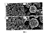
- Example 1 shows a scanning electron micrograph of the acetylene black-carbon nanotube microsphere composite material (a, b) and lithium carbon micron composite particles (c, d) obtained in Example 1.
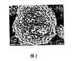
- Figure 2 is an enlarged scanning electron micrograph (magnification 20000) of Figure 1b.
- Fig. 3 shows the results of a half-cell cycle performance test conducted by the lithium carbon micron composite particles of Example 1 and lithium sheets, respectively, in a half-cell, at a current density of 0.5 mA cm -2 and a capacity of 0.5 mAh cm -2 .
- Example 4 shows the lithium carbon micron composite particles of Example 1, the lithium sheets are respectively composed of a half-cell, a current density of 0.5 mA cm -2 , and the electrode morphology after a cycle of 0.5 mAh cm -2 (a, b is Lithium carbon micron composite particles, c, d are lithium sheets).
- Fig. 5 is a graph showing the voltage-capacity curves of the lithium carbon microcomposite particles/lithium half-cells of Example 1 at different cycle times during the constant current charge and discharge test.
- Fig. 6 is a view showing the test results of the capacity retention ratio at different cycle times under the condition of 1 C rate for the lithium carbon micron composite particles of Example 1 and the lithium battery composed of lithium iron phosphate and lithium iron phosphate, respectively.
- Figure 7 shows a comparison of the microsphere materials formed separately without the carbon nanoparticles and the nanocarbon-containing particles, the left panel is the microsphere material obtained in Example 2, and the right panel is the microsphere material obtained in Example 1.
- Fig. 8 shows the results of a half-cell cycle performance test in which lithium-carbon micron composite particles and lithium sheets of Example 2 were respectively composed of half-cells at a current density of 0.5 mA cm -2 and a capacity of 0.5 mAh cm -2 .
- Figure 9 shows a scanning electron microscope (SEM) photograph of the lithium-carbon fiber microsphere composite of Example 5.
- Fig. 10 is a graph showing the constant current charge and discharge curve of the lithium-carbon fiber microsphere composite of Example 5 as a negative electrode.
- Fig. 11 is a view showing the test results of the half-cell cycle performance of the metal lithium-nickel skeleton carbon material-constituting half-cell of Example 6 under the conditions of a current density of 0.5 mA cm -2 and a capacity of 0.5 mAh cm -2 .
- Fig. 12 is a view showing the test results of the capacity retention ratio at different cycle times under the condition of 1 C rate for the full battery composed of the metal lithium-nickel skeleton carbon material of Example 6.
- Nano carbon particles - porous skeleton composite Nano carbon particles - porous skeleton composite:
- One aspect of the present invention provides a nanocarbon particle-porous skeleton composite comprising a porous framework material composed of a carbon-based porous microsphere material having a diameter of 1 to 100 ⁇ m or a porous metal material having an internal pore having a pore size distribution of a micrometer. And nanocarbon particles distributed in and on the pores of the porous framework material.
- the carbon-based porous microsphere material comprises at least one of carbon nanotube or carbon nanofiber microsphere material, graphite, mesocarbon microbeads, and porous activated carbon.
- the carbon nanotube or carbon nanofiber microsphere material is formed by intertwining a carbon nanotube or carbon nanofiber with one another, with a plurality of nanoscale pores on the interior and on the surface.
- Such microspheres have an approximately solid structure (like a wool-like structure), that is, the inside of the microspheres is filled with carbon nanotubes or carbon nanofibers, but nano-scale pores exist between the entangled agglomerated carbon nanotubes or carbon nanofibers, and these pores It can be used to hold nano carbon particles and metallic lithium particles.
- the carbon nanotube or carbon nanofiber microsphere material is spherical or spheroidal particles, and the average diameter may be 1 ⁇ m to 100 ⁇ m, preferably 1 ⁇ m to 25 ⁇ m; and the specific surface area may be 100 to 1500 m 2 /g. Preferably, it is 150 to 500 m 2 /g; and the pores contained in the microspheres may have a pore size distribution of from 1 to 200 nm, preferably from 1 to 50 nm.
- the microspheres containing nano carbon particles and the microspheres containing no carbon nanoparticles did not change significantly in the morphology, except that the pore volume decreased, for example, from 2.0 to 1.4 cm 3 g -1 .
- the carbon nanotube or carbon nanofiber microsphere material has at least any one of a microspherical solid aggregate structure, a spherical aggregate structure, a spheroidal aggregate structure, a porous spherical aggregate structure, and a doughnut-shaped aggregate structure.
- the carbon nanotubes include any one or a combination of two or more of multi-walled carbon nanotubes, double-walled carbon nanotubes, and single-walled carbon nanotubes, optionally passing through a surface.
- Functional processing The group modified on the surface of the carbon nanotube may be selected from, but not limited to, a group such as -COOH, -OH, -NH 2 or the like.
- the graphite, mesocarbon microbeads, and porous activated carbon are in the form of flakes, spheres, or spheroidal particles, and may have an average diameter of 50 ⁇ m to 500 ⁇ m, preferably 100 ⁇ m to 200 ⁇ m; and a specific surface area of 100 to 1000 m. 2 / g, preferably 100 to 500 m 2 /g; the pores contained may have a pore size distribution of 20 to 500 nm, preferably 20 to 100 nm.
- the porous metal material comprises at least one of porous copper, porous aluminum, porous zinc, porous iron, porous nickel, porous gold, and porous silver.
- the porous metal material may have pores having a pore size distribution of from 100 to 1000 ⁇ m, preferably from 100 to 500 ⁇ m, and a specific surface area of from 50 to 500 m 2 /g, preferably from 50 to 200 m 2 /g.
- the nanocarbon particles include at least one of carbon black (eg, Degussa carbon black), acetylene black, Ketjen black, Super High Conductivity Agent Super P, and Cabot BP2000.
- carbon black eg, Degussa carbon black
- acetylene black e.g., Ketjen black
- Super High Conductivity Agent Super P e.g., Cabot BP2000.
- the nanocarbon particles may have a size of from 1 to 500 nm, preferably from 50 to 200 nm.
- the content of the nanocarbon particles in the nanocarbon particle-porous skeleton composite relative to the porous skeleton may be 20 to 500 wt%, preferably 50 to 200 wt%.
- An aspect of the invention provides a method for preparing a nano carbon particle-porous skeleton composite material, comprising: dispersing carbon nanotubes or carbon nanofibers together with nano carbon particles in a solvent to form a dispersion, and then spray drying; or, The micron-sized porous graphite, mesocarbon microbeads, porous activated carbon or porous metal material are immersed in the nanocarbon particle solution, sonicated, and then dried.
- the nanocarbon particle-carbon nanotube or carbon nanofiber microsphere composite may be prepared by a spray drying method, for example, the preparation method may include the following steps:
- step B The dispersion obtained in the step A is sprayed through the nozzle of the spray dryer, and the inlet air temperature and the outlet air temperature are preset, and the solution is kept in a stirring state during the spraying process;
- Cooling that is, obtaining nano carbon particles-carbon nanotube/carbon nanofiber microsphere composite material.
- the mass ratio between the nanocarbon particles and the carbon nanotubes/carbon nanofibers in step A may be from 0.5:1 to 8:1, preferably from 0.5:1 to 5:1, more preferably 0.5:1. Until 2:1.
- nanocarbon particles and “carbon nanotubes/carbon nanofibers”, see the relevant description in the "Nanocarbon particles-porous skeleton composites” section above.
- the concentration of the carbon nanotubes/carbon nanofibers in the dispersion may be from 10 to 50 g/L, preferably from 10 to 15 g/L.
- the solvent employs an organic and/or inorganic liquid capable of uniformly dispersing carbon nanotubes/carbon nanofibers and nanocarbon particles, for example, water, ammonia, hydrochloric acid solution, ethanol, acetone, isopropanol. Any combination of one or more.
- an organic and/or inorganic liquid capable of uniformly dispersing carbon nanotubes/carbon nanofibers and nanocarbon particles, for example, water, ammonia, hydrochloric acid solution, ethanol, acetone, isopropanol. Any combination of one or more.
- the solvent may be a mixture of ethanol and water in a volume ratio of 1:10.
- the conditions of spray drying may include: an inlet air temperature of 150 to 250 ° C, an outlet air temperature of 75 ° C or higher, such as 75 to 150 ° C, or 90 ° C or higher; a preferred spray drying condition includes: The inlet air temperature is 190 to 210 ° C, and the outlet air temperature is 90 to 110 ° C.
- the spray rate at spray drying can range from 1 milliliter per minute to 100 liters per minute.
- the nanocarbon particle-porous framework composite is prepared by impregnation ultrasonication using micron-sized porous graphite, mesocarbon microbeads, porous activated carbon, or a porous metal material as the porous framework material.
- the immersion ultrasonic method may include immersing micron-sized porous graphite, mesophase carbon microspheres, porous activated carbon or porous metal material in a nano carbon particle solution, sonicating, and then drying.
- the nanocarbon particle solution comprises an aqueous solution of nanocarbon particles, or a solution in an ethanol solvent or a mixed solvent of ethanol and water.
- the concentration of the nanocarbon particles in the nanocarbon particle solution may range from 5 to 50 g/L, preferably from 10 to 30 g/L.
- One aspect of the present invention provides a metal lithium-carbon nanoparticle-porous skeleton composite material comprising the above-described nano carbon particle-porous skeleton composite material, and distributed in pores of the nano carbon particle-porous skeleton composite material and Metallic lithium on the surface,
- the nano-carbon particle-porous skeleton composite material is used as a skeleton-supporting metal lithium, and the metallic lithium exists in the form of a simple substance in the pores or on the surface thereof (mainly inside the pores, and the surface has less metallic lithium).
- the mass of metallic lithium is from 1% to 95%, preferably from 10% to 70%, more preferably from 20% to 70%, by total mass of the composite.
- One aspect of the present invention provides a method of preparing a metal lithium-carbon nanoparticle-porous skeleton composite comprising: mixing molten metal lithium with the above-described nanocarbon particle-porous skeleton composite, and then cooling.
- the mixing of the molten metallic lithium with the nanocarbon particle-carbon based porous microsphere composite can include agitating and mixing the metallic lithium with the carbon-based porous microsphere material under heating.
- the agitation mixing can include a pre-stirring step and a rapid agitation step, wherein the pre-stirring step includes metal lithium and nano-carbon particles-porous at a relatively low temperature (eg, about 200 ° C - 230 ° C)
- a relatively low temperature eg, about 200 ° C - 230 ° C
- the mixture of skeleton composites is stirred at a low speed (for example, about 50 rpm to 100 rpm) for a short period of time (for example, 1-5 minutes), and the rapid stirring step is included at a relatively high temperature (for example, about 230 ° C - 300 °C) Rapid agitation (for example, about 150 rpm to 1000 rpm, preferably 200 rpm to 800 rpm).
- the mixing of the molten metallic lithium with the nanocarbon particulate-porous metal composite may include the step of immersing the nanocarbon particulate-porous metal composite in molten metallic lithium.
- the mass of metallic lithium is from 1% to 95%, preferably from 10% to 70%, more preferably from 20% to 70%, by total mass of the composite.
- One aspect of the present invention provides an electrode comprising the above-described metal lithium-carbon nanoparticle-porous skeleton composite material as an electrode material.
- the metallic lithium-nanocarbon particle-porous framework composite can be used as an active material for a battery negative electrode or (in the case of a porous metal skeleton) directly used as an electrode.
- One aspect of the invention provides an electrochemical energy storage device comprising the electrodes described above.
- the electrochemical energy storage device is an electrochemical cell that acts as a battery negative electrode.
- the electrochemical cell comprises a lithium battery, a metal lithium-oxide battery, a metal lithium-sulfur secondary battery, or a metal lithium-air battery.
- the electrochemical energy storage device is a supercapacitor that acts as one electrode sheet for a supercapacitor.
- the lithium-nanocarbon particle-porous skeleton composite material provided by the invention when applied to an electrochemical battery, the nano carbon particles present in the material can better conduct lithium ions during battery cycling, thereby inhibiting metal lithium branches
- the formation of crystals improves the safety of the battery and also improves the cycle stability of the battery.
- porous skeleton is a carbon-based porous microsphere material having a diameter of 1 to 100 ⁇ m, or a porous metal material having internal pores having a pore size distribution of a micrometer,
- the nanocarbon particles are distributed in and on the pores of the carbon-based porous microsphere material or the porous metal material.
- Embodiment 2 is the nano carbon particle-porous skeleton composite material according to Embodiment 1, wherein the carbon-based porous microsphere material comprises carbon nanotube or carbon nanofiber microsphere material, graphite, mesophase carbon microsphere And at least one of porous activated carbon, wherein the carbon nanotube or carbon nanofiber microsphere material is formed by intertwining a carbon nanotube or a carbon nanofiber, and the inside of the microsphere is filled with carbon nanotubes or carbon nanofibers, and the inside And a large number of nanoscale pores on the surface;
- the porous metal material includes at least one of porous copper, porous aluminum, porous zinc, porous iron, porous nickel, porous gold, and porous silver.
- the nano carbon particles include at least one of carbon black, acetylene black, ketjen black, super high conductivity agent Super P, and Cabot BP2000.
- the third embodiment is the nano carbon particle-porous skeleton composite material according to the embodiment 1 or 2, wherein the nano carbon particles may have a size of 1 to 500 nm, preferably 50 to 200 nm.
- nano carbon particle-porous skeleton composite according to any one of the embodiments 1 to 3, wherein the content of the nano carbon particles relative to the porous skeleton is 20 to 500 wt%.
- nano carbon particle-porous skeleton composite material according to any one of the embodiments 2-4, wherein the carbon nanotube or carbon nanofiber microsphere material has a specific surface area of 100 to 1500 m 2 / g;
- the carbon nanotube or carbon nanofiber microsphere material has a pore diameter of 1 to 200 nm;
- the carbon nanotube or carbon nanofiber microsphere material has at least one of a microscopic spherical solid aggregate structure, a spherical aggregate structure, a spherical aggregate structure, a porous spherical aggregate structure, and a doughnut aggregate structure;
- the carbon nanotubes include any one or a combination of two or more of multi-walled carbon nanotubes, double-walled carbon nanotubes, and single-walled carbon nanotubes, optionally subjected to surface functionalization deal with.
- micron-sized porous graphite, mesocarbon microbeads, porous activated carbon or porous metal material are immersed in a nanocarbon particle solution, sonicated, and then dried.
- Embodiment 7 is the method of embodiment 6, wherein the method of spray drying the carbon nanotubes or carbon nanofibers together with the nano carbon particles comprises the steps of:
- step B The dispersion obtained in the step A is sprayed through the nozzle of the spray dryer, and the inlet air temperature and the outlet air temperature are preset, and the solution is kept in a stirring state during the spraying process;
- Cooling that is, obtaining nano carbon particles-carbon nanotube/carbon nanofiber microsphere composite material.
- step A is a method according to a specific embodiment 7, wherein the mass ratio between the nano carbon particles and the carbon nanotubes/carbon nanofibers in step A is from 0.5:1 to 8:1;
- the concentration of the carbon nanotubes/carbon nanofibers in the dispersion is 10 to 50 g/L;
- the dispersing solvent includes any one or a combination of water, ammonia water, hydrochloric acid solution, ethanol, acetone, and isopropyl alcohol.
- inlet air temperature is 190 to 210 ° C
- outlet air temperature is 90 to 110 ° C.
- the spray rate is from 1 ml/min to 100 l/min.
- Embodiment 8 is the method of embodiment 6, wherein the nano carbon particle solution comprises an aqueous solution of nano carbon particles;
- the concentration of the nano carbon particles in the nano carbon particle solution is 5 to 50 g/L.
- the embodiment 10 is a metal lithium-carbon nanoparticle-porous skeleton composite material, comprising the nano carbon particle-porous skeleton composite material according to any one of embodiments 1 to 5, and distributed to the nanocarbon Metallic lithium in and on the pores of the particle-porous framework composite.
- Embodiment 11 is the lithium-nano carbon particle-porous skeleton composite material according to Embodiment 10, wherein the mass of the metal lithium is 1% to 95% of the total mass of the lithium-nano carbon particle-porous skeleton composite material. .
- FIG. 12 is a method of preparing a metal lithium-carbon nanoparticle-porous skeleton composite material, comprising: compounding molten lithium metal with the nano carbon particle-porous skeleton according to any one of embodiments 1-5. The materials are mixed and then cooled.
- Embodiment 13 is the method of embodiment 11, wherein the mixing of the molten metallic lithium with the nanocarbon particle-carbon based porous microsphere composite comprises:
- the nanocarbon particle-porous metal composite is immersed in molten metal lithium.
- Embodiment 14 is the method of embodiment 13, wherein the agitation mixing comprises a pre-stirring step and a rapid stirring step, wherein the pre-stirring step comprises metal lithium and nano-carbon particles-porous skeleton composite at 200 ° C to 230 ° C
- the mixture is stirred at 50 rpm to 100 rpm for 1-5 minutes, and the rapid stirring step includes rapid stirring at 230 rpm to 1000 ° C at 150 rpm to 1000 rpm.
- Embodiment 15 is an electrode comprising the lithium-nanocarbon particle-porous skeleton composite material described in Embodiment 10 or 11.
- DETAILED DESCRIPTION 16 is an electrochemical energy storage device comprising the electrode of embodiment 15; the electrochemical energy storage device comprising an electrochemical cell or a supercapacitor.
- Embodiment 17 is the electrochemical energy storage device according to Embodiment 16, wherein the electrochemical cell comprises a lithium battery, a metal lithium-oxide battery, a metal lithium-sulfur secondary battery, or a metal lithium-air battery.
- an acetylene black-carbon nanotube microsphere composite material was obtained.
- the composite was subjected to nitrogen adsorption desorption test, and the specific surface area of the microspheres was 103 m 2 /g, and the average pore diameter was 15.2 nm.
- Example 1 shows a scanning electron micrograph of the acetylene black-carbon nanotube microsphere composite material (a, b) and lithium carbon micron composite particles (c, d) obtained in Example 1.
- FIG. 2 is an enlarged scanning electron micrograph (magnification 20000) of FIG. 1b, in which the particulate matter in the circle is a carbon nanoparticle (acetylene black nanoparticle).
- the left figure shows the cycle curve when using lithium carbon micron composite particles
- the right picture shows the lithium film cycle curve.
- the lithium carbon micron composite particles exhibit a small polarization voltage at the beginning compared with the lithium metal sheet, indicating that the material has a large specific surface area, and the post-cycle polarization voltage is There are no major changes that demonstrate the stability of the material structure and the surface solid electrolyte interface (SEI) layer during the cycle.
- SEI surface solid electrolyte interface
- Figure 4 shows lithium-carbon micron composite particles, lithium sheets respectively composed of half-cells, 0.5 mA cm -2 current density, 0.5 mAh cm -2 capacity after 200 cycles of electrode morphology (a, b is lithium carbon micro-composite Particles, c, d are lithium flakes).
- a, b is lithium carbon micro-composite Particles, c, d are lithium flakes.
- the lithium-carbon micron composite material retains the grain structure after the cycle, which proves the stability of the material structure during the cycle.
- Figure 5 shows the voltage-capacity curve (current magnitude of 0.74 mA/cm -2 ) for lithium carbon micron composite particles/lithium half cells at different cycle times during constant current charge and discharge testing.
- the capacity of the lithium carbon micron composite particles is basically unchanged after 500 cycles of 1C rate, indicating that the surface SEI layer is stable when the material is recycled, and metal lithium is not always consumed.
- a lithium-carbon micro-composite particle and a lithium battery are respectively combined with a lithium iron phosphate composite battery (20 to 40 mg of lithium carbon micro-composite particles are pressed on a copper foam having a diameter of 1.5 cm and a thickness of 1 mm, and the material is used as a negative electrode; Iron lithium (LFP) electrode pole piece (produced by Suzhou Naxin New Energy Technology Co., Ltd., surface density is 0.7mAh/cm 2 ) as a positive electrode composed of 2025 button battery), at 1C rate (positive and negative electrode capacities are 1.4mAh and Under the condition of 40 mAh), the capacity retention rate under different cycle times was measured.
- Figure 6 shows the test results. As shown in Fig.
- a carbon nanotube microsphere material was prepared in the same manner as in Example 1 except that acetylene black was not used.
- the microsphere material had a specific surface area of 151 m 2 /g and an average pore diameter of 18.7 nm.
- Figure 7 shows a comparison of the microsphere materials formed without the nanocarbon particles (left) and the nanocarbon particles (right). It can be seen from the figure that the morphology of the microsphere material did not change significantly after the addition of carbon nanoparticles.
- lithium carbon micron composite particles were prepared in the same manner as in Example 1, and the mass percentage of lithium in the lithium carbon micron composite particles was 40.4%.
- the lithium carbon micron composite particles and the lithium sheets obtained above were respectively made into a half-cell, and the half-cell cycle performance test was carried out under the condition of a current density of 0.5 mA cm -2 and a capacity of 0.5 mAh cm -2 .
- Figure 8 shows the results of the half-cell cycle performance test. As shown in FIG. 8, the lithium carbon micron composite particles of Example 2 were used to form a half-cell. As the number of cycles increased, the polarization voltage of the sample continued to increase, indicating that the surface of the sample surface gradually thickened due to the lithium metal. Caused by continuous reaction with the electrolyte.
- the nanocarbon particle-porous skeleton composite material and the lithium carbon micron composite particles were prepared in the same manner as in Example 1 except that the acetylene black in Example 1 was replaced with Ketjen black ECP 600JD.
- the mass percentage of lithium in the lithium carbon micron composite particles was 60.0%.
- the morphology and performance test results of the obtained materials were similar to those of Example 1.
- the nanocarbon particle-porous skeleton composite material and the lithium carbon micron composite particles were prepared in the same manner as in Example 1 except that the acetylene black in Example 1 was replaced with Dexter carbon black (Printex XE-2).
- the mass percentage of lithium in the lithium carbon micron composite particles was 51.8%.
- the morphology and performance test results of the obtained materials were similar to those of Example 1.
- the morphology is similar to the acetylene black-carbon nanotube microsphere composite of Example 1.
- the composite was subjected to nitrogen adsorption desorption test, and the specific surface area of the microspheres was 98 m 2 /g, and the average pore diameter was 13.1 nm.
- Figure 10 shows a constant current charge and discharge curve of a lithium-carbon fiber microsphere composite as a negative electrode. It can be seen from the figure that the lithium-carbon fiber microsphere composite material has a small polarization voltage at the beginning, indicating that the material has a large specific surface area, which can greatly reduce the current density and effectively inhibit the formation of lithium branch crystals. Avoid battery safety hazards due to dendrite short circuit, and thus more likely to be applied in practical high energy density battery systems.
- a porous metal nickel (pore size distribution of 100-500 ⁇ m) skeleton material having a diameter of 1.5 cm and a thickness of 500-1000 ⁇ m was placed in 100 mL of an aqueous solution of acetylene black (Alfa Aesar) at a concentration of 20 g/L, and then the solution was Ultrasonic dispersion treatment was carried out for 1 h.
- the obtained mixture was allowed to stand in an oven at 80 ° C for 24 hours to obtain a porous metal nickel skeleton material containing nano carbon particles.
- a porous metal nickel skeleton material containing nano-sized carbon particles is immersed in molten metal lithium to obtain a metal lithium-nickel skeleton material.
- the mass percentage of lithium in the metallic lithium-nickel skeleton material was 50.0% [(mass of metallic lithium-nickel skeleton material - mass of metallic nickel skeleton) / mass of metallic lithium-nickel skeleton material].
- the lithium metal-nickel skeleton carbon material was composed of a half-cell, a current density of 0.5 mA cm -2 , and a capacity of 0.5 mAh cm -2 , and the half-cell cycle performance was tested.
- the results are shown in FIG. It can be seen from Fig. 11 that the polarization voltage is basically unchanged after 200 cycles of the sample, and the slight increase is caused by the gradual thickening of the surface SEI layer; and the stability of the capacity and coulombic efficiency under the full battery test condition further indicates the material structure and surface. The stability of the SEI layer.
- a full battery composed of a metal lithium-nickel skeleton carbon material and lithium iron phosphate was measured for capacity retention at different cycle times under a condition of 1 C rate, and the results are shown in FIG.
Landscapes
- Chemical & Material Sciences (AREA)
- Engineering & Computer Science (AREA)
- Chemical Kinetics & Catalysis (AREA)
- Electrochemistry (AREA)
- General Chemical & Material Sciences (AREA)
- Materials Engineering (AREA)
- Power Engineering (AREA)
- Organic Chemistry (AREA)
- Manufacturing & Machinery (AREA)
- Nanotechnology (AREA)
- Inorganic Chemistry (AREA)
- Microelectronics & Electronic Packaging (AREA)
- Composite Materials (AREA)
- Crystallography & Structural Chemistry (AREA)
- Mechanical Engineering (AREA)
- Metallurgy (AREA)
- Ceramic Engineering (AREA)
- Physics & Mathematics (AREA)
- Condensed Matter Physics & Semiconductors (AREA)
- General Physics & Mathematics (AREA)
- Structural Engineering (AREA)
- Battery Electrode And Active Subsutance (AREA)
- Electric Double-Layer Capacitors Or The Like (AREA)
- Cell Electrode Carriers And Collectors (AREA)
Abstract
Description
Claims (18)
- [根据细则26改正14.11.2017]
一种纳米碳颗粒-多孔骨架复合材料,其特征在于所述多孔骨架是直径1-100微米的碳基多孔微球材料,或是具有微米尺度孔径分布的内部孔隙的多孔金属材料,所述纳米碳颗粒分布于所述碳基多孔微球材料或所述多孔金属材料的孔隙内及表面上。 - [根据细则26改正14.11.2017]
根据权利要求1所述的纳米碳颗粒-多孔骨架复合材料,其特征在于所述碳基多孔微球材料包括碳纳米管或碳纳米纤维微球材料、石墨、中间相碳微球和多孔活性炭中的至少一种,其中所述碳纳米管或碳纳米纤维微球材料由碳纳米管或碳纳米纤维相互交缠团聚而形成,微球内部充满碳纳米管或碳纳米纤维,内部和表面上具有大量纳米尺度孔隙;和/或,所述多孔金属材料包括多孔铜,多孔铝,多孔锌,多孔铁,多孔镍,多孔金和多孔银中的至少一种,和/或,所述纳米碳颗粒包括炭黑,乙炔黑,科琴黑,特密高导电剂Super P,卡博特BP2000中的至少一种。 - [根据细则26改正14.11.2017]
根据权利要求1或2所述的纳米碳颗粒-多孔骨架复合材料,其特征在于纳米碳颗粒的尺寸可以为1-500nm,优选50-200纳米。 - [根据细则26改正14.11.2017]
根据权利要求1-3中任一项所述的纳米碳颗粒-多孔骨架复合材料,其特征在于所述纳米碳颗粒相对于所述多孔骨架的含量为20-500wt%。 - [根据细则26改正14.11.2017]
根据权利要求2-4中任一项所述的纳米碳颗粒-多孔骨架复合材料,其特征在于所述碳纳米管或碳纳米纤维微球材料的比表面积为100~1500m2/g;和/或,所述碳纳米管或碳纳米纤维微球材料所含孔隙的孔径为1~200nm;和/或,所述碳纳米管或碳纳米纤维微球材料至少具有微小球状实体聚集结构、球形聚集结构、类球形聚集结构、多孔球形聚集结构和面包圈形聚集结构中的任意一种;和/或,所述碳纳米管包括多壁碳纳米管、双壁碳纳米管和单壁碳纳米管中的任意一种或两种以上的组合,所述碳纳米管任选经过表面功能化处理。 - [根据细则26改正14.11.2017]
一种制备权利要求1-5中任一项所述的纳米碳颗粒-多孔骨架复合材料的方法,包括:将碳纳米管或碳纳米纤维与纳米碳颗粒一起分散于溶剂中形成分散液,然后喷雾干燥;或者,将微米级多孔石墨、中间相碳微球、多孔活性炭或者多孔金属材料浸渍在纳米碳颗粒溶液中,超声处理,然后干燥。 - [根据细则26改正14.11.2017]
根据权利要求6所述的方法,其特征在于将碳纳米管或碳纳米纤维与纳米碳颗粒一起喷雾干燥的方法包括如下步骤:A、将碳纳米管/碳纳米纤维和纳米碳颗粒通过超声处理分散到分散溶剂(不含表面活性剂)中,获得分散液;B、将步骤A中获得的分散液通过喷雾干燥机的喷嘴喷出,预设定进风温度和出风温度,喷雾过程中保持溶液为搅拌状态;C、冷却,即获得纳米碳颗粒-碳纳米管/碳纳米纤维微球复合材料。 - [根据细则26改正14.11.2017]
根据权利要求7所述的方法,其特征在于步骤A中纳米碳颗粒与碳纳米管/碳纳米纤维之间的质量比0.5:1至8:1;和/或,碳纳米管/碳纳米纤维在分散液中的浓度为10~50g/L;和/或,分散溶剂包括水、氨水、盐酸溶液、乙醇、丙酮、异丙醇的任意一种或多种的组合。 - [根据细则26改正14.11.2017]
根据权利要求7或8所述的方法,其特征在于进风温度为190~210℃,出风温度为90~110℃,和/或,喷雾速度为1毫升/分钟至100升/分钟。 - [根据细则26改正14.11.2017]
根据权利要求6所述的方法,其特征在于所述纳米碳颗粒溶液包括纳米碳颗粒水溶液;和/或,纳米碳颗粒在纳米碳颗粒溶液中的浓度为5~50g/L。 - [根据细则26改正14.11.2017]
一种金属锂-纳米碳颗粒-多孔骨架复合材料,其特征在于包括权利要求1-5中任一项所述的纳米碳颗粒-多孔骨架复合材料,和分布于所述纳米碳颗粒-多孔骨架复合材料的孔隙内及表面上的金属锂。 - [根据细则26改正14.11.2017]
根据权利要求10所述的锂-纳米碳颗粒-多孔骨架复合材料,其特征在于金属锂的质量为所述锂-纳米碳颗粒-多孔骨架复合材料整体质量的1%~95%。 - [根据细则26改正14.11.2017]
一种制备金属锂-纳米碳颗粒-多孔骨架复合材料的方法,包括:将熔融的金属锂与权利要求1-5中任一项所述的纳米碳颗粒-多孔骨架复合材料混合,然后冷却。 - [根据细则26改正14.11.2017]
根据权利要求12所述的方法,其特征在于熔融的金属锂与纳米碳颗粒-碳基多孔微球复合材料的混合包括:将金属锂与碳基多孔微球材料在加热下搅拌混合;或者将纳米碳颗粒-多孔金属复合材料浸入熔融金属锂中。 - [根据细则26改正14.11.2017]
根据权利要求13所述的方法,其特征在于搅拌混合包括预搅拌步骤和快速搅拌步骤,其中预搅拌步骤包括在200℃-230℃将金属锂与纳米碳颗粒-多孔骨架复合材料的混合物以50转/ 分钟-100转/分钟搅拌1-5分钟,快速搅拌步骤包括在230℃-300℃以150转/分钟-1000转/分钟进行快速搅拌。 - [根据细则26改正14.11.2017]
一种电极,其包含权利要求10或11所述的锂-纳米碳颗粒-多孔骨架复合材料。 - [根据细则26改正14.11.2017]
一种电化学储能装置,其包括权利要求15所述的电极;所述电化学储能装置包括电化学电池或超级电容器。 - [根据细则26改正14.11.2017]
根据权利要求16的电化学储能装置,其特征在于电化学电池包括锂电池、金属锂-氧化物电池、金属锂-硫二次电池或金属锂-空气电池。
Priority Applications (6)
| Application Number | Priority Date | Filing Date | Title |
|---|---|---|---|
| JP2019560436A JP2020509566A (ja) | 2017-07-26 | 2017-10-11 | ナノカーボン粒子−多孔質骨格複合材料、その金属リチウム複合物、それらの調製方法及び応用 |
| EP17919284.4A EP3660963A4 (en) | 2017-07-26 | 2017-10-11 | POROUS CARBON NANOPARTICLE FRAMEWORK COMPOSITE MATERIAL, LITHIUM METAL COMPLEX MADE OF POROUS CARBON NANOPARTICLE FRAMEWORK COMPOSITE MATERIAL, MANUFACTURING METHODS FOR IT AND APPLICATIONS THEREOF |
| KR1020217020010A KR20210084657A (ko) | 2017-07-26 | 2017-10-11 | 탄소 나노입자-다공성 프레임워크 복합 재료, 탄소 나노입자-다공성 프레임워크 복합 재료와 리튬 금속의 복합체, 이의 제조 방법 및 이의 용도 |
| US16/477,791 US20200123008A1 (en) | 2017-07-26 | 2017-10-11 | Carbon nanoparticle-porous skeleton composite material, its composite with lithium metal, and their preparation methods and use |
| KR1020197022378A KR20190099062A (ko) | 2017-07-26 | 2017-10-11 | 탄소 나노입자-다공성 프레임워크 복합 재료, 탄소 나노입자-다공성 프레임워크 복합 재료와 리튬 금속의 복합체, 이의 제조 방법 및 이의 용도 |
| US17/733,367 US11866332B2 (en) | 2017-07-26 | 2022-04-29 | Carbon nanoparticle-porous skeleton composite material, its composite with lithium metal, and their preparation methods and use |
Applications Claiming Priority (2)
| Application Number | Priority Date | Filing Date | Title |
|---|---|---|---|
| CN201710617358.2 | 2017-07-26 | ||
| CN201710617358.2A CN109309203A (zh) | 2017-07-26 | 2017-07-26 | 纳米碳颗粒-多孔骨架复合材料、其金属锂复合物、它们的制备方法及应用 |
Related Child Applications (2)
| Application Number | Title | Priority Date | Filing Date |
|---|---|---|---|
| US16/477,791 A-371-Of-International US20200123008A1 (en) | 2017-07-26 | 2017-10-11 | Carbon nanoparticle-porous skeleton composite material, its composite with lithium metal, and their preparation methods and use |
| US17/733,367 Continuation US11866332B2 (en) | 2017-07-26 | 2022-04-29 | Carbon nanoparticle-porous skeleton composite material, its composite with lithium metal, and their preparation methods and use |
Publications (1)
| Publication Number | Publication Date |
|---|---|
| WO2019019412A1 true WO2019019412A1 (zh) | 2019-01-31 |
Family
ID=65039359
Family Applications (1)
| Application Number | Title | Priority Date | Filing Date |
|---|---|---|---|
| PCT/CN2017/105676 Ceased WO2019019412A1 (zh) | 2017-07-26 | 2017-10-11 | 纳米碳颗粒-多孔骨架复合材料、其金属锂复合物、它们的制备方法及应用 |
Country Status (6)
| Country | Link |
|---|---|
| US (2) | US20200123008A1 (zh) |
| EP (1) | EP3660963A4 (zh) |
| JP (1) | JP2020509566A (zh) |
| KR (2) | KR20210084657A (zh) |
| CN (1) | CN109309203A (zh) |
| WO (1) | WO2019019412A1 (zh) |
Cited By (16)
| Publication number | Priority date | Publication date | Assignee | Title |
|---|---|---|---|---|
| CN112409028A (zh) * | 2020-10-28 | 2021-02-26 | 桂林电子科技大学 | 一种CC-NiO-CuCoS复合材料及其制备方法和应用 |
| CN112736251A (zh) * | 2020-12-30 | 2021-04-30 | 电子科技大学 | 含有锂合金骨架网络的三维多孔材料、其复合锂负极材料及制备方法 |
| CN112771693A (zh) * | 2020-04-23 | 2021-05-07 | 宁德时代新能源科技股份有限公司 | 三维复合金属锂负极和金属锂电池与装置 |
| CN112897646A (zh) * | 2021-01-19 | 2021-06-04 | 山东欣远新材料科技有限公司 | 一种掺硼金刚石薄膜电极泡沫金属基体的制备方法 |
| US11127942B2 (en) * | 2019-10-25 | 2021-09-21 | Lyten, Inc. | Systems and methods of manufacture of carbon based structures incorporated into lithium ion and lithium sulfur (li s) battery electrodes |
| US11309545B2 (en) | 2019-10-25 | 2022-04-19 | Lyten, Inc. | Carbonaceous materials for lithium-sulfur batteries |
| US11342561B2 (en) | 2019-10-25 | 2022-05-24 | Lyten, Inc. | Protective polymeric lattices for lithium anodes in lithium-sulfur batteries |
| US11398622B2 (en) | 2019-10-25 | 2022-07-26 | Lyten, Inc. | Protective layer including tin fluoride disposed on a lithium anode in a lithium-sulfur battery |
| CN114824218A (zh) * | 2022-04-29 | 2022-07-29 | 浙江碳一新能源有限责任公司 | 锂金属复合材料及其改性材料以及它们的制法和电池 |
| CN114824184A (zh) * | 2021-01-29 | 2022-07-29 | 清华大学 | 锂金属阳极及其制备方法 |
| US11462741B2 (en) | 2017-07-26 | 2022-10-04 | China Energy Cas Technology Co., Ltd. | Metallic lithium-skeleton carbon composite material having a hydrophobic cladding layer, preparation method and use thereof |
| US11489161B2 (en) | 2019-10-25 | 2022-11-01 | Lyten, Inc. | Powdered materials including carbonaceous structures for lithium-sulfur battery cathodes |
| US11735745B2 (en) | 2021-06-16 | 2023-08-22 | Lyten, Inc. | Lithium-air battery |
| US11901580B2 (en) | 2020-01-10 | 2024-02-13 | Lyten, Inc. | Selectively activated metal-air battery |
| US12126024B2 (en) | 2019-10-25 | 2024-10-22 | Lyten, Inc. | Battery including multiple protective layers |
| US12255309B2 (en) | 2021-06-16 | 2025-03-18 | Lyten, Inc. | Lithium-air battery |
Families Citing this family (26)
| Publication number | Priority date | Publication date | Assignee | Title |
|---|---|---|---|---|
| KR102893938B1 (ko) * | 2019-11-07 | 2025-12-01 | 한국전기연구원 | 리튬-황 전지용 전극 및 그 제조방법 |
| CN112909250B (zh) * | 2019-11-19 | 2022-04-26 | 中能中科(天津)新能源科技有限公司 | 碳材料微球、锂碳粉及其制备方法和应用 |
| CN113036094A (zh) * | 2019-12-09 | 2021-06-25 | 北京小米移动软件有限公司 | 金属钠多孔碳复合材料及其制备方法和电池 |
| CN110970229B (zh) * | 2019-12-27 | 2020-11-06 | 中国地质大学(北京) | NiCo2S4@中间相炭微球/碳纳米管复合材料及其制备方法与应用 |
| JP7008737B2 (ja) * | 2020-03-13 | 2022-01-25 | 本田技研工業株式会社 | リチウムイオン二次電池用電極、およびリチウムイオン二次電池 |
| CN111470491B (zh) * | 2020-04-13 | 2023-05-05 | 北京石墨烯研究院有限公司 | 碳质杂化粉体及其制备方法 |
| CN113594425B (zh) * | 2020-04-30 | 2022-12-27 | 中能中科(天津)新能源科技有限公司 | 复合碳骨架材料、锂碳材料及其制备方法和应用 |
| CN111725480A (zh) * | 2020-06-29 | 2020-09-29 | 珠海冠宇电池股份有限公司 | 复合形状记忆合金负极及其制备方法和锂电池 |
| CN111755261A (zh) * | 2020-07-09 | 2020-10-09 | 浙江奚态生物科技有限公司 | 一种掺银纳米线的纳米碳球电极材料的制备方法 |
| JP7497037B2 (ja) * | 2020-09-10 | 2024-06-10 | 国立研究開発法人物質・材料研究機構 | 空気電池の正極用多孔炭素膜電極、及びそれを用いた空気電池 |
| CN114400302B (zh) * | 2021-02-10 | 2023-05-09 | 北京卫蓝新能源科技有限公司 | 多孔碳微球及其制备方法碳锂复合材料、负极和锂金属电池 |
| WO2022197068A1 (en) * | 2021-03-15 | 2022-09-22 | Vitzrocell Co. Ltd. | Method of manufacturing anode electrode for lithium metal battery using irradiation of photoelectromagnetic energy and anode electrode for lithium metal battery |
| JP7674122B2 (ja) * | 2021-03-23 | 2025-05-09 | Tdk株式会社 | リチウムイオン二次電池用正極及びリチウムイオン二次電池 |
| CN113135558B (zh) * | 2021-04-19 | 2023-03-14 | 中国计量大学 | 一种基于多孔碳球的光热材料及其制备方法 |
| US20230053335A1 (en) * | 2021-08-18 | 2023-02-23 | Evoq Nano, Inc. | Electrolyte and electrode paste for lithium-ion battery, lithium-ion battery, and method of manufacturing lithium-ion battery with enhanced performance |
| CN115763794A (zh) * | 2021-09-02 | 2023-03-07 | 天津中能锂业有限公司 | 具有亲锂性修饰层的网络骨架材料与金属锂的复合物及其制备方法 |
| CN114335540B (zh) * | 2021-12-29 | 2023-03-21 | 北京卫蓝新能源科技有限公司 | 一种亲锂碳骨架复合材料及其制备方法和应用 |
| CN114784281A (zh) * | 2022-05-19 | 2022-07-22 | 清华大学山西清洁能源研究院 | 固态电池的复合锂负极及其制备方法、固态电池 |
| CN115044814A (zh) * | 2022-05-20 | 2022-09-13 | 同济大学 | 一种具有磁性的金属基复合材料及其制备方法与应用 |
| CN115394983A (zh) * | 2022-08-26 | 2022-11-25 | 中国科学技术大学 | 一种非晶合金颗粒/多孔碳复合骨架材料、其制备方法及应用 |
| CN118472191B (zh) * | 2023-02-09 | 2026-01-13 | 宁德时代新能源科技股份有限公司 | 复合活性材料和相关的二次电池和用电装置 |
| CN116314736B (zh) * | 2023-03-17 | 2025-09-05 | 深圳市研一新材料有限责任公司 | 一种锂复合材料及其制备方法与应用 |
| CN118825211A (zh) * | 2023-04-19 | 2024-10-22 | 溧阳天目先导电池材料科技有限公司 | 一种高性能正极材料及其制备方法和应用 |
| CN118231669B (zh) * | 2024-05-24 | 2024-08-06 | 广州巨湾技研有限公司 | 一种自支撑无锂负极片及其制备方法和锂电池 |
| CN118380570B (zh) * | 2024-06-19 | 2024-10-11 | 比亚迪股份有限公司 | 一种含锂磷酸盐材料、锂离子电池正极及制备方法与应用 |
| CN120727838B (zh) * | 2025-09-01 | 2025-11-11 | 杭州德海艾科能源科技有限公司 | 一种碳球改性石墨毡电极及其制备方法与应用 |
Citations (6)
| Publication number | Priority date | Publication date | Assignee | Title |
|---|---|---|---|---|
| CN101397652A (zh) * | 2008-10-31 | 2009-04-01 | 华东师范大学 | 一种金属微纤-纳米碳复合材料及制备方法 |
| CN105779804A (zh) * | 2016-03-21 | 2016-07-20 | 中南大学 | 一种泡沫骨架结构增强金属基复合材料及制备方法 |
| CN106033815A (zh) * | 2015-03-18 | 2016-10-19 | 中国科学院苏州纳米技术与纳米仿生研究所 | 锂硫电池正极、其制备方法及应用 |
| WO2017029692A1 (en) * | 2015-08-18 | 2017-02-23 | Nec Corporation | Porous Graphene Coated Oxygen-Containing Carbon Material for High Capacity and Fast Chargeable Anode of Lithium Ion Battery |
| CN106684342A (zh) * | 2015-11-11 | 2017-05-17 | 中国科学院苏州纳米技术与纳米仿生研究所 | 硅-碳纳米管微球、其金属锂复合物与其制备方法及应用 |
| CN106711456A (zh) * | 2015-11-12 | 2017-05-24 | 中国科学院苏州纳米技术与纳米仿生研究所 | 钝化的金属锂-碳骨架复合材料、其制备方法与应用 |
Family Cites Families (19)
| Publication number | Priority date | Publication date | Assignee | Title |
|---|---|---|---|---|
| JPH02227966A (ja) | 1989-02-28 | 1990-09-11 | Matsushita Electric Ind Co Ltd | 密閉形アルカリ蓄電池とその負極の製造法 |
| EP1256996A4 (en) | 2000-12-27 | 2008-01-23 | Mitsubishi Chem Corp | LITHIUM SECONDARY ELEMENT |
| JP2005142004A (ja) * | 2003-11-06 | 2005-06-02 | Sanyo Electric Co Ltd | 非水電解質二次電池 |
| CN1770515B (zh) * | 2005-08-22 | 2010-05-12 | 中国科学院成都有机化学有限公司 | 一种锂离子二次电池正极、负极材料导电剂及其制备方法 |
| US8945431B2 (en) | 2008-07-15 | 2015-02-03 | Universität Duisburg-Essen | Intercalation of silicon and/or tin into porous carbon substrates |
| CA2724307A1 (fr) | 2010-12-01 | 2012-06-01 | Hydro-Quebec | Batterie lithium-air |
| CN102437313A (zh) * | 2011-12-08 | 2012-05-02 | 中国电子科技集团公司第十八研究所 | 一种大功率金属锂电池用负电极 |
| JP2013135223A (ja) | 2011-12-23 | 2013-07-08 | Samsung Electro-Mechanics Co Ltd | 電極活物質/導電材の複合体及びその製造方法並びにこれを含む電気化学キャパシタ |
| US8828533B2 (en) * | 2012-01-12 | 2014-09-09 | Ut-Battelle, Llc | Mesoporous carbon materials |
| US8932764B2 (en) | 2012-02-28 | 2015-01-13 | Sila Nanotechnologies, Inc. | Core-shell composites for sulfur-based cathodes in metal-ion batteries |
| US9306207B2 (en) * | 2012-12-28 | 2016-04-05 | Hyundai Motor Company | Method of fabricating sulfur-infiltrated mesoporous conductive nanocomposites for cathode of lithium-sulfur secondary battery |
| EP3133047B8 (en) * | 2014-03-21 | 2020-07-22 | Suzhou Institute of Nano-tech and Nano-bionics (SINANO) Chinese Academy of Sciences | Lithium metal-skeleton carbon composite and preparation method therefor, negative electrode, and battery |
| CN104925778B (zh) * | 2014-03-21 | 2017-05-03 | 中国科学院苏州纳米技术与纳米仿生研究所 | 碳纳米管微球及其制备方法与应用 |
| CN105374991B (zh) * | 2014-08-13 | 2019-10-18 | 中国科学院苏州纳米技术与纳米仿生研究所 | 金属锂-骨架碳复合材料及其制备方法、负极和二次电池 |
| KR102823784B1 (ko) * | 2014-07-07 | 2025-06-20 | 미쯔비시 케미컬 주식회사 | 탄소재, 탄소재의 제조 방법 및 탄소재를 사용한 비수계 2 차 전지 |
| JP2016033918A (ja) | 2014-07-29 | 2016-03-10 | 富士フイルム株式会社 | 全固体二次電池、電池用電極シート、電池用電極シートの製造方法、固体電解質組成物、固体電解質組成物の製造方法、および全固体二次電池の製造方法 |
| WO2016036121A1 (ko) | 2014-09-05 | 2016-03-10 | 주식회사 엘지화학 | 리튬 전극, 이를 포함하는 리튬 이차 전지, 상기 리튬 이차 전지를 포함하는 전지 모듈 및 리튬 전극의 제조방법 |
| CN105552382B (zh) * | 2016-01-19 | 2019-03-08 | 中国科学院化学研究所 | 一种金属二次电池负极用集流体及其制备方法和用途 |
| CN109309200B (zh) | 2017-07-26 | 2021-02-26 | 中能中科(天津)新能源科技有限公司 | 具有疏水包覆层的金属锂-骨架碳复合材料、其制备方法与应用 |
-
2017
- 2017-07-26 CN CN201710617358.2A patent/CN109309203A/zh active Pending
- 2017-10-11 WO PCT/CN2017/105676 patent/WO2019019412A1/zh not_active Ceased
- 2017-10-11 KR KR1020217020010A patent/KR20210084657A/ko not_active Ceased
- 2017-10-11 US US16/477,791 patent/US20200123008A1/en not_active Abandoned
- 2017-10-11 KR KR1020197022378A patent/KR20190099062A/ko not_active Ceased
- 2017-10-11 JP JP2019560436A patent/JP2020509566A/ja active Pending
- 2017-10-11 EP EP17919284.4A patent/EP3660963A4/en active Pending
-
2022
- 2022-04-29 US US17/733,367 patent/US11866332B2/en active Active
Patent Citations (6)
| Publication number | Priority date | Publication date | Assignee | Title |
|---|---|---|---|---|
| CN101397652A (zh) * | 2008-10-31 | 2009-04-01 | 华东师范大学 | 一种金属微纤-纳米碳复合材料及制备方法 |
| CN106033815A (zh) * | 2015-03-18 | 2016-10-19 | 中国科学院苏州纳米技术与纳米仿生研究所 | 锂硫电池正极、其制备方法及应用 |
| WO2017029692A1 (en) * | 2015-08-18 | 2017-02-23 | Nec Corporation | Porous Graphene Coated Oxygen-Containing Carbon Material for High Capacity and Fast Chargeable Anode of Lithium Ion Battery |
| CN106684342A (zh) * | 2015-11-11 | 2017-05-17 | 中国科学院苏州纳米技术与纳米仿生研究所 | 硅-碳纳米管微球、其金属锂复合物与其制备方法及应用 |
| CN106711456A (zh) * | 2015-11-12 | 2017-05-24 | 中国科学院苏州纳米技术与纳米仿生研究所 | 钝化的金属锂-碳骨架复合材料、其制备方法与应用 |
| CN105779804A (zh) * | 2016-03-21 | 2016-07-20 | 中南大学 | 一种泡沫骨架结构增强金属基复合材料及制备方法 |
Non-Patent Citations (1)
| Title |
|---|
| See also references of EP3660963A4 * |
Cited By (22)
| Publication number | Priority date | Publication date | Assignee | Title |
|---|---|---|---|---|
| US11462741B2 (en) | 2017-07-26 | 2022-10-04 | China Energy Cas Technology Co., Ltd. | Metallic lithium-skeleton carbon composite material having a hydrophobic cladding layer, preparation method and use thereof |
| US11398622B2 (en) | 2019-10-25 | 2022-07-26 | Lyten, Inc. | Protective layer including tin fluoride disposed on a lithium anode in a lithium-sulfur battery |
| US12126024B2 (en) | 2019-10-25 | 2024-10-22 | Lyten, Inc. | Battery including multiple protective layers |
| US11489161B2 (en) | 2019-10-25 | 2022-11-01 | Lyten, Inc. | Powdered materials including carbonaceous structures for lithium-sulfur battery cathodes |
| US11127942B2 (en) * | 2019-10-25 | 2021-09-21 | Lyten, Inc. | Systems and methods of manufacture of carbon based structures incorporated into lithium ion and lithium sulfur (li s) battery electrodes |
| US11309545B2 (en) | 2019-10-25 | 2022-04-19 | Lyten, Inc. | Carbonaceous materials for lithium-sulfur batteries |
| US11342561B2 (en) | 2019-10-25 | 2022-05-24 | Lyten, Inc. | Protective polymeric lattices for lithium anodes in lithium-sulfur batteries |
| US11901580B2 (en) | 2020-01-10 | 2024-02-13 | Lyten, Inc. | Selectively activated metal-air battery |
| US12183951B2 (en) | 2020-01-10 | 2024-12-31 | Lyten, Inc. | Selectively activated metal-air battery |
| US12531232B2 (en) | 2020-04-23 | 2026-01-20 | Contemporary Amperex Technology (Hong Kong) Limited | Three-dimensional composite metallic lithium negative electrode, metallic lithium battery and apparatus |
| CN112771693A (zh) * | 2020-04-23 | 2021-05-07 | 宁德时代新能源科技股份有限公司 | 三维复合金属锂负极和金属锂电池与装置 |
| CN112771693B (zh) * | 2020-04-23 | 2024-04-12 | 宁德时代新能源科技股份有限公司 | 三维复合金属锂负极和金属锂电池与装置 |
| CN112409028A (zh) * | 2020-10-28 | 2021-02-26 | 桂林电子科技大学 | 一种CC-NiO-CuCoS复合材料及其制备方法和应用 |
| CN112409028B (zh) * | 2020-10-28 | 2022-10-11 | 桂林电子科技大学 | 一种CC-NiO-CuCoS复合材料及其制备方法和应用 |
| CN112736251A (zh) * | 2020-12-30 | 2021-04-30 | 电子科技大学 | 含有锂合金骨架网络的三维多孔材料、其复合锂负极材料及制备方法 |
| CN112897646A (zh) * | 2021-01-19 | 2021-06-04 | 山东欣远新材料科技有限公司 | 一种掺硼金刚石薄膜电极泡沫金属基体的制备方法 |
| CN112897646B (zh) * | 2021-01-19 | 2022-07-01 | 山东欣远新材料科技有限公司 | 一种掺硼金刚石薄膜电极泡沫金属基体的制备方法 |
| CN114824184A (zh) * | 2021-01-29 | 2022-07-29 | 清华大学 | 锂金属阳极及其制备方法 |
| US11735745B2 (en) | 2021-06-16 | 2023-08-22 | Lyten, Inc. | Lithium-air battery |
| US12255309B2 (en) | 2021-06-16 | 2025-03-18 | Lyten, Inc. | Lithium-air battery |
| CN114824218B (zh) * | 2022-04-29 | 2024-03-01 | 碳一新能源集团有限责任公司 | 锂金属复合材料及其改性材料以及它们的制法和电池 |
| CN114824218A (zh) * | 2022-04-29 | 2022-07-29 | 浙江碳一新能源有限责任公司 | 锂金属复合材料及其改性材料以及它们的制法和电池 |
Also Published As
| Publication number | Publication date |
|---|---|
| US20200123008A1 (en) | 2020-04-23 |
| EP3660963A1 (en) | 2020-06-03 |
| CN109309203A (zh) | 2019-02-05 |
| KR20210084657A (ko) | 2021-07-07 |
| JP2020509566A (ja) | 2020-03-26 |
| US11866332B2 (en) | 2024-01-09 |
| EP3660963A4 (en) | 2021-10-13 |
| KR20190099062A (ko) | 2019-08-23 |
| US20220259046A1 (en) | 2022-08-18 |
Similar Documents
| Publication | Publication Date | Title |
|---|---|---|
| US11866332B2 (en) | Carbon nanoparticle-porous skeleton composite material, its composite with lithium metal, and their preparation methods and use | |
| Wang et al. | Highly uniform silicon nanoparticle/porous carbon nanofiber hybrids towards free-standing high-performance anodes for lithium-ion batteries | |
| CN105374991B (zh) | 金属锂-骨架碳复合材料及其制备方法、负极和二次电池 | |
| WO2019019414A1 (zh) | 多孔碳骨架-纳米颗粒复合材料、其金属锂复合物、它们的制备方法及应用 | |
| CN106684342B (zh) | 硅-碳纳米管微球、其金属锂复合物与其制备方法及应用 | |
| CN103305965B (zh) | 具有纳米微孔隙的硅碳复合材料及其制备方法与用途 | |
| WO2019019411A1 (zh) | 具有疏水包覆层的金属锂-骨架碳复合材料、其制备方法与应用 | |
| CN105390687B (zh) | 一种高性能三维碳纳米管复合负极材料及其制备方法和应用 | |
| WO2019019410A1 (zh) | 改性无锂负极、其制备方法和含有其的锂离子电池 | |
| WO2015139660A1 (zh) | 多孔碳纳米管微球及其制备方法与应用、金属锂-骨架碳复合材料及其制备方法、负极和电池 | |
| CN107305941A (zh) | 锂‑碳复合材料、其制备方法与应用以及锂补偿方法 | |
| CN115642234A (zh) | 具有孔隙梯度结构的硅碳负极材料及其制备方法及锂离子电池 | |
| Wang et al. | Ionic liquids self-assembly preparation of binder-free composites anode with well-dispersed Si nanoparticles on CNTs networks for lithium-ion batteries | |
| TW201203673A (en) | Negative electrode material for lithium-ion batteries | |
| CN115394980A (zh) | 一种锂离子电池硅碳纳米线材料及其制备方法和应用 | |
| CN114824200A (zh) | 一种分层级碳包覆硅微纳复合负极材料及其制备方法、应用 | |
| CN101593825A (zh) | 锂离子电池纳米锑/石墨纳米片复合材料负极及其制备方法 | |
| CN108183204A (zh) | 一种硅纳米片-石墨烯纳米片复合材料及制备与应用 | |
| CN106602008B (zh) | 磷酸锰锂正极材料的自组装制备方法以及磷酸锰锂正极材料 | |
| CN105185999B (zh) | 一种锂离子动力电池用负极材料及其制备方法 | |
| CN102208622A (zh) | 线状纳米碳导电剂包覆磷酸铁锂正极材料的方法 | |
| CN110745799A (zh) | 磷化铁纳米立方体修饰的石墨烯/碳纳米管复合气凝胶材料,其制备方法以及锂硫电池 | |
| Li et al. | Monodispersed LiFePO4@ C Core‐Shell Nanoparticles Anchored on 3D Carbon Cloth for High‐Rate Performance Binder‐Free Lithium Ion Battery Cathode | |
| CN113594425B (zh) | 复合碳骨架材料、锂碳材料及其制备方法和应用 | |
| CN100383037C (zh) | 一种碳材料/纳米硅复合材料及其制备方法和应用 |
Legal Events
| Date | Code | Title | Description |
|---|---|---|---|
| 121 | Ep: the epo has been informed by wipo that ep was designated in this application |
Ref document number: 17919284 Country of ref document: EP Kind code of ref document: A1 |
|
| ENP | Entry into the national phase |
Ref document number: 2019560436 Country of ref document: JP Kind code of ref document: A |
|
| ENP | Entry into the national phase |
Ref document number: 20197022378 Country of ref document: KR Kind code of ref document: A |
|
| NENP | Non-entry into the national phase |
Ref country code: DE |
|
| ENP | Entry into the national phase |
Ref document number: 2017919284 Country of ref document: EP Effective date: 20200226 |