WO2019019449A1 - 一种核探测器 - Google Patents
一种核探测器 Download PDFInfo
- Publication number
- WO2019019449A1 WO2019019449A1 PCT/CN2017/108097 CN2017108097W WO2019019449A1 WO 2019019449 A1 WO2019019449 A1 WO 2019019449A1 CN 2017108097 W CN2017108097 W CN 2017108097W WO 2019019449 A1 WO2019019449 A1 WO 2019019449A1
- Authority
- WO
- WIPO (PCT)
- Prior art keywords
- light guide
- slit
- scintillation crystal
- nuclear detector
- array
- Prior art date
- Legal status (The legal status is an assumption and is not a legal conclusion. Google has not performed a legal analysis and makes no representation as to the accuracy of the status listed.)
- Ceased
Links
Images




Classifications
-
- G—PHYSICS
- G01—MEASURING; TESTING
- G01T—MEASUREMENT OF NUCLEAR OR X-RADIATION
- G01T1/00—Measuring X-radiation, gamma radiation, corpuscular radiation, or cosmic radiation
- G01T1/16—Measuring radiation intensity
- G01T1/20—Measuring radiation intensity with scintillation detectors
- G01T1/202—Measuring radiation intensity with scintillation detectors the detector being a crystal
-
- G—PHYSICS
- G01—MEASURING; TESTING
- G01T—MEASUREMENT OF NUCLEAR OR X-RADIATION
- G01T1/00—Measuring X-radiation, gamma radiation, corpuscular radiation, or cosmic radiation
- G01T1/16—Measuring radiation intensity
- G01T1/20—Measuring radiation intensity with scintillation detectors
- G01T1/202—Measuring radiation intensity with scintillation detectors the detector being a crystal
- G01T1/2026—Well-type detectors
-
- G—PHYSICS
- G01—MEASURING; TESTING
- G01T—MEASUREMENT OF NUCLEAR OR X-RADIATION
- G01T1/00—Measuring X-radiation, gamma radiation, corpuscular radiation, or cosmic radiation
- G01T1/16—Measuring radiation intensity
- G01T1/161—Applications in the field of nuclear medicine, e.g. in vivo counting
- G01T1/164—Scintigraphy
- G01T1/1641—Static instruments for imaging the distribution of radioactivity in one or two dimensions using one or several scintillating elements; Radio-isotope cameras
- G01T1/1642—Static instruments for imaging the distribution of radioactivity in one or two dimensions using one or several scintillating elements; Radio-isotope cameras using a scintillation crystal and position sensing photodetector arrays, e.g. ANGER cameras
-
- G—PHYSICS
- G01—MEASURING; TESTING
- G01T—MEASUREMENT OF NUCLEAR OR X-RADIATION
- G01T1/00—Measuring X-radiation, gamma radiation, corpuscular radiation, or cosmic radiation
- G01T1/16—Measuring radiation intensity
- G01T1/20—Measuring radiation intensity with scintillation detectors
- G01T1/2018—Scintillation-photodiode combinations
- G01T1/20185—Coupling means between the photodiode and the scintillator, e.g. optical couplings using adhesives with wavelength-shifting fibres
-
- G—PHYSICS
- G01—MEASURING; TESTING
- G01T—MEASUREMENT OF NUCLEAR OR X-RADIATION
- G01T1/00—Measuring X-radiation, gamma radiation, corpuscular radiation, or cosmic radiation
- G01T1/16—Measuring radiation intensity
- G01T1/20—Measuring radiation intensity with scintillation detectors
- G01T1/202—Measuring radiation intensity with scintillation detectors the detector being a crystal
- G01T1/2023—Selection of materials
-
- G—PHYSICS
- G01—MEASURING; TESTING
- G01T—MEASUREMENT OF NUCLEAR OR X-RADIATION
- G01T1/00—Measuring X-radiation, gamma radiation, corpuscular radiation, or cosmic radiation
- G01T1/29—Measurement performed on radiation beams, e.g. position or section of the beam; Measurement of spatial distribution of radiation
- G01T1/2914—Measurement of spatial distribution of radiation
- G01T1/2985—In depth localisation, e.g. using positron emitters; Tomographic imaging (longitudinal and transverse section imaging; apparatus for radiation diagnosis sequentially in different planes, steroscopic radiation diagnosis)
Definitions
- the present invention relates to a radiation detecting apparatus, and more particularly to a nuclear detector.
- the spatial resolution of nuclear detector is an important factor in the performance of nuclear detection equipment. index.
- the spatial resolution reflects the spatial recognition ability of the PET system for fine tissues. It is one of the two most important indicators in the PET system, and it is also one of the important indicators for evaluating the quality of PET images.
- PET system as the most fundamental evaluation standard of image system is the quality of reconstructed image. High-quality reconstructed image requires good resolution. Spatial resolution has been the focus of optimization in PET system development over the past decade. Especially in animal PET systems, the spatial resolution of system imaging is much higher than that of clinical PET systems due to animal size.
- high spatial resolution nuclear detectors In the prior art, a nuclear detector which is usually shredded to less than 2.0 mm is called a high spatial resolution nuclear detector.
- high spatial resolution nuclear detectors generally adopt the following design schemes:
- the first type achieves high spatial resolution by coupling a scintillation crystal array with a position-sensitive photomultiplier tube (PSPMT).
- PSD position-sensitive photomultiplier tube
- the position-sensitive photomultiplier tube has high gain (10 6 ) and low noise, which can achieve very high
- the spatial resolution of the small animal PET system with high spatial resolution is already achieved by the team (References Luyao Wang, Jun Zhu, Xiao Liang, Ming Niu, Xiaoke Wu, Chien-Min Kao, Heejong Kim) And Qingguo Xie, "Performance evaluation of the LH system-A large FOV small-animal PET system", Physics in Medicine and Biology [J], 2014), achieved good system performance.
- avalanche photodiode array APD array
- the position sensitive avalanche photodiode is small in size and requires less voltage during normal operation.
- the PET detector has great flexibility and can also reduce the difficulty of some system integration projects.
- the team has realized a high spatial resolution small animal PET detector by this coupling method (Reference Bergeron M, Cadorette J, Beaudoin J). F, et al. Performance Evaluation of the LabPET APD-Based Digital PET Scanner [J]. IEEE Transactions on Nuclear Science, 2009, 56(1): 10-16).
- a PET detector is constructed by a 1:1 direct coupling of a silicon photomultiplier tube array (SiPM array) with a scintillation crystal array of the same size.
- the silicon photomultiplier tube has a gain of 10 6 , which is comparable to the photomultiplier tube, low noise, compact size, tight alignment and good time performance.
- the SiPM array When using the SiPM array to build a PET detector, the signal output to noise ratio of the front-end detector output signal is high, the detector flexibility is strong, and the engineering difficulty of system integration can also be reduced. Because it is a semiconductor device, it has the advantage of being inexpensive in mass production, and is particularly suitable for use in a large number of instruments such as PET.
- the gain is not high enough and the noise is large, which will cause the signal-to-noise ratio of the electric pulse signal generated by the front-end detector to be low. , affecting the electronic readout effect, and ultimately reducing the performance of the PET detector.
- a third PET detector consisting of a silicon photomultiplier array and a 1:1 direct coupling of the same size array of scintillation crystals, although it can achieve better energy resolution and temporal resolution, in this coupling mode
- the spatial resolution is limited by the size of the silicon photomultiplier tube, and it is difficult to further increase the spatial resolution of the PET detector by the size of the crystal strip in the shredded array crystal.
- the prior art nuclear detector based on PSPMT coupled array scintillation crystal is not only costly, but also has low system integration flexibility and engineering difficulty, although it can be adopted in a high spatial resolution PET system.
- the research and development costs and production costs are relatively high.
- a nuclear detector based on an APD array coupled with a scintillation crystal array has a low avalanche photodiode gain and a poor signal-to-noise ratio of the signal, which reduces the performance of the high-altitude-resolution PET system.
- a PET detector based on a SiPM array 1:1 direct coupling scintillation crystal combines the advantages of the above two methods, but is limited by the size of a single SiPM in the SiPM array, and it is difficult to obtain a high spatial resolution of the crystal strip to a size below 2 mm. Nuclear detector.
- the object of the present invention is to provide a nuclear detector, thereby solving the problems of high cost, low system integration flexibility and low spatial resolution of the nuclear detector in the prior art.
- the technical solution of the present invention is to provide a nuclear detector including a scintillation crystal array, a light guide and a photodetector array, the scintillation crystal array comprising a plurality of closely arranged and dimensioned The same scintillation crystal strip, the photodetector array comprising a plurality of sequentially arranged photodetectors, the photodetector having a cross-sectional area greater than a cross-sectional area of the scintillation crystal strip, the light guide comprising a relative top a top surface, a bottom surface, and a side surface, the top surface of the light guide being coupled to the scintillation crystal array, a bottom surface of the light guide coupled to the photodetector array, the light guide having a thickness between 0.1 mm and 40 mm;
- the light guide further has a slit disposed adjacent an edge of the light guide, the slit extending from a top surface of the light guide toward a bottom surface
- the light guide has a rectangular parallelepiped shape, and the slit extends in a direction perpendicular to the top surface and the bottom surface of the light guide.
- the slit is at a distance from the side of the light guide between 1.1 and 1.9 times the width of the scintillation crystal strip.
- the light guide has a conical shape, a top surface area of the light guide is larger than a bottom surface area of the light guide, and the slit extends in a direction parallel to a side surface of the tapered table.
- the slit comprises a first slit and a second slit, the distance of the first slit from the side of the light guide being equal to the width of the scintillation crystal strip,
- the second slit is at a distance from the side of the light guide that is equal to twice the width of the scintillation crystal strip.
- the depth of the first slit is greater than the depth of the second slit.
- the number of slits is between 1 and 40, and the slits are sequentially distributed from the side of the light guide to the center of the light guide, the depth of the slit being from the The sides of the light guide are successively decreasing toward the center of the light guide.
- the strip of the scintillation crystal strip has a width of between 0.5 mm and 4 mm.
- the side of the scintillation crystal strip is coated with an opaque substance.
- the opaque substance is barium sulfate powder or a specular reflection film.
- the side of the slit and the light guide are coated with an opaque substance.
- the opaque substance is a black paint.
- the number of layers of the light guide is between 1-4 layers, and the cumulative thickness of the light guides of each layer is between 0.1 mm and 40 mm.
- the nuclear detector provided by the invention has a size in which the size of the scintillation crystal strip is significantly smaller than that of the photodetector in the scintillation crystal array, that is, the direct coupling of the scintillation crystal strip and the photodetector 1:1 cannot be realized, in both cases A light guide with slits is added between them to enable a high spatial resolution nuclear detector. Due to the small thickness of the light guide, the scintillation photon loss per scintillation crystal is small, and the signal-to-noise ratio of the scintillation photon is hardly lost, which not only achieves high spatial resolution of the nuclear detector, but also does not deteriorate the performance of the nuclear detector.
- the energy resolution and the time resolution of the nuclear detection satisfy the requirements of the high spatial resolution PET detector, and the production is convenient, the manufacturing is convenient, and the cost is low.
- FIG. 1 is a front elevational view of a nuclear detector in accordance with a preferred embodiment of the present invention
- Figure 2 is a perspective view of the light guide of the nuclear detector of Figure 1;
- FIG. 3 is a schematic diagram of a multiplexing circuit of the nuclear detector according to FIG. 1;
- Figure 4 is a schematic illustration of the crystal position spectrum of the nuclear detector of Figure 1;
- Figure 5 is a schematic illustration of the energy spectrum of the nuclear detector of Figure 1;
- Figure 6 is a schematic illustration of the energy spectrum of a central scintillation crystal strip of the nuclear detector of Figure 5;
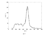
- Figure 7 is a schematic illustration of the energy spectrum of a flashing crystal strip of the edge of the nuclear detector of Figure 5;
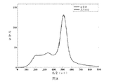
- Figure 8 is a schematic diagram of an average energy spectrum of a scintillation crystal strip of the nuclear detector of Figure 5, wherein the average energy resolution of the scintillation crystal strip is 14.8%;
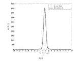
- Figure 9 is a schematic diagram showing the time resolution of the nuclear detector according to Figure 5, wherein the time resolution is 941.4 ps;
- Figure 10 is a front elevational view of a nuclear detector in accordance with another embodiment of the present invention.
- Figure 11 is a front elevational view of a nuclear detector in accordance with yet another embodiment of the present invention.
- FIG. 1 is a front view of a nuclear detector according to a preferred embodiment of the present invention
- FIG. 2 is a perspective view of a light guide according to the nuclear detector of FIG. 1.
- the nuclear detector provided by the present invention
- a scintillation crystal array 10, a light guide 20, and a photodetector array 30 are disposed.
- the light guide 20 is disposed between the scintillation crystal array array 30 and the photodetector array 30 and coupled to the scintillation crystal array array 30 and the photodetector array 30, respectively.
- the scintillation crystal array 10 includes m ⁇ n scintillation crystal strips 11 closely arranged and of the same size, m and n are natural numbers not less than 5, and the individual scintillation crystal strips 11 are hexagonal polished cuboids, single
- the side of the scintillation crystal strip 11 is coated with an opaque diffuse material such as BaSO 4 powder or a specular reflection film, and the bottom surfaces of the individual scintillation crystal strips 11 are combined to form the bottom surface of the scintillation crystal array 10; as shown in FIG. 2, the light guide 20 includes a light guide body 21, a first slit 22 and a second slit 23.
- the light guide body 21 has a rectangular parallelepiped shape.
- the top surface of the light guide 20 is coupled to the bottom surface of the scintillation crystal array 10.
- the top surface area of the light guide 20 is equal to the scintillation crystal array 10.
- the bottom surface area of the light guide 20 is further provided with four first slits 22 and four second slits 23, and the four first slits 22 are respectively parallel to the four sides of the top surface of the light guide 20, and the four second cuts are respectively
- the slits 23 are also parallel to the four sides of the top surface of the light guide 20, respectively, and the first slit 22 and the second slit 23 extend from the top surface of the light guide 20 toward the inside of the light guide 20 along the thickness direction of the light guide 20, four second Slit 23 and four first cuts 22 as compared to closer to the center 20 of the light guide.
- the distance of the first slit 22 from the edge of the light guide 20 is equal to the width of the single scintillation crystal strip 11, and the distance between the first slit 22 and the second slit 23 is equal to the width of the single scintillation crystal strip 11.
- the width, the depth of the first slit 22 is greater than the depth of the second slit 23.
- the top surface of the photodetector array 30 is coupled to the bottom surface of the light guide 20.
- the photodetector array 30 includes x ⁇ y photodetectors 31 arranged in sequence and of the same size, x and y are natural numbers, and the single photodetector 31
- the cross-sectional area is greater than the cross-sectional area of the single scintillation crystal strip 11, and the top surface area of the photodetector array 30 is smaller than the bottom surface area of the light guide 20.
- the scintillation crystal array 10 is formed by 13 ⁇ 13 individual scintillation crystal strips 11, and the material of the scintillation crystal strip 11 is strontium silicate scintillation crystal (LYSO), a single flicker.
- the size of the crystal strip was 1.89 mm ⁇ 1.89 mm ⁇ 13 mm, and the overall size of the scintillation crystal array 10 was 26.5 mm ⁇ 26.5 mm ⁇ 13.3 mm, and BaSO 4 powder was applied between the respective scintillation crystal strips 11.
- the light guide 20 has a thickness of 1.4 mm, the first slit 22 has a width of 0.2 mm, a depth of 1.0 mm, a second slit has a width of 0.2 mm, a depth of 0.4 mm, and the first slit 22 and the second slit 23
- the middle is filled with an opaque material, such as a black opaque paint. It is worth noting that in order to achieve a better light guiding effect, the side of the light guide 20 is also coated with an opaque substance.
- the photodetector array 30 adopts 6 ⁇ 6 silicon photomultiplier tubes 31, and the size of the single silicon photomultiplier tube 31 is 4 mm ⁇ 4 mm ⁇ 0.65 mm, and the gap between the adjacent silicon photomultiplier tubes 31 has a slit width of 0.2. Mm.
- FIG. 3 is a schematic diagram of a multiplexing circuit of the nuclear detector according to FIG. 1.
- the multiplexing circuit of the nuclear detector of the present invention employs an equalized charge distribution circuit, and the circuit includes 16 channels.
- the scintillation pulse signal of the silicon photomultiplier tube 31 of each channel firstly distributes the charge through two resistors 40 to generate an 8-way weighting signal 50, and the resistance of the resistor 40 is 220 ohms; by using the equalization charge distribution circuit, x ⁇ y
- the scintillation pulse signal of the silicon photomultiplier tube 31 of the path is reduced to x+y path, and finally the position spectrum is generated by the Anger algorithm.
- the Anger algorithm is a common technical means in the field and will not be described here.
- FIG. 4 is a schematic diagram of an energy spectrum of a nuclear detector according to an embodiment of the present invention.
- the scintillation pulse signal generated by the silicon photomultiplier tube 31 is further processed by a multiplexing circuit and further digitized by multi-threshold (MVT).
- MVT multi-threshold
- Method processing Different from the traditional fixed-time ADC method for voltage sampling, the MVT digitization method pre-sets multiple voltage thresholds in the system, records the time corresponding to the time when the scintillation pulse signal reaches each voltage threshold, and further a priori knowledge of the scintillation pulse model.
- the time, energy, baseline drift and decay time information of the scintillation pulse signal can be obtained by fitting, and the position information can be further obtained by the energy information.
- FIG. 4 is the position spectrum image of the nuclear detector of FIG. 1 obtained by the MVT digitization method. As can be seen from Fig. 4, the position spectrum of the 13 ⁇ 13 crystals of the nuclear detector is clearly visible.
- FIG. 5 shows an energy spectrum of a 13 ⁇ 13 scintillation crystal strip obtained by the SiPM-based nuclear detector according to FIG. 1 after applying a position look-up table algorithm.
- FIG. 5 shows an energy spectrum of a 13 ⁇ 13 scintillation crystal strip obtained by the SiPM-based nuclear detector according to FIG. 1 after applying a position look-up table algorithm.
- FIG. 5 shows an energy spectrum of a 13 ⁇ 13 scintillation crystal strip obtained by the SiPM-based nuclear detector according to FIG. 1 after applying a position look-up table algorithm.
- FIG. 5 shows an energy spectrum of a 13 ⁇ 13 scintillation crystal strip obtained by the SiPM-based nuclear detector according to FIG. 1 after applying a position look-up table algorithm.
- FIG. 5 shows an energy spectrum of a 13 ⁇ 13 scintillation crystal strip obtained by the SiPM-based nuclear detector according to FIG. 1 after applying a position look-up table algorithm.
- FIG. 5 shows an energy spectrum of a 13 ⁇ 13 scintillation crystal
- the energy resolution of the scintillation crystal strip at the edge of the nuclear detector is worse than the energy resolution of the scintillation crystal strip located at the center of the nuclear detector.
- 8 is a schematic diagram of the average energy spectrum of a scintillation crystal strip of the nuclear detector of FIG. 5. As can be seen from FIG. 8, the average energy resolution of the 13 ⁇ 13 scintillation crystal strips is 14.8%.
- FIG. 9 is a schematic diagram showing the time resolution according to the nuclear detector of FIG. 5.
- a pair of SiPM-based nuclear detectors are placed to extract 4573 pairs of adjacent response lines (abbreviated as LOR, Line of Response).
- LOR Line of Response
- the statistics are consistent with the time distribution spectrum, and all events pass 350-650 keV.
- the energy window was screened and the time resolution obtained by Gaussian fitting was 941.4 ps.
- FIG. 10 is a front elevational view of a nuclear detector in accordance with another embodiment of the present invention.
- both the scintillation crystal array 110 and the photodetector array 130 of the nuclear detector are the same as the embodiment shown in FIG. The same, no longer repeat here.
- the difference is that, in the embodiment of FIG. 10, only four first slits 122 are disposed on the top surface of the light guide 120, and the first slits 122 are respectively cut parallel to the four sides of the top surface of the light guide 120, first The slit 122 extends from the top surface of the light guide 120 toward the inside of the light guide 120 along the thickness direction of the light guide 120.
- the distance between the four first slits 122 from the edge of the corresponding light guide 120 is between 1.1 and 1.9 times the width of the flashing crystal strip.
- the depth of the first slit 122 is between 0.1 and 0.5 times the thickness of the light guide 120.
- the distance of the first slit 122 from the edge of the corresponding light guide 120 is 1.5 times the width of the scintillation crystal strip, the depth of the first slit 122 is 0.4 mm, and the thickness of the light guide 120 is 1.4. Mm.
- FIG. 11 is a front elevational view of a nuclear detector in accordance with yet another embodiment of the present invention.
- both the scintillation crystal array 210 and the photodetector array 230 of the nuclear detector are the same as the embodiment shown in FIG. The same, no longer repeat here.
- the difference is that, in the embodiment of FIG. 11 , the light guide 220 has a tapered shape, including an opposite top surface, a bottom surface and four sides.
- the top surface area of the light guide 220 is larger than the bottom surface area, and the bottom surface area of the light guide 220 is equal to the photoelectric detection.
- the first slit 222 has a width of 0.2 mm and a depth of 1.0 mm
- the second slit 223 has a width of 0.2 mm and a depth of 0.4 mm.
- the material used for the light guide is a transparent element such as ordinary inorganic glass, plexiglass or scintillation crystal.
- the number of layers of the light guide is between 2-4 layers, and all the light guides are tired.
- the thickness is between 0.1mm and 40mm.
- the light guide may also be in the shape of a truncated cone, a cylinder or a cone-like polyhedron, the width or diameter of the light guide being between the width of the scintillation crystal array and the width of the photodetector array.
- the opaque substance filled in the first slit or the second slit of the light guide may also be a specular reflection film (ESR, Enhanced Specular Reflector).
- ESR specular reflection film
- the number of slits of the light guide may also be greater than 2, and the number of slits of the light guide may not exceed 40.
- the scintillation crystal strip is an inorganic scintillation crystal, including bismuth ruthenate, strontium silicate, strontium bromide, strontium silicate, strontium silicate, cesium fluoride, sodium iodide, cesium iodide, and the like.
- the width of a single scintillation crystal strip in the scintillation crystal array is between 0.5 mm and 4 mm.
- the photodetector in the photodetector array may also employ an avalanche photodiode (APD), a multi-pixel photon counter (MPPC), and a Geiger mode avalanche photodiode (G-APD).
- APD avalanche photodiode
- MPPC multi-pixel photon counter
- G-APD Geiger mode avalanche photodiode
- the nuclear detector provided by the invention has a size in which the size of the scintillation crystal strip is significantly smaller than that of the photodetector in the scintillation crystal array, that is, the direct coupling of the scintillation crystal strip and the photodetector 1:1 cannot be realized, in both cases A light guide with slits is added between them to enable a high spatial resolution nuclear detector. Due to the small thickness of the light guide, the scintillation photon loss per scintillation crystal is small, and the signal-to-noise ratio of the scintillation photon is hardly lost, which not only achieves high spatial resolution of the nuclear detector, but also does not deteriorate the performance of the nuclear detector. The energy resolution and time resolution of the nuclear detection satisfy the needs of the high spatial resolution PET detector, and the production is convenient and the manufacturing is convenient.
Landscapes
- Physics & Mathematics (AREA)
- Health & Medical Sciences (AREA)
- Spectroscopy & Molecular Physics (AREA)
- Life Sciences & Earth Sciences (AREA)
- General Physics & Mathematics (AREA)
- High Energy & Nuclear Physics (AREA)
- Molecular Biology (AREA)
- Crystallography & Structural Chemistry (AREA)
- Chemical & Material Sciences (AREA)
- Engineering & Computer Science (AREA)
- Biomedical Technology (AREA)
- General Health & Medical Sciences (AREA)
- Medical Informatics (AREA)
- Nuclear Medicine, Radiotherapy & Molecular Imaging (AREA)
- Optics & Photonics (AREA)
- Measurement Of Radiation (AREA)
- Nuclear Medicine (AREA)
Abstract
一种核探测器包括闪烁晶体阵列(10)、光导(20)和光电探测器阵列(30),闪烁晶体阵列(10)包括若干个依序紧密排列且尺寸相同的闪烁晶体条(11),光电探测器阵列(30)包括若干个依序排列的光电探测器,光电探测器的横截面积大于闪烁晶体条(11)的横截面积,光导(20)包括相对的顶面、底面和侧面,光导(20)的顶面与闪烁晶体阵列(10)耦合,光导(20)的底面与光电探测器阵列(30)耦合,光导(20)的厚度介于0.1mm-40mm之间;光导(20)还具有设置于靠近所述光导(20)的边缘处的切缝(22, 23),切缝(22, 23)自光导(20)的顶面向底面延伸,切缝(22, 23)的深度介于光导(22, 23)的厚度的0.1-0.5倍之间。
Description
本发明涉及一种辐射探测设备,更具体地涉及一种核探测器。
在γ照相机、正电子发射计算机断层成像(简称PET,Positron Emission Tomography)系统、辐射探测仪和晶体性能检测装置等核探测设备中,核探测器的空间分辨率是体现核探测设备性能的一个重要指标。比如在PET系统中,空间分辨率体现了PET系统对细微组织的空间辨识能力,是PET系统中最为重要的两个指标之一,也同时是评价PET图像质量的重要指标之一。PET系统作为一种影像系统最根本的评价标准是重建图像的质量,高质量的重建图像要求有良好的分辨率,空间分辨率是过去十多年来PET系统开发中一直重点优化的对象。特别是在动物PET系统中,由于动物大小的原因,对系统成像空间分辨率的要求远高于临床PET系统。
现有技术中通常将晶体条切细至小于2.0mm的核探测器称为高空间分辨率核探测器,目前的高空间分辨率核探测器通常采用以下几种设计方案:
第一种,通过位置敏感型光电倍增管(简称PSPMT)耦合闪烁晶体阵列的方式实现高空间分辨率,位置敏感型光电倍增管具有增益高(106)、噪声低的特点,能够实现非常高的空间分辨率,已经有团队通过该耦合方式实现了空间分辨率要求很高的小动物PET系统(参考文献Luyao Wang,Jun Zhu,
Xiao Liang,Ming Niu,Xiaoke Wu,Chien-Min Kao,Heejong Kim and Qingguo Xie,“Performance evaluation of the LH system-A large FOV small-animal PET system”,Physics in Medicine and Biology[J],2014),达到了较好的系统性能。
第二种,通过雪崩光电二极管阵列(简称APD array)与相同尺寸的闪烁晶体阵列直接耦合的方式实现高空间分辨率,位置敏感型雪崩光电二极管体积小巧,正常工作时需求的电压不高,搭建PET探测器具有较强的灵活性,也可降低一部分系统集成工程难度,已有团队通过该耦合方式实现了较高空间分辨率的小动物PET探测器(参考文献Bergeron M,Cadorette J,Beaudoin J F,et al.Performance Evaluation of the LabPET APD-Based Digital PET Scanner[J].IEEE Transactions on Nuclear Science,2009,56(1):10-16)。
第三种,通过硅光电倍增管阵列(简称SiPM array)与相同尺寸的闪烁晶体阵列1:1直接耦合的方式来搭建PET探测器。硅光电倍增管增益为106,与光电倍增管媲美,噪声低,体积小巧,排列紧实,时间性能良好。使用SiPM array搭建PET探测器时,前端探测器输出信号的信噪比高,探测器灵活性强,也可降低系统集成的工程难度。由于是半导体器件,具有大量生产时价格低廉的优势,尤其适合在PET这种探测器数量众多的仪器设备中。已有团队通过SiPM阵列和闪烁晶体阵列1:1直接耦合的方式实现了PET探测器的设计、生产,并且完成了系统集成,得到了2.5mm左右的PET系统空间分辨率(参考文献Daoming Xi,Jingjing Liu,Yanzhao Li,Jun Zhu,Ming Niu,Peng Xiao,Qingguo Xie,"Investigation of continuous scintillator/SiPM detector for local extremely high spatial resolution PET",in Conference Record of the2011IEEE Nuclear Science Symposium and Medical Imaging Conference[C],pp.4429-4432,2011)
然而,上述的核探测器设计中还存在诸多不足之处,比如第一种基于PSPMT耦合阵列闪烁晶体的核探测器,首先,其光电倍增管十分昂贵,对于通道数成千上万的PET系统而言,使用的探测器数量相当多,设备成本太高;其次,光电倍增管本身体积较大,不利于灵活的搭建系统;再次,光电倍增管运行时一般需要一千伏左右的高压,这会增加PET系统集成时的工程难度。对于第二种通过APD阵列耦合阵列闪烁晶体的核探测器,由于雪崩光电二极管有着天然的缺陷,增益不够高,噪声也较大,会造成前端探测器产生的电脉冲信号的信噪比将低,影响电子学读出效果,最终降低PET探测器的性能。对于第三种通过硅光电倍增管阵列和相同尺寸的阵列闪烁晶体1:1直接耦合的方式组成的PET探测器,虽然其能够获得较好的能量分辨率和时间分辨率,但是在该耦合方式下其空间分辨率受限于硅光电倍增管的尺寸,难以通过切细阵列晶体中晶体条的尺寸进一步提高PET探测器的空间分辨率。
综上所述,现有技术中基于PSPMT耦合阵列闪烁晶体的核探测器不仅成本太高,而且系统集成灵活度不高和工程难度较大,虽然在高空间分辨率的PET系统中可以采用,但付出的研发成本和生产成本都比较高。基于APD阵列耦合闪烁晶体阵列的核探测器,其雪崩光电二极管增益较低,信号的信噪比不好,会降低高空分辨率PET系统的性能。基于SiPM阵列1:1直接耦合闪烁晶体的PET探测器兼有上述两种方式的优点,但是受限于SiPM阵列中单颗SiPM的尺寸,难以获得晶体条切细至2mm以下的高空间分辨率核探测器。
因此,针对上述技术问题,有必要提出一种成本低廉、系统集成灵活度高且空间分辨率更高的核探测器以克服上述缺陷。
发明内容
本发明的目的是提供一种核探测器,从而解决现有技术中核探测器的成本高、系统集成灵活度低且空间分辨率不高的问题。
为了解决上述技术问题,本发明的技术方案是提供一种核探测器,所述核探测器包括闪烁晶体阵列、光导和光电探测器阵列,所述闪烁晶体阵列包括若干个依序紧密排列且尺寸相同的闪烁晶体条,所述光电探测器阵列包括若干个依序排列的光电探测器,所述光电探测器的横截面积大于所述闪烁晶体条的横截面积,所述光导包括相对的顶面、底面和侧面,所述光导的顶面与所述闪烁晶体阵列耦合,所述光导的底面与所述光电探测器阵列耦合,所述光导的厚度介于0.1mm-40mm之间;所述光导还具有切缝,所述切缝设置于靠近所述光导的边缘处,所述切缝自所述光导的顶面向所述光导的底面延伸,所述切缝的深度介于所述光导的厚度的0.1-0.5倍之间。
根据本发明的一个实施例,所述光导呈长方体形状,所述切缝的延伸方向垂直于所述光导的所述顶面和所述底面。
根据本发明的一个实施例,所述切缝距离所述光导的所述侧面的距离介于所述闪烁晶体条的宽度的1.1-1.9倍之间。
根据本发明的一个实施例,所述光导呈锥形台形状,所述光导的顶面面积大于所述光导的底面面积,所述切缝的延伸方向平行于所述锥形台的侧面。
根据本发明的一个实施例,所述切缝包括第一切缝和第二切缝,所述第一切缝距离所述光导的所述侧面的距离等于所述闪烁晶体条的宽度,所述第二切缝距离所述光导的所述侧面的距离等于所述闪烁晶体条的宽度的两倍,
所述第一切缝的深度大于所述第二切缝的深度。
根据本发明的一个实施例,所述切缝的数量介于1-40之间,所述切缝自所述光导的侧面向所述光导的中心依次分布,所述切缝的深度自所述光导的侧面处向所述光导的中心依次递减。
根据本发明的一个实施例,所述闪烁晶体条的宽度介于0.5mm-4mm之间。
根据本发明的一个实施例,所述闪烁晶体条的侧面涂覆有不透光物质。
根据本发明的一个实施例,所述不透光物质为硫酸钡粉末或者镜面反射膜。
根据本发明的一个实施例,所述切缝中和所述光导的侧面涂覆有不透光物质。
根据本发明的一个实施例,所述不透光物质为黑色油漆。
根据本发明的一个实施例,所述光导的层数介于1-4层之间,各层所述光导的累计厚度介于0.1mm-40mm之间。
本发明提供的核探测器,在闪烁晶体阵列中闪烁晶体条的尺寸明显小于光电探测器尺寸时,也就是无法实现闪烁晶体条和光电探测器1:1直接耦合的情况下,在两者之间加入具有切缝的光导,从而能够实现高空间分辨率的核探测器。由于光导的厚度较小,对闪烁晶体每次的闪烁光子损失较小,几乎不损失闪烁光子的信噪比,不仅能够实现核探测器的高空间分辨率,而且不会恶化核探测器的性能,使得该核探测的能量分辨率、符合时间分辨率均满足高空间分辨率PET探测器的需要,并且生产方便,制造便捷,成本低廉。
图1是根据本发明的一个优选实施例的核探测器的正面示意图;
图2是根据图1的核探测器的光导的立体示意图;
图3是根据图1的核探测器的复用电路的示意图;
图4是根据图1的核探测器的晶体位置谱的示意图;
图5是根据图1的核探测器的能量谱的示意图;
图6是根据图5的核探测器的中心闪烁晶体条的能量谱的示意图;
图7是根据图5的核探测器的边缘闪烁晶体条的能量谱的示意图;
图8是根据图5的核探测器的闪烁晶体条的平均能量谱的示意图,其中闪烁晶体条的平均能量分辨率为14.8%;
图9是根据图5的核探测器的符合时间分辨率的示意图,其中符合时间分辨率为941.4ps;
图10是根据本发明的另一个实施例的核探测器的正面示意图;
图11是根据本发明的又一个实施例的核探测器的正面示意图。
以下结合具体实施例,对本发明做进一步说明。应理解,以下实施例仅用于说明本发明而非用于限制本发明的范围。
图1为根据本发明的一个优选实施例的核探测器的正面示意图,图2为根据图1的核探测器的光导的立体示意图,由图1结合图2可知,本发明提供的核探测器包括闪烁晶体阵列10、光导20以及光电探测器阵列30,光导20设置于闪烁晶体阵列阵列30和光电探测器阵列30之间且分别与闪烁晶体阵列阵列30和光电探测器阵列30耦合。具体地,闪烁晶体阵列10包括m×n个依序紧密排列且尺寸相同的闪烁晶体条11,m、n均为不小于5的自然数,单个的闪烁晶体条11为六面抛光的长方体,单个的闪烁晶体条11的侧面涂抹不透光的漫反射物质,比如BaSO4粉末或者镜面反射膜,单个的闪烁晶体条11的底面组合形成了闪烁晶体阵列10的底面;如图2所示,光导20包
括光导本体21、第一切缝22和第二切缝23,光导本体21呈长方体形状,光导20的顶面与闪烁晶体阵列10的底面耦合,光导20的顶面面积等于闪烁晶体阵列10的底面面积,光导20的顶面上还设置有四条第一切缝22和四条向第二切缝23,四条第一切缝22分别平行于光导20的顶面的四条边,四条第二切缝23也分别平行于光导20的顶面的四条边,第一切缝22和向第二切缝23均自光导20的顶面沿着光导20的厚度方向向光导20内部延伸,四条第二切缝23与四条第一切缝22相比更靠近光导20的中心。在图1的实施例中,第一切缝22距离光导20边缘的距离等于单个闪烁晶体条11的宽度,第一切缝22和第二切缝23之间的距离等于单个闪烁晶体条11的宽度,第一切缝22的深度大于第二切缝23的深度。光电探测器阵列30的顶面与光导20的底面耦合,光电探测器阵列30包括x×y个依序排列且尺寸相同的光电探测器31,x、y均为自然数,单个光电探测器31的横截面积大于单个闪烁晶体条11的横截面积,光电探测器阵列30的顶面面积小于光导20的底面面积。
更具体地,在图1的实施例中,闪烁晶体阵列10由13×13个单独的闪烁晶体条11形成,闪烁晶体条11的材质为硅酸钇镥闪烁晶体(简称LYSO),单根闪烁晶体条的尺寸为1.89mm×1.89mm×13mm,闪烁晶体阵列10的整体尺寸为26.5mm×26.5mm×13.3mm,各个闪烁晶体条11之间涂抹BaSO4粉末。光导20的厚度为1.4mm,第一切缝22的宽度为0.2mm,深度为1.0mm,第二切缝的宽度为0.2mm,深度为0.4mm,第一切缝22和第二切缝23中均填充不透光物质,比如黑色不透光的油漆。值得注意的是,为了实现更好的导光效果,光导20的侧面也涂抹了不透光物质。光电探测器阵列30采用6×6个硅光电倍增管31,单个硅光电倍增管31的尺寸为4mm×4mm×0.65mm,相邻的硅光电倍增管31之间具有缝隙,缝隙的宽度为0.2mm。
图3为根据图1的核探测器的复用电路的示意图,由图3可知,本发明的核探测器的复用电路采用了均衡电荷分配电路,该电路包括16个通道,
每个通道的硅光电倍增管31的闪烁脉冲信号先经过两个电阻40均衡分配电荷以产生8路加权信号50,电阻40的阻值为220欧姆;通过该均衡电荷分配电路可使x×y路的硅光电倍增管31的闪烁脉冲信号减少为x+y路,最后通过Anger算法产生位置谱。值得注意的是,Anger算法为本领域的常用技术手段,在此不再赘述。
图4是根据本发明的一个实施例的核探测器的能量谱的示意图,由图4可知,硅光电倍增管31产生的闪烁脉冲信号经过复用电路处理后,进一步采用多阈值(MVT)数字化方法处理。不同于传统的固定时间进行电压采样的ADC方法,MVT数字化方法预先在系统中设置多个电压阈值,记录闪烁脉冲信号到达各个电压阈值时对应的时间,进一步借助于闪烁脉冲模型的先验知识,通过拟合即可得到闪烁脉冲信号的时间、能量、基线漂移和衰减时间信息,进一步通过能量信息可获得位置信息,图4即为通过MVT数字化方法获得的图1的核探测器的位置谱图像,由图4可见,该核探测器的13×13个晶体的位置谱清晰可见。
图5示出了根据图1的基于SiPM的核探测器在应用了位置查表算法后获得的13×13个闪烁晶体条的能量谱,从图5中可知,通过对能量谱中光电峰进行高斯拟合可得每个闪烁晶体条上的能量分辨率,单个闪烁晶体条的能量分辨率介于12.9%-30.1%之间。图6是根据图5的核探测器的中心闪烁晶体条的能量谱的示意图,图7是根据图5的核探测器的边缘闪烁晶体条的能量谱的示意图,由图6对比图7可知,位于核探测器边缘的闪烁晶体条的能量分辨率与位于核探测器中心的闪烁晶体条的能量分辨率相比更差。图8为根据图5的核探测器的闪烁晶体条的平均能量谱的示意图,由图8可知,13×13个闪烁晶体条的平均能量分辨率为14.8%。
图9是根据图5的核探测器的符合时间分辨率的示意图,由图9可知,对正对放置的基于SiPM的核探测器抽取4573对相邻的响应线(简称LOR,Line of Response)统计符合时间分布谱,所有的事件均经过350-650keV的
能量窗筛选,通过高斯拟合后获得的符合时间分辨率为941.4ps。
图10为根据本发明的另一个实施例的核探测器的正面示意图,在图10的实施例中,核探测器的闪烁晶体阵列110和光电探测器阵列130均与图1所示的实施例相同,在此不再赘述。不同之处为,图10的实施例中,光导120的顶面上仅设置有四条第一切缝122,该第一切缝122的分别平行于光导120的顶面的四条边切割,第一切缝122自光导120的顶面沿着光导120的厚度方向向光导120内部延伸,四条第一切缝122距离相应的光导120的边缘的距离介于闪烁晶体条宽度的1.1-1.9倍之间,第一切缝122的深度介于光导120的厚度的0.1-0.5倍之间。比如,在图10的实施例中,第一切缝122距离相应的光导120的边缘的距离为闪烁晶体条的宽度的1.5倍,第一切缝122的深度为0.4mm,光导120厚度为1.4mm。
图11是根据本发明的又一个实施例的核探测器的正面示意图,在图11的实施例中,核探测器的闪烁晶体阵列210和光电探测器阵列230均与图1所示的实施例相同,在此不再赘述。不同之处为,图11的实施例中,光导220呈锥形台状,包括相对的顶面、底面和四个侧面,光导220的顶面面积大于底面面积,光导220的底面面积等于光电探测器阵列230的顶面面积;光导220的顶面上设置有四条第一切缝222和四条第二切缝223,第一切缝222和第二切缝223所在的平面的分别平行于光导220的四个侧面,四条第一切缝222距离相应的光导220的侧面的距离等于单个闪烁晶体条的宽度,第二切缝223距离相应的光导220的侧面的距离等于单个闪烁晶体条的宽度的两倍;第一切缝222的深度大于第二切缝223的深度。比如,在图10的实施例中,第一切缝222的宽度为0.2mm,深度为1.0mm,第二切缝223的宽度为0.2mm,深度为0.4mm。
根据本发明的一个实施例,光导采用的材料为普通无机玻璃、有机玻璃或者闪烁晶体等透明元件。
根据本发明的一个实施例,光导的层数介于2-4层之间,所有光导的累
计厚度介于0.1mm-40mm之间。
根据本发明的一个实施例,光导还可为圆锥台、圆柱体或者类锥形多面体等形状,光导的宽度或者直径介于闪烁晶体阵列的宽度和光电探测器阵列的宽度之间。
根据本发明的一个实施例,光导的第一切缝或者第二切缝中填充的不透光物质还可以为镜面反射膜(简称ESR,Enhanced Specular Reflector)。
根据本发明的另一个实施例,光导的切缝数量还可大于2,光导的切缝数量不超过40个。
根据本发明的一个实施例,闪烁晶体条为无机闪烁晶体,包括锗酸铋、硅酸镥、溴化镧、硅酸钇镥、硅酸镥、氟化钡、碘化钠和碘化铯等。
根据本发明另外的实施例,闪烁晶体阵列中的单个闪烁晶体条的宽度介于0.5mm-4mm之间。
根据本发明的一个实施例,光电探测器阵列中的光电探测器还可采用雪崩光电二极管(APD)、多像素光子计数器(MPPC)和盖革模式雪崩光电二极管(G-APD)。
本发明提供的核探测器,在闪烁晶体阵列中闪烁晶体条的尺寸明显小于光电探测器尺寸时,也就是无法实现闪烁晶体条和光电探测器1:1直接耦合的情况下,在两者之间加入具有切缝的光导,从而能够实现高空间分辨率的核探测器。由于光导的厚度较小,对闪烁晶体每次的闪烁光子损失较小,几乎不损失闪烁光子的信噪比,不仅能够实现核探测器的高空间分辨率,而且不会恶化核探测器的性能,使得该核探测的能量分辨率、符合时间分辨率均满足高空间分辨率PET探测器的需要,并且生产方便,制造便捷。
以上所述的,仅为本发明的较佳实施例,并非用以限定本发明的范围,本发明的上述实施例还可以做出各种变化。即凡是依据本发明申请的权利要求书及说明书内容所作的简单、等效变化与修饰,皆落入本发明专利的权利
要求保护范围。本发明未详尽描述的均为常规技术内容。
Claims (12)
- 一种核探测器,所述核探测器包括闪烁晶体阵列、光导和光电探测器阵列,所述闪烁晶体阵列包括若干个依序紧密排列且尺寸相同的闪烁晶体条,所述光电探测器阵列包括若干个依序排列的光电探测器,所述光电探测器的横截面积大于所述闪烁晶体条的横截面积,所述光导包括相对的顶面、底面和侧面,所述光导的顶面与所述闪烁晶体阵列耦合,所述光导的底面与所述光电探测器阵列耦合,其特征在于,所述光导的厚度介于0.1mm-40mm之间;所述光导还具有切缝,所述切缝设置于靠近所述光导的边缘处,所述切缝自所述光导的顶面向所述光导的底面延伸,所述切缝的深度介于所述光导的厚度的0.1-0.5倍之间。
- 根据权利要求1所述的核探测器,其特征在于,所述光导呈长方体形状,所述切缝的延伸方向垂直于所述光导的所述顶面和所述底面。
- 根据权利要求2所述的核探测器,其特征在于,所述切缝距离所述光导的所述侧面的距离介于所述闪烁晶体条的宽度的1.1-1.9倍之间。
- 根据权利要求1所述的核探测器,其特征在于,所述光导呈锥形台形状,所述光导的顶面面积大于所述光导的底面面积,所述切缝的延伸方向平行于所述锥形台的侧面。
- 根据权利要求2或4所述的核探测器,其特征在于,所述切缝包括第一切缝和第二切缝,所述第一切缝距离所述光导的所述侧面的距离等于所述闪烁晶体条的宽度,所述第二切缝距离所述光导的所述侧面的距离等于所述 闪烁晶体条的宽度的两倍,所述第一切缝的深度大于所述第二切缝的深度。
- 根据权利要求1所述的核探测器,其特征在于,所述切缝的数量介于1-40之间,所述切缝自所述光导的侧面向所述光导的中心依次分布,所述切缝的深度自所述光导的侧面处向所述光导的中心依次递减。
- 根据权利要求1所述的核探测器,其特征在于,所述闪烁晶体条的宽度介于0.5mm-4mm之间。
- 根据权利要求1所述的核探测器,其特征在于,所述闪烁晶体条的侧面涂覆有不透光物质。
- 根据权利要求8所述的核探测器,其特征在于,所述不透光物质为硫酸钡粉末或者镜面反射膜。
- 根据权利要求1所述的核探测器,其特征在于,所述切缝中以及所述光导的侧面涂覆有不透光物质。
- 根据权利要求10所述的核探测器,其特征在于,所述不透光物质为黑色油漆。
- 根据权利要求1所述的核探测器,其特征在于,所述光导的层数介于1-4层之间,各层所述光导的累计厚度介于0.1mm-40mm之间。
Priority Applications (4)
| Application Number | Priority Date | Filing Date | Title |
|---|---|---|---|
| FIEP17919078.0T FI3637148T3 (fi) | 2017-07-28 | 2017-10-27 | Ydinilmaisin |
| EP17919078.0A EP3637148B1 (en) | 2017-07-28 | 2017-10-27 | Nucleus detector |
| US16/623,038 US11194062B2 (en) | 2017-07-28 | 2017-10-27 | Nuclear detector |
| JP2019568355A JP7224649B2 (ja) | 2017-07-28 | 2017-10-27 | 核検出器 |
Applications Claiming Priority (2)
| Application Number | Priority Date | Filing Date | Title |
|---|---|---|---|
| CN201710631228.4 | 2017-07-28 | ||
| CN201710631228.4A CN107167832A (zh) | 2017-07-28 | 2017-07-28 | 一种核探测器 |
Publications (1)
| Publication Number | Publication Date |
|---|---|
| WO2019019449A1 true WO2019019449A1 (zh) | 2019-01-31 |
Family
ID=59817568
Family Applications (1)
| Application Number | Title | Priority Date | Filing Date |
|---|---|---|---|
| PCT/CN2017/108097 Ceased WO2019019449A1 (zh) | 2017-07-28 | 2017-10-27 | 一种核探测器 |
Country Status (6)
| Country | Link |
|---|---|
| US (1) | US11194062B2 (zh) |
| EP (1) | EP3637148B1 (zh) |
| JP (1) | JP7224649B2 (zh) |
| CN (1) | CN107167832A (zh) |
| FI (1) | FI3637148T3 (zh) |
| WO (1) | WO2019019449A1 (zh) |
Families Citing this family (12)
| Publication number | Priority date | Publication date | Assignee | Title |
|---|---|---|---|---|
| CN107167832A (zh) * | 2017-07-28 | 2017-09-15 | 苏州瑞派宁科技有限公司 | 一种核探测器 |
| CN107728188B (zh) * | 2017-10-09 | 2019-08-16 | 山东麦德盈华科技有限公司 | 一种用于射线位置和能量测量的探测器和信号读出方法 |
| CN109765603A (zh) * | 2017-11-09 | 2019-05-17 | 苏州瑞派宁科技有限公司 | 一种光导及核探测器 |
| CN109856664B (zh) * | 2018-12-04 | 2020-12-01 | 山东麦德盈华科技有限公司 | 一种部分光导不切割的pet探测器 |
| CN109856665B (zh) | 2018-12-04 | 2020-12-01 | 山东麦德盈华科技有限公司 | 一种减少硅光电倍增管用量的pet探测器及探测方法 |
| CN109765599B (zh) * | 2018-12-11 | 2022-11-01 | 东软医疗系统股份有限公司 | 基于硅光电倍增管的探测器、机架和pet设备 |
| CN112641455B (zh) * | 2019-10-09 | 2024-06-18 | 安徽麦德盈华影像技术有限公司 | 一种头部渐窄型全身pet装置 |
| CN110764182B (zh) * | 2019-11-08 | 2021-03-02 | 江苏赛诺格兰医疗科技有限公司 | 一种用于闪烁体探测器的光导制作方法 |
| CN115153600B (zh) * | 2021-06-28 | 2026-04-21 | 湾影科技(深圳)有限公司 | 检测模块和具有该检测模块的发射成像设备 |
| CN114486950A (zh) * | 2022-01-14 | 2022-05-13 | 中国原子能科学研究院 | 射线成像方法和装置 |
| CN115220084B (zh) * | 2022-03-25 | 2024-12-24 | 北京滨松光子技术股份有限公司 | 一种闪烁晶体阵列、探测器、医疗影像设备及制作方法 |
| CN119509719A (zh) * | 2024-11-13 | 2025-02-25 | 上海理工大学 | 光子数可分辨探测系统及方法 |
Citations (7)
| Publication number | Priority date | Publication date | Assignee | Title |
|---|---|---|---|---|
| JP2004361303A (ja) * | 2003-06-06 | 2004-12-24 | Shimadzu Corp | 放射線検出器 |
| CN1673773A (zh) * | 2004-03-26 | 2005-09-28 | 株式会社岛津制作所 | 辐射检测器及其制造方法 |
| US20060261279A1 (en) * | 2002-11-09 | 2006-11-23 | Crosetto Dario B | Method and apparatus for improving pet detectors |
| CN102879798A (zh) * | 2012-10-18 | 2013-01-16 | 中国科学院高能物理研究所 | 用于射线成像装置的闪烁探测器 |
| CN104049270A (zh) * | 2013-11-22 | 2014-09-17 | 沈阳东软医疗系统有限公司 | 一种光导及其制备方法、辐射探测器 |
| CN105372693A (zh) * | 2015-11-26 | 2016-03-02 | 沈阳东软医疗系统有限公司 | 一种晶体和光导的合成方法及模具 |
| CN107167832A (zh) * | 2017-07-28 | 2017-09-15 | 苏州瑞派宁科技有限公司 | 一种核探测器 |
Family Cites Families (11)
| Publication number | Priority date | Publication date | Assignee | Title |
|---|---|---|---|---|
| JPH0750596B2 (ja) * | 1988-12-05 | 1995-05-31 | 松下電器産業株式会社 | シンチレータ及びその光遮蔽膜の製造方法 |
| EP0958508B1 (en) * | 1997-02-10 | 2007-03-28 | THE UNIVERSITY OF ALBERTA, SIMON FRASER UNIVERSITY, THE UNIV. OF VICTORIA,THE UNIV. OF BRITISH COLUMBIA, carrying on as TRIUMF | Segmented scintillation detector for photon interaction coordinates |
| JP4110994B2 (ja) * | 2003-02-10 | 2008-07-02 | 株式会社島津製作所 | 放射線検出器 |
| JP2004354343A (ja) | 2003-05-30 | 2004-12-16 | Shimadzu Corp | 放射線検出器 |
| JP4525123B2 (ja) * | 2003-06-30 | 2010-08-18 | 株式会社島津製作所 | 放射線検出器およびその製造方法 |
| US7138638B2 (en) | 2003-11-20 | 2006-11-21 | Juni Jack E | Edge effects treatment for crystals |
| US7573035B2 (en) | 2004-10-29 | 2009-08-11 | Koninklijke Philips Electronics N.V. | GOS ceramic scintillating fiber optics x-ray imaging plate for use in medical DF and RF imaging and in CT |
| US20130009066A1 (en) * | 2011-07-06 | 2013-01-10 | Siemens Aktiengesellschaft | Block Detector With Variable Microcell Size For Optimal Light Collection |
| EP2751597B1 (en) * | 2011-10-12 | 2019-09-11 | Koninklijke Philips N.V. | Modelling of tof-doi detector arrays |
| CN104237924B (zh) | 2014-08-20 | 2017-07-28 | 许剑锋 | 网格模具、包括该网格模具的检测器和发射成像设备 |
| CN105655435B (zh) * | 2014-11-14 | 2018-08-07 | 苏州瑞派宁科技有限公司 | 光电转换器、探测器及扫描设备 |
-
2017
- 2017-07-28 CN CN201710631228.4A patent/CN107167832A/zh active Pending
- 2017-10-27 WO PCT/CN2017/108097 patent/WO2019019449A1/zh not_active Ceased
- 2017-10-27 FI FIEP17919078.0T patent/FI3637148T3/fi active
- 2017-10-27 US US16/623,038 patent/US11194062B2/en active Active
- 2017-10-27 JP JP2019568355A patent/JP7224649B2/ja active Active
- 2017-10-27 EP EP17919078.0A patent/EP3637148B1/en active Active
Patent Citations (7)
| Publication number | Priority date | Publication date | Assignee | Title |
|---|---|---|---|---|
| US20060261279A1 (en) * | 2002-11-09 | 2006-11-23 | Crosetto Dario B | Method and apparatus for improving pet detectors |
| JP2004361303A (ja) * | 2003-06-06 | 2004-12-24 | Shimadzu Corp | 放射線検出器 |
| CN1673773A (zh) * | 2004-03-26 | 2005-09-28 | 株式会社岛津制作所 | 辐射检测器及其制造方法 |
| CN102879798A (zh) * | 2012-10-18 | 2013-01-16 | 中国科学院高能物理研究所 | 用于射线成像装置的闪烁探测器 |
| CN104049270A (zh) * | 2013-11-22 | 2014-09-17 | 沈阳东软医疗系统有限公司 | 一种光导及其制备方法、辐射探测器 |
| CN105372693A (zh) * | 2015-11-26 | 2016-03-02 | 沈阳东软医疗系统有限公司 | 一种晶体和光导的合成方法及模具 |
| CN107167832A (zh) * | 2017-07-28 | 2017-09-15 | 苏州瑞派宁科技有限公司 | 一种核探测器 |
Non-Patent Citations (4)
| Title |
|---|
| BERGERON MCADORETTE JBEAUDOIN JF ET AL.: "Performance Evaluation of the LabPET APD-Based Digital PET Scanner [J", IEEE TRANSACTIONS ON NUCLEAR SCIENCE, vol. 56, no. 1, 2009, pages 10 - 16, XP011251277 |
| DAOMING XIJINGJING LIUYANZHAO LIJUN ZHUMING NIUPENG XIAOQINGGUO XIE: "Investigation of continuous scintillator / SiPM detector for local extremely high spatial resolution PET", CONFERENCE RECORD OF THE 2011 IEEE NUCLEAR SCIENCE SYMPOSIUM AND MEDICAL IMAGING CONFERENCE [C, 2011, pages 4429 - 4432, XP032121463, DOI: 10.1109/NSSMIC.2011.6153853 |
| LUYAO WANGJUN ZHUXIAO LIANGMING NIUXIAOKE WUCHIEN-MIN KAOHEEJONG KIMQINGGUO XIE: "Performance evaluation of the Trans-PET9 BioCaliburn® LH system-A large FOV small-animal PET system", PHYSICS IN MEDICINE AND BIOLOGY, 2014 |
| See also references of EP3637148A4 |
Also Published As
| Publication number | Publication date |
|---|---|
| CN107167832A (zh) | 2017-09-15 |
| EP3637148B1 (en) | 2025-02-19 |
| EP3637148A1 (en) | 2020-04-15 |
| US11194062B2 (en) | 2021-12-07 |
| EP3637148A4 (en) | 2021-03-17 |
| FI3637148T3 (fi) | 2025-03-24 |
| JP7224649B2 (ja) | 2023-02-20 |
| US20200309969A1 (en) | 2020-10-01 |
| JP2020528137A (ja) | 2020-09-17 |
Similar Documents
| Publication | Publication Date | Title |
|---|---|---|
| WO2019019449A1 (zh) | 一种核探测器 | |
| US5773829A (en) | Radiation imaging detector | |
| US10203419B2 (en) | Detector component for an X-ray or gamma ray detector | |
| USRE49174E1 (en) | Photosensors arranged on a surface of a scintillator | |
| Derenzo et al. | The Donner 280-crystal high resolution positron tomograph | |
| WO2000028351A1 (en) | Gamma-ray detector employing scintillators coupled to semiconductor drift photodetectors | |
| RU2401440C2 (ru) | Высокоразрешающий детектор для медицинской визуализации | |
| Beekman et al. | Photon-counting versus an integrating CCD-based gamma camera: important consequences for spatial resolution | |
| Del Guerra et al. | An integrated PET-SPECT small animal imager: preliminary results | |
| WO2022037473A1 (zh) | 探测准直单元、探测装置及spect成像系统 | |
| JP2020091274A (ja) | 放射線検出器 | |
| CN209400708U (zh) | 复合探测装置和系统 | |
| US10976450B2 (en) | Combined scintillation crystal, combined scintillation detector and radiation detection device | |
| KR102063828B1 (ko) | 방사선 영상 기기의 신호 검출 방법 및 그 방사선 영상 기기 | |
| CN207020321U (zh) | 一种核探测器 | |
| Burnham et al. | Cylindrical PET detector design | |
| Jiang et al. | A prototype of SiPM-based scintillator Compton camera with capacitive multiplexing readout | |
| CN109407139B (zh) | 组合闪烁晶体及包括组合闪烁晶体的辐射探测装置和系统 | |
| CN207557495U (zh) | 一种光导及核探测器 | |
| Min et al. | Development of a multipurpose gamma-ray imaging detector module with enhanced expandability | |
| Levin et al. | Investigation of a new readout scheme for high resolution scintillation crystal arrays using photodiodes | |
| Alharbi et al. | Retrofitting an environmental monitor with a silicon photomultiplier sensor | |
| CN114076974A (zh) | 单光子发射断层成像装置 | |
| CN111528888A (zh) | 一种基于自锁结构发光晶体的单光子发射断层成像结构 | |
| CN119375928B (zh) | 一种基于连续晶体光共享的双端读出pet探测器 |
Legal Events
| Date | Code | Title | Description |
|---|---|---|---|
| 121 | Ep: the epo has been informed by wipo that ep was designated in this application |
Ref document number: 17919078 Country of ref document: EP Kind code of ref document: A1 |
|
| ENP | Entry into the national phase |
Ref document number: 2019568355 Country of ref document: JP Kind code of ref document: A |
|
| ENP | Entry into the national phase |
Ref document number: 2017919078 Country of ref document: EP Effective date: 20200110 |
|
| NENP | Non-entry into the national phase |
Ref country code: DE |