WO2019021395A1 - 空気調和機の室外機 - Google Patents
空気調和機の室外機 Download PDFInfo
- Publication number
- WO2019021395A1 WO2019021395A1 PCT/JP2017/027074 JP2017027074W WO2019021395A1 WO 2019021395 A1 WO2019021395 A1 WO 2019021395A1 JP 2017027074 W JP2017027074 W JP 2017027074W WO 2019021395 A1 WO2019021395 A1 WO 2019021395A1
- Authority
- WO
- WIPO (PCT)
- Prior art keywords
- heat exchanger
- outdoor unit
- holder
- air conditioner
- flat portion
- Prior art date
- Legal status (The legal status is an assumption and is not a legal conclusion. Google has not performed a legal analysis and makes no representation as to the accuracy of the status listed.)
- Ceased
Links
Images


Classifications
-
- F—MECHANICAL ENGINEERING; LIGHTING; HEATING; WEAPONS; BLASTING
- F24—HEATING; RANGES; VENTILATING
- F24F—AIR-CONDITIONING; AIR-HUMIDIFICATION; VENTILATION; USE OF AIR CURRENTS FOR SCREENING
- F24F11/00—Control or safety arrangements
- F24F11/89—Arrangement or mounting of control or safety devices
-
- F—MECHANICAL ENGINEERING; LIGHTING; HEATING; WEAPONS; BLASTING
- F24—HEATING; RANGES; VENTILATING
- F24F—AIR-CONDITIONING; AIR-HUMIDIFICATION; VENTILATION; USE OF AIR CURRENTS FOR SCREENING
- F24F1/00—Room units for air-conditioning, e.g. separate or self-contained units or units receiving primary air from a central station
- F24F1/06—Separate outdoor units, e.g. outdoor unit to be linked to a separate room comprising a compressor and a heat exchanger
- F24F1/20—Electric components for separate outdoor units
- F24F1/22—Arrangement or mounting thereof
-
- F—MECHANICAL ENGINEERING; LIGHTING; HEATING; WEAPONS; BLASTING
- F24—HEATING; RANGES; VENTILATING
- F24F—AIR-CONDITIONING; AIR-HUMIDIFICATION; VENTILATION; USE OF AIR CURRENTS FOR SCREENING
- F24F1/00—Room units for air-conditioning, e.g. separate or self-contained units or units receiving primary air from a central station
- F24F1/06—Separate outdoor units, e.g. outdoor unit to be linked to a separate room comprising a compressor and a heat exchanger
- F24F1/46—Component arrangements in separate outdoor units
-
- F—MECHANICAL ENGINEERING; LIGHTING; HEATING; WEAPONS; BLASTING
- F24—HEATING; RANGES; VENTILATING
- F24F—AIR-CONDITIONING; AIR-HUMIDIFICATION; VENTILATION; USE OF AIR CURRENTS FOR SCREENING
- F24F1/00—Room units for air-conditioning, e.g. separate or self-contained units or units receiving primary air from a central station
- F24F1/06—Separate outdoor units, e.g. outdoor unit to be linked to a separate room comprising a compressor and a heat exchanger
- F24F1/14—Heat exchangers specially adapted for separate outdoor units
- F24F1/16—Arrangement or mounting thereof
-
- F—MECHANICAL ENGINEERING; LIGHTING; HEATING; WEAPONS; BLASTING
- F24—HEATING; RANGES; VENTILATING
- F24F—AIR-CONDITIONING; AIR-HUMIDIFICATION; VENTILATION; USE OF AIR CURRENTS FOR SCREENING
- F24F1/00—Room units for air-conditioning, e.g. separate or self-contained units or units receiving primary air from a central station
- F24F1/06—Separate outdoor units, e.g. outdoor unit to be linked to a separate room comprising a compressor and a heat exchanger
- F24F1/56—Casing or covers of separate outdoor units, e.g. fan guards
-
- F—MECHANICAL ENGINEERING; LIGHTING; HEATING; WEAPONS; BLASTING
- F24—HEATING; RANGES; VENTILATING
- F24F—AIR-CONDITIONING; AIR-HUMIDIFICATION; VENTILATION; USE OF AIR CURRENTS FOR SCREENING
- F24F13/00—Details common to, or for air-conditioning, air-humidification, ventilation or use of air currents for screening
- F24F13/20—Casings or covers
- F24F2013/202—Mounting a compressor unit therein
-
- F—MECHANICAL ENGINEERING; LIGHTING; HEATING; WEAPONS; BLASTING
- F24—HEATING; RANGES; VENTILATING
- F24F—AIR-CONDITIONING; AIR-HUMIDIFICATION; VENTILATION; USE OF AIR CURRENTS FOR SCREENING
- F24F13/00—Details common to, or for air-conditioning, air-humidification, ventilation or use of air currents for screening
- F24F13/20—Casings or covers
- F24F2013/207—Casings or covers with control knobs; Mounting controlling members or control units therein
Definitions
- the present invention relates to an outdoor unit of an air conditioner provided with a holder for housing a temperature detection means for measuring the outside air temperature.
- Patent Document 1 discloses a holder attached to a heat exchanger installed in one row or a plurality of rows along the edge on the back side inside a casing forming an outer shell.
- the holder comprises a main body portion for housing a thermistor which is a temperature detection means, and a cover portion pivotally hinged to the main body portion.
- the main body portion is provided with a hook portion that holds and engages the upper end portion of the heat exchanger from the front and rear.
- the dimensions of the hook portion are determined according to the width dimension of the heat exchanger It can not be attached to heat exchangers with different widths. That is, in the outdoor unit of the conventional air conditioner, for example, the holder used for the outdoor unit of the air conditioner having the heat exchangers of two rows is an outdoor unit of the air conditioner having the heat exchangers of one row. It is necessary to manufacture the holder corresponding to the width dimension of a heat exchanger for every outdoor unit. Therefore, in the outdoor unit of the conventional air conditioner, it is necessary to prepare a manufacturing mold for each shape of the holder, which may increase the manufacturing cost. In addition, the work of dividing and managing the holders into different types is troublesome, and the burden on the workers is large.
- the present invention was made to solve the above problems, and an air conditioner that can use the same holder as that used in an outdoor unit provided with heat exchangers of different width dimensions It is an object of the present invention to provide an outdoor unit.
- An outdoor unit of an air conditioner includes: a casing forming an outer shell; and a partition disposed from the front side to the back side of the casing and partitioning the inside of the casing into a fan room and a machine room
- the partition plate is spaced apart from the heat exchanger on the back surface side, and has a first flat portion shaped along the longitudinal direction of the heat exchanger, and the first flat portion.
- a second flat portion having a shape protruding toward the heat exchanger from a side edge of the portion, the holder being continuously provided in a storage portion for holding the temperature detection means, and the storage portion; A hook that is hooked to the first flat part across the top surface of the heat exchanger; Those having.
- the distance between the first flat portion and the heat exchanger can be matched to the shape of the holder, so The same holder as that used for an outdoor unit with different heat exchangers can be used.
- the outdoor unit of the air conditioner according to the embodiment of the present invention is configured to be able to use the same holder as the holder of the temperature detection means used in the outdoor unit provided with heat exchangers of different width dimensions. . So, in this embodiment, the same holder as the holder used for outdoor unit 110 of the air conditioner provided with 2 rows of heat exchangers is the outdoor unit of the air conditioner equipped with 1 row of heat exchangers The case where it uses for 100 is demonstrated to an example.
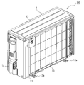
- FIG. 1 is a perspective view showing the outdoor unit of the air conditioner from the front side.
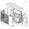
- FIG. 2 is an exploded perspective view showing the outdoor unit of the air conditioner from the front side.
- FIG. 3 is a perspective view showing the outdoor unit of the air conditioner from the back side.
- FIG. 4 is an exploded perspective view showing the outdoor unit of the air conditioner from the back side.
- the outdoor unit 110 of the air conditioner shown in FIGS. 1 to 4 includes a housing 1 forming an outer shell.
- the housing 1 is configured of, for example, a front side panel 10, a right side panel 11, a bottom panel 12, and a top panel 13.
- the front side panel 10 is, for example, an L-shaped member, and constitutes a front side and a left side of the housing 1.
- the front side panel 10 is formed with a circular air outlet, and a fan guard 10 a covering the air outlet is attached.
- the outdoor unit 110 of the air conditioner has a structure in which the leg portions 12a attached to the lower surface of the bottom panel 12 are fixed to the installation place and stabilized.
- FIG. 5 is the perspective view which showed the internal structure of the outdoor unit which abbreviate
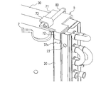
- 6 is an enlarged view of a portion A shown in FIG.
- FIG. 7 is an enlarged view of a portion A shown in FIG. 5 as viewed from the side.
- FIG. 8 is an enlarged view of a portion A shown in FIG. 5 and the periphery thereof in plan view.
- the holder 5 shown in FIG. 5 is omitted.
- the housing 1 is internally divided into a fan room 3 and a machine room 4 by a partition plate 2 disposed from the front side toward the back side.
- the partition plate 2 is curved toward the right side at an intermediate portion extending from the front side to the rear side, and heat is generated at the end of the curved surface 21 as shown in FIGS.
- a flat portion 20 is formed along the side of the exchanger 30.
- the flat surface is in contact with the side surface on the front side of the heat exchanger 30, and the shaft portion of a fastening member such as a screw is screwed into the through hole 22 provided at the end portion. It is joined.
- the partition plate 2 is formed in a shape corresponding to the width of the heat exchanger 30, and the shape is different for each of the various outdoor units.
- the blower chamber 3 is provided with a heat exchanger 30, a propeller fan 32, a motor 33, and a motor mount 34.
- the motor mount 34 is a member for holding the motor 33 to which the propeller fan 32 is attached, and is provided in front of the heat exchanger 30.
- the outdoor unit 110 is configured such that the air passing through the heat exchanger 30 is introduced into the interior by the operation of the propeller fan 32, passes through the propeller fan 32, and is discharged to the front of the outdoor unit 110.
- the outdoor unit 110 is configured such that the refrigerant is cooled by the air in the heat exchanger 30 during the cooling operation, for example, and the air having passed through the heat exchanger 30 is heated by heat exchange with the refrigerant.
- the heat exchanger 30 is configured in two rows as shown in FIG. 2, FIG. 4 and FIG. 5, and is provided along the edge on the back side of the housing 1 and the edge on the left side.
- the width dimension of the heat exchanger 30 comprised by 2 rows is about 44 mm as an example.
- the synthetic resin holder 5 containing the temperature detection means 8 for measuring the outside air temperature of the housing 1 is on the back side. It is attached to the upper left.
- the temperature detection means 8 is composed of, for example, a thermistor.
- the machine room 4 is provided with a compressor 40, a refrigerant pipe 41, an electrical component unit 42, and a power supply unit 43.
- the compressor 40 is mounted on the top surface of the bottom panel 12 and compresses the refrigerant sent from the indoor unit.
- the refrigerant compressed by the compressor 40 is sent to the heat exchanger 30 through the refrigerant pipe 41.
- the electrical component unit 42 includes a control board and the like, and is for performing power supply and the like to each component provided inside the outdoor unit 110.
- the power supply unit 43 has a configuration in which a terminal block connecting the outdoor unit 110 and the indoor unit is fixed to a power supply plate by a screw or the like.
- the power supply unit 43 communicates with the outside through an opening 11a formed in the right side panel 11 as shown in FIGS. 2 and 4, and is mounted on the outer surface of the right side panel 11 as shown in FIG. It is covered by the protective cover 14 and protected from dust or water.
- FIG. 9 is a perspective view showing a holder of the outdoor unit of the air conditioner with the cover portion opened.
- FIG. 10 is a perspective view of the holder of the outdoor unit of the air conditioner, showing a state in which the cover is closed.
- the holder 5 is connected to the housing portion 6 for housing the temperature detecting means 8 and the housing portion 6, and is pulled by the flat portion 20 across the upper surface of the heat exchanger 30. And a hooking portion 7.
- the storage portion 6 is composed of a concave main body portion 60 having a pedestal 62 for attaching the temperature detection means 8, and a cover portion 61 pivotally hingedly connected at the lower end of the main body portion 60. At both side edges of the main body 60, hooks 63 are provided which project toward the cover 61. On the other hand, on both side edges of the cover 61, engaging holes 64 for engaging the hooks 63 are formed. As shown in FIG. 10, the storage portion 6 can store the temperature detection means 8 inside by rotating the cover portion 61 and engaging the hook portion 63 with the engagement hole 64.
- the holder 5 is attached to the heat exchanger 30, the hook portion 63 is removed from the engagement hole 64, and the cover portion 61 is rotated to open the main body portion 60, whereby the temperature detection means 8 is attached. Or you can do the removal work.
- a through hole for passing the lead wire 80 of the temperature detection means 8 stored therein to the outside is formed on the upper surface of the storage portion 6.
- vent holes 65 in the form of horizontally long slits are formed at a plurality of places. The wind that has entered from the vent holes 65 of the cover portion 61 passes through the inside of the storage portion 6 and is sucked into the heat exchanger 30 through the vent holes 65 of the main body portion 60.
- the hooking portion 7 extends from the housing portion 6 and is bent from an end portion of the extending surface portion 70 coming into contact with the back surface of the heat exchanger 30 and an end portion of the extending surface portion 70 and mounted on the upper surface of the heat exchanger 30
- a top surface portion 71 and a holding portion 72 bent from an end portion of the top surface portion 71 and hooked to the flat portion 20 are provided.
- the top surface portion 71 has a length substantially equal to the width of the heat exchanger 30 configured in two rows.
- the extension surface portion 70 is formed with a recess 70 a into which the lead wire 80 of the temperature detection means 8 protected by the protective tube is fitted and fixed.
- An L-shaped guide piece 73 for holding the lead wire 80 of the temperature detection means 8 is provided on the top surface of the top surface portion 71.
- the hooking portion 72 is configured such that the tip end portion 72a is inclined outward. In this case, when attaching the holder 5 to the heat exchanger 30, the tip end portion 72a of the retaining portion 72 functions as a guide portion.
- the holder 5 is attached to the flat portion 20 by hooking the hook 7 across the upper surfaces of the two rows of heat exchangers 30. That is, the holder 5 is assembled so that the back surface side of the heat exchanger 30 and the flat portion 20 are held by the extension surface portion 70 and the hook portion 72, and the top surface portion 71 is the upper end edge of the flat portion 20 and thermal It is positioned by abutting on the upper surface of the exchanger 30. At this time, when attaching the holder 5 to the heat exchanger 30, the tip end portion 72a of the retaining portion 72 functions as a guide portion that guides the flat portion 20.
- the holding portion 72 is held on the flat portion 20 of the partition plate 2 to attach the holder 5 to the heat exchanger 30, but the present invention is not limited to this.
- the holder 5 may be attached to the heat exchanger 30 by hooking the holding portion 72 on the front side of the heat exchanger 30.
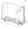
- FIG. 11 is a perspective view showing an internal structure of the outdoor unit of the air conditioner according to the present embodiment, in which the other components except the heat exchanger are omitted.
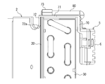
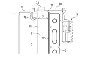
- FIG. 12 is an enlarged view of a portion B shown in FIG.
- FIG. 13 is an enlarged view of a portion B shown in FIG. 11 as viewed from the side direction.
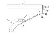
- FIG. 14 is an enlarged view of a portion B shown in FIG. 11 and the periphery thereof in plan view.
- a single row of heat exchangers 31 is provided from the edge on the back side of the housing 1 along the edge on the left side.
- the heat exchanger 31 configured in one row is, for example, configured to have a width of about 22 mm.
- the partition plate 9 used in the outdoor unit 100 of this air conditioner has a curved surface 93 that curves toward the right side in an intermediate part that goes from the front to the rear as shown in FIGS. 11 and 14. have.
- the partition plate 9 is provided at the end of the curved surface 93 with a space S between the heat exchanger 31 and the first flat portion 90 having a shape along the longitudinal direction of the heat exchanger 31, and the first flat portion 90 And a second flat portion 91 having a shape protruding toward the heat exchanger 31 from the side edge portion of the flat portion 90.
- the second flat portion 91 can provide the space S which is the width of the heat exchanger for one row, so that the air conditioning provided with the two rows of heat exchangers 30
- the same holder 5 as the holder 5 used for the outdoor unit 110 of the unit can be used for the outdoor unit 100 of the air conditioner provided with the heat exchanger 31 of one row.
- the partition plate 9 has the 3rd flat part 92 of the shape protruded along the longitudinal direction of the heat exchanger 31 from the side edge part of the 2nd flat part 91, as shown in FIG.12 and FIG.14. .
- the third flat portion 92 is in contact with the side surface on the front side of the heat exchanger 31 and is joined to the heat exchanger 31 by screwing the shaft portion of a fastening member such as a screw into the through hole 94.
- the partition plate 9 may be joined to the heat exchanger 31 by another configuration without providing the third flat portion 92.
- the holder 5 is attached to the back side of the heat exchanger 31 with the hooking portion 7 hooked on the first flat portion 90 across the top surface of the heat exchanger 31 in one row.
- the holder 5 is assembled so that the back surface side of the heat exchanger 31 and the first flat portion 90 are held by the extension surface portion 70 and the hook portion 72, and the top surface portion 71 is first flat. It is positioned by abutting the upper end edge of the portion 90 and the upper surface of the heat exchanger 31.
- the tip end portion 72 a of the retaining portion 72 functions as a guide portion when attaching the holder 5 to the heat exchanger 31.
- the same holder 5 as the holder 5 used for the outdoor unit 110 of the air conditioner provided with the heat exchangers 30 in the two rows is air provided with the heat exchanger 31 in the one row.
- the outdoor unit 100 of the air conditioner according to the present embodiment adjusts the length of the second flat portion 91 to form the partition plate 9 so that the outdoor of the air conditioner provided with the three rows of heat exchangers It is also possible to use the same holder as that used for the machine in an outdoor unit of an air conditioner equipped with a single row of heat exchangers.
- the casing 1 forming the outer shell, and the inside of the casing 1 are disposed from the front side to the back side of the casing 1 Mounted on the heat exchanger 31 and the heat exchanger 31 installed along the edge on the back side of the housing 1 inside the fan chamber 3 and the partition plate 9 for dividing the air into the fan room 3 and the machine room 4 And a holder 5 for housing the temperature detection means 8 for measuring the outside air temperature.
- the partition plate 9 is provided with a space S between the heat exchanger 31 and the back surface side, and the first flat portion 90 shaped along the longitudinal direction of the heat exchanger 31 and the side of the first flat portion 90 And a second flat portion 91 having a shape protruding toward the heat exchanger 31 from the edge.
- the holder 5 has a storage portion 6 for storing the temperature detection means 8 and a hook portion 7 continuously connected to the housing portion 6 and hooked to the first flat portion 90 across the upper surface of the heat exchanger 31. ing.
- the outdoor unit 100 of the air conditioner according to the present embodiment adjusts the length of the second flat portion 91 to form the partition plate 9 so that the first flat portion 90 and the heat exchanger 31 can be separated. Since the spacing S can be matched to the shape of the holder 5, the same holder 5 as the holder 5 used for the outdoor unit 110 provided with the heat exchangers 30 different in width can be used. Therefore, in the outdoor unit 100 of the air conditioner according to the present embodiment, when the holder 5 is manufactured, the number of manufacturing dies prepared for each shape of the holder 5 may be small, and the manufacturing cost can be suppressed. In addition, it is possible to reduce the burden of managing the holders 5 by different types.
- the partition plate 9 has a third flat portion 92 shaped to project along the longitudinal direction of the heat exchanger 31 from the side edge of the second flat portion 91. Therefore, the outdoor unit 100 of the air conditioner according to the present embodiment fixes the partition plate 9 by bringing the third flat portion 92 into contact with the heat exchanger 31 and joining the third flat portion 92 with a fastening member such as a screw. Can.
- the hooking portion 7 of the holder 5 extends from the housing portion 6 and bends from the end of the extending surface portion 70 coming in contact with the back surface of the heat exchanger 31 and the end of the extending surface portion 70.
- a top surface portion 71 placed on the upper surface, and a holding portion 72 bent from an end of the top surface portion 71 and held on the first flat portion 90 are provided.
- the hooking portion 72 is configured such that the tip end portion 72a is inclined outward. Therefore, when attaching the holder 5 to the heat exchanger 31, the outdoor unit 100 of the air conditioner according to the present embodiment functions as a guide for guiding the tip end portion 72a of the retaining portion 72 to the first flat portion 90. Therefore, the work of attaching the holder 5 becomes easy, and the workability can be improved.
- the present invention has been described above based on the embodiment, the present invention is not limited to the configuration of the embodiment described above.
- the configuration of the outdoor unit of the illustrated air conditioner is merely an example, and the present invention is not limited to the above-described content, and the same applies to an outdoor unit of an air conditioner including other components. can do.
- the scope of the various modifications, applications, and uses that the so-called person skilled in the art makes as needed is mentioned in the scope of the present invention (the technical scope).
Landscapes
- Engineering & Computer Science (AREA)
- Chemical & Material Sciences (AREA)
- Combustion & Propulsion (AREA)
- Mechanical Engineering (AREA)
- General Engineering & Computer Science (AREA)
- Other Air-Conditioning Systems (AREA)
- Air Conditioning Control Device (AREA)
Abstract
空気調和機の室外機は、外郭を形成する筐体と、筐体の前面側から背面側に向かって配置され、筐体の内部を送風機室と機械室とに仕切る仕切り板と、送風機室の内部において、筐体の背面側の縁部に沿って設置された熱交換器と、熱交換器に取り付けられ、外気温度を測定する温度検知手段を収納するホルダと、を備えている。仕切り板は、背面側において熱交換器との間に間隔をあけて設けられ、熱交換器の長手方向に沿った形状の第1平坦部と、第1平坦部の側縁部から熱交換器に向かって突き出す形状の第2平坦部と、を有している。ホルダは、温度検知手段を保持する収納部と、収納部に連設され、熱交換器の上面を跨って第1平坦部に掛け留める引掛け部と、を有する。
Description
本発明は、外気温度を測定する温度検知手段を収納するためのホルダを備えた空気調和機の室外機に関するものである。
従来、空気調和機の室外機は、外気温度を測定する温度検知手段を収納するためのホルダを備えた構成が知られている。例えば特許文献1では、外郭を形成する筐体の内部において、背面側に縁部に沿って1列又は複数列で設置された熱交換器に取り付けるホルダが開示されている。このホルダは、温度検知手段であるサーミスタを収納する本体部と、本体部に回動自在にヒンジ連結されたカバー部と、を備えている。本体部には、熱交換器の上端部を前後から挟み付けて係合する引掛け部が設けられている。
特許文献1に開示されたホルダのように、引掛け部で熱交換器の上端部を前後から挟み付けて係合させる構成では、熱交換器の幅寸に合わせて引掛け部の寸法が決定されるので、幅寸が異なる熱交換器には取り付けることができない。つまり、従来の空気調和機の室外機では、例えば2列の熱交換器を備えた空気調和機の室外機に使用されるホルダを、1列の熱交換器を備えた空気調和機の室外機に適用することができず、熱交換器の幅寸に対応するホルダを、室外機ごとに製造する必要があった。そのため、従来の空気調和機の室外機では、ホルダの形状ごとに製造金型を用意する必要があり、製造コストが嵩む虞があった。また、ホルダを異なる種類ごとに分けて管理する作業が煩わしく作業者の負担が大きかった。
本発明は、上記のような課題を解決するためになされたもので、幅寸が異なる熱交換器を備えた室外機に使用されるホルダと同一のホルダを使用することができる、空気調和機の室外機を提供することを目的とする。
本発明に係る空気調和機の室外機は、外郭を形成する筐体と、前記筐体の前面側から背面側に向かって配置され、前記筐体の内部を送風機室と機械室とに仕切る仕切り板と、前記送風機室の内部において、前記筐体の背面側の縁部に沿って設置された熱交換器と、前記熱交換器に取り付けられ、外気温度を測定する温度検知手段を収納するホルダと、を備え、前記仕切り板は、背面側において前記熱交換器との間に間隔をあけて設けられ、前記熱交換器の長手方向に沿った形状の第1平坦部と、前記第1平坦部の側縁部から前記熱交換器に向かって突き出す形状の第2平坦部と、を有し、前記ホルダは、前記温度検知手段を保持する収納部と、前記収納部に連設され、前記熱交換器の上面を跨って前記第1平坦部に掛け留める引掛け部と、を有するものである。
本発明によれば、第2平坦部の長さを調整して仕切り板を形成することで、第1平坦部と熱交換器との間隔をホルダの形状に合わせることができるので、幅寸が異なる熱交換器を備えた室外機に用いられるホルダと同一のホルダを使用することができる。
以下、図面を参照して、本発明の実施の形態について説明する。なお、各図中、同一又は相当する部分には、同一符号を付して、その説明を適宜省略または簡略化する。また、各図に記載の構成について、その形状、大きさ、及び配置等は、本発明の範囲内で適宜変更することができる。
実施の形態.
本発明の実施の形態に係る空気調和機の室外機は、幅寸が異なる熱交換器を備えた室外機に使用される温度検出手段のホルダと同一のホルダを使用することができる構成である。そこで、本実施の形態では、2列の熱交換器を備えた空気調和機の室外機110に使用されるホルダと同一のホルダを、1列の熱交換器を備えた空気調和機の室外機100に使用する場合を例に説明する。
本発明の実施の形態に係る空気調和機の室外機は、幅寸が異なる熱交換器を備えた室外機に使用される温度検出手段のホルダと同一のホルダを使用することができる構成である。そこで、本実施の形態では、2列の熱交換器を備えた空気調和機の室外機110に使用されるホルダと同一のホルダを、1列の熱交換器を備えた空気調和機の室外機100に使用する場合を例に説明する。
先ずは、図1~図10に示す2列の熱交換器を備えた空気調和機の室外機110に基づいて、本実施の形態に係る空気調和機の室外機100が有する共通の構造について説明する。図1は、空気調和機の室外機を前面側から示した斜視図である。図2は、空気調和機の室外機を前面側から示した分解斜視図である。図3は、空気調和機の室外機を背面側から示した斜視図である。図4は、空気調和機の室外機を背面側から示した分解斜視図である。
図1~図4に示す空気調和機の室外機110は、外郭を形成する筐体1を備えている。筐体1は、一例として前側面パネル10、右側面パネル11、底面パネル12、及び天面パネル13で構成されている。前側面パネル10は、例えばL字形状の部材であり、筐体1の前側面及び左側面を構成する。前側面パネル10には、円形状の吹出口が形成されており、吹出口を覆うファンガード10aが取り付けられている。空気調和機の室外機110は、底面パネル12の下面に取り付けられた脚部12aを設置場所に固定して安定させる構造となっている。
図5は、熱交換器を除く他の構成要素を省略した室外機の内部構造を示した斜視図である。図6は、図5に示したA部拡大図である。図7は、図5に示したA部を側面方向から見た拡大図である。図8は、図5に示したA部とその周辺を平面的に見た拡大図である。なお、図8では、図5に示したホルダ5を省略している。筐体1は、図5に示すように、前面側から背面側に向かって配置された仕切り板2によって、内部を送風機室3と機械室4とに区画されている。
仕切り板2は、図5に示すように、前面側から背面側に向かう中間部において、右側面側に向かって湾曲し、図6~図8に示すように、湾曲面21の終端部に熱交換器30の側面に沿った平坦部20が形成されている。平坦部20は、平坦面が熱交換器30の前面側の側面に当接されており、端部に設けた通孔22にネジ等の締結部材の軸部をネジ込んで熱交換器30に接合されている。仕切り板2は、熱交換器30の幅寸に応じた形状で構成されており、各種の室外機ごとに形状が異なっている。
送風機室3には、図2に示すように、熱交換器30、プロペラファン32、モーター33、及びモーター取付台34が設けられている。モーター取付台34は、プロペラファン32を取り付けたモーター33を保持する部材であり、熱交換器30の前方に設けられている。室外機110は、プロペラファン32が動作することで、熱交換器30を通過した空気が内部に導入されてプロペラファン32を通過し、室外機110の前方へ排出される構成である。これにより、室外機110は、例えば冷房運転中において、熱交換器30内で冷媒が空気によって冷却され、熱交換器30を通過した空気が冷媒と熱交換することで加熱される構成となる。
熱交換器30は、図2、図4及び図5に示すように2列で構成されており、筐体1の背面側の縁部から左側面の縁部に沿って設けられている。2列で構成された熱交換器30の幅寸は、一例として44mm程度である。熱交換器30には、図3、図4、図6及び図7に示すように、筐体1の外気温度を測定する温度検知手段8を収納した合成樹脂製のホルダ5が、背面側の左上に取り付けられている。温度検知手段8は、例えばサーミスタで構成される。
機械室4には、図2及び図4に示すように、圧縮機40、冷媒配管41、電装品ユニット42、及び電源ユニット43が設けられている。圧縮機40は、底面パネル12の上面に載置されており、室内機から送られた冷媒を圧縮する。圧縮機40で圧縮された冷媒は、冷媒配管41を通って熱交換器30に送られる。電装品ユニット42は、制御基板等を備えており、室外機110の内部に設けた各部品への電力供給等を行うためのものである。電源ユニット43は、室外機110と室内機とを接続する端子台が電源板にネジ等で固定された構成である。電源ユニット43は、図2及び図4に示すように、右側面パネル11に形成された開口部11aを介して外部と通じており、図1に示すように、右側面パネル11の外面に取り付けられた保護カバー14で覆われて、埃又は水が入らないように保護されている。
次に、ホルダ5の具体的な構成を図9及び図10に基づいて説明する。図9は、空気調和機の室外機のホルダであって、カバー部を開いた状態を示した斜視図である。図10は、空気調和機の室外機のホルダであって、カバー部を閉じた状態を示した斜視図である。ホルダ5は、図9及び図10に示すように、温度検知手段8を収納する収納部6と、収納部6に連設され、熱交換器30の上面を跨って平坦部20に掛け留める引掛け部7と、で構成されている。
収納部6は、温度検知手段8を取り付けるための台座62を有する凹形状の本体部60と、本体部60の下端で回動自在にヒンジ連結されたカバー部61と、で構成されている。本体部60の両側縁には、カバー部61へ向かって突き出すフック部63が設けられている。一方、カバー部61の両側縁には、フック部63を係合させる係合孔64が形成されている。収納部6は、図10に示すように、カバー部61を回動させ、フック部63を係合孔64に係合させることで、温度検知手段8を内部に収納することができる。つまり、ホルダ5は、熱交換器30に取り付けた状態で、フック部63を係合孔64から外し、カバー部61を回動させて本体部60を開放させることで、温度検知手段8の取り付け又は取り外し作業を行うことができる。なお、収納部6の上面には、収納した温度検知手段8のリード線80を外部へ通すための貫通孔が形成されている。
本体部60には、縦長のスリット状又は横長のスリット状の通気孔(図示は省略)が、複数箇所に形成されている。また、カバー部61には、横長のスリット状の通気孔65が複数箇所に形成されている。カバー部61の通気孔65から進入した風は、収納部6の内部を通過し、本体部60の通気孔65を通じて熱交換器30に吸い込まれる。
引掛け部7は、収納部6から延出し、熱交換器30の背面に当接させる延出面部70と、延出面部70の端部から屈曲され、熱交換器30の上面に載置させる天面部71と、天面部71の端部から屈曲され、平坦部20に掛け留める掛留部72と、を有している。天面部71は、2列で構成された熱交換器30の幅寸と略同一の長さで構成されている。
延出面部70には、保護チューブで保護された温度検知手段8のリード線80を嵌め込んで固定する凹部70aが形成されている。天面部71の上面には、温度検知手段8のリード線80を保持するL字状のガイド片73が設けられている。
掛留部72は、先端部72aを外方に向かって傾斜させた構成である。これは、ホルダ5を熱交換器30に取り付ける際に、掛留部72の先端部72aをガイド部として機能させるものである。
ホルダ5は、図6及び図7に示すように、引掛け部7が2列の熱交換器30の上面を跨って平坦部20に掛け留められて取り付けられる。つまり、ホルダ5は、延出面部70と掛留部72とで、熱交換器30の背面側と平坦部20とを挟み付けるように組み付けられ、天面部71が平坦部20の上端縁と熱交換器30の上面に突き当たることで位置決めされる。このとき、掛留部72の先端部72aは、ホルダ5を熱交換器30に取り付ける際に、平坦部20へ誘導するガイド部として機能する。
なお、図示した実施の形態では、掛留部72を仕切り板2の平坦部20に掛け留めてホルダ5を熱交換器30に取り付ける構成を示したが、この限りではない。ホルダ5は、掛留部72を熱交換器30の前面側の側面に掛け留めて、熱交換器30に取り付けてもよい。
次に、1列の熱交換器31を備えた空気調和機の室外機100を、図11~図14に基づいて説明する。図11は、本実施の形態に係る空気調和機の室外機であって、熱交換器を除く他の構成要素を省略した内部構造を示した斜視図である。図12は、図11に示したB部拡大図である。図13は、図11に示したB部を側面方向から見た拡大図である。図14は、図11に示したB部とその周辺を平面的に見た拡大図である。
空気調和機の室外機100は、図11~図13に示すように、1列の熱交換器31が筐体1の背面側の縁部から左側面の縁部に沿って設けられている。1列で構成された熱交換器31は、一例として22mm程度の幅寸で構成されている。
この空気調和機の室外機100に使用されている仕切り板9は、図11及び図14に示すように、前面側から背面側に向かう中間部に、右側面側に向かって湾曲する湾曲面93を有している。仕切り板9は、湾曲面93の終端部において、熱交換器31との間に間隔Sをあけて設けられ、熱交換器31の長手方向に沿った形状の第1平坦部90と、第1平坦部90の側縁部から熱交換器31に向かって突き出す形状の第2平坦部91と、を有している。仕切り板9は、第2平坦部91の大きさを調整して形成することで、第1平坦部90と熱交換器31との間に目標の間隔Sを形成することができる。つまり、本実施の形態の場合では、第2平坦部91によって、1列分の熱交換器の幅寸となる間隔Sを設けることができるので、2列の熱交換器30を備えた空気調和機の室外機110に使用されるホルダ5と同一のホルダ5を、1列の熱交換器31を備えた空気調和機の室外機100に使用することができる。
また、仕切り板9は、図12及び図14に示すように、第2平坦部91の側縁部から熱交換器31の長手方向に沿って突き出す形状の第3平坦部92を有している。第3平坦部92は、熱交換器31の前面側の側面に当接しており、通孔94にネジ等の締結部材の軸部をネジ込んで熱交換器31に接合されている。なお、仕切り板9は、第3平坦部92を設けることなく、他の構成によって熱交換器31に接合される構成でもよい。
ホルダ5は、図12及び図13に示すように、引掛け部7が1列の熱交換器31の上面を跨って第1平坦部90に掛け留められて熱交換器31の背面側に取り付けられる。具体的には、ホルダ5は、延出面部70と掛留部72とで、熱交換器31の背面側と第1平坦部90とを挟み付けるように組み付けられ、天面部71が第1平坦部90の上端縁と熱交換器31の上面に突き当たることで位置決めされる。なお、掛留部72の先端部72aは、ホルダ5を熱交換器31へ取り付ける際のガイド部として機能する。
なお、図示した実施の形態では、2列の熱交換器30を備えた空気調和機の室外機110に使用されるホルダ5と同一のホルダ5を、1列の熱交換器31を備えた空気調和機の室外機100に使用できる場合を例に説明したが、この限りではない。本実施の形態に係る空気調和機の室外機100は、第2平坦部91の長さを調整して仕切り板9を形成することで、3列の熱交換器を備えた空気調和機の室外機に使用されるホルダと同一のホルダを、1列の熱交換器を備えた空気調和機の室外機に使用することもできる。また、1列の熱交換器を備えた空気調和機の室外機に用いられるホルダと同一のホルダを、幅寸が異なる1列の熱交換器を備えた空気調和機の室外機に使用することもできる。
上記したように、本実施の形態の空気調和機の室外機100によれば、外郭を形成する筐体1と、筐体1の前面側から背面側に向かって配置され、筐体1の内部を送風機室3と機械室4とに仕切る仕切り板9と、送風機室3の内部において、筐体1の背面側の縁部に沿って設置された熱交換器31と、熱交換器31に取り付けられ、外気温度を測定する温度検知手段8を収納するホルダ5と、を備えている。仕切り板9は、背面側において熱交換器31との間に間隔Sをあけて設けられ、熱交換器31の長手方向に沿った形状の第1平坦部90と、第1平坦部90の側縁部から熱交換器31に向かって突き出す形状の第2平坦部91と、を有している。ホルダ5は、温度検知手段8を収納する収納部6と、収納部6に連設され、熱交換器31の上面を跨って第1平坦部90に掛け留める引掛け部7と、を有している。
よって、本実施の形態に係る空気調和機の室外機100は、第2平坦部91の長さを調整して仕切り板9を形成することで、第1平坦部90と熱交換器31との間隔Sをホルダ5の形状に合わせることができるので、幅寸が異なる熱交換器30を備えた室外機110に使用されるホルダ5と同一のホルダ5を使用することができる。そのため、本実施の形態の空気調和機の室外機100では、ホルダ5を製造する際に、ホルダ5の形状ごとに用意する製造金型が少なくて済み、製造コストを抑えることができる。また、ホルダ5を異なる種類ごとに分けて管理する負担も軽減できる。
また、仕切り板9は、第2平坦部91の側縁部から熱交換器31の長手方向に沿って突き出す形状の第3平坦部92を有している。よって、本実施の形態の空気調和機の室外機100は、第3平坦部92を熱交換器31に当接させて、ネジ等の締結部材で接合することにより、仕切り板9を固定することができる。
また、ホルダ5の引掛け部7は、収納部6から延出し、熱交換器31の背面に当接させる延出面部70と、延出面部70の端部から屈曲し、熱交換器31の上面に載置させる天面部71と、天面部71の端部から屈曲し、第1平坦部90に掛け留める掛留部72と、を有している。掛留部72は、先端部72aを外方に向かって傾斜させた構成である。よって、本実施の形態の空気調和機の室外機100は、ホルダ5を熱交換器31に取り付ける際に、掛留部72の先端部72aが第1平坦部90に誘導するガイド部として機能するので、ホルダ5を取り付ける作業が容易となり、作業性を向上させることができる。
以上に本発明を実施の形態に基づいて説明したが、本発明は上述した実施の形態の構成に限定されるものではない。例えば、図示した空気調和機の室外機の構成は、一例であって、上述した内容に限定されるものではなく、他の構成要素を含んだ空気調和機の室外機であっても同様に実施することができる。要するに、いわゆる当業者が必要に応じてなす種々なる変更、応用、利用の範囲をも本発明の要旨(技術的範囲)に含むことを念のため申し添える。
1 筐体、2 仕切り板、3 送風機室、4 機械室、5 ホルダ、6 収納部、7 引掛け部、8 温度検知手段、9 仕切り板、10 前側面パネル、10a ファンガード、11 右側面パネル、11a 開口部、12 底面パネル、12a 脚部、13 天面パネル、14 保護カバー、20 平坦部、21 湾曲面、22 通孔、30、31 熱交換器、32 プロペラファン、33 モーター、34 モーター取付台、40 圧縮機、41 冷媒配管、42 電装品ユニット、43 電源ユニット、60 本体部、61 カバー部、62 台座、63 フック部、64 係合孔、65 通気孔、70 延出面部、70a 凹部、71 天面部、72 掛留部、72a 先端部、73 ガイド片、80 リード線、90 第1平坦部、91 第2平坦部、92 第3平坦部、93 湾曲面、94 通孔、100、110 空気調和機の室外機。
Claims (3)
- 外郭を形成する筐体と、
前記筐体の前面側から背面側に向かって配置され、前記筐体の内部を送風機室と機械室とに仕切る仕切り板と、
前記送風機室の内部において、前記筐体の背面側の縁部に沿って設置された熱交換器と、
前記熱交換器に取り付けられ、外気温度を測定する温度検知手段を収納するホルダと、を備え、
前記仕切り板は、
背面側において前記熱交換器との間に間隔をあけて設けられ、前記熱交換器の長手方向に沿った形状の第1平坦部と、
前記第1平坦部の側縁部から前記熱交換器に向かって突き出す形状の第2平坦部と、を有し、
前記ホルダは、
前記温度検知手段を保持する収納部と、
前記収納部に連設され、前記熱交換器の上面を跨って前記第1平坦部に掛け留める引掛け部と、を有する、空気調和機の室外機。 - 前記仕切り板は、前記第2平坦部の側縁部から前記熱交換器の長手方向に沿って突き出す形状の第3平坦部を、更に有している、請求項1に記載の空気調和機の室外機。
- 前記ホルダの前記引掛け部は、
前記収納部から延出し、前記熱交換器の背面に当接させる延出面部と、
前記延出面部の端部から屈曲し、前記熱交換器の上面に載置させる天面部と、
前記天面部の端部から屈曲し、前記第1平坦部に掛け留める掛留部と、を有し、
前記掛留部は、先端部を外方に向かって傾斜させた構成である、請求項1又は2に記載の空気調和機の室外機。
Priority Applications (5)
| Application Number | Priority Date | Filing Date | Title |
|---|---|---|---|
| JP2019532270A JP6727442B2 (ja) | 2017-07-26 | 2017-07-26 | 空気調和機の室外機 |
| PCT/JP2017/027074 WO2019021395A1 (ja) | 2017-07-26 | 2017-07-26 | 空気調和機の室外機 |
| EP17919377.6A EP3660410B1 (en) | 2017-07-26 | 2017-07-26 | Outdoor unit for air conditioner |
| US16/616,614 US11306926B2 (en) | 2017-07-26 | 2017-07-26 | Outdoor unit of air-conditioning apparatus |
| CN201780092482.XA CN110914601B (zh) | 2017-07-26 | 2017-07-26 | 空调机的室外机 |
Applications Claiming Priority (1)
| Application Number | Priority Date | Filing Date | Title |
|---|---|---|---|
| PCT/JP2017/027074 WO2019021395A1 (ja) | 2017-07-26 | 2017-07-26 | 空気調和機の室外機 |
Publications (1)
| Publication Number | Publication Date |
|---|---|
| WO2019021395A1 true WO2019021395A1 (ja) | 2019-01-31 |
Family
ID=65039549
Family Applications (1)
| Application Number | Title | Priority Date | Filing Date |
|---|---|---|---|
| PCT/JP2017/027074 Ceased WO2019021395A1 (ja) | 2017-07-26 | 2017-07-26 | 空気調和機の室外機 |
Country Status (5)
| Country | Link |
|---|---|
| US (1) | US11306926B2 (ja) |
| EP (1) | EP3660410B1 (ja) |
| JP (1) | JP6727442B2 (ja) |
| CN (1) | CN110914601B (ja) |
| WO (1) | WO2019021395A1 (ja) |
Families Citing this family (2)
| Publication number | Priority date | Publication date | Assignee | Title |
|---|---|---|---|---|
| JP7595251B2 (ja) * | 2020-05-29 | 2024-12-06 | パナソニックIpマネジメント株式会社 | 空気調和装置 |
| CN115978654B (zh) * | 2022-11-30 | 2024-08-16 | 青岛海尔空调器有限总公司 | 用于空调的室外机和空调 |
Citations (4)
| Publication number | Priority date | Publication date | Assignee | Title |
|---|---|---|---|---|
| JP2001355874A (ja) * | 2000-06-15 | 2001-12-26 | Sharp Corp | 空気調和機の室外機 |
| JP2007147205A (ja) | 2005-11-30 | 2007-06-14 | Mitsubishi Electric Corp | 空気調和機の室外ユニット |
| JP2008121949A (ja) * | 2006-11-10 | 2008-05-29 | Matsushita Electric Ind Co Ltd | 空気調和機の室外機 |
| JP2017083095A (ja) * | 2015-10-29 | 2017-05-18 | 東芝キヤリア株式会社 | 空気調和機の室外機 |
Family Cites Families (11)
| Publication number | Priority date | Publication date | Assignee | Title |
|---|---|---|---|---|
| JPH0712394A (ja) | 1993-06-23 | 1995-01-17 | Matsushita Refrig Co Ltd | 外気温度センサの取付方法 |
| JP3354475B2 (ja) * | 1998-02-26 | 2002-12-09 | シャープ株式会社 | 空気調和機の室外ユニット |
| JP2003185191A (ja) * | 2001-12-20 | 2003-07-03 | Fujitsu General Ltd | 空気調和機の室外機 |
| JP2006220361A (ja) * | 2005-02-10 | 2006-08-24 | Sanyo Electric Co Ltd | 空気調和装置 |
| CN101307933A (zh) * | 2007-05-18 | 2008-11-19 | 乐金电子(天津)电器有限公司 | 空调器室外机的温度传感器固定结构 |
| JP2009174760A (ja) * | 2008-01-23 | 2009-08-06 | Daikin Ind Ltd | 室外機 |
| JP5213844B2 (ja) * | 2009-12-28 | 2013-06-19 | 三菱電機株式会社 | 空気調和機の室外機 |
| JP5246325B2 (ja) * | 2011-12-28 | 2013-07-24 | ダイキン工業株式会社 | 冷凍装置の室外ユニット |
| JP2014047996A (ja) * | 2012-09-03 | 2014-03-17 | Hitachi Appliances Inc | 空気調和機 |
| CN203404869U (zh) * | 2013-07-19 | 2014-01-22 | 广州华凌制冷设备有限公司 | 用于空调器室外机的测温组件及具有其的空调器室外机 |
| JP6387527B2 (ja) * | 2015-06-29 | 2018-09-12 | パナソニックIpマネジメント株式会社 | 空気調和機の室外機 |
-
2017
- 2017-07-26 EP EP17919377.6A patent/EP3660410B1/en not_active Not-in-force
- 2017-07-26 CN CN201780092482.XA patent/CN110914601B/zh not_active Expired - Fee Related
- 2017-07-26 US US16/616,614 patent/US11306926B2/en active Active
- 2017-07-26 JP JP2019532270A patent/JP6727442B2/ja not_active Expired - Fee Related
- 2017-07-26 WO PCT/JP2017/027074 patent/WO2019021395A1/ja not_active Ceased
Patent Citations (4)
| Publication number | Priority date | Publication date | Assignee | Title |
|---|---|---|---|---|
| JP2001355874A (ja) * | 2000-06-15 | 2001-12-26 | Sharp Corp | 空気調和機の室外機 |
| JP2007147205A (ja) | 2005-11-30 | 2007-06-14 | Mitsubishi Electric Corp | 空気調和機の室外ユニット |
| JP2008121949A (ja) * | 2006-11-10 | 2008-05-29 | Matsushita Electric Ind Co Ltd | 空気調和機の室外機 |
| JP2017083095A (ja) * | 2015-10-29 | 2017-05-18 | 東芝キヤリア株式会社 | 空気調和機の室外機 |
Non-Patent Citations (1)
| Title |
|---|
| See also references of EP3660410A4 |
Also Published As
| Publication number | Publication date |
|---|---|
| EP3660410A4 (en) | 2020-08-26 |
| CN110914601B (zh) | 2021-07-16 |
| JPWO2019021395A1 (ja) | 2019-11-07 |
| US11306926B2 (en) | 2022-04-19 |
| JP6727442B2 (ja) | 2020-07-22 |
| EP3660410B1 (en) | 2021-09-29 |
| US20200182492A1 (en) | 2020-06-11 |
| EP3660410A1 (en) | 2020-06-03 |
| CN110914601A (zh) | 2020-03-24 |
Similar Documents
| Publication | Publication Date | Title |
|---|---|---|
| JP6134855B2 (ja) | 空気調和機 | |
| JP6299552B2 (ja) | 天井埋込型空気調和機 | |
| WO2019021395A1 (ja) | 空気調和機の室外機 | |
| JP6242245B2 (ja) | 空気調和機の室内機 | |
| JP2011102654A (ja) | ダクト型空気調和機 | |
| CN106016544B (zh) | 支撑防护件及空调一体机 | |
| JP6319064B2 (ja) | 天井埋込型空気調和機 | |
| JP6207479B2 (ja) | 空気調和機の室内機、及び、空気調和機の室内機の製造方法 | |
| JP5293567B2 (ja) | ダクト型空気調和機 | |
| US20240328663A1 (en) | Decorative panel and embedded ventilation fan including the same | |
| CN216409410U (zh) | 底部设置散热机仓的冰箱 | |
| JP5031406B2 (ja) | 冷却貯蔵庫 | |
| JP6264264B2 (ja) | 天井埋込型空気調和機 | |
| JP4081681B2 (ja) | 室内機本体及び空気調和機 | |
| JPWO2018078836A1 (ja) | 空気調和装置の室外機 | |
| JP6331935B2 (ja) | 天井埋込型空気調和機 | |
| CN208442967U (zh) | 空调机的室外机 | |
| JP6755404B2 (ja) | 空気調和機の室内機 | |
| JP2006220361A (ja) | 空気調和装置 | |
| CN213019926U (zh) | 空调室内机 | |
| CN213019927U (zh) | 空调室内机 | |
| JP5473504B2 (ja) | 室内機用コントロールボックス | |
| JP6639525B2 (ja) | 空気調和装置の室内機 | |
| JP2013032862A (ja) | 空気調和機の感温素子取付構造 | |
| KR20090027356A (ko) | 공기조화기 |
Legal Events
| Date | Code | Title | Description |
|---|---|---|---|
| 121 | Ep: the epo has been informed by wipo that ep was designated in this application |
Ref document number: 17919377 Country of ref document: EP Kind code of ref document: A1 |
|
| ENP | Entry into the national phase |
Ref document number: 2019532270 Country of ref document: JP Kind code of ref document: A |
|
| NENP | Non-entry into the national phase |
Ref country code: DE |
|
| ENP | Entry into the national phase |
Ref document number: 2017919377 Country of ref document: EP Effective date: 20200226 |