WO2019021538A1 - 超音波検査システムの製造方法 - Google Patents
超音波検査システムの製造方法 Download PDFInfo
- Publication number
- WO2019021538A1 WO2019021538A1 PCT/JP2018/014307 JP2018014307W WO2019021538A1 WO 2019021538 A1 WO2019021538 A1 WO 2019021538A1 JP 2018014307 W JP2018014307 W JP 2018014307W WO 2019021538 A1 WO2019021538 A1 WO 2019021538A1
- Authority
- WO
- WIPO (PCT)
- Prior art keywords
- ultrasonic
- simulated
- waveform
- defect
- inspection
- Prior art date
- Legal status (The legal status is an assumption and is not a legal conclusion. Google has not performed a legal analysis and makes no representation as to the accuracy of the status listed.)
- Ceased
Links
Images



Classifications
-
- G—PHYSICS
- G01—MEASURING; TESTING
- G01N—INVESTIGATING OR ANALYSING MATERIALS BY DETERMINING THEIR CHEMICAL OR PHYSICAL PROPERTIES
- G01N29/00—Investigating or analysing materials by the use of ultrasonic, sonic or infrasonic waves; Visualisation of the interior of objects by transmitting ultrasonic or sonic waves through the object
- G01N29/04—Analysing solids
- G01N29/041—Analysing solids on the surface of the material, e.g. using Lamb, Rayleigh or shear waves
-
- G—PHYSICS
- G01—MEASURING; TESTING
- G01N—INVESTIGATING OR ANALYSING MATERIALS BY DETERMINING THEIR CHEMICAL OR PHYSICAL PROPERTIES
- G01N29/00—Investigating or analysing materials by the use of ultrasonic, sonic or infrasonic waves; Visualisation of the interior of objects by transmitting ultrasonic or sonic waves through the object
- G01N29/34—Generating the ultrasonic, sonic or infrasonic waves, e.g. electronic circuits specially adapted therefor
- G01N29/348—Generating the ultrasonic, sonic or infrasonic waves, e.g. electronic circuits specially adapted therefor with frequency characteristics, e.g. single frequency signals, chirp signals
-
- B—PERFORMING OPERATIONS; TRANSPORTING
- B64—AIRCRAFT; AVIATION; COSMONAUTICS
- B64F—GROUND OR AIRCRAFT-CARRIER-DECK INSTALLATIONS SPECIALLY ADAPTED FOR USE IN CONNECTION WITH AIRCRAFT; DESIGNING, MANUFACTURING, ASSEMBLING, CLEANING, MAINTAINING OR REPAIRING AIRCRAFT, NOT OTHERWISE PROVIDED FOR; HANDLING, TRANSPORTING, TESTING OR INSPECTING AIRCRAFT COMPONENTS, NOT OTHERWISE PROVIDED FOR
- B64F5/00—Designing, manufacturing, assembling, cleaning, maintaining or repairing aircraft, not otherwise provided for; Handling, transporting, testing or inspecting aircraft components, not otherwise provided for
-
- B—PERFORMING OPERATIONS; TRANSPORTING
- B64—AIRCRAFT; AVIATION; COSMONAUTICS
- B64F—GROUND OR AIRCRAFT-CARRIER-DECK INSTALLATIONS SPECIALLY ADAPTED FOR USE IN CONNECTION WITH AIRCRAFT; DESIGNING, MANUFACTURING, ASSEMBLING, CLEANING, MAINTAINING OR REPAIRING AIRCRAFT, NOT OTHERWISE PROVIDED FOR; HANDLING, TRANSPORTING, TESTING OR INSPECTING AIRCRAFT COMPONENTS, NOT OTHERWISE PROVIDED FOR
- B64F5/00—Designing, manufacturing, assembling, cleaning, maintaining or repairing aircraft, not otherwise provided for; Handling, transporting, testing or inspecting aircraft components, not otherwise provided for
- B64F5/10—Manufacturing or assembling aircraft, e.g. jigs therefor
-
- G—PHYSICS
- G01—MEASURING; TESTING
- G01N—INVESTIGATING OR ANALYSING MATERIALS BY DETERMINING THEIR CHEMICAL OR PHYSICAL PROPERTIES
- G01N29/00—Investigating or analysing materials by the use of ultrasonic, sonic or infrasonic waves; Visualisation of the interior of objects by transmitting ultrasonic or sonic waves through the object
- G01N29/04—Analysing solids
-
- G—PHYSICS
- G01—MEASURING; TESTING
- G01N—INVESTIGATING OR ANALYSING MATERIALS BY DETERMINING THEIR CHEMICAL OR PHYSICAL PROPERTIES
- G01N29/00—Investigating or analysing materials by the use of ultrasonic, sonic or infrasonic waves; Visualisation of the interior of objects by transmitting ultrasonic or sonic waves through the object
- G01N29/04—Analysing solids
- G01N29/043—Analysing solids in the interior, e.g. by shear waves
-
- G—PHYSICS
- G01—MEASURING; TESTING
- G01N—INVESTIGATING OR ANALYSING MATERIALS BY DETERMINING THEIR CHEMICAL OR PHYSICAL PROPERTIES
- G01N29/00—Investigating or analysing materials by the use of ultrasonic, sonic or infrasonic waves; Visualisation of the interior of objects by transmitting ultrasonic or sonic waves through the object
- G01N29/22—Details, e.g. general constructional or apparatus details
- G01N29/223—Supports, positioning or alignment in fixed situation
-
- G—PHYSICS
- G01—MEASURING; TESTING
- G01N—INVESTIGATING OR ANALYSING MATERIALS BY DETERMINING THEIR CHEMICAL OR PHYSICAL PROPERTIES
- G01N29/00—Investigating or analysing materials by the use of ultrasonic, sonic or infrasonic waves; Visualisation of the interior of objects by transmitting ultrasonic or sonic waves through the object
- G01N29/44—Processing the detected response signal, e.g. electronic circuits specially adapted therefor
- G01N29/4409—Processing the detected response signal, e.g. electronic circuits specially adapted therefor by comparison
- G01N29/4436—Processing the detected response signal, e.g. electronic circuits specially adapted therefor by comparison with a reference signal
-
- G—PHYSICS
- G01—MEASURING; TESTING
- G01N—INVESTIGATING OR ANALYSING MATERIALS BY DETERMINING THEIR CHEMICAL OR PHYSICAL PROPERTIES
- G01N29/00—Investigating or analysing materials by the use of ultrasonic, sonic or infrasonic waves; Visualisation of the interior of objects by transmitting ultrasonic or sonic waves through the object
- G01N29/44—Processing the detected response signal, e.g. electronic circuits specially adapted therefor
- G01N29/4472—Mathematical theories or simulation
-
- G—PHYSICS
- G01—MEASURING; TESTING
- G01N—INVESTIGATING OR ANALYSING MATERIALS BY DETERMINING THEIR CHEMICAL OR PHYSICAL PROPERTIES
- G01N29/00—Investigating or analysing materials by the use of ultrasonic, sonic or infrasonic waves; Visualisation of the interior of objects by transmitting ultrasonic or sonic waves through the object
- G01N29/44—Processing the detected response signal, e.g. electronic circuits specially adapted therefor
- G01N29/46—Processing the detected response signal, e.g. electronic circuits specially adapted therefor by spectral analysis, e.g. Fourier analysis or wavelet analysis
-
- G—PHYSICS
- G01—MEASURING; TESTING
- G01N—INVESTIGATING OR ANALYSING MATERIALS BY DETERMINING THEIR CHEMICAL OR PHYSICAL PROPERTIES
- G01N2291/00—Indexing codes associated with group G01N29/00
- G01N2291/02—Indexing codes associated with the analysed material
- G01N2291/023—Solids
- G01N2291/0231—Composite or layered materials
-
- G—PHYSICS
- G01—MEASURING; TESTING
- G01N—INVESTIGATING OR ANALYSING MATERIALS BY DETERMINING THEIR CHEMICAL OR PHYSICAL PROPERTIES
- G01N2291/00—Indexing codes associated with group G01N29/00
- G01N2291/10—Number of transducers
- G01N2291/105—Number of transducers two or more emitters, two or more receivers
-
- G—PHYSICS
- G01—MEASURING; TESTING
- G01N—INVESTIGATING OR ANALYSING MATERIALS BY DETERMINING THEIR CHEMICAL OR PHYSICAL PROPERTIES
- G01N2291/00—Indexing codes associated with group G01N29/00
- G01N2291/10—Number of transducers
- G01N2291/106—Number of transducers one or more transducer arrays
-
- G—PHYSICS
- G01—MEASURING; TESTING
- G01N—INVESTIGATING OR ANALYSING MATERIALS BY DETERMINING THEIR CHEMICAL OR PHYSICAL PROPERTIES
- G01N2291/00—Indexing codes associated with group G01N29/00
- G01N2291/26—Scanned objects
- G01N2291/263—Surfaces
- G01N2291/2634—Surfaces cylindrical from outside
-
- G—PHYSICS
- G01—MEASURING; TESTING
- G01N—INVESTIGATING OR ANALYSING MATERIALS BY DETERMINING THEIR CHEMICAL OR PHYSICAL PROPERTIES
- G01N2291/00—Indexing codes associated with group G01N29/00
- G01N2291/26—Scanned objects
- G01N2291/269—Various geometry objects
- G01N2291/2694—Wings or other aircraft parts
Definitions
- Embodiments of the present invention relate to an ultrasonic inspection system manufacturing method, an ultrasonic inspection system design system, an ultrasonic inspection system design program, an aircraft structure manufacturing method, an ultrasonic inspection system, and an aircraft structure.
- ultrasonic inspection is known as a method for nondestructively inspecting a defect of an object (see, for example, Patent Documents 1 to 3).
- the inspection area is wide as in an aircraft structure, it is necessary to arrange a plurality of ultrasonic transducers and ultrasonic sensors so as to cover the inspection area.
- the number of parts increases as the number of ultrasonic transducers and ultrasonic sensors increases, it is preferable that the number of ultrasonic transducers and ultrasonic sensors be small.
- the increase in the number of ultrasonic transducers and ultrasonic sensors leads to an increase in the weight of the airframe.
- the inspection area may not be covered, and a defect to be detected may not be detected. That is, improper arrangement of the ultrasonic transducers and ultrasonic sensors leads to deterioration of the detection accuracy of the defect. Therefore, it is important to place the ultrasound transducers and sensors at appropriate positions so that the examination area is covered reliably.
- an object of the present invention is to enable ultrasonic inspection to be performed with higher accuracy with fewer components.
- a method of manufacturing an ultrasonic inspection system includes an ultrasonic inspection target for detecting the presence or absence of a defect by an ultrasonic inspection system including at least one ultrasonic sensor and at least one ultrasonic transducer.
- An optimization calculation including simulation of the ultrasonic inspection using a simulated model, wherein the number of ultrasonic sensors, the position of the ultrasonic sensors, the direction of the ultrasonic sensors, the number of ultrasonic transducers,
- the ultrasonic sensor by performing the optimization calculation using at least one of the position of the ultrasonic transducer, the direction of the ultrasonic transducer, and the frequency of ultrasonic waves oscillated from the ultrasonic transducer as parameters.
- the number of ultrasonic sensors, the direction of ultrasonic sensors, the number of ultrasonic transducers, the position of ultrasonic transducers, the direction of ultrasonic transducers, and It has a step of creating a design information of the ultrasound system including an ultrasound frequency oscillated from the ultrasonic transducer, and a step of assembling the ultrasound system based on the design information.
- a design system of an ultrasonic inspection system has a modeling unit and a design information creation unit.
- the modeling unit creates a model that simulates an ultrasonic inspection target for detecting the presence or absence of a defect by an ultrasonic inspection system including at least one ultrasonic sensor and at least one ultrasonic transducer.
- the design information generation unit includes the number of ultrasonic sensors, the position of the ultrasonic sensors, the direction of the ultrasonic sensors, the number of ultrasonic transducers, the position of the ultrasonic transducers, and the direction of the ultrasonic transducers.
- the number of the ultrasonic sensors by performing optimization calculation including simulation of the ultrasonic inspection using the model with at least one of the frequency of ultrasonic waves oscillated from the ultrasonic transducer as a parameter.
- Position of ultrasonic sensor, direction of ultrasonic sensor, number of ultrasonic transducers, position of ultrasonic transducer, direction of ultrasonic transducer, and frequency of ultrasonic waves oscillated from ultrasonic transducer Creating design information of the ultrasound system including:
- a design program of an ultrasonic inspection system is a method for detecting the presence or absence of a defect with an ultrasonic inspection system including at least one ultrasonic sensor and at least one ultrasonic transducer in a computer.
- the number of ultrasonic sensors, the position of the ultrasonic sensors, the direction of the ultrasonic sensors, the number of ultrasonic transducers, the number of ultrasonic transducers Location, wherein in which and a step of creating the orientation and the design information of the ultrasound system including an ultrasound frequency emitted from the ultrasonic transducer of the ultrasonic vibrator.
- a method of manufacturing an aircraft structure according to an embodiment of the present invention is to assemble the ultrasonic inspection system assembled by the above-described method of manufacturing an ultrasonic inspection system into an aircraft structure.
- An ultrasonic inspection system includes an ultrasonic transducer, an ultrasonic sensor, and a signal processing system.
- the ultrasonic transducer oscillates ultrasonic waves toward a target area of ultrasonic inspection.
- the ultrasonic sensor detects at least one of a transmitted wave of the ultrasonic wave transmitted through the target area and a reflected wave of the ultrasonic wave reflected by the target area, and outputs an ultrasonic detection signal.
- the signal processing system detects a waveform change from the reference waveform of the ultrasonic wave detection signal, and detects whether or not a defect has occurred in the target area based on the detected waveform change.
- At least one of the ultrasonic transducer and the ultrasonic sensor is a defect caused at an uncertain position in the target area among a plurality of sections virtually provided on the surface of the object to be subjected to the ultrasonic inspection.
- the signal processing system is disposed in the section where the probability of occurrence of a waveform change detectable in the ultrasonic detection signal is highest.
- an ultrasonic inspection system includes at least one ultrasonic transducer, at least one ultrasonic sensor, and a signal processing system.
- the ultrasound transducer is an area of interest for ultrasound examination and emits ultrasound toward the area of interest having a web and a flange.
- the ultrasonic sensor detects at least one of a transmitted wave of the ultrasonic wave transmitted through the target area and a reflected wave of the ultrasonic wave reflected by the target area, and outputs an ultrasonic detection signal.
- the signal processing system detects a waveform change from the reference waveform of the ultrasonic wave detection signal, and detects whether or not a defect has occurred in the target area based on the detected waveform change.
- the number and the position of the ultrasonic transducer and the ultrasonic sensor are such that the waveform change of the ultrasonic detection signal caused by the defect is detected by the signal processing system regardless of the position in the target area where the defect occurs. Is the number and location where
- An aircraft structure according to an embodiment of the present invention is provided with the above-described ultrasonic inspection system.
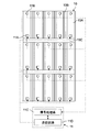
- FIG. 3 is a bottom view of the ultrasound inspection system and aircraft structure shown in FIG. 2;
- FIG. 7 is a view showing an example of optimizing the position of the ultrasonic sensor by performing ultrasonic wave propagation analysis simulation using the FEM model created in the modeling unit of the design system shown in FIG. 1.
- the graph which shows an example of the ultrasonic detection signal which penetrated the inspection field without damage.
- the graph which shows an example of the ultrasonic detection signal which permeate
- the flowchart which shows an example of the flow of the optimization calculation performed by the design system of the ultrasonic inspection system shown in FIG.
- the flowchart which shows an example of the algorithm for determining whether the simulated waveform of the ultrasonic wave changed by the simulated defect in each section set with respect to the FEM model as illustrated in FIG.
- FIG. 1 is a functional block diagram of a design system of an ultrasonic inspection system according to an embodiment of the present invention.
- the design system 1 of the ultrasonic inspection system is a system that performs an optimal design of an ultrasonic inspection system including at least one ultrasonic sensor and at least one ultrasonic transducer.
- the design system 1 of the ultrasonic inspection system includes the number of ultrasonic sensors, the position of ultrasonic sensors, the direction of ultrasonic sensors, the number of ultrasonic transducers, the position of ultrasonic transducers, and ultrasonic vibration.
- the number of ultrasonic sensors, the position of ultrasonic sensors, the direction of ultrasonic sensors by performing optimization calculation using at least one of the orientation of the transducer and the frequency of the ultrasonic waves oscillated from the ultrasonic transducers as parameters.
- Has a function to create design information of an ultrasonic inspection system including the number of ultrasonic transducers, the position of ultrasonic transducers, the orientation of ultrasonic transducers, and the frequency of ultrasonic waves oscillated from ultrasonic transducers There is.
- the design system 1 of the ultrasonic inspection system can be constructed by causing the computer 4 provided with the input device 2 and the display device 3 to read the design program of the ultrasonic inspection system. That is, the design system 1 of the ultrasonic inspection system can be configured by information processing circuits.
- the design system 1 of the ultrasonic inspection system can cause the computer 4 to function as the modeling unit 5 and the design information generation unit 6 by causing the computer 4 to read the design program of the ultrasonic inspection system. .
- the modeling unit 5 has a function of creating a model that simulates an ultrasonic inspection target for detecting the presence or absence of a defect by the ultrasonic inspection system.
- the design information generation unit 6 determines the number of ultrasonic sensors, the position of the ultrasonic sensors, and the ultrasonic waves. Function to create design information of ultrasonic inspection system including sensor orientation, number of ultrasonic transducers, position of ultrasonic transducers, orientation of ultrasonic transducers and frequency of ultrasonic waves oscillated from ultrasonic transducers Have.
- the design program of the ultrasonic inspection system at least includes the steps of creating a model simulating the target of the ultrasonic inspection, and performing the optimization calculation including the simulation of the ultrasonic inspection to obtain the design information of the ultrasonic inspection system.
- a program that causes the computer 4 to execute the step of creating The design program of the ultrasonic inspection system installed in the information processing circuits can be recorded on an information recording medium and distributed as a program product.
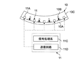
- FIG. 2 is a front view showing an example of an ultrasonic inspection system to be designed by the design system 1 shown in FIG. 1 and an aircraft structure to be an object of ultrasonic inspection
- FIG. 3 is an ultrasonic inspection shown in FIG.
- FIG. 1 is a bottom view of a system and an aircraft structure.
- the ultrasonic inspection system 11 can be mounted on the aircraft structure 10. Then, the aircraft structure 10 can be an object of ultrasonic inspection by the ultrasonic inspection system 11. That is, ultrasonic inspection by the ultrasonic inspection system 11 can detect defects that may occur in the aircraft structure 10.
- defects to be detected include damage caused by collision of birds and stones, dents, breakage of fibers constituting composite material, peeling between fiber reinforced resin layers constituting composite material, burnt by lightning, fasteners Dropout and slackness.
- the aircraft structure 10 has a structure in which a plurality of stringers 10B and a plurality of frames 10C are attached to a curved panel 10A.
- the plurality of stringers 10B and the plurality of frames 10C are attached to the panel 10A such that the longitudinal directions are substantially orthogonal to each other.
- the stringers 10B and the frames 10C are arranged such that the lengthwise direction is substantially parallel, but the plurality of stringers 10B are arranged such that the lengthwise direction of the stringer 10B and the lengthwise direction of the frame 10C are substantially perpendicular.
- a plurality of frames 10C are attached to the curved panel 10A.
- An aircraft structure 10 having such a structure is adopted as a structure that mainly constitutes a part of a fuselage.
- a structure having a reinforcing member attached to a plate-like member such as a panel 10A having the stringer 10B and the frame 10C attached thereto that is, a structure having a web and a flange as well as a honeycomb sandwich structure or a panel alone is desired.
- An aircraft structure having a structure can be subjected to ultrasound inspection.
- reinforcements provided on panels constituting an aircraft structure in addition to stringers, spars and ribs may be mentioned. Further, not only the aircraft structure but also automobile parts and the like may be targets of ultrasonic inspection.
- the ultrasonic inspection system 11 for performing ultrasonic inspection includes at least one ultrasonic transducer 11A such as an ultrasonic actuator that emits ultrasonic waves toward the target area of ultrasonic inspection, and ultrasonic waves transmitted through the target area.
- At least one ultrasonic sensor 11B that detects at least one of a transmitted wave and a reflected wave of an ultrasonic wave reflected in a target area and outputs an ultrasonic detection signal, and detects whether or not a defect occurs in the target area
- a system 11C and a transmission circuit 11D that generates a transmission signal and applies the generated transmission signal to the ultrasonic transducer 11A can be used.
- ultrasonic sensor 11 B examples include optical fiber sensors such as a fiber Bragg grating (FBG) sensor and a phase-shifted FBG (PS-FBG) sensor as well as an ultrasonic transducer. It can be mentioned.
- FBG fiber Bragg grating
- PS-FBG phase-shifted FBG
- PS-FBG is an FBG in which a local phase shift is introduced to periodical variation of the refractive index.
- the signal processing system 11C has a function of receiving an ultrasonic wave detection signal output from the ultrasonic sensor 11B, a function of detecting a waveform change from the reference waveform of the received ultrasonic wave detection signal, and a detected waveform change. It has a function of detecting whether or not a defect has occurred in a target area of the sonography.
- the reference waveform to be compared with the waveform of the ultrasonic wave detection signal detected by the ultrasonic sensor 11B is the waveform of the ultrasonic wave detection signal acquired via the target area in which it is previously confirmed that there is no defect. Therefore, the waveform change of the ultrasonic detection signal due to the defect can be detected by comparing the ultrasonic detection signal detected by the ultrasonic sensor 11B with the reference waveform.
- the signal processing system 11C can be configured by circuits such as an A / D (analog-to-digital) converter and a computer.
- the signal processing system 11C is provided with a photoelectric conversion device for converting an ultrasonic detection signal output from the ultrasonic sensor 11B into an electrical signal from an optical signal.
- An optical system such as an optical circulator for branching an output path of an optical signal from an optical path is provided in the signal processing system 11C.
- the signal processing system 11C includes at least a circuit, and when the ultrasonic sensor 11B is an optical fiber sensor, a necessary optical element can be used as a component.
- the target of the ultrasonic inspection is the aircraft structure 10 having a plurality of stringers 10B and a plurality of frames 10C attached to the panel 10A
- the object is surrounded by the stringers 10B and the frames 10C.
- the ultrasonic transducer 11A and the ultrasonic sensor 11B of the ultrasonic inspection system 11 can be disposed in each of the areas. Not only the surface or the inside of the panel 10A but also a desired area to which ultrasonic waves can be transmitted, such as between the stringer 10 and the panel 10A or between the frame 10C and the panel 10A can do.
- the ultrasonic sensor 11B is disposed so as to detect the ultrasonic wave transmitted through the target area of the ultrasonic inspection, the reflected wave reflected by the defect generated in the target area is detected
- the ultrasonic sensor 11B can also be disposed so as to be able to. Further, not only the ultrasonic wave traveling straight from the ultrasonic transducer 11A toward the ultrasonic sensor 11B, the ultrasonic wave reflected by the flange of the stringer 10 or the frame 10C is also detected by the ultrasonic sensor 11B.
- Sensors are installed in structures such as aircraft parts, buildings, windmills, bridges, nuclear facilities, and pipelines, and changes in physical quantities such as ultrasonic waves and acceleration detected by sensors installed in the structures are analyzed.
- the technology for diagnosing the position or degree of occurrence of structure deterioration or damage is called structural health monitoring (SHM) technology.
- an appropriate number of ultrasonic transducers and ultrasonic sensors are suitable. It is desirable to arrange in position. That is, appropriate positions of the ultrasonic transducers and ultrasonic sensors so that the waveform change of the ultrasonic wave caused by the defect can be reliably detected so that the detection accuracy of the defect in the inspection area is secured. Placement is important.
- the number of ultrasonic transducers and ultrasonic sensors can be reduced, the number of parts constituting the ultrasonic inspection system can be reduced.
- the reduction in the number of parts leads to a reduction in weight that is important for the aircraft. Therefore, it is desirable to arrange the minimum necessary ultrasonic transducers and ultrasonic sensors at optimum positions while maintaining the defect detection accuracy.
- the ultrasonic transducer and the ultrasonic sensor often have directivity. Therefore, it is desirable that the direction of the ultrasonic transducer and the ultrasonic sensor be determined in such a direction that the detection accuracy of the defect can be maintained using the minimum necessary ultrasonic transducer and the ultrasonic sensor.
- the waveform change of the ultrasonic wave caused by defects such as damage also changes depending on the frequency of the ultrasonic wave. Therefore, the detection capability and the detection range of the defect change depending on the frequency of the ultrasonic wave oscillated from the ultrasonic transducer. For this reason, it is desirable to determine the frequency of the ultrasonic wave so as to further improve the defect detection capability and detection range.
- the number of ultrasonic sensors, the position of ultrasonic sensors, the direction of ultrasonic sensors, the number of ultrasonic transducers, the position of ultrasonic transducers, the direction of ultrasonic transducers And the number of ultrasonic sensors, the position of the ultrasonic sensor, the direction of the ultrasonic sensor, and the ultrasonic vibration by performing optimization calculation using at least one of the frequency of ultrasonic waves oscillated from the ultrasonic transducer as a parameter At least one of the number of transducers, the position of the ultrasonic transducer, the orientation of the ultrasonic transducer, and the frequency of the ultrasonic wave oscillated from the ultrasonic transducer can be optimized.
- the algorithm of the optimization calculation can be determined according to the parameter to be optimized, the purpose of the ultrasonic inspection, the structure of the object to be the ultrasonic inspection, the environment in which the ultrasonic inspection is performed, and the like.
- the number of ultrasonic sensors and the number of ultrasonic transducers are fixed, and the ultrasonic sensors and ultrasonic waves are optimized by optimization calculation to maximize the detection accuracy of defects generated at uncertain positions in the inspection area.
- the position of at least one of the transducers can be optimized.
- An optimization calculation can be performed to determine one position.
- the ultrasonic sensor detects a defect that occurs at an uncertain position in the target area of the ultrasonic inspection.
- the value of the parameter when the probability that the waveform change occurs in the detected ultrasonic wave detection signal is the highest can be obtained.
- the design system 1 of the ultrasonic inspection system can create the design information of the ultrasonic inspection system including the predetermined positions of the ultrasonic sensors and the ultrasonic transducers. If an ultrasonic inspection system is assembled according to the design information created in this manner, a waveform that can be detected in the signal processing system due to a defect that occurs in an uncertain position in the target area, at least one of the ultrasonic transducer and ultrasonic sensor An ultrasound inspection system can be fabricated that is positioned where the probability of the change occurring in the ultrasound detection signal is highest.
- the number of ultrasonic transducers and ultrasonic sensors and the frequency of ultrasonic waves can be used as parameters for optimization calculation.
- the calculation for optimizing the number of ultrasonic transducers and ultrasonic sensors and the frequency of ultrasonic waves is made such that the detection accuracy of defects generated at uncertain positions in the inspection area becomes the required accuracy. It can be determined by
- the number and position of ultrasonic transducers and ultrasonic sensors that can detect the waveform change of the ultrasonic detection signal caused by the defect no matter where the defect occurs in the ultrasonic inspection target area by the signal processing system And the frequency of the ultrasound can be determined by optimization calculation.
- the ultrasonic detection signal detected by the at least one ultrasonic sensor can cause the waveform change due to the defect.
- the number of sensors, the position of the ultrasonic sensor, the number of ultrasonic transducers, the position of the ultrasonic transducers, and the frequency of the ultrasonic waves can be determined.
- the ultrasonic inspection system is assembled according to the design information including the number and positions of the ultrasonic transducers and ultrasonic sensors created by the design system 1 of the ultrasonic inspection system, the ultrasonic transducers and ultrasonic sensors
- the number and position of the ultrasonic waves and the number and position of ultrasonic waves at which the waveform change of the ultrasonic detection signal caused by the defects can be detected by the signal processing system no matter where the defects occur in the target area It is possible to produce an ultrasound inspection system that is at frequency.
- the degree of freedom in the arrangement position of the ultrasonic transducer and ultrasonic sensor is low, and an arbitrary number of plural ultrasonic transducers or an arbitrary number of plural ultrasonic sensors are arranged at equal intervals on a one-dimensional straight line or curve.
- the optimization calculation is performed to optimize only the number of ultrasonic transducers and the number of ultrasonic sensors without optimizing the positions of the ultrasonic transducers and ultrasonic sensors. You can also.
- optimization calculation can be performed with the defect detection accuracy as a constraint. This also applies to the case where ultrasonic transducers and ultrasonic sensors are regularly arranged on two-dimensional or three-dimensional lattice points where the distance between lattice points can be varied.
- ultrasonic frequencies should be selected to minimize the number of ultrasonic transducers and ultrasonic sensors. You can ask for it.
- only the frequency of the ultrasonic wave may be used as the parameter of the optimization calculation. In that case, the defect detection capability and the frequency of the ultrasonic wave when the detection range is maximized can be determined.
- the position of the defect can be changed within the range where the defect can occur in the optimization calculation.
- a combination of parameters capable of causing a change in the waveform of the ultrasonic wave regardless of the position of the defect ie, the number of ultrasonic sensors, the position of the ultrasonic sensor, the direction of the ultrasonic sensor, the ultrasonic transducer
- the number, the position of the ultrasonic transducer, the direction of the ultrasonic transducer, and the frequency of the ultrasonic wave can be determined.
- the waveform of the ultrasonic wave may change to an unignorable extent. Therefore, optimization calculation can be performed by changing not only the position of the defect but also the environmental conditions such as the temperature of the object through which the ultrasonic wave propagates and the humidity around the object through which the ultrasonic wave propagates. As a result, it is possible to obtain a combination of parameters that can cause the waveform change of the ultrasonic wave regardless of the environmental conditions such as temperature and humidity.
- the probability of occurrence of a defect, the frequency of occurrence of a defect, the type of defect or the weight of a defect can also be the condition in the optimization calculation.
- a combination of parameters can be determined such that defects of a type to be avoided more or defects generated at a high occurrence probability can be detected as waveform changes of ultrasonic waves with higher accuracy.
- optimum parameters such as the number of ultrasonic sensors, the position of ultrasonic sensors, the direction of ultrasonic sensors, the number of ultrasonic transducers, the position of ultrasonic transducers, the direction of ultrasonic transducers, and the frequency of ultrasonic waves
- the position of the defect the temperature of the object through which the ultrasonic wave propagates, the humidity around the object through which the ultrasonic wave propagates, the probability of defect occurrence, the defect occurrence frequency, the defect weight and the defect type, etc. It is possible to change defect generation conditions and ultrasonic wave propagation conditions.
- the waveform change of the ultrasonic detection signal required in the optimization calculation can be determined by simulation simulating the ultrasonic waveform.
- the simulation that simulates the ultrasonic waveform can be a simulation by a finite element method (FEM). That is, it is possible to perform simulation by FEM analysis in which a model simulating an ultrasonic inspection target is divided into a plurality of elements, and the waveform of ultrasonic waves oscillated from the ultrasonic transducer to the ultrasonic inspection target area.
- FEM finite element method
- FIG. 4 is a view showing an example of optimizing the position of the ultrasonic sensor by performing ultrasonic wave propagation analysis simulation using the FEM model created in the modeling unit 5 of the design system 1 shown in FIG. is there.
- a structure model 23 can be created that simulates a structure having a web 21 and a flange 22 as illustrated in FIG. 4A.
- the structure model 23 is divided into a number of elements for FEM analysis of ultrasonic wave propagation behavior.
- the flanges 22 are divided into elements for FEM analysis, so that the propagation behavior of ultrasonic waves can be simulated more accurately, and the flanges 22 are also included in the area A for ultrasonic inspection. be able to.
- the ultrasonic transducer model 24 can be arranged in the structure model 23. Although the number and the position of the ultrasonic transducer models 24 may be changed as parameters, first, the case where a single ultrasonic transducer model 24 is fixed at a predetermined position will be described as an example. .
- ultrasonic wave propagation analysis can simulate an ultrasonic wave propagation waveform in element units for FEM analysis. That is, the waveform of the ultrasonic wave oscillated from the actual ultrasonic transducer to the target area of the ultrasonic inspection can be simulated on the structure model 23.
- a plurality of sections for determining the optimal position of the ultrasonic sensor can be created in the structure model 23 separately from the elements for FEM analysis.
- the structure model 23 including the web 21 and the flange 22 is divided into a plurality of rectangular sections by mesh.
- each section is created as a candidate for the placement position of the ultrasonic sensor. Therefore, the identification information of the section is the value of the parameter representing the position of the ultrasonic sensor.
- the position of the ultrasonic sensor which is one of the parameters to be optimized, can be expressed by the position of the section. Then, from the plurality of sections, the optimum section as the arrangement position of the ultrasonic sensor can be identified by optimization calculation.
- a typical optical fiber sensor has a diameter of about 125 ⁇ m to 150 ⁇ m and a length of about 1.5 mm to 3 mm. Therefore, for example, a rectangular frame of several millimeters square can be created as a section.
- the optical fiber sensor has reception directivity. For this reason, it is desirable to arrange the optical fiber sensor so that the propagation direction of the ultrasonic wave is the longitudinal direction of the optical fiber sensor. Therefore, for example, it is possible to create a section having a width of about 10 mm so that the degree of freedom of the position of the ultrasonic sensor can be reduced and the amount of data processing can be reduced in the traveling direction of the ultrasonic wave.
- the position of the section in a place where it can be a candidate for the arrangement position of the ultrasonic sensor from the viewpoint of avoiding unnecessary data processing.
- the ultrasonic transducer model 24 in which the transmitted wave of the ultrasonic wave transmitted through the target area A can not reach There may be no sections in the area behind to reduce data throughput.
- the reflected wave of the ultrasonic wave reflected by the defect is also the optimum position for inspection by the ultrasonic sensor. It is possible to determine Further, it is also possible to determine the optimum position of the reflected wave of the ultrasonic wave reflected by the flange 22 as an inspection target by the ultrasonic sensor.
- the candidate sections for placement positions of the ultrasonic sensors can be created not only on the web 21 between the flanges 22 but also in the area including the flanges 22 as illustrated in FIG. 4.
- the ultrasonic sensor is an optical fiber sensor
- representative waveforms of ultrasonic wave propagation waveforms can be obtained for each section.
- the representative waveform of the ultrasonic waveform can be determined as the waveform at the center position in the section or the average of the waveform at each position in the section.
- the ultrasonic waveform representing each section can be used as a reference waveform of ultrasonic waves in the case where there is no defect in the target area A of ultrasonic inspection.
- the optimum position of the ultrasonic sensor is a defect at an uncertain position in the target area A of the ultrasonic inspection. At the position where the ultrasonic waveform changes sufficiently.
- a simulated defect can be generated in the area A targeted for ultrasonic inspection on the structure model 23. Furthermore, the position of the simulated defect in the target area A on the structure model 23 can be sequentially changed.
- the composite material In addition to breakage of constituent fibers and peeling between fiber reinforced resin layers constituting the composite, burning of the composite due to lightning strikes, falling off of a fastener and slack may be mentioned.
- Materials such as composite materials and metals such as glass fiber reinforced plastic (GFRP: Glass fiber reinforced plastic) and carbon fiber reinforced plastic (CFRP: Carbon fiber reinforced plastic) Decrease by the amount according to.
- GFRP Glass fiber reinforced plastic
- CFRP Carbon fiber reinforced plastic
- the material can be expressed by parameters for specifying mechanical characteristics such as Young's modulus. Therefore, damage can be simulated on the structure model 23 by changing the parameters such as the Young's modulus of specific elements constituting the structure model 23. The same applies to the burnt of the composite material.
- the depression can be simulated by deforming the elements constituting the structure model 23.
- the fracture of fibers constituting the composite, the delamination of double acting material and the fissure can be simulated by changing the condition of transmission of stress between the elements constituting the structure model 23. That is, to simulate these defects by preventing tensile stress or shear stress from being transmitted at all between adjacent elements, or changing parameters that define the structure model 23 so that they can be transmitted by a fixed ratio. Can.
- the fastener if the fastener is modeled, it can be simulated by changing the stress transmission condition between the fastener and the other parts.
- At least one of the change of the Young's modulus of a specific one of the plurality of elements constituting the structure model 23, the change of a stress transfer condition between the specific elements, and the shape deformation of the specific elements can be generated in the area A for ultrasonic inspection on the structure model 23.
- simulated defects can be introduced into the structure model 23 at sizes and locations that can occur empirically. Therefore, the position where the simulated defect is generated may be changed according to the type of the defect. For example, a bird may hit the wing leading edge of an aircraft but not inside the fuselage. In addition, there is a possibility that the stone collides with the lower surface of the fuselage, but the possibility of the stone colliding with the upper surface of the fuselage can be ignored. Therefore, according to the occurrence probability of each type of defect, introducing a simulated defect in the structure model 23 leads to the improvement of the accuracy of the optimization calculation and the reduction of the data processing amount by the avoidance of the unnecessary calculation.
- the type of the simulated defect may be changed.
- the temperature when simulating the waveform of the ultrasonic wave may be changed.
- the humidity when simulating the waveform of the ultrasonic wave may be changed.
- simulation results are obtained for each generation condition of the simulated defect. That is, the simulated waveform of the ultrasonic wave can be obtained by simulation for each generation condition of the simulated defect.
- the simulation is performed while changing the occurrence position of the simulated defect. Therefore, the simulated waveform of the ultrasonic wave can be obtained for each occurrence position of the simulated defect.
- the simulated waveform of the ultrasonic wave is acquired for the structure model 23 having the simulated defect, it is possible to specify the amount of change in the simulated waveform due to the simulated defect.
- the amount of change in the simulated waveform due to the simulated defect can be identified for each section.
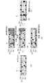
- FIG. 5 is a graph showing an example of an ultrasonic wave detection signal transmitted through an inspection area without damage
- FIG. 6 is a graph showing an example of an ultrasonic wave detection signal transmitted through the same inspection area having a damage.
- each vertical axis shows relative amplitude of an ultrasonic detection signal
- each horizontal axis shows time.
- the waveform of the ultrasonic wave passing through the damage changes. For this reason, the presence or absence of a defect such as damage can be detected by capturing the waveform change of the ultrasonic wave.
- the simulated waveform of the ultrasonic wave can be changed depending on the presence or absence of the simulated defect. That is, the simulated waveform of the ultrasonic wave affected by the simulated defect can be changed.
- the section through which the ultrasonic wave affected by the simulated defect propagates changes according to the position of the simulated defect. Therefore, the section in which the simulated waveform of the ultrasonic wave changes also varies in accordance with the position of the simulated defect.
- the optimal position of the ultrasonic sensor is a position at which the ultrasonic waveform changes sufficiently in the case where a defect occurs at an uncertain position in the target area A of ultrasonic inspection. Therefore, the optimum position of the ultrasonic sensor can be considered to be in a section in which the simulated waveform of the ultrasonic wave changes regardless of the position of the simulated defect.
- the recording of the section where the simulated waveform of the ultrasonic wave has changed is not only simple marking, that is, information not only indicating information indicating whether the simulated waveform of the ultrasonic wave has changed, but also recording with scoring corresponding to the amount of change of the simulated waveform. It can also be done.
- the recording of the section in which the simulated waveform has changed due to the influence of the simulated defect can be added among a plurality of simulations performed by changing the position of the simulated defect. This makes it possible to identify a section that is likely to change the ultrasonic simulated waveform regardless of the position of the simulated defect. Also, by converting the amount of change of the simulated waveform into points, it is possible to identify a section that is most likely to change the simulated waveform regardless of the position of the simulated defect.
- the simulated waveform in one of the sections changes whenever you change the position to generate a simulated defect, you can select the multiple sections as the most suitable section, no matter where the defect occurs.
- the positions of a plurality of ultrasonic sensors capable of detecting a waveform change of ultrasonic waves can be identified.
- an upper limit is set on the number of sections that can be selected as the arrangement position of ultrasonic sensors, and the number of sections exceeding the upper limit is selected. If this is the case, the number of ultrasonic transducer models 24 may be increased. As a specific example, assuming that the upper limit of the number of arrangement positions of ultrasonic sensors that can be selected corresponding to one ultrasonic transducer model 24 is one, plural sets of ultrasonic transducers and ultrasonic sensors The optimal position can be determined.
- the number of ultrasonic sensor models 24 is increased to create a new ultrasonic sensor model 24.
- the simulated waveform is most simulated waveform by converting the amount of change of the simulated waveform. It is possible to identify one section in which the change amount of becomes large.
- Whether or not the simulated waveform of the ultrasonic wave has changed under the influence of the simulated defect depends on the simulated waveform of the ultrasonic wave acquired by the simulation before introducing the simulated defect as the reference simulated waveform and after introducing the simulated defect It can be determined for each section by comparing with the simulated waveform of the ultrasonic wave acquired by simulation.
- the comparison between the simulated waveform after the introduction of the simulated defect and the reference simulated waveform before the introduction of the simulated defect directly compares the waveforms with each other, and also performs analysis processing such as Fourier analysis processing or wavelet analysis processing to compare, etc. It can be done by processing.
- analysis processing such as Fourier analysis processing or wavelet analysis processing to compare, etc. It can be done by processing.
- the simulated waveforms are directly compared, for example, the time when the amplitude of the ultrasonic detection signal is maximum can be compared. In this case, the time difference between peak times is the amount of change in the simulated waveform. Then, when the time difference between peak times exceeds the threshold value or exceeds the threshold value, it can be determined that the simulated waveform has changed.
- the simulated waveform of the ultrasonic wave and the reference simulated waveform are both waveforms obtained by simulation, so unlike the ultrasonic detection signal detected by the actual ultrasonic sensor, there is no noise. Therefore, signal processing to be executed on ultrasonic detection signals output from actual ultrasonic sensors, such as filtering for noise reduction and averaging, is unnecessary. Conversely, the process of extracting waveform features such as the envelope detection process may be performed on the simulated waveform of the ultrasonic wave and the reference simulated waveform as in the Fourier analysis process and the wavelet analysis process.
- the simulated waveform of ultrasonic waves may change in all sections. .
- the propagation condition of the simulated ultrasound in the simulation changes. Therefore, the simulated waveform of the ultrasonic wave changes in any section.
- the simulated waveform of the ultrasonic wave changes in any section.
- the influence of the simulated defect There is a possibility that the simulated waveform of the ultrasound did not change.
- the change in the simulated waveform due to the influence of the simulated defect can not be determined only by comparing the simulated waveform of the ultrasonic wave after the introduced simulation defect and the reference simulated waveform of the ultrasonic wave before the introduced simulated defect.
- the amount of change from the reference simulated waveform of the ultrasonic simulated waveform between the sections For example, a representative value such as an average value or an intermediate value of variation amounts of ultrasonic simulated waveforms in all sections or adjacent sections is determined, and the calculated representative value is compared with the variation amount of ultrasonic simulated waveforms in each section. can do. In this case, it is possible to cancel the change in the simulated waveform of the ultrasonic wave caused by factors other than the presence of the simulated defect. Therefore, it is possible to extract the change of the simulated waveform due to the influence of the simulated defect.
- the simulated waveform of the ultrasonic wave changes in all sections due to the difference between the simulation conditions before the introduction of the simulated defect and the simulation conditions after the introduction of the simulated defect other than the presence or absence of the simulated defect. Even if there is, it becomes possible to identify the section in which the simulated waveform has changed due to the influence of the simulated defect.
- the simulated waveform is affected by the simulated defect using the reference simulated waveform acquired by the simulation with different conditions other than the presence or absence of the simulated defect. It becomes possible to identify the changed section. Therefore, it is possible to eliminate the need to execute a large number of simulations for acquiring a reference simulated waveform corresponding to a large number of simulation conditions for each temperature and humidity. In other words, it is possible to execute the simulation after the introduction of the simulated defect under conditions such as temperature and humidity different from the conditions of the simulation before the introduction of the simulated defect for acquiring the reference simulated waveform of the simulated ultrasonic wave.
- the simulation conditions before the introduction of the simulated defect and the simulation conditions after the introduction of the simulated defect are the same except for the presence or absence of the simulated defect, as long as the simulated ultrasound is not affected by the simulated defect in any section.
- the simulated waveform does not change. Therefore, the comparison of the variation of the simulated waveform of the ultrasonic wave between the sections can be omitted.
- a process of creating a plurality of sections in the structure model 23 as illustrated in FIG. 4 and determining an optimum section as an arrangement position of an ultrasonic sensor by optimization calculation including simulation of an ultrasonic waveform is ultrasonic vibration. It can also be performed on the location of the child. That is, it is possible to fix the ultrasonic sensor model at a certain position, and to perform a simulation including the change of the section including the generation position of the simulated ultrasonic wave and the position change of the simulated defect.
- a section including the generation position of the simulated ultrasonic wave at the highest probability that the simulated waveform change due to the simulated defect occurs at the position where the ultrasonic sensor model is arranged is identified. be able to. Then, the inside of the identified section can be determined as the optimum arrangement position of the ultrasonic transducer. Therefore, it is also possible to optimize the position of both the ultrasound sensor and the ultrasound transducer.
- the ultrasonic inspection system When the ultrasonic inspection system is assembled by disposing at least one of the ultrasonic sensor and the ultrasonic transducer in the section thus determined, at least one of the ultrasonic transducer and the ultrasonic sensor Ultrasonic detection of a waveform change detectable in at least a signal processing system by a defect generated at an uncertain position in an ultrasonic inspection target area among a plurality of sections virtually provided on the surface of the target object An ultrasound inspection system will be fabricated that is located in the section that has the highest probability of occurring in the signal.
- the design information creation unit 6 of the design system 1 shown in FIG. 1 can be provided with desired functions according to the above-described optimization calculation algorithm.
- a section creation unit 6A that creates a plurality of sections in the FEM model for simulation simulating an object of ultrasonic inspection
- the design information creation unit 6 generates simulated defects, occurrence position, type, occurrence probability Defect condition introduction and change unit 6B introduced into FEM model by changing conditions such as, environmental condition change unit 6C to change environmental conditions such as temperature and humidity in simulation, number of ultrasonic sensors to be optimized, ultrasonic waves
- Optimization parameter setting / change unit 6D that sets and changes initial values of parameters such as sensor position, ultrasonic sensor direction, number of ultrasonic transducers, ultrasonic transducer position, ultrasonic transducer direction, etc.
- a simulation unit 6E that simulates the waveform of an ultrasonic wave for each given condition of simulated defects and environmental conditions by FEM analysis, simulated waves before and after introduction of the simulated defects
- the waveform change acquisition unit 6F acquires the change amount of each section, and identifies the change amount of the simulated waveform caused by the simulated defect for each section by comparing the change amount of the simulated waveform before and after the introduction of the simulated defect between the sections.
- Values of parameters to be optimized by selecting the optimum section as the position of the ultrasonic sensor and ultrasonic transducer based on the change amount of the simulated waveform caused by the waveform change comparison unit 6G and the simulated defect for each section
- a parameter optimum value determination unit 6H for determining
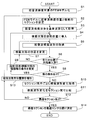
- FIG. 7 is a flow chart showing an example of the flow of optimization calculation executed by the design system 1 of the ultrasonic inspection system shown in FIG.
- the processing flow shown in FIG. 7 optimizes the position and number of ultrasonic sensors and the number of ultrasonic transducers, and changes not only the position of the simulated defect but also other conditions such as temperature and humidity.
- An example in the case of acquiring the position and the number of an optimal ultrasonic sensor and the position and the number of an ultrasonic transducer by simulating a simulated waveform of an ultrasonic wave as design information is shown.
- a model simulating an object of ultrasonic inspection is created by the modeling unit 5 of the design system 1.
- a structure model 23 for analysis can be created.
- the created FEM model is given from the modeling unit 5 to the design information creating unit 6.
- the design information generation unit 6 starts optimization calculation using the number of ultrasonic sensors, the position of ultrasonic sensors, and the number of ultrasonic transducers as parameters for generating design information of the ultrasonic inspection system. It is possible to
- step S2 a plurality of sections that are candidates for the placement position of the ultrasonic sensor are generated for the FEM model by the section creation unit 6A, as illustrated in FIG. 4A.
- the creation of the plurality of sections corresponds to the setting of the possible values of the arrangement position of the ultrasonic sensor, which is one of the parameters to be optimized.
- the optimization parameter setting / changing unit 6D determines the position at which the simulated ultrasound is generated in the FEM model.
- the generation position of the simulated ultrasound can be, for example, a position where the generation positions of the simulated ultrasound are arranged at equal intervals within a linear range that can be taken by the generated location of the simulated ultrasound.
- the generation position of the simulated ultrasonic wave is a central position that divides the linear range that can be obtained by the generation position of the simulated ultrasonic wave into two.
- the user may input information for specifying the generation position of the simulated ultrasonic wave to the optimization parameter setting / changing unit 6D by operating the input device 2 and manually determine the generation position of the simulated ultrasonic wave. Good.
- Such determination of the generation position of the simulated ultrasound corresponds to the setting of the number of ultrasonic transducers which is one of the parameters to be optimized and the setting position of the set number of ultrasonic transducers.
- step S3 simulation of ultrasonic inspection using the FEM model is executed in the simulation unit 6E. That is, analysis simulation of ultrasonic wave propagation behavior is executed for the FEM model that simulates the object of ultrasonic inspection.
- the waveform of the ultrasonic wave oscillated from the ultrasonic transducer to the target area of the ultrasonic inspection defined in the FEM model can be simulated on the FEM model.
- the waveform of the simulated ultrasound is given to the waveform change acquisition unit 6F as a reference simulation waveform for each section.
- step S4 the defect condition introduction / change unit 6B generates a simulated defect at an initial position in the target area of ultrasonic inspection on the FEM model.
- step S5 simulation of ultrasonic inspection using the FEM model is performed again in the simulation unit 6E. Thereby, the simulated waveform of the ultrasonic wave after generating the simulated defect can be acquired for each section.
- the acquired simulated waveform of the ultrasound for each section is given to the waveform change acquisition unit 6F.
- step S6 the defect condition introducing / changing unit 6B determines whether or not simulated defects have been generated at all positions where simulated defects should be generated. That is, the defect condition introduction / change unit 6B determines whether the position where the simulated defect is not generated remains in the inspection target area on the FEM model.
- step S6 If it is determined in step S6 that simulated defects are not generated at all positions, that is, if it is determined NO, the defect condition introduction / change unit 6B performs an inspection on the FEM model in step S7. The position of the simulated defect is changed in the target area. Then, again in step S5, the simulated waveform of the ultrasonic wave after changing the position and generating the simulated defect is acquired for each section.
- step S7 and the acquisition of the simulated waveform of the ultrasonic wave in step S5 are determined until it is determined in step S6 that the simulated defect has been generated at all positions, that is, YES. Until it is repeated. Thereby, the simulated waveform of the ultrasonic wave corresponding to the positions of all the simulated defects can be acquired for each section.
- step S8 it is determined in step S8 whether there is another simulation condition to be changed.
- simulation conditions to be changed environmental conditions such as temperature and humidity at the time of simulating an ultrasonic wave waveform in the FEM model can be mentioned in addition to the type of the simulated defect.
- the defect condition introducing / changing unit 6B determines whether or not there is another type of simulated defect to be generated.
- whether or not there is an environmental condition such as temperature or humidity to be changed is determined in the environmental condition changing unit 6C.
- step S8 If it is determined in step S8 that there is a simulation condition to be changed, that is, if it is determined YES, the simulation condition is changed in step S9. That is, if the simulation condition to be changed is the type of simulated defect, the defect condition introduction / change unit 6B changes the type of simulated defect. On the other hand, if the simulation conditions to be changed are environmental conditions such as temperature and humidity, the environmental condition changing unit 6C changes environmental conditions such as temperature and humidity.
- the simulated waveform of the ultrasonic wave corresponding to the position of all the simulated defects is acquired for every section by the process from step S4 to step S7 again.
- the simulation to be changed in the determination of step S8 is the change in the simulation conditions in step S9 and the acquisition of the simulated waveform of the ultrasonic wave corresponding to the positions of all the simulated defects in the process from step S4 to step S7.
- the process is repeated until it is determined that the condition does not exist, that is, NO.
- step S10 the waveform change acquisition unit 6F acquires, for each section and simulation condition, the amount of change in the simulated waveform of the ultrasonic wave before and after the occurrence of the simulated defect. If the simulation conditions other than the presence or absence of the simulated defect are not changed from the simulation conditions for acquiring the reference simulated waveform in step S3, the change amount of the simulated waveform of the ultrasonic wave occurs under the influence of the simulated defect. Amount of change.
- the variation amount of the simulated waveform of the ultrasonic wave is only the influence of the simulated defect. Is not necessarily the amount of change that has occurred. This is because the simulated waveform of the ultrasonic wave changes from the reference simulated waveform also by the influence of changing the simulation conditions.
- step S11 the waveform change comparison unit 6G compares the amounts of change in the simulated waveform for each section between the sections. Thereby, even if the simulation conditions other than the presence or absence of the simulated defect are changed from the simulation conditions for acquiring the reference simulated waveform, the simulated defect among the variation amounts of the simulated waveform of the ultrasonic wave in each section The changed amount of change can be extracted. Then, based on the amount of change in the extracted simulated waveform of the ultrasonic wave, it can be determined whether or not the simulated waveform of the ultrasonic wave has changed due to the simulated defect in each section.
- It can be determined, for example, by combining a plurality of signal analysis methods whether or not the simulated waveform of the ultrasonic wave in each section has been changed by the influence of the simulated defect.
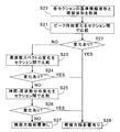
- FIG. 8 is a flow chart showing an example of an algorithm for determining whether or not the simulated waveform of the ultrasonic wave has changed due to a simulated defect in each section set for the FEM model as illustrated in FIG. 4 .
- step S20 the waveform change comparison unit 6G acquires a reference simulation waveform before the application of simulation defects in each section and a simulation waveform after the application of simulation defects.
- step S21 the waveform change comparison unit 6G calculates the difference between the peak time of the reference simulation waveform in each section and the peak time of the simulation waveform, that is, the variation of the peak time of the simulation waveform.
- the specification of the peak time of the simulated waveform in each section corresponds to the determination of the arrival time of each section of the simulated ultrasound.
- the waveform change comparison unit 6G determines the amount of change of the peak time of the simulated waveform in the section to be determined whether the simulated waveform has been changed by the influence of the simulated defect, and the peak time of the simulated waveform in the other section. Compare with the change in The sections to be compared may be all sections, or may be sections in the vicinity of the section to be determined in order to reduce the amount of data processing. The comparison process of the change amount of the peak time is sequentially executed with each section as a determination target.
- step S22 it is determined for each section whether the amount of change in peak time of the simulated waveform in the section to be determined has changed relative to the amount of change in peak time of the simulated waveform in the other sections. .
- the amount of change in peak time of the simulated waveform in the section to be judged is compared with that of the simulated waveform in the other sections by comparing the difference or ratio between the sections of the amount of change in peak time with the empirically determined threshold. It can be determined whether or not there is a change with respect to the amount of change in peak time.
- the waveform change comparison unit 6G simulates, in step S23, a section in which it is determined in step S22 that the change amount of peak time has not changed with respect to other sections, that is, a section determined as NO. Perform Fourier analysis of the waveform and the reference simulated waveform. Then, the frequency spectrum of the amplitude of the simulated waveform acquired by Fourier analysis of the simulated waveform and the reference frequency spectrum of the amplitude of the reference simulated waveform acquired by Fourier analysis of the reference simulated waveform are compared. Thereby, the amount of change of the frequency spectrum of the simulated waveform from the reference frequency spectrum is determined.
- the amount of change between frequency spectra can be expressed using a desired index, such as a difference in frequency at which a peak appears or a difference in peak value.
- the waveform change comparison unit 6G compares the amount of change in the frequency spectrum of the simulated waveform in the section determined as NO in the determination of step S22 with the amount of change in the frequency spectrum of the simulated waveform in the other sections.
- the sections to be compared may be all sections, or may be sections in the vicinity of the section to be determined in order to reduce the amount of data processing. In the case where all sections are to be compared, it is necessary that the simulated waveform and the reference simulated waveform in all the sections be targets of Fourier analysis.
- the comparison process of the variation of the frequency spectrum is sequentially executed with each section determined as NO in the determination of step S22 as a determination target.
- step S24 whether the amount of change in the frequency spectrum of the simulated waveform in the section determined as NO in the determination in step S22 has changed relative to the amount of change in the frequency spectrum of the simulated waveform in the other sections , Is determined for each section.
- the amount of change in the frequency spectrum of the simulated waveform in the section to be determined is compared with the other section by comparing the difference or ratio between sections of the index value representing the amount of change in the frequency spectrum with the empirically determined threshold. It can be determined whether or not it has changed with respect to the amount of change of the frequency spectrum of the simulated waveform in.
- the waveform change comparison unit 6G simulates in step S25 the section in which it is determined in step S24 that the change amount of the frequency spectrum is not changed with respect to other sections, that is, the section determined as NO. Perform wavelet analysis of waveform and reference simulated waveform. Then, the time-frequency distribution of the amplitude of the simulated waveform acquired by wavelet analysis of the simulated waveform and the time-frequency distribution of the amplitude of the reference simulated waveform acquired by wavelet analysis of the reference simulated waveform are compared. Thereby, the amount of change from the time-frequency distribution of the amplitude of the reference simulated waveform to the time-frequency distribution of the amplitude of the simulated waveform is determined. The amount of change between the amplitude and the time-frequency distribution can be expressed using a desired index, such as the frequency and time difference exhibiting peak and the difference between peak values.
- the waveform change comparison unit 6G changes the time-frequency distribution change amount of the amplitude of the simulated waveform in the section determined as NO in the determination of step S24, and changes the time-frequency distribution of the amplitude of the simulated waveform in the other sections.
- the sections to be compared may be all sections, or may be sections in the vicinity of the section to be determined in order to reduce the amount of data processing. In the case where all sections are to be compared, it is necessary to set the simulated waveform and the reference simulated waveform in all the sections as the target of wavelet analysis.
- the comparison process of the amount of change in time-frequency distribution of the amplitude is sequentially executed with each section determined as NO in the determination of step S24 as a determination target.
- step S26 the amount of change in the time-frequency distribution of the amplitude of the simulated waveform in the section determined as NO in the determination of step S24 corresponds to the amount of change in the time-frequency distribution of the amplitude of the simulated waveform in the other sections. It is determined for each section whether or not it has changed. For example, the time-frequency distribution of the amplitude of the simulated waveform in the section to be judged by comparing the difference or ratio between sections of the index value representing the amount of change of the amplitude time-frequency distribution with the threshold determined empirically It can be determined whether or not the change amount of has changed with respect to the change amount of the time-frequency distribution of the amplitude of the simulated waveform in the other section.
- step S26 For a section determined in step S26 that the amount of change in amplitude time-frequency distribution has not changed with respect to other sections, that is, a section determined NO, the effect of simulated defects in step S27. Thus, it is determined that the section in which the simulated waveform of the ultrasonic wave has not changed.
- the section in which the variation of the peak time of the simulated waveform is determined to change with respect to the other section that is, the section determined as YES
- the determination in step S24 In the section where it is determined that the amount of change in the frequency spectrum is changing relative to other sections, ie, the section where it is determined as YES and in the determination of step S26, the amount of change in the time-frequency distribution of the simulated waveform amplitude is For the sections determined to be changed with respect to the sections, that is, the sections determined to be YES, it is assumed that the section in which the simulated waveform of the ultrasonic wave has been changed under the influence of the simulated defect in step S28. It is judged.
- the amount of change in peak time of the simulated waveform, the amount of change in the frequency spectrum and the amount of change in the time-frequency distribution of the amplitude It can also be ranked according to which has changed detectably to the other sections. That is, as described above, it is possible to score the simulation waveform according to the amount of change from the reference simulation waveform.
- the waveform change comparison unit 6G can specify the amount of change from the reference simulation waveform of the simulation waveform of the ultrasonic wave due to the simulation defect for each section.
- peak time analysis, Fourier analysis, and wavelet analysis for a simulated waveform of ultrasonic waves are used in combination, it is determined whether the simulated waveform in each section changes under the influence of a simulated defect according to the degree Can.
- the parameter optimum value determination unit 6H determines whether there is an optimum section as an arrangement position of the ultrasonic sensor. Determine if As a specific example, if there is a section in which the simulated waveform has changed due to the effect of the simulated defect regardless of the position of the simulated defect, that section can be determined as the optimal arrangement position of the ultrasonic sensor.
- the section in which the change amount of the simulated waveform due to the simulated defect becomes largest by scoring It can be determined as the optimal placement position of
- the optimal placement position of the ultrasonic sensor always requires either section. It can be determined whether or not the simulated waveform will change due to the effect of the simulated defect. That is, if a plurality of sections are selected, it can be determined whether the simulated defects generated at all positions can always be detected as changes in the simulated waveform. And when selection of a plurality of sections which does not exceed the upper limit can cover simulated defects generated in all positions, a plurality of sections can be determined as the optimal arrangement position of the ultrasonic sensor.
- step S12 it is possible to determine in the determination of step S12 that there is no section optimum as the arrangement position of the ultrasonic sensor. Then, in step S13, the optimization parameter setting / changing unit 6D increases the generation position of the simulated ultrasound. Then, the processing from step S2 to step S11 is repeated again. For example, as described above, if the generation positions of the simulated ultrasonic waves are set at equal intervals in the linear range, the generation positions of the simulated ultrasonic waves are reset in step S2. In addition, the section may be changed according to the generation position of the simulated ultrasound.
- step S12 determines that there is an optimum section as an arrangement position of the ultrasonic sensor. If it is determined in step S12 that there is a section optimum as the arrangement position of the ultrasonic sensor, then in step S14, the parameter optimum value determination unit 6H is determined that the optimum position of the ultrasonic sensor is optimum. Decide in the section.
- the parameter optimum value determination unit 6H creates design information of an ultrasonic inspection system including the number of ultrasonic sensors, the position of ultrasonic sensors, the number of ultrasonic transducers, and the position of ultrasonic transducers.
- the design information of the created ultrasonic inspection system can be displayed on the display device 3 to notify the user. Further, the design information of the ultrasonic inspection system can be provided as a product of the information to the manufacturer and the manufacturing department of the ultrasonic inspection system.
- the ultrasound inspection system can be assembled based on the created design information.
- the ultrasound inspection system can also be assembled into an aircraft structure 10 as illustrated in FIGS. 2 and 3.
- the ultrasonic inspection system When mounting an ultrasonic inspection system on an aircraft structure, the ultrasonic inspection system will be part of the aircraft structure, and the design and manufacture of the ultrasonic inspection system will be part of the design and manufacture of the aircraft structure.
- the manufacturing method of the ultrasonic inspection system, the design system 1 of the ultrasonic inspection system, and the design program of the ultrasonic inspection system include the number of ultrasonic transducers and ultrasonic sensors that are components of the ultrasonic inspection system. And design information including position are created by optimization calculation including ultrasonic wave propagation analysis simulation.
- the manufacturing method of the ultrasonic inspection system the design system 1 of the ultrasonic inspection system, and the design program of the ultrasonic inspection system, the appropriate super for detecting the presence or absence of the defect by the ultrasonic inspection with the required accuracy.
- Design information of an acoustic transducer and an ultrasonic sensor can be created. That is, it is possible to perform ultrasonic inspection with higher accuracy with fewer components.
Landscapes
- Physics & Mathematics (AREA)
- Engineering & Computer Science (AREA)
- General Physics & Mathematics (AREA)
- Immunology (AREA)
- Biochemistry (AREA)
- Pathology (AREA)
- General Health & Medical Sciences (AREA)
- Analytical Chemistry (AREA)
- Health & Medical Sciences (AREA)
- Life Sciences & Earth Sciences (AREA)
- Chemical & Material Sciences (AREA)
- Manufacturing & Machinery (AREA)
- Signal Processing (AREA)
- Aviation & Aerospace Engineering (AREA)
- Transportation (AREA)
- Acoustics & Sound (AREA)
- Mathematical Physics (AREA)
- Spectroscopy & Molecular Physics (AREA)
- Algebra (AREA)
- Mathematical Analysis (AREA)
- Mathematical Optimization (AREA)
- Pure & Applied Mathematics (AREA)
- Investigating Or Analyzing Materials By The Use Of Ultrasonic Waves (AREA)
Abstract
Description
図1は本発明の実施形態に係る超音波検査システムの設計システムの機能ブロック図である。
次に、設計システム1による超音波検査システムの設計を含む超音波検査システムの製造方法及び超音波検査システムを設けた航空機構造体の製造方法について説明する。
以上のような、超音波検査システムの製造方法、超音波検査システムの設計システム1、超音波検査システムの設計プログラムは、超音波検査システムの構成要素となる超音波振動子及び超音波センサの数及び位置を含む設計情報を、超音波伝搬解析シミュレーションを含む最適化計算によって作成するようにしたものである。
以上、特定の実施形態について記載したが、記載された実施形態は一例に過ぎず、発明の範囲を限定するものではない。ここに記載された新規な方法及び装置は、様々な他の様式で具現化することができる。また、ここに記載された方法及び装置の様式において、発明の要旨から逸脱しない範囲で、種々の省略、置換及び変更を行うことができる。添付された請求の範囲及びその均等物は、発明の範囲及び要旨に包含されているものとして、そのような種々の様式及び変形例を含んでいる。
Claims (12)
- 少なくとも1つの超音波センサ及び少なくとも1つの超音波振動子を備えた超音波検査システムにより欠陥の有無を検出する超音波検査の対象を模擬したモデルを用いた前記超音波検査のシミュレーションを含む最適化計算であって、前記超音波センサの数、前記超音波センサの位置、前記超音波センサの向き、前記超音波振動子の数、前記超音波振動子の位置、前記超音波振動子の向き及び前記超音波振動子から発振される超音波の周波数の少なくとも1つをパラメータとする前記最適化計算を行うことによって、前記超音波センサの数、前記超音波センサの位置、前記超音波センサの向き、前記超音波振動子の数、前記超音波振動子の位置、前記超音波振動子の向き及び前記超音波振動子から発振される超音波の周波数を含む前記超音波検査システムの設計情報を作成するステップと、
前記設計情報に基づいて前記超音波検査システムを組立てるステップと、
を有する超音波検査システムの製造方法。 - 前記最適化計算は、
前記モデルに複数のセクションを作成するステップと、
前記モデル上における前記超音波検査の対象エリアに模擬欠陥を発生させるステップと、
前記超音波振動子から前記超音波検査の対象エリアに発振される超音波の波形を前記モデル上において模擬するステップと、
模擬された前記超音波の波形の前記模擬欠陥による変化量を前記セクションごとに特定するステップと、
特定された前記セクションごとの前記波形の変化量を前記セクション間において比較し、比較結果に基づいて前記超音波センサの最適位置をいずれかのセクション内に決定するステップと、
を有する請求項1記載の超音波検査システムの製造方法。 - 前記最適化計算は、
前記モデル上における前記超音波検査の対象エリアに模擬欠陥を発生させるステップと、
前記超音波振動子から前記超音波検査の対象エリアに発振される超音波の波形を前記モデル上において模擬するステップと、
前記モデル上の前記対象エリア内における前記模擬欠陥の位置、前記超音波の波形を模擬する際の温度、前記超音波の波形を模擬する際の湿度及び前記模擬欠陥の種類の少なくとも1つを含む模擬条件を変化させるステップと、
を有する請求項1又は2記載の超音波検査システムの製造方法。 - 前記モデルを複数の要素に分割し、前記超音波振動子から前記超音波検査の対象エリアに発振される超音波の波形を求める有限要素法による超音波伝搬解析を前記シミュレーションとして行い、前記シミュレーションにおいて、前記複数の要素のうちの特定の要素のヤング率の変更、特定の要素間における応力の伝達条件の変更及び特定の要素の形状変形の少なくとも1つによって、前記モデル上における前記超音波検査の対象エリアに模擬欠陥を発生させる請求項1乃至3のいずれか1項に記載の超音波検査システムの製造方法。
- 前記最適化計算によって、前記超音波検査の対象エリア内のどの位置で欠陥が生じても、少なくとも1つの前記超音波センサで検出される超音波検出信号に、前記欠陥によって波形変化を生じさせることができる前記超音波センサの数、前記超音波センサの位置、前記超音波振動子の数、前記超音波振動子の位置及び前記超音波振動子から発振される超音波の周波数を求める請求項1記載の超音波検査システムの製造方法。
- 前記超音波センサの位置及び前記超音波振動子の位置の少なくとも一方を前記パラメータとして前記最適化計算を行うことによって、前記超音波検査の対象エリア内の不確かな位置で生じる欠陥によって、前記超音波センサで検出される超音波検出信号に波形変化が生じる確率が最も高くなるときの前記パラメータの値を求める請求項1記載の超音波検査システムの製造方法。
- 少なくとも1つの超音波センサ及び少なくとも1つの超音波振動子を備えた超音波検査システムにより欠陥の有無を検出する超音波検査の対象を模擬したモデルを作成するモデル化部と、
前記超音波センサの数、前記超音波センサの位置、前記超音波センサの向き、前記超音波振動子の数、前記超音波振動子の位置、前記超音波振動子の向き及び前記超音波振動子から発振される超音波の周波数の少なくとも1つをパラメータとして前記モデルを用いた前記超音波検査のシミュレーションを含む最適化計算を行うことによって、前記超音波センサの数、前記超音波センサの位置、前記超音波センサの向き、前記超音波振動子の数、前記超音波振動子の位置、前記超音波振動子の向き及び前記超音波振動子から発振される超音波の周波数を含む前記超音波検査システムの設計情報を作成する設計情報作成部と、
を有する超音波検査システムの設計システム。 - コンピュータに、
少なくとも1つの超音波センサ及び少なくとも1つの超音波振動子を備えた超音波検査システムにより欠陥の有無を検出する超音波検査の対象を模擬したモデルを作成するステップ、及び
前記超音波センサの数、前記超音波センサの位置、前記超音波センサの向き、前記超音波振動子の数、前記超音波振動子の位置、前記超音波振動子の向き及び前記超音波振動子から発振される超音波の周波数の少なくとも1つをパラメータとして前記モデルを用いた前記超音波検査のシミュレーションを含む最適化計算を行うことによって、前記超音波センサの数、前記超音波センサの位置、前記超音波センサの向き、前記超音波振動子の数、前記超音波振動子の位置、前記超音波振動子の向き及び前記超音波振動子から発振される超音波の周波数を含む前記超音波検査システムの設計情報を作成するステップ、
を実行させる超音波検査システムの設計プログラム。 - 請求項1乃至6のいずれか1項に記載の製造方法で組立てられる前記超音波検査システムを航空機構造体に組付ける航空機構造体の製造方法。
- 超音波検査の対象エリアに向けて超音波を発振する超音波振動子と、
前記対象エリアを透過した前記超音波の透過波及び前記対象エリアで反射した前記超音波の反射波の少なくとも一方を検出して超音波検出信号を出力する超音波センサと、
前記超音波検出信号の基準波形からの波形変化を検出し、検出した前記波形変化に基づいて前記対象エリア内に欠陥が生じたか否かを検出する信号処理系と、
を備え、
前記超音波振動子及び前記超音波センサの少なくとも一方は、前記超音波検査の対象となる物体の表面に仮想的に設けられた複数のセクションのうち、前記対象エリア内の不確かな位置で生じる欠陥によって、前記信号処理系において検出可能な波形変化が前記超音波検出信号に生じる確率が最も高くなるセクション内に配置される超音波検査システム。 - 超音波検査の対象エリアであって、ウェブとフランジを有する前記対象エリアに向けて超音波を発振する少なくとも1つの超音波振動子と、
前記対象エリアを透過した前記超音波の透過波及び前記対象エリアで反射した前記超音波の反射波の少なくとも一方を検出して超音波検出信号を出力する少なくとも1つの超音波センサと、
前記超音波検出信号の基準波形からの波形変化を検出し、検出した前記波形変化に基づいて前記対象エリア内に欠陥が生じたか否かを検出する信号処理系と、
を備え、
前記超音波振動子及び前記超音波センサの数及び位置は、前記対象エリア内のどの位置で欠陥が生じても前記欠陥によって生じる前記超音波検出信号の波形変化を前記信号処理系で検出することができる数及び位置である超音波検査システム。 - 請求項10又は11記載の超音波検査システムを設けた航空機構造体。
Priority Applications (4)
| Application Number | Priority Date | Filing Date | Title |
|---|---|---|---|
| JP2019532369A JP6975236B2 (ja) | 2017-07-27 | 2018-04-03 | 超音波検査システムの製造方法 |
| EP18839450.6A EP3660500B1 (en) | 2017-07-27 | 2018-04-03 | Method of producing an ultrasonic inspection system |
| CN201880047439.6A CN110892261B (zh) | 2017-07-27 | 2018-04-03 | 超声波检查系统的制造方法 |
| US16/751,220 US11460445B2 (en) | 2017-07-27 | 2020-01-24 | Method of producing ultrasonic inspection system |
Applications Claiming Priority (2)
| Application Number | Priority Date | Filing Date | Title |
|---|---|---|---|
| JP2017145896 | 2017-07-27 | ||
| JP2017-145896 | 2017-07-27 |
Related Child Applications (1)
| Application Number | Title | Priority Date | Filing Date |
|---|---|---|---|
| US16/751,220 Continuation US11460445B2 (en) | 2017-07-27 | 2020-01-24 | Method of producing ultrasonic inspection system |
Publications (1)
| Publication Number | Publication Date |
|---|---|
| WO2019021538A1 true WO2019021538A1 (ja) | 2019-01-31 |
Family
ID=65039555
Family Applications (1)
| Application Number | Title | Priority Date | Filing Date |
|---|---|---|---|
| PCT/JP2018/014307 Ceased WO2019021538A1 (ja) | 2017-07-27 | 2018-04-03 | 超音波検査システムの製造方法 |
Country Status (5)
| Country | Link |
|---|---|
| US (1) | US11460445B2 (ja) |
| EP (1) | EP3660500B1 (ja) |
| JP (1) | JP6975236B2 (ja) |
| CN (1) | CN110892261B (ja) |
| WO (1) | WO2019021538A1 (ja) |
Cited By (2)
| Publication number | Priority date | Publication date | Assignee | Title |
|---|---|---|---|---|
| US11460445B2 (en) | 2017-07-27 | 2022-10-04 | Subaru Corporation | Method of producing ultrasonic inspection system |
| WO2024024309A1 (ja) * | 2022-07-28 | 2024-02-01 | コニカミノルタ株式会社 | 非破壊検査装置、非破壊検査方法、およびプログラム |
Families Citing this family (4)
| Publication number | Priority date | Publication date | Assignee | Title |
|---|---|---|---|---|
| US11783102B2 (en) * | 2019-04-30 | 2023-10-10 | BabySteps Orthopedics Inc. | Predictive modeling platform for serial casting to correct orthopedic deformities |
| US11644444B2 (en) * | 2021-02-23 | 2023-05-09 | The Boeing Company | Ultrasonic inspection margin check for design and manufacturing |
| CN113587959B (zh) * | 2021-07-28 | 2024-07-05 | 河北地质大学 | 一种地下管道损伤检测方法、装置及终端 |
| CN113740437B (zh) * | 2021-08-10 | 2023-06-16 | 西安交通大学 | 基于超声复合模型的含孔隙的涂层厚度及声速的测量方法 |
Citations (11)
| Publication number | Priority date | Publication date | Assignee | Title |
|---|---|---|---|---|
| US5031458A (en) * | 1987-05-22 | 1991-07-16 | The Boeing Company | Portable ultrasonic inspection probe for laminated structures |
| JPH04191653A (ja) * | 1990-11-26 | 1992-07-09 | Kansai Electric Power Co Inc:The | 超音波測定装置 |
| US20070000328A1 (en) * | 2005-01-06 | 2007-01-04 | Jonathan Buttram | Ultrasonic method for the accurate measurement of crack height in dissimilar metal welds using phased array |
| JP2011191230A (ja) | 2010-03-16 | 2011-09-29 | Fuji Heavy Ind Ltd | 損傷診断システム及び損傷診断方法 |
| JP2012112658A (ja) * | 2010-11-19 | 2012-06-14 | Mitsubishi Heavy Ind Ltd | 溶接部モデル作成装置、反射源位置推定装置、及び溶接部モデル作成方法 |
| JP2013088421A (ja) | 2011-10-16 | 2013-05-13 | Choonpa Zairyo Shindan Kenkyusho:Kk | 非破壊検査方法及び装置 |
| US20140172399A1 (en) * | 2011-08-30 | 2014-06-19 | Georgia Tech Research Corporation | Weld analysis using laser generated narrowband lamb waves |
| JP2014194379A (ja) | 2013-03-29 | 2014-10-09 | Fuji Heavy Ind Ltd | 損傷長測定システム及び損傷長測定方法 |
| JP2016038361A (ja) * | 2014-08-11 | 2016-03-22 | 新日鐵住金株式会社 | 欠陥検出装置、欠陥検出方法及びプログラム |
| JP2016517050A (ja) * | 2013-01-22 | 2016-06-09 | ゼネラル・エレクトリック・カンパニイ | 非破壊試験システムにおいてデータを分析するためのシステム及び方法 |
| JP2016107624A (ja) * | 2014-10-09 | 2016-06-20 | ザ・ボーイング・カンパニーThe Boeing Company | 複合材と金属との接合部を有する複合材構造体、及びその製造方法 |
Family Cites Families (11)
| Publication number | Priority date | Publication date | Assignee | Title |
|---|---|---|---|---|
| JP4617563B2 (ja) * | 2000-11-14 | 2011-01-26 | Jfeスチール株式会社 | 超音波探傷装置及び探傷方法 |
| JP3603805B2 (ja) * | 2001-03-29 | 2004-12-22 | Jfeスチール株式会社 | 内部欠陥検出方法 |
| JP4538629B2 (ja) * | 2004-04-27 | 2010-09-08 | 国立大学法人東北大学 | 閉じたき裂の定量評価法、及び閉じたき裂の定量評価装置 |
| US7249512B2 (en) * | 2005-01-24 | 2007-07-31 | The Boeing Company | Non-destructive stringer inspection apparatus and method |
| JP2009097942A (ja) * | 2007-10-16 | 2009-05-07 | Ihi Aerospace Co Ltd | 非接触式アレイ探触子とこれを用いた超音波探傷装置及び方法 |
| JP5672674B2 (ja) * | 2008-08-19 | 2015-02-18 | Jfeスチール株式会社 | 超音波映像化方法及び超音波映像化装置 |
| US9522512B2 (en) | 2010-08-17 | 2016-12-20 | The Boeing Company | Methods for making composite structures having composite-to-metal joints |
| EP2745107A1 (en) * | 2011-08-17 | 2014-06-25 | EMPA Eidgenössische Materialprüfungs- und Forschungsanstalt | Air coupled ultrasonic contactless method for non-destructive determination of defects in laminated structures |
| JP2014149156A (ja) * | 2013-01-31 | 2014-08-21 | Hitachi Ltd | 超音波検査方法及び装置 |
| JP6317708B2 (ja) * | 2015-06-12 | 2018-04-25 | 株式会社Subaru | 超音波探傷システム、超音波探傷方法及び航空機構造体 |
| CN110892261B (zh) | 2017-07-27 | 2023-05-30 | 株式会社斯巴鲁 | 超声波检查系统的制造方法 |
-
2018
- 2018-04-03 CN CN201880047439.6A patent/CN110892261B/zh active Active
- 2018-04-03 JP JP2019532369A patent/JP6975236B2/ja active Active
- 2018-04-03 WO PCT/JP2018/014307 patent/WO2019021538A1/ja not_active Ceased
- 2018-04-03 EP EP18839450.6A patent/EP3660500B1/en active Active
-
2020
- 2020-01-24 US US16/751,220 patent/US11460445B2/en active Active
Patent Citations (11)
| Publication number | Priority date | Publication date | Assignee | Title |
|---|---|---|---|---|
| US5031458A (en) * | 1987-05-22 | 1991-07-16 | The Boeing Company | Portable ultrasonic inspection probe for laminated structures |
| JPH04191653A (ja) * | 1990-11-26 | 1992-07-09 | Kansai Electric Power Co Inc:The | 超音波測定装置 |
| US20070000328A1 (en) * | 2005-01-06 | 2007-01-04 | Jonathan Buttram | Ultrasonic method for the accurate measurement of crack height in dissimilar metal welds using phased array |
| JP2011191230A (ja) | 2010-03-16 | 2011-09-29 | Fuji Heavy Ind Ltd | 損傷診断システム及び損傷診断方法 |
| JP2012112658A (ja) * | 2010-11-19 | 2012-06-14 | Mitsubishi Heavy Ind Ltd | 溶接部モデル作成装置、反射源位置推定装置、及び溶接部モデル作成方法 |
| US20140172399A1 (en) * | 2011-08-30 | 2014-06-19 | Georgia Tech Research Corporation | Weld analysis using laser generated narrowband lamb waves |
| JP2013088421A (ja) | 2011-10-16 | 2013-05-13 | Choonpa Zairyo Shindan Kenkyusho:Kk | 非破壊検査方法及び装置 |
| JP2016517050A (ja) * | 2013-01-22 | 2016-06-09 | ゼネラル・エレクトリック・カンパニイ | 非破壊試験システムにおいてデータを分析するためのシステム及び方法 |
| JP2014194379A (ja) | 2013-03-29 | 2014-10-09 | Fuji Heavy Ind Ltd | 損傷長測定システム及び損傷長測定方法 |
| JP2016038361A (ja) * | 2014-08-11 | 2016-03-22 | 新日鐵住金株式会社 | 欠陥検出装置、欠陥検出方法及びプログラム |
| JP2016107624A (ja) * | 2014-10-09 | 2016-06-20 | ザ・ボーイング・カンパニーThe Boeing Company | 複合材と金属との接合部を有する複合材構造体、及びその製造方法 |
Non-Patent Citations (1)
| Title |
|---|
| See also references of EP3660500A4 |
Cited By (2)
| Publication number | Priority date | Publication date | Assignee | Title |
|---|---|---|---|---|
| US11460445B2 (en) | 2017-07-27 | 2022-10-04 | Subaru Corporation | Method of producing ultrasonic inspection system |
| WO2024024309A1 (ja) * | 2022-07-28 | 2024-02-01 | コニカミノルタ株式会社 | 非破壊検査装置、非破壊検査方法、およびプログラム |
Also Published As
| Publication number | Publication date |
|---|---|
| JPWO2019021538A1 (ja) | 2020-03-19 |
| EP3660500A4 (en) | 2021-04-28 |
| US20200158691A1 (en) | 2020-05-21 |
| EP3660500B1 (en) | 2025-07-09 |
| JP6975236B2 (ja) | 2021-12-01 |
| EP3660500A1 (en) | 2020-06-03 |
| US11460445B2 (en) | 2022-10-04 |
| CN110892261B (zh) | 2023-05-30 |
| CN110892261A (zh) | 2020-03-17 |
| EP3660500C0 (en) | 2025-07-09 |
Similar Documents
| Publication | Publication Date | Title |
|---|---|---|
| JP6975236B2 (ja) | 超音波検査システムの製造方法 | |
| Sha et al. | Guided wavefield curvature imaging of invisible damage in composite structures | |
| Staszewski et al. | Health monitoring of aerospace composite structures–Active and passive approach | |
| Raghavan et al. | Guided-wave signal processing using chirplet matching pursuits and mode correlation for structural health monitoring | |
| US10724994B2 (en) | Structural health monitoring method and system | |
| US10180410B2 (en) | Ultrasonic test system, ultrasonic test method and aircraft structural object | |
| Sbarufatti et al. | Application of sensor technologies for local and distributed structural health monitoring | |
| JP6235508B2 (ja) | 超音波探傷システム、超音波探傷方法及び航空機部品の製造方法 | |
| JP2018146368A (ja) | 電流観測システム、電流観測方法及び航空機 | |
| Memmolo et al. | Damage localization in composite structures using a guided waves based multi-parameter approach | |
| Memmolo et al. | Structural health monitoring in composites based on probabilistic reconstruction techniques | |
| Liu et al. | Diagnosis of structural cracks using wavelet transform and neural networks | |
| Memmolo et al. | Model assisted probability of detection for a guided waves based SHM technique | |
| EP2269051B1 (en) | Imaging an anomaly using backscattered waves | |
| Wang et al. | Experimental and numerical validation of guided wave phased arrays integrated within standard data acquisition systems for structural health monitoring | |
| Boffa et al. | About the combination of high and low frequency methods for impact detection on aerospace components | |
| JP6506393B2 (ja) | 超音波検査システム、超音波検査方法及び航空機構造体 | |
| US12572801B2 (en) | Method for characterizing a part through non-destructive inspection | |
| Sellami et al. | Guided wave propagation in a realistic CFRP fuselage panel: Proof of concept for early-stage damage detection | |
| Rathod et al. | Machine learning enabled damage classification in composite laminated beams using mode conversion quantification | |
| Olson et al. | Computational Lamb wave model validation using 1D and 3D laser vibrometer measurements | |
| Jung et al. | Laser-based structural training algorithm for AE localization and damage accumulation visualization in a composite wing skin with various sub-structures | |
| Memmolo et al. | Multilevel structural health monitoring of real scale aerostructures using guided waves | |
| Li et al. | NDT&E International | |
| Bhandari et al. | Experimental Evaluation on Acoustic Emission Wave Propagation of Laminated Composites with Cutouts Using Auto Sensor Testing |
Legal Events
| Date | Code | Title | Description |
|---|---|---|---|
| 121 | Ep: the epo has been informed by wipo that ep was designated in this application |
Ref document number: 18839450 Country of ref document: EP Kind code of ref document: A1 |
|
| ENP | Entry into the national phase |
Ref document number: 2019532369 Country of ref document: JP Kind code of ref document: A |
|
| NENP | Non-entry into the national phase |
Ref country code: DE |
|
| WWE | Wipo information: entry into national phase |
Ref document number: 2018839450 Country of ref document: EP |
|
| ENP | Entry into the national phase |
Ref document number: 2018839450 Country of ref document: EP Effective date: 20200227 |
|
| WWG | Wipo information: grant in national office |
Ref document number: 2018839450 Country of ref document: EP |