WO2019022073A1 - 着脱装置、及び複数回注入装置 - Google Patents
着脱装置、及び複数回注入装置 Download PDFInfo
- Publication number
- WO2019022073A1 WO2019022073A1 PCT/JP2018/027700 JP2018027700W WO2019022073A1 WO 2019022073 A1 WO2019022073 A1 WO 2019022073A1 JP 2018027700 W JP2018027700 W JP 2018027700W WO 2019022073 A1 WO2019022073 A1 WO 2019022073A1
- Authority
- WO
- WIPO (PCT)
- Prior art keywords
- tube connector
- tube
- contrast agent
- saline
- injection device
- Prior art date
- Legal status (The legal status is an assumption and is not a legal conclusion. Google has not performed a legal analysis and makes no representation as to the accuracy of the status listed.)
- Ceased
Links
Images


Classifications
-
- A—HUMAN NECESSITIES
- A61—MEDICAL OR VETERINARY SCIENCE; HYGIENE
- A61M—DEVICES FOR INTRODUCING MEDIA INTO, OR ONTO, THE BODY; DEVICES FOR TRANSDUCING BODY MEDIA OR FOR TAKING MEDIA FROM THE BODY; DEVICES FOR PRODUCING OR ENDING SLEEP OR STUPOR
- A61M5/00—Devices for bringing media into the body in a subcutaneous, intra-vascular or intramuscular way; Accessories therefor, e.g. filling or cleaning devices, arm-rests
- A61M5/14—Infusion devices, e.g. infusing by gravity; Blood infusion; Accessories therefor
- A61M5/1407—Infusion of two or more substances
- A61M5/1408—Infusion of two or more substances in parallel, e.g. manifolds, sequencing valves
-
- A—HUMAN NECESSITIES
- A61—MEDICAL OR VETERINARY SCIENCE; HYGIENE
- A61M—DEVICES FOR INTRODUCING MEDIA INTO, OR ONTO, THE BODY; DEVICES FOR TRANSDUCING BODY MEDIA OR FOR TAKING MEDIA FROM THE BODY; DEVICES FOR PRODUCING OR ENDING SLEEP OR STUPOR
- A61M39/00—Tubes, tube connectors, tube couplings, valves, access sites or the like, specially adapted for medical use
- A61M39/10—Tube connectors; Tube couplings
- A61M39/105—Multi-channel connectors or couplings, e.g. for connecting multi-lumen tubes
-
- A—HUMAN NECESSITIES
- A61—MEDICAL OR VETERINARY SCIENCE; HYGIENE
- A61M—DEVICES FOR INTRODUCING MEDIA INTO, OR ONTO, THE BODY; DEVICES FOR TRANSDUCING BODY MEDIA OR FOR TAKING MEDIA FROM THE BODY; DEVICES FOR PRODUCING OR ENDING SLEEP OR STUPOR
- A61M39/00—Tubes, tube connectors, tube couplings, valves, access sites or the like, specially adapted for medical use
- A61M39/10—Tube connectors; Tube couplings
- A61M39/1011—Locking means for securing connection; Additional tamper safeties
-
- A—HUMAN NECESSITIES
- A61—MEDICAL OR VETERINARY SCIENCE; HYGIENE
- A61M—DEVICES FOR INTRODUCING MEDIA INTO, OR ONTO, THE BODY; DEVICES FOR TRANSDUCING BODY MEDIA OR FOR TAKING MEDIA FROM THE BODY; DEVICES FOR PRODUCING OR ENDING SLEEP OR STUPOR
- A61M39/00—Tubes, tube connectors, tube couplings, valves, access sites or the like, specially adapted for medical use
- A61M39/10—Tube connectors; Tube couplings
- A61M39/16—Tube connectors; Tube couplings having provision for disinfection or sterilisation
- A61M39/18—Methods or apparatus for making the connection under sterile conditions, i.e. sterile docking
-
- A—HUMAN NECESSITIES
- A61—MEDICAL OR VETERINARY SCIENCE; HYGIENE
- A61M—DEVICES FOR INTRODUCING MEDIA INTO, OR ONTO, THE BODY; DEVICES FOR TRANSDUCING BODY MEDIA OR FOR TAKING MEDIA FROM THE BODY; DEVICES FOR PRODUCING OR ENDING SLEEP OR STUPOR
- A61M39/00—Tubes, tube connectors, tube couplings, valves, access sites or the like, specially adapted for medical use
- A61M39/20—Closure caps or plugs for connectors or open ends of tubes
-
- A—HUMAN NECESSITIES
- A61—MEDICAL OR VETERINARY SCIENCE; HYGIENE
- A61M—DEVICES FOR INTRODUCING MEDIA INTO, OR ONTO, THE BODY; DEVICES FOR TRANSDUCING BODY MEDIA OR FOR TAKING MEDIA FROM THE BODY; DEVICES FOR PRODUCING OR ENDING SLEEP OR STUPOR
- A61M5/00—Devices for bringing media into the body in a subcutaneous, intra-vascular or intramuscular way; Accessories therefor, e.g. filling or cleaning devices, arm-rests
- A61M5/007—Devices for bringing media into the body in a subcutaneous, intra-vascular or intramuscular way; Accessories therefor, e.g. filling or cleaning devices, arm-rests for contrast media
-
- A—HUMAN NECESSITIES
- A61—MEDICAL OR VETERINARY SCIENCE; HYGIENE
- A61M—DEVICES FOR INTRODUCING MEDIA INTO, OR ONTO, THE BODY; DEVICES FOR TRANSDUCING BODY MEDIA OR FOR TAKING MEDIA FROM THE BODY; DEVICES FOR PRODUCING OR ENDING SLEEP OR STUPOR
- A61M5/00—Devices for bringing media into the body in a subcutaneous, intra-vascular or intramuscular way; Accessories therefor, e.g. filling or cleaning devices, arm-rests
- A61M5/14—Infusion devices, e.g. infusing by gravity; Blood infusion; Accessories therefor
- A61M5/1411—Drip chambers
-
- A—HUMAN NECESSITIES
- A61—MEDICAL OR VETERINARY SCIENCE; HYGIENE
- A61M—DEVICES FOR INTRODUCING MEDIA INTO, OR ONTO, THE BODY; DEVICES FOR TRANSDUCING BODY MEDIA OR FOR TAKING MEDIA FROM THE BODY; DEVICES FOR PRODUCING OR ENDING SLEEP OR STUPOR
- A61M5/00—Devices for bringing media into the body in a subcutaneous, intra-vascular or intramuscular way; Accessories therefor, e.g. filling or cleaning devices, arm-rests
- A61M5/14—Infusion devices, e.g. infusing by gravity; Blood infusion; Accessories therefor
- A61M5/142—Pressure infusion, e.g. using pumps
- A61M5/14212—Pumping with an aspiration and an expulsion action
- A61M5/14216—Reciprocating piston type
- A61M5/1422—Reciprocating piston type with double acting or multiple pistons
-
- A—HUMAN NECESSITIES
- A61—MEDICAL OR VETERINARY SCIENCE; HYGIENE
- A61M—DEVICES FOR INTRODUCING MEDIA INTO, OR ONTO, THE BODY; DEVICES FOR TRANSDUCING BODY MEDIA OR FOR TAKING MEDIA FROM THE BODY; DEVICES FOR PRODUCING OR ENDING SLEEP OR STUPOR
- A61M5/00—Devices for bringing media into the body in a subcutaneous, intra-vascular or intramuscular way; Accessories therefor, e.g. filling or cleaning devices, arm-rests
- A61M5/14—Infusion devices, e.g. infusing by gravity; Blood infusion; Accessories therefor
- A61M5/162—Needle sets, i.e. connections by puncture between reservoir and tube ; Connections between reservoir and tube
-
- A—HUMAN NECESSITIES
- A61—MEDICAL OR VETERINARY SCIENCE; HYGIENE
- A61M—DEVICES FOR INTRODUCING MEDIA INTO, OR ONTO, THE BODY; DEVICES FOR TRANSDUCING BODY MEDIA OR FOR TAKING MEDIA FROM THE BODY; DEVICES FOR PRODUCING OR ENDING SLEEP OR STUPOR
- A61M5/00—Devices for bringing media into the body in a subcutaneous, intra-vascular or intramuscular way; Accessories therefor, e.g. filling or cleaning devices, arm-rests
- A61M5/14—Infusion devices, e.g. infusing by gravity; Blood infusion; Accessories therefor
- A61M5/168—Means for controlling media flow to the body or for metering media to the body, e.g. drip meters, counters ; Monitoring media flow to the body
- A61M5/16804—Flow controllers
- A61M5/16827—Flow controllers controlling delivery of multiple fluids, e.g. sequencing, mixing or via separate flow-paths
-
- A—HUMAN NECESSITIES
- A61—MEDICAL OR VETERINARY SCIENCE; HYGIENE
- A61M—DEVICES FOR INTRODUCING MEDIA INTO, OR ONTO, THE BODY; DEVICES FOR TRANSDUCING BODY MEDIA OR FOR TAKING MEDIA FROM THE BODY; DEVICES FOR PRODUCING OR ENDING SLEEP OR STUPOR
- A61M5/00—Devices for bringing media into the body in a subcutaneous, intra-vascular or intramuscular way; Accessories therefor, e.g. filling or cleaning devices, arm-rests
- A61M5/14—Infusion devices, e.g. infusing by gravity; Blood infusion; Accessories therefor
- A61M5/168—Means for controlling media flow to the body or for metering media to the body, e.g. drip meters, counters ; Monitoring media flow to the body
- A61M5/16886—Means for controlling media flow to the body or for metering media to the body, e.g. drip meters, counters ; Monitoring media flow to the body for measuring fluid flow rate, i.e. flowmeters
-
- A—HUMAN NECESSITIES
- A61—MEDICAL OR VETERINARY SCIENCE; HYGIENE
- A61M—DEVICES FOR INTRODUCING MEDIA INTO, OR ONTO, THE BODY; DEVICES FOR TRANSDUCING BODY MEDIA OR FOR TAKING MEDIA FROM THE BODY; DEVICES FOR PRODUCING OR ENDING SLEEP OR STUPOR
- A61M5/00—Devices for bringing media into the body in a subcutaneous, intra-vascular or intramuscular way; Accessories therefor, e.g. filling or cleaning devices, arm-rests
- A61M5/14—Infusion devices, e.g. infusing by gravity; Blood infusion; Accessories therefor
- A61M2005/1401—Functional features
- A61M2005/1402—Priming
-
- A—HUMAN NECESSITIES
- A61—MEDICAL OR VETERINARY SCIENCE; HYGIENE
- A61M—DEVICES FOR INTRODUCING MEDIA INTO, OR ONTO, THE BODY; DEVICES FOR TRANSDUCING BODY MEDIA OR FOR TAKING MEDIA FROM THE BODY; DEVICES FOR PRODUCING OR ENDING SLEEP OR STUPOR
- A61M39/00—Tubes, tube connectors, tube couplings, valves, access sites or the like, specially adapted for medical use
- A61M39/10—Tube connectors; Tube couplings
- A61M2039/1016—Unlocking means providing a secure or comfortable disconnection
Definitions
- the present invention relates to a dispenser and to a multi-dosing apparatus with a dispenser.
- Patent Document 1 discloses a fluid dispensing system that fluidly connects a dispensing unit and a dispensing device (injection needle) that dispenses fluid to a subject.
- the fluid distribution system comprises a first pipe and a second pipe, the first pipe being connected to the second pipe and the dispensing unit, and the second pipe being connected to the dosing device and the first pipe.
- Ru the first tube portion comprises a one-way valve whereby fluid flows from the dispensing unit to the dispensing device but backflow from the dispensing device to the dispensing unit is prevented.
- the first pipe portion and the second pipe portion are fluidly connected to each other by a detachable connection device.
- connection device of the fluid distribution system comprises a first connection and a second connection which are removable from one another.
- the first connection includes, for example, a luer lock flange that fits into the duct of the second connection.
- the first connection portion and the second connection portion can be manually attached and detached.
- connection operation between the flow path on the side of the injection device to be reused and the flow path on the side of the subject to be discarded becomes complicated. Furthermore, if reverse blood is generated immediately after the injection of the drug solution, it may pass through the one-way valve to contaminate the reuse portion.
- the attachment-and-detachment device as an example of the present invention is the fixed part which fixes the 1st tube connector, the attaching part which holds the 2nd tube connector, and the attaching part which held the 2nd tube connector Is moved toward the first tube connector to connect the second tube connector to the first tube connector and move the second tube connector after the connection away from the first tube connector. And a moving unit that disconnects the second tube connector and the first tube connector.
- the 1st tube connector and the 2nd tube connector can be attached and detached automatically and mechanically, connection work of a channel is easy.
- the first tube connector and the second tube connector are physically separated immediately after the injection of the drug solution. Therefore, even if reverse blood is generated, it is possible to suppress contamination of the upstream side (the injection device side) of the attachment / detachment device.
- medical solution circuit It is a schematic perspective view which shows the state before the flow-path connection in 1st Embodiment of this invention. It is a schematic perspective view which shows the state after flow-path connection. It is a flowchart explaining the connection operation of a flow path. It is a schematic perspective view which shows the state before the flow-path connection in 2nd Embodiment of this invention. It is a flowchart explaining the connection operation of a flow path. It is a schematic top view which shows the state which strikes off a 1st cap. It is a schematic top view which shows the state which strikes off a 2nd cap. It is a schematic perspective view which shows the state before the flow-path connection in 3rd Embodiment of this invention. It is a schematic perspective view which shows the state before flow-path connection in 4th Embodiment of this invention.
- FIG. 1 is a schematic view of an injection system 500 capable of injecting a chemical solution a plurality of times, and shows a state in which flow paths are connected.
- the injection system 500 includes a multiple injection device 608 capable of injecting a chemical solution multiple times.
- the injection system 500 sucks the first medical solution for medical use such as a contrast agent and the second medical solution for medical use such as physiological saline into the syringe from the medical solution supply source and injects it into the subject who is the subject.
- the injection system 500 is connected to a contrast agent chamber 601 as a first chemical solution supply source and a saline chamber 602 as a second chemical solution supply source.
- the injection system 500 also includes a contrast agent line 501 and a saline line 502.
- the contrast agent line 501 and the saline line 502 each have, for example, a suction tube as a tube through which the drug solution flows.
- the line is a flow path through which liquid flows, and includes each member (for example, various tubes, T-shaped connectors, male connectors, female connectors, one-way valves, connection pipes, mixing devices, stopcocks, and rotators).
- the contrast agent line 501 has a tube, a first T-shaped connector T1, and a first one-way valve V1. Then, the contrast agent chamber 601 is connected to the mixing device S (for example, "SPIRAL FLOW” (registered trademark) manufactured by Nemoto Shurindo Co., Ltd.) through the tube and the first one-way valve V1 and the first T-shaped connector T1. , The tip of the contrast agent syringe 604 or a tube connected to the contrast agent syringe 604.
- the mixing device S for example, "SPIRAL FLOW” (registered trademark) manufactured by Nemoto Shurindo Co., Ltd.
- the saline line 502 includes a tube, a second T-shaped connector T2, and a second one-way valve V2.
- the saline chamber 602 is connected to the mixing device S and the tip of the saline syringe 605 or the saline syringe 605 via the tube and the second one-way valve V2 and the second T-shaped connector T2.
- Connected to the tube Connected to the tube. That is, the contrast agent line 501 and the saline line 502 are fluidly connected via the mixing device S.
- the contrast agent line 501 and the saline line 502 can be connected through a T-shaped connector.
- the contrast agent line 501 is connected to the contrast agent chamber 601 via a spike needle (not shown) with a drip chamber.
- the contrast agent chamber 601 is, for example, a bottle-shaped container filled with a contrast agent, and is used by being suspended by a hanger (not illustrated) (for example, a hanger attached to the multiple injection device 608) .
- the contrast agent flowing out of the contrast agent chamber 601 drips into the drip chamber of the spike needle with drip chamber and flows to the contrast agent line 501.
- the saline line 502 is connected to the saline chamber 602 via a spiked needle (not shown) with a drip chamber.
- the saline chamber 602 is, for example, a bag-like container filled with saline, and is used by being suspended by a hanger (not shown).
- the saline flowing out of the saline chamber 602 drips into the drip chamber of the spike needle with drip chamber and flows to the saline line 502.
- the first one-way valve V1, the second one-way valve V2, and the third one-way valve V3 are all pressure resistant one-way valves, which allow the flow in the downstream direction and block the flow in the upstream direction.
- a triangle mark attached to each one-way valve indicates the direction in which the chemical solution is shut off, and the tip of the triangle indicates the direction in which the chemical solution does not flow.
- the triangle attached to the first one-way valve V1 connected to the contrast agent line 501 means that the contrast agent does not flow toward the contrast agent chamber 601 (upstream direction).
- the first one-way valve V1 is attached to the first T-shaped connector T1.
- the first one-way valve V 1 allows flow in the direction toward the first tube 103 and blocks flow in the direction toward the contrast agent chamber 601.
- the second one-way valve V2 is attached to the second T-shaped connector T2.
- the second one-way valve V 2 allows flow in the direction toward the first tube 103 and blocks flow in the direction toward the saline chamber 602.
- the third one-way valve V3 is attached to the tube of the subject line 503.
- the third one-way valve V3 allows flow in the direction toward the subject and blocks flow in the direction toward the multiple injection device 608.
- the contrast agent when the contrast agent is aspirated toward the contrast agent syringe 604, the contrast agent flows from the contrast agent line 501 toward the contrast agent syringe 604. Then, when the contrast agent is discharged toward the subject line 503, the contrast agent does not backflow into the contrast agent chamber 601.
- the saline when the saline is aspirated toward the saline syringe 605, the saline flows from the saline line 502 toward the saline syringe 605. Then, when the saline is discharged toward the subject line 503, the saline does not backflow into the saline chamber 602.
- the multiple injection device 608 aspirates the drug solution from the contrast agent chamber 601 and the saline chamber 602, and injects the drug solution into the subject.
- a contrast agent syringe 604 as a first syringe and a saline syringe 605 as a second syringe are mounted on this multiple injection device 608, .
- the contrast agent syringe 604 and the saline syringe 605 are fixed to the syringe protection case with a plunger (not shown) attached.
- the syringe protection case is fixed to the injection device 608 multiple times by a syringe clamper.
- the multi-dose injection device 608 has a press (not shown) that engages with the plunger of the syringe. The multiple injection device 608 then moves the plunger forward (forward) or backward (retraction).
- the multiple injection device 608 has an operation unit 609.
- the operation unit 609 is provided with a forward button 609a, a reverse button 609b, and a stop button 609c.
- the operation unit 609 may be provided with operation buttons such as a start button and a priming button.
- a remote control device (not shown) such as a foot switch and a hand switch is connected to the multiple injection device 608 in a wired or wireless manner.
- the multiple injection device 608 is rotatably connected to a caster stand placed on the floor. In this way, the injection device 608 can be rotated a plurality of times between the attitude in which the front side of the injection device 608 is directed to the floor and the attitude in which the back side of the injection device 608 is directed to the floor.
- the multiple injection device 608 is connected to the caster stand so as to be pivotable in the left-right direction.
- the multi-dose injection device 608 can be connected to the ceiling hanging member so as to be suspended from the ceiling, or can be connected to a catheter table or a catheter rail.
- the multiple injection device 608 is connected to a controller (not shown) in a wired or wireless manner, and is connected to the controller, for example, via a head cable.
- the control device includes a touch panel and functions as a controller of the multiple injection device 608. Further, in the control device, data of an operation pattern (injection protocol) and data of a chemical solution are stored in advance.
- injection protocol injection protocol
- the operator operates the touch panel to control the test subject's physical data such as injection rate, injection amount, injection time and body weight, and drug solution data such as iodine amount and type of drug solution Enter in
- the control device calculates an optimal injection condition according to the input data and the data stored in advance. Then, the control device determines an injection protocol including the amount of the drug solution to be injected into the subject based on the calculated injection condition. Thereafter, in accordance with the operation of the operator, the multiple injection device 608 injects a drug solution according to the determined injection protocol. Alternatively, the controller can obtain the injection protocol and other data from an external storage medium.
- the multi-dose injection device 608 comprises a base 606 extending from the injection head portion 603 on which the syringe is mounted. At least a part of the attachment / detachment device 100, the contrast medium line 501, and the saline line 502 described below are accommodated in a groove formed in the base portion 606. That is, the first one-way valve V1, the first T-shaped connector T1, the second one-way valve V2, the second T-shaped connector T2, the mixing device S, and the mounting and demounting device 100 (the first tube 103 and the second tube 102) It is housed.
- the groove has a shape complementary to the corresponding member. As such, each member is positioned relative to the infusion device 608 multiple times by being placed in the groove.
- the multiple injection device 608 includes the attachment / detachment device 100 configured to be able to connect and separate the flow path on the multiple injection device 608 side and the flow path on the subject side.
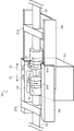
- the mounting and demounting device 100 includes a fixing portion 104 for fixing the first tube connector 105 and a holding portion 107 for holding the second tube connector 106.
- the attaching / detaching device 100 includes a moving unit 108 capable of moving the holding unit 107 holding the second tube connector 106 in the direction approaching the first tube connector 105 and in the direction away from the first tube connector 105.
- the moving unit 108 moves the holding unit 107 in a direction approaching the first tube connector 105 to connect the second tube connector 106 to the first tube connector 105.
- the moving unit 108 moves the second tube connector 106 after connection in a direction away from the first tube connector 105 to release the connection between the second tube connector 106 and the first tube connector 105.
- the first tube connector 105 is, for example, a female luer connector disposed at the tip of the first tube 103 connected to the mixing device S.
- the first tube connector 105 is inserted into a slot (not shown) provided in the fixing portion 104 and fixed to the mounting and demounting device 100.
- the second tube connector 106 is, for example, a male luer connector disposed at the tip of the second tube 102.
- the second tube connector 106 is held and held by a pair of fingers as the holding portion 107.
- the second tube 102 is connected to the third one-way valve V3 via a third tube connector 109.
- the third one-way valve V3 is attached to the subject line 503 of the injection system 500.
- a catheter (not shown) to be punctured by the subject is connected to the subject line 503. That is, the subject line 503 has a fourth tube connector 110 to which a catheter is connected.
- the moving unit 108 of the mounting and demounting device 100 is moved in a groove formed in the base portion 606 so as to be able to move forward and backward by a drive unit (not shown).
- a drive unit (not shown).
- the moving unit 108 and the fixing unit 104 fixed to the multiple injection device 608 form a nested structure. Therefore, as the moving unit 108 moves relative to the fixed unit 104, the end of the fixed unit 104 is received in the moving unit 108.
- the drive unit is, for example, a DC motor, and is connected to the drive shaft of the moving unit 108 via a gear train, a belt or a pulley.
- the pair of fingers as the holding portion 107 has a substantially roller-like shape.
- the pair of fingers rotate forward or reverse in conjunction with the movement of the moving unit 108. That is, the pair of fingers rotate forward while the moving unit 108 moves in the direction approaching the fixed unit 104. Therefore, the second tube connector 106 is rotated forward by the pair of fingers and screwed in contact with the first tube connector 105.
- the pair of fingers reverses while the moving portion 108 moves in the direction away from the fixed portion 104. Therefore, the second tube connector 106 is reversed by the pair of fingers and disengages from the first tube connector 105 to be spaced apart.
- the portion of the injection system 500 located downstream of the first tube 103 can be disposable.
- the first tube 103, the contrast agent line 501, and the saline line 502 can be reused. That is, after separating the second tube connector 106 from the first tube connector 105, the subject line 503 and the second tube 102 can be discarded. Then, the first tube 103, the contrast agent line 501, and the saline line 502 can be used again at the time of the next liquid injection.
- the holding units 107 are connected to the drive shaft of the moving unit 108 via a gear train, a belt, or a pulley.
- the holding unit 107 rotates in the forward or reverse direction in synchronization with the rotation of the drive shaft.
- a driving unit for the holding unit 107 may be provided separately from the driving unit of the moving unit 108.
- the holding unit 107 may be driven by a motor different from the motor of the moving unit 108.
- the mounting and demounting device 100 comprises a latch as a closing member for closing the flow path in the circuit.
- the drive source of the closing member is connected wirelessly or by wire to an external controller, and operates in response to a control signal from the controller to close the flow path.
- multiple injection devices 608 function as this controller.
- the attaching / detaching device 100 comprises a first closing member 101a closing the first tube 103 having the first tube connector 105, and a second closing member 101b closing the second tube 102 having the second tube connector 106. Is equipped.
- the first closing member 101 a is pivoted toward the first tube 103 by a drive source (not shown).
- the second closing member 101 b is pivoted toward the second tube 102 by a drive source (not shown).
- the first closing member 101 a and the second closing member 101 b are disposed in the moving portion 108. Therefore, both members move with the moving unit 108.
- the first closing member 101 a may be disposed on the fixed portion 104. Further, the first closing member 101 a and the second closing member 101 b may be rotated by the drive unit of the holding unit 107 (the drive unit of the moving unit 108).
- FIG. 2 shows the second tube connector 106 separated from the first tube connector 105.
- FIG. 3 shows the second tube connector 106 connected to the first tube connector 105.
- FIG. 4 is a flow chart showing the flow path connection operation.
- the operator Before injecting the drug solution, the operator connects the contrast agent line 501 to the contrast agent chamber 601 and connects the saline line 502 to the saline chamber 602. Then, the operator connects the tubes of the contrast agent line 501 and the saline line 502 to the multiple injection apparatus 608 (S101). Next, the operator connects the first tube 103 to the contrast agent line 501 and the saline line 502, and inserts the first tube connector 105 into the fixing portion 104 (S102). Furthermore, the operator connects the subject line 503 to the second tube 102, and inserts the second tube connector 106 into the holder 107 (S103).
- the first closing member 101a and the second closing member 101b can be pivoted toward the first tube 103 and the second tube 102, respectively, in the direction indicated by the arrow D1 in FIG. Then, the injection device 608 rotates the second closing member 101 b to crush the flow path in the second tube 102. That is, after the insertion into the fixing unit 104 and the holding unit 107 is completed, the multiple injection device 608 automatically closes the flow path (S104).
- the moving unit 108 is movable toward the fixed unit 104 in the direction indicated by the arrow D2 in FIG. 2. Then, the injection device 608 moves the moving unit 108 toward the fixed unit 104 a plurality of times. That is, the injection device 608 connects the flow paths automatically after closing the flow paths (S105). As a result, the second tube connector 106 held by the holding portion 107 moves toward the first tube connector 105 fixed to the fixing portion 104.
- the holding unit 107 While being moved by the moving unit 108, the holding unit 107 causes the second tube connector 106 to rotate in the direction indicated by the arrow D3 in FIG.
- the first tube connector 105 and the second tube connector 106 each have a thread and a thread groove. Therefore, when the second tube connector 106 contacts the first tube connector 105, both connectors are screwed together as the second tube connector 106 rotates. Thereby, the flow passage in the first tube 103 and the flow passage in the second tube 102 are in fluid communication.
- the first closing member 101a and the second closing member 101b can be pivoted away from the first tube 103 and the second tube 102, respectively, in the direction indicated by the arrow D4 in FIG. Then, the multiple injection device 608 rotates the second closing member 101 b to separate it from the second tube 102. As a result, the second tube 102 returns to its original shape by its own elastic force, and the flow passage inside thereof is opened. That is, after connecting the flow path, the multiple injection device 608 automatically opens the flow path (S106).
- priming Prior to the injection of the drug solution, priming for air removal is performed. Before priming, the operator fills the contrast agent syringe 604 with the contrast agent and fills the saline syringe 605 with the saline (S107). Specifically, the operator pushes the retraction button 609 b to retract the plungers of the contrast agent syringe 604 and the saline syringe 605. Thereby, the contrast agent is filled in the contrast agent syringe 604 via the contrast agent line 501. Further, physiological saline is filled in the physiological saline syringe 605 via the physiological saline line 502.
- priming manually by performing a predetermined operation (S108).
- priming may be performed automatically by depressing the priming button of the operation portion 609 of the multiple injection device 608.
- priming may be performed automatically by the injection device 608 a plurality of times at predetermined timing.
- the operator advances the plunger of the contrast agent syringe 604 and expels the contrast agent from the contrast agent syringe 604.
- the contrast agent fills the contrast agent line 501 as an example.
- the operator may fill the contrast agent line 501 to the subject line 503 with a contrast agent.
- the operator then advances the plunger of the saline syringe 605 to drain the saline from the saline syringe 605.
- the saline fills the saline line 502, the mixing device S, the first tube 103, the second tube 102, and the subject line 503 as an example.
- the operator may fill only the saline line 502 with saline.
- the entire chemical solution circuit is filled with the chemical solution, and the air is evacuated.
- the operator may simultaneously discharge the contrast agent and the saline solution for priming instead of discharging the contrast agent first.
- the operator may drain the physiological saline and drain the contrast agent for priming.
- the multiple injection device 608 After priming, the multiple injection device 608 automatically closes the flow path (S109). That is, the multiple injection device 608 pivots at least the second closing member 101 b to close the flow passage in the second tube 102. Furthermore, the multiple injection device 608 may also rotate the first closing member 101 a to close the flow passage in the first tube 103.
- the multiple injection device 608 After closing the flow path, the multiple injection device 608 automatically pressurizes the inside of the circuit (S110). That is, the multiple injection device 608 slightly advances the plunger of the contrast agent syringe 604 or the saline syringe 605. Thereafter, the operator punctures the subject with the catheter (S111).
- the internal pressure of the flow path on the upstream side of the mounting and demounting device 100 (the flow path in the first tube 103) is higher than that on the downstream side of the mounting and demounting device 100 (the flow path in the second tube 102) There is. Therefore, even if reverse blood is generated, the blood does not reach the reuse portion (the flow path on the upstream side of the attaching / detaching device 100). Furthermore, the flow path on the downstream side of the mounting and demounting device 100 is closed by the second closing member 101b. Therefore, even if reverse blood is generated, blood can be retained inside the waste portion (second tube 102) to prevent contamination of the reuse portion more reliably. Furthermore, since the third one-way valve V3 shuts off the flow in the direction toward the reuse part, it is possible to prevent contamination of the reuse part more reliably.
- the control device of the multiple injection device 608 has a touch panel, and when the amount of the drug solution and the injection protocol are determined, predetermined data or a graph is displayed on the touch panel. The operator confirms the display on the touch panel, and presses the enter button on the touch panel or the start button on the hand switch if the injection of the drug solution is started. Then, the control device transmits a chemical solution injection command to the injection device 608 a plurality of times.
- the multiple injection device 608 rotates the second closing member 101b to open the flow path (S112). At this time, the first closing member 101 a is in the flow passage open state separated from the first tube 103. However, if necessary, the multiple injection device 608 rotates the first closing member 101 a to open the flow path prior to the flow path release of the second tube 102.
- the multiple injection device 608 advances the plunger of the contrast agent syringe 604 to discharge the contrast agent from the contrast agent syringe 604 (S113).
- the first one-way valve V1 blocks the flow in the direction toward the contrast agent chamber 601. Therefore, the contrast agent flows into the mixing device S through the tube of the contrast agent line 501.
- the multiple injection device 608 advances the plunger of the saline syringe 605 to discharge the saline from the saline syringe 605.
- the second one-way valve V2 blocks the flow in the direction toward the saline chamber 602. Therefore, the saline flows into the mixing device S through the tube of the saline line 502. Thereby, the contrast agent and the saline flow into the mixing device S and are mixed in the mixing device S.
- a mixed drug solution of contrast agent and saline is injected to a predetermined imaging site via the subject line 503 and a catheter.
- the multiple injection device 608 advances the plunger of the saline syringe 605 to drain the saline from the saline syringe 605.
- saline is injected to a predetermined imaging site via the saline line 502 tube, the subject line 503, and the catheter. This flushes the contrast agent with saline.
- the multiple injection device 608 aspirates the contrast agent. That is, the multiple injection device 608 aspirates the contrast agent from the contrast agent chamber 601 toward the contrast agent syringe 604 by retracting the plunger of the contrast agent syringe 604. At this time, the first one-way valve V1 allows flow in the direction toward the contrast agent syringe 604. In addition, the multiple injection device 608 rotates the first closing member 101a and the second closing member 101b to close the flow path before suction of the contrast agent.
- the multiple injection device 608 sucks the saline solution. That is, the multiple injection device 608 aspirates physiological saline from the physiological saline chamber 602 toward the physiological saline syringe 605 by retracting the plunger of the physiological saline syringe 605. At this time, the second one-way valve V2 allows flow in the direction toward the saline syringe 605. In addition, the multiple injection device 608 rotates the first closing member 101a and the second closing member 101b to close the flow path before suctioning saline.
- the multiple injection device 608 pivots the first closing member 101a and the second closing member 101b to open the flow path. Subsequently, the multiple injection device 608 can discharge the aspirated contrast agent toward the subject line 503 by advancing the plunger of the contrast agent syringe 604. Similarly, the multiple injection device 608 can discharge the suctioned saline toward the subject line 503 by advancing the plunger of the saline syringe 605.
- the multiple injection device 608 automatically closes the flow path (S114). That is, the multiple injection device 608 rotates the second closing member 101 b to close the flow passage in the second tube 102. At this time, the first closing member 101 a is in the flow passage open state separated from the first tube 103.
- the moving unit 108 is movable in the direction away from the fixed unit 104 in the direction indicated by the arrow D5 in FIG. 3. Then, the multiple injection device 608 separates the moving unit 108 from the fixed unit 104. That is, after closing the flow path in the second tube 102, the multiple injection device 608 automatically disconnects the flow path (S115). As a result, the second tube connector 106 held by the holding portion 107 is separated from the first tube connector 105 fixed to the fixing portion 104.
- the holding unit 107 While being moved by the moving unit 108, the holding unit 107 reverses the second tube connector 106 in the direction indicated by the arrow D6 in FIG. Therefore, the second tube connector 106 is disengaged as the reverse rotation is performed, and the first tube connector 105 and the second tube connector 106 are unscrewed. Then, the connection between the flow passage in the first tube 103 and the flow passage in the second tube 102 is released. As a result, the flow path is separated, and even if reverse blood is generated, blood can not reach the reuse portion, so that contamination of the reuse portion can be prevented more reliably.
- the multiple injection device 608 determines whether the final injection has been completed (S116). If the final injection has been completed (YES in S116), that is, if the injection to the last subject is completed, the operation is completed. If the final injection has not been completed (NO in S116), that is, if there is a next injection to the subject, the process returns to S103 to continue the work. Specifically, the operator removes the used second tube 102 and the subject line 503. Next, the operator connects the subject line 503 to the second tube 102, and inserts the second tube connector 106 into the holder 107 (S103). Then, the next injection to the subject is performed.
- the multi-dose injection device 608 includes a sensor 530 disposed to face the first tube 103 having the first tube connector 105.
- the sensor 530 detects air inside the first tube 103 or detects the flow of a drug solution inside the first tube 103.
- the multi-dose injection device 608 may include a sensor 530 positioned to face the second tube 102 having the second tube connector 106.
- the sensor 530 sends a signal to the injector 608 multiple times when it detects the presence of a bubble.
- the multiple injection device 608 having received the signal performs at least one of stopping the injection of the chemical solution and notification (warning) of air detection.
- the sensor 530 transmits a signal to the injector 608 multiple times when the flow of the drug solution is not detected.
- the multiple injection device 608 having received the signal determines that the injection of the drug solution has been stopped. Then, the multiple injection device 608 closes the flow path in the first tube 103 and the second tube 102 in order to prevent blood contamination. Alternatively, the multiple injection device 608 moves the moving unit 108 to release the connection of the flow path.
- the sensor 530 is, for example, an ultrasonic sensor or an optical sensor (for example, an infrared sensor). Further, the sensor 530 may be disposed at a position facing the tube of the contrast agent line 501, the saline line 502, or the subject line 503. Further, the sensor 530 may be a temperature sensor that detects the temperature of the chemical solution. Since the bubble has a lower thermal conductivity than the chemical solution, the control device of the multiple injection device 608 can monitor the change in the detected temperature to determine the presence or absence of the bubble.
- the first tube connector 105 and the second tube connector 106 can be attached and detached automatically and mechanically, the connection work of the flow path is easy.
- the first tube connector 105 and the second tube connector 106 are physically separated immediately after the injection of the drug solution. Therefore, even if reverse blood is generated, it is possible to suppress contamination of the upstream side (the injection device side) of the attachment / detachment device 100.
- the syringe mounted on the multiple injection device 608 may be either a syringe filled with a drug solution or an empty syringe not filled with a drug solution. Then, the syringe filled with the drug solution is a prefilled syringe filled in advance with the drug solution, a syringe obtained by the operator filling the drug solution into an empty syringe with a suction device or a filler device, and an operator manually empty. These syringes are obtained by filling a syringe with a drug solution. Furthermore, two syringes mounted on the multiple injection device 608 may be filled with contrast agents of different concentrations. Further, at least one of the two syringes may be filled with a mixed drug solution of a contrast agent and saline.
- the attachment / detachment device 200 of the second embodiment removes at least one of the first cap 222 a attached to the first tube connector 105 and the second cap 222 b attached to the second tube connector 106.
- the removal member 221 is provided.
- the description of the second embodiment only the differences from the first embodiment will be described, and the description of the components described in the first embodiment will be omitted. Unless otherwise described, components with the same reference numeral perform substantially the same operation and function, and the operation and effect are also substantially the same.
- FIG. 5 is a schematic perspective view of the attachment / detachment device 200 in which the flow path is closed, and shows a state in which the second tube connector 106 is separated from the first tube connector 105.
- the mounting and demounting apparatus 200 includes a fixing portion 204 for fixing the first tube connector 105 and a holding portion 207 a for holding the first tube connector 105. Further, the mounting and demounting device 200 is provided with a holding portion 207 b for holding the second tube connector 106. Furthermore, the attaching / detaching device 200 is provided with a moving portion 208 capable of moving the holding portion 207 b holding the second tube connector 106 in the direction approaching the first tube connector 105 and in the direction away from the first tube connector 105.
- a first cap 222 a is attached to the first tube connector 105, and a second cap 222 b is attached to the second tube connector 106.
- the attachment / detachment apparatus 200 is provided with the removal member 221 which strikes off the 1st cap 222a and the 2nd cap 222b.
- the removing member 221 is pivoted in the direction indicated by the arrow D7 in FIG. 5 by a drive source (not shown). Further, the removing member 221 has a protruding portion 223 which protrudes outward.
- a recess extending in the width direction is formed.
- the recess has a U-shaped cross-sectional shape, but may have a V-shaped cross-sectional shape. Furthermore, the recess may extend in the longitudinal direction. In this case, both ends of the longitudinally extending recess collide with the first cap 222a and the second cap 222b, respectively.
- the mounting and demounting apparatus 200 includes a collection box 231 for collecting the first cap 222a and the second cap 222b. Openings are formed in the bottom of the fixed portion 204 and the moving portion 208 so as to communicate with the collection box 231. Therefore, the first cap 222 a and the second cap 222 b that are knocked off by the removal member 221 fall into the collection box 231. Further, the collection box 231 is removable from the mounting and demounting device 200. The operator can discard the first cap 222a and the second cap 222b in the removed collection box 231.
- the moving unit 208 is located inside the fixed unit 204. After the removal of the first cap 222a and the second cap 222b, the moving unit 208 moves in the direction indicated by the arrow D2 or the arrow D5 in FIG. As the moving unit 208 moves, the end of the moving unit 208 slides inside the fixed unit 204.
- the pair of fingers as the holding unit 207 b rotate forward while the moving unit 208 moves in the direction approaching the fixing unit 204.
- the second tube connector 106 is rotated forward by the pair of fingers and brought into contact with the first tube connector 105 and screwed.
- the pair of fingers reverses while the moving portion 208 moves in the direction away from the fixed portion 204.
- the second tube connector 106 is reversed by the pair of fingers and disengages from the first tube connector 105.
- the attaching / detaching device 200 includes a first closing member 201a closing the first tube 103 having the first tube connector 105, and a second closing member 201b closing the second tube 102 having the second tube connector 106. ing.
- the first closing member 201 a is disposed at the moving portion 208, and the second closing member 201 b is disposed at the fixed portion 204. Then, the first closing member 201a and the second closing member 201b respectively rotate in the direction indicated by the arrow D1 in FIG.
- FIG. 7 showing a state in which the first cap 222 a is knocked off
- FIG. 8 showing a state in which the second cap 222 b is knocked off
- the outline of the recovery box 231 which can not be seen from above is shown by a dotted line.
- the part which can not be visually recognized from upper direction among the 1st cap 222a and the 2nd cap 222b is shown in figure by the dotted line.
- the operator Before injecting the drug solution, the operator connects the contrast agent line 501 to the contrast agent chamber 601 and connects the saline line 502 to the saline chamber 602. Then, the operator connects the tubes of the contrast agent line 501 and the saline line 502 to the multiple injection apparatus 608 (S201). Next, the operator connects the first tube 103 to the contrast agent line 501 and the saline line 502, and inserts the first tube connector 105 into the fixing portion 204 (S202). Furthermore, the operator connects the subject line 503 to the second tube 102, and inserts the second tube connector 106 into the holder 207b (S203).
- the multiple injection device 608 rotates the first closing member 201a and the second closing member 201b to automatically close the flow path (S204). After closing the flow path, the multiple injection device 608 automatically removes the cap (S205). That is, the multiple injection device 608 rotates the removal member 221 to drop the first cap 222 a and the second cap 222 b into the collection box 231. More specifically, removal of the cap will be described with reference to FIGS. 7 and 8.
- the multiple injection device 608 rotates the removal member 221 to collide with the first cap 222a (FIG. 7).
- the first cap 222 a is detached from the first tube connector 105 by an impact due to a collision and falls into the collection box 231.
- the injection device 608 rotates the removal member 221 to move it to the original position (initial position).
- the multiple injection device 608 moves the moving unit 208 toward the fixed unit 204.
- the injection device 608 rotates the removal member 221 again to collide with the second cap 222b (FIG. 8).
- the second cap 222 b is separated from the second tube connector 106 by a collision impact and falls into the collection box 231.
- the injection device 608 rotates the removal member 221 to move it to the original position (initial position).
- the injection device 608 moves the moving unit 208 toward the fixed unit 204 and automatically connects the flow path (S206). Thereby, the flow passage in the first tube 103 and the flow passage in the second tube 102 are in fluid communication. Then, the multiple injection device 608 rotates the first closing member 201a and the second closing member 201b to automatically open the flow path (S207).
- the operator fills the contrast agent syringe 604 with the contrast agent, fills the saline syringe 605 with the saline (S208), and performs priming (S209).
- the multiple injection device 608 pivots the first closing member 201a and the second closing member 201b to automatically close the flow path (S210).
- the multiple injection device 608 automatically pressurizes the inside of the circuit (S211).
- the multi-infusion device 608 may close the flow path while pressurizing the circuit.
- the operator punctures the subject with the catheter (S212).
- the contrast agent and the saline can be filled at any timing after connecting the tubes of the contrast agent line 501 and the saline line 502 to the multiple injection device 608 (S201).
- the multiple injection device 608 Before injecting the chemical solution, the multiple injection device 608 rotates the second closing member 201b and the first closing member 201a to open the flow path (S213). Thereafter, the multiple injection device 608 ejects the contrast agent from the contrast agent syringe 604 (S214). When the contrast agent and the saline are simultaneously injected, the multiple injection device 608 also discharges the saline from the saline syringe 605. Thereby, the contrast agent and the saline flow into the mixing device S and are mixed in the mixing device S.
- the multiple injection device 608 rotates the first closing member 201a and the second closing member 201b to automatically close the flow path (S215). Then, the injection device 608 moves the moving unit 208 away from the fixing unit 204 and automatically disconnects the flow path (S216). Thereafter, the multiple injection device 608 determines whether or not the final injection has been completed (S217). If the final injection has been completed (YES in S217), that is, if the injection to the last subject is completed, the operation is completed. If the final injection has not been completed (NO in S217), that is, if there is a next injection to another subject, the process returns to S203 to continue the work.
- the first tube connector 105 and the second tube connector 106 can be attached and detached automatically and mechanically, the connection work of the flow path is easy.
- the first tube connector 105 and the second tube connector 106 are physically separated immediately after the injection of the drug solution. Therefore, even if reverse blood is generated, it is possible to suppress the contamination of the upstream side (the injection device side) of the attaching / detaching device 200.
- the first tube connector 105 and the second tube connector 106 are sealed by the first cap 222a and the second cap 222b, respectively. This can prevent the first tube connector 105 and the second tube connector 106 from being contaminated.
- the attachment / detachment device 300 rotates the first cap 222a to remove the first removal member 321a, and the second cap 222b rotates and removes the second removal member 321b.
- the third embodiment only the differences from the first and second embodiments will be described, and the description of the components described in the first and second embodiments will be omitted. Unless otherwise described, components with the same reference numeral perform substantially the same operation and function, and the operation and effect are also substantially the same.
- FIG. 9 is a schematic perspective view of the attachment / detachment device 300 in which the flow path is closed, and shows a state in which the second tube connector 106 is separated from the first tube connector 105.
- This attachment / detachment device 300 is provided with the fixing
- the mounting and demounting device 300 also includes a second removing member 321 b that also functions as a holding portion that holds the second tube connector 106.
- the attaching / detaching device 300 includes a moving unit 308 that can move the second removing member 321 b holding the second tube connector 106 in a direction toward the first tube connector 105 and in a direction away from the first tube connector 105. .
- a first cap 222 a is screwed into the first tube connector 105, and a second cap 222 b is screwed into the second tube connector 106.
- the attaching and detaching device 300 includes a first detaching member 321a that rotates the first cap 222a and a second detaching member 321b that rotates the second cap 222b.
- the first removing member 321a and the second removing member 321b are a pair of substantially roller-shaped members, respectively. Then, the first removing member 321a and the second removing member 321b rotate the first cap 222a and the second cap 222b in the directions shown by arrows D8 and D9 in FIG. 9, respectively, by a drive source (not shown).
- the mounting and demounting apparatus 300 includes a collection box 331 for collecting the first cap 222a and the second cap 222b. Openings are formed on the bottom surfaces of the fixed portion 304 and the moving portion 308 so as to communicate with the collection box 331. Therefore, the first cap 222 a and the second cap 222 b removed by the first removing member 321 a and the second removing member 321 b fall into the collection box 331.
- the collection box 331 is removable from the mounting and demounting device 300. The operator can discard the first cap 222a and the second cap 222b in the removed collection box 331.
- the collection box 331 of the third embodiment is smaller than that of the second embodiment because a slot for fixing the first tube connector 105 is formed on the bottom surface of the fixing portion 304.
- the multiple injection device 608 rotates the first removal member 321a to rotate the first cap 222a in the direction indicated by the arrow D8 in FIG.
- the first cap 222 a unscrewed by rotation is detached from the first tube connector 105 and falls into the collection box 331.
- the multiple injection device 608 rotates the second removal member 321b to rotate the second cap 222b in the direction indicated by arrow D9 in FIG.
- the second cap 222 b unscrewed by the rotation is detached from the second tube connector 106 and falls into the collection box 331.
- the multiple injection device 608 moves the moving unit 308 toward the fixing unit 304 to hold the second tube connector 106 on the second removing member 321 b.
- a rectangular slit 341 is formed so as not to inhibit the movement of the second removing member 321b. Therefore, the second removing member 321b moves in the slit 341 in the direction indicated by the arrow D5 or D2 in FIG. 9 as the moving unit 308 moves.
- Both end portions of the moving portion 308 are members having a substantially U-shaped cross-sectional shape, and cover the upper portion of the fixed portion 304.
- the moving unit 308 moves in the direction indicated by the arrow D2 or the arrow D5 in FIG.
- both ends of the fixed unit 304 are received in the moving unit 308.
- both ends of the fixed part 304 are exposed from the moving part 308.
- the second removing member 321 b rotates forward while the moving unit 308 moves in the direction approaching the fixing unit 304.
- the second tube connector 106 is rotated forward by the pair of fingers and brought into contact with the first tube connector 105 and screwed.
- the pair of fingers reverses while the moving part 308 moves in the direction away from the fixed part 304.
- the second tube connector 106 is reversed by the pair of fingers and disengages from the first tube connector 105.
- the attaching / detaching device 300 comprises a first closing member 201a closing the first tube 103 having the first tube connector 105, and a second closing member 201b closing the second tube 102 having the second tube connector 106.
- the first closing member 201 a is disposed at the fixed portion 304
- the second closing member 201 b is disposed at the moving portion 308. Then, the first closing member 201 a and the second closing member 201 b rotate respectively toward the first tube connector 105 and the second tube connector 106.
- the first tube connector 105 and the second tube connector 106 can be attached and detached automatically and mechanically, the connection work of the flow path is easy.
- the first tube connector 105 and the second tube connector 106 are physically separated immediately after the injection of the drug solution. Therefore, even if reverse blood is generated, it is possible to suppress contamination of the upstream side (the injection device side) of the attachment / detachment device 300.
- the first tube connector 105 and the second tube connector 106 are sealed by the first cap 222a and the second cap 222b, respectively. This can prevent the first tube connector 105 and the second tube connector 106 from being contaminated.
- the mounting and demounting apparatus 400 of the fourth embodiment includes a cartridge 440 that accommodates a plurality of second tube connectors 106.
- a cartridge 440 that accommodates a plurality of second tube connectors 106.
- the description of the fourth embodiment only the differences from the first and second embodiments will be described, and the description of the components described in the first and second embodiments will be omitted. Unless otherwise described, components with the same reference numeral perform substantially the same operation and function, and the operation and effect are also substantially the same.
- FIG. 10 is a schematic perspective view of the attachment / detachment device 400 in which the flow path is closed, and shows a state in which the second tube connector 106 is separated from the first tube connector 105.
- the attaching / detaching device 400 includes a fixing portion 404 which fixes the first tube connector 105, and a holding portion 207a which holds the first tube connector 105. Further, the mounting and demounting apparatus 400 is provided with a holding portion 207 b for holding the second tube connector 106.
- the attaching / detaching device 400 is provided with a moving portion 408 capable of moving the holding portion 207 b holding the second tube connector 106 in the direction approaching the first tube connector 105 and in the direction away from the first tube connector 105.
- the moving portion 408 has a substantially U-shaped cross-sectional shape, and is located inside the fixed portion 404.
- the moving unit 408 moves in the direction indicated by the arrow D2 or the arrow D5 in FIG. As the moving unit 408 moves, the end of the moving unit 408 slides inside the fixed unit 404.
- the pair of fingers as the holding unit 207 b rotates forward while the moving unit 408 moves in the direction approaching the fixing unit 404.
- the second tube connector 106 is rotated forward by the pair of fingers and brought into contact with the first tube connector 105 and screwed.
- the pair of fingers reverses while the moving portion 408 moves in the direction away from the fixed portion 404.
- the second tube connector 106 is reversed by the pair of fingers and disengages from the first tube connector 105.
- the mounting and demounting device 400 includes a first closing member 201 a that closes the first tube 103 having the first tube connector 105.
- the first closing member 201 a is rotatably disposed at the fixed portion 404.
- the mounting and demounting device 400 includes a cartridge 440 that can be mounted to and dismounted from the mounting and demounting device 400 while accommodating the plurality of second tube connectors 106 and the second tube 102. Slits are formed on the front and back surfaces of the housing of the cartridge 440.
- the operator attaches the cartridge 440 to the mounting and demounting apparatus 400 before injecting the drug solution. Then, when the injection of the drug solution is completed, the operator withdraws the used second tube connector 106 and the second tube 102 from the attaching / detaching device 400. Subsequently, the operator pushes down the second tube connector 106 and the second tube 102 in the cartridge 440 through the slit of the cartridge 440.
- the operator pushes the second tube connector 106 down to a position where it is held by the holding portion 207b.
- the second tube connector 106 and the second tube 102 are attached to the attaching / detaching device 400.
- the operator then resumes the infusion of the drug solution.
- the operator withdraws the used second tube connector 106 and second tube 102 from the attaching / detaching device 400 and replaces it with a new second tube connector 106 and second tube 102.
- the first tube connector 105 and the second tube connector 106 can be attached and detached automatically and mechanically, the connection work of the flow path is easy.
- the first tube connector 105 and the second tube connector 106 are physically separated immediately after the injection of the drug solution. Therefore, even if reverse blood is generated, it is possible to suppress contamination of the upstream side (the injection device side) of the attachment / detachment device 400.
- a cartridge 440 that accommodates the plurality of second tube connectors 106 and the second tubes 102 can be attached to the attaching / detaching device 400 according to the fourth embodiment. Thereby, it is possible to continuously inject the chemical solution.
- the syringe may be provided with data carriers such as RFID (Radio Frequency Identifier) and barcodes.
- the data carrier has recorded therein information on the filled drug solution.
- the injection device 608 can read information recorded from the data carrier and control the injection pressure of the drug solution.
- the multiple injection device 608 can be connected by wire or wirelessly to the imaging device. Then, at the time of injection of a chemical solution and at the time of imaging of an image, various data are transmitted and received between the imaging device and the multiple injection device 608. In this case, for example, imaging conditions may be set or displayed in the multiple injection device 608, and injection conditions may be set or displayed in the imaging device.
- an imaging device for example, an MRI (Magnetic Resonance Imaging) device, a CT (Computed Tomography) device, an angio imaging device, a PET (Positron Emission Tomography) device, a SPECT (Single Photon Emission Computed Tomography) device, a CT angio device
- MRI Magnetic Resonance Imaging
- CT Compputed Tomography
- angio imaging device a PET (Positron Emission Tomography) device
- SPECT Single Photon Emission Computed Tomography
- CT angio device for example, an MRI (Magnetic Resonance Imaging) device, a CT (Computed Tomography) device, an angio imaging device, a PET (Positron Emission Tomography) device, a SPECT (Single Photon Emission Computed Tomography) device, a CT angio device
- medical imaging devices such as an MR angiography device, an ultrasonic diagnostic device, and a blood vessel imaging device.
- the multiple injection apparatus 608 is an external storage apparatus such as RIS (Radiology Information System), PACS (Picture Archiving and Communication Systems), and HIS (Hospital Information System) via the network. Can also be sent and stored.
- RIS Radiology Information System
- PACS Physical Archiving and Communication Systems
- HIS Hospital Information System
- the first tube connector 105 may be a connector that automatically closes the flow path when it is not connected.
- the first tube connector 105 may be a type of connector connected by inserting a second tube connector 106 (male connector).
- a second tube connector 106 male connector
- this type of connector there are "Smart Site” manufactured by Nippon Becton Dickinson Co., Ltd. and "Sure Plug” (registered trademark) manufactured by Terumo Corporation. When this type of connector is used, the holding portion of the second tube connector 106 holds the second tube connector 106 without rotating.
Landscapes
- Health & Medical Sciences (AREA)
- Heart & Thoracic Surgery (AREA)
- General Health & Medical Sciences (AREA)
- Public Health (AREA)
- Engineering & Computer Science (AREA)
- Anesthesiology (AREA)
- Biomedical Technology (AREA)
- Hematology (AREA)
- Life Sciences & Earth Sciences (AREA)
- Animal Behavior & Ethology (AREA)
- Veterinary Medicine (AREA)
- Vascular Medicine (AREA)
- Pulmonology (AREA)
- Epidemiology (AREA)
- Physics & Mathematics (AREA)
- Fluid Mechanics (AREA)
- Infusion, Injection, And Reservoir Apparatuses (AREA)
- Loading And Unloading Of Fuel Tanks Or Ships (AREA)
- Quick-Acting Or Multi-Walled Pipe Joints (AREA)
- Automatic Assembly (AREA)
Abstract
自動的且つ機械的に第1チューブコネクター及び第2チューブコネクターを着脱する。着脱装置100は、第1チューブコネクター105を固定する固定部104と、第2チューブコネクター106を保持する保持部107と、第2チューブコネクター106を保持した保持部107を、第1チューブコネクター105に近づく方向に移動させて、第2チューブコネクター106を第1チューブコネクター105に接続すると共に、接続後の第2チューブコネクター106を第1チューブコネクター105から離れる方向に移動させて、第2チューブコネクター106及び第1チューブコネクター105の接続を解除する移動部とを備える。
Description
本発明は、着脱装置、及び着脱装置を備えた複数回注入装置(Multi-Dosing Apparatus)に関する。
特許文献1には、分配ユニットと、被験者に流体を分配する投薬装置(注射針)とを流体接続する流体分配システムが開示されている。この流体分配システムは、第1管部と第2管部とを備え、第1管部は第2管部及び分配ユニットに接続され、第2管部は投薬装置及び第1管部に接続される。また、第1管部は、一方向バルブを備え、それにより分配ユニットから投薬装置へは流体が流れるが、投薬装置から分配ユニットへの逆流は防がれる。これら第1管部及び第2管部は、互いに着脱自在な接続装置で流体接続される。
特許文献1の流体分配システムの一部は、再利用することができる。そのために、流体分配システムの接続装置は、互いに着脱自在な第1接続部及び第2接続部を備えている。この第1接続部は、例えば第2接続部のダクトに収まるルアーロックフランジを含んでいる。そして、第1接続部及び第2接続部は、手動で着脱することができる。
この流体分配システムでは、再利用される注入装置側の流路と廃棄される被験者側の流路との接続作業が煩雑になってしまう。さらに、薬液の注入直後に逆血が発生した場合には、一方向バルブを通過して再利用部分が汚染される可能性もある。
上記課題を解決するため、本発明の一例としての着脱装置は、第1チューブコネクターを固定する固定部と、第2チューブコネクターを保持する保持部と、前記第2チューブコネクターを保持した前記保持部を、前記第1チューブコネクターに近づく方向に移動させて、前記第2チューブコネクターを前記第1チューブコネクターに接続すると共に、接続後の前記第2チューブコネクターを前記第1チューブコネクターから離れる方向に移動させて、前記第2チューブコネクター及び前記第1チューブコネクターの接続を解除する移動部とを備えることを特徴とする。
これにより、自動的且つ機械的に第1チューブコネクター及び第2チューブコネクターを着脱できるので、流路の接続作業が容易である。また、薬液の注入直後に第1チューブコネクター及び第2チューブコネクターが物理的に離間される。そのため、仮に逆血が発生したとしても、着脱装置よりも上流側(注入装置側)が汚染されることを抑制できる。
本発明のさらなる特徴は、添付図面を参照して例示的に示した以下の実施形態の説明から明らかになる。
以下、本発明を実施するための例示的な実施形態を、図面を参照して詳細に説明する。ただし、以下の実施形態で説明する寸法、材料、形状及び構成要素の相対的な位置等は任意であり、本発明が適用される装置の構成又は様々な条件に応じて変更できる。また、特別な記載がない限り、本発明の範囲は、以下に具体的に記載された実施形態に限定されるものではない。なお、本明細書における注入装置の説明では、シリンジが搭載される側が前側に対応し、その反対側が後側に対応する。
[第1実施形態]
図1は、薬液を複数回注入可能な注入システム500の概略図であり、流路が接続されている状態を示している。この注入システム500は、薬液を複数回注入可能である複数回注入装置608を備えている。また、注入システム500は、造影剤等の医療用の第1薬液と生理食塩水等の医療用の第2薬液とを、それぞれ薬液供給源からシリンジ内に吸引すると共に、被写体である被験者に注入する際に用いられる。この注入システム500には、第1薬液供給源としての造影剤チャンバ601と、第2薬液供給源としての生理食塩水チャンバ602とが接続される。
図1は、薬液を複数回注入可能な注入システム500の概略図であり、流路が接続されている状態を示している。この注入システム500は、薬液を複数回注入可能である複数回注入装置608を備えている。また、注入システム500は、造影剤等の医療用の第1薬液と生理食塩水等の医療用の第2薬液とを、それぞれ薬液供給源からシリンジ内に吸引すると共に、被写体である被験者に注入する際に用いられる。この注入システム500には、第1薬液供給源としての造影剤チャンバ601と、第2薬液供給源としての生理食塩水チャンバ602とが接続される。
また、注入システム500は、造影剤ライン501と生理食塩水ライン502とを備えている。この造影剤ライン501及び生理食塩水ライン502は、薬液が流れるチューブとして、例えば吸引用チューブを有している。ここでラインとは、液体が流れる流路であり、各部材(例えば、各種チューブ、T字コネクター、オスコネクター、メスコネクター、一方弁、接続管、ミキシングデバイス、ストップコック、及びローテータ)を備える。
造影剤ライン501は、チューブと、第1T字コネクターT1と、第1一方弁V1とを有している。そして、造影剤チャンバ601は、チューブと、第1一方弁V1及び第1T字コネクターT1とを介して、ミキシングデバイスS(例えば、株式会社根本杏林堂製の「SPIRAL FLOW」(登録商標))と、造影剤シリンジ604の先端又は造影剤シリンジ604に接続されたチューブとに接続される。
同様に、生理食塩水ライン502は、チューブと、第2T字コネクターT2と、第2一方弁V2とを有している。そして、生理食塩水チャンバ602は、チューブと、第2一方弁V2及び第2T字コネクターT2とを介して、ミキシングデバイスSと、生理食塩水シリンジ605の先端又は生理食塩水シリンジ605に接続されたチューブとに接続される。つまり、造影剤ライン501と生理食塩水ライン502は、ミキシングデバイスSを介して流体接続されている。代替的に、T字コネクターを介して造影剤ライン501と生理食塩水ライン502を接続することもできる。
また、造影剤ライン501は、造影剤チャンバ601にドリップチャンバー付スパイク針(不図示)を介して接続される。この造影剤チャンバ601は、例えば、造影剤が充填されたボトル状の容器であり、不図示の吊り具(例えば、複数回注入装置608に取り付けられた吊り具)に吊り下げられて使用される。この造影剤チャンバ601から流れ出た造影剤は、ドリップチャンバー付スパイク針のドリップチャンバー内に滴下して、造影剤ライン501へと流れる。
同様に、生理食塩水ライン502は、生理食塩水チャンバ602にドリップチャンバー付スパイク針(不図示)を介して接続される。この生理食塩水チャンバ602は、例えば、生理食塩水が充填されたバッグ状の容器であり、不図示の吊り具に吊り下げられて使用される。この生理食塩水チャンバ602から流れ出た生理食塩水は、ドリップチャンバー付スパイク針のドリップチャンバー内に滴下して、生理食塩水ライン502へと流れる。
注入システム500において、第1一方弁V1、第2一方弁V2、及び第3一方弁V3は、いずれも耐圧一方弁であり、下流方向への流れを許容し上流方向への流れを遮断する。図1においては、各一方弁に付した三角マークによって薬液を遮断する方向を示しており、三角形の先端は薬液が流れない方向を指し示している。例えば、造影剤ライン501に接続された第1一方弁V1に付された三角形は、造影剤が造影剤チャンバ601(上流方向)に向かって流れないことを意味している。
具体的に、第1一方弁V1は、第1T字コネクターT1に取り付けられている。この第1一方弁V1は、第1チューブ103に向かう方向の流れを許容すると共に、造影剤チャンバ601に向かう方向の流れを遮断する。また、第2一方弁V2は、第2T字コネクターT2に取り付けられている。この第2一方弁V2は、第1チューブ103に向かう方向の流れを許容すると共に、生理食塩水チャンバ602に向かう方向の流れを遮断する。また、第3一方弁V3は、被験者ライン503のチューブに取り付けられている。この第3一方弁V3は、被験者に向かう方向の流れを許容すると共に、複数回注入装置608に向かう方向の流れを遮断する。
これらの一方弁により、造影剤が造影剤シリンジ604に向かって吸引された場合は、造影剤が造影剤ライン501から造影剤シリンジ604に向かって流れる。そして、造影剤が被験者ライン503に向かって排出された場合は、造影剤が造影剤チャンバ601に逆流しない。また、生理食塩水が生理食塩水シリンジ605に向かって吸引された場合は、生理食塩水が生理食塩水ライン502から生理食塩水シリンジ605に向かって流れる。そして、生理食塩水が被験者ライン503に向かって排出された場合は、生理食塩水が生理食塩水チャンバ602に逆流しない。
複数回注入装置608は、造影剤チャンバ601及び生理食塩水チャンバ602から薬液を吸引すると共に、被験者に薬液を注入する。この複数回注入装置608には、第1シリンジとしての造影剤シリンジ604と、第2シリンジとしての生理食塩水シリンジ605とが搭載される。造影剤シリンジ604及び生理食塩水シリンジ605は、プランジャー(不図示)が取り付けられた状態でシリンジ保護ケースに固定されている。そして、シリンジ保護ケースは、シリンジクランパーによって複数回注入装置608に固定されている。
複数回注入装置608は、シリンジのプランジャーと係合するプレッサー(不図示)を有している。そして、複数回注入装置608は、プランジャーを前方向(前進)又は後方向(後退)に移動する。また、複数回注入装置608は、操作部609を有している。この操作部609には、前進ボタン609a、後退ボタン609b及び停止ボタン609cが設けられている。また、操作部609には、スタートボタン、及びプライミングボタン等の操作ボタンが設けられていてもよい。さらに、複数回注入装置608には、フットスイッチ及びハンドスイッチ等の遠隔操作装置(不図示)が有線又は無線接続されている。
また、複数回注入装置608は、床面に置かれたキャスタースタンドに回動自在に接続される。これにより、複数回注入装置608の前側を床面に向ける姿勢と、複数回注入装置608の後側を床面に向ける姿勢とに複数回注入装置608を回動できる。好ましくは、複数回注入装置608は、左右方向に回動できるようにキャスタースタンドに接続される。代替的に、複数回注入装置608は、天井から天吊するように天吊部材に接続することもでき、又はカテテーブル若しくはカテレールに接続することもできる。
さらに、複数回注入装置608は、制御装置(不図示)に有線又は無線接続されており、例えば、ヘッドケーブルを介して制御装置に接続されている。この制御装置は、タッチパネルを備えると共に、複数回注入装置608のコントローラーとして機能する。また、制御装置には、動作パターン(注入プロトコル)のデータ及び薬液のデータが予め記憶されている。被験者に薬液を注入する場合、オペレーターは、タッチパネルを操作して、注入速度、注入量、注入時間及び体重等の被験者の身体的データと、ヨード量及び薬液の種類等の薬液データとを制御装置に入力する。
制御装置は、入力されたデータと予め記憶されているデータに応じて、最適な注入条件を算出する。そして、制御装置は、算出された注入条件に基づいて、被験者に注入する薬液の量を含む注入プロトコルを決定する。その後、オペレーターの操作に従い、複数回注入装置608は、決定された注入プロトコルに応じた薬液を注入する。代替的に、制御装置は、注入プロトコル及びその他データを、外部の記憶媒体から取得することもできる。
複数回注入装置608は、シリンジが搭載される注入ヘッド部603から延在する基部606を備えている。そして、以下に説明する着脱装置100と、造影剤ライン501と、生理食塩水ライン502とは、少なくともその一部が基部606に形成された溝内に収容されている。すなわち、第1一方弁V1、第1T字コネクターT1、第2一方弁V2、第2T字コネクターT2、ミキシングデバイスS、及び着脱装置100(第1チューブ103及び第2チューブ102)は、溝内に収容されている。この溝は、対応する部材と相補的な形状を有している。そのため、各部材は、溝内に配置することによって、複数回注入装置608に対して位置決めされる。
[着脱装置]
複数回注入装置608は、複数回注入装置608側の流路と被験者側の流路とを接続可能且つ分離可能に構成された着脱装置100を備えている。この着脱装置100は、第1チューブコネクター105を固定する固定部104と、第2チューブコネクター106を保持する保持部107とを備えている。さらに、着脱装置100は、第2チューブコネクター106を保持した保持部107を、第1チューブコネクター105に近づく方向及び第1チューブコネクター105から離れる方向に移動可能な移動部108を備えている。この移動部108は、保持部107を第1チューブコネクター105に近づく方向に移動させて、第2チューブコネクター106を第1チューブコネクター105に接続する。また、移動部108は、接続後の第2チューブコネクター106を第1チューブコネクター105から離れる方向に移動させて、第2チューブコネクター106及び第1チューブコネクター105の接続を解除する。
複数回注入装置608は、複数回注入装置608側の流路と被験者側の流路とを接続可能且つ分離可能に構成された着脱装置100を備えている。この着脱装置100は、第1チューブコネクター105を固定する固定部104と、第2チューブコネクター106を保持する保持部107とを備えている。さらに、着脱装置100は、第2チューブコネクター106を保持した保持部107を、第1チューブコネクター105に近づく方向及び第1チューブコネクター105から離れる方向に移動可能な移動部108を備えている。この移動部108は、保持部107を第1チューブコネクター105に近づく方向に移動させて、第2チューブコネクター106を第1チューブコネクター105に接続する。また、移動部108は、接続後の第2チューブコネクター106を第1チューブコネクター105から離れる方向に移動させて、第2チューブコネクター106及び第1チューブコネクター105の接続を解除する。
第1チューブコネクター105は、例えば、ミキシングデバイスSに接続された第1チューブ103の先端に配置されたメスルアーコネクタである。そして、第1チューブコネクター105は、固定部104に設けられたスロット(不図示)に挿入されて着脱装置100に対して固定されている。また、第2チューブコネクター106は、例えば、第2チューブ102の先端に配置されたオスルアーコネクタである。そして、第2チューブコネクター106は、保持部107としての一対のフィンガーに挟持され且つ保持されている。
第2チューブ102は、第3チューブコネクター109を介して、第3一方弁V3に接続されている。この第3一方弁V3は、注入システム500の被験者ライン503に取り付けられている。そして、被験者ライン503には、被験者に穿刺されるカテーテル(不図示)が接続される。すなわち、被験者ライン503は、カテーテルが接続される第4チューブコネクター110を有している。
着脱装置100の移動部108は、基部606に形成された溝内において、不図示の駆動部によって進退自在に移動される。具体的には、移動部108と、複数回注入装置608に対して固定された固定部104とが入れ子構造を構成している。そのため、移動部108が固定部104に対して移動するにつれて、固定部104の端部が移動部108内に受け入れられる。駆動部は、例えばDCモーターであり、ギアトレイン、ベルト又はプーリーを介して移動部108の駆動軸に接続されている。
保持部107としての一対のフィンガーは、略ローラ状の形状を有している。そして、一対のフィンガーは、移動部108の移動と連動して正転又は逆転する。すなわち、一対のフィンガーは、移動部108が固定部104に近づく方向に移動する間に正転する。そのため、第2チューブコネクター106は、一対のフィンガーによって正転し、第1チューブコネクター105と接触して螺合される。一方、一対のフィンガーは、移動部108が固定部104から離れる方向に移動する間に逆転する。そのため、第2チューブコネクター106は、一対のフィンガーによって逆転し、第1チューブコネクター105から係脱して離間する。
これにより注入システム500における、第1チューブ103よりも下流側に位置する部分は、使い捨て可能にできる。一方、第1チューブ103と、造影剤ライン501と、生理食塩水ライン502とは、再利用することができる。すなわち、第1チューブコネクター105から第2チューブコネクター106を分離した後、被験者ライン503及び第2チューブ102は廃棄できる。そして、第1チューブ103と、造影剤ライン501と、生理食塩水ライン502とは、次の薬液注入時に再度使用できる。
例えば、保持部107は、それぞれ移動部108の駆動軸に対してギアトレイン、ベルト又はプーリーを介して接続されている。これにより、保持部107は、駆動軸の回転と同期して正転又は逆転する。代替的に、移動部108の駆動部とは別に保持部107用の駆動部を設けてもよい。例えば、移動部108のモーターとは別のモーターで保持部107を駆動してもよい。
さらに、着脱装置100は、回路内の流路を閉鎖する閉鎖部材としてラッチを備えている。この閉鎖部材の駆動源は、外部のコントローラーに無線又は有線接続されており、コントローラーからの制御信号に応じて動作して流路を閉鎖する。例えば、複数回注入装置608がこのコントローラーとして機能する。
具体的に、着脱装置100は、第1チューブコネクター105を有する第1チューブ103を閉鎖する第1閉鎖部材101aと、第2チューブコネクター106を有する第2チューブ102を閉鎖する第2閉鎖部材101bとを備えている。第1閉鎖部材101aは、不図示の駆動源によって第1チューブ103に向かって回動される。また、第2閉鎖部材101bは、不図示の駆動源によって第2チューブ102に向かって回動される。
第1閉鎖部材101a及び第2閉鎖部材101bは、移動部108に配置されている。そのため、両部材は移動部108と共に移動する。代替的に、第1閉鎖部材101aは固定部104に配置してもよい。また、第1閉鎖部材101a及び第2閉鎖部材101bは、保持部107の駆動部(移動部108の駆動部)によって回動させてもよい。
[接続動作フロー]
流路の接続動作フローについて、図2から図4を参照して説明する。図2は、第2チューブコネクター106を第1チューブコネクター105から分離した状態を示している。図3は、第2チューブコネクター106を第1チューブコネクター105に接続した状態を示している。図4は、流路の接続動作を示すフローチャートである。
流路の接続動作フローについて、図2から図4を参照して説明する。図2は、第2チューブコネクター106を第1チューブコネクター105から分離した状態を示している。図3は、第2チューブコネクター106を第1チューブコネクター105に接続した状態を示している。図4は、流路の接続動作を示すフローチャートである。
薬液を注入する前に、オペレーターは、造影剤ライン501を造影剤チャンバ601に接続し、生理食塩水ライン502を生理食塩水チャンバ602に接続する。そして、オペレーターは、複数回注入装置608に造影剤ライン501及び生理食塩水ライン502のチューブを接続する(S101)。次に、オペレーターは、造影剤ライン501及び生理食塩水ライン502に第1チューブ103を接続し、第1チューブコネクター105を固定部104に挿入する(S102)。さらに、オペレーターは、被験者ライン503を第2チューブ102に接続して、第2チューブコネクター106を保持部107に挿入する(S103)。
図2の矢印D1に示す方向において、第1閉鎖部材101a及び第2閉鎖部材101bは、それぞれ第1チューブ103及び第2チューブ102に向かって回動可能である。そして、複数回注入装置608は、第2閉鎖部材101bを回動させて第2チューブ102内の流路を押し潰す。すなわち、複数回注入装置608は、固定部104及び保持部107への挿入が完了した後、自動的に流路を閉鎖する(S104)。
図2の矢印D2に示す方向において、移動部108は、固定部104に向かって移動可能である。そして、複数回注入装置608は、移動部108を固定部104に向かって移動させる。すなわち、複数回注入装置608は、流路を閉鎖した後に自動的に流路を接続する(S105)。これにより、保持部107に保持されている第2チューブコネクター106が、固定部104に固定された第1チューブコネクター105に向かって移動する。
移動部108によって移動される間に、図2の矢印D3に示す方向において、保持部107は第2チューブコネクター106を正転させる。第1チューブコネクター105及び第2チューブコネクター106は、それぞれねじ山及びねじ溝を備えている。そのため、第2チューブコネクター106が第1チューブコネクター105に接触すると、第2チューブコネクター106の回転に伴って両コネクターは螺合する。これにより、第1チューブ103内の流路と第2チューブ102内の流路とが流体連通する。
図3の矢印D4に示す方向において、第1閉鎖部材101a及び第2閉鎖部材101bは、それぞれ第1チューブ103及び第2チューブ102から離れるように回動可能である。そして、複数回注入装置608は、第2閉鎖部材101bを回動させて第2チューブ102から離間させる。これにより、第2チューブ102が自身の弾性力によって元の形状に復帰し、その内部の流路が開放される。すなわち、複数回注入装置608は、流路を接続した後に自動的に流路を開放する(S106)。
[プライミング]
薬液の注入前には、エア抜きを目的としたプライミングが行われる。プライミングを行う前に、オペレーターは、造影剤シリンジ604に造影剤を充填し、生理食塩水シリンジ605に生理食塩水を充填する(S107)。具体的には、オペレーターは後退ボタン609bを押して造影剤シリンジ604及び生理食塩水シリンジ605のプランジャーを後退させる。これにより、造影剤ライン501を介して造影剤シリンジ604内に造影剤が充填される。また、生理食塩水ライン502を介して生理食塩水シリンジ605内に生理食塩水が充填される。
薬液の注入前には、エア抜きを目的としたプライミングが行われる。プライミングを行う前に、オペレーターは、造影剤シリンジ604に造影剤を充填し、生理食塩水シリンジ605に生理食塩水を充填する(S107)。具体的には、オペレーターは後退ボタン609bを押して造影剤シリンジ604及び生理食塩水シリンジ605のプランジャーを後退させる。これにより、造影剤ライン501を介して造影剤シリンジ604内に造影剤が充填される。また、生理食塩水ライン502を介して生理食塩水シリンジ605内に生理食塩水が充填される。
次いで、オペレーターは、所定の操作を行うことにより手動でプライミングを行う(S108)。代替的に、プライミングは、複数回注入装置608の操作部609のプライミングボタンを押し下げることによって自動で行ってもよい。さらに、プライミングは、所定のタイミングで複数回注入装置608が自動で行ってもよい。
プライミングが開始されると、オペレーターは、造影剤シリンジ604のプランジャーを前進させ、造影剤シリンジ604から造影剤を排出する。これにより、造影剤が、一例として造影剤ライン501を満たす。代替的に、オペレーターは、造影剤ライン501から被験者ライン503までを造影剤で満たしてもよい。
次いで、オペレーターは、生理食塩水シリンジ605のプランジャーを前進させ、生理食塩水シリンジ605から生理食塩水を排出する。これにより、生理食塩水が、一例として生理食塩水ライン502、ミキシングデバイスS、第1チューブ103、第2チューブ102、及び被験者ライン503を満たす。代替的に、オペレーターは、生理食塩水ライン502のみを生理食塩水で満たしてもよい。
プライミングにより、薬液回路全体が薬液で満たされ、エアが抜かれた状態となる。なお、オペレーターは、造影剤を先に排出する代わりに、造影剤及び生理食塩水を同時に排出してプライミングを行ってもよい。また、オペレーターは、生理食塩水を排出した後に造影剤を排出してプライミングを行ってもよい。
プライミング後、複数回注入装置608は、自動的に流路を閉鎖する(S109)。すなわち、複数回注入装置608は、少なくとも第2閉鎖部材101bを回動させて第2チューブ102内の流路を閉鎖する。さらに、複数回注入装置608は、第1閉鎖部材101aも回動させて第1チューブ103内の流路を閉鎖してもよい。
流路を閉鎖した後に、複数回注入装置608は、自動的に回路内を加圧する(S110)。すなわち、複数回注入装置608は、造影剤シリンジ604又は生理食塩水シリンジ605のプランジャーをわずかに前進させる。その後、オペレーターは、カテーテルを被験者に穿刺する(S111)。
ここで、着脱装置100の上流側の流路(第1チューブ103内の流路)の内圧は、着脱装置100の下流側の流路(第2チューブ102内の流路)よりも高くなっている。そのため、仮に逆血が発生しても、血液は再利用部分(着脱装置100の上流側の流路)には到達しない。さらに、着脱装置100の下流側の流路は、第2閉鎖部材101bによって閉鎖されている。そのため、仮に逆血が発生しても、血液を廃棄部分(第2チューブ102)の内部に留めて、より確実に再利用部分の汚染を防止できる。さらに、第3一方弁V3が、再利用部分に向かう方向の流れを遮断するため、より確実に再利用部分の汚染を防止できる。
[薬液の注入]
複数回注入装置608の制御装置は、タッチパネルを有しており、薬液の量及び注入プロトコルが決定すると、所定のデータ又はグラフをタッチパネルに表示させる。オペレーターは、タッチパネルの表示を確認し、薬液の注入を開始するならばタッチパネルの決定ボタン又はハンドスイッチのスタートボタンを押す。すると、制御装置が複数回注入装置608に薬液の注入指令を送信する。
複数回注入装置608の制御装置は、タッチパネルを有しており、薬液の量及び注入プロトコルが決定すると、所定のデータ又はグラフをタッチパネルに表示させる。オペレーターは、タッチパネルの表示を確認し、薬液の注入を開始するならばタッチパネルの決定ボタン又はハンドスイッチのスタートボタンを押す。すると、制御装置が複数回注入装置608に薬液の注入指令を送信する。
薬液の注入前に、複数回注入装置608は、第2閉鎖部材101bを回動させて流路を開放する(S112)。このとき、第1閉鎖部材101aは第1チューブ103から離間した流路開放状態にある。ただし、必要であれば複数回注入装置608は、第2チューブ102の流路解放に先だって、第1閉鎖部材101aを回動させて流路を開放する。
その後、複数回注入装置608は、造影剤シリンジ604のプランジャーを前進させて、造影剤シリンジ604から造影剤を排出する(S113)。このとき、第1一方弁V1は、造影剤チャンバ601に向かう方向の流れを遮断する。そのため、造影剤は、造影剤ライン501のチューブを介してミキシングデバイスSに流入する。
さらに、造影剤と生理食塩水とを同時に注入する場合、複数回注入装置608は、生理食塩水シリンジ605のプランジャーを前進させて、生理食塩水シリンジ605から生理食塩水を排出する。このとき、第2一方弁V2は、生理食塩水チャンバ602に向かう方向の流れを遮断する。そのため、生理食塩水は、生理食塩水ライン502のチューブを介してミキシングデバイスSに流入する。これにより、造影剤及び生理食塩水は、ミキシングデバイスSに流入し、ミキシングデバイスS内において混合される。
造影剤及び生理食塩水の混合薬液は、被験者ライン503及びカテーテルを介して所定の撮像部位へと注入される。造影剤の注入が完了した後、複数回注入装置608は、生理食塩水シリンジ605のプランジャーを前進させて、生理食塩水シリンジ605から生理食塩水を排出する。そして、生理食塩水は、生理食塩水ライン502のチューブ、被験者ライン503、及びカテーテルを介して所定の撮像部位へと注入される。これにより、生理食塩水による造影剤のフラッシュが行われる。
造影剤シリンジ604内の造影剤の量が所定量よりも少なくなった場合、複数回注入装置608は造影剤の吸引を行う。すなわち、複数回注入装置608は、造影剤シリンジ604のプランジャーを後退させることで、造影剤チャンバ601から造影剤シリンジ604に向かって造影剤を吸引する。このとき、第1一方弁V1は、造影剤シリンジ604に向かう方向の流れを許容する。また、複数回注入装置608は、造影剤の吸引前に、第1閉鎖部材101a及び第2閉鎖部材101bを回動させて流路を閉鎖する。
生理食塩水シリンジ605内の生理食塩水の量が所定量よりも少なくなった場合、複数回注入装置608は生理食塩水の吸引を行う。すなわち、複数回注入装置608は、生理食塩水シリンジ605のプランジャーを後退させることで、生理食塩水チャンバ602から生理食塩水シリンジ605に向かって生理食塩水を吸引する。このとき、第2一方弁V2は、生理食塩水シリンジ605に向かう方向の流れを許容する。また、複数回注入装置608は、生理食塩水の吸引前に、第1閉鎖部材101a及び第2閉鎖部材101bを回動させて流路を閉鎖する。
吸引後、複数回注入装置608は、第1閉鎖部材101a及び第2閉鎖部材101bを回動させて流路を開放する。続いて、複数回注入装置608は、造影剤シリンジ604のプランジャーを前進させることで、吸引した造影剤を被験者ライン503に向かって排出することができる。同様に、複数回注入装置608は、生理食塩水シリンジ605のプランジャーを前進させることで、吸引した生理食塩水を被験者ライン503に向かって排出することができる。
薬液の注入が完了すると、複数回注入装置608は、自動的に流路を閉鎖する(S114)。すなわち、複数回注入装置608は、第2閉鎖部材101bを回動させて第2チューブ102内の流路を閉鎖する。このとき、第1閉鎖部材101aは第1チューブ103から離間した流路開放状態にある。
図3の矢印D5に示す方向において、移動部108は、固定部104から離れる方向に移動可能である。そして、複数回注入装置608は、移動部108を固定部104から離間させる。すなわち、複数回注入装置608は、第2チューブ102内の流路を閉鎖した後に自動的に流路の接続を解除する(S115)。これにより、保持部107に保持されている第2チューブコネクター106が、固定部104に固定された第1チューブコネクター105から離間する。
移動部108によって移動される間に、図3の矢印D6に示す方向において、保持部107は第2チューブコネクター106を逆転させる。そのため、逆転に伴って第2チューブコネクター106が係脱し、第1チューブコネクター105及び第2チューブコネクター106の螺合が解除される。そして、第1チューブ103内の流路と第2チューブ102内の流路との接続が解除される。これにより、流路が分離され、仮に逆血が発生しても血液が再利用部分には到達し得ないため、より確実に再利用部分の汚染を防止できる。
その後、複数回注入装置608は、最終注入が完了したか否かを判断する(S116)。最終注入が完了している場合(S116でYES)、すなわち最後の被験者への注入が完了している場合には、作業が終了する。最終注入が完了していない場合(S116でNO)、すなわち被験者への次の注入がある場合には、S103に戻って作業を継続する。
具体的に、オペレーターは、使用済みの第2チューブ102及び被験者ライン503を取り外す。次に、オペレーターは、被験者ライン503を第2チューブ102に接続して、第2チューブコネクター106を保持部107に挿入する(S103)。そして、被験者への次の注入が行われる。
具体的に、オペレーターは、使用済みの第2チューブ102及び被験者ライン503を取り外す。次に、オペレーターは、被験者ライン503を第2チューブ102に接続して、第2チューブコネクター106を保持部107に挿入する(S103)。そして、被験者への次の注入が行われる。
[センサー]
図1に示すように、複数回注入装置608は、第1チューブコネクター105を有する第1チューブ103に対向するように配置されたセンサー530を備えている。このセンサー530は、第1チューブ103の内部のエアを検知するか、又は第1チューブ103の内部の薬液の流れを検知する。さらに、複数回注入装置608は、第2チューブコネクター106を有する第2チューブ102に対向するように配置されたセンサー530を備えていてもよい。
図1に示すように、複数回注入装置608は、第1チューブコネクター105を有する第1チューブ103に対向するように配置されたセンサー530を備えている。このセンサー530は、第1チューブ103の内部のエアを検知するか、又は第1チューブ103の内部の薬液の流れを検知する。さらに、複数回注入装置608は、第2チューブコネクター106を有する第2チューブ102に対向するように配置されたセンサー530を備えていてもよい。
センサー530は、気泡の存在を検出した場合に、複数回注入装置608に信号を送信する。信号を受信した複数回注入装置608は、薬液の注入の停止及びエア検出の報知(警告)の少なくとも一方を行う。または、センサー530は、薬液の流れが検知されなくなった場合に、複数回注入装置608に信号を送信する。信号を受信した複数回注入装置608は、薬液の注入が停止されたと判断する。そして、複数回注入装置608は、逆血による汚染を防止するために、第1チューブ103及び第2チューブ102内の流路を閉鎖する。または、複数回注入装置608は、移動部108を移動させて流路の接続を解除する。
このセンサー530は、例えば、超音波式センサー又は光学式センサー(例えば赤外線式センサー)である。さらに、センサー530は、造影剤ライン501、生理食塩水ライン502、又は被験者ライン503のチューブに対向する位置に配置しても良い。また、センサー530は、薬液の温度を検知する温度センサーであってもよい。気泡は薬液よりも熱伝導率が低いため、複数回注入装置608の制御装置は、検知された温度の変化を監視して気泡の有無を判断できる。
以上説明した第1実施形態に係る注入システム500によれば、自動的且つ機械的に第1チューブコネクター105及び第2チューブコネクター106を着脱できるので、流路の接続作業が容易である。また、薬液の注入直後に第1チューブコネクター105及び第2チューブコネクター106が物理的に離間される。そのため、仮に逆血が発生したとしても、着脱装置100よりも上流側(注入装置側)が汚染されることを抑制できる。
なお、複数回注入装置608に搭載されるシリンジは、薬液が充填されているシリンジ及び薬液が充填されていない空シリンジのいずれであってもよい。そして、薬液が充填されているシリンジには、予め薬液が充填されているプレフィルドシリンジ、オペレーターが吸引器若しくは充填器で空のシリンジに薬液を充填して得られたシリンジ、及びオペレーターが手動で空のシリンジに薬液を充填して得られたシリンジが含まれる。さらに、複数回注入装置608に搭載される2つのシリンジには、濃度が異なる造影剤が充填されていてもよい。また、2つのシリンジのうち少なくとも一方のシリンジに、造影剤及び生理食塩水の混合薬液が充填されていてもよい。
[第2実施形態]
図5から図8を参照して第2実施形態について説明する。第1実施形態とは異なり、第2実施形態の着脱装置200は、第1チューブコネクター105に取り付けられた第1キャップ222a及び第2チューブコネクター106に取り付けられた第2キャップ222bの少なくとも一方を取り外す、取外し部材221を備えている。なお、第2実施形態の説明においては、第1実施形態との相違点について説明し、第1実施形態で説明した構成要素については説明を省略する。特に説明した場合を除き、同じ参照符号を付した構成要素は略同一の動作及び機能を奏し、その作用効果も略同一である。
図5から図8を参照して第2実施形態について説明する。第1実施形態とは異なり、第2実施形態の着脱装置200は、第1チューブコネクター105に取り付けられた第1キャップ222a及び第2チューブコネクター106に取り付けられた第2キャップ222bの少なくとも一方を取り外す、取外し部材221を備えている。なお、第2実施形態の説明においては、第1実施形態との相違点について説明し、第1実施形態で説明した構成要素については説明を省略する。特に説明した場合を除き、同じ参照符号を付した構成要素は略同一の動作及び機能を奏し、その作用効果も略同一である。
図5は、流路が閉鎖された着脱装置200の概略斜視図であり、第2チューブコネクター106を第1チューブコネクター105から分離した状態を示している。この着脱装置200は、第1チューブコネクター105を固定する固定部204と、第1チューブコネクター105を保持する保持部207aを備えている。また、着脱装置200は、第2チューブコネクター106を保持する保持部207bを備えている。さらに、着脱装置200は、第2チューブコネクター106を保持した保持部207bを、第1チューブコネクター105に近づく方向及び第1チューブコネクター105から離れる方向に移動可能な移動部208を備えている。
第1チューブコネクター105には第1キャップ222aが取り付けられ、第2チューブコネクター106には第2キャップ222bが取り付けられている。そして、着脱装置200は、第1キャップ222a及び第2キャップ222bを叩き落とす取外し部材221を備えている。この取外し部材221は、不図示の駆動源によって図5の矢印D7に示す方向に回動する。また、取外し部材221は、外方に向かって突出する突出部223を有している。この突出部223の中央部には、幅方向に延在する凹部が形成されている。当該凹部は、U字状の断面形状を有しているが、V字状の断面形状を有していてもよい。さらに、当該凹部は、長手方向に延在していてもよい。この場合、長手方向に延在する凹部の両端部が、それぞれ第1キャップ222a及び第2キャップ222bに衝突する。
着脱装置200は、第1キャップ222a及び第2キャップ222bを回収する回収箱231を備えている。この回収箱231に連通するように、固定部204と移動部208の底面には開口が形成されている。そのため、取外し部材221に叩き落とされた第1キャップ222a及び第2キャップ222bは、回収箱231内に落下する。また、回収箱231は、着脱装置200から取り外し可能である。オペレーターは、取り外した回収箱231内の第1キャップ222a及び第2キャップ222bを廃棄できる。
移動部208は、固定部204の内側に位置している。この移動部208は、第1キャップ222a及び第2キャップ222bの取り外し後に、図5の矢印D2又は矢印D5に示す方向に移動する。移動部208の移動に伴い、移動部208の端部は固定部204の内側において摺動する。
保持部207bとしての一対のフィンガーは、移動部208が固定部204に近づく方向に移動する間に正転する。これにより、第2チューブコネクター106は、一対のフィンガーによって正転し、第1チューブコネクター105と接触して螺合される。一方、一対のフィンガーは、移動部208が固定部204から離れる方向に移動する間に逆転する。これにより、第2チューブコネクター106は、一対のフィンガーによって逆転し、第1チューブコネクター105から係脱して離間する。
さらに、着脱装置200は、第1チューブコネクター105を有する第1チューブ103を閉鎖する第1閉鎖部材201aと、第2チューブコネクター106を有する第2チューブ102を閉鎖する第2閉鎖部材201bとを備えている。第1閉鎖部材201aは移動部208に配置されており、第2閉鎖部材201bは固定部204に配置されている。そして、第1閉鎖部材201a及び第2閉鎖部材201bは、それぞれ図5の矢印D1に示す方向に回動する。
[接続動作フロー]
流路の接続動作フローについて、流路の接続動作を示すフローチャートである図6と、第1キャップ222aを叩き落とす状態を示す図7と、第2キャップ222bを叩き落とす状態を示す図8とを参照して説明する。なお、図7及び図8においては、上方から視認できない回収箱231の外形を点線で図示している。また、第1キャップ222a及び第2キャップ222bのうち、上方から視認できない部分を点線で図示している。
流路の接続動作フローについて、流路の接続動作を示すフローチャートである図6と、第1キャップ222aを叩き落とす状態を示す図7と、第2キャップ222bを叩き落とす状態を示す図8とを参照して説明する。なお、図7及び図8においては、上方から視認できない回収箱231の外形を点線で図示している。また、第1キャップ222a及び第2キャップ222bのうち、上方から視認できない部分を点線で図示している。
薬液を注入する前に、オペレーターは、造影剤ライン501を造影剤チャンバ601に接続し、生理食塩水ライン502を生理食塩水チャンバ602に接続する。そして、オペレーターは、複数回注入装置608に造影剤ライン501及び生理食塩水ライン502のチューブを接続する(S201)。次に、オペレーターは、造影剤ライン501及び生理食塩水ライン502に第1チューブ103を接続し、第1チューブコネクター105を固定部204に挿入する(S202)。さらに、オペレーターは、被験者ライン503を第2チューブ102に接続して、第2チューブコネクター106を保持部207bに挿入する(S203)。
続いて、複数回注入装置608は、第1閉鎖部材201a及び第2閉鎖部材201bを回動させて、自動的に流路を閉鎖する(S204)。流路を閉鎖した後、複数回注入装置608は、自動的にキャップを取り外す(S205)。すなわち、複数回注入装置608は、取外し部材221を回動させて第1キャップ222a及び第2キャップ222bを回収箱231内に落下させる。より具体的に、図7及び図8を参照してキャップの取り外しについて説明する。
まず、複数回注入装置608は、取外し部材221を回動させて第1キャップ222aに衝突させる(図7)。第1キャップ222aは、衝突による衝撃によって第1チューブコネクター105から外れて、回収箱231内に落下する。そして、複数回注入装置608は、取外し部材221を回動させて元の位置(初期位置)に移動させる。その後、複数回注入装置608は、移動部208を固定部204に向かって移動させる。そして、複数回注入装置608は、取外し部材221を再度回動させて第2キャップ222bに衝突させる(図8)。第2キャップ222bは、衝突による衝撃によって第2チューブコネクター106から外れて、回収箱231内に落下する。そして、複数回注入装置608は、取外し部材221を回動させて元の位置(初期位置)に移動させる。
その後、複数回注入装置608は、移動部208を固定部204に向かって移動させ、自動的に流路を接続する(S206)。これにより、第1チューブ103内の流路と第2チューブ102内の流路とが流体連通する。そして、複数回注入装置608は、第1閉鎖部材201a及び第2閉鎖部材201bを回動させて、自動的に流路を開放する(S207)。
続いて、オペレーターは、造影剤シリンジ604に造影剤を充填し、生理食塩水シリンジ605に生理食塩水を充填し(S208)、プライミングを行う(S209)。プライミング後、複数回注入装置608は、第1閉鎖部材201a及び第2閉鎖部材201bを回動させて自動的に流路を閉鎖する(S210)。流路を閉鎖した後に、複数回注入装置608は、自動的に回路内を加圧する(S211)。代替的に、複数回注入装置608は、回路内を加圧しながら流路を閉鎖してもよい。その後、オペレーターは、カテーテルを被験者に穿刺する(S212)。なお、造影剤及び生理食塩水の充填は、複数回注入装置608に造影剤ライン501及び生理食塩水ライン502のチューブを接続した後(S201)の、任意のタイミングで行うこともできる。
薬液の注入前に、複数回注入装置608は、第2閉鎖部材201b及び第1閉鎖部材201aを回動させて流路を開放する(S213)。その後、複数回注入装置608は、造影剤シリンジ604から造影剤を排出する(S214)。造影剤と生理食塩水とを同時に注入する場合には、複数回注入装置608が、生理食塩水シリンジ605からも生理食塩水を排出する。これにより、造影剤及び生理食塩水は、ミキシングデバイスSに流入し、ミキシングデバイスS内において混合される。
薬液の注入が完了すると、複数回注入装置608は、第1閉鎖部材201a及び第2閉鎖部材201bを回動させて自動的に流路を閉鎖する(S215)。そして、複数回注入装置608は、移動部208を固定部204から離間させ、自動的に流路の接続を解除する(S216)。その後、複数回注入装置608は、最終注入が完了したか否かを判断する(S217)。最終注入が完了している場合(S217でYES)、すなわち最後の被験者への注入が完了している場合には、作業が終了する。最終注入が完了していない場合(S217でNO)、すなわち別の被験者への次の注入がある場合には、S203に戻って作業を継続する。
以上説明した第2実施形態に係る注入システム500によれば、自動的且つ機械的に第1チューブコネクター105及び第2チューブコネクター106を着脱できるので、流路の接続作業が容易である。また、薬液の注入直後に第1チューブコネクター105及び第2チューブコネクター106が物理的に離間される。そのため、仮に逆血が発生したとしても、着脱装置200よりも上流側(注入装置側)が汚染されることを抑制できる。
さらに、第2実施形態に係る着脱装置200によれば、第1チューブコネクター105及び第2チューブコネクター106が、それぞれ第1キャップ222a及び第2キャップ222bによって封止されている。これにより、第1チューブコネクター105及び第2チューブコネクター106が汚染されることを抑制できる。
[第3実施形態]
図9を参照して第3実施形態について説明する。第2実施形態とは異なり、第3実施形態の着脱装置300は、第1キャップ222aを回転させて取り外す第1取外し部材321aと、第2キャップ222bを回転させて取り外す第2取外し部材321bとを備えている。なお、第3実施形態の説明においては、第1及び第2実施形態との相違点について説明し、第1及び第2実施形態で説明した構成要素については説明を省略する。特に説明した場合を除き、同じ参照符号を付した構成要素は略同一の動作及び機能を奏し、その作用効果も略同一である。
図9を参照して第3実施形態について説明する。第2実施形態とは異なり、第3実施形態の着脱装置300は、第1キャップ222aを回転させて取り外す第1取外し部材321aと、第2キャップ222bを回転させて取り外す第2取外し部材321bとを備えている。なお、第3実施形態の説明においては、第1及び第2実施形態との相違点について説明し、第1及び第2実施形態で説明した構成要素については説明を省略する。特に説明した場合を除き、同じ参照符号を付した構成要素は略同一の動作及び機能を奏し、その作用効果も略同一である。
図9は、流路が閉鎖された着脱装置300の概略斜視図であり、第2チューブコネクター106を第1チューブコネクター105から分離した状態を示している。この着脱装置300は、第1チューブコネクター105を固定する固定部304を備えており、第1チューブコネクター105は不図示のスロットによって保持されている。また、着脱装置300は、第2チューブコネクター106を保持する保持部としても機能する第2取外し部材321bを備えている。さらに、着脱装置300は、第2チューブコネクター106を保持した第2取外し部材321bを、第1チューブコネクター105に近づく方向及び第1チューブコネクター105から離れる方向に移動可能な移動部308を備えている。
第1チューブコネクター105には第1キャップ222aが螺合しており、第2チューブコネクター106には第2キャップ222bが螺合している。そして、着脱装置300は、第1キャップ222aを回転させる第1取外し部材321aと、第2キャップ222bを回転させる第2取外し部材321bとを備えている。この第1取外し部材321a及び第2取外し部材321bは、それぞれ一対の略ローラ状の部材である。そして、第1取外し部材321a及び第2取外し部材321bは、不図示の駆動源によって、第1キャップ222a及び第2キャップ222bをそれぞれ図9の矢印D8,D9に示す方向に回転させる。
着脱装置300は、第1キャップ222a及び第2キャップ222bを回収する回収箱331を備えている。この回収箱331に連通するように、固定部304と移動部308の底面には開口が形成されている。そのため、第1取外し部材321a及び第2取外し部材321bに取り外された第1キャップ222a及び第2キャップ222bは、回収箱331内に落下する。また、回収箱331は、着脱装置300から取り外し可能である。オペレーターは、取り外した回収箱331内の第1キャップ222a及び第2キャップ222bを廃棄できる。第3実施形態の回収箱331は、固定部304の底面に第1チューブコネクター105を固定するスロットが形成されているため、第2実施形態よりも小さい。
より具体的にキャップの取り外しについて説明する。まず、複数回注入装置608は、第1取外し部材321aを回転させて第1キャップ222aを図9の矢印D8に示す方向に回転させる。回転によって螺合が解除された第1キャップ222aは、第1チューブコネクター105から外れて、回収箱331内に落下する。同時に、複数回注入装置608は、第2取外し部材321bを回転させて第2キャップ222bを図9の矢印D9に示す方向に回転させる。回転によって螺合が解除された第2キャップ222bは、第2チューブコネクター106から外れて、回収箱331内に落下する。
その後、複数回注入装置608は、移動部308を固定部304に向かって移動させて、第2チューブコネクター106を第2取外し部材321bに保持させる。この移動部308には、第2取外し部材321bの移動を阻害しないように、矩形状のスリット341が形成されている。そのため、第2取外し部材321bは、移動部308の移動に伴い、スリット341内で図9の矢印D5又はD2に示す方向に移動する。
移動部308の両端部は略U字状の断面形状を有する部材であり、固定部304の上部を覆っている。この移動部308は、第1キャップ222a及び第2キャップ222bの取り外し後に、図9の矢印D2又は矢印D5に示す方向に移動する。そして、移動部308が固定部304に対して移動するにつれて、固定部304の両端部が移動部308内に受け入れられる。また、移動部308が固定部304から離れるにつれて、固定部304の両端部は移動部308から露出する。
第2取外し部材321bは、移動部308が固定部304に近づく方向に移動する間に正転する。これにより、第2チューブコネクター106は、一対のフィンガーによって正転し、第1チューブコネクター105と接触して螺合される。一方、一対のフィンガーは、移動部308が固定部304から離れる方向に移動する間に逆転する。これにより、第2チューブコネクター106は、一対のフィンガーによって逆転し、第1チューブコネクター105から係脱して離間する。
さらに、着脱装置300は、第1チューブコネクター105を有する第1チューブ103を閉鎖する第1閉鎖部材201aと、第2チューブコネクター106を有する第2チューブ102を閉鎖する第2閉鎖部材201bとを備えている。第1閉鎖部材201aは固定部304に配置されており、第2閉鎖部材201bは移動部308に配置されている。そして、第1閉鎖部材201a及び第2閉鎖部材201bは、第1チューブコネクター105及び第2チューブコネクター106に向かってそれぞれ回動する。
以上説明した第3実施形態に係る注入システム500によれば、自動的且つ機械的に第1チューブコネクター105及び第2チューブコネクター106を着脱できるので、流路の接続作業が容易である。また、薬液の注入直後に第1チューブコネクター105及び第2チューブコネクター106が物理的に離間される。そのため、仮に逆血が発生したとしても、着脱装置300よりも上流側(注入装置側)が汚染されることを抑制できる。
さらに、第3実施形態に係る着脱装置300によれば、第1チューブコネクター105及び第2チューブコネクター106が、それぞれ第1キャップ222a及び第2キャップ222bによって封止されている。これにより、第1チューブコネクター105及び第2チューブコネクター106が汚染されることを抑制できる。
[第4実施形態]
図10を参照して第4実施形態について説明する。第4実施形態の着脱装置400は、複数の第2チューブコネクター106を収容するカートリッジ440を備えている。なお、第4実施形態の説明においては、第1及び第2実施形態との相違点について説明し、第1及び第2実施形態で説明した構成要素については説明を省略する。特に説明した場合を除き、同じ参照符号を付した構成要素は略同一の動作及び機能を奏し、その作用効果も略同一である。
図10を参照して第4実施形態について説明する。第4実施形態の着脱装置400は、複数の第2チューブコネクター106を収容するカートリッジ440を備えている。なお、第4実施形態の説明においては、第1及び第2実施形態との相違点について説明し、第1及び第2実施形態で説明した構成要素については説明を省略する。特に説明した場合を除き、同じ参照符号を付した構成要素は略同一の動作及び機能を奏し、その作用効果も略同一である。
図10は、流路が閉鎖された着脱装置400の概略斜視図であり、第2チューブコネクター106を第1チューブコネクター105から分離した状態を示している。この着脱装置400は、第1チューブコネクター105を固定する固定部404と、第1チューブコネクター105を保持する保持部207aを備えている。また、着脱装置400は、第2チューブコネクター106を保持する保持部207bを備えている。
さらに、着脱装置400は、第2チューブコネクター106を保持した保持部207bを、第1チューブコネクター105に近づく方向及び第1チューブコネクター105から離れる方向に移動可能な移動部408を備えている。この移動部408は、略U字状の断面形状を有しており、固定部404の内側に位置している。この移動部408は、図10の矢印D2又は矢印D5に示す方向に移動する。移動部408の移動に伴い、移動部408の端部は固定部404の内側において摺動する。
保持部207bとしての一対のフィンガーは、移動部408が固定部404に近づく方向に移動する間に正転する。これにより、第2チューブコネクター106は、一対のフィンガーによって正転し、第1チューブコネクター105と接触して螺合される。一方、一対のフィンガーは、移動部408が固定部404から離れる方向に移動する間に逆転する。これにより、第2チューブコネクター106は、一対のフィンガーによって逆転し、第1チューブコネクター105から係脱して離間する。
また、着脱装置400は、第1チューブコネクター105を有する第1チューブ103を閉鎖する第1閉鎖部材201aを備えている。この第1閉鎖部材201aは固定部404に回動可能に配置されている。さらに、着脱装置400は、複数の第2チューブコネクター106及び第2チューブ102を収容すると共に、着脱装置400に着脱可能なカートリッジ440を備えている。このカートリッジ440の筐体の前面及び後面には、スリットが形成されている。薬液の注入が終了すると、オペレーターは、カートリッジ440内の第2チューブコネクター106及び第2チューブ102を、着脱装置400に装着することができる。
より具体的には、薬液の注入前に、オペレーターは、カートリッジ440を着脱装置400に取り付ける。そして、薬液の注入が終了すると、オペレーターは、使用済みの第2チューブコネクター106及び第2チューブ102を着脱装置400から引き抜く。続いて、オペレーターは、カートリッジ440のスリットを介して、カートリッジ440内の第2チューブコネクター106及び第2チューブ102を押し下げる。
このとき、オペレーターは、第2チューブコネクター106が保持部207bに保持される位置まで押し下げる。これにより、第2チューブコネクター106及び第2チューブ102は、着脱装置400に装着される。その後、オペレーターは、薬液の注入を再開する。そして、薬液の再注入が終了すると、オペレーターは、使用済みの第2チューブコネクター106及び第2チューブ102を着脱装置400から引き抜いて、新たな第2チューブコネクター106及び第2チューブ102と交換する。
以上説明した第4実施形態に係る注入システム500によれば、自動的且つ機械的に第1チューブコネクター105及び第2チューブコネクター106を着脱できるので、流路の接続作業が容易である。また、薬液の注入直後に第1チューブコネクター105及び第2チューブコネクター106が物理的に離間される。そのため、仮に逆血が発生したとしても、着脱装置400よりも上流側(注入装置側)が汚染されることを抑制できる。
さらに、第4実施形態に係る着脱装置400には、複数の第2チューブコネクター106及び第2チューブ102を収容するカートリッジ440を取り付け可能である。これにより、連続的に薬液の注入を行うことができる。
以上、各実施形態を参照して本発明について説明したが、本発明は上記実施形態に限定されるものではない。本発明に反しない範囲で変更された発明、及び本発明と均等な発明も本発明に含まれる。また、各実施形態及び各変形形態は、本発明に反しない範囲で適宜組み合わせることができる。
例えば、シリンジには、RFID(Radio Frequency Identifier)及びバーコード等のデーターキャリアを設けることができる。このデーターキャリアには、充填された薬液の情報が記録されている。そして、複数回注入装置608は、データーキャリアから記録された情報を読み取り、薬液の注入圧力を制御できる。
また、複数回注入装置608は、撮像装置と有線又は無線接続することができる。そして、薬液の注入時及び画像の撮影時には、撮像装置と複数回注入装置608との間で各種データが送受信される。この場合、例えば、複数回注入装置608において撮像条件が設定又は表示されてもよく、撮像装置において注入条件が設定又は表示されてもよい。このような撮像装置としては、例えば、MRI(Magnetic Resonance Imaging)装置、CT(Computed Tomography)装置、アンギオ撮像装置、PET(Positron Emission Tomography)装置、SPECT(Single Photon Emission Computed Tomography)装置、CTアンギオ装置、MRアンギオ装置、超音波診断装置、及び血管撮像装置等の各種医療用撮像装置がある。
また、複数回注入装置608は、注入結果(注入履歴)に関する情報を、ネットワーク経由でRIS(Radiology Information System)、PACS(Picture Archiving and Communication Systems)、及びHIS(Hospital Information System)等の外部記憶装置に送信し記憶させることもできる。
また、第1チューブコネクター105は、非接続時に自動的に流路を閉鎖するコネクターであってもよい。例えば、第1チューブコネクター105は、第2チューブコネクター106(オスコネクター)を差し込むことによって接続するタイプのコネクターであってもよい。このタイプのコネクターとしては、日本ベクトン・ディッキンソン株式会社製の「スマートサイト」、及びテルモ株式会社製の「シュアプラグ」(登録商標)がある。このタイプのコネクターを使用する場合、第2チューブコネクター106の保持部は、第2チューブコネクター106を回転させずに保持する。
上記の実施形態の一部又は全部は、以下の付記のようにも記載されうるが、以下には限られない。
(付記1)
固定部と、保持部と、移動部とを有する着脱装置を備える複数回注入装置に接続された造影剤ライン及び生理食塩水ラインに第1チューブを接続し、
前記固定部が、前記第1チューブの第1チューブコネクターを固定し、
被験者ラインを第2チューブに接続し、
前記保持部が、前記第2チューブの第2チューブコネクターを保持し、
前記移動部が、前記第2チューブコネクターを保持した前記保持部を、前記第1チューブコネクターに近づく方向に移動させて、前記第2チューブコネクターを前記第1チューブコネクターに接続し、
前記第1チューブ及び前記第2チューブを介して薬液を注入し、
前記薬液の注入後に、前記移動部が、前記第2チューブコネクターを保持した前記保持部を、前記第1チューブコネクターから離れる方向に移動させて、前記第2チューブコネクター及び前記第1チューブコネクターの接続を解除する、薬液の注入方法。
(付記2)
前記固定部が前記第1チューブコネクターを固定した後に、閉鎖部材が、前記第1チューブの流路を閉鎖する、付記1に記載の薬液の注入方法。
前記固定部が前記第1チューブコネクターを固定した後に、閉鎖部材が、前記第1チューブの流路を閉鎖する、付記1に記載の薬液の注入方法。
(付記3)
前記保持部が前記第2チューブコネクターを保持した後に、閉鎖部材が、前記第2チューブの流路を閉鎖する、付記1又は2に記載の薬液の注入方法。
前記保持部が前記第2チューブコネクターを保持した後に、閉鎖部材が、前記第2チューブの流路を閉鎖する、付記1又は2に記載の薬液の注入方法。
(付記4)
前記流路を閉鎖した後に、前記移動部が、前記第2チューブコネクターを保持した前記保持部を、前記第1チューブコネクターに近づく方向に移動させて、前記第2チューブコネクターを前記第1チューブコネクターに接続する、付記2又は3に記載の薬液の注入方法。
前記流路を閉鎖した後に、前記移動部が、前記第2チューブコネクターを保持した前記保持部を、前記第1チューブコネクターに近づく方向に移動させて、前記第2チューブコネクターを前記第1チューブコネクターに接続する、付記2又は3に記載の薬液の注入方法。
この出願は2017年7月27日に出願された日本国特許出願第2017-145844号からの優先権を主張し、その全内容を引用してこの出願の一部とする。
100:着脱装置、101a:第1閉鎖部材、101b:第2閉鎖部材、102:第2チューブ、103:第1チューブ、104:固定部、105:第1チューブコネクター、106:第2チューブコネクター、107:保持部、108:移動部、200:着脱装置、204:固定部、207b:保持部、208:移動部、221:取外し部材、222a:第1キャップ、222b:第2キャップ、300:着脱装置、304:固定部、308:移動部、321a:取外し部材、321b:取外し部材、400:着脱装置、404:固定部、408:移動部、440:カートリッジ、530:センサー、608:複数回注入装置
Claims (10)
- 第1チューブコネクターを固定する固定部と、
第2チューブコネクターを保持する保持部と、
前記第2チューブコネクターを保持した前記保持部を、前記第1チューブコネクターに近づく方向に移動させて、前記第2チューブコネクターを前記第1チューブコネクターに接続すると共に、接続後の前記第2チューブコネクターを前記第1チューブコネクターから離れる方向に移動させて、前記第2チューブコネクター及び前記第1チューブコネクターの接続を解除する移動部とを備える、着脱装置。 - 前記移動部によって移動される間に、前記保持部は前記第2チューブコネクターを回転させる、請求項1に記載の着脱装置。
- 前記第1チューブコネクターを有する第1チューブを閉鎖する第1閉鎖部材をさらに備える、請求項1又は2に記載の着脱装置。
- 前記第2チューブコネクターを有する第2チューブを閉鎖する第2閉鎖部材をさらに備える、請求項1から3のいずれか1項に記載の着脱装置。
- 前記第1チューブコネクターを有する第1チューブ又は前記第2チューブコネクターを有する第2チューブの内部のエアを検知するセンサー、若しくは前記第1チューブ又は前記第2チューブの内部の薬液の流れを検知するセンサーをさらに備える、請求項1から4のいずれか1項に記載の着脱装置。
- 前記第1チューブコネクター及び前記第2チューブコネクターの少なくとも一方に取り付けられたキャップを取り外す取外し部材をさらに備える、請求項1から5のいずれか1項に記載の着脱装置。
- 前記取外し部材は、前記キャップに衝突する、請求項6に記載の着脱装置。
- 前記取外し部材は、前記キャップを回転させる、請求項6に記載の着脱装置。
- 複数の第2チューブコネクターを収容するカートリッジをさらに備える、請求項1から8のいずれか1項に記載の着脱装置。
- 請求項1から9のいずれか1項に記載の着脱装置を備え、薬液を複数回注入可能である、複数回注入装置。
Priority Applications (3)
| Application Number | Priority Date | Filing Date | Title |
|---|---|---|---|
| US16/634,108 US11712551B2 (en) | 2017-07-27 | 2018-07-24 | Attaching/detaching device and multi-dose injection apparatus |
| CN201880048298.XA CN110944695B (zh) | 2017-07-27 | 2018-07-24 | 装卸装置及多次注入装置 |
| EP18838007.5A EP3659644A4 (en) | 2017-07-27 | 2018-07-24 | DETACHABLE DEVICE AND MULTIPLE DOSING DEVICE |
Applications Claiming Priority (2)
| Application Number | Priority Date | Filing Date | Title |
|---|---|---|---|
| JP2017145844A JP6938019B2 (ja) | 2017-07-27 | 2017-07-27 | 着脱装置、及び複数回注入装置 |
| JP2017-145844 | 2017-07-27 |
Publications (1)
| Publication Number | Publication Date |
|---|---|
| WO2019022073A1 true WO2019022073A1 (ja) | 2019-01-31 |
Family
ID=65040190
Family Applications (1)
| Application Number | Title | Priority Date | Filing Date |
|---|---|---|---|
| PCT/JP2018/027700 Ceased WO2019022073A1 (ja) | 2017-07-27 | 2018-07-24 | 着脱装置、及び複数回注入装置 |
Country Status (5)
| Country | Link |
|---|---|
| US (1) | US11712551B2 (ja) |
| EP (1) | EP3659644A4 (ja) |
| JP (1) | JP6938019B2 (ja) |
| CN (1) | CN110944695B (ja) |
| WO (1) | WO2019022073A1 (ja) |
Cited By (2)
| Publication number | Priority date | Publication date | Assignee | Title |
|---|---|---|---|---|
| WO2020162596A1 (ja) * | 2019-02-08 | 2020-08-13 | 株式会社サーキュラス | 薬液注入装置および薬液注入システム |
| AU2021210738B2 (en) * | 2020-01-20 | 2025-09-25 | Dvx Inc. | Contrast agent injection device and injection line kit |
Families Citing this family (12)
| Publication number | Priority date | Publication date | Assignee | Title |
|---|---|---|---|---|
| KR20240113619A (ko) | 2020-02-21 | 2024-07-22 | 바이엘 헬쓰케어 엘엘씨 | 의료 유체 전달용 유체 경로 커넥터 |
| PH12022552286A1 (en) | 2020-02-28 | 2023-12-18 | Bayer Healthcare Llc | Fluid mixing set |
| WO2021188460A1 (en) | 2020-03-16 | 2021-09-23 | Bayer Healthcare Llc | Stopcock apparatus for angiography injector fluid paths |
| PH12022553506A1 (en) | 2020-06-18 | 2024-04-29 | Bayer Healthcare Llc | In-line air bubble suspension apparatus for angiography injector fluid paths |
| AU2021326454A1 (en) | 2020-08-11 | 2023-03-02 | Bayer Healthcare Llc | Features for angiography syringe |
| PH12023551507A1 (en) | 2020-12-01 | 2024-05-13 | Bayer Healthcare Llc | Cassette for retention of fluid path components for fluid injector system |
| IL305154A (en) * | 2021-02-26 | 2023-10-01 | Bayer Healthcare Llc | Air detection and measurement system for liquid injectors |
| CN117500538A (zh) | 2021-06-17 | 2024-02-02 | 拜耳医药保健有限责任公司 | 用于检测流体注入器装置的管路中的流体类型的系统和方法 |
| CN113456916A (zh) * | 2021-07-08 | 2021-10-01 | 邓健波 | 一种腹膜透析外接装置 |
| CN115531713B (zh) * | 2022-09-14 | 2025-07-22 | 中国人民解放军西部战区总医院 | 一种防止picc凝血淤堵清理装置 |
| DE102023111769A1 (de) * | 2023-05-05 | 2024-11-07 | KyooBe Tech GmbH | Verbindungsvorrichtung und Konnektier-Dekonnektier-Vorrichtung |
| DE102023111772A1 (de) * | 2023-05-05 | 2024-11-07 | KyooBe Tech GmbH | Verbindungsvorrichtung und Konnektier-Dekonnektier-Vorrichtung |
Citations (6)
| Publication number | Priority date | Publication date | Assignee | Title |
|---|---|---|---|---|
| JPH04354953A (ja) * | 1991-05-31 | 1992-12-09 | Terumo Corp | 医療用連結具交換装置 |
| JPH08725A (ja) * | 1994-06-21 | 1996-01-09 | Seiko Denki Seisakusho:Kk | 透析器具のプラグの自動接続装置 |
| WO1999002205A1 (en) * | 1997-07-07 | 1999-01-21 | Jms Co., Ltd. | Automatic exchanger for peritoneal dialysis |
| JP2008541813A (ja) | 2005-05-26 | 2008-11-27 | ジャン−ピエール・ペーテ | 造影流体(Contrastfluid)配送システム |
| US20100130920A1 (en) * | 2008-11-21 | 2010-05-27 | Baxter International Inc. | Dialysis machine having auto-connection system with roller occluder |
| JP2017145844A (ja) | 2016-02-15 | 2017-08-24 | 積水化学工業株式会社 | 管路更生方法および支保工装置 |
Family Cites Families (8)
| Publication number | Priority date | Publication date | Assignee | Title |
|---|---|---|---|---|
| DE3482309D1 (de) | 1983-08-19 | 1990-06-28 | Baxter Int | Vorrichtung zur ausueben einer antibakteriellen strahlung. |
| CA2535423C (en) * | 2003-08-15 | 2012-05-01 | Fresenius Medical Care Deutschland Gmbh | A connecting device, a medical system, and a method of connecting medical subsystems |
| ITTO20050516A1 (it) * | 2005-07-25 | 2007-01-26 | Borla Ind | Connettore medicale |
| US8496609B2 (en) * | 2007-07-05 | 2013-07-30 | Baxter International Inc. | Fluid delivery system with spiked cassette |
| GB2445437B (en) * | 2007-07-06 | 2008-11-26 | Applied Medical Technology Ltd | Cannula insertion device |
| US20120029428A1 (en) * | 2009-04-08 | 2012-02-02 | Neer Charles S | Vacuum Asisst Syringe Filling |
| JP6463628B2 (ja) * | 2012-04-12 | 2019-02-06 | 株式会社根本杏林堂 | 撹拌用注入装置 |
| CN205323011U (zh) * | 2016-01-22 | 2016-06-22 | 中国人民解放军第三军医大学第二附属医院 | 三腔尿管堵管装置 |
-
2017
- 2017-07-27 JP JP2017145844A patent/JP6938019B2/ja active Active
-
2018
- 2018-07-24 US US16/634,108 patent/US11712551B2/en active Active
- 2018-07-24 CN CN201880048298.XA patent/CN110944695B/zh active Active
- 2018-07-24 EP EP18838007.5A patent/EP3659644A4/en active Pending
- 2018-07-24 WO PCT/JP2018/027700 patent/WO2019022073A1/ja not_active Ceased
Patent Citations (6)
| Publication number | Priority date | Publication date | Assignee | Title |
|---|---|---|---|---|
| JPH04354953A (ja) * | 1991-05-31 | 1992-12-09 | Terumo Corp | 医療用連結具交換装置 |
| JPH08725A (ja) * | 1994-06-21 | 1996-01-09 | Seiko Denki Seisakusho:Kk | 透析器具のプラグの自動接続装置 |
| WO1999002205A1 (en) * | 1997-07-07 | 1999-01-21 | Jms Co., Ltd. | Automatic exchanger for peritoneal dialysis |
| JP2008541813A (ja) | 2005-05-26 | 2008-11-27 | ジャン−ピエール・ペーテ | 造影流体(Contrastfluid)配送システム |
| US20100130920A1 (en) * | 2008-11-21 | 2010-05-27 | Baxter International Inc. | Dialysis machine having auto-connection system with roller occluder |
| JP2017145844A (ja) | 2016-02-15 | 2017-08-24 | 積水化学工業株式会社 | 管路更生方法および支保工装置 |
Non-Patent Citations (1)
| Title |
|---|
| See also references of EP3659644A4 |
Cited By (5)
| Publication number | Priority date | Publication date | Assignee | Title |
|---|---|---|---|---|
| WO2020162596A1 (ja) * | 2019-02-08 | 2020-08-13 | 株式会社サーキュラス | 薬液注入装置および薬液注入システム |
| JPWO2020162596A1 (ja) * | 2019-02-08 | 2021-12-09 | 株式会社サーキュラス | 薬液注入装置および薬液注入システム |
| JP2024152799A (ja) * | 2019-02-08 | 2024-10-25 | 株式会社サーキュラス | 薬液注入装置および薬液注入システム |
| JP7820453B2 (ja) | 2019-02-08 | 2026-02-25 | 株式会社サーキュラス | 薬液注入装置および薬液注入システム |
| AU2021210738B2 (en) * | 2020-01-20 | 2025-09-25 | Dvx Inc. | Contrast agent injection device and injection line kit |
Also Published As
| Publication number | Publication date |
|---|---|
| US11712551B2 (en) | 2023-08-01 |
| EP3659644A1 (en) | 2020-06-03 |
| JP2019024757A (ja) | 2019-02-21 |
| CN110944695B (zh) | 2022-08-23 |
| CN110944695A (zh) | 2020-03-31 |
| EP3659644A4 (en) | 2020-12-30 |
| US20200206490A1 (en) | 2020-07-02 |
| JP6938019B2 (ja) | 2021-09-22 |
Similar Documents
| Publication | Publication Date | Title |
|---|---|---|
| WO2019022073A1 (ja) | 着脱装置、及び複数回注入装置 | |
| RU2703066C9 (ru) | Соединитель сменного комплекта одноразового использования | |
| JP5706878B2 (ja) | 使用インジケータを備える患者専用管類セットを有する多投与医療流体注入システム | |
| JP6710758B2 (ja) | 医療用流体を移送するための電子式医療用流体移送装置 | |
| KR102537181B1 (ko) | 환자 라인의 음향 주파수 인식 | |
| JP2009279425A (ja) | Iv注入投与を行う装置および方法 | |
| JP2012523275A (ja) | 真空支援シリンジ充填 | |
| CN101618243A (zh) | 为病人提供镇静和止痛的系统 | |
| JP7828664B2 (ja) | 閉鎖機構、薬液回路、及び注入システム | |
| JP7515401B2 (ja) | 投与ラインへの造影剤注入プロトコール分の予備充填 | |
| KR102182592B1 (ko) | 실린더 펌프 | |
| JP2026069702A (ja) | 注入システム | |
| RU2828660C2 (ru) | Соединитель сменного комплекта одноразового использования |
Legal Events
| Date | Code | Title | Description |
|---|---|---|---|
| 121 | Ep: the epo has been informed by wipo that ep was designated in this application |
Ref document number: 18838007 Country of ref document: EP Kind code of ref document: A1 |
|
| NENP | Non-entry into the national phase |
Ref country code: DE |
|
| WWE | Wipo information: entry into national phase |
Ref document number: 2018838007 Country of ref document: EP |
|
| ENP | Entry into the national phase |
Ref document number: 2018838007 Country of ref document: EP Effective date: 20200227 |