WO2019022080A1 - アキュムレータ - Google Patents
アキュムレータ Download PDFInfo
- Publication number
- WO2019022080A1 WO2019022080A1 PCT/JP2018/027726 JP2018027726W WO2019022080A1 WO 2019022080 A1 WO2019022080 A1 WO 2019022080A1 JP 2018027726 W JP2018027726 W JP 2018027726W WO 2019022080 A1 WO2019022080 A1 WO 2019022080A1
- Authority
- WO
- WIPO (PCT)
- Prior art keywords
- diaphragm
- accumulator
- gas filling
- gas
- filling port
- Prior art date
- Legal status (The legal status is an assumption and is not a legal conclusion. Google has not performed a legal analysis and makes no representation as to the accuracy of the status listed.)
- Ceased
Links
Images



Classifications
-
- F—MECHANICAL ENGINEERING; LIGHTING; HEATING; WEAPONS; BLASTING
- F15—FLUID-PRESSURE ACTUATORS; HYDRAULICS OR PNEUMATICS IN GENERAL
- F15B—SYSTEMS ACTING BY MEANS OF FLUIDS IN GENERAL; FLUID-PRESSURE ACTUATORS, e.g. SERVOMOTORS; DETAILS OF FLUID-PRESSURE SYSTEMS, NOT OTHERWISE PROVIDED FOR
- F15B1/00—Installations or systems with accumulators; Supply reservoir or sump assemblies
- F15B1/02—Installations or systems with accumulators
- F15B1/04—Accumulators
- F15B1/08—Accumulators using a gas cushion; Gas charging devices; Indicators or floats therefor
- F15B1/10—Accumulators using a gas cushion; Gas charging devices; Indicators or floats therefor with flexible separating means
- F15B1/106—Accumulators using a gas cushion; Gas charging devices; Indicators or floats therefor with flexible separating means characterised by the way housing components are assembled
-
- F—MECHANICAL ENGINEERING; LIGHTING; HEATING; WEAPONS; BLASTING
- F15—FLUID-PRESSURE ACTUATORS; HYDRAULICS OR PNEUMATICS IN GENERAL
- F15B—SYSTEMS ACTING BY MEANS OF FLUIDS IN GENERAL; FLUID-PRESSURE ACTUATORS, e.g. SERVOMOTORS; DETAILS OF FLUID-PRESSURE SYSTEMS, NOT OTHERWISE PROVIDED FOR
- F15B1/00—Installations or systems with accumulators; Supply reservoir or sump assemblies
- F15B1/02—Installations or systems with accumulators
- F15B1/04—Accumulators
- F15B1/08—Accumulators using a gas cushion; Gas charging devices; Indicators or floats therefor
- F15B1/10—Accumulators using a gas cushion; Gas charging devices; Indicators or floats therefor with flexible separating means
- F15B1/12—Accumulators using a gas cushion; Gas charging devices; Indicators or floats therefor with flexible separating means attached at their periphery
- F15B1/14—Accumulators using a gas cushion; Gas charging devices; Indicators or floats therefor with flexible separating means attached at their periphery by means of a rigid annular supporting member
-
- F—MECHANICAL ENGINEERING; LIGHTING; HEATING; WEAPONS; BLASTING
- F15—FLUID-PRESSURE ACTUATORS; HYDRAULICS OR PNEUMATICS IN GENERAL
- F15B—SYSTEMS ACTING BY MEANS OF FLUIDS IN GENERAL; FLUID-PRESSURE ACTUATORS, e.g. SERVOMOTORS; DETAILS OF FLUID-PRESSURE SYSTEMS, NOT OTHERWISE PROVIDED FOR
- F15B1/00—Installations or systems with accumulators; Supply reservoir or sump assemblies
- F15B1/02—Installations or systems with accumulators
- F15B1/04—Accumulators
- F15B1/08—Accumulators using a gas cushion; Gas charging devices; Indicators or floats therefor
- F15B1/10—Accumulators using a gas cushion; Gas charging devices; Indicators or floats therefor with flexible separating means
- F15B1/12—Accumulators using a gas cushion; Gas charging devices; Indicators or floats therefor with flexible separating means attached at their periphery
-
- F—MECHANICAL ENGINEERING; LIGHTING; HEATING; WEAPONS; BLASTING
- F15—FLUID-PRESSURE ACTUATORS; HYDRAULICS OR PNEUMATICS IN GENERAL
- F15B—SYSTEMS ACTING BY MEANS OF FLUIDS IN GENERAL; FLUID-PRESSURE ACTUATORS, e.g. SERVOMOTORS; DETAILS OF FLUID-PRESSURE SYSTEMS, NOT OTHERWISE PROVIDED FOR
- F15B1/00—Installations or systems with accumulators; Supply reservoir or sump assemblies
- F15B1/02—Installations or systems with accumulators
- F15B1/04—Accumulators
- F15B1/08—Accumulators using a gas cushion; Gas charging devices; Indicators or floats therefor
- F15B1/10—Accumulators using a gas cushion; Gas charging devices; Indicators or floats therefor with flexible separating means
- F15B1/18—Anti-extrusion means
- F15B1/20—Anti-extrusion means fixed to the separating means
-
- F—MECHANICAL ENGINEERING; LIGHTING; HEATING; WEAPONS; BLASTING
- F15—FLUID-PRESSURE ACTUATORS; HYDRAULICS OR PNEUMATICS IN GENERAL
- F15B—SYSTEMS ACTING BY MEANS OF FLUIDS IN GENERAL; FLUID-PRESSURE ACTUATORS, e.g. SERVOMOTORS; DETAILS OF FLUID-PRESSURE SYSTEMS, NOT OTHERWISE PROVIDED FOR
- F15B2201/00—Accumulators
- F15B2201/20—Accumulator cushioning means
- F15B2201/205—Accumulator cushioning means using gas
-
- F—MECHANICAL ENGINEERING; LIGHTING; HEATING; WEAPONS; BLASTING
- F15—FLUID-PRESSURE ACTUATORS; HYDRAULICS OR PNEUMATICS IN GENERAL
- F15B—SYSTEMS ACTING BY MEANS OF FLUIDS IN GENERAL; FLUID-PRESSURE ACTUATORS, e.g. SERVOMOTORS; DETAILS OF FLUID-PRESSURE SYSTEMS, NOT OTHERWISE PROVIDED FOR
- F15B2201/00—Accumulators
- F15B2201/30—Accumulator separating means
- F15B2201/315—Accumulator separating means having flexible separating means
- F15B2201/3151—Accumulator separating means having flexible separating means the flexible separating means being diaphragms or membranes
-
- F—MECHANICAL ENGINEERING; LIGHTING; HEATING; WEAPONS; BLASTING
- F15—FLUID-PRESSURE ACTUATORS; HYDRAULICS OR PNEUMATICS IN GENERAL
- F15B—SYSTEMS ACTING BY MEANS OF FLUIDS IN GENERAL; FLUID-PRESSURE ACTUATORS, e.g. SERVOMOTORS; DETAILS OF FLUID-PRESSURE SYSTEMS, NOT OTHERWISE PROVIDED FOR
- F15B2201/00—Accumulators
- F15B2201/30—Accumulator separating means
- F15B2201/315—Accumulator separating means having flexible separating means
- F15B2201/3153—Accumulator separating means having flexible separating means the flexible separating means being bellows
-
- F—MECHANICAL ENGINEERING; LIGHTING; HEATING; WEAPONS; BLASTING
- F15—FLUID-PRESSURE ACTUATORS; HYDRAULICS OR PNEUMATICS IN GENERAL
- F15B—SYSTEMS ACTING BY MEANS OF FLUIDS IN GENERAL; FLUID-PRESSURE ACTUATORS, e.g. SERVOMOTORS; DETAILS OF FLUID-PRESSURE SYSTEMS, NOT OTHERWISE PROVIDED FOR
- F15B2201/00—Accumulators
- F15B2201/30—Accumulator separating means
- F15B2201/315—Accumulator separating means having flexible separating means
- F15B2201/3155—Accumulator separating means having flexible separating means characterised by the material of the flexible separating means
-
- F—MECHANICAL ENGINEERING; LIGHTING; HEATING; WEAPONS; BLASTING
- F15—FLUID-PRESSURE ACTUATORS; HYDRAULICS OR PNEUMATICS IN GENERAL
- F15B—SYSTEMS ACTING BY MEANS OF FLUIDS IN GENERAL; FLUID-PRESSURE ACTUATORS, e.g. SERVOMOTORS; DETAILS OF FLUID-PRESSURE SYSTEMS, NOT OTHERWISE PROVIDED FOR
- F15B2201/00—Accumulators
- F15B2201/30—Accumulator separating means
- F15B2201/315—Accumulator separating means having flexible separating means
- F15B2201/3156—Accumulator separating means having flexible separating means characterised by their attachment
-
- F—MECHANICAL ENGINEERING; LIGHTING; HEATING; WEAPONS; BLASTING
- F15—FLUID-PRESSURE ACTUATORS; HYDRAULICS OR PNEUMATICS IN GENERAL
- F15B—SYSTEMS ACTING BY MEANS OF FLUIDS IN GENERAL; FLUID-PRESSURE ACTUATORS, e.g. SERVOMOTORS; DETAILS OF FLUID-PRESSURE SYSTEMS, NOT OTHERWISE PROVIDED FOR
- F15B2201/00—Accumulators
- F15B2201/30—Accumulator separating means
- F15B2201/315—Accumulator separating means having flexible separating means
- F15B2201/3157—Sealings for the flexible separating means
-
- F—MECHANICAL ENGINEERING; LIGHTING; HEATING; WEAPONS; BLASTING
- F15—FLUID-PRESSURE ACTUATORS; HYDRAULICS OR PNEUMATICS IN GENERAL
- F15B—SYSTEMS ACTING BY MEANS OF FLUIDS IN GENERAL; FLUID-PRESSURE ACTUATORS, e.g. SERVOMOTORS; DETAILS OF FLUID-PRESSURE SYSTEMS, NOT OTHERWISE PROVIDED FOR
- F15B2201/00—Accumulators
- F15B2201/40—Constructional details of accumulators not otherwise provided for
- F15B2201/415—Gas ports
-
- F—MECHANICAL ENGINEERING; LIGHTING; HEATING; WEAPONS; BLASTING
- F15—FLUID-PRESSURE ACTUATORS; HYDRAULICS OR PNEUMATICS IN GENERAL
- F15B—SYSTEMS ACTING BY MEANS OF FLUIDS IN GENERAL; FLUID-PRESSURE ACTUATORS, e.g. SERVOMOTORS; DETAILS OF FLUID-PRESSURE SYSTEMS, NOT OTHERWISE PROVIDED FOR
- F15B2201/00—Accumulators
- F15B2201/40—Constructional details of accumulators not otherwise provided for
- F15B2201/415—Gas ports
- F15B2201/4155—Gas ports having valve means
-
- F—MECHANICAL ENGINEERING; LIGHTING; HEATING; WEAPONS; BLASTING
- F15—FLUID-PRESSURE ACTUATORS; HYDRAULICS OR PNEUMATICS IN GENERAL
- F15B—SYSTEMS ACTING BY MEANS OF FLUIDS IN GENERAL; FLUID-PRESSURE ACTUATORS, e.g. SERVOMOTORS; DETAILS OF FLUID-PRESSURE SYSTEMS, NOT OTHERWISE PROVIDED FOR
- F15B2201/00—Accumulators
- F15B2201/40—Constructional details of accumulators not otherwise provided for
- F15B2201/43—Anti-extrusion means
- F15B2201/435—Anti-extrusion means being fixed to the separating means
Definitions
- the present invention relates to an accumulator, and more particularly to a diaphragm type accumulator provided with a flexible diaphragm inside an accumulator housing.
- the accumulator of the present invention is used, for example, as an automotive accumulator.
- the diaphragm type accumulator is provided with a flexible diaphragm 41 inside the accumulator housing 21 as shown in FIG. 4, for example.
- the accumulator housing 21 of the diaphragm type accumulator 11 is provided with a gas filling port 22 and an oil port 23.
- the diaphragm 41 divides the internal space of the accumulator housing 21 into a gas chamber 24 communicating with the gas inlet 22 and a fluid chamber 25 communicating with the oil port 23.
- the diaphragm 41 generally has a laminated structure of resin or rubber, and integrally has an outer peripheral attachment portion 42, a flexible portion 43, and a poppet attachment portion 46.
- the outer peripheral mounting portion 42 is held by a diaphragm holding portion 29 provided on the inner side surface of the accumulator housing 21.
- the flexible portion 43 deforms in response to pressure fluctuations inside the accumulator housing 21.
- the poppet attachment portion 46 is provided at the center of the plane of the flexible portion 43.
- the accumulator 11 shown in FIG. 4 has room for improvement in the following points.
- the diaphragm 41 is deformed to find a pressure equilibrium point when pressure fluctuation occurs inside the accumulator housing 21.
- the pressure (hydraulic pressure) on the fluid chamber 25 side becomes extremely large, the diaphragm 41 contacts the opening peripheral portion 22 a of the gas filling port 22 as shown in FIG. 5.
- the gas filling port 22 is closed by the plug 30 after gas filling, and even after the plugging, the space 32 is left inside the plug 30.
- the diaphragm 41 When the diaphragm 41 contacts the opening peripheral portion 22 a of the gas filling port 22, the diaphragm 41 exerts a sealing effect to shut off the communication between the space 32 provided in the gas filling port 22 and the gas filling chamber 24. As a result, a differential pressure is generated between the space 32 and the gas filled chamber 24 whose communication is interrupted, and when a large differential pressure is generated, the diaphragm 41 may be broken.
- the accumulator 11 often uses a flattened accumulator housing 21 instead of a sphere for high compression.
- the diaphragm 41 easily adheres to the opening peripheral portion 22 a of the gas inlet 22.
- An object of the present invention is to provide an accumulator capable of preventing the diaphragm from being broken when the diaphragm contacts the opening periphery of the gas inlet.
- the accumulator according to the present invention comprises an accumulator housing provided with a gas inlet, and a flexible diaphragm provided inside the accumulator housing so as to contact the opening peripheral edge of the gas inlet when it is deformed due to pressure fluctuation. And a communication passage for connecting the space in the gas filling port and the gas filling chamber in a state where the diaphragm is in contact with the opening peripheral part of the gas filling port.
- the diaphragm even if the diaphragm contacts the opening peripheral portion of the gas filling port, the space in the gas filling port and the gas filling chamber are maintained in communication, and the space inside the gas filling port and the gas filling chamber The differential pressure does not occur between the two, and the diaphragm can be prevented from being damaged due to the occurrence of the differential pressure.
- FIG. 1 shows an overall cross-sectional view of an accumulator 11 according to an embodiment.
- the accumulator 11 is a diaphragm type accumulator provided with a flexible diaphragm 41 inside the accumulator housing 21.
- the accumulator 11 has an accumulator housing 21 provided with a gas inlet 22 and an oil port 23 on a central axis.
- a diaphragm 41 is provided inside the accumulator housing 21. The diaphragm 41 divides the internal space of the accumulator housing 21 into a gas sealing chamber (gas chamber) 24 communicating with the gas sealing port 22 and a fluid chamber (liquid chamber) 25 communicating with the oil port 23.
- the inner surface of the accumulator housing 21 has a combined shape of curved surfaces 27 and 28 of arc-shaped cross section since the shell 26 is formed by drawing of metal parts.
- An annular diaphragm holding portion (holder) 29 having a hook shape having an L-shaped cross section for holding the diaphragm 41 is provided at the maximum inner diameter portion of the accumulator housing 21.
- the curved surface formed on the inner surface of the housing 21 has a combination of the curved surface 27 on the gas inlet side and the curved surface 28 on the oil port side.
- the curved surface 27 is generated in a direction in which the inner diameter dimension gradually expands from the gas filling port 22 side to the oil port 23 side.
- the curved surface 28 is generated in a direction in which the inner diameter dimension gradually expands from the oil port 23 side to the gas filling port 22 side.
- the curved surface 28 on the oil port side is formed by drawing from a cylindrical surface.
- the gas filling port 22 is closed with a sealing plug 30 after gas filling, and a cover 31 is covered on the outside. Even after closing by the sealing plug 30, the space portion 32 is provided inside the sealing plug 30.
- the diaphragm 41 has a laminated structure of resin or rubber.
- the diaphragm 41 integrally includes an annular outer peripheral attachment portion 42, a flexible portion 43, and an annular inversion portion 44 having a substantially U-shaped cross section.
- the outer periphery mounting portion 42 is held by the diaphragm holding portion 29.
- the flexible portion 43 deforms in response to pressure fluctuations inside the accumulator housing 21.
- the reversing portion 44 is provided between the outer peripheral mounting portion 42 and the flexible portion 43 and is deformed together with the flexible portion 43.
- the flexible portion 43 is provided with a poppet attachment portion 46 attached with a poppet 45 at the center of the plane, which prevents the diaphragm 41 from protruding into the through hole of the oil port 23.
- the diaphragm 41 is also referred to as a bladder.
- the surface (upper surface in the figure) of the poppet mounting portion 46 on the gas sealing chamber 24 side is formed in a planar shape.
- the poppet attachment portion 46 is used as a gas filling port It makes contact with the opening peripheral part 22a 22 and acts as a seal. In this case, the communication between the space portion 32 and the gas sealing chamber 24 by the gas sealing port 22 may be shut off to generate a differential pressure.
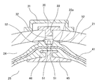
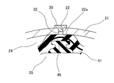
- the accumulator 11 is provided with a communication passage 51 for communicating the space 32 by the gas sealing port 22 with the gas sealing chamber 24 in a state where the diaphragm 41 is in contact with the opening peripheral portion 22a of the gas sealing port 22.
- the communication passage 51 is formed by an uneven shape provided on the diaphragm 41, more specifically, by the projection 52.
- the diaphragm 41 integrally forms a plurality of (four equal in FIG. 2) radial projections 52 having a rib shape on the plane of the poppet attachment portion 46.
- the spaces between the protrusions 52 adjacent to each other constitute a communication passage 51 for communicating the space 32 by the gas filling port 22 with the gas filling chamber 24.
- the communication passage 51 brings the space 32 by the gas filling port 22 into communication with the gas filling chamber 24. Therefore, even if the diaphragm 41 contacts the opening peripheral portion 22 a of the gas injection port 22, the space 32 and the gas injection chamber 24 by the gas injection port 22 remain in communication with each other. As a result, it is possible to suppress the generation of a differential pressure between the space 32 and the gas sealing chamber 24 by the gas inlet 22 and to prevent the diaphragm 41 from being damaged by the generation of the differential pressure.
- the accumulator 11 which exhibits such an effect can also correspond to the housing flattening structure in recent years.
- the projections 52 provided as the concavo-convex shape may be provided on the opening peripheral portion 22 a of the gas inlet 22 or may be provided on both the diaphragm 41 and the opening peripheral portion 22 a of the gas inlet 22. good.
- the uneven shape may be a groove (not shown) instead of the protrusion 52.
Landscapes
- Engineering & Computer Science (AREA)
- Physics & Mathematics (AREA)
- Fluid Mechanics (AREA)
- Mechanical Engineering (AREA)
- General Engineering & Computer Science (AREA)
- Supply Devices, Intensifiers, Converters, And Telemotors (AREA)
Abstract
アキュムレータハウジングの内部に設けられた可撓性を有するダイアフラムがガス封入口の開口周縁部に接触したときに、ガス封入口内の空間部とガス封入室との間の差圧の発生によりダイアフラムが破損するのを防止するために、ダイアフラムがガス封入口の開口周縁部に接触した状態で、ガス封入口内の空間部とガス封入室とを連通させる連通路を、例えばダイアフラムとガス封入口の開口周縁部とのいずれか一方又は両方に設けた凹凸形状によって形成する。
Description
本発明は、アキュムレータに係り、詳しくは、アキュムレータハウジングの内部に可撓性を備えるダイアフラムを設けたダイアフラム型アキュムレータに関する。本発明のアキュムレータは例えば、自動車用車載アキュムレータとして用いられる。
ダイアフラム型アキュムレータは、例えば図4に示すように、アキュムレータハウジング21の内部に、可撓性を備えるダイアフラム41を設けている。ダイアフラム型アキュムレータ11のアキュムレータハウジング21は、ガス封入口22およびオイルポート23を設けている。ダイアフラム41は、アキュムレータハウジング21の内部空間をガス封入口22に通じるガス封入室24と、オイルポート23に通じるフルード室25とに仕切っている。
ダイアフラム41は一般的に、樹脂またはゴムの積層構造を有しており、外周取付部42と、可撓部43と、ポペット取付部46とを一体に有している。外周取付部42は、アキュムレータハウジング21の側部内面に設けたダイアフラム保持部29に保持される。可撓部43は、アキュムレータハウジング21の内部の圧力変動に応じて変形する。ポペット取付部46は、可撓部43の平面中央に設けられている。
図4に示すアキュムレータ11には、以下の点で改良の余地がある。
ダイアフラム41は、アキュムレータハウジング21の内部に圧力変動が生じると、圧力均衡点を求めて変形する。フルード室25側の圧力(液圧)が極端に大きくなると、図5に示すように、ダイアフラム41は、ガス封入口22の開口周縁部22aに接触する。ガス封入口22は、ガス封入後に密栓30で閉塞され、閉塞後も、密栓30の内側に空間部32を残す。
ダイアフラム41は、ガス封入口22の開口周縁部22aに接触するとシール作用を発揮し、ガス封入口22に設けられた空間部32とガス封入室24との連通を遮断する。その結果、連通を遮断された空間部32とガス封入室24との間に差圧が発生し、大きな差圧が発生するとダイアフラム41が破損することがある。
近年、アキュムレータ11は、高圧縮対応のために、球体ではなく、扁平化構造のアキュムレータハウジング21を用いることが多い。扁平化構造のアキュムレータハウジング21では特に、ダイアフラム41がガス封入口22の開口周縁部22aに密着しやすい。このためこの種のアキュムレータハウジング21では、差圧の発生によるダイアフラム41の破損を防止することが強く望まれる。
本発明の課題は、ダイアフラムがガス封入口の開口周縁部に接触したときに、ダイアフラムが破損するのを防止することができるアキュムレータを提供することである。
本発明のアキュムレータは、ガス封入口を設けたアキュムレータハウジングと、圧力変動に伴う変形時に前記ガス封入口の開口周縁部に接触するように、アキュムレータハウジングの内部に設けられた可撓性を有するダイアフラムと、前記ダイアフラムが前記ガス封入口の開口周縁部に接触した状態で、前記ガス封入口内の空間部と前記ガス封入室とを連通させる連通路と、を備える。
本発明によれば、ダイアフラムがガス封入口の開口周縁部に接触してもガス封入口内の空間部とガス封入室とは連通した状態に維持され、ガス封入口内の空間部とガス封入室との間に差圧が発生せず、差圧の発生によりダイアフラムが破損するのを防止することができる。
図1は、実施の一形態のアキュムレータ11の全体断面図を示している。アキュムレータ11は、アキュムレータハウジング21の内部に可撓性を備えるダイアフラム41を設けたダイアフラム型アキュムレータである。
アキュムレータ11は、ガス封入口22およびオイルポート23を中心軸線上に設けたアキュムレータハウジング21を有している。アキュムレータハウジング21の内部には、ダイアフラム41が設けられている。ダイアフラム41は、アキュムレータハウジング21の内部空間を、ガス封入口22に通じるガス封入室(ガス室)24とオイルポート23に通じるフルード室(液室)25とに仕切る。
アキュムレータハウジング21の内面は、金属部品の絞り加工によってシェル26を形成することから、断面円弧形の曲面27,28の組み合わせ形状を有している。アキュムレータハウジング21の最大内径部には、ダイアフラム41を保持するための断面L字のフック状を呈する環状のダイアフラム保持部(ホルダ)29が設けられている。ハウジング21内面に形成される曲面は、ガス封入口側の曲面27とオイルポート側の曲面28との組み合わせ形状を有している。曲面27は、ガス封入口22側からオイルポート23側へかけて内径寸法が徐々に拡大する向きに生成されている。曲面28は反対に、オイルポート23側からガス封入口22側へかけて内径寸法が徐々に拡大する向きに生成されている。オイルポート側の曲面28は、円筒面からの絞り加工によって形成されている。
ガス封入口22はガス封入後、密栓30で閉塞され、外側にカバー31が被せられている。密栓30による閉塞後も、密栓30の内側には、空間部32が設けられている。
ダイアフラム41は、樹脂またはゴムの積層構造を有している。ダイアフラム41は、環状の外周取付部42と、可撓部43と、断面略U字形を呈する環状の反転部44とを一体に有している。外周取付部42は、ダイアフラム保持部29に保持される。可撓部43は、アキュムレータハウジング21内部の圧力変動に応じて変形する。反転部44は、外周取付部42と可撓部43との間に設けられ、可撓部43と共に変形する。可撓部43は、その平面中央に、ダイアフラム41がオイルポート23の透孔にはみ出すのを抑制するポペット45を取り付けたポペット取付部46を設けている。ダイアフラム41は、ブラダとも称される。
ポペット取付部46のガス封入室24側の面(図における上面)は、平面状に形成されるのが一般である。この面が平面状に形成された場合には上記したように、アキュムレータ11の作動時、フルード室25側の圧力(液圧)が極端に大きくなったときに、ポペット取付部46がガス封入口22の開口周縁部22aに接触してシール作用をなす。この場合、ガス封入口22による空間部32とガス封入室24との連通が遮断され、差圧を発生させることがある。
本実施の形態のアキュムレータ11は、ダイアフラム41がガス封入口22の開口周縁部22aに接触した状態で、ガス封入口22による空間部32とガス封入室24とを連通させる連通路51を設けている。この連通路51は、ダイアフラム41に設けた凹凸形状、より詳細には突起52によって生成されている。
図2(A)(B)に示すように、ダイアフラム41は、ポペット取付部46の平面上にリブ状を呈する突起52を複数(図では4等配)放射状に一体に形成している。互いに隣り合う突起52間の空間は、ガス封入口22による空間部32とガス封入室24とを連通させる連通路51を構成する。
作用として、図3に示すように、ダイアフラム41がガス封入口22の開口周縁部22aに接触したとき、連通路51は、ガス封入口22による空間部32とガス封入室24とを連通させる。このためガス封入口22による空間部32とガス封入室24とは、ダイアフラム41がガス封入口22の開口周縁部22aに接触しても、連通したままの状態を維持する。その結果ガス封入口22による空間部32とガス封入室24との間に差圧が発生するのを抑制することでき、差圧の発生によりダイアフラム41が破損するのを防止することができる。このような作用を奏するアキュムレータ11は、近年におけるハウジング扁平化構造にも対応することができる。
別の実施の形態として、凹凸形状として設けられた突起52は、ガス封入口22の開口周縁部22aに設けても良く、ダイアフラム41およびガス封入口22の開口周縁部22aの双方に設けても良い。
さらに別の実施の形態として、凹凸形状は、突起52の代わりに、溝(図示せず)であっても良い。
11 アキュムレータ
21 アキュムレータハウジング
22 ガス封入口
22a 開口周縁部
23 オイルポート
24 ガス封入室
25 フルード室
26 シェル
27,28 曲面
29 ダイアフラム保持部
30 密栓
31 カバー
32 空間部
41 ダイアフラム
42 外周取付部
43 可撓部
44 反転部
45 ポペット
46 ポペット取付部
51 連通路
52 突起
21 アキュムレータハウジング
22 ガス封入口
22a 開口周縁部
23 オイルポート
24 ガス封入室
25 フルード室
26 シェル
27,28 曲面
29 ダイアフラム保持部
30 密栓
31 カバー
32 空間部
41 ダイアフラム
42 外周取付部
43 可撓部
44 反転部
45 ポペット
46 ポペット取付部
51 連通路
52 突起
Claims (7)
- ガス封入口を設けたアキュムレータハウジングと、
圧力変動に伴う変形時に前記ガス封入口の開口周縁部に接触するように、アキュムレータハウジングの内部に設けられた可撓性を有するダイアフラムと、
前記ダイアフラムが前記ガス封入口の開口周縁部に接触した状態で、前記ガス封入口内の空間部と前記ガス封入室とを連通させる連通路と、
を備えることを特徴とするアキュムレータ。 - 前記連絡路は、前記ダイアフラムに設けられた凹凸形状によって生成されている、
ことを特徴とする請求項1に記載のアキュムレータ。 - 前記連絡路は、前記ガス封入口の開口周縁部に設けられた凹凸形状によって生成されている、
ことを特徴とする請求項1に記載のアキュムレータ。 - 前記連絡路は、前記ダイアフラムと前記ガス封入口の開口周縁部との双方に設けられた凹凸形状によって生成されている、
ことを特徴とする請求項1に記載のアキュムレータ。 - 前記凹凸形状は、複数個が放射状に設けられている、
ことを特徴とする請求項2ないし4のいずれか一に記載のアキュムレータ。 - 前記凹凸形状は、突起の形状を有している、
ことを特徴とする請求項2ないし4のいずれか一に記載のアキュムレータ。 - 前記凹凸形状は、溝の形状を有している、
ことを特徴とする請求項2ないし4のいずれか一に記載のアキュムレータ。
Priority Applications (4)
| Application Number | Priority Date | Filing Date | Title |
|---|---|---|---|
| EP18838605.6A EP3660329A4 (en) | 2017-07-25 | 2018-07-24 | ACCUMULATOR |
| JP2019532640A JP6979071B2 (ja) | 2017-07-25 | 2018-07-24 | アキュムレータ |
| CN201880040517.XA CN110770453B (zh) | 2017-07-25 | 2018-07-24 | 蓄能器 |
| US16/624,721 US20210156402A1 (en) | 2017-07-25 | 2018-07-24 | Accumulator |
Applications Claiming Priority (2)
| Application Number | Priority Date | Filing Date | Title |
|---|---|---|---|
| JP2017143584 | 2017-07-25 | ||
| JP2017-143584 | 2017-07-25 |
Publications (1)
| Publication Number | Publication Date |
|---|---|
| WO2019022080A1 true WO2019022080A1 (ja) | 2019-01-31 |
Family
ID=65039686
Family Applications (1)
| Application Number | Title | Priority Date | Filing Date |
|---|---|---|---|
| PCT/JP2018/027726 Ceased WO2019022080A1 (ja) | 2017-07-25 | 2018-07-24 | アキュムレータ |
Country Status (5)
| Country | Link |
|---|---|
| US (1) | US20210156402A1 (ja) |
| EP (1) | EP3660329A4 (ja) |
| JP (1) | JP6979071B2 (ja) |
| CN (1) | CN110770453B (ja) |
| WO (1) | WO2019022080A1 (ja) |
Families Citing this family (2)
| Publication number | Priority date | Publication date | Assignee | Title |
|---|---|---|---|---|
| CN112483483B (zh) * | 2020-11-26 | 2023-03-31 | 河南工业职业技术学院 | 一种智能的隔膜蓄能器 |
| CN118430494B (zh) * | 2024-07-04 | 2024-11-15 | 苏州好博医疗器械股份有限公司 | 一种具有分离功能的气路消音装置 |
Citations (2)
| Publication number | Priority date | Publication date | Assignee | Title |
|---|---|---|---|---|
| JPS58149601U (ja) * | 1982-03-31 | 1983-10-07 | 三菱電線工業株式会社 | 補強布入りブラダ |
| JP2007270872A (ja) | 2006-03-30 | 2007-10-18 | Tokai Rubber Ind Ltd | アキュムレータおよびアキュムレータ用ダイヤフラム |
Family Cites Families (7)
| Publication number | Priority date | Publication date | Assignee | Title |
|---|---|---|---|---|
| GB802702A (en) * | 1956-04-06 | 1958-10-08 | Dewandre Co Ltd C | Improvements in or relating to hydraulic accumulators |
| FR1546366A (fr) * | 1967-12-05 | 1968-11-15 | Bosch Gmbh Robert | Récipient à fluide sous pression |
| FR2662638B1 (fr) * | 1990-05-31 | 1997-09-05 | Nok Corp | Feuille laminee resistante au froid et formant barriere aux gaz, vessie pour accumulateur et accumulateur la comprenant. |
| FR2793852B1 (fr) * | 1999-05-19 | 2002-05-10 | Peugeot Citroen Automobiles Sa | Sphere ou accumulateur a membrane comportant un element dont les caracteristiques mecaniques chutent a partir d'une temperature determinee |
| JP5474333B2 (ja) * | 2008-11-05 | 2014-04-16 | イーグル工業株式会社 | アキュムレータ |
| CN202883510U (zh) * | 2012-11-07 | 2013-04-17 | 王凯 | 一种球形隔膜式蓄能器 |
| CN104564856A (zh) * | 2014-11-20 | 2015-04-29 | 常州市安家热工仪表有限公司 | 隔膜蓄能器 |
-
2018
- 2018-07-24 WO PCT/JP2018/027726 patent/WO2019022080A1/ja not_active Ceased
- 2018-07-24 EP EP18838605.6A patent/EP3660329A4/en not_active Withdrawn
- 2018-07-24 US US16/624,721 patent/US20210156402A1/en not_active Abandoned
- 2018-07-24 CN CN201880040517.XA patent/CN110770453B/zh active Active
- 2018-07-24 JP JP2019532640A patent/JP6979071B2/ja active Active
Patent Citations (2)
| Publication number | Priority date | Publication date | Assignee | Title |
|---|---|---|---|---|
| JPS58149601U (ja) * | 1982-03-31 | 1983-10-07 | 三菱電線工業株式会社 | 補強布入りブラダ |
| JP2007270872A (ja) | 2006-03-30 | 2007-10-18 | Tokai Rubber Ind Ltd | アキュムレータおよびアキュムレータ用ダイヤフラム |
Non-Patent Citations (1)
| Title |
|---|
| See also references of EP3660329A4 * |
Also Published As
| Publication number | Publication date |
|---|---|
| JPWO2019022080A1 (ja) | 2020-05-28 |
| EP3660329A1 (en) | 2020-06-03 |
| JP6979071B2 (ja) | 2021-12-08 |
| EP3660329A4 (en) | 2021-03-31 |
| CN110770453A (zh) | 2020-02-07 |
| US20210156402A1 (en) | 2021-05-27 |
| CN110770453B (zh) | 2021-09-07 |
Similar Documents
| Publication | Publication Date | Title |
|---|---|---|
| CN104583606B (zh) | 蓄能器 | |
| JP6147946B1 (ja) | 密封装置 | |
| TWI526642B (zh) | 流體壓力裝置 | |
| US10900568B2 (en) | Sealing structure | |
| CN111133236B (zh) | 密封装置及其组装方法 | |
| CN102822573A (zh) | 隔膜 | |
| TW201833442A (zh) | 具有定子連結密封件之泵總成 | |
| JP5790674B2 (ja) | リリーフ弁装置 | |
| JPWO2019022080A1 (ja) | アキュムレータ | |
| JP6957618B2 (ja) | アキュムレータ | |
| JP5177391B2 (ja) | ピストンシール構造 | |
| KR102751267B1 (ko) | 다방향 전환 밸브의 실링부재 및 그를 포함하는 다방향 전환 밸브 | |
| JP5982354B2 (ja) | 流体制御弁 | |
| US11073223B2 (en) | Fluid control valve | |
| JP2018151002A5 (ja) | ||
| US11313469B2 (en) | Sealing structure | |
| JP2015196510A (ja) | リザーバキャップ | |
| WO2016173543A1 (zh) | 弹性密封件和密封组件 | |
| WO2018230306A1 (ja) | 密封装置 | |
| JP2018197588A (ja) | ガスケット及び密封構造 | |
| JP2015140861A (ja) | 密封装置 | |
| JP7423434B2 (ja) | セグメントシール | |
| JP2003336601A (ja) | アキュムレータ | |
| JP2013238254A (ja) | ダイヤフラム装置とそれを用いた調圧リザーバ | |
| JP4324782B2 (ja) | 密封装置 |
Legal Events
| Date | Code | Title | Description |
|---|---|---|---|
| 121 | Ep: the epo has been informed by wipo that ep was designated in this application |
Ref document number: 18838605 Country of ref document: EP Kind code of ref document: A1 |
|
| ENP | Entry into the national phase |
Ref document number: 2019532640 Country of ref document: JP Kind code of ref document: A |
|
| NENP | Non-entry into the national phase |
Ref country code: DE |
|
| ENP | Entry into the national phase |
Ref document number: 2018838605 Country of ref document: EP Effective date: 20200225 |