WO2019026146A1 - 燃料電池システムの制御方法、及び、燃料電池システム - Google Patents
燃料電池システムの制御方法、及び、燃料電池システム Download PDFInfo
- Publication number
- WO2019026146A1 WO2019026146A1 PCT/JP2017/027757 JP2017027757W WO2019026146A1 WO 2019026146 A1 WO2019026146 A1 WO 2019026146A1 JP 2017027757 W JP2017027757 W JP 2017027757W WO 2019026146 A1 WO2019026146 A1 WO 2019026146A1
- Authority
- WO
- WIPO (PCT)
- Prior art keywords
- fuel
- gas
- temperature
- cathode gas
- fuel cell
- Prior art date
- Legal status (The legal status is an assumption and is not a legal conclusion. Google has not performed a legal analysis and makes no representation as to the accuracy of the status listed.)
- Ceased
Links
Images






Classifications
-
- H—ELECTRICITY
- H01—ELECTRIC ELEMENTS
- H01M—PROCESSES OR MEANS, e.g. BATTERIES, FOR THE DIRECT CONVERSION OF CHEMICAL ENERGY INTO ELECTRICAL ENERGY
- H01M8/00—Fuel cells; Manufacture thereof
- H01M8/04—Auxiliary arrangements, e.g. for control of pressure or for circulation of fluids
- H01M8/04007—Auxiliary arrangements, e.g. for control of pressure or for circulation of fluids related to heat exchange
- H01M8/04014—Heat exchange using gaseous fluids; Heat exchange by combustion of reactants
- H01M8/04022—Heating by combustion
-
- H—ELECTRICITY
- H01—ELECTRIC ELEMENTS
- H01M—PROCESSES OR MEANS, e.g. BATTERIES, FOR THE DIRECT CONVERSION OF CHEMICAL ENERGY INTO ELECTRICAL ENERGY
- H01M8/00—Fuel cells; Manufacture thereof
- H01M8/04—Auxiliary arrangements, e.g. for control of pressure or for circulation of fluids
- H01M8/04082—Arrangements for control of reactant parameters, e.g. pressure or concentration
- H01M8/04201—Reactant storage and supply, e.g. means for feeding, pipes
-
- H—ELECTRICITY
- H01—ELECTRIC ELEMENTS
- H01M—PROCESSES OR MEANS, e.g. BATTERIES, FOR THE DIRECT CONVERSION OF CHEMICAL ENERGY INTO ELECTRICAL ENERGY
- H01M8/00—Fuel cells; Manufacture thereof
- H01M8/04—Auxiliary arrangements, e.g. for control of pressure or for circulation of fluids
- H01M8/04223—Auxiliary arrangements, e.g. for control of pressure or for circulation of fluids during start-up or shut-down; Depolarisation or activation, e.g. purging; Means for short-circuiting defective fuel cells
- H01M8/04225—Auxiliary arrangements, e.g. for control of pressure or for circulation of fluids during start-up or shut-down; Depolarisation or activation, e.g. purging; Means for short-circuiting defective fuel cells during start-up
-
- H—ELECTRICITY
- H01—ELECTRIC ELEMENTS
- H01M—PROCESSES OR MEANS, e.g. BATTERIES, FOR THE DIRECT CONVERSION OF CHEMICAL ENERGY INTO ELECTRICAL ENERGY
- H01M8/00—Fuel cells; Manufacture thereof
- H01M8/04—Auxiliary arrangements, e.g. for control of pressure or for circulation of fluids
- H01M8/04298—Processes for controlling fuel cells or fuel cell systems
- H01M8/043—Processes for controlling fuel cells or fuel cell systems applied during specific periods
- H01M8/04302—Processes for controlling fuel cells or fuel cell systems applied during specific periods applied during start-up
-
- H—ELECTRICITY
- H01—ELECTRIC ELEMENTS
- H01M—PROCESSES OR MEANS, e.g. BATTERIES, FOR THE DIRECT CONVERSION OF CHEMICAL ENERGY INTO ELECTRICAL ENERGY
- H01M8/00—Fuel cells; Manufacture thereof
- H01M8/04—Auxiliary arrangements, e.g. for control of pressure or for circulation of fluids
- H01M8/04298—Processes for controlling fuel cells or fuel cell systems
- H01M8/04313—Processes for controlling fuel cells or fuel cell systems characterised by the detection or assessment of variables; characterised by the detection or assessment of failure or abnormal function
- H01M8/0432—Temperature; Ambient temperature
- H01M8/04328—Temperature; Ambient temperature of anode reactants at the inlet or inside the fuel cell
-
- H—ELECTRICITY
- H01—ELECTRIC ELEMENTS
- H01M—PROCESSES OR MEANS, e.g. BATTERIES, FOR THE DIRECT CONVERSION OF CHEMICAL ENERGY INTO ELECTRICAL ENERGY
- H01M8/00—Fuel cells; Manufacture thereof
- H01M8/04—Auxiliary arrangements, e.g. for control of pressure or for circulation of fluids
- H01M8/04298—Processes for controlling fuel cells or fuel cell systems
- H01M8/04313—Processes for controlling fuel cells or fuel cell systems characterised by the detection or assessment of variables; characterised by the detection or assessment of failure or abnormal function
- H01M8/0432—Temperature; Ambient temperature
- H01M8/04373—Temperature; Ambient temperature of auxiliary devices, e.g. reformers, compressors, burners
-
- H—ELECTRICITY
- H01—ELECTRIC ELEMENTS
- H01M—PROCESSES OR MEANS, e.g. BATTERIES, FOR THE DIRECT CONVERSION OF CHEMICAL ENERGY INTO ELECTRICAL ENERGY
- H01M8/00—Fuel cells; Manufacture thereof
- H01M8/04—Auxiliary arrangements, e.g. for control of pressure or for circulation of fluids
- H01M8/04298—Processes for controlling fuel cells or fuel cell systems
- H01M8/04694—Processes for controlling fuel cells or fuel cell systems characterised by variables to be controlled
- H01M8/04701—Temperature
- H01M8/04738—Temperature of auxiliary devices, e.g. reformer, compressor, burner
-
- H—ELECTRICITY
- H01—ELECTRIC ELEMENTS
- H01M—PROCESSES OR MEANS, e.g. BATTERIES, FOR THE DIRECT CONVERSION OF CHEMICAL ENERGY INTO ELECTRICAL ENERGY
- H01M8/00—Fuel cells; Manufacture thereof
- H01M8/04—Auxiliary arrangements, e.g. for control of pressure or for circulation of fluids
- H01M8/04298—Processes for controlling fuel cells or fuel cell systems
- H01M8/04694—Processes for controlling fuel cells or fuel cell systems characterised by variables to be controlled
- H01M8/04746—Pressure; Flow
- H01M8/04753—Pressure; Flow of fuel cell reactants
-
- H—ELECTRICITY
- H01—ELECTRIC ELEMENTS
- H01M—PROCESSES OR MEANS, e.g. BATTERIES, FOR THE DIRECT CONVERSION OF CHEMICAL ENERGY INTO ELECTRICAL ENERGY
- H01M8/00—Fuel cells; Manufacture thereof
- H01M8/04—Auxiliary arrangements, e.g. for control of pressure or for circulation of fluids
- H01M8/04298—Processes for controlling fuel cells or fuel cell systems
- H01M8/04694—Processes for controlling fuel cells or fuel cell systems characterised by variables to be controlled
- H01M8/04746—Pressure; Flow
- H01M8/04776—Pressure; Flow at auxiliary devices, e.g. reformer, compressor, burner
-
- H—ELECTRICITY
- H01—ELECTRIC ELEMENTS
- H01M—PROCESSES OR MEANS, e.g. BATTERIES, FOR THE DIRECT CONVERSION OF CHEMICAL ENERGY INTO ELECTRICAL ENERGY
- H01M8/00—Fuel cells; Manufacture thereof
- H01M8/06—Combination of fuel cells with means for production of reactants or for treatment of residues
- H01M8/0606—Combination of fuel cells with means for production of reactants or for treatment of residues with means for production of gaseous reactants
-
- H—ELECTRICITY
- H01—ELECTRIC ELEMENTS
- H01M—PROCESSES OR MEANS, e.g. BATTERIES, FOR THE DIRECT CONVERSION OF CHEMICAL ENERGY INTO ELECTRICAL ENERGY
- H01M8/00—Fuel cells; Manufacture thereof
- H01M8/06—Combination of fuel cells with means for production of reactants or for treatment of residues
- H01M8/0606—Combination of fuel cells with means for production of reactants or for treatment of residues with means for production of gaseous reactants
- H01M8/0612—Combination of fuel cells with means for production of reactants or for treatment of residues with means for production of gaseous reactants from carbon-containing material
- H01M8/0618—Reforming processes, e.g. autothermal, partial oxidation or steam reforming
-
- H—ELECTRICITY
- H01—ELECTRIC ELEMENTS
- H01M—PROCESSES OR MEANS, e.g. BATTERIES, FOR THE DIRECT CONVERSION OF CHEMICAL ENERGY INTO ELECTRICAL ENERGY
- H01M8/00—Fuel cells; Manufacture thereof
- H01M8/10—Fuel cells with solid electrolytes
- H01M8/12—Fuel cells with solid electrolytes operating at high temperature, e.g. with stabilised ZrO2 electrolyte
- H01M2008/1293—Fuel cells with solid oxide electrolytes
-
- Y—GENERAL TAGGING OF NEW TECHNOLOGICAL DEVELOPMENTS; GENERAL TAGGING OF CROSS-SECTIONAL TECHNOLOGIES SPANNING OVER SEVERAL SECTIONS OF THE IPC; TECHNICAL SUBJECTS COVERED BY FORMER USPC CROSS-REFERENCE ART COLLECTIONS [XRACs] AND DIGESTS
- Y02—TECHNOLOGIES OR APPLICATIONS FOR MITIGATION OR ADAPTATION AGAINST CLIMATE CHANGE
- Y02E—REDUCTION OF GREENHOUSE GAS [GHG] EMISSIONS, RELATED TO ENERGY GENERATION, TRANSMISSION OR DISTRIBUTION
- Y02E60/00—Enabling technologies; Technologies with a potential or indirect contribution to GHG emissions mitigation
- Y02E60/30—Hydrogen technology
- Y02E60/50—Fuel cells
Definitions
- the present invention relates to a fuel cell system control method and a fuel cell system.
- SOFC solid oxide fuel cell
- the supply of fuel gas It is necessary to supply the cathode gas from the front.
- POX partial oxidation
- Some fuel cell systems use the property that POX reforming is an exothermic reaction to warm up a fuel processor at system startup (WO2013 / 035771A1).
- An object of the present invention is to provide a control method of a fuel cell system which suppresses an excessive temperature rise at the time of start-up, and a fuel cell system.
- the fuel cell system is configured to at least reform the fuel by using the solid oxide fuel cell that generates electric power by receiving the supply of the anode gas and the cathode gas.
- a fuel processor that generates anode gas and supplies the generated anode gas to a fuel cell, and a combustor that burns the supplied fuel to warm up the fuel processor, and the fuel cell system includes at least a system Control is performed while the warm-up is performed at the time of start-up.
- a control method of a fuel cell system includes a cathode gas supply step of supplying a cathode gas to a fuel processor, a determination step of determining whether a temperature of a gas passing through the fuel processor exceeds a reformable temperature, and a gas A cathode gas reducing step of reducing the amount of cathode gas supplied to the fuel processor when it is determined that the temperature of the fuel gas exceeds the reformable temperature, and a fuel supply step of supplying fuel to the fuel processor .
- FIG. 1 is a block diagram of a fuel cell system according to a first embodiment.
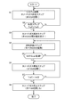
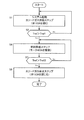
- FIG. 2 is a flowchart of warm-up control.
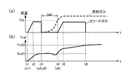
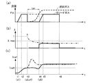
- FIG. 3 is a diagram showing changes in the flow rates of the fuel gas and the cathode gas and the outlet temperature.
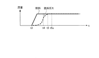
- FIG. 4 is a diagram showing changes in fuel and fuel gas flow rates.
- FIG. 5A is a configuration diagram of the evaporator at time t3 in FIG.
- FIG. 5B is a block diagram of the evaporator at time t4 in FIG.
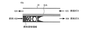
- FIG. 5C is a block diagram of the evaporator at time t5a in FIG.
- FIG. 6 is a flowchart of warm-up control in the prior art.
- FIG. 5A is a configuration diagram of the evaporator at time t3 in FIG.
- FIG. 5B is a block diagram of the evaporator at time t4 in FIG.
- FIG. 5C is a block diagram of the evaporator at time
- FIG. 7 is a view showing changes in flow rates of cathode gas and fuel gas, excess air ratio, and outlet temperature.
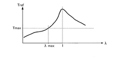
- FIG. 8 is a diagram showing the relationship between the excess air ratio and the outlet temperature.
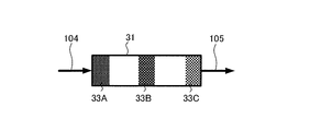
- FIG. 9 is a schematic block diagram of a reformer.
- FIG. 10 is a diagram showing changes in temperature of each part of the reformer.
- FIG. 11 is a graph showing the relationship between the waiting time and the liquid fuel temperature in the second embodiment.
- FIG. 12 is a flowchart of warm-up control.
- FIG. 13 is a flowchart of warm-up control in the third embodiment.
- FIG. 14 is a block diagram of a fuel cell system according to a fourth embodiment.
- FIG. 15 is a diagram showing changes in the flow rates of the fuel gas and the cathode gas and the outlet temperature.
- FIG. 16 is a diagram showing changes in the flow rates of the fuel gas and the cathode gas and the outlet temperature.
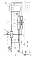
- FIG. 1 is a block diagram showing a main configuration of a solid oxide fuel cell (SOFC) system according to a first embodiment.
- SOFC solid oxide fuel cell
- the fuel cell stack 1 which is an SOFC, includes an electrolyte layer formed of solid oxide such as ceramic, an anode electrode (fuel electrode) to which an anode gas (fuel gas) as fuel is supplied, and an air containing oxygen as a cathode. It is a stack of cells configured to be sandwiched by a cathode electrode (air electrode) supplied as a gas (oxidizing gas).
- a fuel such as hydrogen contained in the anode gas is reacted with oxygen in the cathode gas to generate power, and a cathode gas after the reaction (anode off gas) and a cathode gas (cathode off gas) after the reaction. Drain.
- a fuel cell system 100 including the fuel cell stack 1 a fuel supply system for supplying an anode gas to the fuel cell stack 1 and a cathode gas for the fuel cell stack 1 are provided. And an exhaust system for exhausting the anode off gas and the cathode off gas outside the fuel cell system 100.
- the fuel cell system 100 is an example of a power generation device provided with a fuel cell.
- the fuel supply system includes a fuel tank 2, a fuel processor 3, and the like.
- the fuel processor 3 includes an evaporator 31, a heater 32, and a reformer 33.
- the air supply system includes a cathode compressor 4 and an air heat exchanger 5.
- the exhaust system includes an exhaust combustor 6.
- the fuel cell system 100 also includes a controller 7 that controls the operation of the entire system. The controller 7 controls the fuel cell system 100 by controlling each component of the fuel cell system 100, a motor, a valve, and the like.
- fuel such as water-containing ethanol stored in the fuel tank 2 is sent out to the path 101 by using the pump 2A juxtaposed to the fuel tank 2.
- the path 101 is branched into two paths 102 and 103.
- the path 102 is provided with a pump 102A
- the path 103 is provided with a pump 103A.
- a fuel thermometer 101T for measuring the temperature of the fuel is provided.
- the pumps 2A, 102A, and 103A are examples of a fuel supply unit.
- the fuel delivered from the fuel tank 2 via the path 102 is supplied to the evaporator 31.
- the evaporator 31 utilizes the heat of the exhaust gas from the exhaust combustor 6 to vaporize the liquid fuel to generate a fuel gas.
- the fuel gas produced in the evaporator 31 reaches the heater 32 via the path 104.
- the heater 32 is provided adjacent to the exhaust combustor 6 and is further heated to a temperature at which the fuel gas can be reformed by the reformer 33 using the combustion heat of the exhaust combustor 6 Can do the machine.
- the reformer 33 When the fuel gas heated by the heater 32 reaches the reformer 33, it is reformed into an anode gas by a catalytic reaction. Then, the anode gas is supplied from the reformer 33 to the anode electrode of the fuel cell stack 1 via the passage 105.
- the cathode gas is supplied to the heater 32 from the air supply system, and the cathode gas supplied to the heater 32 reaches the reformer 33.
- the fuel gas and the cathode gas react with each other, and an exothermic reaction proceeds. Since the amount of heat generation in the exhaust combustor 6 is small immediately after startup, the reformer 33 is also warmed up by the exothermic reaction in the reformer 33.
- thermometer 105 T is provided in the path 105, and the gas temperature of the anode gas and the cathode gas passing through the reformer 33 can be measured. Since the temperature at the outlet of the reformer 33 is measured by the thermometer 105T, hereinafter, the temperature measured by the thermometer 105T will be described as the outlet temperature Tref.
- the fuel delivered from the fuel tank 2 via the path 103 is supplied to the exhaust combustor 6. A detailed description of the exhaust combustor 6 will be given later in the description of the exhaust system. Note that, for example, when the fuel is hydrous ethanol, the anode gas contains methane, hydrogen, carbon monoxide, and the like.
- air which is cathode gas taken in from the outside
- the path 111 is branched into two paths 112 and 113.
- the path 112 is provided with a valve 112A and the path 113 is provided with a valve 113A.
- the cathode compressor 4 is an example of a cathode gas supply unit.
- the cathode gas delivered from the cathode compressor 4 via the paths 111 and 112 reaches the air heat exchanger 5.
- the air heat exchanger 5 uses the heat of the exhaust gas from the exhaust combustor 6 to heat the cathode gas.
- the heated cathode gas is supplied to the fuel cell stack 1 via the passage 113.
- the fuel cell stack 1 is supplied with the anode gas from the fuel supply system and the cathode gas from the air supply system.
- the cathode gas delivered from the cathode compressor 4 through the paths 111 and 113 is supplied to the heater 32.
- the anode off gas is discharged from the fuel cell stack 1 via a path 121 and the cathode off gas is discharged via a path 122.
- the anode off gas and the cathode off gas are combusted by the oxidation catalytic reaction in the exhaust combustor 6 and discharged as exhaust gas.
- the heat generated with the combustion is transferred to the heater 32 and the reformer 33 adjacent to the exhaust combustor 6.
- the exhaust gas reaches the evaporator 31 via the path 123 and then reaches the air heat exchanger 5 via the path 124. Then, the exhaust gas is discharged from the air heat exchanger 5 to the outside of the fuel cell system 100 via the passage 125.
- the exhaust combustor 6 is made of a ceramic material such as alumina, mixes an anode off gas and a cathode off gas, burns the mixed gas by an oxidation catalyst, and generates an exhaust gas mainly composed of carbon dioxide and water. .
- the exhaust combustor 6 burns the unburned gas contained in the exhaust from the fuel cell stack 1.
- the exhaust gas contains almost no unburned gas, and sufficient combustion can not be performed. Therefore, by supplying fuel to the exhaust combustor 6 via the path 103, it is possible to warm up by burning the exhaust combustor 6.
- the exhaust gas from the exhaust combustor 6 is discharged to the outside of the fuel cell system 100 through the evaporator 31 and the air heat exchanger 5 in this order, but the invention is not limited thereto.
- the fuel processor 3 when the evaporator 31 and the heater 32 are provided to be separated, the exhaust gas from the exhaust combustor 6 passes through the air heat exchanger 5 and the evaporator 31 in order of fuel It may be configured to be discharged out of the battery system 100.
- the controller 7 controls the entire fuel cell system 100 by controlling the components of the fuel cell system 100 and the valves in each system.
- the controller 7 is constituted by a microcomputer provided with a central processing unit (CPU), a read only memory (ROM), a random access memory (RAM) and an input / output interface (I / O interface).
- the controller 7 stores a program, and executes the stored program to execute warm-up control, normal power generation control, and the like described later.
- warm-up control of the fuel cell system 100 will be described using the flowchart of FIG.
- the warm-up control is performed when the fuel cell system 100 is started.
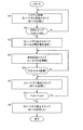
- FIG. 2 is a flowchart of warm-up control of the fuel cell system 100.
- step S1 system start-up and a cathode gas supply step are performed.
- the controller 7 starts the cathode compressor 4 and opens the valve 112A. In this way, the supply of the cathode gas to the fuel cell stack 1 is started. At the same time, the controller 7 drives the pump 2A and the pump 103A to start the supply of fuel to the exhaust combustor 6. When the exhaust combustor 6 burns the supplied fuel, heating of the heater 32 and the reformer 33 is started.
- a cathode gas supply step is performed.
- the controller 7 opens the valve 113A to start the supply of the cathode gas to the heater 32.
- step S2 a determination step is performed.
- the controller 7 determines whether the outlet temperature Tref of the fuel processor 3 measured by the thermometer 105T exceeds the reformable temperature Tref1.
- the reformable temperature Tref1 is a lower limit temperature at which the reformer 33 can perform reforming, and the reformer 33 can start reforming at a temperature higher than the reformable temperature Tref1.
- step S3 When the outlet temperature Tref exceeds the reformable temperature Tref1 (S2: Yes), the controller 7 next performs the process of step S3 to start the reforming.
- the controller 7 returns to step S1 and performs the process.
- step S3 a cathode gas reducing step is performed.
- the controller 7 reduces the valve opening amount of the valve 113A to reduce the supply amount of the cathode gas to the heater 32 and the reformer 33.
- the controller 7 may stop the supply of the cathode gas by closing the valve 113A. Then, the controller 7 next performs the process of step S4.
- step S4 a fuel supply step is performed.
- the controller 7 drives the pump 102A to start the supply of fuel from the fuel tank 2 to the evaporator 31.
- the fuel flows into the evaporator 31, the fuel is vaporized in the evaporator 31 to generate a fuel gas.
- the generated fuel gas flows into the heater 32 and is heated, and then reformed into the anode gas in the reformer 33. Then, the anode gas is supplied to the fuel cell stack 1 through the path 105.
- step S5 the controller 7 determines whether or not a waiting time tair has elapsed after execution of step S4.
- the generation amount of the fuel gas in the evaporator 31 rises slowly after the execution of step S4 and gradually increases. Therefore, it is necessary to obtain in advance a time from the start of fuel supply to the evaporator 31 until the flow rate of the fuel gas generated by the evaporator 31 exceeds a threshold which is a sufficient amount, and the time is the standby time tair Used as
- step S6 If the waiting time tair has elapsed (S5: Yes), the controller 7 next executes step S6. If the standby time tair has not elapsed (S5: No), the controller 7 returns to step S4 and continues the process.
- step S6 a cathode gas increase step is performed.
- the controller 7 increases the opening amount of the valve 113A, and increases the supply amount of the cathode gas to the heater 32 and the reformer 33.
- the controller 7 opens the valve 113A. In this state, since the fuel gas and the cathode gas are supplied to the reformer 33, the fuel gas and the anode gas react with each other, and the outlet temperature Tref further rises.
- step S7 the controller 7 determines whether the outlet temperature Tref has exceeded the warm-up completion temperature Tref2.
- the warm-up completion temperature Tref2 is a temperature at which the reformer 33 can appropriately perform reforming, and the controller 7 ends the warm-up control when the reformer 33 reaches the warm-up completion temperature Tref2.
- the warm-up completion temperature Tref2 is higher than the reformable temperature Tref1.
- step S8 the controller 7 next performs the process of step S8 to end the warming-up operation.
- the controller 7 returns to step S6 and performs the process.
- step S8 a cathode gas stop step is performed.
- the controller 7 stops the supply of the cathode gas to the heater 32 and the reformer 33 to end the warm-up control. Further, the controller 7 may stop the motor 103A to stop the supply of fuel to the exhaust combustor 6. The controller 7 performs the usual power generation control of the fuel cell stack 1 thereafter.
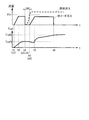
- FIG. 3 is a diagram showing temporal changes in the flow rates of the fuel gas and the cathode gas supplied to the reformer 33 and the outlet temperature Tref when the warm-up control of FIG. 2 is performed.
- time is shown on the x-axis, and the flow rates of fuel gas and cathode gas are shown on the y-axis.
- FIG. 3 (b) the time is shown on the x-axis and the outlet temperature Tref is shown on the y-axis.
- the valve 113A is closed and the flow rate of the cathode gas becomes zero.
- a system start is performed and a cathode gas supply step (S1) is performed.
- a cathode gas supply step is performed, and when the valve 113A is opened, supply of the cathode gas is started.
- the flow rate of the cathode gas gradually increases after time t1, and reaches the supply target value at time t2, and becomes constant at the supply target value after time t2.
- the outlet temperature Tref starts rising after time t1. This is because, in the reformer 33, the reaction between the fuel gas and the cathode gas proceeds to cause an exothermic reaction.
- the controller 7 executes the cathode gas reduction step (S3) and the fuel supply step (S4) after the determination of "Yes" in the determination step (S2).
- the valve 113A is closed to stop the supply of the cathode gas to the reformer 33.
- the pump 102A is driven to start the supply of fuel to the evaporator 31.
- the flow rate of the fuel gas exceeds the threshold Fth.
- the threshold Fth the time from the start of supply of fuel to the evaporator 31 to the time the flow rate of the fuel gas becomes the threshold Fth is set as the standby time tair.
- the waiting time tair is determined based on the vaporization characteristic in which the liquid fuel is vaporized in the evaporator 31.
- the controller 7 performs the cathode gas increase step (S6) after the determination of "Yes" in step S5.
- the valve 113A is opened, and the supply of the cathode gas to the reformer 33 is resumed.
- the ratio of the cathode gas to the fuel gas is suppressed, so that excessive heating in the reformer 33 is less likely to occur.
- the flow rate of the cathode gas gradually increases after time t4, similarly to the time from t1 to t3, and becomes constant when reaching the supply target value at time t5. Due to the exothermic reaction in the reformer 33 in addition to the combustion of the exhaust combustor 6, the outlet temperature Tref continues to rise.
- the controller 7 executes the cathode gas stop step (S8) after the determination of "Yes" in step S7.
- the cathode gas stop step (S8) when the valve 113A is closed, the supply of the cathode gas to the reformer 33 is stopped. Thus, the warm-up control is completed.
- FIG. 4 the flow rate of the fuel gas supplied to the reformer 33 shown in FIG. 3A is shown by a dotted line, and the flow rate of the fuel supplied to the evaporator 31 is shown by a solid line. Further, in addition to the times t3, t4 and t5, the time 5a at which the flow rates of the fuel and the fuel gas become constant is shown in FIG.
- FIGS. 5A to 5C The detailed configuration of the evaporator 31 at various times is shown in FIGS. 5A to 5C.
- 5A shows the evaporator 31 at time t3
- FIG. 5B shows the evaporator 31 at time t4
- FIG. 5C shows the evaporator 31 at time t5a.
- the evaporator 31 is provided between the fuel system path 102 and the fuel path 104 and between the exhaust system path 123 and the fuel path 124. There is.
- the fuel system and the exhaust system are adjacent via the adjacent surface 31A. Further, a region where fuel is present in the fuel system is referred to as a fuel liquid phase region.
- the heat of the exhaust gas in the exhaust system is transmitted to the adjacent surface 31A provided between the fuel system and the exhaust system.
- the adjacent surface 31A When the adjacent surface 31A is heated, the fuel present on the adjacent surface 31A is vaporized to generate a fuel gas.
- the fuel liquid phase region In order to vaporize all of the supplied fuel, the fuel liquid phase region must be present at a predetermined ratio or more of the adjacent surfaces 31A.
- the supply of fuel to evaporator 31 is started at time t3, and the supply of fuel gas to reformer 33 is also started.
- the fuel liquid phase region does not exist in all of the adjacent surfaces 31A, and the ratio of the fuel liquid phase region to the adjacent surface 31A is relatively small. Therefore, the flow rate of the fuel gas generated by vaporization at the adjacent surface 31A is smaller than the flow rate of the supplied fuel.
- the evaporator 31 is supplied with more fuel, and the proportion of the fuel liquid phase region is increased. Therefore, since the ratio of the fuel liquid phase region in the adjacent surface 31A increases, the flow rate of the fuel gas gradually increases.
- the fuel liquid phase region comes to exist at a certain ratio or more of the adjacent surfaces 31A, and all the supplied fuel is stabilized. It takes time to vaporize. Therefore, in the case where the fuel is liquid, the delay in rising of the flow rate of the fuel gas from the start of supply of the liquid fuel becomes remarkable.
- FIG. 6 is a flowchart showing warm-up control according to the prior art. According to this figure, in comparison with the warm-up control of this embodiment of FIG. 2, the processes of steps S3, S5, and S6 are deleted, and steps S1, S2, S4, S7, and S8 are executed. Be done.
- FIG. 7 shows changes over time in the flow rates of the cathode gas and the fuel gas, the excess air ratio ⁇ , and the outlet temperature Tref.
- the flow rate of the cathode gas is indicated by a solid line, and the flow rate of the fuel gas is indicated by a dotted line. Furthermore, the flow rate of the cathode gas when the warm-up control of FIG. 6 is performed is indicated by an alternate long and short dash line.
- FIG. 7 (b) shows the change of the excess air ratio ⁇ .
- the excess air ratio ⁇ is a ratio of the flow rate of the cathode gas to the flow rate of the fuel gas.
- the excess air ratio ⁇ is equal to 1, all of the cathode gas reacts with the fuel gas.
- the excess air ratio ⁇ is larger than 1, the amount of heat generated by the reformer 33 is large because the amount of the cathode gas is larger than that of the fuel gas.
- FIG. 7 (c) shows the change of the outlet temperature Tref similarly to FIG. 3 (b). Furthermore, in this figure, the outlet temperature Tref in the case where the warm-up control of FIG. 6 is performed is indicated by an alternate long and short dash line.
- the case where the prior art warm-up control is performed is indicated by an alternate long and short dash line.
- the processes of steps S3 and S6 are omitted. Therefore, between time t3 and t4, the supply of the cathode gas is not interrupted and does not change with the target value for supply.
- the rise of the flow rate of the fuel gas after the start of supply of the fuel is late after the time t3, the flow rate of the fuel gas is extremely small.
- the flow rate of the cathode gas is the supply target value, and the flow rate of the fuel gas is extremely small. ⁇ greatly exceeds 1. Then, as the flow rate of the fuel gas increases with the passage of time, the excess air ratio ⁇ gradually decreases.
- the supply of the cathode gas is interrupted between times t3 and t4, so the excess air ratio ⁇ is zero. Then, at time t4, the supply of the cathode gas is resumed with the flow rate of the fuel gas exceeding the threshold Fth. Therefore, the excess air ratio ⁇ becomes relatively small, and after the time t4, the excess air ratio ⁇ gradually increases without rapidly increasing.
- the excess air ratio ⁇ becomes significantly larger than 1 after time t3. Therefore, in the reformer 33, the fuel gas and the cathode gas The reaction proceeds and the outlet temperature Tref rapidly rises.
- the increase of the excess air ratio ⁇ is suppressed. Therefore, the outlet temperature Tref does not change between time t3 and t4, and gradually increases after time t4.
- the upper limit temperature Tmax for avoiding the deterioration of the reformer 33 is shown, and when the outlet temperature Tref exceeds the upper limit temperature Tmax, the reformer 33 may be damaged. However, before the excess air ratio ⁇ rises to 1, the outlet temperature Tref exceeds the upper limit temperature Tmax. Therefore, the excess air ratio ⁇ when the outlet temperature Tref becomes the upper limit temperature Tmax is determined as the upper limit excess air ratio ⁇ max. Then, by controlling the excess air ratio ⁇ so as to be lower than the upper excess air ratio ⁇ max, the outlet temperature Tref can be prevented from becoming the upper limit temperature Tmax, and the reformer 33 can be protected.
- the excess air ratio ⁇ is controlled to be lower than the upper excess air ratio ⁇ max, so the outlet temperature Tref does not exceed the upper limit temperature Tmax. , The reformer 33 can be protected.
- the detailed configuration of the reformer 33 is shown in FIG.
- the upstream side to which the fuel gas is supplied through the passage 104 is referred to as an upstream portion 33A
- the downstream side discharging the cathode gas through the passage 105 is referred to as a downstream portion 33C
- the upstream portion 33A A portion between the downstream portion 33C and the downstream portion 33C is referred to as a midstream portion 33B.
- FIG. 10 shows the temperature of each point in the reformer 33 when the warm-up control of FIG. 6 is performed.
- the temperature of the upstream portion 33A is indicated by a solid line
- the temperature of the middle stream portion 33B is indicated by an alternate long and short dash line
- the temperature of the downstream portion 33C is indicated by an alternate long and two short dashes line.
- the upper limit temperature Tmax is shown in this figure.
- the fuel gas is supplied in the order of the upstream portion 33A, the midstream portion 33B, and the downstream portion 33C. Therefore, in the upstream portion 33A, the excess air ratio ⁇ becomes relatively large, so it is easy to generate heat. On the other hand, in the downstream portion 33C, since the flow rate of the fuel gas to be reached is relatively small, the excess air ratio ⁇ is relatively small and it is difficult to generate heat. As described above, since the temperature tends to increase in the order of the upstream portion 33A, the midstream portion 33B, and the downstream portion 33C, the upper limit temperature Tmax may be exceeded in the upstream portion 33A.
- a graph using the temperature T of the upstream portion 33A instead of the outlet temperature Tref in the y-axis in FIG. 8 is prepared, and the excess air ratio ⁇ when the temperature T of the upstream portion 33A becomes the upper limit temperature Tmax is the upper limit air It is preferable to set the excess rate ⁇ max. By doing this, the upstream portion 33A can surely fall below the upper limit temperature Tmax, so that the reformer 33 can be protected.
- the upper limit temperature Tmax may be set with a margin or may be set to a limit value as a temperature at which the reforming catalyst starts to deteriorate.
- the reduction amount of the cathode gas in the case of reducing the valve opening amount of the valve 113A will be considered.
- the calorific value when all the cathode gas is completely oxidized with the fuel gas can be expressed as Q (fa) as a function of the flow rate fa of the cathode gas.
- the heat capacity of the catalyst of the reformer 33 is C
- the relationship between the heat capacity C, the calorific value Q (fa), the reformable temperature Tref1, the upper limit temperature Tmax, and the waiting time tair is expressed by the following equation. Can be shown.
- the reformable temperature Tref1 is the outlet temperature Tref when the cathode gas reducing step (S3) is performed.
- the controller 7 executes the cathode gas supply step (S1) at the time of system startup to start supply of the cathode gas to the reformer 33.
- the cathode gas reduction step (S3) is executed to set the cathode gas to the reformer 33 The supply amount is reduced, and the fuel supply step (S4) is performed to start the supply of the fuel gas to the reformer 33.
- the cathode gas is supplied from the cathode gas supply step (S1) and has a sufficient flow rate. Therefore, by performing the cathode gas reducing step (S3) to reduce the flow rate of the cathode gas, the ratio of the cathode gas to the fuel gas can be reduced, and the excess air ratio ⁇ can be controlled to be low. By doing so, excessive heat generation can be suppressed, so that the reformer 33 can be protected.
- the flow rate of the cathode gas to the reformer 33 may be reduced.
- the excess air ratio ⁇ can be lowered and an excessive rise in the temperature of the reformer 33 can be suppressed.
- the outlet temperature Tref rises. Since the time until the outlet temperature Tref reaches the warm-up completion temperature Tref2 can be shortened, the time until the warm-up completion can be shortened.
- the supply of the cathode gas to the reformer 33 may be stopped in the cathode gas reducing step (S3).
- the excess air ratio ⁇ is further lowered, so that the excessive rise in temperature of the reformer 33 is further suppressed, and the reformer 33 can be protected more reliably.
- the controller 7 increases the cathode gas increase step (S4). Execute S6). Immediately after the start of the fuel supply, the rise of the supply amount of fuel gas is slow, but the flow rate of the fuel gas exceeds the threshold Fth after the waiting time tair. Therefore, even if the cathode gas increasing step (S6) is performed to increase the flow rate of the cathode gas, the flow rate of the fuel gas exceeds the threshold Fth, so that the increase of the excess air ratio ⁇ is suppressed. Therefore, excessive heating of the reformer 33 is further suppressed, and the reformer 33 can be protected.
- the fuel is liquid
- the fuel processor 3 vaporizes the fuel in the evaporator 31 to generate a fuel gas
- the reformer 33 produces the fuel gas. It reforms and produces anode gas.
- the controller 7 increases the cathode gas increase step (S6). To do).
- the standby time tair is set in consideration of the vaporization characteristic of the liquid fuel. Then, after the flow rate of the fuel gas supplied to the reformer 33 exceeds the threshold Fth after the standby time tair has elapsed, the cathode gas increase step (S6) is performed to suppress the increase in the excess air ratio ⁇ . While the fuel gas and the cathode gas are reacted, the reformer 33 can be warmed up.
- the cathode gas stop step (S8) is performed.
- the warm-up completion temperature Tref2 it is not necessary to further perform warm-up control, so the supply of the cathode gas to the reformer 33 is stopped, and the progress of the reaction between the fuel gas and the cathode gas is stopped. Complete machine control. By doing this, after that, the warm-up of the reformer 33 is completed, and power generation control of the fuel cell stack 1 is performed using the anode gas generated by reforming the fuel gas in the reformer 33. You can
- the controller 7 may change the standby time tair according to the temperature of the liquid fuel.
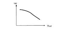
- FIG. 11 is a graph showing the relationship between the waiting time tair and the liquid fuel temperature Tfuel.
- the liquid fuel temperature Tfuel is shown on the x-axis, and the waiting time tair is shown on the y-axis.
- the liquid fuel temperature Tfuel is measured by the fuel thermometer 101T.
- the standby time tair is set to be shorter as the liquid fuel temperature Tfuel is higher.
- FIG. 12 is a flowchart of activation control according to the present embodiment. As compared with the flowchart of the activation control of the first embodiment shown in FIG. 2, the flowchart of this flowchart is added with the processing of step S11 between the processing of step S4 and the processing of step S5.
- step S11 a waiting time setting step is performed.
- the controller 7 refers to the graph shown in FIG. 11 and determines the waiting time tair based on the liquid fuel temperature Tfuel measured by the fuel thermometer 101T. Specifically, as shown in FIG. 11, as the liquid fuel temperature Tfuel is higher, the waiting time tair is set smaller. By doing this, it is possible to set an appropriate waiting time tair according to the temperature of the fuel.
- the standby time setting step (S11) is performed.
- the controller 7 sets the standby time tair to be smaller as the liquid fuel temperature Tfuel measured by the fuel thermometer 101T is higher.
- step S2 when the outlet temperature Tref exceeds the reformable temperature Tref1 in the determination step (S2), the process proceeds to step S3, but the invention is not limited thereto.
- the temperature of the evaporator 31 may be further taken into consideration.
- FIG. 13 is a flowchart of the warm-up control of the present embodiment. As compared with the flowchart of the warm-up control of the first embodiment shown in FIG. 2, the process of step S2 is changed to the process of step S22 in this flowchart.
- step S22 a determination step is performed.
- the controller 7 determines whether the outlet temperature Tref exceeds the reformable temperature Tref1 and the evaporator temperature Tvap is higher than the vaporizable temperature Tvap1.
- the evaporator temperature Tvap is measured by an evaporator thermometer 125T provided in a path 125 connected to the evaporator 31.
- the evaporator 31 when the evaporator temperature Tvap exceeds the gasifiable temperature Tvap1, the vaporization of the fuel proceeds. Conversely, when the evaporator temperature Tvap is lower than the vaporizable temperature Tvap1, the fuel is less likely to be vaporized.
- the evaporator temperature Tvap exceeds the vaporizable temperature Tvap1 by performing the determination process of step S22 and the evaporator 31 is sufficiently heated to vaporize the fuel (step S22: Yes), the fuel supply step (S4)
- the supply of fuel to the evaporator 31 is started, so that the vaporization of the fuel proceeds appropriately.
- the fuel supply step (S4) is performed.
- the fuel supply step (S4) is performed only when the evaporator temperature Tvap exceeds the vaporizable temperature Tvap1 and the evaporator 31 is sufficiently heated to vaporize the fuel (step S22: Yes). Fuel can be properly vaporized. Therefore, since the fuel gas is appropriately generated, the flow rate of the fuel gas exceeds the threshold Fth after the waiting time tair has elapsed (S5: Yes).
- the reformer 33 can be warmed up by reacting the fuel gas with the cathode gas while suppressing the increase in the excess air ratio ⁇ .
- FIG. 14 is a block diagram of a fuel cell system 100 of the present embodiment.
- fuel gas is stored in the fuel tank 2, and a fuel blower 2B is provided instead of the pump 2A.
- valves 102B and 103B are provided instead of the pumps 102A and 103A.
- the fuel blower 2B and the valves 102B and 103B are an example of the fuel supply unit.
- FIG. 15 shows a flowchart of the warm-up control.
- step S31 is performed instead of step S5.
- the controller 7 determines whether or not the standby time tair2 has elapsed after step S4. In this way, when the waiting time tair2 has elapsed (S31: Yes), the flow rate of the fuel gas to the reformer 33 exceeds Fth, so the fuel excess rate ⁇ is suppressed while increasing the fuel
- the reformer 33 can be warmed up by reacting the gas with the cathode gas.
- the controller 7 executes the cathode gas supply step (S1) at the time of system startup to start supply of the cathode gas to the reformer 33.
- the cathode gas reduction step (S3) is executed to reduce the amount of cathode gas supplied to the reformer 33.
- the fuel supply step (S4) is performed to start the supply of fuel gas to the reformer 33.
- the rise of the supply amount of fuel gas to the reformer 33 is slow.
- the supply of the cathode gas is started from the cathode gas supply step (S1), and reaches the supply target value. Therefore, by performing the cathode gas reduction step (S3) to reduce the flow rate of the cathode gas, the ratio of the flow rate of the cathode gas to the flow rate of the fuel gas, that is, the excess air ratio ⁇ can be lowered. 33 can be protected.
Landscapes
- Engineering & Computer Science (AREA)
- Chemical & Material Sciences (AREA)
- Life Sciences & Earth Sciences (AREA)
- Manufacturing & Machinery (AREA)
- Sustainable Development (AREA)
- Sustainable Energy (AREA)
- Chemical Kinetics & Catalysis (AREA)
- Electrochemistry (AREA)
- General Chemical & Material Sciences (AREA)
- Combustion & Propulsion (AREA)
- Fuel Cell (AREA)
Abstract
燃料電池システムの制御方法によれば、燃料電池システムは、アノードガス及びカソードガスの供給を受けて発電する固体酸化物型の燃料電池と、燃料を少なくとも改質することでアノードガスを生成し、生成したアノードガスを燃料電池に供給する燃料処理器と、供給される燃料を燃焼させて燃料処理器の暖機を行う燃焼器と、を備え、燃料電池システムは少なくともシステム起動時における前記暖機が行われる間において制御される。燃料電池システムの制御方法は、カソードガスを燃料処理器に供給するカソードガス供給ステップと、燃料処理器を通過するガスの温度が改質可能温度を上回るか否かを判定する判定ステップと、ガスの温度が改質可能温度を上回ると判定される場合に、燃料処理器へのカソードガスの供給量を減少させるカソードガス減少ステップと、燃料を燃料処理器に供給する燃料供給ステップと、を有する。
Description
本発明は、燃料電池システムの制御方法、及び、燃料電池システムに関する。
固体酸化物型燃料電池(SOFC:Solid Oxide Fuel Cell)は、アノードガスとカソードガス(空気)との供給を受け、比較的高温で動作することが知られている。このような燃料電池を備える燃料電池システムにおいては、少なくとも燃料を改質する燃料処理器が設けられており、燃料処理器は、改質可能な温度にまで暖機された後に、燃料ガスを改質してアノードガスを生成する。
燃料処理器が改質可能温度に到達したか否かを判定するために、燃料処理器の出口近傍に温度センサが設けることにより、燃料処理器の温度を取得する場合には、燃料ガスの供給前からカソードガスを供給する必要がある。燃料ガスの供給前からカソードガスが供給されると、POX(Partial Oxidation:部分酸化)改質が行われることが知られている。燃料電池システムの中には、POX改質が発熱反応である性質を利用して、システム起動時の燃料処理器の暖機を行うものもある(WO2013/035771A1)。
燃料ガスの供給前からカソードガスを供給する場合には、燃料ガスが供給されるタイミングでは燃料ガスに比べて酸素が過剰な状態になる。そのため、燃料ガスと酸素との反応が進行しやすくなり、燃料処理器において局所的に温度が過剰に上昇してしまい、燃料処理器の改質性能が劣化するおそれがある。そこで、システム起動時の暖機処理中における過剰な温度上昇を抑制する燃料電池システムの検討が必要であった。
本発明の目的は、起動時における過剰な温度上昇を抑制する燃料電池システムの制御方法、及び、燃料電池システムを提供することである。
本発明の一態様の燃料電池システムの制御方法によれば、燃料電池システムは、アノードガス及びカソードガスの供給を受けて発電する固体酸化物型の燃料電池と、燃料を少なくとも改質することでアノードガスを生成し、生成したアノードガスを燃料電池に供給する燃料処理器と、供給される燃料を燃焼させて燃料処理器の暖機を行う燃焼器と、を備え、燃料電池システムは少なくともシステム起動時における前記暖機が行われる間において制御される。燃料電池システムの制御方法は、カソードガスを燃料処理器に供給するカソードガス供給ステップと、燃料処理器を通過するガスの温度が改質可能温度を上回るか否かを判定する判定ステップと、ガスの温度が改質可能温度を上回ると判定される場合に、燃料処理器へのカソードガスの供給量を減少させるカソードガス減少ステップと、燃料を燃料処理器に供給する燃料供給ステップと、を有する。
以下、添付図面を参照しながら本発明の実施形態について説明する。
(第1実施形態)
図1は、第1実施形態における固体酸化物型燃料電池(SOFC:Solid Oxide Fuel Cell)システムの主要構成を示すブロック図である。
図1は、第1実施形態における固体酸化物型燃料電池(SOFC:Solid Oxide Fuel Cell)システムの主要構成を示すブロック図である。
SOFCである燃料電池スタック1は、セラミック等の固体酸化物で形成された電解質層を、燃料であるアノードガス(燃料ガス)が供給されるアノード電極(燃料極)と、酸素を含む空気がカソードガス(酸化ガス)として供給されるカソード極(空気極)により挟み込んで構成されたセルを積層したものである。燃料電池スタック1では、アノードガス中に含まれる水素などの燃料とカソードガス中の酸素とを反応させて発電を行い、反応後のアノードガス(アノードオフガス)と反応後のカソードガス(カソードオフガス)を排出する。
燃料電池スタック1を備える固体酸化物型燃料電池システム(以後、燃料電池システムと称す)100には、燃料電池スタック1にアノードガスを供給する燃料供給系統と、燃料電池スタック1にカソードガスを供給する空気供給系統と、燃料電池システム100外にアノードオフガス及びカソードオフガスを排気する排気系統とが設けられている。なお、燃料電池システム100は、燃料電池を備える発電装置の一例である。
燃料供給系統は、燃料タンク2や、燃料処理器3などを含む。なお、燃料処理器3は、蒸発器31、加熱器32、及び、改質器33により構成されている。空気供給系統は、カソードコンプレッサー4、空気熱交換器5を含む。排気系統は、排気燃焼器6を含む。また、燃料電池システム100は、システム全体の動作を制御するコントローラ7を備えている。コントローラ7は、燃料電池システム100の各構成、モータ、及び、弁などを制御することで、燃料電池システム100を制御する。
以下では、それぞれの系統について詳細に説明する。まず、燃料供給系統の詳細について説明する。
燃料供給系統においては、燃料タンク2に蓄えられている含水エタノールなどの燃料が、燃料タンク2に併設されたポンプ2Aを用いて、経路101に送り出される。経路101は2つの経路102、103に分岐し、経路102にはポンプ102Aが、経路103にはポンプ103Aが設けられている。なお、経路101には、燃料の温度を測定する燃料温度計101Tが設けられている。なお、ポンプ2A、102A、103Aは、燃料供給部の一例である。
経路102を介して燃料タンク2から送り出された燃料は、蒸発器31に供給される。蒸発器31は、排気燃焼器6からの排気ガスの熱を利用して、液体の燃料を気化させて燃料ガスを生成する。
蒸発器31において生成される燃料ガスは、経路104を介して加熱器32に到達する。加熱器32は、排気燃焼器6と隣接して設けられており、排気燃焼器6の燃焼熱を利用して、燃料ガスを改質器33にて改質できる温度までさらに加熱することで暖機を行うことができる。
加熱器32にて加熱された燃料ガスは、改質器33に到達すると、触媒反応によってアノードガスに改質される。そして、アノードガスは、改質器33から経路105を介して燃料電池スタック1のアノード電極に供給される。
なお、加熱器32には、空気供給系統からカソードガスが供給されており、加熱器32に供給されるカソードガスは改質器33へと到達する。燃料電池システム100の起動直後においては、改質器33においては燃料ガスとカソードガスとが反応し発熱反応が進行する。なお、起動直後においては、排気燃焼器6における発熱量が少ないため、改質器33における発熱反応によっても、改質器33の暖機が行われる。
また、経路105には温度計105Tが設けられており、改質器33を通過するアノードガスやカソードガスのガス温度を測定することができる。なお、温度計105Tによっては改質器33の出口の温度が測定されることになるので、以下において、温度計105Tにより測定される温度を出口温度Trefと称して説明する。一方、経路103を介して燃料タンク2から送り出される燃料は、排気燃焼器6に供給される。排気燃焼器6の詳細な説明は、後の排気系統の説明において行う。なお、例えば、燃料が含水エタノールである場合には、アノードガスは、メタン、水素、一酸化炭素などを含んでいる。
次に、空気供給系統の詳細について説明する。
空気供給系統においては、外部から取り込まれたカソードガスである空気は、カソードコンプレッサー4によって経路111から燃料電池システム100に供給される。経路111は、2つの経路112、113に分岐しており、経路112には弁112Aが、経路113には弁113Aが設けられている。カソードコンプレッサー4は、カソードガス供給部の一例である。
カソードコンプレッサー4から、経路111、112を介して送り出されたカソードガスは、空気熱交換器5に到達する。
空気熱交換器5は、排気燃焼器6からの排気ガスの熱を利用して、カソードガスを加熱する。加熱されたカソードガスは、経路113を介して燃料電池スタック1に供給される。このようにして、燃料電池スタック1には、燃料供給系統からアノードガスが供給されるとともに、空気供給系統からカソードガスが供給される。
一方、カソードコンプレッサー4から、経路111、113を介して送り出されたカソードガスは、加熱器32に供給される。
次に、排気系統の詳細について説明する。
燃料電池スタック1からは、経路121を介してアノードオフガスが排出され、経路122を介してカソードオフガスが排出される。アノードオフガス及びカソードオフガスは、排気燃焼器6において酸化触媒反応によって燃焼されて、排気ガスとして排出される。燃焼に伴って発生する熱は、排気燃焼器6に隣接する加熱器32や改質器33に伝達される。排気ガスは、経路123を介して蒸発器31に到達した後に、経路124を介して空気熱交換器5に到達する。そして、排気ガスは、空気熱交換器5から経路125を介して燃料電池システム100の外部に排出される。
排気燃焼器6は、アルミナなどのセラミック材料により構成されており、アノードオフガスとカソードオフガスを混合し、その混合ガスを酸化触媒によって燃焼させ、二酸化炭素や水を主成分とする排気ガスを生成する。このようにして、排気燃焼器6は、燃料電池スタック1からの排気に含まれる未燃ガスを燃焼させる。
しかしながら、燃料電池システム100の起動直後などにおいては、排気にほとんど未燃ガスが含まれておらず、十分な燃焼を行うことができない。そこで、排気燃焼器6に経路103を介して燃料を供給することにより、排気燃焼器6を燃焼させることで暖機を行うことができる。
なお、排気系統については、排気燃焼器6からの排気が、蒸発器31、空気熱交換器5の順に通り、燃料電池システム100外へと排出される例について説明したが、これに限らない。たとえば、燃料処理器3において、蒸発器31と加熱器32とが離間するように設けられている場合には、排気燃焼器6からの排気が空気熱交換器5、蒸発器31の順に通り燃料電池システム100外へと排出されるように構成されてもよい。
コントローラ7は、燃料電池システム100の各構成や各系統における弁などを制御することで、燃料電池システム100全体を制御する。なお、コントローラ7は、中央演算装置(CPU)、読み出し専用メモリ(ROM)、ランダムアクセスメモリ(RAM)及び入出力インタフェース(I/Oインタフェース)を備えたマイクロコンピュータで構成される。コントローラ7は、プログラムを記憶しており、記憶しているプログラムを実行することで、後述する暖機制御や通常の発電制御などを実行する。
ここで、燃料電池システム100の暖機制御ついて、図2のフローチャートを用いて説明する。この暖機制御は、燃料電池システム100の起動時に行われる。
図2は、燃料電池システム100の暖機制御のフローチャートである。
ステップS1においては、システム起動と、カソードガス供給ステップとが行われる。
システム起動において、コントローラ7は、カソードコンプレッサー4を起動させるとともに、弁112Aを開く。このようにすると、燃料電池スタック1へのカソードガスの供給が開始される。同時に、コントローラ7は、ポンプ2A、及び、ポンプ103Aを駆動して、排気燃焼器6への燃料の供給を開始する。排気燃焼器6が供給された燃料を燃焼すると、加熱器32、及び、改質器33の加熱が開始される。
システム起動の後に、カソードガス供給ステップが行われる。コントローラ7は、弁113Aを開き、加熱器32へのカソードガスの供給を開始させる。
次に、ステップS2において、判定ステップが実行される。コントローラ7は、温度計105Tにより測定される燃料処理器3の出口温度Trefが改質可能温度Tref1を上回っているか否かを判定する。改質可能温度Tref1は改質器33において改質が可能な下限温度であり、改質器33は、改質可能温度Tref1よりも高い温度において改質を開始することができる。
出口温度Trefが改質可能温度Tref1を上回る場合には(S2:Yes)、コントローラ7は、改質を開始するために、次に、ステップS3の処理を行う。出口温度Trefが改質可能温度Tref1以下である場合には(S2:No)、コントローラ7は、ステップS1に戻って処理を行う。
次に、ステップS3においては、カソードガス減少ステップが行われる。コントローラ7は、弁113Aの開弁量を小さくして、加熱器32、及び、改質器33へのカソードガスの供給量を減少させる。なお、コントローラ7は、弁113Aを閉じて、カソードガスの供給を停止してもよい。そして、コントローラ7は、次に、ステップS4の処理を行う。
ステップS4においては、燃料供給ステップが行われる。コントローラ7は、ポンプ102Aを駆動させて、燃料タンク2から蒸発器31への燃料の供給を開始する。燃料が蒸発器31に流入すると、蒸発器31において燃料が気化して燃料ガスが生成される。生成された燃料ガスは、加熱器32へ流入して加熱された後に、改質器33にてアノードガスへと改質される。そして、アノードガスは、経路105を経て燃料電池スタック1に供給される。
次に、ステップS5においては、コントローラ7はステップS4の実行後に待機時間tairだけ経過したか否かを判定する。ここで、蒸発器31における燃料ガスの生成量は、ステップS4の実行直後では立ち上がりが遅く、徐々に大きくなる。そこで、予め、蒸発器31への燃料供給の開始から、蒸発器31にて生成される燃料ガスの流量が十分な量である閾値を上回るまでの時間を求めておき、その時間を待機時間tairとして用いる。
待機時間tair経過している場合には(S5:Yes)、コントローラ7は、次にステップS6を実行する。待機時間tair経過していない場合には(S5:No)、コントローラ7は、ステップS4に戻って処理を続ける。
ステップS6においては、カソードガス増加ステップが実行される。コントローラ7は、弁113Aの開弁量を大きくし、加熱器32、及び、改質器33へのカソードガスの供給量を増加させる。なお、ステップS3において弁113Aが閉じられる場合には、コントローラ7は、弁113Aを開く。この状態においては、改質器33に燃料ガスとカソードガスとが供給されるので、燃料ガスとアノードガスとが反応し、出口温度Trefはさらに上昇する。
次に、ステップS7においては、コントローラ7は、出口温度Trefが暖機完了温度Tref2を上回ったか否かを判定する。暖機完了温度Tref2は改質器33が改質を適切に行うことができる温度であり、コントローラ7は、改質器33が暖機完了温度Tref2に到達すると暖機制御を終了する。なお、暖機完了温度Tref2は、改質可能温度Tref1よりも高いものとする。
出口温度Trefが暖機完了温度Tref2を上回る場合には(S7:Yes)、コントローラ7は、暖機運転を終了させるために、次に、ステップS8の処理を行う。一方、出口温度Trefが暖機完了温度Tref2以下である場合には(S7:No)、コントローラ7は、ステップS6に戻って処理を行う。
ステップS8においては、カソードガス停止ステップが行われる。コントローラ7は、弁113Aを閉じると、加熱器32、及び、改質器33へのカソードガスの供給を停止して、暖気制御を終了させる。また、コントローラ7は、モータ103Aを停止して排気燃焼器6への燃料の供給を停止させてもよい。コントローラ7は、以降においては通常の燃料電池スタック1の発電制御を行う。
次に、図2の暖機制御が行われる場合の、改質器33へと供給される燃料ガスの流量、及び、カソードガスの流量について、図3を用いて説明する。
図3は、図2の暖機制御が行われる場合に、改質器33へ供給される燃料ガス、及び、カソードガスの流量と、出口温度Trefとの経時的な変化を示す図である。図3(a)には、x軸に時間が示され、y軸に燃料ガス及びカソードガスの流量が示されている。図3(b)には、x軸に時間が示され、y軸に出口温度Trefが示されている。なお、図3においては、ステップS3のカソードガス減少ステップにおいて、弁113Aが閉じられてカソードガスの流量はゼロになるものとする。
まず、時刻t1において、システム起動が行われるとともに、カソードガス供給ステップ(S1)が実行される。
図3(a)に示されるように、カソードガス供給ステップが実行され、弁113Aが開かれると、カソードガスの供給が開始される。カソードガスの流量は、時刻t1の後に徐々に大きくなり、時刻t2において供給目標値に達すると、時刻t2以降において供給目標値で一定となる。
図3(b)に示されるように、時刻t1の後において出口温度Trefが上昇を開始する。これは、改質器33において、燃料ガスとカソードガスとの反応が進行し、発熱反応がおこるからである。
時刻t3において、図3(b)に示されるように出口温度Trefが改質可能温度Tref1に到達する。この状態では、コントローラ7は、判定ステップ(S2)における「Yes」の判定を経て、カソードガス減少ステップ(S3)及び燃料供給ステップ(S4)を実行する。
カソードガス減少ステップ(S3)においては、弁113Aが閉じられて、改質器33へのカソードガスの供給が停止される。燃料供給ステップ(S4)においては、ポンプ102Aが駆動され、蒸発器31への燃料の供給が開始される。
図3(a)に示されるように、時刻t3の直後、すなわち、蒸発器31への燃料の供給の開始直後では、蒸発器31における燃料の気化速度が遅いので、燃料ガスの流量の立ち上がりが遅い。なお、燃料である液体を用いる場合の方が、気体である燃料ガスを用いる場合と比較すると、燃料ガスの流量の立ち上がりの遅さは顕著になる。なお、燃料が液体である場合の方が燃料ガスの流量の立ち上がりの遅さが顕著になる理由について、後に、図4から図5Cまでを用いて説明する。
時刻t4になり、すなわち、時刻t3から待機時間tairだけ経過すると、燃料ガスの流量は閾値Fthを上回る。ここで、カソードガスの流量が供給目標値であったとしても、燃料ガスが閾値Fthを上回っている場合には、燃料ガスに対するカソードガスの割合が大きくなりにくいので、改質器33にて過剰な加熱が抑制される。このような燃料ガスの流量が閾値Fthとして求められ、蒸発器31への燃料の供給開始から燃料ガスの流量が閾値Fthとなるまでの時間が待機時間tairとして設定される。このように、待機時間tairは、蒸発器31において液体の燃料が気化する気化特性に基づいて定められる。
時刻t4になると、コントローラ7は、ステップS5における「Yes」の判定を経て、カソードガス増加ステップ(S6)が実行される。カソードガス増加ステップにおいては、弁113Aが開かれ、改質器33へのカソードガスの供給が再開される。なお、燃料ガスの流量が閾値Fthを上回っているため、燃料ガスに対するカソードガスの割合が抑制されるので、改質器33において過剰な加熱は発生しにくい。
カソードガスの流量は、時刻t4以降においては、時刻t1からt3までと同様に、徐々に大きくなり時刻t5にて供給目標値に達すると一定となる。排気燃焼器6の燃焼に加えて、改質器33における発熱反応により、出口温度Trefは上昇を続ける。
時刻t6において、図3(b)に示すように出口温度Trefが暖機完了温度Tref2に到達する。この状態では、コントローラ7は、ステップS7における「Yes」の判定を経て、カソードガス停止ステップ(S8)が実行される。カソードガス停止ステップ(S8)においては、弁113Aが閉じられると、改質器33へのカソードガスの供給が停止される。このようにして暖気制御が完了される。
ここで、燃料が液体である場合の方が、燃料ガスの流量の立ち上がりの遅さは顕著になる理由について、図4から図5Cまでを用いて説明する。
図4には、図3(a)に示された改質器33に供給される燃料ガスの流量が点線で示され、蒸発器31へ供給される燃料の流量が実線で示されている。また、図4には、時刻t3、t4、及び、t5に加えて、燃料及び燃料ガスの流量が一定となる時刻5aが示されている。
図5Aから図5Cまでには、様々な時刻における蒸発器31の詳細な構成が示されている。図5Aは時刻t3における蒸発器31を示し、図5Bは時刻t4における蒸発器31を示し、図5Cは時刻t5aにおける蒸発器31を示している。
なお、図5Aから図5Cまでに示されるように、蒸発器31は、燃料系統の経路102と経路104との間に設けられるとともに、排気系統の経路123と経路124との間に設けられている。蒸発器31においては、燃料系統と排気系統とは隣接面31Aを介して隣接されている。また、燃料系統において燃料が存在する領域を、燃料液相領域と称するものとする。
排気系統における排気ガスの熱は、燃料系統と排気系統との間に設けられる隣接面31Aへと伝わる。隣接面31Aが加熱されると、隣接面31A上に存在する燃料は気化して燃料ガスが生成される。なお、供給される燃料の全てが気化するためには、隣接面31Aのうちの一定割合以上に燃料液相領域が存在しなければならない。
図4を参照すると、実線で示されるように、時刻t3において蒸発器31への燃料の供給が開始されるとともに、改質器33への燃料ガスの供給も開始される。
図5Aに示されるように、蒸発器31への燃料の供給が開始されても、隣接面31Aの全てにおいて燃料液相領域が存在せず、隣接面31Aに対する燃料液相領域の割合は比較的小さい。そのため、隣接面31Aにおいて気化により生成される燃料ガスの流量は、供給される燃料の流量に比べて小さい。
次に、再び図4を参照すると、時刻t4において、改質器33への燃料ガスの供給量が大きくなり始める。
図5Bに示されるように、蒸発器31にはより多くの燃料が供給され、燃料液相領域の割合が大きくなる。そのため、隣接面31Aにおける燃料液相領域の割合が増加するので、燃料ガスの流量は徐々に大きくなる。
次に、再び図4を参照すると、時刻t5aにおいて、供給される燃料の流量と燃料ガスの流量とは等しくなる。この状態では、燃料の供給量と、燃料から燃料ガスへの生成量とが等しくなる。
図5Cに示されるように、隣接面31Aのうちの一定割合以上に燃料液相領域が存在することになると、供給される燃料の全てが安定的に気化する。そのため、隣接面31Aの一部に燃料液相領域が存在する状態が定常的に続くことになる。
このように、蒸発器31に液体の燃料の供給を開始してから、隣接面31Aのうちの一定割合以上に燃料液相領域が存在するようになり、供給される燃料の全てが安定的に気化するようになるまでには時間を要する。したがって、燃料が液体である場合の方が、液体の燃料の供給開始からの燃料ガスの流量の立ち上がりの遅さは顕著になる。
ここで、図6から図8までを用いて、本実施形態による効果を説明する。
図6には、従来技術の暖機制御を示すフローチャートである。この図によれば、図2の本実施形態の暖機制御と比較すると、ステップS3、S5、及び、S6の処理が削除されており、ステップS1、S2、S4、S7、及び、S8が実行される。
図7には、カソードガス及び燃料ガスの流量、空気過剰率λ、及び、出口温度Trefの経時的な変化が示されている。
図7(a)においては、図3(a)と同様に、カソードガスの流量が実線で、燃料ガスの流量が点線で示されている。さらに、図6の暖機制御が行われる場合のカソードガスの流量が一点鎖線で示されている。
図7(b)には、空気過剰率λの変化が示されている。空気過剰率λは、燃料ガスの流量に対するカソードガスの流量の比率である。空気過剰率λが1と等しい場合には、カソードガスの全てが燃料ガスと反応する。空気過剰率λが1よりも大きい場合には、燃料ガスに比べてカソードガスが多いので、改質器33における発熱量が大きくなる。
なお、この図には、上限空気過剰率λmaxが示されている。空気過剰率λが上限空気過剰率λmaxを下回るように制御することで、改質器33における発熱反応を抑制することができる。上限空気過剰率λmaxについては、図8を用いて後に説明する。
図7(c)は、図3(b)と同様に、出口温度Trefの変化を示している。さらに、この図においては、図6の暖機制御が行われる場合の出口温度Trefが一点鎖線で示されている。
図7(a)を参照すると、従来技術の暖機制御が行われる場合が一点鎖線で示されている。従来技術においては、ステップS3、S6の処理が省略される。そのため、時刻t3からt4の間において、カソードガスの供給は中断されず供給目標値で変化しない。一方、時刻t3の後において、燃料の供給開始後の燃料ガスの流量の立ち上がりは遅いので、燃料ガスの流量は極めて少ない状態となる。
本実施形態の暖機制御が行われる場合が実線で示されている。従来技術によれば、ステップS3、S6の処理が行われるので、時刻t3からt4の間において、カソードガスの供給が中断されるのでカソードガスの流量は少ない。一方、時刻t4において、燃料ガスの流量は閾値Fthを上回る。
図7(b)を参照すると、一点鎖線で示される従来技術によれば、時刻t3においては、カソードガスの流量は供給目標値であり、かつ、燃料ガスの流量は極めて少ないので、空気過剰率λは1を大きく上回る。そして、時間の経過とともに燃料ガスの流量は大きくなると、空気過剰率λは徐々に低下する。
本実施形態によれば、実線で示されるように、時刻t3からt4までの間においては、カソードガスの供給が中断されるので、空気過剰率λはゼロである。そして、時刻t4においては、燃料ガスの流量が閾値Fthを上回った状態でカソードガスの供給が再開される。そのため、空気過剰率λは比較的小さくなり、時刻t4以降において空気過剰率λは急激に上昇せずに徐々に大きくなる。
図7(c)を参照すると、実線で示される従来技術によれば、時刻t3以降において、空気過剰率λが1よりも極めて大きくなるので、改質器33においては燃料ガスとカソードガスとの反応が進行し、出口温度Trefが急激に上昇してしまう。
本実施形態によれば、一点鎖線で示されるように、空気過剰率λの上昇が抑制されている。そのため、出口温度Trefは、時刻t3からt4までの間においては変化せず、時刻t4以降において徐々に上昇する。
このように、本実施形態によって、空気過剰率λの上昇が抑制されて、出口温度Trefが過剰に高くなることを防ぐことができる。
図8には、改質器33において、カソードガスの流量が供給目標値である時に、燃料ガスの流量を単調増加させる場合における、空気過剰率λと改質器33の出口温度Trefとの関係が示されている。
燃料ガスの流量を増加させると、空気過剰率λが増加し、燃料ガスとカソードガスとの反応が進行して、出口温度Trefは上昇する。空気過剰率λが1と等しくなると、燃料ガスの全てがカソードガスと反応するので、発熱量が大きくなり出口温度Trefは最大となる。空気過剰率λが1を超えると、燃料ガスの全てがカソードガスと反応するとともに、カソードガスの流量が多くなるので出口温度Trefは緩やかに下降する。
改質器33の劣化を回避するための上限温度Tmaxが示されており、出口温度Trefが上限温度Tmaxを上回る場合には改質器33が損傷するおそれがある。しかしながら、空気過剰率λが1まで上昇する前に、出口温度Trefは上限温度Tmaxを上回ってしまう。そこで、出口温度Trefが上限温度Tmaxとなる場合における空気過剰率λを、上限空気過剰率λmaxと定める。そして、上限空気過剰率λmaxを下回るように空気過剰率λを制御することで、出口温度Trefが上限温度Tmaxとなることが避けられ、改質器33を保護することができる。
すなわち、図7(b)において実線で示されるように、本実施形態においては、空気過剰率λが上限空気過剰率λmaxを下回るように制御されるので、出口温度Trefは上限温度Tmaxを超えず、改質器33を保護することができる。
次に、改質器33において場所によって温度が異なることについて図9、及び、図10を用いて説明する。
図9には、改質器33の詳細な構成が示されている。改質器33においては、燃料ガスが経路104を介して供給される上流側を上流部33Aと称し、経路105を介してカソードガスを排出する下流側を下流部33Cと称し、上流部33Aと下流部33Cとの間を中流部33Bと称するものとする。
図10には、図6の暖機制御を行われる場合の改質器33における各点の温度が示されている。上流部33Aの温度が実線で、中流部33Bの温度が一点鎖線で、下流部33Cの温度が二点鎖線で示されている。また、この図には、上限温度Tmaxが示されている。
上流部33A、中流部33B、及び、下流部33Cの順に燃料ガスが供給される。そのたため、上流部33Aにおいては、空気過剰率λが比較的大きくなるので、発熱しやすい。一方、下流部33Cにおいては、到達する燃料ガスの流量が比較的小さいので、空気過剰率λが比較的小さく発熱しにくい。このように、上流部33A、中流部33B、及び、下流部33Cの順に温度が高くなりやすいので、上流部33Aにおいては、上限温度Tmaxを上回ることがある。
そのため、図8におけるy軸において出口温度Trefに替えて上流部33Aの温度Tを用いたグラフを用意し、上流部33Aの温度Tが上限温度Tmaxとなる時点の空気過剰率λを、上限空気過剰率λmaxとして定めることが好ましい。このようにすることにより、上流部33Aにおいて確実に上限温度Tmaxを下回るようになるので、改質器33を保護できる。なお、上限温度Tmaxは、余裕を持たせて設定してもよいし、改質触媒の劣化が開始される温度としてぎりぎりの値を設定してもよい。
ここで、ステップS3のカソードガス減少ステップにおいて、弁113Aの開弁量を小さくする場合における、カソードガスの減少量について考察する。
カソードガスの流量をfaとすると、カソードガスの全てが燃料ガスと完全酸化する場合の発熱量は、カソードガスの流量faを変数とする関数としてQ(fa)と示すことができる。ここで、改質器33の触媒の熱容量をCとすると、熱容量C、発熱量Q(fa)、改質可能温度Tref1、上限温度Tmax、及び、待機時間tairの関係は、次の式のように示すことができる。なお、改質可能温度Tref1は、カソードガス減少ステップ(S3)が行われる場合の出口温度Trefである。
Q(fa)・tair<C・(Tmax-Tref1)・・・(1)
(1)式において、左辺は発熱量の積分値であり、右辺は改質器33にて受け入れ可能な熱量である。(1)式を満たすことにより、発熱量が改質器33の受け入れ可能な熱量を上回らないので、改質器33は上限温度Tmaxを超えることはない。そのため、カソードガスの流量を(1)式を満たす流量fa以下となるように弁113Aの開弁量を調整することで、改質器33が上限温度Tmaxに達することが避けられる。
(1)式において、左辺は発熱量の積分値であり、右辺は改質器33にて受け入れ可能な熱量である。(1)式を満たすことにより、発熱量が改質器33の受け入れ可能な熱量を上回らないので、改質器33は上限温度Tmaxを超えることはない。そのため、カソードガスの流量を(1)式を満たす流量fa以下となるように弁113Aの開弁量を調整することで、改質器33が上限温度Tmaxに達することが避けられる。
第1実施形態によれば、以下の効果を得ることができる。
第1実施形態の燃料電池システムによれば、コントローラ7は、システム起動時にカソードガス供給ステップ(S1)を実行して、改質器33にカソードガスの供給を開始する。そして、判定ステップ(S2)において出口温度Trefが改質可能温度Tref1を上回ると判定されると(S2:Yes)、カソードガス減少ステップ(S3)を実行して改質器33へのカソードガスの供給量を減少させ、そして、燃料供給ステップ(S4)を実行して改質器33への燃料ガスの供給が開始される。
燃料供給ステップの直後においては、蒸発器31に燃料が供給されても、液体の燃料から燃料ガスへの気化速度が速くないため、燃料ガスの流量の立ち上がりは遅い。一方、カソードガスは、カソードガス供給ステップ(S1)から供給が開始されており、十分な流量がある。そこで、カソードガス減少ステップ(S3)を行いカソードガスの流量を減少させることにより、燃料ガスに対するカソードガスの比率が下げられ、空気過剰率λを低く制御することができる。このようにすることで過剰な発熱を抑制できるので、改質器33を保護できる。
また、カソードガス減少ステップ(S3)において、改質器33へのカソードガスの流量を減少させてもよい。このようにすることで、空気過剰率λを低くなり改質器33の温度の過剰な上昇を抑制することができる。さらに、カソードの流量を減少させている間でも燃料ガスとカソードガスとの反応は進行するので、出口温度Trefは上昇する。出口温度Trefが暖機完了温度Tref2まで到達するまでの時間を短くできるので、暖機完了までの時間を短くすることができる。
第1実施形態の燃料電池システムによれば、カソードガス減少ステップ(S3)において、改質器33へのカソードガスの供給を停止させてもよい。このようにすることで、空気過剰率λはさらに低くなるので、改質器33の温度の過剰な上昇はさらに抑制され、改質器33をより確実に保護することができる。
第1実施形態の燃料電池システムによれば、コントローラ7は、燃料供給ステップ(S4)の後に待機時間tairだけ経過して、燃料ガスの供給量が閾値Fthを上回る場合に、カソードガス増加ステップ(S6)を実行する。燃料供給の開始直後においては燃料ガスの供給量の立ち上がりは遅いが、待機時間tairだけ経過すると燃料ガスの流量は閾値Fthを上回る。そのため、カソードガス増加ステップ(S6)を実行してカソードガスの流量を増加させても、燃料ガスの流量は閾値Fthを上回っているので、空気過剰率λの上昇は抑制される。したがって、改質器33の過剰な加熱はさらに抑制され、改質器33を保護することができる。
第1実施形態の燃料電池システムによれば、燃料は液体であり、燃料処理器3は、蒸発器31にて燃料を気化させて燃料ガスを生成するとともに、改質器33にて燃料ガスを改質してアノードガスを生成する。
コントローラ7は、燃料供給ステップ(S4)の後に待機時間tairだけ経過して、改質器33に供給される燃料ガスの流量が閾値Fthを上回ると(S5:Yes)、カソードガス増加ステップ(S6)を実行する。
液体の燃料が蒸発器31に供給されてから、蒸発器31の隣接面31Aにおいて安定的に燃料が気化して燃料ガスが生成されるまでに時間を要する。そのため、液体の燃料の気化する気化特性を考慮して、待機時間tairを設定する。そして、待機時間tairだけ経過して改質器33に供給される燃料ガスの流量が閾値Fthを上回った後に、カソードガス増加ステップ(S6)を実行することにより、空気過剰率λの上昇を抑制しながら燃料ガスとカソードガスとを反応させて、改質器33の暖機をすることができる。
第1実施形態の燃料電池システムによれば、出口温度Trefが暖機完了温度Tref2を上回る場合には、カソードガス停止ステップ(S8)が行われる。暖機完了温度Tref2を上回る場合には暖機制御をさらに行う必要がないので、改質器33へのカソードガスの供給を止め、燃料ガスとカソードガスとの反応の進行を停止させて、暖機制御を完了させる。このようにすることで、以降においては、改質器33の暖機が完了し、改質器33において燃料ガスを改質して生成されたアノードガスを用いて、燃料電池スタック1の発電制御をすることができる。
(第2実施形態)
第1実施形態においては、待機時間tairを予め求める例について説明したが、これに限らない。コントローラ7は、液体の燃料の温度に応じて待機時間tairを変更してもよい。
第1実施形態においては、待機時間tairを予め求める例について説明したが、これに限らない。コントローラ7は、液体の燃料の温度に応じて待機時間tairを変更してもよい。
図11は、待機時間tairと液体燃料温度Tfuelとの関係を示すグラフである。x軸に液体燃料温度Tfuelが示され、y軸に待機時間tairが示されている。なお、液体燃料温度Tfuelは、燃料温度計101Tによって測定される。
液体燃料温度Tfuelが高ければ、予め燃料が加熱されていることになるので気化しやすくない、蒸発器31への燃料の供給の開始から燃料ガスの流量が閾値Fthを上回るまでの時間は短くなる。そのため、この図に示されるように、液体燃料温度Tfuelが高いほど、待機時間tairは短く設定される。
図12は、本実施形態の起動制御のフローチャートである。このフローチャートは、図2に示した第1実施形態の起動制御のフローチャートと比較すると、ステップS4とステップS5との処理の間に、ステップS11の処理が追加されている。
ステップS11においては、待機時間設定ステップが実行される。コントローラ7は、図11に示されるグラフを参照し、燃料温度計101Tにより測定される液体燃料温度Tfuelに基づいて、待機時間tairを求める。具体的には、図11に示されるように、液体燃料温度Tfuelが高いほど、待機時間tairは小さく設定される。このようにすることで、燃料の温度に応じた適切な待機時間tairを設定することができる。
第2実施形態によれば、以下の効果を得ることができる。
第2実施形態の燃料電池システムによれば、待機時間設定ステップ(S11)が行われる。コントローラ7は、燃料温度計101Tにより測定される液体燃料温度Tfuelが高いほど、待機時間tairが小さくなるように設定する。
このようにすることで、燃料の温度が高い場合には、待機時間tairは短くなるので、暖機完了までの時間を短縮できる。一方、燃料の温度が低い場合には、待機時間tairを長くすることで、燃料ガスの流量が閾値Fthを確実に上回るようになる。そのため、空気過剰率λの上昇を抑制しながら燃料ガスとカソードガスとを反応させて、改質器33の暖機をすることができる。
(第3実施形態)
第1及び第2実施形態においては、判定ステップ(S2)において出口温度Trefが改質可能温度Tref1を上回る場合に、ステップS3の処理に進んだがこれに限らない。判定ステップ(S2)において、さらに、蒸発器31の温度を考慮してもよい。
第1及び第2実施形態においては、判定ステップ(S2)において出口温度Trefが改質可能温度Tref1を上回る場合に、ステップS3の処理に進んだがこれに限らない。判定ステップ(S2)において、さらに、蒸発器31の温度を考慮してもよい。
図13は、本実施形態の暖機制御のフローチャートである。このフローチャートは、図2に示した第1実施形態の暖機制御のフローチャートと比較すると、ステップS2の処理がステップS22の処理に変更されている。
ステップS22においては、判定ステップが行われる。コントローラ7は、出口温度Trefが改質可能温度Tref1を上回り、かつ、蒸発器温度Tvapが気化可能温度Tvap1を上回る状態であるか否かを判定する。なお、蒸発器温度Tvapは、蒸発器31と接続される経路125に設けられる蒸発器温度計125Tにより測定される。
蒸発器31においては、蒸発器温度Tvapが気化可能温度Tvap1を上回る場合に、燃料の気化が進行する。逆に、蒸発器温度Tvapが気化可能温度Tvap1を下回る場合には、燃料は気化しにくい。ステップS22の判定処理を行うことにより、蒸発器温度Tvapが気化可能温度Tvap1を上回り、蒸発器31が十分に加熱されて燃料が気化できる場合に(ステップS22:Yes)、燃料供給ステップ(S4)により蒸発器31への燃料の供給が開始されるので、燃料の気化が適切に進行することになる。
第3実施形態によれば、以下の効果を得ることができる。
第3実施形態の燃料電池システムによれば、判定ステップ(S2)において、コントローラ7は、出口温度Trefが改質可能温度Tref1を上回り、かつ、蒸発器温度Tvapが気化可能温度Tvap1を上回る場合に(S2;Yes)、カソードガス減少ステップ(S3)を経て、燃料供給ステップ(S4)を実行する。
蒸発器温度Tvapが気化可能温度Tvap1を上回るので、蒸発器31は十分に加熱されおり燃料の気化が適切に行われる。そのため、蒸発器温度Tvapが気化可能温度Tvap1を上回り、蒸発器31が十分に加熱されており燃料が気化する場合にのみ(ステップS22:Yes)、燃料供給ステップ(S4)が実行されるので、燃料の気化を適切に行うことができる。そのため、燃料ガスの生成が適切に行われるので、待機時間tair経過後には(S5:Yes)、燃料ガスの流量は閾値Fthを上回る。空気過剰率λの上昇を抑制しながら燃料ガスとカソードガスとを反応させて、改質器33の暖機をすることができる。
(第4実施形態)
第1、第2、及び、第3実施形態においては、液体の燃料が用いられて蒸発器31が設けられる例について説明したが、これに限らない。本実施形態においては、気体の燃料ガスが用いられて蒸発器31が設けられていない例について説明する。
第1、第2、及び、第3実施形態においては、液体の燃料が用いられて蒸発器31が設けられる例について説明したが、これに限らない。本実施形態においては、気体の燃料ガスが用いられて蒸発器31が設けられていない例について説明する。
図14は、本実施形態の燃料電池システム100のブロック図である。本実施形態の燃料電池システム100は、図1に示した第1実施形態の燃料電池システム100と比較すると、燃料処理器3において蒸発器31が削除されている。また、燃料タンク2には、燃料ガスが蓄えられており、ポンプ2Aに替えて燃料ブロワ2Bが設けられている。また、ポンプ102A、103Aの替わりに弁102B、103Bが設けられている。がこのような場合には、燃料ブロワ2B、弁102B、103Bが、燃料供給部の一例となる。
このような場合には、液体の燃料を用いる場合と比べると顕著ではないが、加熱器32への燃料ガスの供給の開始直後では、燃料ガスの流量の立ち上がりは遅い。そこで、本実施形態においては、予め、燃料ブロワ2Bの駆動から、改質器33への燃料ガスの流量がFthを上回るまでの時間を求めておき、その時間を待機時間tair2として設定する。
図15には、暖機制御のフローチャートが示されている。この図によれば、ステップS5の代わりにステップS31が行われている。ステップS31においては、コントローラ7はステップS4の後に待機時間tair2だけ経過したか否かを判定する。このようにすることで、待機時間tair2経過した場合には(S31:Yes)、改質器33への燃料ガスの流量がFthを上回っているので、空気過剰率λの上昇を抑制しながら燃料ガスとカソードガスとを反応させて、改質器33の暖機をすることができる。
第4実施形態によれば、以下の効果を得ることができる。
第4実施形態の燃料電池システムによれば、コントローラ7は、システム起動時にカソードガス供給ステップ(S1)を実行して、改質器33にカソードガスの供給を開始する。そして、判定ステップ(S2)において出口温度Trefが改質可能温度Tref1を上回ると(S2:Yes)、カソードガス減少ステップ(S3)を実行して改質器33へのカソードガスの供給量を減少させるとともに、燃料供給ステップ(S4)を実行して改質器33への燃料ガスの供給が開始される。
ここで、燃料供給ステップの直後においては、改質器33への燃料ガスの供給量の立ち上がりは遅い。一方、カソードガスは、カソードガス供給ステップ(S1)から供給が開始されており、供給目標値に達している。そのため、カソードガス減少ステップ(S3)を行いカソードガスの流量を減少させることにより、燃料ガスの流量に対するカソードガスの流量の比率、すなわち、空気過剰率λを低くすることができるので、改質器33を保護することができる。
以上、本発明の実施形態について説明したが、上記実施形態は本発明の適用例の一部を示したに過ぎず、本発明の技術的範囲を上記実施形態の具体的構成に限定する趣旨ではない。また、上記実施形態は、適宜組み合わせ可能である。
Claims (8)
- アノードガス及びカソードガスの供給を受けて発電する固体酸化物型の燃料電池と、燃料を少なくとも改質することで前記アノードガスを生成し、生成した前記アノードガスを前記燃料電池に供給する燃料処理器と、供給される前記燃料を燃焼させて前記燃料処理器の暖機を行う燃焼器と、を備える燃料電池システムを、少なくともシステム起動時における前記暖機が行われる間において制御する、燃料電池システムの制御方法であって、
前記カソードガスを前記燃料処理器に供給するカソードガス供給ステップと、
前記燃料処理器を通過するガスの温度が改質可能温度を上回るか否かを判定する判定ステップと、
前記ガスの温度が前記改質可能温度を上回ると判定される場合に、前記燃料処理器への前記カソードガスの供給量を減少させるカソードガス減少ステップと、
前記燃料を前記燃料処理器に供給する燃料供給ステップと、を有する、燃料電池システムの制御方法。 - 請求項1に記載の燃料電池システムの制御方法であって、
前記カソードガス減少ステップにおいて、前記燃料処理器への前記カソードガスの供給を停止する、燃料電池システムの制御方法。 - 請求項1または2に記載の燃料電池システムの制御方法であって、
前記燃料供給ステップによって前記燃料の供給が開始された後に所定の待機時間経過する場合に、前記燃料処理器への前記カソードガスの供給量を増加させるカソードガス増加ステップを、さらに有する、燃料電池システムの制御方法。 - 請求項3に記載の燃料電池システムの制御方法であって、
前記燃料は、液体燃料であり、
前記燃料処理器は、前記液体燃料を蒸発させて燃料ガスを生成する蒸発器と、前記燃料ガスを改質することで前記アノードガスを生成する改質器と、を備え、
前記所定の待機時間は、前記燃料供給ステップによって前記液体燃料の供給が開始されてから前記蒸発器から前記改質器に供給される前記燃料ガスの流量が閾値を上回るまでの時間である、燃料電池システムの制御方法。 - 請求項4に記載の燃料電池システムの制御方法であって、
前記液体燃料の温度が高くなるほど前記待機時間を短く設定する、待機時間設定ステップを、さらに有する、燃料電池システムの制御方法。 - 請求項4または5に記載の燃料電池システムの制御方法であって、
前記判定ステップにおいては、前記ガスの温度が前記改質可能温度を上回り、かつ、前記蒸発器の温度が前記燃料の気化可能温度を上回るかを判定し、
前記ガスの温度が前記改質可能温度を上回り、かつ、前記ガスの温度が前記改質可能温度を上回ると判定される場合に、前記カソードガス減少ステップにおいて、前記燃料処理器への前記カソードガスの供給量を減少させる、
燃料電池システムの制御方法。 - 請求項1から6のいずれか1項に記載の燃料電池システムの制御方法であって、
前記ガスの温度が、前記改質可能温度よりも高い暖機完了温度を上回る場合には、前記燃料処理器への前記カソードガスの供給を停止するカソードガス停止ステップを、さらに有する、燃料電池システムの制御方法。 - アノードガス及びカソードガスの供給を受けて発電する固体酸化物型の燃料電池と、燃料を少なくとも改質することで前記アノードガスを生成し、生成した前記アノードガスを前記燃料電池に供給する燃料処理器と、供給される前記燃料を燃焼させて前記燃料処理器の暖機を行う燃焼器と、前記燃料処理器及び前記燃焼器に前記燃料を送りだす燃料供給部と、前記カソードガスを前記燃料処理器に供給するカソードガス供給部と、少なくともシステム起動時における前記暖機が行われる間において、前記燃料供給部及び前記カソードガス供給部を制御するコントローラと、を備える燃料電池システムであって、
前記コントローラは、
前記カソードガス供給部に、前記カソードガスを前記燃料処理器へと供給させ、
前記燃料処理器を通過するガス温度が改質可能温度を上回るか否かを判定し、
前記ガス温度が前記改質可能温度を上回ると判定される場合に、前記カソードガス供給部に、前記燃料処理器への前記カソードガスの供給量を減少させ、
前記燃料供給部に、前記燃料を前記燃料処理器に供給させる、燃料電池システム。
Priority Applications (5)
| Application Number | Priority Date | Filing Date | Title |
|---|---|---|---|
| CN201780093569.9A CN110998943B (zh) | 2017-07-31 | 2017-07-31 | 燃料电池系统的控制方法以及燃料电池系统 |
| JP2019533752A JP6777237B2 (ja) | 2017-07-31 | 2017-07-31 | 燃料電池システムの制御方法、及び、燃料電池システム |
| EP17919947.6A EP3664208B1 (en) | 2017-07-31 | 2017-07-31 | Fuel cell system control method and fuel cell system |
| PCT/JP2017/027757 WO2019026146A1 (ja) | 2017-07-31 | 2017-07-31 | 燃料電池システムの制御方法、及び、燃料電池システム |
| US16/630,660 US11024863B2 (en) | 2017-07-31 | 2017-07-31 | Fuel cell system control method and fuel cell system |
Applications Claiming Priority (1)
| Application Number | Priority Date | Filing Date | Title |
|---|---|---|---|
| PCT/JP2017/027757 WO2019026146A1 (ja) | 2017-07-31 | 2017-07-31 | 燃料電池システムの制御方法、及び、燃料電池システム |
Publications (1)
| Publication Number | Publication Date |
|---|---|
| WO2019026146A1 true WO2019026146A1 (ja) | 2019-02-07 |
Family
ID=65233447
Family Applications (1)
| Application Number | Title | Priority Date | Filing Date |
|---|---|---|---|
| PCT/JP2017/027757 Ceased WO2019026146A1 (ja) | 2017-07-31 | 2017-07-31 | 燃料電池システムの制御方法、及び、燃料電池システム |
Country Status (5)
| Country | Link |
|---|---|
| US (1) | US11024863B2 (ja) |
| EP (1) | EP3664208B1 (ja) |
| JP (1) | JP6777237B2 (ja) |
| CN (1) | CN110998943B (ja) |
| WO (1) | WO2019026146A1 (ja) |
Citations (4)
| Publication number | Priority date | Publication date | Assignee | Title |
|---|---|---|---|---|
| JP2012079422A (ja) * | 2010-09-30 | 2012-04-19 | Toto Ltd | 固体酸化物形燃料電池装置 |
| WO2013035771A1 (ja) | 2011-09-07 | 2013-03-14 | Toto株式会社 | 固体酸化物型燃料電池 |
| JP2014026982A (ja) * | 2013-09-26 | 2014-02-06 | Toto Ltd | 固体酸化物形燃料電池装置 |
| JP2016207413A (ja) * | 2015-04-21 | 2016-12-08 | パナソニックIpマネジメント株式会社 | 固体酸化物形燃料電池システム |
Family Cites Families (3)
| Publication number | Priority date | Publication date | Assignee | Title |
|---|---|---|---|---|
| JP4767543B2 (ja) * | 2005-01-07 | 2011-09-07 | Jx日鉱日石エネルギー株式会社 | 固体酸化物形燃料電池システムの起動方法 |
| JP5418960B2 (ja) * | 2009-03-31 | 2014-02-19 | Toto株式会社 | 固体電解質型燃料電池 |
| JP5441001B2 (ja) * | 2009-05-28 | 2014-03-12 | Toto株式会社 | 固体電解質型燃料電池 |
-
2017
- 2017-07-31 JP JP2019533752A patent/JP6777237B2/ja active Active
- 2017-07-31 WO PCT/JP2017/027757 patent/WO2019026146A1/ja not_active Ceased
- 2017-07-31 EP EP17919947.6A patent/EP3664208B1/en active Active
- 2017-07-31 US US16/630,660 patent/US11024863B2/en active Active
- 2017-07-31 CN CN201780093569.9A patent/CN110998943B/zh active Active
Patent Citations (4)
| Publication number | Priority date | Publication date | Assignee | Title |
|---|---|---|---|---|
| JP2012079422A (ja) * | 2010-09-30 | 2012-04-19 | Toto Ltd | 固体酸化物形燃料電池装置 |
| WO2013035771A1 (ja) | 2011-09-07 | 2013-03-14 | Toto株式会社 | 固体酸化物型燃料電池 |
| JP2014026982A (ja) * | 2013-09-26 | 2014-02-06 | Toto Ltd | 固体酸化物形燃料電池装置 |
| JP2016207413A (ja) * | 2015-04-21 | 2016-12-08 | パナソニックIpマネジメント株式会社 | 固体酸化物形燃料電池システム |
Non-Patent Citations (1)
| Title |
|---|
| See also references of EP3664208A4 * |
Also Published As
| Publication number | Publication date |
|---|---|
| JPWO2019026146A1 (ja) | 2020-07-27 |
| CN110998943A (zh) | 2020-04-10 |
| EP3664208B1 (en) | 2021-06-16 |
| CN110998943B (zh) | 2021-07-13 |
| EP3664208A4 (en) | 2020-08-19 |
| JP6777237B2 (ja) | 2020-10-28 |
| US11024863B2 (en) | 2021-06-01 |
| US20200168933A1 (en) | 2020-05-28 |
| EP3664208A1 (en) | 2020-06-10 |
Similar Documents
| Publication | Publication Date | Title |
|---|---|---|
| JP6627888B2 (ja) | 固体酸化物型燃料電池システム、固体酸化物型燃料電池システムの制御方法 | |
| KR102168486B1 (ko) | 연료 전지 스택 온도의 제어 시스템 및 제어 방법 | |
| JP2015135735A (ja) | 燃料電池システム | |
| JP6943285B2 (ja) | 燃料電池システムおよび燃料電池システムの制御方法 | |
| JP2017050049A (ja) | 燃料電池システム | |
| CN113632269B (zh) | 燃料电池系统和燃料电池系统的控制方法 | |
| JP2016134278A (ja) | 燃料電池システム | |
| US10763526B2 (en) | System and method for fuel cell stack temperature control | |
| JP6500997B2 (ja) | 燃料電池システム及びその制御方法 | |
| JP6721363B2 (ja) | 燃料電池システム及びその運転方法 | |
| JP6777238B2 (ja) | 燃料電池システムおよび燃料電池システムの制御方法 | |
| JP6870737B2 (ja) | 燃料電池システムおよび燃料電池システムの制御方法 | |
| JP6777237B2 (ja) | 燃料電池システムの制御方法、及び、燃料電池システム | |
| US10622650B2 (en) | System and method for fuel cell stack temperature control | |
| WO2021059351A1 (ja) | 燃料電池システム及び燃料電池システムの制御方法 | |
| JP7176263B2 (ja) | 燃料電池システムおよび燃料電池システムの制御方法 | |
| JP7087341B2 (ja) | 燃料電池システムおよび燃料電池システムの制御方法 | |
| JP6981089B2 (ja) | 燃料電池システム及び燃料電池システムの制御方法 | |
| WO2021116725A1 (ja) | 燃料電池システムの制御方法、及び燃料電池システム | |
| WO2020054048A1 (ja) | 燃料電池システムの制御方法、及び、燃料電池システム | |
| JPWO2020105190A1 (ja) | 燃焼システムおよび燃焼システムの制御方法 |
Legal Events
| Date | Code | Title | Description |
|---|---|---|---|
| 121 | Ep: the epo has been informed by wipo that ep was designated in this application |
Ref document number: 17919947 Country of ref document: EP Kind code of ref document: A1 |
|
| ENP | Entry into the national phase |
Ref document number: 2019533752 Country of ref document: JP Kind code of ref document: A |
|
| NENP | Non-entry into the national phase |
Ref country code: DE |
|
| ENP | Entry into the national phase |
Ref document number: 2017919947 Country of ref document: EP Effective date: 20200302 |