WO2019026149A1 - 電源システム及びその制御方法 - Google Patents
電源システム及びその制御方法 Download PDFInfo
- Publication number
- WO2019026149A1 WO2019026149A1 PCT/JP2017/027760 JP2017027760W WO2019026149A1 WO 2019026149 A1 WO2019026149 A1 WO 2019026149A1 JP 2017027760 W JP2017027760 W JP 2017027760W WO 2019026149 A1 WO2019026149 A1 WO 2019026149A1
- Authority
- WO
- WIPO (PCT)
- Prior art keywords
- battery
- power
- fuel cell
- accessory
- control method
- Prior art date
- Legal status (The legal status is an assumption and is not a legal conclusion. Google has not performed a legal analysis and makes no representation as to the accuracy of the status listed.)
- Ceased
Links
Images




Classifications
-
- H—ELECTRICITY
- H02—GENERATION; CONVERSION OR DISTRIBUTION OF ELECTRIC POWER
- H02J—ELECTRIC POWER NETWORKS; CIRCUIT ARRANGEMENTS OR SYSTEMS FOR SUPPLYING OR DISTRIBUTING ELECTRIC POWER; SYSTEMS FOR STORING ELECTRIC ENERGY
- H02J7/00—Circuit arrangements for charging or discharging batteries or for supplying loads from batteries
- H02J7/90—Regulation of charging or discharging current or voltage
- H02J7/971—Regulation of charging or discharging current or voltage the charge cycle being controlled or terminated in response to non-electric parameters
- H02J7/975—Regulation of charging or discharging current or voltage the charge cycle being controlled or terminated in response to non-electric parameters in response to temperature
- H02J7/977—Regulation of charging or discharging current or voltage the charge cycle being controlled or terminated in response to non-electric parameters in response to temperature of the battery
-
- H—ELECTRICITY
- H01—ELECTRIC ELEMENTS
- H01M—PROCESSES OR MEANS, e.g. BATTERIES, FOR THE DIRECT CONVERSION OF CHEMICAL ENERGY INTO ELECTRICAL ENERGY
- H01M8/00—Fuel cells; Manufacture thereof
- H01M8/04—Auxiliary arrangements, e.g. for control of pressure or for circulation of fluids
- H01M8/04298—Processes for controlling fuel cells or fuel cell systems
-
- B—PERFORMING OPERATIONS; TRANSPORTING
- B60—VEHICLES IN GENERAL
- B60L—PROPULSION OF ELECTRICALLY-PROPELLED VEHICLES; SUPPLYING ELECTRIC POWER FOR AUXILIARY EQUIPMENT OF ELECTRICALLY-PROPELLED VEHICLES; ELECTRODYNAMIC BRAKE SYSTEMS FOR VEHICLES IN GENERAL; MAGNETIC SUSPENSION OR LEVITATION FOR VEHICLES; MONITORING OPERATING VARIABLES OF ELECTRICALLY-PROPELLED VEHICLES; ELECTRIC SAFETY DEVICES FOR ELECTRICALLY-PROPELLED VEHICLES
- B60L1/00—Supplying electric power to auxiliary equipment of vehicles
- B60L1/003—Supplying electric power to auxiliary equipment of vehicles to auxiliary motors, e.g. for pumps, compressors
-
- B—PERFORMING OPERATIONS; TRANSPORTING
- B60—VEHICLES IN GENERAL
- B60L—PROPULSION OF ELECTRICALLY-PROPELLED VEHICLES; SUPPLYING ELECTRIC POWER FOR AUXILIARY EQUIPMENT OF ELECTRICALLY-PROPELLED VEHICLES; ELECTRODYNAMIC BRAKE SYSTEMS FOR VEHICLES IN GENERAL; MAGNETIC SUSPENSION OR LEVITATION FOR VEHICLES; MONITORING OPERATING VARIABLES OF ELECTRICALLY-PROPELLED VEHICLES; ELECTRIC SAFETY DEVICES FOR ELECTRICALLY-PROPELLED VEHICLES
- B60L50/00—Electric propulsion with power supplied within the vehicle
- B60L50/50—Electric propulsion with power supplied within the vehicle using propulsion power supplied by batteries or fuel cells
- B60L50/75—Electric propulsion with power supplied within the vehicle using propulsion power supplied by batteries or fuel cells using propulsion power supplied by both fuel cells and batteries
-
- B—PERFORMING OPERATIONS; TRANSPORTING
- B60—VEHICLES IN GENERAL
- B60L—PROPULSION OF ELECTRICALLY-PROPELLED VEHICLES; SUPPLYING ELECTRIC POWER FOR AUXILIARY EQUIPMENT OF ELECTRICALLY-PROPELLED VEHICLES; ELECTRODYNAMIC BRAKE SYSTEMS FOR VEHICLES IN GENERAL; MAGNETIC SUSPENSION OR LEVITATION FOR VEHICLES; MONITORING OPERATING VARIABLES OF ELECTRICALLY-PROPELLED VEHICLES; ELECTRIC SAFETY DEVICES FOR ELECTRICALLY-PROPELLED VEHICLES
- B60L58/00—Methods or circuit arrangements for monitoring or controlling batteries or fuel cells, specially adapted for electric vehicles
- B60L58/10—Methods or circuit arrangements for monitoring or controlling batteries or fuel cells, specially adapted for electric vehicles for monitoring or controlling batteries
- B60L58/12—Methods or circuit arrangements for monitoring or controlling batteries or fuel cells, specially adapted for electric vehicles for monitoring or controlling batteries responding to state of charge [SoC]
-
- B—PERFORMING OPERATIONS; TRANSPORTING
- B60—VEHICLES IN GENERAL
- B60L—PROPULSION OF ELECTRICALLY-PROPELLED VEHICLES; SUPPLYING ELECTRIC POWER FOR AUXILIARY EQUIPMENT OF ELECTRICALLY-PROPELLED VEHICLES; ELECTRODYNAMIC BRAKE SYSTEMS FOR VEHICLES IN GENERAL; MAGNETIC SUSPENSION OR LEVITATION FOR VEHICLES; MONITORING OPERATING VARIABLES OF ELECTRICALLY-PROPELLED VEHICLES; ELECTRIC SAFETY DEVICES FOR ELECTRICALLY-PROPELLED VEHICLES
- B60L58/00—Methods or circuit arrangements for monitoring or controlling batteries or fuel cells, specially adapted for electric vehicles
- B60L58/10—Methods or circuit arrangements for monitoring or controlling batteries or fuel cells, specially adapted for electric vehicles for monitoring or controlling batteries
- B60L58/24—Methods or circuit arrangements for monitoring or controlling batteries or fuel cells, specially adapted for electric vehicles for monitoring or controlling batteries for controlling the temperature of batteries
- B60L58/25—Methods or circuit arrangements for monitoring or controlling batteries or fuel cells, specially adapted for electric vehicles for monitoring or controlling batteries for controlling the temperature of batteries by controlling the electric load
-
- B—PERFORMING OPERATIONS; TRANSPORTING
- B60—VEHICLES IN GENERAL
- B60L—PROPULSION OF ELECTRICALLY-PROPELLED VEHICLES; SUPPLYING ELECTRIC POWER FOR AUXILIARY EQUIPMENT OF ELECTRICALLY-PROPELLED VEHICLES; ELECTRODYNAMIC BRAKE SYSTEMS FOR VEHICLES IN GENERAL; MAGNETIC SUSPENSION OR LEVITATION FOR VEHICLES; MONITORING OPERATING VARIABLES OF ELECTRICALLY-PROPELLED VEHICLES; ELECTRIC SAFETY DEVICES FOR ELECTRICALLY-PROPELLED VEHICLES
- B60L58/00—Methods or circuit arrangements for monitoring or controlling batteries or fuel cells, specially adapted for electric vehicles
- B60L58/30—Methods or circuit arrangements for monitoring or controlling batteries or fuel cells, specially adapted for electric vehicles for monitoring or controlling fuel cells
- B60L58/31—Methods or circuit arrangements for monitoring or controlling batteries or fuel cells, specially adapted for electric vehicles for monitoring or controlling fuel cells for starting of fuel cells
-
- B—PERFORMING OPERATIONS; TRANSPORTING
- B60—VEHICLES IN GENERAL
- B60L—PROPULSION OF ELECTRICALLY-PROPELLED VEHICLES; SUPPLYING ELECTRIC POWER FOR AUXILIARY EQUIPMENT OF ELECTRICALLY-PROPELLED VEHICLES; ELECTRODYNAMIC BRAKE SYSTEMS FOR VEHICLES IN GENERAL; MAGNETIC SUSPENSION OR LEVITATION FOR VEHICLES; MONITORING OPERATING VARIABLES OF ELECTRICALLY-PROPELLED VEHICLES; ELECTRIC SAFETY DEVICES FOR ELECTRICALLY-PROPELLED VEHICLES
- B60L58/00—Methods or circuit arrangements for monitoring or controlling batteries or fuel cells, specially adapted for electric vehicles
- B60L58/40—Methods or circuit arrangements for monitoring or controlling batteries or fuel cells, specially adapted for electric vehicles for controlling a combination of batteries and fuel cells
-
- B—PERFORMING OPERATIONS; TRANSPORTING
- B60—VEHICLES IN GENERAL
- B60L—PROPULSION OF ELECTRICALLY-PROPELLED VEHICLES; SUPPLYING ELECTRIC POWER FOR AUXILIARY EQUIPMENT OF ELECTRICALLY-PROPELLED VEHICLES; ELECTRODYNAMIC BRAKE SYSTEMS FOR VEHICLES IN GENERAL; MAGNETIC SUSPENSION OR LEVITATION FOR VEHICLES; MONITORING OPERATING VARIABLES OF ELECTRICALLY-PROPELLED VEHICLES; ELECTRIC SAFETY DEVICES FOR ELECTRICALLY-PROPELLED VEHICLES
- B60L7/00—Electrodynamic brake systems for vehicles in general
- B60L7/10—Dynamic electric regenerative braking
-
- B—PERFORMING OPERATIONS; TRANSPORTING
- B60—VEHICLES IN GENERAL
- B60L—PROPULSION OF ELECTRICALLY-PROPELLED VEHICLES; SUPPLYING ELECTRIC POWER FOR AUXILIARY EQUIPMENT OF ELECTRICALLY-PROPELLED VEHICLES; ELECTRODYNAMIC BRAKE SYSTEMS FOR VEHICLES IN GENERAL; MAGNETIC SUSPENSION OR LEVITATION FOR VEHICLES; MONITORING OPERATING VARIABLES OF ELECTRICALLY-PROPELLED VEHICLES; ELECTRIC SAFETY DEVICES FOR ELECTRICALLY-PROPELLED VEHICLES
- B60L7/00—Electrodynamic brake systems for vehicles in general
- B60L7/10—Dynamic electric regenerative braking
- B60L7/14—Dynamic electric regenerative braking for vehicles propelled by AC motors
-
- G—PHYSICS
- G01—MEASURING; TESTING
- G01R—MEASURING ELECTRIC VARIABLES; MEASURING MAGNETIC VARIABLES
- G01R31/00—Arrangements for testing electric properties; Arrangements for locating electric faults; Arrangements for electrical testing characterised by what is being tested not provided for elsewhere
- G01R31/36—Arrangements for testing, measuring or monitoring the electrical condition of accumulators or electric batteries, e.g. capacity or state of charge [SoC]
- G01R31/382—Arrangements for monitoring battery or accumulator variables, e.g. SoC
- G01R31/3828—Arrangements for monitoring battery or accumulator variables, e.g. SoC using current integration
-
- H—ELECTRICITY
- H01—ELECTRIC ELEMENTS
- H01M—PROCESSES OR MEANS, e.g. BATTERIES, FOR THE DIRECT CONVERSION OF CHEMICAL ENERGY INTO ELECTRICAL ENERGY
- H01M10/00—Secondary cells; Manufacture thereof
- H01M10/42—Methods or arrangements for servicing or maintenance of secondary cells or secondary half-cells
- H01M10/44—Methods for charging or discharging
-
- H—ELECTRICITY
- H01—ELECTRIC ELEMENTS
- H01M—PROCESSES OR MEANS, e.g. BATTERIES, FOR THE DIRECT CONVERSION OF CHEMICAL ENERGY INTO ELECTRICAL ENERGY
- H01M10/00—Secondary cells; Manufacture thereof
- H01M10/42—Methods or arrangements for servicing or maintenance of secondary cells or secondary half-cells
- H01M10/44—Methods for charging or discharging
- H01M10/443—Methods for charging or discharging in response to temperature
-
- H—ELECTRICITY
- H01—ELECTRIC ELEMENTS
- H01M—PROCESSES OR MEANS, e.g. BATTERIES, FOR THE DIRECT CONVERSION OF CHEMICAL ENERGY INTO ELECTRICAL ENERGY
- H01M10/00—Secondary cells; Manufacture thereof
- H01M10/42—Methods or arrangements for servicing or maintenance of secondary cells or secondary half-cells
- H01M10/48—Accumulators combined with arrangements for measuring, testing or indicating the condition of cells, e.g. the level or density of the electrolyte
- H01M10/486—Accumulators combined with arrangements for measuring, testing or indicating the condition of cells, e.g. the level or density of the electrolyte for measuring temperature
-
- H—ELECTRICITY
- H01—ELECTRIC ELEMENTS
- H01M—PROCESSES OR MEANS, e.g. BATTERIES, FOR THE DIRECT CONVERSION OF CHEMICAL ENERGY INTO ELECTRICAL ENERGY
- H01M10/00—Secondary cells; Manufacture thereof
- H01M10/60—Heating or cooling; Temperature control
- H01M10/61—Types of temperature control
- H01M10/615—Heating or keeping warm
-
- H—ELECTRICITY
- H01—ELECTRIC ELEMENTS
- H01M—PROCESSES OR MEANS, e.g. BATTERIES, FOR THE DIRECT CONVERSION OF CHEMICAL ENERGY INTO ELECTRICAL ENERGY
- H01M10/00—Secondary cells; Manufacture thereof
- H01M10/60—Heating or cooling; Temperature control
- H01M10/62—Heating or cooling; Temperature control specially adapted for specific applications
- H01M10/625—Vehicles
-
- H—ELECTRICITY
- H01—ELECTRIC ELEMENTS
- H01M—PROCESSES OR MEANS, e.g. BATTERIES, FOR THE DIRECT CONVERSION OF CHEMICAL ENERGY INTO ELECTRICAL ENERGY
- H01M16/00—Structural combinations of different types of electrochemical generators
- H01M16/003—Structural combinations of different types of electrochemical generators of fuel cells with other electrochemical devices, e.g. capacitors, electrolysers
- H01M16/006—Structural combinations of different types of electrochemical generators of fuel cells with other electrochemical devices, e.g. capacitors, electrolysers of fuel cells with rechargeable batteries
-
- H—ELECTRICITY
- H01—ELECTRIC ELEMENTS
- H01M—PROCESSES OR MEANS, e.g. BATTERIES, FOR THE DIRECT CONVERSION OF CHEMICAL ENERGY INTO ELECTRICAL ENERGY
- H01M8/00—Fuel cells; Manufacture thereof
- H01M8/04—Auxiliary arrangements, e.g. for control of pressure or for circulation of fluids
- H01M8/04223—Auxiliary arrangements, e.g. for control of pressure or for circulation of fluids during start-up or shut-down; Depolarisation or activation, e.g. purging; Means for short-circuiting defective fuel cells
- H01M8/04268—Heating of fuel cells during the start-up of the fuel cells
-
- H—ELECTRICITY
- H01—ELECTRIC ELEMENTS
- H01M—PROCESSES OR MEANS, e.g. BATTERIES, FOR THE DIRECT CONVERSION OF CHEMICAL ENERGY INTO ELECTRICAL ENERGY
- H01M8/00—Fuel cells; Manufacture thereof
- H01M8/04—Auxiliary arrangements, e.g. for control of pressure or for circulation of fluids
- H01M8/04298—Processes for controlling fuel cells or fuel cell systems
- H01M8/04694—Processes for controlling fuel cells or fuel cell systems characterised by variables to be controlled
- H01M8/04858—Electric variables
- H01M8/04925—Power, energy, capacity or load
-
- H—ELECTRICITY
- H02—GENERATION; CONVERSION OR DISTRIBUTION OF ELECTRIC POWER
- H02J—ELECTRIC POWER NETWORKS; CIRCUIT ARRANGEMENTS OR SYSTEMS FOR SUPPLYING OR DISTRIBUTING ELECTRIC POWER; SYSTEMS FOR STORING ELECTRIC ENERGY
- H02J7/00—Circuit arrangements for charging or discharging batteries or for supplying loads from batteries
- H02J7/80—Circuit arrangements for charging or discharging batteries or for supplying loads from batteries including monitoring or indicating arrangements
- H02J7/82—Control of state of charge [SOC]
-
- H—ELECTRICITY
- H02—GENERATION; CONVERSION OR DISTRIBUTION OF ELECTRIC POWER
- H02J—ELECTRIC POWER NETWORKS; CIRCUIT ARRANGEMENTS OR SYSTEMS FOR SUPPLYING OR DISTRIBUTING ELECTRIC POWER; SYSTEMS FOR STORING ELECTRIC ENERGY
- H02J7/00—Circuit arrangements for charging or discharging batteries or for supplying loads from batteries
- H02J7/855—Circuit arrangements for charging or discharging batteries or for supplying loads from batteries with circuits adapted for supplying loads from the battery
-
- H—ELECTRICITY
- H02—GENERATION; CONVERSION OR DISTRIBUTION OF ELECTRIC POWER
- H02J—ELECTRIC POWER NETWORKS; CIRCUIT ARRANGEMENTS OR SYSTEMS FOR SUPPLYING OR DISTRIBUTING ELECTRIC POWER; SYSTEMS FOR STORING ELECTRIC ENERGY
- H02J7/00—Circuit arrangements for charging or discharging batteries or for supplying loads from batteries
- H02J7/865—Battery or charger load switching, e.g. concurrent charging and load supply
-
- B—PERFORMING OPERATIONS; TRANSPORTING
- B60—VEHICLES IN GENERAL
- B60L—PROPULSION OF ELECTRICALLY-PROPELLED VEHICLES; SUPPLYING ELECTRIC POWER FOR AUXILIARY EQUIPMENT OF ELECTRICALLY-PROPELLED VEHICLES; ELECTRODYNAMIC BRAKE SYSTEMS FOR VEHICLES IN GENERAL; MAGNETIC SUSPENSION OR LEVITATION FOR VEHICLES; MONITORING OPERATING VARIABLES OF ELECTRICALLY-PROPELLED VEHICLES; ELECTRIC SAFETY DEVICES FOR ELECTRICALLY-PROPELLED VEHICLES
- B60L2210/00—Converter types
- B60L2210/10—DC to DC converters
-
- B—PERFORMING OPERATIONS; TRANSPORTING
- B60—VEHICLES IN GENERAL
- B60L—PROPULSION OF ELECTRICALLY-PROPELLED VEHICLES; SUPPLYING ELECTRIC POWER FOR AUXILIARY EQUIPMENT OF ELECTRICALLY-PROPELLED VEHICLES; ELECTRODYNAMIC BRAKE SYSTEMS FOR VEHICLES IN GENERAL; MAGNETIC SUSPENSION OR LEVITATION FOR VEHICLES; MONITORING OPERATING VARIABLES OF ELECTRICALLY-PROPELLED VEHICLES; ELECTRIC SAFETY DEVICES FOR ELECTRICALLY-PROPELLED VEHICLES
- B60L2240/00—Control parameters of input or output; Target parameters
- B60L2240/40—Drive Train control parameters
- B60L2240/54—Drive Train control parameters related to batteries
- B60L2240/545—Temperature
-
- B—PERFORMING OPERATIONS; TRANSPORTING
- B60—VEHICLES IN GENERAL
- B60L—PROPULSION OF ELECTRICALLY-PROPELLED VEHICLES; SUPPLYING ELECTRIC POWER FOR AUXILIARY EQUIPMENT OF ELECTRICALLY-PROPELLED VEHICLES; ELECTRODYNAMIC BRAKE SYSTEMS FOR VEHICLES IN GENERAL; MAGNETIC SUSPENSION OR LEVITATION FOR VEHICLES; MONITORING OPERATING VARIABLES OF ELECTRICALLY-PROPELLED VEHICLES; ELECTRIC SAFETY DEVICES FOR ELECTRICALLY-PROPELLED VEHICLES
- B60L2240/00—Control parameters of input or output; Target parameters
- B60L2240/40—Drive Train control parameters
- B60L2240/54—Drive Train control parameters related to batteries
- B60L2240/547—Voltage
-
- B—PERFORMING OPERATIONS; TRANSPORTING
- B60—VEHICLES IN GENERAL
- B60L—PROPULSION OF ELECTRICALLY-PROPELLED VEHICLES; SUPPLYING ELECTRIC POWER FOR AUXILIARY EQUIPMENT OF ELECTRICALLY-PROPELLED VEHICLES; ELECTRODYNAMIC BRAKE SYSTEMS FOR VEHICLES IN GENERAL; MAGNETIC SUSPENSION OR LEVITATION FOR VEHICLES; MONITORING OPERATING VARIABLES OF ELECTRICALLY-PROPELLED VEHICLES; ELECTRIC SAFETY DEVICES FOR ELECTRICALLY-PROPELLED VEHICLES
- B60L2240/00—Control parameters of input or output; Target parameters
- B60L2240/40—Drive Train control parameters
- B60L2240/54—Drive Train control parameters related to batteries
- B60L2240/549—Current
-
- Y—GENERAL TAGGING OF NEW TECHNOLOGICAL DEVELOPMENTS; GENERAL TAGGING OF CROSS-SECTIONAL TECHNOLOGIES SPANNING OVER SEVERAL SECTIONS OF THE IPC; TECHNICAL SUBJECTS COVERED BY FORMER USPC CROSS-REFERENCE ART COLLECTIONS [XRACs] AND DIGESTS
- Y02—TECHNOLOGIES OR APPLICATIONS FOR MITIGATION OR ADAPTATION AGAINST CLIMATE CHANGE
- Y02E—REDUCTION OF GREENHOUSE GAS [GHG] EMISSIONS, RELATED TO ENERGY GENERATION, TRANSMISSION OR DISTRIBUTION
- Y02E60/00—Enabling technologies; Technologies with a potential or indirect contribution to GHG emissions mitigation
- Y02E60/10—Energy storage using batteries
-
- Y—GENERAL TAGGING OF NEW TECHNOLOGICAL DEVELOPMENTS; GENERAL TAGGING OF CROSS-SECTIONAL TECHNOLOGIES SPANNING OVER SEVERAL SECTIONS OF THE IPC; TECHNICAL SUBJECTS COVERED BY FORMER USPC CROSS-REFERENCE ART COLLECTIONS [XRACs] AND DIGESTS
- Y02—TECHNOLOGIES OR APPLICATIONS FOR MITIGATION OR ADAPTATION AGAINST CLIMATE CHANGE
- Y02E—REDUCTION OF GREENHOUSE GAS [GHG] EMISSIONS, RELATED TO ENERGY GENERATION, TRANSMISSION OR DISTRIBUTION
- Y02E60/00—Enabling technologies; Technologies with a potential or indirect contribution to GHG emissions mitigation
- Y02E60/30—Hydrogen technology
- Y02E60/50—Fuel cells
-
- Y—GENERAL TAGGING OF NEW TECHNOLOGICAL DEVELOPMENTS; GENERAL TAGGING OF CROSS-SECTIONAL TECHNOLOGIES SPANNING OVER SEVERAL SECTIONS OF THE IPC; TECHNICAL SUBJECTS COVERED BY FORMER USPC CROSS-REFERENCE ART COLLECTIONS [XRACs] AND DIGESTS
- Y02—TECHNOLOGIES OR APPLICATIONS FOR MITIGATION OR ADAPTATION AGAINST CLIMATE CHANGE
- Y02T—CLIMATE CHANGE MITIGATION TECHNOLOGIES RELATED TO TRANSPORTATION
- Y02T10/00—Road transport of goods or passengers
- Y02T10/60—Other road transportation technologies with climate change mitigation effect
- Y02T10/70—Energy storage systems for electromobility, e.g. batteries
-
- Y—GENERAL TAGGING OF NEW TECHNOLOGICAL DEVELOPMENTS; GENERAL TAGGING OF CROSS-SECTIONAL TECHNOLOGIES SPANNING OVER SEVERAL SECTIONS OF THE IPC; TECHNICAL SUBJECTS COVERED BY FORMER USPC CROSS-REFERENCE ART COLLECTIONS [XRACs] AND DIGESTS
- Y02—TECHNOLOGIES OR APPLICATIONS FOR MITIGATION OR ADAPTATION AGAINST CLIMATE CHANGE
- Y02T—CLIMATE CHANGE MITIGATION TECHNOLOGIES RELATED TO TRANSPORTATION
- Y02T90/00—Enabling technologies or technologies with a potential or indirect contribution to GHG emissions mitigation
- Y02T90/40—Application of hydrogen technology to transportation, e.g. using fuel cells
Definitions
- the present invention relates to a power supply system that discharges a battery according to the temperature of the battery and a control method thereof.
- JP2012-214142A discloses a technique for repeatedly charging and discharging between batteries so that the temperature of the vehicle rises by using heat generated by the internal resistance of the battery at low temperature in a vehicle provided with two batteries.
- the present invention has been made in view of such problems, and an object thereof is to provide a power supply system and its control method for efficiently improving the output characteristics of a battery.
- a power supply system includes a fuel cell system having an accessory that operates to generate a fuel cell, and a battery that generates heat by discharging and charging, and supplies power to a load.
- This control method comprises the steps of determining the operating state of the battery, and when it is determined in the determining step that the battery is at or below a predetermined temperature, the auxiliary device of the fuel cell system is discharged by discharging the battery.
- the control method of the fuel cell system further includes a discharging step of supplying electric power, the electric power supplied to the auxiliary device in the discharging step when it is determined in the determining step that the battery is in a charged state. Charge control step to reduce or stop the
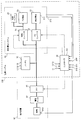
- FIG. 1 is a diagram showing an example of the configuration of a power supply system according to a first embodiment of the present invention.
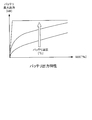
- FIG. 2 is a diagram illustrating the relationship between the temperature of the battery and the output characteristic of the battery.
- FIG. 3 is a diagram for explaining self-heating of the battery.
- FIG. 4 is a diagram illustrating the relationship between the temperature of the fuel cell and the output characteristics of the fuel cell.
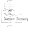
- FIG. 5 is a flow chart showing an example of a processing procedure related to the control method of the power supply system in the present embodiment.
- FIG. 6 is a time chart showing an example of a control method for controlling charge and discharge of the battery with respect to the fuel cell system.
- FIG. 7 is a block showing an example of a functional configuration of a controller that controls the power supply system according to the second embodiment of the present invention.
- FIG. 8 is a block diagram showing an example of a functional configuration of the battery charge processing unit in the present embodiment.
- FIG. 9 is a time chart showing an example of a control method for controlling the power of the fuel cell at the time of charging of the battery in the present embodiment.
- FIG. 10 is a block diagram showing an example of a functional configuration of a battery charge / discharge determination unit constituting the controller in the third embodiment of the present invention.
- FIG. 1 is a block diagram showing an example of the configuration of a power supply system 100 according to the first embodiment of the present invention.
- the power supply system 100 is, for example, a power supply device that supplies power to a load device 90 mounted on a mobile object such as a vehicle, an airplane, or a ship.
- the power supply system 100 in the present embodiment is mounted on a vehicle such as an electric vehicle including a hybrid vehicle or a train.
- vehicle is provided with an accelerator sensor 911, which detects an operation amount of an accelerator pedal by a driver, a brake sensor 912, which detects an operation amount of a brake pedal by the driver, and a vehicle speed sensor 913 which detects the speed of the vehicle.
- the load device 90 is an operating device that operates by extracting power from the power supply system 100.
- the load device 90 according to the present embodiment includes an electric motor 92 for driving a vehicle, and an inverter 91 which converts output power of the power supply system 100 into AC power and supplies the AC power to the electric motor 92.
- the power supply system 100 includes a battery 10, a fuel cell system 20, and a controller 30.
- Power supply system 100 is a hybrid power supply system for supplying power to load device 90 from the power supply of at least one of battery 10 and fuel cell system 20.
- the power supply system 100 includes an FC operation button 200 for the driver to select one of start and stop of the fuel cell system 20, and an outside air temperature sensor 101 disposed on the controller 30 to detect the outside air temperature. Is provided.
- the battery 10 is a power supply that mainly supplies power to the load device 90.
- the battery 10 is connected to both the fuel cell system 20 and the load device 90.
- the battery 10 is realized by a lithium ion battery or a lead battery.
- the battery 10 outputs several hundreds of volts (V) of DC power.
- the battery 10 is provided with a temperature sensor 11, a current sensor 12 and a voltage sensor 13.
- the temperature sensor 11 detects the temperature of the battery 10. Then, the temperature sensor 11 outputs the detected value to the controller 30.
- the current sensor 12 detects the output current of the battery 10. Then, the current sensor 12 outputs the detected value to the controller 30.
- the voltage sensor 13 detects the output voltage of the battery 10. Then, the voltage sensor 13 outputs the detected value to the controller 30.
- the fuel cell system 20 is connected to both the battery 10 and the load device 90.
- the fuel cell system 20 operates so that the fuel cell 21 generates power.
- the fuel cell system 20 includes a fuel cell 21, an FC converter 22, an FC accessory 23, an accessory converter 24, and an auxiliary battery 25.
- the fuel cell 21 is connected to the FC converter 22.
- the fuel cell 21 receives the supply of the fuel gas and the oxidant gas to generate electric power.
- the fuel cell 21 is realized by a solid oxidation fuel cell, a polymer electrolyte fuel cell, or the like.
- the fuel cell 21 of the present embodiment is constituted by a solid oxidation fuel cell.
- the fuel cell 21 is a power supply capable of supplying power to at least one load of the battery 10 and the inverter 91.
- the fuel cell 21 is stacked by a plurality of cells, and outputs voltages of different magnitudes with respect to the output voltage of the battery 10.
- the fuel cell 21 outputs a DC voltage of several tens of volts lower than the output voltage value of the battery 10.
- the fuel cell 21 is used as an auxiliary power supply for assisting the output power of the battery 10.
- Such a power supply system 100 is called a range extender because it has a function of extending the output range of the battery 10.
- the fuel cell 21 is provided with an FC temperature sensor 211, and the fuel cell system 20 is provided with a fuel remaining amount sensor 212.
- the FC temperature sensor 211 detects the temperature of the fuel cell 21.
- the FC temperature sensor 211 detects, for example, the temperature of the fuel cell 21, the temperature of the oxidant gas supplied to the fuel cell 21, or the temperature of the oxidant gas discharged from the fuel cell 21. Then, the FC temperature sensor 211 outputs the detected value to the controller 30.
- the fuel remaining amount sensor 212 detects the remaining amount of fuel supplied to the fuel cell 21. Then, the fuel remaining amount sensor 212 outputs the detected value to the controller 30.
- the FC converter 22 is a voltage conversion device interposed between the battery 10 and the fuel cell 21.
- the FC converter 22 converts the voltage value of the power input from the fuel cell 21 into a different voltage value and outputs it.
- the FC converter 22 is realized by a DC / DC converter that steps up or steps down the input primary side voltage and outputs the secondary side voltage.
- the FC accessory 23 is connected to the accessory converter 24.
- the FC auxiliary device 23 is an accessory device required for the fuel cell 21 to generate power. Examples of the FC auxiliary device 23 include a heater for warming up the fuel cell 21, an actuator for supplying the oxidant gas or the fuel gas to the fuel cell 21, and an actuator for circulating a refrigerant to the fuel cell 21. .
- FC auxiliary device 23 As an example of an actuator which constitutes FC auxiliary machine 23, a blower or a compressor which supplies air from the atmosphere to the fuel cell 21 as an oxidant gas can be mentioned.
- the FC auxiliary device 23 of the present embodiment is configured by a compressor that supplies an oxidant gas to the fuel cell 21.
- the accessory converter 24 is a voltage converter interposed between the battery 10 and the FC accessory 23.
- the accessory converter 24 supplies the output power of at least one of the battery 10 and the fuel cell 21 to the FC accessory 23.
- the accessory converter 24 is realized by a DC / DC converter that converts the voltage between the FC converter 22 and the battery 10 into a voltage value within the operating voltage range of the FC accessory 23.
- Auxiliary battery 25 is interposed between accessory converter 24 and FC accessory 23.
- the auxiliary battery 25 supplies power to the FC auxiliary device 23.
- the auxiliary battery 25 is realized by, for example, a lead battery of several tens of volts.
- the controller 30 is configured by one or more microcomputers provided with a central processing unit (CPU; Central Processing Unit) and a storage device in which predetermined processing is programmed.
- the control device controls the operation of the power supply system 100.
- the controller 30 acquires detection values output from each of the temperature sensor 11, the current sensor 12, the voltage sensor 13, the FC temperature sensor 211, the fuel remaining amount sensor 212, the accelerator sensor 911, the brake sensor 912, and the vehicle speed sensor 913.
- the controller 30 controls the operation of each of the FC converter 22, the accessory converter 24 and the inverter 91 in accordance with the acquired detected values.
- the controller 30 uses the detection value of the accelerator sensor 911 to obtain the required torque required to drive the electric motor 92, and calculates the required power required for the power supply system 100 based on the required torque. Then, the controller 30 controls each of the FC converter 22, the accessory converter 24 and the inverter 91 such that the calculated required power is supplied to the electric motor 92 from at least one of the battery 10 and the fuel cell 21.
- the controller 30 also calculates the charge amount of the battery 10 using the detection value of at least one of the current sensor 12 and the voltage sensor 13 and starts the fuel cell system 20 based on the size of the charge amount.
- the controller 30 of the present embodiment charges the battery 10 with SOC (State Of Charge) obtained from a general calculation method such as current integration or voltage integration of the battery 10 based on detection values of the current sensor 12 and the voltage sensor 13. Calculated as a quantity.
- SOC State Of Charge
- controller 30 controls each of FC converter 22, FC accessory 23 and accessory converter 24 to activate fuel cell system 20 when the calculated SOC of battery 10 falls below a predetermined FC activation threshold. Do.
- the FC stop threshold referred to here may be set to the same value as the above-described FC start threshold, or may be set to a value different from the FC start threshold, for example, a value larger or smaller than the FC start threshold. Good.
- controller 30 executes the start process of the fuel cell system 20. Then, controller 30 controls the operation of accessory converter 24 such that the power discharged from battery 10 is supplied to FC accessory 23.
- FIG. 2 is a diagram illustrating the relationship between the output characteristic of the maximum output of battery 10 with respect to the SOC of battery 10 and the temperature of battery 10.
- the maximum output of the battery 10 is the maximum value of the discharge power of the battery 10.
- the output characteristics of the battery 10 deteriorate as the temperature of the battery 10 decreases.
- the output characteristics of the battery 10 deteriorate because the temperature of the battery 10 is low. Therefore, when the temperature of battery 10 is low, it becomes difficult to take out from battery 10 the required power required to drive load device 90, so it is necessary to warm up battery 10 early.
- FIG. 3 is a circuit diagram illustrating an equivalent circuit of the battery 10.
- the battery 10 has an internal resistance R in addition to the battery body B. Therefore, when discharging the battery 10 to the external device E, since the discharge current flows through the internal resistance R, the internal resistance R generates heat and the battery 10 itself is warmed. Similarly, in the case of charging the battery 10, the charging current flows through the internal resistance R, so the internal resistance R generates heat to warm the battery 10 itself.
- FIG. 4 is a diagram illustrating the relationship between the output characteristics of the voltage with respect to the current of the fuel cell 21 and the temperature of the fuel cell 21. As shown in FIG.
- the output characteristics of the fuel cell 21 also become worse as the temperature of the fuel cell 21 decreases, like the output characteristics of the battery 10.
- a warm-up process is required to raise the temperature of the fuel cell 21 to an operating temperature of several hundred degrees. For this reason, the time required to complete the warm-up of the fuel cell 21 becomes long.
- the controller 30 drives a compressor that constitutes the FC auxiliary machine 23, warms the oxidant gas discharged from the compressor with a combustor, a heater or the like (not shown) and supplies it to the fuel cell 21. Therefore, in order to improve the responsiveness of the fuel cell 21, it is preferable to start the fuel cell system 20 early.
- FIG. 5 is a flowchart showing an example of a processing procedure related to a control method of the power supply system 100 in the present embodiment.
- step S ⁇ b> 10 the controller 30 acquires battery state information for specifying an operating state such as the temperature state of the battery 10 and the input / output power state of the battery 10.
- the battery state information includes a temperature specifying parameter (temperature information) for specifying the temperature Tb of the battery 10, and a charge specifying parameter for specifying the charge state of the battery 10. Further, the battery state information indicates the temperature Tb of the battery 10 specified by the temperature specific parameter, and the presence or absence of the charge state of the battery 10 specified by the charge specific parameter.
- the controller 30 acquires a detection value of the temperature sensor 11 as an example of the temperature specifying parameter.
- an output characteristic map indicating the relationship between the output characteristic of battery 10 and the temperature of battery 10 as shown in FIG. 4 is stored in advance, and if the relationship between the voltage and current of battery 10 is known, the temperature of battery 10 is obtained. It becomes possible to estimate Tb. Therefore, the controller 30 may acquire detection values of each of the current sensor 12 and the voltage sensor 13 as a temperature specifying parameter.
- a heat generation amount map indicating the relationship between the charge / discharge amount of the battery 10 and the heat generation amount of the battery 10 is stored in the controller 30, and the detection value of the outside air temperature sensor 101 at the time of activation of the battery 10 is the temperature Tb of the battery If it is considered, it is possible to estimate the temperature Tb of the battery 10.
- the controller 30 may acquire the detection value of the outside air temperature sensor 101 at the time of activation of the battery 10 and the detection values of the current sensor 12 and the voltage sensor 13 after activation as temperature specific parameters.
- the amount of change in SOC (State Of Charge) of the battery 10 after startup may be used.
- the controller 30 acquires a detection value of the current sensor 12. Then, the controller 30 determines that the battery 10 is in the discharged state when the detection value of the current sensor 12 indicates a positive value, and the battery 10 charges when the detection value of the current sensor 12 indicates a negative value. Judge that it is a state.
- the controller 30 may acquire the torque command value of the electric motor 92 as the charging specific parameter. In such a case, controller 30 determines that electric motor 92 is in the driving state if the torque command value is a positive value, and that electric motor 92 is in the regenerative state if the torque command value is a negative value. to decide.
- the controller 30 may acquire the detection values of each of the current sensor 12 and the voltage sensor 13 and the target value of the generated power of the fuel cell 21 as a charge specific parameter.
- the controller 30 determines the operating state of the battery 10 based on the above-described battery state information.
- step S20 the controller 30 determines whether the temperature Tb of the battery 10 specified by the temperature specifying parameter in the battery state information is equal to or less than the warm-up threshold Tt.
- the warm-up threshold Tt is, for example, a value determined in advance based on the temperature of the battery 10 capable of extracting electric power necessary for driving the electric motor 92 from the battery 10 at the minimum.
- the controller 30 acquires detection values of each of the current sensor 12 and the voltage sensor 13 as temperature specifying parameters, and uses the acquired detection values.
- the discharge power of the battery 10 is calculated.
- the controller 30 refers to the output characteristic map to calculate the temperature related to the discharge power as the temperature Tb of the battery 10.
- controller 30 determines whether battery 10 is at or below a predetermined temperature based on the temperature specific parameter. When the controller 30 determines that the temperature Tb of the battery 10 exceeds the warming-up threshold Tt, the controller 30 ends the control method of the power supply system 100.
- controller 30 determines in step S30 that temperature Tb of battery 10 is equal to or lower than warm-up threshold Tt, the input / output power state of battery 10 is the charge state based on the charge specific parameter in the battery state information. Determine if it is or not.
- the controller 30 determines whether the battery 10 is in a charging state based on the sign of the torque command value. Then, when the torque command value is a positive value, the controller 30 determines that the battery 10 is not in a charging state because the electric motor 92 is in a driving state. On the other hand, when the torque command value is a negative value, the controller 30 determines that the battery 10 is in a charging state because the electric motor 92 is in a regeneration state.
- controller 30 determines in step S41 that battery 10 is not in a charged state, controller 30 controls the operation of accessory converter 24 to discharge battery 10 to FC accessory 23. That is, controller 30 uses the discharge power of battery 10 to output the operation power necessary for the operation of FC accessory 23 from accessory converter 24 to FC accessory 23.
- the controller 30 starts the fuel cell system 20 and discharges the battery 10 to the FC accessory 23. Since the fuel cell 21 of the present embodiment is a solid oxidation fuel cell, the controller 30 executes a warm-up process to raise the temperature of the fuel cell 21 to several hundred degrees in the start-up process of the fuel cell system 20.
- the power generated by the fuel cell 21 may be supplied to the FC accessory 23.
- the controller 30 controls the operation of the FC converter 22 and the accessory converter 24 so that the power supplied to the FC accessory 23 is switched from the generated power of the fuel cell 21 to the discharged power of the battery 10.
- controller 30 determines in step S40 that battery 10 is in the charged state, controller 30 controls the operation of accessory converter 24 to suppress the discharge of battery 10 to FC accessory 23.
- controller 30 controls accessory converter 24 so that the output power from battery 10 to FC accessory 23 is smaller than the operating power of FC accessory 23 by a predetermined power. Decrease to the value.
- the controller 30 stops outputting power from the accessory converter 24 to the FC accessory 23.
- the controller 30 boosts the output side voltage value of the accessory converter 24 more than the voltage value of the operating power to be supplied to the FC accessory 23.
- the auxiliary battery 25 is connected between the FC auxiliary machine 23 and the auxiliary machine converter 24, the power corresponding to the reduction of the output power of the auxiliary machine converter 24 is transmitted from the auxiliary battery 25 to the FC auxiliary machine 23. Taken out.
- step S40 or S41 ends, a series of processing procedures regarding the control method of the power supply system 100 end.
- the controller 30 determines whether the battery 10 is in the charging state based on the above-described charge specifying parameter. Decide whether or not. Then, when the controller 30 determines that the battery 10 is in a charged state, the controller 30 reduces or stops the power supplied from the battery 10 to the FC accessory 23.
- controller 30 sets the output power output from accessory converter 24 to FC accessory 23 as the operating power at which FC accessory 23 operates. adjust. Furthermore, when controller 30 determines that battery 10 is in a charged state, controller 30 sets the output power of accessory converter 24 to a value smaller than the operating power.
- step S30 is performed after the process of step S20 is performed in FIG. 5, the processes of steps S20 and S30 may be performed in parallel.
- FIG. 6 is a time chart showing an example of a power control method of the battery 10 and the fuel cell system 20 when the temperature Tb of the battery 10 is lower than the warm-up threshold Tt.
- the horizontal axis indicates time
- the vertical axis indicates charging power and discharging power of the battery 10.
- the INV power represents the positive drive power from battery 10 to inverter 91 and the negative regenerative power from electric motor 92 to inverter 91
- the FC auxiliary power is from battery 10 through FC converter 24 via FC converter Represents the power discharged to the machine 23.
- the battery input / output power represents a change in total charge power and discharge power in the battery 10.
- the controller 30 determines that the temperature Tb of the battery 10 is lower than the warm-up threshold Tt, and executes the process of activating the fuel cell system 20. Since the fuel cell 21 of this embodiment is a solid oxidation fuel cell, the start-up process of the fuel cell system 20 includes a warm-up process for raising the temperature of the fuel cell 21 to a temperature suitable for power generation.
- the controller 30 supplies power from the battery 10 to the electric motor 92 via the inverter 91.
- the controller 30 controls the FC converter 22 to supply power from the battery 10 to the inverter 91, and controls the accessory converter 24 to discharge the battery 10 to the FC accessory 23.
- the power supply system 100 can improve the output characteristics of the battery 10 at an early stage, and can efficiently perform the warm-up process of the fuel cell system 20.
- the controller 30 determines that the battery 10 is in a charged state. Then, the controller 30 stops the power supplied from the battery 10 to the FC accessory 23 via the accessory converter 24. Therefore, the FC auxiliary machine power is 0 (zero).
- the warm-up of the battery 10 can be promoted when the battery 10 is discharged.
- the battery 10 is discharged to the FC auxiliary machine 23 until the battery 10 transitions to the charged state, whereby the output of the battery 10 is efficiently output. Properties can be improved.
- the power supply system 100 includes a fuel cell system 20 having an FC accessory 23 operated to generate power by the fuel cell 21 and a battery 10 generating heat by discharge and charge, Power is supplied to the load device 90.
- the control method of the power supply system 100 described above includes steps S20 and S30 for determining the operating state of the battery 10, and an FC accessory by discharging the battery 10 when it is determined that the temperature of the battery 10 is lower than a predetermined temperature in step S20. And S23 of supplying power to S.23.
- the control method of power supply system 100 includes step S40 of reducing or stopping the power supplied to FC auxiliary device 23 in step S41 when it is determined in step S30 that battery 10 is in a charging state.
- the discharge current flowing to the internal resistance R of the battery 10 increases. Warming up of the battery 10 can be promoted. Furthermore, since the discharge power of battery 10 is effectively utilized in the warm-up process of fuel cell system 20, the consumed power of power from fuel cell 21 and the power of auxiliary battery 25 by the amount of the power discharged from battery 10 is consumed. Can be reduced. Therefore, it is possible to suppress an increase in energy loss in fuel cell system 20 while promoting the warm-up of both battery 10 and fuel cell 21.
- the power supplied from the battery 10 to the FC accessory 23 is reduced or stopped when the battery 10 transitions to the charge state.
- a decrease in the charging power of the battery 10 can be suppressed, so that it is possible to suppress a decrease in the self-heating amount of the battery 10 while suppressing wasteful discharge from the battery 10 to the FC accessory 23.
- the output characteristics of the power supply system 100 can be promptly improved while suppressing the decrease in the temperature rising effect due to the discharge of the battery 10. That is, the output characteristics of the battery 10 can be improved efficiently.
- power supply system 100 further includes an auxiliary battery 25 connected to FC auxiliary device 23.
- the controller 30 determines that the battery 10 is in the charged state as described in step S40 of FIG. 5, the controller 30 supplies power from the auxiliary battery 25 to the FC auxiliary device 23 to operate the FC auxiliary device 23.
- power supply system 100 further includes an accessory converter 24 interposed between battery 10 and FC accessory 23.
- the accessory converter 24 steps down the voltage of the FC accessory 23 from the voltage of the battery 10. Then, when controller 30 determines that battery 10 is in a charged state, controller 30 reduces or stops the output power output from accessory converter 24 to FC accessory 23.
- the controller 30 controls the output power of the accessory converter 24 to reduce the power supplied from the battery 10 to the FC accessory 23. Furthermore, as shown in FIG. 1, the auxiliary battery 25 is directly connected to the FC auxiliary machine 23, and no power loss occurs in the auxiliary machine converter 24. Therefore, the power is efficiently supplied to the FC auxiliary machine 23. Can.
- the controller 30 in the present embodiment controls the FC converter 22 and the accessory converter 24 to supply power from the fuel cell 21 to the FC accessory 23.
- the FC auxiliary machine 23 can be operated while suppressing the power supply from the battery 10 to the FC auxiliary machine 23.
- the controller 30 supplies the generated power of the fuel cell 21 to the FC auxiliary machine 23. Therefore, the FC auxiliary machine 23 does not have to be stopped. Therefore, the fuel cell 21 is efficiently warmed up. The warm-up of can be continued. Therefore, warm-up of both the battery 10 and the fuel cell 21 can be completed early.
- the battery 10 may supply power to the FC accessory 23 to operate the FC accessory 23.
- the controller 30 supplies power from the battery 10 to the FC accessory 23.
- the controller 30 may supply power from the battery 10 to the FC accessory 23. Supply.
- the controller 30 supplies power from the battery 10 to the FC accessory 23 without suppressing the discharge of the battery 10 when it is preferable to prioritize the warm-up of the fuel cell 21 over the warm-up of the battery 10. Do.
- power can be continuously supplied from the power supply system 100 to the load device 90.
- the load device 90 includes the electric motor 92 having the drive state and the regeneration state. Then, as described in steps S10 and S30 shown in FIG. 5, the controller 30 determines that the battery 10 is in the charging state when the electric motor 92 shifts to the regeneration state. For example, the controller 30 determines whether the electric motor 92 has transitioned to the regeneration state based on the sign of the torque command value of the electric motor 92 or the sign of the current value of the electric motor 92. As described above, when the controller 30 detects or estimates the operating state of the electric motor 92, it can be determined whether the battery 10 is in a charged state.
- controller 30 detects the current of battery 10 using current sensor 12, and if the value of the detected current indicates the charging current, it is assumed that battery 10 is in the charging state. It may be determined. In the present embodiment, the charging current when the battery 10 is charged shows a negative value.
- the controller 30 uses the current sensor 12, the operating state of the battery 10 can be accurately determined. Therefore, even if the battery 10 is switched from the discharged state to the charged state, the period in which the discharging of the battery 10 to the FC accessory 23 continues can be shortened.
- the fuel cell 21 is constituted by the solid oxidation fuel cell
- the controller 30 is the solid oxidation type when the fuel cell system 20 is started as described in step S41 of FIG. Warm up the fuel cell.
- a solid oxidation fuel cell needs to raise its temperature to several hundred degrees. Therefore, it takes a specific time, for example, several tens of minutes, to finish the warm-up of the solid oxidation fuel cell.
- the solid oxidation fuel cell As described above, it takes time to warm up the fuel cell 21, and the responsiveness of the fuel cell 21 is deteriorated. Therefore, the responsiveness of the power supply system 100 can be improved by promoting the warm-up of the battery 10 even when the battery 10 is in a charged state.
- the controller 30 ends the warm-up of the fuel cell 21.
- a specific temperature for example, 600 ° C. or more
- the controller 30 ends the warm-up of the fuel cell 21.
- the fuel cell 21 can charge the battery 10 with the generated power via the FC converter 22. Therefore, the charge power of the battery 10 is increased. Can promote warm-up.
- FIG. 7 is a block diagram showing an example of the main functional configuration of the controller 30 in the second embodiment of the present invention.
- the controller 30 includes a warm-up determination unit 310, a charge / discharge determination unit 320, a battery discharge processing unit 330, a battery charge processing unit 340, a process switching unit 350, and an operation command unit 360.
- Warmup determination unit 310 determines the temperature state of battery 10. As described in step S20 of FIG. 5, the warm-up determination unit 310 determines whether the temperature Tb of the battery 10 is equal to or lower than the warm-up threshold Tt using the temperature specific parameter of the battery 10.
- a detection value of the temperature sensor 11 As a temperature specific parameter of the battery 10, for example, a detection value of the temperature sensor 11, each detection value of the current sensor 12 and the voltage sensor 13, etc. may be mentioned.
- the detection value of the FC temperature sensor 211 or the detection value of the outside air temperature sensor may be used as a temperature specific parameter of the battery 10.
- Warm-up determination unit 310 outputs a warm-up command signal indicating that battery 10 needs to be warmed up to charge / discharge determination unit 320 when temperature Tb of battery 10 is equal to or lower than warm-up threshold Tt. .
- warm-up determination unit 310 outputs a normal command signal indicating that warm-up of battery 10 is not necessary to charge / discharge determination unit 320.
- the charge / discharge determination unit 320 determines the power state of the battery 10. As described in step S30 of FIG. 5, the charge / discharge determination unit 320 determines whether the power state of the battery 10 is the charge state using the charge specific parameter of the battery 10.
- a charge specific parameter of the battery 10 for example, a detected value of at least one of the current sensor 12 and the voltage sensor 13, or a torque command value output from the operation command unit 360 to the inverter 91 can be mentioned.
- the charge / discharge determination unit 320 may have hysteresis so that the determination result is not frequently switched in a short time.
- the charge / discharge determination unit 320 When it is determined that the battery 10 is in a charging state, the charge / discharge determination unit 320 outputs a charge control signal indicating charging of the battery 10 to the process switching unit 350. On the other hand, when determining that the battery 10 is not in a charged state, the charge / discharge determination unit 320 outputs a discharge control signal indicating discharge of the battery 10 to the process switching unit 350.
- Battery discharge processing unit 330 controls accessory converter 24 to discharge battery 10 to FC accessory 23. Specifically, based on the detection value of the accelerator sensor 911, the battery discharge processing unit 330 generates a torque command value indicating the regenerative force and the driving force of the electric motor 92, a power generation command value indicating the generated power of the fuel cell 21, FC An accessory operation command value for driving the accessory 23 is calculated.
- the FC auxiliary machine 23 in the present embodiment is a compressor for supplying the oxidant gas to the fuel cell 21, the battery charge processor 340 sets the torque command value of the drive motor provided in the compressor as the above-mentioned auxiliary machine operation command value.
- the battery discharge processing unit 330 outputs the calculated torque command value of the electric motor 92, the power generation command value of the fuel cell 21, and the accessory operation command value of the FC accessory 23 to the processing switching unit 350.
- the battery charge processing unit 340 controls the accessory converter 24 to suppress the power supplied to the FC accessory 23. Specifically, based on the detection value of accelerator sensor 911, battery charge processor 340 calculates the torque command value of electric motor 92, the power generation command value of fuel cell 21, and the auxiliary machine operation command value of FC auxiliary machine 23. Do. The battery discharge processing unit 330 outputs the calculation result to the process switching unit 350.
- process switching unit 350 When receiving the discharge control signal from charge / discharge determination unit 320, process switching unit 350 outputs the calculation result of battery discharge processing unit 330 to operation command unit 360. On the other hand, when receiving the charge control signal from charge / discharge determination unit 320, process switching unit 350 outputs the calculation result of battery charge processing unit 340 to operation command unit 360.
- Operation command unit 360 supplies a torque command value of electric motor 92 to inverter 91, supplies a power generation command value of fuel cell 21 to FC converter 22, and supplies an operation command value of FC accessory 23 to accessory converter 24.
- FIG. 8 is a block diagram showing an example of a functional configuration of the battery charge processing unit 340 in the present embodiment.
- the battery charge processing unit 340 includes a motor request torque calculation unit 341, a torque / power conversion unit 342, a battery limited charge amount calculation unit 343, a regenerative power setting unit 344, and a power / torque conversion unit 361. Furthermore, battery charge processing unit 340 includes surplus charge amount calculation unit 345, lower limit setting unit 346, chargeable power setting unit 347, FC upper limit power generation amount calculation unit 348, generated power setting unit 349, and FC auxiliary machine command. A computing unit 362 and an FC power generation command computing unit 363 are provided.
- the motor required torque calculation unit 341 calculates a motor required torque necessary for driving the electric motor 92 using the detection values of the accelerator sensor 911, the brake sensor 912, and the vehicle speed sensor 913.
- the required motor torque becomes larger than 0 as the operation amount of the accelerator pedal becomes larger, and the required motor torque becomes smaller as the vehicle speed becomes larger.
- the driving force of the electric motor 92 increases and decreases.
- the motor request torque becomes smaller than zero.
- the regenerative torque of the electric motor 92 is increased by the increase of the motor request torque on the negative side.
- a predetermined required torque map generally used is stored in advance in the motor required torque calculation unit 341 of the present embodiment.
- set values of the required motor torque are associated with each operating point specified by the operation amount of the accelerator pedal, the operation amount of the brake pedal, and the vehicle speed.
- the request torque map is referenced to be associated with the operating point specified by these detection values. Calculate the set value of the required motor torque.
- the motor required torque calculation unit 341 may calculate the motor required torque by applying the detection values of the accelerator sensor 911, the brake sensor 912, and the vehicle speed sensor 913 to a commonly used predetermined arithmetic expression. You may
- the torque / power conversion unit 342 converts the calculation result into the motor required power based on the calculation result of the motor required torque calculation unit 341.
- the motor required power is a parameter indicating the magnitude of the drive power required to drive the electric motor 92 and the magnitude of the regenerated power generated by the regeneration of the electric motor 92.
- the motor required power shows a positive value
- the motor required power shows a negative value
- the required motor power increases on the negative side, that is, on the regeneration side.
- the torque / power conversion unit 342 applies the detection result of the motor required torque calculation unit 341 and the detection value of the vehicle speed sensor 913 to a general predetermined arithmetic expression or a predetermined map to calculate the motor required power.
- the battery limited charge amount computation unit 343 computes the charge lower limit value indicating the limit value of the charging power regarding the battery 10, as shown in FIG.
- the charge lower limit value is a negative value.
- the lower the temperature of the battery 10 the worse the discharge characteristics of the battery 10, so the upper limit value of the discharge power, which is the maximum output of the battery 10, becomes lower.
- the lower the temperature of the battery 10 the worse the charge characteristics of the battery 10, and the higher the charge lower limit value of the battery 10 becomes.
- the battery limited charge amount computation unit 343 in the present embodiment calculates the charge lower limit value of the battery 10 based on the detection value of the temperature sensor 11. For example, the battery limited charge amount computation unit 343 The lower limit charge amount map in which the setting value of the charge lower limit is associated with each temperature is stored in advance.
- the battery limited charge amount calculation unit 343 calculates the setting value associated with the detection value of the temperature sensor 11 as the charge lower limit value with reference to the lower limit charge amount map.
- the battery limited charge amount calculation unit 343 may correct the charge lower limit value in accordance with the SOC of the battery 10. For example, the battery limited charge amount computation unit 343 increases the charge lower limit value as the SOC of the battery 10 increases.
- the detection value of the temperature sensor 11 was used as a temperature of the battery 10, you may use the estimated value of the temperature of the battery 10 obtained by the above-mentioned temperature specific parameter.
- Regenerative power setting unit 344 sets the larger one of the motor request power from torque / power conversion unit 342 and the charge lower limit value from battery restricted charge amount computation unit 343 as the target regenerative power of electric motor 92.
- the target regenerative power is a parameter indicating a target value of the regenerative power of the electric motor 92.
- the surplus charge amount calculation unit 345 acquires the motor request power from the torque / power conversion unit 342 as the regenerative power charged from the electric motor 92 to the battery 10. Then, the surplus charge amount calculation unit 345 is capable of surplus charge indicating the upper limit value of the chargeable power other than the regenerative power from the electric motor 92 by subtracting the charge lower limit value from the acquired motor request power. Calculate the power.
- the lower limit setting unit 346 sets “0” as the lower limit value of the surplus chargeable power in order to prevent the surplus chargeable power from becoming a value smaller than zero.
- the chargeable power setting unit 347 newly sets the larger value of the surplus chargeable power and the lower limit value thereof as the surplus chargeable power.
- the FC upper limit power generation amount computing unit 348 calculates a power generation upper limit value indicating the upper limit value of the generated power of the fuel cell 21 so as to avoid the performance deterioration due to the excessive power generation of the fuel cell 21.
- the power generation upper limit value may be previously determined in consideration of experimental data or simulation results or may be changed according to the temperature of the fuel cell 21.
- the generated power setting unit 349 sets the smaller one of the surplus chargeable power of the battery 10 and the power generation upper limit value of the fuel cell 21 as a target generated power indicating a target value of the generated power of the fuel cell 21.
- the electric power / torque conversion unit 361 converts the target regenerative power into a torque command value of the electric motor 92 based on the target regenerative power from the regenerative power setting unit 344.
- the electric power / torque conversion unit 361 of the present embodiment applies the target regenerative electric power and the detection value of the vehicle speed sensor 913 to a predetermined arithmetic expression or a predetermined map to calculate a torque command value of the electric motor 92. As the target regenerative power increases, the torque command value increases on the negative side, and as the vehicle speed increases, the torque command value decreases on the negative side. The electric power / torque conversion unit 361 outputs the calculated torque command value to the inverter 91.
- the FC accessory command computation unit 362 computes an accessory operation command value indicating the value of the operation power required for the operation of the FC accessory 23 based on the target generated power from the generated power setting unit 349. For example, since the amount of air required for the fuel cell 21 to generate power increases as the target generated power increases, the accessory operation command value increases.
- the FC accessory command calculation unit 362 supplies the above-described accessory operation command value to the accessory converter 24.
- the FC power generation command computation unit 363 computes a power generation command value indicating the value of the power to be taken out from the fuel cell 21 based on the target generated power from the generated power setting unit 349. For example, as the target generated power increases, the power generation command value of the fuel cell 21 increases.
- the FC power generation command computation unit 363 outputs the power generation command value to the FC converter 22.
- the surplus charge amount calculation unit 345 calculates the generated power of the fuel cell 21 capable of charging the battery 10 in addition to the regenerative power of the electric motor 92. As a result, it is possible to increase the amount of power generation of the fuel cell 21 so that the power charged in the battery 10 reaches the charging lower limit value without supplying power from the battery 10 to the FC auxiliary device 23 .
- FIG. 9 is a time chart showing an example of a power control method of the battery 10 and the fuel cell 21 when the battery 10 transitions to the charge state.
- FIG. 9 shows, in addition to the battery input / output power and the INV power shown in FIG. 6, an FC power generation amount indicating the magnitude of the generated power of the fuel cell 21 charged to the battery 10.
- warm-up determination unit 310 determines that temperature Tb of battery 10 is lower than warm-up threshold Tt. Further, since the controller 30 executes the start-up process of the fuel cell system 20, the temperature of the fuel cell 21 has risen to the above-described normal operation threshold value, so the warm-up of the fuel cell 21 is completed.
- the controller 30 controls the FC converter 22 and the accessory converter 24 to supply power from the fuel cell 21 to the FC accessory 23. Therefore, the battery 10 is not discharged to the FC accessory 23.
- the charge / discharge determination unit 320 determines that the battery 10 is in the discharged state. In this period, the temperature of the fuel cell 21 rises to a specific normal operation threshold value, for example, about 600 ° C., and the warm-up process of the fuel cell 21 is finished.
- the charge / discharge determination unit 320 determines that the battery 10 is in a charging state. Therefore, the battery charge processing unit 340 sets the target generated power of the fuel cell 21 in the range not exceeding the power generation upper limit value of the fuel cell 21 among the surplus chargeable power of the battery 10. In this example, the target generated power is set to the power generation upper limit value.
- the regenerative electric power of the electric motor 92 increases with an increase in the operation amount of the brake pedal, and the reduction rate of the INV electric power further increases.
- the battery input / output power indicating the charging power of the battery 10 reaches the charging lower limit value as the rate of decrease of the INV power increases. Then, in the battery charge processing unit 340 shown in FIG. 8, since the surplus chargeable power set by the chargeable power setting unit 347 is lower than the power generation upper limit value, the target generated power is set to the surplus chargeable power. Since the excess chargeable power changes in accordance with the increase or decrease of the motor required power, as shown in FIG. 9, the FC power generation amount decreases as the INV power corresponding to the motor required power decreases.
- the INV power sharply changes from a negative value to a positive value.
- the battery charge processor 340 charges the battery 10 with the generated power of the fuel cell 21 when the battery 10 transitions to the charge state. As a result, the charging power of the battery 10 is increased, so the warm-up of the battery 10 can be promoted.
- the battery charge processing unit 340 generates the FC power when the battery input / output power reaches the charge lower limit The power generation of the fuel cell 21 may be stopped so that the power becomes zero. Thereby, it is possible to suppress a situation where the battery input / output power exceeds the charging lower limit value due to the abrupt change of the INV power.
- the battery charge processor 340 has finished warming up the fuel cell 21 when it is determined that the battery 10 is in the charged state. At the time, the battery 10 is charged using the power generated by the fuel cell 21. As a result, the current flowing to the battery 10 is increased when the battery 10 transitions to the charge state, so the warm-up of the battery 10 can be promoted.
- the battery limited charge amount calculation unit 343 shown in FIG. 8 obtains the limit value of the charging power of the battery 10 based on the temperature of the battery 10. Then, using the chargeable power setting unit 347, the generated power setting unit 349 reduces or stops the generated power of the fuel cell 21 so that the charge power of the battery 10 does not exceed the limit value. This makes it possible to prevent the charging power of the battery 10 from exceeding the limit value, and it is possible to suppress the deterioration of the battery 10 due to the overcharging of the battery 10.
- FIG. 10 is a block diagram showing an example of a functional configuration of the charge / discharge determination unit 320 in the third embodiment of the present invention.
- the charge / discharge determination unit 320 of this embodiment compares the battery charge power calculation unit 321, the FC auxiliary power consumption calculation unit 322, the FC generated power calculation unit 323, the calculation unit 324, the threshold setting unit 325, and the like. And a unit 326.
- the battery charge power calculation unit 321 calculates charge power of the battery 10 based on detection values of the current sensor 12 and the voltage sensor 13 of the battery 10.
- the calculated value of the charging power indicates a positive value when the battery 10 is in the charging state.
- the battery charge power calculation unit 321 calculates the charge power of the battery 10 by multiplying the detection value of the current sensor 12 by the detection value of the voltage sensor 13.
- the FC auxiliary machine power consumption calculation unit 322 calculates the power consumption of the FC auxiliary machine 23 based on the auxiliary machine operation command value from the FC auxiliary machine command calculation unit 362. For example, when the accessory operation command value is a compressor torque command value, the FC accessory power consumption calculation unit 322 uses the compressor torque command value and the compressor rotation speed to calculate the power consumption of the FC accessory 23. calculate.
- the FC auxiliary machine power consumption calculation unit 322 calculates a value obtained by adding the output of the heater to the power consumption of the compressor. It may be calculated as the power consumption of the device 23.
- the FC generated power calculation unit 323 calculates the generated power of the fuel cell 21 based on the power generation command value from the FC power generation command calculation unit 363. For example, when the power generation command value indicates the fuel cell side voltage value of the FC converter 22 required to take out the target generated power of the fuel cell 21, the FC generated power calculation unit 323 determines from the fuel cell side voltage the fuel cell Calculate the power generation of 21.
- the FC generated power calculating unit 323 may acquire the target generated power from the generated power setting unit 349 illustrated in FIG. 8 and output the acquired value to the calculating unit 324.
- the calculation unit 324 calculates the power consumption of the fuel cell system 20 by subtracting the power consumption from the FC accessory power consumption calculation unit 322 from the power generation of the fuel cell 21 acquired from the FC generated power calculation unit 323. Then, the calculation unit 324 adds the power consumption of the fuel cell system 20 and the charge power from the battery charge power calculation unit 321.
- the threshold setting unit 325 sets “0” as a determination threshold for determining whether the charge power of the battery 10 exceeds the power consumption of the fuel cell system 20.
- the comparison unit 326 compares the calculation result of the calculation unit 324 with the determination threshold. That is, the comparison unit 326 determines whether the charging power of the battery 10 exceeds the power consumption of the fuel cell system 20.
- the comparing unit 326 determines that the battery 10 transitions to the charging state, and outputs “1” as the determination result.
- comparing section 326 determines that battery 10 does not transition to the charging state, and outputs “0” as the determination result.
- the charge / discharge determination unit 320 compares the detected value of the charge power of the battery 10 with the predicted value of the power consumption of the fuel cell system 20 in advance to determine whether the battery 10 transitions to the charge state Can be judged.
- comparison unit 326 may have hysteresis so that the determination result does not frequently switch in a short time when the calculation result of the calculation unit 324 fluctuates near zero.
- charge / discharge determination unit 320 charges battery 10 using the detected value of the current of battery 10 and the detected value of the voltage of battery 10. Calculate the power. Further, charge / discharge determination unit 320 calculates the power consumption of fuel cell system 20 using the power generation command value of fuel cell 21 and the operation command value of FC auxiliary device 23. Then, when the charge power of battery 10 exceeds the power consumption of fuel cell system 20, charge / discharge determination unit 320 determines that battery 10 is in a charge state.
- charge / discharge determination unit 320 monitors only the detected value of the charging power of battery 10, battery input / output power at time t1 in FIG. 6 even though INV power has reached “0”. Since it has not reached "0", it is not determined that the battery 10 is in a charged state. As a result, the supply of FC auxiliary power due to the discharge of the battery 10 is not stopped.
- the charge / discharge determination unit 320 compares the detected value of the charging power of the battery 10 with the predicted value of the power consumption based on the command value of the fuel cell system 20. It is possible to accurately determine transition to the charge state. For this reason, although the electric motor 92 is in the regenerative state, discharging the battery 10 to the FC auxiliary machine 23 can suppress the inhibition of the warm-up of the battery 10.
- the blower or compressor for supplying air to the fuel cell 21 is the FC auxiliary device 23 in the above embodiment
- the present invention is not limited to this.
- the FC auxiliary device 23 may be a blower that supplies ethanol or the like used for power generation of a solid oxidation fuel cell, or may be a pump that supplies a refrigerant to the fuel cell 21. Even with such a device, it is possible to obtain the same effects as those of the above embodiment.
Landscapes
- Engineering & Computer Science (AREA)
- Power Engineering (AREA)
- Life Sciences & Earth Sciences (AREA)
- Sustainable Energy (AREA)
- Sustainable Development (AREA)
- Chemical Kinetics & Catalysis (AREA)
- General Chemical & Material Sciences (AREA)
- Electrochemistry (AREA)
- Chemical & Material Sciences (AREA)
- Manufacturing & Machinery (AREA)
- Transportation (AREA)
- Mechanical Engineering (AREA)
- Physics & Mathematics (AREA)
- General Physics & Mathematics (AREA)
- Fuel Cell (AREA)
- Secondary Cells (AREA)
- Charge And Discharge Circuits For Batteries Or The Like (AREA)
- Electric Propulsion And Braking For Vehicles (AREA)
Abstract
Description
図1は、本発明の第1実施形態における電源システム100の構成の一例を示す構成図である。
図7は、本発明の第2実施形態におけるコントローラ30の主要な機能構成の一例を示すブロック図である。
図10は、本発明の第3実施形態における充電/放電判断部320の機能構成の一例を示すブロック図である。
Claims (13)
- 燃料電池が発電するように作動する補機を有する燃料電池システムと、放電及び充電によって発熱するバッテリとを備え、負荷に電力を供給する電源システムの制御方法であって、
前記バッテリの動作状態を判断する判断ステップと、
前記判断ステップにおいて前記バッテリが所定温度以下であると判断された場合には、前記バッテリの放電により前記燃料電池システムの前記補機に電力を供給する放電ステップと、
前記判断ステップにおいて前記バッテリが充電状態であると判断された場合には、前記放電ステップにおいて前記補機に供給される電力を減少又は停止させる充電制御ステップと、
を含む電源システムの制御方法。 - 請求項1に記載の電源システムの制御方法であって、
前記電源システムは、前記補機に接続される補助バッテリをさらに含み、
前記充電制御ステップは、前記バッテリが充電状態であると判断された場合には、前記補助バッテリから前記補機に電力を供給して前記補機を作動させる、
電源システムの制御方法。 - 請求項2に記載の電源システムの制御方法であって、
前記電源システムは、前記バッテリと前記補機との間に介装され、前記補機の電圧を前記バッテリの電圧から降圧するコンバータをさらに含み、
前記充電制御ステップは、前記バッテリが充電状態であると判断された場合には、前記コンバータから前記補機に出力される出力電力を減少又は停止させる、
電源システムの制御方法。 - 請求項1に記載の電源システムの制御方法であって、
前記充電制御ステップは、前記バッテリが充電状態であると判断された場合には、前記燃料電池から前記補機に電力を供給して前記補機を作動させる、
電源システムの制御方法。 - 請求項1に記載の電源システムの制御方法であって、
前記充電制御ステップは、前記バッテリが充電状態であると判断された場合には、前記バッテリから前記補機に電力を供給して前記補機を作動させる、
電源システムの制御方法。 - 請求項1から請求項5までのいずれか1項に記載の電源システムの制御方法であって、
前記充電制御ステップは、前記バッテリが充電状態であると判断された場合において、前記燃料電池の暖機が終了しているときには、前記燃料電池の発電電力を用いて前記バッテリを充電する、
電源システムの制御方法。 - 請求項6に記載の電源システムの制御方法であって、
前記充電制御ステップは、
前記バッテリの温度に基づいて前記バッテリに関する充電電力の制限値を求め、
前記バッテリの充電電力が前記制限値を超えないよう前記燃料電池の発電電力を減少又は停止させる、
電源システムの制御方法。 - 請求項1から請求項7までのいずれか1項に記載の電源システムの制御方法であって、
前記負荷は、駆動状態及び回生状態を有する電動モータを含み、
前記判断ステップは、前記電動モータが回生状態に遷移した場合に、前記バッテリが充電状態であると判断する、
電源システムの制御方法。 - 請求項1から請求項7までのいずれか1項に記載の電源システムの制御方法であって、
前記判断ステップは、
前記バッテリの電流を検出し、
前記検出した電流値の符号が前記バッテリの充電電流を示す場合には、前記バッテリが充電状態であると判断する、
電源システムの制御方法。 - 請求項1から請求項7までのいずれか1項に記載の電源システムの制御方法であって、
前記判断ステップは、
前記バッテリの電流及び電圧の各検出値に基づいて前記バッテリの充電電力を算出し、
前記燃料電池の発電指令値及び前記補機の作動指令値に基づいて前記燃料電池システムの消費電力を算出し、
前記バッテリの充電電力が前記燃料電池システムの消費電力を上回る場合に、前記バッテリが充電状態であると判断する、
電源システムの制御方法。 - 請求項1から請求項10までのいずれか1項に記載の電源システムの制御方法であって、
前記燃料電池は、固体酸化型燃料電池であり、
前記燃料電池システムを起動する場合には、前記固体酸化型燃料電池を暖機する暖機ステップをさらに含む電源システムの制御方法。 - 請求項11に記載の電源システムの制御方法であって、
前記暖機ステップは、前記燃料電池が特定温度以上になった場合に、前記燃料電池の暖機を終了する、
電源システムの制御方法。 - 燃料電池が発電するように作動する補機を含む燃料電池システム及びバッテリを備え、負荷に電力を供給する電源システムであって、
前記バッテリと前記補機との間に介装されるコンバータと、
前記バッテリの温度が所定値以下であると判断した場合には、前記コンバータから前記補機への出力電力を前記補機が作動する作動電力に調整するコントローラと、を含み、
前記コントローラは、前記バッテリが充電状態であると判断した場合には、前記コンバータの前記出力電力を前記作動電力よりも小さな値に設定する、
電源システム。
Priority Applications (5)
| Application Number | Priority Date | Filing Date | Title |
|---|---|---|---|
| CN201780093388.6A CN110945696B (zh) | 2017-07-31 | 2017-07-31 | 电源系统及其控制方法 |
| EP17920297.3A EP3664205A4 (en) | 2017-07-31 | 2017-07-31 | POWER SUPPLY SYSTEM AND RELATED CONTROL PROCEDURE |
| JP2019533755A JP6888679B2 (ja) | 2017-07-31 | 2017-07-31 | 電源システム及びその制御方法 |
| PCT/JP2017/027760 WO2019026149A1 (ja) | 2017-07-31 | 2017-07-31 | 電源システム及びその制御方法 |
| US16/632,598 US10998748B2 (en) | 2017-07-31 | 2017-07-31 | Electric power supply system and control method therefor |
Applications Claiming Priority (1)
| Application Number | Priority Date | Filing Date | Title |
|---|---|---|---|
| PCT/JP2017/027760 WO2019026149A1 (ja) | 2017-07-31 | 2017-07-31 | 電源システム及びその制御方法 |
Publications (1)
| Publication Number | Publication Date |
|---|---|
| WO2019026149A1 true WO2019026149A1 (ja) | 2019-02-07 |
Family
ID=65233441
Family Applications (1)
| Application Number | Title | Priority Date | Filing Date |
|---|---|---|---|
| PCT/JP2017/027760 Ceased WO2019026149A1 (ja) | 2017-07-31 | 2017-07-31 | 電源システム及びその制御方法 |
Country Status (5)
| Country | Link |
|---|---|
| US (1) | US10998748B2 (ja) |
| EP (1) | EP3664205A4 (ja) |
| JP (1) | JP6888679B2 (ja) |
| CN (1) | CN110945696B (ja) |
| WO (1) | WO2019026149A1 (ja) |
Cited By (2)
| Publication number | Priority date | Publication date | Assignee | Title |
|---|---|---|---|---|
| KR20210145280A (ko) * | 2019-04-18 | 2021-12-01 | 에.게오 렉스 게엠베하 | 전기 구동 모터 차량의 차량 전기 시스템을 위한 회로 장치 및 상기 유형의 회로 장치를 작동하는 방법 |
| JP2023150507A (ja) * | 2022-03-31 | 2023-10-16 | パナソニックIpマネジメント株式会社 | 燃料電池と二次電池とを有する電源システム及びその運転方法 |
Families Citing this family (10)
| Publication number | Priority date | Publication date | Assignee | Title |
|---|---|---|---|---|
| US20210362608A1 (en) * | 2018-10-17 | 2021-11-25 | Aisin Corporation | Vehicle drive device |
| TWI691142B (zh) * | 2019-06-20 | 2020-04-11 | 廣達電腦股份有限公司 | 智慧電池裝置及充電方法 |
| US12057561B1 (en) | 2019-07-12 | 2024-08-06 | Ampcera Inc. | Systems and methods for induction heating of electrolytes |
| US20220247015A1 (en) * | 2019-07-12 | 2022-08-04 | Ampcera Inc. | Interally heatable battery, internally heatable battery system, internally heatable battery method, and electric vehicle comprising the same |
| JP7223043B2 (ja) * | 2021-01-27 | 2023-02-15 | 本田技研工業株式会社 | 電力供給システムおよび電力供給方法 |
| JP7299263B2 (ja) * | 2021-03-26 | 2023-06-27 | 本田技研工業株式会社 | 電力制御システム |
| KR20220162514A (ko) * | 2021-06-01 | 2022-12-08 | 현대자동차주식회사 | 모빌리티의 연료전지 시스템 및 제어방법 |
| KR20230033281A (ko) * | 2021-09-01 | 2023-03-08 | 현대자동차주식회사 | 연료전지 운전제어기 및 운전제어방법 |
| KR20230075605A (ko) * | 2021-11-23 | 2023-05-31 | 현대자동차주식회사 | 발전용 연료전지 시스템 및 그 제어방법 |
| CN115593277B (zh) * | 2022-10-19 | 2024-10-01 | 重庆长安新能源汽车科技有限公司 | 磷酸铁锂动力电池低温充电参数获取方法及充电控制方法 |
Citations (6)
| Publication number | Priority date | Publication date | Assignee | Title |
|---|---|---|---|---|
| JP2004281219A (ja) * | 2003-03-14 | 2004-10-07 | Nissan Motor Co Ltd | 燃料電池システム |
| JP2004342461A (ja) * | 2003-05-15 | 2004-12-02 | Nissan Motor Co Ltd | 燃料電池システム |
| JP2007250374A (ja) * | 2006-03-16 | 2007-09-27 | Denso Corp | 燃料電池システム |
| JP2012214142A (ja) | 2011-03-31 | 2012-11-08 | Mitsubishi Heavy Ind Ltd | ハイブリッド車両 |
| JP2013059229A (ja) * | 2011-09-09 | 2013-03-28 | Honda Motor Co Ltd | 燃料電池車両 |
| JP2015192525A (ja) * | 2014-03-28 | 2015-11-02 | トヨタ自動車株式会社 | Dc/dcコンバータおよびバッテリシステム |
Family Cites Families (19)
| Publication number | Priority date | Publication date | Assignee | Title |
|---|---|---|---|---|
| EP1083618B1 (en) * | 1998-05-20 | 2013-04-03 | KRI Inc. | Nonaqueous secondary cell |
| EP1160953B1 (en) * | 2000-05-29 | 2009-12-02 | Panasonic Corporation | Method for charging battery |
| JP3719229B2 (ja) * | 2001-12-19 | 2005-11-24 | トヨタ自動車株式会社 | 電源装置 |
| JP2005254974A (ja) * | 2004-03-11 | 2005-09-22 | Toyota Motor Corp | 車両用温度調節システム |
| JP4271682B2 (ja) * | 2005-11-24 | 2009-06-03 | 本田技研工業株式会社 | モータ駆動車両の制御装置 |
| JP4495111B2 (ja) * | 2006-05-10 | 2010-06-30 | 本田技研工業株式会社 | 燃料電池システムにおけるコンタクタ故障検知装置 |
| JP4486618B2 (ja) * | 2006-06-06 | 2010-06-23 | 株式会社リコー | 充電回路、充電回路の動作制御方法及び電源装置 |
| JP4893745B2 (ja) * | 2006-10-19 | 2012-03-07 | トヨタ自動車株式会社 | 燃料電池システム |
| JP2011008988A (ja) * | 2009-06-24 | 2011-01-13 | Toyota Motor Corp | 燃料電池システム |
| WO2011021266A1 (ja) * | 2009-08-17 | 2011-02-24 | 三菱電機株式会社 | 電気車推進用電力変換装置 |
| JP5041010B2 (ja) * | 2010-01-18 | 2012-10-03 | トヨタ自動車株式会社 | 燃料電池システム |
| EP2634035B1 (en) * | 2010-10-28 | 2018-05-16 | Toyota Jidosha Kabushiki Kaisha | Power supply apparatus for electric vehicle, method of controlling power supply apparatus, and electric vehicle |
| US10367239B1 (en) * | 2011-03-31 | 2019-07-30 | Elite Power Holdings Llc | Integral battery temperature control system |
| US9350177B2 (en) * | 2011-08-11 | 2016-05-24 | Panasonic Intellectual Property Management Co., Ltd. | Equalization circuit, power supply system, and vehicle |
| JP5335047B2 (ja) | 2011-09-09 | 2013-11-06 | 本田技研工業株式会社 | 燃料電池システム |
| TWI463764B (zh) * | 2011-12-16 | 2014-12-01 | 鴻海精密工業股份有限公司 | 電源管理系統及方法 |
| US9252623B2 (en) * | 2012-09-24 | 2016-02-02 | Samsung Sdi Co., Ltd. | Protection apparatus for secondary battery |
| JP6303642B2 (ja) * | 2014-03-13 | 2018-04-04 | ブラザー工業株式会社 | 交流無停電電源システム |
| US9627723B2 (en) * | 2014-07-30 | 2017-04-18 | Ec Power, Llc | Operation of electrochemical energy systems |
-
2017
- 2017-07-31 JP JP2019533755A patent/JP6888679B2/ja active Active
- 2017-07-31 US US16/632,598 patent/US10998748B2/en active Active
- 2017-07-31 EP EP17920297.3A patent/EP3664205A4/en not_active Withdrawn
- 2017-07-31 CN CN201780093388.6A patent/CN110945696B/zh active Active
- 2017-07-31 WO PCT/JP2017/027760 patent/WO2019026149A1/ja not_active Ceased
Patent Citations (6)
| Publication number | Priority date | Publication date | Assignee | Title |
|---|---|---|---|---|
| JP2004281219A (ja) * | 2003-03-14 | 2004-10-07 | Nissan Motor Co Ltd | 燃料電池システム |
| JP2004342461A (ja) * | 2003-05-15 | 2004-12-02 | Nissan Motor Co Ltd | 燃料電池システム |
| JP2007250374A (ja) * | 2006-03-16 | 2007-09-27 | Denso Corp | 燃料電池システム |
| JP2012214142A (ja) | 2011-03-31 | 2012-11-08 | Mitsubishi Heavy Ind Ltd | ハイブリッド車両 |
| JP2013059229A (ja) * | 2011-09-09 | 2013-03-28 | Honda Motor Co Ltd | 燃料電池車両 |
| JP2015192525A (ja) * | 2014-03-28 | 2015-11-02 | トヨタ自動車株式会社 | Dc/dcコンバータおよびバッテリシステム |
Non-Patent Citations (1)
| Title |
|---|
| See also references of EP3664205A4 |
Cited By (3)
| Publication number | Priority date | Publication date | Assignee | Title |
|---|---|---|---|---|
| KR20210145280A (ko) * | 2019-04-18 | 2021-12-01 | 에.게오 렉스 게엠베하 | 전기 구동 모터 차량의 차량 전기 시스템을 위한 회로 장치 및 상기 유형의 회로 장치를 작동하는 방법 |
| KR102480956B1 (ko) | 2019-04-18 | 2022-12-26 | 스택 하이드로젠 솔루션즈 게엠베하 | 전기 구동 모터 차량의 차량 전기 시스템을 위한 회로 장치 및 상기 유형의 회로 장치를 작동하는 방법 |
| JP2023150507A (ja) * | 2022-03-31 | 2023-10-16 | パナソニックIpマネジメント株式会社 | 燃料電池と二次電池とを有する電源システム及びその運転方法 |
Also Published As
| Publication number | Publication date |
|---|---|
| CN110945696A (zh) | 2020-03-31 |
| JPWO2019026149A1 (ja) | 2020-08-27 |
| JP6888679B2 (ja) | 2021-06-16 |
| EP3664205A4 (en) | 2020-08-19 |
| US10998748B2 (en) | 2021-05-04 |
| CN110945696B (zh) | 2021-02-23 |
| US20200381935A1 (en) | 2020-12-03 |
| EP3664205A1 (en) | 2020-06-10 |
Similar Documents
| Publication | Publication Date | Title |
|---|---|---|
| JP6888679B2 (ja) | 電源システム及びその制御方法 | |
| US11233256B2 (en) | Power supply system and control method therefor | |
| CN110997395B (zh) | 车辆用电源系统 | |
| JP5434195B2 (ja) | 燃料電池システム及びこれを備えた車両 | |
| JP5288170B2 (ja) | バッテリの昇温制御装置 | |
| US10291054B2 (en) | Fuel cell system | |
| CN102369622B (zh) | 燃料电池系统、用于燃料电池系统的控制方法以及配备有燃料电池系统的车辆 | |
| US9010469B2 (en) | Generation control device | |
| WO2014167914A1 (ja) | バッテリ充電システム及びバッテリ充電方法 | |
| CN112238760B (zh) | 混合动力车辆以及混合动力车辆的控制方法 | |
| JP5042816B2 (ja) | 内燃機関制御装置 | |
| KR101926896B1 (ko) | 저전압 배터리 충전 제어방법 및 장치 | |
| WO2021085440A1 (ja) | 車両用制御装置 | |
| JP5975068B2 (ja) | 車両の電源装置 | |
| JP2017091882A (ja) | 電力調整システム | |
| WO2019026150A1 (ja) | 電源システム及びその制御方法 | |
| JP2018110462A (ja) | 電源制御システム、及び電源制御方法 | |
| WO2013183631A1 (ja) | 燃料電池システム | |
| JP6724585B2 (ja) | 燃料電池システム | |
| JP4495003B2 (ja) | 鉄道車両の蓄電装置暖機方法及び装置 | |
| JP5954188B2 (ja) | 二次電池管理装置 | |
| WO2022270278A1 (ja) | 充電制御装置、及びプログラム |
Legal Events
| Date | Code | Title | Description |
|---|---|---|---|
| 121 | Ep: the epo has been informed by wipo that ep was designated in this application |
Ref document number: 17920297 Country of ref document: EP Kind code of ref document: A1 |
|
| ENP | Entry into the national phase |
Ref document number: 2019533755 Country of ref document: JP Kind code of ref document: A |
|
| NENP | Non-entry into the national phase |
Ref country code: DE |
|
| ENP | Entry into the national phase |
Ref document number: 2017920297 Country of ref document: EP Effective date: 20200302 |
|
| WWW | Wipo information: withdrawn in national office |
Ref document number: 2017920297 Country of ref document: EP |