WO2019026350A1 - 回転翼航空機の降着装置 - Google Patents
回転翼航空機の降着装置 Download PDFInfo
- Publication number
- WO2019026350A1 WO2019026350A1 PCT/JP2018/014698 JP2018014698W WO2019026350A1 WO 2019026350 A1 WO2019026350 A1 WO 2019026350A1 JP 2018014698 W JP2018014698 W JP 2018014698W WO 2019026350 A1 WO2019026350 A1 WO 2019026350A1
- Authority
- WO
- WIPO (PCT)
- Prior art keywords
- cross tube
- composite material
- wing aircraft
- rotary wing
- landing gear
- Prior art date
- Legal status (The legal status is an assumption and is not a legal conclusion. Google has not performed a legal analysis and makes no representation as to the accuracy of the status listed.)
- Ceased
Links
Images




Classifications
-
- B—PERFORMING OPERATIONS; TRANSPORTING
- B64—AIRCRAFT; AVIATION; COSMONAUTICS
- B64C—AEROPLANES; HELICOPTERS
- B64C25/00—Alighting gear
- B64C25/32—Alighting gear characterised by elements which contact the ground or similar surface
- B64C25/52—Skis or runners
-
- B—PERFORMING OPERATIONS; TRANSPORTING
- B64—AIRCRAFT; AVIATION; COSMONAUTICS
- B64C—AEROPLANES; HELICOPTERS
- B64C25/00—Alighting gear
- B64C25/02—Undercarriages
- B64C25/04—Arrangement or disposition on aircraft
-
- B—PERFORMING OPERATIONS; TRANSPORTING
- B64—AIRCRAFT; AVIATION; COSMONAUTICS
- B64C—AEROPLANES; HELICOPTERS
- B64C25/00—Alighting gear
- B64C25/02—Undercarriages
- B64C25/06—Undercarriages fixed
-
- B—PERFORMING OPERATIONS; TRANSPORTING
- B64—AIRCRAFT; AVIATION; COSMONAUTICS
- B64C—AEROPLANES; HELICOPTERS
- B64C27/00—Rotorcraft; Rotors peculiar thereto
- B64C27/04—Helicopters
-
- B—PERFORMING OPERATIONS; TRANSPORTING
- B64—AIRCRAFT; AVIATION; COSMONAUTICS
- B64C—AEROPLANES; HELICOPTERS
- B64C25/00—Alighting gear
- B64C25/32—Alighting gear characterised by elements which contact the ground or similar surface
- B64C2025/325—Alighting gear characterised by elements which contact the ground or similar surface specially adapted for helicopters
-
- B—PERFORMING OPERATIONS; TRANSPORTING
- B64—AIRCRAFT; AVIATION; COSMONAUTICS
- B64C—AEROPLANES; HELICOPTERS
- B64C25/00—Alighting gear
- B64C25/32—Alighting gear characterised by elements which contact the ground or similar surface
- B64C25/58—Arrangements or adaptations of shock-absorbers or springs
- B64C25/62—Spring shock-absorbers; Springs
Definitions
- Embodiments of the present invention relate to a landing gear of a rotary wing aircraft, a rotary wing aircraft and a landing method of the rotary wing aircraft.
- a skid is known as a landing gear for a rotary wing aircraft (see, for example, Patent Document 1, Patent Document 2, and Patent Document 3).
- the skid is a landing gear using a sled-like sliding material. As the rotorcraft lands, energy is absorbed by the deformation of the skid.
- JP 2005-343309 A JP, 2004-098832, A JP, 2009-073209, A
- an object of the present invention is to make it possible to achieve sufficient energy absorption when a rotary wing aircraft lands and to avoid the contact of the airframe with the ground under better conditions.
- a landing gear of a rotary wing aircraft includes: two skid tubes; and a cross tube for connecting the two skid tubes and attaching the two skid tubes to a fuselage of the rotary wing aircraft, the cross At least a part of the tube is made of a composite material.
- a rotary wing aircraft according to an embodiment of the present invention includes the landing gear described above.
- a landing method of a rotary wing aircraft includes at least one cross tube for connecting two skid tubes constituting a landing gear of a rotary wing aircraft and attaching them to a fuselage of the rotary wing aircraft.
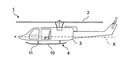
- FIG. 1 is a side view of a rotary wing aircraft equipped with a skid as a landing gear according to a first embodiment of the present invention.
- FIG. 2 is a perspective view showing the structure of a skid attached to the rotary wing aircraft shown in FIG. 1;
- FIG. 3 is a cross-sectional view showing a structural example of the cross tube shown in FIGS. 1 and 2. The figure which shows a mode that the cross tube shown in FIG. 1 thru
- FIG. 7 is a cross-sectional view showing another structural example of the cross tube shown in FIGS. 1 and 2.
- the partially expanded transverse cross-sectional view which shows the example in the case of comprising a part of two plate-shaped composite materials from which the orientation angle of fiber differs by a common fiber reinforcement layer.
- the front view which shows the structure of the skid as a landing gear concerning a 2nd embodiment of the present invention.
- a rotary wing aircraft 1 is configured by attaching a skid 4 as a landing gear to a fuselage 3 provided with a rotary wing 2.
- a typical skid 4 comprises two sled-like skid tubes 10 and two curved cross tubes 11 for attaching each skid tube 10 to the body 3 as shown in FIGS. 1 and 2 .
- Each cross tube 11 is made of a composite material in which resin is reinforced with fibers.
- the composite material include glass fiber reinforced plastic (GFRP: glass fiber reinforced plastic), resin reinforced carbon fiber reinforced plastic (CFRP: carbon fiber reinforced plastic), and paper resin. Nomex (registered trademark) which has
- FIG. 3 is a cross-sectional view showing a structural example of the cross tube 11 shown in FIGS. 1 and 2.
- the cross tube 11 can be manufactured by combining two curved plate-shaped composite pieces 20A and 20B. It can be coupled with agents and fasteners. Alternatively, the composite pieces 20A and 20B may be co-molded. When the composite material pieces 20A and 20B are integrally molded, a part of the composite material pieces 20A and 20B can be formed of a common fiber reinforced layer as described later.
- each of the composite material pieces 20A and 20B is an arc shape. Therefore, when the two composite material pieces 20A and 20B are combined, a cylindrical cross tube 11 is obtained. Since the cross tube 11 is curved in the length direction, each of the composite material pieces 20A and 20B also has a shape curved in the length direction.
- the first composite piece 20A can be formed of a plate-shaped composite material that covers a range of about 3/4 on the upper surface side of the cross tube 11.
- the second composite piece 20B can be made of a plate-like composite material that covers a range of about 1 ⁇ 4 on the lower surface side of the cross tube 11.
- the orientation angle of the fibers constituting the first composite piece 20A and the orientation angle of the fibers constituting the second composite piece 20B can be determined to be different from each other.
- the rigidity of the cross tube 11 can be made anisotropic.
- a composite material in which the longitudinal direction of the cross tube 11 is the longitudinal direction of fibers has high bending rigidity and tensile rigidity in the longitudinal direction of the cross tube 11.
- a composite material in which the circumferential direction perpendicular to the longitudinal direction of the cross tube 11 is the longitudinal direction of the fibers has low flexural rigidity and tensile rigidity in the longitudinal direction of the cross tube 11.
- the skid 4 having relatively small rigidity only at the lower side of the cross tube 11, and relatively large rigidity at other parts including the front side, the upper side and the rear side.
- Typical aircraft structural members are fabricated by combining composites where the fiber orientation angles are 0, 45 and 90 degrees. Therefore, also for the first composite material piece 20A and the second composite material piece 20B constituting the cross tube 11, composite materials in which the fiber orientation angles are 0 degree, 45 degrees and 90 degrees are combined and manufactured. be able to.
- cross section of the cross tube 11 is circular, fibers having an orientation angle of 90 degrees with the circumferential direction perpendicular to the length direction of the cross tube 11 as the length direction are on the cross section of the cross tube 11 It becomes an arc shape.
- the cross tube 11 As a whole is different in bending rigidity and rigidity in the axial direction as compared with the case where the laminated structure is uniform over the entire circumference. Becomes possible. That is, it is possible to manufacture the skid 4 in which the bending rigidity of the cross tube 11 is relatively low and the rigidity in the axial direction is relatively high.
- the tensile load acts on the skid tube 10. That is, a bending load acts on the initial stage of deformation of the cross tube 11, and then a tensile load acts.
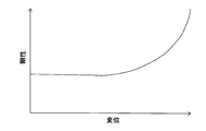
- the horizontal axis indicates the displacement of the cross tube 11
- the vertical axis indicates the stiffness of the cross tube 11.
- the rigidity on the lower side of the cross tube 11 is reduced while the rigidity in other portions is set large, as shown in FIG. 5, the rigidity changes non-linearly with changes in displacement as shown in FIG. 5.
- the cross tube 11 having the following characteristics can be manufactured. More specifically, the cross tube 11 can be provided with mechanical characteristics represented by a curve that is convex downward in a coordinate system in which the horizontal axis shown in FIG. 5 is displacement and the vertical axis is rigid.
- the fuselage 3 of the rotary wing aircraft 1 is secured to the ground while securing the amount of energy absorbed when the rotary wing aircraft 1 lands. Contact with 30 can be avoided. And the balance of the energy absorption amount at the time of landing of the rotary wing aircraft 1 and the effect of avoiding that the fuselage 3 of the rotary wing aircraft 1 contacts the ground 30 adjusts the orientation of the fibers constituting the composite material Can be optimized by
- a second composite piece 20B covering a range of 1/4 composed of a 90-degree rich composite material and a first one covering a range of 3/4 composed of a 0-degree rich composite material
- the same effect can be obtained by inverting the composite piece 20A up and down. That is, the same effect can be obtained even when manufacturing the skid 4 having relatively small rigidity only on the upper side of the cross tube 11 and relatively large rigidity in the other parts including the front side, the lower side and the rear side. it can.
- the ratio of fibers reinforced in the direction perpendicular to the longitudinal direction of the cross tube 11 out of the fibers reinforcing one of the upper and lower sides of the composite material constituting the cross tube 11 is maximized, and the rest of the composite material If the ratio of the fibers reinforcing in the longitudinal direction of the cross tube 11 among the fibers reinforcing the portion of the cross section 11 is maximized, the cross tube 11 can be given rigidity that increases nonlinearly with an increase in displacement. As a result, it is possible to obtain an effect that it is possible to prevent the fuselage 3 of the rotary wing aircraft 1 from contacting the ground 30 while securing the amount of energy absorbed when the rotary wing aircraft 1 lands.
- FIG. 6 is a cross-sectional view showing another structural example of the cross tube 11 shown in FIGS. 1 and 2.
- the cross tube 11 can also be configured with four composite pieces 20C, 20D, 20E, and 20F on the front side, the rear side, the upper side, and the lower side. That is, the cross tube 11 can also be divided into four.
- the composite pieces 20C and 20D disposed on the front side and the rear side of the cross tube 11 should be made of a 0 degree rich composite material Can.
- the composite pieces 20E and 20F disposed on the upper and lower sides of the cross tube 11 can be made of a 90 ° rich composite.
- the range formed by the 90 degree rich composite material becomes wider in the example of four division shown in FIG. 6 as compared with the structural example of two division shown in FIG.
- the proportion of certain composites may be reduced.
- a composite having a fiber orientation angle of 0 degrees and a fiber orientation angle of 90 degrees The pieces of composite material 20C and 20D disposed on the front side and the rear side of the cross tube 11 can be made of a composite material rich in 0 degree while making the ratio of materials the same.
- the proportion of the composite material in which the fiber orientation angle is 90 degrees may be changed stepwise in three or more stages, not in two stages. That is, the cross tube 11 can be divided into areas finer than the four areas on the front side, the rear side, the upper side, and the lower side to adjust the orientation of the fibers.
- the cross tube 11 can also be provided with anisotropy without using a composite material in which the fiber orientation angle is 0 degree or a composite material in which the fiber orientation angle is 90 degrees.
- a cross whose rigidity changes nonlinearly depending on displacement also by adjusting the ratio of the composite material whose fiber orientation angle is 45 degrees or the composite material whose fiber orientation angle is 60 degrees
- the tube 11 can be designed and manufactured.
- the specific fiber orientation can be determined by simulation or test so as to obtain the desired non-linear change in stiffness.
- the hollow cross tube 11 composed of a composite material can be manufactured by any method.
- a prepreg of a sheet in which fibers are impregnated with uncured thermosetting resin is laminated, and the laminate of the prepreg is shaped according to the shape of the composite material, and then an autoclave device is formed. And heat transfer curing, and RTM (Resin Transfer Molding).
- the RTM method is a method of molding a composite material in which sheet-like fibers are laminated and shaped, and then a thermosetting resin is impregnated to carry out heat curing.
- a method of impregnating fibers with a resin under vacuum pressure is called VaRTM (Vacuum assisted Resin Transfer Molding) method.
- the cross tube 11 may be manufactured by a hybrid molding method in which the lamination of prepregs and the RTM method are used in combination.
- the cross tube 11 is hollow. Therefore, for example, the cross tube 11 can be integrally molded by a method of laminating a prepreg or fiber on a water-soluble core and molding the composite material by heat curing of the resin impregnated in the fiber and then removing the core. .
- the cross tube 11 can be manufactured by laminating at least two types of prepregs or fibers having different reinforcing directions. For this reason, manufacturing labor can be reduced.
- Another manufacturing method is a method in which the curved composite pieces constituting the cross tube 11 are separately heat-formed and then assembled.
- the cross tube 11 is constituted by four composite material pieces 20C, 20D, 20E, and 20F on the front side, the rear side, the upper side, and the lower side as illustrated in FIG.
- Each of the composite pieces 20C, 20D, 20E, and 20F can be thermoformed using a mold having the same.
- the cross tube 11 can be manufactured by assembling each composite material piece 20C, 20D, 20E, 20F after thermoforming. For this reason, if the cross tube 11 is divided into four as illustrated in FIG. 6, manufacture using a mold becomes easy.
- the first composite piece 20A covering the front side, the upper side and the rear side is water-soluble
- the second composite piece 20B which is heat-formed using a flexible core, a flexible bladder bag or the like and which constitutes the lower side of the cross tube 11 is a mold having a convexly curved surface. It can be thermoformed using. Then, the first composite piece 20A and the second composite piece 20B after molding can be assembled to produce the cross tube 11. In this case, since the two composite material pieces 20A and 20B are to be assembled, the assembling operation becomes easier as compared to the case where the cross tube 11 is divided into four.
- the first composite piece 20A covering the front side, the upper side and the rear side may be further divided into two composite pieces so that the mold can be removed from the composite pieces.
- the cross tube 11 shown in FIG. 3 can be manufactured by heat curing of the three composite pieces using a mold and assembly of the composite pieces after the heat curing.
- bonding of the composite material pieces can be performed using an adhesive or a metal fitting.
- the cross tube 11 When manufacturing the cross tube 11 by assembly, the cross tube 11 can also be divided in the longitudinal direction. In this case, if the cross tube 11 is divided into a length that allows the core to be pulled out, it is possible to integrally form a composite material piece having a circular cross section.
- the fiber orientation angle Even in the case of a plurality of arc-shaped composites having different numbers, as described above, some fiber reinforced layers can be made common.
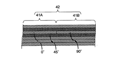
- FIG. 7 is a partially enlarged cross-sectional view showing an example in which a part of two plate-shaped composite materials having different fiber orientation angles are constituted by a common fiber reinforced layer.
- the rotary wing aircraft 1 as described above is made of a composite material and the cross tube 11 constituting the skid 4 which is a landing gear. Moreover, the skid 4 mentioned above is provided with the rigidity which changes non-linearly according to a displacement to the cross tube 11 using the anisotropy of a composite material.
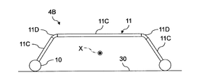
- FIG. 9 is a front view showing the configuration of a skid as a landing gear according to a third embodiment of the present invention.
- the cross tube 11 can be configured by a non-curved portion 11C and a curved portion 11D. That is, the central portion and both end portions of the cross tube 11 can be configured by the non-curved portions 11C, and the curved portions 11D can be connected between the central and non-curved portions 11C on both sides.
- the core can be easily pulled out of the non-curved portion 11C.
- the non-curved portion 11C by integral molding of the composite material in which the fiber orientation angle is not constant.
- the merits of the composite material can be effectively utilized. That is, the curved portion 11D, which is difficult to be manufactured by a composite material, can be easily manufactured by metal, and the non-curved portion 11C, which is easily manufactured by a composite material, can be manufactured by a composite material. It is possible to take advantage of the characteristics of the composite material such as weight reduction and provision of stiffness that changes non-linearly.
- the non-curved portion 11C made of a composite material and the curved portion 11D made of metal can be connected by an adhesive or a fastener.
Landscapes
- Engineering & Computer Science (AREA)
- Mechanical Engineering (AREA)
- Aviation & Aerospace Engineering (AREA)
- Laminated Bodies (AREA)
- Moulding By Coating Moulds (AREA)
- Railway Tracks (AREA)
Abstract
実施形態に係る回転翼航空機の降着装置は、回転翼航空機が着陸する際における十分なエネルギ吸収と、機体の地面への接触の回避をより良好な条件下において両立できるように、2本のスキッドチューブと、前記2本のスキッドチューブを連結して回転翼航空機の胴体に取付けるためのクロスチューブとを有し、前記クロスチューブの少なくとも一部を複合材で構成したものである。また、実施形態に係る回転翼航空機は、着陸する際における十分なエネルギ吸収と、機体の地面への接触の回避をより良好な条件下において両立できるように、上述した降着装置を備えたものである。
Description
本発明の実施形態は、回転翼航空機の降着装置、回転翼航空機及び回転翼航空機の降着方法に関する。
従来、回転翼航空機の降着装置として、スキッドが知られている(例えば特許文献1、特許文献2及び特許文献3参照)。スキッドは、そり状の滑り材を使用した降着装置である。回転翼航空機が着陸する際には、スキッドの変形によってエネルギが吸収される。
回転翼航空機が着陸する際におけるエネルギの吸収量を十分に確保するためには、スキッドに大きな変形を生じさせることが必要となる。その反面、スキッドが過剰に変形すると、機体が地面に接触する恐れがある。このため、スキッドの設計においては、十分なエネルギ吸収と、機体の地面への接触の回避を両立させることが重要である。
そこで、本発明は、回転翼航空機が着陸する際における十分なエネルギ吸収と、機体の地面への接触の回避をより良好な条件下において両立できるようにすることを目的とする。
本発明の実施形態に係る回転翼航空機の降着装置は、2本のスキッドチューブと、前記2本のスキッドチューブを連結して回転翼航空機の胴体に取付けるためのクロスチューブとを有し、前記クロスチューブの少なくとも一部を複合材で構成したものである。
また、本発明の実施形態に係る回転翼航空機は、上述した降着装置を備えたものである。
また、本発明の実施形態に係る回転翼航空機の降着方法は、回転翼航空機の降着装置を構成する2本のスキッドチューブを連結して前記回転翼航空機の胴体に取付けるためのクロスチューブの少なくとも一部を複合材で構成することによって、前記回転翼航空機の着陸時におけるエネルギの吸収量を確保しつつ前記回転翼航空機の胴体が地面に接触することを回避するようにしたものである。
本発明の実施形態に係る回転翼航空機の降着装置、回転翼航空機及び回転翼航空機の降着方法について添付図面を参照して説明する。
(第1の実施形態)
(構成及び機能)
図1は本発明の第1の実施形態に係る降着装置としてのスキッドを備えた回転翼航空機の側面図であり、図2は図1に示す回転翼航空機に取付けられるスキッドの構造を示す斜視図である。
(構成及び機能)
図1は本発明の第1の実施形態に係る降着装置としてのスキッドを備えた回転翼航空機の側面図であり、図2は図1に示す回転翼航空機に取付けられるスキッドの構造を示す斜視図である。
図1に示すように回転翼航空機1は、回転翼2を備えた胴体3に降着装置としてスキッド4を取付けて構成される。典型的なスキッド4は、図1及び図2に示すようにそり状の2本のスキッドチューブ10と、各スキッドチューブ10を胴体3に取付けるための湾曲した2本のクロスチューブ11で構成される。
各スキッドチューブ10は、回転翼航空機1の基準軸の1つである縦軸Xに平行に配置される滑り材である。一方、各クロスチューブ11は、2本のスキッドチューブ10を連結した状態で胴体3の下部に取付けるための支持部材である。従って、各クロスチューブ11の長さ方向は、回転翼航空機1の縦軸Xに概ね垂直な平面上において曲線となる。そして、一方のクロスチューブ11が前方側に配置され、他方のクロスチューブ11が後方側に配置される。更に、各クロスチューブ11は、変形することによって回転翼航空機1が着陸する際にエネルギを吸収する役割も担う。
各クロスチューブ11は、樹脂を繊維で強化した複合材で構成される。複合材の例としては、ガラス繊維で樹脂を強化したガラス繊維強化プラスチック(GFRP: Glass fiber reinforced plastics)、炭素繊維で樹脂を強化した炭素繊維強化プラスチック(CFRP: Carbon Fiber Reinforced Plastics)及び紙で樹脂を強化したノーメックス(登録商標)が挙げられる。
従来のスキッドチューブ及びクロスチューブは金属で構成されていた。複合材は金属に比べて比剛性が高い。従って、少なくとも回転翼航空機1が着陸する際においてエネルギ吸収を担うクロスチューブ11を複合材で構成することによって、軽量化を図ることができる。もちろん、スキッドチューブ10を複合材で構成してもよい。
クロスチューブ11を複合材で構成すると、クロスチューブ11の機械的特性に異方性を付与することが可能となる。すなわち、複合材は、繊維の積層方向に依存して機械的特性が変化し、かつ異方性を有する。そこで、複合材の異方性を利用して鉛直方向におけるクロスチューブ11の曲げに対する剛性を小さくする一方、クロスチューブ11の長さ方向における引張に対する剛性を大きくすることができる。つまり、曲げには弱く、引張には強いクロスチューブ11を設計及び製作することができる。
図3は図1及び図2に示すクロスチューブ11の構造例を示す横断面図である。
図3に例示されるようにクロスチューブ11を、2枚の湾曲した板状の複合材片20A、20Bを組合わせることによって製作することができる、複合材片20A、20B同士は、例えば、接着剤やファスナで結合することができる。或いは、複合材片20A、20Bを一体成形(Co-curing)しても良い。複合材片20A、20Bを一体成形する場合には、後述するように複合材片20A、20Bの一部を共通の繊維強化層で構成することもできる。
各複合材片20A、20Bの横断面の形状は、円弧状となっている。このため、2枚の複合材片20A、20Bを組合わせると円筒状のクロスチューブ11となる。クロスチューブ11は長さ方向に湾曲しているため、各複合材片20A、20Bも長さ方向に湾曲した形状となる。
第1の複合材片20Aは、クロスチューブ11の上面側における3/4程度の範囲をカバーする板状の複合材で構成することができる。他方、第2の複合材片20Bは、クロスチューブ11の下面側における1/4程度の範囲をカバーする板状の複合材で構成することができる。そして、第1の複合材片20Aを構成する繊維の配向角と、第2の複合材片20Bを構成する繊維の配向角とを、互いに異なる配向角に決定することができる。
そうすると、クロスチューブ11の剛性に異方性を付与することができる。クロスチューブ11の長さ方向が繊維の長さ方向である複合材は、クロスチューブ11の長さ方向における曲げ剛性及び引張剛性が高い。一方、クロスチューブ11の長さ方向に垂直な円周方向が繊維の長さ方向である複合材は、クロスチューブ11の長さ方向における曲げ剛性及び引張剛性が低い。
そこで、クロスチューブ11の下側における第2の複合材片20Bを強化する繊維のうち、クロスチューブ11の長さ方向に垂直な方向に強化する繊維の割合を最大に設定することができる。他方、クロスチューブ11の前方側、上側及び後方側から成る残りの部分をカバーする第1の複合材片20Aを強化する繊維のうち、クロスチューブ11の長さ方向に強化する繊維の割合を最大に設定することができる。
そうすると、クロスチューブ11の下側のみ剛性が相対的に小さく、前方側、上側及び後方側を含むその他の部分では剛性が相対的に大きいスキッド4を製作することができる。
典型的な航空機の構造部材は、繊維の配向角が0度、45度及び90度である複合材を組合わせて製作される。このため、クロスチューブ11を構成する第1の複合材片20A及び第2の複合材片20Bについても、繊維の配向角が0度、45度及び90度である複合材を組合わせて製作することができる。
尚、クロスチューブ11の横断面が円形であれば、クロスチューブ11の長さ方向に垂直な円周方向を長さ方向とする配向角が90度の繊維は、クロスチューブ11の横断面上において円弧状となる。一方、クロスチューブ11の長さ方向を、長さ方向とする配向角が0度の繊維は、クロスチューブ11の横断面上において点状となる。
クロスチューブ11には、最低限の剛性を各方向に付与することが重要である。そこで、例えば、第1の複合材片20A及び第2の複合材片20Bの双方に、繊維の配向角が0度である複合材及び繊維の配向角が90度である複合材がいずれも最低10%以上含まれるように繊維の配向を決定することができる。
実用的な例として、クロスチューブ11の前方側、上側及び後方側をカバーする第1の複合材片20Aについては、繊維の配向角が0度である複合材の割合を50%、45度である複合材の割合を40%、90度である複合材の割合を10%とする0度リッチな複合材とすることができる。他方、クロスチューブ11の下側をカバーする第2の複合材片20Bについては、繊維の配向角が0度である複合材の割合を10%、45度である複合材の割合を40%、90度である複合材の割合を50%とする90度リッチな複合材とすることができる。
クロスチューブ11の下側をカバーする第2の複合材片20Bのみを90度リッチな複合材とし、クロスチューブ11の前方側、上側及び後方側をカバーする第1の複合材片20Aを0度リッチな複合材とすると、クロスチューブ11の下側のみが曲げ変形し易く、クロスチューブ11の前方側、上側及び後方側は曲げ変形し難いクロスチューブ11となる。
クロスチューブ11の曲げ剛性に効くのは、主に上側と下側の剛性である。一方、クロスチューブ11の軸方向における剛性に効くのは、全周の剛性である。従って、上述したような複合材の積層構成にすると、クロスチューブ11全体としては、全周に亘って均一な積層構成とする場合と比べて、曲げ剛性と軸方向における剛性に差異を生じさせることが可能になる。つまり、クロスチューブ11の曲げ剛性が相対的に低く、軸方向における剛性が相対的に高いスキッド4を製作することができる。
図4は図1乃至図3に示すクロスチューブ11が変形する様子を示す図である。
回転翼航空機1が着陸すると、図4において実線で示すような湾曲形状を有する変形前におけるクロスチューブ11に上下方向の荷重が作用することになる。このため、図4において点線で示すようにクロスチューブ11には概ね鉛直下方の曲げ変形が生じる。
クロスチューブ11の曲げ変形が大きくなると、クロスチューブ11には概ね水平方向の荷重が作用することになる。その結果、スキッドチューブ10と地面30との間には、摩擦力が生じる。スキッドチューブ10と地面30との間における摩擦力が最大静止摩擦力を超えると、図4において一点鎖線で示すようにクロスチューブ11は、水平方向に広がるように変形する。
このため、スキッドチューブ10には、曲げ荷重に加えて引張荷重が作用することになる。すなわち、クロスチューブ11の変形の初期段階には曲げ荷重が作用し、その後、引張荷重が作用する。
そこで、図3に例示されるように、クロスチューブ11の下側の剛性を小さくする一方、その他の部分における剛性を大きく設定することができる。これにより、回転翼航空機1が着陸してクロスチューブ11に上下方向の曲げ荷重が作用した段階では、クロスチューブ11の下側を容易に変形させることによってエネルギを十分に吸収することができる。そして、クロスチューブ11の変形が大きくなり、クロスチューブ11に引張荷重が作用する段階では、クロスチューブ11の前方側、上側及び後方側に付与された剛性によって変形の増加を抑制することができる。その結果、回転翼航空機1の胴体3が地面30に接触することを確実に回避することができる。
図5は図1乃至図3に示すクロスチューブ11に付与される機械的特性の一例を示すグラフである。
図5において横軸はクロスチューブ11の変位を示し、縦軸はクロスチューブ11の剛性を示す。図3に例示されるように、クロスチューブ11の下側の剛性を小さくする一方、その他の部分における剛性を大きく設定すると、図5に示すように、変位の変化に対して剛性が非線形に変化する特性を有するクロスチューブ11を製作することができる。より具体的には、図5に示す横軸を変位とし、縦軸を剛性とする座標系において下に凸となる曲線で表される機械的特性をクロスチューブ11に付与することができる。
このように変形が大きくなる程、剛性が高くなる非線形な特性をクロスチューブ11に付与すれば、回転翼航空機1の着陸時におけるエネルギの吸収量を確保しつつ回転翼航空機1の胴体3が地面30に接触することを回避することができる。そして、回転翼航空機1の着陸時におけるエネルギの吸収量と、回転翼航空機1の胴体3が地面30に接触することを回避する効果のバランスは、複合材を構成する繊維の配向を調節することによって好適化することができる。
尚、90度リッチな複合材で構成される1/4の範囲をカバーする第2の複合材片20Bと、0度リッチな複合材で構成される3/4の範囲をカバーする第1の複合材片20Aを上下反転させても同様な効果が得られる。すなわち、クロスチューブ11の上側のみ剛性が相対的に小さく、前方側、下側及び後方側を含むその他の部分では剛性が相対的に大きいスキッド4を製作しても、同様な効果を得ることができる。
つまり、クロスチューブ11を構成する複合材の上側及び下側のいずれか一方を強化する繊維のうちクロスチューブ11の長さ方向に垂直な方向に強化する繊維の割合を最大とし、複合材の残りの部分を強化する繊維のうちクロスチューブ11の長さ方向に強化する繊維の割合を最大とすれば、クロスチューブ11に変位の増加に伴って非線形に増加する剛性を付与することができる。その結果、回転翼航空機1の着陸時におけるエネルギの吸収量を確保しつつ回転翼航空機1の胴体3が地面30に接触することを回避することができるという効果を得ることができる。
図6は図1及び図2に示すクロスチューブ11の別の構造例を示す横断面図である。
図6に例示されるようにクロスチューブ11を前方側、後方側、上側及び下側の4つの複合材片20C、20D、20E、20Fで構成することもできる。すなわち、クロスチューブ11を4分割することもできる。
この場合、クロスチューブ11の前方側及び後方側に配置される複合材片20C、20Dについては、図3に示す第1の複合材片20Aと同様に、0度リッチな複合材で構成することができる。他方、クロスチューブ11の上側及び下側に配置される複合材片20E、20Fについては、90度リッチな複合材で構成することができる。
但し、図3に示す2分割の構造例と比較して、図6に示す4分割の例では、90度リッチな複合材で構成される範囲が広くなるため、繊維の配向角が90度である複合材の割合を減らしてもよい。具体例として、クロスチューブ11の上側及び下側に配置される複合材片20E、20Fについては、繊維の配向角が0度である複合材の割合と、繊維の配向角が90度である複合材の割合を同じにする一方、クロスチューブ11の前方側及び後方側に配置される複合材片20C、20Dについては、0度リッチな複合材で構成することができる。
つまり、クロスチューブ11の前方側及び後方側に配置される複合材片20C、20Dに含まれる、繊維の配向角が90度である複合材の割合よりも、クロスチューブ11の上側及び下側に配置される複合材片20E、20Fに含まれる、繊維の配向角が90度である複合材の割合を大きくすれば、目的とする異方性をクロスチューブ11に付与することができる。換言すれば、クロスチューブ11を構成する複合材の上側及び下側を強化する繊維のうちクロスチューブ11の長さ方向に垂直な方向に強化する繊維の割合を、複合材の前方側及び後方側を強化する繊維のうちクロスチューブ11の長さ方向に垂直な方向に強化する繊維の割合よりも大きくすれば、クロスチューブ11に変位の増加に伴って非線形に増加する剛性を付与することができる。
上述した例の他、繊維の配向角が90度である複合材の割合を2段階ではなく、3段階以上で段階的に変えるようにしてもよい。すなわち、クロスチューブ11を前方側、後方側、上側及び下側の4つの領域よりも更に細かい領域に分割して繊維の配向を調整することもできる。また、必ずしも繊維の配向角が0度である複合材や繊維の配向角が90度である複合材を使用せずにクロスチューブ11に異方性を付与することもできる。具体例として、繊維の配向角が45度である複合材の割合や繊維の配向角が60度である複合材の割合を調節することによっても、変位に依存して非線形に剛性が変化するクロスチューブ11を設計及び製作することができる。
そして、具体的な繊維の配向については、目的とする剛性の非線形な変化が得られるようにシミュレーションや試験によって決定することができる。
複合材で構成される中空のクロスチューブ11は、任意の方法で製作することができる。複合材の代表的な成形法としては、未硬化の熱硬化性樹脂を繊維に含浸させたシートのプリプレグを積層し、プリプレグの積層体を複合材の形状に合わせて賦形した後、オートクレーブ装置で加熱硬化する方法と、RTM(Resin Transfer Molding)法が挙げられる。
RTM法は、シート状の繊維を積層して賦形した後に熱硬化性樹脂を含浸させて加熱硬化を行う複合材の成形方法である。RTM法のうち真空圧で繊維に樹脂を含浸させる手法は、VaRTM(Vacuum assisted Resin Transfer Molding)法と呼ばれる。また、プリプレグの積層と、RTM法を併用するハイブリッド成形法でクロスチューブ11を製作するようにしてもよい。
クロスチューブ11は中空である。このため、例えば水溶性の中子にプリプレグ又は繊維を積層し、繊維に含浸させた樹脂の加熱硬化によって複合材を成形した後に中子を除去する製法によってクロスチューブ11を一体成形することができる。この場合、図3に例示されるように、クロスチューブ11を2分割とすれば、強化方向が異なる少なくとも2種類のプリプレグ又は繊維の積層によってクロスチューブ11を製作することができる。このため、製造労力を低減することができる。
別の製造方法として、クロスチューブ11を構成する湾曲した複合材片を別々に加熱成形した後、組立てる方法が挙げられる。この場合、図6に例示されるようにクロスチューブ11を前方側、後方側、上側及び下側の4つの複合材片20C、20D、20E、20Fで構成すれば、凸状に湾曲した表面を有する成形型を使用して、各複合材片20C、20D、20E、20Fをそれぞれ加熱成形することができる。そして、加熱成形後における各複合材片20C、20D、20E、20Fを組立てることによってクロスチューブ11を製作することができる。このため、図6に例示されるようにクロスチューブ11を4分割とすれば、成形型を用いた製作が容易となる。
一方、図3に例示されるように、クロスチューブ11を2つの複合材片20A、20Bで構成する場合においても、前方側、上側及び後方側をカバーする第1の複合材片20Aについては水溶性の中子や可撓性を有するブラダバッグ等を使用して加熱成形し、クロスチューブ11の下側を構成する第2の複合材片20Bについては、凸状に湾曲した表面を有する成形型を使用して加熱成形することができる。そして、成形後における第1の複合材片20A及び第2の複合材片20Bを組立ててクロスチューブ11を製作することができる。この場合、組立ての対象となるのは、2つの複合材片20A、20Bであるため、クロスチューブ11を4分割とする場合に比べて組立作業が容易となる。
もちろん、前方側、上側及び後方側をカバーする第1の複合材片20Aを更に2つの複合材片に分割し、成形型を複合材片から取り外せるようにしてもよい。この場合、成形型を用いた3つの複合材片の加熱硬化と、加熱硬化後における複合材片の組立てによって、図3に示すクロスチューブ11を製作することができる。
尚、一体成形を行わずに組立てによってクロスチューブ11を製作する場合における複合材片同士の接合は、接着剤や金具を用いて行うことができる。
組立てによってクロスチューブ11を製作する場合には、クロスチューブ11を長さ方向に分割することもできる。その場合、中子を引き抜くことができる程度の長さにクロスチューブ11を分割すれば、横断面が円形の複合材片を一体成形することが可能となる。
クロスチューブ11を長さ方向に分割する場合や、水溶性の中子を使用してクロスチューブ11を成形する場合など、クロスチューブ11を円周方向に一体成形する場合には、繊維の配向角が異なる複数の円弧状の複合材であっても、上述したように、一部の繊維強化層を共通にすることができる。
図7は繊維の配向角が異なる2枚の板状の複合材の一部を共通の繊維強化層で構成する場合の例を示す部分拡大横断面図である。
図7に示すように繊維の配向角が互いに異なる2枚の板状の複合材片41A、41Bの端部を連結して1枚の板状の複合材42を製作する場合、一部の繊維強化層を共通にすることができる。すなわち、特定の層のみ、繊維の長さ方向が異なる繊維強化層で2枚の複合材片41A、41Bを構成することができる。
図7に示す例では、1層のみが一方の複合材片41Aでは繊維の長さ方向が0度であるのに対して他方の複合材片41Bでは繊維の長さ方向が90度となっている。そして、他の層では、繊維の長さ方向が0度、45度及び90度である共通の繊維強化層によって双方の複合材片41A、41Bが構成されている。
以上のような回転翼航空機1は、降着装置であるスキッド4を構成するクロスチューブ11を複合材で製作したものである。また、上述したスキッド4は、複合材の異方性を利用して、変位に応じて非線形に変化する剛性をクロスチューブ11に付与したものである。
(効果)
このため、スキッド4を取付けた回転翼航空機1によれば、従来の金属製のスキッドを取付けた回転翼航空機に比べて軽量化を図ることができる。また、変位に応じて非線形に変化する剛性をクロスチューブ11に付与することによって、回転翼航空機1の着陸時における十分なエネルギ吸収と、胴体3と地面30との間における接触の回避を一層確実に両立させることができる。
このため、スキッド4を取付けた回転翼航空機1によれば、従来の金属製のスキッドを取付けた回転翼航空機に比べて軽量化を図ることができる。また、変位に応じて非線形に変化する剛性をクロスチューブ11に付与することによって、回転翼航空機1の着陸時における十分なエネルギ吸収と、胴体3と地面30との間における接触の回避を一層確実に両立させることができる。
(第2の実施形態)
図8は本発明の第2の実施形態に係る降着装置としてのスキッドの構成を示す正面図である。
図8は本発明の第2の実施形態に係る降着装置としてのスキッドの構成を示す正面図である。
図8に示された第2の実施形態におけるスキッド4Aでは、クロスチューブ11全体を複合材で構成せずに、クロスチューブ11の一部を複合材で構成した点が第1の実施形態におけるスキッド4と相違する。第2の実施形態におけるスキッド4Aの他の構成及び作用については第1の実施形態におけるスキッド4と実質的に異ならないためスキッド4Aのみ図示し、同一の構成又は対応する構成については同符号を付して説明を省略する。
図8に例示されるように、クロスチューブ11の湾曲量が小さい中央部分11Aを複合材で構成する一方、クロスチューブ11の両端部分11Bを金属で構成するようにしてもよい。そうすると、チューブ状の複合材の湾曲量が小さくなるため、チューブ状の複合材の製作時においてブラダバッグや中子を引き抜くことが容易となる。その結果、クロスチューブ11の製作が容易となる。すなわち、クロスチューブ11を円周方向に一体成形することが容易となる。尚、複合材で構成される中央部分11Aと、金属で構成される両端部分11Bは、接着剤やファスナで連結することができる。
このように、クロスチューブ11の少なくとも一部を複合材で構成すれば、クロスチューブ11の軽量化と、非線形に変化する剛性の付与を行うことができる。そして、非線形に変化する剛性をクロスチューブ11に付与すれば、回転翼航空機1の着陸時における十分なエネルギ吸収と、胴体3と地面との間における接触の回避を一層確実に両立させることができる。
(第3の実施形態)
図9は本発明の第3の実施形態に係る降着装置としてのスキッドの構成を示す正面図である。
(第3の実施形態)
図9は本発明の第3の実施形態に係る降着装置としてのスキッドの構成を示す正面図である。
図9に示された第3の実施形態におけるスキッド4Bでは、クロスチューブ11を湾曲の無い非湾曲部分11Cと、湾曲部分11Dで構成し、非湾曲部分11Cについては複合材で構成する一方、湾曲部分11Dについては金属で構成した点が第2の実施形態におけるスキッド4Aと相違する。第3の実施形態におけるスキッド4Bの他の構成及び作用については第2の実施形態におけるスキッド4Aと実質的に異ならないためスキッド4Bのみ図示し、同一の構成又は対応する構成については同符号を付して説明を省略する。
図9に示すようにクロスチューブ11を非湾曲部分11Cと、湾曲部分11Dで構成することができる。すなわち、クロスチューブ11の中央部分及び両端部分を非湾曲部分11Cで構成し、中央と両側の非湾曲部分11Cの間を湾曲部分11Dで連結することができる。
この場合、非湾曲部分11Cについては中子を容易に引き抜くことが可能となる。このため、繊維の配向角が一定でない複合材の一体成形によって非湾曲部分11Cを容易に製作することが可能となる。その結果、複合材のメリットを有効活用することができる。すなわち、複合材で製作することが困難な湾曲部分11Dについては金属で製作することによって製作を容易としつつ、複合材で製作することが容易な非湾曲部分11Cについては、複合材で製作することによって軽量化及び非線形に変化する剛性の付与という複合材の特質を活かすことができる。
尚、複合材で構成される非湾曲部分11Cと、金属で構成される湾曲部分11Dは、接着剤やファスナで連結することができる。
(他の実施形態)
以上、特定の実施形態について記載したが、記載された実施形態は一例に過ぎず、発明の範囲を限定するものではない。ここに記載された新規な方法及び装置は、様々な他の様式で具現化することができる。また、ここに記載された方法及び装置の様式において、発明の要旨から逸脱しない範囲で、種々の省略、置換及び変更を行うことができる。添付された請求の範囲及びその均等物は、発明の範囲及び要旨に包含されているものとして、そのような種々の様式及び変形例を含んでいる。
以上、特定の実施形態について記載したが、記載された実施形態は一例に過ぎず、発明の範囲を限定するものではない。ここに記載された新規な方法及び装置は、様々な他の様式で具現化することができる。また、ここに記載された方法及び装置の様式において、発明の要旨から逸脱しない範囲で、種々の省略、置換及び変更を行うことができる。添付された請求の範囲及びその均等物は、発明の範囲及び要旨に包含されているものとして、そのような種々の様式及び変形例を含んでいる。
Claims (11)
- 2本のスキッドチューブと、
前記2本のスキッドチューブを連結して回転翼航空機の胴体に取付けるためのクロスチューブと、
を有し、
前記クロスチューブの少なくとも一部を複合材で構成した回転翼航空機の降着装置。 - 前記クロスチューブ全体を前記複合材で構成した請求項1記載の回転翼航空機の降着装置。
- 前記クロスチューブの中央部分を前記複合材で構成する一方、前記クロスチューブの両端部分を金属で構成した請求項1記載の回転翼航空機の降着装置。
- 前記クロスチューブを湾曲の無い部分と、湾曲部分で構成し、前記湾曲の無い部分については前記複合材で構成する一方、前記湾曲部分については金属で構成した請求項1又は3記載の回転翼航空機の降着装置。
- 前記クロスチューブは、変位の変化に対して剛性が非線形に変化する特性を有する請求項1乃至4のいずれか1項に記載の回転翼航空機の降着装置。
- 前記特性は、横軸を前記変位とし、縦軸を前記剛性とする座標系において下に凸となる曲線で表される特性である請求項5記載の回転翼航空機の降着装置。
- 前記クロスチューブを構成する前記複合材の上側及び下側を強化する繊維のうち前記クロスチューブの長さ方向に垂直な方向に強化する繊維の割合を、前記複合材の前方側及び後方側を強化する繊維のうち前記クロスチューブの長さ方向に垂直な方向に強化する繊維の割合よりも大きくした請求項1乃至6のいずれか1項に記載の回転翼航空機の降着装置。
- 前記クロスチューブを構成する前記複合材の上側及び下側のいずれか一方を強化する繊維のうち前記クロスチューブの長さ方向に垂直な方向に強化する繊維の割合を最大とし、前記複合材の残りの部分を強化する繊維のうち前記クロスチューブの長さ方向に強化する繊維の割合を最大とした請求項1乃至7のいずれか1項に記載の回転翼航空機の降着装置。
- 請求項1乃至8のいずれか1項に記載の降着装置を備えた回転翼航空機。
- 回転翼航空機の降着装置を構成する2本のスキッドチューブを連結して前記回転翼航空機の胴体に取付けるためのクロスチューブの少なくとも一部を複合材で構成することによって、前記回転翼航空機の着陸時におけるエネルギの吸収量を確保しつつ前記回転翼航空機の胴体が地面に接触することを回避する回転翼航空機の降着方法。
- 前記複合材を構成する繊維の配向を調節することによって前記エネルギの吸収量を確保しつつ前記胴体が地面に接触することを回避する請求項10記載の回転翼航空機の降着方法。
Priority Applications (4)
| Application Number | Priority Date | Filing Date | Title |
|---|---|---|---|
| CN201880040783.2A CN110770122B (zh) | 2017-07-31 | 2018-04-06 | 旋翼航空器的降落装置 |
| EP18841004.7A EP3663196A4 (en) | 2017-07-31 | 2018-04-06 | UNDERCARRIAGE FOR A ROTARY WINGER |
| JP2019533894A JP6839284B2 (ja) | 2017-07-31 | 2018-04-06 | 回転翼航空機の降着装置 |
| US16/746,272 US11383828B2 (en) | 2017-07-31 | 2020-01-17 | Landing gear of rotorcraft |
Applications Claiming Priority (2)
| Application Number | Priority Date | Filing Date | Title |
|---|---|---|---|
| JP2017-147866 | 2017-07-31 | ||
| JP2017147866 | 2017-07-31 |
Related Child Applications (1)
| Application Number | Title | Priority Date | Filing Date |
|---|---|---|---|
| US16/746,272 Continuation US11383828B2 (en) | 2017-07-31 | 2020-01-17 | Landing gear of rotorcraft |
Publications (1)
| Publication Number | Publication Date |
|---|---|
| WO2019026350A1 true WO2019026350A1 (ja) | 2019-02-07 |
Family
ID=65233349
Family Applications (1)
| Application Number | Title | Priority Date | Filing Date |
|---|---|---|---|
| PCT/JP2018/014698 Ceased WO2019026350A1 (ja) | 2017-07-31 | 2018-04-06 | 回転翼航空機の降着装置 |
Country Status (5)
| Country | Link |
|---|---|
| US (1) | US11383828B2 (ja) |
| EP (1) | EP3663196A4 (ja) |
| JP (1) | JP6839284B2 (ja) |
| CN (1) | CN110770122B (ja) |
| WO (1) | WO2019026350A1 (ja) |
Cited By (1)
| Publication number | Priority date | Publication date | Assignee | Title |
|---|---|---|---|---|
| CN111993980A (zh) * | 2020-07-21 | 2020-11-27 | 南昌航空大学 | 一种无人机磁悬浮起降装置 |
Families Citing this family (3)
| Publication number | Priority date | Publication date | Assignee | Title |
|---|---|---|---|---|
| CN111439376A (zh) * | 2020-03-16 | 2020-07-24 | 陕西中航气弹簧有限责任公司 | 高姿滑撬起落架 |
| US12600466B2 (en) * | 2023-09-27 | 2026-04-14 | The Boeing Company | Landing gear assemblies, rotorcraft and rotorcraft methods |
| EP4711270A1 (en) * | 2024-09-11 | 2026-03-18 | AIRBUS HELICOPTERS DEUTSCHLAND GmbH | A skid-type landing gear for a rotorcraft |
Citations (8)
| Publication number | Priority date | Publication date | Assignee | Title |
|---|---|---|---|---|
| US5224669A (en) * | 1991-05-06 | 1993-07-06 | Aerospatiale Societe Nationale Industrielle | Landing gear for an aerodyne, with arches in composite material |
| JPH1149097A (ja) * | 1997-08-05 | 1999-02-23 | Mitsubishi Heavy Ind Ltd | スキッド式降着装置 |
| US20020008175A1 (en) * | 1999-05-19 | 2002-01-24 | Bell Helicopter Textron Inc. | Stiffness de-coupled skid landing gear |
| JP2004098832A (ja) | 2002-09-09 | 2004-04-02 | Fuji Heavy Ind Ltd | 回転翼航空機の降着装置 |
| JP2005343309A (ja) | 2004-06-03 | 2005-12-15 | Fuji Heavy Ind Ltd | 回転翼航空機の降着装置 |
| JP2007106267A (ja) * | 2005-10-13 | 2007-04-26 | Yamaha Motor Co Ltd | 無人ヘリコプタ |
| JP2009073209A (ja) | 2007-09-18 | 2009-04-09 | Toyota Motor Corp | 移動体の着陸装置 |
| WO2009155553A1 (en) * | 2008-06-20 | 2009-12-23 | Bell Helicopter Textron Inc. | Fiber-reinforced, composite, structural member exhibiting non-linear strain-to-failure and method of making same |
Family Cites Families (10)
| Publication number | Priority date | Publication date | Assignee | Title |
|---|---|---|---|---|
| FR2554210B1 (fr) * | 1983-11-02 | 1986-01-24 | Aerospatiale | Poutre flexible a forte absorption d'energie, et trains d'atterrissage et bequille arriere d'aerodyne equipes d'une telle poudre |
| FR2608242B1 (fr) * | 1986-12-12 | 1989-03-31 | Aerospatiale | Amortisseur-verin, contre-fiche le comportant, et train d'atterrissage equipe d'une telle contre-fiche |
| FR2676207B1 (fr) * | 1991-05-06 | 1993-08-27 | Aerospatiale | Train d'atterrissage pour aerodynes, a traverses en materiau composite. |
| US7467763B2 (en) * | 2005-06-03 | 2008-12-23 | Kismarton Max U | Composite landing gear apparatus and methods |
| FR2895368B1 (fr) * | 2005-12-27 | 2009-07-03 | Eurocopter France | Atterrisseur de giravion a patins et giravion comportant un tel atterrisseur |
| CN101092166A (zh) * | 2007-07-20 | 2007-12-26 | 南京航空航天大学 | 直升机橇板式起落架 |
| FR2933896B1 (fr) * | 2008-07-16 | 2010-09-24 | Sas Capaero | Procede de montage d'une piece metallique dans une piece en materiau composite |
| ATE531619T1 (de) * | 2009-08-27 | 2011-11-15 | Eurocopter Deutschland | Einziehbares fahrwerk für ein drehflügler |
| CA2837626C (en) * | 2012-12-21 | 2017-06-27 | Bell Helicopter Textron Inc. | Helicopter skid landing gear |
| CN106240805B (zh) * | 2016-08-18 | 2019-07-12 | 李雪锋 | 一种无人直升机碳纤维起落架装置 |
-
2018
- 2018-04-06 EP EP18841004.7A patent/EP3663196A4/en active Pending
- 2018-04-06 JP JP2019533894A patent/JP6839284B2/ja active Active
- 2018-04-06 CN CN201880040783.2A patent/CN110770122B/zh active Active
- 2018-04-06 WO PCT/JP2018/014698 patent/WO2019026350A1/ja not_active Ceased
-
2020
- 2020-01-17 US US16/746,272 patent/US11383828B2/en active Active
Patent Citations (8)
| Publication number | Priority date | Publication date | Assignee | Title |
|---|---|---|---|---|
| US5224669A (en) * | 1991-05-06 | 1993-07-06 | Aerospatiale Societe Nationale Industrielle | Landing gear for an aerodyne, with arches in composite material |
| JPH1149097A (ja) * | 1997-08-05 | 1999-02-23 | Mitsubishi Heavy Ind Ltd | スキッド式降着装置 |
| US20020008175A1 (en) * | 1999-05-19 | 2002-01-24 | Bell Helicopter Textron Inc. | Stiffness de-coupled skid landing gear |
| JP2004098832A (ja) | 2002-09-09 | 2004-04-02 | Fuji Heavy Ind Ltd | 回転翼航空機の降着装置 |
| JP2005343309A (ja) | 2004-06-03 | 2005-12-15 | Fuji Heavy Ind Ltd | 回転翼航空機の降着装置 |
| JP2007106267A (ja) * | 2005-10-13 | 2007-04-26 | Yamaha Motor Co Ltd | 無人ヘリコプタ |
| JP2009073209A (ja) | 2007-09-18 | 2009-04-09 | Toyota Motor Corp | 移動体の着陸装置 |
| WO2009155553A1 (en) * | 2008-06-20 | 2009-12-23 | Bell Helicopter Textron Inc. | Fiber-reinforced, composite, structural member exhibiting non-linear strain-to-failure and method of making same |
Non-Patent Citations (1)
| Title |
|---|
| See also references of EP3663196A4 |
Cited By (1)
| Publication number | Priority date | Publication date | Assignee | Title |
|---|---|---|---|---|
| CN111993980A (zh) * | 2020-07-21 | 2020-11-27 | 南昌航空大学 | 一种无人机磁悬浮起降装置 |
Also Published As
| Publication number | Publication date |
|---|---|
| CN110770122A (zh) | 2020-02-07 |
| EP3663196A4 (en) | 2021-04-21 |
| EP3663196A1 (en) | 2020-06-10 |
| US11383828B2 (en) | 2022-07-12 |
| US20200148336A1 (en) | 2020-05-14 |
| JPWO2019026350A1 (ja) | 2020-07-09 |
| JP6839284B2 (ja) | 2021-03-03 |
| CN110770122B (zh) | 2023-07-28 |
Similar Documents
| Publication | Publication Date | Title |
|---|---|---|
| US11383828B2 (en) | Landing gear of rotorcraft | |
| KR101786342B1 (ko) | 멀티박스 날개 보 및 표면 | |
| JP5314024B2 (ja) | 複合材料から形成される構造フレーム及び該構造フレームを備えている航空機の胴体 | |
| EP2121264B1 (en) | Helicopter blade mandrel, method for making the mandrel and method for molding a helicopter rotor blade | |
| EP2666622B1 (en) | Skin-stiffener transition assembly, method of manufacture and application of said skin-stiffener transition assembly | |
| EP2834063B1 (en) | Hat stiffeners with canted webs and method of forming the same | |
| US20080179459A1 (en) | Pressure bulkhead made of composite material for an aircraft | |
| EP3110623A1 (en) | Composite sandwich panel having curable composite skins with asymmetrical resin distributions | |
| US8066504B2 (en) | Helicopter blade mandrel with roller assembly | |
| CN102164817B (zh) | 具有一由合成纤维材料形成的整体耐压舱壁的机身段,以及一具有像这样的机身段的机身外壳 | |
| CA3076767A1 (en) | Landing gear system with composite flex beam | |
| EP2098448A1 (en) | Composite pressure bulkhead for aircraft | |
| US10532518B2 (en) | Hybrid metallic/composite joint with enhanced performance | |
| US9833945B2 (en) | Composite material structure forming method | |
| KR102862855B1 (ko) | 보강리브가 형성된 개량형 파이프 구조 및 이의 제조방법 | |
| JPH02209234A (ja) | 繊維強化複合材料の作製方法 | |
| WO2019182727A1 (en) | Enhanced wing efficiency via differential thermal coefficient of expansion spar caps | |
| HU230887B1 (hu) | Helikopter rotorlapát | |
| JPH03120035A (ja) | 繊維強化複合材料の作製方法 |
Legal Events
| Date | Code | Title | Description |
|---|---|---|---|
| 121 | Ep: the epo has been informed by wipo that ep was designated in this application |
Ref document number: 18841004 Country of ref document: EP Kind code of ref document: A1 |
|
| ENP | Entry into the national phase |
Ref document number: 2019533894 Country of ref document: JP Kind code of ref document: A |
|
| NENP | Non-entry into the national phase |
Ref country code: DE |
|
| ENP | Entry into the national phase |
Ref document number: 2018841004 Country of ref document: EP Effective date: 20200302 |