WO2019026437A1 - 車両用照明システム及び車両 - Google Patents
車両用照明システム及び車両 Download PDFInfo
- Publication number
- WO2019026437A1 WO2019026437A1 PCT/JP2018/022768 JP2018022768W WO2019026437A1 WO 2019026437 A1 WO2019026437 A1 WO 2019026437A1 JP 2018022768 W JP2018022768 W JP 2018022768W WO 2019026437 A1 WO2019026437 A1 WO 2019026437A1
- Authority
- WO
- WIPO (PCT)
- Prior art keywords
- vehicle
- brightness
- light
- control unit
- unit
- Prior art date
- Legal status (The legal status is an assumption and is not a legal conclusion. Google has not performed a legal analysis and makes no representation as to the accuracy of the status listed.)
- Ceased
Links
Images


Classifications
-
- B—PERFORMING OPERATIONS; TRANSPORTING
- B60—VEHICLES IN GENERAL
- B60Q—ARRANGEMENT OF SIGNALLING OR LIGHTING DEVICES, THE MOUNTING OR SUPPORTING THEREOF OR CIRCUITS THEREFOR, FOR VEHICLES IN GENERAL
- B60Q1/00—Arrangement of optical signalling or lighting devices, the mounting or supporting thereof or circuits therefor
- B60Q1/02—Arrangement of optical signalling or lighting devices, the mounting or supporting thereof or circuits therefor the devices being primarily intended to illuminate the way ahead or to illuminate other areas of way or environments
- B60Q1/04—Arrangement of optical signalling or lighting devices, the mounting or supporting thereof or circuits therefor the devices being primarily intended to illuminate the way ahead or to illuminate other areas of way or environments the devices being headlights
- B60Q1/14—Arrangement of optical signalling or lighting devices, the mounting or supporting thereof or circuits therefor the devices being primarily intended to illuminate the way ahead or to illuminate other areas of way or environments the devices being headlights having dimming means
- B60Q1/1415—Dimming circuits
- B60Q1/1423—Automatic dimming circuits, i.e. switching between high beam and low beam due to change of ambient light or light level in road traffic
- B60Q1/143—Automatic dimming circuits, i.e. switching between high beam and low beam due to change of ambient light or light level in road traffic combined with another condition, e.g. using vehicle recognition from camera images or activation of wipers
-
- B—PERFORMING OPERATIONS; TRANSPORTING
- B60—VEHICLES IN GENERAL
- B60Q—ARRANGEMENT OF SIGNALLING OR LIGHTING DEVICES, THE MOUNTING OR SUPPORTING THEREOF OR CIRCUITS THEREFOR, FOR VEHICLES IN GENERAL
- B60Q1/00—Arrangement of optical signalling or lighting devices, the mounting or supporting thereof or circuits therefor
- B60Q1/02—Arrangement of optical signalling or lighting devices, the mounting or supporting thereof or circuits therefor the devices being primarily intended to illuminate the way ahead or to illuminate other areas of way or environments
- B60Q1/04—Arrangement of optical signalling or lighting devices, the mounting or supporting thereof or circuits therefor the devices being primarily intended to illuminate the way ahead or to illuminate other areas of way or environments the devices being headlights
- B60Q1/06—Arrangement of optical signalling or lighting devices, the mounting or supporting thereof or circuits therefor the devices being primarily intended to illuminate the way ahead or to illuminate other areas of way or environments the devices being headlights adjustable, e.g. remotely-controlled from inside vehicle
- B60Q1/08—Arrangement of optical signalling or lighting devices, the mounting or supporting thereof or circuits therefor the devices being primarily intended to illuminate the way ahead or to illuminate other areas of way or environments the devices being headlights adjustable, e.g. remotely-controlled from inside vehicle automatically
- B60Q1/085—Arrangement of optical signalling or lighting devices, the mounting or supporting thereof or circuits therefor the devices being primarily intended to illuminate the way ahead or to illuminate other areas of way or environments the devices being headlights adjustable, e.g. remotely-controlled from inside vehicle automatically due to special conditions, e.g. adverse weather, type of road, badly illuminated road signs or potential dangers
-
- B—PERFORMING OPERATIONS; TRANSPORTING
- B60—VEHICLES IN GENERAL
- B60Q—ARRANGEMENT OF SIGNALLING OR LIGHTING DEVICES, THE MOUNTING OR SUPPORTING THEREOF OR CIRCUITS THEREFOR, FOR VEHICLES IN GENERAL
- B60Q1/00—Arrangement of optical signalling or lighting devices, the mounting or supporting thereof or circuits therefor
- B60Q1/02—Arrangement of optical signalling or lighting devices, the mounting or supporting thereof or circuits therefor the devices being primarily intended to illuminate the way ahead or to illuminate other areas of way or environments
- B60Q1/04—Arrangement of optical signalling or lighting devices, the mounting or supporting thereof or circuits therefor the devices being primarily intended to illuminate the way ahead or to illuminate other areas of way or environments the devices being headlights
- B60Q1/14—Arrangement of optical signalling or lighting devices, the mounting or supporting thereof or circuits therefor the devices being primarily intended to illuminate the way ahead or to illuminate other areas of way or environments the devices being headlights having dimming means
- B60Q1/1415—Dimming circuits
- B60Q1/1423—Automatic dimming circuits, i.e. switching between high beam and low beam due to change of ambient light or light level in road traffic
-
- B—PERFORMING OPERATIONS; TRANSPORTING
- B60—VEHICLES IN GENERAL
- B60Q—ARRANGEMENT OF SIGNALLING OR LIGHTING DEVICES, THE MOUNTING OR SUPPORTING THEREOF OR CIRCUITS THEREFOR, FOR VEHICLES IN GENERAL
- B60Q1/00—Arrangement of optical signalling or lighting devices, the mounting or supporting thereof or circuits therefor
- B60Q1/26—Arrangement of optical signalling or lighting devices, the mounting or supporting thereof or circuits therefor the devices being primarily intended to indicate the vehicle, or parts thereof, or to give signals, to other traffic
- B60Q1/50—Arrangement of optical signalling or lighting devices, the mounting or supporting thereof or circuits therefor the devices being primarily intended to indicate the vehicle, or parts thereof, or to give signals, to other traffic for indicating other intentions or conditions, e.g. request for waiting or overtaking
- B60Q1/507—Arrangement of optical signalling or lighting devices, the mounting or supporting thereof or circuits therefor the devices being primarily intended to indicate the vehicle, or parts thereof, or to give signals, to other traffic for indicating other intentions or conditions, e.g. request for waiting or overtaking specific to autonomous vehicles
-
- B—PERFORMING OPERATIONS; TRANSPORTING
- B60—VEHICLES IN GENERAL
- B60Q—ARRANGEMENT OF SIGNALLING OR LIGHTING DEVICES, THE MOUNTING OR SUPPORTING THEREOF OR CIRCUITS THEREFOR, FOR VEHICLES IN GENERAL
- B60Q2300/00—Indexing codes for automatically adjustable headlamps or automatically dimmable headlamps
- B60Q2300/40—Indexing codes relating to other road users or special conditions
- B60Q2300/45—Special conditions, e.g. pedestrians, road signs or potential dangers
-
- Y—GENERAL TAGGING OF NEW TECHNOLOGICAL DEVELOPMENTS; GENERAL TAGGING OF CROSS-SECTIONAL TECHNOLOGIES SPANNING OVER SEVERAL SECTIONS OF THE IPC; TECHNICAL SUBJECTS COVERED BY FORMER USPC CROSS-REFERENCE ART COLLECTIONS [XRACs] AND DIGESTS
- Y02—TECHNOLOGIES OR APPLICATIONS FOR MITIGATION OR ADAPTATION AGAINST CLIMATE CHANGE
- Y02B—CLIMATE CHANGE MITIGATION TECHNOLOGIES RELATED TO BUILDINGS, e.g. HOUSING, HOUSE APPLIANCES OR RELATED END-USER APPLICATIONS
- Y02B20/00—Energy efficient lighting technologies, e.g. halogen lamps or gas discharge lamps
- Y02B20/40—Control techniques providing energy savings, e.g. smart controller or presence detection
Definitions
- the present disclosure relates to a lighting system for a vehicle.
- the present disclosure relates to a vehicle lighting system provided in a vehicle capable of traveling in an automatic driving mode.
- the present disclosure relates to a vehicle that includes a vehicle lighting system and can travel in an automatic operation mode.
- the vehicle system automatically controls the traveling of the vehicle. Specifically, in the automatic driving mode, the vehicle system performs steering control (control of the traveling direction of the vehicle), brake based on various information obtained from sensors such as a camera and a radar (for example, laser radar and millimeter wave radar). At least one of control and accelerator control (control of vehicle braking and acceleration / deceleration) is automatically performed.
- the driver controls the travel of the vehicle, as is the case with many conventional vehicles.
- traveling of the vehicle is controlled in accordance with a driver's operation (steering operation, braking operation, accelerator operation), and the vehicle system does not automatically perform steering control, brake control, and accelerator control.
- the driving mode of a vehicle is not a concept that exists only in some vehicles, but a concept that exists in all vehicles including conventional vehicles that do not have an automatic driving function, for example, vehicle control It is classified according to the method etc.
- Patent Document 1 discloses an automatic follow-up traveling system in which a following vehicle automatically follows a preceding vehicle.
- each of the leading vehicle and the following vehicle is equipped with a lighting system, and character information for preventing other vehicles from breaking in between the leading vehicle and the following vehicle is used as the lighting system of the preceding vehicle.
- character information indicating that the vehicle is following automatically is displayed on the illumination system of the following vehicle.
- the present disclosure has a first object to provide a vehicle lighting system capable of optimizing the brightness of a light distribution pattern formed by a lighting unit in view of a driving mode of the vehicle.
- a second object of the present disclosure is to provide a vehicular illumination system capable of optimizing the brightness of light illuminating an object based on information on the object existing outside the vehicle. I assume.
- a vehicle lighting system is provided to a vehicle that can travel in an automatic driving mode.
- the vehicle lighting system is A lighting unit configured to form a light distribution pattern by emitting light towards the outside of the vehicle; And a lighting control unit configured to change the brightness of the light distribution pattern according to the driving mode of the vehicle.
- the brightness of the light distribution pattern (for example, the illuminance of the illumination area illuminated by the light distribution pattern, etc.) is changed according to the operation mode of the vehicle.
- a vehicle lighting system capable of optimizing the brightness of the light distribution pattern formed by the lighting unit in consideration of the driving mode of the vehicle.
- the lighting control unit When the operation mode of the vehicle is a manual operation mode, the brightness of the light distribution pattern is set to a first brightness, The brightness of the light distribution pattern may be set to a second brightness lower than the first brightness when the driving mode of the vehicle is an advanced driving support mode or a fully automatic driving mode.
- the brightness of the light distribution pattern when the operation mode of the vehicle is the manual operation mode, the brightness of the light distribution pattern is set to the first brightness.
- the driving mode of the vehicle when the driving mode of the vehicle is the advanced driving assistance mode or the fully automatic driving mode, the brightness of the light distribution pattern is set to the second brightness lower than the first brightness.
- the driving mode of the vehicle is the automatic driving mode, the brightness of the light distribution pattern is reduced.
- the brightness of the light distribution pattern needs to be set to such a degree that the driver can sufficiently view the surrounding environment of the vehicle.
- the surrounding environment information of the vehicle acquired by the vehicle control unit (vehicle computer) by a sensor such as a radar or a camera instead of the driver.
- the sensor can acquire the surrounding environment information of the vehicle with the brightness of the light distribution pattern lower than the brightness required for the driver to sufficiently view the surrounding environment of the vehicle. For this reason, when the driving mode of the vehicle is the advanced driving support mode or the fully automatic driving mode, the brightness of the light distribution pattern can be lowered, so that the power consumption of the battery mounted on the vehicle can be suppressed. It becomes.
- the vehicle lighting system A camera configured to detect an environment surrounding the vehicle;
- a laser radar configured to detect an environment surrounding the vehicle;
- the illumination unit, the camera, and the laser radar may be disposed in a space formed by the housing and the cover.
- the lighting unit, the camera, and the laser radar are disposed in the space formed by the housing and the cover.
- part of the light emitted from the illumination unit is internally reflected by the cover, and then part of the light reflected from the inner surface is incident on the light receiving portion of the laser radar.
- the light incident on the light receiving unit of the laser radar may adversely affect the output result (3D mapping data) of the laser radar.
- the brightness of the light distribution pattern is set to the second brightness lower than the first brightness (that is, Since the brightness of the light pattern is low), it is possible to preferably prevent the light incident on the light receiving portion of the laser radar from adversely affecting the output result of the laser radar. Therefore, it is possible to reduce the power consumption of the battery and to improve the reliability of the laser radar.
- the illumination control unit may be configured to change the shape of the light distribution pattern according to the operation mode of the vehicle.
- the shape of the light distribution pattern is changed according to the driving mode of the vehicle.
- a vehicular illumination system capable of optimizing the brightness and shape of the light distribution pattern in consideration of the driving mode of the vehicle.
- the illumination control unit may be configured to control the illumination unit such that the illuminance of the illumination area illuminated by the light distribution pattern is uniform when the operation mode of the vehicle is an automatic operation mode. Good.
- the illuminance of the illumination area illuminated by the light distribution pattern becomes uniform.
- the camera can successfully capture the surrounding environment of the vehicle.
- a vehicle including the vehicle lighting system and capable of traveling in an automatic operation mode.
- a lighting system for a vehicle is provided to a vehicle capable of traveling in an automatic operation mode.
- the vehicle lighting system is A laser radar configured to obtain detection data indicating an environment surrounding the vehicle;
- a lighting unit configured to form a light distribution pattern by emitting light towards the outside of the vehicle;
- a first surrounding environment information generation unit configured to specify an attribute of an object present outside the vehicle and a distance between the object and the vehicle based on the detection data;
- An illumination control unit configured to change the brightness of light emitted from the illumination unit and illuminating the object according to the attribute of the object and the distance between the object and the vehicle And.
- the attribute of the object and the distance between the object and the vehicle are specified based on the detection data acquired by the laser radar. Furthermore, according to the attribute of the object and the distance between the object and the vehicle, the brightness of the light illuminating the object (for example, the illuminance of the illumination area of the object illuminated by the light distribution pattern or the direction toward the object Light intensity of the lighting unit at As described above, it is possible to provide a vehicular illumination system capable of optimizing the brightness of light illuminating the object based on the information on the object present outside the vehicle.
- the lighting system for vehicles A camera configured to obtain image data indicative of a surrounding environment of the vehicle;
- the image processing apparatus may further include a second surrounding environment information generation unit configured to generate surrounding environment information indicating the surrounding environment of the vehicle based on the image data.
- the brightness of the light that illuminates the target can be optimized based on the information on the target that exists outside the vehicle, so it is suitable for imaging the environment around the vehicle using a camera. It is possible to obtain a camera light distribution pattern. Therefore, occurrence of blackout or whiteout (halation) in the image data acquired by the camera is suitably suppressed, so that the accuracy of the surrounding environment information generated based on the image data can be improved. It becomes.
- the lighting control unit When the object is a sign or a delineator, the brightness of light illuminating the object is set to a first brightness, When the object is a pedestrian, the brightness of the light illuminating the object may be set to a second brightness higher than the first brightness.
- the brightness of the light illuminating the object is set to the first brightness.
- the brightness of the light illuminating the object is set to a second brightness higher than the first brightness.
- objects with high reflectivity such as signs and delineators
- objects with low reflectivity such as pedestrians
- the brightness of the light illuminating the head of the pedestrian may be lower than the brightness of the light illuminating the body other than the head of the pedestrian.
- the brightness of the light that illuminates the head of the pedestrian is lower than the brightness of the light that illuminates the body other than the head of the pedestrian. It is possible to prevent the light from being given.
- the illumination control unit is configured to control the illumination unit such that the brightness of the light illuminating the object increases as the distance between the object and the vehicle increases. May be
- the brightness of the light that illuminates the object increases. Therefore, for example, when the distance between the object and the vehicle is large, the object is displayed small in the image data acquired by the camera (that is, the occupied area of the object in the image data is small). Since the brightness of light illuminating the object is high, it is possible to prevent the object from blacking out in the image data. Thus, it is possible to improve the detection accuracy of the object based on the image data. In addition, it is possible to improve the recognition of the driver (or the occupant) with respect to an object present at a position distant from the vehicle.
- a vehicle including the vehicle lighting system and capable of traveling in an automatic operation mode.
- FIG. 1 is a schematic view showing a top view of a vehicle provided with a vehicle system. It is a block diagram showing a vehicle system. It is a flowchart for demonstrating an example of the operation
- (A) is a figure which shows an example of the light distribution pattern in case the driving mode of a vehicle is manual driving mode or driving assistance mode.
- (B) is a figure which shows an example of a light distribution pattern in case the driving mode of a vehicle is advanced driving assistance mode or fully automatic driving mode.
- FIG. 1 is a schematic view showing a top view of a vehicle provided with a vehicle system. It is a block diagram showing a vehicle system. It is a figure which shows the functional block of the control part of the left front illumination system.
- left and right direction and “front and back direction” will be referred to as appropriate for convenience of description. These directions are relative directions set for the vehicle 1 shown in FIG.
- the “front-rear direction” is a direction including the “front direction” and the “rear direction”.
- the “left-right direction” is a direction including the “left direction” and the “right direction”.
- FIG. 1 is a schematic view showing a top view of a vehicle 1 provided with a vehicle system 2.
- the vehicle 1 is a vehicle (automobile) that can travel in an automatic driving mode, and includes a vehicle system 2.
- the vehicle system 2 includes a vehicle control unit 3, a front left illumination system 4a (hereinafter simply referred to as “illumination system 4a”), a front right illumination system 4b (hereinafter simply referred to as “illumination system 4b”) and a left rear illumination.
- At least a system 4c hereeinafter, simply referred to as “illumination system 4c”
- a right rear illumination system 4d hereinafter, simply referred to as "illumination system 4d”).
- the illumination system 4 a is provided on the left front side of the vehicle 1.
- the lighting system 4a includes a housing 24a installed on the left front side of the vehicle 1 and a light transmitting cover 22a attached to the housing 24a.
- the illumination system 4 b is provided on the right front side of the vehicle 1.
- the lighting system 4b includes a housing 24b installed on the right front side of the vehicle 1, and a light transmitting cover 22b attached to the housing 24b.
- the illumination system 4 c is provided on the left rear side of the vehicle 1.
- the lighting system 4 c includes a housing 24 c installed on the left rear side of the vehicle 1 and a light transmitting cover 22 c attached to the housing 24 c.
- the illumination system 4 d is provided on the right rear side of the vehicle 1.
- the illumination system 4d includes a housing 24d installed on the right rear side of the vehicle 1 and a light transmitting cover 22d attached to the housing 24d.
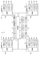
- FIG. 2 is a block diagram showing the vehicle system 2.
- the vehicle system 2 includes a vehicle control unit 3, illumination systems 4a to 4d, a sensor 5, an HMI (Human Machine Interface) 8, a GPS (Global Positioning System) 9, and a wireless communication unit. 10 and a storage device 11.
- the vehicle system 2 includes a steering actuator 12, a steering device 13, a brake actuator 14, a brake device 15, an accelerator actuator 16, and an accelerator device 17.
- the vehicle system 2 also includes a battery (not shown) configured to supply power.
- the vehicle control unit 3 is configured to control the traveling of the vehicle 1.
- the vehicle control unit 3 is configured of, for example, at least one electronic control unit (ECU: Electronic Control Unit).
- the electronic control unit may include at least one microcontroller including one or more processors and one or more memories, and other electronic circuitry including active and passive elements such as transistors.
- the processor is, for example, a central processing unit (CPU), a micro processing unit (MPU), a graphics processing unit (GPU), and / or a tensor processing unit (TPU).
- the CPU may be configured by a plurality of CPU cores.
- the GPU may be configured by a plurality of GPU cores.
- the memory includes a ROM (Read Only Memory) and a RAM (Random Access Memory).
- a vehicle control program may be stored in the ROM.
- the vehicle control program may include an artificial intelligence (AI) program for autonomous driving.
- AI is a program constructed by supervised or unsupervised machine learning using a neural network such as deep learning.
- the RAM may temporarily store a vehicle control program, vehicle control data, and / or surrounding environment information indicating a surrounding environment of the vehicle.
- the processor may be configured to expand a program specified from the vehicle control program stored in the ROM on the RAM, and execute various processes in cooperation with the RAM.
- the electronic control unit may be configured by at least one integrated circuit such as an application specific integrated circuit (ASIC) or a field-programmable gate array (FPGA). Furthermore, the electronic control unit may be configured by a combination of at least one microcontroller and at least one integrated circuit (such as an FPGA).
- ASIC application specific integrated circuit
- FPGA field-programmable gate array
- the illumination system 4a further includes a control unit 40a, an illumination unit 42a, a camera 43a, a LiDAR (Light Detection and Ranging) unit 44a (an example of a laser radar), and a millimeter wave radar 45a.
- the control unit 40a, the illumination unit 42a, the camera 43a, the LiDAR unit 44a, and the millimeter wave radar 45a, as shown in FIG. 1, are in a space Sa (a light chamber) formed by a housing 24a and a light transmission cover 22a. Will be placed.
- the control unit 40a may be disposed at a predetermined place of the vehicle 1 other than the space Sa.
- the control unit 40a may be configured integrally with the vehicle control unit 3.
- the control unit 40a is configured to control operations of the illumination unit 42a, the camera 43a, the LiDAR unit 44a, and the millimeter wave radar 45a.
- the control unit 40a functions as a lighting control unit configured to change the shape and brightness of the light distribution pattern formed by the lighting unit 42a according to the driving mode of the vehicle 1.
- the control unit 40a functions as a camera control unit configured to generate surrounding environment information indicating the surrounding environment of the vehicle 1 based on the image data after acquiring the image data acquired from the camera 43a. You may
- the control unit 40a obtains 3D mapping data (point cloud data) acquired from the LiDAR unit 44a, and then generates surrounding environment information indicating the surrounding environment of the vehicle 1 based on the 3D mapping data.
- 3D mapping data point cloud data
- control unit 40a is configured to generate surrounding environment information indicating the surrounding environment of the vehicle 1 based on the detection data after acquiring the detection data acquired from the millimeter wave radar 45a. It may function as a control unit.
- control unit 40a is configured of, for example, at least one electronic control unit (ECU).
- the electronic control unit may include at least one microcontroller including one or more processors and one or more memories, and other electronic circuits (eg, transistors, etc.).
- the processor is, for example, a CPU, an MPU, a GPU and / or a TPU.
- the CPU may be configured by a plurality of CPU cores.
- the GPU may be configured by a plurality of GPU cores.
- the memory includes a ROM and a RAM.
- the ROM may store a surrounding environment specifying program for specifying the surrounding environment of the vehicle 1.
- the peripheral environment identification program is a program constructed by supervised or unsupervised machine learning using a neural network such as deep learning.
- a peripheral environment identification program In the RAM, a peripheral environment identification program, image data acquired by the camera 43a, three-dimensional mapping data (point group data) acquired by the LiDAR unit 44a, and / or detection data acquired by the millimeter wave radar 45a, etc. are temporarily stored. May be stored.
- the processor may be configured to expand a program specified from the peripheral environment specifying program stored in the ROM on the RAM and execute various processing in cooperation with the RAM.
- the electronic control unit (ECU) may be configured by at least one integrated circuit such as an ASIC or an FPGA.
- the electronic control unit may be configured by a combination of at least one microcontroller and at least one integrated circuit (such as an FPGA).
- the illumination unit 42 a is configured to form a light distribution pattern by emitting light toward the outside (forward) of the vehicle 1.
- the illumination unit 42a has a light source for emitting light and an optical system.
- the light source may be configured by, for example, a plurality of light emitting elements arranged in a matrix (for example, N rows ⁇ M columns, N> 1, M> 1).
- the light emitting element is, for example, a light emitting diode (LED), a laser diode (LD), or an organic EL element.
- the optical system is configured to reflect light emitted from the light source toward the front of the lighting unit 42a, and to refract light reflected by the light emitted directly from the light source or reflected by the reflector. And at least one of the lenses.
- the lighting unit 42a displays a light distribution pattern for the driver (for example, a low beam light distribution pattern or a high beam light distribution pattern) in front of the vehicle 1. It is configured to form. Thus, the lighting unit 42a functions as a left headlamp unit.
- the lighting unit 42a may be configured to form a light distribution pattern for a camera in front of the vehicle 1.
- Control part 40a may be constituted so that an electric signal (for example, PWM (Pulse Width Modulation) signal) may be separately supplied to each of a plurality of light emitting elements provided in lighting unit 42a.
- the control unit 40a can individually select the light emitting elements to which the electric signal is supplied, and can adjust the duty ratio of the electric signal for each light emitting element. That is, the control unit 40a can select a light emitting element to be turned on or off among the plurality of light emitting elements arranged in a matrix, and can determine the luminance of the light emitting element that is turned on. Therefore, the control unit 40a (the illumination control unit) can change the shape and the brightness of the light distribution pattern emitted forward from the illumination unit 42a.
- PWM Pulse Width Modulation
- the camera 43a is configured to detect the surrounding environment of the vehicle 1.
- the camera 43a is configured to transmit image data to the control unit 40a after acquiring image data indicating the environment around the vehicle 1.
- the control unit 40a specifies the surrounding environment information based on the transmitted image data.
- the surrounding environment information may include, for example, information on the attribute of an object present outside the vehicle 1 and information on the position of the object relative to the vehicle 1.
- the camera 43a is configured by an imaging device such as, for example, a charge-coupled device (CCD) or a metal oxide semiconductor (CMOS).
- CCD charge-coupled device
- CMOS metal oxide semiconductor
- the camera 43a may be configured as a monocular camera or may be configured as a stereo camera.
- the control unit 40a uses parallax to make the vehicle 1 and an object existing outside the vehicle 1 (for example, based on two or more image data acquired by the stereo camera) The distance between the pedestrian and the like can be specified.
- one camera 43a is provided in the illumination system 4a in the present embodiment, two or more cameras 43a may be provided in the illumination system 4a.
- the LiDAR unit 44 a (an example of a laser radar) is configured to detect the surrounding environment of the vehicle 1.
- the LiDAR unit 44a is configured to transmit 3D mapping data to the control unit 40a after acquiring 3D mapping data (point cloud data) indicating the surrounding environment of the vehicle 1.
- the control unit 40a specifies the surrounding environment information based on the transmitted 3D mapping data.
- the surrounding environment information may include, for example, information on the attribute of an object present outside the vehicle 1 and information on the position of the object relative to the vehicle 1.
- the LiDAR unit 44a acquires information on the time of flight (TOF) ⁇ T1 of the laser beam (light pulse) at each emission angle (horizontal angle ⁇ , vertical angle ⁇ ) of the laser beam. Then, based on the information on the time of flight ⁇ T1, the information on the distance D between the LiDAR unit 44a (vehicle 1) and the object existing outside the vehicle 1 at each emission angle (horizontal angle ⁇ , vertical angle ⁇ ) is obtained can do.
- the flight time ⁇ T1 can be calculated, for example, as follows.
- Time of flight ⁇ T1 time at which laser light (light pulse) returned to LiDAR unit t1—time at which LiDAR unit emitted laser light (light pulse)
- the LiDAR unit 44a can acquire 3D mapping data indicating the environment around the vehicle 1.
- the LiDAR unit 44a includes, for example, a laser light source configured to emit a laser beam, an optical deflector configured to scan the laser beam in the horizontal direction and the vertical direction, and an optical system such as a lens. And a light receiving unit configured to receive the laser light reflected by the object.
- the central wavelength of the laser light emitted from the laser light source is not particularly limited.
- the laser light may be invisible light whose center wavelength is around 900 nm.
- the light deflector may be, for example, a MEMS (Micro Electro Mechanical Systems) mirror.
- the light receiving unit is, for example, a photodiode.
- the LIDAR unit 44a may acquire 3D mapping data without scanning the laser beam by the light deflector.
- the LiDAR unit 44a may obtain 3D mapping data in a phased array method or a flash method.
- one LiDAR unit 44a is provided in the illumination system 4a in the present embodiment, two or more LiDAR units 44a may be provided in the illumination system 4a.
- one LiDAR unit 44a is configured to detect the surrounding environment in the front area of the vehicle 1 and the other LiDAR unit 44a is a vehicle 1 It may be configured to detect the surrounding environment in the side area of the
- the millimeter wave radar 45 a is configured to detect the surrounding environment of the vehicle 1.
- the millimeter wave radar 45a is configured to transmit detection data to the control unit 40a after acquiring detection data indicating the surrounding environment of the vehicle 1.
- the control unit 40a specifies the surrounding environment information based on the transmitted detection data.
- the surrounding environment information may include, for example, information on the attribute of an object present outside the vehicle 1, information on the position of the object relative to the vehicle 1, and information on the speed of the object relative to the vehicle 1.
- the millimeter wave radar 45 a may be between the millimeter wave radar 45 a (vehicle 1) and an object existing outside the vehicle 1 by a pulse modulation method, an FM-CW (Frequency Moduled-Continuous Wave) method, or a two-frequency CW method.
- the distance D of can be obtained.
- the pulse modulation method is used, the millimeter wave radar 45a acquires the information on the time of flight ⁇ T2 of the millimeter wave at each emission angle of the millimeter wave, and then the millimeter wave radar at each emission angle based on the information on the time of flight ⁇ T2. It is possible to acquire information on the distance D between 45a (vehicle 1) and an object present outside the vehicle 1.
- the flight time ⁇ T2 can be calculated, for example, as follows.
- Time of flight ⁇ T2 time t3 when millimeter wave returns to millimeter wave radar
- the millimeter wave radar 45a is a vehicle 1 for the millimeter wave radar 45a (vehicle 1) based on the frequency f0 of the millimeter wave emitted from the millimeter wave radar 45a and the frequency f1 of the millimeter wave returned to the millimeter wave radar 45a. It is possible to obtain information on the relative velocity V of an object that exists outside of.
- the illumination system 4a may have a millimeter wave radar 45a for short distance, a millimeter wave radar 45a for medium distance, and a millimeter wave radar 45a for long distance.
- the illumination system 4b further includes a control unit 40b, an illumination unit 42b, a camera 43b, a LiDAR unit 44b, and a millimeter wave radar 45b.
- the control unit 40b, the illumination unit 42b, the camera 43b, the LiDAR unit 44b, and the millimeter wave radar 45b, as shown in FIG. 1, are in the space Sb formed by the housing 24b and the light transmission cover 22b (light chamber) Will be placed.
- the control unit 40b may be disposed at a predetermined place of the vehicle 1 other than the space Sb.
- the control unit 40 b may be configured integrally with the vehicle control unit 3.
- the control unit 40b may have the same function and configuration as the control unit 40a.
- the lighting unit 42b may have the same function and configuration as the lighting unit 42a.
- the lighting unit 42a functions as a left headlamp unit, while the lighting unit 42b functions as a right headlamp unit.
- the camera 43b may have the same function and configuration as the camera 43a.
- the LiDAR unit 44b may have the same function and configuration as the LiDAR unit 44a.
- the millimeter wave radar 45 b may have the same function and configuration as the millimeter wave radar 45 a.
- the illumination system 4c further includes a control unit 40c, an illumination unit 42c, a camera 43c, a LiDAR unit 44c, and a millimeter wave radar 45c.
- the control unit 40c, the illumination unit 42c, the camera 43c, the LiDAR unit 44c, and the millimeter wave radar 45c, as shown in FIG. 1, are in the space Sc formed by the housing 24c and the light transmission cover 22c (light chamber) Will be placed.
- the control unit 40c may be disposed at a predetermined place of the vehicle 1 other than the space Sc.
- the control unit 40c may be configured integrally with the vehicle control unit 3.
- the control unit 40c may have the same function and configuration as the control unit 40a.
- the illumination unit 42 c is configured to form a light distribution pattern by emitting light toward the outside (rear) of the vehicle 1.
- the illumination unit 42c has a light source for emitting light and an optical system.
- the light source may be configured by, for example, a plurality of light emitting elements arranged in a matrix (for example, N rows ⁇ M columns, N> 1, M> 1).
- the light emitting element is, for example, an LED, an LD or an organic EL element.
- the optical system is configured to reflect light emitted from the light source toward the front of the lighting unit 42c, and to refract light reflected by the light emitted directly from the light source or reflected by the reflector. And at least one of the lenses.
- the lighting unit 42c When the driving mode of the vehicle 1 is the manual driving mode or the driving support mode, the lighting unit 42c may be turned off. On the other hand, when the driving mode of the vehicle 1 is the advanced driving assistance mode or the fully automatic driving mode, the lighting unit 42c may be configured to form a light distribution pattern for a camera behind the vehicle 1.
- the camera 43c may have the same function and configuration as the camera 43a.
- the LiDAR unit 44c may have the same function and configuration as the LiDAR unit 44c.
- the millimeter wave radar 45c may have the same function and configuration as the millimeter wave radar 45a.
- the illumination system 4d further includes a control unit 40d, an illumination unit 42d, a camera 43d, a LiDAR unit 44d, and a millimeter wave radar 45d.
- the control unit 40d, the illumination unit 42d, the camera 43d, the LiDAR unit 44d, and the millimeter wave radar 45d are in a space Sd formed by the housing 24d and the light transmission cover 22d (light chamber) Will be placed.
- the control unit 40d may be disposed at a predetermined place of the vehicle 1 other than the space Sd.
- the control unit 40 d may be configured integrally with the vehicle control unit 3.
- the control unit 40d may have the same function and configuration as the control unit 40c.
- the lighting unit 42d may have the same function and configuration as the lighting unit 42c.
- the camera 43d may have the same function and configuration as the camera 43c.
- the LiDAR unit 44d may have the same function and configuration as the LiDAR unit 44c.
- the millimeter wave radar 45 d may have the same function and configuration as the millimeter wave radar 45 c.
- the sensor 5 may include an acceleration sensor, a speed sensor, a gyro sensor, and the like.
- the sensor 5 is configured to detect the traveling state of the vehicle 1 and to output traveling state information indicating the traveling state of the vehicle 1 to the vehicle control unit 3.
- the sensor 5 is a seating sensor that detects whether the driver is sitting in the driver's seat, a face direction sensor that detects the direction of the driver's face, an external weather sensor that detects an external weather condition, and a person in the car You may further provide a human sensor etc. which detect whether it is.
- the HMI (Human Machine Interface) 8 includes an input unit that receives an input operation from the driver, and an output unit that outputs traveling state information and the like to the driver.
- the input unit includes a steering wheel, an accelerator pedal, a brake pedal, an operation mode switching switch for switching the operation mode of the vehicle 1 and the like.
- the output unit includes a display and the like configured to display the traveling state information, the surrounding environment information, and the lighting state of the lighting system 4.
- the GPS (Global Positioning System) 9 is configured to acquire current position information of the vehicle 1 and to output the acquired current position information to the vehicle control unit 3.
- the wireless communication unit 10 receives information (for example, other vehicle traveling information and the like) related to other vehicles around the vehicle 1 from the other vehicles and also transmits information (for example, own vehicle traveling information and the like) for the vehicle 1 to the other vehicles. It is configured to transmit (inter-vehicle communication).
- the wireless communication unit 10 is configured to receive infrastructure information from an infrastructure facility such as a traffic light and a marker light and to transmit vehicle running information of the vehicle 1 to the infrastructure facility (inter-vehicle communication).
- the wireless communication unit 10 receives information on the pedestrian from a portable electronic device (smartphone, tablet, wearable device, etc.) carried by the pedestrian, and transmits the traveling information of the vehicle 1 of the vehicle 1 to the portable electronic device. It is configured to (pedal communication).
- the vehicle 1 may communicate directly with other vehicles, infrastructure equipment or portable electronic devices in an ad hoc mode, or may communicate via an access point.
- the wireless communication standard is, for example, Wi-Fi (registered trademark), Bluetooth (registered trademark), ZigBee (registered trademark) or LPWA.
- the vehicle 1 may communicate with other vehicles, infrastructure equipment, or portable electronic devices via a mobile communication network.
- the storage device 11 is an external storage device such as a hard disk drive (HDD) or a solid state drive (SSD).
- the storage device 11 may store 2D or 3D map information and / or a vehicle control program.
- the storage device 11 is configured to output map information and a vehicle control program to the vehicle control unit 3 in response to a request from the vehicle control unit 3.
- the map information and the vehicle control program may be updated via the wireless communication unit 10 and a communication network such as the Internet.
- the vehicle control unit 3 controls the steering control signal, the accelerator control signal, and the brake control signal based on the traveling state information, the surrounding environment information, the current position information and / or the map information. Automatically generate at least one of them.
- the steering actuator 12 is configured to receive a steering control signal from the vehicle control unit 3 and to control the steering device 13 based on the received steering control signal.
- the brake actuator 14 is configured to receive a brake control signal from the vehicle control unit 3 and control the brake device 15 based on the received brake control signal.
- the accelerator actuator 16 is configured to receive an accelerator control signal from the vehicle control unit 3 and to control the accelerator device 17 based on the received accelerator control signal. As described above, in the automatic driving mode, the traveling of the vehicle 1 is automatically controlled by the vehicle system 2.
- the vehicle control unit 3 when the vehicle 1 travels in the manual operation mode, the vehicle control unit 3 generates a steering control signal, an accelerator control signal and a brake control signal according to the driver's manual operation on the accelerator pedal, the brake pedal and the steering wheel. Do. As described above, in the manual operation mode, the steering control signal, the accelerator control signal, and the brake control signal are generated by the driver's manual operation, so the travel of the vehicle 1 is controlled by the driver.
- the operation mode includes an automatic operation mode and a manual operation mode.
- the automatic driving mode includes a completely automatic driving mode, an advanced driving support mode, and a driving support mode.
- the vehicle system 2 In the fully automatic operation mode, the vehicle system 2 automatically performs all travel control of steering control, brake control and accelerator control, and the driver is not in a state where the vehicle 1 can be driven.
- the vehicle system 2 In the advanced driving support mode, the vehicle system 2 automatically performs all travel control of steering control, brake control, and accelerator control, and the driver does not drive the vehicle 1 although the vehicle 1 can be driven.
- the driving support mode the vehicle system 2 automatically performs traveling control of a part of steering control, brake control and accelerator control, and the driver drives the vehicle 1 under the driving support of the vehicle system 2.
- the manual operation mode the vehicle system 2 does not automatically perform travel control, and the driver drives the vehicle 1 without driving assistance from the vehicle system 2.
- the operation mode of the vehicle 1 may be switched by operating the operation mode switch.
- the vehicle control unit 3 sets the driving mode of the vehicle 1 to four driving modes (completely automatic driving mode, advanced driving support mode, driving support mode, manual driving mode) according to the driver's operation to the drive mode switching switch. Switch between).
- the operation mode of the vehicle 1 is automatically based on the information on the travelable section where the autonomous driving vehicle can travel and the prohibited travel interval where the autonomous driving vehicle is prohibited or the information on the external weather condition. It may be switched to In this case, the vehicle control unit 3 switches the driving mode of the vehicle 1 based on these pieces of information.
- the driving mode of the vehicle 1 may be automatically switched by using a seating sensor, a face direction sensor, or the like. In this case, the vehicle control unit 3 may switch the operation mode of the vehicle 1 based on output signals from the seating sensor and the face direction sensor.
- FIG. 3 is a flowchart for explaining an example of the operation flow of the illumination system 4a.
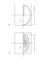
- FIG. 4A is a view showing a light distribution pattern Pm formed by the lighting unit 42a when the driving mode of the vehicle 1 is the manual driving mode or the driving support mode.
- FIG. 4B is a view showing a light distribution pattern Pa formed by the lighting unit 42a when the driving mode of the vehicle 1 is the advanced driving assistance mode or the fully automatic driving mode.
- light distribution patterns Pa and Pm shown in FIG. 4 indicate light distribution patterns projected on a virtual screen virtually installed 25 m forward of the vehicle 1.
- the plane of the virtual screen is perpendicular to the longitudinal direction of the vehicle 1.
- the contour lines of the light distribution pattern Pm shown in FIG. 4A are isolux curves.
- step S ⁇ b> 10 the control unit 40 a determines whether the operation mode of the vehicle 1 has been changed. For example, when the driving mode of the vehicle 1 is changed, the vehicle control unit 3 transmits information on the changed driving mode to the control unit 40a. Thereafter, when the control unit 40a receives the information on the changed driving mode, the control unit 40a determines that the driving mode of the vehicle 1 is changed. If the determination result in step S10 is YES, the control unit 40a determines whether the changed operation mode is the complete automatic operation mode or the advanced driving support mode (step S11). On the other hand, when the determination result of step S10 is NO, the control unit 40a stands by until the operation mode of the vehicle 1 is changed.
- the control unit 40a determines that the changed operation mode is the complete automatic operation mode or the advanced driving support mode (YES in step S11)
- the light distribution pattern emitted from the lighting unit 42a is used for automatic operation It is set to the light distribution pattern Pa of (step S12).
- FIG. 4B a light distribution pattern suitable for imaging the surrounding environment of the vehicle 1 by the camera 43a is illustrated as an example of the light distribution pattern Pa for automatic driving.
- the control unit 40a controls the illumination unit 42a so as to set the brightness of the light distribution pattern Pa to the brightness Ba (second brightness).
- the “brightness of the light distribution pattern” may be defined as the illuminance of the illumination area illuminated by the light distribution pattern (for example, the illumination area of the virtual screen illuminated by the light distribution pattern), or the light distribution pattern May be defined as the light intensity of the lighting unit 42a that forms
- the brightness Ba of the light distribution pattern Pa is the brightness necessary for the camera 43 a to sufficiently capture the surrounding environment of the vehicle 1.
- the control unit 40a may control the illumination unit 42a so that the brightness Ba of the light distribution pattern Pa is uniform. More specifically, as shown in FIG. 4B, the control unit 40a controls the illumination unit 42a so that the illuminance of the illumination area of the virtual screen illuminated by the light distribution pattern Pa becomes uniform. It is also good.
- control unit 40a performs illumination control such that the illuminance of the illumination area illuminated by the light distribution pattern Pa becomes uniform by performing light adjustment control on each of the plurality of light emitting elements of the illumination units 42a arranged in a matrix.
- the unit 42a can be controlled.
- the brightness Ba of the light distribution pattern Pa is uniform
- the uniformity of the brightness Ba of the light distribution pattern Pa is at least higher than the uniformity of the brightness Bm of the light distribution pattern Pm for the manual operation mode or the driving support mode.
- the maximum illuminance is Ba_max
- the minimum illuminance is Ba_min.
- the minimum illuminance is Bm_min while the maximum illuminance is Bm_max.
- a relational expression of (Ba_max ⁇ Ba_min) ⁇ (Bm_max ⁇ Bm_min) is established.
- the relational expression of (Ba_min / Ba_max)> (Bm_min / Bm_max) is established.
- (Ba_min / Ba_max) ⁇ 100% is preferably 95% or more and less than 100%.
- the control unit 40a determines that the changed operation mode is not the complete automatic operation mode or the advanced driving support mode (in other words, the changed operation mode is the manual operation mode or the drive support mode)
- the light distribution pattern emitted from the lighting unit 42a is set as the light distribution pattern Pm for manual operation (step S13).
- the light distribution pattern Pm may be a high beam light distribution pattern.
- the control unit 40a controls the illumination unit 42a so as to set the brightness of the light distribution pattern Pm to the brightness Bm (first brightness).
- the brightness Bm is higher than the brightness Ba.
- the brightness Bm of the light distribution pattern Pm is a brightness necessary for the driver to sufficiently view the surrounding environment of the vehicle 1.
- the control unit 40 a (lighting control unit) is configured to change the brightness of the light distribution pattern formed by the lighting unit 42 a according to the operation mode of the vehicle 1. Accordingly, it is possible to provide the illumination system 4a capable of optimizing the brightness of the illumination pattern formed by the illumination unit 42a in consideration of the operation mode of the vehicle 1.
- the driving mode of the vehicle 1 is the advanced driving support mode or the fully automatic driving mode
- the brightness of the light distribution pattern is reduced (Ba ⁇ Bm).
- the vehicle control unit 3 executes the traveling state information, the surrounding environment information, the current position information and / or the map instead of the driver. In order to control the traveling of the vehicle 1 based on information etc., the consumption of power consumption of the battery mounted on the vehicle 1 is severe.
- the camera 43a can acquire the surrounding environment information of the vehicle 1 with the brightness of the light distribution pattern lower than the brightness necessary for the driver to sufficiently view the surrounding environment of the vehicle 1. For this reason, when the driving mode of the vehicle 1 is the advanced driving support mode or the fully automatic driving mode, the brightness of the light distribution pattern can be lowered, so that the power consumption of the battery can be suppressed.
- the illumination unit 42a, the camera 43a, the LiDAR unit 44a, and the millimeter wave radar 45a are disposed in the space Sa formed by the housing 24a and the light transmitting cover 22a.
- a part of the internally reflected light may enter the light receiving portion of the LiDAR unit 44a.
- light incident on the light receiving unit of the LiDAR unit 44a may adversely affect the output result (3D mapping data) of the LiDAR unit 44a.
- the driving mode of the vehicle 1 is the advanced driving support mode or the fully automatic driving mode
- the brightness of the light distribution pattern Pa is set to the brightness Ba lower than the brightness Bm of the light distribution pattern Pm. It is possible to preferably prevent the light incident on the light receiving unit of the LiDAR unit 44a from adversely affecting the 3D mapping data. Therefore, it is possible to suppress the power consumption of the battery and to improve the reliability of the LiDAR unit 44a.
- control unit 40 a may be configured to change the shape of the light distribution pattern according to the operation mode of the vehicle 1.
- the illumination system 4a capable of optimizing the brightness and the shape of the light distribution pattern in consideration of the operation mode of the vehicle 1.
- the light distribution pattern formed by the lighting unit 42a is distributed from the light distribution pattern Pm. It is changed to pattern Pa.
- the shape of the light distribution pattern Pm projected on the virtual screen shown in FIG. 4 (a) is different from the shape of the light distribution pattern Pa projected on the virtual screen shown in FIG. 4 (b).
- both of the light distribution patterns Pm and Pa projected onto the virtual screen have cutoff lines, but the widths V in the horizontal direction are different from each other.
- the width V2 in the horizontal direction of the light distribution pattern Pa projected on the virtual screen is preferably larger than the width V1 in the horizontal direction of the light distribution pattern Pm projected on the virtual screen.
- the illumination area of the virtual screen illuminated by the light distribution pattern Pa is larger than the illumination area of the virtual screen illuminated by the light distribution pattern Pm. Since the illumination area of the light distribution pattern Pa is larger than the illumination area of the light distribution pattern Pm, it is possible to provide a light distribution pattern suitable for imaging the environment around the vehicle 1 by the camera 43a. In this respect, when the illumination area of the light distribution pattern Pa is smaller than the angle of view of the camera 43a, the camera 43a can not acquire appropriate image data at night, so the surrounding environment is accurately determined based on the image data. It may be difficult to identify.
- the shape of the light distribution pattern is changed according to the operation mode of the vehicle 1, but even if only the brightness of the light distribution pattern is changed while maintaining the shape of the light distribution pattern Good.
- the control unit 40a may control the illumination unit 42a so that the brightness of the low beam light distribution pattern becomes low.
- FIG. 5 is a schematic view showing a top view of a vehicle 1A provided with a vehicle system 2A.
- the vehicle 1A is a vehicle (automobile) that can travel in an automatic driving mode, and includes a vehicle system 2A.
- the vehicle system 2A includes a vehicle control unit 3, a front left illumination system 104a (hereinafter simply referred to as “illumination system 104a”), a front right illumination system 104b (hereinafter simply referred to as “illumination system 104b”) and a left rear illumination.
- a system 104c hereinafter simply referred to as "illumination system 104c”
- a right rear illumination system 104d hereinafter simply referred to as "illumination system 104d”).
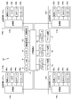
- FIG. 6 is a block diagram showing a vehicle system 2A.
- the vehicle system 2A includes a vehicle control unit 3, illumination systems 104a to 104d, a sensor 5, an HMI 8, a GPS 9, a wireless communication unit 10, and a storage device 11.
- the vehicle system 2A includes a steering actuator 12, a steering device 13, a brake actuator 14, a brake device 15, an accelerator actuator 16, and an accelerator device 17.
- the vehicle system 2A also includes a battery (not shown) configured to supply power.
- the illumination system 104a further includes a control unit 14a, an illumination unit 42a, a camera 43a, a LiDAR unit 44a, and a millimeter wave radar 45a.
- the control unit 140a, the illumination unit 42a, the camera 43a, the LiDAR unit 44a, and the millimeter wave radar 45a are, as shown in FIG. 5, in a space Sa formed by the housing 24a and the light transmission cover 22a (light chamber) Will be placed.
- the control unit 140a may be disposed at a predetermined place of the vehicle 1A other than the space Sa.
- the control unit 140a may be configured integrally with the vehicle control unit 3.
- the control unit 140a is configured by, for example, at least one electronic control unit (ECU).
- the electronic control unit may include at least one microcontroller including one or more processors and one or more memories, and other electronic circuits (eg, transistors, etc.).
- the processor is, for example, a CPU, an MPU, a GPU and / or a TPU.
- the CPU may be configured by a plurality of CPU cores.
- the GPU may be configured by a plurality of GPU cores.
- the memory includes a ROM and a RAM.
- a peripheral environment specifying program for specifying the peripheral environment of the vehicle 1A may be stored in the ROM.
- the peripheral environment identification program is a program constructed by supervised or unsupervised machine learning using a neural network such as deep learning.
- a peripheral environment identification program In the RAM, a peripheral environment identification program, image data acquired by the camera 43a, three-dimensional mapping data (point group data) acquired by the LiDAR unit 44a, and / or detection data acquired by the millimeter wave radar 45a, etc. are temporarily stored. May be stored.
- the processor may be configured to expand a program specified from the peripheral environment specifying program stored in the ROM on the RAM and execute various processing in cooperation with the RAM.
- the electronic control unit (ECU) may be configured by at least one integrated circuit such as an ASIC or an FPGA.
- the electronic control unit may be configured by a combination of at least one microcontroller and at least one integrated circuit (such as an FPGA).
- the control unit 140a may be configured to individually supply an electrical signal (for example, a PWM (Pulse Width Modulation) signal) to each of the plurality of light emitting elements provided in the lighting unit 42a.
- an electrical signal for example, a PWM (Pulse Width Modulation) signal
- the control unit 140a can individually select the light emitting elements to which the electric signal is supplied, and can adjust the duty ratio of the electric signal for each light emitting element. That is, the control unit 140a can select a light emitting element to be turned on or off among the plurality of light emitting elements arranged in a matrix, and can determine the luminance of the light emitting element that is turned on. Therefore, the control unit 140a (illumination control unit) can change the shape and brightness of the light distribution pattern emitted forward from the illumination unit 42a.
- PWM Pulse Width Modulation
- the illumination system 104b further includes a control unit 140b, an illumination unit 42b, a camera 43b, a LiDAR unit 44b, and a millimeter wave radar 45b.
- the control unit 140b, the illumination unit 42b, the camera 43b, the LiDAR unit 44b, and the millimeter wave radar 45b, as shown in FIG. 5, are in a space Sb formed by the housing 24b and the light transmission cover 22b (light chamber) Will be placed.
- the control unit 140b may be disposed at a predetermined place of the vehicle 1A other than the space Sb.
- the control unit 140 b may be configured integrally with the vehicle control unit 3.
- the control unit 140 b may have the same function and configuration as the control unit 140 a.
- the lighting unit 42b may have the same function and configuration as the lighting unit 42a.
- the lighting unit 42a functions as a left headlamp unit, while the lighting unit 42b functions as a right headlamp unit.
- the camera 43b may have the same function and configuration as the camera 43a.
- the LiDAR unit 44b may have the same function and configuration as the LiDAR unit 44a.
- the millimeter wave radar 45 b may have the same function and configuration as the millimeter wave radar 45 a.
- the illumination system 104c further includes a control unit 140c, an illumination unit 42c, a camera 43c, a LiDAR unit 44c, and a millimeter wave radar 45c.
- the control unit 140c, the illumination unit 42c, the camera 43c, the LiDAR unit 44c, and the millimeter wave radar 45c, as shown in FIG. 5, are in the space Sc formed by the housing 24c and the light transmission cover 22c (light chamber) Will be placed.
- the control unit 140c may be disposed at a predetermined place of the vehicle 1A other than the space Sc.
- the control unit 140 c may be configured integrally with the vehicle control unit 3.
- the control unit 140c may have the same function and configuration as the control unit 140a.
- the illumination system 104d further includes a control unit 140d, an illumination unit 42d, a camera 43d, a LiDAR unit 44d, and a millimeter wave radar 45d.
- the control unit 140d, the illumination unit 42d, the camera 43d, the LiDAR unit 44d, and the millimeter wave radar 45d are in a space Sd formed by the housing 24d and the light transmission cover 22d (light chamber) Will be placed.
- the control unit 140d may be disposed at a predetermined place of the vehicle 1A other than the space Sd.
- the control unit 140 d may be configured integrally with the vehicle control unit 3.
- the control unit 140d may have the same function and configuration as the control unit 140c.
- the lighting unit 42d may have the same function and configuration as the lighting unit 42c.
- the camera 43d may have the same function and configuration as the camera 43c.
- the LiDAR unit 44d may have the same function and configuration as the LiDAR unit 44c.
- the millimeter wave radar 45 d may have the same function and configuration as the millimeter wave radar 45 c.
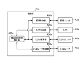
- control unit 140a is configured to control the operations of the illumination unit 42a, the camera 43a, the LiDAR unit 44a, and the millimeter wave radar 45a.
- the control unit 140a includes an illumination control unit 410a, a camera control unit 420a (an example of a second surrounding environment information generating unit), a LiDAR control unit 430a (an example of a first surrounding environment information generating unit), A wave radar control unit 440a and a surrounding environment information fusion unit 450a are provided.
- the illumination control unit 410a changes the brightness of the light emitted from the illumination unit 42a and illuminating the object (for example, a pedestrian or the like) based on the surrounding environment information of the vehicle 1A output from the LiDAR control unit 430a.
- the surrounding environment information output from the LiDAR control unit 430a includes information on the attribute of the object present outside the vehicle 1A and information on the distance D between the object and the vehicle 1A.
- the camera control unit 420a is configured to control the operation of the camera 43a and to generate surrounding environment information (hereinafter referred to as surrounding environment information I1) of the vehicle 1A based on the image data output from the camera 43a. ing.
- the LiDAR control unit 430a controls the operation of the LiDAR unit 44a and generates the surrounding environment information (hereinafter referred to as the surrounding environment information I2) of the vehicle 1A based on the 3D mapping data output from the LiDAR unit 44a.
- the millimeter wave radar control unit 440a controls the operation of the millimeter wave radar 45a, and based on the detection data output from the millimeter wave radar 45a, the surrounding environment information of the vehicle 1A (hereinafter referred to as the surrounding environment information I3).
- the surrounding environment information fusion unit 450a is configured to merge the surrounding environment information I1, I2, and I3 to generate the fused surrounding environment information If.
- the surrounding environment information If includes the detection area of the camera 43a, the detection area of the LiDAR unit 44a, and the detection area of the millimeter wave radar 45a (for example, the attribute of the object, the vehicle 1A) Position of the object, the distance between the vehicle 1A and the object and / or the speed of the object relative to the vehicle 1A).
- the surrounding environment information fusion unit 450 a transmits the surrounding environment information If to the vehicle control unit 3.
- control units 140b, 140c, and 140d may have the same function as the control unit 140a. That is, each of the control units 140b to 140d may have an illumination control unit, a camera control unit, a LiDAR control unit, a millimeter wave control unit, and a surrounding environment information fusion unit. Furthermore, the surrounding environment information fusion unit of each of the control units 140b to 140c may transmit the merged surrounding environment information If to the vehicle control unit 3. Vehicle control unit 3 controls the traveling of vehicle 1A based on surrounding environment information If and other information (travel control information, current position information, map information, etc.) transmitted from control units 140a to 140d. Good.
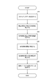
- FIG. 8 is a flowchart for explaining an example of the operation flow of the illumination system 104a according to the present embodiment.
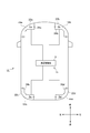
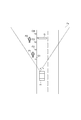
- FIG. 9 is a view showing a state of the vehicle 1A emitting the light distribution pattern Pe from the illumination unit 42a of the illumination system 104a toward an object present in front of the vehicle 1A.
- FIG. 10 is a view showing an example of a light distribution pattern Pe projected on a virtual screen virtually installed 25 m forward of the vehicle 1A.
- the virtual screen is perpendicular to the longitudinal direction of the vehicle 1A.
- the front environment of the vehicle 1A shown in FIG. 9 is shown through the virtual screen.
- the operation flow of the illumination system 104a is also applicable to the illumination system 104b.
- the vehicle 1A is traveling in the automatic driving mode (in particular, the advanced driving support mode or the fully automatic driving mode).
- the light distribution pattern Pe emitted from the lighting unit 42a is a light distribution pattern for automatic driving suitable for imaging the environment around the vehicle 1A by the camera 43a.
- the LiDAR unit 44a acquires 3D mapping data indicating the environment around the vehicle 1A (step S20).
- the LiDAR control unit 430a (an example of the first surrounding environment information generation unit) shown in FIG. 7 is present outside the vehicle 1A (particularly, in the front area) based on the 3D mapping data acquired from the LiDAR unit 44a.
- the target object to be detected is detected (step S21).
- objects present in the front area of the vehicle 1A are pedestrians P1 and P2, a guidance sign G (an example of a sign), and delineators C1 to C4. .
- the LiDAR control unit 430a only detects the presence of the object, and does not specify the attribute of the object.
- the LiDAR control unit 430a specifies the distance D between each object (pedestrian P1 or the like) and the vehicle 1A (step S22).
- the distance D between the object and the vehicle 1A may be a length of a line connecting the coordinates of the object and the coordinates of the vehicle 1A (in particular, the coordinates of the LiDAR unit 44a), or the vehicle 1A The distance between the object and the vehicle in the front-rear direction of
- the LiDAR control unit 430a specifies the attribute of each object (step S23).
- specifying the attribute of the object means specifying what the object is.
- the LiDAR control unit 430a analyzes the feature points of the objects based on the surrounding environment specifying program to specify what each object is.
- the illumination control unit 410a determines the brightness B of the light illuminating each object according to the attribute of each object and the distance D between each object and the vehicle 1A.
- the light that illuminates each object is light that is emitted from the illumination unit 42a and that forms the light distribution pattern Pe.
- “brightness B of the light illuminating the object” may be defined as the illuminance of the illumination area of the object illuminated by the light distribution pattern Pe, or as the luminous intensity of the illumination unit 42a in the direction toward the object It may be done.
- “brightness B of light illuminating an object” may be defined as the amount or concentration (light flux) of light irradiated to the object.
- the illumination control unit 410a is an object having a low reflectance (the first brightness) of light that illuminates an object having a high reflectance (the guidance sign G or the delineators C1 to C4) (a pedestrian
- the brightness B of the light illuminating each object is determined to be lower than the brightness (second brightness) of the light illuminating P1, P2).
- the illumination control unit 410a causes the brightness of the light that illuminates each object to increase the brightness B of the light that illuminates the object. Determine B.
- the reference distance D 0 only brightness B p0 brightness B of the light illuminating the pedestrian P 0 that is present in a position at a distance from the vehicle 1A.
- the brightness B c0 of the light illuminating the delineator C 0 is smaller than the brightness B p0 of the light illuminating the pedestrian P 0 , so the brightness B p0 of the light is multiplied by the coefficient ⁇ 1 ( ⁇ 1) By doing this, the brightness B c0 of the light illuminating the delineator C 0 is determined.
- the brightness of the light case the brightness B p0 of light that illuminates the pedestrian P 0 is illuminating delineators C 0 is present pedestrian P 0 and delineator C 0 at a position away from the vehicle 1A by a distance D 0 It becomes higher than B c0 .
- the brightness B c1 of the light illuminating the delineator C 1 is determined based on the coefficient ⁇ 1 associated with the distance D and the coefficient ⁇ 1 associated with the attribute of the object. Note that, in this example, when the attribute of the object is a pedestrian, the coefficient ⁇ associated with the attribute of the object is 1.
- Information on the coefficients ⁇ 1 and ⁇ 2 associated with the attribute of the object may be stored in the memory of the control unit 140 a.
- the brightness of the light which illuminates the pedestrian's P head is lower than the brightness of the light which illuminates bodies other than the pedestrian's P head. In this case, it is possible to preferably prevent the pedestrian P from being provided with glare light.
- the illumination control unit 410a directs the light distribution toward the front according to the determination of the brightness of the light illuminating each object.
- the illumination unit 42a is controlled to emit the pattern Pe.
- the illumination control unit 410a determines the brightness of the light illuminating each object.
- the illumination control unit 410a adjusts the brightness of the light illuminating each object by adjusting the brightness of each of the plurality of light emitting elements of the lighting units 42a arranged in a matrix by PWM control or the like. It becomes possible.
- FIG. 10 shows an example of the light distribution pattern Pe projected on the virtual screen.
- the brightness B p2 of light illuminating the pedestrian P2 is higher than the brightness B p1 of light illuminating the pedestrian P1.
- the brightness of light illuminating the delineators C1 to C4 is B c1 , B c2 , B c3 and B c4 respectively, the relationship of B c1 ⁇ B c2 ⁇ B c3 ⁇ B c4 holds.
- the brightness B p1 of the light that illuminates the pedestrian P1 may be higher than the brightness B c4 of the light that illuminates the delineator C4.
- the attribute of the object (for example, a pedestrian or the like) and the distance D between the object and the vehicle 1A are specified based on the 3D mapping data acquired by the LiDAR unit 44a.
- the brightness B of the light illuminating the object for example, the illuminance or the object of the illumination area of the object illuminated by the light distribution pattern Pe The light intensity etc. of the lighting unit 42a in the direction towards the object is changed.
- the illumination system 104a capable of optimizing the brightness B of the light illuminating the object based on the information on the object present outside the vehicle 1A.
- the illumination system 104b also has the same function as the illumination system 104a, the brightness B of the light illuminating the object is optimized based on the information on the object existing outside the vehicle 1A.
- the brightness of the light illuminating the object can be optimized based on the information on the object existing outside the vehicle 1A, so the periphery of the vehicle 1A using the camera 43a It is possible to obtain a camera light distribution pattern suitable for imaging of the environment.
- the dynamic range of the camera 43a is not wide, if the brightness B of the light illuminating the object with high reflectance is high, the object is likely to white out in the image data.
- the brightness B of light illuminating an object having a low reflectance is low, the object is likely to be blacked out in image data.
- an object having a high reflectance (such as a guide sign or a delineator) is illuminated by light having a low brightness, while an object having a low reflectance (such as a pedestrian) has a light having a high brightness.
- an object having a low reflectance such as a pedestrian
- glare light is given to the driver by the reflected light reflected by the object (such as a sign) having a high reflectance. Can be prevented.
- the brightness of light illuminating the object increases. Therefore, for example, when the distance D between the object and the vehicle 1A is large, the object is displayed small in the image data acquired by the camera 43a (that is, the occupied area of the object in the image data is On the other hand, since the brightness of the light illuminating the object is high, it is possible to prevent the object from blacking out in the image data. As described above, it is possible to improve the detection accuracy of the object based on the image data, and to improve the recognition of the driver or the occupant with respect to the object present at a position distant from the vehicle 1A.
- a light distribution pattern for automatic driving suitable for imaging of a camera is mentioned as an example of the light distribution pattern Pe, but the light distribution pattern Pe is a light distribution pattern for low beam, a light distribution pattern for high beam, etc. It may be a light distribution pattern for manual operation.
- the light distribution pattern Pe is a light distribution pattern for low beam, a light distribution pattern for high beam, etc. It may be a light distribution pattern for manual operation.
- the brightness of the light illuminating each of the objects present in the front area of the vehicle 1A according to the attribute of the object and the distance D between the object and the vehicle 1A. Is changed. Therefore, the visibility of the driver to the object having the low reflectance can be improved, and glare light can be prevented from being given to the driver by the light reflected by the object having the high reflectance. Therefore, it is possible to provide a lighting system capable of ensuring high driving safety in manual driving.
- a pedestrian is taken as an example of an object having a low reflectance
- a delineator and a guidance sign are given as an example of an object having a high reflectance, but an object having a low reflectance and the reflectance are High objects are not limited to these.
- the guidance label G was mentioned as an example of a label
- the driving mode of the vehicle has been described as including the fully automatic driving mode, the advanced driving support mode, the driving support mode, and the manual driving mode, but the driving mode of the vehicle is any of these four modes It should not be limited to The classification of the operation mode of the vehicle may be appropriately changed in accordance with the laws or regulations relating to automatic driving in each country. Similarly, the definitions of “completely automatic driving mode”, “advanced driving support mode”, and “driving support mode” described in the description of the present embodiment are merely examples, and the laws or regulations concerning automatic driving in each country or These definitions may be changed as appropriate in accordance with the rules.
Landscapes
- Engineering & Computer Science (AREA)
- Mechanical Engineering (AREA)
- Automation & Control Theory (AREA)
- Transportation (AREA)
- Lighting Device Outwards From Vehicle And Optical Signal (AREA)
- Traffic Control Systems (AREA)
- Non-Portable Lighting Devices Or Systems Thereof (AREA)
Abstract
車両用照明システムは、自動運転モードで走行可能な車両に設けられており、前記車両の外部に向けて光を出射することによって、配光パターンを形成するように構成された照明ユニットと、前記車両の運転モードに応じて、前記配光パターンの明るさを変更するように構成された照明制御部と、を備える。
Description
本開示は、車両用照明システムに関する。特に、本開示は、自動運転モードで走行可能な車両に設けられた車両用照明システムに関する。また、本開示は、車両用照明システムを備えると共に、自動運転モードで走行可能な車両に関する。
現在、自動車の自動運転技術の研究が各国で盛んに行われており、自動運転モードで車両(以下、「車両」は自動車のことを指す。)が公道を走行することができるための法整備が各国で検討されている。ここで、自動運転モードでは、車両システムが車両の走行を自動的に制御する。具体的には、自動運転モードでは、車両システムは、カメラ、レーダ(例えば、レーザレーダやミリ波レーダ)等のセンサから得られる各種情報に基づいてステアリング制御(車両の進行方向の制御)、ブレーキ制御及びアクセル制御(車両の制動、加減速の制御)のうちの少なくとも1つを自動的に行う。一方、以下に述べる手動運転モードでは、従来型の車両の多くがそうであるように、運転者が車両の走行を制御する。具体的には、手動運転モードでは、運転者の操作(ステアリング操作、ブレーキ操作、アクセル操作)に従って車両の走行が制御され、車両システムはステアリング制御、ブレーキ制御及びアクセル制御を自動的に行わない。尚、車両の運転モードとは、一部の車両のみに存在する概念ではなく、自動運転機能を有さない従来型の車両も含めた全ての車両において存在する概念であって、例えば、車両制御方法等に応じて分類される。
このように、将来において、公道上では自動運転モードで走行中の車両(以下、適宜、「自動運転車」という。)と手動運転モードで走行中の車両(以下、適宜、「手動運転車」という。)が混在することが予想される。また、車両に搭載された各種センサから取得される周辺環境情報の精度を飛躍的に向上させることが自動運転技術の発展におけるキーポイントとなる。
特許文献1には、先行車に後続車が自動追従走行した自動追従走行システムが開示されている。当該自動追従走行システムでは、先行車と後続車の各々が照明システムを備えており、先行車と後続車との間に他車が割り込むことを防止するための文字情報が先行車の照明システムに表示されると共に、自動追従走行である旨を示す文字情報が後続車の照明システムに表示される。
ところで、特許文献1では、車両の運転モードに応じて車両に設けられた照明ユニットから出射された光の明るさを変更することについては何ら検討されていない。
また、特許文献1では、レーザーレーダ(LiDAR等)を用いて車両の外部に存在する対象物(歩行者等)に関する情報を取得した上で、当該情報に応じて車両に設けられた照明ユニットから出射される光の明るさを変更することについては検討されていない。
本開示は、車両の運転モードを鑑みて、照明ユニットによって形成された配光パターンの明るさを最適化することが可能な車両用照明システムを提供することを第1の目的とする。
また、本開示は、車両の外部に存在する対象物に関する情報に基づいて、当該対象物を照らす光の明るさを最適化することが可能な車両用照明システムを提供することを第2の目的とする。
本開示の一態様に係る車両用照明システムは、自動運転モードで走行可能な車両に設けられる。
前記車両用照明システムは、
前記車両の外部に向けて光を出射することによって、配光パターンを形成するように構成された照明ユニットと、
前記車両の運転モードに応じて、前記配光パターンの明るさを変更するように構成された照明制御部と、を備える。
前記車両用照明システムは、
前記車両の外部に向けて光を出射することによって、配光パターンを形成するように構成された照明ユニットと、
前記車両の運転モードに応じて、前記配光パターンの明るさを変更するように構成された照明制御部と、を備える。
上記構成によれば、車両の運転モードに応じて配光パターンの明るさ(例えば、配光パターンによって照らされた照明領域の照度等)が変更される。このように、車両の運転モードを鑑みて照明ユニットによって形成された配光パターンの明るさを最適化することが可能な車両用照明システムを提供することができる。
また、前記照明制御部は、
前記車両の運転モードが手動運転モードである場合に、前記配光パターンの明るさを第1の明るさに設定し、
前記車両の運転モードが高度運転支援モード又は完全自動運転モードである場合に、前記配光パターンの明るさを前記第1の明るさよりも低い第2の明るさに設定してもよい。
前記車両の運転モードが手動運転モードである場合に、前記配光パターンの明るさを第1の明るさに設定し、
前記車両の運転モードが高度運転支援モード又は完全自動運転モードである場合に、前記配光パターンの明るさを前記第1の明るさよりも低い第2の明るさに設定してもよい。
上記構成によれば、車両の運転モードが手動運転モードである場合に、配光パターンの明るさが第1の明るさに設定される。一方、車両の運転モードが高度運転支援モード又は完全自動運転モードである場合に、配光パターンの明るさが第1の明るさよりも低い第2明るさに設定される。このように、車両の運転モードが自動運転モードである場合に、配光パターンの明るさが低下する。例えば、車両が手動運転モードで走行中の場合、配光パターンの明るさは、運転者が車両の周辺環境を十分に視認できる程度の明るさに設定される必要がある。一方、車両が高度運転支援モード又は完全自動運転モードで走行中である場合では、運転者に代わって、車両制御部(車載コンピュータ)がレーダやカメラ等のセンサによって取得された車両の周辺環境情報に基づいて車両の走行を制御するため、車両に搭載されたバッテリーの消費電力の消耗が激しい。さらに、センサは、運転者が車両の周辺環境を十分に視認できるために必要な明るさよりも低い配光パターンの明るさで車両の周辺環境情報を取得することができる。このため、車両の運転モードが高度運転支援モード又は完全自動運転モードの場合には、配光パターンの明るさを下げることができるため、車両に搭載されたバッテリーの消費電力を抑制することが可能となる。
また、前記車両用照明システムは、
前記車両の周辺環境を検出するように構成されたカメラと、
前記車両の周辺環境を検出するように構成されたレーザーレーダと、
ハウジングと、
前記ハウジングに取り付けられたカバーと、
をさらに備えてもよい。
前記照明ユニットと、前記カメラと、前記レーザーレーダとは、前記ハウジングと前記カバーによって形成された空間内に配置されてもよい。
前記車両の周辺環境を検出するように構成されたカメラと、
前記車両の周辺環境を検出するように構成されたレーザーレーダと、
ハウジングと、
前記ハウジングに取り付けられたカバーと、
をさらに備えてもよい。
前記照明ユニットと、前記カメラと、前記レーザーレーダとは、前記ハウジングと前記カバーによって形成された空間内に配置されてもよい。
上記構成によれば、照明ユニットと、カメラと、レーザーレーダがハウジングとカバーによって形成された空間内に配置される。このような配置構造では、照明ユニットから出射された光の一部がカバーによって内面反射された後に、当該内面反射された光の一部がレーザーレーダの受光部に入射することが想定される。この場合、レーザーレーダの受光部に入射した光がレーザーレーダの出力結果(3Dマッピングデータ)に悪影響を及ぼす虞がある。一方、車両の運転モードが高度運転支援モード又は完全自動運転モードである場合に、配光パターンの明るさが第1の明るさよりも低い第2の明るさに設定されているので(つまり、配光パターンの明るさが低いので)、レーザーレーダの受光部に入射した光がレーザーレーダの出力結果に悪影響を及ぼすことを好適に防止することが可能となる。従って、バッテリーの消費電力を抑えると共に、レーザーレーダの信頼性を向上させることが可能となる。
また、前記照明制御部は、前記車両の運転モードに応じて、前記配光パターンの形状を変更するように構成されてもよい。
上記構成によれば、車両の運転モードに応じて配光パターンの形状が変更される。このように、車両の運転モードを鑑みて配光パターンの明るさと形状を最適化することが可能な車両用照明システムを提供することができる。
前記照明制御部は、前記車両の運転モードが自動運転モードである場合に、前記配光パターンによって照らされた照明領域の照度が均一となるように前記照明ユニットを制御するように構成されてもよい。
上記構成によれば、車両の運転モードが自動運転モードである場合に、配光パターンによって照らされた照明領域の照度が均一となる。このように、配光パターンによって照らされた照明領域の照度が均一となるので、カメラによって車両の周辺環境を首尾よく撮像することが可能となる。
前記車両用照明システムを備え、自動運転モードで走行可能な車両が提供される。
車両の運転モードを鑑みて照明ユニットによって形成された配光パターンの明るさを最適化することが可能な車両を提供することができる。
本開示の別の一態様に係る車両用照明システムは、自動運転モードで走行可能な車両に設けられる。
前記車両用照明システムは、
前記車両の周辺環境を示す検出データを取得するように構成されたレーザーレーダと、
前記車両の外部に向けて光を出射することによって、配光パターンを形成するように構成された照明ユニットと、
前記検出データに基づいて、前記車両の外部に存在する対象物の属性および前記対象物と前記車両との間の距離を特定するように構成された第1周辺環境情報生成部と、
前記対象物の属性および前記対象物と前記車両との間の距離に応じて、前記照明ユニットから出射されると共に前記対象物を照らす光の明るさを変更するように構成された照明制御部と、を備える。
前記車両用照明システムは、
前記車両の周辺環境を示す検出データを取得するように構成されたレーザーレーダと、
前記車両の外部に向けて光を出射することによって、配光パターンを形成するように構成された照明ユニットと、
前記検出データに基づいて、前記車両の外部に存在する対象物の属性および前記対象物と前記車両との間の距離を特定するように構成された第1周辺環境情報生成部と、
前記対象物の属性および前記対象物と前記車両との間の距離に応じて、前記照明ユニットから出射されると共に前記対象物を照らす光の明るさを変更するように構成された照明制御部と、を備える。
上記構成によれば、レーザーレーダによって取得された検出データに基づいて、対象物の属性と対象物と車両との間の距離が特定される。さらに、対象物の属性と対象物と車両との間の距離に応じて、対象物を照らす光の明るさ(例えば、配光パターンによって照らされる対象物の照明領域の照度や対象物に向かう方向における照明ユニットの光度)が変更される。このように、車両の外部に存在する対象物に関する情報に基づいて、当該対象物を照らす光の明るさを最適化することが可能な車両用照明システムを提供することができる。
また、車両用照明システムは、
前記車両の周辺環境を示す画像データを取得するように構成されたカメラと、
前記画像データに基づいて、前記車両の周辺環境を示す周辺環境情報を生成するように構成された第2周辺環境情報生成部と、をさらに備えてもよい。
前記車両の周辺環境を示す画像データを取得するように構成されたカメラと、
前記画像データに基づいて、前記車両の周辺環境を示す周辺環境情報を生成するように構成された第2周辺環境情報生成部と、をさらに備えてもよい。
上記構成によれば、車両の外部に存在する対象物に関する情報に基づいて、当該対象物を照らす光の明るさを最適化することができるので、カメラを用いた車両の周辺環境の撮像に適したカメラ用配光パターンを得ることができる。このため、カメラにより取得された画像データにブラックアウト又はホワイトアウト(ハレーション)が生じることが好適に抑制されるので、当該画像データに基づいて生成される周辺環境情報の精度を向上させることが可能となる。
また、前記照明制御部は、
前記対象物が標識またはデリニエータである場合に、前記対象物を照らす光の明るさを第1の明るさに設定し、
前記対象物が歩行者の場合に、前記対象物を照らす光の明るさを前記第1の明るさよりも高い第2の明るさに設定してもよい。
前記対象物が標識またはデリニエータである場合に、前記対象物を照らす光の明るさを第1の明るさに設定し、
前記対象物が歩行者の場合に、前記対象物を照らす光の明るさを前記第1の明るさよりも高い第2の明るさに設定してもよい。
上記構成によれば、対象物が標識またはデリニエータである場合に、対象物を照らす光の明るさが第1の明るさに設定される。一方、対象物が歩行者である場合に、対象物を照らす光の明るさが第1の明るさよりも高い第2の明るさに設定される。このように、高い反射率を有する対象物(標識やデリニエータ等)は、低い明るさの光によって照らされる一方、低い反射率を有する対象物(歩行者等)は、高い明るさの光によって照らされる。このため、例えば、カメラにより取得された画像データにブラックアウト又はホワイトアウトが生じることを好適に抑制することが可能となり、画像データに基づく対象物の検出精度を飛躍的に向上させることが可能となる。さらに、低い反射率を有する対象物に対する運転者(又は乗員)の視認性を向上させると共に、高い反射率を有する対象物に反射された反射光によって運転者にグレア光が与えられることを防止することができる。
また、前記対象物が歩行者の場合に、前記歩行者の頭部を照らす光の明るさは、前記歩行者の頭部以外の身体を照らす光の明るさよりも低くてもよい。
上記構成によれば、対象物が歩行者の場合に、歩行者の頭部を照らす光の明るさは、歩行者の頭部以外の身体を照らす光の明るさよりも低いので、歩行者にグレア光が与えられることを防止することができる。
また、前記照明制御部は、前記対象物と前記車両との間の距離が大きくなるに連れて前記対象物を照らす光の明るさが高くなるように、前記照明ユニットを制御するように構成されてもよい。
上記構成によれば、対象物と車両との間の距離が大きくなるに連れて、対象物を照らす光の明るさが高くなる。このため、例えば、対象物と車両との間の距離が大きい場合には、カメラにより取得された画像データにおいて対象物は小さく表示される(つまり、画像データにおける対象物の占有面積は小さい)一方、対象物を照らす光の明るさが高いため当該画像データにおいて対象物がブラックアウトすることを防止することができる。このように、画像データに基づく対象物の検出精度を向上させることが可能となる。また、車両から離れた位置に存在する対象物に対する運転者(又は乗員)の認知度を向上させることができる。
前記車両用照明システムを備え、自動運転モードで走行可能な車両が提供される。
車両の外部に存在する対象物に関する情報に基づいて、当該対象物を照らす光の明るさを最適化することが可能な車両を提供することができる。
(第1実施形態)
以下、本開示の第1実施形態について図面を参照しながら説明する。また、本図面に示された各部材の寸法は、説明の便宜上、実際の各部材の寸法とは異なる場合がある。
以下、本開示の第1実施形態について図面を参照しながら説明する。また、本図面に示された各部材の寸法は、説明の便宜上、実際の各部材の寸法とは異なる場合がある。
また、本実施形態の説明では、説明の便宜上、「左右方向」、「前後方向」について適宜言及する。これらの方向は、図1に示す車両1について設定された相対的な方向である。ここで、「前後方向」は、「前方向」及び「後方向」を含む方向である。「左右方向」は、「左方向」及び「右方向」を含む方向である。
最初に、図1を参照して本実施形態に係る車両1について説明する。図1は、車両システム2を備える車両1の上面図を示す模式図である。図1に示すように、車両1は、自動運転モードで走行可能な車両(自動車)であって、車両システム2を備える。車両システム2は、車両制御部3と、左前照明システム4a(以下、単に「照明システム4a」という。)と、右前照明システム4b(以下、単に「照明システム4b」という。)と、左後照明システム4c(以下、単に「照明システム4c」という。)と、右後照明システム4d(以下、単に「照明システム4d」という。)を少なくとも備える。
照明システム4aは、車両1の左前側に設けられる。特に、照明システム4aは、車両1の左前側に設置されたハウジング24aと、ハウジング24aに取り付けられた透光カバー22aとを備える。照明システム4bは、車両1の右前側に設けられる。特に、照明システム4bは、車両1の右前側に設置されたハウジング24bと、ハウジング24bに取り付けられた透光カバー22bとを備える。照明システム4cは、車両1の左後側に設けられる。特に、照明システム4cは、車両1の左後側に設置されたハウジング24cと、ハウジング24cに取り付けられた透光カバー22cとを備える。照明システム4dは、車両1の右後側に設けられる。特に、照明システム4dは、車両1の右後側に設置されたハウジング24dと、ハウジング24dに取り付けられた透光カバー22dとを備える。
次に、図2を参照することで、図1に示す車両システム2を具体的に説明する。図2は、車両システム2を示すブロック図である。図2に示すように、車両システム2は、車両制御部3と、照明システム4a~4dと、センサ5と、HMI(Human Machine Interface)8と、GPS(Global Positioning System)9と、無線通信部10と、記憶装置11とを備える。さらに、車両システム2は、ステアリングアクチュエータ12と、ステアリング装置13と、ブレーキアクチュエータ14と、ブレーキ装置15と、アクセルアクチュエータ16と、アクセル装置17とを備える。また、車両システム2は、電力を供給するように構成されたバッテリー(図示せず)を備える。
車両制御部3は、車両1の走行を制御するように構成されている。車両制御部3は、例えば、少なくとも一つの電子制御ユニット(ECU:Electronic Control Unit)により構成されている。電子制御ユニットは、1以上のプロセッサと1以上のメモリを含む少なくとも一つのマイクロコントローラと、トランジスタ等のアクティブ素子及びパッシブ素子を含むその他電子回路を含んでもよい。プロセッサは、例えば、CPU(Central Processing Unit)、MPU(Micro Processing Unit)、GPU(Graphics Processing Unit)及び/又はTPU(Tensor Processing Unit)である。CPUは、複数のCPUコアによって構成されてもよい。GPUは、複数のGPUコアによって構成されてもよい。メモリは、ROM(Read Only Memory)と、RAM(Random Access Memory)を含む。ROMには、車両制御プログラムが記憶されてもよい。例えば、車両制御プログラムは、自動運転用の人工知能(AI)プログラムを含んでもよい。AIプログラムは、ディープラーニング等のニューラルネットワークを用いた教師有り又は教師なし機械学習によって構築されたプログラムである。RAMには、車両制御プログラム、車両制御データ及び/又は車両の周辺環境を示す周辺環境情報が一時的に記憶されてもよい。プロセッサは、ROMに記憶された車両制御プログラムから指定されたプログラムをRAM上に展開し、RAMとの協働で各種処理を実行するように構成されてもよい。
また、電子制御ユニット(ECU)は、ASIC(Application Specific Integrated Circuit)やFPGA(Field-Programmable Gate Array)等の少なくとも一つの集積回路によって構成されてもよい。さらに、電子制御ユニットは、少なくとも一つのマイクロコントローラと少なくとも一つの集積回路(FPGA等)との組み合わせによって構成されてもよい。
照明システム4aは、制御部40aと、照明ユニット42aと、カメラ43aと、LiDAR(Light Detection and Ranging)ユニット44a(レーザーレーダの一例)と、ミリ波レーダ45aとを更に備える。制御部40aと、照明ユニット42aと、カメラ43aと、LiDARユニット44aと、ミリ波レーダ45aは、図1に示すように、ハウジング24aと透光カバー22aによって形成される空間Sa内(灯室内)に配置される。尚、制御部40aは、空間Sa以外の車両1の所定の場所に配置されてもよい。例えば、制御部40aは、車両制御部3と一体的に構成されてもよい。
制御部40aは、照明ユニット42aと、カメラ43aと、LiDARユニット44aと、ミリ波レーダ45aの動作をそれぞれ制御するように構成されている。特に、制御部40aは、車両1の運転モードに応じて、照明ユニット42aによって形成される配光パターンの形状及び明るさを変更するように構成された照明制御部として機能する。また、制御部40aは、カメラ43aから取得された画像データを取得した上で、当該画像データに基づいて車両1の周辺環境を示す周辺環境情報を生成するように構成されるカメラ制御部として機能してもよい。また、制御部40aは、LiDARユニット44aから取得された3Dマッピングデータ(点群データ)を取得した上で、当該3Dマッピングデータに基づいて車両1の周辺環境を示す周辺環境情報を生成するように構成されるLiDAR制御部として機能してもよい。さらに、制御部40aは、ミリ波レーダ45aから取得された検出データを取得した上で、当該検出データに基づいて車両1の周辺環境を示す周辺環境情報を生成するように構成されるミリ波レーダ制御部として機能してもよい。
また、制御部40aは、例えば、少なくとも一つの電子制御ユニット(ECU)により構成されている。電子制御ユニットは、1以上のプロセッサと1以上のメモリを含む少なくとも一つのマイクロコントローラと、その他電子回路(例えば、トランジスタ等)を含んでもよい。プロセッサは、例えば、CPU、MPU、GPU及び/又はTPUである。CPUは、複数のCPUコアによって構成されてもよい。GPUは、複数のGPUコアによって構成されてもよい。メモリは、ROMと、RAMを含む。ROMには、車両1の周辺環境を特定するための周辺環境特定プログラムが記憶されてもよい。例えば、周辺環境特定プログラムは、ディープラーニング等のニューラルネットワークを用いた教師有り又は教師なし機械学習によって構築されたプログラムである。RAMには、周辺環境特定プログラム、カメラ43aに取得された画像データ、LiDARユニット44aによって取得された3次元マッピングデータ(点群データ)及び/又はミリ波レーダ45aによって取得された検出データ等が一時的に記憶されてもよい。プロセッサは、ROMに記憶された周辺環境特定プログラムから指定されたプログラムをRAM上に展開し、RAMとの協働で各種処理を実行するように構成されてもよい。また、電子制御ユニット(ECU)は、ASICやFPGA等の少なくとも一つの集積回路によって構成されてもよい。さらに、電子制御ユニットは、少なくとも一つのマイクロコントローラと少なくとも一つの集積回路(FPGA等)との組み合わせによって構成されてもよい。
照明ユニット42aは、車両1の外部(前方)に向けて光を出射することによって、配光パターンを形成するように構成されている。照明ユニット42aは、光を出射する光源と、光学系とを有する。光源は、例えば、マトリックス状(例えば、N行×M列、N>1、M>1)に配列された複数の発光素子によって構成されてもよい。発光素子は、例えば、LED(Light Emitting Diode)、LD(Laser Diode)又は有機EL素子である。光学系は、光源から出射された光を照明ユニット42aの前方に向けて反射するように構成されたリフレクタと、光源から直接出射された光又はリフレクタによって反射された光を屈折するように構成されたレンズとのうちの少なくとも一方を含んでもよい。車両1の運転モードが手動運転モード又は運転支援モードである場合に、照明ユニット42aは、運転者用の配光パターン(例えば、ロービーム用配光パターンやハイビーム用配光パターン)を車両1の前方に形成するように構成されている。このように、照明ユニット42aは、左側ヘッドランプユニットとして機能する。一方、車両1の運転モードが高度運転支援モード又は完全自動運転モードである場合に、照明ユニット42aは、カメラ用の配光パターンを車両1の前方に形成するように構成されてもよい。
制御部40aは、照明ユニット42aに設けられた複数の発光素子の各々に電気信号(例えば、PWM(Pulse Width Modulation)信号)を個別に供給するように構成されてもよい。このように、制御部40aは、電気信号が供給される発光素子を個別に選択することができると共に、発光素子毎に電気信号のDuty比を調整することができる。つまり、制御部40aは、マトリックス状に配列された複数の発光素子のうち、点灯又は消灯すべき発光素子を選択することができると共に、点灯している発光素子の輝度を決定することができる。このため、制御部40a(照明制御部)は、照明ユニット42aから前方に向けて出射される配光パターンの形状及び明るさを変更することができる。
カメラ43aは、車両1の周辺環境を検出するように構成されている。特に、カメラ43aは、車両1の周辺環境を示す画像データを取得した上で、当該画像データを制御部40aに送信するように構成されている。制御部40aは、送信された画像データに基づいて、周辺環境情報を特定する。ここで、周辺環境情報は、例えば、車両1の外部に存在する対象物の属性に関する情報と、車両1に対する対象物の位置に関する情報とを含んでもよい。カメラ43aは、例えば、CCD(Charge-Coupled Device)やCMOS(相補型MOS:Metal Oxide Semiconductor)等の撮像素子によって構成される。カメラ43aは、単眼カメラとしても構成されてもよいし、ステレオカメラとして構成されてもよい。カメラ43aがステレオカメラの場合、制御部40aは、視差を利用することで、ステレオカメラによって取得された2以上の画像データに基づいて、車両1と車両1の外部に存在する対象物(例えば、歩行者等)との間の距離を特定することができる。また、本実施形態では、1つのカメラ43aが照明システム4aに設けられているが、2以上のカメラ43aが照明システム4aに設けられてもよい。
LiDARユニット44a(レーザーレーダの一例)は、車両1の周辺環境を検出するように構成されている。特に、LiDARユニット44aは、車両1の周辺環境を示す3Dマッピングデータ(点群データ)を取得した上で、当該3Dマッピングデータを制御部40aに送信するように構成されている。制御部40aは、送信された3Dマッピングデータに基づいて、周辺環境情報を特定する。ここで、周辺環境情報は、例えば、車両1の外部に存在する対象物の属性に関する情報と、車両1に対する対象物の位置に関する情報とを含んでもよい。
より具体的には、LiDARユニット44aは、レーザ光の各出射角度(水平角度θ、垂直角度φ)におけるレーザ光(光パルス)の飛行時間(TOF:Time of Flight)ΔT1に関する情報を取得した上で、飛行時間ΔT1に関する情報に基づいて、各出射角度(水平角度θ、垂直角度φ)におけるLiDARユニット44a(車両1)と車両1の外部に存在する物体との間の距離Dに関する情報を取得することができる。ここで、飛行時間ΔT1は、例えば、以下のように算出することができる。
飛行時間ΔT1=レーザ光(光パルス)がLiDARユニットに戻ってきた時刻t1-LiDARユニットがレーザ光(光パルス)を出射した時刻t0
このように、LiDARユニット44aは、車両1の周辺環境を示す3Dマッピングデータを取得することができる。
飛行時間ΔT1=レーザ光(光パルス)がLiDARユニットに戻ってきた時刻t1-LiDARユニットがレーザ光(光パルス)を出射した時刻t0
このように、LiDARユニット44aは、車両1の周辺環境を示す3Dマッピングデータを取得することができる。
また、LiDARユニット44aは、例えば、レーザ光を出射するように構成されたレーザ光源と、レーザ光を水平方向及び垂直方向に走査させるように構成された光偏向器と、レンズ等の光学系と、物体によって反射されたレーザ光を受光するように構成された受光部とを備える。レーザ光源から出射されるレーザ光の中心波長は特に限定されない。例えば、レーザ光は、中心波長が900nm付近である非可視光であってもよい。光偏向器は、例えば、MEMS(Micro Electro Mechanical Systems)ミラーであってもよい。受光部は、例えば、フォトダイオードである。尚、LIDARユニット44aは、光偏向器によってレーザ光を走査せずに、3Dマッピングデータを取得してもよい。例えば、LiDARユニット44aは、フェイズドアレイ方式又はフラッシュ方式で3Dマッピングデータを取得してもよい。また、本実施形態では、1つのLiDARユニット44aが照明システム4aに設けられているが、2以上のLiDARユニット44aが照明システム4aに設けられてもよい。例えば、2つのLiDARユニット44aが照明システム4aに設けられている場合、一方のLiDARユニット44aが車両1の前方領域における周辺環境を検出するように構成されると共に、他方のLiDARユニット44aが車両1の側方領域における周辺環境を検出するように構成されてもよい。
ミリ波レーダ45aは、車両1の周辺環境を検出するように構成されている。特に、ミリ波レーダ45aは、車両1の周辺環境を示す検出データを取得した上で、当該検出データを制御部40aに送信するように構成されている。制御部40aは、送信された検出データに基づいて、周辺環境情報を特定する。ここで、周辺環境情報は、例えば、車両1の外部に存在する対象物の属性に関する情報と、車両1に対する対象物の位置に関する情報と、車両1に対する対象物の速度に関する情報を含んでもよい。
例えば、ミリ波レーダ45aは、パルス変調方式、FM-CW(Frequency Moduleted-Continuous Wave)方式又は2周波CW方式で、ミリ波レーダ45a(車両1)と車両1の外部に存在する物体との間の距離Dを取得することができる。パルス変調方式を用いる場合、ミリ波レーダ45aは、ミリ波の各出射角度におけるミリ波の飛行時間ΔT2に関する情報を取得した上で、飛行時間ΔT2に関する情報に基づいて、各出射角度におけるミリ波レーダ45a(車両1)と車両1の外部に存在する物体との間の距離Dに関する情報を取得することができる。ここで、飛行時間ΔT2は、例えば、以下のように算出することができる。
飛行時間ΔT2=ミリ波がミリ波レーダに戻ってきた時刻t3-ミリ波レーダがミリ波を出射した時刻t2
また、ミリ波レーダ45aは、ミリ波レーダ45aから出射されたミリ波の周波数f0とミリ波レーダ45aに戻ってきたミリ波の周波数f1に基づいて、ミリ波レーダ45a(車両1)に対する車両1の外部に存在する物体の相対速度Vに関する情報を取得することができる。
飛行時間ΔT2=ミリ波がミリ波レーダに戻ってきた時刻t3-ミリ波レーダがミリ波を出射した時刻t2
また、ミリ波レーダ45aは、ミリ波レーダ45aから出射されたミリ波の周波数f0とミリ波レーダ45aに戻ってきたミリ波の周波数f1に基づいて、ミリ波レーダ45a(車両1)に対する車両1の外部に存在する物体の相対速度Vに関する情報を取得することができる。
また、本実施形態では、1つのミリ波レーダ45aが照明システム4aに設けられているが、2以上のミリ波レーダ45aが照明システム4aに設けられてもよい。例えば、照明システム4aは、短距離用のミリ波レーダ45aと、中距離用のミリ波レーダ45aと、長距離用のミリ波レーダ45aを有してもよい。
照明システム4bは、制御部40bと、照明ユニット42bと、カメラ43bと、LiDARユニット44bと、ミリ波レーダ45bとを更に備える。制御部40bと、照明ユニット42bと、カメラ43bと、LiDARユニット44bと、ミリ波レーダ45bは、図1に示すように、ハウジング24bと透光カバー22bによって形成される空間Sb内(灯室内)に配置される。尚、制御部40bは、空間Sb以外の車両1の所定の場所に配置されてもよい。例えば、制御部40bは、車両制御部3と一体的に構成されてもよい。制御部40bは、制御部40aと同様な機能及び構成を有してもよい。照明ユニット42bは、照明ユニット42aと同様な機能及び構成を有してもよい。この点において、照明ユニット42aは、左側ヘッドランプユニットとして機能する一方、照明ユニット42bは、右側ヘッドランプユニットとして機能する。カメラ43bは、カメラ43aと同様な機能及び構成を有してもよい。LiDARユニット44bは、LiDARユニット44aと同様な機能及び構成を有してもよい。ミリ波レーダ45bは、ミリ波レーダ45aと同様な機能及び構成を有してもよい。
照明システム4cは、制御部40cと、照明ユニット42cと、カメラ43cと、LiDARユニット44cと、ミリ波レーダ45cとを更に備える。制御部40cと、照明ユニット42cと、カメラ43cと、LiDARユニット44cと、ミリ波レーダ45cは、図1に示すように、ハウジング24cと透光カバー22cによって形成される空間Sc内(灯室内)に配置される。尚、制御部40cは、空間Sc以外の車両1の所定の場所に配置されてもよい。例えば、制御部40cは、車両制御部3と一体的に構成されてもよい。制御部40cは、制御部40aと同様な機能及び構成を有してもよい。
照明ユニット42cは、車両1の外部(後方)に向けて光を出射することによって、配光パターンを形成するように構成されている。照明ユニット42cは、光を出射する光源と、光学系とを有する。光源は、例えば、マトリックス状(例えば、N行×M列、N>1、M>1)に配列された複数の発光素子によって構成されてもよい。発光素子は、例えば、LED、LD又は有機EL素子である。光学系は、光源から出射された光を照明ユニット42cの前方に向けて反射するように構成されたリフレクタと、光源から直接出射された光又はリフレクタによって反射された光を屈折するように構成されたレンズとのうちの少なくとも一方を含んでもよい。車両1の運転モードが手動運転モード又は運転支援モードである場合に、照明ユニット42cは消灯してもよい。一方、車両1の運転モードが高度運転支援モード又は完全自動運転モードである場合に、照明ユニット42cは、カメラ用の配光パターンを車両1の後方に形成するように構成されてもよい。
カメラ43cは、カメラ43aと同様な機能及び構成を有してもよい。LiDARユニット44cは、LiDARユニット44cと同様な機能及び構成を有してもよい。ミリ波レーダ45cは、ミリ波レーダ45aと同様な機能及び構成を有してもよい。
照明システム4dは、制御部40dと、照明ユニット42dと、カメラ43dと、LiDARユニット44dと、ミリ波レーダ45dとを更に備える。制御部40dと、照明ユニット42dと、カメラ43dと、LiDARユニット44dと、ミリ波レーダ45dは、図1に示すように、ハウジング24dと透光カバー22dによって形成される空間Sd内(灯室内)に配置される。尚、制御部40dは、空間Sd以外の車両1の所定の場所に配置されてもよい。例えば、制御部40dは、車両制御部3と一体的に構成されてもよい。制御部40dは、制御部40cと同様な機能及び構成を有してもよい。照明ユニット42dは、照明ユニット42cと同様な機能及び構成を有してもよい。カメラ43dは、カメラ43cと同様な機能及び構成を有してもよい。LiDARユニット44dは、LiDARユニット44cと同様な機能及び構成を有してもよい。ミリ波レーダ45dは、ミリ波レーダ45cと同様な機能及び構成を有してもよい。
センサ5は、加速度センサ、速度センサ及びジャイロセンサ等を有してもよい。センサ5は、車両1の走行状態を検出して、車両1の走行状態を示す走行状態情報を車両制御部3に出力するように構成されている。また、センサ5は、運転者が運転席に座っているかどうかを検出する着座センサ、運転者の顔の方向を検出する顔向きセンサ、外部天候状態を検出する外部天候センサ及び車内に人がいるかどうかを検出する人感センサ等をさらに備えてもよい。
HMI(Human Machine Interface)8は、運転者からの入力操作を受付ける入力部と、走行状態情報等を運転者に向けて出力する出力部とから構成される。入力部は、ステアリングホイール、アクセルペダル、ブレーキペダル、車両1の運転モードを切替える運転モード切替スイッチ等を含む。出力部は、走行状態情報、周辺環境情報および照明システム4の照明状態を表示するように構成されたディスプレイ等を含む。
GPS(Global Positioning System)9は、車両1の現在位置情報を取得し、当該取得された現在位置情報を車両制御部3に出力するように構成されている。無線通信部10は、車両1の周囲にいる他車に関する情報(例えば、他車走行情報等)を他車から受信すると共に、車両1に関する情報(例えば、自車走行情報等)を他車に送信するように構成されている(車車間通信)。
また、無線通信部10は、信号機や標識灯等のインフラ設備からインフラ情報を受信すると共に、車両1の自車走行情報をインフラ設備に送信するように構成されている(路車間通信)。また、無線通信部10は、歩行者が携帯する携帯型電子機器(スマートフォン、タブレット、ウェアラブルデバイス等)から歩行者に関する情報を受信すると共に、車両1の自車走行情報を携帯型電子機器に送信するように構成されている(歩車間通信)。車両1は、他車両、インフラ設備又は携帯型電子機器とアドホックモードにより直接通信してもよいし、アクセスポイントを介して通信してもよい。無線通信規格は、例えば、Wi-Fi(登録商標),Bluetooth(登録商標),ZigBee(登録商標)又はLPWAである。また、車両1は、他車両、インフラ設備又は携帯型電子機器と移動通信ネットワークを介して通信してもよい。
記憶装置11は、ハードディスクドライブ(HDD)やSSD(Solid State Drive)等の外部記憶装置である。記憶装置11には、2D又は3Dの地図情報及び/又は車両制御プログラムが記憶されてもよい。記憶装置11は、車両制御部3からの要求に応じて、地図情報や車両制御プログラムを車両制御部3に出力するように構成されている。地図情報や車両制御プログラムは、無線通信部10とインターネット等の通信ネットワークを介して更新されてもよい。
車両1が自動運転モードで走行する場合、車両制御部3は、走行状態情報、周辺環境情報、現在位置情報及び/又は地図情報等に基づいて、ステアリング制御信号、アクセル制御信号及びブレーキ制御信号のうち少なくとも一つを自動的に生成する。ステアリングアクチュエータ12は、ステアリング制御信号を車両制御部3から受信して、受信したステアリング制御信号に基づいてステアリング装置13を制御するように構成されている。ブレーキアクチュエータ14は、ブレーキ制御信号を車両制御部3から受信して、受信したブレーキ制御信号に基づいてブレーキ装置15を制御するように構成されている。アクセルアクチュエータ16は、アクセル制御信号を車両制御部3から受信して、受信したアクセル制御信号に基づいてアクセル装置17を制御するように構成されている。このように、自動運転モードでは、車両1の走行は車両システム2により自動制御される。
一方、車両1が手動運転モードで走行する場合、車両制御部3は、アクセルペダル、ブレーキペダル及びステアリングホイールに対する運転者の手動操作に応じて、ステアリング制御信号、アクセル制御信号及びブレーキ制御信号を生成する。このように、手動運転モードでは、ステアリング制御信号、アクセル制御信号及びブレーキ制御信号が運転者の手動操作によって生成されるので、車両1の走行は運転者により制御される。
次に、車両1の運転モードについて説明する。運転モードは、自動運転モードと手動運転モードとからなる。自動運転モードは、完全自動運転モードと、高度運転支援モードと、運転支援モードとからなる。完全自動運転モードでは、車両システム2がステアリング制御、ブレーキ制御及びアクセル制御の全ての走行制御を自動的に行うと共に、運転者は車両1を運転できる状態にはない。高度運転支援モードでは、車両システム2がステアリング制御、ブレーキ制御及びアクセル制御の全ての走行制御を自動的に行うと共に、運転者は車両1を運転できる状態にはあるものの車両1を運転しない。運転支援モードでは、車両システム2がステアリング制御、ブレーキ制御及びアクセル制御のうちの一部の走行制御を自動的に行うと共に、車両システム2の運転支援の下で運転者が車両1を運転する。一方、手動運転モードでは、車両システム2が走行制御を自動的に行わないと共に、車両システム2からの運転支援なしに運転者が車両1を運転する。
また、車両1の運転モードは、運転モード切替スイッチを操作することで切り替えられてもよい。この場合、車両制御部3は、運転モード切替スイッチに対する運転者の操作に応じて、車両1の運転モードを4つの運転モード(完全自動運転モード、高度運転支援モード、運転支援モード、手動運転モード)の間で切り替える。また、車両1の運転モードは、自動運転車の走行が可能である走行可能区間や自動運転車の走行が禁止されている走行禁止区間についての情報または外部天候状態についての情報に基づいて自動的に切り替えられてもよい。この場合、車両制御部3は、これらの情報に基づいて車両1の運転モードを切り替える。さらに、車両1の運転モードは、着座センサや顔向きセンサ等を用いることで自動的に切り替えられてもよい。この場合、車両制御部3は、着座センサや顔向きセンサからの出力信号に基づいて、車両1の運転モードを切り替えてもよい。
次に、図3,図4を参照して本実施形態に係る照明システム4aの動作フローの一例について説明する。図3は、照明システム4aの動作フローの一例を説明するためのフローチャートである。図4(a)は、車両1の運転モードが手動運転モード又は運転支援モードである場合の照明ユニット42aによって形成される配光パターンPmを示す図である。図4(b)は、車両1の運転モードが高度運転支援モード又は完全自動運転モードである場合の照明ユニット42aによって形成される配光パターンPaを示す図である。ここで、図4に示す配光パターンPa,Pmは、車両1から25m前方に仮想的に設置された仮想スクリーン上に投影された配光パターンを示している。仮想スクリーンの面は、車両1の前後方向に対して垂直である。また、図4(a)に示す配光パターンPmの等高線は、等照度曲線である。
尚、本実施形態では、説明の便宜上、照明システム4aの動作フローについてのみ説明を行うが、照明システム4aの動作フローは、照明システム4bにも適用可能である点に留意されたい。
図3に示すように、ステップS10において、制御部40aは、車両1の運転モードが変更されたかどうかを判定する。例えば、車両1の運転モードが変更された場合、車両制御部3は、変更後の運転モードに関する情報を制御部40aに送信する。その後、制御部40aは、変更後の運転モードに関する情報を受信したときに、車両1の運転モードが変更されたと判定する。ステップS10の判定結果がYESの場合、制御部40aは、変更後の運転モードが完全自動運転モード又は高度運転支援モードであるかどうかを判定する(ステップS11)。一方、ステップS10の判定結果がNOの場合、制御部40aは、車両1の運転モードが変更されるまで待機する。
次に、制御部40aは、変更後の運転モードが完全自動運転モード又は高度運転支援モードであると判定した場合(ステップS11でYES)、照明ユニット42aから出射される配光パターンを自動運転用の配光パターンPaに設定する(ステップS12)。図4(b)には、自動運転用の配光パターンPaの一例として、カメラ43aによる車両1の周辺環境の撮像に適した配光パターンが図示されている。また、制御部40aは、配光パターンPaの明るさを明るさBa(第2の明るさ)に設定するように、照明ユニット42aを制御する。ここで、「配光パターンの明るさ」は、配光パターンによって照らされる照明領域(例えば、配光パターンによって照らされる仮想スクリーンの照明領域等)の照度として規定されてもよいし、配光パターンを形成する照明ユニット42aの光度として規定されてもよい。ここで、配光パターンPaの明るさBaは、カメラ43aが車両1の周辺環境を十分に撮像するために必要な明るさである。さらに、制御部40aは、配光パターンPaの明るさBaが均一となるように照明ユニット42aを制御してもよい。より具体的には、図4(b)に示すように、制御部40aは、配光パターンPaによって照らされた仮想スクリーンの照明領域の照度が均一となるように、照明ユニット42aを制御してもよい。この場合、配光パターンPaによって照らされた照明領域の照度が均一となるため、カメラ43aによって車両1の周辺環境を首尾よく撮像することが可能となる。また、制御部40aは、マトリックス状に配列された照明ユニット42aの複数の発光素子の各々を調光制御することで、配光パターンPaによって照らされた照明領域の照度が均一となるように照明ユニット42aを制御することができる。
尚、「配光パターンPaの明るさBaが均一」とは、配光パターンPaの明るさBaが完全に均一であることを意味しているわけではない。つまり、配光パターンPaによって照らされる照明領域の照度が完全に均一でなくてもよい。この点において、配光パターンPaの明るさBaの均一性は、少なくとも手動運転モード又は運転支援モード用の配光パターンPmの明るさBmの均一性よりも高い。具体的には、配光パターンPaによって照らされる仮想スクリーンの照明領域において、最大の照度をBa_maxとしつつ、最小の照度をBa_minとする。一方、配光パターンPmによって照らされる仮想スクリーンの照明領域において、最大の照度をBm_maxとしつつ、最小の照度をBm_minとする。この場合、(Ba_max-Ba_min)<(Bm_max-Bm_min)の関係式が成立する。さらに、(Ba_min/Ba_max)>(Bm_min/Bm_max)の関係式が成立する。また、(Ba_min/Ba_max)×100%が95%以上100%未満であることが好ましい。
一方、制御部40aは、変更後の運転モードが完全自動運転モード又は高度運転支援モードではない(換言すれば、変更後の運転モードが手動運転モード又は運転支援モードである)と判定した場合(ステップS11でNO)、照明ユニット42aから出射される配光パターンを手動運転用の配光パターンPmに設定する(ステップS13)。図4(a)には、手動運転用の配光パターンPmの一例として、ロービーム用配光パターンが図示されているが、配光パターンPmは、ハイビーム用配光パターンであってもよい。また、制御部40aは、配光パターンPmの明るさを明るさBm(第1の明るさ)に設定するように、照明ユニット42aを制御する。ここで、明るさBmは、明るさBaよりも高い。特に、配光パターンPmの明るさBmは、運転者が車両1の周辺環境を十分に視認するために必要な明るさである。
本実施形態によれば、車両1の運転モードが手動運転モード又は運転支援モードである場合に、配光パターンPmの明るさが明るさBmに設定される一方で、車両1の運転モードが高度運転支援モード又は完全自動運転モードである場合に、配光パターンPaの明るさが明るさBmよりも低い明るさBaに設定される。このように、制御部40a(照明制御部)は、車両1の運転モードに応じて照明ユニット42aによって形成される配光パターンの明るさを変更するように構成される。従って、車両1の運転モードを鑑みて照明ユニット42aによって形成された照明パターンの明るさを最適化することが可能な照明システム4aを提供することができる。
また、本実施形態によれば、車両1の運転モードが高度運転支援モード又は完全自動運転モードである場合に、配光パターンの明るさが低下する(Ba<Bm)。例えば、車両1が手動運転モード又は運転支援モードで走行中の場合には、配光パターンPmの明るさBmは、運転者が車両1の周辺環境を十分に視認できる程度の明るさに設定される必要がある。一方、車両1が高度運転支援モード又は完全自動運転モードで走行中である場合には、運転者に代わって、車両制御部3が、走行状態情報、周辺環境情報、現在位置情報及び/又は地図情報等に基づいて車両1の走行を制御するために、車両1に搭載されたバッテリーの消費電力の消耗が激しい。さらに、カメラ43aは、運転者が車両1の周辺環境を十分に視認できるために必要な明るさよりも低い配光パターンの明るさで車両1の周辺環境情報を取得することができる。このため、車両1の運転モードが高度運転支援モード又は完全自動運転モードの場合には、配光パターンの明るさを下げることができるため、バッテリーの消費電力を抑制することが可能となる。
さらに、本実施形態では、照明ユニット42aと、カメラ43aと、LiDARユニット44aと、ミリ波レーダ45aがそれぞれハウジング24aと透光カバー22aによって形成された空間Sa内に配置される。このような配置構造では、照明ユニット42aから出射された光の一部が透光カバー22aによって内面反射された後に、当該内面反射された光の一部がLiDARユニット44aの受光部に入射する虞がある。この場合、LiDARユニット44aの受光部に入射した光がLiDARユニット44aの出力結果(3Dマッピングデータ)に悪影響を及ぼす虞がある。一方、車両1の運転モードが高度運転支援モード又は完全自動運転モードである場合に、配光パターンPaの明るさが配光パターンPmの明るさBmよりも低い明るさBaに設定されているので、LiDARユニット44aの受光部に入射した光が3Dマッピングデータに悪影響を及ぼすことを好適に防止することが可能となる。従って、バッテリーの消費電力を抑えると共に、LiDARユニット44aの信頼性を向上させることが可能となる。
また、本実施形態では、制御部40aは、車両1の運転モードに応じて配光パターンの形状を変更するように構成されてもよい。この場合、車両1の運転モードを鑑みて配光パターンの明るさと形状を最適化することが可能な照明システム4aを提供することができる。特に、車両1の運転モードが手動運転モード又は運転支援モードから高度運転支援モード又は完全自動運転モードに変更された場合、照明ユニット42aによって形成される配光パターンは、配光パターンPmから配光パターンPaに変更される。この場合、図4(a)に示す仮想スクリーン上に投影された配光パターンPmの形状は、図4(b)に示す仮想スクリーン上に投影された配光パターンPaの形状とは異なる。具体的には、仮想スクリーン上に投影された配光パターンPm,Paの両方は、カットオフラインを有する一方、水平方向における幅Vが互いに異なる。特に、仮想スクリーン上に投影された配光パターンPaの水平方向における幅V2は、仮想スクリーン上に投影された配光パターンPmの水平方向における幅V1よりも大きいことが好ましい。このように、配光パターンPaによって照らされる仮想スクリーンの照明領域は、配光パターンPmによって照らされる仮想スクリーンの照明領域よりも大きい。配光パターンPaの照明領域が配光パターンPmの照明領域よりも大きくなることで、カメラ43aによる車両1の周辺環境の撮像に適した配光パターンを提供することが可能となる。この点において、配光パターンPaの照明領域がカメラ43aの画角よりも小さい場合、カメラ43aは、夜間において適切な画像データを取得することができないため、画像データに基づいて周辺環境を精度良く特定することが困難となる虞がある。
また、本実施形態では、車両1の運転モードに応じて配光パターンの形状が変更されているが、配光パターンの形状は維持したままで、配光パターンの明るさのみが変更されてもよい。例えば、車両1の運転モードが手動運転モードから完全自動運転モードに切り替わったときに、制御部40aは、ロービーム用配光パターンの明るさが低くなるように照明ユニット42aを制御してもよい。
(第2実施形態)
以下、本開示の第2実施形態について図面を参照しながら説明する。尚、第1実施形態の説明において既に説明された部材と同一の参照番号を有する部材については、説明の便宜上、その説明は省略する。また、本図面に示された各部材の寸法は、説明の便宜上、実際の各部材の寸法とは異なる場合がある。
以下、本開示の第2実施形態について図面を参照しながら説明する。尚、第1実施形態の説明において既に説明された部材と同一の参照番号を有する部材については、説明の便宜上、その説明は省略する。また、本図面に示された各部材の寸法は、説明の便宜上、実際の各部材の寸法とは異なる場合がある。
最初に、図5を参照して本実施形態に係る車両1Aについて説明する。図5は、車両システム2Aを備える車両1Aの上面図を示す模式図である。図5に示すように、車両1Aは、自動運転モードで走行可能な車両(自動車)であって、車両システム2Aを備える。車両システム2Aは、車両制御部3と、左前照明システム104a(以下、単に「照明システム104a」という。)と、右前照明システム104b(以下、単に「照明システム104b」という。)と、左後照明システム104c(以下、単に「照明システム104c」という。)と、右後照明システム104d(以下、単に「照明システム104d」という。)を少なくとも備える。
次に、図6を参照することで、図5に示す車両システム2Aを具体的に説明する。図6は、車両システム2Aを示すブロック図である。図6に示すように、車両システム2Aは、車両制御部3と、照明システム104a~104dと、センサ5と、HMI8と、GPS9と、無線通信部10と、記憶装置11とを備える。さらに、車両システム2Aは、ステアリングアクチュエータ12と、ステアリング装置13と、ブレーキアクチュエータ14と、ブレーキ装置15と、アクセルアクチュエータ16と、アクセル装置17とを備える。また、車両システム2Aは、電力を供給するように構成されたバッテリー(図示せず)を備える。
照明システム104aは、制御部14aと、照明ユニット42aと、カメラ43aと、LiDARユニット44aと、ミリ波レーダ45aとを更に備える。制御部140aと、照明ユニット42aと、カメラ43aと、LiDARユニット44aと、ミリ波レーダ45aは、図5に示すように、ハウジング24aと透光カバー22aによって形成される空間Sa内(灯室内)に配置される。尚、制御部140aは、空間Sa以外の車両1Aの所定の場所に配置されてもよい。例えば、制御部140aは、車両制御部3と一体的に構成されてもよい。
制御部140aは、例えば、少なくとも一つの電子制御ユニット(ECU)により構成されている。電子制御ユニットは、1以上のプロセッサと1以上のメモリを含む少なくとも一つのマイクロコントローラと、その他電子回路(例えば、トランジスタ等)を含んでもよい。プロセッサは、例えば、CPU、MPU、GPU及び/又はTPUである。CPUは、複数のCPUコアによって構成されてもよい。GPUは、複数のGPUコアによって構成されてもよい。メモリは、ROMと、RAMを含む。ROMには、車両1Aの周辺環境を特定するための周辺環境特定プログラムが記憶されてもよい。例えば、周辺環境特定プログラムは、ディープラーニング等のニューラルネットワークを用いた教師有り又は教師なし機械学習によって構築されたプログラムである。RAMには、周辺環境特定プログラム、カメラ43aに取得された画像データ、LiDARユニット44aによって取得された3次元マッピングデータ(点群データ)及び/又はミリ波レーダ45aによって取得された検出データ等が一時的に記憶されてもよい。プロセッサは、ROMに記憶された周辺環境特定プログラムから指定されたプログラムをRAM上に展開し、RAMとの協働で各種処理を実行するように構成されてもよい。また、電子制御ユニット(ECU)は、ASICやFPGA等の少なくとも一つの集積回路によって構成されてもよい。さらに、電子制御ユニットは、少なくとも一つのマイクロコントローラと少なくとも一つの集積回路(FPGA等)との組み合わせによって構成されてもよい。
制御部140aは、照明ユニット42aに設けられた複数の発光素子の各々に電気信号(例えば、PWM(Pulse Width Modulation)信号)を個別に供給するように構成されてもよい。このように、制御部140aは、電気信号が供給される発光素子を個別に選択することができると共に、発光素子毎に電気信号のDuty比を調整することができる。つまり、制御部140aは、マトリックス状に配列された複数の発光素子のうち、点灯又は消灯すべき発光素子を選択することができると共に、点灯している発光素子の輝度を決定することができる。このため、制御部140a(照明制御部)は、照明ユニット42aから前方に向けて出射される配光パターンの形状及び明るさを変更することができる。
照明システム104bは、制御部140bと、照明ユニット42bと、カメラ43bと、LiDARユニット44bと、ミリ波レーダ45bとを更に備える。制御部140bと、照明ユニット42bと、カメラ43bと、LiDARユニット44bと、ミリ波レーダ45bは、図5に示すように、ハウジング24bと透光カバー22bによって形成される空間Sb内(灯室内)に配置される。尚、制御部140bは、空間Sb以外の車両1Aの所定の場所に配置されてもよい。例えば、制御部140bは、車両制御部3と一体的に構成されてもよい。制御部140bは、制御部140aと同様な機能及び構成を有してもよい。照明ユニット42bは、照明ユニット42aと同様な機能及び構成を有してもよい。この点において、照明ユニット42aは、左側ヘッドランプユニットとして機能する一方、照明ユニット42bは、右側ヘッドランプユニットとして機能する。カメラ43bは、カメラ43aと同様な機能及び構成を有してもよい。LiDARユニット44bは、LiDARユニット44aと同様な機能及び構成を有してもよい。ミリ波レーダ45bは、ミリ波レーダ45aと同様な機能及び構成を有してもよい。
照明システム104cは、制御部140cと、照明ユニット42cと、カメラ43cと、LiDARユニット44cと、ミリ波レーダ45cとを更に備える。制御部140cと、照明ユニット42cと、カメラ43cと、LiDARユニット44cと、ミリ波レーダ45cは、図5に示すように、ハウジング24cと透光カバー22cによって形成される空間Sc内(灯室内)に配置される。尚、制御部140cは、空間Sc以外の車両1Aの所定の場所に配置されてもよい。例えば、制御部140cは、車両制御部3と一体的に構成されてもよい。制御部140cは、制御部140aと同様な機能及び構成を有してもよい。
照明システム104dは、制御部140dと、照明ユニット42dと、カメラ43dと、LiDARユニット44dと、ミリ波レーダ45dとを更に備える。制御部140dと、照明ユニット42dと、カメラ43dと、LiDARユニット44dと、ミリ波レーダ45dは、図5に示すように、ハウジング24dと透光カバー22dによって形成される空間Sd内(灯室内)に配置される。尚、制御部140dは、空間Sd以外の車両1Aの所定の場所に配置されてもよい。例えば、制御部140dは、車両制御部3と一体的に構成されてもよい。制御部140dは、制御部140cと同様な機能及び構成を有してもよい。照明ユニット42dは、照明ユニット42cと同様な機能及び構成を有してもよい。カメラ43dは、カメラ43cと同様な機能及び構成を有してもよい。LiDARユニット44dは、LiDARユニット44cと同様な機能及び構成を有してもよい。ミリ波レーダ45dは、ミリ波レーダ45cと同様な機能及び構成を有してもよい。
次に、図7を参照して、制御部140aの機能について説明する。図7に示すように、制御部140aは、照明ユニット42aと、カメラ43aと、LiDARユニット44aと、ミリ波レーダ45aの動作をそれぞれ制御するように構成されている。この点において、制御部140aは、照明制御部410aと、カメラ制御部420a(第2周辺環境情報生成部の一例)と、LiDAR制御部430a(第1周辺環境情報生成部の一例)と、ミリ波レーダ制御部440aと、周辺環境情報融合部450aとを備える。
照明制御部410aは、LiDAR制御部430aから出力された車両1Aの周辺環境情報に基づいて、照明ユニット42aから出射されると共に対象物(例えば、歩行者等)を照らす光の明るさを変更するように構成されている。ここで、LiDAR制御部430aから出力された周辺環境情報は、車両1Aの外部に存在する対象物の属性に関する情報と、対象物と車両1Aとの間の距離Dに関する情報を含む。
カメラ制御部420aは、カメラ43aの動作を制御すると共に、カメラ43aから出力された画像データに基づいて、車両1Aの周辺環境情報(以下、周辺環境情報I1という。)を生成するように構成されている。LiDAR制御部430aは、LiDARユニット44aの動作を制御すると共に、LiDARユニット44aから出力された3Dマッピングデータに基づいて、車両1Aの周辺環境情報(以下、周辺環境情報I2という。)を生成するように構成されている。ミリ波レーダ制御部440aは、ミリ波レーダ45aの動作を制御すると共に、ミリ波レーダ45aから出力された検出データに基づいて、車両1Aの周辺環境情報(以下、周辺環境情報I3という。)を生成するように構成されている。周辺環境情報融合部450aは、周辺環境情報I1,I2,I3をそれぞれ融合することで、融合された周辺環境情報Ifを生成するように構成される。ここで、周辺環境情報Ifは、カメラ43aの検出エリアと、LiDARユニット44aの検出エリアと、ミリ波レーダ45aの検出エリアを組合せた検出エリアにおける周辺環境情報(例えば、対象物の属性、車両1Aに対する対象物の位置、車両1Aと対象物との間の距離及び/又は車両1Aに対する対象物の速度)を含んでもよい。周辺環境情報融合部450aは、周辺環境情報Ifを車両制御部3に送信する。
また、制御部140b,140c,140dも制御部140aと同様の機能を有してもよい。つまり、制御部140b~140dの各々は、照明制御部と、カメラ制御部と、LiDAR制御部と、ミリ波制御部と、周辺環境情報融合部とを有してもよい。さらに、制御部140b~140cの各々の周辺環境情報融合部は、融合された周辺環境情報Ifを車両制御部3に送信してもよい。車両制御部3は、各制御部140a~140dから送信された周辺環境情報Ifとその他の情報(走行制御情報、現在位置情報、地図情報等)に基づいて、車両1Aの走行を制御してもよい。
次に、図8から図10を参照して、本実施形態に係る照明システム104aの動作フローの一例について説明する。図8は、本実施形態に係る照明システム104aの動作フローの一例を説明するためのフローチャートである。図9は、照明システム104aの照明ユニット42aから配光パターンPeを車両1Aの前方に存在する対象物に向けて出射する車両1Aの様子を示す図である。図10は、車両1Aから25m前方に仮想的に設置された仮想スクリーン上に投影された配光パターンPeの一例を示す図である。ここで、仮想スクリーンは、車両1Aの前後方向に対して垂直である。また、図10では、仮想スクリーンを通じて、図9に示す車両1Aの前方環境が示されている。
尚、本実施形態では、説明の便宜上、照明システム104aの動作フローについてのみ説明を行うが、照明システム104aの動作フローは、照明システム104bにも適用可能である点に留意されたい。また、本実施形態の説明では、車両1Aは自動運転モード(特に、高度運転支援モード又は完全自動運転モード)で走行中であることを前提とする。この場合、照明ユニット42aから出射される配光パターンPeは、カメラ43aによる車両1Aの周辺環境の撮像に適した自動運転用の配光パターンとなる。
最初に、図8に示すように、LiDARユニット44a(レーザレーダの一例)は、車両1Aの周辺環境を示す3Dマッピングデータを取得する(ステップS20)。次に、図7に示すLiDAR制御部430a(第1周辺環境情報生成部の一例)は、LiDARユニット44aから取得された3Dマッピングデータに基づいて、車両1Aの外部(特に、前方領域)に存在する対象物を検出する(ステップS21)。本実施形態では、図9に示すように、車両1Aの前方領域に存在する対象物は、歩行者P1,P2と、案内標識G(標識の一例)と、デリニエータC1~C4であるものとする。つまり、歩行者P1,P2と、案内標識G(標識の一例)と、デリニエータC1~C4は、LiDARユニット44aの検出エリアに位置しているものとする。また、ステップS21の段階では、LiDAR制御部430aは、対象物の存在を検出しているだけであって、対象物の属性までは特定していない。
次に、LiDAR制御部430aは、各対象物(歩行者P1等)と車両1Aとの間の距離Dを特定する(ステップS22)。ここで、対象物と車両1Aとの間の距離Dは、対象物の座標と車両1Aの座標(特に、LiDARユニット44aの座標)を結ぶ線分の長さであってもよいし、車両1Aの前後方向における対象物と車両との間の距離であってもよい。
次に、LiDAR制御部430aは、各対象物の属性を特定する(ステップS23)。ここで、対象物の属性を特定することとは、対象物が何であるかを特定することである。例えば、LiDAR制御部430aは、周辺環境特定プログラムに基づいて、対象物の特徴点を分析することで、各対象物が何であるかを特定する。
次に、ステップS24において、照明制御部410aは、各対象物の属性及び各対象物と車両1Aとの間の距離Dに応じて、各対象物を照らす光の明るさBを決定する。ここで、各対象物を照らす光は、照明ユニット42aから出射され、配光パターンPeを形成する光である。また、「対象物を照らす光の明るさB」は、配光パターンPeによって照らされる対象物の照明領域の照度として規定されてもよいし、対象物に向かう方向における照明ユニット42aの光度として規定されてもよい。さらに、「対象物を照らす光の明るさB」は、対象物に照射される光の光量又は集光度(光束)として規定されてもよい。
特に、高い反射率を有する対象物は、低い明るさの光によって照らされる一方、低い反射率を有する対象物は、高い明るさの光によって照らされる。つまり、照明制御部410aは、高い反射率を有する対象物(案内標識G又はデリニエータC1~C4)を照らす光の明るさ(第1の明るさ)が、低い反射率を有する対象物(歩行者P1,P2)を照らす光の明るさ(第2の明るさ)よりも低くなるように各対象物を照らす光の明るさBを決定する。また、対象物と車両1Aとの間の距離Dが大きくなるに連れて、対象物を照らす光の明るさが高くなる。つまり、照明制御部410aは、対象物と車両1Aとの間の距離Dが大きくなるに連れて、対象物を照らす光の明るさBが高くなるように、各対象物を照らす光の明るさBを決定する。
例えば、車両1Aから基準距離D0だけ離れた位置に存在する歩行者P0を照らす光の明るさBを明るさBp0とする。この場合、図9に示すように、車両1Aから距離D1(D1<D0)だけ離れた位置に存在する歩行者P1を照らす光の明るさBp1は、Bp1=α1×Bp0(α1<1)によって決定されてもよい。一方、車両1Aから距離D2(D2>D0)だけ離れた位置に存在する歩行者P2を照らす光の明るさBp2は、Bp2=α2×Bp0(α2>1)によって決定されてもよい。このように、車両1Aと対象物との間の距離Dに応じて係数α(α1,α2)が決定された上で、決定された係数αに基づいて対象物を照らす光の明るさBが決定されてもよい。さらに、距離Dと係数αとの間の関係を示す関係式やルックアップテーブルが制御部140aのメモリに保存されてもよい。
また、車両1Aから距離D0だけ離れた位置に存在するデリニエータC0を照らす光の明るさBc0は、Bc0=β1×Bp0(β1<1)によって決定されてもよい。デリニエータC0を照らす光の明るさBc0は、歩行者P0を照らす光の明るさBp0よりも小さくなるために、光の明るさBp0に対して係数β1(<1)を乗算することでデリニエータC0を照らす光の明るさBc0が決定される。このように、車両1Aから距離D0だけ離れた位置に歩行者P0とデリニエータC0が存在する場合、歩行者P0を照らす光の明るさBp0はデリニエータC0を照らす光の明るさBc0よりも高くなる。さらに、車両1Aから距離D1(D1<D0)だけ離れた位置に存在するデリニエータC1を照らす光の明るさBc1は、Bc1=α1×Bc0=α1×β1×Bp0(β1<1,α1<1)によって決定されてもよい。このように、デリニエータC1を照らす光の明るさBc1は、距離Dに関連付けられた係数α1と対象物の属性に関連付けられた係数β1に基づいて決定される。尚、本例では、対象物の属性が歩行者である場合、対象物の属性に関連付けられた係数βは1である点に留意されたい。
また、車両1Aから距離D0だけ離れた位置に存在する案内標識G0を照らす光の明るさBg0は、Bg0=β2×Bp0(β2<1)によって決定されてもよい。対象物の属性に関連付けられた係数β1,β2に関する情報は、制御部140aのメモリに保存されてもよい。
また、歩行者Pの頭部を照らす光の明るさは、歩行者Pの頭部以外の身体を照らす光の明るさよりも低いことが好ましい。この場合、歩行者Pにグレア光が与えられることを好適に防止することが可能となる。
次に、図8に示す動作フローの説明に戻ると、ステップS25において、照明制御部410aは、各対象物を照らす光の明るさの決定に応じて、照明ユニット42aが前方に向けて配光パターンPeを出射するように照明ユニット42aを制御する。特に、照明制御部410aは、各対象物を照らす光の明るさを決定する。その後、照明制御部410aは、マトリックス状に配列された照明ユニット42aの複数の発光素子の各々の輝度をPWM制御等によって調整することで、各対象物を照らす光の明るさを調整することが可能となる。図10には、仮想スクリーン上に投影された配光パターンPeの一例が示される。配光パターンPeでは、歩行者P2を照らす光の明るさBp2は、歩行者P1を照らす光の明るさBp1よりも高い。また、デリニエータC1~C4を照らす光の明るさをそれぞれBc1,Bc2,Bc3,Bc4とした場合、Bc1<Bc2<Bc3<Bc4の関係が成立する。歩行者P1を照らす光の明るさBp1は、デリニエータC4を照らす光の明るさBc4よりも高くてもよい。
本実施形態によれば、LiDARユニット44aによって取得された3Dマッピングデータに基づいて、対象物(例えば、歩行者等)の属性と対象物と車両1Aとの間の距離Dが特定される。その後、対象物の属性と対象物と車両1Aとの間の距離Dに応じて、対象物を照らす光の明るさB(例えば、配光パターンPeによって照らされる対象物の照明領域の照度や対象物に向かう方向における照明ユニット42aの光度等)が変更される。このように、車両1Aの外部に存在する対象物に関する情報に基づいて、対象物を照らす光の明るさBを最適化することが可能な照明システム104aを提供することができる。尚、既に説明したように、照明システム104bも、照明システム104aと同様な機能を有するため、車両1Aの外部に存在する対象物に関する情報に基づいて、対象物を照らす光の明るさBを最適化することができる。
また、本実施形態によれば、車両1Aの外部に存在する対象物に関する情報に基づいて、対象物を照らす光の明るさを最適化することができるので、カメラ43aを用いた車両1Aの周辺環境の撮像に適したカメラ用配光パターンを得ることができる。この点において、カメラ43aのダイナミックレンジが広くない場合には、反射率が高い対象物を照らす光の明るさBが高いと、画像データにおいて当該対象物がホワイトアウトしやすくなる。一方、反射率が低い対象物を照らす光の明るさBが低いと、画像データにおいて当該対象物がブラックアウトしやすくなる。本実施形態では、高い反射率を有する対象物(案内標識やデリニエータ等)は、低い明るさの光によって照らされる一方、低い反射率を有する対象物(歩行者等)は、高い明るさの光によって照らされる。このため、カメラ43aにより取得された画像データにブラックアウト又はホワイトアウト(ハレーション)が生じることを好適に抑制することが可能となり、画像データに基づく対象物の検出精度を飛躍的に向上させることが可能となる。従って、画像データに基づいて生成される周辺環境情報I2の精度を向上させることが可能となる。さらに、低い反射率を有する対象物(歩行者等)に対する運転者又は乗員の視認性を向上させると共に、高い反射率を有する対象物(標識等)に反射された反射光によって運転者にグレア光が与えられることを防止することが可能となる。
また、対象物と車両1Aとの間の距離Dが大きくなるに連れて、対象物を照らす光の明るさが高くなる。このため、例えば、対象物と車両1Aとの間の距離Dが大きい場合には、カメラ43aにより取得された画像データにおいて対象物は小さく表示される(つまり、画像データにおける対象物の占有面積は小さい)一方、対象物を照らす光の明るさが高いため当該画像データにおいて対象物がブラックアウトすることを防止することができる。このように、画像データに基づく対象物の検出精度を向上させることが可能となると共に、車両1Aから離れた位置に存在する対象物に対する運転者又は乗員の認知度を向上させることができる。
尚、本実施形態では、配光パターンPeの一例としてカメラの撮像に適した自動運転用の配光パターンを挙げたが、配光パターンPeは、ロービーム用配光パターンやハイビーム用配光パターン等の手動運転用の配光パターンでもよい。この場合、車両1Aが手動運転モードで走行中において、対象物の属性と対象物と車両1Aとの間の距離Dに応じて、車両1Aの前方領域に存在する各対象物を照らす光の明るさが変更される。このため、低い反射率を有する対象物に対する運転者の視認性が向上すると共に、高い反射率を有する対象物に反射された光によって運転者にグレア光が与えられることを防止することができる。従って、手動運転における高い走行安全性を確保することが可能な照明システムを提供することができる。
また、本実施形態では、反射率が低い対象物の一例として歩行者を挙げると共に、反射率が高い対象物の一例としてデリニエータと案内標識を挙げたが、反射率が低い対象物と反射率が高い対象物はこれらには限定されるものではない。さらに、標識の一例として案内標識Gを挙げたが、標識は案内標識に限定されるものではなく、警戒標識、規制標識、指示標識であってもよい。
以上、本発明の実施形態について説明をしたが、本発明の技術的範囲が本実施形態の説明によって限定的に解釈されるべきではないのは言うまでもない。本実施形態は単なる一例であって、特許請求の範囲に記載された発明の範囲内において、様々な実施形態の変更が可能であることが当業者によって理解されるところである。本発明の技術的範囲は特許請求の範囲に記載された発明の範囲及びその均等の範囲に基づいて定められるべきである。
本実施形態では、車両の運転モードは、完全自動運転モードと、高度運転支援モードと、運転支援モードと、手動運転モードとを含むものとして説明したが、車両の運転モードは、これら4つのモードに限定されるべきではない。車両の運転モードの区分は、各国における自動運転に係る法令又は規則に沿って適宜変更されてもよい。同様に、本実施形態の説明で記載された「完全自動運転モード」、「高度運転支援モード」、「運転支援モード」のそれぞれの定義はあくまでも一例であって、各国における自動運転に係る法令又は規則に沿って、これらの定義は適宜変更されてもよい。
本出願は、2017年8月3日に出願された日本国特許出願(特願2017-150691号)に開示された内容と、2017年8月3日に出願された日本国特許出願(特願2017-150692号)に開示された内容と、を適宜援用する。
Claims (12)
- 自動運転モードで走行可能な車両に設けられた車両用照明システムであって、
前記車両の外部に向けて光を出射することによって、配光パターンを形成するように構成された照明ユニットと、
前記車両の運転モードに応じて、前記配光パターンの明るさを変更するように構成された照明制御部と、を備えた車両用照明システム。 - 前記照明制御部は、
前記車両の運転モードが手動運転モードである場合に、前記配光パターンの明るさを第1の明るさに設定し、
前記車両の運転モードが高度運転支援モード又は完全自動運転モードである場合に、前記配光パターンの明るさを前記第1の明るさよりも低い第2の明るさに設定する、請求項1に記載の車両用照明システム。 - 前記車両の周辺環境を検出するように構成されたカメラと、
前記車両の周辺環境を検出するように構成されたレーザーレーダと、
ハウジングと、
前記ハウジングに取り付けられたカバーと、
をさらに備え、
前記照明ユニットと、前記カメラと、前記レーザーレーダとは、前記ハウジングと前記カバーによって形成された空間内に配置される、請求項2に記載の車両用照明システム。 - 前記照明制御部は、前記車両の運転モードに応じて、前記配光パターンの形状を変更するように構成されている、請求項1から3のうちいずれか一項に記載の車両用照明システム。
- 前記照明制御部は、前記車両の運転モードが自動運転モードである場合に、前記配光パターンによって照らされた照明領域の照度が均一となるように前記照明ユニットを制御するように構成されている、請求項1から4のうちいずれか一項に記載の車両用照明システム。
- 請求項1から5のうちいずれか一項に記載の車両用照明システムを備え、自動運転モードで走行可能な車両。
- 自動運転モードで走行可能な車両に設けられた車両用照明システムであって、
前記車両の周辺環境を示す検出データを取得するように構成されたレーザーレーダと、
前記車両の外部に向けて光を出射することによって、配光パターンを形成するように構成された照明ユニットと、
前記検出データに基づいて、前記車両の外部に存在する対象物の属性および前記対象物と前記車両との間の距離を特定するように構成された第1周辺環境情報生成部と、
前記対象物の属性および前記対象物と前記車両との間の距離に応じて、前記照明ユニットから出射されると共に前記対象物を照らす光の明るさを変更するように構成された照明制御部と、を備えた車両用照明システム。 - 前記車両の周辺環境を示す画像データを取得するように構成されたカメラと、
前記画像データに基づいて、前記車両の周辺環境を示す周辺環境情報を生成するように構成された第2周辺環境情報生成部と、をさらに備えた、請求項7に記載の車両用照明システム。 - 前記照明制御部は、
前記対象物が標識またはデリニエータである場合に、前記対象物を照らす光の明るさを第1の明るさに設定し、
前記対象物が歩行者の場合に、前記対象物を照らす光の明るさを前記第1の明るさよりも高い第2の明るさに設定する、請求項7または8に記載の車両用照明システム。 - 前記対象物が歩行者の場合に、前記歩行者の頭部を照らす光の明るさは、前記歩行者の頭部以外の身体を照らす光の明るさよりも低い、請求項9に記載の車両用照明システム。
- 前記照明制御部は、前記対象物と前記車両との間の距離が大きくなるに連れて前記対象物を照らす光の明るさが高くなるように、前記照明ユニットを制御するように構成されている、請求項7から10のうちいずれか一項に記載の車両用照明システム。
- 請求項7から11のうちいずれか一項に記載の車両用照明システムを備え、自動運転モードで走行可能な車両。
Priority Applications (4)
| Application Number | Priority Date | Filing Date | Title |
|---|---|---|---|
| EP18841283.7A EP3663134B1 (en) | 2017-08-03 | 2018-06-14 | Vehicular lighting system and vehicle |
| CN201880047449.XA CN110944874B (zh) | 2017-08-03 | 2018-06-14 | 车辆用照明系统以及车辆 |
| JP2019533944A JP7235659B2 (ja) | 2017-08-03 | 2018-06-14 | 車両用照明システム及び車両 |
| US16/635,635 US20210129740A1 (en) | 2017-08-03 | 2018-06-14 | Vehicle lighting system and vehicle |
Applications Claiming Priority (4)
| Application Number | Priority Date | Filing Date | Title |
|---|---|---|---|
| JP2017150691 | 2017-08-03 | ||
| JP2017-150692 | 2017-08-03 | ||
| JP2017150692 | 2017-08-03 | ||
| JP2017-150691 | 2017-08-03 |
Publications (1)
| Publication Number | Publication Date |
|---|---|
| WO2019026437A1 true WO2019026437A1 (ja) | 2019-02-07 |
Family
ID=65233758
Family Applications (1)
| Application Number | Title | Priority Date | Filing Date |
|---|---|---|---|
| PCT/JP2018/022768 Ceased WO2019026437A1 (ja) | 2017-08-03 | 2018-06-14 | 車両用照明システム及び車両 |
Country Status (5)
| Country | Link |
|---|---|
| US (1) | US20210129740A1 (ja) |
| EP (1) | EP3663134B1 (ja) |
| JP (1) | JP7235659B2 (ja) |
| CN (1) | CN110944874B (ja) |
| WO (1) | WO2019026437A1 (ja) |
Cited By (10)
| Publication number | Priority date | Publication date | Assignee | Title |
|---|---|---|---|---|
| JP2019111938A (ja) * | 2017-12-22 | 2019-07-11 | トヨタ自動車株式会社 | 車両の制御装置 |
| JP2020183195A (ja) * | 2019-05-09 | 2020-11-12 | トヨタ自動車株式会社 | 車両の前照灯制御装置 |
| JPWO2020246483A1 (ja) * | 2019-06-04 | 2020-12-10 | ||
| JP2021133824A (ja) * | 2020-02-27 | 2021-09-13 | 株式会社小糸製作所 | 車両用前照灯 |
| JP2022523400A (ja) * | 2019-03-01 | 2022-04-22 | ヴァレオ ビジョン | 光パターンを補正するための方法、自動車両の照明装置、および自動車両の照明用組立体 |
| JP2022139539A (ja) * | 2021-03-12 | 2022-09-26 | 市光工業株式会社 | 光源ユニット及び車両用灯具 |
| WO2022220241A1 (ja) | 2021-04-12 | 2022-10-20 | 市光工業株式会社 | 車両用灯具の制御装置、及び車両用灯具 |
| JP2023552187A (ja) * | 2020-11-30 | 2023-12-14 | ヴァレオ ビジョン | 非幻惑性照明機能を用いる照明システムを制御するための方法 |
| JP2024077179A (ja) * | 2022-11-28 | 2024-06-07 | 株式会社豊田自動織機 | 自律走行車 |
| WO2024257242A1 (ja) * | 2023-06-14 | 2024-12-19 | 三菱電機モビリティ株式会社 | ヘッドライト制御装置およびヘッドライト制御方法 |
Families Citing this family (6)
| Publication number | Priority date | Publication date | Assignee | Title |
|---|---|---|---|---|
| JP7098493B2 (ja) * | 2018-09-25 | 2022-07-11 | 本田技研工業株式会社 | センサ軸調整方法 |
| DE102018128350A1 (de) * | 2018-11-13 | 2020-05-14 | Bayerische Motoren Werke Aktiengesellschaft | Erfassen eines Objekts im Umfeld eines Kraftfahrzeugs |
| CN112406687A (zh) * | 2020-10-16 | 2021-02-26 | 常州通宝光电股份有限公司 | 一种“人-车-路”协同的可编程矩阵式前照灯系统及方法 |
| CN112346064B (zh) * | 2020-11-05 | 2024-08-09 | 广州小鹏自动驾驶科技有限公司 | 一种超声波雷达调整方法、装置和车辆 |
| JP2023172710A (ja) * | 2022-05-24 | 2023-12-06 | スタンレー電気株式会社 | 車両用ランプシステム、その制御方法、ランプ制御プログラム、および、車両 |
| US12464622B2 (en) | 2023-06-02 | 2025-11-04 | Caterpillar Paving Products Inc. | System and method for operating indicator lights of work machines |
Citations (9)
| Publication number | Priority date | Publication date | Assignee | Title |
|---|---|---|---|---|
| JPH09277887A (ja) | 1996-04-16 | 1997-10-28 | Honda Motor Co Ltd | 自動追従走行システム |
| JP2006252264A (ja) * | 2005-03-11 | 2006-09-21 | Omron Corp | 障害物報知装置 |
| JP2008143505A (ja) * | 2006-11-16 | 2008-06-26 | Denso Corp | 前照灯制御装置 |
| JP2009286199A (ja) * | 2008-05-27 | 2009-12-10 | Koito Mfg Co Ltd | 歩行者照射用照明装置および車両用前照灯装置 |
| JP2014184851A (ja) * | 2013-03-22 | 2014-10-02 | Toyota Central R&D Labs Inc | 照射装置 |
| WO2016199442A1 (ja) * | 2015-06-10 | 2016-12-15 | 株式会社Jvcケンウッド | レーザレーダ装置および検知方法 |
| WO2017073632A1 (ja) * | 2015-10-27 | 2017-05-04 | 株式会社小糸製作所 | 車両用照明装置、車両システム及び車両 |
| JP2017150691A (ja) | 2016-02-22 | 2017-08-31 | ダイキン工業株式会社 | 空気調和装置 |
| JP2017150692A (ja) | 2016-02-22 | 2017-08-31 | シャープ株式会社 | 電気機器、および電気機器の制御方法 |
Family Cites Families (6)
| Publication number | Priority date | Publication date | Assignee | Title |
|---|---|---|---|---|
| JP5424742B2 (ja) * | 2009-06-30 | 2014-02-26 | 株式会社小糸製作所 | 車両用前照灯装置 |
| US20140247349A1 (en) * | 2013-03-04 | 2014-09-04 | GM Global Technology Operations LLC | Integrated lighting, camera and sensor unit |
| JP2015076352A (ja) * | 2013-10-11 | 2015-04-20 | パナソニックIpマネジメント株式会社 | ヘッドライトユニット |
| DE102015200859A1 (de) * | 2015-01-20 | 2016-07-21 | Automotive Lighting Reutlingen Gmbh | Verfahren und Vorrichtung zum Steuern einer Beleuchtungseinrichtung eines sowohl zum autonomen als auch zum manuellen Fahren eingerichteten Kraftfahrzeugs |
| DE102015001912A1 (de) * | 2015-02-16 | 2016-08-18 | GM Global Technology Operations LLC (n. d. Ges. d. Staates Delaware) | Verfahren zur Steuerung einer Scheinwerferanlage eines Fahrzeuges sowie Steuergerät und Vorrichtung zur Durchführung des Verfahrens |
| KR101850324B1 (ko) * | 2016-08-29 | 2018-04-19 | 엘지전자 주식회사 | 램프 및 자율 주행 차량 |
-
2018
- 2018-06-14 US US16/635,635 patent/US20210129740A1/en not_active Abandoned
- 2018-06-14 JP JP2019533944A patent/JP7235659B2/ja active Active
- 2018-06-14 CN CN201880047449.XA patent/CN110944874B/zh active Active
- 2018-06-14 WO PCT/JP2018/022768 patent/WO2019026437A1/ja not_active Ceased
- 2018-06-14 EP EP18841283.7A patent/EP3663134B1/en active Active
Patent Citations (9)
| Publication number | Priority date | Publication date | Assignee | Title |
|---|---|---|---|---|
| JPH09277887A (ja) | 1996-04-16 | 1997-10-28 | Honda Motor Co Ltd | 自動追従走行システム |
| JP2006252264A (ja) * | 2005-03-11 | 2006-09-21 | Omron Corp | 障害物報知装置 |
| JP2008143505A (ja) * | 2006-11-16 | 2008-06-26 | Denso Corp | 前照灯制御装置 |
| JP2009286199A (ja) * | 2008-05-27 | 2009-12-10 | Koito Mfg Co Ltd | 歩行者照射用照明装置および車両用前照灯装置 |
| JP2014184851A (ja) * | 2013-03-22 | 2014-10-02 | Toyota Central R&D Labs Inc | 照射装置 |
| WO2016199442A1 (ja) * | 2015-06-10 | 2016-12-15 | 株式会社Jvcケンウッド | レーザレーダ装置および検知方法 |
| WO2017073632A1 (ja) * | 2015-10-27 | 2017-05-04 | 株式会社小糸製作所 | 車両用照明装置、車両システム及び車両 |
| JP2017150691A (ja) | 2016-02-22 | 2017-08-31 | ダイキン工業株式会社 | 空気調和装置 |
| JP2017150692A (ja) | 2016-02-22 | 2017-08-31 | シャープ株式会社 | 電気機器、および電気機器の制御方法 |
Non-Patent Citations (1)
| Title |
|---|
| See also references of EP3663134A4 |
Cited By (18)
| Publication number | Priority date | Publication date | Assignee | Title |
|---|---|---|---|---|
| JP2019111938A (ja) * | 2017-12-22 | 2019-07-11 | トヨタ自動車株式会社 | 車両の制御装置 |
| JP7176128B2 (ja) | 2019-03-01 | 2022-11-21 | ヴァレオ ビジョン | 光パターンを補正するための方法、自動車両の照明装置、および自動車両の照明用組立体 |
| JP2022523400A (ja) * | 2019-03-01 | 2022-04-22 | ヴァレオ ビジョン | 光パターンを補正するための方法、自動車両の照明装置、および自動車両の照明用組立体 |
| JP2020183195A (ja) * | 2019-05-09 | 2020-11-12 | トヨタ自動車株式会社 | 車両の前照灯制御装置 |
| JP7212315B2 (ja) | 2019-05-09 | 2023-01-25 | トヨタ自動車株式会社 | 車両の前照灯制御装置 |
| JPWO2020246483A1 (ja) * | 2019-06-04 | 2020-12-10 | ||
| WO2020246483A1 (ja) * | 2019-06-04 | 2020-12-10 | 株式会社小糸製作所 | 灯具システム |
| JP7496352B2 (ja) | 2019-06-04 | 2024-06-06 | 株式会社小糸製作所 | 灯具システム |
| JP7444636B2 (ja) | 2020-02-27 | 2024-03-06 | 株式会社小糸製作所 | 車両用前照灯 |
| JP2021133824A (ja) * | 2020-02-27 | 2021-09-13 | 株式会社小糸製作所 | 車両用前照灯 |
| JP2023552187A (ja) * | 2020-11-30 | 2023-12-14 | ヴァレオ ビジョン | 非幻惑性照明機能を用いる照明システムを制御するための方法 |
| JP2022139539A (ja) * | 2021-03-12 | 2022-09-26 | 市光工業株式会社 | 光源ユニット及び車両用灯具 |
| JP2022162433A (ja) * | 2021-04-12 | 2022-10-24 | 市光工業株式会社 | 車両用灯具の制御装置、及び車両用灯具 |
| WO2022220241A1 (ja) | 2021-04-12 | 2022-10-20 | 市光工業株式会社 | 車両用灯具の制御装置、及び車両用灯具 |
| JP7559661B2 (ja) | 2021-04-12 | 2024-10-02 | 市光工業株式会社 | 車両用灯具の制御装置、及び車両用灯具 |
| US12459424B2 (en) | 2021-04-12 | 2025-11-04 | Ichikoh Industries, Ltd. | Vehicle lamp control device, and vehicle lamp |
| JP2024077179A (ja) * | 2022-11-28 | 2024-06-07 | 株式会社豊田自動織機 | 自律走行車 |
| WO2024257242A1 (ja) * | 2023-06-14 | 2024-12-19 | 三菱電機モビリティ株式会社 | ヘッドライト制御装置およびヘッドライト制御方法 |
Also Published As
| Publication number | Publication date |
|---|---|
| US20210129740A1 (en) | 2021-05-06 |
| JPWO2019026437A1 (ja) | 2020-06-11 |
| EP3663134A4 (en) | 2021-07-14 |
| CN110944874B (zh) | 2023-05-12 |
| JP7235659B2 (ja) | 2023-03-08 |
| EP3663134B1 (en) | 2022-08-10 |
| EP3663134A1 (en) | 2020-06-10 |
| CN110944874A (zh) | 2020-03-31 |
Similar Documents
| Publication | Publication Date | Title |
|---|---|---|
| JP7235659B2 (ja) | 車両用照明システム及び車両 | |
| US12077187B2 (en) | Sensing system and vehicle | |
| US10602331B2 (en) | Inter-vehicle communication system, vehicle system, vehicle illumination system and vehicle | |
| JP7254832B2 (ja) | ヘッドアップディスプレイ、車両用表示システム、及び車両用表示方法 | |
| JP6970612B2 (ja) | 車両用照明システム及び車両 | |
| JP7295863B2 (ja) | 車両用表示システム及び車両 | |
| US20190248281A1 (en) | Vehicle illumination system and vehicle | |
| US11597316B2 (en) | Vehicle display system and vehicle | |
| JPWO2020031915A1 (ja) | 車両用表示システム及び車両 | |
| US12351099B2 (en) | Vehicle display system, vehicle system, and vehicle | |
| US10688910B2 (en) | Vehicle lighting system and vehicle | |
| US10933802B2 (en) | Vehicle illumination system and vehicle | |
| WO2020170679A1 (ja) | 車両用センシングシステム及び車両 | |
| JP6980553B2 (ja) | 車両用照明システム及び車両 | |
| US20250020304A1 (en) | Road surface drawing lamp and road surface drawing lamp system | |
| EP4570592A1 (en) | Road surface rendering device | |
| JP2022022556A (ja) | 車両用灯具 | |
| JP2019159772A (ja) | 車両システム | |
| WO2023190338A1 (ja) | 画像照射装置 | |
| WO2021002297A1 (ja) | 車両用照明システム、車両システム及び車両 |
Legal Events
| Date | Code | Title | Description |
|---|---|---|---|
| 121 | Ep: the epo has been informed by wipo that ep was designated in this application |
Ref document number: 18841283 Country of ref document: EP Kind code of ref document: A1 |
|
| ENP | Entry into the national phase |
Ref document number: 2019533944 Country of ref document: JP Kind code of ref document: A |
|
| NENP | Non-entry into the national phase |
Ref country code: DE |
|
| ENP | Entry into the national phase |
Ref document number: 2018841283 Country of ref document: EP Effective date: 20200303 |