WO2019026843A1 - 被覆金属材の耐食性試験方法及び耐食性試験装置 - Google Patents
被覆金属材の耐食性試験方法及び耐食性試験装置 Download PDFInfo
- Publication number
- WO2019026843A1 WO2019026843A1 PCT/JP2018/028447 JP2018028447W WO2019026843A1 WO 2019026843 A1 WO2019026843 A1 WO 2019026843A1 JP 2018028447 W JP2018028447 W JP 2018028447W WO 2019026843 A1 WO2019026843 A1 WO 2019026843A1
- Authority
- WO
- WIPO (PCT)
- Prior art keywords
- corrosion resistance
- metal material
- coated metal
- resistance test
- corrosion
- Prior art date
- Legal status (The legal status is an assumption and is not a legal conclusion. Google has not performed a legal analysis and makes no representation as to the accuracy of the status listed.)
- Ceased
Links
Images


Classifications
-
- G—PHYSICS
- G01—MEASURING; TESTING
- G01N—INVESTIGATING OR ANALYSING MATERIALS BY DETERMINING THEIR CHEMICAL OR PHYSICAL PROPERTIES
- G01N17/00—Investigating resistance of materials to the weather, to corrosion, or to light
- G01N17/02—Electrochemical measuring systems for weathering, corrosion or corrosion-protection measurement
-
- G—PHYSICS
- G01—MEASURING; TESTING
- G01N—INVESTIGATING OR ANALYSING MATERIALS BY DETERMINING THEIR CHEMICAL OR PHYSICAL PROPERTIES
- G01N17/00—Investigating resistance of materials to the weather, to corrosion, or to light
-
- G—PHYSICS
- G01—MEASURING; TESTING
- G01N—INVESTIGATING OR ANALYSING MATERIALS BY DETERMINING THEIR CHEMICAL OR PHYSICAL PROPERTIES
- G01N17/00—Investigating resistance of materials to the weather, to corrosion, or to light
- G01N17/006—Investigating resistance of materials to the weather, to corrosion, or to light of metals
Definitions
- the present invention relates to a corrosion resistance test method and corrosion resistance test apparatus for coated metal materials.
- Patent Document 1 as a method for evaluating the corrosion resistance of a film applied to the surface of a metal member, the metal member and the counter electrode member are immersed in water or an electrolyte solution, and the negative terminal side of the measurement power source is metal It is described in the member that the positive terminal side is electrically connected to the counter electrode member and the corrosion resistance performance of the film is evaluated based on the oxygen diffusion limit current flowing from the counter electrode member to the metal member through the film.
- Patent Document 2 an electrode is disposed on the coated film surface side of a coated metal material via an electrolyte material, a voltage is applied between the coated metal material substrate and the coated film surface, and the coating film breaks down. It is described that the corrosion resistance of a coated metal material is evaluated based on the voltage value at the time.
- Patent Document 3 an electrode is disposed on the coated film surface side of a coated metal material via an electrolyte material, and the coated material of the coated metal material is made to permeate the electrolyte material, and the base material of the coated metal material and the coated film surface It is described that the corrosion resistance of the coated metal material is evaluated based on the value for the current flowing with the application of the voltage and the voltage applied therebetween.
- JP 2007-271501 A JP, 2016-50915, A JP, 2016-50916, A
- An object of the present invention is to provide a method and apparatus of the electrochemical corrosion resistance test.
- Corrosion of metal is an anode reaction (oxidation reaction) in which the metal in contact with water dissolves (ionizes) to generate free electrons, and a cathode reaction (reduction reaction) in which oxygen dissolved in water forms hydroxyl groups OH ⁇ by the free electrons.
- oxidation reaction oxidation reaction
- cathode reaction reaction
- oxygen dissolved in water forms hydroxyl groups OH ⁇ by the free electrons
- the present invention artificially forms the anode site and the cathode site in the coated metal material to promote corrosion.
- the corrosion resistance test method disclosed herein is directed to a coated metal material in which a surface treatment film is provided on a metal substrate, Applying an artificial flaw that penetrates the surface treatment film to reach the metal base at two separate points of the coated metal material; Electrically connecting the two artificial wounds with an external circuit through a water-containing electrolyte material in contact with the artificial wounds; And a step of advancing corrosion of the coated metal material by setting one of the two artificial wounds as an anode site and the other as a cathode site by energizing the metal base by the external circuit. It is characterized by
- the corrosion resistance test apparatus of the coated metal material which a surface treatment film
- one of the two artificial flaws of the coated metal material becomes an anode site which causes a metal elution reaction (oxidation reaction) of the metal base material.
- the other artificial wound where electrons generated at the anode site flow through the metal substrate is a cathode site where a reduction reaction by the electrons takes place.
- the anode site eluted metal ions are attracted to the electrode (negative electrode), OH generated by electrolysis of water at the dissolved oxygen and the electrode (negative electrode) of the water-containing electrolyte material - it will react with iron hydroxide .
- the metal of the metal base material becomes ions and dissolves to some extent in the water-containing electrolyte material on the same principle as cathodic protection, corrosion of the coated metal material does not proceed.
- the water-containing electrolyte material is a mud, and is provided on the surface of the surface treatment film of each of the two artificial wounds.
- the water-containing electrolyte material is in the form of a mud, water easily penetrates the surface treatment film at the artificial wound portion, and corrosion is likely to proceed.
- the water-containing electrolyte material is mud-like, even when the surface treatment film is not horizontal, the water-containing electrolyte material can be provided on the surface of the surface treatment film.
- the water-containing electrolyte material can be made mud by adopting a clay mineral as an additive.
- a clay mineral for example, a layered silicate mineral or a zeolite can be adopted.
- the layered silicate mineral at least one selected from kaolinite, montmorillonite, sericite, illite, gluconite, chlorite and talc can be preferably employed.
- the supporting electrolyte (salt) at least one salt selected from sodium chloride, sodium sulfate, calcium chloride, calcium phosphate, potassium chloride, potassium nitrate, potassium hydrogen tartrate and magnesium sulfate can be preferably employed.
- the water-containing electrolyte material may contain an organic solvent (acetone, ethanol, toluene, methanol or the like).
- the content of the clay mineral in the water-containing electrolyte material is preferably 1% by mass or more and 70% by mass or less.
- the content is more preferably 10% by mass or more and 50% by mass or less and 20% by mass or more and 40% by mass or less.
- the content of the supporting electrolyte in the water-containing electrolyte material is preferably 1% by mass or more and 20% by mass or less.
- the content is more preferably 3% by mass or more and 15% by mass or less and 5% by mass or more and 10% by mass or less.
- the content of the organic solvent in the water-containing electrolyte material is preferably 5% or more and 60% or less by volume ratio to water.
- the volume ratio is more preferably 10% or more and 40% or less, and further preferably 20% or more and 30% or less.
- Electrodes at both ends of the external circuit can be embedded in the water-containing electrolyte material in order to energize the metal base.
- a carbon electrode, a platinum electrode or the like can be used, and in particular, a porous electrode having at least one through hole facing the surface treatment film can be adopted, and the porous electrode Are preferably arranged substantially parallel to the surface treatment film.
- the perforated electrode is in the form of a ring having a through hole at the center, and the through hole is provided to face the artificial wound.
- a mesh-like electrode may be employed as a perforated electrode, and the mesh electrode may be disposed substantially parallel to the surface treatment film in a state of being buried in the water-containing electrolyte material.
- the artificial wound may be in any form such as a cut, a stab, and an abrasion as long as it penetrates the surface treatment film to reach the metal substrate.
- the exposed area of the metal base material by the artificial wound is preferably 0.005 mm 2 or more and 25 mm 2 or less, preferably 0.05 mm 2 or more and 4 mm 2 or less, and further 0.13 mm and more preferably 2 or more 2.25 mm 2 or less.
- the distance between the two artificial wounds is preferably 2 cm or more, more preferably 3 cm or more, from the viewpoint of easiness of confirmation of the swelling of the surface treatment film of the cathode site.
- the current value of the current passing through the external circuit As the current value decreases, the acceleration of corrosion decreases and the test takes a long time. On the other hand, when the current value becomes large, the corrosion reaction rate becomes unstable and the correlation with the actual progress of corrosion becomes worse. According to experiments, the current value is preferably 10 ⁇ A or more and 10 mA or less, more preferably 100 ⁇ A or more and 5 mA or less, or more preferably 500 ⁇ A or more and 2 mA or less.
- coated metal material suitable for the corrosion resistance test examples include a coated metal material in which a resin film, ie, a coating film, is provided as a surface treatment film on a metal substrate.
- the metal base material is, for example, a steel material constituting home appliances, building materials, automobile parts, etc., for example, cold rolled steel plate (SPC), alloyed galvanized steel plate (GA), high tensile steel plate or hot stamp material etc. It may be a light alloy material.
- the metal substrate may have a surface on which a chemical conversion film (phosphate film (for example, zinc phosphate film), chromate film, etc.) is formed.
- the coating film examples include cationic electrodeposition coating films (undercoating films) such as epoxy resins and acrylic resins, and multilayer coating films and electrodeposition coating films in which a top coating film is superimposed on the electrodeposition coating film.
- a middle coat film and a top coat film may be laminated coats etc. which were piled up.
- two artificial wound parts separated from each other of the coated metal material are electrically connected by the external circuit through the water-containing electrolyte material, and one of the two artificial wound parts is anoded by electricity. Since the corrosion is advanced as the site and the other as the cathode site, the corrosion test can accelerate and reproduce the actual corrosion of the coated metal material, and the corrosion resistance can be evaluated with high reliability.
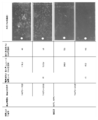
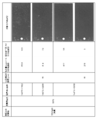
- the figure which shows the principle of the corrosion resistance test which concerns on this embodiment The table which shows the processing conditions of a test materials 1-3, and a corrosion-resistant test result. A table showing the treatment conditions and corrosion resistance test results of test materials 4 to 6.
- attachment on a coating film is water, 5% NaCl (spray), and 5% CaCl spray. 6 is a table showing the amount of water absorption and the occurrence of blistering of the coating when the deposit on the coating is simulated mud.
- FIG. 5 is a table showing the amount of water absorption and the occurrence of blistering of the coating when the deposit on the coating is 5% NaCl (immersed).
- the graph which shows the relationship between the corrosion suppression period which concerns on the various-film top deposits, and the infiltration speed of the water to a coating.
- FIG. 1 shows the corrosion test principle.
- 1 is a coated metal material.
- the coated metal material 1 according to the present embodiment is a resin coating film as a surface treatment film on the steel plate 2 having the chemical conversion film 3 formed on the surface as a metal base, that is, an electrodeposition coating film in the present embodiment. 4 is provided.
- the corrosion resistance test apparatus comprises an external circuit 7 for electrically connecting the two artificial wounds 5 of the coated metal material 1 via the water-containing electrolyte material 6 functioning as a conductive material, and the external circuit 7. And a DC constant current source 8 as an energizing means for energizing the steel plate 2.
- a cylinder 11 having a diameter larger than that of the artificial wound 5 is provided concentrically with the artificial wound 5 at the two places of the coated metal material 1.
- the water-containing electrolyte material 6 is accommodated in the cylinder 11 and is in contact with the surface of the electrodeposited film 4 and intrudes into the artificial wound 5.
- Electrodes 12 are provided at both ends of the external circuit 7, and the electrodes 12 are provided so as to be embedded in the water-containing electrolyte material 6 in the cylinder 11.
- the water-containing electrolyte material 6 is a mud including water, a clay mineral, and a supporting electrolyte.
- kaolinite which is a layered silicate mineral is adopted as the clay mineral
- three kinds of sodium chloride, sodium sulfate and calcium chloride are adopted as the supporting electrolyte.
- the content of the clay mineral in the water-containing electrolyte material 6 is preferably 1% by mass to 70% by mass, and the content of the supporting electrolyte is preferably 1% by mass to 20% by mass.
- the electrode 12 is a ring-shaped perforated electrode having a through hole 12 a at the center, and is parallel to the electrodeposition coating 4 so that the through hole 12 a faces the artificial wound 5 and is concentric with the artificial wound 5. It is arranged.
- a galvanostat can be employed as the constant current source 8, and the current value is controlled to 10 ⁇ A or more and 10 mA or less.
- An artificial flaw 5 reaching the steel plate 2 is applied through the surface treatment film (the electrodeposition coating film 4 and the chemical conversion film 3) at two separate points of the coated metal material 1.
- the exposed area of the steel plate 2 due to the artificial wound 5 may be 0.005 mm 2 or more and 25 mm 2 or less.
- the distance between the two artificial wounds 5 is preferably 2 cm or more, and more preferably 3 cm or more.
- the indenter tip shape is not limited to a quadrangular pyramid like the indenter of a Vickers hardness tester described later, but various shapes having an appropriate diameter such as a spherical shape can be adopted. .
- a cylinder 11 surrounding each of the two artificial wounds 5 is set on the electrodeposited film 4 of the coated metal material 1, and a predetermined amount of the mud-like hydrated electrolyte material 6 is placed in the cylinder 11.
- the ring-shaped perforated electrode 12 of the external circuit 7 provided with the constant current source 8 is buried in the water-containing electrolyte material 6.
- the cylinder 11 is preferably provided concentrically with the artificial wound 5.
- the perforated electrode 12 is preferably provided parallel to the surface of the electrodeposition coating 4 and concentric with the artificial wound 5.
- the water-containing electrolyte material 6 accommodated in the cylinder 11 is in contact with the surface of the electrodeposition coating film 4 and enters the artificial wound 5. Then, the two artificial wound parts are electrically connected by the external circuit 7 through the water-containing electrolyte material 6 in contact with the artificial wound parts.
- the constant current source 8 is operated, and the steel plate 2 of the coated metal material 1 is energized by the external circuit 7 through the perforated electrode 12, the water-containing electrolyte material 6 and the electrodeposited film 4. It is preferable to perform constant current control so that the current value becomes a constant current value of 10 ⁇ A to 10 mA.
- electrons e ⁇ ⁇ flow from the water-containing electrolyte material 6 into the steel plate 2 on the one side (left side in FIG. 1) of the two artificial wound parts connected to the negative electrode side of the constant current source 8.
- One of the artificial wounds is an anode site.
- the e ⁇ which has flowed into the steel plate 2 passes through the steel plate 2 to move to the other artificial wound (right side in FIG. 1), and is released to the water-containing electrolyte material 6 at the other artificial wound.
- the other artificial wound becomes a cathode site.
- Fe of the steel plate 2 becomes ions and dissolves in the water-containing electrolyte material (Fe ⁇ Fe 2+ + 2e ⁇ ) on the same principle as cathodic protection (Fe ⁇ Fe 2+ + 2e ⁇ ). I will not advance.
- a voltage is applied to the water-containing electrolyte material 6 at the cathode site, whereby cations (Na + etc.) in the water-containing electrolyte material 6 pass through the electrodeposition coating 4 to the steel plate 2. Move towards Then, the cation is dragged by the cation and water penetrates into the electrodeposited film 4.
- anions (Cl- and the like) of the water-containing electrolyte material 6 move toward the steel plate 2 through the electrodeposition coating 4 and are dragged by this and water penetrates the electrodeposition coating 4 I will.
- the perforated electrode 12 is disposed so as to surround the artificial wound 5, a voltage is stably applied to the electrodeposited coating 4 around the artificial wound 5. The migration of ions into and the penetration of water are efficiently performed. Further, at the cathode site, where hydrogen gas is generated at the artificial wound 5 as described above, the hydrogen gas passes through the through holes 12 a of the perforated electrode 12, so that the deterioration of the conductivity can be avoided.
- water-containing electrolyte material 6 is a mud containing clay mineral, water and ions can easily penetrate the electrodeposited film 4 around the artificial wound 5.
- the permeation of water and ions into the electrodeposited film 4 around the artificial wound 5 is promoted by the above-described energization, so that the flow of electricity is rapidly stabilized. Therefore, the progress of corrosion from the artificial wound 5 to its surroundings at the cathode site becomes stable.
- Corrosion resistance evaluation step As described above, the progress of corrosion at the cathode site appears as the progress of blistering of the electrodeposition coating film 4, that is, the expansion of the film blistering range. Therefore, the corrosion resistance of the test material can be evaluated by observing the extent to which the coating film bulges when the predetermined time has elapsed from the start of the energization.
- the degree of spread of the coating film blister is obtained by sticking an adhesive tape to the electrodeposited film 4 after the corrosion resistance test, peeling off the bulging part of the electrodeposited film 4, and exposing the diameter of the exposed surface of the steel plate 2 It can be known by measuring the diameter.
- the corrosion resistance test time to see the spread of the coating film swelling may be, for example, 0.5 hours or more and 24 hours or less.
- the test time is preferably 1 hour to 10 hours, more preferably 1 hour to 5 hours.
- Example> Corrosion resistance test- As the test material (coated metal material), six types shown in FIG. 2 and FIG. 3 different in the time of chemical conversion treatment with zinc phosphate and the baking conditions of electrodeposition coating were prepared. In all of the test materials 1 to 6, the metal substrate is the steel plate 2, and the thickness of the electrodeposition coating film 4 is 10 ⁇ m. And about this test material, this corrosion resistance test was done in the aspect shown in FIG.
- test material a square pyramid having a diagonal length of 1 mm reaching the steel plate at a load (test force) of 30 kg quantitatively using a Vickers hardness tester in which the shape of the indenter tip is a square pyramid
- the artificial wound 5 (the exposed area of the steel plate 2 is 0.54 mm 2 ) was given to two places at intervals of 4 cm.
- the opening area of the artificial wound 5 opened on the surface of the test material is 0.5 mm 2 corresponding to the area of the bottom.
- the exposed surface of the steel plate 2 due to the square pyramid artificial wound 5 is a pyramidal surface, the exposed area of the steel plate 2 is 0.54 mm 2 which is larger than the opening area.
- simulated mud of pH 7 was used after being diluted by 20% with 5% brine (sodium chloride).
- a ring-shaped perforated electrode (made of platinum) having an outer diameter of about 32 mm and an inner diameter of about 30 mm was used.
- the current value of the constant current source 8 was 1 mmA, and electricity was applied for 5 hours under an environment of 50 ° C.
- the baking conditions of the electrodeposition coating film 4 become better (the baking temperature becomes high, or the baking time) Is longer, that is, as the film quality of the electrodeposited film 4 is better, the corrosion progress rate in the present corrosion resistance test is slower (the swelling diameter is smaller). That is, the corrosion progress rate corresponds to the quality of the film quality of the electrodeposition coating film 4.
- the corrosion progress rate in this corrosion resistance test is slower in the test material 6 having a longer conversion treatment time (expansion diameter Is small). That is, the corrosion progress rate corresponds to the quality of the chemical conversion film.
- the chemical conversion treatment time of the test material 3 having a chemical conversion treatment time of 30 seconds is 120
- the corrosion progress rate is slower than that of the test material 4 which is a second.
- the test material 3 is slower than the test material 4, so there is no problem with this corrosion resistance test, and the test material for some reason It is considered that the film quality of the electrodeposited film 4 or the chemical conversion film 3 of No. 3 became better than that of the test material 4.
- the water absorption amount is small even after the passage of 9 days for all of water, 5% NaCl (spray) and 5% CaCl (spray), and no blistering of the coating is observed.
- FIG. 8 shows the corrosion suppression period and the penetration speed of water into the coating film in the case where the baking condition of the electrodeposition coating film 4 is 150 ° C. ⁇ 20 minutes for the above five types.
- the time until the blister occurrence rate reaches 0.5% is taken as the corrosion suppression period.
- the penetration rate of water into the coating is calculated from the time until the water absorption of the coating reaches 25 ⁇ g / mm 3 . According to the figure, it can be seen that, in the case of simulated mud, the corrosion suppression period is short, that is, the rate of water penetration into the coating is large, as compared to a salt spray and the like.
- energization to the metal base material (steel plate) 2 is not limited to the constant current control method, but may be a constant voltage control method.
- FIG. 9 is a current plot of energization by constant current control of 1 mA
- FIG. 10 is a current plot when a constant voltage to which 1 mA of current flows is applied.
- the other test conditions are the same except for the conduction condition.
- the current value is controlled to about 1 mA although the current value varies somewhat at the beginning of energization.
- the acceleration repeatability of corrosion is improved. That is, the reliability of the corrosion resistance test is enhanced.
- the current value largely fluctuates, and it can be seen that it is disadvantageous in terms of acceleration reproducibility of corrosion.
- the period in which the fluctuation of the current value from the start of energization to around 7,000 seconds is large corresponds to the period in which water penetrates the electrodeposited film 4 and the permeation of water into the coating does not steadily progress, so the current value is large. It is considered to be fluctuating. Even after that, the current value fluctuates in the range of 0.5 mA to 1.5 mA, which is recognized as the influence of the fluctuation of the resistance value due to the deterioration of the chemical conversion film and the rusting.
Landscapes
- Life Sciences & Earth Sciences (AREA)
- Biodiversity & Conservation Biology (AREA)
- Ecology (AREA)
- Environmental & Geological Engineering (AREA)
- Environmental Sciences (AREA)
- Physics & Mathematics (AREA)
- Health & Medical Sciences (AREA)
- Chemical & Material Sciences (AREA)
- Analytical Chemistry (AREA)
- Biochemistry (AREA)
- General Health & Medical Sciences (AREA)
- General Physics & Mathematics (AREA)
- Immunology (AREA)
- Pathology (AREA)
- Testing Resistance To Weather, Investigating Materials By Mechanical Methods (AREA)
Abstract
被覆金属材の耐食性試験方法は、表面処理膜4の傷に起因して進行する腐食を模擬した電気化学的方法である。金属製基材2に表面処理膜4が設けられてなる被覆金属材1の相離れた2箇所の人工傷5の部分を、含水電解質材料6を介して外部回路11で電気的に接続し、通電によって、上記2箇所の人工傷部5の一方をアノードサイトとし、他方をカソードサイトとして腐食を進行させる。
Description
本発明は被覆金属材の耐食性試験方法及び耐食性試験装置に関する。
従来より、塗膜性能を評価する手法として複合サイクル試験、塩水噴霧試験等の腐食促進試験が行われている。
しかし、かかる腐食促進試験においては、評価に数ヶ月を要するため、例えば塗装鋼板の構成材料や焼付条件の異なる塗膜の膜質を簡便に評価し、塗装条件の最適化等を迅速に行うことが困難である。従って、材料開発、塗装工場の工程管理、車両防錆に係る品質管理の場において、塗装鋼板の耐食性を迅速且つ簡便に評価する定量評価法の確立が望まれている。
これに対して、特許文献1には、金属部材の表面に施された皮膜の耐食性を評価する手法として、金属部材及び対極部材を水又は電解質液に浸漬し、測定電源の負端子側を金属部材に、正端子側を対極部材に電気的に接続し、対極部材から皮膜を通して金属部材に流れる酸素拡散限界電流に基づいて当該皮膜の防食性能を評価することが記載されている。
特許文献2には、塗装金属材の塗膜表面側に電解質材料を介して電極を配置し、塗装金属材の基材と塗膜表面との間に電圧を印加し、塗膜が絶縁破壊するときの電圧値に基づいて、塗装金属材の耐食性を評価することが記載されている。
特許文献3には、塗装金属材の塗膜表面側に電解質材料を介して電極を配置し、塗装金属材の塗膜に電解質材料を浸透させ、塗装金属材の基材と塗膜表面との間に電圧を印加し、該電圧の印加に伴って流れる電流に関する値に基づき、塗装金属材の耐食性を評価することが記載されている。
特許文献1-3に記載された耐食性試験方法においても、塗装金属材の耐食性を評価することができるが、より信頼性が高い評価結果が得られる耐食性試験の確立が求められる。特に、腐食は金属製基材の表面処理膜の傷に起因して進行することが多いところ、従来、そのような腐食を模擬した簡便で且つ信頼性が高い電気化学的耐食性試験についての報告は見当たらない。
本発明は、当該電気化学的耐食性試験の方法及び装置を提供することを課題とする。
金属の腐食は、水と接触する金属が溶解(イオン化)して遊離電子を生ずるアノード反応(酸化反応)と、その遊離電子によって水中の溶存酸素が水酸基OH-を生成するカソード反応(還元反応)が同時に起こることで進行する、という腐食モデルが知られている。
そこで、本発明は、被覆金属材にアノードサイトとカソードサイトを人工的に形成して腐食を促進させるようにした。
ここに開示する耐食性試験方法は、金属製基材に表面処理膜が設けられてなる被覆金属材を対象とし、
上記被覆金属材の相離れた2箇所に、上記表面処理膜を貫通して上記金属製基材に達する人工傷を加えるステップと、
上記2箇所の人工傷部を、該人工傷部に接触する含水電解質材料を介して外部回路で電気的に接続するステップと、
上記外部回路によって上記金属製基材に通電することにより、上記2箇所の人工傷部の一方をアノードサイトとし、他方をカソードサイトとして、上記被覆金属材の腐食を進行させるステップとを備えていることを特徴とする。
上記被覆金属材の相離れた2箇所に、上記表面処理膜を貫通して上記金属製基材に達する人工傷を加えるステップと、
上記2箇所の人工傷部を、該人工傷部に接触する含水電解質材料を介して外部回路で電気的に接続するステップと、
上記外部回路によって上記金属製基材に通電することにより、上記2箇所の人工傷部の一方をアノードサイトとし、他方をカソードサイトとして、上記被覆金属材の腐食を進行させるステップとを備えていることを特徴とする。
また、ここに開示する金属製基材に表面処理膜が被覆されてなる被覆金属材の耐食性試験装置は、
上記被覆金属材の相離れた2箇所に加えられた、上記表面処理膜を貫通して上記金属製基材に達する人工傷部間を、該人工傷部に接触する含水電解質材料を介して接続する外部回路と、
上記2箇所の人工傷部の一方がアノードサイトとなり、他方がカソードサイトとなって、上記被覆金属材の腐食が進行するように、上記外部回路によって上記金属製基材に通電する通電手段とを備えていることを特徴とする。
上記被覆金属材の相離れた2箇所に加えられた、上記表面処理膜を貫通して上記金属製基材に達する人工傷部間を、該人工傷部に接触する含水電解質材料を介して接続する外部回路と、
上記2箇所の人工傷部の一方がアノードサイトとなり、他方がカソードサイトとなって、上記被覆金属材の腐食が進行するように、上記外部回路によって上記金属製基材に通電する通電手段とを備えていることを特徴とする。
上記方法又は上記装置に係る耐食性試験によれば、被覆金属材の2箇所の人工傷部のうちの一方が、金属製基材の金属の溶出反応(酸化反応)を生ずるアノードサイトとなる。アノードサイトで発生した電子が金属製基材を通って流入する他方の人工傷部が、電子による還元反応が起きるカソードサイトとなる。
アノードサイトでは、溶出した金属イオンは、電極(負極)に引き寄せられ、含水電解質材料中の溶存酸素や電極(負極)での水の電気分解により発生したOH-と反応して水酸化鉄になる。このアノードサイトでは、電子が供給されるから、電気防食と同じ原理で、金属製基材の金属がイオンになって含水電解質材料に多少溶解するものの、被覆金属材の腐食は進まない。
一方、カソードサイトでは、アノードサイトから金属製基材を介して流入する電子が、表面処理膜を浸透した水や溶存酸素、水中の電離H+と反応して水素やOH-が発生する。また、水の電気分解による水素も発生する。これにより、表面処理膜下でのpHが上がり、被覆金属材の腐食が進行する。
上記カソードサイトにおけるOH-の生成は上述の腐食モデルのカソード反応に相当するから、上記耐食性試験は、外部回路による金属製基材への通電により、当該被覆金属材の実際の腐食を加速再現するものであるということができる。
上記2箇所の人工傷部のうちのカソードサイトでは、アルカリ性になること(OH-の生成)により、金属製基材表面の下地処理(化成処理)がダメージを受けて表面処理膜の密着性が低下し(下地処理がされていない場合は単純に金属製基材と表面処理膜の密着性が低下し)、表面処理膜の膨れが発生する。また、水の電気分解やH+の還元により発生した水素ガスが表面処理膜の膨れを促進する。従って、この表面処理膜の膨れの程度をみることによって、当該耐食性試験における供試材の腐食進展速度を計ることができる。
後に実験データに基づいて詳述するが、上記耐食性試験は、上述の如く、実際の腐食を加速再現するから、得られる腐食進展速度データは、実際の腐食進展速度と相関性が高いものになる。よって、当該腐食進展速度データによって、供試材の耐食性について信頼性が高い評価を行なうことができる。
上記含水電解質材料としては、種々のものを採用することができる。一実施形態では、上記含水電解質材料は泥状物であり、上記2箇所の人工傷部各々の上記表面処理膜の表面に設けられる。含水電解質材料が泥状であることにより、人工傷部において水が表面処理膜に浸透し易くなり、腐食が進み易くなる。また、含水電解質材料が泥状であることにより、表面処理膜が水平になっていない場合でも、該表面処理膜の表面に含水電解質材料を設けることができる。
含水電解質材料は、粘土鉱物を添加材として採用することによって泥状物とすることができる。粘土鉱物としては、例えば、層状ケイ酸塩鉱物又はゼオライトを採用することができる。層状ケイ酸塩鉱物としては、カオリナイト、モンモリロナイト、セリサイト、イライト、グローコナイト、クロライト及びタルクから選択される少なくとも一つを好ましく採用することができる。支持電解質(塩)としては、塩化ナトリウム、硫酸ナトリウム、塩化カルシウム、リン酸カルシウム、塩化カリウム、硝酸カリウム、酒石酸水素カリウム及び硫酸マグネシウムから選択される少なくとも一つの塩を好ましく採用することができる。含水電解質材料は、有機溶剤(アセトン、エタノール、トルエン、メタノール等)を含有するものであってもよい。
含水電解質材料における粘土鉱物の含有量は、1質量%以上70質量%以下であることが好ましい。その含有量は、10質量%以上50質量%以下であること、20質量%以上40質量%以下であることがさらに好ましい。
含水電解質材料における支持電解質の含有量は、1質量%以上20質量%以下であることが好ましい。その含有量は、3質量%以上15質量%以下であること、5質量%以上10質量%以下であることがさらに好ましい。
含水電解質材料における有機溶剤の含有量は、水に対して体積比で5%以上60%以下であることが好ましい。その体積比は、10%以上40%以下であること、20%以上30%以下であることがさらに好ましい。
上記金属製基材への通電のために、上記外部回路の両端の電極を上記含水電解質材料に埋没状態に設けることができる。そのような電極としては、炭素電極、白金電極等を使用することができ、特に、上記表面処理膜に相対する少なくとも一つの貫通孔を有する有孔電極を採用することができ、該有孔電極を上記表面処理膜と略平行に配置することが好ましい。例えば、有孔電極は、中央に貫通孔を有するリング状とされ、該貫通孔が上記人工傷に相対するように設けられる。或いは、有孔電極としてメッシュ状の電極を採用し、該メッシュ電極を上記含水電解質材料に埋没した状態で上記表面処理膜と略平行になるように配置してもよい。
上記人工傷は、表面処理膜を貫通して金属製基材に達する限り、切り傷、刺し傷、擦り傷などいずれの形態であってもよい。
上記カソードサイトの人工傷の大きさに関しては、表面処理膜における金属製基材の露出面積が小さくなるほど、通電性が低下してカソード反応が進み難くなる。一方、その露出面積が大きくなると、カソード反応が不安定になり、腐食の加速再現性が低下する。実験によれば、上記人工傷による上記金属製基材の露出面積は、0.005mm2以上25mm2以下であることが好ましく、0.05mm2以上4mm2以下であること、更には0.13mm2以上2.25mm2以下であることがさらに好ましい。
上記2箇所の人工傷間の距離は、カソードサイトの表面処理膜の膨れの確認の容易さの観点から、2cm以上であることが好ましく、3cm以上であることがさらに好ましい。
上記外部回路による通電の電流値に関しては、該電流値が小さくなるほど腐食の加速性が低下して試験に長時間を要するようになる。一方、その電流値が大きくなると、腐食反応速度が不安定になり、実際の腐食の進行との相関性が悪くなる。実験によれば、その電流値は、10μA以上10mA以下の電流値とすることが好ましく、100μA以上5mA以下の電流値とすること、或いは500μA以上2mA以下の電流値とすることがさらに好ましい。
当該耐食性試験に供するに適した被覆金属材としては、例えば、金属製基材に表面処理膜として樹脂皮膜、すなわち、塗膜が設けられた塗装金属材がある。
金属製基材は、例えば、家電製品、建材、自動車部品等を構成する鋼材、例えば、冷間圧延鋼板(SPC)、合金化溶融亜鉛めっき鋼板(GA)、高張力鋼板又はホットスタンプ材等であり、或いは軽合金材であってもよい。金属製基材は、表面に化成皮膜(リン酸塩皮膜(例えば、リン酸亜鉛皮膜),クロメート皮膜等)が形成されたものであってもよい。
塗膜としては、例えば、エポキシ樹脂系、アクリル樹脂系等のカチオン電着塗膜(下塗り塗膜)があり、電着塗膜に上塗り塗膜が重ねられた積層塗膜、電着塗膜に中塗り塗膜及び上塗り塗膜が重ねられた積層塗膜等であってもよい。
本発明によれば、被覆金属材の相離れた2箇所の人工傷部を、含水電解質材料を介して外部回路で電気的に接続し、通電によって、上記2箇所の人工傷部の一方をアノードサイトとし、他方をカソードサイトとして腐食を進行させるから、当該耐食性試験によって、当該被覆金属材の実際の腐食を加速再現することができ、耐食性について信頼性が高い評価を行なうことができる。
以下、本発明を実施するための形態を図面に基づいて説明する。以下の好ましい実施形態の説明は、本質的に例示に過ぎず、本発明、その適用物或いはその用途を制限することを意図するものではない。
図1は腐食試験原理を示す。同図において、1は被覆金属材である。本実施形態に係る被覆金属材1は、金属製基材としての表面に化成皮膜3が形成された鋼板2の上に表面処理膜としての樹脂塗膜、すなわち、本実施形態では電着塗膜4が設けられたものである。
被覆金属材1には、相離れた2箇所に電着塗膜4及び化成皮膜3を貫通して鋼板2に達する人工傷5が加えられている。
<耐食性試験装置>
本実施形態に係る耐食性試験装置は、導電材として機能する含水電解質材料6を介して被覆金属材1の上記2箇所の人工傷5部分を電気的に接続する外部回路7と、該外部回路7によって上記鋼板2に通電する通電手段としての直流の定電流源8とを備えてなる。
本実施形態に係る耐食性試験装置は、導電材として機能する含水電解質材料6を介して被覆金属材1の上記2箇所の人工傷5部分を電気的に接続する外部回路7と、該外部回路7によって上記鋼板2に通電する通電手段としての直流の定電流源8とを備えてなる。
被覆金属材1の当該2箇所には、人工傷5よりも大径の円筒11が人工傷5と同心状に設けられている。含水電解質材料6は、円筒11内に収容され、電着塗膜4の表面に接触しているとともに、人工傷5内に浸入している。外部回路7の両端には電極12が設けられ、その電極12は円筒11内の含水電解質材料6に埋没状態に設けられている。
含水電解質材料6は、水、粘土鉱物及び支持電解質を含有してなる泥状物である。本実施形態では、粘土鉱物として、層状ケイ酸塩鉱物であるカオリナイトを採用し、支持電解質として、塩化ナトリウム、硫酸ナトリウム及び塩化カルシウムの3種を採用している。含水電解質材料6における粘土鉱物の含有量は1質量%以上70質量%以下であることが好ましく、支持電解質の含有量は1質量%以上20質量%以下であることが好ましい。
電極12は、中央に貫通孔12aを有するリング状の有孔電極であり、該貫通孔12aが人工傷5に相対し該人工傷5と同心になるように、電着塗膜4と平行に配置されている。
定電流源8としては、例えば、ガルバノスタットを採用することができ、電流値は10μA以上10mA以下に制御される。
<耐食性試験方法>
上記耐食性試験装置を用いる被覆金属材1の耐食性試験方法をステップ順に説明する。
上記耐食性試験装置を用いる被覆金属材1の耐食性試験方法をステップ順に説明する。
-人工傷を加えるステップ-
被覆金属材1の相離れた2箇所に表面処理膜(電着塗膜4及び化成皮膜3)を貫通して鋼板2に達する人工傷5を加える。人工傷5による鋼板2の露出面積は0.005mm2以上25mm2以下とすればよい。人工傷を付ける道具の種類は特に問わない。人工傷5の大きさや深さにばらつきを生じないように、すなわち、定量的に傷を付けるために、例えば、ビッカース硬さ試験機を用い、その圧子によって所定荷重で傷を付けることが好ましい。2箇所の人工傷5間の距離は2cm以上とすること、さらには3cm以上とすることが好ましい。
被覆金属材1の相離れた2箇所に表面処理膜(電着塗膜4及び化成皮膜3)を貫通して鋼板2に達する人工傷5を加える。人工傷5による鋼板2の露出面積は0.005mm2以上25mm2以下とすればよい。人工傷を付ける道具の種類は特に問わない。人工傷5の大きさや深さにばらつきを生じないように、すなわち、定量的に傷を付けるために、例えば、ビッカース硬さ試験機を用い、その圧子によって所定荷重で傷を付けることが好ましい。2箇所の人工傷5間の距離は2cm以上とすること、さらには3cm以上とすることが好ましい。
圧子によって人工傷を付ける場合、その圧子先端形状としては、後述するビッカース硬さ試験機の圧子のような四角錐に限らず、球面形状など適宜の径を有する種々の形状を採用することができる。
-外部回路接続ステップ-
被覆金属材1の電着塗膜4の上に、2箇所の人工傷5各々を囲む円筒11を立て、円筒11の中に泥状の含水電解質材料6を所定量入れる。このとき、定電流源8を備えた外部回路7のリング状有孔電極12が含水電解質材料6に埋没した状態になるようにする。円筒11は人工傷5と同心に設けることが好ましい。有孔電極12は、電着塗膜4の表面と平行になるように、且つ人工傷5と同心になるように設けることが好ましい。
被覆金属材1の電着塗膜4の上に、2箇所の人工傷5各々を囲む円筒11を立て、円筒11の中に泥状の含水電解質材料6を所定量入れる。このとき、定電流源8を備えた外部回路7のリング状有孔電極12が含水電解質材料6に埋没した状態になるようにする。円筒11は人工傷5と同心に設けることが好ましい。有孔電極12は、電着塗膜4の表面と平行になるように、且つ人工傷5と同心になるように設けることが好ましい。
以上により、円筒11内に収容された含水電解質材料6が電着塗膜4の表面に接触しているとともに、人工傷5内に浸入した状態になる。そして、上記2箇所の人工傷部が、該人工傷部に接触する含水電解質材料6を介して外部回路7で電気的に接続された状態になる。
-通電ステップ-
定電流源8を作動させ、外部回路7によって被覆金属材1の鋼板2に有孔電極12、含水電解質材料6及び電着塗膜4を介して通電する。この通電は、電流値が10μA以上10mA以下の定電流値となるように定電流制御することが好ましい。
定電流源8を作動させ、外部回路7によって被覆金属材1の鋼板2に有孔電極12、含水電解質材料6及び電着塗膜4を介して通電する。この通電は、電流値が10μA以上10mA以下の定電流値となるように定電流制御することが好ましい。
上記通電により、上記2箇所の人工傷部のうちの定電流源8の負極側に接続された一方(図1の左側)では、含水電解質材料6から電子e-が鋼板2に流入する。この一方の人工傷部がアノードサイトになる。鋼板2に流入したe-は鋼板2を通って他方の人工傷部(図1の右側)に移動し、該他方の人工傷部において含水電解質材料6に放出される。この他方の人工傷部がカソードサイトになる。
アノードサイトでは、e-が供給されるから、電気防食と同じ原理で、鋼板2のFeがイオンになって含水電解質材料に溶解する(Fe → Fe2++2e-)ものの、被覆金属材1の腐食は進まない。
これに対して、カソードサイトでは、アノードサイトから電子が移動してくるから、含水電解質材料6の水、溶存酸素及び当該電子e-の反応によりOH-を生ずる(H2O+1/2O2+2e- → 2OH-)。また、含水電解質材料6の電離した水素イオンと当該電子e-の反応により水素が発生する(2H++2e- → H2)。OH-及び水素の生成はカソード反応(還元反応)である。また、水の電気分解による水素も発生する。
カソードサイトでは、アルカリ性になること(OH-の発生)により、化成皮膜3が溶解し、また、鋼板2の腐食が進む(水和酸化鉄の生成)ことで、電着塗膜4の鋼板2に対する付着力が低下する。そして、上記水素ガスの発生によって、電着塗膜4の膨れを生じ、鋼板2の腐食が人工傷5の部位から周囲に進展していく。
また、上記外部回路7による通電では、カソードサイトにおいて、含水電解質材料6に電圧が加わることにより、含水電解質材料6中の陽イオン(Na+等)が電着塗膜4を通って鋼板2に向かって移動する。そして、この陽イオンに引きずられて水が電着塗膜4に浸透していく。また、アノードサイトにおいても、含水電解質材料6の陰イオン(Cl-等)が電着塗膜4を通って鋼板2に向かって移動し、これに引きずられて水が電着塗膜4に浸透していく。
特に、上記実施形態では、有孔電極12が人工傷5を囲むように配置されているから、人工傷5まわりの電着塗膜4に電圧が安定して印加され、該電着塗膜4へのイオンの移動及び水の浸透が効率良く行なわれる。また、カソードサイトでは、人工傷5部分において上述のように水素ガスが発生するところ、この水素ガスは有孔電極12の貫通孔12aを通って抜けるため、通電性が悪化することが避けられる。
また、含水電解質材料6が粘土鉱物を含有する泥状物であるから、水及びイオンが人工傷5まわりの電着塗膜4に浸透し易くなる。
このように、アノードサイト及びカソードサイトにおいて、上記通電により、人工傷5まわりの電着塗膜4への水及びイオンの浸透が促進されるから、電気の流れが速やかに安定した状態になる。よって、カソードサイトにおける人工傷5からその周囲への腐食の進展が安定したものになる。
<耐食性評価ステップ>
上述の如く、カソードサイトにおける腐食の進展は、電着塗膜4の膨れの進展、つまり、塗膜膨れ範囲の拡大となって現れる。従って、上記通電開始から所定時間を経過した時点での塗膜膨れの広がり程度をみることによって、当該供試材の耐食性を評価することができる。
上述の如く、カソードサイトにおける腐食の進展は、電着塗膜4の膨れの進展、つまり、塗膜膨れ範囲の拡大となって現れる。従って、上記通電開始から所定時間を経過した時点での塗膜膨れの広がり程度をみることによって、当該供試材の耐食性を評価することができる。
塗膜膨れの広がりの程度は、耐食性試験後に、電着塗膜4に粘着テープを貼り、電着塗膜4の膨れた部分を剥がし、露出した鋼板2の露出面の径(以下、「剥離径」という。)を測定することによって知ることができる。
塗膜膨れの広がりみるための耐食性試験時間は、例えば、0.5時間以上24時間以下とすればよい。その試験時間は、好ましくは1時間以上10時間以下、より好ましくは1時間以上5時間以下とする。
供試材の耐食性を実腐食試験(塩水噴霧試験)と関連付けて評価する場合は、当該耐食性試験による腐食進展速度(単位時間当たりの塗膜膨れ径の広がり量)と、実腐食試験での腐食進展速度との関係を予め求めておき、当該耐食性試験結果に基づいて、それが実腐食試験においてどの程度の耐食性に相当するかをみることができる。
<実施例>
-耐食性試験-
供試材(被覆金属材)として、リン酸亜鉛による化成処理時間及び電着塗装の焼付条件が異なる図2及び図3に示す6種類を準備した。供試材1~6はいずれも金属製基材が鋼板2であり、電着塗膜4の厚さは10μmである。そして、各供試材について、図1に示す態様で本耐食性試験を行なった。
-耐食性試験-
供試材(被覆金属材)として、リン酸亜鉛による化成処理時間及び電着塗装の焼付条件が異なる図2及び図3に示す6種類を準備した。供試材1~6はいずれも金属製基材が鋼板2であり、電着塗膜4の厚さは10μmである。そして、各供試材について、図1に示す態様で本耐食性試験を行なった。
供試材には、圧子先端部の形状が四角錐であるビッカース硬さ試験機を用いて定量的に、すなわち、荷重(試験力)30kgで鋼板に達する対角線長さが1mmである四角錐の人工傷5(鋼板2の露出面積は0.54mm2)を2箇所に4cmの間隔をあけて付与した。
なお、対角線長さが1mmである四角錐の底面の面積は0.5mm2であるから、供試材の表面に開口する人工傷5の開口面積は当該底面の面積に対応する0.5mm2であるが、四角錐の人口傷5による鋼板2の露出面は錐面になるから、鋼板2の露出面積は上記開口面積よりも大きい0.54mm2になる。
含水電解質材料6としては、pH7の模擬泥を5%塩水(塩化ナトリウム)で20%希釈して用いた。模擬泥の組成は、水:カオリナイト:塩化ナトリウム:硫酸ナトリウム:塩化カルシウム=500:500:25:25:25(質量比)である。
電極12としては、外径約32mm、内径約30mmのリング状の有孔電極(白金製)を用いた。
定電流源8の電流値は1mmAとし、50℃の環境下で5時間通電した。
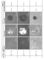
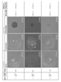
図2及び図3に本耐食性試験結果(アノードサイトの外観、カソードサイトの剥離前と剥離後の外観、腐食進展速度(塗膜の膨れの進展速度)、並びに実腐食試験(傷部に模擬泥を付着させて、温度50℃、湿度98%の環境に暴露する実腐食試験)による腐食進展速度)を示す。
図2及び図3によれば、化成処理時間が120秒である供試材1,4,6をみると、電着塗膜4の焼付条件が良くなる(焼付温度が高くなる、又は焼付け時間が長くなる)ほど、つまり、電着塗膜4の膜質が良くなるほど、本耐食性試験による腐食進展速度が遅く(膨れ径が小さく)なっている。すなわち、当該腐食進展速度は電着塗膜4の膜質の良否に対応している。
電着塗膜4の焼付条件が150℃×20分である供試材5,6をみると、化成処理時間が長い供試材6の方が本耐食性試験による腐食進展速度が遅く(膨れ径が小さく)なっている。すなわち、当該腐食進展速度は化成皮膜の良否に対応している。
なお、電着塗膜4の焼付条件が140℃×20分である供試材2,3,4をみると、化成処理時間が30秒である供試材3の方が化成処理時間が120秒である供試材4よりも当該腐食進展速度が遅くなっている。しかし、実腐食試験による腐食進展速度を見ても、供試材3の方が供試材4よりも遅くなっているから、本耐食性試験に問題があったわけではなく、何らかの原因で供試材3の電着塗膜4又は化成皮膜3の膜質が供試材4よりも良くなったものと考えられる。
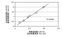
図4に示すように、供試材1~6について、本耐食性試験に係る腐食進展速度と実腐食試験に係る腐食進展速度の相関をみると、その相関が強い(R2=0.9863)ことがわかる。従って、本耐食性試験によって腐食進展速度を測定することにより、被覆金属材1の耐食性について、実腐食試験に匹敵する評価を行なうことができることがわかる。
-含水電解質材料による塗膜の吸水促進性-
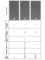
焼付条件又は膜厚が異なる各種電着塗膜4の表面に種々の付着物を設けて、その電着塗膜4の9日経過後の吸水量及び9日経過後の膨れ発生率を調べた。図5~図7に示すように、付着物の種類及び形態は、「水」、「5%NaCl(スプレー)」、「5%CaCl(スプレー)」、上記「模擬泥」及び「5%NaCl(浸漬)」の5種類である。
焼付条件又は膜厚が異なる各種電着塗膜4の表面に種々の付着物を設けて、その電着塗膜4の9日経過後の吸水量及び9日経過後の膨れ発生率を調べた。図5~図7に示すように、付着物の種類及び形態は、「水」、「5%NaCl(スプレー)」、「5%CaCl(スプレー)」、上記「模擬泥」及び「5%NaCl(浸漬)」の5種類である。
図5によれば、水、5%NaCl(スプレー)及び5%CaCl(スプレー)のいずれも、9日経過後でも、吸水量はわずかであり、塗膜の膨れもほとんどみられない。
これに対して、図6によれば、模擬泥の場合は、9日経過後の吸水量及び膨れ発生率が、水、5%NaCl(スプレー)及び5%CaCl(スプレー)に比べると、格段に大きくなっている。特に、電着塗膜4の焼付条件が同じ150℃×20分であるケースで比較すると、模擬泥の場合は、当該吸水量及び膨れ発生率が桁違いに大きくなっていることがわかる。
図7によれば、5%NaCl(浸漬)の場合は、当該吸水量及び膨れ発生率が、水、5%NaCl(スプレー)及び5%CaCl(スプレー)よりも大きくなっているが、図6の標準泥に比べるとかなり低い。
図8は上記5種類について、電着塗膜4の焼付条件が150℃×20分であるケースでの腐食抑制期間と塗膜への水の浸入速度をみたものである。膨れ発生率が0.5%に到達するまでの時間を腐食抑制期間としている。塗膜への水の浸入速度は、塗膜の吸水量が25μg/mmm3に到達するまで時間から計算している。同図によれば、模擬泥の場合、腐食抑制期間が短く、すなわち、塗膜への水の浸入速度が大きいことが塩水スプレー等に比べて格段に大きいことがわかる。
以上から、含水電解質材料6として模擬泥を採用すると、水が塗膜に対して速やかに浸透し、上述の電気化学的手法による耐食性試験を迅速に且つ安定して行なうことができることがわかる。
-通電制御について-
本実施形態に係る耐食性試験において、金属製基材(鋼板)2に対する通電は、定電流制御方式に限らず、定電圧制御方式にすることもできる。
本実施形態に係る耐食性試験において、金属製基材(鋼板)2に対する通電は、定電流制御方式に限らず、定電圧制御方式にすることもできる。
図9は1mAの定電流制御による通電の電流プロットであり、図10は1mAの電流が流れる程度の定電圧を印加したときの電流プロットである。この定電流制御の耐食性試験及び定電圧制御の耐食性試験において、通電条件を除く、他の試験条件は同じである。
定電流制御の場合、電流値が通電初期において多少ばらつくものの、略1mAに制御されている。このように腐食の加速に直接関与する電流値が安定することにより、腐食の加速再現性が良くなる。すなわち、耐食性試験の信頼性が高くなる。
これに対して、定電圧制御の場合、電流値が大きく変動しており、腐食の加速再現性の面で不利になることがわかる。通電開始から7000秒付近までの電流値の変動が大きい期間は、電着塗膜4に水が浸透する期間にあたり、塗膜への水の浸透が定常的に進まないために、電流値が大きく変動しているものと認められる。その後も、電流値は0.5mA~1.5mAの範囲で変動しており、化成皮膜の劣化や発錆に伴う抵抗値の変動の影響と認められる。
定電圧制御での電流プロット(電流波形)から、腐食の進行状態ないしは腐食の程度を捉えることが可能になる。
1 被覆金属材
2 鋼板(金属製基材)
3 化成皮膜
4 電着塗膜(表面処理膜)
5 人工傷
6 含水電解質材料
7 外部回路
8 定電流源(通電手段)
12 電極(有孔電極)
12a 貫通孔
2 鋼板(金属製基材)
3 化成皮膜
4 電着塗膜(表面処理膜)
5 人工傷
6 含水電解質材料
7 外部回路
8 定電流源(通電手段)
12 電極(有孔電極)
12a 貫通孔
Claims (12)
- 金属製基材に表面処理膜が設けられてなる被覆金属材の耐食性試験方法であって、
上記被覆金属材の相離れた2箇所に、上記表面処理膜を貫通して上記金属製基材に達する人工傷を加えるステップと、
上記2箇所の人工傷部を、該人工傷部に接触する含水電解質材料を介して外部回路で電気的に接続するステップと、
上記外部回路によって上記金属製基材に通電することにより、上記2箇所の人工傷部の一方をアノードサイトとし、他方をカソードサイトとして、上記被覆金属材の腐食を進行させるステップとを備えていることを特徴とする被覆金属材の耐食性試験方法。 - 請求項1において、
上記含水電解質材料は、泥状物であり、上記2箇所の人工傷部各々の上記表面処理膜の表面に設けられることを特徴とする被覆金属材の耐食性試験方法。 - 請求項1又は請求項2において、
上記カソード反応を生ずる側の上記人工傷による上記金属製基材の露出面積が0.005mm2以上25mm2以下であることを特徴とする被覆金属材の耐食性試験方法。 - 請求項3において、
上記2箇所の人工傷間の距離が3cm以上であることを特徴とする被覆金属材の耐食性試験方法。 - 請求項1乃至請求項4のいずれか一において、
上記外部回路による通電は10μA以上10mA以下の電流値とすることを特徴とする被覆金属材の耐食性試験方法。 - 請求項1乃至請求項5のいずれか一において、
上記表面処理膜は、樹脂塗膜であることを特徴とする被覆金属材の耐食性試験方法。 - 金属製基材に表面処理膜が被覆されてなる被覆金属材の耐食性試験装置であって、
上記被覆金属材の相離れた2箇所に加えられた、上記表面処理膜を貫通して上記金属製基材に達する人工傷部間を、該人工傷部に接触する含水電解質材料を介して接続する外部回路と、
上記2箇所の人工傷部の一方がアノードサイトとなり、他方がカソードサイトとなって、上記被覆金属材の腐食が進行するように、上記外部回路によって上記金属製基材に通電する通電手段とを備えていることを特徴とする被覆金属材の耐食性試験装置。 - 請求項7において、
上記電解質材料は、泥状物であり、上記2箇所の人工傷部各々の上記表面処理膜の表面に設けられることを特徴とする被覆金属材の耐食性試験装置。 - 請求項7又は請求項8において、
上記カソード反応を生ずる側の上記人工傷による上記金属製基材の露出面積が0.005mm2以上25mm2以下であることを特徴とする被覆金属材の耐食性試験装置。 - 請求項9において、
上記2箇所の人工傷間の距離が3cm以上であることを特徴とする被覆金属材の耐食性試験装置。 - 請求項7乃至請求項10のいずれか一において、
上記外部回路による通電は10μA以上10mA以下の電流値とすることを特徴とする被覆金属材の耐食性試験装置。 - 請求項7至請求項11のいずれか一において、
上記表面処理膜は、樹脂塗膜であることを特徴とする被覆金属材の耐食性試験装置。
Priority Applications (4)
| Application Number | Priority Date | Filing Date | Title |
|---|---|---|---|
| CN201880050709.9A CN111033224B (zh) | 2017-08-04 | 2018-07-30 | 包覆金属材料的耐腐蚀性试验方法和装置 |
| US16/635,160 US11519844B2 (en) | 2017-08-04 | 2018-07-30 | Corrosion resistance test method and corrosion resistance test apparatus for coated metal material |
| JP2019534500A JP6784335B2 (ja) | 2017-08-04 | 2018-07-30 | 被覆金属材の耐食性試験方法及び耐食性試験装置 |
| EP18841516.0A EP3660488B1 (en) | 2017-08-04 | 2018-07-30 | Corrosion resistance test method and corrosion resistance test apparatus for coated metal material |
Applications Claiming Priority (2)
| Application Number | Priority Date | Filing Date | Title |
|---|---|---|---|
| JP2017-151600 | 2017-08-04 | ||
| JP2017151600 | 2017-08-04 |
Publications (1)
| Publication Number | Publication Date |
|---|---|
| WO2019026843A1 true WO2019026843A1 (ja) | 2019-02-07 |
Family
ID=65233845
Family Applications (1)
| Application Number | Title | Priority Date | Filing Date |
|---|---|---|---|
| PCT/JP2018/028447 Ceased WO2019026843A1 (ja) | 2017-08-04 | 2018-07-30 | 被覆金属材の耐食性試験方法及び耐食性試験装置 |
Country Status (5)
| Country | Link |
|---|---|
| US (1) | US11519844B2 (ja) |
| EP (1) | EP3660488B1 (ja) |
| JP (1) | JP6784335B2 (ja) |
| CN (1) | CN111033224B (ja) |
| WO (1) | WO2019026843A1 (ja) |
Cited By (7)
| Publication number | Priority date | Publication date | Assignee | Title |
|---|---|---|---|---|
| US20210010926A1 (en) * | 2017-08-04 | 2021-01-14 | Mazda Motor Corporation | Corrosion resistance test method and corrosion resistance test apparatus for coated metal material |
| EP3896428A1 (en) * | 2020-04-15 | 2021-10-20 | Mazda Motor Corporation | Anticorrosion test method and anticorrosion test equipment for coated metallic material |
| US20210341381A1 (en) * | 2018-09-27 | 2021-11-04 | Nippon Telegraph And Telephone Corporation | Corrosivity Evaluation Device and Method Thereof |
| US20210396648A1 (en) * | 2020-06-22 | 2021-12-23 | Mazda Motor Corporation | Measurement method and measurement device, and corrosion resistance test method and corrosion resistance test apparatus for coated metal material |
| JP2022026202A (ja) * | 2020-07-30 | 2022-02-10 | マツダ株式会社 | 被覆金属材の耐食性試験装置及び耐食性試験方法 |
| US12066374B2 (en) | 2020-06-22 | 2024-08-20 | Mazda Motor Corporation | Measurement method and measurement device, and corrosion resistance test method and corrosion resistance test apparatus for coated metal material |
| US12352683B2 (en) | 2020-06-22 | 2025-07-08 | Mazda Motor Corporation | Damaged portion treatment method and damaged portion treatment device, and corrosion resistance test method and corrosion resistance test apparatus for coated metal material |
Families Citing this family (7)
| Publication number | Priority date | Publication date | Assignee | Title |
|---|---|---|---|---|
| JP6747495B2 (ja) * | 2018-12-11 | 2020-08-26 | マツダ株式会社 | 被覆金属材の耐食性試験方法 |
| JP2020118468A (ja) * | 2019-01-18 | 2020-08-06 | マツダ株式会社 | 被覆金属材の耐食性試験装置 |
| JP6835279B1 (ja) * | 2020-06-22 | 2021-02-24 | マツダ株式会社 | 電極部装置、被覆金属材の耐食性試験方法及び耐食性試験装置 |
| JP7088396B1 (ja) * | 2021-10-01 | 2022-06-21 | マツダ株式会社 | 被覆金属材の耐食性試験方法、耐食性試験装置、耐食性試験用プログラム及び記録媒体 |
| JP7156481B1 (ja) * | 2021-10-01 | 2022-10-19 | マツダ株式会社 | 被覆金属材の耐食性試験方法、耐食性試験装置、耐食性試験用プログラム及び記録媒体 |
| JP2024057391A (ja) * | 2022-10-12 | 2024-04-24 | マツダ株式会社 | 腐食検査用測定装置 |
| CN116626140B (zh) * | 2023-05-31 | 2025-12-19 | 寰泰储能科技股份有限公司 | 材料耐受性测试装置及其使用方法 |
Citations (6)
| Publication number | Priority date | Publication date | Assignee | Title |
|---|---|---|---|---|
| JPS5948649A (ja) * | 1982-09-13 | 1984-03-19 | Nippon Paint Co Ltd | 塗装金属の耐食性評価装置 |
| JPH07234202A (ja) * | 1994-02-23 | 1995-09-05 | Kinki Sharyo Co Ltd | コーティング物の付着性試験方法およびその装置 |
| JP2007271501A (ja) | 2006-03-31 | 2007-10-18 | Osaka Gas Co Ltd | 被膜の防食評価方法 |
| JP2015059745A (ja) * | 2013-09-17 | 2015-03-30 | 公益財団法人鉄道総合技術研究所 | 劣化状態評価装置、劣化状態評価方法及び劣化状態評価プログラム |
| JP2016050915A (ja) | 2014-09-02 | 2016-04-11 | 国立大学法人広島大学 | 塗装金属材の耐食性評価方法及び耐食性評価装置 |
| JP2016050916A (ja) | 2014-09-02 | 2016-04-11 | マツダ株式会社 | 塗装金属材の耐食性評価方法及び耐食性評価装置 |
Family Cites Families (34)
| Publication number | Priority date | Publication date | Assignee | Title |
|---|---|---|---|---|
| JPS55149049A (en) * | 1979-05-10 | 1980-11-20 | Nippon Paint Co Ltd | Testing method for corrosion evaluation of coated metal material and its apparatus |
| GB2048491B (en) * | 1980-03-17 | 1983-08-03 | Nippon Paint Co Ltd | Method for evaluating corrosion of coated metallic material |
| US4515643A (en) * | 1982-10-22 | 1985-05-07 | Henkel Kommanditgesellschaft Auf Aktien | Method for determining and adjusting the potency and effectiveness of a metal phosphate conversion coating process |
| JPH04120453A (ja) * | 1990-09-12 | 1992-04-21 | Nippon Parkerizing Co Ltd | 塗装膜を施したアルミ缶胴またはアルミ缶蓋の耐食性試験方法 |
| EP0591802A3 (en) * | 1992-09-28 | 1994-06-08 | Hitachi Ltd | Method and apparatus for measuring degree of corrosion of metal materials |
| JP3143780B2 (ja) * | 1996-06-10 | 2001-03-07 | 本田技研工業株式会社 | 金属素材と塗膜とよりなる試験体の耐食試験法および電解試験機 |
| US6365034B1 (en) * | 1997-05-07 | 2002-04-02 | Polymer Alloys Llc | High throughput electrochemical test for measuring corrosion resistance |
| JP3821004B2 (ja) * | 2002-02-08 | 2006-09-13 | スズキ株式会社 | 犠牲陽極の検査方法及び検査装置 |
| US7776606B2 (en) * | 2006-03-03 | 2010-08-17 | Concurrent Technologies Corporation | Processes to create discrete corrosion defects on substrates and establish corrosion NDI test standards |
| FR2917519A1 (fr) * | 2006-09-27 | 2008-12-19 | Peugeot Citroen Automobiles Sa | Procede d'estimation de la corrosion |
| JP5108844B2 (ja) * | 2009-05-12 | 2012-12-26 | 住友電気工業株式会社 | 腐食試験方法 |
| WO2010078548A1 (en) * | 2009-01-02 | 2010-07-08 | E. I. Du Pont De Nemours And Company | Corrosion resistance evaluator |
| WO2012088335A2 (en) * | 2010-12-21 | 2012-06-28 | E. I. Du Pont De Nemours And Company | Corrosion resistance evaluator |
| CN103534573A (zh) * | 2010-12-21 | 2014-01-22 | 涂层国外知识产权有限公司 | 耐腐蚀性的评估方法 |
| JP5830910B2 (ja) * | 2011-04-12 | 2015-12-09 | Jfeスチール株式会社 | 缶成型体の内容物に対する耐腐食性を評価する方法 |
| CN104911687A (zh) * | 2015-07-07 | 2015-09-16 | 安科工程技术研究院(北京)有限公司 | 埋地管道防腐层阴极剥离试验的方法和装置 |
| CN111033224B (zh) * | 2017-08-04 | 2022-08-05 | 马自达汽车株式会社 | 包覆金属材料的耐腐蚀性试验方法和装置 |
| JP6565979B2 (ja) * | 2017-08-04 | 2019-08-28 | マツダ株式会社 | 被覆金属材の耐食性試験装置及び耐食性試験方法 |
| CN108548775A (zh) * | 2018-04-20 | 2018-09-18 | 攀枝花学院 | 搪瓷涂层电极及制备方法、耐腐蚀性测试方法 |
| JP6747495B2 (ja) * | 2018-12-11 | 2020-08-26 | マツダ株式会社 | 被覆金属材の耐食性試験方法 |
| JP2020118468A (ja) * | 2019-01-18 | 2020-08-06 | マツダ株式会社 | 被覆金属材の耐食性試験装置 |
| CN110044810B (zh) * | 2019-03-28 | 2021-12-31 | 中国船舶重工集团公司第七二五研究所 | 一种用于模拟深海环境下缝隙腐蚀研究的人工缝隙装置 |
| JP6733844B1 (ja) * | 2020-04-15 | 2020-08-05 | マツダ株式会社 | 被覆金属材の耐食性試験方法及び耐食性試験装置 |
| JP6835280B1 (ja) * | 2020-06-22 | 2021-02-24 | マツダ株式会社 | 傷の処理方法及び処理装置、並びに、被覆金属材の耐食性試験方法及び耐食性試験装置 |
| CN111879695A (zh) * | 2020-06-22 | 2020-11-03 | 北京科技大学 | 一种涂层失效的实时监测方法及腐蚀监测传感器 |
| JP6835281B1 (ja) * | 2020-06-22 | 2021-02-24 | マツダ株式会社 | 計測方法及び計測装置、並びに、被覆金属材の耐食性試験方法及び耐食性試験装置 |
| JP6801805B1 (ja) * | 2020-06-22 | 2020-12-16 | マツダ株式会社 | 計測方法及び計測装置、並びに、被覆金属材の耐食性試験方法及び耐食性試験装置 |
| JP6835279B1 (ja) * | 2020-06-22 | 2021-02-24 | マツダ株式会社 | 電極部装置、被覆金属材の耐食性試験方法及び耐食性試験装置 |
| JP6849140B1 (ja) * | 2020-07-30 | 2021-03-24 | マツダ株式会社 | 被覆金属材の耐食性試験装置及び耐食性試験方法 |
| CN112147021B (zh) * | 2020-08-10 | 2022-07-29 | 中国船舶重工集团公司第七二五研究所 | 一种金属钝化膜消长动态过程的电化学测试装置 |
| JP6835287B1 (ja) * | 2020-09-29 | 2021-02-24 | マツダ株式会社 | 被覆金属材の耐食性試験方法及び該方法に用いられる含水材料 |
| JP6835286B1 (ja) * | 2020-09-29 | 2021-02-24 | マツダ株式会社 | 被覆金属材の耐食性試験方法及び該方法に用いられる含水材料 |
| CN113777013B (zh) * | 2021-06-23 | 2023-11-21 | 武汉钢铁有限公司 | 一种耐蚀性试验样片及锌铝镁镀层钢耐蚀性能的测试方法 |
| CN113588417A (zh) * | 2021-06-24 | 2021-11-02 | 中国特种设备检测研究院 | 一种腐蚀环境下的金属涂层应力腐蚀测试方法及装置 |
-
2018
- 2018-07-30 CN CN201880050709.9A patent/CN111033224B/zh active Active
- 2018-07-30 US US16/635,160 patent/US11519844B2/en active Active
- 2018-07-30 WO PCT/JP2018/028447 patent/WO2019026843A1/ja not_active Ceased
- 2018-07-30 JP JP2019534500A patent/JP6784335B2/ja active Active
- 2018-07-30 EP EP18841516.0A patent/EP3660488B1/en active Active
Patent Citations (6)
| Publication number | Priority date | Publication date | Assignee | Title |
|---|---|---|---|---|
| JPS5948649A (ja) * | 1982-09-13 | 1984-03-19 | Nippon Paint Co Ltd | 塗装金属の耐食性評価装置 |
| JPH07234202A (ja) * | 1994-02-23 | 1995-09-05 | Kinki Sharyo Co Ltd | コーティング物の付着性試験方法およびその装置 |
| JP2007271501A (ja) | 2006-03-31 | 2007-10-18 | Osaka Gas Co Ltd | 被膜の防食評価方法 |
| JP2015059745A (ja) * | 2013-09-17 | 2015-03-30 | 公益財団法人鉄道総合技術研究所 | 劣化状態評価装置、劣化状態評価方法及び劣化状態評価プログラム |
| JP2016050915A (ja) | 2014-09-02 | 2016-04-11 | 国立大学法人広島大学 | 塗装金属材の耐食性評価方法及び耐食性評価装置 |
| JP2016050916A (ja) | 2014-09-02 | 2016-04-11 | マツダ株式会社 | 塗装金属材の耐食性評価方法及び耐食性評価装置 |
Non-Patent Citations (1)
| Title |
|---|
| See also references of EP3660488A4 |
Cited By (9)
| Publication number | Priority date | Publication date | Assignee | Title |
|---|---|---|---|---|
| US20210010926A1 (en) * | 2017-08-04 | 2021-01-14 | Mazda Motor Corporation | Corrosion resistance test method and corrosion resistance test apparatus for coated metal material |
| US11519844B2 (en) * | 2017-08-04 | 2022-12-06 | Mazda Motor Corporation | Corrosion resistance test method and corrosion resistance test apparatus for coated metal material |
| US20210341381A1 (en) * | 2018-09-27 | 2021-11-04 | Nippon Telegraph And Telephone Corporation | Corrosivity Evaluation Device and Method Thereof |
| EP3896428A1 (en) * | 2020-04-15 | 2021-10-20 | Mazda Motor Corporation | Anticorrosion test method and anticorrosion test equipment for coated metallic material |
| US20210396648A1 (en) * | 2020-06-22 | 2021-12-23 | Mazda Motor Corporation | Measurement method and measurement device, and corrosion resistance test method and corrosion resistance test apparatus for coated metal material |
| US11709127B2 (en) | 2020-06-22 | 2023-07-25 | Mazda Motor Corporation | Measurement method and measurement device, and corrosion resistance test method and corrosion resistance test apparatus for coated metal material |
| US12066374B2 (en) | 2020-06-22 | 2024-08-20 | Mazda Motor Corporation | Measurement method and measurement device, and corrosion resistance test method and corrosion resistance test apparatus for coated metal material |
| US12352683B2 (en) | 2020-06-22 | 2025-07-08 | Mazda Motor Corporation | Damaged portion treatment method and damaged portion treatment device, and corrosion resistance test method and corrosion resistance test apparatus for coated metal material |
| JP2022026202A (ja) * | 2020-07-30 | 2022-02-10 | マツダ株式会社 | 被覆金属材の耐食性試験装置及び耐食性試験方法 |
Also Published As
| Publication number | Publication date |
|---|---|
| EP3660488B1 (en) | 2023-03-15 |
| EP3660488A4 (en) | 2020-10-07 |
| CN111033224A (zh) | 2020-04-17 |
| US20210010926A1 (en) | 2021-01-14 |
| JPWO2019026843A1 (ja) | 2020-07-09 |
| EP3660488A1 (en) | 2020-06-03 |
| US11519844B2 (en) | 2022-12-06 |
| CN111033224B (zh) | 2022-08-05 |
| JP6784335B2 (ja) | 2020-11-11 |
Similar Documents
| Publication | Publication Date | Title |
|---|---|---|
| WO2019026843A1 (ja) | 被覆金属材の耐食性試験方法及び耐食性試験装置 | |
| JP6515963B2 (ja) | 被覆金属材の耐食性試験方法及び耐食性試験装置 | |
| JP6747495B2 (ja) | 被覆金属材の耐食性試験方法 | |
| JP6565980B2 (ja) | 被覆金属材の耐食性試験装置及び被覆金属材の耐食性試験方法 | |
| JP6565979B2 (ja) | 被覆金属材の耐食性試験装置及び耐食性試験方法 | |
| US11566996B2 (en) | Corrosion resistance tester for coated metal material | |
| JP6733844B1 (ja) | 被覆金属材の耐食性試験方法及び耐食性試験装置 | |
| JP6835279B1 (ja) | 電極部装置、被覆金属材の耐食性試験方法及び耐食性試験装置 | |
| JP6835281B1 (ja) | 計測方法及び計測装置、並びに、被覆金属材の耐食性試験方法及び耐食性試験装置 | |
| JP6801805B1 (ja) | 計測方法及び計測装置、並びに、被覆金属材の耐食性試験方法及び耐食性試験装置 | |
| JP6813122B2 (ja) | 被覆金属材の耐食性試験方法 | |
| JP6835280B1 (ja) | 傷の処理方法及び処理装置、並びに、被覆金属材の耐食性試験方法及び耐食性試験装置 | |
| JP7516904B2 (ja) | 被覆金属材の耐食性試験方法及び試験片 | |
| JP2016126011A (ja) | 電磁鋼板の耐食性評価方法 | |
| JP2025152148A (ja) | 被覆金属材の耐食性試験方法、耐食性試験装置、耐食性試験用プログラム及び記録媒体 |
Legal Events
| Date | Code | Title | Description |
|---|---|---|---|
| 121 | Ep: the epo has been informed by wipo that ep was designated in this application |
Ref document number: 18841516 Country of ref document: EP Kind code of ref document: A1 |
|
| ENP | Entry into the national phase |
Ref document number: 2019534500 Country of ref document: JP Kind code of ref document: A |
|
| NENP | Non-entry into the national phase |
Ref country code: DE |
|
| ENP | Entry into the national phase |
Ref document number: 2018841516 Country of ref document: EP Effective date: 20200227 |