WO2019026856A1 - ダーツゲーム装置 - Google Patents
ダーツゲーム装置 Download PDFInfo
- Publication number
- WO2019026856A1 WO2019026856A1 PCT/JP2018/028503 JP2018028503W WO2019026856A1 WO 2019026856 A1 WO2019026856 A1 WO 2019026856A1 JP 2018028503 W JP2018028503 W JP 2018028503W WO 2019026856 A1 WO2019026856 A1 WO 2019026856A1
- Authority
- WO
- WIPO (PCT)
- Prior art keywords
- dart
- light
- dark
- board
- stuck
- Prior art date
- Legal status (The legal status is an assumption and is not a legal conclusion. Google has not performed a legal analysis and makes no representation as to the accuracy of the status listed.)
- Ceased
Links
Images






Classifications
-
- F—MECHANICAL ENGINEERING; LIGHTING; HEATING; WEAPONS; BLASTING
- F41—WEAPONS
- F41J—TARGETS; TARGET RANGES; BULLET CATCHERS
- F41J3/00—Targets for arrows or darts, e.g. for sporting or amusement purposes
- F41J3/02—Indicators or score boards for arrow or dart games
-
- A—HUMAN NECESSITIES
- A63—SPORTS; GAMES; AMUSEMENTS
- A63B—APPARATUS FOR PHYSICAL TRAINING, GYMNASTICS, SWIMMING, CLIMBING, OR FENCING; BALL GAMES; TRAINING EQUIPMENT
- A63B65/00—Implements for throwing ; Mechanical projectors, e.g. using spring force
- A63B65/02—Spears or the like ; Javelins
-
- F—MECHANICAL ENGINEERING; LIGHTING; HEATING; WEAPONS; BLASTING
- F41—WEAPONS
- F41J—TARGETS; TARGET RANGES; BULLET CATCHERS
- F41J3/00—Targets for arrows or darts, e.g. for sporting or amusement purposes
- F41J3/0009—Dartboards
- F41J3/0061—Target faces
-
- F—MECHANICAL ENGINEERING; LIGHTING; HEATING; WEAPONS; BLASTING
- F41—WEAPONS
- F41J—TARGETS; TARGET RANGES; BULLET CATCHERS
- F41J5/00—Target indicating systems; Target-hit or score detecting systems
- F41J5/02—Photo-electric hit-detector systems
-
- F—MECHANICAL ENGINEERING; LIGHTING; HEATING; WEAPONS; BLASTING
- F41—WEAPONS
- F41J—TARGETS; TARGET RANGES; BULLET CATCHERS
- F41J3/00—Targets for arrows or darts, e.g. for sporting or amusement purposes
- F41J3/0009—Dartboards
Definitions
- the present invention relates to a dart game device.
- a light emitting sensor and a light receiving sensor are disposed around a dart board, and a dart game device that detects a blockage of light emitted by the light emitting sensor by the dart stuck in the dart board and calculates a dart position (coordinates) are known (see Patent Document 1).
- Patent Document 2 discloses a technique for calculating the position of a dart by triangulation from the light / dark (shadow of dart) of light based on the dart among the light / dark of light detected by the light sensor.
- the Patent Document 2 also discloses that the positions of all three darts can be calculated by using five light sensors.
- Patent No. 4682986 gazette Japanese Patent Application Publication No. 2001-509251
- FIG. 6 of the present application when five light sensors S1 to S5 are provided at equal intervals on a dart board, an example of calculating positions where three darts are stuck is described.
- the first dart D1 of the first shot is stuck on a line connecting the two photosensors S2 and S4, and the second dart D2 is the other two photosensors S3.
- the dart D3 of the third shot is stuck at the intersection of these lines, the shadow of the dart can be detected with only one light sensor S1.
- the dart's shadow is detected by only one light sensor S1. If it is not possible, the position of the third dart D3 can not be calculated.
- the present invention has been made in view of such problems, and an object thereof is to provide a dart game device capable of calculating the positions of all the darts.
- the dart board includes a plurality of light sensors for detecting light and dark and a processing device for calculating a position where the dart is stuck in the dart board based on the light and dark of the light, and the number of the light sensors is n ⁇ 2.
- the number of light sensors is n ⁇ 2, so n The positions of all darts can be calculated.
- the positions of all the darts can be calculated.
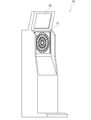
- FIG. 1 is an external perspective view of a dart game device 10 according to a first embodiment of the present invention.
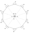
- FIG. 3 is a front view of the dart board 12;
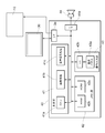
- FIG. 1 shows a block diagram of hardware of a dart game device 10.
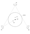
- three light sensors S S1, S2, S3
- S4 four light sensors S (S1, S2, S3 and S4) are provided at equal intervals on the dart board 12
- the respective positions of the three darts D (D1, D2 and D3) are calculated It is a figure explaining an example.
- FIG. 9A is a diagram illustrating an example of a light-dark graph of light when the light sensor S sticks a first dart D, which is a diagram for explaining changes in light-darkness of light detected by the light sensor S.
- FIG. 9 (B) is a diagram showing an example of a light and dark graph of light when the second shot dart D sticks after the first shot S by the light sensor S, and
- FIG. 9 (C) shows the light sensor S
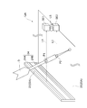
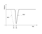
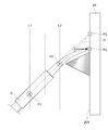
- dart game device 10 of a 1st embodiment of the present invention is a flow chart which shows a flow of processing of CPU41a based on a game program. It is a perspective view of dart board 12A with which the dart game device concerning a 2nd embodiment is provided. It is a figure explaining the structure of the dart board 12A shown in FIG. It is a figure which shows an example of the brightness-and-darkness graph of the light which photosensors SE1 and SE2 detect in a 2nd embodiment. It is a figure for demonstrating calculating the position of the said dart based on the inclination of a dart. It is a graph which shows the relationship between the angle of the dart D, and the distance d.
- FIG. 1 is an external perspective view of a dart game device 10 according to a first embodiment of the present invention.
- the dart game device 10 is formed in, for example, a vertical rectangular parallelepiped shape.
- the dart game device 10 provides players with a dart game in which, for example, one player continuously throws n darts in one round or the like.
- the dart game may include a plurality of game modes in which the number of darts continuously thrown by one player is different according to the rules. In this case, the “n” is the maximum number of darts continuously thrown by one player in each game mode.
- Darts are not particularly limited, such as soft darts and hard darts, but in the first embodiment, the case of soft darts will be described.
- the dart game device 10 includes a dart board 12 and a display device 30.
- the dart board 12 is disposed in the front of the dart game device 10, at a position where the player stands in a substantially line-of-sight position in a standing posture.
- the display device 30 displays a still image or a moving image.
- a coin insertion slot On the front of the dart game device 10, a coin insertion slot, a mode selection switch and the like (not shown) are provided.
- the player puts a fee into the coin insertion slot, presses the mode selection switch to select the game mode, and plays the dart game.
- the player stands at a predetermined position in front of the dart game device 10, and throws a dart aiming at a predetermined target of the dart board 12.
- the tip of the dart board is pierced by the dart board 12, the coordinate position of the pierced dart (hereinafter simply referred to as "position") is detected, and the point is displayed on the display 30 according to the pierced position.
- position the coordinate position of the pierced dart
- FIG. 2 is a front view of the dart board 12.
- the dart board 12 includes a plurality of light sources LS, a plurality of light sensors S, a board body 20, and a frame 22.
- the plurality of light sources LS are attached to the frame 22 at equal intervals, for example. Further, the plurality of light sources LS are arranged around the dart board 12 at substantially the same height from the board surface 20A of the dart board 12 in the board thickness direction.
- the number of light sources LS is, for example, the same as the number of light sensors S.
- the light source LS emits light L in the inward direction of the frame 22.
- the plurality of light sensors S are attached to the frame 22 at equal intervals, for example.
- Each one of the plurality of light sensors S and each one of the plurality of light sources LS are paired, and the pairs of the light sensors S and the light sources LS are provided adjacent to each other in the plate thickness direction.
- Each light sensor S receives the light L emitted from the light source LS and converts the received light L into an electrical signal, thereby detecting the light and dark of the light L at a plurality of angles.
- the number of photosensors S is derived by a theoretical formula described later.
- the board body 20 is formed of, for example, a rectangular plate in a front view.
- a plurality of holes are formed on the surface of the board to be the board 20A so that the dart D can be stuck and engaged.
- the frame 22 surrounds and holds the board main body 20.
- the frame 22 protrudes in the thickness direction of the board main body 20 with respect to the board surface 20A, and forms an inner wall 22A and an outer wall 22B.
- the inner walls 22A of the frame 22 face each other across the board 20A.
- the inner wall 22A facing the light source LS is provided with an opening (not shown) so that the light L can pass through the inside of the frame 22.
- Such an inner wall 22A is provided with a retroreflective material 24 along the circumferential direction of the board body 20.
- the retroreflecting material 24 has a function of reflecting such that when the reflecting surface receives the light L from the light source LS, the light L travels in the direction of the light source LS (for example, the A direction in FIG. 2) again. Have.
- the retroreflecting material 24 has a function of performing reflection such that the intensity of the reflected light is the strongest in the light incident direction.
- the retroreflecting material 24 may be a glass bead reflecting material, a micro prism reflecting material, or the like.
- FIG. 3 shows a block diagram of the dart game device 10 hardware.
- the dart game device 10 includes a control circuit 40.
- the control circuit 40 includes a control unit 41, a memory unit 42, and an operation input unit 43.
- the control unit 41 includes a CPU 41a that controls the entire system, an image processor 41b that performs image processing such as a display position and a size of an image to be displayed on a screen, and an audio signal processor 41c that generates sound. .
- the memory unit 42 includes a ROM 42 a in which programs and data used by the control unit 41 are stored, and a RAM 42 b for temporarily storing various data in the middle of the game. Furthermore, in the operation input unit 43, an operation panel 43a to which various operation signals such as a coin switch for detecting a play fee, a game mode select switch, and a start switch are input is connected to the control unit 41 and the memory unit 42 via the interface 43b. It is done.
- the CPU 41a When the power is turned on, the CPU 41a reads the game program according to the boot program of the ROM 42a, and causes the image processor 41b and the audio signal processor 41c to read the image and audio data stored in the ROM 42a and process the display 30, output video and audio signals to the audio device 44 through the interfaces 3a and 44a.
- the CPU 41a controls the progress of the dart game according to the game program read from the ROM 42a, and advances the game mode desired by the player by the coin insertion signal from the operation input unit 43, the select switch and the input signal from the start switch. .
- the player throws a dart D on the target of the dart board 12 at a predetermined distance from the dart game apparatus 10 and plays the game by stabbing the board 20A of the dart board 12.
- the light and dark of the light L directed to the light sensor S is changed by the dart D shielding the light L, and at least two The light sensor S detects the light and dark of the light, these detection signals are sent to the control unit 41, and the CPU 41 a detects light and dark of the light based on the dart D from the light and dark of the light of the two light sensors S (“ "Peak” or "shadow of dart D" is specified, the direction of the shadow of dart D is specified as, for example, angles ⁇ and ⁇ , and the position where dart D is stuck is calculated by triangulation using angles ⁇ and ⁇ Do.
- the CPU 41a reads the score corresponding to the calculated position from the table stored in the ROM 42a and uses it as the score to cause the image processing processor 41b to display the change in the target video and the score display on the display device 30.
- the sound signal processor 41 c generates a score-up sound and outputs the sound from the sound device 44.
- the control circuit 40 calculates the pierced position from the detection signal from the light sensor S, and the score addition and the sound are output.
- the position where the dart D is stabbed, the score information, the number of stabbed darts D, the number of rounds, etc. are sequentially stored in the RAM 42b, and the game progresses while the image and sound are output based on the data.
- the image processing processor 41b writes the image data to the RAM 42b based on the calculation result of the program, and the written image data is sent to the display device 30 through the interface (I / F) circuit 3a.
- the audio data output from the audio signal processor 41c is also sent to the acoustic device 44 through the interface (I / F) circuit 44a.
- n darts D are stuck on the board 20A of the dart board 12
- a description will be given for deriving a logical expression of the number of light sensors S capable of calculating each position of all the darts D.
- one player sequentially throws three darts D, collects three darts and then recovers the darts D to be replaced by another player.
- four or more (especially four) balls are thrown, for example, in order to decide the player who throws the dart D. Therefore, the above "n” is 3 or more (n) 3). In the following, it is described that one player throws three darts D in succession.
- FIG. 4 shows each position where three darts D (D1, D2, D3) are pierced when three light sensors S (S1, S2, S3) are provided on dartboard 12 at equal intervals. It is a figure explaining the example which calculates.
- the third dart D3 is stuck on the intersection of the line connecting the light sensor S1 and the first dart D1 and the line connecting the light sensor S2 and the second dart D2.
- the shadow of the dart D3 overlaps the shadow of the dart D1 and the shadow of the dart D2 from the light sensor S1 and the light sensor S2 and can not be detected, and can only be detected from the light sensor S3.
- the position of the dart D3 can not be calculated by triangulation.
- the arrangement of the dart D shown in FIG. 4 is changed, for example, when the first dart D1 and the second dart D2 are pierced on the line connecting the light sensor S1 and the light sensor S2, the second dart D2 Can be detected only from the light sensor S3.
- the position of the dart D2 can not be calculated by triangulation. From the above, in the case shown in FIG. 4, only the first dart D ⁇ b> 1 can calculate the position of the dart D by triangulation. Therefore, with the three light sensors S, it is not possible to calculate each position of all the darts D.
- FIG. 5 shows three darts D (D1, D2, D3) stuck in the case where four light sensors S (S1, S2, S3, S4) are provided on the dart board 12 at equal intervals. It is a figure explaining the example which computes a position.
- the first dart D1 sticks in a line connecting the light sensors S2 and S4
- the second dart D2 sticks in a line connecting the light sensors S1 and S3, and the third throw
- the shadow of the third dart D3 can not be detected from any of the light sensors S1 to S4 because it overlaps with the shadow of the dart D1 and the dart D2.
- the position of the dart D can not be calculated by triangulation. From the above, in the case shown in FIG. 5, only the first dart D1 and the second dart D2 can calculate the position of the dart D by triangulation. Therefore, the four light sensors S can not calculate the positions of all the darts D.
- FIG. 6 shows that three darts D (D1, D2, D3) are stuck when five light sensors S (S1, S2, S3, S4, S5) are provided on the dart board 12 at equal intervals. It is a figure explaining the example which calculates each position.
- the first dart D1 is stuck on the line connecting the light sensors S2 and S4
- the second dart D2 is stuck on the line connecting the light sensors S3 and S5
- the third is
- the shadow of the third dart D3 may be detected from the light sensors S2, S3, S4 and S5 by overlapping with the shadow of the dart D1 and the dart D2.
- the position of the third dart D3 is the intersection of the line connecting S2, S4 and the line connecting S3, S5. Although it can be predicted that it is in the vicinity area, it is not possible to know exactly where in the area it is. From the above, in the case shown in FIG. 6, only the first dart D1 and the second dart D2 can calculate the position of the dart D by triangulation. Therefore, with the five light sensors S, it is not possible to calculate each position of all the darts D.
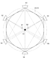
- FIG. 7 shows three darts D (D1, D2, D3) when six light sensors S (S1, S2, S3, S4, S5, S6) are provided on the dart board 12 at equal intervals. It is a figure explaining the example which computes each position which was stuck.
- the first dart D1 sticks in a line connecting the light sensors S2 and S5, the second dart D2 sticks in a line connecting the light sensors S3 and S6, and a third throw
- the shadow of the third dart D3 can be detected from the two light sensors S1 and S4.
- the darts D1 to D3 can calculate the position of the dart D by triangulation. Therefore, each position of all the darts D can be calculated by the six light sensors S.
- FIG. 8 shows an example of calculating positions where five darts D (D1 to D5) are stuck when ten light sensors S (S1 to S10) are provided on the dartboard 12 at equal intervals. It is a figure explaining. As in the example shown in FIG. 8, when the fifth dart D5 is stuck in the center surrounded by the four darts D1 to D4, the shadow of the dart D5 is detected by any of the light sensors S1 to S10. Also, it overlaps with the shadow of any of the darts D1 to D4 (hidden in the shadow) and can not be detected.
- the shadow of this dart D5 similarly overlaps any shadow of darts D1 to D4 from any of the light sensors S (hidden in the shadow), It can not be detected. Therefore, if the number n of darts D to be thrown is five, the shadow of the fifth dart D may not be detected even if the number of light sensors S is increased.
- the number of detectable darts D that can be calculated has an upper limit of four (n ⁇ 4). In the first embodiment, since a dart game in which one or two darts are thrown in one round or the like is not assumed, as a result, the number n of darts D which are continuously thrown in one round or the like is 3 or 4.
- the number of photosensors S is six or eight based on a theoretical formula of 2 ⁇ n.
- FIG. 9 is a view for explaining changes in light and dark of light detected by the light sensor S.
- FIG. 9A is an example of light and dark graph of light when the light sensor S sticks the first dart D
- FIG. 9 (B) is a view showing an example of a light and dark graph of light in the case where the second shot dart D sticks after the first shot by the light sensor S
- FIG. 9 (C) is shown.
- the optical sensor S is composed of a plurality of imaging devices for the necessary resolution, and the imaging devices photoelectrically convert light and dark of light into electric charge, sequentially read out the electric charge, and convert it into an electric signal.
- the imaging devices photoelectrically convert light and dark of light into electric charge, sequentially read out the electric charge, and convert it into an electric signal.
- the vertical axis indicates the light and dark of the light L measured by the light sensor S
- the horizontal axis is an image pickup element sequentially read in the light sensor S
- the position (angle) corresponds to the position (angle) of the light sensor S so that the light sensor S can know at which angle a shadow has occurred.
- the light and dark of the light detected by the light sensor S includes a peak where the light and dark of the light are depressed. This peak shows the shadow of the dart D.
- the position of the dart D is calculated by triangulation based on the angle indicated by the arrow in the drawing at which the center line O of the width of the peak is located.
- the second dart D is stuck adjacent to the first dart D.
- the peak of the second shot dart D is combined with the peak of the first shot dart D, and only one wide peak is detected.
- the angle indicated by the arrow in the figure at which the center line O1 of the width of this peak is located is taken as the angle of the second dart D, and when the position of the second dart D is calculated based on this angle, the calculated position An error may occur between the position of the second dart D and the actual second throw.
- the CPU 41a stores the light and dark of the light detected by the light sensor S in the RAM 42b as a reference when the dart D is stuck on the dart board 12. Then, as shown in FIG. 9C, the CPU 41a calculates the difference between the brightness and darkness of the light detected by the light sensor S and the brightness and darkness of the stored light when the next dart D is stuck in the dart board 12 . Since this difference is the peak (shadow) of only the next dart D, the CPU 41a uses the angle shown by the arrow in the figure as the angle of the second dart D at which the center line of the width of the peak is located, Based on this angle, the position where the second dart D sticks is calculated. This makes it possible to suppress the occurrence of an error between the calculated position and the actual position of the second dart D.
- FIG. 10 is a flow chart showing the flow of processing of the CPU 41a based on the game program in the dart game device 10 of the first embodiment of the present invention.
- Step SP10 The CPU 41a repeats the processing of step SP12 to step SP34 for the number of players who play the dart game.
- Step SP12 When the dart game provided by the dart game device 10 is a game in which n darts D are thrown in one round, the CPU 41a repeats the processing of step SP14 to step SP32 by n.
- the number is three for the game, and the number of players is equal to the number of players before the start of the game.
- Step SP14 The CPU 41a determines whether or not the change button has been pressed based on the presence or absence of the press signal of the change button (not shown). When the CPU 41a makes an affirmative determination, it proceeds to the process of step SP36, and when it makes a negative determination, it proceeds to the process of step SP16.
- Step SP16 The CPU 41a acquires the detection signals of the six light sensors S, that is, the brightness of the light detected by the light sensors S. Then, the CPU 41a proceeds to the process of step SP18.
- Step SP18 The CPU 41a determines whether the dart D has been thrown based on the light and dark of the light of each light sensor S. Specifically, the CPU 41a determines whether or not there is a change in at least two of the light and dark of the light of each light sensor S, and when it is determined that the light and dark of the light change, the dart D If it is determined that the light and dark has no change, it is determined that the dart D is not to be thrown. Then, the CPU 41a increments the total number of darts D thrown when the determination is affirmative, and then proceeds to the process of step SP20, and returns the process of step SP14 when the negative determination is made.
- Step SP20 The CPU 41a determines whether the dart D is the first throw by the player. When the CPU 41a makes an affirmative determination, it proceeds to the process of step SP22, and when it makes a negative determination, it proceeds to the process of step SP26.
- Step SP22 The CPU 41a digitizes the light and dark of each light and stores it in the RAM 42b. Then, the CPU 41a proceeds to the process of step SP24.
- Step SP24 The CPU 41a calculates the position of the dart D by triangulation based on the light and dark of the light based on the dart D (shadow of the dart D) among the light and dark of each light, among the light and dark of the at least two light . Then, the CPU 41a proceeds to the process of step SP32.
- Step SP26 For example, as shown in FIG. 9C, the CPU 41a controls the light and dark of each light currently detected by the light sensor S (bright and dark of the current light) and the light and dark of each light previously detected by the light sensor S (last time Each difference with light and dark) is calculated. Then, the CPU 41a proceeds to the process of step SP28.
- Step SP28 The CPU 41a stores each difference in the RAM 42b. Then, the CPU 41a proceeds to the process of step SP30.
- Step SP30 The CPU 41a calculates the position of the dart D by triangulation based on each difference, in particular, based on the difference between the light and dark of the light based on the dart D among the light and dark of the at least two changed lights. Then, the CPU 41a proceeds to the process of step SP32.
- Step SP32 The CPU 41a calculates the score on the basis of the calculated position of the dart D, and associates the score with the player and stores the score in the RAM 42b, thereby giving the score to the player. Further, based on the calculated score, the CPU 41a causes the display device 30 to reproduce an image or causes the sound device 44 to output a sound, thereby producing a score assignment effect. Then, the CPU 41a proceeds to the process of step SP34.
- Step SP34 The CPU 41a returns to the process of step SP12 until the process of step SP14 to step SP32 is repeated for each of n pieces of darts D, and proceeds to the process of step SP36 when the repeated process is completed.
- Step SP36 The CPU 41a returns to the process of step SP10 until the process of step SP12 to step SP34 is repeated for the number of people, and proceeds to the process of step SP38 when the repeated process is completed.
- Step SP38 The CPU 41a calculates a score total score for each player and, based on each calculated total score, makes a winning / losing decision to decide a winner and a loser among the players. Further, based on the determination of the outcome, the CPU 41a causes the display device 30 to reproduce an image or causes the sound device 44 to output a sound, thereby producing an effect of the outcome determination.
- the number of light sensors S is n ⁇ 2, so n d
- the positions of all the darts D can be calculated.
- the retroreflecting material 24 since the retroreflecting material 24 is provided, the light L emitted from the light source LS can be reflected in the direction of the light source LS, and the reflected light is used to detect the shadow of the dart D. can do.
- the retroreflective member 24 behaves like the light source LS, so the number of light sources LS can be suppressed. If the number of light sources LS can be reduced, the manufacturing cost of the dart game device 10 can be reduced.
- the position where the dart D is stuck is calculated based on the difference between the light and dark of the current light and the light and dark of the previous light, as shown in FIG. Even when adjacent to each other, the position of the dart D can be calculated more accurately.
- a dart game device according to a second embodiment of the present invention will be described.
- the inclination of the dart D with respect to the dart board 12 is calculated, and based on the calculated inclination, the position where the dart D is stuck is calculated. It is different.
- the configuration of the dart game device according to the second embodiment is the same as that of the dart game device 10 according to the first embodiment except for the configuration of the retroreflective member 24 for realizing the calculation of the inclination and the configuration of the optical sensor S.
- FIG. 11 is a perspective view of the dart board 12A provided in the dart game device according to the second embodiment.
- the dart board 12 ⁇ / b> A includes a retroreflective member 24.
- the retroreflector 24 includes two reflectors 24A and 24B spaced apart from the dart board 12A in the thickness direction.
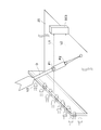
- FIG. 12 is a diagram for explaining the configuration of the dart board 12A shown in FIG.
- the two reflective members 24A and 24B extend in the shape of a strip along the circumferential direction of the board body 20 of the dart board 12A on the inner wall 22A of the frame 22.
- Optical sensors SE1 and SE2 are disposed at both ends of the light source S in the thickness direction from the dart board 12A. That is, the two-step photosensors SE1 and SE2 are disposed in the thickness direction.
- such a combination of light sensors SE1 and SE2 is provided at equal intervals on the dart board 12A, so that a total of 12 light sensors S are arranged in two dimensions.
- the light emitted from the light source LS is reflected by the reflectors 24A and 24B in the direction of the light source LS, and is separated into two light of the light axis L1 and the light of the light axis L2.
- the light sensors SE1 and SE2 detect the light and dark of the passed light. Specifically, the light and dark of the light of the light axis L1 is detected by the light sensor SE1, and the light and dark of the light of the light axis L2 is detected by the light sensor SE2.
- the optical sensors SE1 and SE2 have two points at different distances (heights) from the board 20A per dart D. The respective shadows can be detected for the positions P1 and P2 of.
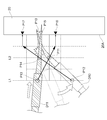
- each of the optical axes L1 and L2 output from the optical sensors SE1 and SE2 The angles of the shadows (peaks) of the two positions P1 and P2 of the dart D are acquired based on light and dark of the light, and the positions P1 and P2 of the two positions of the dart D are calculated based on these angles. Then, the CPU 41a calculates the inclination of the dart D with respect to the dart board 12A based on the calculated positions P1 and P2 of the dart D at two locations.
- the CPU 41a calculates the position of the tip where the dart D is stuck.
- the method of calculating the position of the tip is not particularly limited, for example, as shown in FIG. 14, the CPU 41a calculates the coordinates of the intersection point P3 of the virtual line I1 based on the calculated inclination and the board 20A, It may be determined as the position where D is stuck.
- the tip portion is made of resin, the tip portion is an impact when it is pierced to the board 20A, an influence of weight, or a contact of the adjacent dart D It bends by etc. For this reason, when the coordinates of the intersection point P3 of the virtual line I1 of the inclination of the dart D and the board surface 20A are determined as the position where the dart D is pierced, an error may occur in the actually pierced position.
- the position on the rear end side of the dart D in other words, the position closer to the optical axes L1 and L2 compared to the position of the intersection P1 of the imaginary line I1 of inclination and the board 20A, is the position where the dart D sticks It is preferable to decide. For example, as shown in FIG. 14, since the length of the tip of the dart D to be pierced in the hole can be grasped in advance as a position close to the optical axes L1 and L2, the length of the tip is intersected with P3. It is good also as position P4 which deducted from.
- the characteristic of the dart D specifically, the curvature of bending of the arrow tip portion of the dart D changes depending on the material and thickness of the arrow tip portion, the bending rigidity of the material, and the like. Also, the arrow tip of the dart D is often replaced by the player, and the thickness of the arrow tip portion of the dart D and the bending rigidity of the material are various. Therefore, even if the CPU 41a calculates the bending based on the average thickness of the tip of the arrow, the bending rigidity of the material, etc., and determines the position where the dart D is stuck based on the calculated bending. Good.
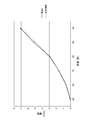
- FIG. 15 is a graph showing the relationship between the angle of the dart D and the distance d.
- the approximate curve shown in FIG. 15 is a quadratic curve.
- the distance d with respect to the angle of the dart D can be approximated by a quadratic curve with the distance d as the vertical axis and the angle of the dart D as the horizontal axis. Since the distance d depends on the thickness and rigidity of the material of the tip portion of the dart D to be used, a quadratic curve (approximate expression) is obtained according to the environment to be used. And the position of the dart D can be determined using this calculated
- the retroreflecting material 24 includes the two reflecting materials 24A and 24B arranged side by side in the thickness direction from the dartboard 12, the light emitted from the light source LS , And light of the optical axis L1 and light of the optical axis L2 can be separated. By using the light and dark of these two lights, in the dart D, it is possible to obtain shadows at positions different in distance from the board 20A.
- the CPU 41a calculates the inclination of the dart D with respect to the dart board 12 based on the light and dark of the two lights, and calculates the position where the dart D is stuck based on the calculated inclination.
- the position of the dart D can be calculated more accurately than when the inclination is not calculated.
- the CPU 41a is positioned at the rear end position P4 of the dart D compared to the position of the intersection point P3 of the virtual line I1 of the dart D along the inclination of the dart D and the board 20A of the dart board 12. Is calculated as the position where the dart D is stuck, the position of the dart D can be calculated more accurately in consideration of the bending of the dart D.
- the present invention is not limited to the above embodiment. That is, those in which a person skilled in the art makes appropriate design changes to the above embodiment are also included in the scope of the present invention as long as they have the features of the present invention. Moreover, each element with which the above-mentioned embodiment is equipped can be combined as much as technically possible, and what combined these is also included in the scope of the present invention as long as the feature of the present invention is included.
- the retroreflective member 24 is provided.
- the retroreflective member 24 may be omitted.
- the position of the dart D may be detected by arranging a plurality of light sources LS around the dart board 12 as in the first embodiment.
- the two-step optical sensors SE1 and SE2 are provided in the plate thickness direction, but instead of these, as shown in FIG. 17, for example, light of the optical axis L1 and the optical axis L2
- the light sensor SE3 may have a width capable of receiving each of the lights.
- the CPU 41a calculates the inclination of the dart D with respect to the dart board 12 based on the two peaks of the dart D. However, in the calculation, the following additional processing is added. May be As further processing, the CPU 41a causes the dart board 12A to stick a new dart D, and when there are a plurality of peaks (shadows of the dart D) in light and dark of one light detected by the light sensor SE1 or SE2, the RAM 42b Identify the current peak of the existing dart from the plurality of peaks based on the stored past peaks of the existing dart D, and calculate the inclination of the dart D based on the identified peaks other than the current peak You may
- the reason for adding the above-mentioned further processing will be described.
- the existing dart D10 and the newly stuck dart D11 may be in contact with each other.
- the tip position P10 of the existing dart D10 stuck to the wall 20A does not move, but the tip end portion of the existing dart D10 bends, thereby moving the rear end positions P11 and P12 of the existing dart D10 It will For this reason, even if the difference between the light and dark of the previous time is taken for the light and dark of the light axis L1 detected by the light sensor SE1, the peak of the existing dart D10 is obtained in addition to the peak based on the position P13 of the new dart D11.
- the CPU 41a identifies and identifies the peak of the position P11 of the existing dart D10 and the peak of the position P12 among the plurality of peaks based on the past peaks of the existing dart D10.
- the correct position P15 can be calculated by calculating the inclination of the new dart D based on the peak other than the peak, that is, the peak at the position P13 and the peak at the position P14.
- SYMBOLS 10 dart game device, 12, 12 A ... dart board, 24 ... retroreflective material, LS ... light source, S, S1-S10, SE1, SE2, SE3 ... optical sensor
Landscapes
- Engineering & Computer Science (AREA)
- General Engineering & Computer Science (AREA)
- Mechanical Engineering (AREA)
- Health & Medical Sciences (AREA)
- General Health & Medical Sciences (AREA)
- Physical Education & Sports Medicine (AREA)
- Aiming, Guidance, Guns With A Light Source, Armor, Camouflage, And Targets (AREA)
- Vending Machines For Individual Products (AREA)
- Control Of Vending Devices And Auxiliary Devices For Vending Devices (AREA)
Abstract
1人の遊戯者が連続してn本(n=3又は4)のダーツDをダーツボード12に投げるダーツゲームを提供するダーツゲーム装置が、ダーツボード12の周囲に配置され、ダーツボード12の盤面に沿って光Lを発する光源LSと、ダーツボード12の周囲においてダーツボード12からそれぞれ板厚方向に略同じ高さに配置され、光源LSから発せられた光Lの光の明暗を検出する複数の光センサSと、各光の明暗に基づき、ダーツボード12においてダーツDが刺さった位置を算出する処理装置と、を備え、光センサSの数がn×2個である。
Description
本出願は、2017年7月31日に出願された日本出願番号2017-148514号に基づくもので、ここにその記載内容を援用する。
本発明は、ダーツゲーム装置に関する。
従来から、ダーツボードの周囲に発光センサと受光センサを配置し、ダーツボードに刺さったダーツによる、発光センサが発した光の遮断を検出して、ダーツの位置(座標)を算出するダーツゲーム装置が知られている(特許文献1参照。)。
これに関し、特許文献2には、光センサが検出する光の明暗のうちダーツに基づく光の明暗(ダーツの影)から、三角測量によりダーツの位置を算出する技術が開示されている。この特許文献2には、5個の光センサを利用することで、3本全てのダーツの位置を算出することが可能である旨も開示されている。
例えば本出願の図6には5個の光センサS1~S5がダーツボードに等間隔に設けられている場合において、3本のダーツが刺さった各位置を算出する事例を説明する図である。5個の光センサS1~S5では、1投目のダーツD1が、ある2個の光センサS2、S4同士を結ぶ線上に刺さり、2投目のダーツD2が、他の2個の光センサS3、S5同士を結ぶ線上に刺さり、3投目のダーツD3が、これらの線の交点に刺さった場合、1個の光センサS1でしかダーツの影を検出することができない。三角測量では、ダーツの影を2個の光センサSから検出できなければ当該ダーツの位置を算出することはできないため、上記のように、1個の光センサS1でしかダーツの影を検出することができないと、3投目のダーツD3の位置は算出することができない。
本発明はこのような課題に鑑みてなされたものであり、その目的は、全てのダーツの位置を算出することができるダーツゲーム装置を提供することにある。
本発明の一態様に係るダーツゲーム装置は、1人の遊戯者が連続してn本(n=3又は4)のダーツを投げるダーツゲームを提供するダーツゲーム装置であって、前記ダーツボードの周囲に配置され、前記ダーツボードの盤面に沿って光を発する光源と、前記ダーツボードの周囲において前記ダーツボードからそれぞれ板厚方向に略同じ高さに配置され、前記光源から発せられた光の明暗を検出する複数の光センサと、前記光の明暗に基づき、前記ダーツボードにおいて前記ダーツが刺さった位置を算出する処理装置とを備え、前記光センサの数がn×2個である。
上記構成によれば、1人の遊戯者が連続してn本(n=3又は4)のダーツを投げるダーツゲームを提供するに際し、光センサの数がn×2個であるので、n本全てのダーツの位置を算出することができる。
本発明によれば、全てのダーツの位置を算出することができる。
以下、添付図面を参照して、本発明の好適な実施形態について説明する。なお、各図において、同一の符号を付したものは、同一又は同様の構成を有する。
―――第1実施形態―――
<全体構成>
図1は、本発明の第1実施形態に係るダーツゲーム装置10の外観斜視図である。
<全体構成>
図1は、本発明の第1実施形態に係るダーツゲーム装置10の外観斜視図である。
図1に示すように、ダーツゲーム装置10は、例えば縦型直方体形状に形成されている。このダーツゲーム装置10は、例えば1ラウンド等で1人の遊戯者が連続してn本のダーツを投げるダーツゲームを遊戯者に提供する。ダーツゲームには、ルールに応じて、1人の遊戯者が連続して投げるダーツの本数が異なる複数のゲームモードを含んでもよい。この場合、上記「n」は、各ゲームモードにおける、1人の遊戯者が連続して投げるダーツの本数のうち、最大となる本数である。ダーツは、ソフトダーツやハードダーツ等特に限定されないが、第1実施形態では、ソフトダーツである場合を説明する。
ダーツゲーム装置10は、ダーツボード12と、表示装置30と、を備える。ダーツボード12は、ダーツゲーム装置10の正面において、遊戯者が立姿勢での略視線位置に配置されている。表示装置30は、静止画像あるいは動画像を表示する。
また、ダーツゲーム装置10の正面には、図示しない硬貨投入口やモード選択スイッチ等が設けられている。遊戯者は、料金を硬貨投入口に投入し、モード選択スイッチを押してゲームモードを選択してダーツゲームを行う。このダーツゲームでは、遊戯者は、ダーツゲーム装置10の手前の所定位置に立ち、ダーツボード12の所定の標的をめがけてダーツを投げる。ダーツボード12に到達したダーツは先端部がダーツボード12に刺さり、刺さったダーツの座標位置(以下、単に「位置」と称す。)が検出され、刺さった位置により得点が表示装置30に表示される。
図2は、ダーツボード12の正面図である。
ダーツボード12は、複数の光源LSと、複数の光センサSと、ボード本体20と、枠体22と、を備える。
複数の光源LSはそれぞれ、枠体22において例えば等間隔に取り付けられている。また、複数の光源LSは、ダーツボード12の周囲においてダーツボード12の盤面20Aからそれぞれ板厚方向に略同じ高さに配置されている。光源LSの個数は、例えば光センサSの個数と同じである。光源LSは、枠体22の内側方向に光Lを発する。
複数の光センサSはそれぞれ、枠体22において例えば等間隔に取り付けられている。複数の光センサSのそれぞれ1個と複数の光源LSのそれぞれ1個をペアとし、光センサSと光源LSのペアは、互いに板厚方向に隣接して設けられている。各光センサSは、光源LSから発せられた光Lを受光し、受光した光Lを電気信号に変換することで、複数の角度において当該光Lの光の明暗を検出する。光センサSの個数は、後述する理論式により導かれる。
ボード本体20は、正面視が例えば四角形状の板で形成されている。盤面20Aとなる板面には、ダーツDが刺さって係合するように不図示の複数の穴が形成されている。
枠体22は、ボード本体20の周囲を囲って保持している。枠体22は、盤面20Aに対して、ボード本体20の板厚方向に突出し、内壁22A及び外壁22Bを形成している。これにより、枠体22の内壁22A同士が、盤面20Aを挟んで互いに対向している。光源LSと対向する内壁22Aには、枠体22内を光Lが通過できるように、不図示の開口が設けられている。
このような内壁22Aには、ボード本体20の周方向に沿って再帰性反射材24が設けられている。再帰性反射材24は、反射面が光源LSから光Lの入射を受けるとその光Lを当該光源LSの方向(例えば図2中のA方向)に向かって再び進行させるような反射する機能を有する。言い換えると、再帰性反射材24は、反射光の強度が、光の入射方向について最も強くなるような反射をする機能を有する。再帰性反射材24としては、ガラスビーズ反射材やマイクロプリズム反射材等がある。
<ハードウェア>
図3は、ダーツゲーム装置10のハードウェアのブロック図を示す。
図3は、ダーツゲーム装置10のハードウェアのブロック図を示す。
図3に示すように、ダーツゲーム装置10は、制御回路40を備えている。制御回路40内は、制御部41、メモリ部42、操作入力部43で構成されている。制御部41は、全体システムを制御するCPU41aと、画面表示しようとする映像の表示位置や大きさ等の画像処理を行う画像処理プロセッサ41bと、音を生成する音声信号処理プロセッサ41cと、を備える。
メモリ部42は、制御部41で使用するプログラムやデータが記憶されたROM42aと、ゲーム途中の各種データを一時記憶するRAM42bとから構成される。さらに操作入力部43は、プレイ代金を検出するコインスイッチやゲームモードのセレクトスイッチ、スタートスイッチ等の各種操作信号が入力される操作パネル43aがインターフェース43bを介して制御部41やメモリ部42に接続されている。
電源が投入されると、CPU41aは、ROM42aのブートプログラムに従い、ゲームプログラムを読み取り、画像処理プロセッサ41b、音声信号処理プロセッサ41cにROM42aに格納された画像と音声のデータを読み取らせ処理して表示装置30、音響装置44に対しインターフェース3a、44aを介して映像信号、音声信号をそれぞれ出力する。
CPU41aは、ROM42aから読み取ったゲームプログラムに従い、ダーツゲームの進行を制御し、操作入力部43からのコイン投入信号、セレクトスイッチ、スタートスイッチからの入力信号により、遊戯者が所望するゲームモードを進行させる。
遊戯者は、ダーツゲーム装置10から所定距離離れてダーツボード12の標的めがけてダーツDを投げ、ダーツボード12の盤面20Aに刺すことでゲームを行う。遊戯者が盤面20Aの標的をめがけて投げたダーツDが盤面20Aに刺さると、ダーツDが光Lを遮蔽することで光センサSに向かう光Lの光の明暗が変化し、少なくとも2個の光センサSが、その光の明暗を検出し、これらの検出信号が制御部41に送られ、CPU41aにより、2個の光センサSの光の明暗からそれぞれ、ダーツDに基づく光の明暗(「ピーク」或いは「ダーツDの影」)を特定し、ダーツDの影の方向を、例えば角度αとβとして特定し、角度αとβを使用した三角測量により、ダーツDが刺さった位置を算出する。
そして、CPU41aは、算出した位置に対応するスコアを、ROM42aに記憶されているテーブルから読み出して得点として、画像処理プロセッサ41bに対し,標的映像の変化や得点表示を表示装置30に表示させるとともに、音声信号処理プロセッサ41cにはスコアアップのサウンドを生成させて音響装置44から出力する。このようにして、光センサSからの検出信号から制御回路40では、刺さった位置を算出し、得点加算及びサウンドが出力される。
ダーツDが刺さった位置や得点情報、刺さったダーツDの本数、ラウンド数等は逐次RAM42bに格納され、そのデータに基づく画像と音声が出力されながらゲームが進行する。画像処理プロセッサ41bは、プログラムの演算結果に基づいて、RAM42bに画像データを書き込み、この書き込まれた画像データはインターフェース(I/F)回路3aを通して、表示装置30へと画像データが送られる。また音声信号処理プロセッサ41cから出力される音声データは、同様にインターフェース(I/F)回路44aを通して音響装置44に送られる。
<光センサSの個数の論理式>
次に、ダーツボード12の盤面20Aにn本のダーツDが刺さった場合に、全てのダーツDの各位置を算出することができる、光センサSの個数の論理式を導くための説明を行う。なお、ダーツゲームにおいては、一般的に、1人の遊戯者が3本のダーツDを順次投げて、3本投げ終わってからダーツDを回収し、他の遊戯者に交代する。また、ダーツDを投げる遊戯者の順番決め等で、4本以上(特に4本)投げる場合がある。したがって、上記「n」は、3以上である(n≧3)。以下では、1人の遊戯者が、連続して3本のダーツDを投げることを説明する。
次に、ダーツボード12の盤面20Aにn本のダーツDが刺さった場合に、全てのダーツDの各位置を算出することができる、光センサSの個数の論理式を導くための説明を行う。なお、ダーツゲームにおいては、一般的に、1人の遊戯者が3本のダーツDを順次投げて、3本投げ終わってからダーツDを回収し、他の遊戯者に交代する。また、ダーツDを投げる遊戯者の順番決め等で、4本以上(特に4本)投げる場合がある。したがって、上記「n」は、3以上である(n≧3)。以下では、1人の遊戯者が、連続して3本のダーツDを投げることを説明する。
まず、三角測量によりダーツDの位置を算出するためには、2個の光センサSからその影が検出できなければならない。この前提を下に、ダーツボード12に設ける光センサSの個数を2個、3個、4個、5個、6個と変化させて、全てのダーツDの各位置を算出することができるか否か説明する。
(2個の光センサSの場合)
2個の光センサSがダーツボード12に等間隔に設けられている場合において、3本のダーツDが刺さった各位置を算出する事例を説明する。
このような事例において、光センサSと1投目のダーツDを結ぶ線上に、2投目のダーツDが刺さった場合、2投目のダーツDの影は、当該光センサSからは1投目のダーツDの影と重なって検出ができない。
以上より、2個の光センサSの場合において、三角測量によりダーツDの位置を算出できるのは、1投目のダーツDのみである。したがって、2個の光センサSでは、全てのダーツDの各位置を算出することはできない。
2個の光センサSがダーツボード12に等間隔に設けられている場合において、3本のダーツDが刺さった各位置を算出する事例を説明する。
このような事例において、光センサSと1投目のダーツDを結ぶ線上に、2投目のダーツDが刺さった場合、2投目のダーツDの影は、当該光センサSからは1投目のダーツDの影と重なって検出ができない。
以上より、2個の光センサSの場合において、三角測量によりダーツDの位置を算出できるのは、1投目のダーツDのみである。したがって、2個の光センサSでは、全てのダーツDの各位置を算出することはできない。
(3個の光センサSの場合)
図4は、3個の光センサS(S1、S2、S3)がダーツボード12に等間隔に設けられている場合において、3本のダーツD(D1、D2、D3)が刺さった各位置を算出する事例を説明する図である。
図4に示す事例のように、光センサS1と1投目のダーツD1を結ぶ線と、光センサS2と2投目のダーツD2を結ぶ線の交点上に3投目のダーツD3が刺さった場合、ダーツD3の影は、光センサS1と光センサS2からはダーツD1の影とダーツD2の影と重なって検出ができず、光センサS3からしか検出できない。これでは、三角測量によりダーツD3の位置を算出することはできない。
また、図4に示すダーツDの配置を変えて、例えば光センサS1と光センサS2を結ぶ線上に1投目のダーツD1と2投目のダーツD2がそれぞれ刺さると、2投目のダーツD2の影は、光センサS3からしか検出できない。これでは、三角測量によりダーツD2の位置を算出することはできない。
以上より、図4に示す事例において、三角測量によりダーツDの位置を算出できるのは、1投目のダーツD1のみである。したがって、3個の光センサSでは、全てのダーツDの各位置を算出することはできない。
図4は、3個の光センサS(S1、S2、S3)がダーツボード12に等間隔に設けられている場合において、3本のダーツD(D1、D2、D3)が刺さった各位置を算出する事例を説明する図である。
図4に示す事例のように、光センサS1と1投目のダーツD1を結ぶ線と、光センサS2と2投目のダーツD2を結ぶ線の交点上に3投目のダーツD3が刺さった場合、ダーツD3の影は、光センサS1と光センサS2からはダーツD1の影とダーツD2の影と重なって検出ができず、光センサS3からしか検出できない。これでは、三角測量によりダーツD3の位置を算出することはできない。
また、図4に示すダーツDの配置を変えて、例えば光センサS1と光センサS2を結ぶ線上に1投目のダーツD1と2投目のダーツD2がそれぞれ刺さると、2投目のダーツD2の影は、光センサS3からしか検出できない。これでは、三角測量によりダーツD2の位置を算出することはできない。
以上より、図4に示す事例において、三角測量によりダーツDの位置を算出できるのは、1投目のダーツD1のみである。したがって、3個の光センサSでは、全てのダーツDの各位置を算出することはできない。
(4個の光センサSの場合)
図5は、4個の光センサS(S1、S2、S3、S4)がダーツボード12に等間隔に設けられている場合において、3本のダーツD(D1、D2、D3)が刺さった各位置を算出する事例を説明する図である。
図5に示す事例のように、1投目のダーツD1が光センサS2、S4同士を結ぶ線上に刺さり、2投目のダーツD2が光センサS1、S3同士を結ぶ線上に刺さり、3投目のダーツD3が上記2つの線の交点上に刺さると、3投目のダーツD3の影は、いずれの光センサS1~S4からもダーツD1とダーツD2の影と重なって検出することができない。これでは、三角測量によりダーツDの位置を算出することはできない。
以上より、図5に示す事例において、三角測量によりダーツDの位置を算出できるのは、1投目のダーツD1と2投目のダーツD2のみである。したがって、4個の光センサSでは、全てのダーツDの各位置を算出することはできない。
図5は、4個の光センサS(S1、S2、S3、S4)がダーツボード12に等間隔に設けられている場合において、3本のダーツD(D1、D2、D3)が刺さった各位置を算出する事例を説明する図である。
図5に示す事例のように、1投目のダーツD1が光センサS2、S4同士を結ぶ線上に刺さり、2投目のダーツD2が光センサS1、S3同士を結ぶ線上に刺さり、3投目のダーツD3が上記2つの線の交点上に刺さると、3投目のダーツD3の影は、いずれの光センサS1~S4からもダーツD1とダーツD2の影と重なって検出することができない。これでは、三角測量によりダーツDの位置を算出することはできない。
以上より、図5に示す事例において、三角測量によりダーツDの位置を算出できるのは、1投目のダーツD1と2投目のダーツD2のみである。したがって、4個の光センサSでは、全てのダーツDの各位置を算出することはできない。
(5個の光センサSの場合)
図6は、5個の光センサS(S1、S2、S3、S4、S5)がダーツボード12に等間隔に設けられている場合において、3本のダーツD(D1、D2、D3)が刺さった各位置を算出する事例を説明する図である。
図6に示す事例のように、1投目のダーツD1が光センサS2、S4同士を結ぶ線上に刺さり、2投目のダーツD2が光センサS3、S5同士を結ぶ線上に刺さり、3投目のダーツD3が上記2つの線の交点上に刺さると、3投目のダーツD3の影は、光センサS2、S3、S4、S5からはダーツD1とダーツD2の影と重なって検出することができず、光センサS1からのみ検出することができる。なお、光センサS1からのみ3投目のダーツD3の影が検出することができると、3投目のダーツD3の位置は、S2、S4同士を結ぶ線とS3、S5同士を結ぶ線の交点付近の領域内であることは予測することはできるが、その領域内のどこの位置であるかまでは正確に把握することができない。 以上より、図6に示す事例において、三角測量によりダーツDの位置を算出できるのは、1投目のダーツD1と2投目のダーツD2のみである。したがって、5個の光センサSでは、全てのダーツDの各位置を算出することはできない。
図6は、5個の光センサS(S1、S2、S3、S4、S5)がダーツボード12に等間隔に設けられている場合において、3本のダーツD(D1、D2、D3)が刺さった各位置を算出する事例を説明する図である。
図6に示す事例のように、1投目のダーツD1が光センサS2、S4同士を結ぶ線上に刺さり、2投目のダーツD2が光センサS3、S5同士を結ぶ線上に刺さり、3投目のダーツD3が上記2つの線の交点上に刺さると、3投目のダーツD3の影は、光センサS2、S3、S4、S5からはダーツD1とダーツD2の影と重なって検出することができず、光センサS1からのみ検出することができる。なお、光センサS1からのみ3投目のダーツD3の影が検出することができると、3投目のダーツD3の位置は、S2、S4同士を結ぶ線とS3、S5同士を結ぶ線の交点付近の領域内であることは予測することはできるが、その領域内のどこの位置であるかまでは正確に把握することができない。 以上より、図6に示す事例において、三角測量によりダーツDの位置を算出できるのは、1投目のダーツD1と2投目のダーツD2のみである。したがって、5個の光センサSでは、全てのダーツDの各位置を算出することはできない。
(6個の光センサSの場合)
図7は、6個の光センサS(S1、S2、S3、S4、S5、S6)がダーツボード12に等間隔に設けられている場合において、3本のダーツD(D1、D2、D3)が刺さった各位置を算出する事例を説明する図である。
図7に示す事例のように、1投目のダーツD1が光センサS2、S5同士を結ぶ線上に刺さり、2投目のダーツD2が光センサS3、S6同士を結ぶ線上に刺さり、3投目のダーツD3が上記2つの線の交点上に刺さると、3投目のダーツD3の影は、2つの光センサS1、S4から検出することができる。
以上より、図7に示す事例において、三角測量によりダーツDの位置を算出できるのは、ダーツD1~D3である。したがって、6個の光センサSでは、全てのダーツDの各位置を算出することができる。
図7は、6個の光センサS(S1、S2、S3、S4、S5、S6)がダーツボード12に等間隔に設けられている場合において、3本のダーツD(D1、D2、D3)が刺さった各位置を算出する事例を説明する図である。
図7に示す事例のように、1投目のダーツD1が光センサS2、S5同士を結ぶ線上に刺さり、2投目のダーツD2が光センサS3、S6同士を結ぶ線上に刺さり、3投目のダーツD3が上記2つの線の交点上に刺さると、3投目のダーツD3の影は、2つの光センサS1、S4から検出することができる。
以上より、図7に示す事例において、三角測量によりダーツDの位置を算出できるのは、ダーツD1~D3である。したがって、6個の光センサSでは、全てのダーツDの各位置を算出することができる。
(まとめ)
以上をまとめると、光センサS同士を結ぶ線上に1投目のダーツD1が刺さり、同一線上に2投目のダーツD2が刺さると、ダーツD2の影は、この線の両端にある2つの光センサSからは、1投目のダーツD1の影と重なり(影に隠れ)、検出することができない。つまり、1投のダーツDによって、後続のダーツDの影を確実に検出できる光センサSの数が、2個が失われる場合が存在する。1本のダーツDの位置を算出するためには、2個の光センサSが必要となるため、光センサS同士を結ぶ線上に1投目が刺さった後、2投目を確実に検出するには、4個の光センサSが必要になる。また、光センサS同士を結ぶ線上に2投目が刺さった後、3投目を確実に検出するには、6個の光センサSが必要になる。
また、連続して投げるダーツDの本数nが4本となる場合、図示はしないものの、3本のダーツDが密集して互いに異なる光センサS同士を結ぶ線上に刺さった場合、4投目を確実に検出するには、6個の光センサSの他に2個の光センサSが必要になる。すなわち、合計8個の光センサSが必要になる。
つまり、ダーツゲームの1ラウンド等で1人の遊戯者が連続して投げるダーツDの本数nに対し、n本のダーツDのそれぞれの位置を算出するためには、2×n個(1≦n)という理論式から導かれる個数の光センサSが必要となる。
以上をまとめると、光センサS同士を結ぶ線上に1投目のダーツD1が刺さり、同一線上に2投目のダーツD2が刺さると、ダーツD2の影は、この線の両端にある2つの光センサSからは、1投目のダーツD1の影と重なり(影に隠れ)、検出することができない。つまり、1投のダーツDによって、後続のダーツDの影を確実に検出できる光センサSの数が、2個が失われる場合が存在する。1本のダーツDの位置を算出するためには、2個の光センサSが必要となるため、光センサS同士を結ぶ線上に1投目が刺さった後、2投目を確実に検出するには、4個の光センサSが必要になる。また、光センサS同士を結ぶ線上に2投目が刺さった後、3投目を確実に検出するには、6個の光センサSが必要になる。
また、連続して投げるダーツDの本数nが4本となる場合、図示はしないものの、3本のダーツDが密集して互いに異なる光センサS同士を結ぶ線上に刺さった場合、4投目を確実に検出するには、6個の光センサSの他に2個の光センサSが必要になる。すなわち、合計8個の光センサSが必要になる。
つまり、ダーツゲームの1ラウンド等で1人の遊戯者が連続して投げるダーツDの本数nに対し、n本のダーツDのそれぞれの位置を算出するためには、2×n個(1≦n)という理論式から導かれる個数の光センサSが必要となる。
ただし、連続して投げるダーツDの本数nが5本となると、光センサSの個数をいくら増やしたとしても、5投目のダーツDの影を検出することができない場合がある。このような場合を、図8を用いて説明する。
図8は、10個の光センサS(S1~S10)がダーツボード12に等間隔に設けられている場合において、5本のダーツD(D1~D5)が刺さった各位置を算出する事例を説明する図である。
図8に示す事例のように、4本のダーツD1~D4で取り囲まれた中央に、5投目のダーツD5が刺さった場合は、ダーツD5の影は、いずれの光センサS1~S10かららもダーツD1~D4の何れかの影と重なり(影に隠れ)、検出することができない。このダーツD5の影は、光センサSの個数を例えば20個に増やしたとしても、同様に、いずれの光センサSかららもダーツD1~D4の何れかの影と重なり(影に隠れ)、検出することができない。したがって、投げるダーツDの本数nが5本となると、光センサSの個数をいくら増やしたとしても、5投目のダーツDの影を検出することができない場合があり、ダーツDの各位置を算出可能な検出可能なダーツDの本数は4本が上限となる(n≦4)。
第1実施形態では、1ラウンド等で1本や2本のダーツを投げるダーツゲームは想定していないので、結果として、1ラウンド等で連続して投げるダーツDの本数nは3又は4であり、光センサSの個数は、2×n個という理論式に基づき、6個又は8個となる。
図8に示す事例のように、4本のダーツD1~D4で取り囲まれた中央に、5投目のダーツD5が刺さった場合は、ダーツD5の影は、いずれの光センサS1~S10かららもダーツD1~D4の何れかの影と重なり(影に隠れ)、検出することができない。このダーツD5の影は、光センサSの個数を例えば20個に増やしたとしても、同様に、いずれの光センサSかららもダーツD1~D4の何れかの影と重なり(影に隠れ)、検出することができない。したがって、投げるダーツDの本数nが5本となると、光センサSの個数をいくら増やしたとしても、5投目のダーツDの影を検出することができない場合があり、ダーツDの各位置を算出可能な検出可能なダーツDの本数は4本が上限となる(n≦4)。
第1実施形態では、1ラウンド等で1本や2本のダーツを投げるダーツゲームは想定していないので、結果として、1ラウンド等で連続して投げるダーツDの本数nは3又は4であり、光センサSの個数は、2×n個という理論式に基づき、6個又は8個となる。
<光の明暗の変化について>
図9は、光センサSが検出する光の明暗の変化を説明する図であって、図9(A)は光センサSが1投目のダーツDが刺さった場合の光の明暗グラフの一例を示す図であり、図9(B)は光センサSが1投目に続いて2投目のダーツDが刺さった場合の光の明暗グラフの一例を示す図であり、図9(C)は光センサSが2投目のダーツDが刺さった後に光の明暗を差分処理した場合の光の明暗グラフの一例を示す図である。なお、光センサSは必要な分解能分の複数の撮像素子からなり、撮像素子は光の明暗を電荷の量に光電変換し、それを順次読み出して電気信号に変換する。ダーツDがダーツボード上に刺さると、その部分の光Lが遮断され、影が生じるので電気信号に変化が生じる。電気信号は光の明暗、すなわち光Lの強度に対応している。図9(A)~(C)に示す光の明暗グラフは、縦軸が光センサSで測定される、光Lの光の明暗を示し、横軸は、光センサSにおいて順次読み出される撮像素子の位置(角度)に対応しており、光センサSから見てどの角度で影が生じたかが判るようになっている。
図9は、光センサSが検出する光の明暗の変化を説明する図であって、図9(A)は光センサSが1投目のダーツDが刺さった場合の光の明暗グラフの一例を示す図であり、図9(B)は光センサSが1投目に続いて2投目のダーツDが刺さった場合の光の明暗グラフの一例を示す図であり、図9(C)は光センサSが2投目のダーツDが刺さった後に光の明暗を差分処理した場合の光の明暗グラフの一例を示す図である。なお、光センサSは必要な分解能分の複数の撮像素子からなり、撮像素子は光の明暗を電荷の量に光電変換し、それを順次読み出して電気信号に変換する。ダーツDがダーツボード上に刺さると、その部分の光Lが遮断され、影が生じるので電気信号に変化が生じる。電気信号は光の明暗、すなわち光Lの強度に対応している。図9(A)~(C)に示す光の明暗グラフは、縦軸が光センサSで測定される、光Lの光の明暗を示し、横軸は、光センサSにおいて順次読み出される撮像素子の位置(角度)に対応しており、光センサSから見てどの角度で影が生じたかが判るようになっている。
図9(A)に示すように、1投目のダーツDが刺さった場合、光センサSが検出する光の明暗には、光の明暗が落ち込んだピークも含まれる。このピークがダーツDの影を示す。このピークの幅の中心線Oが位置する、図中矢印に示す角度に基づき、三角測量により、ダーツDの位置が算出される。
ここで、図2に示すように、2投目のダーツDが1投目のダーツDに隣接して刺さった場合を想定する。この場合、図9(B)に示すように、2投目のダーツDのピークが1投目のダーツDのピークと合わさって、幅の大きい1つのピークのみが検出される。このピークの幅の中央線O1が位置する、図中矢印に示す角度を、2投目のダーツDの角度とし、この角度に基づき、2投目のダーツDの位置を算出すると、算出した位置と、実際の2投目のダーツDの位置との間に誤差が生じ得る。
本実施形態では、CPU41aは、ダーツボード12にダーツDが刺さった場合に光センサSが検出した光の明暗をレファレンスとしてRAM42bに記憶する。そして、CPU41aは、図9(C)に示すように、ダーツボード12に次のダーツDが刺さった場合に光センサSが検出した光の明暗と、記憶した光の明暗との差分を算出する。この差分は、次のダーツDのみのピーク(影)となるので、CPU41aは、当該ピークの幅の中心線が位置する、図中矢印に示す角度を、2投目のダーツDの角度とし、この角度に基づき、2投目のダーツDが刺さった位置を算出する。これにより、算出した位置と、実際の2投目のダーツDの位置との間に誤差が生じることを抑制できる。
<ゲームプログラムに基づく処理>
図10は、本発明の第1実施形態のダーツゲーム装置10において、ゲームプログラムに基づくCPU41aの処理の流れを示すフローチャートである。
図10は、本発明の第1実施形態のダーツゲーム装置10において、ゲームプログラムに基づくCPU41aの処理の流れを示すフローチャートである。
(ステップSP10)
CPU41aは、ダーツゲームを遊戯する遊戯者の人数分、ステップSP12~ステップSP34の処理を繰り返す。
CPU41aは、ダーツゲームを遊戯する遊戯者の人数分、ステップSP12~ステップSP34の処理を繰り返す。
(ステップSP12)
CPU41aは、ダーツゲーム装置10が提供するダーツゲームが、1ラウンドでn本のダーツDを投げるゲームである場合、n本分、ステップSP14~ステップSP32の処理を繰り返す。ゲーム中では3本、ゲーム開始前に遊戯者の投げる順番決めでは人数分の本数となる。
CPU41aは、ダーツゲーム装置10が提供するダーツゲームが、1ラウンドでn本のダーツDを投げるゲームである場合、n本分、ステップSP14~ステップSP32の処理を繰り返す。ゲーム中では3本、ゲーム開始前に遊戯者の投げる順番決めでは人数分の本数となる。
(ステップSP14)
CPU41aは、不図示のチェンジボタンの押下信号の有無に基づき、チェンジボタンが押下されたか否かを判定する。そして、CPU41aは、肯定判定した場合にはステップSP36の処理に進み、否定判定した場合にはステップSP16の処理に進む。
CPU41aは、不図示のチェンジボタンの押下信号の有無に基づき、チェンジボタンが押下されたか否かを判定する。そして、CPU41aは、肯定判定した場合にはステップSP36の処理に進み、否定判定した場合にはステップSP16の処理に進む。
(ステップSP16)
CPU41aは、6個の光センサSからそれぞれの検出信号、すなわち各光センサSが検出した光の明暗を取得する。そして、CPU41aは、ステップSP18の処理に進む。
CPU41aは、6個の光センサSからそれぞれの検出信号、すなわち各光センサSが検出した光の明暗を取得する。そして、CPU41aは、ステップSP18の処理に進む。
(ステップSP18)
CPU41aは、各光センサSの光の明暗に基づき、ダーツDが投げられたか否かを判定する。具体的には、CPU41aは、各光センサSの光の明暗のうち少なくとも2つの光の明暗に変化があるか否かを判定し、光の明暗に変化があると判定した場合にはダーツDが投げられたと肯定判定し、光の明暗に変化がないと判定した場合にはダーツDが投げられていないと否定判定する。そして、CPU41aは、肯定判定した場合には投げられたダーツDの総数をインクリメントした後ステップSP20の処理に進み、否定判定した場合にはステップSP14の処理に戻る。
CPU41aは、各光センサSの光の明暗に基づき、ダーツDが投げられたか否かを判定する。具体的には、CPU41aは、各光センサSの光の明暗のうち少なくとも2つの光の明暗に変化があるか否かを判定し、光の明暗に変化があると判定した場合にはダーツDが投げられたと肯定判定し、光の明暗に変化がないと判定した場合にはダーツDが投げられていないと否定判定する。そして、CPU41aは、肯定判定した場合には投げられたダーツDの総数をインクリメントした後ステップSP20の処理に進み、否定判定した場合にはステップSP14の処理に戻る。
(ステップSP20)
CPU41aは、ダーツDが遊戯者による1投目か否かを判定する。そして、CPU41aは、肯定判定した場合にはステップSP22の処理に進み、否定判定した場合にはステップSP26の処理に進む。
CPU41aは、ダーツDが遊戯者による1投目か否かを判定する。そして、CPU41aは、肯定判定した場合にはステップSP22の処理に進み、否定判定した場合にはステップSP26の処理に進む。
(ステップSP22)
CPU41aは、各光の明暗をデジタル化してRAM42bに記憶する。そして、CPU41aは、ステップSP24の処理に進む。
CPU41aは、各光の明暗をデジタル化してRAM42bに記憶する。そして、CPU41aは、ステップSP24の処理に進む。
(ステップSP24)
CPU41aは、各光の明暗に基づき、特に、変化のあった少なくとも2つの光の明暗のうちダーツDに基づく光の明暗(ダーツDの影)に基づき、三角測量によりダーツDの位置を算出する。そして、CPU41aは、ステップSP32の処理に進む。
CPU41aは、各光の明暗に基づき、特に、変化のあった少なくとも2つの光の明暗のうちダーツDに基づく光の明暗(ダーツDの影)に基づき、三角測量によりダーツDの位置を算出する。そして、CPU41aは、ステップSP32の処理に進む。
(ステップSP26)
CPU41aは、例えば図9(C)に示すように、光センサSにより今回検出された各光の明暗(今回の光の明暗)と、光センサSにより前回検出された各光の明暗(前回の光の明暗)とのそれぞれの差分を算出する。そして、CPU41aは、ステップSP28の処理に進む。
CPU41aは、例えば図9(C)に示すように、光センサSにより今回検出された各光の明暗(今回の光の明暗)と、光センサSにより前回検出された各光の明暗(前回の光の明暗)とのそれぞれの差分を算出する。そして、CPU41aは、ステップSP28の処理に進む。
(ステップSP28)
CPU41aは、各差分をRAM42bに記憶する。そして、CPU41aは、ステップSP30の処理に進む。
CPU41aは、各差分をRAM42bに記憶する。そして、CPU41aは、ステップSP30の処理に進む。
(ステップSP30)
CPU41aは、各差分に基づき、特に、変化のあった少なくとも2つの光の明暗のうちダーツDに基づく光の明暗の差分に基づき、三角測量によりダーツDの位置を算出する。そして、CPU41aは、ステップSP32の処理に進む。
CPU41aは、各差分に基づき、特に、変化のあった少なくとも2つの光の明暗のうちダーツDに基づく光の明暗の差分に基づき、三角測量によりダーツDの位置を算出する。そして、CPU41aは、ステップSP32の処理に進む。
(ステップSP32)
CPU41aは、算出したダーツDの位置に基づき、スコアを算出し、遊戯者に対応付けてRAM42bに記憶することで、遊戯者にスコアを付与する。また、CPU41aは、算出したスコアに基づき、表示装置30に画像を再生させたり、音響装置44に音を出力させたりして、スコア付与の演出を行う。そして、CPU41aは、ステップSP34の処理に進む。
CPU41aは、算出したダーツDの位置に基づき、スコアを算出し、遊戯者に対応付けてRAM42bに記憶することで、遊戯者にスコアを付与する。また、CPU41aは、算出したスコアに基づき、表示装置30に画像を再生させたり、音響装置44に音を出力させたりして、スコア付与の演出を行う。そして、CPU41aは、ステップSP34の処理に進む。
(ステップSP34)
CPU41aは、n本分のダーツDについてそれぞれ、ステップSP14~ステップSP32の処理を繰り返して処理するまでは、ステップSP12の処理に戻り、繰り返し処理が終わると、ステップSP36の処理に進む。
CPU41aは、n本分のダーツDについてそれぞれ、ステップSP14~ステップSP32の処理を繰り返して処理するまでは、ステップSP12の処理に戻り、繰り返し処理が終わると、ステップSP36の処理に進む。
(ステップSP36)
CPU41aは、人数分についてそれぞれ、ステップSP12~ステップSP34の処理を繰り返して処理するまでは、ステップSP10の処理に戻り、繰り返し処理が終わると、ステップSP38の処理に進む。
CPU41aは、人数分についてそれぞれ、ステップSP12~ステップSP34の処理を繰り返して処理するまでは、ステップSP10の処理に戻り、繰り返し処理が終わると、ステップSP38の処理に進む。
(ステップSP38)
CPU41aは、遊戯者毎にスコアの合計点を算出し、算出した各合計点に基づき、遊戯者の中で勝利者と敗北者を決定する勝敗決定を行う。また、CPU41aは、勝敗決定に基づき、表示装置30に画像を再生させたり、音響装置44に音を出力させたりして、勝敗決定の演出を行う。
CPU41aは、遊戯者毎にスコアの合計点を算出し、算出した各合計点に基づき、遊戯者の中で勝利者と敗北者を決定する勝敗決定を行う。また、CPU41aは、勝敗決定に基づき、表示装置30に画像を再生させたり、音響装置44に音を出力させたりして、勝敗決定の演出を行う。
以上、第1実施形態によれば、1ラウンドでn本(n=3又は4)のダーツDを投げるダーツゲームを提供するに際し、光センサSの数がn×2個であるので、n本全てのダーツDの位置を算出することができる。
また、第1実施形態によれば、再帰性反射材24を備えるので、光源LSが発する光Lを当該光源LSの方向に反射することができ、反射した光をダーツDの影の検出に利用することができる。このように、再帰性反射材24が光源LSのように振舞うので、光源LSの数を抑制することができる。光源LSの数を抑制することができれば、ダーツゲーム装置10の製造コストを抑えることができる。
また、第1実施形態によれば、今回の光の明暗と前回の光の明暗の差分に基づき、ダーツDが刺さった位置を算出するので、図2に示すように、2本のダーツDが隣接して刺さった場合でも、ダーツDの位置をより正確に算出することができる。
―――第2実施形態―――
次に、本発明の第2実施形態に係るダーツゲーム装置について説明する。第2実施形態では、ダーツボード12に対するダーツDの傾きを算出し、算出した傾きに基づき、ダーツDが刺さった位置を算出する等、CPU41aによる位置算出の処理の点で、第1実施形態と異なる。第2実施形態に係るダーツゲーム装置の構成は、傾きの算出を実現する再帰性反射材24の構成と光センサSの構成以外は、第1実施形態に係るダーツゲーム装置10と同様である。
次に、本発明の第2実施形態に係るダーツゲーム装置について説明する。第2実施形態では、ダーツボード12に対するダーツDの傾きを算出し、算出した傾きに基づき、ダーツDが刺さった位置を算出する等、CPU41aによる位置算出の処理の点で、第1実施形態と異なる。第2実施形態に係るダーツゲーム装置の構成は、傾きの算出を実現する再帰性反射材24の構成と光センサSの構成以外は、第1実施形態に係るダーツゲーム装置10と同様である。
図11は、第2実施形態に係るダーツゲーム装置が備えるダーツボード12Aの斜視図である。
図11に示すように、ダーツボード12Aは再帰性反射材24を備える。再帰性反射材24は、ダーツボード12Aから板厚方向に並んで離間配置された2つの反射材24A、24Bを含む。
図12は、図11に示すダーツボード12Aの構成を説明する図である。
図12に示すように、2つの反射材24A、24Bは、枠体22の内壁22Aにおいて、ダーツボード12Aのボード本体20の周方向に沿ってそれぞれ帯状に延在している。ダーツボード12Aから板厚方向における、光源Sの両端には光センサSE1、SE2が配置されている。すなわち、板厚方向に2段の光センサSE1、SE2が配置されている。図示はしていないが、このような光センサSE1とSE2の組み合わせがダーツボード12Aに等間隔に6つ設けられ、この結果、合計12個の光センサSが2次元に配置されている。
以上の構成により、光源LSから発せられた光は、反射材24A、24Bによって当該光源LS方向に反射され、光軸L1の光と光軸L2の光の2つの光に分離し、これらの光が、ダーツボード12Aの盤面20A上に沿って、ダーツボード12Aの盤面20Aから板厚方向に異なる高さで通過する。通過したそれぞれの光の明暗は、光センサSE1、SE2が検出する。具体的には、光軸L1の光の明暗は光センサSE1が検出し、光軸L2の光の明暗は光センサSE2が検出する。これにより、例えば図13に示すように、ダーツDが盤面20Aに刺さった場合に、光センサSE1、SE2は、1本のダーツDにつき、盤面20A上からの距離(高さ)が異なる2箇所の位置P1、P2について、それぞれの影を検出することができる。
第2実施形態では、CPU41aは、図10に示すステップSP24やステップSP30の処理において、ダーツDの位置を算出する際、まず、光センサSE1、SE2から出力された、光軸L1、L2それぞれの光の明暗に基づき、ダーツDの2箇所の位置P1、P2それぞれの影(ピーク)の角度を取得し、これらの角度に基づき、ダーツDの2箇所の位置P1、P2を算出する。そして、CPU41aは、算出したダーツDの2箇所の位置P1、P2に基づき、ダーツボード12Aに対するダーツDの傾きを算出する。次に、CPU41aは、算出した傾きに基づき、ダーツDが刺さった先端の位置を算出する。先端の位置の算出方法は特に限定されないが、例えば図14に示すように、CPU41aは、算出した傾きに基づく仮想線I1と、盤面20Aとの交点P3の座標を算出し、この座標を、ダーツDが刺さった位置として決定してもよい。
しかしながら、ダーツDがソフトダーツの場合、その先端部分が樹脂製であるので、当該先端部分は、盤面20Aへ刺さったときの衝撃であったり、重量の影響であったり、隣接するダーツDの接触などにより、屈曲する。このため、ダーツDの傾きの仮想線I1と、盤面20Aとの交点P3の座標をダーツDが刺さった位置として決定すると、実際に刺さった位置と誤差が生じる場合がある。そこで、傾きの仮想線I1と、盤面20Aとの交点P1の位置に比べて、ダーツDの後端側の位置、言い換えれば、光軸L1、L2に近い位置を、ダーツDが刺さった位置として決定した方が好ましい。光軸L1、L2に近い位置としては、例えば穴に刺さるダーツDの先端部分の長さは、予め把握することができるので、例えば図14に示すように、その先端部分の長さを交点P3から差し引いた位置P4としてもよい。
なお、ダーツDの特性、具体的には、ダーツDの矢先端部分の、屈曲の曲率は矢の先端部分の材質、太さ、材料の曲げ剛性などによって変わる。また、ダーツDの矢先端部は、プレイヤによって交換されることが多く、ダーツDの矢先端部分の太さ、材料の曲げ剛性は様々である。その為、CPU41aは、平均的な矢の先端部分の太さ、材料の曲げ剛性などの特性に基づいて、屈曲を算出し、算出した屈曲に基づき、ダーツDが刺さった位置を決定してもよい。
以下に、ダーツDが刺さった位置を決定する実験例を示す。
一般的な樹脂製のダーツDの先端部を使用して、ダーツDを盤面20Aの特定の箇所に刺して、ダーツDを90度~40度傾けた。なお、ダーツDの傾きが盤面20Aに対して垂直である時をダーツDの傾き90度とする。この時の実際にダーツDが刺さった位置P4と、交点P3(図14参照)との距離dを計測した。表1に、ダーツDの角度と距離dの関係を示す。また、図15に、ダーツDの角度と距離dの関係を示すグラフ図である。
一般的な樹脂製のダーツDの先端部を使用して、ダーツDを盤面20Aの特定の箇所に刺して、ダーツDを90度~40度傾けた。なお、ダーツDの傾きが盤面20Aに対して垂直である時をダーツDの傾き90度とする。この時の実際にダーツDが刺さった位置P4と、交点P3(図14参照)との距離dを計測した。表1に、ダーツDの角度と距離dの関係を示す。また、図15に、ダーツDの角度と距離dの関係を示すグラフ図である。
[規則26に基づく補充 29.08.2018]
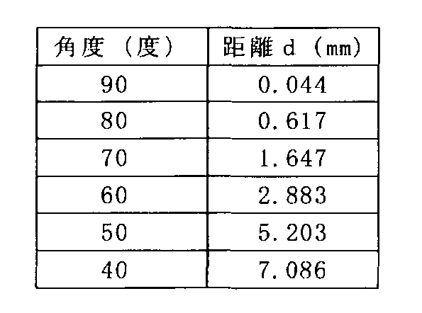
図15に示す近似曲線は2次曲線である。図15に示すように、ダーツDの角度に対する距離dは、距離dを縦軸、ダーツDの角度を横軸として、2次曲線で近似することができる。距離dは使用するダーツDの先端部の材質の太さや剛性に依存するため、使用する環境に合わせ、2次曲線(近似式)を求める。そして、この求めた2次曲線を用いて、ダーツDの位置を決定することができる。
以上、第2実施形態によれば、再帰性反射材24が、ダーツボード12から板厚方向に並んで離間配置された2つの反射材24A、24Bを含むので、光源LSから発せられた光から、光軸L1の光と光軸L2の光の2つの光に分離することができる。これら2つの光の明暗を利用して、ダーツDにおいて、盤面20Aからの距離が異なる位置の影を取得することができる。
そして、第2実施形態によれば、CPU41aは、2つの光の明暗に基づき、ダーツボード12に対するダーツDの傾きを算出し、算出した傾きに基づき、ダーツDが刺さった位置を算出するので、傾きを算出しない場合に比べて、ダーツDの位置をより正確に算出することができる。
また、第2実施形態では、CPU41aは、ダーツDの傾きに沿ったダーツDの仮想線I1と、ダーツボード12の盤面20Aとの交点P3の位置に比べてダーツDの後端側の位置P4を、ダーツDが刺さった位置として算出するので、ダーツDの屈曲を考慮した、ダーツDの位置をより正確に算出することができる。
<変形例>
なお、本発明は上記実施形態に限定されるものではない。すなわち、上記実施形態に、当業者が適宜設計変更を加えたものも、本発明の特徴を備えている限り、本発明の範囲に包含される。また、前述した実施形態が備える各要素は、技術的に可能な限りにおいて組み合わせることができ、これらを組み合わせたものも本発明の特徴を含む限り本発明の範囲に包含される。
なお、本発明は上記実施形態に限定されるものではない。すなわち、上記実施形態に、当業者が適宜設計変更を加えたものも、本発明の特徴を備えている限り、本発明の範囲に包含される。また、前述した実施形態が備える各要素は、技術的に可能な限りにおいて組み合わせることができ、これらを組み合わせたものも本発明の特徴を含む限り本発明の範囲に包含される。
例えば、第1実施形態では、再帰性反射材24を設ける場合を説明したが、この再帰性反射材24を省略してもよい。この場合、例えば図16に示すように、ダーツボード12の周囲に複数の光源LSを並べて配置することで、第1実施形態と同様に、ダーツDの位置を検出してもよい。
また、第2実施形態では、2つの光軸L1、L2を得るために、2つの反射材24A、24Bを設ける場合を説明したが、これらの代わりに、例えば図17に示すように、板厚方向に2段重ねた光源LSを設けてもよい。
また、第2実施形態では、板厚方向に2段の光センサSE1、SE2を設ける場合を説明したが、これらの代わりに、例えば図17に示すように、光軸L1の光と光軸L2の光それぞれを受光可能な幅を有する光センサSE3を設けてもよい。
また、第2実施形態においてCPU41aは、ダーツDの2箇所のピークに基づき、ダーツボード12に対するダーツDの傾きを算出する場合を説明したが、この算出の際、以下の更なる処理を追加してもよい。この更なる処理として、CPU41aは、ダーツボード12Aに新規のダーツDが刺さり、光センサSE1又はSE2が検出した1つの光の明暗に複数のピーク(ダーツDの影)が存在する場合、RAM42bに記憶している、既存のダーツDの過去のピークに基づき、複数のピークの中から既存のダーツの現在のピークを特定し、特定した現在のピーク以外のピークに基づき、ダーツDの傾きを算出してもよい。
上記更なる処理を追加する理由について説明する。図18に示すように、ダーツDが一箇所に集中して刺さった場合、既存のダーツD10と新規に刺さったダーツD11同士が接触する場合がある。このような場合、壁面20Aに刺さった既存のダーツD10の先端位置P10は動かないが、既存のダーツD10の先端部が屈曲することで、既存のダーツD10の後端側位置P11、P12は動いてしまう。このため、光センサSE1が検出した光軸L1の光の明暗には、仮に前回の明暗の差分をとったとしても、新規のダーツD11の位置P13に基づくピークの他に、既存のダーツD10の後端側位置P12に基づくピークが存在するようになる。同様に、光センサSE2が検出した光軸L2の光の明暗には、仮に前回の光の明暗の差分をとったとしても、新規のダーツD11の位置P14に基づくピークの他に、既存のダーツD10の後端側位置P11に基づくピークが存在するようになる。このような状況において、CPU41aが、例えば、位置P13のピークと位置P11のピークの組み合わせ、或いは、位置P12のピークと位置P14のピークの組み合わせに基づいて、新規のダーツD11の位置を算出すると、正しい位置P15とは異なる位置P16、P17が算出されてしまう。
したがって、上記更なる処理を追加し、CPU41aが、既存のダーツD10の過去のピークに基づき、複数のピークの中から既存のダーツD10の位置P11のピーク及び位置P12のピークを特定し、特定したピーク以外のピーク、すなわち位置P13のピーク及び位置P14のピークに基づき、新規のダーツDの傾きを算出することで、正しい位置P15を算出することができる。
したがって、上記更なる処理を追加し、CPU41aが、既存のダーツD10の過去のピークに基づき、複数のピークの中から既存のダーツD10の位置P11のピーク及び位置P12のピークを特定し、特定したピーク以外のピーク、すなわち位置P13のピーク及び位置P14のピークに基づき、新規のダーツDの傾きを算出することで、正しい位置P15を算出することができる。
10…ダーツゲーム装置、12,12A…ダーツボード、24…再帰性反射材、LS…光源、S,S1~S10,SE1,SE2,SE3…光センサ
Claims (8)
- 1人の遊戯者が連続してn本(n=3又は4)のダーツをダーツボードに投げるダーツゲームを提供するダーツゲーム装置であって、
前記ダーツボードの周囲に配置され、前記ダーツボードの盤面に沿って光を発する光源と、
前記ダーツボードの周囲において前記ダーツボードからそれぞれ板厚方向に略同じ高さに配置され、前記光源から発せられた光の明暗を検出する複数の光センサと、
前記複数の光センサにより検出された光の明暗に基づき、前記ダーツボードにおいて前記ダーツが刺さった位置を算出する処理装置と
を備え、
前記光センサの数がn×2個である、
ダーツゲーム装置。 - 前記ダーツボードの周囲に配置された再帰性反射材、
を更に備える請求項1に記載のダーツゲーム装置。 - 前記再帰性反射材は、前記ダーツボードから板厚方向に並んで離間配置された二つの反射材を含む、
請求項2に記載のダーツゲーム装置。 - 前記処理装置は、前記ダーツボードに前記ダーツが刺さった場合に前記光センサが検出した光の明暗を記憶し、前記ダーツボードに次のダーツが刺さった場合に前記光センサが検出した光の明暗と、記憶した光の明暗との差分を算出し、前記差分に基づき、前記次のダーツが刺さった位置を算出する、
請求項1乃至3の何れか1項に記載のダーツゲーム装置。 - 前記光センサは、前記ダーツボードから板厚方向に異なる高さで通過する複数の光軸それぞれの光の明暗を検出し、
前記処理装置は、前記複数の光軸それぞれの光の明暗に基づき、前記ダーツボードに対する前記ダーツの傾きを算出し、算出した傾きに基づき、前記ダーツが刺さった位置を算出する、
請求項1乃至4の何れか1項に記載のダーツゲーム装置。 - 前記処理装置は、前記ダーツボードに既存のダーツに続いて新規のダーツが刺さり、前記光センサが検出した1つの光軸の光の明暗において前記ダーツに基づいた複数の光の明暗が存在する場合、前記既存のダーツの過去の光の明暗に基づき、前記複数の光の明暗の中から前記既存のダーツの現在の光の明暗を特定し、特定した現在の光の明暗以外の光の明暗に基づき、前記新規のダーツの傾きを算出する、
請求項5に記載のダーツゲーム装置。 - 前記処理装置は、前記傾きに基づく仮想線と前記ダーツボードとの交点の位置に比べて、前記ダーツの後端側の位置を、前記ダーツが刺さった位置として算出する、
請求項5又は6に記載のダーツゲーム装置。 - 前記処理装置は、前記ダーツの特性に基づいて、前記ダーツが刺さった位置を算出する、
請求項1乃至7の何れか1項に記載のダーツゲーム装置。
Priority Applications (5)
| Application Number | Priority Date | Filing Date | Title |
|---|---|---|---|
| EP18842106.9A EP3663700B1 (en) | 2017-07-31 | 2018-07-30 | Darts game device |
| CN201880048455.7A CN110959098B (zh) | 2017-07-31 | 2018-07-30 | 飞镖游戏装置 |
| SG11202000355SA SG11202000355SA (en) | 2017-07-31 | 2018-07-30 | Dart game apparatus |
| US16/631,108 US11112220B2 (en) | 2017-07-31 | 2018-07-30 | Dart game apparatus |
| PL18842106.9T PL3663700T3 (pl) | 2017-07-31 | 2018-07-30 | Urządzenie do gry w rzutki |
Applications Claiming Priority (2)
| Application Number | Priority Date | Filing Date | Title |
|---|---|---|---|
| JP2017-148514 | 2017-07-31 | ||
| JP2017148514A JP6966677B2 (ja) | 2017-07-31 | 2017-07-31 | ダーツゲーム装置 |
Publications (1)
| Publication Number | Publication Date |
|---|---|
| WO2019026856A1 true WO2019026856A1 (ja) | 2019-02-07 |
Family
ID=65233847
Family Applications (1)
| Application Number | Title | Priority Date | Filing Date |
|---|---|---|---|
| PCT/JP2018/028503 Ceased WO2019026856A1 (ja) | 2017-07-31 | 2018-07-30 | ダーツゲーム装置 |
Country Status (8)
| Country | Link |
|---|---|
| US (1) | US11112220B2 (ja) |
| EP (1) | EP3663700B1 (ja) |
| JP (1) | JP6966677B2 (ja) |
| CN (1) | CN110959098B (ja) |
| PL (1) | PL3663700T3 (ja) |
| SG (1) | SG11202000355SA (ja) |
| TW (1) | TWI784033B (ja) |
| WO (1) | WO2019026856A1 (ja) |
Cited By (2)
| Publication number | Priority date | Publication date | Assignee | Title |
|---|---|---|---|---|
| WO2021021123A1 (en) * | 2019-07-30 | 2021-02-04 | Archery Intelligence, LLC | Archery tuning system |
| CN114935282A (zh) * | 2022-06-10 | 2022-08-23 | 河海大学 | 一种用于飞镖训练的语音报分系统 |
Families Citing this family (6)
| Publication number | Priority date | Publication date | Assignee | Title |
|---|---|---|---|---|
| KR102548105B1 (ko) * | 2022-08-16 | 2023-06-27 | 주식회사 피닉스다트 | 다트핀 히트 위치 식별 방법, 컴퓨터 프로그램, 및 장치 |
| USD1006880S1 (en) * | 2023-03-29 | 2023-12-05 | Guochao Chen | Inflatable dart board |
| USD1001894S1 (en) * | 2023-03-29 | 2023-10-17 | Guochao Chen | Inflatable dart board |
| USD1139641S1 (en) * | 2024-01-17 | 2026-08-04 | Brett Jackowski | Golf dart game |
| USD1057829S1 (en) * | 2024-05-31 | 2025-01-14 | Bo Huang | Inflatable game target |
| USD1118753S1 (en) * | 2025-05-06 | 2026-03-17 | Brett Jackowski | Inflatable bullseye |
Citations (5)
| Publication number | Priority date | Publication date | Assignee | Title |
|---|---|---|---|---|
| US4789932A (en) * | 1984-09-21 | 1988-12-06 | Austin T. Musselman | Apparatus and method for automatically scoring a dart game |
| JP2001509251A (ja) | 1997-01-20 | 2001-07-10 | ドモテック システムテヒニーク ゲゼルシャフト ミット ベシュレンクテル ハフツング | 標的上の矢の衝突点の検出のための装置 |
| WO2006070875A1 (ja) * | 2004-12-31 | 2006-07-06 | Sega Corporation | ダーツゲーム装置 |
| KR20100034643A (ko) * | 2008-09-24 | 2010-04-01 | 주식회사 지닌 | 발광 소자 및 수광 소자를 이용한 다트 게임의 스코어링 장치 및 방법 |
| CN106595396A (zh) * | 2016-12-15 | 2017-04-26 | 深圳分汇科技有限公司 | 一种红外电子计分飞镖靶 |
Family Cites Families (7)
| Publication number | Priority date | Publication date | Assignee | Title |
|---|---|---|---|---|
| US6717684B1 (en) * | 2000-06-09 | 2004-04-06 | Dynetics, Inc. | Target scoring system |
| KR101517348B1 (ko) * | 2013-01-07 | 2015-05-04 | 주식회사 홍인터내셔날 | 다트 게임을 촬영하기 위한 촬영 장치를 포함하는 다트 게임 장치 |
| WO2016203194A1 (en) * | 2015-06-18 | 2016-12-22 | Flight Path Ip Limited | Automatic dartboard scoring system |
| KR101627264B1 (ko) * | 2015-08-10 | 2016-06-03 | 주식회사 홍인터내셔날 | 복수의 카메라를 구비한 다트 게임 장치 및 컴퓨터-판독가능 매체에 저장된 컴퓨터 프로그램 |
| CN105180721B (zh) * | 2015-08-11 | 2017-10-31 | 中国船舶重工集团公司第七0九研究所 | 自动报靶及测速装置及其定位测速方法 |
| CN205699365U (zh) * | 2016-04-14 | 2016-11-23 | 薛梓瑗 | 飞镖游戏设备 |
| CN106323097A (zh) * | 2016-08-25 | 2017-01-11 | 中国人民解放军总参谋部第六十研究所 | 一种共面三边感光的光电靶装置 |
-
2017
- 2017-07-31 JP JP2017148514A patent/JP6966677B2/ja active Active
-
2018
- 2018-07-30 CN CN201880048455.7A patent/CN110959098B/zh active Active
- 2018-07-30 WO PCT/JP2018/028503 patent/WO2019026856A1/ja not_active Ceased
- 2018-07-30 US US16/631,108 patent/US11112220B2/en active Active
- 2018-07-30 SG SG11202000355SA patent/SG11202000355SA/en unknown
- 2018-07-30 PL PL18842106.9T patent/PL3663700T3/pl unknown
- 2018-07-30 EP EP18842106.9A patent/EP3663700B1/en active Active
- 2018-07-31 TW TW107126482A patent/TWI784033B/zh active
Patent Citations (6)
| Publication number | Priority date | Publication date | Assignee | Title |
|---|---|---|---|---|
| US4789932A (en) * | 1984-09-21 | 1988-12-06 | Austin T. Musselman | Apparatus and method for automatically scoring a dart game |
| JP2001509251A (ja) | 1997-01-20 | 2001-07-10 | ドモテック システムテヒニーク ゲゼルシャフト ミット ベシュレンクテル ハフツング | 標的上の矢の衝突点の検出のための装置 |
| WO2006070875A1 (ja) * | 2004-12-31 | 2006-07-06 | Sega Corporation | ダーツゲーム装置 |
| JP4682986B2 (ja) | 2004-12-31 | 2011-05-11 | 株式会社セガ | ダーツゲーム装置 |
| KR20100034643A (ko) * | 2008-09-24 | 2010-04-01 | 주식회사 지닌 | 발광 소자 및 수광 소자를 이용한 다트 게임의 스코어링 장치 및 방법 |
| CN106595396A (zh) * | 2016-12-15 | 2017-04-26 | 深圳分汇科技有限公司 | 一种红外电子计分飞镖靶 |
Non-Patent Citations (1)
| Title |
|---|
| See also references of EP3663700A4 |
Cited By (3)
| Publication number | Priority date | Publication date | Assignee | Title |
|---|---|---|---|---|
| WO2021021123A1 (en) * | 2019-07-30 | 2021-02-04 | Archery Intelligence, LLC | Archery tuning system |
| US12693099B2 (en) | 2019-07-30 | 2026-07-28 | Archery Intelligence, LLC | Archery tuning system |
| CN114935282A (zh) * | 2022-06-10 | 2022-08-23 | 河海大学 | 一种用于飞镖训练的语音报分系统 |
Also Published As
| Publication number | Publication date |
|---|---|
| TW201919742A (zh) | 2019-06-01 |
| EP3663700A1 (en) | 2020-06-10 |
| CN110959098B (zh) | 2022-07-15 |
| US20200132419A1 (en) | 2020-04-30 |
| JP2019027703A (ja) | 2019-02-21 |
| JP6966677B2 (ja) | 2021-11-17 |
| EP3663700B1 (en) | 2026-02-25 |
| PL3663700T3 (pl) | 2026-05-11 |
| TWI784033B (zh) | 2022-11-21 |
| US11112220B2 (en) | 2021-09-07 |
| CN110959098A (zh) | 2020-04-03 |
| EP3663700A4 (en) | 2021-04-28 |
| SG11202000355SA (en) | 2020-02-27 |
| EP3663700C0 (en) | 2026-02-25 |
Similar Documents
| Publication | Publication Date | Title |
|---|---|---|
| JP6966677B2 (ja) | ダーツゲーム装置 | |
| JP5016049B2 (ja) | 対象の方向性の決定 | |
| US5649706A (en) | Simulator and practice method | |
| KR101475120B1 (ko) | 빔프로젝트를 구비한 다트 게임 장치 | |
| JP4682986B2 (ja) | ダーツゲーム装置 | |
| JP2013521077A (ja) | ゴルフクラブのシャフトのしなりを測定する装置及び方法、並びに該装置を組み込んだゴルフシュミレーションシステム | |
| KR20140062611A (ko) | 디스플레이를 구비한 다트 게임 장치 | |
| CN110945313B (zh) | 飞镖游戏装置以及存储介质 | |
| US6663391B1 (en) | Spotlighted position detection system and simulator | |
| JP5342855B2 (ja) | 射撃訓練用模擬対抗装置 | |
| JP2017120175A (ja) | 標的システム、およびプログラム | |
| HK40017103A (en) | Darts game device | |
| HK40017103B (en) | Darts game device | |
| US6964607B2 (en) | Game system and game method | |
| JPH0838741A (ja) | 射撃ゲーム装置 | |
| JP5342854B2 (ja) | 射撃訓練用模擬対抗装置 | |
| EP3564617B1 (en) | Optical sensing target | |
| HK40016564A (en) | Darts game device and storage medium | |
| TWI754769B (zh) | 飛鏢遊戲裝置及方法 | |
| JP6904834B2 (ja) | ダーツゲーム装置、ダーツ速度表示方法及びプログラム | |
| JP2011004919A (ja) | メダル投入装置およびメダルゲーム装置 | |
| JPWO2019171830A1 (ja) | 情報処理装置、情報処理方法、およびプログラム | |
| JPH0429648Y2 (ja) | ||
| JP2025141638A (ja) | 射撃ゲームシステムおよび娯楽施設 | |
| KR101068799B1 (ko) | 스크린 사격 장치에 이용되는 제어 장치 및 그 장치의 구동 방법 |
Legal Events
| Date | Code | Title | Description |
|---|---|---|---|
| 121 | Ep: the epo has been informed by wipo that ep was designated in this application |
Ref document number: 18842106 Country of ref document: EP Kind code of ref document: A1 |
|
| NENP | Non-entry into the national phase |
Ref country code: DE |
|
| ENP | Entry into the national phase |
Ref document number: 2018842106 Country of ref document: EP Effective date: 20200302 |
|
| WWG | Wipo information: grant in national office |
Ref document number: 2018842106 Country of ref document: EP |