WO2019029338A1 - 一种信息传输方法及装置 - Google Patents
一种信息传输方法及装置 Download PDFInfo
- Publication number
- WO2019029338A1 WO2019029338A1 PCT/CN2018/096433 CN2018096433W WO2019029338A1 WO 2019029338 A1 WO2019029338 A1 WO 2019029338A1 CN 2018096433 W CN2018096433 W CN 2018096433W WO 2019029338 A1 WO2019029338 A1 WO 2019029338A1
- Authority
- WO
- WIPO (PCT)
- Prior art keywords
- ptrs
- frequency domain
- bandwidth
- domain density
- available
- Prior art date
- Legal status (The legal status is an assumption and is not a legal conclusion. Google has not performed a legal analysis and makes no representation as to the accuracy of the status listed.)
- Ceased
Links
Images


Classifications
-
- H—ELECTRICITY
- H04—ELECTRIC COMMUNICATION TECHNIQUE
- H04L—TRANSMISSION OF DIGITAL INFORMATION, e.g. TELEGRAPHIC COMMUNICATION
- H04L5/00—Arrangements affording multiple use of the transmission path
- H04L5/0001—Arrangements for dividing the transmission path
- H04L5/0003—Two-dimensional division
- H04L5/0005—Time-frequency
- H04L5/0007—Time-frequency the frequencies being orthogonal, e.g. OFDM(A) or DMT
-
- H—ELECTRICITY
- H04—ELECTRIC COMMUNICATION TECHNIQUE
- H04W—WIRELESS COMMUNICATION NETWORKS
- H04W28/00—Network traffic management; Network resource management
- H04W28/02—Traffic management, e.g. flow control or congestion control
- H04W28/0252—Traffic management, e.g. flow control or congestion control per individual bearer or channel
- H04W28/0263—Traffic management, e.g. flow control or congestion control per individual bearer or channel involving mapping traffic to individual bearers or channels, e.g. traffic flow template [TFT]
-
- H—ELECTRICITY
- H04—ELECTRIC COMMUNICATION TECHNIQUE
- H04L—TRANSMISSION OF DIGITAL INFORMATION, e.g. TELEGRAPHIC COMMUNICATION
- H04L27/00—Modulated-carrier systems
- H04L27/26—Systems using multi-frequency codes
- H04L27/2601—Multicarrier modulation systems
- H04L27/2602—Signal structure
- H04L27/261—Details of reference signals
- H04L27/2613—Structure of the reference signals
-
- H—ELECTRICITY
- H04—ELECTRIC COMMUNICATION TECHNIQUE
- H04L—TRANSMISSION OF DIGITAL INFORMATION, e.g. TELEGRAPHIC COMMUNICATION
- H04L5/00—Arrangements affording multiple use of the transmission path
- H04L5/003—Arrangements for allocating sub-channels of the transmission path
- H04L5/0048—Allocation of pilot signals, i.e. of signals known to the receiver
- H04L5/0051—Allocation of pilot signals, i.e. of signals known to the receiver of dedicated pilots, i.e. pilots destined for a single user or terminal
-
- H—ELECTRICITY
- H04—ELECTRIC COMMUNICATION TECHNIQUE
- H04L—TRANSMISSION OF DIGITAL INFORMATION, e.g. TELEGRAPHIC COMMUNICATION
- H04L5/00—Arrangements affording multiple use of the transmission path
- H04L5/003—Arrangements for allocating sub-channels of the transmission path
- H04L5/0058—Allocation criteria
- H04L5/0064—Rate requirement of the data, e.g. scalable bandwidth, data priority
-
- H—ELECTRICITY
- H04—ELECTRIC COMMUNICATION TECHNIQUE
- H04W—WIRELESS COMMUNICATION NETWORKS
- H04W72/00—Local resource management
- H04W72/04—Wireless resource allocation
- H04W72/044—Wireless resource allocation based on the type of the allocated resource
-
- H—ELECTRICITY
- H04—ELECTRIC COMMUNICATION TECHNIQUE
- H04W—WIRELESS COMMUNICATION NETWORKS
- H04W72/00—Local resource management
- H04W72/04—Wireless resource allocation
- H04W72/044—Wireless resource allocation based on the type of the allocated resource
- H04W72/0446—Resources in time domain, e.g. slots or frames
-
- H—ELECTRICITY
- H04—ELECTRIC COMMUNICATION TECHNIQUE
- H04W—WIRELESS COMMUNICATION NETWORKS
- H04W72/00—Local resource management
- H04W72/04—Wireless resource allocation
- H04W72/044—Wireless resource allocation based on the type of the allocated resource
- H04W72/0453—Resources in frequency domain, e.g. a carrier in FDMA
-
- H—ELECTRICITY
- H04—ELECTRIC COMMUNICATION TECHNIQUE
- H04W—WIRELESS COMMUNICATION NETWORKS
- H04W72/00—Local resource management
- H04W72/30—Resource management for broadcast services
-
- H—ELECTRICITY
- H04—ELECTRIC COMMUNICATION TECHNIQUE
- H04B—TRANSMISSION
- H04B2201/00—Indexing scheme relating to details of transmission systems not covered by a single group of H04B3/00 - H04B13/00
- H04B2201/69—Orthogonal indexing scheme relating to spread spectrum techniques in general
- H04B2201/7163—Orthogonal indexing scheme relating to impulse radio
- H04B2201/71636—Transmitted reference
-
- H—ELECTRICITY
- H04—ELECTRIC COMMUNICATION TECHNIQUE
- H04L—TRANSMISSION OF DIGITAL INFORMATION, e.g. TELEGRAPHIC COMMUNICATION
- H04L27/00—Modulated-carrier systems
- H04L27/26—Systems using multi-frequency codes
- H04L27/2601—Multicarrier modulation systems
- H04L27/2647—Arrangements specific to the receiver only
- H04L27/2655—Synchronisation arrangements
- H04L27/2657—Carrier synchronisation
-
- H—ELECTRICITY
- H04—ELECTRIC COMMUNICATION TECHNIQUE
- H04L—TRANSMISSION OF DIGITAL INFORMATION, e.g. TELEGRAPHIC COMMUNICATION
- H04L27/00—Modulated-carrier systems
- H04L27/26—Systems using multi-frequency codes
- H04L27/2601—Multicarrier modulation systems
- H04L27/2647—Arrangements specific to the receiver only
- H04L27/2655—Synchronisation arrangements
- H04L27/2668—Details of algorithms
- H04L27/2673—Details of algorithms characterised by synchronisation parameters
- H04L27/2675—Pilot or known symbols
-
- H—ELECTRICITY
- H04—ELECTRIC COMMUNICATION TECHNIQUE
- H04W—WIRELESS COMMUNICATION NETWORKS
- H04W28/00—Network traffic management; Network resource management
- H04W28/02—Traffic management, e.g. flow control or congestion control
- H04W28/0205—Traffic management, e.g. flow control or congestion control at the air interface
Definitions
- the present application relates to the field of communications technologies, and more particularly to the transmission of signals in a wireless communication system.
- the operating band of 6GHz or more next generation radio communication network can provide ultra-high speed data communication service.
- the frequency bands available for the next generation wireless communication network include frequency bands at 28 GHz, 39 GHz, 60 GHz, 73 GHz, and the like.
- High-frequency communication systems above 6 GHz have significant features such as large bandwidth and highly integrated antenna arrays, making it easy to achieve higher throughput.
- high-frequency communication systems will suffer from more severe medium-frequency distortion, especially phase noise (PHN) or phase shift.
- PPN phase noise
- Doppler effect and carrier frequency offset are also increase as the location of the frequency band becomes higher.
- a common feature of phase noise, Doppler effect and CFO is the introduction of phase error or phase offset for data reception in high frequency communication systems, resulting in reduced or even inoperable performance of high frequency communication systems.
- PTRS phase tracking reference signal
- CPE common phase error
- One prior art is to set the association between the PTRS frequency domain density and the scheduling bandwidth.
- the relationship between the PTRS frequency domain density and the scheduling bandwidth is as shown in Table 1:
- the wider the scheduling bandwidth the smaller the PTRS frequency domain density, that is, FD 1 >FD 2 >...>FD 5 .
- the scheduling bandwidth is 6 RB corresponding to 6 PTRSs, 8 RBs correspond to 4 PTRSs, 30 RBs correspond to 15 PTRSs, and 32 RBs correspond to 8 PTRSs, that is, near the threshold, the number of PTRSs is reduced due to the increase of scheduling bandwidth, and CPE cannot be guaranteed. Estimated accuracy. Because of the hopping, the scheduling bandwidth is reduced, and the number of PTRS is increased, which will reduce the spectrum efficiency.
- Another prior art is to set the relationship between the number of PTRS frequency domains and the scheduling bandwidth.
- the relationship between the number of PTRS frequency domains and the scheduling bandwidth is as shown in Table 2:
- the number of PTRS frequency domains corresponding to each interval is fixed, which ensures that the number of PTRS remains unchanged or increases as the scheduling bandwidth increases.
- P denotes the number of scheduled RBs, that is, N RB ;
- L denotes the number of PTRSs;
- k is an offset value, which can be set to 0 or 1.
- RSs reference signals
- the application provides an information transmission method and apparatus for reasonably configuring a PTRS.
- an information transmission scheme determines a time domain density of the mapped phase tracking reference signal PTRS; determines a frequency domain density of the mapped PTRS; and maps the PTRS to the orthogonal frequency division multiplexing according to the time domain density, the frequency domain density, and/or the frequency domain offset And transmitting a signal including an OFDM symbol to which the PTRS is mapped.
- the frequency domain density of the PTRS can be determined based on the available bandwidth, and then the PTRS mapping is performed. Since the PTRS is mapped based on the available bandwidth instead of the scheduled bandwidth, the PTRS is not mapped on the conflicted bandwidth, and the PRTS can be effectively avoided. Other signal conflicts.
- the frequency domain density of the PTRS may be determined according to the index information of the scheduling or available resource block RB or the number of scheduling or available RBs. In this design, it is avoided that the number of PTRSs hops near the threshold of the scheduling bandwidth, taking into account the accuracy and spectral efficiency of the common phase error estimation, and uniformly mapping the PTRS within the scheduling or available bandwidth, thereby The PTRS is configured reasonably.
- the receiving end device receives one or more orthogonal frequency division multiplexing OFDM symbols; and determines a phase tracking reference signal PTRS mapped on the one or more OFDM symbols. Determining the PTRS includes determining a time domain density of the phase tracking reference signal PTRS; and determining a frequency domain density of the phase tracking reference signal PTRS based on the available bandwidth, or determining a frequency domain density of the phase tracking reference signal PTRS based on the scheduling or available resource block RB.
- the receiving end device can accurately and efficiently acquire the received signal on the PTRS based on the time domain density and the frequency domain density of the PTRS, thereby improving the receiving efficiency of the PTRS signal.
- the determining the time domain density of the mapped PTRS comprises: determining a time domain density of the mapped PTRS according to the modulation and coding mode MCS.
- the time domain density of the PTRS is determined, i.e., which symbols are mapped on which symbols are mapped.
- the determining, according to the index information of the scheduling or the available RB, or the number of the scheduled or available RBs, determining the frequency domain density of the mapped PTRS including: dividing the scheduled or available RB into at least one RB index interval.
- Each RB index interval corresponds to a frequency domain density of one PTRS.
- the scheduling or available RB is divided into one or more RB index intervals, and each RB index interval may correspond to a frequency domain density of different PTRSs, so that the PTRS may be evenly distributed in the frequency domain.
- each RB index interval corresponds to one of the frequency domain offsets, where the frequency domain offset is a frequency domain of a PTRS corresponding to each RB index interval.
- the balance of density is obtained by the remainder operation, and the PTRS is mapped according to the frequency domain offset in each RB index interval, so that the PTRS can be evenly distributed in the frequency domain.
- each RB index interval corresponds to one of the frequency domain offsets, and the frequency domain offset corresponding to each RB index interval is a predetermined value; or at least one frequency domain offset Forming a correspondence table with the at least one RB index interval.
- the index information of the scheduled or available RB is a sequence number sorted by the scheduled virtual RB number, or the index information of the scheduled or available RB is sorted by the scheduled physical RB number. serial number.
- the index of the RB is a relative RB number such that the index of the scheduled or available RB is an ordered number.
- an information transmission scheme where a transmitting end device uniformly configures a PTRS mapping PTRS on an OFDM symbol, and a receiving end device receives an orthogonal frequency division multiplexing OFDM symbol that maps a phase tracking reference signal PTRS; Acquiring a received signal on the PTRS.
- the PTRS is mapped to an OFDM symbol according to a time domain density, a frequency domain density, and/or a frequency domain offset, where the frequency domain density is based on scheduling information of an available or available resource block RB or a scheduled or available RB. The number is determined.
- the transmitting end device is uniformly configured with the PTRS, the receiving end device can accurately and efficiently acquire the received signal on the PTRS, thereby improving the receiving efficiency of the PTRS signal.
- the method further includes: performing common phase error estimation according to the received signal on the PTRS.
- the common phase error estimation can be accurately performed using the received signal of the PTRS.
- the available bandwidth is a part of the scheduling bandwidth that does not include (exclude) the preempted bandwidth; or the available bandwidth is a part of the scheduling bandwidth that does not include (exclude) the reserved bandwidth; or The available bandwidth is a portion of the scheduled bandwidth that does not include (exclude) the preempted bandwidth and the reserved bandwidth.
- the available bandwidth can be calculated separately on those symbols that map the PTRS. For example, if the time domain density of PTRS is 1/2, then one possible way is that PTRS is mapped on the first, third, fifth, seventh, etc. symbols, respectively, and the first, third, fifth, and fifth are calculated. The available bandwidth on 7... symbols.
- the downlink signal includes one or more of the following: a synchronization block SS block, a physical downlink control channel PDCCH, an enhanced physical downlink control channel EPDCCH or a physical broadcast channel PBCH, or a primary synchronization signal PSS, The secondary synchronization signal SSS, or the demodulation reference signal DMRS, and the channel state information reference signal CSI-RS.
- the uplink signal is one or more of the following: a physical uplink control channel PUCCH, a demodulation reference signal DMRS, and a sounding reference signal SRS.
- a table is pre-configured or pre-stored, the table recording mapping relationship information of available bandwidth and frequency domain density or number of frequency domain PTRS.
- the sender device and/or the sink device may save a correspondence list.
- the list includes at least one RB index interval and a frequency domain density of at least one PTRS, wherein the RB index interval has a one-to-one correspondence with a density of the PTRS frequency domain; or
- the list includes a number interval of at least one RB and a frequency domain density of at least one PTRS, wherein the number of intervals of the RB has a one-to-one correspondence with a frequency domain density of the PRTS; or
- the list includes at least one RB index interval, a frequency domain density of at least one PTRS, and at least one frequency domain offset, wherein the RB index interval, the frequency domain density of the PRTS, and the frequency domain offset have one a correspondence; or
- the list includes a number interval of at least one RB, a frequency domain density of at least one PTRS, at least one frequency domain offset, wherein the number of intervals of the RB, a frequency domain density of the PRTS, and the frequency domain offset
- the shift has a one-to-one correspondence.
- the frequency domain density of the PTRS is 0 or the number of frequency domain PTRSs is 0.
- the sending end device may send one or more of the following information to the terminal device: sending information indicating the current MCS index information; information indicating the scheduling bandwidth, and sending information indicating the preempted bandwidth, for transmitting Information indicating the reserved bandwidth to the terminal device.
- a communication scheme where a source device determines a time domain density of a mapped phase tracking reference signal PTRS; determines a number L of mapped PTRSs in a frequency domain; and determines N RB resource blocks RB according to the following formula:
- the frequency domain RB number i of the mapped L PTRSs is: Where k 1 is an offset and k 1 is an integer; the PTRS is mapped onto the OFDM symbol according to the time domain density and the frequency domain RB number of the PTRS; and the OFDM symbol mapped with the PTRS is transmitted.
- the receiving end device receives the orthogonal frequency division multiplexing OFDM symbol to which the phase tracking reference signal PTRS is mapped; and acquires the received signal on the PTRS.
- the configuration of the PTRS takes into account the accuracy and spectral efficiency of the common phase error estimation, and can uniformly map the PTRS within the scheduling or available bandwidth, thereby reasonably configuring the PTRS.
- the receiving end device can accurately and efficiently acquire the receiving signal on the PTRS, thereby improving the receiving efficiency of the PTRS signal.
- the RB number is a sequence number of the scheduled virtual RB number, or the RB number is a sequence number of the scheduled physical RB number.
- the index of the RB is a relative RB number such that the index of the scheduled or available RB is an ordered number.
- the frequency domain resource units may be determined number Index RE L RE on a PTRS N RB resource blocks according to the following formula:
- the I DMRS is a frequency domain interval of the demodulation reference signal DMRS;
- k 2 is an offset of the RE,
- the PTRS is mapped from the RE level and the mapped location of the PTRS is related to the DMRS location of its associated DMRS port.
- a further aspect of the present application further provides a communication device, which can be used as a transmitting device or a receiving device to implement any of the foregoing communication solutions.
- the communication device may be a chip (such as a baseband chip, or a communication chip, etc.) or a device (such as a network device, a base station, a baseband board, a terminal device, etc.).
- the above method can be implemented by software, hardware, or by executing corresponding software by hardware.
- the structure of the communication device includes a processor and a memory; the processor is configured to support the device to perform a corresponding function in the foregoing communication method.
- the memory is for coupling with a processor that holds the necessary programs (instructions) and/or data for the device.
- the communication device may further comprise a communication interface for supporting communication between the device and other network elements.
- the communication device may include a processing unit and a transceiver unit.
- the transceiver unit is configured to implement a sending/receiving function, and the processing unit is configured to implement the foregoing processing functions.
- a processing unit is configured to determine a time domain density of the mapped phase tracking reference signal PTRS; the processing unit is further configured to determine a frequency domain density of the PTRS.
- the communication device may further include a storage unit for implementing the above save/store function, for example, storing a correspondence list, or other necessary programs (instructions) and data.
- the processing unit may be implemented by one or more processors, which may be implemented by one or more processors.
- the transceiver unit may be a transceiver circuit (input/output circuit) or a communication interface, or a transceiver (transceiver).
- the transceiver unit may be an input/output circuit or a communication interface.
- the transceiver unit may be a transceiver (which may also be referred to as a transceiver).
- the processing unit may be configured to determine a time domain density of the mapped PTRS according to the modulation and coding mode MCS.
- the processing unit may be configured to divide the scheduled or available RB into at least one RB index interval, where each RB index interval corresponds to a frequency domain density of one PTRS.
- each RB index interval corresponds to one of the frequency domain offsets, where the frequency domain offset is a frequency offset of a PTRS corresponding to each RB index interval.
- the surplus is a frequency offset of a PTRS corresponding to each RB index interval.
- each RB index interval corresponds to one of the frequency domain offsets, and a frequency domain offset corresponding to each RB index interval is a predetermined value; or at least one frequency domain offset and The at least one RB index interval constitutes a correspondence table.
- the index information of the scheduled or available RB is a sequence number sorted by the scheduled virtual RB number, or the sequence information of the scheduled or available RB is sorted by the scheduled physical RB number. number.
- the processing unit is further configured to perform common phase error estimation according to the received signal on the PTRS.
- the processing unit is configured to determine the number L of mapped PTRSs in the frequency domain.
- the processing unit is configured to determine a frequency domain resource unit RE number Index RE of the L PTRSs.
- Yet another aspect of the present application provides a wireless communication system including the above-described transmitting device and the above receiving device.
- Yet another aspect of the present application provides a computer readable storage medium having stored therein instructions that, when executed on a computer, cause the computer to perform the methods described in the various aspects above.
- Yet another aspect of the present application provides a computer program product comprising instructions which, when run on a computer, cause the computer to perform the method of the above aspects.
- FIG. 1 is a schematic diagram of a plurality of scheduling bandwidths for mapping a fixed number of PTRSs in the prior art
- FIG. 2 is a schematic diagram of a communication system according to an embodiment of the present invention.
- 3A is a schematic diagram of an interaction process of an information transmission method according to an embodiment of the present invention.
- FIG. 3B is a schematic diagram of an interaction process of another information transmission method according to an embodiment of the present disclosure.
- Figure 4 is a view of several time domain densities of an exemplary PTRS
- FIG. 5 is a schematic diagram of frequency domain mapping of an exemplary PTRS
- 6A is a schematic diagram of an available bandwidth of an example
- 6B is a schematic diagram of another available bandwidth of the example.
- FIG. 7A is a schematic diagram of mapping a PTRS according to an embodiment of the present invention.
- FIG. 7B is a schematic diagram of another mapping PTRS according to an embodiment of the present invention.
- 8A is a schematic diagram of a relationship between a relative resource block number and a VRB/PRB;
- 8B is a schematic diagram showing another relationship between a relative resource block number and a VRB/PRB;
- FIG. 9 is a schematic diagram of interval partitioning and frequency domain mapping of an exemplary scheduling or available RB
- FIG. 10 is a schematic diagram of resource allocation according to an embodiment of the present invention.
- FIG. 11 is a schematic flowchart of interaction of another communication method according to an embodiment of the present disclosure.
- FIG. 12 is a schematic diagram of an RB on which a PTRS is mapped
- FIG. 13 is a schematic block diagram of a terminal device according to an embodiment of the present invention.
- FIG. 14 is a schematic block diagram of a network device according to an embodiment of the present invention.
- FIG. 2 shows a schematic diagram of a communication system.
- the system can be widely used to provide various types of communication such as voice, data, and the like.
- the communication system can be a plurality of wireless communication devices, for example, can include at least one terminal device 200 in communication with a wireless access network.
- the radio access network is connected to a core network.
- the wireless access network includes at least one network device 100 (only one is shown in FIG. 1) in communication with the terminal device 200.
- the network device 100 may be any device having a wireless transceiving function.
- a base station eg, a base station NodeB, an evolved base station eNodeB, a base station in a fifth generation (5G) communication system, a base station or network device in a future communication system, an access node in a WiFi system , wireless relay node, wireless backhaul node, etc.
- the network device 100 may also be a wireless controller in a cloud radio access network (CRAN) scenario.
- the network device 100 may also be a network device in a 5G network or a network device in a future evolved network; it may also be a wearable device or an in-vehicle device or the like.
- the network device 100 may also be a small station, a transmission reference point (TRP) or the like. Of course, no application is not limited to this.
- the terminal device 200 is a device having a wireless transceiving function. It can be deployed on land, indoors or outdoors, hand-held, worn or on-board; it can also be deployed on the water (such as ships); it can also be deployed in the air (such as airplanes, balloons, satellites, etc.).
- the terminal device may be a mobile phone, a tablet (Pad), a computer with wireless transceiver function, a virtual reality (VR) terminal device, an augmented reality (AR) terminal device, and industrial control ( Wireless terminal in industrial control, wireless terminal in self driving, wireless terminal in remote medical, wireless terminal in smart grid, transportation safety A wireless terminal, a wireless terminal in a smart city, a wireless terminal in a smart home, and the like.
- a terminal device may also be referred to as a user equipment (UE), an access terminal device, a UE unit, a UE station, a mobile station, a mobile station, a remote station, a remote terminal device, a mobile device, a UE terminal device, a terminal device, Wireless communication device, UE proxy or UE device, and the like.
- UE user equipment
- system and “network” in the embodiments of the present invention may be used interchangeably.
- Multiple means two or more, and in view of this, "a plurality” may also be understood as “at least two” in the embodiment of the present invention.
- the character "/” unless otherwise specified, generally indicates that the contextual object is an "or" relationship.
- the embodiment of the invention provides a communication method and device, which can be used for uplink transmission or downlink transmission.
- the transmitting device may be a communication device on the network side, and the receiving device is a communication device on the terminal side.
- the transmitting device may be a communication device on the terminal side, and the receiving device is a communication device on the network side.
- the network side communication device includes: a network device or a chip (baseband chip or communication chip, etc.) for the network device.
- the terminal side communication device includes: a terminal device or a chip for the terminal device (such as a baseband chip or a communication chip, etc.).
- the transmitting device and the receiving device may not only be limited to the peer-to-peer network side communication devices and terminals.
- Side communication device For example, the transmitting end device and the receiving end device may both be communication devices on the terminal side that are opposite to each other, or are communication devices on the network side that are mutually opposite.
- the communication device on the network side takes a network device as an example
- the communication device on the terminal side takes a terminal device as an example for description.
- PTRS is mapped into one or more OFDM symbols with a certain time domain and frequency domain density.
- the transmission unit may be a frame, a subframe, a time slot, a mini-slot, an absolute time (such as 5 ms), or the like.
- PTRS is used to track fast changes in the channel. For example, tracking changes in carrier frequency offset (CFO), phase noise (PN), and Doppler shift.
- CFO carrier frequency offset
- PN phase noise
- Doppler shift the PTRS occupies a plurality of subcarriers or Resource Elements (REs) or Resource Blocks (RBs) or Resource Bundles (RBs) in the frequency domain, and can occupy the PTRS for mapping in the time domain.
- REs Resource Elements
- RBs Resource Blocks
- RBs Resource Bundles
- One or more OFDM symbols for example, occupying a portion of the OFDM symbols at a certain interval, or occupying all of the OFDM symbols, or occupying part of the OFDM symbols with other rules, these rules may be specified by the standard, pre-configured or pre-stored in the network device and In the terminal device.
- the OFDM symbol used for mapping the PTRS is all symbols of a Physical Downlink Shared Channel (PDSCH) or a Physical Uplink Shared Channel (PUSCH), or all OFDMs except the mapped DMRS. symbol.
- the control PTRS may also be other control channels, which is not limited herein.
- an embodiment of the present invention provides a method for configuring a reference signal, where the configuration method can be corresponding to downlink transmission or uplink transmission, including:
- the sending end device determines an available bandwidth in the scheduling bandwidth.
- the sending end device determines, according to the available bandwidth, a frequency domain density of the mapped PTRS or a number of frequency domain PTRSs.
- the sender device determines a time domain density of the mapped PTRS.
- the sender device maps the PTRS to one or more OFDM symbols and transmits.
- the receiving device receives the one or more OFDM symbols.
- the receiving end device acquires a time domain density and a frequency domain density or a number of frequency domain PTRSs of the PTRS mapped on the one or more OFDM symbols.
- another embodiment of the present invention provides a method for configuring a reference signal, where the configuration method can correspond to downlink transmission or uplink transmission, including:
- the sender device determines a time domain density of the mapped PTRS.
- the sending end device determines, according to the scheduling information of the scheduling or available RBs, or the number of scheduling or available RBs, the frequency domain density of the mapped PTRS.
- the transmitting end device maps the PTRS to the OFDM symbol according to the time domain density and the frequency domain density.
- the source device maps the PTRS to the OFDM symbol according to the time domain density, the frequency domain density, and the offset.
- the source device sends a signal including an OFDM symbol mapped with a PTRS.
- the receiving end device receives a signal that includes the PTRS, and acquires the PTRS.
- the configuration of PTRS needs to be considered from the two dimensions of time domain and frequency domain.
- the PTRS can be distributed on the physical channel scheduled for the user.
- the physical channel includes a physical uplink shared channel (PUSCH) or a physical downlink shared channel (PDSCH).
- PUSCH physical uplink shared channel
- PDSCH physical downlink shared channel
- Figure 4 shows an example of mapping of several PTRSs in the time domain.
- the PDCCH maps on symbol 0, symbol 1, occupying all 12 RBs; DMRS is mapped at symbol 2, occupying 0, 4, and 8 RBs; and PTRS (ie, PT- in FIG. 4) RS, PTRS, also referred to as PT-RS, collectively referred to as PTRS) can be continuously mapped on symbols 3-13 ("1 time domain density" shown in Figure 4), or mapped once every 2 symbols. Mapped on symbols 4, 6, 8, 10, 12 (“1/2 time domain density” shown in Figure 4), can also be mapped once every 4 symbols, mapped on symbols 3, 7, and 11. (ie "1/4 time domain density” shown in Figure 4).
- PTRS occupies one subcarrier every 4 resource blocks.
- Different users' PTRS can adopt the method of frequency division multiplex (FDM).
- FDM frequency division multiplex
- User 1's PTRS and User 2's PTRS occupy different subcarriers.
- the PTRS of different users can also adopt other multiplexing methods, such as time division multiplex (TDM) or code division multiplex (CDM), which is not limited herein.
- TDM time division multiplex
- CDM code division multiplex
- the index of the start symbol mapped by the PTRS may be determined based on the time domain density of the PTRS. For example, for the uplink data transmission, if the time domain density of the PTRS is the “1 time domain density”, the start symbol mapped by the PTRS may be the first symbol after the symbol occupied by the PDCCH and the DM-RS, that is, the resource block.
- the symbol "3" in the medium if the resource block occupies only one symbol, the "resource block” here can also be understood as "slot” from the perspective of the time domain).
- the start symbol mapped by the PTRS may be the second symbol after the symbol occupied by the PDCCH and the DM-RS, that is, the symbol “4” in the resource block. ". If the time domain density of the PTRS is the above-mentioned "1/4 time domain density”, the start symbol mapped by the PTRS may be the first symbol after the symbol occupied by the PDCCH and the DM-RS, that is, the symbol in the resource block. 3".
- mapping between the time domain density of the PTRS and the time domain density of the PTRS and the index of the start symbol mapped by the PTRS may be predefined by the protocol, or may be performed by the network device through high layer signaling (such as wireless).
- the radio resource control (RRC) signaling or the medium access control-control element (MAC-CE) or the downlink control information (DCI) is configured for the terminal device.
- the time domain density of PTRS refers to the density of PTRS mapping in the time domain.
- PTRS is mapped once per few symbols.
- the PTRS may be continuously mapped on each symbol of the PUSCH (or PDSCH), or may be mapped once every 2 symbols of the PUSCH (or PDSCH), and may also be mapped on every 4 symbols of the PUSCH (or PDSCH).
- the time domain density of the mapped PTRS can be determined based on the modulation coding mode.
- the time domain density of the PTRS may also be related to one or more of the following parameters: bandwidth (sometimes referred to as bandwidth part, BP), cyclic prefix (CP) type.
- bandwidth sometimes referred to as bandwidth part, BP
- CP cyclic prefix
- the time domain density of the PTRS may correspond to the MCS and the at least one parameter. Different MCS, BP, CP types, subcarrier spacing or phase noise models, phase noise levels, center frequencies, and receiver capabilities can correspond to different time domain densities.
- the correspondence between the one or more parameters and the time domain density may be pre-defined by the protocol, or pre-configured, or pre-stored, or may be configured by the network device by using high layer signaling (such as RRC signaling).
- the time domain density of the PTRS can be determined based on the subcarrier spacing and the modulation order. Specifically, for one determined subcarrier spacing value, one or more MCS thresholds may be configured by pre-defined/pre-configured/pre-stored or higher layer signaling, and all MCSs between adjacent two MCS thresholds are corresponding.
- the same PTRS time domain density can be as shown in Table 3:
- MCS_1, MCS_2, and MCS_3 are MCS thresholds, and "1", "1/2", and "1/4" in the time domain density refer to the three time domain densities shown in FIG. 4, respectively.
- the modulation order and the PTRS time domain density can also be identified by respective indexes to establish corresponding correspondences.
- the correspondence between the index I MCS of the modulation coding mode and the time domain density of the PTRS may be established, and the correspondence between the modulation coding mode and the index of the PTRS time domain density may also be established, and the index I MCS and PTRS of the modulation coding mode may also be established.
- the correspondence of the index of the domain density may be established.
- the value of the modulation coding mode MCS is referred to as an MCS index (I MCS ).
- the MCS is used to indicate the modulation order and the code rate
- an MCS index corresponds to a modulation order and a code rate.
- an MCS index corresponds to a modulation order and a Transport Block Size (TBS)
- TBS index is a parameter corresponding to the code rate.
- the comparison between the MCS mentioned in the embodiment of the present invention and the threshold values MCS_1, MCS_2, and MCS_3 is actually a comparison between the I MCS and the threshold values MCS_1, MCS_2, and MCS_3.
- the value of the index value of the I MCS in Table 4 is only an example, and the index value can be set to other values according to system design requirements, as long as it can be used to represent the index to the corresponding MCS, the present invention
- the embodiment does not limit the value of I MCS .
- the subcarriers carrying the PTRS are distributed within the user scheduling bandwidth, for example, the resource block RB or the resource bundle RB may be used as the granularity mapping, or other granularity, such as a resource element (RE) mapping.
- the user scheduling bandwidth (referred to as “scheduling bandwidth” or “scheduling resource”) may be the bandwidth allocated to the user for transmitting the data traffic and control signals of the user.
- the PTRS can occupy multiple RBs or map one PTRS every few RBs.
- the scheduling bandwidth is a time-frequency resource allocated by the network device to the terminal device. Typically, the scheduling bandwidth is indicated by the DCI to the terminal device.
- the available bandwidth is the scheduled bandwidth that does not include the preempted bandwidth (or excludes the preempted bandwidth for the scheduled bandwidth, or subtracts the preempted bandwidth).
- the preemptive bandwidth refers to a part of the time-frequency resources allocated to the terminal device being occupied by other signals, and the bandwidth occupied by the other signals is the preemptive bandwidth. Preempted bandwidth can also be called collision bandwidth and occupied bandwidth.
- the available bandwidth can also be referred to as the remaining bandwidth and effective bandwidth.
- the scheduling resource allocated to the terminal device is 7 symbols in the time domain and 40 RB time-frequency resources in the frequency domain, wherein each RB occupies 1 OFDM symbol in the time domain, and the frequency domain It occupies 12 subcarriers.
- the RB may be a Resource Block (RB) or a Resource Bundle (RB).
- the third, fourth, fifth, and sixth symbols in the time domain and the ninth to the second RBs in the frequency domain are occupied by a Synchronization Signal Block (SS block), that is, the preemptive bandwidth shown in FIG. 4, then the first
- SS block Synchronization Signal Block
- determining available bandwidth in the scheduled bandwidth including:
- the scheduled bandwidth minus the preempted bandwidth and reserved bandwidth is the available bandwidth.
- the scheduling resource allocated to the terminal is 7 symbols in the time domain and 40 RB time-frequency resources in the frequency domain, wherein each RB occupies 1 OFDM symbol in the time domain, in the frequency domain. Occupies 12 subcarriers.
- the 3rd, 4th, 5th, and 6th symbols in the time domain and the 9th to 32th RBs in the frequency domain are occupied by the SS block, that is, the preemptive bandwidth shown in FIG. 5, and the first symbol in the time domain belongs to the reserved area.
- Bandwidth, then the available bandwidth on each symbol is:
- the configuration method of the reference signal provided by the embodiment of the present invention may be applicable to a scenario where time-frequency resources are occupied by other signals on part of the OFDM symbols allocated to the scheduling bandwidth (or called scheduling resource) of the terminal device.
- the other signal may be a downlink signal (a scenario in which the method is applied to downlink transmission) or an uplink signal (a scenario corresponding to the method applied to uplink transmission).
- the downlink signal may be one or more of the following:
- Synchronization Signal Block Physical Downlink Control Channel (PDCCH), Enhanced Physical Downlink Control Channel (EPDCCH), Physical Broadcast Channel (PBCH), Primary Synchronization Signal (PSS), Secondary Synchronization Signal (SSS), Demodulation Reference Signal (DMRS), Channel State Information Reference Signal (CSI-RS) .
- SS block Physical Downlink Control Channel
- EPDCCH Enhanced Physical Downlink Control Channel
- PBCH Physical Broadcast Channel
- PSS Primary Synchronization Signal
- SSS Secondary Synchronization Signal
- DMRS Demodulation Reference Signal
- CSI-RS Channel State Information Reference Signal
- the time-frequency resources occupied by the CSI-RS may be discontinuous, and the pre-occupied bandwidth is the number of resource elements (Resource Element, RE) occupied by the CSI-RS in the frequency domain.
- the uplink signal can be one or more of the following:
- PUCCH Physical Uplink Control Channel
- DMRS demodulation reference signal
- SRS Sounding Reference Signal
- mapping PTRS in order to prevent collision or collision with preemptive bandwidth, it can be mapped to the available bandwidth.
- the implicit association criteria of frequency domain density and available bandwidth can be as shown in Table 5:
- NRB1, NRB2, NRB3, NRB4, and NRB5 are predetermined or preset bandwidth threshold values.
- the value of the frequency domain density FD may be 0, 1/2, 1/4, 1/8, 1/16, where 1/N indicates that one PTRS is mapped every N RBs.
- the frequency domain density may also be referred to as a frequency domain number, and the frequency domain number refers to the number of mapped PTRS symbols on the available bandwidth.
- the implicit association criteria between the number of frequency domains and the available bandwidth can also be as shown in Table 6:
- NRB1 ⁇ NRB ⁇ NRB2 1
- NRB2 ⁇ NRB ⁇ NRB3 2
- NRB3 ⁇ NRB ⁇ NRB4 4
- NRB4 ⁇ NRB ⁇ NRB5 8
- NRB5 ⁇ NRB 16
- NRB1, NRB2, NRB3, NRB4, and NRB5 are predetermined or preset bandwidth threshold values.
- Tables 5 and 6 are only an example of a list of correspondences.
- the number of rows in the above table may be increased or decreased, for example, directly increasing or decreasing the number of rows in the above table; and invalidating the value by the value on the left is equal to the value on the right.
- Line; the other table is just a form of correspondence list list, you can also use the formula, such as equation (1). It can be understood by those skilled in the art that other forms may be used to represent the correspondence list, which is not limited in this application.
- the base station pre-configures the PTRS of the UE1, and the time domain density is 1/2, that is, one PTRS is mapped every two symbols, as shown in FIG. 7A, that is, in the first, third, fifth, and seventh.
- the PTRS needs to be mapped on the symbol.
- the available bandwidths on the first, third, fifth, and seventh symbols are 10 RB, 8 RB, 8 RB, and 10 RB, respectively. As shown in Figure 7A.
- the PTRS is mapped on the first RB, the fifth RB, and the ninth RB, respectively.
- the PTRS is mapped on the first RB, the third RB, the seventh RB, and the ninth RB, respectively.
- the PTRS is mapped on the first RB, the third RB, the seventh RB, and the ninth RB.
- PTRS is mapped on the first RB, the fifth RB, and the ninth RB, respectively.
- the available bandwidths on the first, third, fifth, and seventh symbols are 0RB, 8RB, 8RB, and 10RB, respectively. As shown in Figure 7B.
- the available bandwidth on the 5th symbol is 8 RB and the frequency domain density is also 1/2.
- PTRS is not mapped.
- the PTRS is mapped on the first RB, the third RB, the seventh RB, and the ninth RB, respectively.
- the PTRS is mapped on the first RB, the third RB, the seventh RB, and the ninth RB.
- the PTRS is mapped on the first RB, the fifth RB, and the ninth RB, respectively.
- the correspondence between the scheduling or the available RB and the PTRS frequency domain density is established, and the frequency domain density of the PTRS is determined based on the scheduling or the available RB.
- the scheduled or available RB refers to an RB included on a scheduled or available bandwidth.
- the scheduling or available RB may be represented by index information of an RB or a number of scheduling or available RBs. For example, N scheduling or available RBs, the index information of the RB may be 0 to N-1 or 1 to N, and N is an integer greater than or equal to 1.
- the scheduling or available bandwidth may also be identified by scheduling or available RBs. For example, it may be identified by scheduling or indexing or scheduling of available RBs or the number of available RBs.
- the correspondence between the scheduling or available RBs in the PTRS frequency domain density is established. For example, the scheduled or available RB is divided into one or more intervals, each of which corresponds to a frequency domain density of one PTRS.
- the network device presets a correspondence between an index interval of multiple scheduling or available resource block RBs and a plurality of PTRS frequency domain densities, as shown in Table 7:
- I RB1 , I RB2 , I RB3 , and I RB4 respectively represent indexes of thresholds of scheduling or available RBs corresponding to different PTRS frequency domain densities.
- Table 7 gives an example in which scheduling or available RBs are divided into five intervals, and those skilled in the art can understand that scheduling or available RBs can be configured into one or more intervals according to system requirements, thereby establishing each interval and Correspondence between PTRS frequency domain density.
- the index of the scheduled or available RB may refer to the number or relative number of the resource block.
- the relationship between the relative resource block RB and the virtual resource block VRB/physical resource block PRB refers to the scheduled
- the serial number of the virtual resource block (VRB) is sorted.
- the relative number of the scheduled or available resource blocks is a scheduled physical resource block (PRB).
- PRB physical resource block
- the mapping relationship between the VRB and the PRB may be indicated by the network device to the terminal device.
- One concept that is relative to the relative number is the absolute number, and the absolute number of the resource block is the unsorted number of the VRB or PRB.
- the network device may send a correspondence between the frequency domain density of the PTRS and the scheduling or available RBs (may not be transmitted but pre-stored in the terminal device), and the scheduling information is sent to the terminal device.
- the scheduling information includes information such as scheduling bandwidth and MCS.
- the transmission of scheduling information it needs to be described here from two aspects: for downlink transmission, the network device sends scheduling information before transmitting the OFDM symbol, and the scheduling information may also be transmitted simultaneously with the OFDM symbol.
- For uplink transmission the network device needs to send scheduling information to the terminal device before the terminal device transmits the OFDM symbol.
- the transmitting device determines the time domain density of the PTRS according to the MCS, and performs scheduling according to the scheduling information or interval division of the available RBs.
- An example of interval division and frequency domain mapping of PTRS scheduling or available RBs is given in FIG. As shown in FIG. 9, the top 32 RBs (RB0-RB31) are divided into 5 RB index intervals, and the middle 30 RBs (RB0-RB 29) are divided into 5 RB index intervals, and the bottom 14 The RBs (RB0 - RB13) are divided into 4 RB index intervals.
- the PTRS frequency domain density corresponding to each RB index interval may be different.
- the configuration of the PTRS in the frequency domain also considers the frequency domain offset.
- a correspondence relationship between the RB interval (for example, the RB index interval or the RB number interval) and the frequency domain offset may be established.
- each RB interval corresponds to one of the frequency domain offsets.
- the following takes the RB index interval as an example for description.
- different RB index intervals may correspond to different frequency domain offsets, and the frequency domain offset in a given RB index interval may be obtained by calculation.
- the frequency domain offset may be partial.
- the maximum value of the offset value Offset can be determined by the minimum frequency domain density that can be configured by the current scheduling bandwidth. For example, when one PTRS is mapped every 8 RBs, the maximum offset value is 7 RBs. Then the PTRS frequency domain offset within the scheduling/scheduling or available/effective bandwidth is mod(Offset, FDi). As shown in Figure 9, when Offset is 7:
- the frequency domain offset of each RB index interval is a predetermined value (eg, a fixed value, or a configurable value).
- the predetermined value may be predefined or configured by signaling.
- the signaling includes an RRC, a medium access control control unit, and downlink control information.
- a correspondence table between the frequency domain offset and the RB index interval of each RB index interval is established.
- the signaling may be defined by a protocol, or pre-stored, or configured by signaling, including the RRC, the medium access control control unit, the downlink control information, and the like.
- the time domain density, frequency domain density, and frequency domain offset of the PTRS can be determined.
- the PTRS is mapped onto the OFDM symbol based on the PTRS-based time domain density, frequency domain density, and frequency domain offset.
- the PTRSs of different frequency domain densities are mapped to different RB index intervals for the same scheduling bandwidth, so that the PTRS in each RB interval index interval of the scheduling bandwidth is uniformly distributed, which can be reduced with other The difficulty of RS or channel collision processing; and avoids the situation that the number of frequency domain PTRS decreases instead due to the increase of scheduling bandwidth.
- the terminal device can negotiate with the network side about the time-frequency configuration of the PTRS. For example, the terminal device may feed back or suggest how to configure the PTRS, and the network device may modify or confirm by signaling, and the modified or confirmed signaling may be RRC, MAC-CE, and DCI.
- the transmitting device transmits a signal including the OFDM symbol to which the PTRS is mapped to the receiving end device. After receiving the OFDM symbol signal including the mapped PTRS, the receiving device acquires the PTRS.
- the method may further comprise the step of performing a common phase error estimation based on the received signal of the PTRS. Specifically, by using the received PTRS signal A*exp(1j*theta)+noise to be divided by the transmitted PTRS signal A or multiplied by the conjugate, the CPE (theta) can be estimated, wherein the influence of the noise can be averaged The results of PTRS are reduced.
- the frequency domain density of the PTRS is determined according to a scheduling or available resource block (such as an index or a schedule of an available or available RB or a number of available RBs), according to the time domain density of the PTRS,
- the frequency domain density and the frequency domain offset map PTRS to the OFDM symbol which can avoid the hopping of the number of PTRS near the threshold of the scheduling bandwidth, taking into account the accuracy and spectral efficiency of the common phase error estimation, and can
- the PTRS is evenly mapped within the scheduling or available bandwidth, so that the PTRS is reasonably configured.
- the scheduling of the virtual resource block (VRB) or the physical resource block (PRB) may be discrete or continuous, in order to ensure the number of PTRSs mapped on the scheduled or available bandwidth.
- the number of the above RB is the relative number of the VRB number or PRB number assigned to the terminal from small to large or from large to small or other regular arrangement.
- the PRB numbers assigned to the terminal are PRB0, PRB1, PRB2, PRB3, PRB6, PRB7, PRB10, PRB11, PRB14, PRB15, PRB16, PRBG17, PRB18, PRB19, PRB22, PRB23, a total of 16 RBs, assuming their corresponding The frequency domain density is 1/4, then there should be 4 PTRS in total. If the PTRS is mapped on the RBs whose absolute numbers are absolute numbers 0, 4, 8, 12, ..., then only PRB0 and PRB16 are present. PTRS, therefore, the PTRS needs to be mapped according to the relative number 0, 1, 2, ... 15 of the PRB, that is, PRB0 (corresponding to the relative number 0), PRB6 (corresponding to the relative number 4), PRB14 (corresponding to the relative number 8), and PRB18 (corresponding relative number) 12) Map PTRS on.
- the above implicit association criterion and the starting position of the PTRS are merely examples, and the present invention is not limited thereto.
- the other channels or synchronization blocks are only examples, except for PDCCH, PBCH, PSS, SSS, and EPDCCH, and may also have other channels or signals or RSs that occupy non-negligible resources such as PUCCH, Machine Type Communication PDCCH (MPDCCH), and the like. .
- MPDCCH Machine Type Communication PDCCH
- the invention is not limited thereto.
- the above-mentioned occupied resources are all contiguous. In actual situations, they may also be non-contiguous. For example, if the EPDCCH is non-contiguous, the PTRS location may be determined on the scheduling or available bandwidth before being mapped to the virtual resource or the physical resource. .
- the method further includes:
- the method further includes:
- the method further includes:
- the method 300 further includes:
- the method further includes:
- the method further includes:
- the network device When the network device allocates or indicates the scheduling bandwidth, the pre-occupied bandwidth, the scheduling or the available bandwidth, and the reserved bandwidth, the network device needs to indicate the scheduling bandwidth by using downlink signaling, such as Downlink Control Information (DCI).
- DCI Downlink Control Information
- there are three types of methods for indicating bandwidth of a network device namely, resource allocation mode 0 (Type 0), resource allocation mode 1 (Type 1), and resource allocation mode 2 (Type 2).
- DCI Downlink Control Information
- resource allocation mode 0 Type 0
- Type 1 resource allocation mode 1
- Type 2 Resource allocation mode 2
- Which type is used depends on the selected DCI format and the configuration of the relevant bits in the DCI.
- the DCI adopting the resource allocation mode 0 has DCI1, DCI2, DCI2A, and DCI2B. These DCIs have resource allocation fields for indicating which RBs are allocated to the UE. For example, as in the DCI2A format in FIG. 10, when the resource allocation mode 0 is used, there is A bit-bit bitmap table is used to indicate the allocation of RBs. It is the total number of RBs of the system bandwidth, and the parameter P is related to the system bandwidth. For details, see the following description. Indicates rounding up.
- the resource allocation field in the DCI will use a bitmap table to allocate RB resources.
- Each bit of the bitmap table represents an RBG.
- Each RBG consists of P RBs, and the P value is related to the downlink bandwidth, as shown in Table 8 below:
- the number of RBGs that can be used in resource allocation mode 0 is also fixed for different bandwidths. If the variable N RBG is used to represent this value, among them Indicates that N RBG is rounded up.
- the DCI of each resource allocation mode 0 corresponds to a bitmap resource allocation table of N RBG bit length, and the bitmap allocation table is encoded into the DCI code stream, and the UE can derive the RB resources used by the PDSCH from the allocation table. .
- bitmap table has high and low bit problems.
- the allocation mode 0 can allocate discrete RB resources, but the larger the bandwidth, the coarser the allocated RB granularity P.
- the method for indicating the scheduling bandwidth mentioned in the embodiment of the present invention, or the method for indicating the pre-occupied bandwidth, or the method for indicating the reserved bandwidth may refer to any one of the three methods described in the existing standards of the LTE system, where not Let me repeat.
- FIG. 11 is a schematic diagram of an interaction process of another communication method according to an embodiment of the present invention, where the method may include the following steps:
- the sender device determines a time domain density of the mapped PTRS.
- the sending end device determines the number L of mapped PTRSs in the frequency domain.
- the transmitting end device determines, according to the following formula, that the frequency domain RB number i of the L PTRSs mapped on the N RB resource block RBs is:
- k 1 is an offset and k 1 is an integer.
- the transmitting end device maps the PTRS to an OFDM symbol according to the time domain density and a frequency domain RB number (or index) of the PTRS.
- the source device sends a signal including an OFDM symbol mapped with a PTRS.
- the receiving end device receives a signal including an OFDM symbol mapped with a PRTS, and acquires the PTRS.
- the correspondence between the number of frequency domains of the PTRS and the scheduling bandwidth shown in Table 7 may be adopted, where the frequency domain density may be expressed as It is also possible to use a finer or coarser granularity for the interval division of the scheduling bandwidth.
- the number of rows of the correspondence table shown in Table 7 may be increased or decreased, for example, (a) increasing or decreasing the number of rows of the above table; (b) making the value on the left equal to the value on the right, and invalidating the corresponding row.
- the table is only a representation of the correspondence list list, and a formula can be used to represent the correspondence list, for example, as shown in formula (3). It can be understood by those skilled in the art that other forms may be used to represent the correspondence list, which is not limited in this application.
- the RB number is calculated using the formula (2), and a schematic diagram of the RB of the PTRS is shown in FIG.
- the mapping of PTRS in FIG. 12 is more uniform than the mapping of PTRS in FIG.
- the number of RBs between any two RBs in which the PTRS is mapped in the frequency domain is equal. It should be understood that the frequency domain density in the figures is merely illustrative and the invention is not limited thereto.
- the RB number may be a sequence number after the scheduled VRB number is sorted, or the RB number is a sequence number after the scheduled PRB number is sorted.
- the transmitting device maps the PTRS to the OFDM symbol according to the time domain density and the RB number of the PTRS.
- the mapping of PTRS is described by taking the RB as the granularity unit as an example. It can be understood that the PTRS may be mapped in other granularity units by referring to the RB granularity mapping PTRS method.
- S202 can be implemented in the following manner:
- L is determined according to the following equation on a PTRS N RB resource blocks in the frequency domain resource element RE numbered as Index RE:
- the I DMRS is a frequency domain interval of the DMRS
- k 2 is the offset of the RE
- the mapping position of the PTRS should be related to the DMRS location of the associated DMRS port.
- a PTRS occupies only one resource unit. Therefore, when mapping the PTRS from the level of the resource unit, the RE number of the PTRS is determined by using Equation (4), and the mapping position of the PTRS is related to the DMRS position.
- the PTRS frequency domain mapping is performed from the level of the resource unit, so that the PTRS configuration can be performed more accurately.
- step S202 can also be implemented in the following manner:
- L is determined according to the following equation on a PTRS N RB resource blocks in the frequency domain resource element RE numbered as Index RE:
- k 3 is the offset of the RE
- mapping of the PTRS frequency domain from the level of the resource unit can perform PTRS configuration more accurately.
- the mapping of PTRS is basically performed from the RE, that is, based on the formula (2), N RB is multiplied by 12, that is, converted into a basic unit of RE. Similarly, the value of k 3 is also RE level.
- the PTRS can be uniformly distributed, so that the mapping position conflict between the PTRS and other reference signals can be easily avoided by setting the offset, and the interference randomization operation between the terminal devices is simple.
- the embodiment of the present application may perform the division of the function module on the sending end device or the receiving end device according to the foregoing method example.
- each function module may be divided according to each function, or two or more functions may be integrated into one processing module.
- the above integrated modules can be implemented in the form of hardware or in the form of software functional modules. It should be noted that the division of the module in the embodiment of the present application is schematic, and is only a logical function division, and the actual implementation may have another division manner. The following is an example of dividing each functional module by using corresponding functions.
- the embodiment of the present application further provides a communication device, which may be a terminal device or a chip that can be used for a terminal device.
- the communication device can be used to perform the steps performed by the terminal device in Figures 3A, 3B, and 11.
- FIG. 13 shows a simplified schematic diagram of the structure of the terminal device.
- the terminal device uses a mobile phone as an example.
- the terminal device includes a processor, a memory, a radio frequency circuit, an antenna, and an input/output device.
- the processor is mainly used for processing communication protocols and communication data, and controlling terminal devices, executing software programs, processing data of software programs, and the like.
- Memory is primarily used to store software programs and data.
- the RF circuit is mainly used for the conversion of the baseband signal and the RF signal and the processing of the RF signal.
- the antenna is mainly used to transmit and receive RF signals in the form of electromagnetic waves.
- Input and output devices such as touch screens, display screens, keyboards, etc., are primarily used to receive user input data and output data to the user. It should be noted that some types of terminal devices may not have input and output devices.
- the processor When the data needs to be sent, the processor performs baseband processing on the data to be sent, and outputs the baseband signal to the radio frequency circuit.
- the radio frequency circuit performs radio frequency processing on the baseband signal, and then sends the radio frequency signal to the outside through the antenna in the form of electromagnetic waves.
- the RF circuit receives the RF signal through the antenna, converts the RF signal into a baseband signal, and outputs the baseband signal to the processor, which converts the baseband signal into data and processes the data.
- the memory may also be referred to as a storage medium or a storage device or the like.
- the memory may be independent of the processor, or may be integrated with the processor, which is not limited in this embodiment of the present application.
- the antenna and the radio frequency circuit having the transceiving function can be regarded as the transceiving unit of the terminal device, and the processor having the processing function is regarded as the processing unit of the terminal device.
- the terminal device includes a transceiver unit 1301 and a processing unit 1302.
- the transceiver unit can also be referred to as a transceiver, a transceiver, a transceiver, and the like.
- the processing unit may also be referred to as a processor, a processing board, a processing module, a processing device, and the like.
- the processing unit may be a central processing unit (English: central processing unit, abbreviated: CPU), a network processor (English: network processor, abbreviated: NP) or a combination of CPU and NP.
- the processing unit may further comprise a hardware chip.
- the hardware chip may be an application-specific integrated circuit (ASIC), a programmable logic device (abbreviated as PLD), or a combination thereof.
- ASIC application-specific integrated circuit
- PLD programmable logic device
- the above PLD can be a complex programmable logic device (English: complex programmable logic device, abbreviation: CPLD), field-programmable gate array (English: field-programmable gate array, abbreviation: FPGA), general array logic (English: generic array Logic, abbreviation: GAL) or any combination thereof.
- the device for implementing the receiving function in the transceiver unit 1301 can be regarded as a receiving unit, and the device for implementing the sending function in the transceiver unit 1301 is regarded as a sending unit, that is, the transceiver unit 1301 includes a receiving unit and a sending unit.
- the transceiver unit may also be referred to as a transceiver, a transceiver, or a transceiver circuit.
- the receiving unit may also be referred to as a receiver, a receiver, or a receiving circuit or the like.
- the transmitting unit may also be referred to as a transmitter, a transmitter, or a transmitting circuit, and the like.
- processing unit 1301 is configured to perform step 306 of FIG. 3A, and/or other steps in the application.
- the transceiver unit 1302 performs the receiving operation on the terminal side in step 305 in FIG. 3A, and/or other steps in the present application.
- processing unit 1301 is configured to perform steps 301-304 of FIG. 3A, and/or other steps in the application.
- the transceiver unit 1302 performs the transmission operation on the terminal side in step 304 in FIG. 3A, and/or other steps in the present application.
- processing unit 1301 is configured to perform step 105 of FIG. 3B, and/or other steps in the application.
- the transceiver unit 1302 performs the receiving operation on the terminal side in step 105 in FIG. 3B, and/or other steps in the present application.
- processing unit 1301 is operative to perform steps 101-104 of Figure 3B, and/or other steps in the application.
- the transceiver unit 1302 performs the transmission operation on the terminal side in step 104 in FIG. 3B, and/or other steps in the present application.
- processing unit 1301 is configured to perform step 206 of FIG. 11, and/or other steps in the application.
- the transceiver unit 1302 performs the receiving operation on the terminal side in step 206 in FIG. 11, and/or other steps in the present application.
- processing unit 1301 is configured to perform steps 201-205 of FIG. 11, and/or other steps in the application.
- the transceiver unit 1302 performs the transmission operation on the terminal side in step 205 in FIG. 11, and/or other steps in the present application.
- the terminal device further includes a storage unit, configured to save the correspondence list,
- the list includes at least one RB index interval and a frequency domain density of at least one PTRS, wherein the RB index interval has a one-to-one correspondence with a density of the PTRS frequency domain; or
- the list includes a number interval of at least one RB and a frequency domain density of at least one PTRS, wherein the number of intervals of the RB has a one-to-one correspondence with a frequency domain density of the PRTS; or
- the list includes at least one RB index interval, a frequency domain density of at least one PTRS, and at least one frequency domain offset, wherein the RB index interval, the frequency domain density of the PRTS, and the frequency domain offset have one a correspondence; or
- the list includes a number interval of at least one RB, a frequency domain density of at least one PTRS, at least one frequency domain offset, wherein the number of intervals of the RB, a frequency domain density of the PRTS, and the frequency domain offset
- the shift has a one-to-one correspondence.
- the chip When the communication device is a chip, the chip includes a transceiver unit and a processing unit.
- the transceiver unit may be an input/output circuit and a communication interface;
- the processing unit is a processor or a microprocessor or an integrated circuit integrated on the chip.
- the embodiment of the present application further provides a communication device, which may be a network device or a chip.
- the communication device can be used to perform the steps performed by the network device in Figures 3A, 3B, and 11.
- FIG. 14 shows a simplified schematic diagram of the structure of a base station.
- the base station includes a 1401 portion and a 1402 portion.
- the 1401 part is mainly used for the transmission and reception of radio frequency signals and the conversion of radio frequency signals and baseband signals; the 1402 part is mainly used for baseband processing and control of base stations.
- the 1401 portion may be generally referred to as a transceiver unit, a transceiver, a transceiver circuit, or a transceiver.
- the 1402 portion is typically the control center of the base station and may be referred to as a processing unit for controlling the base station to perform the steps performed by the receiving device in the above figures. For details, please refer to the description of the relevant part above.
- the transceiver unit of the 1401 part which may also be referred to as a transceiver, or a transceiver, etc., may include an antenna and a radio frequency unit, wherein the radio frequency unit is mainly used for radio frequency processing.
- the device for implementing the receiving function in the 1401 portion may be regarded as a receiving unit
- the device for implementing the transmitting function may be regarded as a transmitting unit, that is, the 1401 portion includes a receiving unit and a transmitting unit.
- the receiving unit may also be referred to as a receiver, a receiver, or a receiving circuit, etc.
- the transmitting unit may be referred to as a transmitter, a transmitter, or a transmitting circuit or the like.
- the 1402 portion may include one or more boards, each of which may include one or more processors and one or more memories for reading and executing programs in the memory to implement baseband processing functions and for base stations control. If multiple boards exist, the boards can be interconnected to increase processing power. As an optional implementation manner, multiple boards share one or more processors, or multiple boards share one or more memories, or multiple boards share one or more processes at the same time. Device.
- processing unit 1402 is operative to process the operations of steps 301-304 of Figure 3A; the transceiver unit is operative to perform the transmitting operation on the network device side in step 304 of Figure 3A.
- the processing unit 1402 is configured to process the operation of step 306 in FIG. 3A; the transceiver unit is configured to perform the receiving operation on the network device side in step 305 of FIG. 3A.
- processing unit 1402 is configured to process the operations of steps 101-104 in FIG. 3B; the transceiver unit is configured to perform the transmitting operation on the network device side in step 104 of FIG. 3B.
- the processing unit 1402 is configured to process the operation of step 105 in FIG. 3B; the transceiver unit is configured to perform the receiving operation on the network device side in step 105 of FIG. 3B.
- processing unit 1402 is configured to process the operations of steps 201-104 in FIG. 11; the transceiver unit is configured to perform the transmitting operation on the network device side in step 205 in FIG.
- processing unit 1402 is configured to process the operation of step 206 in FIG. 11; the transceiver unit is configured to perform the receiving operation on the network device side in step 206 in FIG.
- the network device further includes a storage unit, configured to save the correspondence list,
- the list includes at least one RB index interval and a frequency domain density of at least one PTRS, wherein the RB index interval has a one-to-one correspondence with a density of the PTRS frequency domain; or
- the list includes a number interval of at least one RB and a frequency domain density of at least one PTRS, wherein the number of intervals of the RB has a one-to-one correspondence with a frequency domain density of the PRTS; or
- the list includes at least one RB index interval, a frequency domain density of at least one PTRS, and at least one frequency domain offset, wherein the RB index interval, the frequency domain density of the PRTS, and the frequency domain offset have one a correspondence; or
- the list includes a number interval of at least one RB, a frequency domain density of at least one PTRS, at least one frequency domain offset, wherein the number of intervals of the RB, a frequency domain density of the PRTS, and the frequency domain offset
- the shift has a one-to-one correspondence.
- the communication device can be a chip that includes a transceiver unit and a processing unit.
- the transceiver unit may be an input/output circuit or a communication interface of the chip;
- the processing unit is a processor or a microprocessor or an integrated circuit integrated on the chip.
- the chip may be applied to the above-mentioned transmitting device or receiving device, and supports the transmitting device or the receiving device to perform the above method.
- the above embodiments it may be implemented in whole or in part by software, hardware, firmware, or any combination thereof.
- a software program it may be implemented in whole or in part in the form of a computer program product.
- the computer program product includes one or more computer instructions.
- the computer program instructions When the computer program instructions are loaded and executed on a computer, the processes or functions described in accordance with embodiments of the present application are generated in whole or in part.
- the computer can be a general purpose computer, a special purpose computer, a computer network, or other programmable device.
- the computer instructions can be stored in a computer readable storage medium or transferred from one computer readable storage medium to another computer readable storage medium, for example, the computer instructions can be from a website site, computer, server or data center Transmission to another website site, computer, server, or data center by wire (eg, coaxial cable, fiber optic, Digital Subscriber Line (DSL)) or wireless (eg, infrared, wireless, microwave, etc.).
- the computer readable storage medium can be any available media that can be accessed by a computer or a data storage device that includes one or more servers, data centers, etc. that can be integrated with the media.
- the usable medium may be a magnetic medium (eg, a floppy disk, a hard disk, a magnetic tape), an optical medium (eg, a DVD), or a semiconductor medium (such as a Solid State Disk (SSD)) or the like.
- a magnetic medium eg, a floppy disk, a hard disk, a magnetic tape
- an optical medium eg, a DVD
- a semiconductor medium such as a Solid State Disk (SSD)
- the embodiment of the invention further provides a chip, the chip comprising a communication interface and a processor, the processor is configured to control the communication interface to receive or send a signal, and is used for processing a signal received by the communication interface or generating a signal to be sent by the communication interface.
- the processor is configured to perform various processing functions of the sending device or the receiving device, for example, determining the time domain density, the frequency domain density, and the like. For details, refer to the description in the foregoing method embodiments.
- the chip further includes a storage module, where the storage module stores instructions.
- the processing module performs related operations by reading instructions stored by the storage module, and controls the communication interface to perform related transceiving operations.
- the size of the serial numbers of the above processes does not mean the order of execution, and the order of execution of each process should be determined by its function and internal logic, and should not be taken to the embodiments of the present invention.
- the implementation process constitutes any limitation.
- the disclosed systems, devices, and methods may be implemented in other manners.
- the device embodiments described above are merely illustrative.
- the division of the unit is only a logical function division.
- there may be another division manner for example, multiple units or components may be combined or Can be integrated into another system, or some features can be ignored or not executed.
- the mutual coupling or direct coupling or communication connection shown or discussed may be an indirect coupling or communication connection through some interface, device or unit, and may be in an electrical, mechanical or other form.
- the units described as separate components may or may not be physically separated, and the components displayed as units may or may not be physical units, that is, may be located in one place, or may be distributed to multiple network units. Some or all of the units may be selected according to actual needs to achieve the purpose of the solution of the embodiment.
- each functional unit in each embodiment of the present application may be integrated into one processing unit, or each unit may exist physically separately, or two or more units may be integrated into one unit.
- the above embodiments it may be implemented in whole or in part by software, hardware, firmware, or any combination thereof.
- software it may be implemented in whole or in part in the form of a computer program product.
- the computer program product includes one or more computer instructions.
- the computer program instructions When the computer program instructions are loaded and executed on a computer, the processes or functions described in accordance with embodiments of the present invention are generated in whole or in part.
- the computer can be a general purpose computer, a special purpose computer, a computer network, or other programmable device.
- the computer instructions can be stored in or transmitted by a computer readable storage medium.
- the computer instructions may be from a website site, computer, server or data center via a wired (eg, coaxial cable, fiber optic, digital subscriber line (DSL)) or wireless (eg, infrared, wireless, microwave, etc.) Another website site, computer, server, or data center for transmission.
- the computer readable storage medium can be any available media that can be accessed by a computer or a data storage device such as a server, data center, or the like that includes one or more available media.
- the usable medium may be a magnetic medium (eg, a floppy disk, a hard disk, a magnetic tape), an optical medium (eg, a digital versatile disc (DVD)), or a semiconductor medium (eg, a solid state disk (SSD)). )Wait.
- the foregoing storage medium includes: a read-only memory (ROM) or a random access memory (RAM), a magnetic disk, or an optical disk, and the like, which can store program code.
Landscapes
- Engineering & Computer Science (AREA)
- Signal Processing (AREA)
- Computer Networks & Wireless Communication (AREA)
- Mobile Radio Communication Systems (AREA)
Abstract
本申请提供一种信息传输方法及装置,该方法包括:确定相位跟踪参考信号PTRS的时域密度;根据可用带宽确定相位跟踪参考信号PTRS的频域密度,或者根据调度或可用资源块RB确定相位跟踪参考信号PTRS的频域密度;根据所述时域密度以及所述频域密度将所述PTRS映射到一个或多个正交频分复用OFDM符号;发送包含映射了PTRS的OFDM符号的信号。还公开了相应的装置。采用本申请的技术方案,可避免PTRS的个数在调度带宽的门限值附近发生跳变,兼顾了公共相位误差估计的准确性和频谱效率,并能在调度或可用带宽内均匀地映射PTRS,从而合理地配置了PTRS。
Description
本申请涉及通信技术领域,尤其涉及无线通信系统中信号的传输。
随着日益增长的通信需求,工作频段在6GHz以上的下一代无线通信网络(如第五代移动通信(5
th generation,5G))可以提供超高速的数据通信业务。在6GHz以上的频率范围,可用于下一代无线通信网络的频段包括位于28GHz、39GHz、60GHz、73GHz等处的频段。6GHz以上高频通信系统具有如大带宽和高集成天线阵列的显著特点,从而容易实现较高的吞吐量。同时,相对现有的无线通信网络,高频通信系统将遭受更加严重的中射频失真,尤其是相位噪声(phase noise,PHN)或称相位偏移带来的影响。另外,多普勒效应和载波频率偏移(carrier frequency offset,CFO)对高频通信系统性能带来的影响也会随着频段所处位置的变高而加剧。相位噪声、多普勒效应和CFO的一个共同特点是给高频通信系统的数据接收引入了相位误差或称相位偏移,导致高频通信系统的性能下降甚至无法工作。
在下一代无线通信系统中提出采用相位跟踪参考信号(phase tracking reference signal,PTRS)或称相位补偿参考信号(phase compensation reference signal)来估计公共相位误差(common phase error,CPE)。由于同一个多载波符号的所有载波上的相位偏移或旋转均相同,因此,CPE估计的准确性取决于频域PTRS的数量。如何设计PTRS是一个亟待解决的问题
一种现有技术是设置PTRS频域密度与调度带宽的关联关系。例如,设置PTRS频域密度与调度带宽的关联关系如表1所示:
表1
| 调度带宽 | PTRS频域密度 |
| 0<=N RB<N RB1 | 不设置PTRS |
| N RB1<=N RB<N RB2 | FD 1 |
| N RB2<=N RB<N RB3 | FD 2 |
| N RB3<=N RB<N RB4 | FD 3 |
| N RB4<=N RB<N RB5 | FD 4 |
| N RB5<=N RB | FD 5 |
其中,N
RB表示当前的调度带宽,其单位是资源块(resource block,RB),N
RBi表示不同频域密度对应的带宽门限值;FD
1、FD
2…FD
5为频域密度,若FD
1=1则表示每一个资源块映射一个PTRS,若FD
2=1/2表示每两个资源块映射一个PTRS,以此类推。发射端和接收端均可以根据调度带宽确定PTRS当前的频域密度。
依据表1的关联关系,调度带宽越宽,PTRS频域密度越小,即FD
1>FD
2>…>FD
5。然而,当调度带宽为门限值或门限值左右的值时,会出现PTRS个数的跳变。例如,若4<=N
RB<8时,每个RB设置一个PTRS;8<=N
RB<32时,每两个RB设置一个PTRS;NRB≥32时,每四个RB设置一个PTRS。则调度带宽为6RB对应6个PTRS,8RB对应4个PTRS,30RB对应15个PTRS,32RB对应8个PTRS,即门限值附近,会因为调度带宽的增加,PTRS个数反而减少,不能保证CPE估计的准确性。因为跳变,调度带宽的减少,PTRS个数反而增多,会降低频谱效率。
另一种现有技术是设置PTRS频域个数与调度带宽的关联关系。例如,设置PTRS频域个数与调度带宽的关联关系如表2所示:
表2
| 调度带宽 | PTRS频域密度 |
| 0<=N RB<N RB1 | 1或L 1/N RB |
| N RB1<=N RB<N RB2 | L 2/N RB |
| N RB2<=N RB<N RB3 | L 3/N RB |
| … | … |
| N RB5<=N RB | L N/N RB |
依据表2的方案,固定每个区间对应的PTRS频域个数,可以保证随着调度带宽的增加,PTRS的个数保持不变或增加。
但是,该方案也带来PTRS映射不均匀的问题。因为固定PTRS个数时,由于L
N/N
RB可能不是整数,现有技术中采用公式(1)确定映射PTRS到OFDM符号的RB编号i:

其中,P表示调度的RB个数,即N
RB;L表示PTRS的个数;k为偏移值,可设为0或1。如图1所示,为多种调度带宽映射固定个数的PTRS时的示意图。如假设9~16个RB均映射8个PTRS且k=0时,映射PTRS的RB如图1所示。可以看出,映射了PTRS的RB不均匀,即相邻的映射了PTRS的RB间的间隔不同。由于PTRS的映射不均匀,可能会导致处理PTRS与其他参考信号(reference signal,RS)或信道的冲突难度增加。
发明内容
本申请提供了一种信息传输方法及装置,以合理地配置PTRS。
本申请的一方面,提供了一种信息传输方案。发送端设备确定映射相位跟踪参考信号PTRS的时域密度;确定映射PTRS的频域密度;根据所述时域密度、频域密度和/或频域偏移量映射PTRS到正交频分复用OFDM符号上;并发送包括映射了PTRS的OFDM符号的信号。
在一种设计中,可以基于可用带宽确定PTRS的频域密度,进而进行PTRS映射,由于基于可用带宽,而非调度带宽映射PTRS,因此在,冲突的带宽上不映射PTRS,可以有效避免PRTS与其他信号的冲突。
在另一种设计中,可以根据调度或可用资源块RB的索引信息或者调度或可用RB的个数确定PTRS的频域密度。在该设计中,可避免PTRS的个数在调度带宽的门限值附近发生跳变,兼顾了公共相位误差估计的准确性和频谱效率,并能在调度或可用带宽内均匀地映射PTRS,从而合理地配置了PTRS。
接收端设备接收一个或多个正交频分复用OFDM符号;确定映射在所述一个或多个OFDM符号上的相位跟踪参考信号PTRS。确定PTRS包括:确定相位跟踪参考信号PTRS的时域密度;以及根据可用带宽确定相位跟踪参考信号PTRS的频域密度,或者根据调度或可用资源块RB确定相位跟踪参考信号PTRS的频域密度。接收端设备可以基于PTRS的时域密度和频域密度准确、高效地获取PTRS上的接收信号,提高了PTRS信号的接收效率。
在一种可能的实现方式中,所述确定映射PTRS的时域密度,包括:根据调制编码模式MCS确定映射PTRS的时域密度。在该实现方式中,确定了PTRS的时域密度,即确定了在 哪些符号上映射PTRS。
在另一种可能的实现方式中,所述根据调度或可用RB的索引信息或者调度或可用RB的个数确定映射PTRS的频域密度,包括:将调度或可用RB划分为至少一个RB索引区间,每个RB索引区间对应一个PTRS的频域密度。在该实现方式中,将调度或可用RB划分为一个或多个RB索引区间,在每个RB索引区间可以对应不同的PTRS的频域密度,可以使PTRS在频域上均匀分布。
在又一种可能的实现方式中,每个RB索引区间对应一个所述频域偏移量,所述频域偏移量为设定偏移值与每个RB索引区间对应的PTRS的频域密度的取余。在该实现方式中,通过取余运算得到频域偏移量,在每个RB索引区间,根据该频域偏移量映射PTRS,可以使PTRS在频域上均匀分布。
在又一种可能的实现方式中,每个RB索引区间对应一个所述频域偏移量,每个RB索引区间对应的频域偏移量为一个预定值;或者至少一个频域偏移量与所述至少一个RB索引区间构成一个对应关系表。
在又一种可能的实现方式中,所述调度或可用RB的索引信息为调度的虚拟RB编号排序后的序列号,或所述调度或可用RB的索引信息为调度的物理RB编号排序后的序列号。在该实现方式中,RB的索引是一个相对的RB编号,这样使得调度或可用RB的索引为一个有次序的编号。
本申请的又一方面,提供了一种信息传输方案,发送端设备是均匀配置PTRS映射PTRS在OFDM符号上,接收端设备接收映射了相位跟踪参考信号PTRS的正交频分复用OFDM符号;获取所述PTRS上的接收信号。其中,所述PTRS是根据时域密度、频域密度和/或频域偏移量映射到OFDM符号上的,所述频域密度是根据调度或可用资源块RB的索引信息或者调度或可用RB的个数确定的。在该实现方式中,由于发送端设备是均匀配置PTRS的,接收端设备可准确、高效地获取PTRS上的接收信号,提高了PTRS信号的接收效率。
在一种可能的实现方式中,所述获取所述PTRS上的接收信号之后,所述方法还包括:根据所述PTRS上的接收信号进行公共相位误差估计。在该实现方式中,由于发送端设备合理配置了PTRS,从而可以利用PTRS的接收信号准确地进行公共相位误差估计。
一种可能的设计中,所述可用带宽为所述调度带宽不包括(排除)先占带宽的部分;或者,所述可用带宽为所述调度带宽不包括(排除)预留带宽的部分;或者,所述可用带宽为所述调度带宽不包括(排除)先占带宽以及预留带宽的部分。
在一种能的设计中,可以在映射PTRS的那些符号上,分别计算可用带宽。比如,PTRS的时域密度为1/2,那么一种可能的方式是,PTRS分别映射在第1、3、5、7……等符号上,分别计算第1、第3、第5、第7……个符号上的可用带宽。
另一种可能的设计中,所述下行信号包括以下的一种或多种:同步块SS block、物理下行控制信道PDCCH、增强物理下行控制信道EPDCCH或者物理广播信道PBCH、或者主同步信号PSS、辅同步信号SSS、或者解调参考信号DMRS、信道状态信息参考信号CSI-RS。
另一种可能的设计中,所述上行信号为以下的一种或多种:物理上行控制信道PUCCH、解调参考信号DMRS、探测参考信号SRS。
可选地,预配置或者预存储一表格,该表格记录了可用带宽与频域密度或频域PTRS的个数的映射关系信息。
在一种可能的设计中,所述发送端设备和/或接收端设备可以保存对应关系列表。
所述列表包括至少一个RB索引区间和至少一个PTRS的频域密度,其中,所述RB索引区间与所述PTRS频域的密度具有一一对应关系;或者
所述列表包括至少一个RB的个数区间和至少一个PTRS的频域密度,其中,所述RB的个数区间与所述PRTS的频域密度具有一一对应关系;或者
所述列表包括至少一个RB索引区间,至少一个PTRS的频域密度,至少一个频域偏移量,其中所述RB索引区间,所述PRTS的频域密度,所述频域偏移量具有一一对应关系;或者
所述列表包括至少一个RB的个数区间,至少一个PTRS的频域密度,至少一个频域偏移量,其中所述RB的个数区间,所述PRTS的频域密度,所述频域偏移量具有一一对应关系。
另一种可能的设计中,当所述可用带宽低于预设阈值,所述PTRS的频域密度为0或频域PTRS的个数为0。
当可用带宽低于预设阈值时,不需要映射PTRS,因为当可用带宽低到预设阈值时,如果映射PTRS,反而使得频谱效率降低,因此,不映射PTRS是更优的选择。
发送端设备(网络设备)可以发送以下信息中的一项或者多项给终端设备:发送指示当前MCS索引信息的信息;用于指示调度带宽的信息,发送用于指示先占带宽的信息,用于指示预留带宽的信息至终端设备。
本申请的又一方面,提供了一种通信方案,发送端设备确定映射相位跟踪参考信号PTRS的时域密度;确定频域上映射PTRS的个数L;根据以下公式确定N
RB个资源块RB上的映射L个PTRS的频域RB编号i为:
 其中,k
1为偏移量,且k
1为整数;根据所述时域密度和所述PTRS的频域RB编号,将所述PTRS映射到OFDM符号上;并发送映射了PTRS的OFDM符号。接收端设备接收映射了相位跟踪参考信号PTRS的正交频分复用OFDM符号;获取所述PTRS上的接收信号。在该通信方案中,,PTRS的配置兼顾了公共相位误差估计的准确性和频谱效率,并能在调度或可用带宽内均匀地映射PTRS,从而合理地配置了PTRS。接收端设备可准确、高效地获取PTRS上的接收信号,提高了PTRS信号的接收效率。
其中,k
1为偏移量,且k
1为整数;根据所述时域密度和所述PTRS的频域RB编号,将所述PTRS映射到OFDM符号上;并发送映射了PTRS的OFDM符号。接收端设备接收映射了相位跟踪参考信号PTRS的正交频分复用OFDM符号;获取所述PTRS上的接收信号。在该通信方案中,,PTRS的配置兼顾了公共相位误差估计的准确性和频谱效率,并能在调度或可用带宽内均匀地映射PTRS,从而合理地配置了PTRS。接收端设备可准确、高效地获取PTRS上的接收信号,提高了PTRS信号的接收效率。
在一种可能的实现方式中,所述RB编号为调度的虚拟RB编号排序后的序列号,或所述RB编号为调度的物理RB编号排序后的序列号。在该实现方式中,RB的索引是一个相对的RB编号,这样使得调度或可用RB的索引为一个有次序的编号。
在另一种可能的实现方式中,可以根据以下公式确定N
RB个资源块上的L个PTRS的频域资源单元RE编号Index
RE为:
 其中,I
DMRS为解调参考信号DMRS的频域间隔;k
2为RE的偏移量,
其中,I
DMRS为解调参考信号DMRS的频域间隔;k
2为RE的偏移量,

 在该实现方式中,从RE级别映射PTRS,且使得PTRS的映射位置与其关联的DMRS端口的DMRS位置相关。
本申请的又一方面还提供了一种通信装置,所述通信装置可以作为发送端设备,也可以作为接收端设备,用以实现上述任一种通信方案。例如所述通信装置可以是芯片(如基带芯片,或通信芯片等)或者设备(如网络设备、基站、基带单板、终端设备等)。可以通过软件、硬件、或者通过硬件执行相应的软件实现上述方法。
在一种可能的实现方式中,所述通信装置的结构中包括处理器、存储器;所述处理器被配置为支持所述装置执行上述通信方法中相应的功能。存储器用于与处理器耦合,其保存所述装置必要的程序(指令)和/或数据。可选的,所述通信装置还可以包括通信接口用于支持 所述装置与其他网元之间的通信。
在另一种可能的实现方式中,所述通信装置,可以包括处理单元和收发单元。所述收发单元用于实现发送/接收功能,所述处理单元用于实现上述各项处理功能。例如,处理单元,用于确定映射相位跟踪参考信号PTRS的时域密度;所述处理单元,还用于确定PTRS的频域密度。所述通信装置还可以包括存储单元,所述用于实现上述保存/存储功能,例如,存储对应关系列表、或者其他必要的程序(指令)和数据。所述处理单元可以通过一个或多个处理器实现,所述存储单元可以通过一个或多个处理器来实现。所述收发单元可以是收发电路(输入/输出电路)或通信接口,或收发机(收发器)。
例如,当所述通信装置为芯片时,收发单元可以是输入/输出电路或者通信接口。当所述通信装置为基站或终端时时,收发单元可以是收发机(也可以称为收发器)。
在一种可能的实现方式中,所述处理单元,可以用于根据调制编码模式MCS确定映射PTRS的时域密度。
在一种可能的实现方式中,所述处理单元,可以用于将调度或可用RB划分为至少一个RB索引区间,每个RB索引区间对应一个PTRS的频域密度。
在一种可能的实现方式中,每个RB索引区间对应一个所述频域偏移量,所述频域偏移量为设定偏移值与每个RB索引区间对应的PTRS的频域密度的取余。
在一种可能的实现方式中,每个RB索引区间对应一个所述频域偏移量,每个RB索引区间对应的频域偏移量为一个预定值;或者至少一个频域偏移量与所述至少一个RB索引区间构成一个对应关系表。
在一种可能的实现方式中,所述调度或可用RB的索引信息为调度的虚拟RB编号排序后的序列号,或所述调度或可用RB的索引信息为调度的物理RB编号排序后的序列号。
在一种可能的实现方式中,所述处理单元,还用于根据所述PTRS上的接收信号进行公共相位误差估计。
在一种可能的实现方式中,所述处理单元用于确定频域上映射PTRS的个数L。
在一种可能的实现方式中,所述处理单元用于确定L个PTRS的频域资源单元RE编号Index
RE。
本申请的又一方面提供了一种无线通信系统,包括上述发送端设备和上述接收端设备。
本申请的又一方面提供了一种计算机可读存储介质,该计算机可读存储介质中存储有指令,当其在计算机上运行时,使得计算机执行上述各方面所述的方法。
该本申请的又一方面提供了一种包含指令的计算机程序产品,当其在计算机上运行时,使得计算机执行上述各方面该的方法。
为了更清楚地说明本发明实施例或背景技术中的技术方案,下面将对本发明实施例或背景技术中所需要使用的附图进行说明。
图1为现有技术中多种调度带宽映射固定个数的PTRS时的示意图;
图2为本发明实施例涉及的通信系统示意图;
图3A为本发明实施例提供的一种信息传输方法的交互流程示意图;
图3B为本发明实施例提供的另一种信息传输方法的交互流程示意图;
图4为示例的PTRS的几种时域密度;
图5为示例的PTRS的频域映射示意图;
图6A为示例的一种可用带宽的示意图;
图6B为示例的另一种可用带宽的示意图;
图7A为本发明实施例提供的一种映射PTRS的示意图;
图7B为本本发明实施例提供的另一种映射PTRS的示意图;
图8A为一种相对资源块编号与VRB/PRB的关系示意图;
图8B为另一种相对资源块编号与VRB/PRB的关系示意图;
图9为示例的调度或可用RB的区间划分和频域映射示意图;
图10为本发明实施例提供的一种资源分配的示意图;
图11为本发明实施例提供的另一种通信方法的交互流程示意图;
图12为映射了PTRS的RB的示意图;
图13为根据本发明实施例提供的终端设备的示意性框图。
图14为根据本发明实施例提供的网络设备的示意性框图。
下面结合本发明实施例中的附图对本发明实施例进行描述。
图2给出了一种通信系统示意图。所述系统可广泛用于提供诸如语音,数据等各种类型的通信。该通信系统可以多个无线通信设备,例如可以包括至少一个终端设备200与无线接入网通信。所述无线接入网与核心网相连。所述无线接入网络包括与至少一个与终端设备200通信的网络设备100(图1中仅示出1个)。网络设备100可以是可以是任意一种具有无线收发功能的设备。包括但不限于:基站(例如,基站NodeB、演进型基站eNodeB、第五代(the fifth generation,5G)通信系统中的基站、未来通信系统中的基站或网络设备、WiFi系统中的接入节点、无线中继节点、无线回传节点)等。网络设备100还可以是云无线接入网络(cloud radio access network,CRAN)场景下的无线控制器。网络设备100还可以是5G网络中的网络设备或未来演进网络中的网络设备;还可以是可穿戴设备或车载设备等。网络设备100还可以是小站,传输节点(transmission reference point,TRP)等。当然不申请不限于此。
终端设备200是一种具有无线收发功能的设备。可以部署在陆地上,包括室内或室外、手持、穿戴或车载;也可以部署在水面上(如轮船等);还可以部署在空中(例如飞机、气球和卫星上等)。所述终端设备可以是手机(mobile phone)、平板电脑(Pad)、带无线收发功能的电脑、虚拟现实(Virtual Reality,VR)终端设备、增强现实(Augmented Reality,AR)终端设备、工业控制(industrial control)中的无线终端、无人驾驶(self driving)中的无线终端、远程医疗(remote medical)中的无线终端、智能电网(smart grid)中的无线终端、运输安全(transportation safety)中的无线终端、智慧城市(smart city)中的无线终端、智慧家庭(smart home)中的无线终端等等。本申请的实施例对应用场景不做限定。终端设备有时也可以称为用户设备(user equipment,UE)、接入终端设备、UE单元、UE站、移动站、移动台、远方站、远程终端设备、移动设备、UE终端设备、终端设备、无线通信设备、UE代理或UE装置等。
需要说明的是,本发明实施例中的术语“系统”和“网络”可被互换使用。“多个”是指两个或两个以上,鉴于此,本发明实施例中也可以将“多个”理解为“至少两个”。“和/或”,描述关联对象的关联关系,表示可以存在三种关系,例如,A和/或B,可以表示:单独存在A,同时存在A和B,单独存在B这三种情况。另外,字符“/”,如无特殊说明,一般表示前后关联对象是一种“或”的关系。
本发明实施例提供通信方法及装置可以用于上行传输或下行传输。当该通信方法用于下行传输时,发送端设备可以为网络侧的通信装置,接收端设备为终端侧的通信装置。当该通信方法用于上行传输时,发送端设备可以为终端侧的通信装置,接收端设备为网络侧的通信装置。所述网络侧的通信装置包括:网络设备或用于网络设备的芯片(基带芯片或通信芯片等)。所述终端侧的通信装置包括:终端设备或用于终端设备的芯片(如基带芯片或通信芯片等)。由于所述通信方法还可能用于机器到机器,例如车-车的通信,设备-设备通信,因此发送端设备与接收端设备可以并不仅仅局限为互为对端的网络侧的通信装置和终端侧的通信装置。例如,发送端设备与接收端设备可能均为互为对端的终端侧的通信装置,或者均为互为对端的网络侧的通信装置。
下文描述时,为简化起见,网络侧的通信装置以网络设备为例,终端侧的通信装置以终端设备为例进行说明。
在一个传输单位中,PTRS以一定的时域、频域密度映射到一个或多个OFDM符号中。该传输单位可以是帧、子帧、时隙、小时隙(mini-slot)、绝对时间(比如5ms)等。
一般地,PTRS用于跟踪信道的快速变化。比如,跟踪载波频率偏移(Carrier Frequency Offset,CFO)、相位噪声(Phase noise,PN)和多普勒偏移(Doppler shift)的变化。一般地,PTRS在频域上占据若干个子载波或者资源元素(Resource Element,RE)或者资源块(Resource Block,RB)或者资源束(Resource Bundle,RB),在时域上可以占据用于映射PTRS的一个或多个OFDM符号,比如,以一定的间隔占据部分OFDM符号,或者占据全部OFDM符号、或者以其他规则占据部分OFDM符号,这些规则可以由标准规定,预配置或者预存储在网络设备和终端设备中。
可选地,用于映射PTRS的OFDM符号为物理下行共享信道(Physical Downlink Shared Channel,PDSCH)或物理上行共享信道(Physical Uplink Shared Channel,PUSCH)的所有符号、或者除映射DMRS之外的所有OFDM符号。用于映射PTRS的还可以是其他控制信道,本发明在此不做限定。
如图3A所示,本发明一实施例提供一种参考信号的配置方法,该配置方法可以对应下行传输或上行传输,包括:
S301、发送端设备确定调度带宽中的可用带宽;
S302、发送端设备根据所述可用带宽,确定映射PTRS的频域密度或频域PTRS的个数;
S303、发送端设备确定映射PTRS的时域密度;
S304、发送端设备映射所述PTRS到一个或多个OFDM符号上并发送。
S305、接收端设备接收所述一个或多个OFDM符号;
S306、接收端设备获取所述一个或多个OFDM符号上映射的PTRS的时域密度和频域密度或频域PTRS的个数。
如图3B所示,本发明另一实施例提供一种参考信号的配置方法,该配置方法可以对应下行传输或上行传输,包括:
S101、发送端设备确定映射PTRS的时域密度。
S102、所述发送端设备根据调度或可用RB的索引信息或者调度或可用RB的个数确定映射PTRS的频域密度。
S103、所述发送端设备根据所述时域密度、频域密度映射PTRS到OFDM符号上。
在另一种实现方式中,所述发送端设备根据时域密度、频域密度、偏移量映射PTRS到 OFDM符号上
S104、所述发送端设备发送包含映射了PTRS的OFDM符号的信号。
S105、所述接收端设备接收包含所述PTRS的信号,并获取所述PTRS。
PTRS的配置需要从时域和频域两个维度进行考虑。
时域维度:
关于PTRS在时域上的映射,PTRS可以分布在调度给用户的物理信道上。所述物理信道包括:物理上行共享信道(physical uplink shared channel,PUSCH)或物理下行共享信道(physical downlink shared channel,PDSCH)等。为便于说明,下面以PUSCH或PDSCH为例进行说明。
图4示出了几种PTRS在时域的映射举例。如图4所示,PDCCH映射在符号0,符号1上,占据了所有的12个RB;DMRS映射在符号2,占据第0,4,8个RB;而PTRS(即图4中的PT-RS,PTRS也可以称为PT-RS,全文统称为PTRS)可以连续映射在符号3-13上(图4中所示的“1时域密度”),也可以每2个符号上映射一次,映射在符号4,6,8,10,12上(图4中所示的“1/2时域密度”),还可以每4个符号上映射一次,映射在符号3,7,和11上(即图4中所示的“1/4时域密度”)。
如图5给出PTRS在频域上映射的一个举例。如图5所示,在频域上,PTRS每4个资源块占一个子载波。不同用户的PTRS可以采用频分复用(frequency division multiplex,FDM)的方式。用户1的PTRS和用户2的PTRS占用不同子载波。可以理解,不同用户的PTRS还可以采用其他复用方式,例如时分复用(time division multiplex,TDM)或码分复用(code division multiplex,CDM),这里不作限制。
可选地,PTRS所映射的起始符号的索引可以基于PTRS的时域密度确定。比如,针对上行数据传输,若PTRS的时域密度是上述“1时域密度”,则PTRS所映射的起始符号可以是PDCCH和DM-RS占用的符号之后的第1个符号,即资源块中的符号“3”(如果资源块只占一个符号,则这里的“资源块”从时域的角度,也可以理解为“时隙”)。若PTRS的时域密度是上述“1/2时域密度”,则PTRS所映射的起始符号可以是PDCCH和DM-RS占用的符号之后的第2个符号,即资源块中的符号“4”。若PTRS的时域密度是上述“1/4时域密度”,则PTRS所映射的起始符号可以是PDCCH和DM-RS占用的符号之后的的第1个符号,即资源块中的符号“3”。需要说明的是,PTRS的时域密度,以及PTRS的时域密度和PTRS所映射的起始符号的索引之间的映射关系可以由协议预定义,也可以由网络设备通过高层信令(如无线资源控制(radio resource control,RRC)信令)或者媒体接入控制-控制单元(medium access control-control element,MAC-CE)或者下行控制信息(downlink control information,DCI)为终端设备配置。
根据前述内容可知,PTRS的时域密度是指PTRS在时域上映射的密度。例如每几个符号映射一次PTRS。比如:PTRS可以连续映射在PUSCH(或PDSCH)的每个符号上,也可以在PUSCH(或PDSCH)的每2个符号上映射一次,还可以在PUSCH(或PDSCH)的每4个符号上映射一次。在一种实现方式中,可以根据调制编码模式确定映射PTRS的时域密度。在另一种实现方式中,PTRS的时域密度还可以与以下一项或多项参数相关:带宽(bandwidth,有时也称为带宽部分bandwidth part,BP)、循环前缀(cyclic prefix,CP)类型、子载波间隔、相噪模型、相噪水平、中心频率、接收机能力。PTRS的时域密度可以与MCS和所述至少一种参数存在对应关系。不同的MCS、BP、CP类型、子载波间隔或相噪模型、相噪水平、中 心频率、接收机能力可以对应不同的时域密度。所述一项或多项参数与时域密度的对应关系可以通过协议预定义的,或者预先配置,或者预先存储,也可以是网络设备通过高层信令(如RRC信令)配置。
例如,可以根据子载波间隔和调制阶数确定PTRS的时域密度。具体的,针对一个确定的子载波间隔值,可以通过预定义/预先配置/预存储或高层信令配置一个或多个MCS门限值,相邻两个MCS门限值之间的全部MCS对应相同的PTRS时域密度,可如表3所示:
表3
| 调制编码模式 | PTRS时域密度 |
| 0<=MCS<MCS_1 | 0 |
| MCS_1<=MCS<MCS_2 | 1/4 |
| MCS_2<=MCS<MCS_3 | 1/2 |
| MCS_3<=MCS | 1 |
其中,MCS_1,MCS_2,MCS_3为MCS门限值,时域密度中的“1”、“1/2”、“1/4”分别是指图4所示的3种时域密度。可以理解,表3中,调制阶数,PTRS时域密度也可以通过各自的索引来标识,建立相应的对应关系。例如,可以建立调制编码模式的索引I
MCS与PTRS时域密度的对应关系,也可以建立调制编码模式与PTRS时域密度的索引的对应关系,还可以建立调制编码模式的索引I
MCS与PTRS时域密度的索引的对应关系。
示例性地,调制编码模式MCS的取值称为MCS索引(I
MCS)。在LTE中,MCS用于指示调制阶数和码率,一种MCS索引对应一种调制阶数和码率。以3GPP R14版本的协议为例,一种MCS索引对应一种调制阶数和传输块大小(Transport Block Size,TBS),TBS索引为与码率相对应的一个参数。如下表4所示:
表4
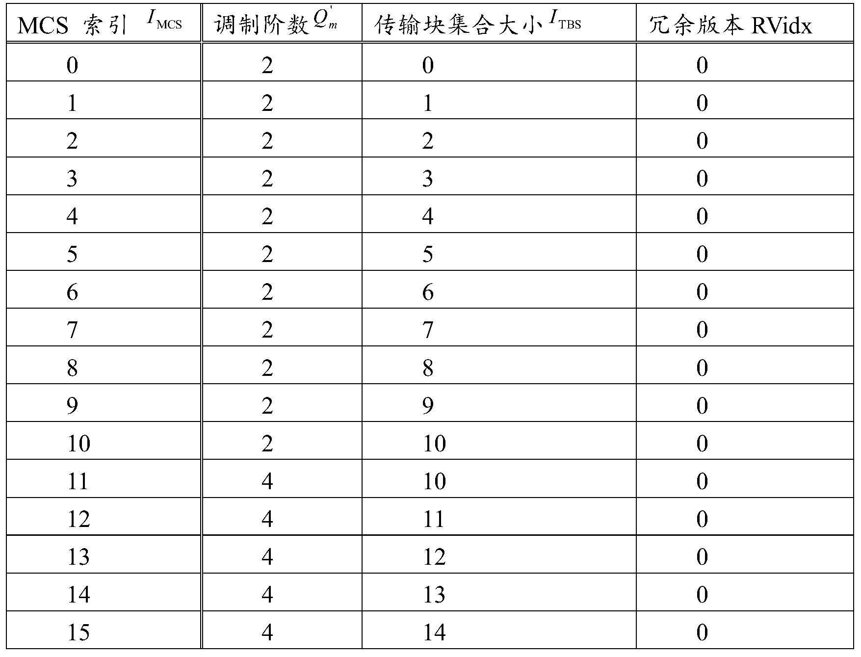

因此,本发明实施例中提到的MCS与门限值MCS_1,MCS_2,MCS_3的比较,实际上是I
MCS与门限值MCS_1,MCS_2,MCS_3的比较。
应理解,表4中对于I
MCS为索引值的取值仅为举例,该索引值可以根据系统设计需求设定为其他的取值,只要能用来表示索引到相应的MCS即可,本发明实施例不对I
MCS的取值并不限定。
频域维度:
关于PTRS在频域上的映射,承载PTRS的子载波分布在用户调度带宽内,例如:可以以资源块RB或者资源束RB为粒度映射,或者其他粒度,比如资源元素(resource element,RE)映射。用户调度带宽(简称“调度带宽”或“调度资源”)可以是调度给用户的用于传输用户的数据业务和控制信号的带宽。在频域上,PTRS可以占据多个RB或者每隔几个RB映射一个PTRS。
调度带宽,由网络设备分配给终端设备的一段时频资源。通常地,调度带宽由DCI指示给终端设备。可用带宽为调度带宽不包括先占带宽(或者为调度带宽排除先占带宽,或者减去先占带宽)。其中,先占带宽是指当分配给终端设备的时频资源中一部分资源被其他信号占用,该其他信号所占用的带宽为先占带宽。先占带宽也可以称为冲突带宽,被占用带宽。可用带宽也可以称为剩余带宽、有效带宽。
如图6A所示,假设分配给终端设备的调度资源为时域上7个符号,频域上40个RB的时频资源,其中,每个RB在时域上占用1个OFDM符号,频域上占用12个子载波。RB可以为资源块(Resource Block,RB),或者资源束(Resource Bundle,RB)。
其中,时域上第3、4、5、6符号、频域上第9~32个RB被同步块(Synchronization Signal Block,SS block)占用,即图4中示出的先占带宽,那么第1个OFDM符号至第7个OFDM符号上的可用带宽分别为:
{40RB,40RB,16RB,16RB,16RB,16RB,40RB}。可选地,确定调度带宽中的可用带宽,包括:
调度带宽减去先占带宽和预留带宽,为可用带宽。
预留带宽,标识网络设备预留的、未来可能会用于传输某些特定信号的时频资源。
如图6B所示,假设分配给终端的调度资源为时域上7个符号,频域上40个RB的时频资源,其中,每个RB在时域上占用1个OFDM符号,频域上占用12个子载波。
其中,时域上第3、4、5、6符号、频域上第9~32个RB被SS block占用即图5中示出的先占带宽,另外,时域上第1个符号属于预留带宽,那么每个符号上的可用带宽分别为:
{0RB,40RB,16RB,16RB,16RB,16RB,40RB}。
本发明实施例提供的参考信号的配置方法可以适用当分配给终端设备的调度带宽(或者称为调度资源)内的部分OFDM符号上存在时频资源被其他信号占用的场景。所述的其他信号可以是下行信号(适用该方法应用于下行传输的场景)还可以是上行信号(对应该方法应用于上行传输的场景)。其中,下行信号可以是以下的一种或多种:
同步块(Synchronization Signal block,SS block)、物理下行控制信道(Physical Downlink Control Channel,PDCCH)、增强物理下行控制信道(Enhanced Physical Downlink Control Channel,EPDCCH)、物理广播信道(Physical Broadcast Channel,PBCH)、主同步信号(Primary Synchronization Signal,PSS)、辅同步信号(Secondary Synchronization Signal,SSS)、解调参考信号(Demodulation Reference Signal,DMRS)、信道状态信息参考信号(Channel State Information Reference Signal,CSI-RS)。
进一步的,当上述下行信号为CSI-RS时,由于CSI-RS占用的时频资源可能是不连续的,先占带宽为CSI-RS在频域上占用的资源元素(Resource Element,RE)RE数所等效的带宽。也就是说,先占带宽为取整(NumRE/12),其中NumRE表示CSI-RS在频域上占用的RE数,取整可以为向上取整、向下取整或四舍五入。
上行信号可以是以下的一种或多种:
物理上行控制信道(Physical Uplink Control Channel,PUCCH)、解调参考信号DMRS、探测参考信号(Sounding Reference Signal,SRS)。
映射PTRS时,为了防止与先占带宽冲突或者碰撞,可以映射到可用带宽上,频域密度与可用带宽的隐式关联准则可以如表5所示:
表5
| 可用带宽 | 频域密度 |
| 0<=NRB<NRB1 | 不映射PTRS |
| NRB1<=NRB<NRB2 | FD1 |
| NRB2<=NRB<NRB3 | FD2 |
| NRB3<=NRB<NRB4 | FD3 |
| NRB4<=NRB<NRB5 | FD4 |
| NRB5<=NRB | FD5 |
其中,NRB1,NRB2,NRB3,NRB4,NRB5为预定或者预设置的带宽门限值。
可选地,频域密度FD的取值可以是0,1/2,1/4,1/8,1/16,其中1/N表示每隔N个RB映射一个PTRS。
可选地,频域密度还可以称为频域个数,频域个数是指在可用带宽上,映射PTRS符号 的个数。比如,频域个数与可用带宽的隐式关联准则还可以如表6所示:
表6
| 可用带宽 | 频域个数 |
| 0<=NRB<NRB1 | 不映射PTRS |
| NRB1<=NRB<NRB2 | 1 |
| NRB2<=NRB<NRB3 | 2 |
| NRB3<=NRB<NRB4 | 4 |
| NRB4<=NRB<NRB5 | 8 |
| NRB5<=NRB | 16 |
其中,NRB1,NRB2,NRB3,NRB4,NRB5为预定或者预设置的带宽门限值。
应理解,表6中的取值1、2、4、8、16仅为示例,本发明不予限定。
应理解,表5、6仅为表示对应关系列表的一种举例,上述表格行数可以增减,比如:直接增加或减少上述表格的行数;通过另左边的值等于右边的值,无效对应行;另外表格只是一种对应关系列表list的一种表现形式,还可以采用公式,如式(1)。本领域的技术人员可以理解,也可以采用其他的形式来表示对应关系列表List,本申请并不做限定。

示例性地,假设基站预配置UE1的PTRS,通过表3获知时域密度为1/2,即每2个符号映射一个PTRS,以图7A为例,即在第1、3、5、7个符号上需要映射PTRS。
比如,根据计算得出第1、3、5、7个符号上的可用带宽分别为10RB、8RB、8RB、10RB。如图7A所示。
第1个和第7个符号的可用带宽为10RB,假设落入表5中的区间为:NRB2<=NRB<NRB3,对应的频域密度为FD2,比如,1/4。
第3个和第5个符号的可用带宽为8RB,假设落入表5中的区间为:NRB1<=NRB<NRB2,对应的频域密度为FD1,比如,1/2。
映射的PTRS的图案如图7A所示:
在第一符号上,分别第1个RB,第5个RB,第9个RB上映射PTRS。
在第三个符号上,分别在第1个RB,第3个RB,第7个RB,第9个RB上映射PTRS。
同样在第五个符号上,分别在第1个RB,第3个RB,第7个RB,第9个RB上映射PTRS。
在第7个符号上,分别在第1个RB,第5个RB,第9个RB上映射PTRS。
又比如,根据计算得出第1、3、5、7个符号上的可用带宽分别为0RB、8RB、8RB、10RB。如图7B所示。
根据表8得知,第一个符号的可用带宽为0RB时,不映射PTRS;
第3个符号上的可用带宽为8RB时,落入表5中的区间为:NRB1<=NRB<NRB2,对应的频域密度为FD1,比如,1/2。
同样第,第5个符号上的可用带宽为8RB,频域密度也为1/2。
第7个符号上的可用带宽为10RB时,落入表5中的区间为:NRB2<=NRB<NRB3,对应的频域密度为FD2,比如,1/4。
映射的PTRS的图案(pattern)如图7B所示:
在第一符号上,不映射PTRS。
在第三个符号上,分别在第1个RB,第3个RB,第7个RB,第9个RB上映射PTRS。
同样在第五个符号上,分别在第1个RB,第3个RB,第7个RB,第9个RB上映射PTRS。
在第7个符号上,分别在第一个RB,第5个RB,第9个RB上映射PTRS。
需要说明的是,在第3个符号和第5个符号上,当频域密度为1/2时,表示在第1/3/5/7、9个RB上映射PTRS,但是第4和第5个RB是先占带宽,因此,以每两个RB映射一个PTRS时,是第1,3,7,9RB上映射PTRS。
本实施例中,建立调度或可用RB与PTRS频域密度的对应关系,基于调度或可用RB来确定PTRS的频域密度。所述调度或可用RB,是指调度或可用带宽上包括的RB。在一种可能的实现方式中,所述调度或可用RB可以通过RB的索引信息或者调度或可用RB的个数来体现。例如N个调度或可用RB,RB的索引信息可以为0~N-1或者1~N,N为大于等于1的整数。
另外,在频域上,所述调度或可用带宽还可以通过调度或可用RB来标识。例如,可以通过调度或可用RB的索引或调度或可用RB的个数来标识。本实施例中,建立调度或可用RB于PTRS频域密度的对应关系。例如,调度或可用RB被划分为一个或多个区间,每个区间对应一个PTRS的频域密度。
例如,网络设备预先设置多个调度或可用资源块RB的索引区间与多个PTRS频域密度的对应关系,如表7所示:
表7
| 调度或可用资源块的索引区间 | PTRS频域密度 |
| 0<=I RB<I RB1 | 不设置PTRS |
| I RB1<=I RB<I RB2 | FD 1 |
| I RB2<=I RB<I RB3 | FD 2 |
| I RB3<=I RB<I RB4 | FD 3 |
| I RB4<=I RB | FD 4 |
如表7中,I
RB1、I
RB2、I
RB3和I
RB4分别表示不同PTRS频域密度对应的调度或可用RB的门限值的索引。表7给出调度或可用RB被划分为5个区间的例子,本领域的技术人员可以理解,根据系统需要,调度或可用RB可以被配置成一个或一个以上的区间,从而建立每个区间与PTRS频域密度的对应关系。
调度或可用RB的索引可以是指资源块的编号或相对编号。如图8A和图8B所示的相对资源块RB与虚拟资源块VRB/物理资源块PRB的关系示意图,作为一种实现方式,在图8A中,调度或可用资源块的相对编号是指调度的虚拟资源块(virtual resource block,VRB)编号排序后的序列号;作为另一种实现方式,在图8B中,调度或可用资源块的相对编号为调度的 物理资源块(physical resource block,PRB)编号排序后的序列号。其中,VRB和PRB的映射关系可以由网络设备指示给终端设备。与相对编号相对的一个概念是绝对编号,资源块的绝对编号则是VRB或PRB的未排序的编号。
网络设备可以发送PTRS的频域密度与调度或可用RB的对应关系(也可以不发送,而是预存储在终端设备内部)、调度信息给终端设备。该调度信息包括调度带宽和MCS等信息。关于调度信息的发送,这里需要从两个方面进行说明:对于下行传输,网络设备在发送OFDM符号之前发送调度信息,调度信息也可以与OFDM符号同时发送。对于上行传输,网络设备需要在终端设备发送OFDM符号之前发送调度信息给终端设备。
发送端设备根据MCS确定PTRS的时域密度,并根据调度信息进行调度或可用RB的区间划分。如图9给出了PTRS调度或可用RB的区间划分和频域映射的一个举例。如图9所示,最上面的32个RB(RB0-RB31)被划分成5个RB索引区间,中间的30个RB(RB0–RB 29)被划分成5个RB索引区间,最下面的14个RB(RB0–RB13)被划分成4个RB索引区间。各个RB索引区间对应的PTRS频域密度可不相同。
另一种可能的实现方式中,PTRS在频域上的配置还考虑频域偏移量。可以建立RB区间(例如,RB索引区间、或RB数量区间)与频域偏移量的对应关系。例如每个RB区间对应一个所述频域偏移量。下面以RB索引区间为例进行说明。
在一种可能的设计中,不同的RB索引区间可对应不同的频域偏移量,给定RB索引区间内的频域偏移量可以通过计算获得,例如,频域偏移量可以是偏移值与所述RB索引区间对应的频域密度的取余。如假设I
RB1=2,I
RB2=4,I
RB3=8,I
RB4=16,则当调度带宽分别为32RB、30RB、14RB时,PTRS的映射如图9所示。其中,偏移值Offset的最大值可由当前调度带宽所能配置的最小频域密度决定,如每8个RB映射一个PTRS时,最大偏移值为7个RB。则调度/调度或可用/有效带宽内的PTRS频域偏移量为mod(Offset,FDi)。如图9所示,Offset为7时:
编号为2~3的RB,PTRS的频域偏移量为mod(7,1)=0;
编号为4~7的RB,PTRS的频域偏移量为mod(7,2)=1;
编号为8~15的RB,PTRS的频域偏移量为mod(7,4)=3;
编号为16~31的RB,PTRS的频域偏移量为mod(7,8)=7。
在另一种可能的设计中,每个RB索引区间的频域偏移量是预定值(例如为,固定值,或者是可配置的值)。可预先定义该预定值或通过信令配置该预定值。所述信令包括RRC、媒体接入控制控制单元和下行控制信息等。
在又一种可能的设计中,建立每个RB索引区间的频域偏移量与RB索引区间对应关系表。例如可以通过协议定义,或者预先存储、或者通过信令配置所述对应关系表所述信令包括RRC、媒体接入控制控制单元和下行控制信息等。
基于上面描述,可以确定PTRS的时域密度、频域密度以及频域偏移量。基于PTRS的时域密度、频域密度以及频域偏移量,将PTRS映射到OFDM符号上。
可以看出,在图9中,对同一个调度带宽,不同的RB索引区间映射不同频域密度的PTRS,使得调度带宽的每一个RB区间索引区间内的PTRS是均匀分布的,可降低与其他RS或信道冲突处理的难度;并且避免了因调度带宽的增加,频域PTRS个数反而减少的情况。
需要说明的是,终端设备可以与网络侧协商关于PTRS的时频配置。例如,终端设备可以反馈或建议如何配置PTRS,网络设备通过信令进行修改或确认,修改或确认的信令可以是 RRC、MAC-CE和DCI等。
在S104部分,发送端设备发送包含映射了PTRS的OFDM符号的信号给接收端设备。接收端设备接收到所述包含了映射了PTRS的OFDM符号信号后,获取PTRS。
S105之后,该方法还可以包括步骤:根据所述PTRS的接收信号进行公共相位误差估计。具体地,利用接收到的PTRS信号A*exp(1j*theta)+noise与发射的PTRS信号A相除或乘以共轭,则可估计出CPE(theta),其中噪声的影响可以通过平均多个PTRS的结果降低。
根据本发明实施例提供的一种通信方法,通过根据调度或可用资源块(如调度或可用RB的索引或调度或可用RB的个数)确定PTRS的频域密度,根据PTRS的时域密度、频域密度及频域偏移量映射PTRS到OFDM符号上,可避免PTRS的个数在调度带宽的门限值附近发生跳变,兼顾了公共相位误差估计的准确性和频谱效率,并能在调度或可用带宽内均匀地映射PTRS,从而合理地配置了PTRS。
需要说明的是,由于虚拟资源块(Virtual Resource Block,VRB)或物理资源块(Physical Resource Block,PRB)的调度可以是离散的也可以是连续的,为了保证调度或可用带宽上映射的PTRS数,上述RB的编号为分配给终端的VRB编号或PRB编号从小到大或从大到小或其他规则排列后的相对编号。举例:如分配给终端的PRB编号为PRB0,PRB1,PRB2,PRB3,PRB6,PRB7,PRB10,PRB11,PRB14,PRB15,PRB16,PRBG17,PRB18,PRB19,PRB22,PRB23,共16个RB,假设其对应的频域密度为1/4,则总共应有4个PTRS,若按PRB的绝对编号即绝对编号为0,4,8,12,…的RB上映射PTRS,则仅有PRB0,PRB16上有PTRS,因此需按PRB的相对编号0,1,2,…15映射PTRS,即PRB0(对应相对编号0),PRB6(对应相对编号4),PRB14(对应相对编号8),PRB18(对应相对编号12)上映射PTRS。
上述隐式关联准则、PTRS的起始位置仅为举例,本发明不限于此。上述其他信道或同步块仅为举例,除了PDCCH,PBCH,PSS,SSS,EPDCCH,还可以有PUCCH,机器类通信PDCCH(Machine Type Communication PDCCH,MPDCCH)等其他占用不可忽略资源的信道或信号或RS。本发明不限于此。上述被占用的资源均是连续的,实际情况中,也可以是非连续的,如EPDCCH,若是非连续的,则可以先在调度或可用带宽上确定PTRS的位置后再映射至虚拟资源或物理资源。
通过基于符号的PTRS频域密度、PTRS频域个数、频域位置的确定方法和PTRS的映射方法,可以使得每个符号上的PTRS开销和引入PTRS带来的性能提升达到最佳组合,最大化频谱效率。
当该图3A和图3B中的方法对应下行时,可选地,所述方法还包括:
发送用于指示调度带宽的信息至终端设备。
可选地,所述方法还包括:
发送用于指示先占带宽或者调度或可用带宽的信息至终端设备。
可选地,所述方法还包括:
发送用于指示预留带宽的信息至终端设备。
相对应地,当该方法对应上行时,可选地,所述方法300还包括:
接收来自网络设备的指示调度带宽的信息。
可选地,所述方法还包括:
接收来自网络设备的指示先占带宽或者调度或可用带宽的信息。
可选地,所述方法还包括:
接收来自网络设备的指示预留带宽的信息。
其中,网络设备为终端设备分配或者指示调度带宽、先占带宽、调度或可用带宽、预留带宽时,需要通过下行信令指示该调度带宽,比如下行控制信息(Downlink Control Information,DCI)。根据现有的LTE的标准协议,网络设备指示带宽的方法有3种类型,分别为资源分配方式0(Type 0)、资源分配方式1(Type1)、资源分配方式2(Type2)。具体使用哪些类型取决于所选的DCI format以及DCI内相关bit的配置。每种DCI format支持哪些类型,以及有哪些与资源分配相关的bit,可以参考LTE系统中TS36.212的5.3.3章节相关的描述,也可以是重新进行协议规定,或者重新设计DCI format来进行配置。
比如,下面简单介绍一下资源分配方式0。
采用资源分配方式0的DCI有DCI1、DCI2、DCI2A、DCI2B,这些DCI里都有个资源分配的字段,用于表示哪些RB是分配给这个UE的。比如,如图10中的DCI2A格式,当使用资源分配方式0的时候,有
 个比特的bitmap表用于表示RB的分配情况,
 是系统带宽的RB总个数,参数P则与系统带宽大小有关,具体见后文描述,
 表示向上取整。
在RB资源分配方式0中,所有的RB资源构成不同的资源块组(Resource Block Group,RBG),因此分配方式0就是以RBG为基本单位进行分配的。在这种分配方式里,DCI中的资源分配字段将使用一个bitmap表来分配RB资源,这个bitmap表的每个bit位就表示一个RBG。每个RBG由P个RB组成,P值与下行带宽相关,如下表8所示:
表8
| System Bandwidth | RBG Size(P) |
| ≤10 | 1 |
| 11-26 | 2 |
| 27-63 | 3 |
| 64-110 | 4 |
比如基于15k的子载波间隔,下行是20MHz的带宽
 那么如果按照资源分配方式0分配RB资源,每个RBG将包括4个RB(P=4)。如果是1.4MHz的带宽
 那么每个RBG就只包括1个RB。
不同的带宽,资源分配方式0所能使用的RBG个数也是固定的。如果用变量N
RBG来表示这个值的话,
 其中
其中
 表示N
RBG向上取整。每个资源分配方式0的DCI,都对应着一个N
RBG比特长度的bitmap资源分配表,这个bitmap分配表被编码到DCI码流中,UE从这个分配表就可以推导出该PDSCH使用的RB资源。
表示N
RBG向上取整。每个资源分配方式0的DCI,都对应着一个N
RBG比特长度的bitmap资源分配表,这个bitmap分配表被编码到DCI码流中,UE从这个分配表就可以推导出该PDSCH使用的RB资源。
比如,如图10所示,3MHz的下行带宽,子载波间隔为15k时它的RB个数
 P=2,因此
 但是需要注意,如果是
 的系统带宽,它的最后一个RBG的大小和其它的RBG大小是不一样的:最后一个RBG包含的

 而其它位置的RBG包含的RB个数=P个。比如3MHz下行带宽,除了最后一个RBG,其他
 个RBG,其中floor()表示向下取整,每个RBG 都有2个RB,此时这7个RBG共占用了7*2=14个RB,小于整个带宽的15个RB,因此最后一个RBG包含的
 个。最后一个RB14构成了一个RBG7(RBG编号从0开始)。
另外,bitmap表有高低位问题。现有标准协议明确规定,RBG
0对应着这个bitmap的高位即MSB,而
 则对应着这个bitmap表的低位即LSB。如果UE解码到某个bit位=1,则表示对应的RBG分配给了这个UE。比如3M带宽时,bitmap表占用的bit位数N_RBG=ceil(15/2)=8,其中ceil表示向上取整,bitmap码流=二进制Bin(00001011),那么表示该UE使用的RBG资源组分别是RBG4、RBG6和RBG7,因此使用的RB-ID分别是:RB8-RB9,RB12-RB14。所以说,分配方式0可以分配离散的RB资源,只是带宽越大,分配的RB粒度P就越粗。
本发明实施例所提到的指示调度带宽的方法、或者指示先占带宽的方法、或者指示预留带宽的方法可以参考LTE系统现有标准中所述的三种方法的任一种方法,这里不再赘述。
图11为本发明实施例提供的另一种通信方法的交互流程示意图,该方法可包括以下步骤:
S201、发送端设备确定映射PTRS的时域密度。
S202、所述发送端设备确定频域上映射PTRS的个数L。
S203、所述发送端设备根据以下公式确定N
RB个资源块RB上的映射L个PTRS的频域RB编号i为:
其中,k
1为偏移量,且k
1为整数。
S204、所述发送端设备根据所述时域密度和所述PTRS的频域RB编号(或索引),将所述PTRS映射到OFDM符号上。
S205、所述发送端设备发送包含映射了PTRS的OFDM符号的信号。
S206、所述接收端设备接收包含映射了PRTS的OFDM符号的信号,并获取所述PTRS。
PTRS在时域上的配置可参考前述实施例的描述,在此不再赘述。
本实施例中,可以采用表7所示的PTRS的频域个数与调度带宽的对应关系,其中频域密度可表示为
 也可以对于调度带宽的区间划分可以采用更细或者更粗的粒度。例如,表7所示的对应关系表格的行数可以增加或减少,例如(a)增加或减少上述表格的行数;(b)令左边的值等于右边的值,无效对应行。
可以理解,表格只是表现对应关系列表list的一种表现形式,还可以使用公式来表示对应关系列表list,例如,如公式(3)所示。本领域的技术人员可以理解,也可以采用其他的形式来表示对应关系列表List,本申请并不做限定。

然而,本实施例采用公式(2)确定映射PTRS的RB编号。例如,当N
RB=32,L=8,k
1=0时、当N
RB=30,L=8,k
1=4时以及当N
RB=14,L=4,k
1=1时,采用公式(2)计算出RB编号,其映射了PTRS的RB的示意图如图12所示。对比图10与图1可以看出,图12中PTRS的映射比图1中PTRS的映射更均匀。在图12中,频域上任意两个映射了PTRS的RB之间间隔的RB个数相等。应理解,图中的频域密度仅为示意,本发明不限于此。
其中,该RB编号可以为调度的VRB编号排序后的序列号,或所述RB编号为调度的PRB编号排序后的序列号。
发送端设备根据所述时域密度和所述PTRS的RB编号,将所述PTRS映射到OFDM符号上。
S204,S205部分可以参照与前述S104,S105部分的相关描述,在此不再赘述。
上面以RB为粒度单位为例,对PTRS的映射进行了说明,可以理解的是,也可以参照RB粒度映射PTRS的方法,以其他粒度单位进行映射PTRS。
在一种实现方式中,S202可以通过以下方式实现:
根据以下公式确定N
RB个资源块上的L个PTRS的频域资源单元RE编号Index
RE为:
其中,I
DMRS为DMRS的频域间隔;
k
2为RE的偏移量,

由于映射PTRS时,一般应与DMRS位于同一子载波上,即PTRS的映射位置应与其关联的DMRS端口的DMRS位置相关。而一个PTRS只占用一个资源单元,因此,从资源单元的级别映射PTRS时,采用公式(4)确定PTRS的RE编号,可保证PTRS的映射位置与DMRS位置相关。从资源单元的级别进行PTRS频域的映射,可以更准确地进行PTRS的配置。
在另一个实现方式中,步骤S202还可以通过以下方式实现:
根据以下公式确定N
RB个资源块上的L个PTRS的频域资源单元RE编号Index
RE为:
其中,k
3为RE的偏移量,

由于一个资源块包括12个资源单元,且一个PTRS只占用一个资源单元,因此,从资源单元的级别进行PTRS频域的映射,可以更准确地进行PTRS的配置。从RE基本进行PTRS的映射,即在公式(2)的基础上,将N
RB乘以12,即变换为基本单位为RE。同样地,k
3的取值也是RE级别的。
根据本发明实施例提供的通信方法,可以PTRS的均匀分布,从而可以较容易的通过设置偏移量避免PTRS与其它参考信号的映射位置冲突,并使得终端设备间干扰随机化操作简单。
本申请实施例可以根据上述方法示例对发送端设备或者接收端设备进行功能模块的划分,例如,可以对应各个功能划分各个功能模块,也可以将两个或两个以上的功能集成在一个处理模块中。上述集成的模块既可以采用硬件的形式实现,也可以采用软件功能模块的形式实现。需要说明的是,本申请实施例中对模块的划分是示意性的,仅仅为一种逻辑功能划分,实际实现时可以有另外的划分方式。下面以采用对应各个功能划分各个功能模块为例进行说明。
本申请实施例还提供一种通信装置,该通信装置可以是终端设备也可以是可用于终端设 备的芯片。该通信装置可以用于执行图3A、图3B、图11中由终端设备所执行的步骤。
当所述通信装置为终端设备时,图13示出了一种简化的终端设备结构示意图。便于理解和图示方便,图13中,终端设备以手机作为例子。如图13所示,终端设备包括处理器、存储器、射频电路、天线以及输入输出装置。处理器主要用于对通信协议以及通信数据进行处理,以及对终端设备进行控制,执行软件程序,处理软件程序的数据等。存储器主要用于存储软件程序和数据。射频电路主要用于基带信号与射频信号的转换以及对射频信号的处理。天线主要用于收发电磁波形式的射频信号。输入输出装置,例如触摸屏、显示屏,键盘等主要用于接收用户输入的数据以及对用户输出数据。需要说明的是,有些种类的终端设备可以不具有输入输出装置。
当需要发送数据时,处理器对待发送的数据进行基带处理后,输出基带信号至射频电路,射频电路将基带信号进行射频处理后将射频信号通过天线以电磁波的形式向外发送。当有数据发送到终端时,射频电路通过天线接收到射频信号,将射频信号转换为基带信号,并将基带信号输出至处理器,处理器将基带信号转换为数据并对该数据进行处理。为便于说明,图13中仅示出了一个存储器和处理器。在实际的终端产品中,可以存在一个或多个处理器和一个或多个存储器。存储器也可以称为存储介质或者存储设备等。存储器可以是独立于处理器设置,也可以是与处理器集成在一起,本申请实施例对此不做限制。
在本申请实施例中,可以将具有收发功能的天线和射频电路视为终端设备的收发单元,将具有处理功能的处理器视为终端设备的处理单元。如图13所示,终端设备包括收发单元1301和处理单元1302。收发单元也可以称为收发器、收发机、收发装置等。处理单元也可以称为处理器,处理单板,处理模块、处理装置等。处理单元可以是中央处理器(英文:central processing unit,缩写:CPU),网络处理器(英文:network processor,缩写:NP)或者CPU和NP的组合。处理单元还可以进一步包括硬件芯片。上述硬件芯片可以是专用集成电路(英文:application-specific integrated circuit,缩写:ASIC),可编程逻辑器件(英文:programmable logic device,缩写:PLD)或其组合。上述PLD可以是复杂可编程逻辑器件(英文:complex programmable logic device,缩写:CPLD),现场可编程逻辑门阵列(英文:field-programmable gate array,缩写:FPGA),通用阵列逻辑(英文:generic array logic,缩写:GAL)或其任意组合。可选的,可以将收发单元1301中用于实现接收功能的器件视为接收单元,将收发单元1301中用于实现发送功能的器件视为发送单元,即收发单元1301包括接收单元和发送单元。收发单元有时也可以称为收发机、收发器、或收发电路等。接收单元有时也可以称为接收机、接收器、或接收电路等。发送单元有时也可以称为发射机、发射器或者发射电路等。
例如,在一种实现方式中,处理单元1301,用于执行图3A中步骤306,和/或本申请中的其他步骤。收发单元1302执行图3A中的步骤305中终端侧的接收操作,和/或本申请中的其他步骤。
例如,在另一种实现方式中,处理单元1301,用于执行图3A中步骤301-304,和/或本申请中的其他步骤。收发单元1302执行图3A中的步骤304中终端侧的发送操作,和/或本申请中的其他步骤。
例如,在另一种实现方式中,处理单元1301,用于执行图3B中步骤105,和/或本申请中的其他步骤。收发单元1302执行图3B中的步骤105中终端侧的接收操作,和/或本申请中的其他步骤。
例如,在另一种实现方式中,处理单元1301,用于执行图3B中步骤101-104,和/或本 申请中的其他步骤。收发单元1302执行图3B中的步骤104中终端侧的发送操作,和/或本申请中的其他步骤。
例如,在另一种实现方式中,处理单元1301,用于执行图11中步骤206,和/或本申请中的其他步骤。收发单元1302执行图11中的步骤206中终端侧的接收操作,和/或本申请中的其他步骤。
例如,在另一种实现方式中,处理单元1301,用于执行图11中步骤201-205,和/或本申请中的其他步骤。收发单元1302执行图11中的步骤205中终端侧的发送操作,和/或本申请中的其他步骤。
可选地,终端设备还包括存储单元,用于保存对应关系列表,
所述列表包括至少一个RB索引区间和至少一个PTRS的频域密度,其中,所述RB索引区间与所述PTRS频域的密度具有一一对应关系;或者
所述列表包括至少一个RB的个数区间和至少一个PTRS的频域密度,其中,所述RB的个数区间与所述PRTS的频域密度具有一一对应关系;或者
所述列表包括至少一个RB索引区间,至少一个PTRS的频域密度,至少一个频域偏移量,其中所述RB索引区间,所述PRTS的频域密度,所述频域偏移量具有一一对应关系;或者
所述列表包括至少一个RB的个数区间,至少一个PTRS的频域密度,至少一个频域偏移量,其中所述RB的个数区间,所述PRTS的频域密度,所述频域偏移量具有一一对应关系。
当所述通信装置为芯片时,该芯片包括收发单元和处理单元。其中,收发单元可以是输入输出电路、通信接口;处理单元为该芯片上集成的处理器或者微处理器或者集成电路。
本申请实施例还提供一种通信装置,该通信装置可以是网络设备也可以是芯片。该通信装置可以用于执行图3A、图3B以及图11中由网络设备所执行的步骤。
当该通信装置为网络设备时,具体地,例如为基站。图14示出了一种简化的基站结构示意图。基站包括1401部分以及1402部分。1401部分主要用于射频信号的收发以及射频信号与基带信号的转换;1402部分主要用于基带处理,对基站进行控制等。1401部分通常可以称为收发单元、收发机、收发电路、或者收发器等。1402部分通常是基站的控制中心,通常可以称为处理单元,用于控制基站执行上述图中关于接收端设备所执行的步骤。具体可参见上述相关部分的描述。
1401部分的收发单元,也可以称为收发机,或收发器等,其可以包括天线和射频单元,其中射频单元主要用于进行射频处理。可选的,可以将1401部分中用于实现接收功能的器件视为接收单元,将用于实现发送功能的器件视为发送单元,即1401部分包括接收单元和发送单元。接收单元也可以称为接收机、接收器、或接收电路等,发送单元可以称为发射机、发射器或者发射电路等。
1402部分可以包括一个或多个单板,每个单板可以包括一个或多个处理器和一个或多个存储器,处理器用于读取和执行存储器中的程序以实现基带处理功能以及对基站的控制。若存在多个单板,各个单板之间可以互联以增加处理能力。作为一种可选的实施方式,也可以是多个单板共用一个或多个处理器,或者是多个单板共用一个或多个存储器,或者是多个单板同时共用一个或多个处理器。
例如,在一种实现方式中,处理单元1402用于处理图3A中步骤301-304的操作;收发 单元用于执行图3A中步骤304中网络设备侧的发送操作。
在另一种实现方式中,处理单元1402用于处理图3A中步骤306的操作;收发单元用于执行图3A中步骤305中网络设备侧的接收操作。
在另一种实现方式中,处理单元1402用于处理图3B中步骤101-104的操作;收发单元用于执行图3B中步骤104中网络设备侧的发送操作。
在另一种实现方式中,处理单元1402用于处理图3B中步骤105的操作;收发单元用于执行图3B中步骤105中网络设备侧的接收操作。
在另一种实现方式中,处理单元1402用于处理图11中步骤201-104的操作;收发单元用于执行图11中步骤205中网络设备侧的发送操作。
在另一种实现方式中,处理单元1402用于处理图11中步骤206的操作;收发单元用于执行图11中步骤206中网络设备侧的接收操作。
可选地,网络设备还包括存储单元,用于保存对应关系列表,
所述列表包括至少一个RB索引区间和至少一个PTRS的频域密度,其中,所述RB索引区间与所述PTRS频域的密度具有一一对应关系;或者
所述列表包括至少一个RB的个数区间和至少一个PTRS的频域密度,其中,所述RB的个数区间与所述PRTS的频域密度具有一一对应关系;或者
所述列表包括至少一个RB索引区间,至少一个PTRS的频域密度,至少一个频域偏移量,其中所述RB索引区间,所述PRTS的频域密度,所述频域偏移量具有一一对应关系;或者
所述列表包括至少一个RB的个数区间,至少一个PTRS的频域密度,至少一个频域偏移量,其中所述RB的个数区间,所述PRTS的频域密度,所述频域偏移量具有一一对应关系。
所述通信装置可以为芯片,该芯片包括收发单元和处理单元。其中,收发单元可以是芯片的输入输出电路或通信接口;处理单元为该芯片上集成的处理器或者微处理器或者集成电路。所述芯片可以应用于上述发送端设备或接收端设备,并支持所述发送端装置或接收端设备执行上述方法。
上述提供的任一种通信装置中相关内容的解释及有益效果均可参考上文提供的对应的方法实施例,此处不再赘述。
在上述实施例中,可以全部或部分地通过软件、硬件、固件或者其任意组合来实现。当使用软件程序实现时,可以全部或部分地以计算机程序产品的形式来实现。该计算机程序产品包括一个或多个计算机指令。在计算机上加载和执行计算机程序指令时,全部或部分地产生按照本申请实施例所述的流程或功能。所述计算机可以是通用计算机、专用计算机、计算机网络、或者其他可编程装置。所述计算机指令可以存储在计算机可读存储介质中,或者从一个计算机可读存储介质向另一个计算机可读存储介质传输,例如,所述计算机指令可以从一个网站站点、计算机、服务器或者数据中心通过有线(例如同轴电缆、光纤、数字用户线(Digital Subscriber Line,DSL))或无线(例如红外、无线、微波等)方式向另一个网站站点、计算机、服务器或数据中心进行传输。所述计算机可读存储介质可以是计算机能够存取的任何可用介质或者是包含一个或多个可以用介质集成的服务器、数据中心等数据存储设备。所述可用介质可以是磁性介质(例如,软盘、硬盘、磁带),光介质(例如,DVD)、或者半导体介质(例如固态硬盘(Solid State Disk,SSD))等。
尽管在此结合各实施例对本申请进行了描述,然而,在实施例所要求保护的本申请过程中,本领域技术人员可理解并实现所述公开实施例的其他变化。
本发明实施例还提供一种芯片,该芯片包括通信接口与处理器,该处理器用于控制通信接口接收或发送信号,并用于处理通信接口接收到的信号或生成通信接口待发送的信号。该处理器用于执行上述方法实施例提供发送端设备或接收端设备的各种处理功能,例如确定时域密度,频域密度等,具体参见上述方法实施例中的描述。
可选地,该芯片还包括存储模块,该存储模块存储有指令。该处理模块通过读取该存储模块存储的指令,来执行相关操作,以及控制该通信接口进行相关的收发操作。
应理解,在本申请的各种实施例中,上述各过程的序号的大小并不意味着执行顺序的先后,各过程的执行顺序应以其功能和内在逻辑确定,而不应对本发明实施例的实施过程构成任何限定。
本领域普通技术人员可以意识到,结合本文中所公开的实施例描述的各示例的单元及算法步骤,能够以电子硬件、或者计算机软件和电子硬件的结合来实现。这些功能究竟以硬件还是软件方式来执行,取决于技术方案的特定应用和设计约束条件。专业技术人员可以对每个特定的应用来使用不同方法来实现所描述的功能,但是这种实现不应认为超出本申请的范围。
所属领域的技术人员可以清楚地了解到,为描述的方便和简洁,上述描述的系统、装置和单元的具体工作过程,可以参考前述方法实施例中的对应过程,在此不再赘述。
在本申请所提供的几个实施例中,应该理解到,所揭露的系统、装置和方法,可以通过其它的方式实现。例如,以上所描述的装置实施例仅仅是示意性的,例如,所述单元的划分,仅仅为一种逻辑功能划分,实际实现时可以有另外的划分方式,例如多个单元或组件可以结合或者可以集成到另一个系统,或一些特征可以忽略,或不执行。另一点,所显示或讨论的相互之间的耦合或直接耦合或通信连接可以是通过一些接口,装置或单元的间接耦合或通信连接,可以是电性,机械或其它的形式。
所述作为分离部件说明的单元可以是或者也可以不是物理上分开的,作为单元显示的部件可以是或者也可以不是物理单元,即可以位于一个地方,或者也可以分布到多个网络单元上。可以根据实际的需要选择其中的部分或者全部单元来实现本实施例方案的目的。
另外,在本申请各个实施例中的各功能单元可以集成在一个处理单元中,也可以是各个单元单独物理存在,也可以两个或两个以上单元集成在一个单元中。
在上述实施例中,可以全部或部分地通过软件、硬件、固件或者其任意组合来实现。当使用软件实现时,可以全部或部分地以计算机程序产品的形式实现。所述计算机程序产品包括一个或多个计算机指令。在计算机上加载和执行所述计算机程序指令时,全部或部分地产生按照本发明实施例所述的流程或功能。所述计算机可以是通用计算机、专用计算机、计算机网络、或者其他可编程装置。所述计算机指令可以存储在计算机可读存储介质中,或者通过所述计算机可读存储介质进行传输。所述计算机指令可以从一个网站站点、计算机、服务器或数据中心通过有线(例如同轴电缆、光纤、数字用户线(digital subscriber line,DSL))或无线(例如红外、无线、微波等)方式向另一个网站站点、计算机、服务器或数据中心进行传输。所述计算机可读存储介质可以是计算机能够存取的任何可用介质或者是包含一个或多个可用介质集成的服务器、数据中心等数据存储设备。所述可用介质可以是磁性介质,(例如,软盘、硬盘、磁带)、光介质(例如,数字通用光盘(digital versatile disc,DVD))、或者 半导体介质(例如固态硬盘(solid state disk,SSD))等。
本领域普通技术人员可以理解实现上述实施例方法中的全部或部分流程,该流程可以由计算机程序来指令相关的硬件完成,该程序可存储于计算机可读取存储介质中,该程序在执行时,可包括如上述各方法实施例的流程。而前述的存储介质包括:只读存储器(read-only memory,ROM)或随机存储存储器(random access memory,RAM)、磁碟或者光盘等各种可存储程序代码的介质。
Claims (24)
- 一种信息传输方法,其特征在于,包括:确定相位跟踪参考信号PTRS的时域密度;根据可用带宽确定相位跟踪参考信号PTRS的频域密度,或者根据调度或可用资源块RB确定相位跟踪参考信号PTRS的频域密度;根据所述时域密度以及所述频域密度将所述PTRS映射到一个或多个正交频分复用OFDM符号;以及发送包含映射了PTRS的OFDM符号的信号。
- 如权利要求1所述的方法,其特征在于,还包括:向接收端设备发送以下一项或多项:用于指示调度带宽的信息;用于指示先占带宽的信息;以及用于指示预留带宽的信息。
- 如权利要求1或2所述的方法,其特征在于,所述根据所述时域密度以及所述频域密度将所述PTRS映射到一个或多个OFDM符号为:根据所述时域密度,所述频域密度,以及频域偏移量将所述PTRS映射到一个或多个OFDM符号。
- 一种信息传输方法,其特征在于,包括:接收一个或多个正交频分复用OFDM符号;确定映射在所述一个或多个OFDM符号上的相位跟踪参考信号PTRS,其中,确定PTRS包括:确定相位跟踪参考信号PTRS的时域密度;以及根据可用带宽确定相位跟踪参考信号PTRS的频域密度,或者根据调度或可用资源块RB确定相位跟踪参考信号PTRS的频域密度。
- 如权利要求4所述的方法,其特征在于,还包括:接收来自发送端设备的以下一项或多项:用于用于指示调度带宽的信息;用于指示先占带宽的信息;以及用于指示预留带宽的信息。
- 如权利要求4或5所述的方法,其特征在于,所述确定PTRS还包括:确定所述PTRS的频域偏移量。
- 如权利要求1至6任一项所述的方法,其特征在于,所述可用带宽为所述调度带宽中不包括先占带宽的部分;或者,所述可用带宽为所述调度带宽中不包括预留带宽的部分;或者所述可用带宽为所述调度带宽中不包括先占带宽和预留带宽的部分。
- 如权利要求7所述的方法,其特征在于,所述先占带宽为以下一种或多种信号占用的带宽:同步块SS block、物理下行控制信道PDCCH、增强物理下行控制信道EPDCCH或者物理广播信道PBCH、或者主同步信号PSS、辅同步信号SSS、或者解调参考信号DMRS、信道状态信息参考信号CSI-RS、物理上行控制信道PUCCH、解调参考信号DMRS、探测参考信号SRS。
- 如权利要求1至8任一项所述的方法,其特征在于,所述根据可用带宽确定相位跟踪参考信号PTRS的频域密度包括:根据所述可用带宽,以及可用带宽与频域密度的对应关系信息,确定所述PTRS的频域密度。
- 如权利要求1至9任一项所述的方法,其特征在于,当所述可用带宽低于预定阈值, 所述PTRS的频域密度为0。
- 如权利要求1至10任一项所述的方法,其特征在于,所述根据调度或可用RB确定PTRS频域密度包括:根据调度或可用RB,RB与PTRS的频域密度的对应关系确定映射PTRS的频域密度。
- 如权利要求11所述的方法,其特征在于,所述调度或可用RB与PTRS的频域密度的对应关系为:一个RB区间对应一个PTRS的频域密度,所述一个RB区间通过RB索引区间来表示。
- 如权利要求1至12任一项所述的方法,其特征在于,保存对应关系列表,所述列表包括至少一个RB索引区间和至少一个PTRS的频域密度,其中,所述RB索引区间与所述PTRS频域的密度具有一一对应关系;或者所述列表包括至少一个RB的个数区间和至少一个PTRS的频域密度,其中,所述RB的个数区间与所述PRTS的频域密度具有一一对应关系;或者所述列表包括至少一个RB索引区间,至少一个PTRS的频域密度,至少一个频域偏移量,其中所述RB索引区间,所述PRTS的频域密度,所述频域偏移量具有一一对应关系;或者所述列表包括至少一个RB的个数区间,至少一个PTRS的频域密度,至少一个频域偏移量,其中所述RB的个数区间,所述PRTS的频域密度,所述频域偏移量具有一一对应关系。
- 如权利要求3,6至13任一项所述的方法,其特征在于,所述频域偏移量为偏移值与每个RB索引区间对应的PTRS的频域密度的取余;或者所述频域偏移量为基于所述对应关系列表获得。
- 如权利要求1至14任一项所述的方法,其特征在于,所述调度或可用RB可以通过索引信息来表示,所述索引信息为调度的虚拟RB编号排序后的序列号,或者所述调度或可用RB的索引信息为调度的物理RB编号排序后的序列号。
- 一种通信装置,其特征在于,所述通信装置用于执行如权利要求1至15任一项所述的方法。
- 一种通信装置,其特征在于,所述通信装置包括处理器、存储器以及存储在存储器上并可在处理器上运行的指令,当所述指令被运行时,使得所述通信装置执行如权利要求1至15任一项所述的方法
- 一种计算机可读存储介质,包括指令,当其在计算机上运行时,使得计算机执行如权利要求1至15任一项所述的方法。
- 一种信息传输装置,其特征在于,包括:处理单元:用于确定相位跟踪参考信号PTRS的时域密度;根据可用带宽确定相位跟踪参考信号PTRS的频域密度,或者根据调度或可用资源块RB确定相位跟踪参考信号PTRS的频域密度;根据所述时域密度以及所述频域密度将所述PTRS映射到一个或多个正交频分复用OFDM符号;以及发送单元:用于发送包含映射了PTRS的OFDM符号的信号。
- 如权利要求19所述的装置,其特征在于,所述发送单元还用于发送以下一项或多项:用于指示调度带宽的信息;用于指示先占带宽的信息;以及用于指示预留带宽的信息。
- 如权利要求19或20所述的装置,其特征在于,所述处理单元还用于:根据所述时域密度,所述频域密度,以及频域偏移量将所述PTRS映射到一个或多个OFDM符号。
- 一种信息传输装置,其特征在于,包括:接收单元:用于接收一个或多个正交频分复用OFDM符号;处理单元:用于确定映射在所述一个或多个OFDM符号上的相位跟踪参考信号PTRS,其中,确定PTRS包括:确定相位跟踪参考信号PTRS的时域密度;以及根据可用带宽确定相位跟踪参考信号PTRS的频域密度,或者根据调度或可用资源块RB确定相位跟踪参考信号PTRS的频域密度。
- 如权利要求22所述的装置,其特征在于,所述接收单元还用于接收来自发送端设备的以下一项或多项:用于用于指示调度带宽的信息;用于指示先占带宽的信息;以及用于指示预留带宽的信息。
- 如权利要求22或23所述的装置,其特征在于,所述处理单元还用于:确定所述PTRS的频域偏移量。
Priority Applications (2)
| Application Number | Priority Date | Filing Date | Title |
|---|---|---|---|
| EP18844911.0A EP3595226B1 (en) | 2017-08-11 | 2018-07-20 | Information transmission method and device |
| US16/788,237 US11343045B2 (en) | 2017-08-11 | 2020-02-11 | Information transmission method and apparatus |
Applications Claiming Priority (2)
| Application Number | Priority Date | Filing Date | Title |
|---|---|---|---|
| CN201710687912.4 | 2017-08-11 | ||
| CN201710687912.4A CN109391448B (zh) | 2017-08-11 | 2017-08-11 | 一种信息传输方法及装置 |
Related Child Applications (1)
| Application Number | Title | Priority Date | Filing Date |
|---|---|---|---|
| US16/788,237 Continuation US11343045B2 (en) | 2017-08-11 | 2020-02-11 | Information transmission method and apparatus |
Publications (1)
| Publication Number | Publication Date |
|---|---|
| WO2019029338A1 true WO2019029338A1 (zh) | 2019-02-14 |
Family
ID=65272748
Family Applications (1)
| Application Number | Title | Priority Date | Filing Date |
|---|---|---|---|
| PCT/CN2018/096433 Ceased WO2019029338A1 (zh) | 2017-08-11 | 2018-07-20 | 一种信息传输方法及装置 |
Country Status (4)
| Country | Link |
|---|---|
| US (1) | US11343045B2 (zh) |
| EP (1) | EP3595226B1 (zh) |
| CN (1) | CN109391448B (zh) |
| WO (1) | WO2019029338A1 (zh) |
Cited By (4)
| Publication number | Priority date | Publication date | Assignee | Title |
|---|---|---|---|---|
| WO2021066630A1 (ko) * | 2019-10-03 | 2021-04-08 | 엘지전자 주식회사 | 무선 통신 시스템에서 위상 추적 참조 신호의 송수신 방법 및 이에 대한 장치 |
| CN114631375A (zh) * | 2019-11-08 | 2022-06-14 | 华为技术有限公司 | 参考信号传输方法及装置 |
| US20220345261A1 (en) * | 2019-10-31 | 2022-10-27 | Lenovo (Singapore) Pte. Ltd. | Transmission using an adapted downlink waveform type |
| US20230370226A1 (en) * | 2022-05-12 | 2023-11-16 | Qualcomm Incorporated | Varying densities for phase-tracking reference signals |
Families Citing this family (28)
| Publication number | Priority date | Publication date | Assignee | Title |
|---|---|---|---|---|
| EP3679681B1 (en) * | 2017-09-07 | 2023-09-06 | Apple Inc. | Phase tracking reference signal (pt-rs) configuration |
| GB2566306B (en) | 2017-09-08 | 2021-06-16 | Samsung Electronics Co Ltd | Phase tracking reference signal |
| WO2019047945A1 (en) | 2017-09-11 | 2019-03-14 | Intel IP Corporation | METHOD AND APPARATUS FOR REFERENCE SIGNAL CONFIGURATION |
| WO2019099535A1 (en) | 2017-11-15 | 2019-05-23 | Idac Holdings, Inc. | Phase tracking reference signal transmission |
| GB2568672B (en) * | 2017-11-17 | 2021-08-04 | Samsung Electronics Co Ltd | Improvements in and relating to BWP setup and signalling in a telecommunication system |
| US11026253B2 (en) * | 2018-04-26 | 2021-06-01 | Qualcomm Incorporated | Mapping a physical downlink control channel (PDCCH) across multiple transmission configuration indication (TCI) states |
| CN119545546A (zh) * | 2019-03-29 | 2025-02-28 | 北京三星通信技术研究有限公司 | 用户设备、基站及数据传输的方法 |
| US11553471B2 (en) | 2019-03-29 | 2023-01-10 | Samsung Electronics Co., Ltd. | Method and apparatus for transmitting data |
| CN111092703A (zh) * | 2019-07-26 | 2020-05-01 | 中兴通讯股份有限公司 | 一种信号发送方法、装置、通讯节点及存储介质 |
| CN111092711A (zh) | 2019-11-08 | 2020-05-01 | 中兴通讯股份有限公司 | 参考信号的位置确定方法、装置、通信节点和存储介质 |
| CN114667684B (zh) * | 2019-12-16 | 2023-06-27 | 华为技术有限公司 | 反射通信的方法和通信装置 |
| EP4068892A4 (en) * | 2019-12-27 | 2023-03-01 | Huawei Technologies Co., Ltd. | METHOD AND DEVICE FOR DETERMINING A REFERENCE SIGNAL |
| KR102629748B1 (ko) | 2020-01-17 | 2024-01-29 | 엘지전자 주식회사 | 무선통신시스템에서 사이드링크 ptrs에 관련된 ue의 동작 방법 |
| WO2021187636A1 (ko) * | 2020-03-18 | 2021-09-23 | 엘지전자 주식회사 | 위상 잡음 보상 방법 및 장치 |
| EP3923536B1 (en) * | 2020-06-08 | 2024-01-24 | Fundació Privada I2CAT, Internet i Innovació Digital a Catalunya | Computer implemented method for allocating wireless network and adaptive video streaming resources |
| WO2021258264A1 (zh) * | 2020-06-22 | 2021-12-30 | 北京小米移动软件有限公司 | Pucch的信息传输方法及装置、通信设备及存储介质 |
| CN112564878A (zh) * | 2020-11-25 | 2021-03-26 | 中兴通讯股份有限公司 | 信号配置方法、装置、设备和存储介质 |
| CN115529117B (zh) * | 2020-12-31 | 2025-07-29 | 北京小米移动软件有限公司 | 通信方法及装置 |
| CN116671213A (zh) * | 2021-01-07 | 2023-08-29 | 华为技术有限公司 | 确定发送功率的方法及装置 |
| EP4278497A1 (en) * | 2021-01-14 | 2023-11-22 | Qualcomm Incorporated | Modulation and coding scheme capability for high band wireless communication |
| WO2022154568A1 (ko) | 2021-01-15 | 2022-07-21 | 엘지전자 주식회사 | 상향링크 제어 채널을 송수신하는 방법 및 이를 위한 장치 |
| US12506572B2 (en) | 2021-04-05 | 2025-12-23 | Apple Inc. | Methods for indicating the availability of the reference signal for idle/inactive user equipments |
| US20240063857A1 (en) * | 2021-04-06 | 2024-02-22 | Apple Inc. | Uplink Multi-Panel Transmission |
| WO2022241711A1 (en) * | 2021-05-20 | 2022-11-24 | Huawei Technologies Co., Ltd. | Methods and apparatus for using a phase tracking reference signal with a single carrier waveform |
| US12267259B2 (en) * | 2021-11-01 | 2025-04-01 | Qualcomm Incorporated | Decoding reliability for demodulation reference signal (DMRS) bundled transmission using phase tracking reference signal (PTRS) hopping |
| CN116723576A (zh) * | 2022-02-28 | 2023-09-08 | 展讯通信(上海)有限公司 | 一种频域密度确定方法、装置、芯片及模组设备 |
| CN114786240B (zh) * | 2022-03-02 | 2024-06-07 | 厦门大学 | 5g下行信号间断性跟踪方法 |
| CN118233252A (zh) * | 2022-12-20 | 2024-06-21 | 华为技术有限公司 | 解调参考信号的传输方法及相关装置 |
Citations (5)
| Publication number | Priority date | Publication date | Assignee | Title |
|---|---|---|---|---|
| US20130266086A1 (en) * | 2012-04-05 | 2013-10-10 | Qualcomm Incorporated | Systems and methods for transmitting pilot tones |
| CN105122871A (zh) * | 2013-04-17 | 2015-12-02 | 华为技术有限公司 | 无线网络中自适应传输的系统和方法 |
| CN105827383A (zh) * | 2011-03-25 | 2016-08-03 | 北京新岸线移动多媒体技术有限公司 | 无线通信系统中导频的配置方法及装置 |
| CN106559162A (zh) * | 2015-09-24 | 2017-04-05 | 索尼公司 | 用于无线通信的基站侧和用户设备侧的装置及方法 |
| WO2017133306A1 (zh) * | 2016-02-03 | 2017-08-10 | 华为技术有限公司 | 传输导频信号的方法和装置 |
Family Cites Families (15)
| Publication number | Priority date | Publication date | Assignee | Title |
|---|---|---|---|---|
| US6836226B2 (en) * | 2002-11-12 | 2004-12-28 | Pulse-Link, Inc. | Ultra-wideband pulse modulation system and method |
| CN101350801B (zh) * | 2008-03-20 | 2012-10-10 | 中兴通讯股份有限公司 | 长循环前缀帧结构下行专用导频与物理资源块的映射方法 |
| EP2704341B1 (en) | 2011-04-25 | 2017-10-18 | LG Electronics Inc. | Efficient transmission of reference signals in wireless communication systems using carrier aggregation |
| CN105075359A (zh) * | 2013-03-29 | 2015-11-18 | 日电(中国)有限公司 | 用于无线通信系统中的数据传输的方法和装置 |
| US10439663B2 (en) * | 2016-04-06 | 2019-10-08 | Qualcomm Incorporated | Methods and apparatus for phase noise estimation in data symbols for millimeter wave communications |
| US10979191B2 (en) * | 2016-08-05 | 2021-04-13 | Samsung Electronics Co., Ltd. | Method and apparatus for reference signal signaling for advanced wireless communications |
| CN107888530B (zh) * | 2016-09-30 | 2021-01-22 | 电信科学技术研究院 | 相位噪声补偿参考信号的传输方法、发送设备及接收设备 |
| CN110313156B (zh) * | 2016-12-26 | 2022-10-14 | 株式会社Ntt都科摩 | 用户终端以及无线通信方法 |
| CN108282280B (zh) * | 2017-01-05 | 2021-07-20 | 维沃软件技术有限公司 | 一种参考信号的指示方法、网络设备及终端设备 |
| CN108400855B (zh) * | 2017-02-07 | 2022-09-13 | 中兴通讯股份有限公司 | 一种相位噪声导频的配置、确定、信息反馈方法及装置 |
| CN110771078B (zh) * | 2017-04-03 | 2022-04-15 | 美国国家仪器有限公司 | 测量基于ptrs端口选择的无线通信系统 |
| WO2018227209A1 (en) * | 2017-06-09 | 2018-12-13 | Intel IP Corporation | System and method for phase tracking reference signal (pt-rs) multiplexing |
| US10727996B2 (en) * | 2017-06-13 | 2020-07-28 | Qualcomm Incorporated | Null resource elements for dynamic and bursty inter-cell interference measurement in new radio |
| CN108112079B (zh) * | 2017-06-23 | 2022-04-29 | 中兴通讯股份有限公司 | 配置资源的发送、配置、接收方法及装置 |
| EP4611327A3 (en) * | 2017-06-23 | 2025-11-26 | Nokia Technologies Oy | Methods and apparatuses for phase tracking reference signal design |
-
2017
- 2017-08-11 CN CN201710687912.4A patent/CN109391448B/zh active Active
-
2018
- 2018-07-20 EP EP18844911.0A patent/EP3595226B1/en active Active
- 2018-07-20 WO PCT/CN2018/096433 patent/WO2019029338A1/zh not_active Ceased
-
2020
- 2020-02-11 US US16/788,237 patent/US11343045B2/en active Active
Patent Citations (5)
| Publication number | Priority date | Publication date | Assignee | Title |
|---|---|---|---|---|
| CN105827383A (zh) * | 2011-03-25 | 2016-08-03 | 北京新岸线移动多媒体技术有限公司 | 无线通信系统中导频的配置方法及装置 |
| US20130266086A1 (en) * | 2012-04-05 | 2013-10-10 | Qualcomm Incorporated | Systems and methods for transmitting pilot tones |
| CN105122871A (zh) * | 2013-04-17 | 2015-12-02 | 华为技术有限公司 | 无线网络中自适应传输的系统和方法 |
| CN106559162A (zh) * | 2015-09-24 | 2017-04-05 | 索尼公司 | 用于无线通信的基站侧和用户设备侧的装置及方法 |
| WO2017133306A1 (zh) * | 2016-02-03 | 2017-08-10 | 华为技术有限公司 | 传输导频信号的方法和装置 |
Non-Patent Citations (1)
| Title |
|---|
| See also references of EP3595226A4 * |
Cited By (7)
| Publication number | Priority date | Publication date | Assignee | Title |
|---|---|---|---|---|
| WO2021066630A1 (ko) * | 2019-10-03 | 2021-04-08 | 엘지전자 주식회사 | 무선 통신 시스템에서 위상 추적 참조 신호의 송수신 방법 및 이에 대한 장치 |
| US11658785B2 (en) | 2019-10-03 | 2023-05-23 | Lg Electronics Inc. | Method for transmitting and receiving phase tracking reference signal in wireless communication system, and apparatus therefor |
| US20220345261A1 (en) * | 2019-10-31 | 2022-10-27 | Lenovo (Singapore) Pte. Ltd. | Transmission using an adapted downlink waveform type |
| CN114631375A (zh) * | 2019-11-08 | 2022-06-14 | 华为技术有限公司 | 参考信号传输方法及装置 |
| CN114631375B (zh) * | 2019-11-08 | 2024-05-17 | 华为技术有限公司 | 参考信号传输方法及装置 |
| US20230370226A1 (en) * | 2022-05-12 | 2023-11-16 | Qualcomm Incorporated | Varying densities for phase-tracking reference signals |
| US12284129B2 (en) * | 2022-05-12 | 2025-04-22 | Qualcomm Incorporated | Varying densities for phase-tracking reference signals |
Also Published As
| Publication number | Publication date |
|---|---|
| EP3595226B1 (en) | 2022-06-08 |
| CN109391448A (zh) | 2019-02-26 |
| EP3595226A1 (en) | 2020-01-15 |
| EP3595226A4 (en) | 2020-07-29 |
| US20200186311A1 (en) | 2020-06-11 |
| US11343045B2 (en) | 2022-05-24 |
| CN109391448B (zh) | 2021-10-01 |
Similar Documents
| Publication | Publication Date | Title |
|---|---|---|
| US11343045B2 (en) | Information transmission method and apparatus | |
| CN113115462B (zh) | 下一代蜂窝网络中的数据传输的方法和装置 | |
| CN112449424B (zh) | 一种数据的传输方法及装置 | |
| US11363499B2 (en) | Resource configuration method, apparatus, and system | |
| CN110890947B (zh) | 通信方法及装置 | |
| CN106211334B (zh) | 窄带的分配、窄带分配的获取方法和装置 | |
| CN111726877B (zh) | 数据传输方法、终端和基站 | |
| JP7631592B2 (ja) | 基地局、通信方法及び集積回路 | |
| CN108366424A (zh) | 一种资源分配方法、相关设备及系统 | |
| CN105610562A (zh) | 通信设备、终端设备、通信方法、解码方法以及集成电路 | |
| JP7728428B2 (ja) | 通信装置、通信方法及び集積回路 | |
| TW201824908A (zh) | 傳輸信息的方法、網絡設備和終端設備 | |
| US11258571B2 (en) | Downlink control information transmission method, apparatus, and system | |
| CN111511023B (zh) | 信号传输方法及装置 | |
| CN115623598A (zh) | 信号传输方法及装置 | |
| JP2018537907A (ja) | スケジューリング情報送信方法および装置 | |
| WO2025030464A1 (zh) | 无线通信的方法、终端设备以及网络设备 | |
| CN108282279B (zh) | 通信方法、通信设备和终端 | |
| RU2801312C2 (ru) | Передающее устройство, приемное устройство, способ передачи и способ приема | |
| CN121645495A (zh) | 一种通信方法及相关装置 | |
| CN119728057A (zh) | 通信方法及相关装置 | |
| CN118785416A (zh) | 通信方法和通信装置 | |
| CN121418993A (zh) | 通信方法和通信装置 |
Legal Events
| Date | Code | Title | Description |
|---|---|---|---|
| 121 | Ep: the epo has been informed by wipo that ep was designated in this application |
Ref document number: 18844911 Country of ref document: EP Kind code of ref document: A1 |
|
| ENP | Entry into the national phase |
Ref document number: 2018844911 Country of ref document: EP Effective date: 20191011 |
|
| NENP | Non-entry into the national phase |
Ref country code: DE |