WO2019029433A1 - 通信方法和通信设备 - Google Patents
通信方法和通信设备 Download PDFInfo
- Publication number
- WO2019029433A1 WO2019029433A1 PCT/CN2018/098345 CN2018098345W WO2019029433A1 WO 2019029433 A1 WO2019029433 A1 WO 2019029433A1 CN 2018098345 W CN2018098345 W CN 2018098345W WO 2019029433 A1 WO2019029433 A1 WO 2019029433A1
- Authority
- WO
- WIPO (PCT)
- Prior art keywords
- signal
- information
- port
- quasi
- identifier
- Prior art date
- Legal status (The legal status is an assumption and is not a legal conclusion. Google has not performed a legal analysis and makes no representation as to the accuracy of the status listed.)
- Ceased
Links
Images


Classifications
-
- H—ELECTRICITY
- H04—ELECTRIC COMMUNICATION TECHNIQUE
- H04W—WIRELESS COMMUNICATION NETWORKS
- H04W72/00—Local resource management
- H04W72/04—Wireless resource allocation
- H04W72/044—Wireless resource allocation based on the type of the allocated resource
- H04W72/046—Wireless resource allocation based on the type of the allocated resource the resource being in the space domain, e.g. beams
-
- H—ELECTRICITY
- H04—ELECTRIC COMMUNICATION TECHNIQUE
- H04B—TRANSMISSION
- H04B7/00—Radio transmission systems, i.e. using radiation field
- H04B7/02—Diversity systems; Multi-antenna system, i.e. transmission or reception using multiple antennas
- H04B7/04—Diversity systems; Multi-antenna system, i.e. transmission or reception using multiple antennas using two or more spaced independent antennas
- H04B7/08—Diversity systems; Multi-antenna system, i.e. transmission or reception using multiple antennas using two or more spaced independent antennas at the receiving station
- H04B7/0868—Hybrid systems, i.e. switching and combining
- H04B7/088—Hybrid systems, i.e. switching and combining using beam selection
-
- H—ELECTRICITY
- H04—ELECTRIC COMMUNICATION TECHNIQUE
- H04W—WIRELESS COMMUNICATION NETWORKS
- H04W72/00—Local resource management
- H04W72/12—Wireless traffic scheduling
- H04W72/1263—Mapping of traffic onto schedule, e.g. scheduled allocation or multiplexing of flows
- H04W72/1273—Mapping of traffic onto schedule, e.g. scheduled allocation or multiplexing of flows of downlink data flows
-
- H—ELECTRICITY
- H04—ELECTRIC COMMUNICATION TECHNIQUE
- H04B—TRANSMISSION
- H04B7/00—Radio transmission systems, i.e. using radiation field
- H04B7/01—Reducing phase shift
-
- H—ELECTRICITY
- H04—ELECTRIC COMMUNICATION TECHNIQUE
- H04B—TRANSMISSION
- H04B7/00—Radio transmission systems, i.e. using radiation field
- H04B7/02—Diversity systems; Multi-antenna system, i.e. transmission or reception using multiple antennas
- H04B7/04—Diversity systems; Multi-antenna system, i.e. transmission or reception using multiple antennas using two or more spaced independent antennas
- H04B7/06—Diversity systems; Multi-antenna system, i.e. transmission or reception using multiple antennas using two or more spaced independent antennas at the transmitting station
- H04B7/0613—Diversity systems; Multi-antenna system, i.e. transmission or reception using multiple antennas using two or more spaced independent antennas at the transmitting station using simultaneous transmission
- H04B7/0615—Diversity systems; Multi-antenna system, i.e. transmission or reception using multiple antennas using two or more spaced independent antennas at the transmitting station using simultaneous transmission of weighted versions of same signal
- H04B7/0619—Diversity systems; Multi-antenna system, i.e. transmission or reception using multiple antennas using two or more spaced independent antennas at the transmitting station using simultaneous transmission of weighted versions of same signal using feedback from receiving side
- H04B7/0621—Feedback content
- H04B7/0626—Channel coefficients, e.g. channel state information [CSI]
-
- H—ELECTRICITY
- H04—ELECTRIC COMMUNICATION TECHNIQUE
- H04B—TRANSMISSION
- H04B7/00—Radio transmission systems, i.e. using radiation field
- H04B7/02—Diversity systems; Multi-antenna system, i.e. transmission or reception using multiple antennas
- H04B7/04—Diversity systems; Multi-antenna system, i.e. transmission or reception using multiple antennas using two or more spaced independent antennas
- H04B7/06—Diversity systems; Multi-antenna system, i.e. transmission or reception using multiple antennas using two or more spaced independent antennas at the transmitting station
- H04B7/0686—Hybrid systems, i.e. switching and simultaneous transmission
- H04B7/0695—Hybrid systems, i.e. switching and simultaneous transmission using beam selection
- H04B7/06952—Selecting one or more beams from a plurality of beams, e.g. beam training, management or sweeping
- H04B7/06966—Selecting one or more beams from a plurality of beams, e.g. beam training, management or sweeping using beam correspondence; using channel reciprocity, e.g. downlink beam training based on uplink sounding reference signal [SRS]
-
- H—ELECTRICITY
- H04—ELECTRIC COMMUNICATION TECHNIQUE
- H04B—TRANSMISSION
- H04B7/00—Radio transmission systems, i.e. using radiation field
- H04B7/02—Diversity systems; Multi-antenna system, i.e. transmission or reception using multiple antennas
- H04B7/04—Diversity systems; Multi-antenna system, i.e. transmission or reception using multiple antennas using two or more spaced independent antennas
- H04B7/06—Diversity systems; Multi-antenna system, i.e. transmission or reception using multiple antennas using two or more spaced independent antennas at the transmitting station
- H04B7/0686—Hybrid systems, i.e. switching and simultaneous transmission
- H04B7/0695—Hybrid systems, i.e. switching and simultaneous transmission using beam selection
- H04B7/06952—Selecting one or more beams from a plurality of beams, e.g. beam training, management or sweeping
- H04B7/06968—Selecting one or more beams from a plurality of beams, e.g. beam training, management or sweeping using quasi-colocation [QCL] between signals
-
- H—ELECTRICITY
- H04—ELECTRIC COMMUNICATION TECHNIQUE
- H04B—TRANSMISSION
- H04B7/00—Radio transmission systems, i.e. using radiation field
- H04B7/02—Diversity systems; Multi-antenna system, i.e. transmission or reception using multiple antennas
- H04B7/04—Diversity systems; Multi-antenna system, i.e. transmission or reception using multiple antennas using two or more spaced independent antennas
- H04B7/08—Diversity systems; Multi-antenna system, i.e. transmission or reception using multiple antennas using two or more spaced independent antennas at the receiving station
- H04B7/0837—Diversity systems; Multi-antenna system, i.e. transmission or reception using multiple antennas using two or more spaced independent antennas at the receiving station using pre-detection combining
- H04B7/0842—Weighted combining
- H04B7/086—Weighted combining using weights depending on external parameters, e.g. direction of arrival [DOA], predetermined weights or beamforming
-
- H—ELECTRICITY
- H04—ELECTRIC COMMUNICATION TECHNIQUE
- H04L—TRANSMISSION OF DIGITAL INFORMATION, e.g. TELEGRAPHIC COMMUNICATION
- H04L5/00—Arrangements affording multiple use of the transmission path
- H04L5/003—Arrangements for allocating sub-channels of the transmission path
- H04L5/0048—Allocation of pilot signals, i.e. of signals known to the receiver
- H04L5/0051—Allocation of pilot signals, i.e. of signals known to the receiver of dedicated pilots, i.e. pilots destined for a single user or terminal
-
- H—ELECTRICITY
- H04—ELECTRIC COMMUNICATION TECHNIQUE
- H04L—TRANSMISSION OF DIGITAL INFORMATION, e.g. TELEGRAPHIC COMMUNICATION
- H04L5/00—Arrangements affording multiple use of the transmission path
- H04L5/003—Arrangements for allocating sub-channels of the transmission path
- H04L5/0058—Allocation criteria
- H04L5/006—Quality of the received signal, e.g. BER, SNR, water filling
-
- H—ELECTRICITY
- H04—ELECTRIC COMMUNICATION TECHNIQUE
- H04L—TRANSMISSION OF DIGITAL INFORMATION, e.g. TELEGRAPHIC COMMUNICATION
- H04L5/00—Arrangements affording multiple use of the transmission path
- H04L5/0091—Signalling for the administration of the divided path, e.g. signalling of configuration information
- H04L5/0094—Indication of how sub-channels of the path are allocated
-
- H—ELECTRICITY
- H04—ELECTRIC COMMUNICATION TECHNIQUE
- H04L—TRANSMISSION OF DIGITAL INFORMATION, e.g. TELEGRAPHIC COMMUNICATION
- H04L5/00—Arrangements affording multiple use of the transmission path
- H04L5/02—Channels characterised by the type of signal
- H04L5/06—Channels characterised by the type of signal the signals being represented by different frequencies
- H04L5/10—Channels characterised by the type of signal the signals being represented by different frequencies with dynamo-electric generation of carriers; with mechanical filters or demodulators
-
- H—ELECTRICITY
- H04—ELECTRIC COMMUNICATION TECHNIQUE
- H04W—WIRELESS COMMUNICATION NETWORKS
- H04W24/00—Supervisory, monitoring or testing arrangements
- H04W24/10—Scheduling measurement reports ; Arrangements for measurement reports
-
- H—ELECTRICITY
- H04—ELECTRIC COMMUNICATION TECHNIQUE
- H04W—WIRELESS COMMUNICATION NETWORKS
- H04W72/00—Local resource management
- H04W72/50—Allocation or scheduling criteria for wireless resources
- H04W72/54—Allocation or scheduling criteria for wireless resources based on quality criteria
- H04W72/542—Allocation or scheduling criteria for wireless resources based on quality criteria using measured or perceived quality
-
- H—ELECTRICITY
- H04—ELECTRIC COMMUNICATION TECHNIQUE
- H04B—TRANSMISSION
- H04B7/00—Radio transmission systems, i.e. using radiation field
- H04B7/02—Diversity systems; Multi-antenna system, i.e. transmission or reception using multiple antennas
- H04B7/04—Diversity systems; Multi-antenna system, i.e. transmission or reception using multiple antennas using two or more spaced independent antennas
- H04B7/06—Diversity systems; Multi-antenna system, i.e. transmission or reception using multiple antennas using two or more spaced independent antennas at the transmitting station
- H04B7/0613—Diversity systems; Multi-antenna system, i.e. transmission or reception using multiple antennas using two or more spaced independent antennas at the transmitting station using simultaneous transmission
- H04B7/0615—Diversity systems; Multi-antenna system, i.e. transmission or reception using multiple antennas using two or more spaced independent antennas at the transmitting station using simultaneous transmission of weighted versions of same signal
- H04B7/0617—Diversity systems; Multi-antenna system, i.e. transmission or reception using multiple antennas using two or more spaced independent antennas at the transmitting station using simultaneous transmission of weighted versions of same signal for beam forming
Definitions
- the present application relates to the field of communications technologies, and in particular, to a method and a communication device for communication in a wireless communication system.
- the use of beams for transmission in mobile communication systems ie by transmitting signals spatially in a particular direction, enables higher antenna array gains.
- the beam can be realized by technical means such as beamforming.
- beamforming For example, in high frequency (HF) communication, an important direction is analog plus hybrid beamforming, which can well resist the loss of high frequency signals due to transmission distance and complexity. And hardware cost control is within acceptable limits.
- HF high frequency
- the base station tends to indicate the received beam to the terminal device in a beam indicating manner. For example, the base station notifies the terminal device that the port of the demodulation reference signal of the data channel (or control channel) has a quasi-homogonal relationship with the port in the resource configuration of the reference signal of the channel state information, and after receiving the indication, the terminal device may The reception of the data channel or the control channel is performed by using the receive beam direction that received the channel state information reference signal before.
- NR new radio
- the embodiment of the present application provides a communication method, device, and related products, so as to implement quasi-co-location configuration and acquisition.
- an embodiment of the present application provides a communication method, where the method includes:
- configuration information sent by the base station where the configuration information includes information of the first signal and the quasi-co-location relationship information, where the quasi-co-location relationship information indicates that the port that sends the first signal and the port that sends the second signal have the same parity relationship;
- the configuration information about the quasi-homogeneous relationship sent by the base station is received, and the measurement quantity of the first signal is obtained according to the measurement quantity of the quasi-homologous relationship information and the second signal, so that the quasi-homomorphic relationship can be obtained. And obtain the measured quantity according to the quasi-homologous relationship.
- the measured quantity of the first signal or the measured quantity of the second signal includes at least one of the following information: spatial domain parameters, average gain, delay spread, Doppler spread, and more Pule shift or average delay.
- the information of the first signal includes measurement information and beam information
- the measurement information includes a first signal, where the first signal is a channel status information reference signal (CSI-RS) signal, a demodulation reference signal (DMRS) signal, a data channel DMRS signal, a synchronization resource block, or a phase noise tracking reference signal (PTRS);
- CSI-RS channel status information reference signal
- DMRS demodulation reference signal
- PTRS phase noise tracking reference signal
- the beam information is information of a beam that receives the first signal.
- the measurement information may further include content that needs to be measured and a manner of measurement.
- the beam information it is determined that there is a spatial pseudo-homogeneous relationship between the port transmitting the first signal and the port transmitting the second signal.
- the quasi-co-located relationship information includes information that a port transmitting the first signal and a port transmitting the second signal have a quasi-homogeneous relationship with respect to an average gain;
- the acquiring the measured quantity of the first signal according to the quasi-homogenous relationship information and the measured quantity of the second signal includes:
- the first signal is a CSI-RS signal
- the second signal is a synchronization signal block.
- the acquiring the measured quantity of the first signal according to the quasi-homogenous relationship information and the measured quantity of the second signal includes:
- the average gain of the CSI-RS signal is obtained according to a quasi-homologous relationship with respect to the average gain and an average gain of the synchronization signal block according to the port transmitting the CSI-RS signal and the port transmitting the synchronization signal block.
- the first signal is a control channel DMRS signal
- the second signal is a CSI-RS signal.
- the acquiring the measured quantity of the first signal according to the quasi-homogenous relationship information and the measured quantity of the second signal includes:
- the average gain of the control channel DMRS signal is obtained according to a quasi-homologous relationship with respect to the average gain and an average gain of the CSI-RS signal according to the port transmitting the control channel DMRS signal and the port transmitting the CSI-RS signal.
- the first signal is a data channel DMRS signal
- the second signal is a CSI-RS signal.
- the acquiring the measured quantity of the first signal according to the quasi-homogenous relationship information and the measured quantity of the second signal includes:
- the average gain of the data channel DMRS signal is obtained according to a quasi-homogonal relationship with respect to the average gain and an average gain of the CSI-RS signal according to the port transmitting the data channel DMRS signal and the port transmitting the CSI-RS signal.
- the first signal is an SRS signal
- the second signal is a CSI-RS signal.
- the acquiring the measured quantity of the first signal according to the quasi-homogenous relationship information and the measured quantity of the second signal includes:
- a path loss of the SRS signal is obtained according to a quasi-homogonal relationship with respect to path loss and an average gain of the CSI-RS signal according to a port transmitting the SRS signal and a port transmitting the CSI-RS signal.
- the obtaining an average gain of the first signal comprises:
- the obtaining the average gain of the first signal may further include:
- the second signal is a sync signal block and the sync signal block is a sync signal block received from a beam identified by the beam information.
- the quasi-homomorphic relationship information includes information about a delay spread, a Doppler spread, a Doppler shift, and a quasi-homogeneous relationship of the average delay, the method further comprising:
- the first signal is a control channel DMRS signal
- the second signal is a CSI-RS signal.
- the quasi-homogonal relationship with respect to the average gain according to the port transmitting the first signal and the port transmitting the second signal, and the delay spread, Doppler spread, Doppler shift, and average delay of the second signal Obtaining delay extension, Doppler spread, Doppler shift, and average delay of the first signal include:
- the first signal is a data channel DMRS signal
- the second signal is a CSI-RS signal.
- the quasi-homogonal relationship with respect to the average gain according to the port transmitting the first signal and the port transmitting the second signal, and the delay spread, Doppler spread, Doppler shift, and average delay of the second signal Obtaining delay extension, Doppler spread, Doppler shift, and average delay of the first signal include:
- the method further includes:
- the beam information of the first signal is information represented by a beam identifier; the method further includes:
- the receiving beam corresponding to the downlink signal identifier corresponding to the received beam identifier is the receiving The beam of the first signal.
- the beam identifier may be represented by an LOI.
- the number of bytes of the LOI can be flexibly configured according to a specific situation, for example, it can be an identifier of one or more bytes.
- the beam information of the first signal is information represented by a beam identifier
- the beam information of the first signal further includes an uplink signal represented by the uplink beam identifier and a downlink signal represented by the downlink beam identifier.
- the method further includes:
- the uplink signal identifier corresponding to the received beam identifier is obtained according to the correspondence between the pre-established beam identifier and the uplink signal identifier, and the identifier of the uplink beam identifier is used according to the
- the downlink signal and the downlink signal indicated by the downlink beam identifier have the information of the airspace quasi-co-identity relationship, and the beam corresponding to the downlink signal identifier corresponding to the acquired uplink signal identifier is a beam for receiving the first signal.
- the port that sends the first signal is a DMRS port, and the two or more DMRS ports form a DMRS port group.
- the method further includes:
- the physical channel is not mapped on the RE corresponding to the DMRS port except the DMRS port that sends the first signal in the DMRS port group.
- the DMRS port is a control channel DMRS port, and the physical channel is a control channel;
- the DMRS port is a data channel DMRS port, and the physical channel is a data channel.
- the data channel DMRS port information is obtained through an antenna port related field in Downlink Control Information (DCI), and is related to QCL in the DCI.
- DCI Downlink Control Information
- the field acquires information of a quasi-homo-correlation packet in which the data channel DMRS port is located.
- the antenna port related field in the DCI may be an Antenna port (s), scrambling identity and number of layers indication field in the DCI.
- the QCL related field in the DCI may be a PDSCH RE Mapping and Quasi-Co-Location Indicator field in the DCI.
- an embodiment of the present application provides a communication method, where the method includes:
- the quasi-co-located configuration information includes information of the first signal and quasi-co-location information, where the quasi-co-location relationship information indicates the port and the sending of the first signal There is a quasi-homologous relationship between the ports of the two signals.
- the configuration and transmission of the quasi-homologous relationship can be realized, and the UE can acquire the measurement amount according to the acquired quasi-coordinate relationship.
- the method further includes:
- the method further includes:
- the corresponding relationship between the beam information and the identifier of the uplink signal is directly configured, or the correspondence between the beam information and the identifier of the uplink signal is established according to the measurement quantity of the identifier of the uplink signal acquired by the terminal device.
- the port that sends the first signal is a DMRS port, and the two or more DMRS ports form a DMRS port group.
- the method further includes:
- the DMRS port is a control channel DMRS port, and the physical channel is a control channel;
- the DMRS port is a data channel DMRS port, and the physical channel is a data channel.
- the quasi-coordinate relationship includes a port that transmits the first signal and a port that transmits the second signal have a quasi-homogeneous relationship with respect to an average gain.
- the quasi-coherent relationship further includes that the port transmitting the first signal and the port transmitting the second signal have a quasi-delay extension, a Doppler spread, a Doppler shift, and an average delay. Co-location.
- the information of the first signal includes measurement information and beam information
- the measurement information includes information of the first signal, where the first signal is a CSI-RS signal, a control channel DMRS signal, a data channel DMRS signal, a synchronization resource block or a phase noise tracking signal PTRS; the beam information is Receiving information of a beam of the first signal.
- the beam information of the first signal is information represented by a beam identification.
- the port of the data channel is sent to the terminal device through a field related to the antenna port in the DCI, and the quasi-homo-pair packet in which the port of the data channel is sent to the terminal device through the QCL related field in the DCI Information.
- an embodiment of the present application provides a terminal device, where the terminal device includes a receiver and a processor.
- the receiver is configured to receive configuration information sent by the base station, where the configuration information includes information about the first signal and quasi-co-location relationship information, where the quasi-co-location relationship information indicates the port that sends the first signal
- the port that sends the second signal has a quasi-homologous relationship
- the processor is configured to obtain the measured quantity of the first signal by using the quasi-coordinate relationship information and the measured quantity of the second signal.
- the measurement amount includes at least one of the following information: a spatial domain parameter, an average gain, a delay spread, a Doppler spread, a Doppler shift, or an average delay.
- the information of the first signal includes measurement information and beam information
- the measurement information includes a first signal, where the first signal is any one of a CSI-RS signal, a control channel DMRS signal, a data channel DMRS signal, a synchronization resource block, or a phase noise tracking signal PTRS;
- the beam information is information of a beam that receives the first signal.
- the processor is further configured to determine, according to the beam information, that there is a spatial pseudo-homogeneous relationship between a port that sends the first signal and a port that sends the second signal.
- the quasi-co-located relationship information includes information that a port transmitting the first signal and a port transmitting the second signal have a quasi-homogeneous relationship with respect to an average gain;
- the processor is configured to obtain an average gain of the first signal according to a quasi-homolog relationship with respect to an average gain and an average gain of the second signal according to a port that sends the first signal and a port that sends the second signal.
- the obtaining an average gain of the first signal comprises:
- the second signal is a sync signal block and the sync signal block is a sync signal block received from a beam identified by the beam information.
- the quasi-homologous relationship information includes information about a delay spread, a Doppler spread, a Doppler shift, and an average delayed quasi-homogeneous relationship
- the processor is further configured to send the a port of the first signal and a port transmitting the second signal have a quasi-homogonal relationship with respect to an average gain, and a delay spread of the second signal, a Doppler spread, a Doppler shift, an average delay, and acquiring the first Delay spread of the signal, Doppler spread, Doppler shift, average delay.
- the receiver is further configured to receive a correspondence between the beam information sent by the base station and the downlink signal identifier
- the processor is further configured to establish, according to the correspondence, a correspondence between the beam information, a downlink signal identifier, a receive beam, or a spatial domain parameter.
- the beam information of the first signal is information represented by a beam identifier; the processor is further configured to: when receiving the configuration information by controlling signaling of downlink transmission, according to pre-establishment The corresponding relationship between the beam identifier and the downlink signal identifier determines that the receiving beam corresponding to the downlink signal identifier corresponding to the received beam identifier is a beam that receives the first signal.
- the beam information of the first signal is information represented by a beam identifier
- the beam information of the first signal further includes an uplink signal represented by the uplink beam identifier and a downlink signal represented by the downlink beam identifier.
- the processor is further configured to: when receiving the configuration information by using the signaling for controlling the downlink transmission, acquiring an uplink signal identifier corresponding to the received beam identifier according to the correspondence between the pre-established beam identifier and the uplink signal identifier, And determining, according to the uplink signal identified by the uplink beam identifier and the downlink signal indicated by the downlink beam identifier, that the downlink signal identifier corresponding to the acquired uplink signal identifier has a beam corresponding to the same A beam of a signal.
- the port that sends the first signal is a DMRS port, and two or more DMRS ports form a DMRS port group, and the processor is further configured to assume that the DMRS port group sends the first The physical channel is not mapped on the RE corresponding to the DMRS port other than the DMRS port of a signal.
- the DMRS port is a control channel DMRS port, and the physical channel is a control channel;
- the DMRS port is a data channel DMRS port, and the physical channel is a data channel.
- the DMRS port is a data channel DMRS port
- the data channel DMRS port information is obtained through an antenna port related field in the DCI
- the data channel DMRS port is obtained through a QCL related field in the DCI.
- the information of the quasi-homologous grouping is obtained through an antenna port related field in the DCI, and the data channel DMRS port is obtained through a QCL related field in the DCI.
- an embodiment of the present application provides a communications device, where the communications device includes a processor and a transmitter.
- the processor is configured to determine quasi-co-location relationship configuration information
- the transmitter is configured to send the quasi-co-location relationship configuration information to the terminal device, where the quasi-co-located configuration information includes information of a first signal and quasi-co-location relationship information, where the quasi-co-location relationship information indicates that the first signal is sent
- the port has a quasi-homogeneous relationship with the port that sends the second signal.
- the correspondence between the beam information and the downlink signal identifier is established, and the correspondence between the beam information and the downlink signal identifier is sent to the terminal device; and/or,
- the corresponding relationship between the beam information and the downlink signal identifier is directly configured, or the correspondence between the beam information and the downlink signal identifier is established according to the measured quantity of the downlink beam acquired from the terminal device;
- the corresponding relationship between the beam information and the identifier of the uplink signal is directly configured, or the correspondence between the beam information and the identifier of the uplink signal is established according to the measurement quantity of the identifier of the uplink signal acquired by the terminal device.
- the port that sends the first signal is a DMRS port, and two or more DMRS ports form a DMRS port group, and the transmitter is further configured to:
- the DMRS port is a control channel DMRS port, and the physical channel is a control channel;
- the DMRS port is a data channel DMRS port, and the physical channel is a data channel.
- the quasi-coordinate relationship includes a port that transmits the first signal and a port that transmits the second signal have a quasi-homogeneous relationship with respect to an average gain.
- the quasi-coherent relationship further includes that the port transmitting the first signal and the port transmitting the second signal have a quasi-delay extension, a Doppler spread, a Doppler shift, and an average delay. Co-location.
- the information of the first signal includes measurement information and beam information
- the measurement information includes information of the first signal, where the first signal is a CSI-RS signal, a control channel DMRS signal, a data channel DMRS signal, a synchronization resource block or a phase noise tracking signal PTRS;
- the beam information is information of a beam that receives the first signal.
- the beam information of the first signal is information represented by a beam identification.
- the port of the data channel is sent to the terminal device through a field related to the antenna port in the DCI, and the quasi-homo-pair packet in which the port of the data channel is sent to the terminal device through the QCL related field in the DCI Information.
- an embodiment of the present application provides a communication method, where the method includes:
- the terminal device receives the correspondence between the beam information sent by the base station and the identifier of the uplink signal
- the terminal device establishes the correspondence between the beam information, the uplink signal identifier, and the transmission beam of the terminal device according to the corresponding relationship, or the correspondence between the beam information, the uplink signal identifier, and the airspace parameter.
- the method further includes:
- the configuration information includes information of the first signal and the quasi-co-location relationship information
- the quasi-co-location relationship information indicates that the port that sends the first signal and the port that sends the second signal have the same parity relationship.
- the information of the first signal includes beam information
- the beam information is information represented by a beam identifier.
- the method further includes:
- the terminal device When the terminal device receives the configuration information about the QCL sent by the base station by using the signaling for controlling the uplink transmission, determining, according to the correspondence between the pre-established beam identifier and the uplink signal identifier, determining an uplink signal corresponding to the received beam identifier.
- the uplink beam corresponding to the identifier is a beam for transmitting the first signal.
- the beam information of the first signal is information represented by a beam identifier
- the beam information of the first signal further includes an uplink signal represented by the uplink beam identifier and a downlink signal represented by the downlink beam identifier.
- the method further includes:
- the downlink signal identifier corresponding to the received beam identifier is obtained according to the correspondence between the pre-established beam identifier and the downlink signal identifier, and is represented by the uplink beam identifier.
- the uplink signal and the downlink signal indicated by the downlink beam identifier have the information of the airspace quasi-co-identity relationship, and the beam corresponding to the uplink signal identifier corresponding to the acquired downlink signal identifier is a beam for transmitting the first signal.
- an embodiment of the present application provides a communication method, where the method includes:
- the PUCCH is one
- the first preset rule includes:
- the resource location identifier of the downlink beam corresponding to the uplink beam is used as the resource location identifier of the two or more PDCCHs.
- the terminal device that receives the PUCCH supports reciprocity of the uplink beam and the downlink beam.
- the first preset rule may further include:
- one resource location identifier when receiving two or more PDCCHs sent by the base station, one resource location identifier may be selected from resource location identifiers corresponding to two or more PDCCHs, and the resource location parameter of the PUCCH may be determined according to the selected resource location identifier, or The resource location parameter of the PUCCH is determined according to the second preset rule. It is realized that when there are multiple PDCCHs and one PDCCH, the resource location parameter of the PUCCH can be determined.
- the PUCCH is one
- the second preset rule includes:
- the resource location parameter of the PUCCH acquired according to the resource location identifier of the downlink beam corresponding to the uplink beam is used as the resource location of the two or more PDCCHs.
- the resource location parameter of the PUCCH acquired according to the resource location identifier that is first detected in the resource location identifier corresponding to the two or more PDCCHs is used as the resource location of the two or more PDCCHs.
- the PUCCH is more than two and the number of the PDCCH is greater than the number of the PUCCH, and the method further includes:
- the first preset rule includes:
- the resource location identifier corresponding to the downlink beam is used as the resource location identifier of the two or more PDCCHs;
- the embodiment of the present application provides a communication method, where the method includes:
- the preset rules include:
- one of the offset values is zero.
- the terminal device that receives the PUCCH supports reciprocity of the uplink beam and the downlink beam.
- the preset rule may further include:
- the resource location parameter of each PUCCH in the two or more PUCCHs may be determined by summing a value related to a beam of the PUCCH configured with the high layer signaling and the resource location identifier.
- the preset rule may further include:
- the PUCCH is divided into the same number of packets as the PDCCH, so that each group of PUCCHs is in one-to-one correspondence with each PDCCH;
- the preset rules include:
- one of the offset values is zero.
- the terminal device that receives the PUCCH supports reciprocity of the uplink beam and the downlink beam.
- the preset rule may further include:
- the resource location parameter of each PUCCH in the two or more PUCCHs may be determined by summing a value related to a beam of the PUCCH configured with the high layer signaling and the resource location identifier.
- the preset rule may further include:
- the embodiment of the present application further provides a communication system, including the terminal device of the third aspect and the communication device of the fourth aspect.
- the present application is also an embodiment of a communication device including a memory, a processor, and a computer program stored on the memory and operable on the processor, the processor executing the program to cause the communication device to implement the above.
- the embodiment of the present application further provides a computer readable medium for storing a computer program, when the computer program is executed, to make the first aspect, the second aspect, the fifth aspect, the sixth aspect, and the seventh aspect The described method is performed.
- the embodiment of the present application further provides a computer program product comprising instructions, when executed on a computer, causing the computer to perform the method in any of the above possible implementation manners.
- FIG. 1 is a schematic flowchart of a process of interaction between a base station and a UE according to an embodiment of the present disclosure
- FIG. 2 is a schematic flowchart of a communication method according to an embodiment of the present application.
- FIG. 3( a ) is a schematic diagram of an implementation manner of channel measurement related QCL configuration information sent by a base station to a UE according to an embodiment of the present application;
- FIG. 3(b) is a schematic diagram of another implementation manner of the channel measurement related QCL configuration information sent by the base station to the UE in the embodiment of the present application;
- FIG. 3(c) is a schematic diagram of an implementation manner of path loss related QCL configuration information sent by a base station to a UE according to an embodiment of the present application;
- 4(a) is a schematic diagram showing the correspondence between LOIs, downlink signal identifiers, and airspace parameters maintained by the UE in the embodiment of the present application;
- 4(b) is a schematic diagram of a correspondence between LOIs and downlink signal identifiers maintained by a base station in an embodiment of the present application;
- FIG. 4(c) is a schematic diagram showing the correspondence between the LOI and the downlink signal identifier and the airspace parameter maintained by the UE according to the LOI and the downlink signal identifier sent by the base station according to the embodiment of the present application;
- FIG. 5(a) is a schematic diagram showing a correspondence between an LOI maintained by a UE and an uplink signal identifier and a spatial domain parameter in the embodiment of the present application;
- FIG. 5(b) is a schematic diagram showing a correspondence between LOIs and uplink signal identifiers maintained by a base station according to an embodiment of the present application;
- FIG. 5(c) is a schematic diagram showing the correspondence between the LOI and the downlink signal identifier and the airspace parameter maintained by the UE according to the mapping between the LOI and the uplink signal identifier sent by the base station according to the embodiment of the present application;
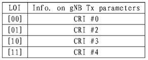
- FIG. 6 is a schematic diagram of correspondence between LOI and related signal identifiers in the case of uplink and downlink beam joint management in the embodiment of the present application;
- FIG. 7 is a schematic flowchart of an implementation manner in which a UE receives an indication from a base station to perform a control channel measurement and applies a quasi-homogeneous relationship according to an embodiment of the present application;
- FIG. 8( a ) is a schematic diagram of an implementation manner of a control channel related QCL configuration information sent by a base station to a UE according to an embodiment of the present application;
- FIG. 8(b) is a schematic diagram of another implementation manner of the control channel-related QCL configuration information sent by the base station to the UE in the embodiment of the present application;
- 9(a) is a schematic diagram of a type of control information sent by a base station to UE1 when UE1 and UE2 are in the same panel in the embodiment of the present application;
- FIG. 9(b) is a schematic diagram of another type of control information sent by the base station to the UE1 when the UE1 and the UE2 are in the same panel in the embodiment of the present application;
- FIG. 10 is a schematic diagram of a time-frequency resource allocation according to an embodiment of the present application.
- FIG. 11 is a schematic flowchart of an implementation manner in which a UE receives an indication from a base station to perform a data channel measurement to apply a quasi-homogeneous relationship according to an embodiment of the present disclosure
- FIG. 12(a) is a schematic diagram of an implementation manner of data channel-related QCL configuration information sent by a base station to a UE in an embodiment of the present application;
- FIG. 12(b) is a schematic diagram of another implementation manner of the data channel-related QCL configuration information sent by the base station to the UE in the embodiment of the present application;
- FIG. 13(a) is a schematic diagram of time-frequency resource allocation when the base station 1 sends a data channel to the UE1 in the embodiment of the present application;
- FIG. 13(b) is a schematic diagram of time-frequency resource allocation when the base station 1 sends a data channel to the UE1 in the embodiment of the present application;
- FIG. 14 is a schematic flowchart of a communication method for determining a resource location parameter of a PUCCH according to an embodiment of the present application
- 15 is a schematic flowchart of another communication method for determining a resource location parameter of a PUCCH according to an embodiment of the present application
- FIG. 16 is a schematic structural diagram of a terminal device according to an embodiment of the present application.
- FIG. 17 is a schematic structural diagram of a base station according to an embodiment of the present application.
- the terminal device in the present application is a device having a wireless communication function, and may be a handheld device having a wireless communication function, an in-vehicle device, a wearable device, a computing device, or other processing device connected to a wireless modem.
- Terminal devices in different networks may be called different names, such as: user equipment, access terminals, subscriber units, subscriber stations, mobile stations, mobile stations, remote stations, remote terminals, mobile devices, user terminals, terminals, wireless communications.
- Device, user agent or user device cellular phone, cordless phone, Session Initiation Protocol (SIP) phone, Wireless Local Loop (WLL) station, Personal Digital Assistant (PDA), Terminal equipment in a 5G network or a future evolution network.
- SIP Session Initiation Protocol
- WLL Wireless Local Loop
- PDA Personal Digital Assistant
- the base station in this application may also be referred to as a base station device, and is a device deployed in a wireless access network to provide wireless communication functions, and may be Global System of Mobile communication (GSM) or code division multiple access.
- GSM Global System of Mobile communication
- BTS Base Transceiver Station
- CDMA Code Division Multiple Access
- NodeB, NB for short base station
- WCDMA Wideband Code Divided Multiple Access
- Evoltial Node B, eNB or eNodeB evolved base station
- LTE Long Term Evolution
- a relay station or an access point a transmission node or a transmission and reception point in the NR system (transmission reception) Point, TRP or TP) or next generation Node B (gNB), Wireless-Fidelity (Wi-Fi) site, wireless backhaul node, small station, micro station, or future fifth generation mobile
- Wi-Fi Wireless-Fidelity
- a quasi-coordinate relationship is used to indicate that one or more identical or similar communication features are between multiple resources.
- multiple resources with quasi-homogeneous relationships the same or similar communication configurations can be employed.
- Large-scale features can include: delay spread, average delay, Doppler spread, Doppler shift, average gain, transmit/receive channel correlation, receive angle of arrival, spatial correlation of receiver antenna, primary angle of arrival (Angel -of-Arrival, AoA), average angle of arrival, extension of AoA, etc.
- the quasi-co-located indication is used to indicate whether the at least two sets of antenna ports have a quasi-homologous relationship: the quasi-co-located indication is used to indicate whether the channel state information reference signals sent by the at least two groups of antenna ports are from the same transmission point, Or the quasi-co-located indication is used to indicate whether the channel state information reference signals sent by the at least two groups of antenna ports are from the same beam group.
- the quasi-homolocation hypothesis is based on the assumption that there is a QCL relationship between the two ports.
- the configuration and indication of the quasi-homolocation hypothesis can be used to assist the receiver in receiving and demodulating the signal.
- the receiving end can confirm that the A port and the B port have a QCL relationship, that is, the large-scale parameter of the signal measured on the A port can be used for signal measurement and demodulation on the B port.
- Airspace quasi-homolocation is a type of QCL.
- the large-scale characteristics of the channel in which one port transmits one symbol can be inferred from the large-scale characteristics of the channel through which one symbol transmits one symbol.
- Large-scale characteristics may include: transmit/receive channel correlation, receive angle of arrival, spatial correlation of receiver antennas, Angel-of-Arrival (AoA), average angle of arrival, extension of AoA, and so on.
- the corresponding beam directions of the two antenna ports are spatially uniform.
- the receiving end if the two antenna ports are spatially quasi-co-located, it means that the receiving end can receive the signals sent by the two antenna ports in the same beam direction.
- the beam can be a wide beam, or a narrow beam, or other type of beam.
- the beamforming technique can be beamforming techniques or other technical means.
- the beamforming technology can be specifically digital beamforming technology, analog beamforming technology, and hybrid digital/analog beamforming technology. Different beams can be considered as different resources. The same information or different information can be transmitted through different beams. Alternatively, multiple beams having the same or similar communication characteristics can be considered as one beam.
- One beam may include one or more antenna ports for transmitting a data channel, a control channel, a sounding signal, etc., for example, the transmitting beam may be a signal intensity distribution formed in different directions of the space after the signal is transmitted through the antenna.
- the receive beam may refer to a signal strength distribution of wireless signals received from the antenna in different directions in space.
- One or more antenna ports forming one beam can also be considered as one antenna port set.
- the beam can also be a spatial filter or a spatial parameter.
- the information of the beam can be identified by the index information.
- the index information may be configured to correspond to a resource identifier of the UE.
- the index information may correspond to an ID or a resource of a channel status information reference signal (CSI-RS).
- the index information may also be index information of a signal or channel display or implicit bearer carried by the beam, for example, the index information may be a synchronization signal sent by a beam or a broadcast channel indicating the beam. Index information.
- the identifier of the information of the beam includes an absolute index of the beam, a relative index of the beam, a logical index of the beam, an index of the antenna port corresponding to the beam, an index of the antenna port group corresponding to the beam, and a downlink synchronization signal block.
- the beam pair may include a transmit beam at the transmitting end and a receive beam at the receiving end, or also referred to as an uplink beam or a downlink beam.
- the beam pair may include a gNB Tx beam transmission beam or a UE Rx parameter reception beam, or a UE Tx beam transmission beam or a gNB Rx parameter reception beam, where the transmission beam may also be understood as a transmission beam.
- the correspondence between the reference signal and the antenna port can be as follows:
- M, N, W, X and Y respectively represent the maximum number of ports of various reference signals. It should be noted that the corresponding relationship between the reference signal and the antenna port is only an exemplary description, and other specific relationships may be used in the specific implementation.
- the antenna ports of different types of RSs may be the same, for example, the port D1 of the DMRS may be the same as the port S0 of the synchronization signal.
- the maximum number of different types of antenna ports is not determined. Possibly, the maximum number of ports for a CSI-RS may be 32, and the maximum number of ports for a DMRS may be 12.
- a communication resource may also be simply referred to as a resource.
- Communication resources can be used to transmit signals.
- the types of communication resources can be spatial resources, time domain resources, and frequency domain resources.
- the types of communication resources may be beams, ports, and the like.
- a collection of different kinds of communication resources is also a communication resource.
- time-frequency resources including time domain resources and frequency domain resources
- a combination of beams and ports is also a communication resource.
- the PDCCH transmission uses different aggregation levels (AL).
- the aggregation level refers to how many CCEs a certain PDCCH carries.
- the aggregation level can be 1, 2, 4 or 8.
- first and second in this application are used for descriptive purposes only, and are not to be construed as indicating or implying a relative importance or implicitly indicating the number of technical features indicated. Thus, features defining “first” and “second” may include one or more of the features either explicitly or implicitly.
- the transmission of the channel is in units of radio frames, and one radio frame includes 10 subframes, each subframe has a length of 1 millisecond (ms), and each subframe includes two subframes. Slot, each slot is 0.5ms. The number of symbols included in each slot is related to the length of the CP (cyclic prefix) in the subframe. If the CP is a normal (normal) CP, each slot includes 7 symbols, and each subframe is composed of 14 symbols. For example, each subframe has a sequence number of #0, #1, #2, #3, #4, respectively. , #5, #6, #7, #8, #9, #10, #11, #12, #13 symbol composition.
- each s lot includes 6 symbols, and each subframe is composed of 12 symbols, for example, each subframe has a sequence number of #0, #1, #2, #3, #4, respectively. Symbolic composition of #5, #6, #7, #8, #9, #10, #11.
- the downlink symbols are called orthogonal frequency division multiplexing (OFDM) symbols.
- a resource element (RE) is the smallest unit in the time-frequency domain, and is uniquely identified by an index pair (k, l), where k is a subcarrier index and l is a symbol index.
- the fixed LTE protocol specifies the QCL relationship between antenna ports for various parameters. Depending on the mode of transmission, the UE can make QCL assumptions between different ports.
- the port mentioned in the embodiment of the present application is an antenna port, unless otherwise specified.
- transmission mode 8-10 The UE can assume that the antenna port 7-14 is related to delay spread, Doppler spread, Doppler shift, average gain, average delay, and five parameters QCL; transmission mode 1- 9: Antenna port 0-3, 5, 7-30 is about the four parameters QCL of Doppler shift, Doppler spread, delay spread, average delay; transmission mode 10: for antenna port 7-14
- Two types of QCL relationships can be configured by high-level signaling qcl-Operation, where a QCL relationship is: UE can assume that antenna ports 0-3, 7-30 are related to Doppler shift, Doppler Expansion, delay spread, average delay, the four parameters of the QCL; another QCL relationship is: the UE can assume the CSI-RS antenna indicated by the high layer signaling qcl-CSI-RS-ConfigNZPId-r11 in the antenna ports 15-30 The port and antenna port 7-14 are related to the four parameters QCL of Doppler shift, Doppler spread, delay spread, and average delay.
- the above transmission mode is that the base station notifies the UE through high layer signaling.
- the parameter set of the high layer signaling configuration can provide a time-frequency mapping pattern of various reference signals.
- the data channel PDSCH cannot be mapped any more.
- the QCL hypothesis information is used in the process of rate matching, antenna port mapping and time-frequency resource mapping on the base station side, inverse mapping on the UE side, and inverse rate matching.
- the reference signal is mainly used to estimate channel parameters, thereby assisting in demodulation of the physical channel.
- the downlink communication signal in the LTE includes a synchronization signal (SS), a cell-specific reference signal (CRS), a CSI-RS, a DMRS, and the like.
- the SS is further subdivided into a primary synchronization signal (primary SS, PSS) and a secondary synchronization signal (secondary SS, SSS).
- the downlink physical channel in the LTE includes, but is not limited to, a physical broadcast channel (PBCH), a physical downlink control channel (PDCCH), a physical downlink shared channel (PDSCH), and a PDSCH. It is called the downlink data channel.
- PBCH physical broadcast channel
- PDCCH physical downlink control channel
- PDSCH physical downlink shared channel
- PDSCH physical downlink shared channel
- the antenna ports of various reference signals and physical channels in LTE have corresponding rules.
- the base station uses one antenna port for communication.
- the base station uses the antenna port 0 to transmit the SS and the PBCH, and also uses the antenna port 0 to transmit the CRS.
- the PDCCH is transmitted in the same manner as the PBCH, and the PDCCH uses the CRS for channel estimation and demodulation.
- the demodulation of the PDSCH also uses the CRS, that is, the transmission of the PDSCH is also based on the antenna port 0.
- the PDSCH is demodulated using DMRS, that is, the PDSCH is transmitted using the port used for DMRS transmission.
- the technical solution for QCL in LTE cannot adapt to the needs of NR. More specifically, in addition to beam-based transmission, there is no longer CRS transmission in NR, PDCCH demodulation is no longer based on CRS, and there is no longer the same transmission mode as LTE in NR, which affects QCL in LTE.
- the technical solution is applicable in NR.
- Embodiments of the present application provide a communication method and apparatus to implement configuration, indication, and use of a QCL in an NR.
- the UE In mobile communications, the UE typically attempts to establish a connection with the base station before communicating with a certain base station. That is, the base station transmits signals through beams in different directions. If the UE enters the coverage of the base station, the UE attempts to access the base station by receiving a signal in a certain beam direction or a signal in a certain beam direction, that is, sending the base station through the receiving base station. The signal attempts to establish a communication connection with the base station.
- the manner in which the base station transmits signals and the UE receives signals includes, but is not limited to, the following two modes.
- Mode A The base station sweeps its N beam directions in n milliseconds; the UE attempts to receive in its own receive beam direction 1 with a time window of n milliseconds or more than n milliseconds; afterwards, the UE attempts to receive in the receive beam direction 2, Cycling in sequence; after the UE scans its own N receive beams, it selects a stronger receive beam and a corresponding transmit beam for subsequent access procedures.
- Mode B By setting a threshold in advance, a subsequent access procedure may be performed on the corresponding beam as long as the received energy of the UE is greater than the threshold.
- the base station sends SS blocks to different beam directions at different times, and the UE can receive the SS block sent by the base station in a certain beam direction.
- the base station may send multiple SS blocks from one port to different beam directions.
- the SS block is a type of synchronization signal, and the UE attempts to access the base station by receiving the SS block sent by the base station.
- the base station sends an SS block to the UE.
- FIG. 1 is a schematic diagram of a basic process of an interaction process between a base station and a UE. It can be understood that, in the specific implementation, there are other interaction processes between the base station and the UE, and the embodiment of the present application only shows some steps and processes for the convenience of description. For example, after step 100, the UE also initiates random access, and a process of random access between the UE and the base station is also performed. These processes are not shown in FIG. 1.
- the base station After the UE accesses the network, the base station sends configuration information to the UE to indicate the reference signal that the UE needs to measure (step 102). After receiving the configuration information sent by the base station, the UE performs measurement of the signal according to the indication of the base station (step 103). Through this process, the base station can know the channel state with the UE, such as the beam quality between the base station and the UE, and the like.
- the base station After the UE completes the channel measurement, the base station sends the downlink control channel information (step 104) and the downlink data channel information (step 105) to the UE to implement downlink control information and data information transmission. Correspondingly, the UE sends an uplink signal, an uplink data channel or an uplink control channel to the base station in step 106.
- the base station when transmitting the related information to the UE, the base station may indicate the UE's quasi-homogenous relationship.
- the UE acquires related information according to the quasi-homologous relationship indicated by the base station. For example, according to the quasi-homogeneous relationship between the port for transmitting the measurement signal indicated by the base station and the port for transmitting other signals, the UE may acquire the average gain of the other signals, and use the obtained average gain as the measurement signal. Average gain.
- the implementation manner of applying the quasi-homologous relationship to the channel measurement by the UE receiving the indication of the base station in the foregoing step 102 is as follows.
- the UE receives the implementation manner of applying the quasi-homologous relationship of the downlink control channel information sent by the base station, and the UE receives the base station in step 105.
- a method for implementing the configuration, indication, and use of the QCL in the NR provided by the embodiment of the present application is described. It can be understood that for other processing methods that need to perform QCL, it can be implemented by referring to these implementation manners, and only corresponding adjustments can be made to the corresponding parameters.
- the channel measurement is applied to the implementation of the quasi-homologous relationship, as shown in FIG. 2 .
- the implementation process of the method shown in Figure 2 includes:
- Step 200 The UE receives an SS block sent by the base station.
- the base station transmits SS blocks to different beam directions at different times through one port.
- the UE attempts to receive the SS block sent by the base station within the coverage of the base station. That is, the base station transmits the SS block in a beam scanning manner, and the UE receives the SS block sent by the base station in a certain beam direction. Moreover, after receiving the SS block sent by the base station, the UE measures the average gain of the received SS block.
- the base station sends an SS block through a port as an example for description. For the manner in which the base station sends other synchronization signals, reference may be made to the implementation manner of sending the SS block.
- the SS block includes SSS, PSS, and PBCH.
- Step 202 The UE receives a measurement indication sent by the base station, where the measurement indication includes measurement information, beam information, and quasi-homogenous relationship information.
- the measurement information includes signal information that needs to be measured.
- the measurement information further includes information such as a parameter to be measured (for example, RSRP or CQI, etc.) and a feedback manner of the measured quantity.
- a parameter to be measured for example, RSRP or CQI, etc.
- the measured quantity is a value measured after the parameter to be measured, or a value or quantity obtained after measuring the parameter to be measured.
- the measured amount may also be referred to as a measurement result.
- the beam information is information of a beam that receives the signal that needs to be measured.
- the quasi-co-location relationship information is information for transmitting a quasi-homogeneous relationship between a port of the signal that needs to be measured and another port.
- the base station may separately transmit measurement information, beam information, and quasi-homogenous relationship information included in the measurement indication by using different signaling.
- These signalings include, but are not limited to, RRC signaling, MAC-CE signaling, or DCI.
- Step 204 The UE acquires the measurement quantity according to the indication of the base station.
- the UE receives a signal that needs to be measured from the receiving beam according to the measurement indication sent by the base station, and acquires a measurement quantity of the signal that needs to be measured according to the quasi-homologous relationship information.
- the signal that needs to be measured is a CSI-RS signal, and the average gain of the CSI-RS signal needs to be measured as an example.
- the implementation manner shown in FIG. 2 is described in detail. It can be understood that the implementation of channel measurement for other signals (such as PDCCH or DMRS signal of PDSCH) can be implemented by referring to the implementation of the following CSI-RS signal.
- the base station may send a measurement indication to the UE by using radio resource control (RRC) signaling.
- the measurement information included in the measurement indication may be a CSI-RS resource, where the CSI-RS resource includes, but is not limited to, a resource number of the CSI-RS signal, a time when the CSI-RS signal is sent, and the sending The frequency of the CSI-RS signal, the period of signal transmission (periodic or aperiodic), and the port that transmits the CSI-RS signal.
- the information is configured by the base station and sent to the UE, and the UE receives the CSI-RS signal sent by the base station according to the indication of the information.
- one CSI-RS resource may be represented by a CSI-RS resource ID.
- the CSI-RS resource may further include a CSI-RS resource setting or a CSI-RS reporting setting.
- the CSI-RS resource sett ing includes one or more CSI-RS resource sets, and each CSI-RS resource set further includes one or more CSI-resources.
- the UE when the base station sends the CSI-RS signal according to the foregoing CSI-RS resource, the UE can receive the corresponding CSI-RS signal. For example, if the CSI-RS signal to be measured is configured on the (k, l) time-frequency resource of the X subframe and two ports are used, then the base station will be on the (k, l) time-frequency resource of the X subframe. Configure and send to the UE.
- the beam information refers to information that the UE receives a beam of a CSI-RS signal that needs to be measured.
- the beam information may include at least one of the following information: an index of a beam, an index of an antenna port corresponding to a beam, an index of a reference signal corresponding to a beam, a time index of a downlink synchronization signal block, or a beam pair link (Beam pair link, BPL) information.
- BPL beam pair link
- the UE may receive the information about the beam that receives the CSI-RS signal sent by the base station by using the RRC signaling, and may also receive the beam direction of the CSI-RS signal sent by the base station by using the MAC-CE signaling or the DCI. Information.
- 3(a) and 3(b) will be described below as an example of a base station configuration measurement indication and a manner in which the UE acquires a measurement amount.
- the QCL type 3 indicates beam information (for example, an SS block time index), and the UE learns, according to the beam information, that there is a spatial QCL relationship between the antenna port transmitting the CSI-RS signal and the SS port.
- beam information for example, an SS block time index
- the UE Since the SS block is sent by the base station from the SS port, when the UE receives the configuration information about the QCL type 1 sent by the base station, the UE can learn to send the CSI according to the configuration information of the SS port and the CSI-RS resource indicated by the QCL type 1. There is a quasi-homogeneous relationship with respect to the average gain between the port of the CSI-RS signal corresponding to the RS resource and the SS port.
- each of the multiple ports has a QCL relationship with an average gain of the SS port.
- the CSI-RS resource in FIG. 3(a) may be represented by a CSI-RS resource number.
- the CSI-RS resource in FIG. 3(a) may be represented by a CSI-RS port number.
- one CSI-RS resource includes two ports: port 1 and port 2.
- the base station uses the port identifier to represent the CSI-RS resource when configuring QCL type 1. For a port that has an average gain with the SS port, the base station configures QCL Type 1 and sends it to the UE. In this way, when the UE receives the configuration information about the QCL type 1 sent by the base station, it can be known which port and the SS port have a QCL relationship with respect to the average gain.
- the manner in which the base station sends the QCL type 1 may be: adding a field in the signaling (for example, RRC signaling) sent to the UE, where the field indicates that there is an average between the SS port and the CSI-RS resource.
- the manner in which the base station sends the QCL type 3 may be: adding a field in the signaling (for example, MAC-CE signaling) sent to the UE, where the field indicates that the UE receives the beam of the CSI-RS resource, and sends the CSI-RS resource.
- the UE After receiving the configuration information about the QCL type 1 and the QCL type 3 sent by the base station, the UE can learn the beam information of the CSI-RS resource that needs to be measured, and the related QCL relationship information.
- the UE may receive the CSI-RS signal from the beam indicated by the QCL type 3, and receive the QCL relationship with respect to the average gain based on the SS port indicated by the QCL type 1 and the QCL relationship of the CSI-RS resource with respect to the average gain, and will receive from the beam direction indicated by the QCL type 3
- the average gain of the SS block is taken as the average gain of the CSI-RS signal that needs to be measured.
- the manner in which the UE obtains the average gain of the CSI-RS signal according to the configuration information indicated by the QCL type 1 and the QCL type 3, includes but is not limited to the following manners:
- Manner 1 The UE directly measures the average gain of the SS block received in the beam direction indicated by the QCL type 3 as the average gain of the CSI-RS signal. For example, the value of the L1SS block RSRP obtained by measuring the SS block in the beam direction indicated by the QCL type 3 is taken as the value of the L1RSRP of the CSI-RS signal, and the RSRP of the CSI-RS signal is no longer measured.
- Manner 2 The UE performs average processing or joint filtering on the average gain of the SS block received in the measured beam direction indicated by the measured QCL type 3, and obtains the average gain of the final CSI-RS signal. For example, the UE measures the received CSI-RS signal in the beam direction indicated by the QCL type 3 to obtain the L1 CSI-RS RSRP, and then compares the value of the L1 CSI-RS RSRP with the measured SS block obtained by the L1SS block RSRP. The values are averaged or combined filtered to obtain a further accurate and stable L1RSRP value.
- Manner 3 When the configuration information sent by the base station to the UE further includes the measured time window, the UE will measure the obtained L1CSI-RS RSRP value and the measured SS block obtained by the SS block in the measurement time window. The RSRP values are averaged or jointly filtered to obtain a further accurate and stable L1RSRP value.
- the CSI-RS resource identifier, the port number, and the like may be replaced by a low overhead indicator (LOI).
- LOI low overhead indicator
- the LOI is only a temporary name indicated by a beam, and it can also be any identifier used to represent a beam.
- the indication is sent to the UE through the LOI, and the base station needs to establish a correspondence between the LOI and the transmit beam, and the UE also establishes a correspondence between the LOI and the receive beam and the corresponding transmit beam of the base station.
- the following takes the CSI-RS signal as an example to describe the manner in which the base station and/or the UE establishes and maintains the correspondence between the LOI and the beam from the downlink transmission beam, the uplink transmission beam, and the UE support beam reciprocity. It can be understood that LOI related configuration and management of signals such as SS block can also be implemented by referring to the CSI-RS signal, and details are not described herein.
- the beam reciprocity refers to that the device can ensure that the direction of the receiving beam and the direction of the transmitting beam are consistent.
- the UE supports beam reciprocity, which means that the UE can ensure that the direction of the receive beam and the direction of the transmit beam are consistent.
- beam reciprocity the uplink beam and the downlink beam can be uniformly managed; in the absence of beam reciprocity, the management of the uplink transmit beam and the downlink transmit beam are performed separately.
- the UE maintains the correspondence between the receiving beam of one UE, the transmitting beam of the base station, and the QCL according to the indication of the base station.
- CRI#0 represents a downlink signal identifier, and the downlink signal identifier is also a transmit beam of the base station;
- Rx parameter#0 represents a spatial parameter, and the airspace parameter is also a receive beam of the UE.
- the LOI represents CRI#0 with fewer bits.
- SS block t ime index #0 may be used instead of CRI #0 in FIG. 4(a).
- the airspace parameter may also refer to the weight of the antenna structure or the radio frequency link.
- the base station then instructs the UE to perform measurements of other CSI-RS signals. For example, the base station instructs the UE to measure CSI-RS signals in different transmit beam directions and feed back L1-RSRP corresponding to each CRI. These beams of different beam directions are represented by CRI #1, CRI #2, CRI #3, and CRI #4.
- the base station may notify the UE that the CRI #1, CRI #2, and CRI# to be measured are required.
- the UE receives the beams CRI #1, CRI #2, CRI #3, and CRI #4 transmitted by the base station in the same receiving direction as CRI #0 according to the notification from the base station.
- the base station instructs the UE to scan the base station for the transmit beams of CRI #1, CRI #2, CRI #3, and CRI #4 in the receive beam direction corresponding to Rx parameter #0 by implicit indication.
- the UE performs measurement and feedback according to the indication of the base station. That is, the L1-RSRP of the downlink beam (ie, the RS corresponding to each CRI) is fed back.
- the base station associates the LOI and the CRI according to the feedback of the UE, obtains a correspondence relationship as shown in FIG. 4(b), and sends the corresponding relationship to the UE.
- the base station may directly configure the correspondence between the LOI and the CRI, and directly send the corresponding relationship between the LOI and the CRI to the UE.
- the UE may update the correspondence maintained by itself.
- the corresponding relationship after the UE is updated may be that the content of the corresponding relationship in FIG. 4(b) is added to the table shown in FIG. 4(a) maintained by the UE, and the corresponding relationship as shown in FIG. 4(c) is obtained.
- the spatial domain parameter of the UE may be the measured amount after measuring the CSI-RS signal represented by CRI #0.
- the base station or the UE may perform update and maintenance according to the foregoing manner.
- the base station may also send the updated correspondence to the UE after the update.
- the CRI identifiers in the foregoing FIG. 4(a), FIG. 4(b), and FIG. 4(c) may also be identified by a port number, which is not specifically limited in this embodiment.
- the mapping relationship between a LOI and a downlink signal identifier may be used, or may be one LOI and multiple downlinks.
- the base station and the UE may update FIG. 4(b) and FIG. 4(c) through predefined rules.
- the predefined rules include always having the LOI directly associated with the size of the RSRP. For example, LOI[00] always corresponds to the CRI of the largest RSRP.
- the base station and the UE can communicate using the default beam direction through predefined rules.
- the predefined rules include the beam of the strongest RSRP that always uses the last UE feedback, and the UE accesses the wide beam used by the network.
- the UE maintains the correspondence between the transmit beam of one UE, the receive beam of the base station, and the LOI according to the indication of the base station.
- SRI#0 represents an uplink signal identifier
- the uplink signal identifier is also a receive beam of the base station
- Tx parameter#0 represents a spatial domain parameter
- the airspace parameter is also a transmit beam of the UE
- the LOI passes less.
- the bits represent SRI#0.
- PRACH may be used instead of SRI#0 in FIG. 5(a).
- the base station instructs the UE to transmit an SRS signal, and the base station measures the L1-RSRP of the transmit beam corresponding to each SRS signal.
- the base station may further notify the UE of the beam directions of the SRI #1, SRI #2, SRI #3, and SRI #4 that need to be measured, and have a spatial QCL relationship with the beam direction of the SRI #0.
- the UE may also determine that the beams of SRI #1, SRI #2, SRI #3, and SRI #4 need to be transmitted.
- the base station may configure one or more SRS resource groups for the UE.
- One SRS resource group may include SRS resources corresponding to, for example, ⁇ SRI#1, SRI#2, SRI#3, and SRI#4 ⁇ .
- One or more resource groups can be used for upstream beam management.
- the base station may configure the UE to transmit the SRS on all SRS resources within one or more SRS resource groups using the same transmission power.
- the transmission power refers to the power of the SRS transmitted, for example, as an EPRE (Energy per resource element).
- the UE may request the configuration of the SRS resource group or the SRS resource from the base station.
- the UE may perform the beam switching capability of the UE, and the base station configures the SRS transmission time-frequency resource and/or the beam direction that meets the UE capability according to the request of the received UE, and sends the signal to the UE.
- the base station establishes a correspondence between the LOI and the receiving beam after the measurement and sends the corresponding relationship to the UE, and the corresponding relationship is as shown in FIG. 5(b).
- the base station may directly configure the mapping between the LOI and the SRI, and directly send the corresponding relationship between the LOI and the SRI to the UE.
- the UE may update the received correspondence to the corresponding relationship maintained by the UE.
- the corresponding relationship after the UE is updated may be as shown in FIG. 5(c).
- the spatial domain parameter of the UE that is, Tx parameter #0 is the measured amount after measuring the SRS signal represented by SRI #0.
- the base station or the UE may perform update and maintenance according to the foregoing process. After updating, the base station may send the updated correspondence to the UE.
- the SRI identifiers in the foregoing FIG. 5(a), FIG. 5(b), and FIG. 5(c) may also be identified by a port number, which is not specifically limited in this embodiment.
- the UE supports beam reciprocity
- the UE can ensure that the receive beam direction and the transmit beam direction are consistent.
- ⁇ CRI#0, SRI#0 ⁇ can be configured to have a spatial QCL relationship
- ⁇ CRI#2, SRI#2 ⁇ , ⁇ CRI#3, SRI#3 ⁇ , and ⁇ CRI#4, SRI#4 ⁇ Each pair can also be configured to have a spatial QCL relationship.
- the mapping relationship established by the downlink beam management described above, for example, FIG. 4(b) or FIG. 4(c) can be used for uplink beam indication.
- the mapping relationship established by the foregoing uplink beam management such as FIG. 5(b) or FIG. 5(c) can also be used for downlink beam indication.
- the uplink and downlink beam management may be jointly performed, and the base station and/or the UE may establish a mapping relationship between the LOI, the CRI/SRI, the base station Tx/Rx beam, and the UE side Rx/Tx beam.
- An implementation of this mapping relationship can be as shown in FIG. 6.
- the base station When the base station sends a beam indication to the UE through the LOI, the downlink beam is managed by the UE, that is, the correspondence shown in FIG. 4(c) is maintained; and the uplink beam is also managed, that is, FIG. 5(c) is maintained.
- the UE also supports beam reciprocity, if the UE receives the information sent by the base station using the LOI as the beam indication, if the LOI has only 2 bits of information, the UE cannot determine to use FIG. 4(c).
- the correspondence shown is also the correspondence shown in Fig. 5(c).
- the beam indication indicated by the UE in the above step 202 based on the QCL Type 3 indication by the UE may cause an error because the transmission beam or the reception beam is not clearly indicated.
- the reason is that the LOI is represented by bits and does not clearly indicate whether it is a transmit beam or a receive beam.
- the UE may determine the beam direction indicated by the base station in the following two manners:
- Manner 1 When the UE does not support beam reciprocity, the UE determines a specific beam according to the beam information indicated by the QCL type 3. For example, the manner of indicating beam information in FIG. 3(a).
- the base station notifies the UE to transmit the beam information of the CSI-RS signal through an indicator (ie, LOI).
- an indicator ie, LOI
- the UE can learn from the LOI that the antenna port that sends the CSI-RS signal has a spatial QCL relationship with the antenna port of a previously measured reference signal.
- the UE When the UE receives the signaling including the QCL type 3 sent by the base station to control the signaling of the downlink transmission, the UE can learn the downlink LOI according to the LOI carried in the signaling of the downlink transmission.
- the UE determines the information of the beam receiving the CSI-RS signal according to the correspondence maintained in FIG. 4(c). After receiving the LOI sent by the base station, the UE can learn from the LOI that the antenna port that sends the CSI-RS signal has a spatial QCL relationship with the antenna port of a previously measured reference signal.
- the base station indicates to the UE that the LOI of the QCL type 3 is 01 by controlling the signaling of the downlink transmission, and the UE can learn that the beam receiving the CSI-RS signal is the same as the previous received CRI#2 in combination with the corresponding relationship in FIG. 4(c).
- the receive beam corresponding to the downlink beam At the same time, the UE can learn from the LOI that the port receiving the CSI-RS signal has a spatial QCL relationship with the port of the receiving beam corresponding to the downlink beam receiving the CRI #2.
- Manner 2 When the UE supports beam reciprocity, the UE indicates that the content used in the beam indication of the uplink beam direction is the indication of the downlink beam pair according to the QCL type 3, or the content used in the beam indication of the downlink beam direction is the uplink beam pair. Instructions.
- the UE indicates that the content used in the beam indication of the uplink beam direction is an indication of a downlink beam pair, or the content used in the beam indication of the downlink beam direction is an indication of an uplink beam pair, which is based on an advance.
- the base station may pre-configure the UE to determine the specifically indicated beam direction according to the configured manner when receiving the indication of the QCL type 3.
- the information configured by the base station in the QCL type 3 includes ⁇ CRI resources, SRS resources ⁇ and beam indication information (ie, LOI).
- the UE receives the indication of the QCL type 3 by the base station by controlling the signaling of the downlink transmission, the UE determines that the LOI is the downlink LOI according to the preselected configuration.
- the UE acquires the CRI# corresponding to the received LOI by using the corresponding relationship of FIG. 4(c) according to the received LOI, and determines the CRI according to the spatial QCL relationship between the CRI resource and the SRS resource in FIG. 3(b). # Corresponding SRI#, and determine the transmit beam based on the acquired SRI#.
- the UE determines that the LOI is the uplink LOI according to the preselected configuration.
- the UE acquires the SRI# corresponding to the received LOI by using the corresponding relationship of FIG. 5(c) according to the received LOI, and determines the SRI according to the spatial QCL relationship between the CRI resource and the SRS resource in FIG. 3(b). # Corresponding CRI#, and determine the receiving beam according to the acquired CRI#.
- the sending, by the base station, the QCL configuration information to the UE may further indicate that there is a quasi-homogenous relationship between the path loss of the downlink transmission and the path loss of the uplink insertion loss.
- the base station indicates to the UE through the QCL type 1 that there is a quasi-homogenous relationship between the CSI-RS resource and the SRS resource with respect to the path loss.
- Figure 3 (c) shows the configuration and indication mode of the quasi-homologous relationship between the path loss of the downlink transmission and the path loss of the uplink transmission, which can be compared with the SS port and CSI-RS in Figure 3(a) and Figure 3(b) above.
- the configuration and indication of the quasi-homologous relationship between resources are similar and will not be described again.
- the configuration and indication of the QCL type 3 in FIG. 3(c) may be similar to the configuration and indication of the QCL type 3 in FIG. 3(a) and FIG. 3(b), and will not be described again.
- the UE may obtain a path loss of the CSI-RS signal according to a quasi-homologous relationship between the path loss of the downlink transmission and the path loss of the uplink transmission in FIG. 3(c) and the beam information indicated by the QCL type 3 (path loss). ).
- the path loss can be obtained by subtracting the received power from the transmission power.
- the UE may estimate the path loss of the uplink transmission by measuring or acquiring the average gain of the CSI-RS.
- the QCL type 1 of FIG. 3(c) may also be configured to have a quasi-homogeneous relationship with respect to path loss between other downlink signals (eg, sync signal blocks) and the SRS.
- other downlink signals eg, sync signal blocks
- the QCL type 1 in FIG. 3(c) may also be configured to have a quasi-homogeneous relationship with respect to path loss between a set of CSI-RS resources and a set of SRS resources.
- the base station may also jointly estimate the path loss between the base station and the UE by measuring the average gain of the SRS and the average gain of the CSI-RS fed back by the UE.
- the base station may further notify the UE to measure a difference between the CSI-RS average gain estimation path loss and the measured SRS average gain estimation path loss.
- the contents in FIG. 3(a), FIG. 3(b) and FIG. 3(c) are optional, and the base station performs correlation when there is a relevant type of QCL hypothesis between the two ports. Configuration. When there is no relevant type of QCL assumption between two ports, there should be no QCL relationship by default, and the channel parameters of each port need to be measured independently.
- the base station configures the QCL about the average gain
- the QCL type 3 in FIG. 3(a), FIG. 3(b), and FIG. 3(c) is also optional. In specific implementation, the base station may only be configured.
- the content of the QCL type 1 is sent to the UE; after receiving the indication of the QCL type 1 transmitted by the base station, the UE can learn the QCL relationship about the average gain.
- the embodiment of the present application does not limit the number of bytes used in FIG. 3(a), FIG. 3(b), and FIG. 3(c) for indicating QCL type 1.
- 3(a), 3(b) and 3(c) are used to indicate that the byte about QCL type 1 can be 2 bytes, 3 bytes, or multiple bytes.
- the embodiments of the present application are not specifically limited.
- control channel related QCL in NR system
- the implementation manner of applying the quasi-homologous relationship to the control channel measurement of the UE receiving the indication of the base station may be as shown in FIG. 7, and the implementation process includes:
- Step 300 The UE receives a measurement indication sent by the base station, where the measurement indication includes control channel information, beam information, and quasi-homogenous relationship information.
- the control channel information may be a port for transmitting a control channel DMRS signal, and the control channel DMRS signal is a DMRS for control channel demodulation.
- the port for transmitting the control channel DMRS signal and the RE for the control channel DMRS signal are associated with each other.
- the UE can obtain information such as the time-frequency resource location of the control channel DMRS signal that needs to be measured according to the port.
- the beam information is beam information that the UE receives the control channel information.
- the quasi-homologous relationship information is information of a quasi-homogeneous relationship existing between a port transmitting the control channel DMRS signal and a port transmitting another signal.
- the antenna port of the DMRS signal (PDCCH-DMRS) of the control channel is the port used by the base station to send the PDCCH to the UE.
- the beam information is a beam that the UE receives the PDCCH, and is also direction information of the UE measurement control channel DMRS.
- the beam information includes at least one of the following: an index of a beam, an index of an antenna port corresponding to a beam, an index of a reference signal corresponding to a beam, a time index of a downlink synchronization signal block, or a beam pair connection BPL information.
- the base station may separately send control channel information, beam information, and quasi-homomorphic relationship information to the UE through different signaling.
- These signalings include, but are not limited to, RRC signaling, MAC-CE signaling, or DCI.
- Step 302 The UE acquires the measurement quantity according to the quasi-homologous relationship information sent by the base station.
- the UE receives a signal that needs to be measured from the receiving beam according to the measurement indication sent by the base station, and obtains, according to the quasi-homomorphic relationship information, an average gain, delay spread, and Doppler of the control channel DMRS signal that needs to be measured. Le expansion, Doppler shift, average delay, etc.
- 8(a) and 8(b) will be described below as an example of a base station configuration measurement indication and a manner in which the UE acquires a measurement amount.
- the QCL relationship between the port for transmitting the control channel DMRS signal to be measured and the port for transmitting the CSI-RS signal is described as an example of the average gain, and is required for transmission.
- There is a QCL relationship with respect to the average gain between the port of the control channel DMRS signal on which the measurement is performed and the port transmitting the other signal which can be implemented as shown in Figs. 8(a) and 8(b).
- the CSI-RS resources in FIG. 8(a) and FIG. 8(b) can refer to the descriptions of the CSI-RS resources in FIG. 2, FIG. 3(a) and FIG. 3(b) above.
- the parity information transmitted by the base station to the UE includes QCL type 1, QCL type 2, and QCL type 3.
- the QCL type 1 is used to indicate that there is a quasi-homogeneous relationship with respect to the average gain between the port transmitting the DMRS signal and the port transmitting the CSI-RS resource. That is, each port in the DMRS port group has a quasi-homogeneous relationship with respect to the average gain and the port on which the base station transmits the CSI-RS.
- one DMRS port group includes one or more ports that send DMRS signals.
- the correspondence between each DMRS port group and the port that sends the DMRS signal is as follows:
- DRMS port group 1 D1-D4;
- DRMS port group 2 D5-D8;
- DRMS port group 1-1 D1-D2;
- DRMS port group 1-2 D3-D4;
- DRMS port group 2-1 D5-D6;
- DRMS port group 2-2 D7-D8.
- the QCL type 2 is used to indicate a quasi-homogonal relationship between a port transmitting a control channel DMRS signal and a port transmitting a CSI-RS resource with respect to delay spread, Doppler spread, Doppler shift, average delay, and the like.
- the UE can obtain the port for transmitting the control channel DMRS signal according to the QCL relationship between the port transmitting the control channel DMRS signal and the port transmitting the CSI-RS resource with respect to the average gain.
- the UE may delay the extension of the CSI-RS signal identified by the CSI-RS resource corresponding to the group in which the base station transmits the control channel DMRS signal according to the information indicated by the QCL type 2, Doppler extension, Doppler.
- the frequency shift and the average delay are used as delay spread, Doppler spread, Doppler shift, and average delay of the DMRS signal of the control channel.
- the UE may acquire the control channel DMRS signal and the CSI-RS signal according to the port of the control channel DMRS signal and the packet information of the QCL type 1 with respect to delay spread, Doppler spread, Doppler shift. Quasi-homologous information such as average delay.
- the resources occupied by the base station when sending signaling to the UE can be reduced, and the consumption of signaling resources is saved.
- QCL Type 3 is used to instruct the UE to receive beam information of control information.
- the UE has a spatial QCL relationship between the antenna port that can transmit the control channel DMRS signal and the port that sends the CSI-RS resource according to the received beam information.
- the base station can use an indicator to inform the UE to transmit the receive beam direction.
- the base station needs to send information of the control channel DMRS signal to the UE on the transmit beam corresponding to the receive beam. That is, the transmit beam of the base station corresponds to the receive beam of the UE, and the UE needs to receive the signal of the control channel according to the receive beam indicated by the base station.
- the UE may learn that there is a spatial QCL relationship between the antenna port transmitting the control channel DMRS signal and the port transmitting the CSI-RS resource according to the QCL type 3, and receiving the base station from the receive beam indicated by the QCL type 3 The transmitted control channel DMRS signal. Then, according to the configuration information of the QCL type 1, the UE learns that there is a QCL relationship with respect to the average gain between the port transmitting the control channel DMRS signal and the port transmitting the CSI-RS resource.
- the UE may first determine, according to the configuration information indicated by the QCL type 1, the group in which the port on which the base station transmits the control channel DMRS signal is located, and then use the average gain of the CSI-RS resource corresponding to the group in which the control channel DMRS port is located as the control. The average gain of the channel DMRS signal. Then, the UE learns the port that sends the control channel DMRS signal and sends the CSI according to the information indicated by the QCL type 2 and the QCL relationship between the port transmitting the control channel DMRS signal and the port transmitting the CSI-RS resource. There are QCL relationships between the ports of the RS resources regarding delay spread, Doppler spread, Doppler shift, average delay, and the like.
- the average delay is used as delay spread, Doppler spread, Doppler shift, and average delay of the DMRS signal of the control channel.
- the UE receives the used LOI sent by the base station.
- the information indicating the beam if the LOI has only 2 bits of information, the UE cannot determine whether to use the correspondence shown in FIG. 4(c) or the correspondence shown in FIG. 5(c).
- the UE receives the beam indication indicated by the base station based on the QCL type 3, which may cause an error because the transmission beam or the reception beam is not clearly indicated. The reason is that the LOI is represented by bits and does not clearly indicate whether it is a transmit beam or a receive beam.
- the UE may determine the beam direction indicated by the base station in the following two manners:
- Manner 1 When the UE does not support beam reciprocity, the UE determines a specific beam according to the beam information indicated by the QCL type 3. For example, the manner in which the beam information is indicated in Fig. 8(a).
- the base station notifies the UE to transmit beam information of the control channel DMRS signal through an indicator (ie, LOI).
- an indicator ie, LOI
- the UE can learn from the LOI that the antenna port that sends the control channel DMRS signal has a spatial QCL relationship with the antenna port of a previously measured reference signal.
- the UE When the UE receives the signaling including the QCL type 3 sent by the base station to control the signaling of the downlink transmission, the UE can learn the downlink LOI according to the LOI carried in the signaling of the downlink transmission.
- the UE determines the information of the beam receiving the control channel DMRS signal according to the correspondence maintained in FIG. 4(c).
- the UE After receiving the LOI sent by the base station, the UE can learn from the LOI that the antenna port that sends the control channel DMRS signal has a spatial QCL relationship with the antenna port of a previously measured reference signal.
- the base station indicates to the UE that the LOI of the QCL type 3 is 01 by controlling the signaling of the downlink transmission, and the UE can learn that the beam receiving the control channel DMRS signal is the same as the previous receiving CRI #2, in combination with the corresponding relationship in FIG. 4(c).
- the receive beam corresponding to the downlink beam At the same time, the UE can learn from the LOI that the port receiving the control channel DMRS signal has a spatial QCL relationship with the port of the receiving beam corresponding to the downlink beam receiving the CRI #2.
- Manner 2 When the UE supports beam reciprocity, the UE indicates that the content used in the beam indication of the uplink beam direction is the indication of the downlink beam pair according to the QCL type 3, or the content used in the beam indication of the downlink beam direction is the uplink beam pair. Instructions.
- the UE indicates that the content used in the beam indication of the uplink beam direction is an indication of a downlink beam pair, or the content used in the beam indication of the downlink beam direction is an indication of an uplink beam pair, which is based on an advance.
- the base station may pre-configure the UE to determine the specifically indicated beam direction according to the configured manner when receiving the indication of the QCL type 3.
- the information configured by the base station in the QCL type 3 includes ⁇ CRI resources, SRS resources ⁇ and beam indication information (ie, LOI).
- the UE receives the indication of the QCL type 3 by the base station by controlling the signaling of the downlink transmission, the UE determines that the LOI is the downlink LOI according to the preselected configuration.
- the UE acquires the CRI# corresponding to the received LOI by using the corresponding relationship of FIG. 4(c) according to the received LOI, and determines the CRI according to the spatial QCL relationship between the CRI resource and the SRS resource in FIG. 8(b). # Corresponding SRI#, and determine the transmit beam based on the acquired SRI#.
- the UE determines that the LOI is the uplink LOI according to the preselected configuration.
- the UE acquires the SRI# corresponding to the received LOI by using the corresponding relationship of FIG. 5(c) according to the received LOI, and determines the SRI according to the spatial QCL relationship between the CRI resource and the SRS resource in FIG. 8(b). # Corresponding CRI#, and determine the receiving beam according to the acquired CRI#.
- FIG. 8(a) and FIG. 8(b) are optional, and the base station performs related configuration when there is a relevant type of QCL hypothesis between the two ports.
- the base station performs related configuration when there is a relevant type of QCL hypothesis between the two ports.
- the embodiment of the present application does not limit the manner in which the base station sends the foregoing QCL Type 1, QCL Type 2, and QCL Type 3 to the UE.
- the manner in which the base station sends the QCL type 1 may be: in the signaling (for example, RRC signaling) sent to the UE, adding a field indicating the QCL relationship between the control channel DMRS port group and the CSI-RS resource.
- the manner in which the base station sends the QCL type 2 may include adding a field in the signaling (for example, MAC-CE signaling) sent to the UE, where the field indicates that there is delay extension between the control channel DMRS port group and the CSI-RS resource.
- QCL relationship such as Doppler spread, Doppler shift, and average delay.
- the quasi-coordinate relationship configured by the QCL type 2 is assumed to be sent from the same panel by a plurality of signals (the control channel DMRS signal and data of UE1, the control channel DMRS signal and data of UE2). Multiple signals are transmitted on the same RE and may interfere with each other.
- the UE may assume that the control channel is not mapped on the RE occupied by one DMRS port within the DMRS port group of QCL Type 2.
- the base station may also directly notify the UE whether the RE occupied by one DMRS port in the DLRS port group of the QCL type 2 maps the control channel.
- the control information sent by the base station to UE1 is as shown in FIG. 9(a) and FIG. 9(b).
- the port transmitting the PDSCH DMRS to the UE1 includes D1 and D5, and the port transmitting the PDCCH DMRS to the UE1 is D1.
- D1 and D2 belong to the same group with respect to QCL type 2, that is, group 1-1. Since there is a fixed binding relationship between the port number and the time-frequency resource, when the base station sends a signal to the UE1, the control channel is not mapped at the location of the RE corresponding to the UE2.
- the RE corresponding to the default D2 port does not map the control channel.
- the base station can also directly indicate that the UE does not have mapping data on the RE corresponding to the D2 port.
- the UE1 demodulates the resources of the RE the location of the RE corresponding to the UE2 is regarded as having no data, and the location of the RE corresponding to the UE2 is no longer demodulated.
- FIG. 10 shown in FIG. 10 is a schematic diagram of allocation of time-frequency resources. In FIG.
- X represents an RE of a reference signal (DMRS signal) that maps a control channel for UE1
- Y represents an RE that maps a control channel reference signal (DMRS signal) for UE2.
- control channel can also be mapped at the RE location corresponding to the D2 port.
- RE corresponding to Y is also used to map the control channel of the one UE.
- the three indications may be completed by one indication, and the identifier of one bit represents a single letter.
- the order indicates three types of QCL relationships. For example, only the beam indication information plus one byte of the identifier is used to identify.
- the QCL type 3 in FIG. 8(a) and FIG. 8(b) is also optional.
- the base station may only configure the content of the QCL type 1 and The UE sends the UE to the UE; after receiving the indication of the QCL type 1 sent by the base station, the UE can learn the QCL relationship about the average gain.
- the base station when configuring the QCL for delay spread, Doppler spread, Doppler shift, and average delay, the base station may also only configure QCL in FIG. 8(a) and FIG. 8(b). Type 2 content; after receiving the indication of QCL type 2 sent by the base station, the UE can learn the QCL relationship about delay spread, Doppler spread, Doppler shift, and average delay.
- the embodiment of the present application does not limit the number of bytes used in FIG. 8(a) and FIG. 8(b) for indicating QCL type 1 or QCL type 2.
- 8(a) and 8(b) are used to indicate that the byte about QCL type 1 or QCL type 2 may be 2 bytes, may be 3 bytes, or may be multiple bytes, The application examples are not specifically limited.
- the implementation manner of applying the quasi-homologous relationship to the data channel measurement for the indication of the UE receiving the base station may be as shown in FIG. 11, and the implementation process includes:
- Step 400 The UE receives a measurement indication sent by the base station, where the measurement indication includes data channel information, beam information, and quasi-co-location relationship information.
- the data channel information may be a port for transmitting a data channel DMRS signal, and the data channel DMRS signal is a DMRS for data channel demodulation.
- the port for transmitting the data channel DMRS signal has a corresponding relationship with the RE occupied by the data channel DMRS signal, and the UE can obtain information such as the time-frequency resource position of the data channel DMRS signal that needs to be measured according to the antenna port.
- the base station can notify the UE of the transmission port of the data channel by notifying the UE of the port transmitting the data channel DMRS signal.
- the base station notifies the UE that the port for transmitting the data channel DMRS signal can be implemented by using an antenna port related field in the DCI, such as an Antenna port(s), a scrambl ing identity and a number of layers indicating field.
- the base station may indicate, by using a QCL-related field in the DCI, for example, a PDSCH RE Mapping and a Quasi-Co-Location Indicator field, the information indicating the quasi-homo-correlation packet in which the port of the data channel DMRS signal is sent is indicated to the UE.
- the UE receives the DCI including the field to know which antenna ports are used to transmit data, and the quasi-homo-pair packet information in which the DMRS port of the data is transmitted.
- the beam information is beam information that the UE receives the data channel.
- the quasi-homologous relationship information is information of a quasi-homogeneous relationship existing between a port transmitting the data channel DMRS signal and a port transmitting another signal.
- the antenna port of the transmit data channel DMRS signal (PDSCH-DMRS) is the port used by the base station to send the PDSCH to the UE.
- the beam information is information that the UE receives the beam of the PDSCH.
- the beam information includes at least one of the following: an index of a beam, an index of an antenna port corresponding to a beam, an index of a reference signal corresponding to a beam, a time index of a downlink synchronization signal block, or a beam pair connection BPL information.
- the base station may separately send data channel information, beam information, and quasi-homomorphic relationship information to the UE through different signaling.
- These signalings include, but are not limited to, RRC signaling, MAC-CE signaling, or DCI.
- Step 402 The UE acquires the measurement quantity according to the quasi-homologous relationship information sent by the base station.
- the UE may receive, according to the quasi-coherent relationship information sent by the base station, a signal that needs to be measured from the receiving beam, and obtain an average gain and a delay of the data channel DMRS signal that needs to be measured according to the quasi-homologous relationship information.
- FIG. 12(a) and 12(b) will be described below as an example of a base station configuration measurement indication and a manner in which the UE acquires a measurement amount.
- a QCL relationship with respect to an average gain is transmitted between a port for transmitting a data channel DMRS signal that needs to be measured and a port for transmitting a CSI-RS signal, and is required for transmission.
- There is a QCL relationship with respect to the average gain between the port of the data channel DMRS signal on which the measurement is performed and the port transmitting the other signal which can be implemented as shown in Figs. 12(a) and 12(b).
- the CSI-RS resources in FIG. 12(a) and FIG. 12(b) can refer to the descriptions of the CSI-RS resources in FIG. 2, FIG. 3(a) and FIG. 3(b) above.
- the parity information transmitted by the base station to the UE includes QCL type 1, QCL type 2, and QCL type 3.
- the QCL type 1 is used to indicate that there is a quasi-homogeneous relationship with respect to the average gain between the port transmitting the data channel DMRS signal and the port transmitting the CSI-RS resource. That is, each port in the DMRS port group has a quasi-homogeneous relationship with respect to the average gain and the port on which the base station transmits the CSI-RS.
- the base station may notify the UE to send the port of the data channel by using the Antenna port(s), scrambling identity and number of layers indication field in the DCI, and notify the UE to send the data channel by using the PDSCH RE Mapping and Quas i-Co-Location Indicator field.
- the port is in DMRS port group 1 or DMRS port group 2 in Fig. 12(a).
- the QCL type 2 is used to indicate that there is a quasi-homogeneous relationship between the port for transmitting the data channel DMRS signal and the port for transmitting the CSI-RS resource with respect to delay spread, Doppler spread, Doppler shift, and average delay.
- the UE can obtain the port for transmitting the data channel DMRS signal according to the QCL relationship between the port transmitting the data channel DMRS signal and the port transmitting the CSI-RS resource with respect to the average gain.
- the UE may, according to the information indicated by the QCL type 2, delay extension, Doppler spread, Doppler shift, and average delay of the CSI-RS resources corresponding to the group in which the base station transmits the data channel DMRS signal. Delay spread, Doppler spread, Doppler shift, and average delay of the data channel DMRS signal.
- the UE can obtain the data channel DMRS signal and the CSI-RS signal according to the port of the DMRS signal and the QCL type 1 packet, and the delay spread, Doppler spread, Doppler frequency. Quasi-homologous information of shifts, average delays, etc.
- the resources occupied by the base station when sending signaling to the UE can be reduced, and the consumption of signaling resources is saved.
- the QCL Type 3 is used to instruct the UE to receive beam information of control information.
- the UE has a spatial QCL relationship between the antenna port that can acquire the data channel DMRS signal and the port that sends the CSI-RS resource according to the received beam information.
- the base station can use an indicator to inform the UE to transmit the receive beam direction.
- the base station needs to send information of the data channel DMRS signal to the UE on the transmit beam corresponding to the receive beam. That is, the transmit beam of the base station corresponds to the receive beam of the UE, and the UE needs to receive the signal of the control channel according to the receive beam indicated by the base station.
- the base station may send configuration information of the QCL type 1 to the UE by using a beam indication field in the DCI.
- the UE receives the used LOI sent by the base station.
- the information indicating the beam if the LOI has only 2 bits of information, the UE cannot determine whether to use the correspondence shown in FIG. 4(c) or the correspondence shown in FIG. 5(c).
- the UE receives the beam indication indicated by the base station based on the QCL type 3, which may cause an error because the transmission beam or the reception beam is not clearly indicated. The reason is that the LOI is represented by bits and does not clearly indicate whether it is a transmit beam or a receive beam.
- the UE may determine the beam direction indicated by the base station in the following two manners:
- Manner 1 When the UE does not support beam reciprocity, the UE determines a specific beam according to the beam information indicated by the QCL type 3. For example, the manner in which the beam information is indicated in Fig. 12(a).
- the base station notifies the UE to transmit the beam information of the data channel DMRS signal through an indicator (ie, LOI).
- an indicator ie, LOI
- the UE can learn, according to the LOI, that the antenna port that sends the data channel DMRS signal has a spatial QCL relationship with the antenna port of a previously measured reference signal.
- the UE When the UE receives the downlink control signaling that is sent by the base station and includes the QCL type 3, the UE can obtain the downlink LOI according to the LOI carried in the downlink control signaling. The UE determines the information of the beam receiving the data channel DMRS signal according to the correspondence maintained in FIG. 4(c). After receiving the LOI sent by the base station, the UE can learn, according to the LOI, that the antenna port that sends the data channel DMRS signal has a spatial QCL relationship with the antenna port of a previously measured reference signal.
- the base station indicates to the UE that the LOI of the QCL type 3 is 01 by using the downlink control signaling, and the UE can learn that the beam of the DMRS signal of the received data channel is the downlink beam of the previous received CRI #2 in combination with the corresponding relationship in FIG. 4(c). Corresponding receive beam. At the same time, the UE can learn from the LOI that the port receiving the data channel DMRS signal has a spatial QCL relationship with the port of the receiving beam corresponding to the downlink beam receiving the CRI #2.
- Manner 2 When the UE supports beam reciprocity, the UE indicates that the content used in the beam indication of the uplink beam direction is the indication of the downlink beam pair according to the QCL type 3, or the content used in the beam indication of the downlink beam direction is the uplink beam pair. Instructions.
- the base station may pre-configure the UE to determine the specifically indicated beam direction according to the configured manner when receiving the indication of the QCL type 3.
- the information configured by the base station in the QCL type 3 includes ⁇ CRI resources, SRS resources ⁇ and beam indication information (ie, LOI). If the UE receives the indication of the QCL type 3 by the base station through the downlink control signaling, the UE determines that the LOI is the downlink LOI according to the preselected configuration. The UE acquires the CRI# corresponding to the received LOI by using the corresponding relationship of FIG. 4(c) according to the received LOI, and determines the CRI according to the spatial QCL relationship between the CRI resource and the SRS resource in FIG. 12(b). # Corresponding SRI#, and determine the transmit beam based on the acquired SRI#.
- LOI beam indication information
- the UE determines that the LOI is the uplink LOI according to the preselected configuration.
- the UE acquires the SRI# corresponding to the received LOI by using the corresponding relationship of FIG. 5(c) according to the received LOI, and determines the SRI according to the spatial QCL relationship between the CRI resource and the SRS resource in FIG. 12(b). # Corresponding CRI#, and determine the receiving beam according to the acquired CRI#.
- FIG. 12(a) and FIG. 12(b) are optional, and the base station performs relevant configuration when there is a relevant type of QCL assumption between the two ports.
- the base station performs relevant configuration when there is a relevant type of QCL assumption between the two ports.
- the embodiment of the present application does not limit the manner in which the base station sends the foregoing QCL Type 1, QCL Type 2, and QCL Type 3 to the UE.
- the manner in which the base station sends the QCL type 1 may be: in the signaling (for example, RRC signaling) sent to the UE, adding a field indicating the QCL relationship between the data channel DMRS port group and the CSI-RS resource.
- the manner in which the base station sends the QCL type 2 may be that in the signaling (for example, MAC-CE signaling) sent to the UE, a field is added, where the field indicates that there is delay extension between the data channel DMRS port group and the CSI-RS resource.
- QCL relationship such as Doppler spread, Doppler shift, and average delay.
- the quasi-coordinate relationship configured by the QCL type 2 is assumed to be sent from the same panel by a plurality of signals (the data channel DMRS signal and data of UE1, the data channel DMRS signal and data of UE2). Multiple signals are transmitted on the same RE and may interfere with each other.
- the UE may assume that the control channel is not mapped on the RE occupied by one of the data channel DMRS ports within the data channel DMRS port group of QCL type 2.
- the base station may also directly notify the UE whether the RE occupied by the data channel DMRS port in the data channel DMRS port group of the QCL type 2 is mapped to the control channel.
- FIG. 13(a) when UE1 and UE2 are in the same panel, the data channel transmitted by base station 1 to UE1 is as shown in FIG. 13(a), and the data channel transmitted by base station 2 to UE1 is as shown in FIG. 13(b).
- A denotes CSI-RS#1, that is, RE corresponding to CRI1
- B denotes CSI-RS#2, that is, RE corresponding to CRI2
- C denotes CSI-RS#5, that is, CRI5 corresponds to RE
- D indicates CSI-RS#6, that is, RE corresponding to CRI6,
- RE of DMRS port 1 is represented by E
- RE of DMRS port 2 is represented by F
- RE of DMRS port 5 is represented by M
- RE of DMRS port 6 is used by N. Said.
- the base station 1 transmits a signal to the UE1, the data channel is not mapped at the location of the RE corresponding to the UE2.
- the RE corresponding to the default D2 port does not map the data channel.
- the base station can also directly indicate that the UE does not have mapping data on the RE corresponding to the D2 port.
- the UE demodulates the resources of the RE the location of the RE corresponding to the UE2 is regarded as having no data, and the location of the RE corresponding to the UE2 is no longer demodulated. For example, in FIG.
- port 1 corresponds to UE1, and port 1 and port 2 are in one data channel DMRS port group.
- the default F does not map data on the corresponding RE. channel.
- FIG. 13(b) it is assumed that the port 5 corresponds to the UE1, and the port 5 and the port 6 are in a data channel DMRS port group.
- the UE1 receives the data channel information sent by the base station 2, the data channel is not mapped on the RE corresponding to the default N.
- CRI#1 and CRI#2 are QCL relationships regarding QCL type 2, and base station 1 no longer maps data for RE positions corresponding to CRI#1 and CRI#2. . Similarly, base station 2 no longer maps data for RE locations corresponding to CRI #5 and CRI #6.
- CRI#1 and CRI#2 there is no QCL relationship with respect to QCL type 1 between CRI#5 and CRI#6, and base station 1 can perform RE mapping corresponding to CRI#5 and CRI#6 when performing data mapping. Map the data on the location.
- the base station 2 when the base station 2 performs data mapping, the data can be mapped at the positions of the REs corresponding to CRI #1 and CRI #2.
- the QCL type 3 in FIG. 12(a) and FIG. 12(b) is also optional.
- the base station may only configure the content of the QCL type 1 and The UE sends the UE to the UE; after receiving the indication of the QCL type 1 sent by the base station, the UE can learn the QCL relationship about the average gain.
- the base station when the base station configures the QCL for delay spread, Doppler spread, Doppler shift, and average delay, it can also configure only QCL in Figure 12(a) and Figure 12(b). Type 2 content; after receiving the indication of QCL type 2 sent by the base station, the UE can learn the QCL relationship about delay spread, Doppler spread, Doppler shift, and average delay.
- the embodiment of the present application does not limit the number of bytes used in FIG. 12(a) and FIG. 12(b) for indicating QCL Type 1 or QCL Type 2.
- the bytes used in FIG. 12(a) and FIG. 12(b) for indicating QCL type 1 or QCL type 2 may be 2 bytes, may be 3 bytes, or may be multiple bytes, The application examples are not specifically limited.
- the UE determines the uplink PUCCH resource location by the lowest CCE number of the downlink PDCCH.
- the PUCCH resource location can be determined by the following equation (Equat ion) 1.
- Equation 1 The physical resource block (PRB) location of the transmitted PUCCH can be determined as an input to Equation 2 below.
- n PRB (i) is a PUCCH resource, that is, a PRB location
- i 0 is a subframe number of a first uplink subframe used for transmitting a PUCCH
- Refers to the number of uplink RBs Refers to the number of consecutive subframes before PUCCH or PUSCH before frequency hopping.
- m is related to the PUCCH format, taking Formats 1, 1a and 1b as an example, and m can be obtained by Equation 3.
- LTE Long Term Evolution
- RRC Radio Resource Control
- multi-beam PDCCH transmission may be supported, and multi-beam PUCCH transmission may also be supported.
- the UE may have a problem when estimating the uplink PUCCH resource location by using the CCE number of the downlink PDCCH. For example, when multiple beams transmit PDCCH, the CCEs that make up the PDCCH may be different, and the uplink PUCCH uses a single beam transmission, Equation 1: The n CCE has two different values, and the expected PUCCH resource But it should only need one. This will create a conflict.
- the embodiment of the present application provides a method and a device for communication, which resolves a conflict by using a predefined rule or a configuration and an indication of a base station, so that the UE can correctly process the correspondence between the PDCCH and the PUCCH.
- PDCCH#1 and PDCCH#2 are from downlink beam #1 and downlink beam #2, respectively, and the first CCE numbers of PDCCH#1 and PDCCH#2 are respectively
- n CCE #1 and n CCE #2 are used to describe the communication method provided by the embodiment of the present application.
- FIG. 14 is a schematic flowchart diagram of another communication method according to an embodiment of the present disclosure, where the method includes:
- Step S100 The base station sends a PUCCH configuration to the UE, where the PUCCH configuration includes information of an uplink transmit beam.
- the uplink beam can be represented by an uplink beam #1.
- Step S102 In subframe n, the base station sends multiple PDCCHs.
- Step S104 The UE determines n CCE#1 , n CCE#2 , and determines a resource location parameter of the PUCCH.
- the manner in which the UE determines the resource location parameter of the PUCCH includes but is not limited to:
- the n CCE is also referred to as a resource location identifier.
- whether the downlink beam #1 and the uplink beam #1 have a QCL relationship may be implemented by referring to the foregoing FIG. 2 to FIG. 12 regarding the QCl configuration.
- Mode 5 The UE calculates two separately (for example, by Equation 1), and then calculate two time-frequency resource positions ⁇ n PRB#1 (i), n PRB#2 (i) ⁇ (for example, by Equation 2), and use this in the next PUCCH transmission. Two locations.
- Step S106 The UE maps the PUCCH using the time-frequency resource confirmed in step S104, and performs uplink transmission in the beam direction indicated in step S100.
- the time that the UE sends the PUCCH may be: an n+4th subframe (LTE FDD scenario) or an n+thth subframe.
- the m can be associated with the configuration of the TDD frame, that is, each TDD frame is configured with a specific m value, and the UE has a corresponding value range of m when the PUCCH is sent in a certain subframe.
- the m can also be directly notified by the base station.
- the UE can determine the time-frequency resource of the PUCCH and the beam of the PUCCH time-frequency resource, which avoids the error of the UE when selecting the PUCCH resource.
- the information that the UE feeds back to the base station is 1 bit.
- the information fed back by the UE to the base station is N bits.
- the time-frequency resources corresponding to the feedback information of different lengths are different. The more bits of the feedback information, the more time-frequency resources are occupied.
- the resource location parameter of the PUCCH may be determined by the manner of the above manners 1 to 4.
- the resource location parameter of the PUCCH is determined by the manner of the foregoing manner 5.
- the communication method provided in this embodiment of the present application is as shown in FIG. 15 when the downlink PDCCH is one and the uplink requires multiple PUCCHs.
- the following PDCCH is one in the following row
- the first CCE number of the PDCCH is n CCE
- the resource of PUCCH is ⁇ n PRB#1 (i), n PRB#2 ( i) ⁇ for an example.
- the method includes:
- Step S200 The base station sends a PUCCH configuration to the UE, where the PUCCH includes an uplink transmit beam.
- the uplink transmit beam may be: uplink beam #1, uplink beam #2.
- Step S202 In subframe n, the base station sends one PDCCH
- Step S204 The UE determines n CCE and determines resource location parameters of the plurality of PUCCHs.
- the manner in which the UE determines the resource location parameter of the PUCCH includes but is not limited to:
- Manner 1 If the UE supports the reciprocity between the uplink and downlink beams, that is, the downlink beam #1 and the uplink beam #1 have a QCL relationship, the UE selects the time-frequency resource corresponding to the uplink beam #1 as The time-frequency resource corresponding to the uplink beam #2 is
- the offset may be a function of ⁇ uplink beam #1, uplink beam #2 ⁇ , for example, may be a difference between uplink beam #1 and uplink beam #2.
- the Offset can also be notified by the base station.
- whether the downlink beam #1 and the uplink beam #1 have a QCL relationship may be implemented by referring to the configuration manner of the QCL in FIG. 2 to FIG. 12 described above.
- Method 2 said Is a beam-related value of a high-level signaling configuration, according to Determine the resource location parameter of the PUCCH.
- step S200 multiple steps are configured in step S200.
- Step S206 The UE maps the PUCCH using the time-frequency resource confirmed in step S204, and performs uplink transmission in the beam direction indicated in step S200.
- the UE can determine the time-frequency resource of the PUCCH and the beam of the PUCCH time-frequency resource, which avoids the error of the UE when selecting the PUCCH resource.
- each PDCCH and PUCCH pair can pass the above Equation 1: Determine the PUCCH resource.
- one set of downlink PDCCHs corresponds to one PUCCH, and one set of PDCCHs and N PUCCHs are in one-to-one correspondence.
- Each group of PDCCHs and corresponding PUCCHs can pass Equation 1 above: Determine the resource location parameter of the PUCCH.
- the PDCCH included in each group of PDCCHs is pre-configured by the base station.
- the base station may divide the PDCCHs having the same DCI into a group.
- the time-frequency resources of the PUCCH may be determined by referring to the implementation manner of the first embodiment.
- one downlink PDCCH corresponds to one group of PUCCHs, and M PDCCHs and one group of PUCCHs have one-to-one correspondence.
- Each PDCCH and each corresponding group of PUCCHs can pass Equation 1 above: Determine the resource location parameter of the PUCCH.
- the time-frequency resource of the PUCCH can be determined by referring to the implementation manner of the second embodiment. It should be noted that the resource location of the PUCCH in the embodiment of the present application may also be referred to as a time-frequency resource or a PUCCH resource of the PUCCH.
- the base station may also directly configure a resource location parameter of the PUCCH.
- each network element such as a base station or a terminal device
- each network element includes hardware structures and/or software modules corresponding to each function in order to implement the above functions.
- the present application can be implemented in a combination of hardware or hardware and computer software in conjunction with the methods or steps of the various examples described in the embodiments disclosed herein. Whether a function is implemented in hardware or computer software to drive hardware depends on the specific application and design constraints of the solution. A person skilled in the art can use different methods to implement the described functions for each particular application, but such implementation should not be considered to be beyond the scope of the present application.
- the embodiment of the present application may divide a function module into a base station or a terminal device according to the foregoing method example.
- each function module may be divided according to each function, or two or more functions may be integrated into one processing module.
- the above integrated modules can be implemented in the form of hardware or in the form of software functional modules. It should be noted that the division of the module in the embodiment of the present application is schematic, and is only a logical function division, and the actual implementation may have another division manner. The following is an example of dividing each functional module by using corresponding functions.
- Figure 16 illustrates a terminal 200 provided by some embodiments of the present application.
- the terminal 200 may include: one or more terminal processors 201, a memory 202, a communication interface 203, a receiver 205, a transmitter 206, a coupler 207, an antenna 208, a user interface 202, and an input and output module. (including audio input and output module 210, key input module 211, display 212, etc.).
- These components can be connected by bus 204 or other means, as shown in Figure 16 by way of a bus connection. among them:
- Communication interface 203 can be used by terminal 200 to communicate with other communication devices, such as network devices.
- the network device may be the network device 300 shown in FIG. 16.
- the communication interface 203 may be a Long Term Evolution (LTE) (4G) communication interface, or may be a 5G or a future communication interface of a new air interface.
- LTE Long Term Evolution
- 5G Fifth Generation
- the terminal 200 may be configured with a wired communication interface 203, such as a Local Access Network (LAN) interface.
- LAN Local Access Network
- Transmitter 206 can be used to perform transmission processing, such as signal modulation, on signals output by terminal processor 201.
- Receiver 205 can be used to perform reception processing, such as signal demodulation, on the mobile communication signals received by antenna 208.
- transmitter 206 and receiver 205 can be viewed as a wireless modem.
- the number of the transmitter 206 and the receiver 205 may each be one or more.
- the antenna 208 can be used to convert electromagnetic energy in a transmission line into electromagnetic waves in free space, or to convert electromagnetic waves in free space into electromagnetic energy in a transmission line.
- the coupler 207 is configured to divide the mobile communication signal received by the antenna 208 into multiple channels and distribute it to a plurality of receivers 205.
- the terminal 200 may further include other communication components such as a GPS module, a Bluetooth module, a Wireless Fidelity (Wi-Fi) module, and the like. Not limited to the above-described wireless communication signals, the terminal 200 can also support other wireless communication signals such as satellite signals, short-wave signals, and the like. Not limited to wireless communication, the terminal 200 may also be configured with a wired network interface (such as a LAN interface) to support wired communication.
- a wired network interface such as a LAN interface
- the input and output module can be used to implement the interaction between the terminal 200 and the user/external environment, and can include the audio input and output module 210, the key input module 211, the display 212, and the like. Specifically, the input and output module may further include: a camera, a touch screen, a sensor, and the like. The input and output modules communicate with the terminal processor 201 through the user interface 209.
- Memory 202 is coupled to terminal processor 201 for storing various software programs and/or sets of instructions.
- memory 202 can include high speed random access memory, and can also include non-volatile memory, such as one or more magnetic disk storage devices, flash memory devices, or other non-volatile solid state storage devices.
- the memory 202 can store an operating system (hereinafter referred to as a system) such as an embedded operating system such as ANDROID, IOS, WINDOWS, or LINUX.
- the memory 202 can also store a network communication program that can be used to communicate with one or more additional devices, one or more terminal devices, one or more network devices.
- the memory 202 can also store an interface program, which can realistically display the content of the application through a graphical operation interface, and receive user control operations on the application through input controls such as menus, dialog boxes, and buttons.
- the memory 202 can be used to store an implementation of the signal transmission method provided by one or more embodiments of the present application on the terminal 200 side.
- the signal transmission method provided by one or more embodiments of the present application please refer to the subsequent embodiments.
- Terminal processor 201 can be used to read and execute computer readable instructions. Specifically, the terminal processor 201 can be used to invoke a program stored in the memory 212, such as the implementation of the signal transmission method provided by one or more embodiments of the present application on the terminal 200 side, and execute the instructions contained in the program.
- the terminal 200 can be the terminal 103 in the wireless communication system 100 shown in FIG. 1 and can be implemented as a mobile device, a mobile stat, a mobile unit, a wireless unit, a remote unit, and a user. Proxy, mobile client and more.
- the terminal processor 201 is typically a control center of a terminal device, and may generally be referred to as a processing unit for controlling the terminal device to perform the steps performed by the terminal device in Figures 2, 7, 11, 14, and 15 above.
- the receiver 205 may perform the step of the UE in FIG. 2 receiving the average gain QCL configuration information transmitted by the base station, and the terminal processor 201 may perform an implementation of the steps of obtaining the measurement amount of the average gain in FIG. 2 and the like.
- the receiver 205 may perform the step of the UE receiving the control channel QCL configuration information sent by the base station in FIG. 7, and the terminal processor 201 may perform the airspace parameter, the average gain, the delay spread, and the Doppler related to the control channel in FIG.
- the receiver 205 may also perform the step of the UE in FIG. 11 receiving the data channel QCL configuration information sent by the base station, and the terminal processor 201 may perform the spatial domain parameter, the average gain, the delay spread, and the data channel related in FIG.
- the implementation of steps such as Puller expansion, Doppler shift or average delay measurement.
- the terminal processor 201 can also perform the steps of determining the PUCCH resource location in FIG. 14 and FIG. 15 described above and the like. For details, refer to the description of related parts of the foregoing UE, and details are not described herein.
- the terminal 200 shown in FIG. 16 is only one implementation of the embodiment of the present application. In an actual application, the terminal 200 may further include more or less components, which are not limited herein.
- FIG. 17 illustrates a network device 300 provided by some embodiments of the present application.
- network device 300 can include one or more network device processors 301, memory 302, communication interface 303, transmitter 305, receiver 306, coupler 307, and antenna 308. These components can be connected by bus 304 or other means, and FIG. 17 is exemplified by a bus connection. among them:
- Communication interface 303 can be used by network device 300 to communicate with other communication devices, such as terminal devices or other network devices.
- the terminal device may be the terminal 200 shown in FIG. 2.
- the communication interface 303 may be a Long Term Evolution (LTE) (4G) communication interface, or may be a 5G or a future communication interface of a new air interface.
- LTE Long Term Evolution
- the network device 300 may also be configured with a wired communication interface 303 to support wired communication.
- the backhaul link between one network device 300 and other network devices 300 may be a wired communication connection.
- Transmitter 305 can be used to perform transmission processing, such as signal modulation, on signals output by network device processor 301.
- Receiver 306 can be used to perform reception processing on the mobile communication signals received by antenna 308. For example, signal demodulation.
- transmitter 305 and receiver 306 can be viewed as a wireless modem. In the network device 300, the number of the transmitter 305 and the receiver 306 may each be one or more.
- the antenna 308 can be used to convert electromagnetic energy in a transmission line into electromagnetic waves in free space, or to convert electromagnetic waves in free space into electromagnetic energy in a transmission line.
- Coupler 307 can be used to divide the mobile pass signal into multiple channels and distribute it to multiple receivers 306.
- Memory 302 is coupled to network device processor 301 for storing various software programs and/or sets of instructions.
- memory 302 may include high speed random access memory, and may also include non-volatile memory, such as one or more magnetic disk storage devices, flash memory devices, or other non-volatile solid state storage devices.
- the memory 302 can store an operating system (hereinafter referred to as a system) such as an embedded operating system such as uCOS, VxWorks, or RTLinux.
- the memory 302 can also store a network communication program that can be used to communicate with one or more additional devices, one or more terminal devices, one or more network devices.
- the network device processor 301 can be used to perform wireless channel management, implement call and communication link establishment and teardown, and provide cell handover control and the like for terminals in the control area.
- the network device processor 301 may include: an Administration Module/Communication Module (AM/CM) (a center for voice exchange and information exchange), and a Basic Module (BM) (for Complete call processing, signaling processing, radio resource management, radio link management and circuit maintenance functions, Transcoder and SubMultiplexer (TCSM) (for multiplexing demultiplexing and code conversion) Function) and so on.
- AM/CM Administration Module/Communication Module
- BM Basic Module
- TCSM Transcoder and SubMultiplexer
- the network device processor 301 can be used to read and execute computer readable instructions. Specifically, the network device processor 301 can be used to invoke a program stored in the memory 302, for example, the implementation of the signal transmission method provided by one or more embodiments of the present application on the network device 300 side, and execute the instructions included in the program. .
- the network device 300 can be the network device 101 in the wireless communication system 100 shown in FIG. 1, and can be implemented as a base transceiver station, a wireless transceiver, a basic service set (BSS), and an extended service set (ESS). , NodeB, eNodeB, access point or TRP, etc.
- the network device processor 301 which is typically the control center of the base station, may generally be referred to as a processing unit for controlling the base station to perform the steps performed by the base station in Figures 2, 7, 11, 14, and 15 above.
- network device processor 301 can perform the implementation of determining the average gain in FIG. 2, and transmitter 305 can perform the step of transmitting the average gain QCL configuration information to the UE by the base station of FIG.
- network device processor 301 may perform the steps of determining spatial domain parameters, average gain, delay spread, Doppler spread, Doppler shift, or average delay associated with the control channel in FIG. 7, and transmitter 305 may perform FIG.
- the step of the base station transmitting information about the control channel QCL to the UE.
- the network device processor 301 can perform the steps of determining the spatial channel related spatial domain parameters, average gain, delay spread, Doppler spread, Doppler shift or average delay in FIG. 11, and the transmitter 305 can perform the map.
- the network device processor 301 may also perform the foregoing steps of establishing a correspondence between the beam information and the downlink signal identifier, a correspondence between the beam information and the uplink signal identifier, and transmitting, by the transmitter, the related correspondence to the UE.
- the network device processor 301 can perform the steps of determining the spatial channel related spatial domain parameters, average gain, delay spread, Doppler spread, Doppler shift or average delay in FIG. 11, and the transmitter 305 can perform the map.
- the network device processor 301 may also perform the foregoing steps of establishing a correspondence between the beam information and the down
- the network device 300 shown in FIG. 17 is only one implementation of the embodiment of the present application. In actual applications, the network device 300 may further include more or fewer components, which are not limited herein.
- the disclosed systems, devices, and methods may be implemented in other manners.
- the device embodiments described above are merely illustrative.
- the division of the unit is only a logical function division.
- there may be another division manner for example, multiple units or components may be combined or Can be integrated into another system, or some features can be ignored or not executed.
- the mutual coupling or direct coupling or communication connection shown or discussed may be an indirect coupling or communication connection through some interface, device or unit, or an electrical, mechanical or other form of connection.
- the units described as separate components may or may not be physically separated, and the components displayed as units may or may not be physical units, that is, may be located in one place, or may be distributed to multiple network units. Some or all of the units may be selected according to actual needs to achieve the objectives of the embodiments of the present invention.
- each functional unit in each embodiment of the present invention may be integrated into one processing unit, or each unit may exist physically separately, or two or more units may be integrated into one unit.
- the above integrated unit can be implemented in the form of hardware or in the form of a software functional unit.
- the integrated unit if implemented in the form of a software functional unit and sold or used as a standalone product, may be stored in a computer readable storage medium.
- the technical solution of the present invention contributes in essence or to the prior art, or all or part of the technical solution may be embodied in the form of a software product stored in a storage medium.
- a number of instructions are included to cause a computer device (which may be a personal computer, server, or network device, etc.) to perform all or part of the steps of the methods described in various embodiments of the present invention.
- the foregoing storage medium includes: a U disk, a mobile hard disk, a read-only memory (ROM), a random access memory (RAM), a magnetic disk, or an optical disk, and the like, which can store program codes. .
Landscapes
- Engineering & Computer Science (AREA)
- Signal Processing (AREA)
- Computer Networks & Wireless Communication (AREA)
- Quality & Reliability (AREA)
- Mobile Radio Communication Systems (AREA)
Abstract
一种通信方法和通信设备。所述通信方法通过接收基站发送的配置信息,所述配置信息包括第一信号的信息和准同位关系信息,所述准同位关系信息指示所述发送所述第一信号的端口与发送第二信号的端口存在准同位关系;根据所述准同位关系信息和所述第二信号的测量量,获取所述第一信号的测量量。通过所述方法,实现了准同位关系获取,并根据准同位关系获取测量量。
Description
本申请涉及通信技术领域,尤其涉及一种无线通信系统中通信的方法和通信设备。
在移动通信系统中使用波束进行传输,即通过在空间上朝向特定的方向发送信号,可以实现更高的天线阵列增益。波束可以通过波束成型(Beamforming)等技术手段实现。例如在高频(high frequency,HF)通信中的一个重要的方向就是模拟加数字混合波束成型(hybrid Beamforming),这样既可以很好的对抗高频信号由于传输距离导致的损耗又可以把复杂度和硬件成本控制在可接受的范围内。
在使用波束进行通信时,尤其是针对有多种波束方向的可能性的情况,基站往往通过波束指示的方式向终端设备指示接收的波束。例如,基站通知终端设备,数据信道(或者控制信道)的解调参考信号的端口与某一个信道状态信息参考信号的资源配置内的端口具有准同位关系,终端设备接收到这个指示后,则可以选择使用之前接收该信道状态信息参考信号的接收波束方向来进行数据信道或者控制信道的接收。
在新空口(new radio,NR)中,基于NR的新特性,基站如何配置准同位关系并指示终端设备,还没有具体的解决方案。
发明内容
本申请实施例提供一种通信方法、设备和相关产品,以实现准同位关系配置和获取。
第一方面,本申请实施例提供了一种通信方法,所述方法包括:
接收基站发送的配置信息,所述配置信息包括第一信号的信息和准同位关系信息,所述准同位关系信息指示所述发送所述第一信号的端口与发送第二信号的端口存在准同位关系;
根据所述准同位关系信息和所述第二信号的测量量,获取所述第一信号的测量量。
通过上述方法,通过接收基站发送的关于准同位关系的配置信息,根据所述准同位关系信息和所述第二信号的测量量,获取所述第一信号的测量量,能够实现准同位关系获取,并根据准同位关系获取测量量。
在一种可能的设计中,所述第一信号的测量量或所述第二信号的测量量包括下述信息中的至少其中一个:空域参数、平均增益、延迟扩展、多普勒扩展、多普勒频移或平均延迟。
在一种可能的设计中,所述第一信号的信息包括测量信息和波束信息;
所述测量信息包括第一信号,所述第一信号为信道状态信息参考信号(Channel status information reference signal,CSI-RS)信号、解调参考信号控制信道(De-modulation Reference Signal,DMRS)信号、数据信道DMRS信号、同步资源块或相位噪声跟踪信号(phase noise tracking reference signal,PTRS)中的任意一个;
所述波束信息,是接收所述第一信号的波束的信息。
可选的,所述测量信息还可以包括需要测量的内容和测量的方式。
在一种可能的设计中,根据所述波束信息,确定发送所述第一信号的端口与发送所述第二信号的端口之间存在空域准同位关系。
在一种可能的设计中,所述准同位关系信息包括发送所述第一信号的端口与发送第二信号的端口存在关于平均增益的准同位关系的信息;
所述根据所述准同位关系信息和所述第二信号的测量量,获取所述第一信号的测量量包括:
根据发送所述第一信号的端口与发送第二信号的端口存在关于平均增益的准同位关系和所述第二信号的平均增益,获取所述第一信号的平均增益。
可选的,所述第一信号为CSI-RS信号,所述第二信号为同步信号块。所述根据所述准同位关系信息和所述第二信号的测量量,获取所述第一信号的测量量包括:
根据发送CSI-RS信号的端口与发送同步信号块的端口存在关于平均增益的准同位关系和所述同步信号块的平均增益,获取所述CSI-RS信号的平均增益。
可选的,所述第一信号为控制信道DMRS信号,所述第二信号为CSI-RS信号。所述根据所述准同位关系信息和所述第二信号的测量量,获取所述第一信号的测量量包括:
根据发送控制信道DMRS信号的端口与发送CSI-RS信号的端口存在关于平均增益的准同位关系和所述CSI-RS信号的平均增益,获取所述控制信道DMRS信号的平均增益。
可选的,所述第一信号为数据信道DMRS信号,所述第二信号为CSI-RS信号。所述根据所述准同位关系信息和所述第二信号的测量量,获取所述第一信号的测量量包括:
根据发送数据信道DMRS信号的端口与发送CSI-RS信号的端口存在关于平均增益的准同位关系和所述CSI-RS信号的平均增益,获取所述数据信道DMRS信号的平均增益。
可选的,所述第一信号为SRS信号,所述第二信号为CSI-RS信号。所述根据所述准同位关系信息和所述第二信号的测量量,获取所述第一信号的测量量包括:
根据发送SRS信号的端口与发送CSI-RS信号的端口存在关于路径损耗的准同位关系和所述CSI-RS信号的平均增益,获取所述SRS信号的路径损耗。
在一种可能的设计中,所述获取所述第一信号的平均增益包括:
将所述第二信号的平均增益的值作为所述第一信号的平均增益的值;或,
分别获取所述第一信号的平均增益和所述第二信号的平均增益,将对所述第一信号的平均增益与所述第二信号的平均增益进行平均处理或联合滤波后的平均增益,作为所述第一信号的平均增益。
可选的,所述获取所述第一信号的平均增益还可以包括:
在预设的时间窗内,分别获取所述第一信号的平均增益和所述第二信号的平均增益,将对所述第一信号的平均增益与所述第二信号的平均增益进行平均处理或联合滤波后的平均增益,作为所述第一信号的平均增益。
在一种可能的设计中,所述第二信号是同步信号块,且所述同步信号块是从所述波束信息标识的波束接收到的同步信号块。
在一种可能的设计中,所述准同位关系信息包括关于延迟扩展、多普勒扩展、多普勒频移、平均延迟的准同位关系的信息,所述方法进一步包括:
根据发送所述第一信号的端口与发送第二信号的端口存在关于平均增益的准同位关 系,以及所述第二信号的延迟扩展、多普勒扩展、多普勒频移、平均延迟,获取所述第一信号的延迟扩展、多普勒扩展、多普勒频移、平均延迟。
可选的,所述第一信号为控制信道DMRS信号,所述第二信号为CSI-RS信号。所述根据发送所述第一信号的端口与发送第二信号的端口存在关于平均增益的准同位关系,以及所述第二信号的延迟扩展、多普勒扩展、多普勒频移、平均延迟,获取所述第一信号的延迟扩展、多普勒扩展、多普勒频移、平均延迟包括:
根据发送所述控制信道DMRS信号的端口与发送CSI-RS信号的端口存在关于平均增益的准同位关系,以及所述CSI-RS信号的延迟扩展、多普勒扩展、多普勒频移、平均延迟,获取所述控制信道DMRS信号的延迟扩展、多普勒扩展、多普勒频移、平均延迟。
可选的,所述第一信号为数据信道DMRS信号,所述第二信号为CSI-RS信号。所述根据发送所述第一信号的端口与发送第二信号的端口存在关于平均增益的准同位关系,以及所述第二信号的延迟扩展、多普勒扩展、多普勒频移、平均延迟,获取所述第一信号的延迟扩展、多普勒扩展、多普勒频移、平均延迟包括:
根据发送所述数据信道DMRS信号的端口与发送CSI-RS信号的端口存在关于平均增益的准同位关系,以及所述CSI-RS信号的延迟扩展、多普勒扩展、多普勒频移、平均延迟,获取所述数据信道DMRS信号的延迟扩展、多普勒扩展、多普勒频移、平均延迟。
在一种可能的设计中,所述方法还包括:
接收所述基站发送的波束信息与下行信号标识的对应关系;
根据所述对应关系,建立所述波束信息、下行信号标识、接收波束或空域参数之间的对应关系。即建立所述波束信息、下行信号标识、接收波束之间的对应关系,或所述波束信息、下行信号标识、空域参数之间的对应关系。
在一种可能的设计中,所述第一信号的波束信息是通过波束标识表示的信息;所述方法还包括:
当通过控制下行传输的信令接收所述配置信息时,根据预先建立的波束标识与下行信号标识的对应关系,确定与接收到的波束标识对应的下行信号标识所对应的接收波束为接收所述第一信号的波束。
可选的,所述波束标识可以通过LOI表示。所述LOI的字节数根据具体的情况可以灵活的配置,例如可以为1个或2个以上字节的标识。
在一种可能的设计中,所述第一信号的波束信息是波束标识表示的信息,所述第一信号的波束信息还包括上行波束标识表示的上行信号与下行波束标识表示的下行信号存在空域准同位关系的信息;
所述方法还包括:
当通过控制下行传输的信令接收所述配置信息时,根据预先建立的波束标识与上行信号标识的对应关系,获取与接收到的波束标识对应的上行信号标识,根据所述上行波束标识标识的上行信号与下行波束标识表示的下行信号存在空域准同位关系的信息,确定与获取到的上行信号标识存在对应关系的下行信号标识所对应的波束为接收所述第一信号的波束。
在一种可能的设计中,发送所述第一信号的端口为DMRS端口,两个以上的DMRS端口组成一个DMRS端口组,所述方法还包括:
假设所述DMRS端口组内发送所述第一信号的DMRS端口之外的DMRS端口所对应的RE上没有映射物理信道。
在一种可能的设计中,所述DMRS端口为控制信道DMRS端口,所述物理信道为控制信道;或,
所述DMRS端口为数据信道DMRS端口,所述物理信道为数据信道。
在一种可能的设计中,当所述DMRS端口为数据信道DMRS端口时,通过下行控制信息(Downlink Control Information,DCI)中天线端口相关的字段获取数据信道DMRS端口信息,通过DCI中QCL相关的字段获取所述数据信道DMRS端口所在的准同位关系分组的信息。
可选的,所述DCI中天线端口相关字段可以为DCI中的Antenna port(s),scrambling identity and number of layers indication字段。
可选的,所述DCI中QCL相关的字段可以为DCI中的PDSCH RE Mapping and Quasi-Co-Location Indicator字段。
第二方面,本申请实施例提供了一种通信方法,所述方法包括:
确定准同位关系配置信息;
向终端设备发送所述准同位关系配置信息,所述准同位配置信息包括第一信号的信息和准同位关系信息,所述准同位关系信息指示所述发送所述第一信号的端口与发送第二信号的端口存在准同位关系。
通过上述方法,通过向UE发送的关于准同位关系的配置信息,能够实现准同位关系的配置和发送,并使得UE能够根据获取的准同位关系获取测量量。
在一种可能的设计中,所述方法还包括:
建立波束信息与下行信号标识的对应关系,并将所述波束信息与下行信号标识的对应关系发送给所述终端设备;和/或,
建立波束信息与上行信号标识的对应关系,并将所述波束信息与上行信号标识的对应关系发送给所述终端设备。
在一种可能的设计中,所述方法还包括:
直接配置所述波束信息与下行信号标识的对应关系,或根据从所述终端设备获取的下行波束的测量量建立所述波束信息与下行信号标识的对应关系;
直接配置所述波束信息与上行信号标识的对应关系,或根据从所述终端设备获取的上行信号标识的测量量建立所述波束信息与上行信号标识的对应关系。
在一种可能的设计中,发送所述第一信号的端口为DMRS端口,两个以上的DMRS端口组成一个DMRS端口组,所述方法还包括:
向所述终端设备发送指示信息,所述指示信息指示所述DMRS端口组内发送所述第一信号的DMRS端口之外的DMRS端口所对应的RE上没有映射物理信道。
在一种可能的设计中,所述DMRS端口为控制信道DMRS端口,所述物理信道为控制信道;或,
所述DMRS端口为数据信道DMRS端口,所述物理信道为数据信道。
在一种可能的设计中,所述准同位关系包括发送所述第一信号的端口与发送第二信号的端口存在关于平均增益的准同位关系。
在一种可能的设计中,所述准同位关系还包括发送所述第一信号的端口与发送第二信 号的端口存在关于延迟扩展、多普勒扩展、多普勒频移、平均延迟的准同位关系。
在一种可能的设计中,所述第一信号的信息包括测量信息和波束信息;
所述测量信息包括所述第一信号的信息,所述第一信号为CSI-RS信号、控制信道DMRS信号、数据信道DMRS信号、同步资源块或相位噪声跟踪信号PTRS;所述波束信息,是接收所述第一信号的波束的信息。
在一种可能的设计中,所述第一信号的波束信息是通过波束标识表示的信息。
在一种可能的设计中,通过DCI中天线端口相关的字段向所述终端设备发送数据信道的端口,通过DCI中QCL相关的字段向所述终端设备发送数据信道的端口所在的准同位关系分组的信息。
第三方面,本申请实施例提供了一种终端设备,所述终端设备包括接收器和处理器,
所述接收器,用于接收基站发送的配置信息,所述配置信息包括所述第一信号的信息和准同位关系信息,所述准同位关系信息指示所述发送所述第一信号的端口与发送第二信号的端口存在准同位关系;
所述处理器,用于所述准同位关系信息和所述第二信号的测量量,获取所述第一信号的测量量。
在一种可能的设计中,所述测量量包括下述信息中的至少其中一个:空域参数、平均增益、延迟扩展、多普勒扩展、多普勒频移或平均延迟。
在一种可能的设计中,所述第一信号的信息包括测量信息和波束信息;
所述测量信息包括第一信号,所述第一信号为CSI-RS信号、控制信道DMRS信号、数据信道DMRS信号、同步资源块或相位噪声跟踪信号PTRS中的任意一个;
所述波束信息,是接收所述第一信号的波束的信息。
在一种可能的设计中,所述处理器还用于根据所述波束信息,确定发送所述第一信号的端口与发送所述第二信号的端口之间存在空域准同位关系。
在一种可能的设计中,所述准同位关系信息包括发送所述第一信号的端口与发送第二信号的端口存在关于平均增益的准同位关系的信息;
所述处理器用于根据发送所述第一信号的端口与发送第二信号的端口存在关于平均增益的准同位关系和所述第二信号的平均增益,获取所述第一信号的平均增益。
在一种可能的设计中,所述获取所述第一信号的平均增益包括:
将所述第二信号的平均增益的值作为所述第一信号的平均增益的值;或,
分别获取所述第一信号的平均增益和所述第二信号的平均增益,将对所述第一信号的平均增益与所述第二信号的平均增益进行平均处理或联合滤波后的平均增益,作为所述第一信号的平均增益。
在一种可能的设计中,所述第二信号是同步信号块,且所述同步信号块是从所述波束信息标识的波束接收到的同步信号块。
在一种可能的设计中,所述准同位关系信息包括关于延迟扩展、多普勒扩展、多普勒频移、平均延迟的准同位关系的信息,所述处理器进一步用于根据发送所述第一信号的端口与发送第二信号的端口存在关于平均增益的准同位关系,以及所述第二信号的延迟扩展、多普勒扩展、多普勒频移、平均延迟,获取所述第一信号的延迟扩展、多普勒扩展、多普勒频移、平均延迟。
在一种可能的设计中,所述接收器还用于接收所述基站发送的波束信息与下行信号标识的对应关系;
所述处理器还用于根据所述对应关系,建立所述波束信息、下行信号标识、接收波束或空域参数之间的对应关系。
在一种可能的设计中,所述第一信号的波束信息是通过波束标识表示的信息;所述处理器还用于:当通过控制下行传输的信令接收所述配置信息时,根据预先建立的波束标识与下行信号标识的对应关系,确定与接收到的波束标识对应的下行信号标识所对应的接收波束为接收所述第一信号的波束。
在一种可能的设计中,所述第一信号的波束信息是波束标识表示的信息,所述第一信号的波束信息还包括上行波束标识表示的上行信号与下行波束标识表示的下行信号存在空域准同位关系的信息;
所述处理器还用于:当通过控制下行传输的信令接收所述配置信息时,根据预先建立的波束标识与上行信号标识的对应关系,获取与接收到的波束标识对应的上行信号标识,根据所述上行波束标识标识的上行信号与下行波束标识表示的下行信号存在空域准同位关系的信息,确定与获取到的上行信号标识存在对应关系的下行信号标识所对应的波束为接收所述第一信号的波束。
在一种可能的设计中,发送所述第一信号的端口为DMRS端口,两个以上的DMRS端口组成一个DMRS端口组,所述处理器还用于假设所述DMRS端口组内发送所述第一信号的DMRS端口之外的DMRS端口所对应的RE上没有映射物理信道。
在一种可能的设计中,所述DMRS端口为控制信道DMRS端口,所述物理信道为控制信道;或,
所述DMRS端口为数据信道DMRS端口,所述物理信道为数据信道。
在一种可能的设计中,当所述DMRS端口为数据信道DMRS端口时,通过DCI中天线端口相关的字段获取数据信道DMRS端口信息,通过DCI中QCL相关的字段获取所述数据信道DMRS端口所在的准同位关系分组的信息。
第四方面,本申请实施例提供了一种通信设备,所述通信设备包括处理器和发射器,
所述处理器用于确定准同位关系配置信息;
所述发射器用于向终端设备发送所述准同位关系配置信息,所述准同位配置信息包括第一信号的信息和准同位关系信息,所述准同位关系信息指示所述发送所述第一信号的端口与发送第二信号的端口存在准同位关系。
在一种可能的设计中,建立波束信息与下行信号标识的对应关系,并将所述波束信息与下行信号标识的对应关系发送给所述终端设备;和/或,
建立波束信息与上行信号标识的对应关系,并将所述波束信息与上行信号标识的对应关系发送给所述终端设备。
在一种可能的设计中,直接配置所述波束信息与下行信号标识的对应关系,或根据从所述终端设备获取的下行波束的测量量建立所述波束信息与下行信号标识的对应关系;
直接配置所述波束信息与上行信号标识的对应关系,或根据从所述终端设备获取的上行信号标识的测量量建立所述波束信息与上行信号标识的对应关系。
在一种可能的设计中,发送所述第一信号的端口为DMRS端口,两个以上的DMRS端口组 成一个DMRS端口组,所述发射器还用于:
向所述终端设备发送指示信息,所述指示信息指示所述DMRS端口组内发送所述第一信号的DMRS端口之外的DMRS端口所对应的RE上没有映射物理信道。
在一种可能的设计中,所述DMRS端口为控制信道DMRS端口,所述物理信道为控制信道;或,
所述DMRS端口为数据信道DMRS端口,所述物理信道为数据信道。
在一种可能的设计中,所述准同位关系包括发送所述第一信号的端口与发送第二信号的端口存在关于平均增益的准同位关系。
在一种可能的设计中,所述准同位关系还包括发送所述第一信号的端口与发送第二信号的端口存在关于延迟扩展、多普勒扩展、多普勒频移、平均延迟的准同位关系。
在一种可能的设计中,所述第一信号的信息包括测量信息和波束信息;
所述测量信息包括所述第一信号的信息,所述第一信号为CSI-RS信号、控制信道DMRS信号、数据信道DMRS信号、同步资源块或相位噪声跟踪信号PTRS;
所述波束信息,是接收所述第一信号的波束的信息。
在一种可能的设计中,所述第一信号的波束信息是通过波束标识表示的信息。
在一种可能的设计中,通过DCI中天线端口相关的字段向所述终端设备发送数据信道的端口,通过DCI中QCL相关的字段向所述终端设备发送数据信道的端口所在的准同位关系分组的信息。
第五方面,本申请实施例提供了一种通信方法,所述方法包括:
终端设备接收基站发送的波束信息与上行信号标识的对应关系;
根据所述对应关系,建立所述波束信息、上行信号标识、终端设备的发送波束或空域参数之间的对应关系。
即终端设备根据所述对应关系,建立所述波束信息、上行信号标识、终端设备的发送波束之间的对应关系;或所述波束信息、上行信号标识、空域参数之间的对应关系。
在一种可能的设计中,所述方法还包括:
接收基站发送的配置信息,所述配置信息包括第一信号的信息和准同位关系信息,所述准同位关系信息指示所述发送所述第一信号的端口与发送第二信号的端口存在准同位关系。可选的,所述第一信号的信息包括波束信息,所述波束信息用波束标识表示的信息。
在一种可能的设计中,所述方法还包括:
当所述终端设备通过控制上行传输的信令接收所述基站发送的关于QCL的配置信息时,根据预先建立的波束标识与上行信号标识的对应关系,确定与接收到的波束标识对应的上行信号标识所对应的上行波束为发送所述第一信号的波束。
在一种可能的设计中,所述第一信号的波束信息是波束标识表示的信息,所述第一信号的波束信息还包括上行波束标识表示的上行信号与下行波束标识表示的下行信号存在空域准同位关系的信息;
所述方法还包括:
当通过控制上行传输的信令接收所述配置信息时,根据预先建立的波束标识与下行信号标识的对应关系,获取与接收到的波束标识对应的下行信号标识,根据所述上行波束标识表示的上行信号与下行波束标识表示的下行信号存在空域准同位关系的信息,确定与获 取到的下行信号标识存在对应关系的上行信号标识所对应的波束为发送所述第一信号的波束。
第六方面,本申请实施例提供了一种通信方法,所述方法包括:
接收基站发送的关于PUCCH配置信息,所述配置信息包括上行发送波束的信息;
接收所述基站发送的两个以上的PDCCH;根据第一预设规则,确定所述两个以上PDCCH的资源位置标识,并根据确定的所述资源位置标识,确定所述PUCCH的资源位置参数;或,获取每个PUCCH的资源位置参数,根据第二预设规则从获取到的多个PUCCH的资源位置参数中选择一个作为所述两个以上的PUCCH的资源位置参数。
在一种可能的设计中,所述PUCCH为一个,所述第一预设规则包括:
将与上行波束对应的下行波束的资源位置标识作为所述两个以上PDCCH的资源位置标识。
可选的,接收所述PUCCH的终端设备支持上行波束与下行波束的互易性。
所述第一预设规则还可以包括:
从所述两个以上PDCCH对应的资源位置标识中选择取值最小的资源位置标识作为所述两个以上PDCCH的资源位置标识;
从所述两个以上PDCCH对应的资源位置标识中选择取值最大的资源位置标识作为所述两个以上PDCCH的资源位置标识;或,
从所述两个以上PDCCH对应的资源位置标识中选择最先监测到的资源位置标识作为所述两个以上PDCCH的资源位置标识。
根据上述方法,在接收到基站发送的两个以上的PDCCH时,能够从两个以上PDCCH对应的资源位置标识中选择一个资源位置标识,并根据选择的资源位置标识确定PUCCH的资源位置参数,或根据第二预设规则确定PUCCH的资源位置参数。实现了在有多个PDCCH且一个PDCCH时,能够确定PUCCH的资源位置参数。
在一种可能的设计中,所述PUCCH为一个,所述第二预设规则包括:
当接收所述PUCCH的终端设备支持上行波束与下行波束的互易性时,将根据上行波束对应的下行波束的资源位置标识获取的PUCCH的资源位置参数,作为所述两个以上PDCCH的资源位置;
根据所述两个以上PDCCH对应的资源位置标识中取值最小的资源位置标识获取的PUCCH的资源位置参数,作为所述两个以上PDCCH的资源位置;
根据所述两个以上PDCCH对应的资源位置标识中选取值最大的资源位置标识获取的PUCCH的资源位置参数,作为所述两个以上PDCCH的资源位置;或,
根据所述两个以上PDCCH对应的资源位置标识中最先监测到的资源位置标识获取的PUCCH的资源位置参数,作为所述两个以上PDCCH的资源位置。
在一种可能的设计中,所述PUCCH为两个以上且所述PDCCH的数量大于所述PUCCH的数量,所述方法还包括:
将所述PDCCH划分为与所述PUCCH数量相同的分组,使得每组PDCCH与每个PUCCH一一对应;
对于一组PDCCH与一个PUCCH,所述第一预设规则包括:
当接收所述PUCCH的终端设备支持上行波束与下行波束的互易性时,将下行波束对应的 资源位置标识作为所述两个以上PDCCH的资源位置标识;
从所述两个以上PDCCH对应的资源位置标识中选择取值最小的资源位置标识作为所述两个以上PDCCH的资源位置标识;
从所述两个以上PDCCH对应的资源位置标识中选择取值最大的资源位置标识作为所述两个以上PDCCH的资源位置标识;或,
从所述两个以上PDCCH对应的资源位置标识中选择最先监测到的资源位置标识作为所述两个以上PDCCH的资源位置标识。
第七方面,本申请实施例提供了一种通信方法,所述方法包括:
接收基站发送的关于两个以上的PUCCH的配置信息,所述配置信息包括上行发送波束的信息;
接收所述基站发送的一个PDCCH;
获取所述PDCCH的资源位置标识;
根据所述资源位置标识和预设规则,确定所述两个以上的PUCCH的资源位置参数。
在一种可能的设计中,所述预设规则包括:
将与上行波束对应的下行波束的资源位置标识作为所述PDCCH的资源位置标识,根据所述资源位置标识、RRC信令通知的量和偏移值,确定所述两个以上的PUCCH中每个PUCCH的资源位置参数,其中,所述偏移值为每个PUCCH对应的波束的差值。可选的,其中一个偏移值为零。可选的,接收所述PUCCH的终端设备支持上行波束与下行波束的互易性。
可选的,所述根据所述资源位置标识、RRC信令通知的量和偏移值,确定所述两个以上的PUCCH中每个PUCCH的资源位置参数,可以通过将所述资源位置标识、RRC信令通知的量和偏移值取和以确定所述两个以上的PUCCH中每个PUCCH的资源位置参数。
可选的,所述预设规则还可以包括:
根据高层信令配置的与发送PUCCH的波束相关的值与所述资源位置标识,确定所述两个以上的PUCCH中每个PUCCH的资源位置参数。可选的,可以通过将高层信令配置的与发送PUCCH的波束相关的值与所述资源位置标识取和以确定所述两个以上的PUCCH中每个PUCCH的资源位置参数。
可选的,所述预设规则还可以包括:
根据所述资源位置标识确定一个PUCCH的资源位置参数,将确定的PUCCH的资源位置参数为所述两个以上的PUCCH的资源位置参数。
在一种可能的设计中,将所述PUCCH划分为与所述PDCCH数量相同的分组,使得每组PUCCH与每个PDCCH一一对应;
对于每组PUCCH内多个PUCCH与一个PDCCH,所述预设规则包括:
将与上行波束对应的下行波束的资源位置标识作为所述PDCCH的资源位置标识,根据所述资源位置标识、RRC信令通知的量和偏移值,确定所述两个以上的PUCCH中每个PUCCH的资源位置参数,其中,所述偏移值为每个PUCCH对应的波束的差值。可选的,其中一个偏移值为零。可选的,接收所述PUCCH的终端设备支持上行波束与下行波束的互易性。
可选的,所述根据所述资源位置标识、RRC信令通知的量和偏移值,确定所述两个以上的PUCCH中每个PUCCH的资源位置参数,可以通过将所述资源位置标识、RRC信令通知的量和偏移值取和以确定所述两个以上的PUCCH中每个PUCCH的资源位置参数。
可选的,所述预设规则还可以包括:
根据高层信令配置的与发送PUCCH的波束相关的值与所述资源位置标识,确定所述两个以上的PUCCH中每个PUCCH的资源位置参数。可选的,可以通过将高层信令配置的与发送PUCCH的波束相关的值与所述资源位置标识取和以确定所述两个以上的PUCCH中每个PUCCH的资源位置参数。
可选的,所述预设规则还可以包括:
根据所述资源位置标识确定一个PUCCH的资源位置参数,将确定的PUCCH的资源位置参数为所述两个以上的PUCCH的资源位置参数。
本申请实施例还提供了一种通信系统,包括上述第三方面的终端设备和第四方面的通信设备。
本申请是实施例还提供了一种通信设备,包括存储器,处理器以及存储在存储器上并可在处理器上运行的计算机程序,所述处理器执行所述程序时使得所述通信设备实现上述第一方面、第二方面、第五方面、第六方面和第七方面的方法所执行的步骤。
本申请实施例还提供了一种计算机可读介质,用于存储计算机程序,当所述计算机程序被运行时,使得上述第一方面、第二方面、第五方面、第六方面和第七方面的所述的方法被执行。
本申请实施例还提供了一种包含指令的计算机程序产品,当其在计算机上运行时,使得计算机执行的上述任意可能的实现方式中的方法。
为了更清楚地说明本申请实施例中的技术方案,下面将对实施例描述中所需要使用的附图作简单地介绍,显而易见地,下面描述中的附图仅仅是本发明的一些实施例,对于本领域普通技术人员来讲,在不付出创造性劳动性的前提下,还可以根据这些附图获得其他的附图。
图1为本申请实施例提供的基站与UE之间交互过程的基本流程示意图;
图2为本申请实施例提供的一种通信方法流程示意图;
图3(a)为本申请实施例中基站向UE发送的关于信道测量相关QCL配置信息的一种实现方式示意图;
图3(b)为本申请实施例中基站向UE发送的关于信道测量相关QCL配置信息的另一种实现方式示意图;
图3(c)为本申请实施例中基站向UE发送的关于路径损耗相关QCL配置信息的实现方式示意图;
图4(a)为本申请实施例中UE维护的LOI与下行信号标识、空域参数对应关系的示意图;
图4(b)为本申请实施例中基站维护的LOI与下行信号标识对应关系的示意图;
图4(c)为本申请实施例中UE根据基站发送的LOI与下行信号标识对应关系,维护的LOI与下行信号标识、空域参数对应关系的示意图;
图5(a)为本申请实施例中UE维护的LOI与上行信号标识、空域参数对应关系的示意图;
图5(b)为本申请实施例中基站维护的LOI与上行信号标识对应关系的示意图;
图5(c)为本申请实施例中UE根据基站发送的LOI与上行信号标识对应关系,维护的LOI与下行信号标识、空域参数对应关系的示意图;
图6为本申请实施例中上下行波束联合管理情况下LOI与相关信号标识的对应关系示意图;
图7为本申请实施例中UE接收基站的指示进行控制信道测量适用准同位关系的实现方式流程示意图;
图8(a)为本申请实施例中基站向UE发送的关于控制信道相关QCL配置信息的一种实现方式示意图;
图8(b)为本申请实施例中基站向UE发送的关于控制信道相关QCL配置信息的另一种实现方式示意图;
图9(a)为本申请实施例中在UE1和UE2在同一个panel时,基站向UE1发送的一种控制信息的示意图;
图9(b)为本申请实施例中在UE1和UE2在同一个panel时,基站向UE1发送的另一种控制信息的示意图;
图10为本申请实施例中一种时频资源分配的示意图;
图11为本申请实施例中UE接收基站的指示进行数据信道测量适用准同位关系的实现方式的流程示意图;
图12(a)为本申请实施例中基站向UE发送的关于数据信道相关QCL配置信息的一种实现方式示意图;
图12(b)为本申请实施例中基站向UE发送的关于数据信道相关QCL配置信息的另一种实现方式示意图;
图13(a)为本申请实施例中基站1向UE1发送数据信道时的时频资源分配的示意图;
图13(b)为本申请实施例中基站1向UE1发送数据信道时的时频资源分配的示意图;
图14为本申请实施例中确定PUCCH的资源位置参数的一种通信方法流程示意图;
图15为本申请实施例中确定PUCCH的资源位置参数的另一种通信方法流程示意图;
图16为本申请实施例中关于终端设备的结构示意图;
图17为本申请实施例中关于基站的结构示意图。
下面结合附图,对本发明的实施例进行描述。
首选,对本申请中涉及的部分术语及相关技术进行解释说明,以方便理解:
1)终端设备
本申请中的终端设备是一种具有无线通信功能的设备,可以是具有无线通信功能的手持设备、车载设备、可穿戴设备、计算设备或连接到无线调制解调器的其它处理设备等。在不同的网络中终端设备可以叫做不同的名称,例如:用户设备、接入终端、用户单元、用户站、移动站、移动台、远方站、远程终端、移动设备、用户终端、终端、无线通信设备、用户代理或用户装置、蜂窝电话、无绳电话、会话启动协议(Session Initiation Protocol,SIP)电话、无线本地环路(Wireless Local Loop,WLL)站、个人数字处理(Personal Digital Assistant,PDA)、5G网络或未来演进网络中的终端设备等。
2)基站
本申请中的基站也可以称为基站设备,是一种部署在无线接入网用以提供无线通信功能的设备,可以是全球移动通讯(Global System of Mobile communication,简称GSM)或码分多址(Code Divis ion Multiple Access,简称CDMA)中的基站(Base Transceiver Station,简称BTS),也可以是宽带码分多址(Wideband Code Divis ion Multiple Access,简称WCDMA)中的基站(NodeB,简称NB),还可以是长期演进(Long Term Evolution,简称LTE)中的演进型基站(Evolut ional Node B,简称eNB或eNodeB),或者中继站或接入点,NR系统中的传输节点或收发点(transmission reception point,TRP或者TP)或者下一代节点B(generation nodeB,gNB),无线保真(Wireless-Fidelity,Wi-Fi)的站点、无线回传节点、小站、微站,或者未来第五代移动通信(the 5th Generation Mobile Communication,5G)网络中的基站等,本申请在此并不限定。
3)准同位(quasi-co-location,QCL);
准同位关系用于表示多个资源之间具有一个或多个相同或者相类似的通信特征。对于具有准同位关系的多个资源,可以采用相同或者类似的通信配置。例如,如果两个天线端口具有准同位关系,那么一个端口传送一个符号的信道大尺度特性可以从另一个端口传送一个符号的信道大尺度特性推断出来。大尺度特性可以包括:延迟扩展,平均延迟,多普勒扩展,多普勒频移,平均增益,发射/接收信道相关性,接收到达角,接收机天线的空间相关性,主到达角(Angel-of-Arrival,AoA),平均到达角,AoA的扩展等。具体地,准同位指示用于指示至少两组天线端口是否具有准同位关系为:所述准同位指示用于指示所述至少两组天线端口发送的信道状态信息参考信号是否来自相同的传输点,或所述准同位指示用于指示所述至少两组天线端口发送的信道状态信息参考信号是否来自相同的波束组。
4)准同位假设(QCL assumption)
准同位假设是指假设两个端口之间是否具有QCL关系。准同位假设的配置和指示可以用来帮助接收端进行信号的接收和解调。例如接收端能确认A端口和B端口具有QCL关系,即可以将A端口上测得的信号的大尺度参数用于B端口上的信号测量和解调。
5)空域准同位(spatial QCL)
空域准同位是QCL的一种类型。
例如,如果两个天线端口具有空域准同位关系,那么一个端口传送一个符号的信道大尺度特性可以从另一个端口传送一个符号的信道大尺度特性推断出来。大尺度特性可以包括:发射/接收信道相关性,接收到达角,接收机天线的空间相关性,主到达角(Angel-of-Arrival,AoA),平均到达角,AoA的扩展等。
从发送端来看,如果两个天线端口是空域准同位的,那么这两个天线端口的对应的波束方向在空间上是一致的。从接收端来看,如果两个天线端口是空域准同位的,是指接收端能够在相同的波束方向上接收到这两个天线端口发送的信号。
6)波束
波束可以是宽波束,或者窄波束,或者其他类型波束。形成波束的技术可以是波束成形技术或者其他技术手段。波束成形技术可以具体为数字波束成形技术,模拟波束成形技术,混合数字/模拟波束成形技术。不同的波束可以认为是不同的资源。通过不同的波束可以发送相同的信息或者不同的信息。可选的,可以将具有相同或者类似的通信特征的多个 波束视为是一个波束。一个波束内可以包括一个或多个天线端口,用于传输数据信道,控制信道和探测信号等,例如,发射波束可以是指信号经天线发射出去后在空间不同方向上形成的信号强度的分布,接收波束可以是指从天线上接收到的无线信号在空间不同方向上的信号强度分布。形成一个波束的一个或多个天线端口也可以看作是一个天线端口集。波束还可以是空域滤波器(spatial filter)或者空域参数(spatial parameters)。
波束的信息可以通过索引信息进行标识。可选地,所述索引信息可以对应配置UE的资源标识,比如,所述索引信息可以对应配置的信道状态信息参考信号(Channel status information Reference Signal,CSI-RS)的ID或者资源,也可以对应配置的上行探测参考信号(Sounding Reference Signal,SRS)的ID或者资源。或者,可选地,所述索引信息也可以是通过波束承载的信号或信道显示或隐式承载的索引信息,比如,所述索引信息可以是通过波束发送的同步信号或者广播信道指示该波束的索引信息。
或者,可选地,波束的信息的标识包括可以通过波束的绝对索引、波束的相对索引,波束的逻辑索引,波束对应的天线端口的索引,波束对应的天线端口组的索引,下行同步信号块的时间索引,波束对连接(beam pair link,BPL)信息,波束对应的发送参数(Tx parameter),波束对应的接收参数(Rx parameter),波束对应的发送权重,权重矩阵,权重向量(weight,weight vector,weight matrix),波束对应的接收权重,或者它们的索引,波束对应的发送码本(codebook),波束对应的接收码本,或者它们的索引。
beam pair可以包括发送端的发送波束和接收端的接收波束,或者,也称作上行波束或下行波束。比如,beam pair可以包括gNB Tx beam传输波束或UE Rx parameter接收波束,或者,UE Tx beam传输波束或gNB Rx parameter接收波束,其中,传输波束还可以理解为发送波束。
7)NR中参考信号与天线端口
在NR中,参考信号与天线端口之间的对应关系可以如下表所示:
| 参考信号 | 天线端口 |
| SSS/PSS | S0 |
| CSI-RS | C1-CM |
| DL DM-RS | D1-DN |
| PTRS | P1–PW |
| SRS | S1-SX |
| UL DMRS | U1-UY |
其中,M、N、W、X和Y分别代表各种参考信号的最大端口数。需要说明的是,上述参考信号与天线端口的对应关系只是示例性说明,在具体实现时,还可以有其它的对应关系。
不同类型的RS的天线端口可能相同,例如DMRS的端口D1可能和同步信号的端口S0相同。不同类型的天线端口的最大数目没有确定。可能的,CSI-RS的最大端口数可能为32个,DMRS的最大端口数可能为12个。
8)通信资源
在本申请中,通信资源也可以简称为资源。通信资源可用于传输信号。通信资源具有多种类型。例如:从物理特性的角度,通信资源的类型可以是空间资源,时域资源,和频 域资源。例如:从不同的表现形式的角度,通信资源的类型可以是波束,端口等。不同种类的通信资源的集合也是一种通信资源。例如:时频资源(包括时域资源和频域资源)是一种通信资源,波束和端口的组合也是一种通信资源。
9)LTE PDCCH结构简介
4个连续的RE(不计算参考信号所占用的资源位置在内)构成1个资源元素组(resource element group,REG)。REG由索引对(k’,l’)标识。控制信道的基本单位是控制信道元素(control channel element,CCE),一个CCE包含9个REG。PDCCH的传输采用不同的聚合级别(Aggregation level,AL)。所述聚合级别指某个PDCCH在多少个CCE上承载。聚合级别可为1,2,4或8。
10)其他术语
本文中的术语“多个”是指两个或两个以上。
本文中术语“和/或”,仅仅是一种描述关联对象的关联关系,表示可以存在三种关系,例如,A和/或B,可以表示:单独存在A,同时存在A和B,单独存在B这三种情况。另外,本文中字符“/”,一般表示前后关联对象是一种“或”的关系。
本申请中的术语“第一”、“第二”仅用于描述目的,而不能理解为指示或暗示相对重要性或者隐含指明所指示的技术特征的数量。由此,限定有“第一”、“第二”的特征可以明示或者隐含地包括一个或者更多个该特征。
一、LTE系统中关于QCL的介绍
在LTE系统中,信道的发送以无线帧为单位,一个无线帧(radio frame)包括10个子帧(subframe),每一个子帧的长度为1毫秒(ms),每个子帧均包括两个时隙(slot),每个slot为0.5ms。每个slot包括的符号的个数与子帧中CP(cyclic prefix,循环前缀)长度相关。如果CP为normal(普通)CP,则每个slot包括7个符号,每个子帧由14个符号组成,例如,每个子帧由序号分别为#0,#1,#2,#3,#4,#5,#6,#7,#8,#9,#10,#11,#12,#13的符号组成。如果CP为extended(长)CP,每个s lot包括6个符号,每个子帧由12个符号组成,例如每个子帧由序号分别为#0,#1,#2,#3,#4,#5,#6,#7,#8,#9,#10,#11的符号组成。下行符号称为正交频分多址(orthogonal frequency division multiplexing,OFDM)符号。LTE系统中,资源单元(resource element,RE)是时频域上最小的单元,由索引对(k,l)唯一标识,其中,k为子载波索引,l为符号索引。
LTE中QCL假设的配置和指示简介
1)LTE中QCL假设的配置
LTE协议中固定的规定了天线端口之间关于各种参数的QCL关系。根据传输模式的不同,UE可以做出不同的端口之间的QCL假设。如无特殊说明,本申请实施例中提到的端口即天线端口。
例如,传输模式8-10:UE可以假设天线端口7-14之间是关于延迟扩展,多普勒扩展,多普勒频移,平均增益,平均延迟这五个参数QCL的;传输模式1-9:天线端口0-3,5,7-30之间是关于多普勒频移,多普勒扩展,延迟扩展,平均延迟这四个参数QCL的;传输模式10:对于天线端口7-14,可以由高层信令qcl-Operation配置两种类型的QCL关系,其中,一种 QCL关系为:UE可以假设天线端口0-3,7-30之间是关于多普勒频移,多普勒扩展,延迟扩展,平均延迟这四个参数QCL的;另一种QCL关系为:UE可以假设天线端口15-30中按照高层信令qcl-CSI-RS-ConfigNZPId-r11所指示的CSI-RS天线端口和天线端口7-14之间是关于多普勒频移,多普勒扩展,延迟扩展,平均延迟这四个参数QCL的。
上述传输模式是基站通过高层信令通知UE的。
2)LTE中QCL假设的指示和用途
高层信令配置的参数集可以提供各种参考信号的时频映射图案。在映射了参考信号的RE上,无法再映射数据信道PDSCH。基站侧的速率匹配,天线端口映射和时频资源映射,UE侧的反映射,反速率匹配等流程都会使用到QCL假设的信息。
3)LTE中的参考信号,天线端口,物理信道
参考信号主要用来估计信道参数,进而辅助物理信道的解调。
以下行通信为例,LTE中的下行参考信号包括同步信号(synchronization signal,SS),小区参考信号(cell-specific reference signal,CRS),CSI-RS,DMRS等。其中SS又细分为主同步信号(primary SS,PSS)和辅同步信号(secondary SS,SSS)。
LTE中的下行物理信道包括但不限于:物理广播信道(Physical broadcast channel,PBCH),物理下行控制信道(Physical downlink control channel,PDCCH),物理下行共享信道(Physical downlink shared channel,PDSCH),PDSCH也叫做下行数据信道。
LTE中各种参考信号和物理信道的天线端口都有相应的规则。例如,基站使用一个天线端口进行通信,首先基站使用天线端口0发送SS和PBCH,也使用天线端口0发送CRS,用户接入后PDCCH的发送和PBCH相同,PDCCH使用CRS进行信道估计和解调。如果基站没有发送DMRS,则PDSCH的解调也使用CRS,即PDSCH的发送也是基于天线端口0。对于某些传输模式,如果发送了DMRS,则PDSCH使用DMRS进行解调,即PDSCH的发送使用DMRS发送使用的端口。
二、NR系统中关于QCL的实现
在NR中,由于NR的新特性,尤其是基于波束的传输,导致LTE中关于QCL的技术方案不能适应NR的需求。更具体的,除了基于波束的传输,NR中不再有CRS的传输,PDCCH的解调不再基于CRS,并且NR中不再有和LTE一样的传输模式等,这些都影响到LTE中关于QCL的技术方案在NR中的适用。
本申请实施例提供一种通信方法和设备,以实现在NR中QCL的配置、指示和使用。
在移动通信中,UE在与某一个基站进行通信之前,通常先尝试与该基站建立连接。即基站会通过不同方向的波束发送信号,如果UE进入基站的覆盖范围,则UE通过接收某个波束方向上的信号或某几个波束方向上的信号以尝试接入基站,即通过接收基站发送的信号尝试与基站建立通信连接。
基站发送信号和UE接收信号的方式包括但不限于下述两种方式。方式A:基站在n毫秒内扫完它的N个波束方向;UE在自己的接收波束方向1上尝试接收,时间窗为n毫秒或者大于n毫秒;后UE在接收波束方向2上尝试接收,依次循环;UE扫描完自己的N个接收波束后选择较强的接收波束和对应的发送波束进行后续的接入过程。方式B:通过预先设定一个门限值,只要UE的接收能量大于该门限值则可以在对应的波束上进行后续的接入过程。
通常情况下,基站会在不同的时间向不同的波束方向发送SS block,UE可以在某个波束方向上接收基站发送的SS block。可选的,基站可以从一个端口向不同的波束方向发送多个SS block。SS block是同步信号的一种,UE通过接收基站发送的SS block尝试接入基站。如图1所示的步骤100中基站向UE发送SS block。
图1为基站与UE之间交互过程的基本流程示意图。可以理解,在具体实现时,基站和UE之间还存在其它交互过程,本申请实施例为了描述的方便只显示了部分步骤和过程。例如在步骤100之后,UE还会发起随机接入,UE与基站之间还会进行随机接入的过程等,这些过程在图1中未示出。
UE接入网络后,基站会向UE发送配置信息,以指示UE需要测量的参考信号(步骤102),UE接收到基站发送的配置信息后,根据基站的指示进行信号的测量(步骤103)。通过这个过程,基站能够获知与UE之间的信道状态,例如基站和UE之间的波束质量等。
UE完成信道测量后,基站向UE发送下行控制信道的信息(步骤104)和下行数据信道的信息(步骤105),以实现下行控制信息和数据信息的发送。相应的,UE通过步骤106向基站发送上行信号、上行数据信道或上行控制信道。
在上述通信过程中,例如步骤102、步骤104和步骤105,基站在向UE发送相关信息时,可以指示UE准同位关系。UE根据基站指示的准同位关系,获取相关的信息。例如可以根据基站指示的发送测量信号的端口与发送其它信号的端口之间存在关于平均增益的准同位关系,UE就可以获取该其它信号的平均增益,并将获取的平均增益作为所述测量信号的平均增益。
下面分别就上述步骤102中UE接收基站的指示进行信道测量适用准同位关系的实现方式,步骤104中UE接收基站发送的下行控制信道信息适用准同位关系的实现方式,以及步骤105中UE接收基站发送的下行数据信道信息适用准同位关系的实现方式对本申请实施例提供的在NR中实现QCL的配置、指示和使用的方法进行说明。可以理解,对于其它需要进行QCL的处理方式,可以参照这些实现方式来实现,只需对相应的参数进行相应的调整即可。
三、NR系统中信道测量相关QCL的实现方式
对于UE接收基站的指示进行信道测量适用准同位关系的实现方式,可以如图2所示。图2所示的方法的实现过程包括:
步骤200:UE接收基站发送的SS block;
基站通过一个端口在不同的时间向不同的波束方向发送SS block。UE在所述基站的覆盖范围内尝试接收基站发送的所述SS block。即基站以波束扫描的方式发送SS block,UE则在某个波束方向上接收基站发送的SS block。并且,UE在接收到基站发送的SS block后,会测量接收到的SS block的平均增益。本实施例以基站通过一个端口发送SS block为例进行说明,对于基站发送其它同步信号的方式,可以参考发送SS block的实现方式来实现。
其中,所述SS block包括SSS,PSS和PBCH。
步骤202:UE接收基站发送的测量指示,所述测量指示包括测量信息、波束信息以及准同位关系信息;
其中,所述测量信息包括需要进行测量的信号信息。可选的,所述测量信息还包括需要测量的参数(例如RSRP或CQI等)和测量量的反馈方式等信息。
本申请实施例中,测量量是对需要测量的参数测量后的值,或对需要测量的参数测量后得到的值或量。所述测量量也可以称为测量结果。
所述波束信息,是接收所述需要进行测量的信号的波束的信息。
所述准同位关系信息是发送所述需要进行测量的信号的端口与其它端口之间存在的准同位关系的信息。
需要说明的是,基站可以通过不同的信令,分别发送所述测量指示包括的测量信息、波束信息以及准同位关系信息。这些信令包括但不限于RRC信令、MAC-CE信令或DCI。
步骤204:UE根据基站的指示,获取测量量。
即UE根据基站发送的测量指示,从所述接收波束上接收需要进行测量的信号,依据所述准同位关系信息,获取所述需要进行测量的信号的测量量。
下面以所述需要进行测量的信号为CSI-RS信号,需要测量所述CSI-RS信号的平均增益为例对图2所示的实现方式进行详细的说明。可以理解,对于其它信号(例如PDCCH或PDSCH的DMRS信号)进行信道测量时的实现方式,可以参照下述CSI-RS信号的实现方式来实现。
上述步骤202中,基站可以通过无线资源控制(Radio resource control,RRC)信令向UE发送测量指示。所述测量指示中包括的测量信息可以为CSI-RS资源,所述CSI-RS资源包括但不限于:所述CSI-RS信号的资源编号、发送所述CSI-RS信号的时间、发送所述CSI-RS信号的频率、信号发送的周期(周期性或非周期性)和发送所述CSI-RS信号的端口。这些信息是基站配置并发送给UE的,UE会按照这些信息的指示接收基站发送的CSI-RS信号。可选的,一个CSI-RS资源可以由CSI-RS资源编号(CSI-RS resource ID)表示。
可选的,所述CSI-RS资源还可以包括CSI-RS resource setting或CSI-RS reporting setting等。其中,CSI-RS resource sett ing包括一个或多个CSI-RS resource set,每个CSI-RS resource set又包括一个或多个CSI-资源。
在具体实现时,在基站按照上述CSI-RS资源发送CSI-RS信号时,UE才能够接收到相应的CSI-RS信号。例如,需要进行测量的CSI-RS信号被配置在X子帧的(k,l)时频资源上并使用2个端口,那么基站就会在X子帧的(k,l)时频资源上配置并向UE发送。
当所述需要进行测量的信号为CSI-RS信号时,所述波束信息是指UE接收需要测量的CSI-RS信号的波束的信息。所述波束信息可以包括以下信息中的至少一种:波束的索引、波束对应的天线端口的索引、波束对应的参考信号的索引、下行同步信号块的时间索引或波束对链接(Beam pair link,BPL)信息。
可选的,UE除了通过RRC信令接收基站发送的接收CSI-RS信号的波束的信息之外,也可以通过MAC-CE信令或DCI接收基站发送的接收所述CSI-RS信号的波束方向的信息。
下面以图3(a)和图3(b)为例,就基站配置测量指示以及UE获取测量量的方式进行说明。
图3(a)中,QCL类型1中指示SS端口与CSI-RS资源之间存在关于平均增益的QCL关系。QCL类型3指示波束信息(例如SS block time index),UE根据所述波束信息获知发送CSI-RS信号的天线端口与SS端口之间存在spatial QCL关系。
由于SS block是基站从SS端口发出的,当UE接收到基站发送的关于QCL类型1的配置信息时,UE根据QCL类型1指示的SS端口与CSI-RS资源的配置信息,即可获知发送CSI-RS资源所对应的CSI-RS信号的端口与SS端口之间存在关于平均增益的准同位关系。
可选的,当所述CSI-RS资源中包括多个端口时,是指多个端口中的每一个端口都与SS端口存在平均增益的QCL关系。当一个CSI-RS资源中包含的多个端口之间都存在QCL类型1指示的关于平均增益的QCL关系时,图3(a)中的CSI-RS资源可以通过CSI-RS资源编号表示。当一个CSI-RS资源中包含的多个端口之间不存在QCL类型1指示的关于平均增益的QCL关系时,图3(a)中的CSI-RS资源可以通过CSI-RS端口编号表示。例如,一个CSI-RS资源中包括两个端口:端口1和端口2。如果端口1与端口2之间不存在关于平均增益的QCL关系,基站在配置QCL类型1时,使用端口的标识代表CSI-RS资源。对于与SS端口存在平均增益的端口,基站才会配置QCL类型1并发送给UE。这样,UE接收到基站发送的关于QCL类型1的配置信息时,即可获知哪个端口与SS端口之间存在关于平均增益的QCL关系。
本申请实施例中,基站发送QCL类型1的方式,可以是在发送给UE的信令(例如RRC信令)中,增加一个字段,该字段指示SS端口与CSI-RS资源之间存在关于平均增益的QCL关系。基站发送QCL类型3的方式,可以是在发送给UE的信令(例如MAC-CE信令)中,增加一个字段,该字段指示UE接收CSI-RS资源的波束,以及发送CSI-RS资源的端口与SS端口之间存在spatial QCL关系。
当UE接收到基站发送的关于QCL类型1和QCL类型3的配置信息后,能够获知接收需要测量的CSI-RS资源的波束信息,以及相关的QCL关系信息。UE就可以从QCL类型3指示的波束向接收CSI-RS信号,并基于QCL类型1指示的SS端口与CSI-RS资源关于平均增益的QCL关系,将从QCL类型3指示的波束方向上接收到的SS block的平均增益,作为需要测量的CSI-RS信号的平均增益。
本申请实施例中,UE根据上述QCL类型1和QCL类型3指示的配置信息,获取CSI-RS信号的平均增益的方式,包括但不限于下述方式:
方式一:UE直接将测量到的QCL类型3指示的波束方向上接收到的SS block的平均增益,作为CSI-RS信号的平均增益。例如将QCL类型3指示的波束方向上测量SS block获得的L1SS block RSRP的值作为CSI-RS信号的L1RSRP的值,而不再对CSI-RS信号的RSRP进行测量。
方式二:UE将测量到的测量到的QCL类型3指示的波束方向上接收到的SS block的平均增益,进行平均处理或联合滤波,获取最终的CSI-RS信号的平均增益。例如UE对QCL类型3指示的波束方向上接收到的CSI-RS信号进行测量以获得的L1CSI-RS RSRP,然后将所述L1CSI-RS RSRP的值与测量到的SS block获得的L1SS block RSRP的值进行平均或联合滤波,得到进一步准确和稳定的L1RSRP值。
方式三:在基站向UE发送的配置信息中还包括测量的时间窗时,UE在所述测量时间窗内,将测量以获得的L1CSI-RS RSRP的值与测量到的SS block获得的L1SS block RSRP的值进行平均或联合滤波,得到进一步准确和稳定的L1RSRP值。
进一步,在基站按照QCL类型3的配置向UE发送指示时,为减少对时频资源的占用,可以通过低开销的指示(Low overhead indicator,LOI)代替上述CSI-RS资源标识、端 口号等,以指示UE空域QCL关系以及接收波束方向。由于CSI-RS资源标识和端口号等需的比特数较多,对时频资源的占用也会较多;而LOI占用的比特数小于CSI-RS资源标识和端口号等占用的比特数,因此能够减少对时频资源的占用。需要说明的是,LOI只是一个波束指示的临时的名字,其还可以是任何一个用于代表波束的标识。
通过LOI向UE发送指示,需要基站建立LOI与发送波束的对应关系,UE也要建立LOI与接收波束以及对应的基站的发送波束的对应关系。下面以CSI-RS信号为例,分别从下行发送波束、上行发送波束和UE支持波束互易性三种场景,对基站和/或UE建立和维护LOI与波束的对应关系的方式进行说明。可以理解,对于SS block等信号进行LOI相关的配置和管理,也可以参照CSI-RS信号的方式来实现,不再赘述。
其中,波束互易性指的是设备能够保证实现接收波束方向和发送波束方向一致。例如,UE支持波束互易性,是指UE能够保证实现接收波束方向和发送波束方向一致。在存在波束互易性的情况下,可以对上行波束和下行波束进行统一管理;在不存在波束互易性时,上行发送波束和下行发送波束的管理分别进行。
一、下行发送波束的管理方法
首先基站和UE之间基于波束的通信,UE根据基站的指示,维护一个UE的接收波束、基站的发送波束以及QCL的对应关系。如图4(a)所示,CRI#0代表下行信号标识,所述下行信号标识也是基站的发送波束;Rx parameter#0代表空域参数(spatial parameter),所述空域参数也是UE的接收波束,LOI通过较少的比特代表CRI#0。可选的,图4(a)中也可以用SS block t ime index#0来代替CRI#0。
本申请实施例中,空域参数也可以指天线结构或射频链路的权重。
然后,基站指示UE进行其它CSI-RS信号的测量。例如基站指示UE测量不同发送波束方向上的CSI-RS信号并反馈每个CRI对应的L1-RSRP,这些不同波束方向的波束通过CRI#1、CRI#2、CRI#3和CRI#4表示。
基站在指示UE进行CRI#1、CRI#2、CRI#3和CRI#4的发送波束方向上的CSI-RS信号的测量时,可以通知UE需要测量的CRI#1、CRI#2、CRI#3和CRI#4的波束方向,与CRI#0的波束方向之间存在spatial QCL关系。UE根据基站的通知,在与CRI#0相同的接收方向上接收基站发送的波束CRI#1、CRI#2、CRI#3和CRI#4。这里,基站是通过隐式指示的方式,指示UE在Rx parameter#0对应的接收波束方向上扫描基站关于CRI#1、CRI#2、CRI#3和CRI#4的发送波束。
UE按照基站的指示进行测量和反馈。即反馈下行波束(即每个CRI对应的RS)的L1-RSRP。基站根据UE的反馈,将LOI和CRI进行关联,获得如图4(b)所示的对应关系并发送给UE。可选的,基站也可以直接配置LOI与CRI的对应关系,并将直接配置LOI与CRI的对应关系发送给UE。
当UE接收到基站发送的图4(b)所示的对应关系后,UE可以更新自己维护的对应关系。UE更新后的对应关系可以是将图4(b)中对应关系的内容加入到UE维护的图4(a)所示的表格中,得到如图4(c)所示的对应关系。
在图4(c)中,UE的空域参数,即Rx parameter#0可以是对CRI#0代表的CSI-RS信号进行测量后的测量量。
可选的,在后续需要更新上述对应关系时,基站或UE可以按照上述方式进行更新和维护。基站也可以在更新后将更新的对应关系发送给UE。
可选的,上述图4(a)、图4(b)和图4(c)中的CRI标识也可以通过端口号来标识,本申请实施例不做具体的限定。
可选的,上述图4(a)、图4(b)和图4(c)中,可以是一个LOI与一个下行信号标识所对应的波束的对应关系,也可以是一个LOI与多个下行信号标识所对应的波束的对应关系。
可选的,基站和UE可以通过预定义的规则更新图4(b)和图4(c)。预定义的规则包括总是LOI按照RSRP的大小直接关联。例如LOI[00]总是对应最大RSRP的CRI。
可选的,在不建立图4(a)、图4(b)和图4(c),基站和UE可以通过预定义的规则使用默认的波束方向进行通信。预定义的规则包括总是使用上一次UE反馈的最强RSRP的波束,UE接入网络使用的宽波束。
二、上行发送波束的管理方法
以SRS信号为例,UE根据基站的指示,维护一个UE的发送波束、基站的接收波束以及LOI的对应关系。如图5(a)所示,SRI#0代表上行信号标识,所述上行信号标识也是基站的接收波束,Tx parameter#0代表空域参数,所述空域参数也是UE的发送波束,LOI通过较少的比特代表SRI#0。可选的,图5(a)中也可以用PRACH来代替SRI#0。
然后,基站指示UE发送SRS信号,基站测量每个SRS信号对应的发送波束的L1-RSRP。可选的,基站还可以通知UE需要测量的SRI#1、SRI#2、SRI#3和SRI#4的波束方向,与SRI#0的波束方向之间存在spatial QCL关系。可选的,UE也可以确定需要发送SRI#1、SRI#2、SRI#3和SRI#4的波束。
可选的,基站可以为UE配置一个或多个SRS资源组。一个SRS资源组可以包括例如{SRI#1、SRI#2、SRI#3和SRI#4}对应的SRS资源。一个或多个资源组可以用来进行上行波束管理。基站可以配置UE使用相同的传输功率在一个或多个SRS资源组内的所有SRS资源上发送SRS。传输功率指发送SRS的功率,例如体现为EPRE(Energy per resource element,每RE能量)。
可选的,UE可以向基站请求SRS资源组或者SRS资源的配置。例如,UE可以通过反馈自己的波束切换能力,基站根据接收到的UE的请求,配置符合UE能力的SRS传输时频资源和/或波束方向,并发送给UE。
基站在测量后建立LOI与接收波束的对应关系并发送给UE,所述对应关系如图5(b)所示。可选的,基站也可以直接配置LOI与SRI的对应关系,并将直接配置LOI与SRI的对应关系发送给UE。
UE接收到基站发送的图5(b)所示的对应关系后,UE可以将接收到的对应关系更新自己维护的对应关系中。UE更新后的对应关系可以如图5(c)所示。
在图4(c)中,UE的空域参数,即Tx parameter#0是对SRI#0代表的SRS信号进行测量后的测量量。
可选的,在后续需要更新上述对应关系时,基站或UE可以按照上述流程进行更新和维 护。基站在更新后,可以将更新后的对应关系发送给UE。
可选的,上述图5(a)、图5(b)和图5(c)中的SRI标识也可以通过端口号来标识,本申请实施例不做具体的限定。
三、UE支持波束互易性
在UE支持波束互易性的情况下,UE能够保证实现接收波束方向和发送波束方向一致。例如{CRI#0,SRI#0}可以被配置为具有spatial QCL关系,{CRI#2,SRI#2}、{CRI#3,SRI#3}和{CRI#4,SRI#4}中的每一对也可以被配置为具有spatial QCL关系。在这种情况下,上述下行波束管理建立的映射关系,例如图4(b)或图4(c),可以用于上行波束指示。当然,上述上行波束管理建立的映射关系,例如图5(b)或图5(c),也可以用于下行波束指示。
可选的,上下行波束管理可以联合进行,基站和/或UE可以建立一个LOI,CRI/SRI,基站Tx/Rx波束,UE侧Rx/Tx波束的映射关系。这种映射关系的一种实现方式可以如图6所示。
当基站通过LOI向UE发送波束指示时,在UE进行了下行波束的管理,即维护了图4(c)所示的对应关系;也进行了上行波束的管理,即维护了图5(c)所示的对应关系,并且UE还支持波束互易性时,如果UE接收到基站发送的使用LOI作为波束指示的信息,如果LOI只有2比特的信息,UE无法确定是使用图4(c)所示的对应关系还是使用图5(c)所示的对应关系。上述步骤202中UE接收到基站基于QCL类型3指示的波束指示可能会因为未清楚地指明是发送波束还是接收波束而造成错误。原因在于LOI是通过比特位体现的,并没有清楚地指明是发送波束还是接收波束。
本申请实施例中,UE可以通过下述两种方式确定基站指示的波束方向:
方式一:在UE不支持波束互易性时,UE根据QCL类型3指示的波束信息确定具体的波束。例如图3(a)中指示波束信息的方式。
基站通过一个indicator(即LOI)通知UE发送CSI-RS信号的波束信息。UE接收到基站发送的LOI后,即能够根据该LOI获知发送CSI-RS信号的天线端口与之前某个测量过的参考信号的天线端口具有spatial QCL关系。
在UE接收到基站发送的包括QCL类型3的信令是控制下行传输的信令时,UE根据所述控制下行传输的信令里携带的LOI,即可获知是下行的LOI。UE即根据图4(c)中维护的对应关系确定接收CSI-RS信号的波束的信息。UE接收到基站发送的LOI后,即能够根据该LOI获知发送CSI-RS信号的天线端口与之前某个测量过的参考信号的天线端口具有spatial QCL关系。例如,基站通过控制下行传输的信令向UE指示QCL类型3的LOI是01,UE结合图4(c)中的对应关系,可以获知接收CSI-RS信号的波束是与之前接收CRI#2的下行波束对应的接收波束。同时,UE能够根据该LOI获知接收CSI-RS信号的端口与接收CRI#2的下行波束对应的接收波束的端口具有spatial QCL关系。
方式二:在UE支持波束互易性时,UE根据QCL类型3指示上行波束方向的波束指示中使用的内容是下行波束对的指示,或下行波束方向的波束指示中使用的内容是上行波束对的指示。
需要说明的是,UE根据QCL类型3指示上行波束方向的波束指示中使用的内容是下行波束对的指示,或下行波束方向的波束指示中使用的内容是上行波束对的指示,是基于预 先的配置实现的。基站可以预先配置UE在接收到QCL类型3的指示时,按照配置的方式确定具体指示的波束方向。
具体的,如图3(b)所示,基站在QCL类型3中配置的信息包括{CRI资源,SRS资源}和波束指示信息(即LOI)。如果UE通过控制下行传输的信令接收基站关于QCL类型3的指示,UE根据预选的配置确定所述LOI为下行的LOI。UE根据接收到的LOI通过图4(c)的对应关系获取与接收到的LOI对应的CRI#,根据图3(b)中CRI资源与SRS资源之间的spatial QCL关系,确定与所述CRI#对应的SRI#,并根据获取到的SRI#确定发送波束。
如果UE通过控制上行传输的信令接收基站关于QCL类型3的指示,UE根据预选的配置确定所述LOI为上行的LOI。UE根据接收到的LOI通过图5(c)的对应关系获取与接收到的LOI对应的SRI#,根据图3(b)中CRI资源与SRS资源之间的spatial QCL关系,确定与所述SRI#对应的CRI#,并根据获取到的CRI#确定接收波束。
可选的,基站向UE发送QCL配置信息还可以指示下行传输的路径损耗与上行插损胡的路径损耗之间存在准同位关系。如图3(c)所示,基站通过QCL类型1向UE指示CSI-RS资源与SRS资源之间存在关于路径损耗的准同位关系。图3(c)中下行传输的路径损耗与上行传输的路径损耗之间存在准同位关系的配置和指示方式,可以与上述图3(a)、图3(b)中SS端口与CSI-RS资源之间的准同位关系的配置和指示方式类似,不再赘述。图3(c)中QCL类型3的配置和指示方式,可以与上述图3(a)、图3(b)中QCL类型3的配置方式和指示类似,不再赘述。
可选的,UE可以根据图3(c)中下行传输的路径损耗与上行传输的路径损耗之间存在准同位关系以及QCL类型3指示的波束信息,获取CSI-RS信号的路径损耗(path loss)。所述路径损耗可以通过发送功率减去接收功率获得。
可选的,UE可以通过测量或获取CSI-RS的平均增益来估计上行传输的路径损耗。
可选的,图3(c)的QCL类型1中也可以配置为其他下行信号(例如同步信号块)与SRS之间具有关于路径损耗的准同位关系。
可选的,图3(c)的QCL类型1中也可以配置为一组CSI-RS资源和一组SRS资源之间具有关于路径损耗的准同位关系。
可选的,基站也可以通过测量SRS的平均增益和UE反馈的CSI-RS的平均增益来联合估计基站到UE之间的路径损耗。
可选的,基站还可以通知UE测量CSI-RS平均增益估计路径损耗和测量SRS平均增益估计路径损耗之间的差值。
需要说明的是,图3(a)、图3(b)和图3(c)中的内容是可选的,当两个端口之间存在相关的类型的QCL假设时,基站才会进行相关的配置。当两个端口之间不存在相关的类型的QCL假设时,应默认不存在QCL关系,各个端口的信道参数需要分别独立测量。可选的,基站在配置关于平均增益的QCL时,图3(a)、图3(b)和图3(c)中的QCL类型3也是可选的内容,具体实现时,基站可以只配置QCL类型1的内容并发送给UE;UE接收到基站发送的QCL类型1的指示后即能够获知关于平均增益的QCL关系。
可选的,本申请实施例不限定图3(a)、图3(b)和图3(c)中用于指示关于QCL类型1的字节数。图3(a)、图3(b)和图3(c)中用于指示关于QCL类型1的字节可以是2个字节,也可以是3个字节,还可以是多个字节,本申请实施例不做具体的限定。
四、NR系统中控制信道相关QCL的实现方式
对于UE接收基站的指示进行控制信道测量适用准同位关系的实现方式可以如图7所示,其实现过程包括:
步骤300:UE接收基站发送的测量指示,所述测量指示包括控制信道信息、波束信息和准同位关系信息;
所述控制信道信息可以是发送控制信道DMRS信号的端口,所述控制信道DMRS信号是用于控制信道解调的DMRS。发送控制信道DMRS信号的端口和控制信道DMRS信号占用的RE存在对应关系,UE根据该端口可以获取需要进行测量的控制信道DMRS信号出现的时频资源位置等信息。
所述波束信息,是UE接收所述控制信道信息的波束信息。
所述准同位关系信息是发送所述控制信道DMRS信号的端口与发送其它信号的端口之间存在的准同位关系的信息。
以控制信道为PDCCH为例,所述发送控制信道DMRS信号(PDCCH-DMRS)的天线端口是基站向UE发送PDCCH所使用的端口。所述波束信息,是UE接收所述PDCCH的波束,也是UE测量控制信道DMRS的方向信息。
所述波束信息包括以下信息中的至少一种:波束的索引、波束对应的天线端口的索引,波束对应的参考信号的索引,下行同步信号块的时间索引或波束对连接BPL信息。
基站可以通过不同的信令,分别向UE发送控制信道信息、波束信息和准同位关系信息。这些信令包括但不限于RRC信令、MAC-CE信令或DCI。
步骤302:UE根据基站发送的准同位关系信息,获取测量量。
即UE根据基站发送的测量指示,从所述接收波束上接收需要进行测量的信号,依据所述准同位关系信息,获取所述需要进行测量的控制信道DMRS信号的平均增益、延迟扩展、多普勒扩展、多普勒频移、平均延迟等。
下面以图8(a)和图8(b)为例,就基站配置测量指示以及UE获取测量量的方式进行说明。图8(a)和图8(b)中,以发送需要进行测量的控制信道DMRS信号的端口与发送CSI-RS信号的端口之间存在关于平均增益的QCL关系为例进行说明,对于发送需要进行测量的控制信道DMRS信号的端口与发送其它信号的端口之间存在关于平均增益的QCL关系,可以参照图8(a)和图8(b)所示的方式实现。并且,图8(a)和图8(b)中的CSI-RS资源可以参考上述图2、图3(a)和图3(b)中关于CSI-RS资源的描述。
图8(a)中,基站向UE发送的同位关系信息包括QCL类型1、QCL类型2和QCL类型3。
QCL类型1用于指示发送DMRS信号的端口与发送CSI-RS资源的端口之间存在关于平均增益的准同位关系。即DMRS端口组中的每个端口与基站发送CSI-RS的端口存在关于平均增益的准同位关系。
本申请实施例中,一个DMRS端口组包括一个或多个发送DMRS信号的端口。作为一种具体的实现方式,各个DMRS端口组与发送DMRS信号的端口的对应关系如下:
DRMS端口组1:D1-D4;
DRMS端口组2:D5-D8;
DRMS端口组1-1:D1-D2;
DRMS端口组1-2:D3-D4;
DRMS端口组2-1:D5-D6;
DRMS端口组2-2:D7-D8。
QCL类型2用于指示发送控制信道DMRS信号的端口与发送CSI-RS资源的端口之间存在关于延迟扩展、多普勒扩展、多普勒频移、平均延迟等的准同位关系。UE接收到基站发送的关于QCL类型2的配置信息时,根据发送控制信道DMRS信号的端口与发送CSI-RS资源的端口之间关于平均增益的QCL关系,即可获知发送控制信道DMRS信号的端口与发送CSI-RS资源的端口之间存在关于延迟扩展、多普勒扩展、多普勒频移、平均延迟等的QCL关系。这样,UE可以根据QCL类型2指示的信息,将基站发送控制信道DMRS信号的端口所在的组所对应的CSI-RS资源所标识的CSI-RS信号的延迟扩展、多普勒扩展、多普勒频移、平均延迟,作为该控制信道DMRS信号的延迟扩展、多普勒扩展、多普勒频移、平均延迟。
上述QCL类型2的配置方式,UE可以根据发送控制信道DMRS信号的端口与QCL类型1的分组信息获取该控制信道DMRS信号与CSI-RS信号关于延迟扩展、多普勒扩展、多普勒频移、平均延迟等的准同位关系信息。能够减少基站向UE发送信令时占用的资源,节省信令资源的消耗。
QCL类型3用于指示UE接收控制信息的波束信息。UE根据接收到的波束信息能够获取发送控制信道DMRS信号的天线端口与发送CSI-RS资源的端口之间存在spatial QCL关系。基站可以使用一个indicator通知UE发送接收波束方向。相应的,基站需要在与所述接收波束对应的发送波束上向UE发送控制信道DMRS信号的信息。即基站的发送波束与UE的接收波束相对应,UE需要按照基站指示的接收波束接收控制信道的信号。
UE接收到基站发送的配置信息后,根据QCL类型3可以获知发送控制信道DMRS信号的天线端口与发送CSI-RS资源的端口之间存在spatial QCL关系,并从QCL类型3指示的接收波束接收基站发送的控制信道DMRS信号。然后UE根据QCL类型1的配置信息,获知发送控制信道DMRS信号的端口与发送CSI-RS资源的端口之间存在关于平均增益的QCL关系。这样,UE可以根据QCL类型1指示的配置信息,先确定基站发送控制信道DMRS信号的端口所在的组,再将该控制信道DMRS端口所在的组对应的CSI-RS资源的平均增益,作为该控制信道DMRS信号的平均增益。然后,UE根据QCL类型2的指示的信息,以及发送该控制信道DMRS信号的端口与发送CSI-RS资源的端口之间关于平均增益的QCL关系,获知发送该控制信道DMRS信号的端口与发送CSI-RS资源的端口之间存在关于延迟扩展、多普勒扩展、多普勒频移、平均延迟等的QCL关系。UE根据QCL类型2的指示的信息将发送该控制信道DMRS信号的端口所在的组所对应的CSI-RS资源所标识的的CSI-RS信号的延迟扩展、多普勒扩展、多普勒频移、平均延迟,作为该控制信道DMRS信号的延迟扩展、多普勒扩展、多普勒频移、平均延迟。
同样的,在UE即维护了图4(c)所示的对应关系也维护了图5(c)所示的对应关系,并且UE还支持波束互易性时,UE接收到基站发送的使用LOI作为波束指示的信息,如果LOI只有2比特的信息,UE无法确定是使用图4(c)所示的对应关系还是使用图5(c)所示的对应关系。上述步骤302中UE接收到基站基于QCL类型3指示的波束指示可能会因为 未清楚地指明是发送波束还是接收波束而造成错误。原因在于LOI是通过比特位体现的,并没有清楚地指明是发送波束还是接收波束。
本申请实施例中,UE可以通过下述两种方式确定基站指示的波束方向:
方式一:在UE不支持波束互易性时,UE根据QCL类型3指示的波束信息确定具体的波束。例如图8(a)中指示波束信息的方式。
基站通过一个indicator(即LOI)通知UE发送控制信道DMRS信号的波束信息。UE接收到基站发送的LOI后,即能够根据该LOI获知发送控制信道DMRS信号的天线端口与之前某个测量过的参考信号的天线端口具有spatial QCL关系。
在UE接收到基站发送的包括QCL类型3的信令是控制下行传输的信令时,UE根据所述控制下行传输的信令里携带的LOI,即可获知是下行的LOI。UE即根据图4(c)中维护的对应关系确定接收控制信道DMRS信号的波束的信息。UE接收到基站发送的LOI后,即能够根据该LOI获知发送控制信道DMRS信号的天线端口与之前某个测量过的参考信号的天线端口具有spatial QCL关系。例如,基站通过控制下行传输的信令向UE指示QCL类型3的LOI是01,UE结合图4(c)中的对应关系,可以获知接收控制信道DMRS信号的波束是与之前接收CRI#2的下行波束对应的接收波束。同时,UE能够根据该LOI获知接收控制信道DMRS信号的端口与接收CRI#2的下行波束对应的接收波束的端口具有spatial QCL关系。
方式二:在UE支持波束互易性时,UE根据QCL类型3指示上行波束方向的波束指示中使用的内容是下行波束对的指示,或下行波束方向的波束指示中使用的内容是上行波束对的指示。
需要说明的是,UE根据QCL类型3指示上行波束方向的波束指示中使用的内容是下行波束对的指示,或下行波束方向的波束指示中使用的内容是上行波束对的指示,是基于预先的配置实现的。基站可以预先配置UE在接收到QCL类型3的指示时,按照配置的方式确定具体指示的波束方向。
具体的,如图8(b)所示,基站在QCL类型3中配置的信息包括{CRI资源,SRS资源}和波束指示信息(即LOI)。如果UE通过控制下行传输的信令接收基站关于QCL类型3的指示,UE根据预选的配置确定所述LOI为下行的LOI。UE根据接收到的LOI通过图4(c)的对应关系获取与接收到的LOI对应的CRI#,根据图8(b)中CRI资源与SRS资源之间的spatial QCL关系,确定与所述CRI#对应的SRI#,并根据获取到的SRI#确定发送波束。
如果UE通过控制上行传输的信令接收基站关于QCL类型3的指示,UE根据预选的配置确定所述LOI为上行的LOI。UE根据接收到的LOI通过图5(c)的对应关系获取与接收到的LOI对应的SRI#,根据图8(b)中CRI资源与SRS资源之间的spatial QCL关系,确定与所述SRI#对应的CRI#,并根据获取到的CRI#确定接收波束。
需要说明的是,图8(a)和图8(b)中的内容是可选的,当两个端口之间存在相关的类型的QCL假设时,基站才会进行相关的配置。当两个端口之间不存在相关的类型的QCL假设时,应默认不存在QCL关系,各个端口的信道参数需要分别独立测量。
在具体实现时,本申请实施例不限定基站向UE发送上述QCL类型1、QCL类型2和QCL类型3的方式。例如基站发送QCL类型1的方式,可以是在发送给UE的信令(例如RRC信令)中,增加一个字段,该字段指示控制信道DMRS端口组与CSI-RS资源之间存在QCL关系的信息。基站发送QCL类型2的方式,可以是在向UE发送的信令(例如MAC-CE信令) 中,增加一个字段,该字段指示控制信道DMRS端口组与CSI-RS资源之间存在关于延迟扩展、多普勒扩展、多普勒频移、平均延迟等的QCL关系。
进一步的,在具体实现时,上述QCL类型2所配置的准同位关系是假设多个信号(UE1的控制信道DMRS信号和数据、UE2的控制信道DMRS信号和数据)从同一个panel发出,这时多个信号在同一个RE发送,互相可能会产生相互干扰。在这种情况下,UE可以假设具有QCL类型2的DMRS端口组内的一个DMRS端口所占据的RE上不映射控制信道。可选的,基站也可以直接通知UE QCL类型2的DMRS端口组内的一个DMRS端口所占据的RE是否映射控制信道。
例如,在UE1和UE2在同一个panel时,基站向UE1发送的控制信息如图9(a)和图9(b)所示。根据图9(b),向UE1发送PDSCH DMRS的端口包括D1和D5,向UE1发送PDCCHDMRS的端口是D1。根据图9(a),D1和D2关于QCL类型2是属于同一个组,即组1-1。由于端口号与时频资源之间会存在固定的绑定关系,基站向UE1发送信号时不会在UE2对应的RE的位置映射控制信道。UE1在接收到基站发送的指示时,默认D2端口对应的RE未映射控制信道。当然,基站也可以直接指示UE在D2端口对应的RE上没有映射数据。相应的,UE1在解调RE的资源时,UE2对应的RE的位置视为没有数据,不再对UE2对应的RE的位置进行解调。例如,图10中显示的是时频资源的分配示意图。在图10中,X代表为UE1映射控制信道的参考信号(DMRS信号)的RE,Y代表为UE2映射控制信道参考信号(DMRS信号)的RE。当UE1接收到基站发送的控制信道信息时,默认Y对应的RE上未映射UE1的控制信道。
当然,在一个panel只服务一个UE时,也可以在D2端口对应的RE位置映射控制信道。例如,在图10中,Y对应的RE上也用于映射该一个UE的控制信道。
可选的,如果DMRS关于三种类型的参数都与同一个参考信号,例如CSI-RS资源1,有QCL关系,那么上述三个指示可以由一个指示完成,加上一个比特的标识表示单个信令指示了三种类型的QCL关系。例如,只使用波束指示信息加上一个字节的标识来标识。
可选的,基站在配置关于平均增益的QCL时,图8(a)和图8(b)中的QCL类型3也是可选的内容,具体实现时,基站可以只配置QCL类型1的内容并发送给UE;UE接收到基站发送的QCL类型1的指示后即能够获知关于平均增益的QCL关系。
作为一种可选的实现方式,基站在配置关于延迟扩展、多普勒扩展、多普勒频移、平均延迟的QCL时,也可以只配置图8(a)和图8(b)中QCL类型2的内容;UE接收到基站发送的QCL类型2的指示后,即能够获知关于延迟扩展、多普勒扩展、多普勒频移、平均延迟的QCL关系。
可选的,本申请实施例不限定图8(a)和图8(b)中用于指示关于QCL类型1或QCL类型2的字节数。图8(a)和图8(b)中用于指示关于QCL类型1或QCL类型2的字节可以是2个字节,也可以是3个字节,还可以是多个字节,本申请实施例不做具体的限定。
五、NR系统中数据信道相关QCL的实现方式
对于UE接收基站的指示进行数据信道测量适用准同位关系的实现方式可以如图11所 示,其实现过程包括:
步骤400:UE接收基站发送的测量指示,所述测量指示包括数据信道信息、波束信息和准同位关系信息;
所述数据信道信息可以是发送数据信道DMRS信号的端口,所述数据信道DMRS信号是用于数据信道解调的DMRS。发送数据信道DMRS信号的端口和数据信道DMRS信号占用的RE存在对应关系,UE根据该天线端口可以获取需要进行测量的数据信道DMRS信号出现的时频资源位置等信息。
在NR中,假设数据信道的发送端口和发送数据信道DMRS信号的端口一致,所以基站可以通过向UE通知发送数据信道DMRS信号的端口以向UE通知数据信道的发送端口。可选的,基站向UE通知发送数据信道DMRS信号的端口可以通过DCI中天线端口相关的字段,例如Antenna port(s),scrambl ing ident ity and number of layers indicat ion字段,来实现。可选的,基站可以通过复用DCI中QCL相关的字段,例如PDSCH RE Mapping and Quasi-Co-Location Indicator字段,向UE指示发送数据信道DMRS信号的端口所在的准同位关系分组的信息。UE接收到包含该字段的DCI即可以知道哪些天线端口被用来传输数据的,以及传输数据的DMRS端口所在准同位关系分组信息。
所述波束信息,是UE接收所述数据信道的波束信息。
所述准同位关系信息是发送所述数据信道DMRS信号的端口与发送其它信号的端口之间存在的准同位关系的信息。
以数据信道为PDSCH为例,所述发送数据信道DMRS信号(PDSCH-DMRS)的天线端口是基站向UE发送PDSCH所使用的端口。所述波束信息,是UE接收所述PDSCH的波束的信息。
所述波束信息包括以下信息中的至少一种:波束的索引、波束对应的天线端口的索引,波束对应的参考信号的索引,下行同步信号块的时间索引或波束对连接BPL信息。
基站可以通过不同的信令,分别向UE发送数据信道信息、波束信息和准同位关系信息。这些信令包括但不限于RRC信令、MAC-CE信令或DCI。
步骤402:UE根据基站发送的准同位关系信息,获取测量量。
可选的,UE可以根据基站发送的准同位关系信息,从所述接收波束上接收需要进行测量的信号,依据所述准同位关系信息,获取需要进行测量的数据信道DMRS信号的平均增益、延迟扩展、多普勒扩展、多普勒频移、平均延迟等。
下面以图12(a)和图12(b)为例,就基站配置测量指示以及UE获取测量量的方式进行说明。图12(a)和图12(b)中,以发送需要进行测量的数据信道DMRS信号的端口与发送CSI-RS信号的端口之间存在关于平均增益的QCL关系为例进行说明,对于发送需要进行测量的数据信道DMRS信号的端口与发送其它信号的端口之间存在关于平均增益的QCL关系,可以参照图12(a)和图12(b)所示的方式实现。并且,图12(a)和图12(b)中的CSI-RS资源可以参考上述图2、图3(a)和图3(b)中关于CSI-RS资源的描述。
图12(a)中,基站向UE发送的同位关系信息包括QCL类型1、QCL类型2和QCL类型3。
QCL类型1用于指示发送数据信道DMRS信号的端口与发送CSI-RS资源的端口之间存在关于平均增益的准同位关系。即DMRS端口组中的每个端口与基站发送CSI-RS的端口存在关于平均增益的准同位关系。可选的,基站可以通过DCI中的Antenna port(s),scrambling identity and number of layers indication字段通知UE发送数据信道的端口,通过PDSCH RE Mapping and Quas i-Co-Location Indicator字段通知UE发送数据信道的端口是在图12(a)中的DMRS端口组1中还是DMRS端口组2中。
QCL类型2用于指示发送数据信道DMRS信号的端口与发送CSI-RS资源的端口之间存在关于延迟扩展、多普勒扩展、多普勒频移、平均延迟的准同位关系。UE接收到基站发送的关于QCL类型2的配置信息时,根据发送数据信道DMRS信号的端口与发送CSI-RS资源的端口之间关于平均增益的QCL关系,即可获知发送数据信道DMRS信号的端口与发送CSI-RS资源的端口之间存在关于延迟扩展、多普勒扩展、多普勒频移、平均延迟等的QCL关系。这样,UE可以根据QCL类型2指示的信息,将基站发送数据信道DMRS信号的端口所在的组所对应的CSI-RS资源的延迟扩展、多普勒扩展、多普勒频移、平均延迟,作为该数据信道DMRS信号的延迟扩展、多普勒扩展、多普勒频移、平均延迟。这种基于QCL类型2的配置方式,UE可以根据发送数据信道DMRS信号的端口与QCL类型1的分组获取该数据信道DMRS信号与CSI-RS信号关于延迟扩展、多普勒扩展、多普勒频移、平均延迟等的准同位关系信息。能够减少基站向UE发送信令时占用的资源,节省信令资源的消耗。
QCL类型3用于指示UE接收控制信息的波束信息。UE根据接收到的波束信息能够获取发送数据信道DMRS信号的天线端口与发送CSI-RS资源的端口之间存在spatial QCL关系。基站可以使用一个indicator通知UE发送接收波束方向。相应的,基站需要在与所述接收波束对应的发送波束上向UE发送数据信道DMRS信号的信息。即基站的发送波束与UE的接收波束相对应,UE需要按照基站指示的接收波束接收控制信道的信号。可选的,基站可以通过DCI中的beam indication字段,向UE发送QCL类型1的配置信息。
同样的,在UE即维护了图4(c)所示的对应关系也维护了图5(c)所示的对应关系,并且UE还支持波束互易性时,UE接收到基站发送的使用LOI作为波束指示的信息,如果LOI只有2比特的信息,UE无法确定是使用图4(c)所示的对应关系还是使用图5(c)所示的对应关系。上述步骤402中UE接收到基站基于QCL类型3指示的波束指示可能会因为未清楚地指明是发送波束还是接收波束而造成错误。原因在于LOI是通过比特位体现的,并没有清楚地指明是发送波束还是接收波束。
本申请实施例中,UE可以通过下述两种方式确定基站指示的波束方向:
方式一:在UE不支持波束互易性时,UE根据QCL类型3指示的波束信息确定具体的波束。例如图12(a)中指示波束信息的方式。
基站通过一个indicator(即LOI)通知UE发送数据信道DMRS信号的波束信息。UE接收到基站发送的LOI后,即能够根据该LOI获知发送数据信道DMRS信号的天线端口与之前某个测量过的参考信号的天线端口具有spatial QCL关系。
在UE接收到基站发送的包括QCL类型3的信令是下行控制信令时,UE根据所述下行控制信令里携带的LOI,即可获知是下行的LOI。UE即根据图4(c)中维护的对应关系确定接收数据信道DMRS信号的波束的信息。UE接收到基站发送的LOI后,即能够根据该LOI获知发送数据信道DMRS信号的天线端口与之前某个测量过的参考信号的天线端口具有spatial QCL关系。例如,基站通过下行控制信令向UE指示QCL类型3的LOI是01,UE结合图4(c)中的对应关系,可以获知接收数据信道DMRS信号的波束是与之前接收CRI#2的下行波束对应的接收波束。同时,UE能够根据该LOI获知接收数据信道DMRS信号的端口 与接收CRI#2的下行波束对应的接收波束的端口具有spatial QCL关系。
方式二:在UE支持波束互易性时,UE根据QCL类型3指示上行波束方向的波束指示中使用的内容是下行波束对的指示,或下行波束方向的波束指示中使用的内容是上行波束对的指示。
同样的,基站可以预先配置UE在接收到QCL类型3的指示时,按照配置的方式确定具体指示的波束方向。
具体的,如图12(b)所示,基站在QCL类型3中配置的信息包括{CRI资源,SRS资源}和波束指示信息(即LOI)。如果UE通过下行控制信令接收基站关于QCL类型3的指示,UE根据预选的配置确定所述LOI为下行的LOI。UE根据接收到的LOI通过图4(c)的对应关系获取与接收到的LOI对应的CRI#,根据图12(b)中CRI资源与SRS资源之间的spatial QCL关系,确定与所述CRI#对应的SRI#,并根据获取到的SRI#确定发送波束。
如果UE通过上行控制信令接收基站关于QCL类型3的指示,UE根据预选的配置确定所述LOI为上行的LOI。UE根据接收到的LOI通过图5(c)的对应关系获取与接收到的LOI对应的SRI#,根据图12(b)中CRI资源与SRS资源之间的spatial QCL关系,确定与所述SRI#对应的CRI#,并根据获取到的CRI#确定接收波束。
需要说明的是,图12(a)和图12(b)中的内容是可选的,当两个端口之间存在相关的类型的QCL假设时,基站才会进行相关的配置。当两个端口之间不存在相关的类型的QCL假设时,应默认不存在QCL关系,各个端口的信道参数需要分别独立测量。
在具体实现时,本申请实施例不限定基站向UE发送上述QCL类型1、QCL类型2和QCL类型3的方式。例如基站发送QCL类型1的方式,可以是在发送给UE的信令(例如RRC信令)中,增加一个字段,该字段指示数据信道DMRS端口组与CSI-RS资源之间存在QCL关系的信息。基站发送QCL类型2的方式,可以是在向UE发送的信令(例如MAC-CE信令)中,增加一个字段,该字段指示数据信道DMRS端口组与CSI-RS资源之间存在关于延迟扩展、多普勒扩展、多普勒频移、平均延迟等的QCL关系。
进一步的,在具体实现时,上述QCL类型2所配置的准同位关系是假设多个信号(UE1的数据信道DMRS信号和数据、UE2的数据信道DMRS信号和数据)从同一个panel发出,这时多个信号在同一个RE发送,互相可能会产生相互干扰。在这种情况下,UE可以假设具有QCL类型2的数据信道DMRS端口组内的一个数据信道DMRS端口所占据的RE上不映射控制信道。可选的,基站也可以直接通知UE QCL类型2的数据信道DMRS端口组内的一个数据信道DMRS端口所占据的RE是否映射控制信道。
例如,在UE1和UE2在同一个panel时,基站1向UE1发送的数据信道如图13(a)所示,基站2向UE1发送的数据信道如图13(b)所示。在图13(a)和图13(b)中,A表示CSI-RS#1即CRI1对应的RE,B表示CSI-RS#2即CRI2对应的RE,C表示CSI-RS#5即CRI5对应的RE,D表示CSI-RS#6即CRI6对应的RE,DMRS端口1的RE用E表示,DMRS端口2的RE用F表示,DMRS端口5的RE用M表示,DMRS端口6的RE用N表示。
由于端口号与时频资源之间会存在固定的绑定关系,基站1向UE1发送信号时不会在UE2对应的RE的位置映射数据信道。UE1在接收到基站1发送的指示时,默认D2端口对应的RE未映射数据信道。当然,基站也可以直接指示UE在D2端口对应的RE上没有映射数据。相应的,UE在解调RE的资源时,UE2对应的RE的位置视为没有数据,不再对UE2对 应的RE的位置进行解调。例如,图13(a)中,假设端口1对应UE1,端口1和端口2在一个数据信道DMRS端口组,当UE1接收到基站1发送的数据信道信息时,默认F对应的RE上未映射数据信道。图13(b)中,假设端口5对应UE1,端口5和端口6在一个数据信道DMRS端口组,当UE1接收到基站2发送的数据信道信息时,默认N对应的RE上未映射数据信道。
并且,根据图12(a)或图12(b),CRI#1和CRI#2是关于QCL类型2的QCL关系,基站1对于CRI#1和CRI#2对应的RE位置,不再映射数据。同样的,基站2对于CRI#5和CRI#6对应的RE位置,不再映射数据.
同时,CRI#1和CRI#2,与CRI#5和CRI#6之间不存在关于QCL类型1的QCL关系,基站1在进行数据映射时,可以在CRI#5和CRI#6对应的RE的位置上映射数据。相应的,基站2在进行数据映射时,可以在CRI#1和CRI#2对应的RE的位置上映射数据。
可选的,基站在配置关于平均增益的QCL时,图12(a)和图12(b)中的QCL类型3也是可选的内容,具体实现时,基站可以只配置QCL类型1的内容并发送给UE;UE接收到基站发送的QCL类型1的指示后即能够获知关于平均增益的QCL关系。
作为一种可选的实现方式,基站在配置关于延迟扩展、多普勒扩展、多普勒频移、平均延迟的QCL时,也可以只配置图12(a)和图12(b)中QCL类型2的内容;UE接收到基站发送的QCL类型2的指示后,即能够获知关于延迟扩展、多普勒扩展、多普勒频移、平均延迟的QCL关系。可选的,本申请实施例不限定图12(a)和图12(b)中用于指示关于QCL类型1或QCL类型2的字节数。图12(a)和图12(b)中用于指示关于QCL类型1或QCL类型2的字节可以是2个字节,也可以是3个字节,还可以是多个字节,本申请实施例不做具体的限定。
LTE中PUCCH资源确定的方式
对于某种特定格式的PUCCH(例如format 1a/1b),UE通过下行PDCCH的最低CCE编号来确定上行PUCCH资源位置。例如,PUCCH资源位置可以通过下述方程式(Equat ion)1确定。
方程式1:

其中,
 代表PUCCH资源,上标(1)代表format1,p0代表天线端口0,n
CCE代表PDCCH的最低CCE编号,
代表PUCCH资源,上标(1)代表format1,p0代表天线端口0,n
CCE代表PDCCH的最低CCE编号,
 代表一个RRC信令通知的量。
通过方程式1获得的
 可以作为以下方程式2的输入来确定传输PUCCH的物理资源块(Phys ical resource block,PRB)位置。

方程式2:


其中n
PRB(i)是PUCCH资源,即PRB位置,i
0是用于传输PUCCH的第一个上行子帧的子帧号,
 指上行RB数目,
 是指PUCCH或者PUSCH在跳频前连续子帧的数量,
 是指PUCCH连续子帧的数量。m和PUCCH格式相关,以Formats 1,1a and 1b为例,m可以通过方程式3获取。
方程式3:

其中
 在LTE中是12,即一个RB有12个子载波。其他参数都是由RRC信令配置。
在基于波束的通信系统,例如5G NR中,可以支持多波束的PDCCH传输,也可以支持多波束的PUCCH传输。这时UE通过下行PDCCH的CCE编号来推测上行PUCCH资源位置时可能会出现问题。例如,当多个波束发送PDCCH时,构成PDCCH的CCE可以不同,而上行PUCCH又使用单波束传输,上述方程式1:
 中的n
CCE有两个不同的值,而期待的PUCCH资源
中的n
CCE有两个不同的值,而期待的PUCCH资源
 却应该只需要一个。这样就会造成冲突。
本申请实施例提供一种通信的方法和设备,通过预定义规则或者基站的配置和指示来解决冲突,使UE能够正确处理PDCCH和PUCCH之间的对应性。
下面以下行的PDCCH为两个:PDCCH#1和PDCCH#2,PDCCH#1和PDCCH#2分别来自下行波束#1和下行波束#2,PDCCH#1和PDCCH#2的第一个CCE编号分别是n
CCE#1,n
CCE#2为例,对本申请实施例提供的通信方法进行说明。
如图14所示,图14为本申请实施例提供的另一种通信方法的流程示意图,所述方法包括:
步骤S100:基站向UE发送PUCCH配置,所述PUCCH配置包括上行发送波束的信息;
其中,所述上行波束可以用上行波束#1表示。
步骤S102:在子帧n,基站发送多个PDCCH;
步骤S104:UE确定n
CCE#1,n
CCE#2,并确定PUCCH的资源位置参数;
可选的,UE确定PUCCH的资源位置参数的方式包括但不限于:
方式1:如果UE支持上下行波束之间的互易性,即下行波束#1和上行波束#1有QCL关系,那么UE选择下行波束#1对应的n
CCE=n
CCE#1;再根据方程式1类似的方式
 确定PUCCH的资源位置参数。
本申请实施例中,n
CCE也称为资源位置标识。
其中,下行波束#1和上行波束#1是否有QCL关系可以参考上述图2-图12关于QCl配置的方式实现。
方式2:UE选择n
CCE#1,n
CCE#2中的最小值,即n
CCE=min{n
CCE#1,n
CCE#2};再根据方程式1类似的基本公式
 确定PUCCH的资源位置参数。
方式3:UE选择n
CCE#1,n
CCE#2中的最大值,即n
CCE=max{n
CCE#1,n
CCE#2};再根据方程式1类似的基本公式
 确定PUCCH的资源位置参数。
方式4:如果UE只检出一个PDCCH即放弃了另一个PDCCH的监测,则使用检出PDCCH 对应的n
CCE,再根据方程式1类似的基本公式
 确定PUCCH的资源位置参数。
方式5:UE分别计算出两个
 (例如通过方程式1),进而计算出两个时频资源位置{n
PRB#1(i),n
PRB#2(i)}(例如通过方程式2),并且在接下来的PUCCH发送时使用这两个位置。
(例如通过方程式1),进而计算出两个时频资源位置{n
PRB#1(i),n
PRB#2(i)}(例如通过方程式2),并且在接下来的PUCCH发送时使用这两个位置。
步骤S106:UE使用步骤S104中确认的时频资源映射PUCCH,并且在步骤S100指示的波束方向进行上行传输。
可选的,UE发送PUCCH的时间可以是:第n+4个子帧(LTE FDD场景)或第n+m个子帧。其中,m可以和TDD帧配置相关,即每种TDD帧都配置有具体的m值,UE在某个子帧发送PUCCH时,会有对应的m的取值范围。当然,所述m也可以直接由基站通知。
通过上述方法,UE能够确定PUCCH的时频资源以及发送PUCCH时频资源的波束,避免了UE在选择PUCCH资源时错误的发生。
进一步的,当存在N个PDCCH对应同一个PDSCH时,UE向基站反馈的信息为1比特。当存在N个PDCCH各自对应不同的PDSCH时,UE向基站反馈的信息为N比特。不同长度的反馈信息对应的时频资源有所不同,反馈信息的比特数越多,所占用的时频资源相应也越多。为减少时频资源的占用,在按照上述方法实现时,可以在UE的反馈信息为1比特时,通过上述方式1-方式4的方式确定PUCCH的资源位置参数。在UE的反馈信息为大于1比特时,通过上述方式5的方式确定PUCCH的资源位置参数。
当下行的PDCCH为一个,而上行需要多个PUCCH时,本申请实施例提供的通信方法如图15所示。为了清楚描述图15所示的方法,下面以下行的PDCCH为1个,所述PDCCH的第一个CCE编号是n
CCE,PUCCH的资源为{n
PRB#1(i),n
PRB#2(i)}为例进行说明。
所述方法包括:
步骤S200:基站向UE发送PUCCH配置,所述PUCCH包括上行发送波束;
可选的,所述上行发送波束可以是:上行波束#1,上行波束#2。
步骤S202:在子帧n,基站发送了1个PDCCH;
步骤S204:UE确定n
CCE,并确定多个PUCCH的资源位置参数。
可选的,UE确定PUCCH的资源位置参数的方式包括但不限于:
方式1:如果UE支持上下行波束之间的互易性,即下行波束#1和上行波束#1有QCL关系,那么UE选择上行波束#1对应的时频资源为
 而在上行波束#2对应的时频资源为

可选的,所述offset可以是{上行波束#1,上行波束#2}的函数,例如可以是上行波束#1与上行波束#2的差值。所述Offset也可以由基站通知。
其中,下行波束#1和上行波束#1是否有QCL关系可以参考上述图2-图12关于QCL的配置方式实现。
方式2:所述
 是一个高层信令配置的与波束相关的值,根据
 确定PUCCH的资源位置参数。
例如步骤S200中配置多个
 可以是
可以是

方式3:UE使用同一个
 对应的时频资源,按步骤S200的指示,使用两个波束方向进行发送,即

步骤S206:UE使用步骤S204确认的时频资源映射PUCCH,并且在步骤S200指示的波束方向进行上行传输。
通过上述方法,UE能够确定PUCCH的时频资源以及发送PUCCH时频资源的波束,避免了UE在选择PUCCH资源时错误的发生。
当下行有M个PDCCH,上行N个PUCCH时,如果M和N之间有一一对应关系,即M=N,则每一个PDCCH、PUCCH对之间可以通过上述方程式1:
 确定PUCCH资源。
如果M和N之间没有一一对应关系,则:
当M大于N时,一组下行PDCCH与一个PUCCH对应,N组PDCCH与N个PUCCH之间一一对应。每组PDCCH与对应的PUCCH可以通过上述方程式1:
 确定PUCCH的资源位置参数。
其中,每组PDCCH所包含的PDCCH由基站预先配置。可选的,基站可以将具有相同DCI的PDCCH划分为一组。
在每组下行PDCCH内,可以参考实施例一的实现方式确定PUCCH的时频资源。
当M小于N时,一个下行PDCCH与一组PUCCH对应,M个PDCCH与M组PUCCH之间一一对应。每个PDCCH与对应的每组PUCCH可以通过上述方程式1:
 确定PUCCH的资源位置参数。
在每个组内,可以参考实施例二的实现方式确定PUCCH的时频资源。需要说明的是,本申请实施例中PUCCH的资源位置,也可以称为PUCCH的时频资源或PUCCH资源。
作为一种可选的实现方式,基站也可以直接配置PUCCH的资源位置参数。
上述主要从各个网元之间交互的角度对本申请实施例提供的方案进行了介绍。可以理解的是,各个网元,例如基站或者终端设备,为了实现上述功能,其包含了执行各个功能相应的硬件结构和/或软件模块。本领域技术人员应该很容易意识到,结合本文中所公开的实施例描述的各示例的方法或步骤,本申请能够以硬件或硬件和计算机软件的结合形式来实现。某个功能究竟以硬件还是计算机软件驱动硬件的方式来执行,取决于技术方案的特定应用和设计约束条件。专业技术人员可以对每个特定的应用来使用不同方法来实现所描述的功能,但是这种实现不应认为超出本申请的范围。
本申请实施例可以根据上述方法示例对基站或者终端设备进行功能模块的划分,例如,可以对应各个功能划分各个功能模块,也可以将两个或两个以上的功能集成在一个处理模块中。上述集成的模块既可以采用硬件的形式实现,也可以采用软件功能模块的形式实现。需要说明的是,本申请实施例中对模块的划分是示意性的,仅仅为一种逻辑功能划分,实际实现时可以有另外的划分方式。下面以采用对应各个功能划分各个功能模块为例进行说明。
参考图16,图16示出了本申请的一些实施例提供的终端200。如图16所示,终端200可包括:一个或多个终端处理器201、存储器202、通信接口203、接收器205、发射器206、耦合器207、天线208、用户接口202,以及输入输出模块(包括音频输入输出模块210、按键输入模块211以及显示器212等)。这些部件可通过总线204或者其他方式连接,图16以通过 总线连接为例。其中:
通信接口203可用于终端200与其他通信设备,例如网络设备,进行通信。具体的,所述网络设备可以是图16所示的网络设备300。具体的,通信接口203可以是长期演进(LTE)(4G)通信接口,也可以是5G或者未来新空口的通信接口。不限于无线通信接口,终端200还可以配置有有线的通信接口203,例如局域接入网(Local Access Network,LAN)接口。
发射器206可用于对终端处理器201输出的信号进行发射处理,例如信号调制。接收器205可用于对天线208接收的移动通信信号进行接收处理,例如信号解调。在本申请的一些实施例中,发射器206和接收器205可看作一个无线调制解调器。在终端200中,发射器206和接收器205的数量均可以是一个或者多个。天线208可用于将传输线中的电磁能转换成自由空间中的电磁波,或者将自由空间中的电磁波转换成传输线中的电磁能。耦合器207用于将天线208接收到的移动通信信号分成多路,分配给多个的接收器205。
除了图16所示的发射器206和接收器205,终端200还可包括其他通信部件,例如GPS模块、蓝牙(Bluetooth)模块、无线高保真(Wireless Fidelity,Wi-Fi)模块等。不限于上述表述的无线通信信号,终端200还可以支持其他无线通信信号,例如卫星信号、短波信号等等。不限于无线通信,终端200还可以配置有有线网络接口(如LAN接口)来支持有线通信。
所述输入输出模块可用于实现终端200和用户/外部环境之间的交互,可主要包括包括音频输入输出模块210、按键输入模块211以及显示器212等。具体的,所述输入输出模块还可包括:摄像头、触摸屏以及传感器等等。其中,所述输入输出模块均通过用户接口209与终端处理器201进行通信。
存储器202与终端处理器201耦合,用于存储各种软件程序和/或多组指令。具体的,存储器202可包括高速随机存取的存储器,并且也可包括非易失性存储器,例如一个或多个磁盘存储设备、闪存设备或其他非易失性固态存储设备。存储器202可以存储操作系统(下述简称系统),例如ANDROID,IOS,WINDOWS,或者LINUX等嵌入式操作系统。存储器202还可以存储网络通信程序,该网络通信程序可用于与一个或多个附加设备,一个或多个终端设备,一个或多个网络设备进行通信。存储器202还可以存储接口程序,该用户接口程序可以通过图形化的操作界面将应用程序的内容形象逼真的显示出来,并通过菜单、对话框以及按键等输入控件接收用户对应用程序的控制操作。
在本申请的一些实施例中,存储器202可用于存储本申请的一个或多个实施例提供的信号传输方法在终端200侧的实现程序。关于本申请的一个或多个实施例提供的信号传输方法的实现,请参考后续实施例。
终端处理器201可用于读取和执行计算机可读指令。具体的,终端处理器201可用于调用存储于存储器212中的程序,例如本申请的一个或多个实施例提供的信号传输方法在终端200侧的实现程序,并执行该程序包含的指令。
可以理解的,终端200可以是图1示出的无线通信系统100中的终端103,可实施为移动设备,移动台(mobile stat ion),移动单元(mobile unit),无线单元,远程单元,用户代理,移动客户端等等。
终端处理器201通常是终端设备的控制中心,通常可以称为处理单元,用于控制终端设备执行上述图2、图7、图11、图14和图15中关于终端设备所执行的步骤。例如,接收器205 可以执行图2中UE接收基站发送的关于平均增益QCL配置信息的步骤,终端处理器201可以执行图2中获取关于平均增益的测量量等步骤的实现方式。或者,接收器205可以执行图7中UE接收基站发送的关于控制信道QCL配置信息的步骤,终端处理器201可以执行图7中获取关于控制信道相关的空域参数、平均增益、延迟扩展、多普勒扩展、多普勒频移或平均延迟的测量量等步骤的实现方式。也可以是接收器205可以执行图11中UE接收基站发送的关于数据信道QCL配置信息的步骤,终端处理器201可以执行图11中获取关于数据信道相关的空域参数、平均增益、延迟扩展、多普勒扩展、多普勒频移或平均延迟的测量量等步骤的实现方式。终端处理器201也可以执行上述图14和图15中确定PUCCH资源位置的步骤等。具体可参见上述UE相关部分的描述,不再赘述。
需要说明的,图16所示的终端200仅仅是本申请实施例的一种实现方式,实际应用中,终端200还可以包括更多或更少的部件,这里不作限制。
参考图17,图17示出了本申请的一些实施例提供的网络设备300。如图17所示,网络设备300可包括:一个或多个网络设备处理器301、存储器302、通信接口303、发射器305、接收器306、耦合器307和天线308。这些部件可通过总线304或者其他式连接,图17以通过总线连接为例。其中:
通信接口303可用于网络设备300与其他通信设备,例如终端设备或其他网络设备,进行通信。具体的,所述终端设备可以是图2所示的终端200。具体的,通信接口303通信接口203可以是长期演进(LTE)(4G)通信接口,也可以是5G或者未来新空口的通信接口。不限于无线通信接口,网络设备300还可以配置有有线的通信接口303来支持有线通信,例如一个网络设备300与其他网络设备300之间的回程链接可以是有线通信连接。
发射器305可用于对网络设备处理器301输出的信号进行发射处理,例如信号调制。接收器306可用于对天线308接收的移动通信信号进行接收处理。例如信号解调。在本申请的一些实施例中,发射器305和接收器306可看作一个无线调制解调器。在网络设备300中,发射器305和接收器306的数量均可以是一个或者多个。天线308可用于将传输线中的电磁能转换成自由空间中的电磁波,或者将自由空间中的电磁波转换成传输线中的电磁能。耦合器307可用于将移动通信号分成多路,分配给多个的接收器306。
存储器302与网络设备处理器301耦合,用于存储各种软件程序和/或多组指令。具体的,存储器302可包括高速随机存取的存储器,并且也可包括非易失性存储器,例如一个或多个磁盘存储设备、闪存设备或其他非易失性固态存储设备。存储器302可以存储操作系统(下述简称系统),例如uCOS、VxWorks、RTLinux等嵌入式操作系统。存储器302还可以存储网络通信程序,该网络通信程序可用于与一个或多个附加设备,一个或多个终端设备,一个或多个网络设备进行通信。
网络设备处理器301可用于进行无线信道管理、实施呼叫和通信链路的建立和拆除,并为本控制区内的终端提供小区切换控制等。具体的,网络设备处理器301可包括:管理/通信模块(Administration Module/Communication Module,AM/CM)(用于话路交换和信息交换的中心)、基本模块(Bas ic Module,BM)(用于完成呼叫处理、信令处理、无线资源管理、无线链路的管理和电路维护功能)、码变换及子复用单元(Transcoder and SubMultiplexer,TCSM)(用于完成复用解复用及码变换功能)等等。
本申请实施例中,网络设备处理器301可用于读取和执行计算机可读指令。具体的,网 络设备处理器301可用于调用存储于存储器302中的程序,例如本申请的一个或多个实施例提供的信号传输方法在网络设备300侧的实现程序,并执行该程序包含的指令。
可以理解的,网络设备300可以是图1示出的无线通信系统100中的网络设备101,可实施为基站收发台,无线收发器,一个基本服务集(BSS),一个扩展服务集(ESS),NodeB,eNodeB,接入点或TRP等等。
网络设备处理器301通常是基站的控制中心,通常可以称为处理单元,用于控制基站执行上述图2、图7、图11、图14和图15中关于基站所执行的步骤。例如,网络设备处理器301可以执行图2中确定关于平均增益的实现方式,发射器305可以执行图2中基站向UE发送的关于平均增益QCL配置信息的步骤。或者,网络设备处理器301可以执行图7中确定关于控制信道相关的空域参数、平均增益、延迟扩展、多普勒扩展、多普勒频移或平均延迟的步骤,发射器305可以执行图7中基站向UE发送的关于控制信道QCL配置信息的步骤。也可以是网络设备处理器301可以执行图11中确定关于数据信道相关的空域参数、平均增益、延迟扩展、多普勒扩展、多普勒频移或平均延迟的步骤,发射器305可以执行图11中基站向UE发送的关于数据信道QCL配置信息的步骤。网络设备处理器301也可以执行上述建立波束信息与下行信号标识的对应关系、波束信息与上行信号标识的对应关系,发射器将相关的对应关系发送给UE的步骤。具体可参见上述基站相关部分的描述,不再赘述。
需要说明的,图17所示的网络设备300仅仅是本申请实施例的一种实现方式,实际应用中,网络设备300还可以包括更多或更少的部件,这里不作限制。
本领域普通技术人员可以意识到,结合本文中所公开的实施例描述的各示例的单元及算法步骤,能够以电子硬件、计算机软件或者二者的结合来实现,为了清楚地说明硬件和软件的可互换性,在上述说明中已经按照功能一般性地描述了各示例的组成及步骤。这些功能究竟以硬件还是软件方式来执行,取决于技术方案的特定应用和设计约束条件。专业技术人员可以对每个特定的应用来使用不同方法来实现所描述的功能,但是这种实现不应认为超出本发明的范围。
所属领域的技术人员可以清楚地了解到,为了描述的方便和简洁,上述描述的系统、装置和单元的具体工作过程,可以参考前述方法实施例中的对应过程,在此不再赘述。
在本申请所提供的几个实施例中,应该理解到,所揭露的系统、装置和方法,可以通过其它的方式实现。例如,以上所描述的装置实施例仅仅是示意性的,例如,所述单元的划分,仅仅为一种逻辑功能划分,实际实现时可以有另外的划分方式,例如多个单元或组件可以结合或者可以集成到另一个系统,或一些特征可以忽略,或不执行。另外,所显示或讨论的相互之间的耦合或直接耦合或通信连接可以是通过一些接口、装置或单元的间接耦合或通信连接,也可以是电的,机械的或其它的形式连接。
所述作为分离部件说明的单元可以是或者也可以不是物理上分开的,作为单元显示的部件可以是或者也可以不是物理单元,即可以位于一个地方,或者也可以分布到多个网络单元上。可以根据实际的需要选择其中的部分或者全部单元来实现本发明实施例方案的目的。
另外,在本发明各个实施例中的各功能单元可以集成在一个处理单元中,也可以是各个单元单独物理存在,也可以是两个或两个以上单元集成在一个单元中。上述集成的单元既可以采用硬件的形式实现,也可以采用软件功能单元的形式实现。
所述集成的单元如果以软件功能单元的形式实现并作为独立的产品销售或使用时,可以存储在一个计算机可读取存储介质中。基于这样的理解,本发明的技术方案本质上或者说对现有技术做出贡献的部分,或者该技术方案的全部或部分可以以软件产品的形式体现出来,该计算机软件产品存储在一个存储介质中,包括若干指令用以使得一台计算机设备(可以是个人计算机,服务器,或者网络设备等)执行本发明各个实施例所述方法的全部或部分步骤。而前述的存储介质包括:U盘、移动硬盘、只读存储器(Read-Only Memory,ROM)、随机存取存储器(Random Access Memory,RAM)、磁碟或者光盘等各种可以存储程序代码的介质。
以上所述,仅为本发明的具体实施方式,但本发明的保护范围并不局限于此,任何熟悉本技术领域的技术人员在本发明揭露的技术范围内,可轻易想到各种等效的修改或替换,这些修改或替换都应涵盖在本发明的保护范围之内。因此,本发明的保护范围应以权利要求的保护范围为准。
Claims (52)
- 一种通信方法,其特征在于,所述方法包括:接收基站发送的配置信息,所述配置信息包括第一信号的信息和准同位关系信息,所述准同位关系信息指示所述发送所述第一信号的端口与发送第二信号的端口存在准同位关系;根据所述准同位关系信息和所述第二信号的测量量,获取所述第一信号的测量量。
- 根据权利要求1所述的方法,其特征在于:所述第一信号的测量量或所述第二信号的测量量包括下述信息中的至少其中一个:空域参数、平均增益、延迟扩展、多普勒扩展、多普勒频移或平均延迟。
- 根据权利要求2所述的方法,其特征在于,所述第一信号的信息包括测量信息和波束信息;所述测量信息包括第一信号,所述第一信号为信道状态信息参考信号CSI-RS信号、控制信道解调参考信号DMRS信号、数据信道DMRS信号、同步资源块或相位噪声跟踪信号PTRS中的任意一个;所述波束信息,是接收所述第一信号的波束的信息。
- 根据权利要求3所述的方法,其特征在于,根据所述波束信息,确定发送所述第一信号的端口与发送所述第二信号的端口之间存在空域准同位关系。
- 根据权利要求1-4所述的任一方法,其特征在于:所述准同位关系信息包括发送所述第一信号的端口与发送第二信号的端口存在关于平均增益的准同位关系的信息;所述根据所述准同位关系信息和所述第二信号的测量量,获取所述第一信号的测量量包括:根据所述准同位关系和所述第二信号的平均增益,获取所述第一信号的平均增益。
- 根据权利要求5所述的方法,其特征在于,所述获取所述第一信号的平均增益包括:将所述第二信号的平均增益的值作为所述第一信号的平均增益的值;或,分别获取所述第一信号的平均增益和所述第二信号的平均增益,将对所述第一信号的平均增益与所述第二信号的平均增益进行平均处理或联合滤波后的平均增益,作为所述第一信号的平均增益。
- 根据权利要求6所述的方法,其特征在于,所述第二信号是同步信号块,且所述同步信号块是从所述波束信息标识的波束接收到的同步信号块。
- 根据权利要求1-7所述的任一方法,其特征在于,所述准同位关系信息包括关于延迟扩展、多普勒扩展、多普勒频移、平均延迟的准同位关系的信息,所述方法进一步包括:根据发送所述第一信号的端口与发送第二信号的端口存在关于平均增益的准同位关系,以及所述第二信号的延迟扩展、多普勒扩展、多普勒频移、平均延迟,获取所述第一信号的延迟扩展、多普勒扩展、多普勒频移、平均延迟。
- 根据权利要求1-8所述的任一方法,其特征在于,所述方法还包括:接收所述基站发送的波束信息与下行信号标识的对应关系;根据所述对应关系,建立所述波束信息、下行信号标识、接收波束或空域参数之间的对应关系。
- 根据权利要求9所述的方法,其特征在于,所述第一信号的波束信息是通过波束标识表示的信息;所述方法还包括:当通过控制下行传输的信令接收所述配置信息时,根据预先建立的波束标识与下行信号标识的对应关系,确定与接收到的波束标识对应的下行信号标识所对应的接收波束为接收所述第一信号的波束。
- 根据权利要求9所述的方法,其特征在于,所述第一信号的波束信息是波束标识表示的信息,所述第一信号的波束信息还包括上行波束标识表示的上行信号与下行波束标识表示的下行信号存在空域准同位关系的信息;所述方法还包括:当通过控制下行传输的信令接收所述配置信息时,根据预先建立的波束标识与上行信号标识的对应关系,获取与接收到的波束标识对应的上行信号标识,根据所述上行波束标识标识的上行信号与下行波束标识表示的下行信号存在空域准同位关系的信息,确定与获取到的上行信号标识存在对应关系的下行信号标识所对应的波束为接收所述第一信号的波束。
- 根据权利要求8所述的方法,其特征在于,发送所述第一信号的端口为DMRS端口,两个以上的DMRS端口组成一个DMRS端口组,所述方法还包括:假设所述DMRS端口组内发送所述第一信号的DMRS端口之外的DMRS端口所对应的RE上没有映射物理信道。
- 根据权利要求12所述的方法,其特征在于:所述DMRS端口为控制信道DMRS端口,所述物理信道为控制信道;或,所述DMRS端口为数据信道DMRS端口,所述物理信道为数据信道。
- 根据权利要求12-13所述的方法,其特征在于,当所述DMRS端口为数据信道DMRS端口时,通过下行控制信息DCI中天线端口相关的字段获取数据信道DMRS端口信息,通过DCI 中QCL相关的字段获取所述数据信道DMRS端口所在的准同位关系分组的信息。
- 一种通信方法,其特征在于,所述方法包括:确定准同位关系配置信息;向终端设备发送所述准同位关系配置信息,所述准同位配置信息包括第一信号的信息和准同位关系信息,所述准同位关系信息指示所述发送所述第一信号的端口与发送第二信号的端口存在准同位关系。
- 根据权利要求15所述的方法,其特征在于,所述方法还包括:建立波束信息与下行信号标识的对应关系,并将所述波束信息与下行信号标识的对应关系发送给所述终端设备;和/或,建立波束信息与上行信号标识的对应关系,并将所述波束信息与上行信号标识的对应关系发送给所述终端设备。
- 根据权利要求16所述的方法,其特征在于,所述方法还包括:直接配置所述波束信息与下行信号标识的对应关系,或根据从所述终端设备获取的下行波束的测量量建立所述波束信息与下行信号标识的对应关系;直接配置所述波束信息与上行信号标识的对应关系,或根据从所述终端设备获取的上行信号标识的测量量建立所述波束信息与上行信号标识的对应关系。
- 根据权利要求16或17所述的方法,其特征在于,发送所述第一信号的端口为解调参考信号DMRS端口,两个以上的DMRS端口组成一个DMRS端口组,所述方法还包括:向所述终端设备发送指示信息,所述指示信息指示所述DMRS端口组内发送所述第一信号的DMRS端口之外的DMRS端口所对应的RE上没有映射物理信道。
- 根据权利要求18所述的方法,其特征在于:所述DMRS端口为控制信道DMRS端口,所述物理信道为控制信道;或,所述DMRS端口为数据信道DMRS端口,所述物理信道为数据信道。
- 根据权利要求16-19所述的任一方法,其特征在于,所述准同位关系包括发送所述第一信号的端口与发送第二信号的端口存在关于平均增益的准同位关系。
- 根据权利要求20所述的方法,其特征在于,所述准同位关系还包括发送所述第一信号的端口与发送第二信号的端口存在关于延迟扩展、多普勒扩展、多普勒频移、平均延迟的准同位关系。
- 根据权利要求16-21所述的任一方法,其特征在于:所述第一信号的信息包括测量信息和波束信息;所述测量信息包括所述第一信号的信息,所述第一信号为信道状态信息参考信号 CSI-RS信号、控制信道DMRS信号、数据信道DMRS信号、同步资源块或相位噪声跟踪信号PTRS;所述波束信息,是接收所述第一信号的波束的信息。
- 根据权利要求22所述的方法,其特征在于,所述第一信号的波束信息是通过波束标识表示的信息。
- 根据权利要求22-23所述的任一方法,其特征在于,通过下行控制信息DCI中天线端口相关的字段向所述终端设备发送数据信道的端口,通过DCI中QCL相关的字段向所述终端设备发送数据信道的端口所在的准同位关系分组的信息。
- 一种终端设备,所述终端设备包括接收器和处理器,其特征在于:所述接收器,用于接收基站发送的配置信息,所述配置信息包括所述第一信号的信息和准同位关系信息,所述准同位关系信息指示所述发送所述第一信号的端口与发送第二信号的端口存在准同位关系;所述处理器,用于所述准同位关系信息和所述第二信号的测量量,获取所述第一信号的测量量。
- 根据权利要求25所述的终端设备,其特征在于:所述第一信号的测量量或所述第二信号的测量量包括下述信息中的至少其中一个:空域参数、平均增益、延迟扩展、多普勒扩展、多普勒频移或平均延迟。
- 根据权利要求26所述的终端设备,其特征在于,所述第一信号的信息包括测量信息和波束信息;所述测量信息包括第一信号,所述第一信号为信道状态信息参考信号CSI-RS信号、控制信道解调参考信号DMRS信号、数据信道DMRS信号、同步资源块或相位噪声跟踪信号PTRS中的任意一个;所述波束信息,是接收所述第一信号的波束的信息。
- 根据权利要求27所述的终端设备,其特征在于:所述处理器还用于根据所述波束信息,确定发送所述第一信号的端口与发送所述第二信号的端口之间存在空域准同位关系。
- 根据权利要求25-28所述的任一终端设备,其特征在于:所述准同位关系信息包括发送所述第一信号的端口与发送第二信号的端口存在关于平均增益的准同位关系的信息;所述处理器用于根据所述准同位关系和所述第二信号的平均增益,获取所述第一信号的平均增益。
- 根据权利要求29所述的终端设备,其特征在于,所述获取所述第一信号的平均增益包括:将所述第二信号的平均增益的值作为所述第一信号的平均增益的值;或,分别获取所述第一信号的平均增益和所述第二信号的平均增益,将对所述第一信号的平均增益与所述第二信号的平均增益进行平均处理或联合滤波后的平均增益,作为所述第一信号的平均增益。
- 根据权利要求30所述的终端设备,其特征在于,所述第二信号是同步信号块,且所述同步信号块是从所述波束信息标识的波束接收到的同步信号块。
- 根据权利要求25-31所述的任一终端设备,其特征在于,所述准同位关系信息包括关于延迟扩展、多普勒扩展、多普勒频移、平均延迟的准同位关系的信息,所述处理器进一步用于根据发送所述第一信号的端口与发送第二信号的端口存在关于平均增益的准同位关系,以及所述第二信号的延迟扩展、多普勒扩展、多普勒频移、平均延迟,获取所述第一信号的延迟扩展、多普勒扩展、多普勒频移、平均延迟。
- 根据权利要求25-32所述的任一终端设备,其特征在于:所述接收器还用于接收所述基站发送的波束信息与下行信号标识的对应关系;所述处理器还用于根据所述对应关系,建立所述波束信息、下行信号标识、接收波束或空域参数之间的对应关系。
- 根据权利要求33所述的终端设备,其特征在于,所述第一信号的波束信息是通过波束标识表示的信息;所述处理器还用于:当通过控制下行传输的信令接收所述配置信息时,根据预先建立的波束标识与下行信号标识的对应关系,确定与接收到的波束标识对应的下行信号标识所对应的接收波束为接收所述第一信号的波束。
- 根据权利要求33所述的终端设备,其特征在于,所述第一信号的波束信息是波束标识表示的信息,所述第一信号的波束信息还包括上行波束标识表示的上行信号与下行波束标识表示的下行信号存在空域准同位关系的信息;所述处理器还用于:当通过控制下行传输的信令接收所述配置信息时,根据预先建立的波束标识与上行信号标识的对应关系,获取与接收到的波束标识对应的上行信号标识,根据所述上行波束标识标识的上行信号与下行波束标识表示的下行信号存在空域准同位关系的信息,确定与获取到的上行信号标识存在对应关系的下行信号标识所对应的波束为接收所述第一信号的波束。
- 根据权利要求32所述的终端设备,其特征在于,发送所述第一信号的端口为DMRS端口,所述两个以上的DMRS端口组成一个DMRS端口组,所述处理器还用于假设所述DMRS端口组内发送所述第一信号的DMRS端口之外的DMRS端口所对应的RE上没有映射物理信道。
- 根据权利要求36所述的终端设备,其特征在于:所述DMRS端口为控制信道DMRS端口,所述物理信道为控制信道;或,所述DMRS端口为数据信道DMRS端口,所述物理信道为数据信道。
- 根据权利要求36-37所述的终端设备,其特征在于,当所述DMRS端口为数据信道DMRS端口时,通过下行控制信息DCI中天线端口相关的字段获取数据信道DMRS端口信息,通过DCI中QCL相关的字段获取所述数据信道DMRS端口所在的准同位关系分组的信息。
- 一种通信设备,所述通信设备包括处理器和发射器,其特征在于:所述处理器用于确定准同位关系配置信息;所述发射器用于向终端设备发送所述准同位关系配置信息,所述准同位配置信息包括第一信号的信息和准同位关系信息,所述准同位关系信息指示所述发送所述第一信号的端口与发送第二信号的端口存在准同位关系。
- 根据权利要求39所述的通信设备,其特征在于,所述处理器还用于:建立波束信息与下行信号标识的对应关系,并将所述波束信息与下行信号标识的对应关系发送给所述终端设备;和/或,建立波束信息与上行信号标识的对应关系,并将所述波束信息与上行信号标识的对应关系发送给所述终端设备。
- 根据权利要求40所述的通信设备,其特征在于,所述处理器还用于:直接配置所述波束信息与下行信号标识的对应关系,或根据从所述终端设备获取的下行波束的测量量建立所述波束信息与下行信号标识的对应关系;直接配置所述波束信息与上行信号标识的对应关系,或根据从所述终端设备获取的上行信号标识的测量量建立所述波束信息与上行信号标识的对应关系。
- 根据权利要求40或41所述的通信设备,其特征在于,发送所述第一信号的端口为解调参考信号DMRS端口,两个以上的DMRS端口组成一个DMRS端口组,所述发射器还用于:向所述终端设备发送指示信息,所述指示信息指示所述DMRS端口组内发送所述第一信号的DMRS端口之外的DMRS端口所对应的RE上没有映射物理信道。
- 根据权利要求42所述的通信设备,其特征在于:所述DMRS端口为控制信道DMRS端口,所述物理信道为控制信道;或,所述DMRS端口为数据信道DMRS端口,所述物理信道为数据信道。
- 根据权利要求39-43所述的任一通信设备,其特征在于,所述准同位关系包括发送所述第一信号的端口与发送第二信号的端口存在关于平均增益的准同位关系。
- 根据权利要求44所述的通信设备,其特征在于,所述准同位关系还包括发送所述第一信号的端口与发送第二信号的端口存在关于延迟扩展、多普勒扩展、多普勒频移、平均延迟的准同位关系。
- 根据权利要求39-45所述的任一通信设备,其特征在于:所述第一信号的信息包括测量信息和波束信息;所述测量信息包括所述第一信号的信息,所述第一信号为信道状态信息参考信号CSI-RS信号、控制信道DMRS信号、数据信道DMRS信号、同步资源块或相位噪声跟踪信号PTRS;所述波束信息,是接收所述第一信号的波束的信息。
- 根据权利要求46所述的通信设备,其特征在于,所述第一信号的波束信息是通过波束标识表示的信息。
- 根据权利要求46-47所述的任一通信设备,其特征在于,通过下行控制信息DCI中天线端口相关的字段向所述终端设备发送数据信道的端口,通过DCI中QCL相关的字段向所述终端设备发送数据信道的端口所在的准同位关系分组的信息。
- 一种信息传输装置,其特征在于,用于执行如权利要求1至24任一项所述的方法。
- 一种信息传输装置,其特征在于,包括:存储器和处理器;所述处理器被配置为支持所述装置执行如权利要求1至24任一项所述的方法的功能,所述存储器用于保存所述装置必要的程序和数据。
- 一种计算机存储介质,其特征在于,用于存储计算机程序,当所述计算机程序在计算机上运行时,使得所述计算机执行如权利要求1至24任一项所述的方法。
- 一种计算机程序产品,其特征在于,当所述计算机程序产品在计算机上运行时,使得所述计算机执行如权利要求1至24任一项所述的方法。
Priority Applications (2)
| Application Number | Priority Date | Filing Date | Title |
|---|---|---|---|
| EP18843407.0A EP3661292A1 (en) | 2017-08-11 | 2018-08-02 | Communication method and communication device |
| US16/786,477 US11723022B2 (en) | 2017-08-11 | 2020-02-10 | Communication method and communications device |
Applications Claiming Priority (2)
| Application Number | Priority Date | Filing Date | Title |
|---|---|---|---|
| CN201710687477.5 | 2017-08-11 | ||
| CN201710687477.5A CN109392144B (zh) | 2017-08-11 | 2017-08-11 | 通信方法和通信设备 |
Related Child Applications (1)
| Application Number | Title | Priority Date | Filing Date |
|---|---|---|---|
| US16/786,477 Continuation US11723022B2 (en) | 2017-08-11 | 2020-02-10 | Communication method and communications device |
Publications (1)
| Publication Number | Publication Date |
|---|---|
| WO2019029433A1 true WO2019029433A1 (zh) | 2019-02-14 |
Family
ID=65273367
Family Applications (1)
| Application Number | Title | Priority Date | Filing Date |
|---|---|---|---|
| PCT/CN2018/098345 Ceased WO2019029433A1 (zh) | 2017-08-11 | 2018-08-02 | 通信方法和通信设备 |
Country Status (4)
| Country | Link |
|---|---|
| US (1) | US11723022B2 (zh) |
| EP (1) | EP3661292A1 (zh) |
| CN (1) | CN109392144B (zh) |
| WO (1) | WO2019029433A1 (zh) |
Cited By (4)
| Publication number | Priority date | Publication date | Assignee | Title |
|---|---|---|---|---|
| CN113518355A (zh) * | 2020-04-10 | 2021-10-19 | 华为技术有限公司 | 准共址关系管理方法及装置 |
| CN113748615A (zh) * | 2019-02-15 | 2021-12-03 | 株式会社Ntt都科摩 | 用户终端以及无线通信方法 |
| CN113748701A (zh) * | 2019-05-01 | 2021-12-03 | 株式会社Ntt都科摩 | 用户装置以及通信方法 |
| US20220174613A1 (en) * | 2019-08-16 | 2022-06-02 | Huawei Technologies Co., Ltd. | Signal sending method and apparatus, and signal receiving method and apparatus |
Families Citing this family (29)
| Publication number | Priority date | Publication date | Assignee | Title |
|---|---|---|---|---|
| CN110476459B (zh) * | 2017-03-24 | 2022-12-06 | 瑞典爱立信有限公司 | QoS流非活动计数器 |
| CN111096059B (zh) * | 2017-08-16 | 2023-09-05 | Lg电子株式会社 | 在未授权频带中管理无线电链路的方法和设备 |
| KR20190044875A (ko) * | 2017-10-23 | 2019-05-02 | 삼성전자주식회사 | 무선 통신 시스템에서 상향링크 기준신호 또는 채널의 송수신 방법 및 장치 |
| CN113055147B (zh) * | 2018-02-11 | 2026-03-27 | 华为技术有限公司 | 准共址信息的确定方法、装置及设备 |
| JP2020047983A (ja) * | 2018-09-14 | 2020-03-26 | シャープ株式会社 | 基地局装置、端末装置および通信方法 |
| CN113169836A (zh) * | 2018-11-02 | 2021-07-23 | 鸿颖创新有限公司 | 用于多发射/接收点(trp)操作的方法和装置 |
| JP7403550B2 (ja) | 2019-03-01 | 2023-12-22 | オッポ広東移動通信有限公司 | 無線通信方法、端末装置及びネットワーク装置 |
| US12213121B2 (en) * | 2019-03-29 | 2025-01-28 | Qualcomm Incorporated | Signaling-overhead reduction with resource grouping |
| CN114339974B (zh) * | 2019-06-14 | 2023-07-18 | Oppo广东移动通信有限公司 | 无线通信的方法、终端设备和网络设备 |
| CN111800861A (zh) * | 2019-07-12 | 2020-10-20 | 维沃移动通信有限公司 | 功率控制方法及设备 |
| CN112399543B (zh) * | 2019-08-15 | 2022-04-19 | 大唐移动通信设备有限公司 | 一种功率控制参数配置方法、终端和网络侧设备 |
| WO2021057362A1 (en) * | 2019-09-27 | 2021-04-01 | Guangdong Oppo Mobile Telecommunications Corp., Ltd. | Reference signal determination method and device, and ue |
| EP4059154B1 (en) * | 2019-11-15 | 2025-04-02 | Telefonaktiebolaget LM Ericsson (publ) | Method and network node for uplink beam management |
| CN114828248A (zh) * | 2019-12-25 | 2022-07-29 | 上海朗帛通信技术有限公司 | 一种被用于无线通信的节点中的方法和装置 |
| CN113365349B (zh) * | 2020-03-05 | 2023-07-04 | 大唐移动通信设备有限公司 | 一种信号的传输方法、终端、网络设备和存储介质 |
| US11627578B2 (en) * | 2020-04-10 | 2023-04-11 | Qualcomm Incorporated | Beam switching operation for systems with high subcarrier spacing |
| US11696273B2 (en) * | 2020-04-10 | 2023-07-04 | Qualcomm Incorporated | Beam switching capability for systems with high subcarrier spacing |
| US11310021B2 (en) * | 2020-05-18 | 2022-04-19 | Qualcomm Incorporated | Uplink doppler metric estimation based on a downlink reference signal |
| US11483112B2 (en) | 2020-05-18 | 2022-10-25 | Qualcomm Incorporated | Uplink doppler metric estimation based on an uplink reference signal |
| CN115606145A (zh) * | 2020-05-22 | 2023-01-13 | 高通股份有限公司(Us) | Srs发送延迟偏移报告 |
| JP2021190916A (ja) * | 2020-06-02 | 2021-12-13 | 日本電気株式会社 | 情報処理装置、情報処理方法及びプログラム |
| WO2021248431A1 (en) | 2020-06-12 | 2021-12-16 | Qualcomm Incorporated | Measurement configuration for doppler shift reporting |
| CN113949985B (zh) * | 2020-07-17 | 2023-03-24 | 维沃移动通信有限公司 | 终端信息获取方法、终端及网络侧设备 |
| CN117896214A (zh) * | 2020-10-23 | 2024-04-16 | 大唐移动通信设备有限公司 | 信道估计方法、装置及存储介质 |
| US11664866B2 (en) | 2021-02-19 | 2023-05-30 | Qualcomm Incorporated | Methods for conveying additional information via beam permutations |
| US12328796B2 (en) * | 2021-03-31 | 2025-06-10 | Qualcomm Incorporated | Quasi co-location source reference signal capability for transmission configuration indication state |
| CN118740282A (zh) * | 2023-03-31 | 2024-10-01 | 中国移动通信有限公司研究院 | 感知方法、装置、相关设备及存储介质 |
| CN119893679A (zh) * | 2023-10-24 | 2025-04-25 | 上海朗帛通信技术有限公司 | 一种被用于无线通信的节点中的方法和装置 |
| CN120880629B (zh) * | 2025-09-29 | 2026-01-09 | 福建壹亿利科技有限公司 | 一种用于分布式通信系统的终端标识符分配方法 |
Citations (5)
| Publication number | Priority date | Publication date | Assignee | Title |
|---|---|---|---|---|
| CN101965047A (zh) * | 2009-07-22 | 2011-02-02 | 联芯科技有限公司 | 一种移动终端速度的检测方法及装置 |
| US20140036804A1 (en) * | 2012-08-03 | 2014-02-06 | Qualcomm Incorporated | Methods and apparatus for processing control and/or shared channels in long term evolution (lte) |
| CN104247291A (zh) * | 2012-04-19 | 2014-12-24 | 三星电子株式会社 | 用于协作多点通信系统的参考符号端口的准同位识别的方法和装置 |
| CN104982063A (zh) * | 2013-03-01 | 2015-10-14 | 英特尔Ip公司 | 用于网络辅助的干扰抑制的准同位和pdsch资源元素映射信令 |
| CN108023631A (zh) * | 2016-11-04 | 2018-05-11 | 华为技术有限公司 | 传输信息的方法和设备 |
Family Cites Families (15)
| Publication number | Priority date | Publication date | Assignee | Title |
|---|---|---|---|---|
| US9084242B2 (en) * | 2011-08-15 | 2015-07-14 | Texas Instruments Incorporated | On transparency of CoMP |
| WO2013125873A1 (ko) * | 2012-02-21 | 2013-08-29 | 엘지전자 주식회사 | 무선 통신 시스템에서 초기 접속 방법 및 장치 |
| CN103684676B (zh) * | 2012-09-26 | 2018-05-15 | 中兴通讯股份有限公司 | 天线端口位置关系的通知和确定方法、系统及装置 |
| US10200100B2 (en) * | 2014-11-13 | 2019-02-05 | Lg Electronics Inc. | Method for transmitting and receiving feedback information in wireless communication system and device for same |
| CN105991267B (zh) * | 2015-02-06 | 2019-08-06 | 电信科学技术研究院 | 一种信道测量方法及装置 |
| KR102165453B1 (ko) * | 2016-04-07 | 2020-10-14 | 엘지전자 주식회사 | 무선 통신 시스템에서 셀 순환 하향링크 송신 방법 및 이를 위한 장치 |
| US10944183B2 (en) * | 2016-04-25 | 2021-03-09 | Lg Electronics Inc. | Method for transmitting and receiving channel state information in multi-antenna wireless communication system, and device therefor |
| WO2018016907A1 (ko) * | 2016-07-21 | 2018-01-25 | 엘지전자 주식회사 | 무선 통신 시스템에서 하향링크 제어 정보를 송신 또는 수신하는 방법 및 이를 위한 장치 |
| WO2018016921A1 (ko) * | 2016-07-21 | 2018-01-25 | 엘지전자 주식회사 | 무선 통신 시스템에서 기지국과 단말 간 하향링크 제어 정보를 송수신하는 방법 및 이를 지원하는 장치 |
| US11101949B2 (en) * | 2016-07-28 | 2021-08-24 | Lg Electronics Inc. | Method for receiving reference signal in wireless communication system and device therefor |
| WO2018030820A1 (ko) * | 2016-08-11 | 2018-02-15 | 삼성전자 주식회사 | 빔 포밍 방식을 사용하는 무선 통신 시스템에서 안테나 또는 빔 선택 방법 및 장치 |
| CN107889148B (zh) * | 2016-09-30 | 2022-11-15 | 中兴通讯股份有限公司 | 信号发送接收及信道发送检测方法、装置、设备和介质 |
| WO2018167935A1 (ja) * | 2017-03-16 | 2018-09-20 | 株式会社Nttドコモ | ユーザ端末及び無線通信方法 |
| EP3606261A4 (en) * | 2017-03-23 | 2020-12-09 | NTT DoCoMo, Inc. | USER TERMINAL AND WIRELESS COMMUNICATION PROCESS |
| JP2020529143A (ja) * | 2017-06-29 | 2020-10-01 | オッポ広東移動通信有限公司Guangdong Oppo Mobile Telecommunications Corp., Ltd. | 信号伝送方法、端末装置及びネットワーク装置 |
-
2017
- 2017-08-11 CN CN201710687477.5A patent/CN109392144B/zh active Active
-
2018
- 2018-08-02 EP EP18843407.0A patent/EP3661292A1/en active Pending
- 2018-08-02 WO PCT/CN2018/098345 patent/WO2019029433A1/zh not_active Ceased
-
2020
- 2020-02-10 US US16/786,477 patent/US11723022B2/en active Active
Patent Citations (5)
| Publication number | Priority date | Publication date | Assignee | Title |
|---|---|---|---|---|
| CN101965047A (zh) * | 2009-07-22 | 2011-02-02 | 联芯科技有限公司 | 一种移动终端速度的检测方法及装置 |
| CN104247291A (zh) * | 2012-04-19 | 2014-12-24 | 三星电子株式会社 | 用于协作多点通信系统的参考符号端口的准同位识别的方法和装置 |
| US20140036804A1 (en) * | 2012-08-03 | 2014-02-06 | Qualcomm Incorporated | Methods and apparatus for processing control and/or shared channels in long term evolution (lte) |
| CN104982063A (zh) * | 2013-03-01 | 2015-10-14 | 英特尔Ip公司 | 用于网络辅助的干扰抑制的准同位和pdsch资源元素映射信令 |
| CN108023631A (zh) * | 2016-11-04 | 2018-05-11 | 华为技术有限公司 | 传输信息的方法和设备 |
Cited By (8)
| Publication number | Priority date | Publication date | Assignee | Title |
|---|---|---|---|---|
| CN113748615A (zh) * | 2019-02-15 | 2021-12-03 | 株式会社Ntt都科摩 | 用户终端以及无线通信方法 |
| CN113748615B (zh) * | 2019-02-15 | 2024-03-12 | 株式会社Ntt都科摩 | 用户终端以及无线通信方法 |
| CN113748701A (zh) * | 2019-05-01 | 2021-12-03 | 株式会社Ntt都科摩 | 用户装置以及通信方法 |
| CN113748701B (zh) * | 2019-05-01 | 2024-03-15 | 株式会社Ntt都科摩 | 终端、基站、通信方法以及系统 |
| US20220174613A1 (en) * | 2019-08-16 | 2022-06-02 | Huawei Technologies Co., Ltd. | Signal sending method and apparatus, and signal receiving method and apparatus |
| US12127134B2 (en) * | 2019-08-16 | 2024-10-22 | Huawei Technologies Co., Ltd. | Signal sending method and apparatus, and signal receiving method and apparatus |
| CN113518355A (zh) * | 2020-04-10 | 2021-10-19 | 华为技术有限公司 | 准共址关系管理方法及装置 |
| CN113518355B (zh) * | 2020-04-10 | 2023-10-20 | 华为技术有限公司 | 准共址关系管理方法及装置 |
Also Published As
| Publication number | Publication date |
|---|---|
| CN109392144A (zh) | 2019-02-26 |
| EP3661292A4 (en) | 2020-06-03 |
| US11723022B2 (en) | 2023-08-08 |
| CN109392144B (zh) | 2023-10-03 |
| EP3661292A1 (en) | 2020-06-03 |
| US20200178280A1 (en) | 2020-06-04 |
Similar Documents
| Publication | Publication Date | Title |
|---|---|---|
| US11723022B2 (en) | Communication method and communications device | |
| JP7511004B2 (ja) | 複数のpdsch送信機会における開始シンボルをシグナリングするためのシステム及び方法 | |
| CN110546929B (zh) | 传输信道状态信息参考信号(csi-rs)的方法和装置及计算机可读存储介质 | |
| US12369204B2 (en) | System and method for providing time domain allocations in a communication system | |
| US10512049B2 (en) | Radio communication system, radio communication method, radio base station and user terminal | |
| WO2019080817A1 (zh) | 一种信号配置方法及相关设备 | |
| JP2020506583A (ja) | 信号伝送方法及び装置 | |
| US11930501B2 (en) | Terminal, communication method, base station, and system for receiving synchronization and/or broadcast signals in a given transmission time interval | |
| EP3175660A1 (en) | Apparatus, computer-readable medium, and method to determine a user equipment location in a cellular network using signals from a wireless local area network (wlan) | |
| EP3952146B1 (en) | Methods and apparatuses for transmitting and receiving synchronization signal | |
| JP2019528022A (ja) | 受信リソースを選択する方法,及びcsi−rs送信方法 | |
| CN104170448B (zh) | 无线通信方法、无线通信系统、无线站以及无线终端 | |
| CN118511603A (zh) | 用于统一传输控制指示符(tci)框架的参考功率净空报告和路径损耗测量 | |
| CN109983729B (zh) | 用于发送参考信号资源指示的无线通信方法 | |
| EP3439375A1 (en) | User terminal, wireless base station, and wireless communications method | |
| US20240063994A1 (en) | Time and frequency relation for uplink (ul) transmission | |
| WO2019063064A1 (en) | BASE STATION, AND CHANNEL RECIPROCITY CALIBRATION METHOD | |
| JP2017225195A (ja) | 無線通信システム、無線通信方法及びユーザ端末 | |
| HK40035610A (zh) | 用於在通信系统中提供时域分配的系统和方法 | |
| CN110268668A (zh) | 用户设备和无线通信方法 |
Legal Events
| Date | Code | Title | Description |
|---|---|---|---|
| 121 | Ep: the epo has been informed by wipo that ep was designated in this application |
Ref document number: 18843407 Country of ref document: EP Kind code of ref document: A1 |
|
| NENP | Non-entry into the national phase |
Ref country code: DE |
|
| ENP | Entry into the national phase |
Ref document number: 2018843407 Country of ref document: EP Effective date: 20200311 |