WO2019030812A1 - 熱交換ユニット及び冷凍サイクル装置 - Google Patents
熱交換ユニット及び冷凍サイクル装置 Download PDFInfo
- Publication number
- WO2019030812A1 WO2019030812A1 PCT/JP2017/028707 JP2017028707W WO2019030812A1 WO 2019030812 A1 WO2019030812 A1 WO 2019030812A1 JP 2017028707 W JP2017028707 W JP 2017028707W WO 2019030812 A1 WO2019030812 A1 WO 2019030812A1
- Authority
- WO
- WIPO (PCT)
- Prior art keywords
- pipe
- refrigerant
- heat transfer
- pipes
- flow dividing
- Prior art date
- Legal status (The legal status is an assumption and is not a legal conclusion. Google has not performed a legal analysis and makes no representation as to the accuracy of the status listed.)
- Ceased
Links
Images






Classifications
-
- F—MECHANICAL ENGINEERING; LIGHTING; HEATING; WEAPONS; BLASTING
- F25—REFRIGERATION OR COOLING; COMBINED HEATING AND REFRIGERATION SYSTEMS; HEAT PUMP SYSTEMS; MANUFACTURE OR STORAGE OF ICE; LIQUEFACTION SOLIDIFICATION OF GASES
- F25B—REFRIGERATION MACHINES, PLANTS OR SYSTEMS; COMBINED HEATING AND REFRIGERATION SYSTEMS; HEAT PUMP SYSTEMS
- F25B39/00—Evaporators; Condensers
-
- F—MECHANICAL ENGINEERING; LIGHTING; HEATING; WEAPONS; BLASTING
- F25—REFRIGERATION OR COOLING; COMBINED HEATING AND REFRIGERATION SYSTEMS; HEAT PUMP SYSTEMS; MANUFACTURE OR STORAGE OF ICE; LIQUEFACTION SOLIDIFICATION OF GASES
- F25B—REFRIGERATION MACHINES, PLANTS OR SYSTEMS; COMBINED HEATING AND REFRIGERATION SYSTEMS; HEAT PUMP SYSTEMS
- F25B39/00—Evaporators; Condensers
- F25B39/04—Condensers
-
- F—MECHANICAL ENGINEERING; LIGHTING; HEATING; WEAPONS; BLASTING
- F25—REFRIGERATION OR COOLING; COMBINED HEATING AND REFRIGERATION SYSTEMS; HEAT PUMP SYSTEMS; MANUFACTURE OR STORAGE OF ICE; LIQUEFACTION SOLIDIFICATION OF GASES
- F25B—REFRIGERATION MACHINES, PLANTS OR SYSTEMS; COMBINED HEATING AND REFRIGERATION SYSTEMS; HEAT PUMP SYSTEMS
- F25B39/00—Evaporators; Condensers
- F25B39/02—Evaporators
- F25B39/028—Evaporators having distributing means
-
- F—MECHANICAL ENGINEERING; LIGHTING; HEATING; WEAPONS; BLASTING
- F25—REFRIGERATION OR COOLING; COMBINED HEATING AND REFRIGERATION SYSTEMS; HEAT PUMP SYSTEMS; MANUFACTURE OR STORAGE OF ICE; LIQUEFACTION SOLIDIFICATION OF GASES
- F25B—REFRIGERATION MACHINES, PLANTS OR SYSTEMS; COMBINED HEATING AND REFRIGERATION SYSTEMS; HEAT PUMP SYSTEMS
- F25B41/00—Fluid-circulation arrangements
-
- F—MECHANICAL ENGINEERING; LIGHTING; HEATING; WEAPONS; BLASTING
- F25—REFRIGERATION OR COOLING; COMBINED HEATING AND REFRIGERATION SYSTEMS; HEAT PUMP SYSTEMS; MANUFACTURE OR STORAGE OF ICE; LIQUEFACTION SOLIDIFICATION OF GASES
- F25B—REFRIGERATION MACHINES, PLANTS OR SYSTEMS; COMBINED HEATING AND REFRIGERATION SYSTEMS; HEAT PUMP SYSTEMS
- F25B41/00—Fluid-circulation arrangements
- F25B41/40—Fluid line arrangements
- F25B41/42—Arrangements for diverging or converging flows, e.g. branch lines or junctions
Definitions
- the present invention relates to a refrigeration cycle apparatus used for applications such as air conditioning, refrigeration, and refrigeration, and a heat exchange unit provided in the refrigeration cycle apparatus.
- a refrigerant distributor in order to improve the heat exchange rate of the heat exchanger of the heat exchange unit provided in the refrigeration cycle apparatus, includes an inflow pipe connected to an open end on the refrigerant inflow side, and a plurality of branch pipes respectively connected to a plurality of open ends from which the refrigerant flows out.
- a refrigerant distributor is required to equalize the flow-out amount of fluid and to make the path balance after diversion appropriate.
- Patent Document 1 describes a configuration in which a cylindrical throttling member is disposed inside a branch pipe which is a refrigerant distributor in order to make the path balance after the branch flow appropriate.
- Patent Document 1 proposes a configuration in which such a throttling member is attached to the inside of the inflow end or the outflow end of the branch pipe.
- Patent Document 1 it is necessary to manufacture a throttling member separate from the branch pipe. Further, since the throttling member is mounted on the open end of the branch pipe, accuracy is required for the inner diameter of the open end of the branch pipe and the outer diameter of the throttle member. Furthermore, a manufacturing process is required to embed the throttling member at the open end of the branch pipe. That is, there is a problem that the branch pipe of Patent Document 1 is complicated in structure and difficult to manufacture.
- the present invention has been made to solve the problems as described above, and it is an object of the present invention to provide a heat exchange unit and a refrigeration cycle apparatus provided with a refrigerant distributor which has a simple configuration and is easy to manufacture.
- the heat exchange unit is a heat exchange unit including a heat exchanger having a plurality of heat transfer pipes, and at least one refrigerant distributor, wherein the refrigerant distributor is an inflow pipe into which the refrigerant flows, A plurality of dividing pipes from which the refrigerant flows out, each including a plurality of dividing pipes respectively connected to the plurality of heat transfer pipes, and among the plurality of dividing pipes, the height of the connection position with the heat transfer pipe is The relatively low inner diameter of the flow dividing pipe is smaller than the inner diameter of the flow dividing pipe in which the height of the connection position with the heat transfer pipe among the plurality of flow dividing pipes is relatively high.
- the heat exchange unit according to the present invention is a heat exchange unit including a heat exchanger having a plurality of heat transfer tubes, and a plurality of refrigerant distributors, wherein the plurality of refrigerant distributors are inflows of refrigerant into which the refrigerant flows A pipe and a plurality of branch pipes from which the refrigerant flows out, and a plurality of branch pipes respectively connected to the plurality of heat transfer pipes, and a connection position of the plurality of branch pipes and the plurality of heat transfer pipes.
- the inner diameter of the inflow pipe of the refrigerant distributor having a relatively low average value of the heights of the refrigerant distributor has a relatively high average value of heights of connection positions of the plurality of divided flow pipes and the plurality of heat transfer pipes. It is smaller than the inner diameter of the inflow pipe of the refrigerant distributor.
- the refrigeration cycle apparatus is a refrigeration cycle apparatus including a refrigerant circuit in which a compressor, a condenser, a pressure reducing valve, and an evaporator are sequentially connected by a refrigerant pipe, and at least one refrigerant distributor.
- the condenser has an inflow pipe into which the refrigerant in the refrigerant circuit flows, and a plurality of branch pipes through which the refrigerant flows out, and the branch pipes respectively connected to the plurality of heat transfer pipes of the evaporator.
- the inner diameter of the flow dividing pipe having a relatively low height at the connection position with the heat transfer pipe among the plural flow dividing pipes is relatively high in height at the connection position with the heat transfer pipe among the plural flow dividing pipes. It is smaller than the inner diameter of the dividing pipe.
- a refrigeration cycle apparatus is a refrigeration cycle apparatus including a refrigerant circuit in which a compressor, a condenser, a pressure reducing valve, and an evaporator are sequentially connected by a refrigerant pipe, and a plurality of refrigerant distributors.
- the plurality of refrigerant distributors are an inflow pipe into which the refrigerant in the refrigerant circuit flows, and a plurality of distribution pipes through which the refrigerant flows out, and the distribution pipes respectively connected to the plurality of heat transfer pipes of the evaporator
- the inner diameter of the inflow pipe of the refrigerant distributor having a relatively low average value of the heights of the connection positions of the plurality of divided flow pipes and the plurality of heat transfer pipes is equal to the plurality of divided flow pipes and the plurality of divided flow pipes.
- the average value of the height of the connection position with the heat transfer tube is smaller than the inner diameter of the inflow tube of the refrigerant distributor which is relatively high.
- FIG. 1 is a refrigerant circuit diagram of a refrigeration cycle apparatus according to Embodiment 1 of the present invention. It is a figure which shows the principal part of the heat exchanger which concerns on Embodiment 1 of this invention.
- FIG. 6 is a refrigerant circuit diagram of a refrigeration cycle apparatus according to Embodiment 2 of the present invention. It is a figure which shows the principal part of the heat exchanger which concerns on Embodiment 2 of this invention. It is a figure which shows the principal part of the heat exchanger which concerns on the modification of Embodiment 1 of this invention.
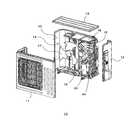
- FIG. 1 is an exploded perspective view of a heat exchange unit according to Embodiment 1 of the present invention.
- the heat exchange unit is the outdoor unit 10.
- the outer shell of the outdoor unit 10 is configured by the front panel 11, the side panel 12, and the top panel 13.
- the fan room 14 and the machine room 15 are separated by a partition plate 16.
- the fan room 14 is provided with a heat exchanger 20 and a fan 17 for supplying the heat exchanger 20 with outdoor air.
- a compressor 30 and a refrigerant pipe 40 which constitute a part of a refrigeration cycle apparatus described later, are provided in the lower part of the machine chamber 15.
- An electrical component 18 is provided at the top of the machine room 15.
- FIG. 2 is a refrigerant circuit diagram of the refrigeration cycle apparatus according to Embodiment 1 of the present invention.
- FIG. 2 is a view showing a refrigerant circuit related to the heating operation, and the flow of the refrigerant is indicated by an arrow.
- a compressor 30, a heat exchanger 50, a pressure reducing valve 60, a refrigerant distributor 70, and a heat exchanger 20 are sequentially connected by a refrigerant pipe 40.
- the refrigerant distributor 70 includes a distributor body 71, an inflow pipe 72 into which the refrigerant sealed in the refrigerant pipe 40 flows, and four distribution pipes 73A, 73B, 73C, and 73D into which the refrigerant flows out.
- the inflow pipe 72 is connected to the refrigerant pipe 40. That is, the refrigerant distributor 70 is connected between the pressure reducing valve 60 and the heat exchanger 20 in the refrigeration cycle apparatus 100.
- the compressor 30, the pressure reducing valve 60, the refrigerant distributor 70, and the heat exchanger 20 are provided in the outdoor unit 10 described above.
- the heat exchanger 50 is provided in the indoor unit 101. In the first embodiment, the heat exchanger 20 operates as an evaporator, and the heat exchanger 50 operates as a condenser.
- the outdoor unit 10 is a heat exchange unit of the present invention.
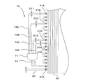
- FIG. 3 is a view showing the main part of the heat exchanger according to the first embodiment of the present invention.
- the four flow branch pipes 73A, 73B, 73C, and 73D are connected to the heat transfer pipes 21A, 21B, 21C, and 21D of the heat exchanger 20, respectively.
- the branch pipes 73A, 73B, 73C, and 73D may be collectively referred to as a branch pipe 73
- the heat transfer pipes 21A, 21B, 21C, and 21D may be collectively referred to as a heat transfer pipe 21.
- the height of the connection position of the flow dividing pipe 73A with the heat transfer pipe 21A is indicated by H11.
- the height of the connection position of the flow dividing pipe 73B with the heat transfer pipe 21B is indicated by H12.
- the height of the connection position of the flow dividing pipe 73C with the heat transfer pipe 21C is indicated by H13.
- the height of the connection position of the flow dividing pipe 73D with the heat transfer pipe 21D is indicated by H14.
- the height of the connection position of the flow dividing pipe 73 with the heat transfer pipe 21 is the length along the vertical direction of the heat exchanger 20 from the lowermost end of the heat exchanger 20 to the axial center of the flow dividing pipe 73. It is.
- the height H12 of the connecting position of the flow dividing pipe 73B with the heat transfer pipe 21B is lower than the height H11 of the connecting position of the flow dividing pipe 73A with the heat transfer pipe 21A, and the inner diameter D12 of the flow dividing pipe 73B is greater than the inner diameter D11 of the flow dividing pipe 73A. small.
- the height H13 of the connecting position of the flow dividing pipe 73C to the heat transfer pipe 21C is lower than the height H12 of the connecting position of the flow dividing pipe 73B to the heat transfer pipe 21B, and the inner diameter D13 of the flow dividing pipe 73C is greater than the inner diameter D12 of the flow dividing pipe 73B. small.
- the height H14 of the connecting position of the flow dividing pipe 73D with the heat transfer pipe 21D is lower than the height H13 of the connecting position of the flow dividing pipe 73C with the heat transfer pipe 21C, and the inner diameter D14 of the flow dividing pipe 73D is greater than the inner diameter D13 of the flow dividing pipe 73C. small. That is, the inner diameter of the flow dividing pipe 73 having a relatively low height at the connection position with the heat transfer pipe 21 is smaller than the inner diameter of the flow dividing pipe 73 having a relatively high height at the connection position with the heat transfer pipe 21.
- the flow rate of the refrigerant in the branch pipe 73 having a relatively low height at the connection position with the heat transfer pipe 21 is higher than the flow rate of the refrigerant in the flow branch pipe 73 with a relatively high height at the connection position with the heat transfer pipe 21.
- the inner diameter of the flow dividing pipe 73 having a relatively low height at the connection position with the heat transfer pipe 21 is a flow dividing pipe with a relatively high height at the connection position with the heat transfer pipe 21. Less than 73 inside diameter. Therefore, no deviation occurs in the amount of refrigerant in the plurality of flow dividing pipes 73, and deterioration in the path balance of the heat exchanger 20 operating as an evaporator and a reduction in the heat exchange rate can be prevented.
- the deterioration of the path balance of the heat exchanger 20 is prevented only by appropriately setting the inner diameter of the flow dividing pipe 73 connected to the distributor main body 71. That is, the heat exchange rate of the outdoor unit 10 and the refrigeration cycle apparatus 100 can be improved by providing the heat exchanger 20 with the refrigerant distributor 70 having a simple configuration and easy to manufacture.
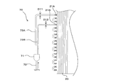
- FIG. 4 is a refrigerant circuit diagram of a refrigeration cycle apparatus according to Embodiment 2 of the present invention.
- FIG. 5 is a diagram showing a main part of a heat exchanger according to Embodiment 2 of the present invention. Similar to FIG. 2, FIG. 4 is a refrigerant circuit diagram related to the heating operation, and the flow of the refrigerant is indicated by an arrow.
- symbol is attached
- the inflow pipe 72 of the refrigerant distributor 70 is connected to the heat transfer pipe 21E of the heat exchanger 20. That is, the refrigerant distributor 70 is provided inside the heat exchanger 20 which is an evaporator.
- the other configuration is the same as that of the first embodiment, and the inner diameter of the flow dividing pipe 73 having a relatively low height at the connection position with the heat transfer pipe 21 is relatively high in the connection position with the heat transfer pipe 21. It is smaller than the inner diameter of the high flow dividing pipe 73.
- the inner diameter of the flow dividing pipe 73 having a relatively low height at the connection position with the heat transfer pipe 21 is the same as that of the flow dividing pipe 73 having a relatively high height at the connection position with the heat transfer pipe 21. Less than the inner diameter. Therefore, as in the first embodiment, no deviation occurs in the amount of refrigerant in the plurality of flow dividing pipes 73, and the deterioration of the path balance of the heat exchanger 20 operating as an evaporator and the reduction of the heat exchange rate are prevented. Can.
- the deterioration of the path balance of the heat exchanger 20 is prevented only by appropriately setting the inner diameter of the flow dividing pipe 73 connected to the distributor main body 71. That is, as in the first embodiment, the heat exchange rate of the outdoor unit 10 and the refrigeration cycle apparatus 100 can be improved by providing the heat exchanger 20 with the refrigerant distributor 70 having a simple configuration and easy to manufacture.
- FIG. 6 is a diagram showing a main part of a heat exchanger according to a modification of the first embodiment of the present invention.
- the refrigerant distributor 70 includes the four branch pipes 73A, 73B, 73C, and 73D, but the present invention is not limited to this.
- the refrigerant distributor 70 of the modified example shown in FIG. 6 has two branch pipes 73A and 73B.
- the height of the connecting position of the flow dividing pipe 73B with the heat transfer pipe 21B is lower than the height of the connecting position of the flow dividing pipe 73A with the heat transfer pipe 21A, and the inner diameter of the flow dividing pipe 73B is smaller than the inner diameter of the flow dividing pipe 73A. Therefore, the same effects as the effects of the first embodiment and the second embodiment described above can be obtained.
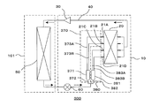
- FIG. 7 is a refrigerant circuit diagram of a refrigeration cycle apparatus according to Embodiment 3 of the present invention.
- FIG. 8 is a diagram showing a main part of a heat exchanger according to Embodiment 3 of the present invention. Similar to FIGS. 2 and 4, FIG. 7 is a refrigerant circuit diagram related to the heating operation, and the flow of the refrigerant is indicated by arrows.
- symbol is attached
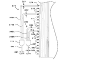
- the refrigerant distributor 370 and the refrigerant distributor 380 are provided in the refrigeration cycle apparatus 300.
- the refrigerant distributor 370 has a distributor body 371, an inflow pipe 372 into which the refrigerant sealed in the refrigerant pipe 40 flows, and two branch pipes 373A and 373B from which the refrigerant flows.
- the inflow pipe 372 is connected to the refrigerant pipe 40.
- the refrigerant distributor 380 has a distributor body 381, an inflow pipe 382 into which the refrigerant sealed in the refrigerant pipe 40 flows, and two branch pipes 383A and 383B from which the refrigerant flows.
- the inflow pipe 382 is connected to the refrigerant pipe 40. That is, the refrigerant distributor 370 and the refrigerant distributor 380 are connected between the pressure reducing valve 60 and the heat exchanger 20 in the refrigeration cycle apparatus 300.
- the two branch pipes 373A and 373B of the refrigerant distributor 370 are connected to the heat transfer pipes 21A and 21B of the heat exchanger 20, respectively.
- the two branch pipes 383A and 383B of the refrigerant distributor 380 are connected to the heat transfer pipes 21C and 21C of the heat exchanger 20, respectively.
- the branch pipes 373A and 373B may be collectively referred to as a branch pipe 373 and the branch pipes 383A and 383B may be collectively referred to as a branch pipe 383.
- the height of the connection position of the flow dividing pipe 373A with the heat transfer pipe 21A is indicated by H21.
- the height of the connection position of the flow dividing pipe 373B with the heat transfer pipe 21B is indicated by H22.
- the height of the connection position of the flow dividing pipe 383A with the heat transfer pipe 21C is indicated by H23.
- the height of the connecting position of the flow dividing pipe 383B to the heat transfer pipe 21D is indicated by H24.
- the average value of the heights of the connection positions of the plurality of flow dividing pipes 383A and 383B and the heat transfer pipes 21C and 21D in the refrigerant distributor 380 corresponds to the plurality of flow dividing pipes 373A and 373B and the heat transfer pipes 21A in the refrigerant distributor 370.
- 21B lower than the average value of the height of the connection position.
- the inner diameter D32 of the inflow pipe 382 of the refrigerant distributor 380 is smaller than the inner diameter D31 of the inflow pipe 372 of the refrigerant distributor 370.
- the inner diameter D32 of the inflow pipe 382 of the refrigerant distributor 380 which has a relatively low average value of the heights of the connection positions of the distribution pipe 383 and the heat transfer pipe 21, is the height of the connection position of the distribution pipe 373 and the heat transfer pipe 21.
- the average value of the pressure is smaller than the inner diameter D31 of the inflow pipe 372 of the refrigerant distributor 370, which is relatively high.
- the inner diameter of the flow dividing pipe 373 having a relatively low connection position with the heat transfer pipe 21 is smaller than the inner diameter of the flow dividing pipe 373 having a relatively high connection position with the heat transfer pipe 21. That is, the height H22 of the connection position of the flow dividing pipe 373B to the heat transfer pipe 21B is lower than the height H21 of the connection position of the flow dividing pipe 373A to the heat transfer pipe 21A, and the inner diameter D22 of the flow dividing pipe 373B is the inner diameter D21 of the flow dividing pipe 373A. Less than.
- the inner diameter of the flow dividing pipe 383 having a relatively low connection position with the heat transfer pipe 21 is smaller than the inner diameter of the flow dividing pipe 383 having a relatively high connection position with the heat transfer pipe 21. That is, the height H24 of the connection position of the flow dividing pipe 383B to the heat transfer pipe 21D is lower than the height H23 of the connection position of the flow dividing pipe 383A to the heat transfer pipe 21C, and the inner diameter D24 of the flow dividing pipe 383B is the inner diameter D23 of the flow dividing pipe 383A. Less than.
- the refrigerant flow rate in the branch pipe 383 having a relatively low height at the connection position with the heat transfer pipe 21 is higher than the refrigerant flow rate in the distribution pipe 373 with a relatively high height at the connection position with the heat transfer pipe 21. Will also grow.
- the inner diameter D32 of the inflow pipe 382 of the refrigerant distributor 380 having the flow dividing pipe 383 having a relatively low average value of the height of the connection position with the heat transfer pipe 21 is the height of the connection position with the heat transfer pipe 21. Is smaller than the inner diameter D31 of the inflow pipe 372 of the refrigerant distributor 370 having a relatively high flow distribution pipe 373.
- connection positions with the heat transfer pipe 21 of the refrigerant distributor 370 and the distribution pipe 383 of the refrigerant distributor 380 are relatively low. Smaller than the inner diameter of the Therefore, the refrigerant path balance in the heat exchanger 20 can be made more appropriate, and a high heat exchange rate can be maintained.
- the deterioration of the path balance of the heat exchanger 20 is prevented only by appropriately setting the inner diameters of the flow dividing pipe 73 and the flow dividing pipe 83, and the inner diameters of the inflow pipe 372 and the inflow pipe 382. ing. That is, the heat exchange rate of the outdoor unit 10 and the refrigeration cycle apparatus 200 can be improved by providing the heat exchanger 20 with the refrigerant distributor 370 and the refrigerant distributor 380 which have a simple configuration and are easy to manufacture.
- FIG. 9 is a refrigerant circuit diagram of a refrigeration cycle apparatus according to Embodiment 4 of the present invention.
- FIG. 10 is a diagram showing a main part of a heat exchanger according to Embodiment 4 of the present invention. Similar to FIGS. 2, 4 and 7, FIG. 9 is a refrigerant circuit diagram related to the heating operation, and the flow of the refrigerant is indicated by arrows.
- FIGS. 9 and 10 the same components as the components of the refrigeration cycle apparatus according to the first to third embodiments described above are designated by the same reference numerals.
- the inflow pipe 372 of the refrigerant distributor 370 is connected to the heat transfer pipe 21E of the heat exchanger 20, and the inflow pipe 382 of the refrigerant distributor 380 is a transmission of the heat exchanger 20. It is connected to the heat pipe 21F. That is, the refrigerant distributor 370 and the refrigerant distributor 380 are provided inside the heat exchanger 20 which is an evaporator.
- the other configuration is the same as that of the third embodiment.
- the inner diameter D32 of the inflow pipe 382 of the refrigerant distributor 380 having the flow dividing pipe 383 having a relatively low average value of the height of the connection position with the heat transfer pipe 21 is the connection position with the heat transfer pipe 21. Is smaller than the inner diameter D31 of the inflow pipe 372 of the refrigerant distributor 370 having the flow distribution pipe 373 having a relatively high height. Therefore, as in the third embodiment, no deviation occurs in the amount of refrigerant in the plurality of flow dividing pipes 373 and the flow dividing pipe 383, and deterioration of the refrigerant's path balance in the heat exchanger 20 operating as an evaporator and the heat exchange rate Can be prevented.
- connection positions with the heat transfer pipe 21 of the refrigerant distributor 370 and the distribution pipe 383 of the refrigerant distributor 380 are relatively low. Smaller than the inner diameter of the Therefore, as in the third embodiment, the path balance of the refrigerant in the heat exchanger 20 can be made more appropriate, and a high heat exchange rate can be maintained.
- the deterioration of the path balance of the heat exchanger 20 is prevented only by appropriately setting the inner diameters of the flow dividing pipe 73 and the flow dividing pipe 83, and the inner diameters of the inflow pipe 372 and the inflow pipe 382. ing. That is, as in the third embodiment, the heat exchanger 20 is provided with the refrigerant distributor 370 and the refrigerant distributor 380 which are simple in structure and easy to improve in improving the heat exchange rates of the outdoor unit 10 and the refrigeration cycle apparatus 200. It can be realized by providing.
- FIG. 11 is a diagram showing a main part of a heat exchanger according to a modification of the third embodiment of the present invention. As shown in FIG. 11, the inner diameter D21 of the flow dividing pipe 373A, the inner diameter D22 of the flow dividing pipe 373B, the inner diameter D23 of the flow dividing pipe 383A, and the inner diameter D24 of the flow dividing pipe 383B may be the same.
- the inner diameter D32 of the inflow pipe 382 of the refrigerant distributor 380 is smaller than the inner diameter D31 of the inflow pipe 372 of the refrigerant distributor 370. Therefore, the same effects as those of the third and fourth embodiments described above can be obtained.
- the refrigerant distributor 370 and the refrigerant distributor 380 shown in FIG. 11 are connected between the pressure reducing valve 60 and the heat exchanger 20 as in the third embodiment, but are limited thereto Alternatively, as in the fourth embodiment, the heat exchanger 20 may be provided inside.
- FIG. 12 is a view showing the main part of a heat exchanger according to Embodiment 5 of the present invention.
- the refrigerant distributor 470 has a distributor body 471, an inflow pipe 472 into which the refrigerant flows, and branch pipes 473A and 473B in which the refrigerant flows out.
- the flow dividing pipe 473A is connected to the heat transfer pipe 21A of the heat exchanger 20, and the flow dividing pipe 473B is connected to the heat transfer pipe 21C of the heat exchanger 20.
- the refrigerant distributor 480 has a distributor body 481, an inflow pipe 482 into which the refrigerant flows, and branch pipes 483A and 483B from which the refrigerant flows out.
- the flow dividing pipe 483A is connected to the heat transfer pipe 21B of the heat exchanger 20, and the flow dividing pipe 483B is connected to the heat transfer pipe 21D of the heat exchanger 20.
- the inflow pipe 472 and the inflow pipe 482 are connected to the same refrigerant pipe as the refrigerant pipe 40 of the above-described refrigerant circuit.
- the branch pipes 473A and 473B may be collectively referred to as a branch pipe 473
- the branch pipes 483A and 483B may be collectively referred to as a branch pipe 483.
- the average value of the height H43 of the connection position of the dividing pipe 483A and the heat transfer pipe 21B and the height H44 of the connecting position of the dividing pipe 483B and the heat transfer pipe 21D is the height H41 of the connecting position of the dividing pipe 473A and the heat transfer pipe 21A. This is lower than the average value of the height H42 of the connection position of the flow dividing pipe 473B and the heat transfer pipe 21C.
- the connection position of the distribution pipe 483A at the highest connection position with the heat transfer pipe 21 is higher than the connection position of the distribution pipe 473B at the lowest connection position with the heat transmission pipe 21 in the refrigerant distributor 470.
- connection position of the flow dividing pipe 483B of the refrigerant distributor 480 and the heat transfer pipe 21A is higher than the connection position of the flow dividing pipe 473B of the refrigerant distributor 470 and the heat transfer pipe 21C.
- the inner diameter D42 of the inflow pipe 482 of the refrigerant distributor 480 is smaller than the inner diameter D41 of the inflow pipe 472 of the refrigerant distributor 470.
- connection position of a part of flow dividing pipe 473 and heat transfer pipe 21 of refrigerant distributor 470 and the part of flow dividing pipe 483 of refrigerant distributor 480 which is separate from refrigerant distributor 470 are transmitted.
- the connection position with the heat pipe 21 is up and down.
- the inner diameter D42 of the inflow pipe 482 of the refrigerant distributor 480 which has a low average value of the heights of the connection positions of the distribution pipe 483 and the heat transfer pipe 21, is the height of the connection position of the distribution pipe 473 and the heat transfer pipe 21. Is smaller than the inner diameter D41 of the inflow pipe 472 of the refrigerant distributor 470, which has a high average value. Therefore, even in the case where the connection positions of the flow dividing tubes of different refrigerant distributors are up and down, the same effects as those of the above-described first to fourth embodiments can be obtained.
- FIG. 13 is a diagram showing a main part of a heat exchanger according to Embodiment 6 of the present invention.
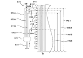
- the refrigerant distributor 570 includes a distributor body 571, an inflow pipe 572 into which the refrigerant flows, and branch pipes 573 A, 573 B, 573 C, and 573 D in which the refrigerant flows out.
- the branch pipe 573A is connected to the heat transfer pipe 21A of the heat exchanger 20
- the branch pipe 573B is connected to the heat transfer pipe 21B of the heat exchanger 20
- the branch pipe 573C is connected to the heat transfer pipe 21C of the heat exchanger 20
- the branch pipe 573D is connected to the heat transfer tube 21D of the heat exchanger 20.
- the branch pipes 573A, 573B, 573C, and 573D may be collectively referred to as a branch pipe 573.
- the height H52 of the connecting position of the flow dividing pipe 573B to the heat transfer pipe 21B is lower than the height H51 of the connecting position of the flow dividing pipe 573A to the heat transfer pipe 21A.
- the height H53 of the connecting position of the flow dividing pipe 573C to the heat transfer pipe 21C is lower than the height H52 of the connecting position of the flow dividing pipe 573B to the heat transfer pipe 21B.
- the height H54 of the connecting position of the flow dividing pipe 573D to the heat transfer pipe 21D is lower than the height H53 of the connecting position of the flow dividing pipe 573C to the heat transfer pipe 21C.
- the inner diameter D51 of the flow dividing pipe 573A, the inner diameter D52 of the flow dividing pipe 573B, and the inner diameter D53 of the flow dividing pipe 573C are the same, and the inner diameter D54 of the flow dividing pipe 573D is the inner diameter D51, D52 of the flow dividing pipes 573A, 573B, and 573C. And less than D53. That is, the inner diameters of the three flow dividing pipes 573A, the flow dividing pipe 573B, and the flow dividing pipe 573C, which are relatively high in height at the connection position with the heat transfer pipe 21, are the same, and the connection positions with the heat transfer pipe 21 are high. Is relatively smaller than the inner diameter of the relatively low diverter tube 573D.
- deterioration of the path balance of the refrigerant in the heat exchanger 20 can be prevented, and in addition to the reduction of the heat exchange rate being prevented, two types of four split pipes 573 having different inner diameters are used. The thing is used. Thus, the manufacture of the heat exchanger is easier.
- FIG. 14 is a diagram showing a main part of a heat exchanger according to a modification of the sixth embodiment of the present invention.
- the inner diameter D52 of the flow dividing pipe 573B, the inner diameter D53 of the flow dividing pipe 573C, and the inner diameter D54 of the flow dividing pipe 573D are the same, and the inner diameter D51 of the flow dividing pipe 573A is the inner diameter D52 of the flow dividing pipes 573B, 573C, and 573D. , D53, and D54.
- the inner diameters of the three flow dividing pipes 573B, the flow dividing pipe 573C, and the flow dividing pipe 573D which are relatively low in height at the connection position with the heat transfer pipe 21 are the same, and the connection positions with the heat transfer pipe 21 are high. Is relatively smaller than the inner diameter of the relatively high flow dividing pipe 573A. Therefore, also in this modification, the same effect as in the above-described sixth embodiment can be obtained.
- the inner diameters of the three flow dividing tubes 573 among the four flow dividing tubes 573 are the same, and the inner diameter of the remaining one flow dividing pipe 573 is connected to the heat transfer tube 21.
- the inner diameter of the flow dividing pipe 573 may be set as follows. That is, the inner diameters of the two flow dividing pipes 573 whose connection position to the heat transfer pipe 21 is relatively low are made smaller than the inner diameters of the two flow dividing pipes 573 whose connection position to the heat transfer pipe 21 is relatively high.
- the inner diameters of the two flow dividing pipes 573 having relatively low connection positions with the heat transfer pipe 21 are the same, and the inner diameters of the two flow dividing pipes 573 with relatively high connection positions with the heat transfer pipe 21 are the same. I assume. As described above, the number of types of flow dividing tubes 573 is reduced according to the connection condition with the heat transfer pipes 21 with respect to the number of flow dividing pipes 573 connected to the heat transfer pipes 21, thereby making the heat exchanger more It can be easy.
- Embodiment 6 and its modification although a refrigerant
- the refrigerant circuit related to the heating operation has been described as an example, but the present invention is not limited to this.
- the refrigerant distributors according to the first to sixth embodiments can also be applied to a heat exchanger that constitutes a refrigerant circuit for cooling operation.
- the outdoor unit comprises the compressor 30, the heat exchanger 50, and the pressure reducing valve 60
- the indoor unit is a thermal unit. It comprises the exchanger 20 and the refrigerant distributor 70.
- the inner diameters of the plurality of flow dividing tubes 73 of the refrigerant distributor 70 can be configured as described above to prevent the deterioration of the path balance of the heat exchanger 20 operating as the evaporator and the reduction of the heat exchange rate.
Landscapes
- Engineering & Computer Science (AREA)
- Physics & Mathematics (AREA)
- Mechanical Engineering (AREA)
- Thermal Sciences (AREA)
- General Engineering & Computer Science (AREA)
- Heat-Exchange Devices With Radiators And Conduit Assemblies (AREA)
Abstract
Description
図1は、本発明の実施の形態1に係る熱交換ユニットの分解斜視図である。図1に示すように、本実施の形態1において、熱交換ユニットは室外機10である。室外機10の外郭は、前面パネル11、側面パネル12及び天面パネル13によって構成されている。室外機10の内部には、送風機室14と機械室15とが形成されている。送風機室14と機械室15とは仕切板16によって仕切られている。
図4は、本発明の実施の形態2に係る冷凍サイクル装置の冷媒回路図である。図5は、本発明の実施の形態2に係る熱交換器の要部を示す図である。図2と同様、図4は暖房運転に係る冷媒回路図であり、冷媒の流れは矢印で示されている。図4及び図5において、上述の実施の形態1に係る冷凍サイクル装置の構成要素と同一の構成要素には同一の符号が付されている。本実施の形態2の冷凍サイクル装置200において、冷媒分配器70の流入管72は、熱交換器20の伝熱管21Eに接続されている。すなわち、冷媒分配器70は蒸発器である熱交換器20の内部に設けられている。その他の構成は、実施の形態1と同様であり、伝熱管21との接続位置の高さが相対的に低い分流管73の内径は、伝熱管21との接続位置の高さが相対的に高い分流管73の内径より小さい。
図7は、本発明の実施の形態3に係る冷凍サイクル装置の冷媒回路図である。図8は、本発明の実施の形態3に係る熱交換器の要部を示す図である。図2及び図4と同様、図7は暖房運転に係る冷媒回路図であり、冷媒の流れは矢印で示されている。図7及び図8において、上述の実施の形態1及び実施の形態2に係る冷凍サイクル装置の構成要素と同一の構成要素には同一の符号が付されている。本実施の形態3において、冷媒分配器370及び冷媒分配器380が冷凍サイクル装置300に設けられている。冷媒分配器370は、分配器本体371と、冷媒配管40に封入されている冷媒が流入する流入管372と、冷媒が流出する2つの分流管373A及び分流管373Bとを有している。流入管372は、冷媒配管40に接続されている。冷媒分配器380は、分配器本体381と、冷媒配管40に封入されている冷媒が流入する流入管382と、冷媒が流出する2つの分流管383A及び分流管383Bとを有している。流入管382は、冷媒配管40に接続されている。すなわち、冷媒分配器370及び冷媒分配器380は、冷凍サイクル装置300において減圧弁60と熱交換器20との間に接続されている。
図9は、本発明の実施の形態4に係る冷凍サイクル装置の冷媒回路図である。図10は、本発明の実施の形態4に係る熱交換器の要部を示す図である。図2、図4、及び図7と同様、図9は暖房運転に係る冷媒回路図であり、冷媒の流れは矢印で示されている。図9及び図10において、上述の実施の形態1~3に係る冷凍サイクル装置の構成要素と同一の構成要素には同一の符号が付されている。本実施の形態4の冷凍サイクル装置200において、冷媒分配器370の流入管372は、熱交換器20の伝熱管21Eに接続され、冷媒分配器380の流入管382は、熱交換器20の伝熱管21Fに接続されている。すなわち、冷媒分配器370及び冷媒分配器380は蒸発器である熱交換器20の内部に設けられている。その他の構成は、実施の形態3と同様である。
図12は、本発明の実施の形態5に係る熱交換器の要部を示す図である。冷媒分配器470は、分配器本体471と、冷媒が流入する流入管472と、冷媒が流出する分流管473A及び473Bとを有している。分流管473Aは熱交換器20の伝熱管21Aに接続され、分流管473Bは熱交換器20の伝熱管21Cに接続されている。冷媒分配器480は、分配器本体481と、冷媒が流入する流入管482と、冷媒が流出する分流管483A及び483Bとを有している。分流管483Aは熱交換器20の伝熱管21Bに接続され、分流管483Bは熱交換器20の伝熱管21Dに接続されている。流入管472及び流入管482は、上述の冷媒回路の冷媒配管40と同様の冷媒配管に接続されている。以降の説明において、分流管473A及び473Bを総称して分流管473と呼び、分流管483A及び483Bを総称して分流管483と呼ぶ場合がある。
図13は、本発明の実施の形態6に係る熱交換器の要部を示す図である。冷媒分配器570は、分配器本体571と、冷媒が流入する流入管572と、冷媒が流出する分流管573A、573B、573C、及び573Dとを有している。分流管573Aは熱交換器20の伝熱管21Aに接続され、分流管573Bは熱交換器20の伝熱管21Bに接続され、分流管573Cは熱交換器20の伝熱管21Cに接続され、分流管573Dは熱交換器20の伝熱管21Dに接続されている。以降の説明において、分流管573A、573B、573C、及び573Dを総称して分流管573と呼ぶ場合がある。
Claims (8)
- 複数の伝熱管を有する熱交換器と、
少なくとも1つの冷媒分配器とを備える熱交換ユニットであって、
前記冷媒分配器は、
冷媒が流入する流入管と、
前記冷媒が流出する複数の分流管であって、それぞれ前記複数の伝熱管に接続されている複数の分流管とを備え、
前記複数の分流管のうち前記伝熱管との接続位置の高さが相対的に低い分流管の内径が、前記複数の分流管のうち前記伝熱管との接続位置の高さが相対的に高い分流管の内径より小さい熱交換ユニット。 - 複数の伝熱管を有する熱交換器と、
複数の冷媒分配器とを備える熱交換ユニットであって、
前記複数の冷媒分配器は、
冷媒が流入する流入管と、
前記冷媒が流出する複数の分流管であって、それぞれ前記複数の伝熱管に接続されている複数の分流管とを備え、
前記複数の分流管と前記複数の伝熱管との接続位置の高さの平均値が相対的に低い前記冷媒分配器の前記流入管の内径が、前記複数の分流管と前記複数の伝熱管との接続位置の高さの平均値が相対的に高い前記冷媒分配器の前記流入管の内径より小さい熱交換ユニット。 - 前記複数の冷媒分配器のそれぞれにおいて、前記複数の分流管のうち前記伝熱管との接続位置の高さが相対的に低い前記分流管の内径が、前記複数の分流管のうち前記伝熱管との接続位置の高さが相対的に高い前記分流管の内径よりも小さい請求項2に記載の熱交換ユニット。
- 前記複数の分流管と前記複数の伝熱管との接続位置の高さの平均値が相対的に低い前記冷媒分配器の前記複数の分流管のうち、前記伝熱管との接続位置の高さが最も高い前記分流管の該接続位置は、前記複数の分流管と前記複数の伝熱管との接続位置の高さの平均値が相対的に高い前記冷媒分配器の前記複数の分流管のうち、前記伝熱管との接続位置の高さが最も低い前記分流管の該接続位置より高い請求項2又は3に記載の熱交換ユニット。
- 圧縮機、凝縮器、減圧弁及び蒸発器を冷媒配管によって順次接続した冷媒回路と、少なくとも1つの冷媒分配器とを備える冷凍サイクル装置であって、
前記冷媒分配器は、
前記冷媒回路内の冷媒が流入する流入管と、
前記冷媒が流出する複数の分流管であって、それぞれ前記蒸発器の複数の伝熱管に接続されている分流管とを有し、
前記複数の分流管のうち前記伝熱管との接続位置の高さが相対的に低い分流管の内径が、前記複数の分流管のうち前記伝熱管との接続位置の高さが相対的に高い分流管の内径より小さい冷凍サイクル装置。 - 圧縮機、凝縮器、減圧弁及び蒸発器を冷媒配管によって順次接続した冷媒回路と、複数の冷媒分配器とを備えた冷凍サイクル装置であって、
前記複数の冷媒分配器は、
前記冷媒回路内の冷媒が流入する流入管と、
前記冷媒が流出する複数の分流管であって、それぞれ前記蒸発器の複数の伝熱管に接続されている分流管とを有し、
前記複数の分流管と前記複数の伝熱管との接続位置の高さの平均値が相対的に低い前記冷媒分配器の前記流入管の内径が、前記複数の分流管と前記複数の伝熱管との接続位置の高さの平均値が相対的に高い前記冷媒分配器の前記流入管の内径より小さい冷凍サイクル装置。 - 前記冷媒分配器は、前記減圧弁と前記蒸発器との間に接続されている請求項5又は6に記載の冷凍サイクル装置。
- 前記冷媒分配器は前記蒸発器の内部に設けられている請求項5又は6に記載の冷凍サイクル装置。
Priority Applications (6)
| Application Number | Priority Date | Filing Date | Title |
|---|---|---|---|
| EP17882269.8A EP3467405B1 (en) | 2017-08-08 | 2017-08-08 | Heat exchange unit and refrigeration cycle device |
| PCT/JP2017/028707 WO2019030812A1 (ja) | 2017-08-08 | 2017-08-08 | 熱交換ユニット及び冷凍サイクル装置 |
| EP19202275.4A EP3614075B1 (en) | 2017-08-08 | 2017-08-08 | Heat exchange unit and refrigeration cycle apparatus |
| CN201780093588.1A CN111033150B (zh) | 2017-08-08 | 2017-08-08 | 热交换单元以及制冷循环装置 |
| US16/620,928 US11199345B2 (en) | 2017-08-08 | 2017-08-08 | Heat exchange unit and refrigeration cycle apparatus |
| JP2019535465A JP6818895B2 (ja) | 2017-08-08 | 2017-08-08 | 熱交換ユニット及び冷凍サイクル装置 |
Applications Claiming Priority (1)
| Application Number | Priority Date | Filing Date | Title |
|---|---|---|---|
| PCT/JP2017/028707 WO2019030812A1 (ja) | 2017-08-08 | 2017-08-08 | 熱交換ユニット及び冷凍サイクル装置 |
Publications (1)
| Publication Number | Publication Date |
|---|---|
| WO2019030812A1 true WO2019030812A1 (ja) | 2019-02-14 |
Family
ID=65271198
Family Applications (1)
| Application Number | Title | Priority Date | Filing Date |
|---|---|---|---|
| PCT/JP2017/028707 Ceased WO2019030812A1 (ja) | 2017-08-08 | 2017-08-08 | 熱交換ユニット及び冷凍サイクル装置 |
Country Status (5)
| Country | Link |
|---|---|
| US (1) | US11199345B2 (ja) |
| EP (2) | EP3467405B1 (ja) |
| JP (1) | JP6818895B2 (ja) |
| CN (1) | CN111033150B (ja) |
| WO (1) | WO2019030812A1 (ja) |
Cited By (1)
| Publication number | Priority date | Publication date | Assignee | Title |
|---|---|---|---|---|
| CN111520934A (zh) * | 2020-05-18 | 2020-08-11 | 浙江盾安热工科技有限公司 | 换热器及具有其的空调器 |
Families Citing this family (3)
| Publication number | Priority date | Publication date | Assignee | Title |
|---|---|---|---|---|
| CN113790548A (zh) * | 2020-11-09 | 2021-12-14 | 四川贝园科技有限公司 | 一种蒸发式冷凝器 |
| CN112944755B (zh) * | 2021-03-31 | 2022-07-08 | 哈尔滨商业大学 | 一种用于空调的制冷剂调节装置 |
| CN114811848A (zh) * | 2022-05-27 | 2022-07-29 | 珠海格力电器股份有限公司 | 管路结构、换热装置及空调器 |
Citations (8)
| Publication number | Priority date | Publication date | Assignee | Title |
|---|---|---|---|---|
| JPS59108169U (ja) * | 1983-01-13 | 1984-07-20 | 三菱重工業株式会社 | 空気熱交換器 |
| JPH1019416A (ja) * | 1996-07-03 | 1998-01-23 | Toshiba Corp | 熱交換器 |
| JP2000274885A (ja) | 1999-03-25 | 2000-10-06 | Sharp Corp | 分岐管及び分岐管を備えた空気調和機 |
| JP2007248006A (ja) * | 2006-03-17 | 2007-09-27 | Sanyo Electric Co Ltd | 冷媒サイクル装置 |
| JP2008075929A (ja) * | 2006-09-20 | 2008-04-03 | Matsushita Electric Ind Co Ltd | 冷凍機 |
| WO2015111220A1 (ja) * | 2014-01-27 | 2015-07-30 | 三菱電機株式会社 | 熱交換器、及び、空気調和装置 |
| US20160033179A1 (en) * | 2014-08-01 | 2016-02-04 | Lg Electronics Inc. | Air conditioner |
| JP2017101857A (ja) * | 2015-11-30 | 2017-06-08 | ダイキン工業株式会社 | 冷凍装置 |
Family Cites Families (6)
| Publication number | Priority date | Publication date | Assignee | Title |
|---|---|---|---|---|
| JP5071685B2 (ja) * | 2008-12-01 | 2012-11-14 | 株式会社富士通ゼネラル | 空気調和機 |
| CN201539997U (zh) * | 2009-12-01 | 2010-08-04 | 海信(山东)空调有限公司 | 一种高效冷凝器及安装有该冷凝器的空调器 |
| JP6108332B2 (ja) * | 2012-07-20 | 2017-04-05 | ジョンソンコントロールズ ヒタチ エア コンディショニング テクノロジー(ホンコン)リミテッド | 空気調和機 |
| JP6474226B2 (ja) * | 2014-10-15 | 2019-02-27 | 三菱電機株式会社 | 熱交換器及びこれを備えた冷凍サイクル装置 |
| US10788243B2 (en) * | 2016-08-29 | 2020-09-29 | Advanced Distributor Products Llc | Refrigerant distributor for aluminum coils |
| CN206146052U (zh) * | 2016-10-17 | 2017-05-03 | 珠海格力电器股份有限公司 | 多排换热器和包括该多排换热器的空调器 |
-
2017
- 2017-08-08 US US16/620,928 patent/US11199345B2/en active Active
- 2017-08-08 EP EP17882269.8A patent/EP3467405B1/en active Active
- 2017-08-08 WO PCT/JP2017/028707 patent/WO2019030812A1/ja not_active Ceased
- 2017-08-08 EP EP19202275.4A patent/EP3614075B1/en active Active
- 2017-08-08 JP JP2019535465A patent/JP6818895B2/ja not_active Expired - Fee Related
- 2017-08-08 CN CN201780093588.1A patent/CN111033150B/zh not_active Expired - Fee Related
Patent Citations (8)
| Publication number | Priority date | Publication date | Assignee | Title |
|---|---|---|---|---|
| JPS59108169U (ja) * | 1983-01-13 | 1984-07-20 | 三菱重工業株式会社 | 空気熱交換器 |
| JPH1019416A (ja) * | 1996-07-03 | 1998-01-23 | Toshiba Corp | 熱交換器 |
| JP2000274885A (ja) | 1999-03-25 | 2000-10-06 | Sharp Corp | 分岐管及び分岐管を備えた空気調和機 |
| JP2007248006A (ja) * | 2006-03-17 | 2007-09-27 | Sanyo Electric Co Ltd | 冷媒サイクル装置 |
| JP2008075929A (ja) * | 2006-09-20 | 2008-04-03 | Matsushita Electric Ind Co Ltd | 冷凍機 |
| WO2015111220A1 (ja) * | 2014-01-27 | 2015-07-30 | 三菱電機株式会社 | 熱交換器、及び、空気調和装置 |
| US20160033179A1 (en) * | 2014-08-01 | 2016-02-04 | Lg Electronics Inc. | Air conditioner |
| JP2017101857A (ja) * | 2015-11-30 | 2017-06-08 | ダイキン工業株式会社 | 冷凍装置 |
Non-Patent Citations (1)
| Title |
|---|
| See also references of EP3467405A4 |
Cited By (1)
| Publication number | Priority date | Publication date | Assignee | Title |
|---|---|---|---|---|
| CN111520934A (zh) * | 2020-05-18 | 2020-08-11 | 浙江盾安热工科技有限公司 | 换热器及具有其的空调器 |
Also Published As
| Publication number | Publication date |
|---|---|
| CN111033150B (zh) | 2022-02-01 |
| CN111033150A (zh) | 2020-04-17 |
| US20200200450A1 (en) | 2020-06-25 |
| US11199345B2 (en) | 2021-12-14 |
| EP3467405A1 (en) | 2019-04-10 |
| EP3614075A2 (en) | 2020-02-26 |
| JP6818895B2 (ja) | 2021-01-20 |
| JPWO2019030812A1 (ja) | 2020-04-23 |
| EP3614075B1 (en) | 2022-07-20 |
| EP3614075A3 (en) | 2020-04-22 |
| EP3467405A4 (en) | 2019-04-10 |
| EP3467405B1 (en) | 2020-02-19 |
Similar Documents
| Publication | Publication Date | Title |
|---|---|---|
| KR101462176B1 (ko) | 열교환기 | |
| US10670344B2 (en) | Heat exchanger, air-conditioning apparatus, refrigeration cycle apparatus and method for manufacturing heat exchanger | |
| AU2014410872B2 (en) | Laminated header, heat exchanger, and air-conditioning apparatus | |
| US10168083B2 (en) | Refrigeration system and heat exchanger thereof | |
| US20180292096A1 (en) | Outdoor unit and indoor unit of air-conditioning apparatus | |
| JP5738781B2 (ja) | 空気調和装置 | |
| US11333369B2 (en) | Refrigerant distributor, heat exchanger, and air-conditioning apparatus | |
| JPWO2013161038A1 (ja) | 熱交換器、冷凍サイクル装置、空気調和機及び熱交換方法 | |
| JP6818895B2 (ja) | 熱交換ユニット及び冷凍サイクル装置 | |
| JP2016038192A (ja) | パラレルフロー型熱交換器および空気調和機 | |
| JP2015203506A (ja) | 熱交換器 | |
| EP3540318B1 (en) | Indoor unit for air conditioner, and air conditioner | |
| KR20170067351A (ko) | 열교환기 | |
| JP2020051632A (ja) | 熱交換器、及び、これを備える空気調和機 | |
| CN106403397A (zh) | 换热器、空调室外机和空调器 | |
| JP2015175533A (ja) | 空調機の熱交換器 | |
| CN205102469U (zh) | 热交换器以及具备该热交换器的制冷循环装置 | |
| JPWO2014068687A1 (ja) | パラレルフロー型熱交換器及びこれを用いた空気調和気 | |
| JP7102686B2 (ja) | 熱交換器 | |
| JP6253513B2 (ja) | 空気調和機の室内ユニット | |
| JP5237244B2 (ja) | 分配器及びこれを含む空調装置 | |
| JP2020085268A (ja) | 熱交換器 | |
| WO2016151655A1 (ja) | 空気調和装置及びその性能判定方法 | |
| CN109073334B (zh) | 换热器以及空调机 | |
| JPWO2018142567A1 (ja) | 空気調和装置 |
Legal Events
| Date | Code | Title | Description |
|---|---|---|---|
| WWE | Wipo information: entry into national phase |
Ref document number: 2017882269 Country of ref document: EP |
|
| ENP | Entry into the national phase |
Ref document number: 2017882269 Country of ref document: EP Effective date: 20180614 |
|
| 121 | Ep: the epo has been informed by wipo that ep was designated in this application |
Ref document number: 17882269 Country of ref document: EP Kind code of ref document: A1 |
|
| ENP | Entry into the national phase |
Ref document number: 2019535465 Country of ref document: JP Kind code of ref document: A |
|
| NENP | Non-entry into the national phase |
Ref country code: DE |