WO2019030836A1 - 電動機の駆動装置及び空気調和機 - Google Patents
電動機の駆動装置及び空気調和機 Download PDFInfo
- Publication number
- WO2019030836A1 WO2019030836A1 PCT/JP2017/028828 JP2017028828W WO2019030836A1 WO 2019030836 A1 WO2019030836 A1 WO 2019030836A1 JP 2017028828 W JP2017028828 W JP 2017028828W WO 2019030836 A1 WO2019030836 A1 WO 2019030836A1
- Authority
- WO
- WIPO (PCT)
- Prior art keywords
- wiring
- motor
- connection
- phase
- noise
- Prior art date
- Legal status (The legal status is an assumption and is not a legal conclusion. Google has not performed a legal analysis and makes no representation as to the accuracy of the status listed.)
- Ceased
Links
Images




Classifications
-
- H—ELECTRICITY
- H02—GENERATION; CONVERSION OR DISTRIBUTION OF ELECTRIC POWER
- H02P—CONTROL OR REGULATION OF ELECTRIC MOTORS, ELECTRIC GENERATORS OR DYNAMO-ELECTRIC CONVERTERS; CONTROLLING TRANSFORMERS, REACTORS OR CHOKE COILS
- H02P25/00—Arrangements or methods for the control of AC motors characterised by the kind of AC motor or by structural details
- H02P25/16—Arrangements or methods for the control of AC motors characterised by the kind of AC motor or by structural details characterised by the circuit arrangement or by the kind of wiring
- H02P25/18—Arrangements or methods for the control of AC motors characterised by the kind of AC motor or by structural details characterised by the circuit arrangement or by the kind of wiring with arrangements for switching the windings, e.g. with mechanical switches or relays
- H02P25/184—Arrangements or methods for the control of AC motors characterised by the kind of AC motor or by structural details characterised by the circuit arrangement or by the kind of wiring with arrangements for switching the windings, e.g. with mechanical switches or relays wherein the motor speed is changed by switching from a delta to a star, e.g. wye, connection of its windings, or vice versa
-
- F—MECHANICAL ENGINEERING; LIGHTING; HEATING; WEAPONS; BLASTING
- F25—REFRIGERATION OR COOLING; COMBINED HEATING AND REFRIGERATION SYSTEMS; HEAT PUMP SYSTEMS; MANUFACTURE OR STORAGE OF ICE; LIQUEFACTION SOLIDIFICATION OF GASES
- F25B—REFRIGERATION MACHINES, PLANTS OR SYSTEMS; COMBINED HEATING AND REFRIGERATION SYSTEMS; HEAT PUMP SYSTEMS
- F25B1/00—Compression machines, plants or systems with non-reversible cycle
-
- H—ELECTRICITY
- H02—GENERATION; CONVERSION OR DISTRIBUTION OF ELECTRIC POWER
- H02M—APPARATUS FOR CONVERSION BETWEEN AC AND AC, BETWEEN AC AND DC, OR BETWEEN DC AND DC, AND FOR USE WITH MAINS OR SIMILAR POWER SUPPLY SYSTEMS; CONVERSION OF DC OR AC INPUT POWER INTO SURGE OUTPUT POWER; CONTROL OR REGULATION THEREOF
- H02M7/00—Conversion of AC power input into DC power output; Conversion of DC power input into AC power output
- H02M7/42—Conversion of DC power input into AC power output without possibility of reversal
- H02M7/44—Conversion of DC power input into AC power output without possibility of reversal by static converters
- H02M7/48—Conversion of DC power input into AC power output without possibility of reversal by static converters using discharge tubes with control electrode or semiconductor devices with control electrode
- H02M7/53—Conversion of DC power input into AC power output without possibility of reversal by static converters using discharge tubes with control electrode or semiconductor devices with control electrode using devices of a triode or transistor type requiring continuous application of a control signal
- H02M7/537—Conversion of DC power input into AC power output without possibility of reversal by static converters using discharge tubes with control electrode or semiconductor devices with control electrode using devices of a triode or transistor type requiring continuous application of a control signal using semiconductor devices only, e.g. single switched pulse inverters
- H02M7/5387—Conversion of DC power input into AC power output without possibility of reversal by static converters using discharge tubes with control electrode or semiconductor devices with control electrode using devices of a triode or transistor type requiring continuous application of a control signal using semiconductor devices only, e.g. single switched pulse inverters in a bridge configuration
- H02M7/53871—Conversion of DC power input into AC power output without possibility of reversal by static converters using discharge tubes with control electrode or semiconductor devices with control electrode using devices of a triode or transistor type requiring continuous application of a control signal using semiconductor devices only, e.g. single switched pulse inverters in a bridge configuration with automatic control of output voltage or current
-
- H—ELECTRICITY
- H02—GENERATION; CONVERSION OR DISTRIBUTION OF ELECTRIC POWER
- H02P—CONTROL OR REGULATION OF ELECTRIC MOTORS, ELECTRIC GENERATORS OR DYNAMO-ELECTRIC CONVERTERS; CONTROLLING TRANSFORMERS, REACTORS OR CHOKE COILS
- H02P27/00—Arrangements or methods for the control of AC motors characterised by the kind of supply voltage
- H02P27/04—Arrangements or methods for the control of AC motors characterised by the kind of supply voltage using variable-frequency supply voltage, e.g. inverter or converter supply voltage
- H02P27/06—Arrangements or methods for the control of AC motors characterised by the kind of supply voltage using variable-frequency supply voltage, e.g. inverter or converter supply voltage using DC to AC converters or inverters
-
- H—ELECTRICITY
- H02—GENERATION; CONVERSION OR DISTRIBUTION OF ELECTRIC POWER
- H02M—APPARATUS FOR CONVERSION BETWEEN AC AND AC, BETWEEN AC AND DC, OR BETWEEN DC AND DC, AND FOR USE WITH MAINS OR SIMILAR POWER SUPPLY SYSTEMS; CONVERSION OF DC OR AC INPUT POWER INTO SURGE OUTPUT POWER; CONTROL OR REGULATION THEREOF
- H02M5/00—Conversion of AC power input into AC power output, e.g. for change of voltage, for change of frequency, for change of number of phases
- H02M5/40—Conversion of AC power input into AC power output, e.g. for change of voltage, for change of frequency, for change of number of phases with intermediate conversion into DC
- H02M5/42—Conversion of AC power input into AC power output, e.g. for change of voltage, for change of frequency, for change of number of phases with intermediate conversion into DC by static converters
- H02M5/44—Conversion of AC power input into AC power output, e.g. for change of voltage, for change of frequency, for change of number of phases with intermediate conversion into DC by static converters using discharge tubes or semiconductor devices to convert the intermediate DC into AC
- H02M5/453—Conversion of AC power input into AC power output, e.g. for change of voltage, for change of frequency, for change of number of phases with intermediate conversion into DC by static converters using discharge tubes or semiconductor devices to convert the intermediate DC into AC using devices of a triode or transistor type requiring continuous application of a control signal
- H02M5/458—Conversion of AC power input into AC power output, e.g. for change of voltage, for change of frequency, for change of number of phases with intermediate conversion into DC by static converters using discharge tubes or semiconductor devices to convert the intermediate DC into AC using devices of a triode or transistor type requiring continuous application of a control signal using semiconductor devices only
- H02M5/4585—Conversion of AC power input into AC power output, e.g. for change of voltage, for change of frequency, for change of number of phases with intermediate conversion into DC by static converters using discharge tubes or semiconductor devices to convert the intermediate DC into AC using devices of a triode or transistor type requiring continuous application of a control signal using semiconductor devices only having a rectifier with controlled elements
Definitions
- the present invention relates to a drive device for a motor and an air conditioner equipped with a drive device for the motor.
- the motor drive device disclosed in Patent Document 1 includes a wire connection switching device.
- the wire connection switching device switches the wire connection state of the windings of the motor to star connection or delta connection according to the rotational speed of the motor.
- high efficiency operation is possible at low speed operation of the motor by switching the wire connection state of the motor, and high power operation is possible at high speed operation.
- Patent Document 2 describes an AC motor that switches the wire connection state in the same manner as Patent Document 1.
- a reactor In the wire connection state for high-speed output characteristics, a reactor is inserted, and in the wire connection state for low-speed output characteristics, the reactor is removed.
- Discloses a technique for suppressing harmonic current included in a power supply voltage in a connection state of By inserting a reactor in the connection state for high-speed output characteristics and removing the reactor in the connection state for low-speed output characteristics, the harmonic current included in the power supply voltage is limited to the connection state for high-speed output characteristics and suppressed. ing.
- the present invention has been made in view of the above, and it is an object of the present invention to obtain a drive device for an electric motor which can simplify a noise countermeasure structure.
- a drive device of a motor includes an inverter for supplying AC power to a motor having a winding, a first substrate provided with the inverter, and a winding And a control unit for controlling the inverter and the connection switching unit.
- the connection switching unit switches the connection state of Y from Y connection to ⁇ connection or switches from ⁇ connection to Y connection.
- one end is electrically connected to the inverter, and the other end is electrically connected to the first AC wiring electrically connected to the one end of the winding, and one end electrically connected to the first AC wiring And a second AC wiring whose other end is electrically connected to one end of the connection switching unit.
- the driving device of the motor has a third alternating current wiring, one end of which is electrically connected to the other end of the wire connection switching portion and the other end of which is electrically connected to the other end of the winding, and at least a first alternating current wiring. And a noise suppression unit for suppressing noise generated in the first alternating current wiring.
- the drive device for an electric motor according to the present invention has an effect that the noise countermeasure structure can be simplified.
- FIG. 6 shows a configuration example of a drive device for an electric motor according to a second embodiment.
- FIG. 17 shows a configuration example of a drive device for an electric motor according to a fourth embodiment
- the figure which shows the winding from which the connection state is Y connection by the drive device of the electric motor which concerns on Embodiment 4.
- the 1st figure which shows the winding from which the connection state is delta connection by the drive device of the motor concerning Embodiment 4.
- the 2nd figure which shows the winding from which the connection state is delta connection by the drive device of the motor concerning Embodiment 4.
- a diagram showing an example of configuration of a drive device for an electric motor according to a fifth embodiment A figure showing an example of composition of a drive device of an electric motor concerning Embodiment 6
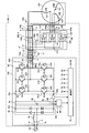
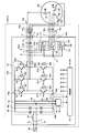
- FIG. 1 is a view showing a configuration example of a drive device for an electric motor according to a first embodiment.
- the motor drive device 400 is a power conversion device that converts AC power supplied from the AC power supply 20 into AC power of a frequency that can drive the motor 130.
- the motor drive device 400 includes an inverter board 100, a noise suppression unit 110, a relay board 200, an AC wiring 140 which is a first AC wiring, an AC wiring 150 which is a second AC wiring, and a third AC wiring.
- AC wiring 160 is provided.
- the inverter substrate 100 which is a first substrate includes an AC wiring 2, a reactor 30, a rectifier 40, a smoothing capacitor 50, an inverter 60, a control unit 70, and a detection unit 81.
- AC wiring 2, reactor 30, rectifier 40, smoothing capacitor 50, inverter 60, control unit 70 and detection unit 81 are provided on the mounting surface of inverter board 100.
- the mounting surface is a surface on which components are mounted among the plurality of end surfaces provided on the inverter substrate 100.
- An alternating current power supply 20 and one end of an alternating current wiring 2 are connected to the alternating current input terminal 1 a and the alternating current input terminal 1 b of the inverter substrate 100.
- the AC wiring 2 is a pattern wiring formed on the mounting surface of the inverter substrate 100 in order to transmit AC power from the AC power supply 20 to the rectifier 40. The other end of the AC wiring 2 is connected to the rectifier 40.
- a reactor 30 for improving the power factor is provided in the AC wiring 2.
- One end of reactor 30 is electrically connected to AC input terminal 1a.
- the other end of reactor 30 is electrically connected to rectifier 40.
- the rectifier 40 rectifies AC power supplied from the AC power supply 20.
- the rectifier 40 is a full wave rectifier circuit configured by combining four diodes.
- the rectifier 40 may be configured by combining a plurality of MOSFETs (Metal Oxide Semiconductor-Field Effect Transistors) in addition to the diodes.
- MOSFETs Metal Oxide Semiconductor-Field Effect Transistors
- the smoothing capacitor 50 smoothes the power rectified by the rectifier 40.
- One end of the smoothing capacitor 50 is connected to the DC bus 3a.
- the DC bus 3 a is a high potential side wiring provided between the rectifier 40 and the inverter 60.
- One end of the DC bus 3 a is connected to the positive output terminal 40 a of the rectifier 40.
- the other end of the DC bus 3 a is connected to the positive input terminal 60 a of the inverter 60.
- the other end of the smoothing capacitor 50 is connected to the DC bus 3b.
- the DC bus 3 b is a low potential side wiring provided between the rectifier 40 and the inverter 60.
- One end of the DC bus 3 b is connected to the negative output terminal 40 b of the rectifier 40.
- the other end of DC bus 3 b is connected to negative input terminal 60 b of inverter 60.
- the inverter 60 is a power converter that converts the power smoothed by the smoothing capacitor 50 into AC power and supplies the converted AC power to the motor 130.
- the inverter 60 includes a plurality of switching elements 611 to 616 and a plurality of free wheeling diodes 621 to 626.
- switching elements 611 to 616 are shown without distinction, they are simply referred to as switching elements.
- each of the plurality of free wheeling diodes 621 to 626 is shown without distinction, it is simply referred to as a diode.
- the switching element 611 is an element that performs a switching operation according to the drive signal Xa output from the control unit 70.
- the switching element 611 may be an element that performs a switching operation by the drive signal Xa output from the control unit 70, and is not limited to a bipolar transistor. The same applies to each of the switching elements 612 to 616.
- the switching operation is an operation of switching between the on state of the switching element 611 and the off state of the switching element 611.
- the on state is a state in which current flows between the collector and the emitter of the switching element 611, and the off state is a state in which current does not flow between the collector and the emitter of the switching element 611.
- the collector of the switching element 611 is connected to the positive side input terminal 60a.
- the emitter of switching element 611 is connected to the collector of switching element 612.
- the connection point of switching element 611 and switching element 612 is connected to output terminal 60 c of inverter 60.
- the U-phase AC wiring 63 is connected to the output terminal 60c.
- the AC wiring 63 is a pattern wiring formed on the mounting surface of the inverter substrate 100 in order to transmit AC power from the inverter 60 to the motor 130.
- the other end of the U-phase AC wiring 63 is connected to the U-phase AC output terminal 101.
- the AC output terminal 101 is a terminal provided on the mounting surface of the inverter board 100.
- One end of the U-phase AC wiring 140 is connected to the U-phase AC output terminal 101.
- the AC wiring 140 is a wiring provided between the AC output terminal 101 and the motor 130 in order to transmit AC power from the inverter 60 to the motor 130.
- the other end of the U-phase AC wiring 140 is connected to one end of the U-phase winding 131 of the motor 130.
- the switching element 612 is a switching element that performs switching operation according to the drive signal Xb output from the control unit 70.
- the emitter of the switching element 612 is connected to the negative input terminal 60b.
- the switching element 613 is a switching element that performs a switching operation according to the drive signal Ya output from the control unit 70.
- the collector of the switching element 613 is connected to the positive side input terminal 60a.
- the emitter of switching element 613 is connected to the collector of switching element 614.
- the connection point between switching element 613 and switching element 614 is connected to output terminal 60 d of inverter 60.
- One end of a V-phase AC wiring 63 is connected to the output terminal 60 d.
- the other end of the V-phase AC wiring 63 is connected to the V-phase AC output terminal 101.
- One end of a V-phase AC wiring 140 is connected to the V-phase AC output terminal 101.
- the other end of V-phase AC wiring 140 is connected to one end of V-phase winding 132 of motor 130.
- the switching element 614 is a switching element that performs a switching operation according to the drive signal Yb output from the control unit 70.
- the emitter of the switching element 614 is connected to the negative input terminal 60b.
- the switching element 615 is a switching element that performs a switching operation according to the drive signal Za output from the control unit 70.
- the collector of the switching element 615 is connected to the positive side input terminal 60a.
- the emitter of switching element 615 is connected to the collector of switching element 616.
- the connection point between switching element 615 and switching element 616 is connected to output terminal 60 e of inverter 60.
- One end of the W-phase AC wiring 63 is connected to the output terminal 60 e.
- the other end of the W-phase AC wiring 63 is connected to the W-phase AC output terminal 101.
- One end of the W-phase AC wiring 140 is connected to the W-phase AC output terminal 101.
- the other end of the W-phase AC wiring 140 is connected to one end of a W-phase winding 133 of the motor 130.
- the switching element 616 is a switching element that performs a switching operation according to the drive signal Zb output from the control unit 70.
- the emitter of the switching element 616 is connected to the negative input terminal 60b.
- each of the plurality of drive signals Xa to Zb is shown without distinction, it is simply referred to as a drive signal.
- the free wheeling diode 621 is connected in antiparallel to the switching element 611. That is, the cathode which is the cathode of the reflux diode 621 is connected to the collector of the switching element 611, and the anode which is the anode of the reflux diode 621 is connected to the emitter of the switching element 611.
- the free wheeling diode 621 may be an element having a rectifying function, and is not limited to the diode. The same applies to each of the freewheeling diodes 622 to 626.
- the free wheeling diode 622 is connected in antiparallel to the switching element 612.
- the free wheeling diode 623 is connected in antiparallel to the switching element 613.
- the free wheeling diode 624 is connected in antiparallel to the switching element 614.
- the free wheeling diode 625 is connected in antiparallel to the switching element 615.
- the free wheeling diode 626 is connected in antiparallel to the switching element 616.
- the control unit 70 generates the drive signal and the switching signal SW based on at least one of the detection value detected by the voltage detection unit 80 of the detection unit 81 and the detection value detected by the current detection unit 90 of the detection unit 81.
- Voltage detection unit 80 detects the voltage applied to DC bus 3 a and DC bus 3 b, and outputs the detected voltage detection value to control unit 70.
- Current detection unit 90 detects the current flowing through DC bus 3b, and outputs the detected current detection value to control unit 70.
- the switching signal SW is a signal that controls the operation of the connection switching unit 120. By inputting the switching signal SW to the connection switching unit 120, the connection state of the winding of the motor 130 is switched to Y connection or ⁇ connection.
- the position where the voltage detection unit 80 and the current detection unit 90 are provided may be any position that can detect information necessary for the operation of the control unit 70, and is not limited to the position shown in FIG.
- the voltage detection unit 80 may be provided at a position where the voltage divided by the resistor provided in parallel with the smoothing capacitor 50 can be detected.
- the voltage detection unit 80 thus provided converts the voltage across the smoothing capacitor 50, that is, the input-side voltage of the inverter 60 into a voltage detectable by the control unit 70 and outputs the voltage.
- the current detection unit 90 may be provided at a position where the current flowing through the AC wiring 63 can be detected. In the current detection unit 90 provided in this manner, the current flowing from the inverter 60 to the motor 130 is detected.
- the wire connection switching unit 120 is provided on the mounting surface of the relay substrate 200 which is the second substrate.
- the wire connection switching unit 120 is a switch that switches the wire connection state of the winding of the motor 130 from Y connection to ⁇ connection or from ⁇ connection to Y connection.
- the connection switching unit 120 includes a switch 121, a switch 122, and a switch 123. Each of the switch 121, the switch 122, and the switch 123 is a c-contact type relay.
- the switch 121 includes a contact a, a contact b, and a contact c.
- the contact c is connected to the contact a when energized and is connected to the contact b when deenergized.
- the contact a of the switch 121 is connected to the input terminal d through the W-phase wiring 150 b of the AC wiring 150.
- the AC wire 150 is a wire for connecting the wire connection switching unit 120 to the AC wire 140.
- the AC wiring 150 includes a wiring 150 a and a wiring 150 b.
- the wiring 150 a is a wiring provided between the AC wiring 140 and the relay substrate 200.
- the wiring 150 b is a pattern wiring formed on the mounting surface of the relay substrate 200.
- One end of the W-phase wiring 150 b is connected to the input terminal d.
- the other end of the W-phase wiring 150 b is connected to the contact a of the switch 121.
- the input terminal d is a terminal provided on the mounting surface of the relay substrate 200.
- One end of the W-phase wiring 150a is connected to the input terminal d.
- the other end of the W-phase interconnection 150 a is connected to the W-phase AC interconnection 140.
- the connection point between the other end of the W-phase wire 150 a and the W-phase AC wire 140 is indicated by symbol ⁇ .
- the position of the connection point ⁇ is between the noise suppression unit 110 and the motor 130 in the W-phase AC wiring 140.
- the contact b of the switch 121 is electrically connected to the terminal 210.
- the terminal 210 is a terminal provided on the mounting surface of the relay substrate 200, and is a terminal serving as a neutral point in the ⁇ connection.
- the contact c of the switching device 121 is connected to the input terminal Z via the U-phase wiring 160 b of the AC wiring 160.
- the AC wire 160 is a wire for connecting the wire connection switching unit 120 to the motor 130.
- the AC wiring 160 includes a wiring 160 a and a wiring 160 b.
- the wire 160 a is a wire provided between the motor 130 and the relay substrate 200.
- the wiring 160 b is a pattern wiring formed on the mounting surface of the relay substrate 200.
- One end of the U-phase wiring 160 b is connected to the contact c of the switch 121.
- the other end of the U-phase wiring 160 b is connected to the input terminal Z.
- the input terminal Z is a terminal provided on the mounting surface of the relay substrate 200.
- One end of the U-phase wiring 160 a is connected to the input terminal Z.
- the other end of the U-phase wire 160 a is connected to the other end of the U-phase winding 131 of the motor 130.
- connection state A When the switch 121 is in the connection state A, the other end of the U-phase winding 131 is electrically connected to the connection point ⁇ .
- the connection state A is a state in which the contact c is connected to the contact a.
- connection state B When the switch 121 is in the connection state B, the other end of the U-phase winding 131 is electrically connected to the contacts b of the switch 122 and the switch 123.
- the connection state B is a state in which the contact c is connected to the contact b.
- the contact a of the switch 122 is connected to the input terminal e via the U-phase wire 150 b.
- One end of the U-phase wiring 150 b is connected to the input terminal e.
- the other end of the U-phase wiring 150 b is connected to the contact a of the switch 122.
- the input terminal e is a terminal provided on the mounting surface of the relay substrate 200.
- One end of the U-phase wiring 150 a is connected to the input terminal e.
- the other end of the U-phase interconnection 150 a is connected to the U-phase AC interconnection 140.
- a connection point between the other end of the U-phase wiring 150 a and the U-phase AC wiring 140 is indicated by a symbol ⁇ .
- the position of the connection point ⁇ is between the noise suppression unit 110 and the motor 130 in the U-phase AC wiring 140.
- the contact b of the switch 122 is electrically connected to the terminal 210.
- the contact point c of the switch 122 is connected to the input terminal X via the V-phase wiring 160 b of the AC wiring 160.
- One end of the V-phase wiring 160 b is connected to the contact c of the switch 122.
- the other end of the V-phase wiring 160 b is connected to the input terminal X.
- the input terminal X is a terminal provided on the mounting surface of the relay substrate 200.
- One end of the V-phase wiring 160 a is connected to the input terminal X.
- the other end of the V-phase wiring 160 a is connected to the other end of the V-phase winding 132 of the motor 130.
- the switch 122 When the switch 122 is in the connection state A, the other end of the V-phase winding 132 is electrically connected to the connection point ⁇ . When the switch 122 is in the connection state B, the other end of the V-phase winding 132 is electrically connected to the contacts b of the switch 121 and the switch 123.
- the contact a of the switch 123 is connected to the input terminal f via the V-phase wiring 150 b.
- One end of the V-phase wiring 150 b is connected to the input terminal f.
- the other end of the V-phase wiring 150 b is connected to the contact a of the switch 123.
- the input terminal f is a terminal provided on the mounting surface of the relay substrate 200.
- One end of the V-phase wiring 150 a is connected to the input terminal f.
- the other end of the V-phase interconnection 150 a is connected to the V-phase AC interconnection 140.
- a connection point between the other end of the V-phase wiring 150a and the V-phase AC wiring 140 is indicated by a symbol ⁇ .
- the position of the connection point ⁇ is between the noise suppression unit 110 and the motor 130 in the V-phase AC wiring 140.
- the contact b of the switch 123 is electrically connected to the terminal 210.
- the contact c of the switch 123 is connected to the input terminal Y via the W-phase wiring 160 b of the AC wiring 160.
- One end of the W-phase wiring 160 b is connected to the contact c of the switch 123.
- the other end of the W-phase wiring 160 b is connected to the input terminal Y.
- the input terminal Y is a terminal provided on the mounting surface of the relay substrate 200.
- One end of a W-phase wire 160 a is connected to the input terminal Y.
- the other end of the W-phase wire 160 a is connected to the other end of the W-phase winding 133 of the motor 130.
- the switch 123 When the switch 123 is in the connection state A, the other end of the W-phase winding 133 is electrically connected to the connection point ⁇ . When the switch 123 is in the connection state B, the other end of the W-phase winding 133 is electrically connected to the contacts b of the switch 121 and the switch 122.
- the noise suppression unit 110 is provided to the three AC wirings 140 of the U phase, the V phase, and the W phase. Specifically, the noise suppression unit 110 is provided in the wiring from the AC output terminal 101 to the connection points ⁇ , ⁇ , and ⁇ among the AC wiring 140 extending from the AC output terminal 101 to the motor 130.
- the noise suppression unit 110 can be exemplified by a cylindrical magnetic body, an inductor, or a bypass capacitor.
- a ferrite core is used for the magnetic body.
- the ferrite core may be provided to the AC wiring 140 or may be provided to a power signal line or an earth wire provided adjacent to the AC wiring 140.
- the power signal line is a signal transmission wiring extending from the AC output terminal 101 to the motor 130.
- the signal transmission wiring is used to transmit rotational position detection information of the motor.
- the earth wire is a grounding wire extending from the AC output terminal 101 to the motor 130.
- a ferrite bead, a choke coil or a reactor is used for the inductor.
- As the bypass capacitor an across-the-line capacitor or a line bypass capacitor is used.
- the noise suppression unit 110 may be configured by one of a magnetic body, an inductor and a bypass capacitor, or may be configured by combining a plurality of magnetic bodies, an inductor and a bypass capacitor.
- the motor 130 includes a U-phase winding 131, a V-phase winding 132 and a W-phase winding 133.
- U-phase winding 131, V-phase winding 132 and W-phase winding 133 can be switched to Y connection or ⁇ connection depending on the connection state of switches 121 to 123. By switching the wire connection state of the motor 130 to Y connection or ⁇ connection, high output drive and high efficiency drive of the motor 130 are possible.
- the U-phase winding 131, the V-phase winding 132, and the W-phase winding 133 are simply referred to as windings when they are shown without distinction.
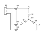
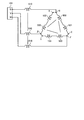
- FIG. 2 is a view showing a winding whose connection state is Y connection by the drive device for an electric motor according to the first embodiment.
- the wire connection state of the winding of the motor 130 is Y connection as shown in FIG.
- the inductance 500 shown in FIG. 2 is an inductance component formed in the AC wiring 140 at the time of Y connection when the noise suppression unit 110 of FIG. 1 is a magnetic body.
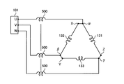
- FIG. 3 is a first view showing a winding whose connection state is ⁇ connection by the motor drive device according to the first embodiment.
- the wire connection state of the winding of the motor 130 is ⁇ connection as shown in FIG.
- the inductance 500 shown in FIG. 3 is an inductance component formed in the AC wiring 140 at the time of ⁇ connection when the noise suppression unit 110 in FIG. 1 is a magnetic body.
- the line voltage of the motor 130 in Y connection is VY, and the current flowing in Y connection is defined as IY. Further, the line voltage of the motor 130 at the time of ⁇ connection is V ⁇ , and the current flowing at the time of ⁇ connection is defined as I ⁇ .
- a brushless DC motor is widely used as the motor 130.
- a permanent magnet is used for the rotor of the brushless DC motor.
- the back electromotive voltage of the motor 130 increases as the rotational speed of the rotor increases, and the voltage value necessary to drive the motor 130 increases.
- the back electromotive force is an electromotive voltage that causes a current to flow in the direction opposite to the direction of the current flowing when the motor 130 is driven by the power generation operation of the motor 130.
- the voltage required for driving the motor 130 at the same rotational speed as the ⁇ -connected motor 130 increases compared to when the ⁇ -connected motor 130 is driven. Do. Then, as the voltage required to drive the motor 130 increases, the back electromotive force also increases. In order to suppress the increase of the back electromotive force, it is necessary to reduce the magnetic force of the permanent magnet or to unroll the stator winding. When this measure is taken, the motor 130 and the inverter 60 are A decrease in efficiency is inevitable due to the increased current flow.
- the voltage necessary for driving the motor 130 is 1 / ⁇ 3 times the voltage at the Y connection by switching from Y connection to ⁇ connection. Become. Therefore, the operation of the motor 130 can be continued without taking the above measures.
- the air conditioner in recent years rotates the motor 130 until the set temperature is approached when the difference between the set temperature at the start of operation and the room temperature is larger than a specific value.
- the air conditioner reduces the rotational speed of the motor 130 when the set temperature and the room temperature substantially match.
- the general agreement means that the temperature difference between the set temperature and the room temperature is, for example, within 0.5 ° C.
- the ratio of the low speed operation time to the entire operation time is larger than the ratio of the high speed operation time to the entire operation time.
- the low speed operation time is a time during which the motor 130 operates at a low rotational speed lower than a specific rotational speed.
- the high speed operation time is a time during which the motor 130 is operated at a high rotational speed higher than a specific rotational speed. Therefore, in the case where the motor drive device 400 drives the motor 130 at a low rotation speed, the drive voltage is low, and thus the Y connection can be made to reduce the current, and the motor 130 is driven at a high rotation speed. Use the ⁇ connection.
- the value of the current flowing through motor 130 can not only be 1 / ⁇ 3 times that of ⁇ connection, but also the winding wire at Y connection The diameter and the number of turns can be set to be optimum at a low rotational speed.
- the value of the current flowing through the motor 130 can be reduced compared to the motor 130 configured to drive the entire rotation speed range by Y connection. Therefore, the loss which generate
- the drive device 400 of the motor sets the wire connection state of the motor 130 to ⁇ connection.
- the motor 130 can be driven at a voltage 1 / ⁇ 3 times the voltage of the motor 130 set so as to optimize the wire diameter and the number of turns of the winding at the time of Y connection. Therefore, the motor 130 can be driven in the entire rotation number region without unwinding the winding, and the entire rotation number region can be driven without using flux-weakening control to increase the current value more than necessary.
- the motor drive device 400 since the motor drive device 400 according to the first embodiment includes the wire connection switching mechanism that switches the wire connection state to Y connection or ⁇ wire connection, the motor does not have the wire connection switching mechanism compared to the motor drive device.
- the number of AC wires between the drive device 400 and the motor 130 is tripled. That is, in the drive device for the motor not provided with the wire connection switching mechanism, the drive device for the motor and the motor are connected by one AC wiring, while in the drive device 400 for the motor according to the first embodiment, the AC Wiring 140, AC wiring 150 and AC wiring 160 are required. As the number of AC wiring increases, the number of mounting points of the EMI suppression component increases. Therefore, the EMI countermeasure structure becomes larger and more complicated.
- the motor drive device 400 when the motor drive device 400 is installed in the outdoor unit of the air conditioner, if the EMI countermeasure structure is enlarged, there is a possibility that the mounting place of the motor drive device 400 on the casing of the outdoor unit can not be secured. is there. Therefore, it is necessary to take measures such as enlarging the casing of the outdoor unit or reviewing the arrangement of components inside the outdoor unit.
- the casing of the outdoor unit is an electrical item box provided inside the outdoor unit, or a casing forming an outer shell of the outdoor unit.
- the increase in EMI countermeasure cost and the loss due to the EMI countermeasure part may increase due to the increase in the number of attachment points of the EMI countermeasure part.
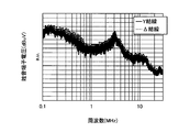
- FIG. 4 is a diagram showing noise terminal voltage characteristics in the case where the noise suppression unit is not provided between the inverter and the motor shown in FIG.
- the vertical axis of FIG. 4 represents the noise terminal voltage
- the horizontal axis of FIG. 4 represents the frequency.
- the solid line is the noise terminal voltage characteristic at Y connection.
- the broken line is the noise terminal voltage characteristic at the time of ⁇ connection.
- the noise terminal voltage characteristics represent frequency characteristics or noise levels.
- the noise terminal voltage characteristic is changed by changing the length of.
- the configuration example of the motor drive device 400 according to the first embodiment is not limited to the illustrated example, and therefore the noise terminal voltage characteristics are not limited to those shown in FIG.
- noise due to circulating current flowing between the three-phase windings of the motor 130 is generated in the noise terminal voltage characteristic at the time of the ⁇ connection.
- the circulating current flowing between the three-phase windings of motor 130 is a current circulating between U-phase winding 131, V-phase winding 132 and W-phase winding 133.
- the noise terminal voltage characteristic at the time of ⁇ connection the noise terminal voltage tends to increase in the frequency band from 200 [kHz] to 2 [MHz] compared to the noise terminal voltage characteristic at the Y connection. It is in.
- the motor drive device 400 having a connection switching mechanism of Y connection and ⁇ connection, it is essential to study measures against noise components caused by circulating current at ⁇ connection.
- motor drive device 400 reduces noise suppression unit 110 between connection points ⁇ , ⁇ , ⁇ and AC output terminal 101 as shown in FIG. Is provided.
- noise suppression unit 110 By providing the noise suppression unit 110 between the connection points ⁇ , ⁇ , and ⁇ and the AC output terminal 101, EMI propagated between the inverter 60 and the motor 130 in any connection state of ⁇ connection and Y connection. Noise is suppressed.
- the switching noise generated by driving the inverter 60 between the inverter 60 and the motor 130 becomes a dominant factor of the EMI noise.
- the noise suppression unit 110 between the connection points ⁇ , ⁇ , and ⁇ and the AC output terminal 101, switching noise generated by driving the inverter 60 can be effectively suppressed.
- the AC wiring 140 is provided with the noise suppression unit 110. Therefore, compared with the case where the EMI suppression component is attached to each of the AC wiring 140, the AC wiring 150, and the AC wiring 160, the number of attachment places of the EMI suppression component can be reduced. Therefore, the EMI countermeasure structure is simplified, and the EMI countermeasure structure can be realized while suppressing an increase in size of the motor drive device 400 and an increase in manufacturing cost. In addition, since the number of attachment points of the EMI countermeasure components can be reduced, the frequency of the characteristic deterioration and failure occurrence of the EMI countermeasure components can be reduced.
- the EMI countermeasure structure by simplifying the EMI countermeasure structure, it becomes easy to secure the mounting place of the drive device 400 of the motor to the casing of the outdoor unit, enlarge the casing of the outdoor unit, or arrange components inside the outdoor unit. It becomes unnecessary to take measures such as reviewing. Therefore, the enlargement of the outdoor unit or the increase in manufacturing cost can be suppressed. Further, since the number of attachment points of the EMI countermeasure components can be reduced, the increase in loss due to the EMI countermeasure components described above can be suppressed, and the motor 130 can be driven with high efficiency and high output. In addition, since the number of attachment points for the EMI countermeasure components can be reduced, an increase in the area for attaching the EMI countermeasure components to the casing of the outdoor unit is suppressed.
- the length of the wiring wound on the EMI countermeasure components can be shortened, and an increase in the wiring length can be suppressed.
- a ferrite core is used as the noise suppression unit 110
- a wire is wound multiple times on the ferrite core.
- the wiring corresponds to the AC wiring 140.
- the length of wiring wound on the ferrite core becomes short, so that the material cost of the wiring and the cost of the wiring operation are reduced.
- the length of the wire wound around the ferrite core is shortened, the impedance of the wire is reduced, and the motor 130 can be driven with high efficiency and high output.
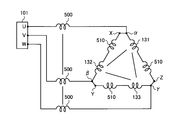
- FIG. 5 is a second view showing a winding whose connection state is ⁇ connection by the drive device for an electric motor according to the first embodiment.
- an inductance 500 and an inductance 510 which are formed on the AC wiring 140 by the noise suppression unit 110 made of a magnetic material are shown.
- the inductance 510 is an inductance formed by the added noise suppression unit 110 when the noise suppression unit 110 is additionally provided in the wiring between the connection points ⁇ , ⁇ , and ⁇ and the contact point a.
- an inductance 510 is formed between the connection points ⁇ , ⁇ , and ⁇ and the windings of the motor 130 at the time of ⁇ connection. Noise due to circulating current flowing between the lines is suppressed.
- the noise suppression portion 110 may be additionally provided in the wiring extending from the terminal 210 of the relay substrate 200 to the contact b, or in the wiring 160b extending from the contact c to the input terminals X, Y, Z.
- the noise suppression unit 110 may be additionally provided.
- an inductance by the added noise suppressing portion is formed in the wiring 160 b in the ⁇ connection. Therefore, the noise component resulting from the circulating current flowing between the three-phase windings is suppressed.
- the EMI noise suppression effect can be enhanced by the inductance obtained by adding these inductances.
- the AC wiring 140 may be directly connected to the AC wiring 63 which is a pattern wiring of the inverter substrate 100. That is, the AC wiring 140 may be connected to the AC wiring 63 without passing through the AC output terminal 101. Even in the case of such wiring, in the first embodiment, it is assumed that one noise suppression unit 110 is provided between the inverter 60 and the connection points ⁇ , ⁇ , and ⁇ . By providing the noise suppressing portion 110 in the AC wiring 140, it is not necessary to provide the EMI countermeasure structure in the pattern wiring on the inverter substrate 100. Therefore, the pattern wiring length can be shortened and the wiring structure on the inverter substrate 100 can be simplified as compared with the case where the EMI countermeasure structure is provided in the pattern wiring.
- the noise suppression part 110 when providing the noise suppression part 110 in alternating current wiring 140, it is desirable to provide the noise suppression part 110 near the inverter board
- the winding may be switched from Y connection to Y connection, and a mechanism capable of switching the winding from ⁇ connection to ⁇ connection may be provided.
- a switch is provided in the middle of the winding, and a mechanism for adjusting the number of turns of the three-phase winding by operating the switch according to the required load, and providing two or more windings in each phase
- a mechanism is conceivable which adjusts the number of turns of the three-phase winding by connecting each of two or more windings in accordance with the required load.
- the configuration is not limited as long as the effect of switching from Y connection to Y connection and the effect of switching from ⁇ connection to ⁇ connection can be obtained.
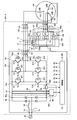
- FIG. 6 is a view showing a configuration example of a drive device for an electric motor according to a second embodiment.
- Drive device 400-2 of the motor according to the second embodiment includes relay substrate 200-2 instead of relay substrate 200.
- the AC wiring 140 includes an AC wiring 140a, an AC wiring 140b, and an AC wiring 140c.
- the other configuration is the same as or equivalent to the configuration of the first embodiment, and the same or equivalent components are denoted by the same reference numerals and redundant description will be omitted.
- the connection switching unit 120 and the AC wiring 140b are provided on the relay substrate 200-2.
- the AC wiring 140b is a pattern wiring formed on the mounting surface of the relay substrate 200-2. One end of the AC wiring 140b is connected to one end of the AC wiring 140a.
- the AC wiring 140a is an inter-substrate wiring provided between the inverter substrate 100 and the relay substrate 200-2.
- a connection point between the U-phase AC wiring 140 b and the U-phase AC wiring 140 a is a connection point ⁇ ′.
- a connection point between the V-phase AC wiring 140 b and the V-phase AC wiring 140 a is indicated by a symbol ⁇ ′.
- a connection point between the W-phase AC wiring 140 b and the W-phase AC wiring 140 a is indicated by a symbol ⁇ ′.
- the other end of the U-phase AC wiring 140 a is connected to the U-phase AC output terminal 101.
- the other end of the V-phase AC wiring 140 a is connected to the V-phase AC output terminal 101.
- the other end of the W-phase AC wiring 140 a is connected to the W-phase AC output terminal 101.
- the noise suppression unit 110 is provided in the AC wiring 140 a.
- the other end of the AC wiring 140b is connected to one end of the AC wiring 140c.
- the AC wiring 140c is a motor wiring provided between the relay substrate 200-2 and the winding of the motor 130.
- a connection point between the U-phase AC wiring 140 b and the U-phase AC wiring 140 c is indicated by a symbol ⁇ .
- a connection point between the V-phase AC wiring 140 b and the V-phase AC wiring 140 c is indicated by a symbol ⁇ .
- a connection point between the W-phase AC wiring 140 b and the W-phase AC wiring 140 c is indicated by a symbol ⁇ .
- the other end of the U-phase AC wiring 140 c is connected to one end of the U-phase winding 131.
- the other end of V-phase AC wiring 140 c is connected to one end of V-phase winding 132.
- the other end of the W-phase AC wiring 140 c is connected to one end of the W-phase winding 133.
- One end of the W-phase wiring 150 b of the AC wiring 150 is connected to the W-phase AC wiring 140 b.
- the other end of the W-phase wiring 150 b is connected to the contact a of the switch 121.
- the contact a of the switch 121 is connected to the W-phase AC wiring 140 b via the W-phase wiring 150 b.
- One end of the U-phase wiring 150 b of the AC wiring 150 is connected to the U-phase AC wiring 140 b.
- the other end of the U-phase wiring 150 b is connected to the contact a of the switch 122.
- the contact a of the switch 122 is connected to the U-phase AC wiring 140 b through the U-phase wiring 150 b.
- V-phase wiring 150 b of the AC wiring 150 is connected to the V-phase AC wiring 140 b.
- the other end of the V-phase wiring 150 b is connected to the contact a of the switch 123.
- the contact a of the switch 123 is connected to the V-phase AC wiring 140 b through the V-phase wiring 150 b.
- motor 130 is connected to inverter board 100 via AC wiring 140b on relay board 200-2. Since the length of the AC wiring 140 of the first embodiment is longer than the length of the AC wiring 140c of the second embodiment, a terminal block for relaying the AC wiring 140 to the outside of the inverter substrate 100 in the first embodiment. Or caulking may be required.
- the terminal block is a terminal block including a primary side terminal to which a wire extending from the inverter substrate 100 is connected and a secondary terminal to which a wire extending from the motor 130 is connected.
- the caulking is a metal sleeve into which the end of the wire extending from the inverter substrate 100 and the end of the wire extending from the motor 130 are inserted.
- the inverter substrate 100 and the motor 130 can be electrically connected without using a terminal block or caulking. . Therefore, in the second embodiment, in addition to the effects of the first embodiment, the effect that the wiring structure can be simplified can be obtained. Further, in the second embodiment, since the wiring length of the AC wiring 140 is shorter than that of the first embodiment, the motor driving device 400-2 can be reduced in weight by the reduction of the wiring length of the AC wiring 140.
- the noise suppressing portion 110 is provided in the AC wiring 140a, the inverter 60 and the electric motor 130 are also connected in either the ⁇ connection or the Y connection as in the first embodiment.
- EMI noise that propagates between Further, by providing the noise suppressing portion 110 in the AC wiring 140a, it is possible to effectively suppress the switching noise generated by driving the inverter 60. Further, by providing the noise suppressing portion 110 in the AC wiring 140a, the number of attachment places of the EMI countermeasure components may be smaller than in the case where the EMI countermeasure components are attached to the AC wiring 140 and the AC wiring 160 respectively. Therefore, the EMI countermeasure structure is simplified, and the EMI countermeasure structure can be realized while suppressing the increase in size and manufacturing cost of the motor drive device 400-2.
- the noise suppression unit 110 may be additionally provided in the wiring between the connection points ⁇ , ⁇ , ⁇ and the contact point a.
- Wiring between the connection points ⁇ , ⁇ , ⁇ and the contact point a may be an AC wiring 140 b or a wiring 150 b.
- an inductance due to the noise suppressing portion added is formed in at least one of the AC wiring 140b and the wiring 150b in the ⁇ connection. Therefore, the noise component resulting from the circulating current flowing between the three-phase windings is suppressed.
- the noise suppressing portion 110 may be additionally provided in the wiring extending from the terminal 210 to the contact b of the relay substrate 200-2, or the wiring extending from the contact c to the input terminals X, Y, Z
- the noise suppression unit 110 may be additionally provided at 160 b.
- an inductance due to the added noise suppression portion is formed in the wiring 160 b in the ⁇ connection. Therefore, the noise component resulting from the circulating current flowing between the three-phase windings is suppressed.
- the EMI noise suppression effect can be enhanced by the inductance obtained by adding up these inductances.
- the AC wiring 140 a may be directly connected to the AC wiring 63 which is a pattern wiring of the inverter substrate 100. That is, the AC wiring 140 a may be connected to the AC wiring 63 without passing through the AC output terminal 101. Even in the case of such wiring, in the second embodiment, it is assumed that one noise suppressing portion 110 is provided in the AC wiring 140a. By providing the noise suppressing portion 110 in the AC wiring 140 a, it is not necessary to provide the EMI countermeasure structure in the pattern wiring on the inverter substrate 100. Therefore, the pattern wiring length can be shortened and the wiring structure on the inverter substrate 100 can be simplified as compared with the case where the EMI countermeasure structure is provided in the pattern wiring.
- the distance from the noise suppression unit 110 to the relay substrate 200-2 on the AC wiring 140a is desirably longer than the distance from the noise suppression unit 110 to the inverter 60 on the AC wiring 140a.
- the noise suppression unit 110 can be kept away from the motor 130. By moving the noise suppression unit 110 away from the motor 130, the progress of the characteristic deterioration of the noise suppression unit 110 can be delayed, and the frequency of occurrence of failure of the noise suppression unit 110 can be reduced.
- the winding can be switched from Y connection to Y connection as in the first embodiment, and the winding can be switched from ⁇ connection to ⁇ connection. Possible mechanisms may be provided.
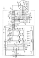
- FIG. 7 is a diagram showing a configuration example of a drive device for an electric motor according to a third embodiment.
- Drive device 400-3 of the motor according to the third embodiment includes power substrate 300 which is a first substrate, instead of inverter substrate 100 and relay substrate 200.
- the power substrate 300 is provided with components provided on the inverter substrate 100 and components provided on the relay substrate 200.
- the AC wiring 140 includes an AC wiring 140 d and an AC wiring 140 e.
- the other configuration is the same as or equivalent to the configuration of the first embodiment, and the same or equivalent components are denoted by the same reference numerals and redundant description will be omitted.
- the AC wiring 140 d is a pattern wiring formed on the mounting surface of the power substrate 300.
- One end of the U-phase AC wiring 140 d is connected to one end of the output terminal 60 c of the inverter 60.
- One end of the V-phase AC wiring 140 d is connected to one end of the output terminal 60 d of the inverter 60.
- One end of the W-phase AC wiring 140 d is connected to one end of the output terminal 60 e of the inverter 60.
- the noise suppression unit 110 is provided in the AC wiring 140 d.
- the other end of the U-phase AC wiring 140d is connected to the U-phase AC output terminal 101-3.
- the AC output terminal 101-3 is a terminal provided on the mounting surface of the power substrate 300.
- the other end of the V-phase AC wiring 140d is connected to the V-phase AC output terminal 101-3.
- the other end of the W-phase AC wiring 140d is connected to the W-phase AC output terminal 101-3.
- the AC output terminal 101-3 is connected to the motor 130 via the AC wiring 140e.
- the AC wiring 140 e is a wiring provided between the power substrate 300 and the winding of the motor 130.
- One end of the U-phase AC wiring 140 e is connected to the U-phase AC output terminal 101-3.
- the other end of the U-phase AC wiring 140 e is connected to one end of the U-phase winding 131.
- One end of the V-phase AC wiring 140 e is connected to the V-phase AC output terminal 101-3.
- the other end of V-phase AC wiring 140 e is connected to one end of V-phase winding 132.
- One end of the W-phase AC wiring 140 e is connected to the W-phase AC output terminal 101-3.
- the other end of the W-phase AC wiring 140 e is connected to one end of the W-phase winding 133.
- the contact a of the switch 121 is connected to the W-phase AC wiring 140 d via the W-phase wiring 150 c of the AC wiring 150.
- the wiring 150 c is a pattern wiring formed on the mounting surface of the power substrate 300.
- One end of the W-phase interconnection 150c is connected to the W-phase AC interconnection 140d.
- the other end of the W-phase wiring 150 c is connected to the contact a of the switch 121.
- a connection point between the W-phase wiring 150c and the W-phase AC wiring 140d is indicated by a symbol ⁇ .
- the contact a of the switch 122 is connected to the U-phase AC wiring 140 d via the wiring 150 c of the U-phase AC wiring 150.
- One end of the U-phase interconnection 150c is connected to the U-phase AC interconnection 140d.
- the other end of the U-phase wiring 150 c is connected to the contact a of the switch 122.
- a connection point between the U-phase interconnection 150c and the U-phase AC interconnection 140d is indicated by a symbol ⁇ .
- the contact a of the switch 123 is connected to the V-phase AC wiring 140 d via the V-phase wiring 150 c.
- One end of the V-phase interconnection 150c is connected to the V-phase AC interconnection 140d.
- the other end of the V-phase wiring 150 c is connected to the contact a of the switch 123.
- a connection point between the V-phase wiring 150c and the V-phase AC wiring 140d is indicated by a symbol ⁇ .
- the contact b of the switch 121 is connected to the terminal 211.
- the terminal 211 is a terminal provided on the power substrate 300 and is a terminal serving as a neutral point in the ⁇ connection.
- the contact b of the switch 122 is connected to the terminal 211.
- the contact b of the switch 123 is connected to the terminal 211.
- the contact c of the switch 121 is connected to the input terminal Z ′ via the U-phase wiring 160 c of the AC wiring 160.
- the AC wiring 160 includes a wiring 160 a and a wiring 160 c.
- One end of the U-phase wiring 160 a is connected to the input terminal Z ′.
- the other end of the U-phase wire 160 a is connected to the other end of the U-phase winding 131 of the motor 130.
- the wiring 160 c is a pattern wiring formed on the mounting surface of the power substrate 300.
- One end of the U-phase wiring 160 c is connected to the contact c of the switch 121.
- the other end of the U-phase wiring 160c is connected to the input terminal Z '.
- the input terminal Z ′ is a terminal provided on the mounting surface of the power substrate 300.
- the contact c of the switch 122 is connected to the input terminal X ′ via the V-phase wiring 160 c of the AC wiring 160.
- One end of the V-phase wiring 160 c is connected to the contact c of the switch 122.
- the other end of the V phase wiring 160c is connected to the input terminal X '.
- the input terminal X ′ is a terminal provided on the mounting surface of the power substrate 300.
- One end of the V-phase wiring 160 a is connected to the input terminal X ′.
- the other end of the V-phase wiring 160 a is connected to the other end of the V-phase winding 132 of the motor 130.
- the contact point c of the switch 123 is connected to the input terminal Y ′ via the W-phase wiring 160 c of the AC wiring 160.
- One end of the W-phase wiring 160 c is connected to the contact c of the switch 123.
- the other end of the W-phase interconnection 160c is connected to the input terminal Y '.
- the input terminal Y ′ is a terminal provided on the mounting surface of the power substrate 300.
- One end of the W-phase wiring 160 a is connected to the input terminal Y ′.
- the other end of the W-phase wire 160 a is connected to the other end of the W-phase winding 133 of the motor 130.
- the motor 130 is connected to the inverter 60 via the AC wiring 140 d of the power substrate 300, the AC wiring 140 e, and the AC wiring 160.
- the number of substrates to be used can be reduced compared to the first embodiment.
- the wiring 150a is unnecessary, the number of wirings for connecting the inverter substrate 100 and the relay substrate 200 is reduced.
- the power substrate 300 and the motor 130 can be electrically connected without using the above-described terminal block or caulking. Can connect to Therefore, in the third embodiment, in addition to the effects of the first embodiment, an effect that the wiring structure can be simplified can be obtained. Further, since the amount of use of the AC wiring 140e is reduced, the manufacturing cost of the motor driving device 400-3 can be reduced. Further, since the wiring length of the AC wiring 140 e is shortened, the inductance component of the AC wiring 140 e is reduced, and the EMI noise can be reduced.
- the noise suppressing portion 110 is provided in the AC wiring 140 d, the inverter 60 and the motor 130 are connected in either the ⁇ connection or the Y connection as in the first embodiment.
- EMI noise that propagates between Further, by providing the noise suppressing portion 110 in the AC wiring 140d, it is possible to effectively suppress the switching noise generated by driving the inverter 60. Further, by providing the noise suppressing portion 110 in the AC wiring 140d, the number of attachment places of the EMI countermeasure components can be reduced as compared with the case where the EMI countermeasure components are attached to each of the AC wiring 140d and the AC wiring 160. Therefore, the EMI countermeasure structure is simplified, and the EMI countermeasure structure can be realized while suppressing an increase in size and manufacturing cost of the motor drive device 400-3.
- the noise suppression unit 110 may be additionally provided in the wiring 150 c between the connection points ⁇ , ⁇ , ⁇ and the contact point a. As described above, by additionally providing the noise suppressing portion 110, an inductance by the added noise suppressing portion is formed in the wiring 150c in the ⁇ connection. Therefore, the noise component resulting from the circulating current flowing between the three-phase windings is suppressed.
- the noise suppressing portion 110 may be additionally provided in the wiring extending from the terminal 211 to the contact b, or in the wiring 160c extending from the contact c to the input terminal X ′, Y ′, Z ′.
- the noise suppression unit 110 may be additionally provided.
- an inductance due to the added noise suppression portion is formed in the wiring 160 c in the ⁇ connection. Therefore, the noise component resulting from the circulating current flowing between the three-phase windings is suppressed.
- the EMI noise suppression effect can be enhanced by the inductance obtained by adding up these inductances.
- U-phase AC wiring 140e may be connected to output terminal 60c of inverter 60 instead of U-phase AC wiring 140d.
- V-phase AC wiring 140d instead of the V-phase AC wiring 140d, the V-phase AC wiring 140e may be connected to the output terminal 60d of the inverter 60.
- W-phase AC wiring 140d instead of the W-phase AC wiring 140d, the W-phase AC wiring 140e may be connected to the output terminal 60e of the inverter 60.
- the distance from the noise suppression unit 110 to the AC output terminal 101-3 on the AC wiring 140 d is desirably longer than the distance from the noise suppression unit 110 to the inverter 60 on the AC wiring 140 d.
- the noise suppression unit 110 can be kept away from the motor 130.
- the heat and vibration transmitted from the motor 130 are less likely to be transmitted to the noise suppression unit 110. Therefore, the progress of the characteristic deterioration of the noise suppression unit 110 can be delayed, and the frequency of occurrence of failure of the noise suppression unit 110 can be reduced.
- the winding can be switched from Y connection to Y connection as in the first embodiment, and the winding can be switched from ⁇ connection to ⁇ connection. Possible mechanisms may be provided.
- FIG. 8 is a diagram showing an example of a configuration of a drive device for an electric motor according to a fourth embodiment.
- the noise suppressing portion is connected to the wiring from the connection points ⁇ , ⁇ , ⁇ to the motor 130. 110 are provided.
- the other configuration is the same as or equivalent to the configuration of the first embodiment, and the same or equivalent components are denoted by the same reference numerals and redundant description will be omitted.
- FIG. 9 is a view showing a winding whose connection state is Y connection by the drive device for an electric motor according to the fourth embodiment.
- the inductance 500 shown in FIG. 9 is an alternating current from the connection points ⁇ , ⁇ , ⁇ to the electric motor 130 in Y connection when the noise suppression unit 110 shown in FIG. 8 is a magnetic body that suppresses EMI noise. It is an inductance component formed in the wiring 140. The inductance 500 suppresses the EMI noise generated between the inverter 60 and the motor 130 during Y connection.
- FIG. 10 is a first diagram showing a winding whose connection state is ⁇ connection by the drive device for an electric motor according to the fourth embodiment.
- the inductance 500 shown in FIG. 10 is formed between the connection points ⁇ , ⁇ , and ⁇ and each winding at the time of ⁇ connection when the noise suppression unit 110 shown in FIG. 8 is a magnetic body that suppresses EMI noise. Inductance component.
- the inductance 500 suppresses the EMI noise generated between the inverter 60 and the motor 130, and further suppresses the noise caused by the circulating current flowing between the three-phase windings of the motor 130.
- the EMI noise propagating between inverter 60 and motor 130 is suppressed in Y connection, and the EMI noise transmitted between inverter 60 and motor 130 is suppressed in ⁇ connection, and further. Noise due to circulating current is suppressed. Therefore, in the fourth embodiment, EMI noise can be suppressed more than in the first to third embodiments.
- the noise suppressing portion 110 may be additionally provided in the AC wiring 140 from the AC output terminal 101 to the connection points ⁇ , ⁇ , ⁇ .
- the inductance 500 and the inductance due to the added noise suppression part are formed in the AC wiring 140b.
- the EMI noise can be further suppressed compared to the case where the noise suppression unit 110 is provided only in the AC wiring 140.
- FIG. 11 is a second view showing a winding whose connection state is ⁇ connection by the drive device for an electric motor according to the fourth embodiment.
- an inductance 500 and an inductance 510 are shown.
- the inductance 500 is the same as the inductance 500 shown in FIG. That is, it is an inductance component formed between the connection points ⁇ , ⁇ , ⁇ and each winding at the time of ⁇ connection by the noise suppression unit 110 shown in FIG.
- the inductance 510 is an inductance formed by the added noise suppression unit 110 when the noise suppression unit 110 is additionally provided in the wiring from the AC output terminal 101 to the connection points ⁇ , ⁇ , and ⁇ .
- an inductance 500 is formed between the connection points ⁇ , ⁇ , ⁇ and each winding of the motor 130 in the ⁇ connection, and an inductance 510 is further formed in the AC wiring 140. It is formed. Therefore, the inductance 500 suppresses the EMI noise propagating between the inverter 60 and the motor 130 and the EMI noise resulting from the circulating current between the three-phase windings of the motor 130. Furthermore, the inductance 510 suppresses EMI noise propagating between the inverter 60 and the motor 130.
- the noise suppression unit 110 may be additionally provided in the wiring 150 a between the connection points ⁇ , ⁇ , ⁇ and the contact point a.
- the noise suppression unit 110 by additionally providing the noise suppression unit 110, the inductance 500 described above and the noise suppression added to the wiring between the connection points ⁇ , ⁇ and ⁇ and the windings of the motor 130 are added at the time of ⁇ connection. An inductance is formed by the part. Therefore, the EMI noise propagating between the inverter 60 and the motor 130 and the EMI noise resulting from the circulating current between the three phase windings of the motor 130 are suppressed.
- the noise suppression portion 110 may be additionally provided in the wiring extending from the terminal 210 to the contact b of the relay substrate 200, or to the wiring 160b extending from the contact c to the input terminals X, Y, Z.
- the noise suppression unit 110 may be additionally provided.
- an inductance 500 is formed in the wiring between the connection points ⁇ , ⁇ , ⁇ and each winding of the motor 130, and further in the wiring 160b.
- An inductance is formed by the added noise suppressor. Therefore, an inductance is formed by adding the inductance 500 and the inductance of the added noise suppression unit 110. Therefore, the EMI noise can be further suppressed as compared with the case where the noise suppression unit 110 is provided only in the AC wiring 140.
- the noise suppression portion 110 in this way, in the case of ⁇ connection, as shown in FIG. 11, the wiring between the connection points ⁇ , ⁇ , ⁇ and each winding of the motor 130 is inductance 500 and An inductance 510 is formed. Therefore, the EMI noise propagating between the inverter 60 and the motor 130 and the EMI noise resulting from the circulating current between the three phase windings of the motor 130 are suppressed.
- the alternating current wiring 140 may be directly connected to an alternating current wiring 63 which is a pattern wiring of the inverter substrate 100 shown in FIG. That is, the AC wiring 140 may be connected to the AC wiring 63 without passing through the AC output terminal 101. Even in the case of such wiring, in the fourth embodiment, it is assumed that one noise suppression unit 110 is provided between the wiring from the connection points ⁇ , ⁇ , and ⁇ to the motor 130. By providing the noise suppressing portion 110 in the AC wiring 140, it is not necessary to provide the EMI countermeasure structure in the pattern wiring of the inverter substrate 100. Therefore, the pattern wiring length can be shortened and the wiring structure on the inverter substrate 100 can be simplified as compared with the case where the EMI countermeasure structure is provided in the pattern wiring.
- connection point (alpha), (beta), (gamma) it is desirable to provide the noise suppression part 110 near connection point (alpha), (beta), (gamma). That is, it is desirable that the distance from the noise suppression unit 110 to the motor 130 on the AC wiring 140 be longer than the distance from the noise suppression unit 110 on the AC wiring 140 to the connection points ⁇ , ⁇ , and ⁇ . Thereby, the noise suppression unit 110 can be kept away from the motor 130. By moving the noise suppression unit 110 away from the motor 130, the progress of the characteristic deterioration of the noise suppression unit 110 can be delayed, and the frequency of occurrence of failure of the noise suppression unit 110 can be reduced.
- the winding can be switched from Y connection to Y connection, and from ⁇ connection to ⁇ connection.
- a switchable mechanism may be provided.
- FIG. 12 is a diagram showing a configuration example of a drive device for an electric motor according to a fifth embodiment.
- the noise suppression unit 110 is provided in the AC wiring 140 c extending from the relay substrate 200-2 to the motor 130.
- the other configuration is the same as or equivalent to the configuration of the second embodiment, and the same or equivalent components are denoted by the same reference numerals and redundant description will be omitted.
- the inverter substrate 100 and the motor 130 can be electrically connected without using the above-described terminal block or caulking. It can connect. Therefore, in the fifth embodiment, in addition to the effects of the fourth embodiment, the effect that the wiring structure can be simplified can be obtained.
- noise suppressing portion 110 is provided in AC wiring 140c, noise connecting portion 110 is connected between connection points ⁇ , ⁇ , ⁇ and each winding of electric motor 130 in Y connection. An inductance is formed. Therefore, the EMI noise propagating between the connection points ⁇ , ⁇ , ⁇ and the windings of the motor 130 is suppressed.
- an inductance by the noise suppression unit 110 is formed between the connection points ⁇ , ⁇ , ⁇ and each winding of the motor 130. In this case, the inductance suppresses the EMI noise propagating between the connection points ⁇ , ⁇ , ⁇ and the motor 130, and further suppresses the EMI noise caused by the circulating current between the three phase windings of the motor 130. .
- the switching noise generated by driving the inverter 60 between the inverter 60 and the motor 130 becomes a dominant factor of the EMI noise.
- the noise suppression unit 110 between the connection points ⁇ , ⁇ , and ⁇ and the motor 130, EMI noise generated by driving the inverter 60 can be effectively suppressed.
- the noise suppressing portion 110 is provided in the AC wiring 140 c. Therefore, compared with the case where the EMI suppression component is attached to each of the AC wiring 140 c and the AC wiring 160, the number of attachment places of the EMI suppression component can be reduced. Therefore, the EMI countermeasure structure is simplified, and the EMI countermeasure structure can be realized while suppressing an increase in size and manufacturing cost of the motor drive device 400-5. In addition, since the number of attachment points of the EMI countermeasure components can be reduced, the frequency of the characteristic deterioration and failure occurrence of the EMI countermeasure components can be reduced.
- the EMI countermeasure structure by simplifying the EMI countermeasure structure, it becomes easy to secure the mounting place of the motor drive device 400-5 to the casing of the outdoor unit, and the casing of the outdoor unit is enlarged or the inside of the outdoor unit It becomes unnecessary to take measures such as reviewing the arrangement of parts, so it is possible to suppress an increase in size of the outdoor unit or an increase in manufacturing cost.
- the number of attachment points of the EMI countermeasure components can be reduced, an increase in loss due to the EMI countermeasure components can be suppressed, and the motor 130 can be driven with high efficiency and high output.
- the wiring length of the AC wiring 140 since the wiring length of the AC wiring 140 is shorter than that of the fourth embodiment, it is possible to reduce the weight of the motor driving device 400-5 as the wiring length of the AC wiring 140 becomes shorter.
- the noise suppression unit 110 may be additionally provided to the AC wiring 140a.
- an inductance 500 shown in FIG. 9 is formed in the AC wiring 140c at the time of Y connection. Furthermore, an inductance due to the added noise suppression unit is formed in the AC wiring 140a. Therefore, the EMI noise transmitted between the AC output terminal 101 and the motor 130 is suppressed by the inductance obtained by adding the inductance 500 and the inductance by the added noise suppression unit.
- an inductance 500 is formed in the wiring between the connection points ⁇ , ⁇ , ⁇ and each winding of the motor 130 as shown in FIG.
- an inductance 510 is formed in the wiring between the AC output terminal 101 and the motor 130. Therefore, the inductance 500 suppresses the EMI noise propagating between the inverter 60 and the motor 130 and the EMI noise resulting from the circulating current between the three-phase windings of the motor 130. Furthermore, the inductance 510 suppresses EMI noise propagating between the inverter 60 and the motor 130.
- the noise suppression unit 110 may be additionally provided in the wiring between the connection points ⁇ , ⁇ , ⁇ and the contact point a.
- Wiring between the connection points ⁇ , ⁇ , ⁇ and the contact point a may be an AC wiring 140 b or a wiring 150 b.
- the inductance 500 described above is formed at the time of ⁇ connection, and an inductance due to the added noise suppression portion is formed in at least one of the AC wiring 140b and the wiring 150b.
- Ru The inductance which added these inductances suppresses the EMI noise propagated between the inverter 60 and the motor 130 and the EMI noise caused by the circulating current between the three-phase windings of the motor 130.
- the noise suppressing portion 110 may be additionally provided in the wiring extending from the terminal 210 to the contact b of the relay substrate 200-2, or the wiring extending from the contact c to the input terminals X, Y, Z
- the noise suppression unit 110 may be additionally provided at 160 b.
- an inductance 510 is formed in the wiring between the connection points ⁇ , ⁇ , ⁇ and each winding of the motor 130, and the noise added to the wiring 160b.
- An inductance is formed by the suppressor.
- an inductance 500 shown in FIG. 11 is formed in the wiring between connection points ⁇ , ⁇ and ⁇ and each winding of motor 130, and between terminal 210 and input terminals X, Y and Z.
- an inductance due to the added noise suppression portion is formed in the wiring between the connection points ⁇ , ⁇ , ⁇ and the windings of the motor 130.
- the EMI noise transmitted between the inverter 60 and the motor 130 is suppressed by the inductance obtained by adding the inductance 500 and the inductance by the added noise suppression portion, and the circulation flowing between the three-phase windings of the motor 130 is further suppressed. Noise due to current is suppressed.
- the AC wiring 140 a may be directly connected to the AC wiring 63 of the inverter substrate 100. That is, the AC wiring 140 a may be connected to the AC wiring 63 without passing through the AC output terminal 101. Even in the case of such wiring, in the fifth embodiment, it is assumed that one noise suppressing portion 110 is provided in the AC wiring 140c. By providing the noise suppressing portion 110 in the AC wiring 140c, it is not necessary to provide the EMI countermeasure structure in the pattern wiring on the inverter substrate 100. Therefore, the pattern wiring length can be shortened and the wiring structure on the inverter substrate 100 can be simplified as compared with the case where the EMI countermeasure structure is provided in the pattern wiring.
- the noise suppression unit 110 When the noise suppression unit 110 is provided in the AC wiring 140c, it is desirable that the noise suppression unit 110 be provided closer to the relay substrate 200-2. That is, it is desirable that the distance from the noise suppression unit 110 to the motor 130 on the AC wiring 140c be longer than the distance from the noise suppression unit 110 to the relay substrate 200-2 on the AC wiring 140c. Thereby, the noise suppression unit 110 can be kept away from the motor 130. By moving the noise suppression unit 110 away from the motor 130, the progress of the characteristic deterioration of the noise suppression unit 110 can be delayed, and the frequency of occurrence of failure of the noise suppression unit 110 can be reduced.
- the winding can be switched from Y connection to Y connection, and from ⁇ connection to ⁇ connection.
- a switchable mechanism may be provided.
- FIG. 13 is a view showing an example of the configuration of a drive device for an electric motor according to a sixth embodiment.
- noise suppressor 110 is provided on AC wiring 140 e extending from power substrate 300 to motor 130.
- the noise suppressing portion 110 is provided in the AC wiring 140 e, but the noise suppressing portion 110 may be provided in the AC wiring 160 instead of the AC wiring 140 e.
- the other configuration is the same as or equivalent to the configuration of the third embodiment, and the same or equivalent components are denoted by the same reference numerals and redundant description will be omitted.
- the number of substrates to be used can be reduced as compared with the fourth embodiment. Further, in the sixth embodiment, since the wiring 150a is unnecessary, the number of wirings for connecting the inverter substrate 100 and the relay substrate 200 is reduced. Further, in the sixth embodiment, since the length of the AC wiring 140 e is shorter than that of the AC wiring 140 of the fourth embodiment, the power substrate 300 and the motor 130 can be electrically connected without using the above-described terminal block or caulking. Can connect to Therefore, in the sixth embodiment, in addition to the effect of the fourth embodiment, an effect that the wiring structure can be simplified can be obtained. Further, since the amount of use of the AC wiring 140e is reduced, the manufacturing cost of the motor drive device 400-6 can be reduced. Further, since the wiring length of the AC wiring 140 e is shortened, the inductance component of the AC wiring 140 e is reduced, and the EMI noise can be reduced.
- noise suppressing portion 110 is provided in AC wiring 140 e or AC wiring 160, between the connection points ⁇ , ⁇ , ⁇ and each winding of electric motor 130 in the Y connection, An inductance 500 shown in FIG. 9 is formed. Therefore, the EMI noise transmitted between the inverter 60 and the motor 130 is suppressed.
- an inductance is formed between the inverter 60 and each winding of the motor 130 by the noise suppression unit 110. Therefore, the EMI noise propagating between inverter 60 and motor 130 is suppressed, and the EMI noise resulting from the circulating current flowing between the three phase windings of motor 130 is further suppressed.
- the switching noise generated by driving the inverter 60 becomes a dominant factor of the EMI noise between the inverter 60 and the motor 130.
- the noise suppression unit 110 in the AC wiring 140 e or the AC wiring 160, it is possible to effectively suppress the EMI noise generated by driving the inverter 60.
- the noise suppressing portion 110 is provided in the AC wiring 140 e or the AC wiring 160, the EMI countermeasure mounting part is attached as compared to the case where the EMI countermeasure mounting part is attached to each of the AC wiring 140 e There are few places. Therefore, the EMI countermeasure structure is simplified, and the EMI countermeasure structure can be realized while suppressing the increase in size and manufacturing cost of the motor drive device 400-6. In addition, since the number of attachment points of the EMI countermeasure components can be reduced, the frequency of the characteristic deterioration and failure occurrence of the EMI countermeasure components can be reduced.
- the EMI countermeasure structure by simplifying the EMI countermeasure structure, it becomes easy to secure the mounting place of the drive device 400-6 for the motor to the casing of the outdoor unit, enlarge the casing of the outdoor unit, or parts inside the outdoor unit It becomes unnecessary to take measures such as reviewing the arrangement, and therefore, it is possible to suppress an increase in size of the outdoor unit or an increase in manufacturing cost.
- the number of attachment points of the EMI countermeasure components can be reduced, an increase in loss due to the EMI countermeasure components can be suppressed, and the motor 130 can be driven with high efficiency and high output.
- the noise suppression unit 110 may be additionally provided to the AC wiring 140 d.
- the noise suppression unit 110 in the case of Y connection, in the wiring between the AC output terminal 101-3 and the motor 130, the inductance 500 shown in FIG. 9 and the noise suppression unit added thereto are provided. An inductance is formed. Therefore, the EMI noise is suppressed by the inductance obtained by adding the inductance 500 and the inductance of the added noise suppression unit.
- an inductance 500 shown in FIG. 11 is formed between connection points ⁇ , ⁇ and ⁇ and the windings of motor 130, and an inductance 510 shown in FIG.
- the inductance 500 suppresses the EMI noise propagating between the inverter 60 and the motor 130 and the EMI noise resulting from the circulating current between the three-phase windings of the motor 130. Further, the inductance 510 suppresses the EMI noise propagating between the inverter 60 and the motor 130.
- the noise suppression unit 110 may be additionally provided on the wiring 150c between the connection points ⁇ , ⁇ , and ⁇ on the power substrate 300 and the contact a.
- an inductance 500 shown in FIG. 10 is formed in the wiring between the connection points ⁇ , ⁇ , ⁇ and the windings of the motor 130 in the ⁇ connection, and further, An inductance is formed by the added noise suppressor. Therefore, the EMI component propagated between the inverter 60 and the motor 130 and the noise component caused by the circulating current flowing between the three-phase windings by the inductance obtained by adding the inductance 500 and the inductance by the added noise suppression unit. And can be suppressed.
- the noise suppression portion 110 may be additionally provided in the wiring extending from the terminal 211 to the contact b, or in the wiring 160c extending from the contact c to the input terminal X ′, Y ′, Z ′.
- the noise suppression unit 110 may be additionally provided.
- an inductance 500 shown in FIG. 9 is formed between the inverter 60 and each winding of the motor 130 in Y connection, and an inductance by the noise suppression portion further added is provided. Is formed. Therefore, the EMI noise can be suppressed by the inductance obtained by adding the inductance 500 and the inductance of the added noise suppression unit.
- U-phase AC wiring 140 e may be connected to the output terminal 60 c instead of U-phase AC wiring 140 d.
- the V-phase AC wiring 140e may be connected to the output terminal 60d.
- the W-phase AC wiring 140e may be connected to the output terminal 60e.
- the noise suppression part 110 when providing the noise suppression part 110 in the alternating current wiring 140e or the alternating current wiring 160, it is desirable to provide the noise suppression part 110 near the inverter 60.
- the distance from the noise suppressing portion 110 to the motor 130 on the AC wiring 140 e is the distance from the noise suppressing portion 110 to the power substrate 300 on the AC wiring 140 e. It is desirable to make it longer.
- the noise suppression unit 110 is provided in the AC wiring 160, the distance from the noise suppression unit 110 to the motor 130 on the AC wiring 160 is longer than the distance from the noise suppression unit 110 on the AC wiring 160 to the power substrate 300. It is desirable to do. Thereby, the noise suppression unit 110 can be kept away from the motor 130.
- the noise suppression unit 110 By moving the noise suppression unit 110 away from the motor 130, the heat and vibration transmitted from the motor 130 are less likely to be transmitted to the noise suppression unit 110. Therefore, the progress of the characteristic deterioration of the noise suppression unit 110 can be delayed, and the frequency of occurrence of failure of the noise suppression unit 110 can be reduced.
- the winding can be switched from Y connection to Y connection, and from ⁇ connection to ⁇ connection.
- a switchable mechanism may be provided.
- FIG. 14 is a view showing a configuration example of an air conditioner according to a seventh embodiment.
- the air conditioner 700 includes an indoor unit 701 and an outdoor unit 702.
- the outdoor unit 702 includes a casing 702a, a motor 130, a blower fan 702d, a machine room 702f, a partition plate 702g, a compressor 702c, and an electrical component box 800.
- the casing 702 a is a casing that constitutes an outer shell of the outdoor unit 702.
- the air blowing chamber 702e is provided between the air outlet on the front side of the casing 702a and a heat exchanger (not shown). Heat exchangers are provided on the side and back of the casing 702a.
- the compressor 702c is disposed inside the machine room 702f.
- the machine room 702f is a rainproof structure separated from the air blowing room 702e by a partition plate 702g.
- the compressor 702c can be exemplified by a rotary compressor, a scroll compressor or a hermetic compressor.
- a refrigerant compressor (not shown) and an electric motor 130 are provided inside the compressor 702c.
- the rotating shaft of the motor 130 is connected to the refrigerant compressor.
- the electrical component box 800 is disposed on the machine room 702 f side and is disposed between the top plate 702 n and the compressor 702 c.
- the electrical component box 800 is a quadrangular housing formed by processing a metal which is an example of a noncombustible material.
- Electric appliance box 800 is provided with drive device 400 for the electric motor according to the first embodiment.
- Electric product box 800 may be provided with any of motor drive devices 400-2 to 400-6 of the second to sixth embodiments in place of motor drive device 400.
- each of the drive devices 400 to 400-6 of the motor is simply referred to as a drive device of the motor.
- the drive device of the motor drives the motor 130, whereby the refrigerant is compressed in the refrigerant compression unit connected to the rotation shaft of the motor 130.
- the air conditioner 700 according to Embodiment 7 can switch between the ⁇ connection and the Y connection by providing a drive device for an electric motor, so that high power operation and high efficiency operation of the air conditioner 700 can be compatible.
- the EMI countermeasure structure or the EMI countermeasure structure is simplified by providing the drive device of the motor, the place for attaching the drive device of the motor to the electrical item box 800 can be obtained without increasing the size of the electrical item box 800. It becomes easy to secure. Therefore, the enlargement of the outdoor unit 702 can be suppressed.
- the configuration shown in the above embodiment shows an example of the contents of the present invention, and can be combined with another known technique, and one of the configurations is possible within the scope of the present invention. Parts can be omitted or changed.
Landscapes
- Engineering & Computer Science (AREA)
- Power Engineering (AREA)
- Physics & Mathematics (AREA)
- Mechanical Engineering (AREA)
- Thermal Sciences (AREA)
- General Engineering & Computer Science (AREA)
- Control Of Ac Motors In General (AREA)
- Inverter Devices (AREA)
Abstract
Description
図1は実施の形態1に係る電動機の駆動装置の構成例を示す図である。電動機の駆動装置400は、交流電源20から供給される交流電力を、電動機130を駆動可能な周波数の交流電力に変換する電力変換装置である。電動機の駆動装置400は、インバータ基板100、ノイズ抑制部110、リレー基板200、第1の交流配線である交流配線140、第2の交流配線である交流配線150、及び第3の交流配線である交流配線160を備える。
図6は実施の形態2に係る電動機の駆動装置の構成例を示す図である。実施の形態2に係る電動機の駆動装置400-2は、リレー基板200の代わりにリレー基板200-2を備える。交流配線140は、交流配線140a、交流配線140b及び交流配線140cを備える。その他の構成については、実施の形態1の構成と同一又は同等であり、同一又は同等の構成部には同一の符号を付して、重複する説明は省略する。
図7は実施の形態3に係る電動機の駆動装置の構成例を示す図である。実施の形態3に係る電動機の駆動装置400-3は、インバータ基板100及びリレー基板200の代わりに、第1の基板であるパワー基板300を備える。パワー基板300には、インバータ基板100に設けられる部品とリレー基板200に設けられる部品とが設けられる。交流配線140は、交流配線140d及び交流配線140eを備える。その他の構成については、実施の形態1の構成と同一又は同等であり、同一又は同等の構成部には同一の符号を付して、重複する説明は省略する。
図8は実施の形態4に係る電動機の駆動装置の構成例を示す図である。実施の形態4に係る電動機の駆動装置400-4では、交流出力端子101から電動機130まで伸びる交流配線140の内、接続点α,β,γから電動機130までの間の配線に、ノイズ抑制部110が設けられる。その他の構成については、実施の形態1の構成と同一又は同等であり、同一又は同等の構成部には同一の符号を付して、重複する説明は省略する。
図12は実施の形態5に係る電動機の駆動装置の構成例を示す図である。実施の形態5に係る電動機の駆動装置400-5では、リレー基板200-2から電動機130まで伸びる交流配線140cに、ノイズ抑制部110が設けられる。その他の構成については、実施の形態2の構成と同一又は同等であり、同一又は同等の構成部には同一の符号を付して、重複する説明は省略する。
図13は実施の形態6に係る電動機の駆動装置の構成例を示す図である。実施の形態6に係る電動機の駆動装置400-6では、パワー基板300から電動機130まで伸びる交流配線140eにノイズ抑制部110が設けられる。なお、実施の形態6では、交流配線140eにノイズ抑制部110が設けられているが、ノイズ抑制部110は、交流配線140eの代わりに交流配線160に設けてもよい。その他の構成については、実施の形態3の構成と同一又は同等であり、同一又は同等の構成部には同一の符号を付して、重複する説明は省略する。
図14は実施の形態7に係る空気調和機の構成例を示す図である。空気調和機700は、室内機701及び室外機702を備える。室外機702は、ケーシング702a、電動機130、送風ファン702d、機械室702f、仕切り板702g、圧縮機702c及び電気品箱800を備える。
Claims (8)
- 巻線を有する電動機に交流電力を供給するインバータと、
前記インバータが設けられる第1の基板と、
前記巻線の結線状態を、Y結線からΔ結線に切替え又はΔ結線からY結線に切替える結線切替部と、
前記インバータと前記結線切替部とを制御する制御部と、
一端が前記インバータと電気的に接続され、他端が前記巻線の一端と電気的に接続される第1の交流配線と、
一端が前記第1の交流配線と電気的に接続され、他端が前記結線切替部の一端と電気的に接続される第2の交流配線と、
一端が前記結線切替部の他端と電気的に接続され、他端が前記巻線の他端と電気的に接続される第3の交流配線と、
少なくとも前記第1の交流配線に設けられ、前記第1の交流配線で発生するノイズを抑制するノイズ抑制部と
を備えることを特徴とする電動機の駆動装置。 - 前記結線切替部は、第2の基板に設けられ、
前記第1の交流配線は、
前記第2の基板に形成されるパターン配線と、
一端が前記インバータと電気的に接続され、他端が前記パターン配線の一端と電気的に接続される基板間配線と、
一端が前記パターン配線の他端と電気的に接続され、他端が前記巻線の一端と電気的に接続される電動機配線と
を備え、
前記第2の交流配線は、前記パターン配線と電気的に接続されることを特徴とする請求項1に記載の電動機の駆動装置。 - 前記第1の基板には、前記インバータと前記結線切替部とが設けられることを特徴とする請求項1に記載の電動機の駆動装置。
- 前記ノイズ抑制部は、前記第1の交流配線と前記第2の交流配線との接続点から前記巻線までの間に設けられることを特徴とする請求項1から3の何れか一項に記載の電動機の駆動装置。
- 前記ノイズ抑制部は、前記第1の交流配線及び前記第2の交流配線に設けられることを特徴とする請求項1から4の何れか一項に記載の電動機の駆動装置。
- 前記ノイズ抑制部は、前記第1の交流配線及び前記第3の交流配線に設けられることを特徴とする請求項1から4の何れか一項に記載の電動機の駆動装置。
- 前記ノイズ抑制部は、前記第1の交流配線、前記第2の交流配線及び前記第3の交流配線に設けられることを特徴とする請求項1から4の何れか一項に記載の電動機の駆動装置。
- 請求項1から7の何れか一項に記載の電動機の駆動装置を備えたことを特徴とする空気調和機。
Priority Applications (5)
| Application Number | Priority Date | Filing Date | Title |
|---|---|---|---|
| JP2019535486A JP6821031B2 (ja) | 2017-08-08 | 2017-08-08 | 電動機の駆動装置及び空気調和機 |
| CN201780093433.8A CN110945776B (zh) | 2017-08-08 | 2017-08-08 | 电动机的驱动装置和空调机 |
| EP17921011.7A EP3667897A4 (en) | 2017-08-08 | 2017-08-08 | ELECTRIC MOTOR AND AIR CONDITIONER DRIVE DEVICE |
| PCT/JP2017/028828 WO2019030836A1 (ja) | 2017-08-08 | 2017-08-08 | 電動機の駆動装置及び空気調和機 |
| US16/614,234 US10978981B2 (en) | 2017-08-08 | 2017-08-08 | Drive apparatus for electric motor and air conditioner |
Applications Claiming Priority (1)
| Application Number | Priority Date | Filing Date | Title |
|---|---|---|---|
| PCT/JP2017/028828 WO2019030836A1 (ja) | 2017-08-08 | 2017-08-08 | 電動機の駆動装置及び空気調和機 |
Publications (1)
| Publication Number | Publication Date |
|---|---|
| WO2019030836A1 true WO2019030836A1 (ja) | 2019-02-14 |
Family
ID=65272093
Family Applications (1)
| Application Number | Title | Priority Date | Filing Date |
|---|---|---|---|
| PCT/JP2017/028828 Ceased WO2019030836A1 (ja) | 2017-08-08 | 2017-08-08 | 電動機の駆動装置及び空気調和機 |
Country Status (5)
| Country | Link |
|---|---|
| US (1) | US10978981B2 (ja) |
| EP (1) | EP3667897A4 (ja) |
| JP (1) | JP6821031B2 (ja) |
| CN (1) | CN110945776B (ja) |
| WO (1) | WO2019030836A1 (ja) |
Cited By (1)
| Publication number | Priority date | Publication date | Assignee | Title |
|---|---|---|---|---|
| JP2020156293A (ja) * | 2019-03-22 | 2020-09-24 | 日本電産株式会社 | モータ、およびインバータ装置 |
Families Citing this family (3)
| Publication number | Priority date | Publication date | Assignee | Title |
|---|---|---|---|---|
| DE112018007961T5 (de) * | 2018-09-07 | 2021-06-02 | Mitsubishi Electric Corporation | Elektromotoransteuerungsvorrichtung und Ausseneinheit einer Klimaanlage |
| JP7069400B2 (ja) * | 2019-03-06 | 2022-05-17 | 三菱電機株式会社 | 電動機駆動装置及び空気調和機 |
| WO2020261317A1 (ja) * | 2019-06-24 | 2020-12-30 | 三菱電機株式会社 | 空気調和装置および空気調和システム |
Citations (4)
| Publication number | Priority date | Publication date | Assignee | Title |
|---|---|---|---|---|
| JPH09191689A (ja) | 1996-01-05 | 1997-07-22 | Fanuc Ltd | 交流電動機のリアクトル挿入方法 |
| JP2006246674A (ja) | 2005-03-07 | 2006-09-14 | Mitsubishi Electric Corp | 電動機駆動装置、電動機駆動方法及び圧縮機 |
| JP2008228513A (ja) * | 2007-03-15 | 2008-09-25 | Mitsubishi Electric Corp | 電動機駆動装置および電動機駆動方法並びに冷凍空調装置 |
| JP2011199984A (ja) * | 2010-03-18 | 2011-10-06 | Tokyo Institute Of Technology | モータ駆動システム |
Family Cites Families (16)
| Publication number | Priority date | Publication date | Assignee | Title |
|---|---|---|---|---|
| JPS6032596A (ja) * | 1983-07-30 | 1985-02-19 | Mitsubishi Electric Corp | 極数変換電動機の制御方式 |
| JP2932080B2 (ja) | 1990-03-13 | 1999-08-09 | 株式会社安川電機 | インバータの制御方式 |
| IT1313385B1 (it) * | 1999-05-27 | 2002-07-23 | St Microelectronics Srl | Metodo e dispositivo per pilotare con lo stesso circuito integratomotori brushless a fasi indipendenti o a fasi precollegate a stella |
| EP1284045A1 (en) * | 2000-05-23 | 2003-02-19 | Vestas Wind System A/S | Variable speed wind turbine having a matrix converter |
| JP2005160263A (ja) * | 2003-11-28 | 2005-06-16 | Nippon Reliance Kk | Ac可変速駆動装置 |
| JP4515115B2 (ja) * | 2004-03-01 | 2010-07-28 | 三菱電機株式会社 | 同期誘導電動機の保護装置、圧縮機、冷凍サイクル装置 |
| JP2005287157A (ja) * | 2004-03-29 | 2005-10-13 | Mitsubishi Electric Corp | ノイズフィルタ及び空気調和機 |
| KR100688185B1 (ko) * | 2004-05-28 | 2007-03-02 | 엘지전자 주식회사 | 속도 가변형 모터 |
| JP2008067534A (ja) | 2006-09-08 | 2008-03-21 | Yaskawa Electric Corp | フィルタ装置および電力変換装置 |
| JP5213890B2 (ja) * | 2010-02-23 | 2013-06-19 | 三菱電機株式会社 | モータ駆動装置及び圧縮機及び冷凍サイクル装置及び洗濯機及び洗濯乾燥機及び送風機 |
| US9543887B2 (en) * | 2010-10-15 | 2017-01-10 | Mitsubishi Electric Corporation | Heat pump device, heat pump system, and method for controlling three-phase inverter |
| US9746216B2 (en) * | 2012-06-29 | 2017-08-29 | Mitsubishi Electric Corporation | Heat pump device, heat pump system, air conditioner, and freezer |
| JP2014045539A (ja) * | 2012-08-24 | 2014-03-13 | Denso Corp | スタータ用ノイズ抑制装置 |
| US9344018B2 (en) * | 2013-08-23 | 2016-05-17 | Ld Design Electronics Ab | Method for making a motor quieter |
| JP6173231B2 (ja) * | 2014-02-05 | 2017-08-02 | 三菱電機株式会社 | 電力変換装置および空気調和装置 |
| US10320220B2 (en) * | 2017-08-23 | 2019-06-11 | Ford Global Technologies, Llc | Configurable hybrid drive systems |
-
2017
- 2017-08-08 US US16/614,234 patent/US10978981B2/en active Active
- 2017-08-08 WO PCT/JP2017/028828 patent/WO2019030836A1/ja not_active Ceased
- 2017-08-08 EP EP17921011.7A patent/EP3667897A4/en not_active Withdrawn
- 2017-08-08 CN CN201780093433.8A patent/CN110945776B/zh active Active
- 2017-08-08 JP JP2019535486A patent/JP6821031B2/ja active Active
Patent Citations (4)
| Publication number | Priority date | Publication date | Assignee | Title |
|---|---|---|---|---|
| JPH09191689A (ja) | 1996-01-05 | 1997-07-22 | Fanuc Ltd | 交流電動機のリアクトル挿入方法 |
| JP2006246674A (ja) | 2005-03-07 | 2006-09-14 | Mitsubishi Electric Corp | 電動機駆動装置、電動機駆動方法及び圧縮機 |
| JP2008228513A (ja) * | 2007-03-15 | 2008-09-25 | Mitsubishi Electric Corp | 電動機駆動装置および電動機駆動方法並びに冷凍空調装置 |
| JP2011199984A (ja) * | 2010-03-18 | 2011-10-06 | Tokyo Institute Of Technology | モータ駆動システム |
Non-Patent Citations (1)
| Title |
|---|
| See also references of EP3667897A4 |
Cited By (2)
| Publication number | Priority date | Publication date | Assignee | Title |
|---|---|---|---|---|
| JP2020156293A (ja) * | 2019-03-22 | 2020-09-24 | 日本電産株式会社 | モータ、およびインバータ装置 |
| JP7078002B2 (ja) | 2019-03-22 | 2022-05-31 | 日本電産株式会社 | モータ、およびインバータ装置 |
Also Published As
| Publication number | Publication date |
|---|---|
| CN110945776B (zh) | 2023-04-18 |
| CN110945776A (zh) | 2020-03-31 |
| US10978981B2 (en) | 2021-04-13 |
| JPWO2019030836A1 (ja) | 2019-12-12 |
| EP3667897A4 (en) | 2020-10-07 |
| US20200186072A1 (en) | 2020-06-11 |
| EP3667897A1 (en) | 2020-06-17 |
| JP6821031B2 (ja) | 2021-01-27 |
Similar Documents
| Publication | Publication Date | Title |
|---|---|---|
| JP4260110B2 (ja) | フィルタ装置 | |
| US11965684B2 (en) | Inverter module and electric compressor comprising same | |
| JP6821031B2 (ja) | 電動機の駆動装置及び空気調和機 | |
| JP7394196B2 (ja) | 電気回路体及び冷凍サイクル装置 | |
| EP3876401B1 (en) | Electronic control assembly and electric appliance | |
| JPWO2020208825A1 (ja) | 電力変換装置および空気調和機 | |
| JP4363497B1 (ja) | フィルタ回路実装ユニット及び電源ユニット | |
| US11601047B2 (en) | Electrical control assembly and electrical device | |
| CN206743047U (zh) | 空调器及空调器中变频压缩机的电磁干扰抑制电路 | |
| EP3591829B1 (en) | Power conversion device | |
| JP2012124985A (ja) | 冷凍装置 | |
| JP7678262B2 (ja) | モータ | |
| JP2018204435A (ja) | 電動圧縮機 | |
| WO2013014769A1 (ja) | インバータ装置および電源装置 | |
| KR20200007417A (ko) | 전력 변환 장치 및 이를 구비하는 홈 어플라이언스 | |
| CN121399846A (zh) | 电机驱动系统及热源装置 | |
| JP2007228747A (ja) | インバータ装置 | |
| WO2019026257A1 (ja) | 電動機システムおよび電動機システムを備える室外機 | |
| JP6491761B2 (ja) | 電力変換回路 | |
| WO2023228641A1 (ja) | インバータ装置及びそれを備えた電動圧縮機 | |
| JP2006262633A (ja) | コンバータ装置 | |
| CN110957947A (zh) | 电机的驱动控制电路、电机、家电设备 | |
| JPWO2013014769A1 (ja) | インバータ装置および電源装置 |
Legal Events
| Date | Code | Title | Description |
|---|---|---|---|
| 121 | Ep: the epo has been informed by wipo that ep was designated in this application |
Ref document number: 17921011 Country of ref document: EP Kind code of ref document: A1 |
|
| ENP | Entry into the national phase |
Ref document number: 2019535486 Country of ref document: JP Kind code of ref document: A |
|
| NENP | Non-entry into the national phase |
Ref country code: DE |
|
| ENP | Entry into the national phase |
Ref document number: 2017921011 Country of ref document: EP Effective date: 20200309 |
|
| WWW | Wipo information: withdrawn in national office |
Ref document number: 2017921011 Country of ref document: EP |