WO2019030866A1 - プロペラファン、送風装置、及び冷凍サイクル装置 - Google Patents
プロペラファン、送風装置、及び冷凍サイクル装置 Download PDFInfo
- Publication number
- WO2019030866A1 WO2019030866A1 PCT/JP2017/028957 JP2017028957W WO2019030866A1 WO 2019030866 A1 WO2019030866 A1 WO 2019030866A1 JP 2017028957 W JP2017028957 W JP 2017028957W WO 2019030866 A1 WO2019030866 A1 WO 2019030866A1
- Authority
- WO
- WIPO (PCT)
- Prior art keywords
- propeller fan
- wing
- connection point
- trailing edge
- rear edge
- Prior art date
- Legal status (The legal status is an assumption and is not a legal conclusion. Google has not performed a legal analysis and makes no representation as to the accuracy of the status listed.)
- Ceased
Links
Images


Classifications
-
- F—MECHANICAL ENGINEERING; LIGHTING; HEATING; WEAPONS; BLASTING
- F04—POSITIVE - DISPLACEMENT MACHINES FOR LIQUIDS; PUMPS FOR LIQUIDS OR ELASTIC FLUIDS
- F04D—NON-POSITIVE-DISPLACEMENT PUMPS
- F04D29/00—Details, component parts, or accessories
- F04D29/26—Rotors specially for elastic fluids
- F04D29/32—Rotors specially for elastic fluids for axial flow pumps
- F04D29/38—Blades
- F04D29/384—Blades characterised by form
-
- F—MECHANICAL ENGINEERING; LIGHTING; HEATING; WEAPONS; BLASTING
- F25—REFRIGERATION OR COOLING; COMBINED HEATING AND REFRIGERATION SYSTEMS; HEAT PUMP SYSTEMS; MANUFACTURE OR STORAGE OF ICE; LIQUEFACTION SOLIDIFICATION OF GASES
- F25D—REFRIGERATORS; COLD ROOMS; ICE-BOXES; COOLING OR FREEZING APPARATUS NOT OTHERWISE PROVIDED FOR
- F25D17/00—Arrangements for circulating cooling fluids; Arrangements for circulating gas, e.g. air, within refrigerated spaces
- F25D17/04—Arrangements for circulating cooling fluids; Arrangements for circulating gas, e.g. air, within refrigerated spaces for circulating air, e.g. by convection
- F25D17/06—Arrangements for circulating cooling fluids; Arrangements for circulating gas, e.g. air, within refrigerated spaces for circulating air, e.g. by convection by forced circulation
- F25D17/067—Evaporator fan units
-
- F—MECHANICAL ENGINEERING; LIGHTING; HEATING; WEAPONS; BLASTING
- F05—INDEXING SCHEMES RELATING TO ENGINES OR PUMPS IN VARIOUS SUBCLASSES OF CLASSES F01-F04
- F05D—INDEXING SCHEME FOR ASPECTS RELATING TO NON-POSITIVE-DISPLACEMENT MACHINES OR ENGINES, GAS-TURBINES OR JET-PROPULSION PLANTS
- F05D2240/00—Components
- F05D2240/20—Rotors
- F05D2240/30—Characteristics of rotor blades, i.e. of any element transforming dynamic fluid energy to or from rotational energy and being attached to a rotor
- F05D2240/303—Characteristics of rotor blades, i.e. of any element transforming dynamic fluid energy to or from rotational energy and being attached to a rotor related to the leading edge of a rotor blade
-
- F—MECHANICAL ENGINEERING; LIGHTING; HEATING; WEAPONS; BLASTING
- F05—INDEXING SCHEMES RELATING TO ENGINES OR PUMPS IN VARIOUS SUBCLASSES OF CLASSES F01-F04
- F05D—INDEXING SCHEME FOR ASPECTS RELATING TO NON-POSITIVE-DISPLACEMENT MACHINES OR ENGINES, GAS-TURBINES OR JET-PROPULSION PLANTS
- F05D2240/00—Components
- F05D2240/20—Rotors
- F05D2240/30—Characteristics of rotor blades, i.e. of any element transforming dynamic fluid energy to or from rotational energy and being attached to a rotor
- F05D2240/304—Characteristics of rotor blades, i.e. of any element transforming dynamic fluid energy to or from rotational energy and being attached to a rotor related to the trailing edge of a rotor blade
-
- F—MECHANICAL ENGINEERING; LIGHTING; HEATING; WEAPONS; BLASTING
- F25—REFRIGERATION OR COOLING; COMBINED HEATING AND REFRIGERATION SYSTEMS; HEAT PUMP SYSTEMS; MANUFACTURE OR STORAGE OF ICE; LIQUEFACTION SOLIDIFICATION OF GASES
- F25D—REFRIGERATORS; COLD ROOMS; ICE-BOXES; COOLING OR FREEZING APPARATUS NOT OTHERWISE PROVIDED FOR
- F25D2317/00—Details or arrangements for circulating cooling fluids; Details or arrangements for circulating gas, e.g. air, within refrigerated spaces, not provided for in other groups of this subclass
- F25D2317/06—Details or arrangements for circulating cooling fluids; Details or arrangements for circulating gas, e.g. air, within refrigerated spaces, not provided for in other groups of this subclass with forced air circulation
- F25D2317/068—Details or arrangements for circulating cooling fluids; Details or arrangements for circulating gas, e.g. air, within refrigerated spaces, not provided for in other groups of this subclass with forced air circulation characterised by the fans
- F25D2317/0681—Details thereof
Definitions
- the present invention relates to a propeller fan provided with a wing, a blower and a refrigeration cycle apparatus provided with the propeller fan.
- the present invention has been made to solve the problems as described above, and a propeller fan capable of reducing vortices generated at the trailing edge of a wing, a blower having the propeller fan, and a refrigeration cycle apparatus It is what you get.
- a propeller fan includes a shaft portion provided on a rotating shaft, and a wing provided on an outer peripheral side of the shaft portion, the wing being a trailing edge formed on the reverse side in the rotational direction.
- the rear edge portion includes a first rear edge portion located at the innermost side and a second rear edge portion adjacent to the outer peripheral side of the first rear edge portion;
- a point on the innermost circumferential side of the rear edge is defined as a first connection point, a connection point between the first rear edge and the second rear edge is defined as a second connection point, and the rotation axis and the rotation axis
- the second connection point is located on the forward side in the rotational direction with respect to the reference line, or on the reference line, and the second trailing edge is It is comprised so that it may reverse to the reverse side of the said rotation direction rather than a said 2nd connection point.
- the second connection point is located on the forward side in the rotational direction relative to the reference line, or on the reference line, and the second trailing edge is on the reverse side in the rotational direction than the second connection point It is configured to move backward. For this reason, the vortices generated at the first trailing edge and the vortices generated at the second trailing edge mutually weaken each other, and the vortices generated at the trailing edge of the wing can be reduced.
- FIG. 1 is a perspective view showing a schematic configuration of a propeller fan in a first embodiment.
- FIG. 6 is a diagram showing a shape of the propeller fan according to Embodiment 1 projected on a plane perpendicular to the rotation axis.
- FIG. 5 is a diagram for explaining the shape of a propeller fan blade in the first embodiment.
- FIG. 5 is a diagram for explaining the shape of a propeller fan blade in the first embodiment.
- FIG. 5 is a diagram for explaining the shape of a propeller fan blade in the first embodiment.
- FIG. 5 is a diagram for explaining the shape of a propeller fan blade in the first embodiment.
- FIG. 2 is a view schematically showing a propeller fan and a motor according to Embodiment 1, and an air flow; It is a figure which unfolds the wing
- FIG. 5 is a view schematically showing an air flow passing through the wing surface of the propeller fan according to the first embodiment.
- FIG. 8 is a view for explaining the shape of a propeller fan blade in Comparative Example 1;
- FIG. 8 is a view for explaining the shape of a propeller fan blade in Comparative Example 2;
- FIG. 16 is a view for explaining the shape of a propeller fan blade in Comparative Example 3; FIG.
- FIG. 16 is a view schematically showing an air flow passing through the wing surface of the propeller fan in Comparative Example 3;
- FIG. 16 is a diagram for explaining the shape of a propeller fan blade in the second embodiment.
- FIG. 16 schematically shows the flow of air passing through the wing surface of the propeller fan according to the second embodiment.
- FIG. 18 is a diagram showing a shape of the propeller fan according to Embodiment 3 projected on a plane perpendicular to the rotation axis.
- FIG. 16 schematically shows the flow of air passing through the wing surface of the propeller fan according to the third embodiment.
- FIG. 21 is a diagram showing a shape of the propeller fan according to the fourth embodiment projected on a plane perpendicular to the rotation axis.
- FIG. 17 is a diagram showing a shape in which a propeller fan according to a fourth embodiment is rotationally projected onto a plane including a rotation axis.
- FIG. 21 is a diagram showing a shape in which a propeller fan according to Embodiment 5 is projected on a plane perpendicular to a rotation axis.
- FIG. 20 is a schematic diagram of an air conditioning apparatus that is a refrigeration cycle apparatus in a sixth embodiment. It is a perspective view when the outdoor unit which is an air blower in this Embodiment 6 is seen from the blower outlet side. It is a figure for demonstrating the structure of an outdoor unit from an upper surface side. It is a figure which shows the state which removed the fan grille from the outdoor unit. It is a figure which removes a fan grill, a front panel, etc. from an outdoor unit, and shows an internal structure.
- FIG. 1 is a perspective view showing a schematic configuration of a propeller fan according to the first embodiment.
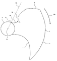
- FIG. 2 is a diagram showing a shape of the propeller fan according to the first embodiment projected on a plane perpendicular to the rotation axis.
- blade 5, ie, a pressure surface side is shown.
- the propeller fan 1 includes a boss 3 provided on the rotation axis CL, and a plurality of wings 5 provided on the outer peripheral side of the boss 3.
- the boss 3 rotates around the rotation axis CL.
- the plurality of wings 5 radially extend radially outward from the boss 3.
- the plurality of wings 5 are circumferentially spaced from one another in an equiangular range.
- the boss 3 corresponds to the “shaft portion” in the present invention.
- the arrow RD in the drawing indicates the rotational direction RD of the propeller fan 1.
- Arrow FD in the figure shows the flow direction FD of the air flow.
- blade 5 is three is illustrated, the number of sheets of the wing
- the wing 5 has a leading edge 7, a trailing edge 9, an outer peripheral edge 11 and an inner peripheral edge 13.
- the front edge 7 is formed on the advancing side in the rotational direction RD. That is, the front edge 7 is located forward with respect to the rotational direction RD.
- the rear edge 9 is formed on the reverse side in the rotational direction RD. That is, the rear edge 9 is located rearward with respect to the rotational direction RD.
- the inner peripheral edge 13 is a portion extending back and forth between the innermost circumference of the front edge 7 and the innermost circumference of the rear edge 9 in an arc shape.
- the wing 5 is connected to the outer periphery of the boss 3 at the inner peripheral edge 13.
- the outer peripheral edge 11 is a portion extending in an arc shape back and forth so as to connect the outermost periphery of the front edge 7 and the outermost periphery of the rear edge 9.
- the radius of a circle centered on the rotation axis CL and passing through the outer peripheral edge 11 is constant.
- arrow 8 indicates an air flow which flows to the pressure surface of the wing 5 when the propeller fan 1 rotates.
- the shape of the outer peripheral edge 11 is not limited to this.
- the shape of the outer peripheral edge 11 can apply an arbitrary shape.
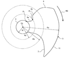
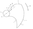
- FIG. 3 is a diagram for explaining the shape of a propeller fan blade according to the first embodiment.
- vertical to the rotating shaft CL is shown.
- only one wing 5 among the plurality of wings 5 is shown.
- the trailing edge 9 of the wing 5 has a first trailing edge 9a adjacent to the boss 3 and a second trailing edge 9b adjacent to the first trailing edge 9a.
- the first rear edge 9 a is a portion located on the innermost side of the rear edge 9.
- the second rear edge 9 b is a portion of the rear edge 9 adjacent to the outer peripheral side of the first rear edge 9 a.
- a connection point between the boss 3 and the first rear edge 9a is defined as a first connection point P1. That is, the innermost circumferential point of the first rear edge 9a is defined as a first connection point P1.
- a connection point between the first rear edge 9a and the second rear edge 9b is defined as a second connection point P2. Further, a straight line passing through the rotation axis CL and the first connection point P1 is defined as a reference line BL.
- the trailing edge 9 of the wing 5 is configured such that the second connection point P2 is positioned on the forward side in the rotational direction RD relative to the reference line BL.
- the trailing edge 9 of the wing 5 is configured such that the second trailing edge 9b is retracted to the reverse side in the rotational direction RD relative to the second connection point P2.
- the trailing edge 9 of the wing 5 is configured such that the first trailing edge 9a is positioned on the forward side in the rotational direction RD relative to the reference line BL. That is, the first rear edge 9a is a portion that advances from the first connection point P1 to the second connection point P2 on the advancing side in the rotational direction RD.
- the second rear edge 9 b is a portion that retracts toward the reverse side in the rotational direction RD with the second connection point P 2 as a starting point.
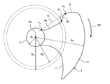
- FIG. 4 is a diagram for explaining the shape of a propeller fan blade according to the first embodiment.
- vertical to the rotating shaft CL is shown.
- only one wing 5 among the plurality of wings 5 is shown.
- a radius of a circle centered on the rotation axis CL and passing through the second connection point P2 is defined as a radius Rp.
- a radius of a circle passing through the outer peripheral edge 11 of the wing 5 with the rotation axis CL as a center is defined as a radius Ro.
- a radius of a circle that passes through the first connection point P1 with the rotation axis CL as a center is defined as a radius Ri.
- a radius between the radius Ro and the radius Ri is defined as a radius Rh. That is, the radius Rh, the radius Ro, and the radius Ri have the following relationship.
- the trailing edge 9 of the wing 5 has a radius Rp of a circle centered on the rotation axis CL and passing through the second connection point P2 smaller than a radius Rh between the radius Ro and the radius Ri. Is configured as.
- FIG. 5 is a diagram for explaining the shape of a propeller fan blade according to the first embodiment.
- vertical to the rotating shaft CL is shown.
- only one wing 5 among the plurality of wings 5 is shown.
- a contact point on the innermost circumferential side where the tangent line TL passes through the first connection point P1 is defined as a first vertex P3.
- the length of the first rear edge 9a is defined as a length L1.
- the length of the second trailing edge 9b between the second connection point P2 and the first vertex P3 is defined as a length L2.
- the trailing edge 9 of the wing 5 is configured such that the length L1 of the first trailing edge 9a is equal to or greater than the length L2 of the second trailing edge 9b.
- the trailing edge 9 of the wing 5 is configured such that the length L1 of the first trailing edge 9a is equal to or less than twice the length L2 of the second trailing edge 9b.
- the length L1 of the first rear edge 9a and the length L2 of the second rear edge 9b may be substantially the same.
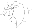
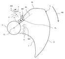
- FIG. 6 is a view schematically showing a propeller fan and a motor according to Embodiment 1, and an air flow.
- blade 5 is abbreviate
- the boss 3 of the propeller fan 1 is attached to a fan motor 61 which is a drive source.
- the boss 3 of the propeller fan 1 is rotated by the rotational force of the fan motor 61. Due to the rotation of the fan motor 61, the air flow 8 flows in from the front edge 7 of the wing 5, passes between the wings 5 and is released from the rear edge 9.
- the air flow passing between the blades 5 changes the air flow direction by the inclination and warp of the blades 5 as it flows along the blades 5, and the static pressure is increased by the change in momentum.
- the air stream immediately before flowing into the front edge portion 7 of the wing 5 includes a turbulent flow 21 in which the wind speed is nonuniform.
- the turbulent flow 21 is generated by a vortex generated when the fluid passes through the fan motor 61 or the boss 3.
- the turbulent flow 21 is generated by the increase of the local wind speed when the fluid passes through the flow path narrowed by the presence of the fan motor 61, the presence of the boss 3, or the presence of the vortex.
- FIG. 7 is a view showing the flow around the wing by developing the wing 5 at a position along the line AA.
- blade 5 is abbreviate
- FIG. 7 when the turbulent air flow 21 is included in the air flow just before flowing into the front edge portion 7 of the wing 5, a vortex X is generated at the front edge portion 7. More specifically, the direction 31 of the front edge 7 of the wing 5 on the inner peripheral side, that is, the tangential direction of the front edge 7 in the wing cross section does not coincide with the inflowing air flow direction 33. A vortex X is generated. The vortex X generated at the leading edge 7 flows along the wing surface of the wing 5 and is released from the trailing edge 9.
- FIG. 8 is a view schematically showing an air flow passing through the wing surface of the propeller fan according to the first embodiment.
- vertical to the rotating shaft CL is shown.
- only one wing 5 among the plurality of wings 5 is shown.
- the vortex X generated at the leading edge 7 flows on the wing surface of the wing 5 along the axis 36 X and is discharged from the trailing edge 9.
- a vortex Y having an axis 36 Y shaped along the edge of the trailing edge 9 is formed. That is, on the inner peripheral side of the wing 5, in the air flow released from the rear edge 9, the shaft 36Y having a convex shape in the rotational direction RD along the first rear edge 9a and the second rear edge 9b. Vortex Y is formed.
- the axis 36 X of the vortex X flowing on the wing surface of the wing 5 and the axis 36 Y of the vortex Y intersect at the trailing edge 9. For this reason, the vortex Y discharged from the first trailing edge 9a and the second trailing edge 9b and the vortex X collide with each other, and the air flow forming the vortex Y and the friction between the air flows forming the vortex X Vortex Y and vortex X are weakened.
- the trailing edge 9 of the wing 5 includes the first trailing edge 9a adjacent to the boss 3 and the second trailing edge 9b adjacent to the first trailing edge 9a.
- the second connection point P2 is positioned on the forward side in the rotational direction RD relative to the reference line BL, and the second rear edge 9b is configured to retract to the reverse side in the rotational direction RD relative to the second connection point P2. ing. Therefore, the vortex Y generated at the trailing edge 9 of the wing 5 is released with the twisted shaft 36Y, and the vortex Y is weakened by friction.
- a vortex X having an axis 36X generated at the front edge 7 of the wing 5 and a vortex Y generated at the rear edge 9 of the wing 5 are mixed downstream, and due to the friction between the two, the vortex X and the vortex Y mutually Be weakened. Therefore, the disturbance of the air flow is reduced and the energy loss is reduced. In addition, the turbulence of the air flow caused by the vortex X and the vortex Y can be reduced, and a propeller fan with reduced noise can be realized.
- propeller fan 1 in the first embodiment will be described in comparison with a comparative example.
- the same reference numerals as those of the propeller fan 1 of the first embodiment denote corresponding parts.
- FIG. 9 is a view for explaining the shape of a propeller fan blade in Comparative Example 1;
- vertical to the rotating shaft CL is shown.
- FIG. 9 only one wing 5 among the plurality of wings 5 is shown.
- the propeller fan 1 of Comparative Example 1 is configured such that the second connection point P2 is located on the reverse side in the rotational direction RD relative to the reference line BL. That is, the trailing edge 9 on the inner peripheral side of the wing 5 is formed along the blowing direction of the air flow.
- the direction of the axis 36X of the vortex X flowing on the blade surface and the axis 36Y of the vortex Y generated at the trailing edge 9 are the same. Therefore, the vortex Y and the vortex X do not cancel each other, and remain downstream, causing energy loss. Further, the turbulence of the air flow of the vortex X and the vortex Y generates noise.
- propeller fan 1 in the first embodiment can achieve the above-described effect since axis 36X of vortex X and axis 36Y of vortex Y intersect at the rear edge portion 9.
- FIG. 10 is a view for explaining the shape of a propeller fan blade in Comparative Example 2.
- vertical to the rotating shaft CL is shown.
- FIG. 10 only one wing 5 of the plurality of wings 5 is shown.
- the second connection point P2 is positioned on the reverse side of the rotational direction RD with respect to the reference line BL, and the first rear edge 9a and the second rear edge 9b is a structure located in the reverse side of the rotation direction RD rather than the reference line BL.
- the propeller fan in Comparative Example 2 has a convex shaft 36Y in the direction opposite to the rotational direction RD along the first rear edge 9a and the second rear edge 9b on the inner peripheral side of the wing 5.
- Vortex Y is formed. Therefore, the vortex Y discharged from the first rear edge 9a and the vortex Y discharged from the second rear edge 9b are separated from each other, and the air flows forming the vortex Y do not collide with each other, and the vortex Y weakens. There is nothing to be done.
- propeller fan 1 in the first embodiment exerts the above-described effect since vortex Y discharged from first rear edge 9a and vortex Y discharged from second rear edge 9b collide with each other. be able to.
- FIG. 11 is a view for explaining the shape of a propeller fan blade in Comparative Example 3.
- FIG. 12 is a view schematically showing an air flow passing through the wing surface of the propeller fan in Comparative Example 3. As shown in FIG. 11 and 12 show the shape of the propeller fan 1 projected on a plane perpendicular to the rotation axis CL. Further, in FIG. 11 and FIG. 12, only one wing 5 among the plurality of wings 5 is shown.
- propeller fan 1 of Comparative Example 3 has a configuration in which radius Rp of a circle centered on rotation axis CL and passing through second connection point P2 is larger than radius Rh between the radius Ro and radius Ri. It is.
- the length L1 of the first rear edge 9a is more than twice the length L2 of the second rear edge 9b.
- the shape of the shaft 36Y along the first rear edge 9a and the second rear edge 9b approaches a linear shape in the radial direction.
- the amount of vortices Y released from the first trailing edge 9a is larger than the amount of vortices Y released from the second trailing edge 9b.
- propeller fan 1 in the first embodiment exerts the above-described effect since vortex Y discharged from first rear edge 9a and vortex Y discharged from second rear edge 9b collide with each other. be able to.
- propeller fan 1 in the second embodiment will be described focusing on differences from the first embodiment.
- the same components as in the first embodiment will be assigned the same reference numerals and descriptions thereof will be omitted.
- FIG. 13 is a diagram for explaining the shape of a propeller fan blade in the second embodiment.
- vertical to the rotating shaft CL is shown.
- only one wing 5 among the plurality of wings 5 is shown.
- the trailing edge 9 of the wing 5 is configured such that the second connection point P2 is located on the reference line BL.
- the trailing edge 9 of the wing 5 is configured such that the first trailing edge 9a is located on the reference line BL. That is, the first rear edge 9a is a portion extending from the first connection point P1 to the second connection point P2 on the reference line BL.
- the second rear edge 9 b is a portion that retracts toward the reverse side in the rotational direction RD with the second connection point P 2 as a starting point.
- FIG. 14 is a view schematically showing an air flow passing through the blade surface of the propeller fan according to the second embodiment.
- vertical to the rotating shaft CL is shown.
- only one wing 5 among the plurality of wings 5 is shown.
- the air flow released from the rear edge 9 is directed along the first rear edge 9 a and the second rear edge 9 b in the rotational direction RD.
- a vortex Y having a convex axis 36Y is formed.
- the vortex Y is weakened by the friction of. Further, the vortex Y discharged from the first trailing edge 9a and the second trailing edge 9b is twisted as it goes downstream, the amount of bending of the shaft 36Y increases, and the air flows forming the vortex Y as they go downstream It becomes easy to collide and the vortex Y is weakened.
- the axis 36 X of the vortex X flowing on the wing surface of the wing 5 and the axis 36 Y of the vortex Y intersect at the trailing edge 9. For this reason, the vortex Y discharged from the first trailing edge 9a and the second trailing edge 9b and the vortex X collide with each other, and the air flow forming the vortex Y and the friction between the air flows forming the vortex X Vortex Y and vortex X are weakened.
- propeller fan 1 according to the third embodiment will be described focusing on differences from the first and second embodiments.
- the same reference numerals as in the first and second embodiments denote the same parts as in the first and second embodiments, and a description thereof will be omitted.
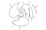
- FIG. 15 is a diagram showing a shape of the propeller fan according to Embodiment 3 projected on a plane perpendicular to the rotation axis.
- blade 5, ie, a pressure surface side, is shown.
- connection point between the front edge 7 and the boss 3 is defined as a third connection point P4.
- the distance between the rotation axis CL and the third connection point P4 is defined as a distance Df.
- the distance between the rotation axis CL and the first connection point P1 is defined as a distance Db.
- the boss 3 is configured such that the distance Db between the rotation axis CL and the first connection point P1 is longer than the distance Df between the rotation axis CL and the third connection point P4.
- the wing 5 is configured such that the distance Dwf between the third connection point P4 and the outer peripheral edge 11 is longer than the distance Dwb between the first connection point P1 and the outer peripheral edge 11. That is, the rear edge 9 of the side wall of the boss 3 is formed radially outward of the front edge 7.
- FIG. 16 is a diagram schematically showing an air flow passing through the wing surface of the propeller fan in the third embodiment.
- vertical to the rotating shaft CL is shown.
- only one wing 5 among the plurality of wings 5 is shown.
- the distance on the wing surface through which the vortex X generated at the wing leading edge 7 passes is shortened from the distance Dwf to the distance Dwb from the leading edge 7 to the trailing edge 9. That is, the region through which the air flow passes is narrowed by the side wall of the boss 3 and the outer peripheral edge 11.
- the vortex X passing on the wing surface is contracted and accelerated toward the trailing edge side. Then, the velocity at the time of collision with the vortex Y generated at the trailing edge 9 is increased, and the effect of weakening the vortex Y generated at the trailing edge 9 becomes stronger. Therefore, compared with the first embodiment, the disturbance of the air flow is further reduced, and the energy loss is reduced. Further, compared with the first embodiment, the propeller fan can be realized in which the disturbance of the air flow accompanying the vortex X and the vortex Y is further reduced and the noise is also reduced.
- propeller fan 1 according to the fourth embodiment will be described focusing on differences from the first to third embodiments.
- the same reference numerals as in the first to third embodiments denote the same parts as in the first to third embodiments, and a description thereof will be omitted.
- FIG. 17 is a diagram showing a shape of the propeller fan according to the fourth embodiment projected on a plane perpendicular to the rotation axis.
- blade 5, ie, the pressure surface side is shown.
- FIG. 18 is a diagram showing a shape in which the propeller fan according to the fourth embodiment is rotationally projected onto a plane including the rotation axis. That is, FIG. 18 is a view showing the region where the wing 5 is viewed from the side when the propeller fan 1 is rotated.
- the middle point of the arc connecting the front edge 7 and the rear edge 9 at the inner peripheral edge 13 of the wing 5 at the same radius centering on the rotation axis CL is a first midpoint Define as P5. That is, the middle point of the arc connecting the innermost circumference of the front edge 7 of the wing 5 and the innermost circumference of the rear edge 9 at the same radius centering on the rotation axis CL is a first midpoint P5. Define as Further, a middle point of an arc connecting the front edge portion 7 and the rear edge portion 9 in the outer peripheral edge 11 of the wing 5 at the same radius centering on the rotation axis CL is defined as a second middle point P6.
- the wing 5 is configured such that the first midpoint P5 is located upstream of the second midpoint P6 in the direction along the rotation axis CL (see FIG. 18). That is, the wing 5 is a so-called aft wing.
- the configuration of the rear edge portion 9 is the same as any one of the first to third embodiments.
- the wing 5 is a rearward-tilt wing, the direction in which the wing 5 pushes out the air flow is directed radially inward. Therefore, the flow of the air flow 8 leaking from the outer peripheral edge 11 can be suppressed, and the disturbance of the air flow 8 can be reduced.
- the air flow 8 is directed to the inner peripheral side, even when the vortex X generated on the inner peripheral side of the wing 5 and the air flow 8 are mixed, they are generated at the rear edge 9 on the inner peripheral side of the wing 5 It can be weakened mutually with the vortex Y. Therefore, even when the wing 5 is a backward-tilted wing, turbulence of the air flow is reduced, energy loss is reduced, and a propeller fan that reduces noise can be realized.
- Embodiment 5 propeller fan 1 in the fifth embodiment will be described focusing on differences from the above first to fourth embodiments.
- the same components as those in the first to fourth embodiments are assigned the same reference numerals and descriptions thereof will be omitted.
- FIG. 19 is a diagram showing the shape of the propeller fan according to the fifth embodiment projected on a plane perpendicular to the rotation axis.
- blade 5, ie, a pressure surface side is shown.
- the propeller fan 1 is adjacent to the shaft portion 4 provided on the rotation shaft CL, the plurality of blades 5 provided on the outer peripheral side of the shaft portion 4, and the plurality of blades 5 in the circumferential direction. It has a plurality of connecting parts 10 which connect two wings 5 which fit each other.
- Each of the plurality of connection portions 10 has, for example, a plate-like shape, and is provided adjacent to the outer peripheral side of the shaft portion 4.
- Each of the plurality of connection portions 10 is a rear edge 9 of the wing 5 located forward in the rotational direction RD of the propeller fan 1 among the two wings 5 adjacent in the circumferential direction, and a rear side in the rotational direction RD It connects with the front edge 7 of the wing 5 located.
- the propeller fan 1 is a so-called bossless propeller fan that does not have the boss 3.
- the shaft portion 4, the plurality of wings 5 and the plurality of connection portions 10 are integrally formed of resin. That is, the shaft portion 4, the plurality of wings 5 and the plurality of connection portions 10 constitute an integral wing.
- the configuration of the trailing edge 9 of the wing 5 is the same as that of any of the first to fourth embodiments. That is, the first rear edge 9 a is located on the innermost side of the rear edge 9. The second rear edge 9 b is a portion of the rear edge 9 adjacent to the outer peripheral side of the first rear edge 9 a.
- a point on the innermost circumferential side of the first rear edge 9a is a first connection point P1. That is, among the two wings 5 adjacent in the circumferential direction, the rear edge 9 of the wing 5 located forward in the rotational direction RD and the front edge 7 of the wing 5 located rearward in the rotational direction RD The connection point is the first connection point P1.
- the plurality of wings 5 provided on the outer peripheral side of the shaft portion 4 and the plurality of wings 5 provided adjacent to the shaft portion 4 are adjacent to each other in the circumferential direction. And a connecting portion 10 for connecting the two wings 5 together. According to this configuration, the same effect as that of the first embodiment can be obtained.
- the present invention relates to high efficiency and low noise reduction of a propeller fan, but if the fan is mounted on a blower, the amount of blast can be increased with high efficiency. Moreover, if it mounts in the air conditioner which is a refrigeration cycle apparatus comprised with a compressor, a heat exchanger, etc. or the hot water supply outdoor unit, the heat exchanger passage air volume can be earned with low noise and high efficiency, Noise reduction and energy saving can be realized.
- the propeller fan 1 of the first to fifth embodiments is applied to an outdoor unit of an air conditioner as an outdoor unit including a blower.
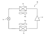
- FIG. 20 is a schematic view of an air conditioner which is a refrigeration cycle apparatus according to the sixth embodiment.
- the air conditioner includes a refrigerant circuit 70 in which a compressor 64, a condenser 72, an expansion valve 74, and an evaporator 73 are connected in order by a refrigerant pipe.
- a condenser fan 72a that blows air for heat exchange to the condenser 72 is disposed.
- an evaporator fan 73a for blowing air for heat exchange to the evaporator 73 is disposed.
- At least one of the condenser fan 72a and the evaporator fan 73a is configured by the propeller fan 1 according to any one of the first to fifth embodiments.
- the refrigerant circuit 70 may be provided with a four-way valve or the like that switches the flow of the refrigerant to switch the heating operation and the cooling operation.
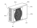
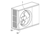
- FIG. 21 is a perspective view of the outdoor unit as the air blower according to the sixth embodiment, as viewed from the air outlet side.
- FIG. 22 is a diagram for describing the configuration of the outdoor unit from the upper surface side.
- FIG. 23 is a view showing the outdoor unit with the fan grill removed.
- FIG. 24 is a view showing an internal configuration by removing a fan grill, a front panel, and the like from the outdoor unit.
- the outdoor unit main body 51 which is a casing, is configured as a housing having a pair of left and right side surfaces 51a and 51c, a front surface 51b, a rear surface 51d, an upper surface 51e, and a bottom surface 51f.
- the side surface 51a and the back surface 51d have an opening portion for drawing in air from the outside. Further, in the front surface 51b, the front panel 52 is formed with an outlet 53 as an opening for blowing air to the outside. Furthermore, the air outlet 53 is covered with a fan grill 54, thereby preventing contact of an object or the like with the propeller fan 1 for safety. Arrow A in FIG. 22 indicates the flow of air.
- a propeller fan 1 is installed in the outdoor unit body 51.
- the propeller fan 1 is connected to a fan motor 61, which is a drive source on the rear surface 51d side, via a rotation shaft 62, and is rotationally driven by the fan motor 61.
- the inside of the outdoor unit body 51 is divided by a partition plate 51g, which is a wall, into an air blowing chamber 56 in which the propeller fan 1 is installed, and a machine chamber 57 in which a compressor 64 and the like are installed.
- a heat exchanger 68 which extends in a substantially L shape in plan view is provided on the side surface 51 a side and the back surface 51 d side in the air blowing chamber 56. The heat exchanger 68 functions as the condenser 72 during heating operation and functions as the evaporator 73 during cooling operation.
- a bell mouth 63 is disposed radially outward of the propeller fan 1 disposed in the blowing chamber 56.
- the bell mouth 63 is located outside the outer peripheral end of the wing 5 and has an annular shape along the rotational direction of the propeller fan 1. Further, the partition plate 51g is positioned on one side of the bell mouth 63, and a part of the heat exchanger 68 is positioned on the other side.
- the front end of the bell mouth 63 is connected to the front panel 52 of the outdoor unit so as to surround the outer periphery of the air outlet 53.
- the bell mouth 63 may be configured integrally with the front panel 52, or may be prepared separately as a separate body.
- the flow path between the suction side and the blow-out side of the bell mouth 63 is configured as an air path near the blowout port 53 by the bell mouth 63. That is, the air passage in the vicinity of the air outlet 53 is separated by the bell mouth 63 from the other space in the air blowing chamber 56.
- the heat exchanger 68 provided on the suction side of the propeller fan 1 includes a plurality of fins arranged in parallel so that the plate-like faces are in parallel, and a heat transfer tube passing through each fin in the direction in which the fins are arranged. Have. A refrigerant circulating in the refrigerant circuit flows through the heat transfer pipe.
- the heat exchanger 68 of the present embodiment is configured such that the heat transfer tubes extend in an L-shape across the side surface 51 a and the back surface 51 d of the outdoor unit main body 51 and the heat transfer tubes of multiple stages meander while penetrating the fins. .
- the heat exchanger 68 is connected to the compressor 64 through the piping 65 and the like, and further connected to the indoor heat exchanger and the expansion valve, etc. (not shown) to constitute the refrigerant circuit 70 of the air conditioner. .
- a substrate box 66 is disposed in the machine room 57, and a control substrate 67 provided in the substrate box 66 controls equipment mounted in the outdoor unit.
- this Embodiment 6 demonstrated the outdoor unit of the air conditioning apparatus as an example as an outdoor unit containing a ventilation apparatus, this invention is not limited to this.
- the air blower can be implemented as an outdoor unit such as a water heater, and can be widely applied as an apparatus for blowing air, and can also be applied to an apparatus or facility other than an outdoor unit. is there.
- 1 propeller fan 3 boss, 5 wings, 7 front edge, 9 rear edge, 9a first rear edge, 9b second rear edge, 11 outer peripheral edge, 13 inner peripheral edge, 31 direction, 33 air flow direction, 51 Outdoor unit body, 51a side, 51b front, 51c side, 51d back, 51e top, 51f bottom, 51g partition plate, 52 front panel, 53 outlet, 54 fan grille, 56 air chamber, 57 machine room, 61 fan motor, 62 rotary shaft, 63 bellmouth, 64 compressor, 65 piping, 66 board box, 67 control board, 68 heat exchanger, 70 refrigerant circuit, 72 condenser, 72a fan for condenser, 73 evaporator, 73a fan for evaporator, 74 expansion valve.
Landscapes
- Engineering & Computer Science (AREA)
- Mechanical Engineering (AREA)
- General Engineering & Computer Science (AREA)
- Chemical & Material Sciences (AREA)
- Combustion & Propulsion (AREA)
- Physics & Mathematics (AREA)
- Thermal Sciences (AREA)
- Structures Of Non-Positive Displacement Pumps (AREA)
Abstract
Description
(全体構成)
図1は、実施の形態1におけるプロペラファンの概略構成を示す斜視図である。
図2は、実施の形態1におけるプロペラファンを回転軸に垂直な面に投影した形状を示す図である。なお、図2においては、翼5の表面の気流を押す側の面、すなわち圧力面側から見た形状を示す。
図1及び図2に示すように、プロペラファン1は、回転軸CL上に設けられたボス3と、ボス3の外周側に設けられた複数の翼5とを備える。ボス3は、回転軸CLを中心に回転する。複数の翼5は、ボス3から径方向外側に放射状に延びて構成されている。複数の翼5は、相互に等角度範囲で周方向に離隔している。
なお、ボス3は、本発明における「軸部」に相当する。
次に、後縁部9の構成の詳細について説明する。
Rh=(Ro-Ri)/2
次に、実施の形態1におけるプロペラファン1の動作について説明する。
図6に示すように、プロペラファン1のボス3は、駆動源であるファンモータ61に取り付けられる。プロペラファン1のボス3は、ファンモータ61の回転力によって回転する。ファンモータ61の回転により、気流8が翼5の前縁部7から流入し、翼5の間を通過して、後縁部9から放出される。翼5の間を通過する気流は、翼5に沿って流れるときに翼5の傾き及び反りによって気流方向を変えられ、運動量変化により静圧上昇する。
翼5における内周側の上流には、円筒状のボス3及びファンモータ61が存在する。このため、翼5の前縁部7に流入する直前の気流には、風速が不均一である、乱れた流れ21が含まれる。例えば、乱れた流れ21は、流体がファンモータ61又はボス3を通過するときに発生した渦によって発生する。また例えば、乱れた流れ21は、ファンモータ61の存在、ボス3の存在、または渦の存在によって狭くなった流路を流体が通過するときに、局所的な風速の増加によって発生する。
図7に示すように、翼5の前縁部7に流入する直前の気流に、乱れた流れ21が含まれると、前縁部7で渦Xが発生する。より詳細には、内周側の翼5の前縁部7の向き31、すなわち翼断面でいう前縁部7の接線方向と、流入する気流方向33とが一致せず、前縁部7で渦Xが発生する。前縁部7で発生した渦Xは、翼5の翼面に沿って流れ、後縁部9から放出される。
図8に示すように、前縁部7で発生した渦Xは、翼5の翼面上を軸36Xに沿って流れ、後縁部9から放出される。また、翼5の後縁部9から放出された気流には、後縁部9の縁に沿った形状の軸36Yをもつ渦Yが形成される。すなわち、翼5の内周側において、後縁部9から放出された気流には、第1後縁部9aと第2後縁部9bに沿って、回転方向RDに向かって凸状の軸36Yをもつ渦Yが形成される。
以上のように本実施の形態1においては、翼5の後縁部9は、ボス3に隣接する第1後縁部9aと、第1後縁部9aに隣接する第2後縁部9bとを有する。第2接続点P2が、基準線BLよりも回転方向RDの前進側に位置し、第2後縁部9bが、第2接続点P2よりも回転方向RDの後進側に後退するように構成されている。
このため、翼5の後縁部9で発生する渦Yが捻れた軸36Yをもって放出され、渦Yが摩擦により弱められる。また、翼5の前縁部7で発生した軸36Xをもつ渦Xと、翼5の後縁部9で発生する渦Yが下流で混合し、両者の摩擦により渦X及び渦Yが相互に弱められる。よって、気流の乱れが小さくなり、エネルギー損失が低減される。また、渦X及び渦Yに伴う気流の乱れが小さくなり、騒音も低減するプロペラファンを実現できる。
図9は、比較例1におけるプロペラファンの翼の形状を説明する図である。なお、図9においては、プロペラファン1を回転軸CLに垂直な面に投影した形状を示す。また、図9においては、複数の翼5のうち1枚の翼5のみを示す。
図9に示すように、比較例1のプロペラファン1は、第2接続点P2が、基準線BLよりも回転方向RDの後進側に位置する構成である。すなわち、翼5の内周側の後縁部9が気流の吹出し方向に沿って形成されている。
図10は、比較例2におけるプロペラファンの翼の形状を説明する図である。なお、図10においては、プロペラファン1を回転軸CLに垂直な面に投影した形状を示す。また、図10においては、複数の翼5のうち1枚の翼5のみを示す。
図10に示すように、比較例2のプロペラファン1は、第2接続点P2が、基準線BLよりも回転方向RDの後進側に位置し、第1後縁部9a及び第2後縁部9bが、基準線BLよりも回転方向RDの後進側に位置する構成である。
図11は、比較例3におけるプロペラファンの翼の形状を説明する図である。
図12は、比較例3におけるプロペラファンの翼面を通過する気流の様子を模式的に示す図である。
なお、図11及び図12においては、プロペラファン1を回転軸CLに垂直な面に投影した形状を示す。また、図11及び図12においては、複数の翼5のうち1枚の翼5のみを示す。
以下、実施の形態2におけるプロペラファン1について、上記実施の形態1との相違点を中心に説明する。実施の形態1と共通の構成は、同一符号を付し説明を省略する。
図14に示すように、翼5の内周側において、後縁部9から放出された気流には、第1後縁部9aと第2後縁部9bに沿って、回転方向RDに向かって凸状の軸36Yをもつ渦Yが形成される。
以下、実施の形態3におけるプロペラファン1について、上記実施の形態1及び2との相違点を中心に説明する。実施の形態1及び2と共通の構成は、同一符号を付し説明を省略する。
よって、上記実施の形態1と比較して、さらに、気流の乱れが小さくなり、エネルギー損失が低減される。また、上記実施の形態1と比較して、さらに、渦X及び渦Yに伴う気流の乱れが小さくなり、騒音も低減するプロペラファンを実現できる。
以下、実施の形態4におけるプロペラファン1について、上記実施の形態1~3との相違点を中心に説明する。実施の形態1~3と共通の構成は、同一符号を付し説明を省略する。
図18は、実施の形態4におけるプロペラファンを、回転軸を含む面に回転投影した形状を示す図である。つまり、図18は、プロペラファン1を回転させた際に、側面から見た翼5の存在領域を示した図である。
以下、実施の形態5におけるプロペラファン1について、上記実施の形態1~4との相違点を中心に説明する。実施の形態1~4と共通の構成は、同一符号を付し説明を省略する。
図19に示すように、プロペラファン1は、回転軸CLに設けられた軸部4と、軸部4の外周側に設けられた複数の翼5と、複数の翼5のうち周方向で隣り合う2つの翼5同士を接続する複数の接続部10と、を有している。
上述したように本発明はプロペラファンの高効率及び低騒音化に関するものであるが、このファンを送風装置に搭載すれば、高効率で送風量を増加することができる。また、圧縮機と熱交換器などで構成される冷凍サイクル装置である空気調和機又は給湯用室外機に搭載すれば、低騒音かつ高効率で熱交換器通過風量を稼ぐことができ、機器の低騒音化と省エネルギー化を実現することができる。本実施の形態6は、そのような一例として、上記実施の形態1~5のプロペラファン1を、送風装置を含む室外機としての空気調和装置の室外機に適用した場合について説明する。
図20に示すように、空気調和装置は、圧縮機64と凝縮器72と膨張弁74と蒸発器73とを順番に冷媒配管で接続した冷媒回路70を備えている。凝縮器72には、熱交換用の空気を凝縮器72に送風する凝縮器用ファン72aが配置されている。また、蒸発器73には、熱交換用の空気を蒸発器73に送風する蒸発器用ファン73aが配置されている。凝縮器用ファン72a及び蒸発器用ファン73aの少なくとも一方は、上記実施の形態1~5の何れかのプロペラファン1によって構成される。なお、冷媒回路70に、冷媒の流れを切り替える四方弁等を設け、暖房運転と冷房運転とを切り替える構成としても良い。
図22は、上面側から室外機の構成を説明するための図である。
図23は、室外機からファングリルを外した状態を示す図である。
図24は、室外機からファングリル及び前面パネル等を除去して、内部構成を示す図である。
図21~図24に示すように、ケーシングである室外機本体51は、左右一対の側面51a及び側面51c、前面51b、背面51d、上面51e並びに底面51fを有する筐体として構成されている。側面51a及び背面51dは、外部から空気を吸込むために開口部分を有している。また、前面51bにおいては、前面パネル52に、外部に空気を吹出すための開口部分としての吹出口53が形成されている。さらに、吹出口53は、ファングリル54で覆われており、それにより、物体等とプロペラファン1との接触を防止し、安全が図られている。なお、図22の矢印Aは、空気の流れを示している。
Claims (10)
- 回転軸上に設けられた軸部と、
前記軸部の外周側に設けられた翼と、を備え、
前記翼は、回転方向の後進側に形成された後縁部を有し、
前記後縁部は、
最も内周側に位置する第1後縁部と、
前記第1後縁部の外周側に隣接する第2後縁部と、を含み、
前記第1後縁部の最も内周側の点を第1接続点と定義し、
前記第1後縁部と前記第2後縁部との接続点を第2接続点と定義し、
前記回転軸と前記第1接続点とを通る直線を基準線と定義したとき、
前記第2接続点が、前記基準線よりも前記回転方向の前進側、又は前記基準線上に位置し、
前記第2後縁部が、前記第2接続点よりも前記回転方向の後進側に後退するように構成された
プロペラファン。 - 前記第1後縁部が、前記基準線よりも前記回転方向の前進側、又は前記基準線上に位置するように構成された
請求項1に記載のプロペラファン。 - 前記回転軸を中心とし前記第2接続点を通る円の半径が、
前記回転軸を中心とし前記翼の外周縁を通る円の半径と、前記回転軸を中心とし前記第1接続点を通る円の半径との中間の半径よりも小さい
請求項1又は2に記載のプロペラファン。 - 前記第2後縁部のうち、接線が前記第1接続点を通る最も内周側の接点を第1頂点と定義したとき、
前記第1後縁部の長さが、前記第2接続点と前記第1頂点との間の前記第2後縁部の長さ以上である
請求項1~3の何れか一項に記載のプロペラファン。 - 前記第1後縁部の長さが、前記第2接続点と前記第1頂点との間の前記第2後縁部の長さの2倍以下である
請求項4に記載のプロペラファン。 - 前記翼は、前記回転方向の前進側に形成された前縁部を有し、
前記前縁部の最も内周側と前記後縁部の最も内周側とを、前記回転軸を中心とした同一の半径で結ぶ円弧の中点を、第1中間点と定義し、
当該翼の外周を形成する外周縁の前記前縁部及び前記後縁部を、前記回転軸を中心とした同一の半径で結ぶ円弧の中点を、第2中間点と定義したとき、
前記第1中間点が、前記回転軸に沿った方向において前記第2中間点よりも上流側に位置するように構成された
請求項1~5の何れか一項に記載のプロペラファン。 - 前記翼は、前記軸部の外周に接続され、
前記回転方向の前進側に形成された前縁部と前記軸部との接続点を第3接続点と定義したとき、
前記軸部は、
前記回転軸と前記第1接続点との距離が、
前記回転軸と前記第3接続点との距離よりも長くなるように構成された
請求項1~6の何れか一項に記載のプロペラファン。 - 前記翼は、前記軸部の外周側に設けられた複数の翼の1つであり、
前記軸部に隣接して設けられ、前記複数の翼のうち前記回転軸を中心とする周方向で隣り合う2つの翼同士を接続する接続部を備えた
請求項1~6の何れか一項に記載のプロペラファン。 - 請求項1~8の何れか一項に記載のプロペラファンと、
前記プロペラファンに駆動力を付与する駆動源と、
前記プロペラファン及び前記駆動源を収容するケーシングと、を備えた
送風装置。 - 請求項9に記載の送風装置と、
凝縮器及び蒸発器を有する冷媒回路と、を備え、
前記送風装置は、
前記凝縮器及び前記蒸発器の少なくとも一方に空気を送風する
冷凍サイクル装置。
Priority Applications (7)
| Application Number | Priority Date | Filing Date | Title |
|---|---|---|---|
| EP17920624.8A EP3667096B1 (en) | 2017-08-09 | 2017-08-09 | Propeller fan, air blowing device, and refrigerating cycle device |
| JP2019535513A JP6811866B2 (ja) | 2017-08-09 | 2017-08-09 | プロペラファン、送風装置、及び冷凍サイクル装置 |
| AU2017427464A AU2017427464B2 (en) | 2017-08-09 | 2017-08-09 | Propeller fan, air-sending device, and refrigeration cycle apparatus |
| US16/620,650 US11187239B2 (en) | 2017-08-09 | 2017-08-09 | Propeller fan, air-sending device, and refrigeration cycle apparatus |
| CN201780093633.3A CN111033055B (zh) | 2017-08-09 | 2017-08-09 | 螺旋桨式风扇、送风装置以及制冷循环装置 |
| PCT/JP2017/028957 WO2019030866A1 (ja) | 2017-08-09 | 2017-08-09 | プロペラファン、送風装置、及び冷凍サイクル装置 |
| ES17920624T ES2934466T3 (es) | 2017-08-09 | 2017-08-09 | Ventilador de hélice, dispositivo de soplado de aire y dispositivo de ciclo de refrigeración |
Applications Claiming Priority (1)
| Application Number | Priority Date | Filing Date | Title |
|---|---|---|---|
| PCT/JP2017/028957 WO2019030866A1 (ja) | 2017-08-09 | 2017-08-09 | プロペラファン、送風装置、及び冷凍サイクル装置 |
Publications (1)
| Publication Number | Publication Date |
|---|---|
| WO2019030866A1 true WO2019030866A1 (ja) | 2019-02-14 |
Family
ID=65272631
Family Applications (1)
| Application Number | Title | Priority Date | Filing Date |
|---|---|---|---|
| PCT/JP2017/028957 Ceased WO2019030866A1 (ja) | 2017-08-09 | 2017-08-09 | プロペラファン、送風装置、及び冷凍サイクル装置 |
Country Status (7)
| Country | Link |
|---|---|
| US (1) | US11187239B2 (ja) |
| EP (1) | EP3667096B1 (ja) |
| JP (1) | JP6811866B2 (ja) |
| CN (1) | CN111033055B (ja) |
| AU (1) | AU2017427464B2 (ja) |
| ES (1) | ES2934466T3 (ja) |
| WO (1) | WO2019030866A1 (ja) |
Cited By (4)
| Publication number | Priority date | Publication date | Assignee | Title |
|---|---|---|---|---|
| JP2021088932A (ja) * | 2019-12-02 | 2021-06-10 | 株式会社コロナ | プロペラファン |
| JPWO2022091225A1 (ja) * | 2020-10-27 | 2022-05-05 | ||
| CN114641619A (zh) * | 2019-11-12 | 2022-06-17 | 三菱电机株式会社 | 轴流风扇、送风装置及制冷循环装置 |
| JP2024099344A (ja) * | 2023-01-12 | 2024-07-25 | 株式会社東芝 | 鉄道車両用の空調装置の室外送風機 |
Families Citing this family (1)
| Publication number | Priority date | Publication date | Assignee | Title |
|---|---|---|---|---|
| USD1047125S1 (en) * | 2022-07-27 | 2024-10-15 | Regal Beloit Italy S.P.A. | Fan wheel |
Citations (10)
| Publication number | Priority date | Publication date | Assignee | Title |
|---|---|---|---|---|
| US4135858A (en) * | 1975-06-18 | 1979-01-23 | Marcel Entat | Method of producing propeller blades and improved propeller blades obtained by means of this method |
| JPS5525666U (ja) * | 1978-08-10 | 1980-02-19 | ||
| JPH0849697A (ja) * | 1994-08-05 | 1996-02-20 | Daikin Ind Ltd | ファン |
| JP2004346775A (ja) * | 2003-05-20 | 2004-12-09 | Hitachi Constr Mach Co Ltd | プロペラファン並びにエンジン冷却装置及び建設機械 |
| JP2010101223A (ja) * | 2008-10-22 | 2010-05-06 | Sharp Corp | プロペラファン、流体送り装置および成型金型 |
| WO2014103702A1 (ja) * | 2012-12-27 | 2014-07-03 | 三菱電機株式会社 | プロペラファン、送風装置、室外機 |
| WO2014162758A1 (ja) * | 2013-04-04 | 2014-10-09 | 三菱電機株式会社 | プロペラファン、送風装置及び室外機 |
| JP2015190332A (ja) | 2014-03-27 | 2015-11-02 | 三菱電機株式会社 | 軸流送風機、換気装置及び冷凍サイクル装置 |
| WO2016021555A1 (ja) * | 2014-08-07 | 2016-02-11 | 三菱電機株式会社 | 軸流ファン、及び、その軸流ファンを有する空気調和機 |
| WO2017154246A1 (ja) * | 2016-03-07 | 2017-09-14 | 三菱電機株式会社 | 軸流送風機および室外機 |
Family Cites Families (7)
| Publication number | Priority date | Publication date | Assignee | Title |
|---|---|---|---|---|
| AU6530680A (en) * | 1977-05-31 | 1981-04-16 | Allware Agencies Ltd. | Fan blade assemblies for box fans |
| DE102004059988A1 (de) * | 2004-12-13 | 2006-06-14 | Asia Vital Components Co., Ltd. | Kühlventilator mit zentraler Lufteinführung |
| JP5434235B2 (ja) | 2009-04-27 | 2014-03-05 | 三洋電機株式会社 | 室外機 |
| KR101639814B1 (ko) * | 2009-11-20 | 2016-07-22 | 엘지전자 주식회사 | 냉장 및 냉동 복합 공조시스템 |
| KR20130109515A (ko) * | 2012-03-27 | 2013-10-08 | 삼성전자주식회사 | 공조기기의의 실외기의 축류팬 |
| CN103511339B (zh) * | 2012-06-29 | 2016-02-03 | 珠海格力电器股份有限公司 | 空调、轴流风机及其轴流风叶 |
| JP2016166000A (ja) | 2016-04-06 | 2016-09-15 | 株式会社東芝 | 車両用電力変換装置 |
-
2017
- 2017-08-09 WO PCT/JP2017/028957 patent/WO2019030866A1/ja not_active Ceased
- 2017-08-09 ES ES17920624T patent/ES2934466T3/es active Active
- 2017-08-09 US US16/620,650 patent/US11187239B2/en active Active
- 2017-08-09 JP JP2019535513A patent/JP6811866B2/ja not_active Expired - Fee Related
- 2017-08-09 CN CN201780093633.3A patent/CN111033055B/zh not_active Expired - Fee Related
- 2017-08-09 EP EP17920624.8A patent/EP3667096B1/en active Active
- 2017-08-09 AU AU2017427464A patent/AU2017427464B2/en not_active Ceased
Patent Citations (10)
| Publication number | Priority date | Publication date | Assignee | Title |
|---|---|---|---|---|
| US4135858A (en) * | 1975-06-18 | 1979-01-23 | Marcel Entat | Method of producing propeller blades and improved propeller blades obtained by means of this method |
| JPS5525666U (ja) * | 1978-08-10 | 1980-02-19 | ||
| JPH0849697A (ja) * | 1994-08-05 | 1996-02-20 | Daikin Ind Ltd | ファン |
| JP2004346775A (ja) * | 2003-05-20 | 2004-12-09 | Hitachi Constr Mach Co Ltd | プロペラファン並びにエンジン冷却装置及び建設機械 |
| JP2010101223A (ja) * | 2008-10-22 | 2010-05-06 | Sharp Corp | プロペラファン、流体送り装置および成型金型 |
| WO2014103702A1 (ja) * | 2012-12-27 | 2014-07-03 | 三菱電機株式会社 | プロペラファン、送風装置、室外機 |
| WO2014162758A1 (ja) * | 2013-04-04 | 2014-10-09 | 三菱電機株式会社 | プロペラファン、送風装置及び室外機 |
| JP2015190332A (ja) | 2014-03-27 | 2015-11-02 | 三菱電機株式会社 | 軸流送風機、換気装置及び冷凍サイクル装置 |
| WO2016021555A1 (ja) * | 2014-08-07 | 2016-02-11 | 三菱電機株式会社 | 軸流ファン、及び、その軸流ファンを有する空気調和機 |
| WO2017154246A1 (ja) * | 2016-03-07 | 2017-09-14 | 三菱電機株式会社 | 軸流送風機および室外機 |
Non-Patent Citations (1)
| Title |
|---|
| See also references of EP3667096A4 |
Cited By (7)
| Publication number | Priority date | Publication date | Assignee | Title |
|---|---|---|---|---|
| CN114641619A (zh) * | 2019-11-12 | 2022-06-17 | 三菱电机株式会社 | 轴流风扇、送风装置及制冷循环装置 |
| JP2021088932A (ja) * | 2019-12-02 | 2021-06-10 | 株式会社コロナ | プロペラファン |
| JP7241667B2 (ja) | 2019-12-02 | 2023-03-17 | 株式会社コロナ | プロペラファン |
| JPWO2022091225A1 (ja) * | 2020-10-27 | 2022-05-05 | ||
| WO2022091225A1 (ja) * | 2020-10-27 | 2022-05-05 | 三菱電機株式会社 | 軸流ファン、送風装置および冷凍サイクル装置 |
| EP4239201A4 (en) * | 2020-10-27 | 2023-12-13 | Mitsubishi Electric Corporation | AXIAL FAN, BLOWING DEVICE AND REFRIGERANT CIRCUIT DEVICE |
| JP2024099344A (ja) * | 2023-01-12 | 2024-07-25 | 株式会社東芝 | 鉄道車両用の空調装置の室外送風機 |
Also Published As
| Publication number | Publication date |
|---|---|
| EP3667096A1 (en) | 2020-06-17 |
| JP6811866B2 (ja) | 2021-01-13 |
| EP3667096B1 (en) | 2022-11-30 |
| CN111033055B (zh) | 2021-02-26 |
| JPWO2019030866A1 (ja) | 2020-02-27 |
| AU2017427464A1 (en) | 2020-01-16 |
| CN111033055A (zh) | 2020-04-17 |
| AU2017427464B2 (en) | 2021-07-22 |
| US11187239B2 (en) | 2021-11-30 |
| US20210003142A1 (en) | 2021-01-07 |
| EP3667096A4 (en) | 2020-08-19 |
| ES2934466T3 (es) | 2023-02-22 |
Similar Documents
| Publication | Publication Date | Title |
|---|---|---|
| JP5971667B2 (ja) | プロペラファン、送風装置及び室外機 | |
| EP3626974B1 (en) | Outdoor unit for an air conditioner | |
| JP6719641B2 (ja) | プロペラファン、送風機及び空気調和機 | |
| JP6811866B2 (ja) | プロペラファン、送風装置、及び冷凍サイクル装置 | |
| JP5933759B2 (ja) | プロペラファン、送風装置、室外機 | |
| JP7062139B2 (ja) | 軸流ファン、送風装置、及び、冷凍サイクル装置 | |
| JP6463497B2 (ja) | 送風装置、室外機及び冷凍サイクル装置 | |
| JP7258136B2 (ja) | 軸流ファン、送風装置、及び、冷凍サイクル装置 | |
| CN115516211A (zh) | 轴流风扇、送风装置以及制冷循环装置 | |
| JP7275312B2 (ja) | 軸流ファン、送風装置、及び、冷凍サイクル装置 | |
| WO2019021391A1 (ja) | 空気調和機 | |
| JP7370466B2 (ja) | 空気調和機の室外機 | |
| JP7258225B2 (ja) | 軸流ファン、送風装置、及び、冷凍サイクル装置 | |
| CN116507809A (zh) | 轴流风扇、送风装置以及制冷循环装置 | |
| WO2024261928A1 (ja) | 遠心送風機、空気調和機及び冷凍サイクル装置 | |
| WO2024009490A1 (ja) | 軸流ファン、送風機、及び、空気調和機 | |
| WO2018096658A1 (ja) | 送風機、室外機及び冷凍サイクル装置 | |
| JP6692456B2 (ja) | プロペラファン及び空気調和装置の室外機 | |
| WO2024247249A1 (ja) | 軸流ファン、送風機、空気調和機及び冷凍サイクル装置 | |
| WO2024214244A1 (ja) | 遠心送風機、空気調和機及び冷凍サイクル装置 |
Legal Events
| Date | Code | Title | Description |
|---|---|---|---|
| 121 | Ep: the epo has been informed by wipo that ep was designated in this application |
Ref document number: 17920624 Country of ref document: EP Kind code of ref document: A1 |
|
| ENP | Entry into the national phase |
Ref document number: 2019535513 Country of ref document: JP Kind code of ref document: A |
|
| ENP | Entry into the national phase |
Ref document number: 2017427464 Country of ref document: AU Date of ref document: 20170809 Kind code of ref document: A |
|
| NENP | Non-entry into the national phase |
Ref country code: DE |
|
| ENP | Entry into the national phase |
Ref document number: 2017920624 Country of ref document: EP Effective date: 20200309 |