WO2019031407A1 - 判定装置、判定方法、及び、プログラム - Google Patents
判定装置、判定方法、及び、プログラム Download PDFInfo
- Publication number
- WO2019031407A1 WO2019031407A1 PCT/JP2018/029237 JP2018029237W WO2019031407A1 WO 2019031407 A1 WO2019031407 A1 WO 2019031407A1 JP 2018029237 W JP2018029237 W JP 2018029237W WO 2019031407 A1 WO2019031407 A1 WO 2019031407A1
- Authority
- WO
- WIPO (PCT)
- Prior art keywords
- intersection
- determination
- traveling
- vehicle
- speed
- Prior art date
- Legal status (The legal status is an assumption and is not a legal conclusion. Google has not performed a legal analysis and makes no representation as to the accuracy of the status listed.)
- Ceased
Links
Images


Classifications
-
- G—PHYSICS
- G08—SIGNALLING
- G08G—TRAFFIC CONTROL SYSTEMS
- G08G1/00—Traffic control systems for road vehicles
- G08G1/16—Anti-collision systems
- G08G1/166—Anti-collision systems for active traffic, e.g. moving vehicles, pedestrians, bikes
-
- G—PHYSICS
- G08—SIGNALLING
- G08G—TRAFFIC CONTROL SYSTEMS
- G08G1/00—Traffic control systems for road vehicles
- G08G1/16—Anti-collision systems
- G08G1/164—Centralised systems, e.g. external to vehicles
-
- B—PERFORMING OPERATIONS; TRANSPORTING
- B60—VEHICLES IN GENERAL
- B60W—CONJOINT CONTROL OF VEHICLE SUB-UNITS OF DIFFERENT TYPE OR DIFFERENT FUNCTION; CONTROL SYSTEMS SPECIALLY ADAPTED FOR HYBRID VEHICLES; ROAD VEHICLE DRIVE CONTROL SYSTEMS FOR PURPOSES NOT RELATED TO THE CONTROL OF A PARTICULAR SUB-UNIT
- B60W30/00—Purposes of road vehicle drive control systems not related to the control of a particular sub-unit, e.g. of systems using conjoint control of vehicle sub-units
- B60W30/08—Active safety systems predicting or avoiding probable or impending collision or attempting to minimise its consequences
- B60W30/095—Predicting travel path or likelihood of collision
- B60W30/0953—Predicting travel path or likelihood of collision the prediction being responsive to vehicle dynamic parameters
-
- B—PERFORMING OPERATIONS; TRANSPORTING
- B60—VEHICLES IN GENERAL
- B60W—CONJOINT CONTROL OF VEHICLE SUB-UNITS OF DIFFERENT TYPE OR DIFFERENT FUNCTION; CONTROL SYSTEMS SPECIALLY ADAPTED FOR HYBRID VEHICLES; ROAD VEHICLE DRIVE CONTROL SYSTEMS FOR PURPOSES NOT RELATED TO THE CONTROL OF A PARTICULAR SUB-UNIT
- B60W30/00—Purposes of road vehicle drive control systems not related to the control of a particular sub-unit, e.g. of systems using conjoint control of vehicle sub-units
- B60W30/08—Active safety systems predicting or avoiding probable or impending collision or attempting to minimise its consequences
- B60W30/095—Predicting travel path or likelihood of collision
- B60W30/0956—Predicting travel path or likelihood of collision the prediction being responsive to traffic or environmental parameters
-
- B—PERFORMING OPERATIONS; TRANSPORTING
- B60—VEHICLES IN GENERAL
- B60W—CONJOINT CONTROL OF VEHICLE SUB-UNITS OF DIFFERENT TYPE OR DIFFERENT FUNCTION; CONTROL SYSTEMS SPECIALLY ADAPTED FOR HYBRID VEHICLES; ROAD VEHICLE DRIVE CONTROL SYSTEMS FOR PURPOSES NOT RELATED TO THE CONTROL OF A PARTICULAR SUB-UNIT
- B60W30/00—Purposes of road vehicle drive control systems not related to the control of a particular sub-unit, e.g. of systems using conjoint control of vehicle sub-units
- B60W30/18—Propelling the vehicle
- B60W30/18009—Propelling the vehicle related to particular drive situations
- B60W30/18154—Approaching an intersection
-
- B—PERFORMING OPERATIONS; TRANSPORTING
- B60—VEHICLES IN GENERAL
- B60W—CONJOINT CONTROL OF VEHICLE SUB-UNITS OF DIFFERENT TYPE OR DIFFERENT FUNCTION; CONTROL SYSTEMS SPECIALLY ADAPTED FOR HYBRID VEHICLES; ROAD VEHICLE DRIVE CONTROL SYSTEMS FOR PURPOSES NOT RELATED TO THE CONTROL OF A PARTICULAR SUB-UNIT
- B60W30/00—Purposes of road vehicle drive control systems not related to the control of a particular sub-unit, e.g. of systems using conjoint control of vehicle sub-units
- B60W30/18—Propelling the vehicle
- B60W30/18009—Propelling the vehicle related to particular drive situations
- B60W30/18159—Traversing an intersection
-
- G—PHYSICS
- G01—MEASURING; TESTING
- G01C—MEASURING DISTANCES, LEVELS OR BEARINGS; SURVEYING; NAVIGATION; GYROSCOPIC INSTRUMENTS; PHOTOGRAMMETRY OR VIDEOGRAMMETRY
- G01C21/00—Navigation; Navigational instruments not provided for in groups G01C1/00 - G01C19/00
- G01C21/26—Navigation; Navigational instruments not provided for in groups G01C1/00 - G01C19/00 specially adapted for navigation in a road network
- G01C21/34—Route searching; Route guidance
- G01C21/3407—Route searching; Route guidance specially adapted for specific applications
-
- G—PHYSICS
- G08—SIGNALLING
- G08G—TRAFFIC CONTROL SYSTEMS
- G08G1/00—Traffic control systems for road vehicles
- G08G1/01—Detecting movement of traffic to be counted or controlled
- G08G1/052—Detecting movement of traffic to be counted or controlled with provision for determining speed or overspeed
-
- B—PERFORMING OPERATIONS; TRANSPORTING
- B60—VEHICLES IN GENERAL
- B60W—CONJOINT CONTROL OF VEHICLE SUB-UNITS OF DIFFERENT TYPE OR DIFFERENT FUNCTION; CONTROL SYSTEMS SPECIALLY ADAPTED FOR HYBRID VEHICLES; ROAD VEHICLE DRIVE CONTROL SYSTEMS FOR PURPOSES NOT RELATED TO THE CONTROL OF A PARTICULAR SUB-UNIT
- B60W2520/00—Input parameters relating to overall vehicle dynamics
- B60W2520/06—Direction of travel
-
- B—PERFORMING OPERATIONS; TRANSPORTING
- B60—VEHICLES IN GENERAL
- B60W—CONJOINT CONTROL OF VEHICLE SUB-UNITS OF DIFFERENT TYPE OR DIFFERENT FUNCTION; CONTROL SYSTEMS SPECIALLY ADAPTED FOR HYBRID VEHICLES; ROAD VEHICLE DRIVE CONTROL SYSTEMS FOR PURPOSES NOT RELATED TO THE CONTROL OF A PARTICULAR SUB-UNIT
- B60W2520/00—Input parameters relating to overall vehicle dynamics
- B60W2520/10—Longitudinal speed
-
- B—PERFORMING OPERATIONS; TRANSPORTING
- B60—VEHICLES IN GENERAL
- B60W—CONJOINT CONTROL OF VEHICLE SUB-UNITS OF DIFFERENT TYPE OR DIFFERENT FUNCTION; CONTROL SYSTEMS SPECIALLY ADAPTED FOR HYBRID VEHICLES; ROAD VEHICLE DRIVE CONTROL SYSTEMS FOR PURPOSES NOT RELATED TO THE CONTROL OF A PARTICULAR SUB-UNIT
- B60W2520/00—Input parameters relating to overall vehicle dynamics
- B60W2520/12—Lateral speed
- B60W2520/125—Lateral acceleration
-
- B—PERFORMING OPERATIONS; TRANSPORTING
- B60—VEHICLES IN GENERAL
- B60W—CONJOINT CONTROL OF VEHICLE SUB-UNITS OF DIFFERENT TYPE OR DIFFERENT FUNCTION; CONTROL SYSTEMS SPECIALLY ADAPTED FOR HYBRID VEHICLES; ROAD VEHICLE DRIVE CONTROL SYSTEMS FOR PURPOSES NOT RELATED TO THE CONTROL OF A PARTICULAR SUB-UNIT
- B60W2552/00—Input parameters relating to infrastructure
- B60W2552/05—Type of road, e.g. motorways, local streets, paved or unpaved roads
-
- B—PERFORMING OPERATIONS; TRANSPORTING
- B60—VEHICLES IN GENERAL
- B60W—CONJOINT CONTROL OF VEHICLE SUB-UNITS OF DIFFERENT TYPE OR DIFFERENT FUNCTION; CONTROL SYSTEMS SPECIALLY ADAPTED FOR HYBRID VEHICLES; ROAD VEHICLE DRIVE CONTROL SYSTEMS FOR PURPOSES NOT RELATED TO THE CONTROL OF A PARTICULAR SUB-UNIT
- B60W2552/00—Input parameters relating to infrastructure
- B60W2552/30—Road curve radius
-
- B—PERFORMING OPERATIONS; TRANSPORTING
- B60—VEHICLES IN GENERAL
- B60W—CONJOINT CONTROL OF VEHICLE SUB-UNITS OF DIFFERENT TYPE OR DIFFERENT FUNCTION; CONTROL SYSTEMS SPECIALLY ADAPTED FOR HYBRID VEHICLES; ROAD VEHICLE DRIVE CONTROL SYSTEMS FOR PURPOSES NOT RELATED TO THE CONTROL OF A PARTICULAR SUB-UNIT
- B60W2552/00—Input parameters relating to infrastructure
- B60W2552/53—Road markings, e.g. lane marker or crosswalk
-
- B—PERFORMING OPERATIONS; TRANSPORTING
- B60—VEHICLES IN GENERAL
- B60W—CONJOINT CONTROL OF VEHICLE SUB-UNITS OF DIFFERENT TYPE OR DIFFERENT FUNCTION; CONTROL SYSTEMS SPECIALLY ADAPTED FOR HYBRID VEHICLES; ROAD VEHICLE DRIVE CONTROL SYSTEMS FOR PURPOSES NOT RELATED TO THE CONTROL OF A PARTICULAR SUB-UNIT
- B60W30/00—Purposes of road vehicle drive control systems not related to the control of a particular sub-unit, e.g. of systems using conjoint control of vehicle sub-units
- B60W30/08—Active safety systems predicting or avoiding probable or impending collision or attempting to minimise its consequences
- B60W30/095—Predicting travel path or likelihood of collision
Definitions
- the present invention relates to a technology for determining a risk when turning left or right at an intersection.
- Patent Document 1 calculates lateral acceleration generated in a vehicle while traveling a curve based on a curve shape based on map information and the current vehicle speed, and the vehicle passes the curve stably based on the lateral acceleration. It is described that whether or not it can be determined before and after entering the curve, and switching the setting of the vehicle stabilization control device according to the determination result.
- the degree of freedom of the track on which the vehicle travels is high, and the vehicle can travel on various tracks. It is difficult to determine the driving risk before driving at the intersection, because the driving risk changes depending on the track of the vehicle when turning to the right or left at the intersection.
- An object of the present invention is to appropriately predict a track when a vehicle travels at an intersection and to determine a travel risk.
- the invention according to the claim is a determination device that determines a traveling risk before the mobile actually travels to the right or left at an intersection, and a first acquisition unit that acquires speed information regarding the moving speed of the mobile; A second acquisition unit that acquires intersection information including the shape of the intersection; a prediction unit that predicts a traveling trajectory when the moving object travels an intersection based on the speed information and the intersection information; And a determination unit that determines the traveling risk based on the above.
- the invention described in the other claims is a determination method that is executed by a determination device that determines a travel risk before the mobile actually travels to the right or left at an intersection, and includes speed information on the moving speed of the mobile.
- the second acquisition step Based on the first acquisition step to be acquired, the second acquisition step to acquire intersection information including the shape of the intersection, and the traveling path when the mobile unit travels the intersection based on the speed information and the intersection information It is characterized by comprising a prediction step and a determination step of determining the traveling risk based on the traveling track.
- the invention described in the other claims is a program including a computer and executed by a determination device that determines a traveling risk before the mobile actually travels a turn at an intersection, and relates to the moving speed of the mobile. Based on a first acquisition unit for acquiring speed information, a second acquisition unit for acquiring intersection information including the shape of the intersection, and on the basis of the speed information and the intersection information, predicting a traveling track when the moving object travels an intersection
- the computer is made to function as a prediction unit that makes a determination and a determination unit that determines the traveling risk based on the traveling track.
- the determination device that determines the traveling risk before the mobile actually travels the intersection at the intersection determines the first acquisition unit that acquires speed information on the traveling speed of the mobile.
- a second acquisition unit that acquires intersection information including the shape of the intersection; a prediction unit that predicts a traveling trajectory when the mobile unit travels an intersection based on the speed information and the intersection information; and the traveling trajectory A determination unit that determines the traveling risk based on the
- the above-described determination device determines the traveling risk before the moving body actually travels to the right at the intersection.
- the determination device acquires speed information related to the moving speed of the moving object, and acquires intersection information including the shape of the intersection.
- the determination device predicts a traveling track when the mobile body travels an intersection based on the speed information and the intersection information.
- the determination device determines the traveling risk based on the traveling track.
- the travel risk can be accurately determined by predicting the travel locus when the mobile object travels at an intersection.
- the prediction unit sets a start point and an end point of the traveling track based on the speed information and the intersection information, and the traveling track between the start point and the end point is a relaxation curve. Predict as a curve containing This makes it possible to predict a traveling track close to the actual traveling track.
- the prediction unit corrects and sets the positions of the start point and the end point specified based on the intersection information according to the speed information.
- the position of the suitable starting point and end point according to the speed of a mobile can be set.
- the prediction unit corrects the positions of the start point and the end point away from the intersection as the speed information indicates a higher speed.
- the relaxation curve is a clothoid curve.
- Another aspect of the above determination apparatus includes a setting unit that sets a determination position on the traveling track, and the determination unit is a lateral acceleration that is an acceleration generated in the lateral direction of the movable body at the determination position. Is determined, and the travel risk to the left / right turn of the mobile unit is determined based on the lateral acceleration. This makes it possible to determine the traveling risk at a specific determination position.
- the setting unit sets, as the determination position, a position where the traveling track intersects the oncoming traffic lane in the intersection or the pedestrian crossing in the intersection.
- the determination method executed by the determination device for determining the traveling risk before the mobile actually travels the intersection at the intersection includes speed information on the moving speed of the mobile. Based on the first acquisition step to be acquired, the second acquisition step to acquire intersection information including the shape of the intersection, and the traveling path when the mobile unit travels the intersection based on the speed information and the intersection information And a determination step of determining the traveling risk based on the traveling track. Also in this method, it is possible to accurately determine the traveling risk by predicting the traveling locus when the moving body travels the intersection.
- the program executed by the determination device that includes a computer and determines the travel risk before the mobile actually travels the intersection at the intersection has a speed related to the moving speed of the mobile. Based on a first acquisition unit for acquiring information, a second acquisition unit for acquiring intersection information including the shape of the intersection, and on the basis of the speed information and the intersection information, predicting a traveling track when the mobile unit travels the intersection
- the computer is functioned as a prediction unit, and a determination unit that determines the traveling risk based on the traveling track.
- the above determination apparatus can be realized by executing this program on a computer. This program can be stored and handled in a storage medium.
- FIG. 1 shows the configuration of a navigation device 1 according to an embodiment of the present invention.
- the navigation device 1 includes a self-contained positioning device 10, a GPS receiver 18, a system controller 20, a disk drive 31, an obstacle detection unit 32, a data storage unit 36, a communication interface 37, a communication device 38, A display unit 40, an audio output unit 50, and an input device 60 are provided.
- the system controller 20, the disk drive 31, the obstacle detection unit 32, the data storage unit 36, the communication interface 37, the display unit 40, the audio output unit 50, and the input device 60 are mutually connected via the bus line 30. .
- the GPS receiver 18 receives radio waves 19 carrying downlink data including positioning data from a plurality of GPS satellites.
- the positioning data is used to detect an absolute position of the vehicle (hereinafter also referred to as "current position") from latitude and longitude information and the like.
- the system controller 20 includes an interface 21, a central processing unit (CPU) 22, a read only memory (ROM) 23, and a random access memory (RAM) 24, and controls the entire navigation device 1.
- CPU central processing unit
- ROM read only memory
- RAM random access memory
- the interface 21 performs interface operations with the acceleration sensor 11, the angular velocity sensor 12, the distance sensor 13, and the GPS receiver 18. Then, from these, vehicle speed pulse, acceleration data, relative azimuth data, angular velocity data, GPS positioning data, absolute azimuth data, etc. are input to the system controller 20.
- the CPU 22 controls the entire system controller 20.
- the ROM 23 has a non-volatile memory or the like (not shown) in which a control program for controlling the system controller 20 and the like is stored.
- the RAM 24 readably stores various data such as route data preset by the user via the input device 60, and provides a working area to the CPU 22.
- the disk drive 31 reads music and video data from a CD, a DVD, etc. (not shown) and outputs the data to the display unit 40 and the audio output unit 50.
- the obstacle detection unit 32 includes, for example, a camera, Lidar (Light Detection and Ranging), and the like, and detects an obstacle present around the vehicle, particularly in front of the vehicle.
- the obstacles include moving objects such as vehicles and pedestrians as well as features such as buildings.
- the data storage unit 36 includes, for example, an HDD, and stores various data used for navigation processing such as map data.
- the communication device 38 performs wireless communication with the server 7 via the network.
- the communication device 38 also receives surrounding traffic information related to the traffic condition around the vehicle by using roadside-vehicle communication or vehicle-to-vehicle communication.
- the display unit 40 displays various display data on a display device such as a display under the control of the system controller 20.
- the display unit 40 displays map data and the like read from the data storage unit 36 by the system controller 20 on a display screen.
- the display unit 40 is composed of a graphic controller 41 that controls the entire display unit 40 based on control data sent from the CPU 22 via the bus line 30, and a memory such as a VRAM (Video RAM), etc.
- a buffer memory 42 for temporarily storing, a display control unit 43 for controlling display of a display 44 such as liquid crystal based on image data output from the graphic controller 41, and a display 44 are provided.
- the display 44 functions as an image display unit, and includes, for example, a liquid crystal display device having a diagonal of about 5 to 10 inches, and is mounted near the front panel in the vehicle.
- the audio output unit 50 performs D / A (Digital to Analog) conversion of audio digital data sent from the disk drive 31 or the RAM 24 through the bus line 30 under the control of the system controller 20 and a D / A converter 51. And an amplifier (AMP) 52 for amplifying an audio analog signal output from the D / A converter 51, and a speaker 53 for converting the amplified audio analog signal into audio and outputting the audio into a car.
- AMP amplifier
- the input device 60 includes keys, switches, buttons, a remote control, a voice input device, and the like for inputting various commands and data.
- the input device 60 is disposed around the front panel or display 44 of the main body of the on-vehicle electronic system mounted in the vehicle.
- the display 44 is a touch panel system
- the touch panel provided on the display screen of the display 44 also functions as the input device 60.
- the system controller 20 is an example of a first acquisition unit, a second acquisition unit, a prediction unit, a determination unit, and a setting unit according to the present invention.
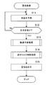
- Warning processing is a process of determining in advance the traveling risk at a specific position in or around the intersection when the vehicle travels at the intersection, and issuing a warning as necessary.
- FIG. 2 is a flowchart of the warning process. This process is realized by the system controller 20 (hereinafter, also simply referred to as "controller 20") of the navigation device 1 shown in FIG. 1 executing a prepared program.
- controller 20 the system controller 20 (hereinafter, also simply referred to as "controller 20") of the navigation device 1 shown in FIG. 1 executing a prepared program.
- the controller 20 predicts turning of the vehicle at the intersection (step S11). That is, the controller 20 predicts whether the vehicle equipped with the navigation device 1 turns left or right at the nearest intersection. There are several conceivable prediction methods for turning left and right. In the first method, when the travel route to the destination is set, the controller 20 predicts whether or not to turn the nearest intersection on the basis of the set travel route.
- the controller 20 predicts a left / right turn based on the presence / absence of an instruction to a blinker (a direction indicator) of the vehicle and the current position of the vehicle. Specifically, when the driver issues a direction instruction to the right or left while the vehicle is traveling on a one-lane road, the controller 20 predicts that the vehicle will turn right or left in the direction for which the direction instruction is issued. Do. In the third method, the controller 20 predicts turning based on the map information and the current position of the vehicle. Specifically, when the vehicle is traveling on a right turn lane or a left turn lane on a certain road, the controller 20 predicts that the vehicle will turn right or left.
- the above first to third methods can be used in any combination.
- step S12 If it is not predicted that turning will be performed (step S12: No), the controller 20 repeats step S11. On the other hand, when it is predicted that turning to the left and right will be performed (step S12: Yes), the controller 20 performs trajectory prediction processing (step S13).
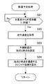
- the track prediction process is a process of predicting a track when the vehicle travels at the intersection, and more specifically, is a process of calculating a relaxation curve indicating the track of the vehicle.
- FIG. 3 shows a flowchart of trajectory prediction processing.
- the controller 20 determines whether the vehicle has reached a predetermined distance from the nearest intersection (step S21).
- the controller 20 acquires the traveling speed of the vehicle (step S22).
- the controller 20 acquires the current traveling speed of the vehicle, and uses the acquired speed as the traveling speed in the intersection. That is, it is assumed that the vehicle travels through the intersection while maintaining the traveling speed.
- the controller 20 may also acquire the change rate of the traveling speed of the vehicle up to that point, and predict the traveling speed in the intersection in consideration of the acquired change rate. Specifically, the controller 20 accumulates traveling speed data before entering an intersection, and calculates a rate of change in traveling speed. Then, the traveling speed in the intersection is predicted by adding the rate of change to the traveling speed acquired in step S22. Since the vehicle usually decelerates as it approaches an intersection, the change in traveling speed decelerates. Therefore, in consideration of the rate of change of the traveling speed, the controller 20 usually predicts the speed lower than the traveling speed acquired in step S22 as the traveling speed in the intersection.
- the controller 20 When the traveling speed in the intersection is predicted, the controller 20 next sets the start point and the end point of the predicted track (step S23).
- the predicted track is a track predicted to be drawn when the vehicle turns left and right in the intersection. Specifically, the controller 20 sets the start point and the end point of the predicted trajectory based on the current position of the vehicle, the map information (shape of the intersection) and the traveling speed.
- the controller 20 determines the initial position of the start point of the predicted trajectory based on the current position of the vehicle and road information (such as the direction of the road, the number of lanes, and the road width) of the road on which the vehicle is traveling. Set the position. For example, the controller 20 sets the point where the vehicle enters an intersection on the road on which the vehicle is traveling as the initial position of the start point of the predicted trajectory. Since the range of the intersection can be defined based on the center position (coordinates) of the intersection and the width of the road that intersects the road being traveled, the point at which the currently traveling road intersects the intersection range is determined , This can be a starting point.
- the controller 20 sets the initial position of the end point of the predicted trajectory based on the road information (the direction of the road, the number of lanes, the road width, etc.) of the road after leaving the intersection. For example, the controller 20 sets the point at which the vehicle leaves the intersection on the road on which the vehicle turns to the left or right as the initial position of the end point of the predicted trajectory.
- the range of the intersection can be defined based on the center position (coordinates) of the intersection and the width of the road crossing the road in which it is traveling, The point of intersection can be determined and taken as the end point.
- FIG. 4A shows a setting example of the start point and the end point of the predicted trajectory when the vehicle is traveling at the standard speed.
- the vehicle position mark 101 the vehicle enters an intersection from the lower side in the figure, and turns right at the intersection.
- a point 103 where the vehicle enters the intersection is set as an initial position of the start point, and a point 104 where the vehicle after the right turn leaves the intersection is set as an initial position of the end point.
- the start and end points of the predicted trajectory are set at positions corresponding to the case where the vehicle travels at an intersection at a standard speed.
- the start point and the end point of the predicted trajectory are set on the outer periphery of the range of the intersection, but may instead be set at a position away from the intersection by a predetermined distance.
- the start point and the end point of the predicted trajectory may be set at a point away from the intersection node in the map information by a predetermined distance.
- the positions of the start point and the end point of the predicted trajectory may be stored in advance in the map information.
- the controller 20 next follows the directions of the respective roads from the initial positions of the start point and the end point according to the traveling speed of the vehicle predicted in step S22. To correct. Specifically, the controller 20 moves the start point closer to the intersection and the end point farther to the intersection as the traveling speed increases. This is because the higher the traveling speed, the smaller the turn of the vehicle becomes effective, and the vehicle can not pass through the intersection unless it is a large turn. In this case, as the driver's driving operation, it is necessary to start turning the steering wheel from the near side and finish moving the steering wheel further from the steering wheel. FIG.
- FIG. 4B shows an example of correcting the start point and the end point of the predicted trajectory when the speed of the vehicle exceeds the standard speed.
- the start point 103 is moved to the front side of the intersection as shown by arrow 107, and the end point 104 is farther than the intersection as shown by arrow 108. Have been moved to the side.
- the start point and the end point of the predicted trajectory are appropriately corrected.
- the initial position and the correction amount of the start point and the end point of the predicted trajectory are the actual positions of the driver's steering wheel start position and return end position based on experimental results obtained by examining actual vehicle behavior. It is good to set appropriately so as to approach.
- the start point and the end point of the predicted trajectory may be corrected based on the actual traveling tendency of the driver. Specifically, based on the driver's past travel history data, the driver's driving tendency in turning to the left or right, specifically, the position at which the steering wheel has started to turn or the position at which the steering wheel has been returned Whether or not the steering wheel has begun to be cut may be analyzed, and the start point and the end point of the predicted trajectory may be corrected based on the result. This makes it possible to obtain a predicted trajectory that is suitable for drivers of various traveling tendencies, such as a driver who starts turning the steering wheel early when turning left or right at an intersection, and a driver who is slow to start turning the steering wheel.
- the controller 20 calculates a clothoid curve passing through the start point and the end point set in step S23 (step S24).
- the clothoid curve is an example of the relaxation curve, and indicates the trajectory that the vehicle travels when the steering wheel is turned at a constant angular velocity.
- the trajectory of the vehicle will include a clothoid curve. That is, here, the controller 20 predicts the trajectory of the vehicle when the driver performs a natural driving operation.
- the clothoid curve here includes a track drawn by the vehicle when the driver turns the steering wheel, and a track drawn by the vehicle when the steering wheel is returned.
- the clothoid curve when the angle of intersection is 90 degrees, it is a clothoid curve when turning the steering wheel at a constant speed, typically until the direction of the vehicle turns 45 degrees, and thereafter the steering wheel is returned at a constant speed It becomes a clothoid curve when Furthermore, assuming that the traveling speed of the vehicle is constant, the clothoid curve when the steering wheel is turned and the clothoid curve when the steering wheel is turned back have a symmetrical shape. That is, by assuming that the traveling speed of the vehicle at the intersection is constant, it is possible to uniquely calculate a clothoid curve passing through the start point and the end point of the set predicted trajectory.
- the steering angle is constant between the clothoid curve when turning the steering wheel at a constant speed and the clothoid curve when turning the steering wheel at a constant speed.
- the length of the arc to be inserted may be appropriately set according to the shape of the intersection or the like.
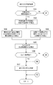
- step S14 the controller 20 performs a traveling risk determination process.
- 5 and 6 are flowcharts of the traveling risk determination process.
- the controller 20 determines whether or not there is an opposite lane in the intersection based on the road information in the vicinity of the intersection (step S31). If there is no oncoming lane (step S31: No), the process proceeds to step S38 described later.
- step S31 when there is an opposite lane (step S31: Yes), the controller 20 detects a determination position P1 at which the predicted trajectory intersects the opposite lane (step S32).
- FIG. 7A shows an example of the determination position P1.
- the controller 20 detects the determination position P1 at which the predicted trajectory 102 intersects the oncoming lane 110.
- the controller 20 calculates the lateral acceleration Ga1 generated in the vehicle at the determination position P1 when the current traveling speed is maintained (step S33).
- the lateral acceleration Ga1 generated in the vehicle at the determination position P1 on the predicted track 102 is determined by the following equation.
- Ga1 (current speed) 2 ⁇ A 2 / L (2)
- “A” is a clothoid parameter obtained in step S24 of the trajectory prediction process
- “L” is a traveling distance from the start point on the predicted trajectory 102 to the determination position P1.
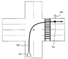
- FIG. 8 shows the acceleration at the determination position P1.
- the lateral acceleration Ga1 is a vector in a direction perpendicular to the traveling direction of the vehicle at the determination position P1.
- the controller 20 calculates the negative acceleration Gb1 generated on the vehicle when the vehicle suddenly stops at the determination position P1 (step S34). Specifically, the controller 20 stops the vehicle at the determination position P1 based on the traveling speed of the vehicle, the distance from the start point on the predicted track 102 to the determination position P1, the braking characteristic of the vehicle, etc. Determine the negative acceleration Gb1 necessary for decelerating to 0). Note that this negative acceleration may be obtained by preparing in advance a table or the like according to the traveling speed of the vehicle, the distance to the determination position P1, the weight of the vehicle, etc., and referring to the table. . As shown in FIG. 8, the negative acceleration Gb1 is a vector directed in the direction opposite to the traveling direction of the vehicle at the determination position P1.
- the controller 20 calculates a combined acceleration Gc1 of the lateral acceleration Ga1 and the negative acceleration Gb1 (step S35).
- the composite acceleration Gc1 is calculated by determining a composite vector of the lateral acceleration Ga1 and the negative acceleration Gb1 at the determination position P1.
- the synthetic acceleration Gc1 is calculated as an index for comprehensive evaluation of the risk by the lateral acceleration Ga1 and the risk by the negative acceleration Gb1.
- the lateral acceleration Ga1 it is possible to determine the risk in terms of whether the vehicle can stably travel in the intersection.
- the negative acceleration Gb1 it is possible to determine the risk in terms of whether the vehicle can be safely stopped when an oncoming vehicle arrives at the intersection.
- the controller 20 determines whether the calculated synthetic acceleration Gc1 is larger than a predetermined reference value (step S36). When synthetic acceleration Gc1 is less than a reference value (Step S36: No), processing progresses to Step S38. On the other hand, when the synthetic acceleration Gc1 is larger than the reference value (step S36: Yes), the controller 20 determines that there is a traveling risk (step S37). Then, the process returns to the main routine of FIG.
- the reference value is determined in advance based on information obtained from an experiment using a vehicle, a situation of an accident that has actually occurred, and the like. The reference value may be changed according to the road surface condition, the road slope, the type of the host vehicle (small car / large car) and the like.
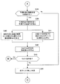
- step S38 the controller 20 determines whether the predicted trajectory passes the pedestrian crossing near the intersection based on the road information near the intersection. When it does not pass the pedestrian crossing (step S38: No), the controller 20 determines that there is no travel risk (step S44), and the process returns to the main routine of FIG.
- the controller 20 detects the determination position P2 which is the position where the predicted trajectory reaches the pedestrian crossing (step S39).
- FIG. 7B shows an example of the determination position P2.
- the controller 20 detects a determination position P2 at which the predicted trajectory 102 intersects the pedestrian crossing 111.
- the position where the predicted track intersects the oncoming lane and the pedestrian crossing is regarded as the determination position as a position where the possibility of coming into contact with another moving object is relatively high in the vicinity of the intersection.
- a two-way road or the like which has a relatively high possibility of coming into contact with another moving object, may be the target of the determination position.
- the controller 20 calculates the lateral acceleration Ga2 generated in the vehicle at the determination position P2 when the current traveling speed is maintained (step S40). Specifically, the controller 20 obtains the lateral acceleration Ga2 generated in the vehicle at the determination position P2 on the predicted track 102 by the above-mentioned equation (2) as in the case of the lateral acceleration Ga1.
- the controller 20 calculates the negative acceleration Gb2 generated on the vehicle when the vehicle suddenly stops at the determination position P2 (step S41). Specifically, the controller 20 determines the traveling speed of the vehicle, the distance from the start point on the predicted track 102 to the judgment position P2, the braking characteristic of the vehicle, etc., as in the case of the above-mentioned negative acceleration Gb1. The negative acceleration Gb2 necessary to stop the vehicle is determined.
- the controller 20 calculates the combined acceleration Gc2 of the lateral acceleration Ga2 and the negative acceleration Gb2 similarly to the above-described combined acceleration Gc1 (step S42).
- the synthetic acceleration Gc2 is calculated as an index for comprehensive evaluation of the risk by the lateral acceleration Ga2 and the risk by the negative acceleration Gb2.
- the lateral acceleration Ga2 it is possible to determine the risk in terms of whether the vehicle can stably travel in the intersection.
- the negative acceleration Gb2 it is possible to determine the risk in terms of whether the vehicle can be safely stopped when a pedestrian or the like is on the pedestrian crossing.
- the controller 20 If it is determined that there is a traveling risk by the traveling risk determination processing, the controller 20 outputs a warning for notifying the driver of a danger (step S15). This warning is given by sound, light, vibration or a combination thereof. Then, the warning process ends.
- Modification 1 Although the above embodiment is described taking the case where the vehicle turns right at the intersection, the present invention is also applicable to the case where the vehicle turns left at the intersection. In addition, in the case where the intersection has a complicated shape such as a three way road, a five way road, etc., the present invention is similarly applicable to a case where the vehicle turns to the diagonally forward or backward road.
- the controller 20 may set the end point of the predicted trajectory for each travelable lane, calculate the predicted trajectory, and perform risk determination on each predicted trajectory.
- the controller 20 may issue a warning when there is at least one predicted trajectory determined to have the travel risk.
- the risk judgment may be performed on the predicted orbit which becomes the smallest among the predicted orbits of each lane, and a warning may be issued according to the judgment result.
- an end point may be set for each lane as described above to calculate a predicted trajectory, and risk determination may be performed on each predicted trajectory.
- the controller 20 may issue a warning when there is at least one predicted trajectory determined to have the travel risk.
- the risk judgment may be performed on the predicted orbit which becomes the smallest among the predicted orbits of each lane, and a warning may be issued according to the judgment result.
- the controller 20 may set the position of the detected other vehicle or pedestrian as the determination position, and may determine the traveling risk at the determination position. For example, as shown in FIG. 10, when it is detected that the pedestrian 105 is present at a position ahead of the pedestrian crossing on the road on which the vehicle is turned right, the controller 20 can detect the pedestrian 105 Position is set as the determination position Px.
- the travel risk may be determined by calculating the lateral acceleration or the negative acceleration at the determination position Px, and a necessary warning may be issued. Also, in this way, when other vehicles or pedestrians are actually detected based on surrounding traffic information and obstacle detection, and it is judged that there is a traveling risk by the traveling risk judgment, in addition to the output of the warning A process may be performed to automatically brake and stop the vehicle.
- a clothoid curve is used as a relaxation curve indicating the trajectory of a vehicle in an intersection, but the application of the present invention is not limited to this, and, for example, broth relaxation curve, sine curve, sine half wavelength Predicted trajectories may be determined using other known relaxation curves, such as decreasing curves, cubic curves, and the like.
- the type and characteristics (parameters) of the relaxation curve used in the trajectory prediction process may be changed based on the tendency of the traveling trajectory of the driver.
- the track drawn during actual driving often differs depending on the driver's habit and driving tendency. For example, (a) drivers who tend to turn relatively large, (b) drivers who tend to turn relatively small, (c) they enter an intersection at a relatively high speed, and tend to turn while bulging out in the second half.
- drivers with various driving tendencies such as drivers, (d) drivers who enter an intersection at a relatively low speed, and tend to turn early and exit the intersection in a straight line.
- the driver is presented with a choice of driving tendency such as the above (a) to (d), and the driver is made to select one that conforms to his own driving tendency and conforms to the selected driving tendency.
- the trajectory prediction process may be performed using at least one of a relaxation curve and a characteristic (parameter) prepared in advance as one.
- the driving tendency when the driver turns the intersection is referred to by referring to the actual driving history data of the driver.
- the relaxation curve and the characteristic to be used may be changed based on the analyzed and obtained traveling tendency.
- the traveling tendency in turning of the driver is extracted, and the type and characteristics of the relaxation curve are changed based on the acquired traveling tendency. Is desirable. As a result, it is possible to obtain a predicted track that matches the traveling tendency of the driver, not only at the intersection where the driver has actually traveled in the past, but also at the intersection where the driver travels for the first time.
- the position where the predicted trajectory intersects the oncoming lane or the pedestrian crossing is used as the determination position for determining the traveling risk, and in the fourth modification, the position of another moving object detected based on surrounding traffic information or obstacle detection. Is the judgment position.
- the determination position may be corrected according to the driver information, specifically the driving skill level or the like. For a driver who is determined to have a driving skill level equal to or lower than a certain level, the safety can be enhanced by performing correction such that the determination position is moved to the near side.
- the driving skill level of the driver can be estimated by analysis of past driving history data of the driver. Also, the driver may evaluate and set his / her driving skill level.
- an attribute (age, sex, driving history, etc.) of the driver, a traveling tendency of the driver, or the like may be used as an indication of the driving skill level indirectly.
- the driver may be able to set the correction amount of the determination position. For example, a driver who is not very confident in driving technology may be set to correct the determination position a predetermined distance (for example, several meters) before the normal travel risk determination position.
- a predetermined distance for example, several meters
- the reference value used for determining the traveling risk may be corrected. Specifically, in accordance with the driver information, the reference value (see steps S36 and S43) used in the traveling risk determination process is corrected. For example, for a driver whose driving skill level is estimated to be lower than or equal to a certain level based on the driver information, the driving risk is determined using a reference value lower than a normally used reference value. This makes it easy to output a warning to a driver with a low driving skill level.
- the system may be configured of an on-board device such as the display unit 40 or the audio output unit 50, and an external device (such as a server).
- the in-vehicle device transmits various information to the server via the network, the server performs at least one of trajectory prediction processing and traveling risk determination processing, and transmits the processing result of the server to the in-vehicle device.
- the on-vehicle apparatus and the external apparatus may execute the traveling risk determination process at the time of turning to the right of the intersection in cooperation with each other. Which of the series of processes each of the in-vehicle apparatus and the external apparatus executes may be set as appropriate.
- the navigation device 1 may be provided to a vehicle or may be a portable terminal.
- Navigation device 22 CPU 32 obstacle detection unit 101 vehicle position mark 102 predicted trajectory 103 starting point 104 end point P1, P2, Px determination position
Landscapes
- Engineering & Computer Science (AREA)
- Automation & Control Theory (AREA)
- Transportation (AREA)
- Mechanical Engineering (AREA)
- Physics & Mathematics (AREA)
- General Physics & Mathematics (AREA)
- Remote Sensing (AREA)
- Radar, Positioning & Navigation (AREA)
- Traffic Control Systems (AREA)
- Computer Networks & Wireless Communication (AREA)
- Signal Processing (AREA)
- Navigation (AREA)
- Control Of Driving Devices And Active Controlling Of Vehicle (AREA)
Abstract
判定装置は、移動体が交差点を実際に右左折走行する前に走行リスクを判定する。具体的に、判定装置は、移動体の移動速度に関する速度情報を取得するとともに、交差点の形状を含む交差点情報を取得する。次に、判定装置は、速度情報及び交差点情報に基づき、移動体が交差点を走行する際の走行軌道を予測する。そして、判定装置は、走行軌道に基づき走行リスクを判定する。
Description
本発明は、交差点の右左折時におけるリスクを判定する技術に関する。
カーブにおける車両の走行を安定化する技術が知られている。例えば、特許文献1は、地図情報に基づくカーブ形状と現在の車速とに基づいて、カーブを走行中に車両に生じる横加速度を算出し、該横加速度に基づいて車両がカーブを安定して通過できるかをカーブ進入前後において判定し、判定結果に応じて車両安定化制御装置の設定を切り替えることを記載している。
カーブと比較して、交差点を通過する場合に車両が走行する軌道の自由度は高く、車両は様々な軌道で走行しうる。交差点の右左折においては、車両の軌道次第で走行リスクが変化するため、交差点の走行前に走行リスクを判定することは難しかった。
本発明の課題としては上記のものが一例として挙げられる。本発明は、車両が交差点を走行する際の軌道を適切に予測し、走行リスクを判定することを目的とする。
請求項に記載の発明は、移動体が交差点を実際に右左折走行する前に走行リスクを判定する判定装置であって、前記移動体の移動速度に関する速度情報を取得する第1取得部と、前記交差点の形状を含む交差点情報を取得する第2取得部と、前記速度情報及び前記交差点情報に基づき、前記移動体が交差点を走行する際の走行軌道を予測する予測部と、前記走行軌道に基づき前記走行リスクを判定する判定部と、を備えることを特徴とする。
他の請求項に記載の発明は、移動体が交差点を実際に右左折走行する前に走行リスクを判定する判定装置により実行される判定方法であって、前記移動体の移動速度に関する速度情報を取得する第1取得工程と、前記交差点の形状を含む交差点情報を取得する第2取得工程と、前記速度情報及び前記交差点情報に基づき、前記移動体が交差点を走行する際の走行軌道を予測する予測工程と、前記走行軌道に基づき前記走行リスクを判定する判定工程と、を備えることを特徴とする。
他の請求項に記載の発明は、コンピュータを備え、移動体が交差点を実際に右左折走行する前に走行リスクを判定する判定装置により実行されるプログラムであって、前記移動体の移動速度に関する速度情報を取得する第1取得部、前記交差点の形状を含む交差点情報を取得する第2取得部、前記速度情報及び前記交差点情報に基づき、前記移動体が交差点を走行する際の走行軌道を予測する予測部、前記走行軌道に基づき前記走行リスクを判定する判定部、として前記コンピュータを機能させることを特徴とする。
本発明の1つの好適な実施形態では、移動体が交差点を実際に右左折走行する前に走行リスクを判定する判定装置は、前記移動体の移動速度に関する速度情報を取得する第1取得部と、前記交差点の形状を含む交差点情報を取得する第2取得部と、前記速度情報及び前記交差点情報に基づき、前記移動体が交差点を走行する際の走行軌道を予測する予測部と、前記走行軌道に基づき前記走行リスクを判定する判定部と、を備える。
上記の判定装置は、移動体が交差点を実際に右左折走行する前に走行リスクを判定する。判定装置は、移動体の移動速度に関する速度情報を取得するとともに、交差点の形状を含む交差点情報を取得する。次に、判定装置は、速度情報及び交差点情報に基づき、移動体が交差点を走行する際の走行軌道を予測する。そして、判定装置は、走行軌道に基づき走行リスクを判定する。移動体が交差点を走行する際の走行軌跡を予測することにより、走行リスクを正確に判定することが可能となる。
上記の判定装置の一態様では、前記予測部は、前記速度情報及び前記交差点情報に基づいて前記走行軌道の始点及び終点を設定し、前記始点と前記終点の間の前記走行軌道を、緩和曲線を含む曲線として予測する。これにより、実際の走行軌道に近い走行軌道を予測することが可能となる。
上記の判定装置の他の一態様では、前記予測部は、前記交差点情報に基づいて特定した前記始点及び前記終点の位置を、前記速度情報に応じて補正して設定する。これにより、移動体の速度に応じた適切な始点及び終点の位置を設定することができる。好適には、前記予測部は、前記速度情報が速い速度を示す程、前記始点及び前記終点の位置を前記交差点から離れる方向に補正する。
好適な例では、前記緩和曲線はクロソイド曲線である。
上記の判定装置の他の一態様は、前記走行軌道上の判定位置を設定する設定部を備え、前記判定部は、前記判定位置において前記移動体の横方向に向けて生じる加速度である横加速度を予測し、当該横加速度に基づいて前記移動体の右左折走行に対する走行リスクを判定する。これにより、特定の判定位置における走行リスクを判定することが可能となる。好適な例では、前記設定部は、前記交差点内の対向車線又は前記交差点内の横断歩道と、前記走行軌道とが交差する位置を前記判定位置として設定する。
本発明の他の好適な実施形態では、移動体が交差点を実際に右左折走行する前に、走行リスクを判定する判定装置により実行される判定方法は、前記移動体の移動速度に関する速度情報を取得する第1取得工程と、前記交差点の形状を含む交差点情報を取得する第2取得工程と、前記速度情報及び前記交差点情報に基づき、前記移動体が交差点を走行する際の走行軌道を予測する予測工程と、前記走行軌道に基づき前記走行リスクを判定する判定工程と、を備える。この方法でも、移動体が交差点を走行する際の走行軌跡を予測することにより、走行リスクを正確に判定することが可能となる。
本発明の他の好適な実施形態では、コンピュータを備え、移動体が交差点を実際に右左折走行する前に走行リスクを判定する判定装置により実行されるプログラムは、前記移動体の移動速度に関する速度情報を取得する第1取得部、前記交差点の形状を含む交差点情報を取得する第2取得部、前記速度情報及び前記交差点情報に基づき、前記移動体が交差点を走行する際の走行軌道を予測する予測部、前記走行軌道に基づき前記走行リスクを判定する判定部、として前記コンピュータを機能させる。このプログラムをコンピュータで実行することにより、上記の判定装置を実現することができる。このプログラムは、記憶媒体に記憶して取り扱うことができる。
以下、図面を参照して本発明の好適な実施例について説明する。
[ナビゲーション装置]
図1は、本発明の実施例に係るナビゲーション装置1の構成を示す。図1に示すように、ナビゲーション装置1は、自立測位装置10、GPS受信機18、システムコントローラ20、ディスクドライブ31、障害物検出部32、データ記憶ユニット36、通信用インタフェース37、通信装置38、表示ユニット40、音声出力ユニット50、入力装置60を備える。
[ナビゲーション装置]
図1は、本発明の実施例に係るナビゲーション装置1の構成を示す。図1に示すように、ナビゲーション装置1は、自立測位装置10、GPS受信機18、システムコントローラ20、ディスクドライブ31、障害物検出部32、データ記憶ユニット36、通信用インタフェース37、通信装置38、表示ユニット40、音声出力ユニット50、入力装置60を備える。
システムコントローラ20、ディスクドライブ31、障害物検出部32、データ記憶ユニット36、通信用インタフェース37、表示ユニット40、音声出力ユニット50及び入力装置60は、バスライン30を介して相互に接続されている。
自立測位装置10は、加速度センサ11、角速度センサ12及び距離センサ13を備える。加速度センサ11は、例えば圧電素子からなり、車両の加速度を検出し、加速度データを出力する。角速度センサ12は、例えば振動ジャイロからなり、車両の方向転換時における車両の角速度を検出し、角速度データ及び相対方位データを出力する。距離センサ13は、車両の車輪の回転に伴って発生されているパルス信号からなる車速パルスを計測する。
GPS受信機18は、複数のGPS衛星から、測位用データを含む下り回線データを搬送する電波19を受信する。測位用データは、緯度及び経度情報等から車両の絶対的な位置(以後、「現在位置」とも呼ぶ。)を検出するために用いられる。
システムコントローラ20は、インタフェース21、CPU(Central Processing Unit)22、ROM(Read Only Memory)23及びRAM(Random Access Memory)24を含んでおり、ナビゲーション装置1全体の制御を行う。
インタフェース21は、加速度センサ11、角速度センサ12、距離センサ13、GPS受信機18とのインタフェース動作を行う。そして、これらから、車速パルス、加速度データ、相対方位データ、角速度データ、GPS測位データ、絶対方位データ等をシステムコントローラ20に入力する。
CPU22は、システムコントローラ20全体を制御する。ROM23は、システムコントローラ20を制御する制御プログラム等が格納された図示しない不揮発性メモリ等を有する。RAM24は、入力装置60を介して使用者により予め設定された経路データ等の各種データを読み出し可能に格納したり、CPU22に対してワーキングエリアを提供したりする。
ディスクドライブ31は、図示しないCD、DVDなどから音楽や映像のデータを読みだし、表示ユニット40や音声出力ユニット50へ出力する。
障害物検出部32は、例えばカメラ、Lidar(Light Detection and Ranging)などからなり、車両の周辺、特に車両の前方に存在する障害物を検出する。障害物には、建物などの地物の他、車両や歩行者などの移動体が含まれる。
データ記憶ユニット36は、例えば、HDDなどにより構成され、地図データなどのナビゲーション処理に用いられる各種データを記憶する。通信装置38は、ネットワークを介してサーバ7との間で無線通信を行う。また、通信装置38は、路車間通信や車車間通信を利用して車両周辺の交通状況に関する周辺交通情報を受信する。
表示ユニット40は、システムコントローラ20の制御の下、各種表示データをディスプレイなどの表示装置に表示する。表示ユニット40は、システムコントローラ20によってデータ記憶ユニット36から読み出された地図データなどを表示画面上に表示する。表示ユニット40は、バスライン30を介してCPU22から送られる制御データに基づいて表示ユニット40全体の制御を行うグラフィックコントローラ41と、VRAM(Video RAM)等のメモリからなり即時表示可能な画像情報を一時的に記憶するバッファメモリ42と、グラフィックコントローラ41から出力される画像データに基づいて、液晶等のディスプレイ44を表示制御する表示制御部43と、ディスプレイ44とを備える。ディスプレイ44は、画像表示部として機能し、例えば対角5~10インチ程度の液晶表示装置等からなり、車内のフロントパネル付近に装着される。
音声出力ユニット50は、システムコントローラ20の制御の下、ディスクドライブ31又はRAM24等からバスライン30を介して送られる音声デジタルデータのD/A(Digital to Analog)変換を行うD/Aコンバータ51と、D/Aコンバータ51から出力される音声アナログ信号を増幅する増幅器(AMP)52と、増幅された音声アナログ信号を音声に変換して車内に出力するスピーカ53とを備えて構成されている。
入力装置60は、各種コマンドやデータを入力するための、キー、スイッチ、ボタン、リモコン、音声入力装置等から構成されている。入力装置60は、車内に搭載された当該車載用電子システムの本体のフロントパネルやディスプレイ44の周囲に配置される。また、ディスプレイ44がタッチパネル方式の場合、ディスプレイ44の表示画面上に設けられたタッチパネルも入力装置60として機能する。
上記の構成において、システムコントローラ20は本発明の第1取得部、第2取得部、予測部、判定部及び設定部の一例である。
[警告処理]
次に、本実施例による警告処理について説明する。警告処理は、車両が交差点を走行する際に、交差点内又は周辺の特定の位置における走行リスクを事前に判定し、必要に応じて警告を発する処理である。
次に、本実施例による警告処理について説明する。警告処理は、車両が交差点を走行する際に、交差点内又は周辺の特定の位置における走行リスクを事前に判定し、必要に応じて警告を発する処理である。
図2は、警告処理のフローチャートである。この処理は、図1に示すナビゲーション装置1のシステムコントローラ20(以下、単に「コントローラ20」とも呼ぶ。)が、予め用意されたプログラムを実行することにより実現される。
まず、コントローラ20は、交差点における車両の右左折を予測する(ステップS11)。即ち、コントローラ20は、ナビゲーション装置1を搭載した車両が、直近の交差点で右左折するか否かを予測する。右左折の予測方法としてはいくつか考えられる。第1の方法では、コントローラ20は、目的地までの走行ルートが設定されている場合に、設定された走行ルートに基づいて直近の交差点を右左折するか否かを予測する。
第2の方法では、コントローラ20は、車両のウィンカー(方向指示器)への指示の有無と、車両の現在位置とに基づいて右左折を予測する。具体的には、車両が片側一車線道路を走行中に運転者により右又は左への方向指示が出された場合、コントローラ20は、方向指示が出された方向へ車両が右折又は左折すると予測する。第3の方法では、コントローラ20は、地図情報と車両の現在位置とに基づき右左折を予測する。具体的には、ある道路の右折専用レーン又は左折専用レーンを車両が走行している場合、コントローラ20は車両が右折又は左折すると予測する。なお、上記の第1~第3の方法は任意に組み合わせて使用することができる。
右左折が行われると予測されなかった場合(ステップS12:No)、コントローラ20はステップS11を繰り返す。一方、右左折が行われると予測された場合(ステップS12:Yes)、コントローラ20は軌道予測処理を行う(ステップS13)。
軌道予測処理は、車両が交差点を右左折走行する際の軌道を予測する処理であり、具体的には車両の軌道を示す緩和曲線を算出する処理である。図3は、軌道予測処理のフローチャートを示す。まず、コントローラ20は、車両が直近の交差点から所定距離に到達したか否かを判定する(ステップS21)。
車両が交差点から所定距離に到達した場合(ステップS21:Yes)、コントローラ20は、車両の走行速度を取得する(ステップS22)。この場合、基本的には、コントローラ20は車両のそのときの走行速度を取得し、取得した速度を、交差点内の走行速度と仮定して利用する。即ち、車両がその走行速度を維持したまま交差点を走行、通過するものと仮定する。
但し、コントローラ20は、それまでの車両の走行速度の変化率も取得しておき、取得した変化率を加味して交差点内の走行速度を予測しても良い。具体的には、コントローラ20は交差点への進入前の走行速度データを蓄積しておき、走行速度の変化率を算出する。そして、ステップS22で取得した走行速度に、その変化率を加味して交差点内の走行速度を予測する。通常、車両は交差点に近づくにつれて減速するため、走行速度の変化は減速となる。よって、走行速度の変化率を考慮した場合、コントローラ20は通常はステップS22で取得した走行速度よりも低い速度を交差点内の走行速度と予測することになる。
交差点内の走行速度が予測されると、次にコントローラ20は、予測軌道の始点と終点を設定する(ステップS23)。予測軌道とは、車両が交差点内を右左折する際に描くと予測される軌道である。詳しくは、コントローラ20は、車両の現在位置、地図情報(交差点の形状)及び走行速度に基づいて、予測軌跡の始点と終点を設定する。
具体的には、まずコントローラ20は、車両の現在位置と、車両が走行している道路の道路情報(道路の方向、車線数、道幅(幅員)など)に基づいて、予測軌道の始点の初期位置を設定する。例えば、コントローラ20は、車両が走行中の道路上で交差点に進入する地点を予測軌道の始点の初期位置に設定する。交差点の範囲は、交差点の中心位置(座標)と、走行中の道路と交差する道路の幅員とに基づいて規定することができるので、現在走行中の道路が交差点の範囲と交わる地点を決定し、これを始点とすることができる。
次に、コントローラ20は、交差点を退出した先の道路の道路情報(道路の方向、車線数、道幅など)に基づいて、予測軌道の終点の初期位置を設定する。例えば、コントローラ20は、車両が右左折した先の道路上で交差点を退出する地点を予測軌道の終点の初期位置に設定する。前述のように、交差点の範囲は、交差点の中心位置(座標)と、走行中の道路と交差する道路の幅員に基づいて規定することができるので、右左折した先の道路が交差点の範囲と交わる地点を決定し、これを終点とすることができる。
図4(A)は、車両が標準速度で走行している場合の予測軌道の始点及び終点の設定例を示す。自車位置マーク101に示すように、車両は図中の下側から交差点に進入し、交差点を右折するものとする。車両が交差点に進入する地点103が始点の初期位置として設定され、右折後の車両が交差点から退出する地点104が終点の初期位置として設定される。
予測軌道の始点及び終点は、車両が標準的な速度で交差点を走行する場合に対応する位置に設定される。なお、上記の例では、予測軌道の始点及び終点は、交差点の範囲の外周上に設定されているが、その代わりに、交差点から所定距離だけ離れた位置に設定されてもよい。具体的には、予測軌道の始点及び終点は、地図情報における交差点ノードから所定距離離れた地点に設定してもよい。また、地図情報中に、予め予測軌道の始点及び終点の位置を記憶しておいてもよい。
こうして、予測軌道の始点及び終点の初期位置が設定されると、次にコントローラ20は、ステップS22で予測された車両の走行速度に応じて、始点及び終点の初期位置を各道路の方向に沿って補正する。具体的には、コントローラ20は、走行速度が速いほど、始点を交差点のより手前側に、終点を交差点のより遠方側に移動する。これは、走行速度が速くなるほど、車両の小回りが効かなくなり、大回りの軌道でないと交差点を通過できなくなるからである。この場合、運転者の運転操作としては、より手前からハンドルを切り始め、より遠方でハンドルを戻し終える必要が生じる。図4(B)は、車両の速度が標準速度を超えている場合に予測軌道の始点及び終点を補正する例を示す。この例では、ステップS22で予測された車両の走行速度が標準速度より速いため、矢印107で示すように始点103が交差点より手前側に移動され、矢印108で示すように終点104が交差点より遠方側に移動されている。
こうして、車両の走行速度に応じて、予測軌道の始点及び終点が適切に補正される。なお、予測軌道の始点及び終点の初期位置及び補正量は、実際の車両の挙動を調べた実験結果などに基づいて、運転者によるハンドルの切り始めの位置及び戻し終わりの位置が実際の位置と近づくように適宜設定するとよい。
なお、上記のような走行速度に基づく補正の代わりに又はそれに加えて、実際の運転者の走行傾向に基づいて予測軌道の始点及び終点を補正してもよい。具体的には、運転者の過去の走行履歴データに基づいて、その運転者の右左折における走行傾向、具体的にはハンドルを切り始めた位置やハンドルを戻し終わった位置(交差点の何m手間でハンドルを切り始めたかなど)を分析し、その結果に基づいて予測軌道の始点及び終点を補正してもよい。これにより、交差点を右左折する際に早めにハンドルを切り始める運転者、ハンドルを切り始めるのが遅い運転者など、様々な走行傾向の運転者に適合した予測軌道を得ることが可能となる。
次に、コントローラ20は、ステップS23で設定された始点及び終点を通過するクロソイド曲線を算出する(ステップS24)。クロソイド曲線は、緩和曲線の一例であり、ハンドルを一定の角速度で回したときに車両が進む軌道を示す。通常、カーブにおいて運転者がスムーズなハンドル操作を行った場合、車両の軌道はクロソイド曲線を含むようになる。即ち、ここでは、コントローラ20は、運転者が自然な運転操作を行った場合の車両の軌道を予測する。
詳しくは、ここでのクロソイド曲線は、運転者がハンドルを切っていく際に車両が描く軌道と、ハンドルを戻していく際に車両が描く軌道とを含む。例えば、交差点の角度が90度である場合、典型的には車両の方向が45度回転するまでがハンドルを一定速度で切っていくときのクロソイド曲線であり、それ以降がハンドルを一定速度で戻していくときのクロソイド曲線となる。さらに、車両の走行速度が一定であると仮定すると、ハンドルを切っていくときのクロソイド曲線と、ハンドルを戻していくときのクロソイド曲線とは線対称な形状となる。即ち、交差点内での車両の走行速度が一定であると仮定することで、設定された予測軌道の始点及び終点を通るクロソイド曲線を一意に算出することができる。
なお、右左折の角度が鋭角となる交差点では、ハンドルを一定速度で切っていくときのクロソイド曲線と、ハンドルを一定速度で戻していくときのクロソイド曲線との間に、ハンドルの切り角を一定角度で維持したときの軌道となる円弧を挿入しても良い。この場合、挿入する円弧の長さは、交差点の形状などに応じて適宜設定すればよい。
クロソイド曲線の基本式は以下のように与えられる。
R×L=A2 (1)
ここで、「L」は始点(クロソイド始点)から交差点内の任意の位置Pまでの曲線長、「R」は任意の位置Pにおける曲率半径、「A」はクロソイドパラメータ(定数)をそれぞれ示す。クロソイド曲線が一意に決定されれば、それに対応するクロソイドパラメータAが一意に決定する。ステップS23の処理では、コントローラ20は、予測軌道の始点及び終点を通過するクロソイド曲線を描き、そのクロソイドパラメータAを求める。具体的には、クロソイドパラメータAを変化させながら予測軌道の始点及び終点を通過するクロソイド曲線を描き、得られたクロソイド曲線のクロソイドパラメータAを出力する。こうして、図4(A)、(B)に例示する予測軌道102が得られる。クロソイド曲線が算出されると、処理は図2のメインルーチンに戻る。
次に、コントローラ20は、走行リスク判定処理を行う(ステップS14)。図5及び図6は走行リスク判定処理のフローチャートである。図5において、まずコントローラ20は、交差点付近の道路情報に基づいて、交差点内に対向車線があるか否かを判定する(ステップS31)。対向車線が無い場合(ステップS31:No)、処理は後述するステップS38へ進む。
一方、対向車線がある場合(ステップS31:Yes)、コントローラ20は、予測軌道が対向車線と交差する位置である判定位置P1を検出する(ステップS32)。図7(A)は、判定位置P1の例を示す。図7(A)の例では、コントローラ20は、予測軌道102が対向車線110と交差する判定位置P1を検出する。
次に、コントローラ20は、現在の走行速度が維持される場合に判定位置P1で車両に生じる横加速度Ga1を算出する(ステップS33)。予測軌道102上の判定位置P1において車両に生じる横加速度Ga1は、以下の式により求められる。
Ga1=(現在の速度)2×A2/L (2)
ここで、「A」は軌道予測処理のステップS24で得られたクロソイドパラメータであり、「L」は予測軌道102上の始点から判定位置P1までの走行距離である。図8は、判定位置P1における加速度を示す。図8に示すように、横加速度Ga1は、判定位置P1における車両の進行方向に垂直な方向のベクトルとなる。
Ga1=(現在の速度)2×A2/L (2)
ここで、「A」は軌道予測処理のステップS24で得られたクロソイドパラメータであり、「L」は予測軌道102上の始点から判定位置P1までの走行距離である。図8は、判定位置P1における加速度を示す。図8に示すように、横加速度Ga1は、判定位置P1における車両の進行方向に垂直な方向のベクトルとなる。
また、コントローラ20は、判定位置P1で車両が急停止した場合に車両に生じるマイナス加速度Gb1を算出する(ステップS34)。具体的には、コントローラ20は、車両の走行速度、予測軌道102上の始点から判定位置P1までの距離、車両の制動特性などに基づいて、判定位置P1において車両を停止させる(即ち、速度を0まで減速する)ために必要なマイナス加速度Gb1を求める。なお、このマイナス加速度は、車両の走行速度、判定位置P1までの距離、車両の重量などに応じて予め計算したものをテーブルなどとして用意しておき、そのテーブルを参照することにより求めてもよい。図8に示すように、マイナス加速度Gb1は、判定位置P1において車両の走行方向と逆方向に向かうベクトルとなる。
そして、コントローラ20は、横加速度Ga1とマイナス加速度Gb1の合成加速度Gc1を算出する(ステップS35)。具体的には、図8に示すように、判定位置P1における横加速度Ga1と、マイナス加速度Gb1の合成ベクトルを求めることにより、合成加速度Gc1を算出する。ここで、合成加速度Gc1は、横加速度Ga1によるリスクとマイナス加速度Gb1によるリスクの総合評価用の指標として算出される。横加速度Ga1を用いることにより、車両が交差点内を安定して走行できるかという観点でのリスクが判定できる。また、マイナス加速度Gb1を用いることにより、交差点内で対向車が来た場合に車両が安全に停止できるかという観点でのリスクが判定できる。
次に、コントローラ20は、算出された合成加速度Gc1が予め決められた基準値より大きいか否かを判定する(ステップS36)。合成加速度Gc1が基準値未満である場合(ステップS36:No)、処理はステップS38へ進む。一方、合成加速度Gc1が基準値より大きい場合(ステップS36:Yes)、コントローラ20は、走行リスク有りと判定する(ステップS37)。そして、処理は図2のメインルーチンへ戻る。なお、この基準値は、車両を利用した実験や実際に発生した事故の状況などから得られる情報に基づいて予め決定される。なお、基準値は、路面状況、道路勾配、自車両の車種(小型車/大型車)などに応じて変更してもよい。
さて、ステップS31で対向車線が無いと判定された場合、及び、ステップS36で合成加速度Gc1が基準値未満であると判定された場合、処理は図6に示すステップS38へ進む。ステップS38では、コントローラ20は、交差点付近の道路情報に基づいて、予測軌道が交差点近傍の横断歩道を通過するか否かを判定する。横断歩道を通過しない場合(ステップS38:No)、コントローラ20は、走行リスク無しと判定し(ステップS44)、処理は図2のメインルーチンへ戻る。
一方、予測軌道が横断歩道を通過する場合(ステップS38:Yes)、コントローラ20は、予測軌道が横断歩道に到達する位置である判定位置P2を検出する(ステップS39)。図7(B)は、判定位置P2の例を示す。図7(B)の例では、コントローラ20は、予測軌道102が横断歩道111と交差する判定位置P2を検出する。なお、本実施例では、交差点付近において他の移動体と接触する可能性が相対的に高い位置として、予測軌道が対向車線および横断歩道と交差する位置を判定位置としたが、これに限定されず、同様に他の移動体と接触する可能性が相対的に高い二輪車通行道などを、判定位置の対象としてもよい。
次に、コントローラ20は、現在の走行速度が維持される場合に判定位置P2で車両に生じる横加速度Ga2を算出する(ステップS40)。具体的には、コントローラ20は、横加速度Ga1と同様に前述の式(2)により、予測軌道102上の判定位置P2において車両に生じる横加速度Ga2を求める。
また、コントローラ20は、判定位置P2で車両が急停止した場合に車両に生じるマイナス加速度Gb2を算出する(ステップS41)。具体的には、コントローラ20は、前述のマイナス加速度Gb1と同様に、車両の走行速度、予測軌道102上の始点から判定位置P2までの距離、車両の制動特性などに基づいて、判定位置P2において車両を停止させるために必要なマイナス加速度Gb2を求める。
そして、コントローラ20は、前述の合成加速度Gc1と同様に、横加速度Ga2とマイナス加速度Gb2の合成加速度Gc2を算出する(ステップS42)。ここで、合成加速度Gc2は、横加速度Ga2によるリスクとマイナス加速度Gb2によるリスクの総合評価用の指標として算出される。横加速度Ga2を用いることにより、車両が交差点内を安定して走行できるかという観点でのリスクが判定できる。また、マイナス加速度Gb2を用いることにより、横断歩道上に歩行者などがいる場合に車両が安全に停止できるかという観点でのリスクが判定できる。
次に、コントローラ20は、算出された合成加速度Gc2が予め決められた基準値より大きいか否かを判定する(ステップS43)。合成加速度Gc2が基準値未満である場合(ステップS43:No)、コントローラ20は走行リスク無しと判定する(ステップS44)。一方、合成加速度Gc1が基準値より大きい場合(ステップS43:Yes)、処理はステップS37へ進み、コントローラ20は走行リスク有りと判定する。そして、処理は図2のメインルーチンへ戻る。
走行リスク判定処理により走行リスク有りと判定されると、コントローラ20は、運転者に危険を報知するための警告を出力する(ステップS15)。この警告は、音、光、振動、又は、それらの組合せにより行われる。そして、警告処理は終了する。
以上のように、本実施例の警告処理によれば、車両が一定速度で交差点を右左折する際の軌道を予測し、その軌道を走行する際の走行リスクが判定される。また、走行リスク有りと判定された場合には、警告がなされる。よって、車両が交差点を走行する際のリスクを適切に運転者に告知することができる。
[変形例]
以下、上記の実施例の各種の変形例について説明する。なお、以下の変形例は、適宜組み合わせて適用することができる。
以下、上記の実施例の各種の変形例について説明する。なお、以下の変形例は、適宜組み合わせて適用することができる。
(変形例1)
上記の実施例は車両が交差点を右折する場合を例にとって説明しているが、本発明は車両が交差点を左折する場合にも適用可能である。また、交差点が三差路、五差路などの複雑な形状である場合に、斜め前方や後方の道路へ右左折する場合においても同様に適用可能である。
上記の実施例は車両が交差点を右折する場合を例にとって説明しているが、本発明は車両が交差点を左折する場合にも適用可能である。また、交差点が三差路、五差路などの複雑な形状である場合に、斜め前方や後方の道路へ右左折する場合においても同様に適用可能である。
(変形例2)
上記の実施例は、右折先の道路において車両が走行する車線が決まっているという前提で説明しているが、右左折後の道路に複数の車線があり、いずれの車線を走行することも可能である場合には、コントローラ20は、走行可能な車線毎に予測軌道の終点を設定して予測軌道を算出し、各予測軌道についてリスク判定を行っても良い。この場合、コントローラ20は、走行リスク有りと判定された予測軌道が1つでも存在する場合には警告を発することとしてもよい。もしくは、各車線の予測軌道のうち、最も小回りとなる予測軌道についてリスク判定を行い、その判定結果に応じて警告を発するようにしてもよい。
上記の実施例は、右折先の道路において車両が走行する車線が決まっているという前提で説明しているが、右左折後の道路に複数の車線があり、いずれの車線を走行することも可能である場合には、コントローラ20は、走行可能な車線毎に予測軌道の終点を設定して予測軌道を算出し、各予測軌道についてリスク判定を行っても良い。この場合、コントローラ20は、走行リスク有りと判定された予測軌道が1つでも存在する場合には警告を発することとしてもよい。もしくは、各車線の予測軌道のうち、最も小回りとなる予測軌道についてリスク判定を行い、その判定結果に応じて警告を発するようにしてもよい。
また、右左折後の道路に複数の車線があるが、路車間通信、車車間通信などを利用した周辺交通情報や、カメラ、Lidarなどを利用した障害物検出部32による障害物検出に基づいて、特定の車線上に障害物が存在することがわかった場合には、予測軌道の算出対象からその車線を除外することとしてもよい。例えば、図9の例に示すように、右折先の道路には2つの車線121と122が存在するが、車線121には障害物120があって走行できないような場合には、障害物が存在しない車線122のみについて終点を設定して予測軌道を算出し、走行リスクを判定すればよい。この場合の障害物としては、他の車両や歩行者などの移動体の他、道路工事なども含む。
また、障害物が存在しない車線が複数ある場合には、上記のように各車線毎に終点を設定して予測軌道を算出し、各予測軌道についてリスク判定を行えばよい。この場合、コントローラ20は、走行リスク有りと判定された予測軌道が1つでも存在する場合には警告を発することとしてもよい。もしくは、各車線の予測軌道のうち、最も小回りとなる予測軌道についてリスク判定を行い、その判定結果に応じて警告を発するようにしてもよい。
(変形例3)
上記の実施例では、走行リスク判定処理のステップS35及びS42において、横加速度Ga1又はGa2と、マイナス加速度Gb1又はGb2との合成加速度Gc1又はGc2を算出し、これを基準値と比較して走行リスクを判定している。その代わりに、横加速度とマイナス加速度をそれぞれ対応する基準値と比較してもよい。その場合には、横加速度とマイナス加速度のいずれか一つが基準値より大きければ走行リスク有りと判定することとすればよい。
上記の実施例では、走行リスク判定処理のステップS35及びS42において、横加速度Ga1又はGa2と、マイナス加速度Gb1又はGb2との合成加速度Gc1又はGc2を算出し、これを基準値と比較して走行リスクを判定している。その代わりに、横加速度とマイナス加速度をそれぞれ対応する基準値と比較してもよい。その場合には、横加速度とマイナス加速度のいずれか一つが基準値より大きければ走行リスク有りと判定することとすればよい。
また、走行リスク判定処理のステップS34及びS41においては、車両が停止する(即ち、走行速度が0になる)までのマイナス加速度を算出しているが、その代わりに、大事故に至らない程度の速度まで減速する場合のマイナス加速度を算出することとしてもよい。その場合、対向車両に対する減速目標の速度と、歩行者に対する減速目標の速度とを個別に設定してもよい。例えば、歩行者に対してはほぼ停止に近い速度まで減速する際のマイナス加速度を求め、対向車に対しては徐行程度まで減速する際のマイナス加速度を求めるようにしてもよい。
(変形例4)
上記の実施例では、対向車線における対向車や横断歩道上の歩行者が実際に存在するか否かに拘わらず、対向車線に基づく判定位置P1及び横断歩道に基づく判定位置P2における走行リスクを判定している。その代わりに、路車間通信、車車間通信などを利用した周辺交通情報や、カメラ、Lidarなどを利用した障害物検出部32による障害物検出に基づいて、実際の対向車や歩行者などの移動体の有無が判定できる場合には、実際に対向車や歩行者が存在する場合に限って走行リスクの判定を行うこととしてもよい。即ち、周辺交通情報や障害物検出処理に基づいて、軌道予測処理により得られた予測軌道上に対向車や歩行者などの移動体が存在しないと判定された場合には、走行リスク判定処理及び警告を行わないこととしてもよい。
上記の実施例では、対向車線における対向車や横断歩道上の歩行者が実際に存在するか否かに拘わらず、対向車線に基づく判定位置P1及び横断歩道に基づく判定位置P2における走行リスクを判定している。その代わりに、路車間通信、車車間通信などを利用した周辺交通情報や、カメラ、Lidarなどを利用した障害物検出部32による障害物検出に基づいて、実際の対向車や歩行者などの移動体の有無が判定できる場合には、実際に対向車や歩行者が存在する場合に限って走行リスクの判定を行うこととしてもよい。即ち、周辺交通情報や障害物検出処理に基づいて、軌道予測処理により得られた予測軌道上に対向車や歩行者などの移動体が存在しないと判定された場合には、走行リスク判定処理及び警告を行わないこととしてもよい。
一方、周辺交通情報や障害物検出に基づき、交差点内又は交差点付近であって対向車線や横断歩道以外の場所に他車両や歩行者などの移動体が存在することが検出された場合には、コントローラ20は、検出された他車両や歩行者などの位置を判定位置に設定し、その判定位置における走行リスクを判定すればよい。例えば、図10に示すように、車両の右折先の道路上であって、横断歩道よりも先の位置に歩行者105が存在することが検出された場合には、コントローラ20はその歩行者105の位置を判定位置Pxに設定する。そして、上述の走行リスク判定処理と同様に、判定位置Pxにおける横加速度やマイナス加速度を算出して走行リスクを判定し、必要な警告を行うこととしてもよい。また、このように周辺交通情報や障害物検出に基づいて実際に他車両や歩行者などが検出され、かつ、走行リスク判定により走行リスク有りと判定がなされた場合には、警告の出力に加えて、車両を自動的に制動、停止させるような処理を行っても良い。
(変形例5)
上記の軌道予測処理では、交差点内の車両の軌道を示す緩和曲線としてクロソイド曲線を利用しているが、本発明の適用はこれには限られず、例えば、ブロス緩和曲線、正弦曲線、サイン半波長逓減曲線、3次曲線などの他の既知の緩和曲線を用いて予測軌道を求めてもよい。
上記の軌道予測処理では、交差点内の車両の軌道を示す緩和曲線としてクロソイド曲線を利用しているが、本発明の適用はこれには限られず、例えば、ブロス緩和曲線、正弦曲線、サイン半波長逓減曲線、3次曲線などの他の既知の緩和曲線を用いて予測軌道を求めてもよい。
また、軌道予測処理において使用する緩和曲線の種類及び特性(パラメータ)を、運転者の走行軌道の傾向に基づいて変更することとしてもよい。同じ形状の交差点であっても、実際の走行時に描く軌道は運転者の癖や走行傾向によって異なることが多い。例えば、(a)比較的大回りで曲がる傾向の運転者、(b)比較的小回りで曲がる傾向の運転者、(c)比較的速い速度で交差点に進入し、後半で外に膨らみながら曲がる傾向の運転者、(d)比較的遅い速度で交差点に進入し、早めに方向転換して直線的に交差点を退出する傾向の運転者など、様々な走行傾向の運転者が存在する。よって、上記のような各種の走行傾向に適合する緩和曲線や特性を予め用意しておき、運転車の走行傾向に応じて軌道予測処理において使用する緩和曲線の種類や特性を変更することにより、その運転者の実際の走行傾向に適合した予測軌道を生成することができる。
実際の方法の一例としては、上記の(a)~(d)の如き走行傾向の選択肢を運転者に提示して自分の走行傾向に合致するものを選択させ、選択された走行傾向に適合するものとして予め用意された緩和曲線及び特性(パラメータ)の少なくとも一方を利用して軌道予測処理を行えばよい。また、他の例では、上記のように運転者自身に走行傾向を選択させる代わりに、その運転者の実際の走行履歴データを参照してその運転者が交差点を右左折する際の走行傾向を分析し、得られた走行傾向に基づいて、使用する緩和曲線や特性を変更することとしてもよい。この場合、より多くの交差点における走行履歴データを蓄積して分析することにより、その運転者の右左折における走行傾向を抽出し、得られた走行傾向に基づいて緩和曲線の種類や特性を変更することが望ましい。これにより、その運転者が実際に過去に走行した交差点のみならず、初めて走行する交差点においても、その運転者の走行傾向に適合した予測軌道を得ることが可能となる。
(変形例6)
上記の実施例では予測軌跡が対向車線又は横断歩道と交わる位置を、走行リスクを判定する判定位置としており、変形例4では周辺交通情報や障害物検出に基づき検出された他の移動体の位置を判定位置としている。この場合に、運転者情報、具体的には運転技術レベルなどに応じて判定位置を補正することとしてもよい。運転技術レベルが一定以下であると判断される運転者については、判定位置を手前側に移動するような補正を行うことにより、安全性を高めることができる。なお、運転者の運転技術レベルは、その運転者の過去の走行履歴データの分析により推測することができる。また、運転者自身が自分の運転技術レベルを評価し、設定してもよい。また、運転者情報としては、運転技術レベルを間接的に示すものとして、運転者の属性(年齢、性別、運転歴など)や運転者の走行傾向などを利用しても良い。また、運転者情報に基づいて判定位置の補正量を決定する代わりに、判定位置の補正量を運転者自身が設定できるようにしてもよい。例えば、運転技術にあまり自信がない運転者などは、通常の走行リスクの判定位置よりも所定距離(例えば数m)手前に判定位置を補正するような設定を可能としてもよい。また、交差点への進入前後において、路車間通信または車車間通信、若しくはサイレン音などに基づいて、緊急車両の接近を検出した場合に、判定位置を手前側に移動する補正を行うようにしてもよい。
上記の実施例では予測軌跡が対向車線又は横断歩道と交わる位置を、走行リスクを判定する判定位置としており、変形例4では周辺交通情報や障害物検出に基づき検出された他の移動体の位置を判定位置としている。この場合に、運転者情報、具体的には運転技術レベルなどに応じて判定位置を補正することとしてもよい。運転技術レベルが一定以下であると判断される運転者については、判定位置を手前側に移動するような補正を行うことにより、安全性を高めることができる。なお、運転者の運転技術レベルは、その運転者の過去の走行履歴データの分析により推測することができる。また、運転者自身が自分の運転技術レベルを評価し、設定してもよい。また、運転者情報としては、運転技術レベルを間接的に示すものとして、運転者の属性(年齢、性別、運転歴など)や運転者の走行傾向などを利用しても良い。また、運転者情報に基づいて判定位置の補正量を決定する代わりに、判定位置の補正量を運転者自身が設定できるようにしてもよい。例えば、運転技術にあまり自信がない運転者などは、通常の走行リスクの判定位置よりも所定距離(例えば数m)手前に判定位置を補正するような設定を可能としてもよい。また、交差点への進入前後において、路車間通信または車車間通信、若しくはサイレン音などに基づいて、緊急車両の接近を検出した場合に、判定位置を手前側に移動する補正を行うようにしてもよい。
また、上記のように走行リスクを判定する判定位置を補正する代わりに、走行リスクの判定に用いる基準値を補正するようにしてもよい。具体的には、運転者情報に応じて、走行リスク判定処理において用いる基準値(ステップS36、43を参照)を補正する。例えば、運転者情報に基づいて、運転技術レベルが一定以下と推定される運転者については、通常用いる基準値よりも低い基準値を用いて走行リスクの判定を行う。これにより、運転技術レベルの低い運転者に対して警告が出力されやすくすることができる。
(変形例7)
また、上記の実施例では、車両に搭載されたナビゲーション装置1が、交差点の右左折時における走行リスク判定処理を行って必要な警告を行うことを説明したが、これに限らず、警告を出力する表示ユニット40または音声出力ユニット50などの車載装置と、外部装置(サーバ等)とからシステムを構成してもよい。具体的には、車載装置は各種情報をネットワークを介してサーバへ送信し、サーバは軌道予測処理または走行リスク判定処理の少なくともいずれかを行い、サーバでの処理結果を車載装置へ送信するようにしてもよい。つまり、車載装置と外部装置は、交差点の右左折時における走行リスク判定処理を連携して実行するものであってもよい。車載装置と外部装置のそれぞれが一連の処理のいずれを実行するかは、適宜設定されてもよい。更に、ナビゲーション装置1は車両に備え付けられるものであっても良いし、携帯端末であってもよい。
また、上記の実施例では、車両に搭載されたナビゲーション装置1が、交差点の右左折時における走行リスク判定処理を行って必要な警告を行うことを説明したが、これに限らず、警告を出力する表示ユニット40または音声出力ユニット50などの車載装置と、外部装置(サーバ等)とからシステムを構成してもよい。具体的には、車載装置は各種情報をネットワークを介してサーバへ送信し、サーバは軌道予測処理または走行リスク判定処理の少なくともいずれかを行い、サーバでの処理結果を車載装置へ送信するようにしてもよい。つまり、車載装置と外部装置は、交差点の右左折時における走行リスク判定処理を連携して実行するものであってもよい。車載装置と外部装置のそれぞれが一連の処理のいずれを実行するかは、適宜設定されてもよい。更に、ナビゲーション装置1は車両に備え付けられるものであっても良いし、携帯端末であってもよい。
1 ナビゲーション装置
22 CPU
32 障害物検出部
101 自車位置マーク
102 予測軌道
103 始点
104 終点
P1、P2、Px 判定位置
22 CPU
32 障害物検出部
101 自車位置マーク
102 予測軌道
103 始点
104 終点
P1、P2、Px 判定位置
Claims (10)
- 移動体が交差点を実際に右左折走行する前に走行リスクを判定する判定装置であって、
前記移動体の移動速度に関する速度情報を取得する第1取得部と、
前記交差点の形状を含む交差点情報を取得する第2取得部と、
前記速度情報及び前記交差点情報に基づき、前記移動体が交差点を走行する際の走行軌道を予測する予測部と、
前記走行軌道に基づき前記走行リスクを判定する判定部と、
を備えることを特徴とする判定装置。 - 前記予測部は、前記速度情報及び前記交差点情報に基づいて前記走行軌道の始点及び終点を設定し、前記始点と前記終点の間の前記走行軌道を、緩和曲線を含む曲線として予測することを特徴とする請求項1に記載の判定装置。
- 前記予測部は、前記交差点情報に基づいて特定した前記始点及び前記終点の位置を、前記速度情報に応じて補正して設定することを特徴とする請求項2に記載の判定装置。
- 前記予測部は、前記速度情報が速い速度を示す程、前記始点及び前記終点の位置を前記交差点から離れる方向に補正することを特徴とする請求項3に記載の判定装置。
- 前記緩和曲線はクロソイド曲線であることを特徴とする請求項2~4のいずれか一項に記載の判定装置。
- 前記走行軌道上の判定位置を設定する設定部を備え、
前記判定部は、前記判定位置において前記移動体の横方向に向けて生じる加速度である横加速度を予測し、当該横加速度に基づいて前記移動体の右左折走行に対する走行リスクを判定することを特徴とする請求項1~5のいずれか一項に記載の判定装置。 - 前記設定部は、前記交差点内の対向車線又は前記交差点内の横断歩道と、前記走行軌道とが交差する位置を前記判定位置として設定することを特徴とする請求項6に記載の判定装置。
- 移動体が交差点を実際に右左折走行する前に走行リスクを判定する判定装置により実行される判定方法であって、
前記移動体の移動速度に関する速度情報を取得する第1取得工程と、
前記交差点の形状を含む交差点情報を取得する第2取得工程と、
前記速度情報及び前記交差点情報に基づき、前記移動体が交差点を走行する際の走行軌道を予測する予測工程と、
前記走行軌道に基づき前記走行リスクを判定する判定工程と、
を備えることを特徴とする判定方法。 - コンピュータを備え、移動体が交差点を実際に右左折走行する前に走行リスクを判定する判定装置により実行されるプログラムであって、
前記移動体の移動速度に関する速度情報を取得する第1取得部、
前記交差点の形状を含む交差点情報を取得する第2取得部、
前記速度情報及び前記交差点情報に基づき、前記移動体が交差点を走行する際の走行軌道を予測する予測部、
前記走行軌道に基づき前記走行リスクを判定する判定部、
として前記コンピュータを機能させることを特徴とするプログラム。 - 請求項9に記載のプログラムを記憶した記憶媒体。
Priority Applications (3)
| Application Number | Priority Date | Filing Date | Title |
|---|---|---|---|
| JP2019535176A JPWO2019031407A1 (ja) | 2017-08-08 | 2018-08-03 | 判定装置、判定方法、及び、プログラム |
| EP18843059.9A EP3667639A4 (en) | 2017-08-08 | 2018-08-03 | DEVICE AND METHOD OF DETERMINATION AS WELL AS PROGRAM |
| US16/636,978 US20200242938A1 (en) | 2017-08-08 | 2018-08-03 | Determination device, determination method and program |
Applications Claiming Priority (2)
| Application Number | Priority Date | Filing Date | Title |
|---|---|---|---|
| JP2017153423 | 2017-08-08 | ||
| JP2017-153423 | 2017-08-08 |
Publications (1)
| Publication Number | Publication Date |
|---|---|
| WO2019031407A1 true WO2019031407A1 (ja) | 2019-02-14 |
Family
ID=65272250
Family Applications (1)
| Application Number | Title | Priority Date | Filing Date |
|---|---|---|---|
| PCT/JP2018/029237 Ceased WO2019031407A1 (ja) | 2017-08-08 | 2018-08-03 | 判定装置、判定方法、及び、プログラム |
Country Status (4)
| Country | Link |
|---|---|
| US (1) | US20200242938A1 (ja) |
| EP (1) | EP3667639A4 (ja) |
| JP (1) | JPWO2019031407A1 (ja) |
| WO (1) | WO2019031407A1 (ja) |
Cited By (6)
| Publication number | Priority date | Publication date | Assignee | Title |
|---|---|---|---|---|
| CN112486161A (zh) * | 2019-09-11 | 2021-03-12 | 本田技研工业株式会社 | 车辆控制装置、车辆控制方法及存储介质 |
| JP2021117039A (ja) * | 2020-01-23 | 2021-08-10 | アイシン・エィ・ダブリュ株式会社 | 運転支援装置及びコンピュータプログラム |
| WO2022004586A1 (ja) | 2020-06-30 | 2022-01-06 | 東レ株式会社 | 繊維強化複合材料およびプリプレグの製造方法 |
| CN115451980A (zh) * | 2021-05-20 | 2022-12-09 | 华为技术有限公司 | 一种确定道路关键目标的方法和装置 |
| JP2023507088A (ja) * | 2019-12-20 | 2023-02-21 | クアルコム,インコーポレイテッド | 交差点軌道決定およびメッセージング |
| JP2024063522A (ja) * | 2022-10-26 | 2024-05-13 | 本田技研工業株式会社 | 軌道生成装置、軌道生成方法、プログラムおよび移動体 |
Families Citing this family (15)
| Publication number | Priority date | Publication date | Assignee | Title |
|---|---|---|---|---|
| US10909866B2 (en) * | 2018-07-20 | 2021-02-02 | Cybernet Systems Corp. | Autonomous transportation system and methods |
| US11420630B2 (en) | 2019-10-24 | 2022-08-23 | Zoox, Inc. | Trajectory modifications based on a collision zone |
| US11643073B2 (en) * | 2019-10-24 | 2023-05-09 | Zoox, Inc. | Trajectory modifications based on a collision zone |
| WO2021174445A1 (zh) * | 2020-03-04 | 2021-09-10 | 华为技术有限公司 | 预测车辆驶出口的方法和装置 |
| JP7268640B2 (ja) * | 2020-05-19 | 2023-05-08 | 株式会社デンソー | 危険予測判定装置及び危険予測判定プログラム |
| JP7380449B2 (ja) * | 2020-06-30 | 2023-11-15 | トヨタ自動車株式会社 | 判定装置及びプログラム |
| CN113327419B (zh) * | 2021-05-31 | 2022-09-06 | 北京百度网讯科技有限公司 | 绿波速度确定方法、装置、电子设备和存储介质 |
| CN113401141B (zh) * | 2021-07-12 | 2022-07-29 | 北京百度网讯科技有限公司 | 路线处理方法及装置 |
| US12498236B2 (en) * | 2021-07-27 | 2025-12-16 | Rivian Ip Holdings, Llc | Map positioning via indication of turn intention |
| CN113628477A (zh) * | 2021-08-20 | 2021-11-09 | 东风汽车集团股份有限公司 | 一种基于v2x的十字路口左转预警防碰撞方法 |
| CN114565132B (zh) * | 2022-01-19 | 2024-08-09 | 南京航空航天大学 | 一种基于终点预测的行人轨迹预测方法 |
| JP7751495B2 (ja) * | 2022-01-20 | 2025-10-08 | 株式会社Subaru | 運転支援装置 |
| CN114387786B (zh) * | 2022-01-26 | 2023-03-21 | 青岛海信网络科技股份有限公司 | 一种路口车辆运行状态预测方法及装置 |
| CN114670823B (zh) * | 2022-04-15 | 2025-06-10 | 阿波罗智能技术(北京)有限公司 | 一种行驶轨迹的修正方法、装置、设备以及自动驾驶车辆 |
| DE102023200790A1 (de) * | 2023-02-01 | 2024-08-01 | Robert Bosch Gesellschaft mit beschränkter Haftung | Verfahren zur Berechnung einer vorausliegenden Fahrzeugbahnkurve, Verfahren zur Steuerung einer Fahrzeugfunktion und Fahrzeug |
Citations (3)
| Publication number | Priority date | Publication date | Assignee | Title |
|---|---|---|---|---|
| JP2007164339A (ja) * | 2005-12-12 | 2007-06-28 | Toyota Central Res & Dev Lab Inc | 計算処理プログラム、計算処理装置、及び計算処理方法 |
| JP2010105453A (ja) | 2008-10-28 | 2010-05-13 | Advics Co Ltd | 車両安定化制御装置 |
| JP2016007955A (ja) * | 2014-06-25 | 2016-01-18 | トヨタ自動車株式会社 | 車両制御装置 |
Family Cites Families (4)
| Publication number | Priority date | Publication date | Assignee | Title |
|---|---|---|---|---|
| JP2003051099A (ja) * | 2001-08-07 | 2003-02-21 | Matsushita Electric Ind Co Ltd | 交通管制システム |
| KR20140121544A (ko) * | 2013-04-05 | 2014-10-16 | 한국전자통신연구원 | 교차로 충돌 정보 제공 장치 및 방법 |
| JP6299484B2 (ja) * | 2014-06-26 | 2018-03-28 | 株式会社デンソー | 衝突緩和装置、および衝突緩和プログラム |
| US9688273B2 (en) * | 2015-10-27 | 2017-06-27 | GM Global Technology Operations LLC | Methods of improving performance of automotive intersection turn assist features |
-
2018
- 2018-08-03 US US16/636,978 patent/US20200242938A1/en not_active Abandoned
- 2018-08-03 WO PCT/JP2018/029237 patent/WO2019031407A1/ja not_active Ceased
- 2018-08-03 JP JP2019535176A patent/JPWO2019031407A1/ja active Pending
- 2018-08-03 EP EP18843059.9A patent/EP3667639A4/en not_active Withdrawn
Patent Citations (3)
| Publication number | Priority date | Publication date | Assignee | Title |
|---|---|---|---|---|
| JP2007164339A (ja) * | 2005-12-12 | 2007-06-28 | Toyota Central Res & Dev Lab Inc | 計算処理プログラム、計算処理装置、及び計算処理方法 |
| JP2010105453A (ja) | 2008-10-28 | 2010-05-13 | Advics Co Ltd | 車両安定化制御装置 |
| JP2016007955A (ja) * | 2014-06-25 | 2016-01-18 | トヨタ自動車株式会社 | 車両制御装置 |
Cited By (9)
| Publication number | Priority date | Publication date | Assignee | Title |
|---|---|---|---|---|
| CN112486161A (zh) * | 2019-09-11 | 2021-03-12 | 本田技研工业株式会社 | 车辆控制装置、车辆控制方法及存储介质 |
| JP2023507088A (ja) * | 2019-12-20 | 2023-02-21 | クアルコム,インコーポレイテッド | 交差点軌道決定およびメッセージング |
| JP7603689B2 (ja) | 2019-12-20 | 2024-12-20 | クアルコム,インコーポレイテッド | 交差点軌道決定およびメッセージング |
| JP2021117039A (ja) * | 2020-01-23 | 2021-08-10 | アイシン・エィ・ダブリュ株式会社 | 運転支援装置及びコンピュータプログラム |
| JP7528450B2 (ja) | 2020-01-23 | 2024-08-06 | 株式会社アイシン | 運転支援装置及びコンピュータプログラム |
| WO2022004586A1 (ja) | 2020-06-30 | 2022-01-06 | 東レ株式会社 | 繊維強化複合材料およびプリプレグの製造方法 |
| CN115451980A (zh) * | 2021-05-20 | 2022-12-09 | 华为技术有限公司 | 一种确定道路关键目标的方法和装置 |
| JP2024063522A (ja) * | 2022-10-26 | 2024-05-13 | 本田技研工業株式会社 | 軌道生成装置、軌道生成方法、プログラムおよび移動体 |
| JP7804559B2 (ja) | 2022-10-26 | 2026-01-22 | 本田技研工業株式会社 | 軌道生成装置、軌道生成方法、プログラムおよび移動体 |
Also Published As
| Publication number | Publication date |
|---|---|
| US20200242938A1 (en) | 2020-07-30 |
| JPWO2019031407A1 (ja) | 2020-09-24 |
| EP3667639A1 (en) | 2020-06-17 |
| EP3667639A4 (en) | 2021-05-19 |
Similar Documents
| Publication | Publication Date | Title |
|---|---|---|
| WO2019031407A1 (ja) | 判定装置、判定方法、及び、プログラム | |
| CN112638749B (zh) | 车辆的行驶控制方法及行驶控制装置 | |
| JP2019032712A (ja) | 判定装置、判定方法、及び、プログラム | |
| US10858012B2 (en) | Autonomous driving assistance device and computer program | |
| JP6728558B2 (ja) | 自動運転制御装置および自動運転制御方法 | |
| US10126743B2 (en) | Vehicle navigation route search system, method, and program | |
| JP2019032711A (ja) | 判定装置、判定方法、及び、プログラム | |
| US20190017840A1 (en) | Information provision device, information provision server, and information provision method | |
| JP2019032707A (ja) | 判定装置、判定方法、及び、プログラム | |
| JP2019032708A (ja) | 判定装置、判定方法、及び、プログラム | |
| JP6007739B2 (ja) | 運転支援装置及び運転支援方法 | |
| JP2019032710A (ja) | 判定装置、判定方法、及び、プログラム | |
| US11662730B2 (en) | Hierarchical path decision system for planning a path for an autonomous driving vehicle | |
| JP6614573B2 (ja) | 自動運転制御装置および自動運転制御方法 | |
| US11491976B2 (en) | Collision warning system for safety operators of autonomous vehicles | |
| US11880201B2 (en) | Fastest lane determination algorithm under traffic jam | |
| US11518404B2 (en) | Static-state curvature error compensation control logic for autonomous driving vehicles | |
| KR102401915B1 (ko) | 자율주행 가능구간 예측 시스템 및 그 동작 방법 | |
| JP2018188029A (ja) | 停車意図判定装置、及び停車意図判定方法 | |
| US11254326B2 (en) | Automatic comfort score system based on human driving reference data | |
| JP5570961B2 (ja) | 渋滞予兆表示方法 | |
| JP2011237217A (ja) | 車載用情報端末 | |
| JP2008184129A (ja) | 車内騒音制御装置 | |
| JP2009251814A (ja) | 車載用運転評価装置、運転評価方法 | |
| JP2013190965A (ja) | 道路情報作成・配信装置、車載装置、道路情報作成・配信システム、道路情報作成・配信方法 |
Legal Events
| Date | Code | Title | Description |
|---|---|---|---|
| 121 | Ep: the epo has been informed by wipo that ep was designated in this application |
Ref document number: 18843059 Country of ref document: EP Kind code of ref document: A1 |
|
| ENP | Entry into the national phase |
Ref document number: 2019535176 Country of ref document: JP Kind code of ref document: A |
|
| NENP | Non-entry into the national phase |
Ref country code: DE |
|
| ENP | Entry into the national phase |
Ref document number: 2018843059 Country of ref document: EP Effective date: 20200309 |