WO2019031462A1 - Fe基ナノ結晶合金粉末及びその製造方法、Fe基アモルファス合金粉末、並びに、磁心 - Google Patents
Fe基ナノ結晶合金粉末及びその製造方法、Fe基アモルファス合金粉末、並びに、磁心 Download PDFInfo
- Publication number
- WO2019031462A1 WO2019031462A1 PCT/JP2018/029474 JP2018029474W WO2019031462A1 WO 2019031462 A1 WO2019031462 A1 WO 2019031462A1 JP 2018029474 W JP2018029474 W JP 2018029474W WO 2019031462 A1 WO2019031462 A1 WO 2019031462A1
- Authority
- WO
- WIPO (PCT)
- Prior art keywords
- alloy
- alloy powder
- nanocrystalline
- powder
- based nanocrystalline
- Prior art date
- Legal status (The legal status is an assumption and is not a legal conclusion. Google has not performed a legal analysis and makes no representation as to the accuracy of the status listed.)
- Ceased
Links
Images


Classifications
-
- C—CHEMISTRY; METALLURGY
- C22—METALLURGY; FERROUS OR NON-FERROUS ALLOYS; TREATMENT OF ALLOYS OR NON-FERROUS METALS
- C22C—ALLOYS
- C22C33/00—Making ferrous alloys
- C22C33/02—Making ferrous alloys by powder metallurgy
- C22C33/0207—Using a mixture of pre-alloyed powders or a master alloy
- C22C33/0228—Using a mixture of pre-alloyed powders or a master alloy comprising other non-metallic compounds or more than 5% of graphite
-
- B—PERFORMING OPERATIONS; TRANSPORTING
- B22—CASTING; POWDER METALLURGY
- B22F—WORKING METALLIC POWDER; MANUFACTURE OF ARTICLES FROM METALLIC POWDER; MAKING METALLIC POWDER; APPARATUS OR DEVICES SPECIALLY ADAPTED FOR METALLIC POWDER
- B22F1/00—Metallic powder; Treatment of metallic powder, e.g. to facilitate working or to improve properties
- B22F1/05—Metallic powder characterised by the size or surface area of the particles
- B22F1/052—Metallic powder characterised by the size or surface area of the particles characterised by a mixture of particles of different sizes or by the particle size distribution
-
- B—PERFORMING OPERATIONS; TRANSPORTING
- B22—CASTING; POWDER METALLURGY
- B22F—WORKING METALLIC POWDER; MANUFACTURE OF ARTICLES FROM METALLIC POWDER; MAKING METALLIC POWDER; APPARATUS OR DEVICES SPECIALLY ADAPTED FOR METALLIC POWDER
- B22F1/00—Metallic powder; Treatment of metallic powder, e.g. to facilitate working or to improve properties
- B22F1/14—Treatment of metallic powder
- B22F1/142—Thermal or thermo-mechanical treatment
-
- C—CHEMISTRY; METALLURGY
- C22—METALLURGY; FERROUS OR NON-FERROUS ALLOYS; TREATMENT OF ALLOYS OR NON-FERROUS METALS
- C22C—ALLOYS
- C22C33/00—Making ferrous alloys
- C22C33/02—Making ferrous alloys by powder metallurgy
- C22C33/0257—Making ferrous alloys by powder metallurgy characterised by the range of the alloying elements
- C22C33/0278—Making ferrous alloys by powder metallurgy characterised by the range of the alloying elements with at least one alloying element having a minimum content above 5%
-
- C—CHEMISTRY; METALLURGY
- C22—METALLURGY; FERROUS OR NON-FERROUS ALLOYS; TREATMENT OF ALLOYS OR NON-FERROUS METALS
- C22C—ALLOYS
- C22C38/00—Ferrous alloys, e.g. steel alloys
- C22C38/18—Ferrous alloys, e.g. steel alloys containing chromium
- C22C38/20—Ferrous alloys, e.g. steel alloys containing chromium with copper
-
- C—CHEMISTRY; METALLURGY
- C22—METALLURGY; FERROUS OR NON-FERROUS ALLOYS; TREATMENT OF ALLOYS OR NON-FERROUS METALS
- C22C—ALLOYS
- C22C38/00—Ferrous alloys, e.g. steel alloys
- C22C38/18—Ferrous alloys, e.g. steel alloys containing chromium
- C22C38/22—Ferrous alloys, e.g. steel alloys containing chromium with molybdenum or tungsten
-
- C—CHEMISTRY; METALLURGY
- C22—METALLURGY; FERROUS OR NON-FERROUS ALLOYS; TREATMENT OF ALLOYS OR NON-FERROUS METALS
- C22C—ALLOYS
- C22C38/00—Ferrous alloys, e.g. steel alloys
- C22C38/18—Ferrous alloys, e.g. steel alloys containing chromium
- C22C38/26—Ferrous alloys, e.g. steel alloys containing chromium with niobium or tantalum
-
- C—CHEMISTRY; METALLURGY
- C22—METALLURGY; FERROUS OR NON-FERROUS ALLOYS; TREATMENT OF ALLOYS OR NON-FERROUS METALS
- C22C—ALLOYS
- C22C38/00—Ferrous alloys, e.g. steel alloys
- C22C38/18—Ferrous alloys, e.g. steel alloys containing chromium
- C22C38/32—Ferrous alloys, e.g. steel alloys containing chromium with boron
-
- C—CHEMISTRY; METALLURGY
- C22—METALLURGY; FERROUS OR NON-FERROUS ALLOYS; TREATMENT OF ALLOYS OR NON-FERROUS METALS
- C22C—ALLOYS
- C22C38/00—Ferrous alloys, e.g. steel alloys
- C22C38/18—Ferrous alloys, e.g. steel alloys containing chromium
- C22C38/34—Ferrous alloys, e.g. steel alloys containing chromium with more than 1.5% by weight of silicon
-
- C—CHEMISTRY; METALLURGY
- C22—METALLURGY; FERROUS OR NON-FERROUS ALLOYS; TREATMENT OF ALLOYS OR NON-FERROUS METALS
- C22C—ALLOYS
- C22C45/00—Amorphous alloys
- C22C45/02—Amorphous alloys with iron as the major constituent
-
- H—ELECTRICITY
- H01—ELECTRIC ELEMENTS
- H01F—MAGNETS; INDUCTANCES; TRANSFORMERS; SELECTION OF MATERIALS FOR THEIR MAGNETIC PROPERTIES
- H01F1/00—Magnets or magnetic bodies characterised by the magnetic materials therefor; Selection of materials for their magnetic properties
- H01F1/01—Magnets or magnetic bodies characterised by the magnetic materials therefor; Selection of materials for their magnetic properties of inorganic materials
- H01F1/03—Magnets or magnetic bodies characterised by the magnetic materials therefor; Selection of materials for their magnetic properties of inorganic materials characterised by their coercivity
- H01F1/12—Magnets or magnetic bodies characterised by the magnetic materials therefor; Selection of materials for their magnetic properties of inorganic materials characterised by their coercivity of soft-magnetic materials
- H01F1/14—Magnets or magnetic bodies characterised by the magnetic materials therefor; Selection of materials for their magnetic properties of inorganic materials characterised by their coercivity of soft-magnetic materials metals or alloys
- H01F1/147—Alloys characterised by their composition
- H01F1/153—Amorphous metallic alloys, e.g. glassy metals
- H01F1/15308—Amorphous metallic alloys, e.g. glassy metals based on Fe/Ni
-
- H—ELECTRICITY
- H01—ELECTRIC ELEMENTS
- H01F—MAGNETS; INDUCTANCES; TRANSFORMERS; SELECTION OF MATERIALS FOR THEIR MAGNETIC PROPERTIES
- H01F1/00—Magnets or magnetic bodies characterised by the magnetic materials therefor; Selection of materials for their magnetic properties
- H01F1/01—Magnets or magnetic bodies characterised by the magnetic materials therefor; Selection of materials for their magnetic properties of inorganic materials
- H01F1/03—Magnets or magnetic bodies characterised by the magnetic materials therefor; Selection of materials for their magnetic properties of inorganic materials characterised by their coercivity
- H01F1/12—Magnets or magnetic bodies characterised by the magnetic materials therefor; Selection of materials for their magnetic properties of inorganic materials characterised by their coercivity of soft-magnetic materials
- H01F1/14—Magnets or magnetic bodies characterised by the magnetic materials therefor; Selection of materials for their magnetic properties of inorganic materials characterised by their coercivity of soft-magnetic materials metals or alloys
- H01F1/147—Alloys characterised by their composition
- H01F1/153—Amorphous metallic alloys, e.g. glassy metals
- H01F1/15333—Amorphous metallic alloys, e.g. glassy metals containing nanocrystallites, e.g. obtained by annealing
-
- H—ELECTRICITY
- H01—ELECTRIC ELEMENTS
- H01F—MAGNETS; INDUCTANCES; TRANSFORMERS; SELECTION OF MATERIALS FOR THEIR MAGNETIC PROPERTIES
- H01F27/00—Details of transformers or inductances, in general
- H01F27/24—Magnetic cores
- H01F27/255—Magnetic cores made from particles
-
- H—ELECTRICITY
- H01—ELECTRIC ELEMENTS
- H01F—MAGNETS; INDUCTANCES; TRANSFORMERS; SELECTION OF MATERIALS FOR THEIR MAGNETIC PROPERTIES
- H01F3/00—Cores, Yokes, or armatures
- H01F3/08—Cores, Yokes, or armatures made from powder
-
- B—PERFORMING OPERATIONS; TRANSPORTING
- B22—CASTING; POWDER METALLURGY
- B22F—WORKING METALLIC POWDER; MANUFACTURE OF ARTICLES FROM METALLIC POWDER; MAKING METALLIC POWDER; APPARATUS OR DEVICES SPECIALLY ADAPTED FOR METALLIC POWDER
- B22F2301/00—Metallic composition of the powder or its coating
- B22F2301/35—Iron
-
- B—PERFORMING OPERATIONS; TRANSPORTING
- B22—CASTING; POWDER METALLURGY
- B22F—WORKING METALLIC POWDER; MANUFACTURE OF ARTICLES FROM METALLIC POWDER; MAKING METALLIC POWDER; APPARATUS OR DEVICES SPECIALLY ADAPTED FOR METALLIC POWDER
- B22F2304/00—Physical aspects of the powder
- B22F2304/10—Micron size particles, i.e. above 1 micrometer up to 500 micrometer
-
- C—CHEMISTRY; METALLURGY
- C22—METALLURGY; FERROUS OR NON-FERROUS ALLOYS; TREATMENT OF ALLOYS OR NON-FERROUS METALS
- C22C—ALLOYS
- C22C2200/00—Crystalline structure
- C22C2200/02—Amorphous
-
- C—CHEMISTRY; METALLURGY
- C22—METALLURGY; FERROUS OR NON-FERROUS ALLOYS; TREATMENT OF ALLOYS OR NON-FERROUS METALS
- C22C—ALLOYS
- C22C2200/00—Crystalline structure
- C22C2200/04—Nanocrystalline
-
- C—CHEMISTRY; METALLURGY
- C22—METALLURGY; FERROUS OR NON-FERROUS ALLOYS; TREATMENT OF ALLOYS OR NON-FERROUS METALS
- C22C—ALLOYS
- C22C2202/00—Physical properties
- C22C2202/02—Magnetic
Definitions
- the present disclosure relates to an Fe-based nanocrystalline alloy powder and a method for producing the same, an Fe-based amorphous alloy powder, and a magnetic core.
- Fe-based nanocrystalline alloy having an alloy composition mainly composed of Fe (for example, an alloy composition of FeCuNbSiB series) and having an alloy structure including nanocrystalline grains. Since Fe-based nanocrystalline alloys have excellent magnetic properties such as low loss and high permeability, they are used particularly as materials for magnetic parts (for example, magnetic cores) in high frequency regions.
- Patent Document 1 discloses fine crystal grains having a specific alloy composition mainly composed of Fe, and at least 50% of the alloy structure having an average grain diameter of 1000 ⁇ (100 nm) or less Disclosed is an Fe-based soft magnetic alloy which is composed of the remainder and which is substantially amorphous.
- Patent Document 1 discloses a Fe-based nanocrystalline alloy in the form of a ribbon (ie, Fe-based nanocrystalline alloy ribbon), and further discloses a manufacturing method for obtaining a Fe-based nanocrystalline alloy ribbon. There is.
- a Fe-based amorphous alloy ribbon is manufactured by rapidly solidifying a molten alloy by a liquid quenching method such as a single roll method (also referred to as "single-roll method"), and then an Fe-based amorphous alloy ribbon Is heat-treated to form nanocrystalline grains in the alloy structure to obtain a Fe-based nanocrystalline alloy ribbon.
- a liquid quenching method such as a single roll method (also referred to as "single-roll method”
- Fe-based nanocrystalline alloy not only Fe-based nanocrystalline alloy ribbons but also Fe-based nanocrystalline alloys in powder form (ie, Fe-based nanocrystalline alloy powder) are known.
- the Fe-based nanocrystalline alloy powder first produces an Fe-based amorphous alloy (ie, Fe-based amorphous alloy powder) in the form of powder, and then the Fe-based amorphous alloy powder is heat-treated to produce nanocrystalline grains in the alloy structure. It is manufactured by As an example of a method of producing an Fe-based amorphous alloy powder which is a raw material of Fe-based nanocrystalline alloy powder (that is, a powder before heat treatment), Patent Document 2 particleizes a molten alloy and makes the alloyed molten alloy into particles.
- Patent Document 3 discloses a method of forming a molten alloy into particles by injecting a flame jet to the molten alloy.
- Patent Document 1 Japanese Examined Patent Publication No. 4-4393
- Patent Document 2 Japanese Patent Laid-Open Publication No. 2017-95773
- Patent Document 3 Japanese Patent Laid-Open Publication No. 2014-136807
- the Fe-based nanocrystalline alloy powder has an advantage of being able to produce magnetic parts (for example, magnetic cores) of various shapes by press forming or extrusion as an advantage over the Fe-based nanocrystalline alloy ribbon.
- the grain size of the crystal grains contained in the alloy structure is larger than that of the Fe-based nanocrystalline alloy ribbon, and as a result, the soft magnetic properties deteriorate (for example, the coercivity Sometimes). The following reasons can be considered as the reason.
- the Fe-based nanocrystalline alloy powder is manufactured by heat treating the Fe-based amorphous alloy powder as a raw material to form nanocrystalline grains in the alloy structure.
- the Fe-based amorphous alloy powder which is a raw material, is manufactured by a method (i.e., an atomizing method) of forming a molten alloy into particles and rapidly solidifying the granulated alloy molten metal.
- a method i.e., an atomizing method
- an alloy structure comprising an amorphous phase as an Fe-based amorphous alloy powder, which is a raw material
- an Fe-based alloy powder containing crystal grains is used as a raw material, the crystal grains tend to be coarsened by the subsequent heat treatment.
- an Fe-based alloy powder having an alloy structure containing crystal grains may be obtained instead of an Fe-based amorphous alloy powder having an alloy structure consisting of an amorphous phase. .
- the step of heat treating the Fe-based alloy powder having an alloy structure including such crystal grains the crystal grains may be coarsened.
- the grain size of the crystal grains contained in the alloy structure is increased, and the soft magnetic properties of the Fe-based nanocrystalline alloy powder are reduced (for example, the coercivity is increased). There is.
- the present disclosure has been made in view of the above-described circumstances.
- the subject of the present disclosure is an Fe-based nanocrystalline alloy powder having a small particle size of nanocrystalline particles in an alloy structure and excellent soft magnetic properties, and a Fe-based nanocrystalline alloy powder suitable for producing the above-mentioned Fe-based nanocrystalline alloy powder
- the present invention is to provide a method for producing Fe, a Fe-based amorphous alloy powder suitable as a raw material of the Fe-based nanocrystalline alloy powder, and a magnetic core containing the Fe-based nanocrystalline alloy powder.
- Means for solving the above problems include the following aspects. ⁇ 1> An Fe-based nanocrystalline alloy powder having an alloy composition represented by the following composition formula (1) and having an alloy structure including nanocrystalline grains. Fe 100-a-b-c -d-e-f-g Cu a Si b B c Mo d Cr e C f Nb g ...
- composition formula (1) 100-abc-d-efg, a, b, c, d, e, f, and g each represent atomic% of each element, and , A, b, c, d, e, f, and g satisfy the following condition: 0.10 ⁇ a ⁇ 1.10, 13.00 ⁇ b ⁇ 16.00, 7.00 ⁇ c ⁇ 12.00, 0.50 D ⁇ 5.00, 0.001 ⁇ e ⁇ 1.50, 0.05 ⁇ f ⁇ 0.40, and 0 ⁇ (g / (d + g)) ⁇ 0.50.
- required by Scherrer's formula based on the peak of the diffraction surface (110) in the powder X-ray-diffraction pattern of ⁇ 3> Fe-based nanocrystal alloy powder is 10 nm-40 nm ⁇ 1> or ⁇ 2
- ⁇ 4> The Fe-based nanocrystalline alloy according to any one of ⁇ 1> to ⁇ 3>, wherein the coercivity determined from the BH curve under the condition that the maximum magnetic field is 800 A / m is 150 A / m or less Powder.
- ⁇ 5> A method of producing the Fe-based nanocrystalline alloy powder according to any one of ⁇ 1> to ⁇ 4>, wherein Preparing an Fe-based amorphous alloy powder having an alloy composition represented by the composition formula (1); Obtaining the Fe-based nanocrystalline alloy powder by heat-treating the Fe-based amorphous alloy powder; The manufacturing method of Fe base nanocrystal alloy powder which has.
- Fe-based amorphous alloy powder having an alloy composition represented by the following composition formula (1). Fe 100-a-b-c -d-e-f-g Cu a Si b B c Mo d Cr e C f Nb g ...
- composition formula (1) 100-abc-d-efg, a, b, c, d, e, f, and g each represent atomic% of each element, and , A, b, c, d, e, f, and g satisfy the following condition: 0.10 ⁇ a ⁇ 1.10, 13.00 ⁇ b ⁇ 16.00, 7.00 ⁇ c ⁇ 12.00, 0.50 D ⁇ 5.00, 0.001 ⁇ e ⁇ 1.50, 0.05 ⁇ f ⁇ 0.40, and 0 ⁇ (g / (d + g)) ⁇ 0.50.
- a magnetic core comprising the Fe-based nanocrystalline alloy powder according to any one of ⁇ 1> to ⁇ 4>.
- the core as described in ⁇ 7> whose core loss P in the conditions of ⁇ 8> frequency 2 MHz and magnetic field strength 30 mT is 5000 kW / m ⁇ 3 > or less.
- an Fe-based nanocrystalline alloy powder having a small particle size of nanocrystalline particles in an alloy structure and excellent soft magnetic properties an Fe-based nanocrystalline alloy powder suitable for producing the above-mentioned Fe-based nanocrystalline alloy powder
- a manufacturing method of the present invention an Fe-based amorphous alloy powder suitable as a raw material of the Fe-based nanocrystalline alloy powder, and a magnetic core including the Fe-based nanocrystalline alloy powder are provided.
- TEM image transmission electron microscope observation image
- Example 1 It is a transmission electron microscope observation image (TEM image) of the cross section of Fe base amorphous alloy powder (Example 1) which has the alloy composition of the alloy A.
- FIG. 1A It is a TEM image of the cross section of Fe base amorphous alloy powder (comparative example 1) which has the alloy composition of the alloy C.
- FIG. 2A 7 is a TEM image of a cross section of a Fe-based nanocrystalline alloy powder (Example 1) having an alloy composition of alloy A.
- FIG. It is a figure for demonstrating the TEM image shown to FIG. 3A.
- FIG. 4A It is a TEM image of the cross section of Fe base nanocrystal alloy powder (comparative example 1) which has the alloy composition of the alloy C.
- a numerical range indicated by using “to” means a range including numerical values described before and after “to” as the minimum value and the maximum value, respectively.
- the term “step” is not limited to an independent step, and may be included in the term if the intended purpose of the step is achieved even if it can not be clearly distinguished from other steps.
- nanocrystalline alloy means an alloy having an alloy structure including nanocrystalline grains.
- the concept of "nanocrystalline alloy” includes not only alloys having an alloy structure consisting only of nanocrystalline grains, but also alloys having an alloy structure including nanocrystalline grains and an amorphous phase.
- the Fe-based nanocrystalline alloy powder of the present disclosure has an alloy composition represented by a composition formula (1) described later, and has an alloy structure including nanocrystalline grains.
- the particle size of the nanocrystalline particles in the alloy structure is small (for example, the nanocrystalline particle diameter D described later is small) and the soft magnetic properties are excellent (for example, the coercive force is reduced) ing). The reason why such effects can be obtained is considered as follows.
- Fe-based nanocrystalline alloy powder is formed into particles of alloy melt having an alloy composition mainly composed of Fe, and the solidified alloy melt (i.e. particles of the alloy melt) is rapidly solidified to obtain Fe-based amorphous alloy powder.
- the obtained Fe-based amorphous alloy powder is heat-treated to produce at least a part of the alloy structure (i.e., the amorphous phase) by nanocrystallization.
- the Fe-based nanocrystalline alloy powder of the present disclosure has the alloy composition represented by the composition formula (1)
- the molten alloy and the Fe-based amorphous alloy powder, which are raw materials are similarly represented by the composition formula (1) It has an alloy composition. This is because the alloy composition itself does not substantially change in the above process of producing the Fe-based nanocrystalline alloy powder.
- the molten alloy has the alloy composition represented by the composition formula (1), precipitation of crystal grains is suppressed in the stage of rapid solidification of the particles of the molten alloy, and as a result, the Fe group having an alloy structure consisting of an amorphous phase It is believed that an amorphous alloy powder is obtained. It is considered that the Fe-based nanocrystalline alloy powder of the present disclosure having a small grain size of the nanocrystalline particles in the alloy structure is obtained by heat treating the Fe-based amorphous alloy powder having an alloy structure composed of this amorphous phase. Furthermore, the Fe-based nanocrystalline alloy powder of the present disclosure is considered to be excellent in soft magnetic properties because the grain size of the nanocrystalline grains in the alloy structure is small.
- the function of suppressing precipitation of crystal grains in the stage of rapid solidification of particles of molten alloy mainly depends on the alloy composition represented by the composition formula (1) It is considered to be the action by Si, B and Mo in “also referred to as alloy composition in the present disclosure”.
- the alloy composition in the present disclosure contains Nb, Nb is also considered to have the above-mentioned effect.
- the alloy composition in the present disclosure will be described below.
- the Fe-based nanocrystalline alloy powder of the present disclosure has an alloy composition (that is, the alloy composition in the present disclosure) represented by the following composition formula (1). Moreover, the molten alloy and the Fe-based amorphous alloy powder, which are the raw materials of the Fe-based nanocrystalline alloy powder of the present disclosure, similarly have the alloy composition in the present disclosure.
- composition formula (1) 100-abc-d-efg, a, b, c, d, e, f, and g each represent atomic% of each element, and , A, b, c, d, e, f, and g satisfy the following condition: 0.10 ⁇ a ⁇ 1.10, 13.00 ⁇ b ⁇ 16.00, 7.00 ⁇ c ⁇ 12.00, 0.50 D ⁇ 5.00, 0.001 ⁇ e ⁇ 1.50, 0.05 ⁇ f ⁇ 0.40, and 0 ⁇ (g / (d + g)) ⁇ 0.50.
- composition formula (1) (hereinafter also referred to as “the alloy composition in the present disclosure”) will be described below.
- Fe is an element responsible for the soft magnetic property.
- the saturation magnetic flux density Bs of the Fe-based nanocrystal alloy powder is further improved.
- Cu is an element that becomes nuclei of nanocrystalline grains (hereinafter, also referred to as “nanocrystal nuclei”) when the Fe-based amorphous alloy powder is heat-treated to obtain Fe-based nanocrystalline alloy powder.
- A in the composition formula (1) indicating the content of Cu satisfies 0.10 ⁇ a ⁇ 1.10. That is, the content of Cu is 0.10 atomic% or more and 1.10 atomic% or less. When the content of Cu is 0.10 atomic% or more, the above-described function of Cu is effectively exhibited.
- the content of Cu is preferably 0.30 at% or more, more preferably 0.50 at% or more.
- the content of Cu is 1.10 at% or less, preferably 1.00 at% or less.
- Si coexists with B to have a function of enhancing the ability to form an amorphous phase during quenching of the molten alloy. Further, it also has a function of forming a (Fe-Si) bcc phase, which is a nanocrystal phase, together with Fe by heat treatment.
- B in the composition formula (1) indicating the content of Si satisfies 13.00 ⁇ b ⁇ 16.00. That is, the content of Si is 13.00 atomic percent or more and 16.00 atomic percent or less. When the content of Si is 13.00 atomic% or more, the above-described function of Si is effectively exhibited.
- the content of Si is preferably 13.20 at% or more.
- the content of Si exceeds 16.00 atomic%, the viscosity of the molten alloy decreases, so there is a possibility that control of the particle size of the alloy powder becomes difficult. Therefore, the content of Si is 16.00 atomic% or less.
- the content of Si is preferably 14.00 atomic% or less.
- B has a function of stably forming an amorphous phase when quenching a molten alloy.
- “C” in the composition formula (1) indicating the content of B satisfies 7.00 ⁇ c ⁇ 12.00. That is, the content of B is 7.00 atomic percent or more and 12.00 atomic percent or less. When the content of B is 7.00 atomic% or more, the above-described function of B is effectively exhibited.
- the content of B is preferably 8.00 at% or more.
- the content of B is 12.00 at% or less, preferably 10.00 at% or less.
- the saturation magnetostriction of the amorphous phase is positive while the saturation magnetostriction of the (Fe-Si) bcc phase which is the nanocrystal phase is negative, and the saturation magnetostriction of the entire alloy is determined from the ratio of the two. .
- the saturation magnetostriction is preferably 5 ⁇ 10 ⁇ 6 or less, more preferably 2 ⁇ 10 ⁇ 6 or less.
- Mo has a function of stably forming an amorphous phase when quenching a molten alloy.
- Mo has a function of forming nanocrystalline particles having a small particle diameter and suppressing variation in particle diameter when heat treatment of Fe-based amorphous alloy powder to form nanocrystalline particles.
- the reason why these functions of Mo are exerted is not clear, but is presumed as follows.
- Mo has the property that it is difficult to move (for example, it is difficult to be concentrated near the surface of particles) while uniformly existing in particles when quenching a molten alloy and when heat treating Fe-based amorphous alloy powder. It is thought that.
- the function of Mo described above that is, the function of stably forming an amorphous phase during quenching of a molten alloy, and the particle size of a heat treatment of an Fe-based amorphous alloy powder to form nanocrystalline grains It is considered that the function of forming nano-crystal grains which are small and in which variation in grain size is suppressed is exhibited.
- “D” in the composition formula (1) indicating the content of Mo satisfies 0.50 ⁇ d ⁇ 5.00. That is, the content of Mo is 0.50 atomic percent or more and 5.00 atomic percent or less. When the content of Mo is 0.50 atomic% or more, the above-described function of Mo is effectively exhibited. The content of Mo is preferably 0.80 atomic% or more. On the other hand, when the content of Mo exceeds 5.00 atomic%, the soft magnetic properties may be deteriorated. Therefore, the content of Mo is 5.00 atomic% or less. The content of Mo is preferably 3.50 at% or less.
- Cr has a function of preventing rust (for example, rust due to water such as water vapor) generated in the step of granulating the alloy melt and / or the step of rapidly solidifying particles of the alloy melt.
- “E” in the composition formula (1) indicating the content of Cr satisfies 0.001 ⁇ e ⁇ 1.50. That is, the content of Cr is 0.001 atomic percent or more and 1.50 atomic percent or less. When the content of Cr is 0.001 atomic% or more, the above-described function of Cr is effectively exhibited.
- the content of Cr is preferably 0.010 at% or more, more preferably 0.050 at% or more.
- the content of Cr does not contribute to the improvement of the saturation magnetic flux density. Rather, if the content of Cr is too high, the soft magnetic properties may be degraded. Therefore, the content of Cr is 1.50 atomic% or less.
- the content of Cr is preferably 1.20 at% or less, more preferably 1.00 at% or less.
- C stabilizes the viscosity of the molten alloy, suppresses variation in particle size of the molten alloy particle, and in turn, varies the particle size of the Fe-based amorphous alloy powder and the Fe-based nanocrystalline alloy It has the function of suppressing the dispersion of the particle size of the powder.
- “F” in the composition formula (1) indicating the content of C satisfies 0.05 ⁇ f ⁇ 0.40. That is, the content of C is 0.05 atomic% or more and 0.40 atomic% or less. When the content of C is 0.05 atomic% or more, the function of C described above is more effectively exhibited.
- the content of C is preferably 0.10 atomic% or more, more preferably 0.12 atomic% or more.
- the content of C is 0.40 atomic% or less.
- the content of C is preferably 0.35 at% or less, more preferably 0.30 at% or less.
- Nb is an arbitrary element. That is, in the alloy composition in the present disclosure, the content of Nb may be 0 atomic%. Nb has a function similar to that of Mo. Therefore, the content of Nb may be more than 0 atomic%.
- “g” in the composition formula (1) indicating the content of Nb and “d” in the composition formula (1) indicating the content of Mo satisfy 0 ⁇ (g / (d + g)) ⁇ 0.50 Satisfy. That is, the alloy composition in the present disclosure does not contain Nb, or in the case of containing Nb, the ratio of atomic percent of Nb to the total of atomic percent of Nb and atomic percent of Mo is 0.50 or less is there. Thereby, the function of Mo mentioned above is exhibited effectively. More specifically, although the functions of Nb and Mo are similar, Mo is considered to be less likely to be concentrated near the particle surface of the molten alloy compared to Nb.
- Mo is considered to be excellent in the function of stably forming an amorphous phase at the time of quenching of the molten alloy as compared to Nb. Therefore, by satisfying 0 ⁇ (g / (d + g)) ⁇ 0.50, the amorphous phase can be stably formed at the time of quenching of the molten alloy, and as a result, the Fe-based nanocrystalline alloy obtained by heat treatment The grain size of the nanocrystalline particles in the powder can be reduced. Further, g and d preferably satisfy 0.50 ⁇ (d + g) ⁇ 5.00.
- the Fe-based nanocrystalline alloy powder of the present disclosure may contain at least one impurity element in addition to the alloy composition in the present disclosure.
- the impurity elements mentioned here mean elements other than the above-mentioned elements.
- the total content of impurity elements when the entire alloy composition in the present disclosure is 100 atomic% is preferably 0.20 atomic% or less, 0.10 atomic% with respect to the total alloy composition (100 atomic%) in the present disclosure. The following are more preferable.
- d and g may satisfy 0 ⁇ (g / (d + g)) ⁇ 0.50. That is, the content of Nb may be more than 0 atomic%.
- d and g satisfy 0 ⁇ (g / (d + g)) ⁇ 0.50, that is, when the content of Nb is more than 0 atomic%, in the magnetic core containing Fe-based nanocrystalline alloy powder Core loss at high frequency (for example, 2 MHz) conditions is further reduced.
- d and g satisfy 0 ⁇ (g / (d + g)) ⁇ 0.50, the variation of the grain size of nanocrystalline particles in the Fe-based nanocrystalline alloy powder obtained by heat treatment is further suppressed can do.
- the Fe-based nanocrystalline alloy powder of the present disclosure has a small grain size of nanocrystalline grains in the alloy structure.
- the following nanocrystalline grain size D is an indicator of the grain size of nanocrystalline grains in the alloy structure. The smaller the value of the nanocrystalline grain size D, the smaller the grain size of the nanocrystalline grains in the alloy structure.
- the Fe-based nanocrystalline alloy powder of the present disclosure has a nanocrystalline particle size D determined by the Scherrer formula of 10 nm to 40 nm based on the peak of the diffractive surface (110) in the powder X-ray diffraction pattern of the Fe-based nanocrystalline alloy powder. Is preferred.
- the nanocrystalline grain size D is 10 nm or more, the reproducibility of nanocrystallization at the time of obtaining the Fe-based nanocrystalline alloy powder of the present disclosure by heat treatment of the Fe-based amorphous alloy powder is excellent.
- the nanocrystalline grain size D is 40 nm or less, the soft magnetic properties of the Fe-based nanocrystalline alloy powder are further improved (eg, the coercivity is further reduced).
- the nanocrystalline particle size D is more preferably 20 nm to 40 nm, still more preferably 25 nm to 40 nm.
- the Scherrer equation is:
- Nanocrystal grain size D (0.9 ⁇ ⁇ ) / ( ⁇ ⁇ cos ⁇ ) ... Scherrer formula
- ⁇ represents the wavelength of X-ray
- ⁇ is the full width at half maximum of the peak of the diffractive surface (110)
- ⁇ represents the Bragg angle of the peak of the diffractive surface (110).
- the peak of the diffractive surface (110) is a peak whose diffraction angle 2 ⁇ is around 53 °.
- the peak of the diffractive surface (110) is the peak of the (Fe-Si) bcc phase.
- the Fe-based nanocrystalline alloy powder of the present disclosure is excellent in soft magnetic properties.
- the coercivity is reduced.
- Coercivity is one of the soft magnetic properties.
- the Fe-based nanocrystalline alloy powder of the present disclosure preferably has a coercivity Hc of 150 A / m or less, more preferably 120 A / m or less, as determined from the BH curve under the condition that the maximum magnetic field is 800 A / m. is there.
- the lower limit of the coercive force Hc is not particularly limited, but the lower limit is, for example, 40 A / m, preferably 50 A / m.
- the BH curve under the condition that the maximum magnetic field is 800 A / m means the magnetic flux for the external magnetic field (H) when the external magnetic field (H) is changed in the range of -800 A / m to 800 A / m.
- the magnetic hysteresis curve which shows a change of density (B) is meant.
- the B—H curve is measured with a VSC (Vibrating Sample Magnetometer) with the Fe-based nanocrystalline alloy powder packed in the measurement cell as the measurement target.
- Production method A is Preparing a Fe-based amorphous alloy powder having the alloy composition represented by the above composition formula (1) (hereinafter, also referred to as “alloy powder preparation step”); A step of obtaining the Fe-based nanocrystalline alloy powder of the present disclosure by heat treating the Fe-based amorphous alloy powder (hereinafter, also referred to as “heat treatment step”); Have.
- the production method A may include other steps, as needed.
- an Fe-based amorphous alloy powder having the alloy composition represented by the above-mentioned composition formula (1) is used as a raw material for obtaining the Fe-based nanocrystalline alloy powder of the present disclosure by heat treatment. Since this Fe-based amorphous alloy powder has the alloy composition represented by the composition formula (1), it has an alloy structure consisting of an amorphous phase mainly by the action of Si, B and Mo. Specifically, when the particles of the molten alloy are quenched and solidified to obtain this Fe-based amorphous alloy powder, precipitation of crystal grains is suppressed mainly by the action of Si, B and Mo, and the alloy structure is composed of an amorphous phase. can get.
- Fe-based amorphous alloy powder is heat-treated to obtain an Fe-based nanocrystalline alloy powder, it is possible to obtain a Fe-based nanocrystalline alloy powder having a small particle size of nanocrystalline grains.
- the obtained Fe-based nanocrystalline alloy powder is excellent in soft magnetic properties.
- an Fe-based amorphous alloy powder having the alloy composition represented by the composition formula (1) is prepared.
- the concept of “prepare” not only the Fe-based amorphous alloy powder having the alloy composition represented by the composition formula (1) is manufactured, but also a table prepared with the composition formula (1) manufactured in advance. It is also included to simply prepare the Fe-based amorphous alloy powder having the alloy composition as described above for the heat treatment step.
- the alloy melt having the alloy composition represented by the composition formula (1) is formed into particles, and the alloy melt is formed into particles. Is rapidly solidified to obtain the Fe-based amorphous alloy powder represented by the composition formula (1).
- the alloy composition does not change substantially during graining and rapid solidification. Therefore, the Fe-based amorphous having the alloy composition represented by the composition formula (1) is obtained by granulating the alloy melt having the alloy composition represented by the composition formula (1) and rapidly solidifying the particleized alloy melt. An alloy powder is obtained.
- the molten alloy having the alloy composition represented by the composition formula (1) can be obtained by a conventional method.
- each element source constituting the alloy composition represented by the composition formula (1) is charged into an induction heating furnace or the like, and each element source charged is heated to the melting point or more of each element and mixed.
- a molten alloy having an alloy composition represented by the formula (1) can be obtained.
- the granulation and rapid solidification of the molten alloy can be performed by a known atomizing method.
- a known atomizing apparatus can be used, but in particular, a jet atomizing apparatus (for example, a manufacturing apparatus described in Patent Document 3) is preferable.
- the Fe-based amorphous alloy powder has a particle size (ie median diameter) d50 of 10 ⁇ m to 30 ⁇ m corresponding to the integrated frequency 50 volume% in the volume-based integrated distribution curve determined by wet laser diffraction / scattering method Is preferable, and 10 ⁇ m to 25 ⁇ m is more preferable.
- the volume-based integrated distribution curve means a curve showing the relationship between the particle size ( ⁇ m) of the powder and the integrated frequency (volume%) from the small particle size side (the same applies hereinafter). .
- d50 When d50 is 10 ⁇ m or more, the production suitability is superior when producing an Fe-based amorphous alloy powder (for example, when making a molten alloy into particles). When d50 is 30 ⁇ m or less, manufacturability (for example, formability, filling property, etc.) when producing a magnetic part (eg, magnetic core etc.) using the finally obtained Fe-based nanocrystalline alloy powder of the present disclosure ) Is superior. In the process of heat-treating the Fe-based amorphous alloy powder to obtain the Fe-based nanocrystalline alloy powder, it is considered that d50 does not substantially change. The same applies to d10 and d90 described later.
- the d10 of the Fe-based amorphous alloy powder is preferably 2 ⁇ m to 10 ⁇ m, more preferably 4 ⁇ m to 10 ⁇ m, and still more preferably 4 ⁇ m to 8 ⁇ m.
- the d90 of the Fe-based amorphous alloy powder is preferably 20 ⁇ m to 100 ⁇ m, and more preferably 30 ⁇ m to 70 ⁇ m.
- d10, d50, and d90 satisfy the relationship of d10 ⁇ d50 ⁇ d90.
- d10 means a particle diameter corresponding to the integration frequency of 10% by volume in the volume-based integration distribution curve described above.
- d90 means a particle diameter corresponding to the integrated frequency of 90% by volume in the above-mentioned volume-based integrated distribution curve.
- d50, d10 and d90 are measured using a wet laser diffraction / scattering particle size distribution measuring apparatus (for example, a laser diffraction / scattering particle size distribution measuring apparatus MT3000 (wet system) manufactured by Microtrack Bell Inc.) can do.
- a wet laser diffraction / scattering particle size distribution measuring apparatus for example, a laser diffraction / scattering particle size distribution measuring apparatus MT3000 (wet system) manufactured by Microtrack Bell Inc.
- the heat treatment step is a step of obtaining the Fe-based nanocrystalline alloy powder of the present disclosure by heat-treating the Fe-based amorphous alloy powder.
- the heat treatment step By heat treatment in the heat treatment step, at least a part of the alloy structure (amorphous phase) of the Fe-based amorphous alloy powder is nano-crystallized to form nanocrystalline grains, whereby the Fe-based nanocrystal alloy powder of the present disclosure is obtained.
- the conditions for the heat treatment may be such that at least a part of the amorphous phase in the Fe-based amorphous alloy powder is nano-crystallized to generate nano-crystal grains.
- the Fe-based nanocrystalline alloy powder can be stably obtained with good reproducibility.
- the retention temperature is measured by a differential scanning calorimeter (DSC) with a Fe-based amorphous alloy powder (heating rate 20 ° C./min), and a temperature (exothermic peak due to nanocrystal deposition) at which the first (low temperature side) exothermic peak appears
- DSC differential scanning calorimeter
- T x1 the temperature at which the first (low temperature side) exothermic peak appears
- T x2 the temperature at which the second (high temperature side) exothermic peak (exothermic peak due to coarse crystal precipitation) appears.
- the holding temperature is, for example, a constant temperature within a temperature range of 500 to 550.degree.
- the holding time (holding time) at the holding temperature is appropriately set in consideration of the amount of alloy powder, temperature distribution of heat treatment equipment, structure of heat treatment equipment, and the like.
- the holding time is, for example, 5 minutes to 60 minutes.
- (4) Temperature Drop Rate The temperature drop rate to room temperature or around 100 ° C. has little influence on the magnetic properties of the nanocrystalline alloy powder. For this reason, it is not necessary to control the temperature-fall rate in particular at the time of temperature-falling from the said holding
- the temperature lowering rate is preferably 200 to 1000 ° C./hour from the viewpoint of productivity.
- Heat treatment atmosphere As heat treatment atmosphere, non-oxidizing atmospheres, such as nitrogen gas atmosphere, are preferred.
- Production method A is a step of classifying the Fe-based amorphous alloy powder with a sieve between the alloy powder preparation step and the heat treatment step to obtain a powder passing through the sieve (hereinafter referred to as "classification step") It is preferable to have
- the production method A is an aspect having a classification step, particles of a size larger than the above-mentioned opening are removed from the above-mentioned Fe-based amorphous alloy powder prepared in the alloy powder preparation step, and the size is smaller than the above-mentioned opening The powder consisting of particles is heat treated.
- an Fe-based nanocrystalline alloy powder having a narrow particle size distribution which is composed of particles having a size smaller than the opening, is obtained.
- the obtained Fe-based nanocrystalline alloy powder is excellent in manufacturing suitability (for example, moldability, filling property, etc.) when manufacturing a magnetic part (for example, a magnetic core etc.).
- the mesh size of the sieve is preferably 40 ⁇ m or less. When the mesh size of the sieve is 40 ⁇ m or less, it is easier to sort out only the alloy powder of which the alloy structure is an amorphous phase single phase.
- the mesh size of the sieve is more preferably 25 ⁇ m or less. When the mesh size of the sieve is 25 ⁇ m or less, it is possible to further optimize the production suitability (for example, the formability, the filling property, etc.) when producing the magnetic part (for example, the magnetic core etc.).
- the lower limit of the mesh size of the sieve is not particularly limited, but the lower limit is preferably 5 ⁇ m, more preferably 10 ⁇ m.
- the Fe-based amorphous alloy powder of the present disclosure has the alloy composition (that is, the alloy composition in the present disclosure) represented by the composition formula (1) described above.
- the formation of crystal grains occurs in the production step (specifically, the step of rapidly solidifying the molten alloy particles).
- the Fe-based amorphous alloy powder of the present disclosure is suitable as a raw material of the Fe-based nanocrystalline alloy powder of the present disclosure.
- the magnetic core of the present disclosure includes the Fe-based nanocrystalline alloy powder of the present disclosure described above. Since the magnetic core of the present disclosure contains the Fe-based nanocrystalline alloy powder of the present disclosure that is excellent in soft magnetic properties, core loss is reduced.
- the core loss of the magnetic core of the present disclosure is, for example, 5000 kW / m 3 or less under the conditions of a frequency of 2 MHz and a magnetic field strength of 30 mT.
- composition formula (1) when d and g satisfy 0 ⁇ (g / (d + g)) ⁇ 0.50, that is, when the content of Nb is more than 0 atomic%.
- core loss at high frequency for example, 2 MHz
- the core loss of the magnetic core of the present disclosure has core loss under the conditions of 2 MHz frequency and 30 mT magnetic field intensity, for example It is 4300 kW / m 3 or less, preferably 4100 kW / m 3 or less, and more preferably 4007 kW / m 3 or less.
- the magnetic core of the present disclosure preferably further includes a binder for binding the Fe-based nanocrystalline alloy powder.
- the binder is preferably at least one selected from the group consisting of epoxy resin, unsaturated polyester resin, phenol resin, xylene resin, diallyl phthalate resin, silicone resin, polyamide imide, polyimide, and water glass.
- the content of the binder based on 100 parts by mass of the Fe-based nanocrystalline alloy powder is preferably 1 part by mass to 10 parts by mass, and more preferably 1 part by mass to 7 parts by mass. More preferably, it is part by mass to 5 parts by mass.
- the content of the binder is 1 part by mass or more, the insulation between particles and the strength of the magnetic core are further improved.
- the content of the binder is 10 parts by mass or less, the magnetic properties of the magnetic core are further improved.
- the shape of the magnetic core of this indication includes an annular shape (for example, an annular shape, a rectangular frame shape, and the like), a rod shape, and the like.
- the annular core is also referred to as a toroidal core.
- the magnetic core of the present disclosure can be manufactured, for example, by the following method.
- a kneaded product obtained by kneading the Fe-based nanocrystalline alloy powder of the present disclosure and a binder is molded using a press or the like to obtain a molded body.
- the kneaded product may further contain a lubricant such as zinc stearate.
- a metal composite core which is an example of the magnetic core of the present disclosure, can be produced, for example, by embedding a coil in a kneaded product of the Fe-based nanocrystalline alloy powder of the present disclosure and a binder and integrally molding.
- the integral molding can be performed by known molding means such as injection molding.
- the magnetic core of the present disclosure may include other metal powders other than the Fe-based nanocrystalline alloy powder of the present disclosure.
- Other metal powders include soft magnetic powders, and specific examples include amorphous Fe-based alloy powders, pure Fe powders, Fe-Si alloy powders, Fe-Si-Cr alloy powders, and the like.
- the d50 of the other metal powder may be smaller, larger or equal to the d50 of the Fe-based nanocrystalline alloy powder of the present disclosure, and can be appropriately selected according to the purpose.
- the particle formation of the alloy melt and the rapid solidification of the granulated alloy melt were performed using the manufacturing apparatus (jet atomizing apparatus) described in Patent Document 3.
- the estimated temperature of the flame jet was set to 1300 to 1600 ° C.
- the injection amount of water was set to 4 to 5 liters / minute.
- the particle size distribution of each of the obtained Fe-based amorphous alloy powder was measured by a particle size distribution measuring apparatus MT3000 (wet type) (run time 20 seconds) manufactured by Microtrac Bell Inc. to obtain d10, d50, and d90, respectively. The results are shown in Table 2.
- the cross section (inner part) of the Fe-based amorphous alloy powder (powder particle size: about 20 ⁇ m) is observed by a transmission electron microscope A transmission electron microscope observation image (TEM image) was obtained.
- FIG. 1A is a transmission electron microscopic image (TEM image) (Example 1) of a cross section of a Fe-based amorphous alloy powder having the alloy composition of alloy A
- FIG. 1B illustrates the TEM image shown in FIG. 1A.
- “protective film” means a protective film for TEM observation
- “powder surface” means the surface of the alloy particle which comprises alloy powder.
- FIG. 2A is a TEM image of a cross section of a Fe-based amorphous alloy powder (Comparative Example 1) having an alloy composition of alloy C
- FIG. 2B is a view for explaining the TEM image shown in FIG. 2A.
- “precipitated grains (initial crystallites)” means nanocrystalline grains considered to be produced at the stage of rapid solidification of the particles of the molten alloy.
- FIGS. 1A and 1B no fine crystal grains are observed inside an amorphous alloy powder having an alloy composition represented by alloy A and containing 2.97 atomic% of Mo. It can be seen that the alloy structure is an alloy structure consisting of an amorphous phase.
- FIGS. 2A and 2B fine crystal grains are observed inside the amorphous alloy powder having an alloy composition represented by alloy C and containing 2.97 atomic% of Nb without Mo. It was done.
- Each of the Fe-based amorphous alloy powder was classified using a sieve with an opening of 25 ⁇ m to obtain an alloy powder having passed through the sieve.
- the Fe-based nanocrystalline alloy powder was obtained by performing heat treatment under the following heat treatment conditions on each of the alloy powder having passed through the sieve.
- the heat treatment conditions first, the temperature is raised to 480 ° C. at a temperature rising rate of 500 ° C./hour, and then from 480 to 540 ° C. (holding temperature) at a temperature rising rate of 100 ° C./hour. It hold
- FIG. 3A is a TEM image of a cross section of a Fe-based nanocrystalline alloy powder (Example 1) having an alloy composition of alloy A
- FIG. 3B is a view for explaining the TEM image shown in FIG. 3A
- FIG. 4A is a TEM image of a cross section of a Fe-based nanocrystalline alloy powder (Comparative Example 1) having an alloy composition of alloy C
- FIG. 4B is a view for explaining the TEM image shown in FIG. 4A. From FIGS. 3A, 3B, 4A, and 4B, although the nanocrystalline grain is included in the alloy structure in Example 1 and Comparative Example 1, the nanocrystalline grain in Example 1 is the nanocrystalline in Comparative Example 1 It can be seen that it is clearly smaller than grains.
- Coercivity Hc measurement of Fe-based nanocrystalline alloy powder The coercive force Hc was measured for each of the Fe-based nanocrystalline alloy powders by the method described above. The results are shown in Table 3.
- a ring-shaped magnetic core i.e., a toroidal core having an outer diameter of 13.5 mm, an inner diameter of 7.7 mm and a height of 2.5 mm.
- the primary side winding and the secondary side winding were respectively wound 18 turns around the obtained magnetic core.
- core loss P (kW / m 3 ) of the magnetic core was measured at room temperature under the conditions of a frequency of 2 MHz and a magnetic field strength of 30 mT using a BH analyzer SY-8218 manufactured by Iwatsuru. The results are shown in Table 3.
- the Fe-based nanocrystalline alloy powders of Examples 1 to 6 having alloy compositions (Alloys A, B, and EH) in the present disclosure have alloy compositions (alloys) other than the alloy composition in the present disclosure
- the nanocrystalline grain size D was smaller and the coercive force Hc was smaller.
- Comparative Examples 1 and 2 The reason for the large nanocrystalline grain size D in Comparative Examples 1 and 2 is that, in Comparative Examples 1 and 2, nanocrystalline grains already exist in the alloy structure of the Fe-based amorphous alloy powder before heat treatment (for example, comparison) For Example 1, see FIGS. 2A and 2B), it is believed that these crystal grains were grown by heat treatment.
- Examples 1 to 6 there were no crystal grains in the alloy structure of the Fe-based amorphous alloy powder before heat treatment, and the alloy structure was an alloy structure consisting of an amorphous phase (for example, Example 1) and 1)).
- the Fe-based nanocrystalline alloy having a small nanocrystalline grain (that is, a small nanocrystalline grain size D) alloy structure is obtained by the heat treatment.
- the magnetic cores of Examples 1 to 6 having the alloy compositions (Alloys A, B, and E to H) in the present disclosure have alloy compositions (Alloys C and D) other than the alloy compositions in the present disclosure.
- the core loss P was reduced under the conditions of a frequency of 2 MHz and a magnetic field strength of 30 mT as compared with the magnetic cores of Comparative Examples 1 and 2 having the above.
- the cores of the examples 3 to 6 having the alloy composition containing both Mo and Nb have an alloy composition containing Mo and no Nb (alloys A and B)
- the core loss P was further reduced at the frequency of 2 MHz and the magnetic field strength of 30 mT as compared with the magnetic cores of Examples 1 and 2.
- the core loss P was measured while changing the measurement condition of the core loss P to a condition of a frequency of 3 MHz and a magnetic field intensity of 20 mT.
- the core loss P under the conditions of 3 MHz frequency and 20 mT magnetic field intensity is 2017 kW / m 3 (Example 3), 3056 kW / m 3 (Example 4), 2994 kW / m 3 (Example 5), 2876 kW, respectively. It was / m 3 (Example 6).
Landscapes
- Chemical & Material Sciences (AREA)
- Engineering & Computer Science (AREA)
- Materials Engineering (AREA)
- Organic Chemistry (AREA)
- Mechanical Engineering (AREA)
- Metallurgy (AREA)
- Power Engineering (AREA)
- Physics & Mathematics (AREA)
- Electromagnetism (AREA)
- Dispersion Chemistry (AREA)
- Crystallography & Structural Chemistry (AREA)
- Inorganic Chemistry (AREA)
- Thermal Sciences (AREA)
- Soft Magnetic Materials (AREA)
- Manufacture Of Metal Powder And Suspensions Thereof (AREA)
- Powder Metallurgy (AREA)
Abstract
下記組成式(1)で表される合金組成を有し、 ナノ結晶粒を含む合金組織を有するFe基ナノ結晶合金粉末。 Fe100-a-b-c-d-e-f-gCuaSibBcModCreCfNbg … 組成式(1) 組成式(1)中、100-a-b-c-d-e-f-g、a、b、c、d、e、f、及びgは、それぞれ、各元素の原子%を示し、かつ、a、b、c、d、e、f、及びgが、0.10≦a≦1.10、13.00≦b≦16.00、7.00≦c≦12.00、0.50≦d≦5.00、0.001≦e≦1.50、0.05≦f≦0.40、及び、0≦(g/(d+g))≦0.50を満足する。
Description
本開示は、Fe基ナノ結晶合金粉末及びその製造方法、Fe基アモルファス合金粉末、並びに、磁心に関する。
従来より、Feを主体とする合金組成(例えば、FeCuNbSiB系の合金組成)を有し、ナノ結晶粒を含む合金組織を有するFe基ナノ結晶合金が知られている。Fe基ナノ結晶合金は、低損失で高透磁率という優れた磁気特性を有するため、特に、高周波領域での磁性部品(例えば磁心)用の材料として使用されている。
Fe基ナノ結晶合金の一例として、特許文献1には、Feを主体とする特定の合金組成を有し、合金組織の少なくとも50%が1000Å(100nm)以下の平均粒径を有する微細な結晶粒からなり、残部が実質的に非晶質(アモルファス)であるFe基軟磁性合金が開示されている。この特許文献1には、リボンの形態のFe基ナノ結晶合金(即ち、Fe基ナノ結晶合金リボン)が開示されており、更に、Fe基ナノ結晶合金リボンを得るための製造方法が開示されている。この製造方法では、まず、片ロール法(「単ロール法」とも称される)等の液体急冷法によって合金溶湯を急冷凝固させることによりFe基アモルファス合金リボンを製造し、次いでFe基アモルファス合金リボンを熱処理して合金組織中にナノ結晶粒を生成させることにより、Fe基ナノ結晶合金リボンを得る。
また、Fe基ナノ結晶合金としては、Fe基ナノ結晶合金リボンだけでなく、粉末の形態のFe基ナノ結晶合金(即ち、Fe基ナノ結晶合金粉末)も知られている。Fe基ナノ結晶合金粉末は、まず、粉末の形態のFe基アモルファス合金(即ち、Fe基アモルファス合金粉末)を製造し、次いでFe基アモルファス合金粉末を熱処理して合金組織中にナノ結晶粒を生成させることにより製造される。
Fe基ナノ結晶合金粉末の原料(即ち、熱処理前の粉末)であるFe基アモルファス合金粉末を製造する方法の一例として、特許文献2には、合金溶湯を粒子化し、粒子化された合金溶湯を急冷凝固させてFe基アモルファス合金粉末を製造する、アトマイズ法(例えば、高速回転水流アトマイズ法、水アトマイズ法、等)が開示されている。
また、アトマイズ法の別の一例として、特許文献3には、合金溶湯に対してフレームジェットを噴射することにより、合金溶湯を粒子化する方法が開示されている。
Fe基ナノ結晶合金粉末の原料(即ち、熱処理前の粉末)であるFe基アモルファス合金粉末を製造する方法の一例として、特許文献2には、合金溶湯を粒子化し、粒子化された合金溶湯を急冷凝固させてFe基アモルファス合金粉末を製造する、アトマイズ法(例えば、高速回転水流アトマイズ法、水アトマイズ法、等)が開示されている。
また、アトマイズ法の別の一例として、特許文献3には、合金溶湯に対してフレームジェットを噴射することにより、合金溶湯を粒子化する方法が開示されている。
特許文献1:特公平4-4393号公報
特許文献2:特開2017-95773号公報
特許文献3:特開2014-136807号公報
特許文献2:特開2017-95773号公報
特許文献3:特開2014-136807号公報
Fe基ナノ結晶合金粉末は、Fe基ナノ結晶合金リボンに対する利点として、プレス成形や押し出し成形により、様々な形状の磁性部品(例えば、磁心)を製造できるという利点を有する。
しかし、Fe基ナノ結晶合金粉末では、Fe基ナノ結晶合金リボンと比較して、合金組織に含まれる結晶粒の粒径が大きくなり、その結果、軟磁気特性が低下する(例えば、保磁力が高くなる)場合がある。
この理由としては、以下の理由が考えられる。
しかし、Fe基ナノ結晶合金粉末では、Fe基ナノ結晶合金リボンと比較して、合金組織に含まれる結晶粒の粒径が大きくなり、その結果、軟磁気特性が低下する(例えば、保磁力が高くなる)場合がある。
この理由としては、以下の理由が考えられる。
Fe基ナノ結晶合金粉末は、原料としてのFe基アモルファス合金粉末を熱処理し、合金組織中にナノ結晶粒を生成させることにより製造される。
原料であるFe基アモルファス合金粉末は、合金溶湯を粒子化し、粒子化された合金溶湯を急冷凝固させる方法(即ち、アトマイズ法)によって製造される。
合金組織中のナノ結晶粒の粒径が小さいFe基ナノ結晶合金粉末を製造するためには、原料であるFe基アモルファス合金粉末として、アモルファス相からなる合金組織(即ち、結晶粒を含まない合金組織)を有するFe基アモルファス合金粉末を用いることが望ましい。原料として、結晶粒を含むFe基合金粉末を用いた場合には、その後の熱処理により、結晶粒が粗大化する傾向があるためである。
原料であるFe基アモルファス合金粉末は、合金溶湯を粒子化し、粒子化された合金溶湯を急冷凝固させる方法(即ち、アトマイズ法)によって製造される。
合金組織中のナノ結晶粒の粒径が小さいFe基ナノ結晶合金粉末を製造するためには、原料であるFe基アモルファス合金粉末として、アモルファス相からなる合金組織(即ち、結晶粒を含まない合金組織)を有するFe基アモルファス合金粉末を用いることが望ましい。原料として、結晶粒を含むFe基合金粉末を用いた場合には、その後の熱処理により、結晶粒が粗大化する傾向があるためである。
アモルファス相からなる合金組織を有するFe基アモルファス合金粉末を製造するためには、合金溶湯を急冷凝固させてFe基アモルファス合金粉末を得る際の冷却速度を速くすることが望ましい。上記冷却速度が速い場合には、アモルファス相からなる合金組織が得られ易いが、上記冷却速度が遅い場合には、合金組織中に結晶粒が析出し易い。
この点に関し、単ロール法によってFe基アモルファス合金リボンを製造する場合には、速い冷却速度を実現しやすく、その結果、アモルファス相からなる合金組織を形成し易い。これに対し、アトマイズ法によってFe基アモルファス合金粉末を製造する場合には、速い冷却速度を実現しにくく、その結果、アモルファス相からなる合金組織を形成しにくく、結晶粒を含む合金組織が得られる傾向がある。この理由として、以下の理由1及び理由2が考えられる。
この点に関し、単ロール法によってFe基アモルファス合金リボンを製造する場合には、速い冷却速度を実現しやすく、その結果、アモルファス相からなる合金組織を形成し易い。これに対し、アトマイズ法によってFe基アモルファス合金粉末を製造する場合には、速い冷却速度を実現しにくく、その結果、アモルファス相からなる合金組織を形成しにくく、結晶粒を含む合金組織が得られる傾向がある。この理由として、以下の理由1及び理由2が考えられる。
(理由1)
単ロール法では、溶湯ノズルから吐出された合金溶湯が冷却ロール(例えば、冷却された銅合金)に接触することによって急冷されるのに対して、アトマイズ法では、粒子化された合金溶湯(即ち、合金溶湯の粒子)が水に接触することにより急冷される。
アトマイズ法では、合金溶湯の粒子が水に接触する際、粒子の表面と水との間に水蒸気被膜が形成され、この水蒸気被膜により、粒子から水への熱伝達が阻害され、その結果、冷却速度が制限される傾向がある。
単ロール法では、溶湯ノズルから吐出された合金溶湯が冷却ロール(例えば、冷却された銅合金)に接触することによって急冷されるのに対して、アトマイズ法では、粒子化された合金溶湯(即ち、合金溶湯の粒子)が水に接触することにより急冷される。
アトマイズ法では、合金溶湯の粒子が水に接触する際、粒子の表面と水との間に水蒸気被膜が形成され、この水蒸気被膜により、粒子から水への熱伝達が阻害され、その結果、冷却速度が制限される傾向がある。
(理由2)
単ロール法では、薄膜状態の合金溶湯を冷却ロールによって冷却するので、均一性に優れ、かつ、速い冷却速度が実現され易い。
これに対し、アトマイズ法では、合金溶湯の粒子を形成する際、合金溶湯の粒子の大きさの制御が困難であるために、合金溶湯の粒子の大きさがバラつく。その結果、合金溶湯の粒子を急冷凝固させる段階において、急冷凝固させる粒子全体のうち、小さい粒子の冷却速度は速くなるが、大きい粒子(特にその中心近傍)の冷却速度が遅くなる傾向がある。従って、アトマイズ法では、得られるFe基アモルファス合金粉末を構成する粒子全体のうち、小さい粒子については、アモルファス相からなる合金組織を有する粒子となるが、大きい粒子については、結晶粒を含む合金組織を有する粒子となる傾向がある。
単ロール法では、薄膜状態の合金溶湯を冷却ロールによって冷却するので、均一性に優れ、かつ、速い冷却速度が実現され易い。
これに対し、アトマイズ法では、合金溶湯の粒子を形成する際、合金溶湯の粒子の大きさの制御が困難であるために、合金溶湯の粒子の大きさがバラつく。その結果、合金溶湯の粒子を急冷凝固させる段階において、急冷凝固させる粒子全体のうち、小さい粒子の冷却速度は速くなるが、大きい粒子(特にその中心近傍)の冷却速度が遅くなる傾向がある。従って、アトマイズ法では、得られるFe基アモルファス合金粉末を構成する粒子全体のうち、小さい粒子については、アモルファス相からなる合金組織を有する粒子となるが、大きい粒子については、結晶粒を含む合金組織を有する粒子となる傾向がある。
上述したとおり、Fe基アモルファス合金粉末を製造する場合には、アモルファス相からなる合金組織を有するFe基アモルファス合金粉末ではなく、結晶粒を含む合金組織を有するFe基合金粉末が得られる場合がある。このため、かかる結晶粒を含む合金組織を有するFe基合金粉末を熱処理する段階において、上記結晶粒が粗大化する場合がある。
その結果、得られるFe基ナノ結晶合金粉末において、合金組織に含まれる結晶粒の粒径が大きくなり、Fe基ナノ結晶合金粉末の軟磁気特性が低下する(例えば、保磁力が高くなる)場合がある。
その結果、得られるFe基ナノ結晶合金粉末において、合金組織に含まれる結晶粒の粒径が大きくなり、Fe基ナノ結晶合金粉末の軟磁気特性が低下する(例えば、保磁力が高くなる)場合がある。
本開示は、上述した事情に鑑みてなされたものである。
本開示の課題は、合金組織中のナノ結晶粒の粒径が小さく、軟磁気特性に優れたFe基ナノ結晶合金粉末、上記Fe基ナノ結晶合金粉末の製造に好適なFe基ナノ結晶合金粉末の製造方法、上記Fe基ナノ結晶合金粉末の原料として好適なFe基アモルファス合金粉末、及び、上記Fe基ナノ結晶合金粉末を含む磁心を提供することである。
本開示の課題は、合金組織中のナノ結晶粒の粒径が小さく、軟磁気特性に優れたFe基ナノ結晶合金粉末、上記Fe基ナノ結晶合金粉末の製造に好適なFe基ナノ結晶合金粉末の製造方法、上記Fe基ナノ結晶合金粉末の原料として好適なFe基アモルファス合金粉末、及び、上記Fe基ナノ結晶合金粉末を含む磁心を提供することである。
上記課題を解決するための手段には、以下の態様が含まれる。
<1> 下記組成式(1)で表される合金組成を有し、ナノ結晶粒を含む合金組織を有するFe基ナノ結晶合金粉末。
Fe100-a-b-c-d-e-f-gCuaSibBcModCreCfNbg … 組成式(1)
組成式(1)中、100-a-b-c-d-e-f-g、a、b、c、d、e、f、及びgは、それぞれ、各元素の原子%を示し、かつ、a、b、c、d、e、f、及びgが、0.10≦a≦1.10、13.00≦b≦16.00、7.00≦c≦12.00、0.50≦d≦5.00、0.001≦e≦1.50、0.05≦f≦0.40、及び、0≦(g/(d+g))≦0.50を満足する。
<1> 下記組成式(1)で表される合金組成を有し、ナノ結晶粒を含む合金組織を有するFe基ナノ結晶合金粉末。
Fe100-a-b-c-d-e-f-gCuaSibBcModCreCfNbg … 組成式(1)
組成式(1)中、100-a-b-c-d-e-f-g、a、b、c、d、e、f、及びgは、それぞれ、各元素の原子%を示し、かつ、a、b、c、d、e、f、及びgが、0.10≦a≦1.10、13.00≦b≦16.00、7.00≦c≦12.00、0.50≦d≦5.00、0.001≦e≦1.50、0.05≦f≦0.40、及び、0≦(g/(d+g))≦0.50を満足する。
<2> 前記組成式(1)において、d及びgが、0<(g/(d+g))≦0.50を満足する<1>に記載のFe基ナノ結晶合金粉末。
<3> Fe基ナノ結晶合金粉末の粉末X線回折パターンにおける回折面(110)のピークに基づき、Scherrerの式によって求められるナノ結晶粒径Dが、10nm~40nmである<1>又は<2>に記載のFe基ナノ結晶合金粉末。
<4> 最大磁場が800A/mである条件のB-H曲線から求めた保磁力が、150A/m以下である<1>~<3>のいずれか1つに記載のFe基ナノ結晶合金粉末。
<3> Fe基ナノ結晶合金粉末の粉末X線回折パターンにおける回折面(110)のピークに基づき、Scherrerの式によって求められるナノ結晶粒径Dが、10nm~40nmである<1>又は<2>に記載のFe基ナノ結晶合金粉末。
<4> 最大磁場が800A/mである条件のB-H曲線から求めた保磁力が、150A/m以下である<1>~<3>のいずれか1つに記載のFe基ナノ結晶合金粉末。
<5> <1>~<4>のいずれか1つに記載のFe基ナノ結晶合金粉末を製造する方法であって、
前記組成式(1)で表される合金組成を有するFe基アモルファス合金粉末を準備する工程と、
前記Fe基アモルファス合金粉末を熱処理することにより前記Fe基ナノ結晶合金粉末を得る工程と、
を有するFe基ナノ結晶合金粉末の製造方法。
前記組成式(1)で表される合金組成を有するFe基アモルファス合金粉末を準備する工程と、
前記Fe基アモルファス合金粉末を熱処理することにより前記Fe基ナノ結晶合金粉末を得る工程と、
を有するFe基ナノ結晶合金粉末の製造方法。
<6> 下記組成式(1)で表される合金組成を有するFe基アモルファス合金粉末。
Fe100-a-b-c-d-e-f-gCuaSibBcModCreCfNbg … 組成式(1)
組成式(1)中、100-a-b-c-d-e-f-g、a、b、c、d、e、f、及びgは、それぞれ、各元素の原子%を示し、かつ、a、b、c、d、e、f、及びgが、0.10≦a≦1.10、13.00≦b≦16.00、7.00≦c≦12.00、0.50≦d≦5.00、0.001≦e≦1.50、0.05≦f≦0.40、及び、0≦(g/(d+g))≦0.50を満足する。
Fe100-a-b-c-d-e-f-gCuaSibBcModCreCfNbg … 組成式(1)
組成式(1)中、100-a-b-c-d-e-f-g、a、b、c、d、e、f、及びgは、それぞれ、各元素の原子%を示し、かつ、a、b、c、d、e、f、及びgが、0.10≦a≦1.10、13.00≦b≦16.00、7.00≦c≦12.00、0.50≦d≦5.00、0.001≦e≦1.50、0.05≦f≦0.40、及び、0≦(g/(d+g))≦0.50を満足する。
<7> <1>~<4>のいずれか1項に記載のFe基ナノ結晶合金粉末を含む磁心。
<8> 周波数2MHz及び磁場強度30mTの条件でのコアロスPが、5000kW/m3以下である<7>に記載の磁心。
<8> 周波数2MHz及び磁場強度30mTの条件でのコアロスPが、5000kW/m3以下である<7>に記載の磁心。
本開示によれば、合金組織中のナノ結晶粒の粒径が小さく、軟磁気特性に優れたFe基ナノ結晶合金粉末、上記Fe基ナノ結晶合金粉末の製造に好適なFe基ナノ結晶合金粉末の製造方法、上記Fe基ナノ結晶合金粉末の原料として好適なFe基アモルファス合金粉末、及び、上記Fe基ナノ結晶合金粉末を含む磁心が提供される。
本明細書において、「~」を用いて示された数値範囲は、「~」の前後に記載される数値をそれぞれ最小値及び最大値として含む範囲を意味する。
本明細書において、「工程」との用語は、独立した工程だけではなく、他の工程と明確に区別できない場合であってもその工程の所期の目的が達成されれば、本用語に含まれる。
本明細書において、「ナノ結晶合金」とは、ナノ結晶粒を含む合金組織を有する合金を意味する。「ナノ結晶合金」の概念には、ナノ結晶粒のみからなる合金組織を有する合金だけでなく、ナノ結晶粒及びアモルファス相を含む合金組織を有する合金も包含される。
本明細書において、「工程」との用語は、独立した工程だけではなく、他の工程と明確に区別できない場合であってもその工程の所期の目的が達成されれば、本用語に含まれる。
本明細書において、「ナノ結晶合金」とは、ナノ結晶粒を含む合金組織を有する合金を意味する。「ナノ結晶合金」の概念には、ナノ結晶粒のみからなる合金組織を有する合金だけでなく、ナノ結晶粒及びアモルファス相を含む合金組織を有する合金も包含される。
〔Fe基ナノ結晶合金粉末〕
本開示のFe基ナノ結晶合金粉末は、後述の組成式(1)で表される合金組成を有し、ナノ結晶粒を含む合金組織を有する。
本開示のFe基ナノ結晶合金粉末では、合金組織中のナノ結晶粒の粒径が小さく(例えば、後述のナノ結晶粒径Dが小さく)、軟磁気特性に優れる(例えば、保磁力が低減されている)。
かかる効果が得られる理由は、以下のとおりと考えられる。
本開示のFe基ナノ結晶合金粉末は、後述の組成式(1)で表される合金組成を有し、ナノ結晶粒を含む合金組織を有する。
本開示のFe基ナノ結晶合金粉末では、合金組織中のナノ結晶粒の粒径が小さく(例えば、後述のナノ結晶粒径Dが小さく)、軟磁気特性に優れる(例えば、保磁力が低減されている)。
かかる効果が得られる理由は、以下のとおりと考えられる。
一般に、Fe基ナノ結晶合金粉末は、Feを主体とする合金組成を有する合金溶湯を粒子化し、粒子化された合金溶湯(即ち、合金溶湯の粒子)を急冷凝固させてFe基アモルファス合金粉末を得、得られたFe基アモルファス合金粉末を熱処理して合金組織(即ち、アモルファス相)の少なくとも一部をナノ結晶化させることによって製造される。
本開示のFe基ナノ結晶合金粉末は組成式(1)で表される合金組成を有するので、原料である、合金溶湯及びFe基アモルファス合金粉末も同様に、組成式(1)で表される合金組成を有する。Fe基ナノ結晶合金粉末を製造する上記過程において、合金組成自体は実質的に変化しないためである。
合金溶湯が組成式(1)で表される合金組成を有することにより、合金溶湯の粒子を急冷凝固させる段階において結晶粒の析出が抑制され、その結果、アモルファス相からなる合金組織を有するFe基アモルファス合金粉末が得られると考えられる。このアモルファス相からなる合金組織を有するFe基アモルファス合金粉末を熱処理することにより、合金組織中のナノ結晶粒の粒径が小さい本開示のFe基ナノ結晶合金粉末が得られると考えられる。
更に、本開示のFe基ナノ結晶合金粉末は、合金組織中のナノ結晶粒の粒径が小さいため、軟磁気特性に優れると考えられる。
本開示のFe基ナノ結晶合金粉末は組成式(1)で表される合金組成を有するので、原料である、合金溶湯及びFe基アモルファス合金粉末も同様に、組成式(1)で表される合金組成を有する。Fe基ナノ結晶合金粉末を製造する上記過程において、合金組成自体は実質的に変化しないためである。
合金溶湯が組成式(1)で表される合金組成を有することにより、合金溶湯の粒子を急冷凝固させる段階において結晶粒の析出が抑制され、その結果、アモルファス相からなる合金組織を有するFe基アモルファス合金粉末が得られると考えられる。このアモルファス相からなる合金組織を有するFe基アモルファス合金粉末を熱処理することにより、合金組織中のナノ結晶粒の粒径が小さい本開示のFe基ナノ結晶合金粉末が得られると考えられる。
更に、本開示のFe基ナノ結晶合金粉末は、合金組織中のナノ結晶粒の粒径が小さいため、軟磁気特性に優れると考えられる。
合金溶湯の粒子を急冷凝固させる段階において結晶粒の析出を抑制する作用(即ち、アモルファス相からなる合金組織を形成する作用)は、主として、組成式(1)で表される合金組成(以下、「本開示における合金組成」ともいう)における、Si、B、及びMoによる作用であると考えられる。本開示における合金組成がNbを含む場合には、Nbも、上記作用を有すると考えられる。
以下、本開示における合金組成について説明する。
以下、本開示における合金組成について説明する。
<合金組成>
本開示のFe基ナノ結晶合金粉末は、下記組成式(1)で表される合金組成(即ち、本開示における合金組成)を有する。また、本開示のFe基ナノ結晶合金粉末の原料である、合金溶湯及びFe基アモルファス合金粉末も同様に、本開示における合金組成を有する。
本開示のFe基ナノ結晶合金粉末は、下記組成式(1)で表される合金組成(即ち、本開示における合金組成)を有する。また、本開示のFe基ナノ結晶合金粉末の原料である、合金溶湯及びFe基アモルファス合金粉末も同様に、本開示における合金組成を有する。
Fe100-a-b-c-d-e-f-gCuaSibBcModCreCfNbg … 組成式(1)
組成式(1)中、100-a-b-c-d-e-f-g、a、b、c、d、e、f、及びgは、それぞれ、各元素の原子%を示し、かつ、a、b、c、d、e、f、及びgが、0.10≦a≦1.10、13.00≦b≦16.00、7.00≦c≦12.00、0.50≦d≦5.00、0.001≦e≦1.50、0.05≦f≦0.40、及び、0≦(g/(d+g))≦0.50を満足する。
組成式(1)中、100-a-b-c-d-e-f-g、a、b、c、d、e、f、及びgは、それぞれ、各元素の原子%を示し、かつ、a、b、c、d、e、f、及びgが、0.10≦a≦1.10、13.00≦b≦16.00、7.00≦c≦12.00、0.50≦d≦5.00、0.001≦e≦1.50、0.05≦f≦0.40、及び、0≦(g/(d+g))≦0.50を満足する。
以下、組成式(1)で表される合金組成(以下、「本開示における合金組成」ともいう)について説明する。
本開示における合金組成において、Feは、軟磁気特性を担う元素である。
Feの含有量を示す組成式(1)中の「100-a-b-c-d-e-f-g」は、好ましくは73.00以上(即ち、Feの含有量が73.00原子%以上)であり、より好ましくは75.00以上(即ち、Feの含有量が75.00原子%以上)である。
Feの含有量が73.00原子%以上である場合には、Fe基ナノ結晶合金粉末の飽和磁束密度Bsがより向上する。
Feの含有量を示す組成式(1)中の「100-a-b-c-d-e-f-g」は、好ましくは73.00以上(即ち、Feの含有量が73.00原子%以上)であり、より好ましくは75.00以上(即ち、Feの含有量が75.00原子%以上)である。
Feの含有量が73.00原子%以上である場合には、Fe基ナノ結晶合金粉末の飽和磁束密度Bsがより向上する。
本開示における合金組成において、Cuは、Fe基アモルファス合金粉末を熱処理してFe基ナノ結晶合金粉末を得る際、ナノ結晶粒の核(以下、「ナノ結晶核」ともいう。)となる元素である。
Cuの含有量を示す組成式(1)中の「a」は、0.10≦a≦1.10を満足する。即ち、Cuの含有量は、0.10原子%以上1.10原子%以下である。
Cuの含有量が0.10原子%以上であることにより、Cuの上述した機能が効果的に発揮される。Cuの含有量は、好ましくは0.30原子%以上であり、より好ましくは0.50原子%以上である。
一方、Cuの含有量が1.10原子%を超えると、熱処理前のFe基アモルファス合金粉末中にナノ結晶核が存在する可能性が高くなり、熱処理によりナノ結晶核を起点として結晶が大きく成長し、粗大結晶が形成されるおそれがある。粗大結晶が形成されると、軟磁気特性が劣化する。従って、Cuの含有量は1.10原子%以下であり、好ましくは1.00原子%以下である。
Cuの含有量を示す組成式(1)中の「a」は、0.10≦a≦1.10を満足する。即ち、Cuの含有量は、0.10原子%以上1.10原子%以下である。
Cuの含有量が0.10原子%以上であることにより、Cuの上述した機能が効果的に発揮される。Cuの含有量は、好ましくは0.30原子%以上であり、より好ましくは0.50原子%以上である。
一方、Cuの含有量が1.10原子%を超えると、熱処理前のFe基アモルファス合金粉末中にナノ結晶核が存在する可能性が高くなり、熱処理によりナノ結晶核を起点として結晶が大きく成長し、粗大結晶が形成されるおそれがある。粗大結晶が形成されると、軟磁気特性が劣化する。従って、Cuの含有量は1.10原子%以下であり、好ましくは1.00原子%以下である。
本開示における合金組成において、Siは、Bと共存することにより、合金溶湯の急冷時、アモルファス形成能を高める機能を有する。また、熱処理により、Feとともに、ナノ結晶相である(Fe-Si)bcc相を形成する機能も有する。
Siの含有量を示す組成式(1)中の「b」は、13.00≦b≦16.00を満足する。即ち、Siの含有量は、13.00原子%以上16.00原子%以下である。
Siの含有量が13.00原子%以上であることにより、上述したSiの機能が効果的に発揮される。その結果、熱処理後のナノ結晶合金粉末において低い飽和磁歪を得ることができる。Siの含有量は、好ましくは13.20原子%以上である。
一方、Siの含有量が16.00原子%を超えると、合金溶湯の粘度が低下するため、合金粉末の粒径の制御が困難となるおそれがある。従って、Siの含有量が16.00原子%以下である。Siの含有量は、好ましくは14.00原子%以下である。
Siの含有量を示す組成式(1)中の「b」は、13.00≦b≦16.00を満足する。即ち、Siの含有量は、13.00原子%以上16.00原子%以下である。
Siの含有量が13.00原子%以上であることにより、上述したSiの機能が効果的に発揮される。その結果、熱処理後のナノ結晶合金粉末において低い飽和磁歪を得ることができる。Siの含有量は、好ましくは13.20原子%以上である。
一方、Siの含有量が16.00原子%を超えると、合金溶湯の粘度が低下するため、合金粉末の粒径の制御が困難となるおそれがある。従って、Siの含有量が16.00原子%以下である。Siの含有量は、好ましくは14.00原子%以下である。
本開示における合金組成において、Bは、合金溶湯の急冷時、アモルファス相を安定的に形成させる機能を有する。
Bの含有量を示す組成式(1)中の「c」は、7.00≦c≦12.00を満足する。即ち、Bの含有量は、7.00原子%以上12.00原子%以下である。
Bの含有量が7.00原子%以上であることにより、上述したBの機能が効果的に発揮される。Bの含有量は、好ましくは8.00原子%以上である。
一方、Bの含有量が12.00原子%を超えると、熱処理後の合金組織において、ナノ結晶粒からなる相(以下、「ナノ結晶相」ともいう)に比べてアモルファス相の体積分率が高くなりすぎ、その結果、飽和磁歪が大きくなりすぎる場合がある。従って、Bの含有量は、12.00原子%以下であり、好ましくは10.00原子%以下である。
ここで、ナノ結晶相である(Fe-Si)bcc相の飽和磁歪が負にあるのに対して、アモルファス相の飽和磁歪は正であり、両者の比率から合金全体の飽和磁歪が決定される。
飽和磁歪は、好ましくは5×10⁻⁶以下であり、より好ましくは2×10⁻⁶以下である。
Bの含有量を示す組成式(1)中の「c」は、7.00≦c≦12.00を満足する。即ち、Bの含有量は、7.00原子%以上12.00原子%以下である。
Bの含有量が7.00原子%以上であることにより、上述したBの機能が効果的に発揮される。Bの含有量は、好ましくは8.00原子%以上である。
一方、Bの含有量が12.00原子%を超えると、熱処理後の合金組織において、ナノ結晶粒からなる相(以下、「ナノ結晶相」ともいう)に比べてアモルファス相の体積分率が高くなりすぎ、その結果、飽和磁歪が大きくなりすぎる場合がある。従って、Bの含有量は、12.00原子%以下であり、好ましくは10.00原子%以下である。
ここで、ナノ結晶相である(Fe-Si)bcc相の飽和磁歪が負にあるのに対して、アモルファス相の飽和磁歪は正であり、両者の比率から合金全体の飽和磁歪が決定される。
飽和磁歪は、好ましくは5×10⁻⁶以下であり、より好ましくは2×10⁻⁶以下である。
本開示における合金組成において、Moは、合金溶湯の急冷時、アモルファス相を安定的に形成させる機能を有する。
また、Moは、Fe基アモルファス合金粉末を熱処理してナノ結晶粒を形成させる際、粒径が小さく、かつ、粒径のバラつきが抑制されたナノ結晶粒を形成させる機能も有する。
Moのこれらの機能が発揮される理由は明らかではないが、以下のように推測される。
Moは、合金溶湯を急冷する際、及び、Fe基アモルファス合金粉末を熱処理する際において、粒子内に均一に存在したまま移動しにくい(例えば、粒子の表面近傍に濃化されにくい)性質を有すると考えられる。この性質により、上述したMoの機能、即ち、合金溶湯の急冷時、アモルファス相を安定的に形成させる機能、及び、Fe基アモルファス合金粉末を熱処理してナノ結晶粒を形成させる際、粒径が小さく、かつ、粒径のバラつきが抑制されたナノ結晶粒を形成させる機能が発揮されると考えられる。
また、Moは、Fe基アモルファス合金粉末を熱処理してナノ結晶粒を形成させる際、粒径が小さく、かつ、粒径のバラつきが抑制されたナノ結晶粒を形成させる機能も有する。
Moのこれらの機能が発揮される理由は明らかではないが、以下のように推測される。
Moは、合金溶湯を急冷する際、及び、Fe基アモルファス合金粉末を熱処理する際において、粒子内に均一に存在したまま移動しにくい(例えば、粒子の表面近傍に濃化されにくい)性質を有すると考えられる。この性質により、上述したMoの機能、即ち、合金溶湯の急冷時、アモルファス相を安定的に形成させる機能、及び、Fe基アモルファス合金粉末を熱処理してナノ結晶粒を形成させる際、粒径が小さく、かつ、粒径のバラつきが抑制されたナノ結晶粒を形成させる機能が発揮されると考えられる。
Moの含有量を示す組成式(1)中の「d」は、0.50≦d≦5.00を満足する。即ち、Moの含有量は、0.50原子%以上5.00原子%以下である。
Moの含有量が0.50原子%以上であることにより、上述したMoの機能が効果的に発揮される。Moの含有量は、好ましくは0.80原子%以上である。
一方、Moの含有量が5.00原子%を超えると、軟磁気特性が低下するおそれがある。従って、Moの含有量は5.00原子%以下である。Moの含有量は、好ましくは3.50原子%以下である。
Moの含有量が0.50原子%以上であることにより、上述したMoの機能が効果的に発揮される。Moの含有量は、好ましくは0.80原子%以上である。
一方、Moの含有量が5.00原子%を超えると、軟磁気特性が低下するおそれがある。従って、Moの含有量は5.00原子%以下である。Moの含有量は、好ましくは3.50原子%以下である。
本開示における合金組成において、Crは、合金溶湯を粒子化する段階及び/又は合金溶湯の粒子を急冷凝固させる段階で生じる錆び(例えば、水蒸気等の水分に起因する錆び)を防止する機能を有する。
Crの含有量を示す組成式(1)中の「e」は、0.001≦e≦1.50を満足する。即ち、Crの含有量は、0.001原子%以上1.50原子%以下である。
Crの含有量が0.001原子%以上であることにより、上述したCrの機能が効果的に発揮される。Crの含有量は、好ましくは0.010原子%以上であり、より好ましくは0.050原子%以上である。
一方、Crは、飽和磁束密度向上には寄与しない。むしろ、Crの含有量が多すぎると、軟磁気特性が低下するおそれがある。このため、Crの含有量は1.50原子%以下である。Crの含有量は、好ましくは1.20原子%以下であり、より好ましくは1.00原子%以下である。
Crの含有量を示す組成式(1)中の「e」は、0.001≦e≦1.50を満足する。即ち、Crの含有量は、0.001原子%以上1.50原子%以下である。
Crの含有量が0.001原子%以上であることにより、上述したCrの機能が効果的に発揮される。Crの含有量は、好ましくは0.010原子%以上であり、より好ましくは0.050原子%以上である。
一方、Crは、飽和磁束密度向上には寄与しない。むしろ、Crの含有量が多すぎると、軟磁気特性が低下するおそれがある。このため、Crの含有量は1.50原子%以下である。Crの含有量は、好ましくは1.20原子%以下であり、より好ましくは1.00原子%以下である。
本開示における合金組成において、Cは、合金溶湯の粘度を安定化させ、合金溶湯の粒子の粒径のバラつきを抑制し、ひいては、Fe基アモルファス合金粉末の粒径のバラつき及びFe基ナノ結晶合金粉末の粒径のバラつきを抑制する機能を有する。
Cの含有量を示す組成式(1)中の「f」は、0.05≦f≦0.40を満足する。即ち、Cの含有量は、0.05原子%以上0.40原子%以下である。
Cの含有量が0.05原子%以上であることにより、上述したCの機能がより効果的に発揮される。Cの含有量は、好ましくは0.10原子%以上であり、より好ましくは0.12原子%以上である。
一方、Cの含有量は、0.40原子%以下である。Cの含有量は、好ましくは0.35原子%以下であり、より好ましくは0.30原子%以下である。
Cの含有量を示す組成式(1)中の「f」は、0.05≦f≦0.40を満足する。即ち、Cの含有量は、0.05原子%以上0.40原子%以下である。
Cの含有量が0.05原子%以上であることにより、上述したCの機能がより効果的に発揮される。Cの含有量は、好ましくは0.10原子%以上であり、より好ましくは0.12原子%以上である。
一方、Cの含有量は、0.40原子%以下である。Cの含有量は、好ましくは0.35原子%以下であり、より好ましくは0.30原子%以下である。
本開示における合金組成において、Nbは、任意の元素である。即ち、本開示における合金組成において、Nbの含有量は、0原子%であってもよい。
Nbは、Moの機能に類似した機能を有する。このため、Nbの含有量は、0原子%超であってもよい。
Nbは、Moの機能に類似した機能を有する。このため、Nbの含有量は、0原子%超であってもよい。
また、Nbの含有量を示す組成式(1)中の「g」及びMoの含有量を示す組成式(1)中の「d」は、0≦(g/(d+g))≦0.50を満足する。
即ち、本開示における合金組成は、Nbを含有しないか、又は、Nbを含有する場合には、Nbの原子%とMoの原子%との合計に対するNbの原子%の比率が0.50以下である。これにより、上述したMoの機能が効果的に発揮される。より詳細には、Nb及びMoの機能は類似しているものの、Moは、Nbと比較して、合金溶湯の粒子表面近傍により濃化されにくい性質を有すると考えられる。従って、Moは、Nbと比較して、合金溶湯の急冷時にアモルファス相を安定的に形成させる機能に優れると考えられる。
従って、0≦(g/(d+g))≦0.50を満足することにより、合金溶湯の急冷時にアモルファス相を安定的に形成させることができ、その結果、熱処理によって得られるFe基ナノ結晶合金粉末におけるナノ結晶粒の粒径を小さくすることができる。
また、g及びdは、0.50≦(d+g)≦5.00を満足することが好ましい。
即ち、本開示における合金組成は、Nbを含有しないか、又は、Nbを含有する場合には、Nbの原子%とMoの原子%との合計に対するNbの原子%の比率が0.50以下である。これにより、上述したMoの機能が効果的に発揮される。より詳細には、Nb及びMoの機能は類似しているものの、Moは、Nbと比較して、合金溶湯の粒子表面近傍により濃化されにくい性質を有すると考えられる。従って、Moは、Nbと比較して、合金溶湯の急冷時にアモルファス相を安定的に形成させる機能に優れると考えられる。
従って、0≦(g/(d+g))≦0.50を満足することにより、合金溶湯の急冷時にアモルファス相を安定的に形成させることができ、その結果、熱処理によって得られるFe基ナノ結晶合金粉末におけるナノ結晶粒の粒径を小さくすることができる。
また、g及びdは、0.50≦(d+g)≦5.00を満足することが好ましい。
本開示のFe基ナノ結晶合金粉末は、本開示における合金組成に加えて不純物元素を少なくとも1種含有してもよい。ここでいう不純物元素は、上述した各元素以外の元素を意味する。
本開示における合金組成全体を100原子%とした場合の不純物元素の総含有量は、本開示における合金組成全体(100原子%)に対し、0.20原子%以下が好ましく、0.10原子%以下がより好ましい。
本開示における合金組成全体を100原子%とした場合の不純物元素の総含有量は、本開示における合金組成全体(100原子%)に対し、0.20原子%以下が好ましく、0.10原子%以下がより好ましい。
組成式(1)において、d及びgは、0<(g/(d+g))≦0.50を満足してもよい。即ち、Nbの含有量が0原子%超であってもよい。
d及びgが、0<(g/(d+g))≦0.50を満足する場合、即ち、Nbの含有量が0原子%超である場合には、Fe基ナノ結晶合金粉末を含む磁心において、高周波(例えば2MHz)条件でのコアロスがより低減される。また、d及びgが、0<(g/(d+g))≦0.50を満足する場合には、熱処理によって得られるFe基ナノ結晶合金粉末におけるナノ結晶粒の粒径のばらつきを、より抑制することができる。
d及びgが、0<(g/(d+g))≦0.50を満足する場合、即ち、Nbの含有量が0原子%超である場合には、Fe基ナノ結晶合金粉末を含む磁心において、高周波(例えば2MHz)条件でのコアロスがより低減される。また、d及びgが、0<(g/(d+g))≦0.50を満足する場合には、熱処理によって得られるFe基ナノ結晶合金粉末におけるナノ結晶粒の粒径のばらつきを、より抑制することができる。
<ナノ結晶粒径D>
上述したとおり、本開示のFe基ナノ結晶合金粉末は、合金組織中のナノ結晶粒の粒径が小さい。
以下のナノ結晶粒径Dは、合金組織中のナノ結晶粒の粒径の指標である。ナノ結晶粒径Dの値が小さい程、合金組織中のナノ結晶粒の粒径が小さい。
上述したとおり、本開示のFe基ナノ結晶合金粉末は、合金組織中のナノ結晶粒の粒径が小さい。
以下のナノ結晶粒径Dは、合金組織中のナノ結晶粒の粒径の指標である。ナノ結晶粒径Dの値が小さい程、合金組織中のナノ結晶粒の粒径が小さい。
本開示のFe基ナノ結晶合金粉末は、Fe基ナノ結晶合金粉末の粉末X線回折パターンにおける回折面(110)のピークに基づき、Scherrerの式によって求められるナノ結晶粒径Dが、10nm~40nmであることが好ましい。
ナノ結晶粒径Dが10nm以上である場合には、Fe基アモルファス合金粉末を熱処理して本開示のFe基ナノ結晶合金粉末を得る際のナノ結晶化の再現性に優れる。
ナノ結晶粒径Dが40nm以下である場合には、Fe基ナノ結晶合金粉末の軟磁気特性がより向上する(例えば、保磁力がより低減される)。
ナノ結晶粒径Dは、より好ましくは20nm~40nmであり、更に好ましくは25nm~40nmである。
Scherrerの式は、以下のとおりである。
ナノ結晶粒径Dが10nm以上である場合には、Fe基アモルファス合金粉末を熱処理して本開示のFe基ナノ結晶合金粉末を得る際のナノ結晶化の再現性に優れる。
ナノ結晶粒径Dが40nm以下である場合には、Fe基ナノ結晶合金粉末の軟磁気特性がより向上する(例えば、保磁力がより低減される)。
ナノ結晶粒径Dは、より好ましくは20nm~40nmであり、更に好ましくは25nm~40nmである。
Scherrerの式は、以下のとおりである。
ナノ結晶粒径D = (0.9×λ)/(β×cosθ) … Scherrerの式
式中、λは、X線の波長を表し、βは、回折面(110)のピークの半値全幅(ラジアン角度)を表し、θは、回折面(110)のピークのブラッグ角を表す。
ここで、回折面(110)のピークは、回折角2θが53°近傍であるピークである。
回折面(110)のピークは、(Fe-Si)bcc相のピークである。
式中、λは、X線の波長を表し、βは、回折面(110)のピークの半値全幅(ラジアン角度)を表し、θは、回折面(110)のピークのブラッグ角を表す。
ここで、回折面(110)のピークは、回折角2θが53°近傍であるピークである。
回折面(110)のピークは、(Fe-Si)bcc相のピークである。
<保磁力Hc>
上述したとおり、本開示のFe基ナノ結晶合金粉末は、軟磁気特性に優れる。例えば、保磁力が低減されている。
保磁力は、軟磁気特性のうちの一つである。
上述したとおり、本開示のFe基ナノ結晶合金粉末は、軟磁気特性に優れる。例えば、保磁力が低減されている。
保磁力は、軟磁気特性のうちの一つである。
本開示のFe基ナノ結晶合金粉末は、最大磁場が800A/mである条件のB-H曲線から求めた保磁力Hcが、好ましくは150A/m以下であり、より好ましくは120A/m以下である。
保磁力Hcの下限は特に制限はないが、下限は、例えば40A/mであり、好ましくは50A/mである。
保磁力Hcの下限は特に制限はないが、下限は、例えば40A/mであり、好ましくは50A/mである。
ここで、最大磁場が800A/mである条件のB-H曲線とは、外部磁場(H)を-800A/m~800A/mの範囲で変化させた場合における、外部磁場(H)に対する磁束密度(B)の変化を示す磁気ヒステリシス曲線を意味する。
上記B-H曲線は、測定セルに充填されたFe基ナノ結晶合金粉末を測定対象とし、VSC(Vibrating Sample Magnetometer)によって測定する。
上記B-H曲線は、測定セルに充填されたFe基ナノ結晶合金粉末を測定対象とし、VSC(Vibrating Sample Magnetometer)によって測定する。
〔Fe基ナノ結晶合金粉末の製造方法(製法A)〕
上述した本開示のFe基ナノ結晶合金粉末を製造する方法としては、以下のFe基ナノ結晶合金粉末の製造方法(本明細書中では、「製法A」とする)が好適である。
製法Aは、
前述の組成式(1)で表される合金組成を有するFe基アモルファス合金粉末を準備する工程(以下、「合金粉末準備工程」ともいう)と、
上記Fe基アモルファス合金粉末を熱処理することにより、本開示のFe基ナノ結晶合金粉末を得る工程(以下、「熱処理工程」ともいう)と、
を有する。
製法Aは、必要に応じ、その他の工程を含んでもよい。
上述した本開示のFe基ナノ結晶合金粉末を製造する方法としては、以下のFe基ナノ結晶合金粉末の製造方法(本明細書中では、「製法A」とする)が好適である。
製法Aは、
前述の組成式(1)で表される合金組成を有するFe基アモルファス合金粉末を準備する工程(以下、「合金粉末準備工程」ともいう)と、
上記Fe基アモルファス合金粉末を熱処理することにより、本開示のFe基ナノ結晶合金粉末を得る工程(以下、「熱処理工程」ともいう)と、
を有する。
製法Aは、必要に応じ、その他の工程を含んでもよい。
製法Aでは、熱処理によって本開示のFe基ナノ結晶合金粉末を得るための原料として、前述の組成式(1)で表される合金組成を有するFe基アモルファス合金粉末を用いる。
このFe基アモルファス合金粉末は、組成式(1)で表される合金組成を有するため、主として、Si、B、及びMoの作用により、アモルファス相からなる合金組織を有している。詳細には、合金溶湯の粒子を急冷凝固してこのFe基アモルファス合金粉末を得る際、主として、Si、B、及びMoの作用により、結晶粒の析出が抑制され、アモルファス相からなる合金組織が得られる。
製法Aでは、かかるFe基アモルファス合金粉末を熱処理してFe基ナノ結晶合金粉末を得るので、ナノ結晶粒の粒径が小さいFe基ナノ結晶合金粉末を得ることができる。得られるFe基ナノ結晶合金粉末は、軟磁気特性に優れる。
このFe基アモルファス合金粉末は、組成式(1)で表される合金組成を有するため、主として、Si、B、及びMoの作用により、アモルファス相からなる合金組織を有している。詳細には、合金溶湯の粒子を急冷凝固してこのFe基アモルファス合金粉末を得る際、主として、Si、B、及びMoの作用により、結晶粒の析出が抑制され、アモルファス相からなる合金組織が得られる。
製法Aでは、かかるFe基アモルファス合金粉末を熱処理してFe基ナノ結晶合金粉末を得るので、ナノ結晶粒の粒径が小さいFe基ナノ結晶合金粉末を得ることができる。得られるFe基ナノ結晶合金粉末は、軟磁気特性に優れる。
<合金粉末準備工程>
合金粉末準備工程は、組成式(1)で表される合金組成を有するFe基アモルファス合金粉末を準備する。
ここで、「準備する」との概念には、組成式(1)で表される合金組成を有するFe基アモルファス合金粉末を製造することだけでなく、予め製造された組成式(1)で表される合金組成を有するFe基アモルファス合金粉末を、熱処理工程に供するために単に準備することも包含される。
合金粉末準備工程は、組成式(1)で表される合金組成を有するFe基アモルファス合金粉末を準備する。
ここで、「準備する」との概念には、組成式(1)で表される合金組成を有するFe基アモルファス合金粉末を製造することだけでなく、予め製造された組成式(1)で表される合金組成を有するFe基アモルファス合金粉末を、熱処理工程に供するために単に準備することも包含される。
組成式(1)で表される合金組成を有するFe基アモルファス合金粉末を製造する方法としては、組成式(1)で表される合金組成を有する合金溶湯を粒子化し、粒子化された合金溶湯を急冷凝固させて組成式(1)で表されるFe基アモルファス合金粉末を得る方法が挙げられる。
粒子化及び急冷凝固において、合金組成は実質的に変化しない。
従って、組成式(1)で表される合金組成を有する合金溶湯を粒子化し、粒子化された合金溶湯を急冷凝固させることにより、組成式(1)で表される合金組成を有するFe基アモルファス合金粉末が得られる。
粒子化及び急冷凝固において、合金組成は実質的に変化しない。
従って、組成式(1)で表される合金組成を有する合金溶湯を粒子化し、粒子化された合金溶湯を急冷凝固させることにより、組成式(1)で表される合金組成を有するFe基アモルファス合金粉末が得られる。
組成式(1)で表される合金組成を有する合金溶湯は、通常の方法によって得られる。
例えば、組成式(1)で表される合金組成を構成する各元素源を誘導加熱炉等に投入し、投入された各元素源を各元素の融点以上に加熱し、混合することにより、組成式(1)で表される合金組成を有する合金溶湯を得ることができる。
例えば、組成式(1)で表される合金組成を構成する各元素源を誘導加熱炉等に投入し、投入された各元素源を各元素の融点以上に加熱し、混合することにより、組成式(1)で表される合金組成を有する合金溶湯を得ることができる。
合金溶湯の粒子化及び急冷凝固は、公知のアトマイズ法によって行うことができる。
装置としては、公知のアトマイズ装置を用いることができるが、特に、ジェットアトマイズ装置(例えば、特許文献3に記載の製造装置)が好適である。
装置としては、公知のアトマイズ装置を用いることができるが、特に、ジェットアトマイズ装置(例えば、特許文献3に記載の製造装置)が好適である。
Fe基アモルファス合金粉末は、湿式レーザー回折・散乱法によって求められる体積基準の積算分布曲線における積算頻度50体積%に対応する粒径(即ち、メジアン径)であるd50が、10μm~30μmであることが好ましく、10μm~25μmであることがより好ましい。
ここで、体積基準の積算分布曲線とは、粉末の粒径(μm)と、小粒径側からの積算頻度(体積%)と、の関係を示す曲線を意味する(以下、同様である)。
ここで、体積基準の積算分布曲線とは、粉末の粒径(μm)と、小粒径側からの積算頻度(体積%)と、の関係を示す曲線を意味する(以下、同様である)。
d50が10μm以上である場合には、Fe基アモルファス合金粉末を製造する際(例えば、合金溶湯を粒子化する際)の製造適性により優れる。
d50が30μm以下である場合には、最終的に得られる本開示のFe基ナノ結晶合金粉末を用いて磁性部品(例えば磁心等)を製造する際の製造適性(例えば、成形性、充填性等)により優れる。
なお、Fe基アモルファス合金粉末を熱処理してFe基ナノ結晶合金粉末を得る過程において、d50は実質的に変化しないと考えられる。後述のd10及びd90も同様である。
d50が30μm以下である場合には、最終的に得られる本開示のFe基ナノ結晶合金粉末を用いて磁性部品(例えば磁心等)を製造する際の製造適性(例えば、成形性、充填性等)により優れる。
なお、Fe基アモルファス合金粉末を熱処理してFe基ナノ結晶合金粉末を得る過程において、d50は実質的に変化しないと考えられる。後述のd10及びd90も同様である。
Fe基アモルファス合金粉末のd10は、好ましくは2μm~10μmであり、より好ましくは4μm~10μmであり、より好ましくは4μm~8μmである。
Fe基アモルファス合金粉末のd90は、好ましくは20μm~100μmであり、より好ましくは30μm~70μmである。
なお、d10、d50、及びd90は、d10<d50<d90の関係を満足する。
Fe基アモルファス合金粉末のd90は、好ましくは20μm~100μmであり、より好ましくは30μm~70μmである。
なお、d10、d50、及びd90は、d10<d50<d90の関係を満足する。
ここで、d10は、上述した体積基準の積算分布曲線における積算頻度10体積%に対応する粒径を意味する。
また、d90は、上述した体積基準の積算分布曲線における積算頻度90体積%に対応する粒径を意味する。
また、d90は、上述した体積基準の積算分布曲線における積算頻度90体積%に対応する粒径を意味する。
上述したd50、d10、及びd90は、湿式のレーザー回折・散乱式粒度分布測定装置(例えば、マイクロトラック・ベル社製のレーザー回折・散乱式粒度分布測定装置MT3000(湿式)等)を用いて測定することができる。
<熱処理工程>
熱処理工程は、Fe基アモルファス合金粉末を熱処理することにより、本開示のFe基ナノ結晶合金粉末を得る工程である。
熱処理工程における熱処理により、Fe基アモルファス合金粉末の合金組織(アモルファス相)の少なくとも一部がナノ結晶化してナノ結晶粒が生成されることにより、本開示のFe基ナノ結晶合金粉末が得られる。
熱処理工程は、Fe基アモルファス合金粉末を熱処理することにより、本開示のFe基ナノ結晶合金粉末を得る工程である。
熱処理工程における熱処理により、Fe基アモルファス合金粉末の合金組織(アモルファス相)の少なくとも一部がナノ結晶化してナノ結晶粒が生成されることにより、本開示のFe基ナノ結晶合金粉末が得られる。
熱処理の条件としては、Fe基アモルファス合金粉末におけるアモルファス相の少なくとも一部がナノ結晶化してナノ結晶粒が生成される条件であればよい。
以下、好ましい熱処理条件を示す。
以下の好ましい熱処理条件によれば、再現性良く安定してFe基ナノ結晶合金粉末を得ることができる。
(1)昇温速度
(I)ナノ結晶化時に自己発熱が起こるため、ナノ結晶化が開始しない温度(例えば、480℃)までは、500~1000℃/時間程度の昇温速度が好ましい。
(II)その後、下記ナノ結晶化温度(例えば、500~550℃の温度範囲内の一定温度。)までは、50~100℃/時間の昇温速度が好ましい。
(2)保持温度(ナノ結晶化温度)
保持温度は、Fe基アモルファス合金粉末を示差走査熱量計(DSC)によって測定(昇温速度20℃/分)し、最初(低温側)の発熱ピーク(ナノ結晶析出による発熱ピーク)が現れる温度(以下、「Tx1」とする)以上で、かつ第二(高温側)の発熱ピーク(粗大結晶析出による発熱ピーク)が現れる温度(以下、「Tx2」とする)未満であることが好ましい。保持温度は、例えば、500~550℃の温度範囲内の一定温度とする。
(3)保持時間
上記保持温度(ナノ結晶化温度)に保持する時間(保持時間)は、合金粉末の量、熱処理設備の温度分布、熱処理設備の構造等を考慮して適宜設定する。
保持時間は、例えば、5分間~60分間とする。
(4)降温速度
室温または100℃近傍までの降温速度は、ナノ結晶合金粉末の磁気特性に影響が小さい。このため、上記保持温度(ナノ結晶化温度)から降温する際の降温速度は、特に制御する必要はない。降温速度は、生産性の観点から、200~1000℃/時間が好ましい。
(5)熱処理雰囲気
熱処理雰囲気としては、窒素ガス雰囲気等の非酸化雰囲気が好ましい。
以下の好ましい熱処理条件によれば、再現性良く安定してFe基ナノ結晶合金粉末を得ることができる。
(1)昇温速度
(I)ナノ結晶化時に自己発熱が起こるため、ナノ結晶化が開始しない温度(例えば、480℃)までは、500~1000℃/時間程度の昇温速度が好ましい。
(II)その後、下記ナノ結晶化温度(例えば、500~550℃の温度範囲内の一定温度。)までは、50~100℃/時間の昇温速度が好ましい。
(2)保持温度(ナノ結晶化温度)
保持温度は、Fe基アモルファス合金粉末を示差走査熱量計(DSC)によって測定(昇温速度20℃/分)し、最初(低温側)の発熱ピーク(ナノ結晶析出による発熱ピーク)が現れる温度(以下、「Tx1」とする)以上で、かつ第二(高温側)の発熱ピーク(粗大結晶析出による発熱ピーク)が現れる温度(以下、「Tx2」とする)未満であることが好ましい。保持温度は、例えば、500~550℃の温度範囲内の一定温度とする。
(3)保持時間
上記保持温度(ナノ結晶化温度)に保持する時間(保持時間)は、合金粉末の量、熱処理設備の温度分布、熱処理設備の構造等を考慮して適宜設定する。
保持時間は、例えば、5分間~60分間とする。
(4)降温速度
室温または100℃近傍までの降温速度は、ナノ結晶合金粉末の磁気特性に影響が小さい。このため、上記保持温度(ナノ結晶化温度)から降温する際の降温速度は、特に制御する必要はない。降温速度は、生産性の観点から、200~1000℃/時間が好ましい。
(5)熱処理雰囲気
熱処理雰囲気としては、窒素ガス雰囲気等の非酸化雰囲気が好ましい。
<分級工程>
製法Aは、上記合金粉末準備工程と上記熱処理工程との間に、上記Fe基アモルファス合金粉末を、篩を用いて分級し、この篩を通過した粉末を得る工程(以下、「分級工程」ともいう)を有することが好ましい。
製法Aが分級工程を有する態様である場合には、合金粉末準備工程で準備した上記Fe基アモルファス合金粉末から、上記目開き以上の大きさの粒子が除去され、上記目開き未満の大きさの粒子からなる粉末が熱処理される。これにより、上記目開き未満の大きさの粒子からなる、粒度分布が狭いFe基ナノ結晶合金粉末が得られる。得られるFe基ナノ結晶合金粉末は、磁性部品(例えば磁心等)を製造する際の製造適性(例えば、成形性、充填性等)により優れる。
製法Aは、上記合金粉末準備工程と上記熱処理工程との間に、上記Fe基アモルファス合金粉末を、篩を用いて分級し、この篩を通過した粉末を得る工程(以下、「分級工程」ともいう)を有することが好ましい。
製法Aが分級工程を有する態様である場合には、合金粉末準備工程で準備した上記Fe基アモルファス合金粉末から、上記目開き以上の大きさの粒子が除去され、上記目開き未満の大きさの粒子からなる粉末が熱処理される。これにより、上記目開き未満の大きさの粒子からなる、粒度分布が狭いFe基ナノ結晶合金粉末が得られる。得られるFe基ナノ結晶合金粉末は、磁性部品(例えば磁心等)を製造する際の製造適性(例えば、成形性、充填性等)により優れる。
篩の目開きは、40μm以下であることが好ましい。篩の目開きが40μm以下である場合には、合金組織がアモルファス相単相である合金粉末のみをより選別しやすい。
篩の目開きは、25μm以下であることがより好ましい。篩の目開きが25μm以下である場合には、磁性部品(例えば磁心等)を製造する際の製造適性(例えば、成形性、充填性等)をより好適化できる。
篩の目開きの下限には特に制限はないが、下限としては、好ましくは5μmであり、より好ましくは10μmである。
篩の目開きは、25μm以下であることがより好ましい。篩の目開きが25μm以下である場合には、磁性部品(例えば磁心等)を製造する際の製造適性(例えば、成形性、充填性等)をより好適化できる。
篩の目開きの下限には特に制限はないが、下限としては、好ましくは5μmであり、より好ましくは10μmである。
〔Fe基アモルファス合金粉末〕
本開示のFe基アモルファス合金粉末は、前述した組成式(1)で表される合金組成(即ち、本開示における合金組成)を有する。
組成式(1)で表される合金組成を有する本開示のFe基アモルファス合金粉末は、前述したとおり、製造段階(詳細には、合金溶湯の粒子を急冷凝固させる段階)で結晶粒の生成が抑制されており、その結果、アモルファス相からなる合金組織を有している。
従って、本開示のFe基アモルファス合金粉末は、本開示のFe基ナノ結晶合金粉末の原料として好適である。
本開示のFe基アモルファス合金粉末は、前述した組成式(1)で表される合金組成(即ち、本開示における合金組成)を有する。
組成式(1)で表される合金組成を有する本開示のFe基アモルファス合金粉末は、前述したとおり、製造段階(詳細には、合金溶湯の粒子を急冷凝固させる段階)で結晶粒の生成が抑制されており、その結果、アモルファス相からなる合金組織を有している。
従って、本開示のFe基アモルファス合金粉末は、本開示のFe基ナノ結晶合金粉末の原料として好適である。
〔磁心〕
本開示の磁心は、前述した本開示のFe基ナノ結晶合金粉末を含む。
本開示の磁心は、軟磁気特性に優れる本開示のFe基ナノ結晶合金粉末を含むので、コアロスが低減される。
本開示の磁心は、例えば、周波数2MHz及び磁場強度30mTの条件でのコアロスが、5000kW/m3以下である。
本開示の磁心は、前述した本開示のFe基ナノ結晶合金粉末を含む。
本開示の磁心は、軟磁気特性に優れる本開示のFe基ナノ結晶合金粉末を含むので、コアロスが低減される。
本開示の磁心は、例えば、周波数2MHz及び磁場強度30mTの条件でのコアロスが、5000kW/m3以下である。
前述したとおり、組成式(1)において、d及びgが、0<(g/(d+g))≦0.50を満足する場合、即ち、Nbの含有量が0原子%超である場合には、Fe基ナノ結晶合金粉末を含む磁心において、高周波(例えば2MHz)条件でのコアロスがより低減される。
組成式(1)において、d及びgが、0<(g/(d+g))≦0.50を満足する場合、本開示の磁心は、周波数2MHz及び磁場強度30mTの条件でのコアロスが、例えば4300kW/m3以下であり、好ましくは4100kW/m3以下であり、更に好ましくは4007kW/m3以下である。
組成式(1)において、d及びgが、0<(g/(d+g))≦0.50を満足する場合、本開示の磁心は、周波数2MHz及び磁場強度30mTの条件でのコアロスが、例えば4300kW/m3以下であり、好ましくは4100kW/m3以下であり、更に好ましくは4007kW/m3以下である。
本開示の磁心は、更に、Fe基ナノ結晶合金粉末を結着させるバインダーを含むことが好ましい。
バインダーとしては、エポキシ樹脂、不飽和ポリエステル樹脂、フェノール樹脂、キシレン樹脂、ジアリルフタレート樹脂、シリコーン樹脂、ポリアミドイミド、ポリイミド、及び水ガラスからなる群から選択される少なくとも1種が好ましい。
バインダーとしては、エポキシ樹脂、不飽和ポリエステル樹脂、フェノール樹脂、キシレン樹脂、ジアリルフタレート樹脂、シリコーン樹脂、ポリアミドイミド、ポリイミド、及び水ガラスからなる群から選択される少なくとも1種が好ましい。
本開示の磁心において、Fe基ナノ結晶合金粉末100質量部に対するバインダーの含有量は、1質量部~10質量部であることが好ましく、1質量部~7質量部であることがより好ましく、1質量部~5質量部であることが更に好ましい。
バインダーの含有量が1質量部以上である場合には、粒子間での絶縁性及び磁心の強度がより向上する。
バインダーの含有量が10質量部以下である場合には、磁心の磁気特性がより向上する。
バインダーの含有量が1質量部以上である場合には、粒子間での絶縁性及び磁心の強度がより向上する。
バインダーの含有量が10質量部以下である場合には、磁心の磁気特性がより向上する。
本開示の磁心の形状には特に制限はなく、目的に応じて適宜選択することができる。
本開示の磁心の形状としては、環形状(例えば、円環形状、矩形枠形状、等)、棒形状、等が挙げられる。
円環形状の磁心は、トロイダルコアとも称される。
本開示の磁心の形状としては、環形状(例えば、円環形状、矩形枠形状、等)、棒形状、等が挙げられる。
円環形状の磁心は、トロイダルコアとも称される。
本開示の磁心は、例えば、以下の方法によって製造できる。
本開示のFe基ナノ結晶合金粉末とバインダーとを混練して得られた混練物を、プレス機等を用いて成形し、成形体を得る。混練物は、更に、ステアリン酸亜鉛等の潤滑剤を含んでもよい。
本開示のFe基ナノ結晶合金粉末とバインダーとを混練して得られた混練物を、プレス機等を用いて成形し、成形体を得る。混練物は、更に、ステアリン酸亜鉛等の潤滑剤を含んでもよい。
本開示の磁心の一例であるメタルコンポジットコアは、例えば、本開示のFe基ナノ結晶合金粉末とバインダーとの混練物中にコイルを埋没させて一体成形することにより製造できる。一体成形は、射出成形等の公知の成形手段によって行うことができる。
また、本開示の磁心は、本開示のFe基ナノ結晶合金粉末以外の他の金属粉末を含んでもよい。
他の金属粉末としては、軟磁性粉末が挙げられ、具体的には、非晶質Fe基合金粉末、純Fe粉末、Fe-Si合金粉末、Fe-Si-Cr合金粉末、等が挙げられる。
他の金属粉末のd50は、本開示のFe基ナノ結晶合金粉末のd50に対し、小さくても大きくても同等であってもよく、目的に応じて適宜選定することができる。
他の金属粉末としては、軟磁性粉末が挙げられ、具体的には、非晶質Fe基合金粉末、純Fe粉末、Fe-Si合金粉末、Fe-Si-Cr合金粉末、等が挙げられる。
他の金属粉末のd50は、本開示のFe基ナノ結晶合金粉末のd50に対し、小さくても大きくても同等であってもよく、目的に応じて適宜選定することができる。
以下に本開示の実施例を示すが、本開示は以下の実施例に制限されるものではない。
〔実施例1~6、並びに、比較例1及び2〕
<Fe基アモルファス合金粉末の作製>
表1に示す、合金A(実施例1)、合金B(実施例2)、合金C(比較例1)、合金D(比較例2)、合金E(実施例3)、合金F(実施例4)、合金G(実施例5)、及び合金H(実施例6)で表される各合金組成を有する各合金溶湯を粒子化し、粒子化された合金溶湯を急冷凝固させることにより、Fe基アモルファス合金粉末を得た。
合金溶湯の粒子化及び粒子化された合金溶湯の急冷凝固は、特許文献3に記載の製造装置(ジェットアトマイズ装置)を用いて行った。
ここで、フレームジェットの推定温度は1300~1600℃とし、水の噴射量は4~5リットル/分とした。
<Fe基アモルファス合金粉末の作製>
表1に示す、合金A(実施例1)、合金B(実施例2)、合金C(比較例1)、合金D(比較例2)、合金E(実施例3)、合金F(実施例4)、合金G(実施例5)、及び合金H(実施例6)で表される各合金組成を有する各合金溶湯を粒子化し、粒子化された合金溶湯を急冷凝固させることにより、Fe基アモルファス合金粉末を得た。
合金溶湯の粒子化及び粒子化された合金溶湯の急冷凝固は、特許文献3に記載の製造装置(ジェットアトマイズ装置)を用いて行った。
ここで、フレームジェットの推定温度は1300~1600℃とし、水の噴射量は4~5リットル/分とした。

得られた各Fe基アモルファス合金粉末の粒度分布を、マイクロトラック・ベル社製の粒度分布測定装置MT3000(湿式)(ランタイム20秒)によって測定し、d10、d50、及びd90をそれぞれ得た。
結果を表2に示す。
結果を表2に示す。
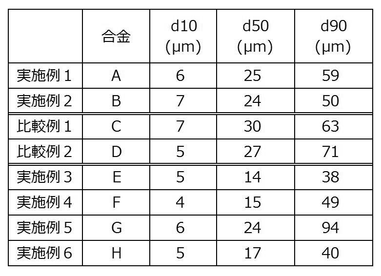
また、合金A及び合金Cの各合金組成を有するFe基アモルファス合金粉末について、それぞれ、Fe基アモルファス合金粉末(粉末粒径:約20μm)の断面(内部)を、透過型電子顕微鏡によって観察し、透過型電子顕微鏡観察画像(TEM像)を得た。
図1Aは、合金Aの合金組成を有するFe基アモルファス合金粉末の断面の透過型電子顕微鏡観察画像(TEM像)(実施例1)であり、図1Bは、図1Aに示すTEM像を説明するための図である。図1Bにおいて、「保護膜」とは、TEM観察用の保護膜を意味し、「粉表面」とは、合金粉末を構成する合金粒子の表面を意味する。
図2Aは、合金Cの合金組成を有するFe基アモルファス合金粉末(比較例1)の断面のTEM像であり、図2Bは、図2Aに示すTEM像を説明するための図である。図2Bにおいて、「析出粒(初期微結晶)」とは、合金溶湯の粒子を急冷凝固させる段階で生じたと考えられるナノ結晶粒を意味する。
図2Aは、合金Cの合金組成を有するFe基アモルファス合金粉末(比較例1)の断面のTEM像であり、図2Bは、図2Aに示すTEM像を説明するための図である。図2Bにおいて、「析出粒(初期微結晶)」とは、合金溶湯の粒子を急冷凝固させる段階で生じたと考えられるナノ結晶粒を意味する。
図1A及び図1Bに示すように、Moを2.97原子%含む、合金Aで表される合金組成を有するアモルファス合金粉末の内部には、微細な結晶粒は観察されず、この合金粉末の合金組織が、アモルファス相からなる合金組織であることが分かる。
一方、図2A及び図2Bに示すように、Moを含まずにNbを2.97原子%含む、合金Cで表される合金組成を有するアモルファス合金粉末の内部には、微細な結晶粒が観察された。
一方、図2A及び図2Bに示すように、Moを含まずにNbを2.97原子%含む、合金Cで表される合金組成を有するアモルファス合金粉末の内部には、微細な結晶粒が観察された。
<Fe基ナノ結晶合金粉末の作製>
上記Fe基アモルファス合金粉末のそれぞれを、目開き25μmの篩を用いて分級し、上記篩を通過した合金粉末を得た。
上記篩を通過した合金粉末の各々に対し、以下の熱処理条件による熱処理を施すことにより、Fe基ナノ結晶合金粉末を得た。
熱処理条件は、まず、480℃まで昇温速度500℃/時間にて昇温し、次に、480から540℃(保持温度)まで昇温速度100℃/時間にて昇温し、次に、540℃(保持温度)で30分保持し、次に、室温まで約1時間で降温する条件とした。
上記Fe基アモルファス合金粉末のそれぞれを、目開き25μmの篩を用いて分級し、上記篩を通過した合金粉末を得た。
上記篩を通過した合金粉末の各々に対し、以下の熱処理条件による熱処理を施すことにより、Fe基ナノ結晶合金粉末を得た。
熱処理条件は、まず、480℃まで昇温速度500℃/時間にて昇温し、次に、480から540℃(保持温度)まで昇温速度100℃/時間にて昇温し、次に、540℃(保持温度)で30分保持し、次に、室温まで約1時間で降温する条件とした。
なお、DSC測定によって求めた各合金組成のTx1及びTx2は、それぞれ、以下の通りであった。
・合金A:Tx1=522℃、Tx2=645℃
・合金B:Tx1=495℃、Tx2=552℃
・合金C:Tx1=530℃、Tx2=650℃
・合金D:Tx1=505℃、Tx2=560℃
・合金E:Tx1=533℃、Tx2=652℃
・合金F:Tx1=512℃、Tx2=648℃
・合金G:Tx1=527℃、Tx2=672℃
・合金H:Tx1=533℃、Tx2=673℃
これらのTx1及びTx2からみて、上記熱処理条件における保持温度540℃は、いずれの合金組成においても、Tx1以上Tx2未満となっていることがわかる。
・合金A:Tx1=522℃、Tx2=645℃
・合金B:Tx1=495℃、Tx2=552℃
・合金C:Tx1=530℃、Tx2=650℃
・合金D:Tx1=505℃、Tx2=560℃
・合金E:Tx1=533℃、Tx2=652℃
・合金F:Tx1=512℃、Tx2=648℃
・合金G:Tx1=527℃、Tx2=672℃
・合金H:Tx1=533℃、Tx2=673℃
これらのTx1及びTx2からみて、上記熱処理条件における保持温度540℃は、いずれの合金組成においても、Tx1以上Tx2未満となっていることがわかる。
<Fe基ナノ結晶合金粉末のTEM観察>
各Fe基ナノ結晶合金粉末について、それぞれ、Fe基ナノ結晶合金粉末(粉末粒径:約20μm)の断面(内部)を、透過型電子顕微鏡によって観察し、透過型電子顕微鏡観察画像(TEM像)を得た。
各Fe基ナノ結晶合金粉末について、それぞれ、Fe基ナノ結晶合金粉末(粉末粒径:約20μm)の断面(内部)を、透過型電子顕微鏡によって観察し、透過型電子顕微鏡観察画像(TEM像)を得た。
図3Aは、合金Aの合金組成を有するFe基ナノ結晶合金粉末(実施例1)の断面のTEM像であり、図3Bは、図3Aに示すTEM像を説明するための図である。
図4Aは、合金Cの合金組成を有するFe基ナノ結晶合金粉末(比較例1)の断面のTEM像であり、図4Bは、図4Aに示すTEM像を説明するための図である。
図3A、図3B、図4A、及び図4Bより、実施例1及び比較例1とも、合金組織中にナノ結晶粒が含まれるが、実施例1におけるナノ結晶粒は、比較例1におけるナノ結晶粒よりも明らかに小さいことがわかる。
図4Aは、合金Cの合金組成を有するFe基ナノ結晶合金粉末(比較例1)の断面のTEM像であり、図4Bは、図4Aに示すTEM像を説明するための図である。
図3A、図3B、図4A、及び図4Bより、実施例1及び比較例1とも、合金組織中にナノ結晶粒が含まれるが、実施例1におけるナノ結晶粒は、比較例1におけるナノ結晶粒よりも明らかに小さいことがわかる。
<Fe基ナノ結晶合金粉末のナノ結晶粒径Dの測定>
各Fe基ナノ結晶合金粉末について、前述した方法により、ナノ結晶粒径Dを測定した。
結果を表3に示す。
各Fe基ナノ結晶合金粉末について、前述した方法により、ナノ結晶粒径Dを測定した。
結果を表3に示す。
ナノ結晶粒径Dを測定するためのX線回折測定における装置及び測定条件は、以下のとおりとした。
(装置)
株式会社リガク製RINT2500PC
(測定条件)
X線源:CoKα(波長λ=0.1789nm)
走査軸:2θ/θ
サンプリング幅:0.020°
スキャンスピ-ド:2.0°/分
発散スリット:1/2°
発散縦スリット:5mm
散乱スリット:1/2°
受光スリット:0.3mm
電圧:40kV
電流:200mA
(装置)
株式会社リガク製RINT2500PC
(測定条件)
X線源:CoKα(波長λ=0.1789nm)
走査軸:2θ/θ
サンプリング幅:0.020°
スキャンスピ-ド:2.0°/分
発散スリット:1/2°
発散縦スリット:5mm
散乱スリット:1/2°
受光スリット:0.3mm
電圧:40kV
電流:200mA
<Fe基ナノ結晶合金粉末の保磁力Hc測定>
各Fe基ナノ結晶合金粉末について、前述した方法により、保磁力Hcを測定した。
結果を表3に示す。
保磁力Hcを求めるための最大磁場が800A/mである条件のB-H曲線は、VSC(Vibrating Sample Magnetometer)によって測定した。
各Fe基ナノ結晶合金粉末について、前述した方法により、保磁力Hcを測定した。
結果を表3に示す。
保磁力Hcを求めるための最大磁場が800A/mである条件のB-H曲線は、VSC(Vibrating Sample Magnetometer)によって測定した。
<磁心の作製及びコアロスPの測定>
各Fe基ナノ結晶合金粉末100質量部に、バインダーとしてのシリコーン樹脂5質量部を加えて混練した。得られた混練物を1トン/cm2のプレス圧力にて成形し、外径13.5mm×内径7.7mm×高さ2.5mmのリング形状の磁心(即ち、トロイダルコア)を得た。
得られた磁心に対し、一次側巻線と二次側巻線とをそれぞれ18ターン巻回した。この状態で、岩通計測株式会社製B-HアナライザSY-8218により、周波数2MHz及び磁場強度30mTの条件で、磁心のコアロスP(kW/m3)を室温で測定した。
結果を表3に示す。
各Fe基ナノ結晶合金粉末100質量部に、バインダーとしてのシリコーン樹脂5質量部を加えて混練した。得られた混練物を1トン/cm2のプレス圧力にて成形し、外径13.5mm×内径7.7mm×高さ2.5mmのリング形状の磁心(即ち、トロイダルコア)を得た。
得られた磁心に対し、一次側巻線と二次側巻線とをそれぞれ18ターン巻回した。この状態で、岩通計測株式会社製B-HアナライザSY-8218により、周波数2MHz及び磁場強度30mTの条件で、磁心のコアロスP(kW/m3)を室温で測定した。
結果を表3に示す。

表3に示すように、本開示における合金組成(合金A、B、及びE~H)を有する実施例1~6のFe基ナノ結晶合金粉末は、本開示における合金組成以外の合金組成(合金C及びD)を有する比較例1及び2のFe基ナノ結晶合金粉末と比較して、ナノ結晶粒径Dが小さく、かつ、保磁力Hcが小さかった。
比較例1及び2におけるナノ結晶粒径Dが大きかった理由は、比較例1及び2では、熱処理前のFe基アモルファス合金粉末の合金組織中に既にナノ結晶粒が存在しており(例えば、比較例1について、図2A及び図2B参照)、これらの結晶粒が、熱処理によって成長したためと考えられる。
これに対し、実施例1~6では、熱処理前のFe基アモルファス合金粉末の合金組織中に結晶粒が存在しておらず、合金組織がアモルファス相からなる合金組織であった(例えば、実施例1について、図1A及び図1B参照)。その結果、実施例1~6では、熱処理により、ナノ結晶粒が小さい(即ち、ナノ結晶粒径Dが小さい)合金組織を有するFe基ナノ結晶合金が得られたと考えられる。
これに対し、実施例1~6では、熱処理前のFe基アモルファス合金粉末の合金組織中に結晶粒が存在しておらず、合金組織がアモルファス相からなる合金組織であった(例えば、実施例1について、図1A及び図1B参照)。その結果、実施例1~6では、熱処理により、ナノ結晶粒が小さい(即ち、ナノ結晶粒径Dが小さい)合金組織を有するFe基ナノ結晶合金が得られたと考えられる。
また、表3に示すように、本開示における合金組成(合金A、B、及びE~H)を有する実施例1~6の磁心は、本開示における合金組成以外の合金組成(合金C及びD)を有する比較例1及び2の磁心と比較して、周波数2MHz及び磁場強度30mTの条件でのコアロスPが低減されていた。
実施例1~6の中でも、Mo及びNbを両方含む合金組成(合金E~H)を有する実施例3~6の磁心は、Moを含みNbを含まない合金組成(合金A及びB)を有する実施例1及び2の磁心と比較して、周波数2MHz及び磁場強度30mTの条件でのコアロスPがより低減されていた。
実施例1~6の中でも、Mo及びNbを両方含む合金組成(合金E~H)を有する実施例3~6の磁心は、Moを含みNbを含まない合金組成(合金A及びB)を有する実施例1及び2の磁心と比較して、周波数2MHz及び磁場強度30mTの条件でのコアロスPがより低減されていた。
次に、実施例3~6の磁心について、コアロスPの測定条件を、周波数3MHz及び磁場強度20mTの条件に変更してコアロスPを測定した。
その結果、周波数3MHz及び磁場強度20mTの条件でのコアロスPは、それぞれ、2017kW/m3(実施例3)、3056kW/m3(実施例4)、2994kW/m3(実施例5)、2876kW/m3(実施例6)であった。
その結果、周波数3MHz及び磁場強度20mTの条件でのコアロスPは、それぞれ、2017kW/m3(実施例3)、3056kW/m3(実施例4)、2994kW/m3(実施例5)、2876kW/m3(実施例6)であった。
2017年8月7日に出願された日本国特許出願2017-152108号の開示は、その全体が参照により本明細書に取り込まれる。
本明細書に記載された全ての文献、特許出願、及び技術規格は、個々の文献、特許出願、及び技術規格が参照により取り込まれることが具体的かつ個々に記された場合と同程度に、本明細書に参照により取り込まれる。
本明細書に記載された全ての文献、特許出願、及び技術規格は、個々の文献、特許出願、及び技術規格が参照により取り込まれることが具体的かつ個々に記された場合と同程度に、本明細書に参照により取り込まれる。
Claims (8)
- 下記組成式(1)で表される合金組成を有し、
ナノ結晶粒を含む合金組織を有するFe基ナノ結晶合金粉末。
Fe100-a-b-c-d-e-f-gCuaSibBcModCreCfNbg … 組成式(1)
組成式(1)中、100-a-b-c-d-e-f-g、a、b、c、d、e、f、及びgは、それぞれ、各元素の原子%を示し、かつ、a、b、c、d、e、f、及びgが、0.10≦a≦1.10、13.00≦b≦16.00、7.00≦c≦12.00、0.50≦d≦5.00、0.001≦e≦1.50、0.05≦f≦0.40、及び、0≦(g/(d+g))≦0.50を満足する。 - 前記組成式(1)において、d及びgが、0<(g/(d+g))≦0.50を満足する請求項1に記載のFe基ナノ結晶合金粉末。
- Fe基ナノ結晶合金粉末の粉末X線回折パターンにおける回折面(110)のピークに基づき、Scherrerの式によって求められるナノ結晶粒径Dが、10nm~40nmである請求項1又は請求項2に記載のFe基ナノ結晶合金粉末。
- 最大磁場が800A/mである条件のB-H曲線から求めた保磁力Hcが、150A/m以下である請求項1~請求項3のいずれか1項に記載のFe基ナノ結晶合金粉末。
- 請求項1~請求項4のいずれか1項に記載のFe基ナノ結晶合金粉末を製造する方法であって、
前記組成式(1)で表される合金組成を有するFe基アモルファス合金粉末を準備する工程と、
前記Fe基アモルファス合金粉末を熱処理することにより前記Fe基ナノ結晶合金粉末を得る工程と、
を有するFe基ナノ結晶合金粉末の製造方法。 - 下記組成式(1)で表される合金組成を有するFe基アモルファス合金粉末。
Fe100-a-b-c-d-e-f-gCuaSibBcModCreCfNbg … 組成式(1)
組成式(1)中、100-a-b-c-d-e-f-g、a、b、c、d、e、f、及びgは、それぞれ、各元素の原子%を示し、かつ、a、b、c、d、e、f、及びgが、0.10≦a≦1.10、13.00≦b≦16.00、7.00≦c≦12.00、0.50≦d≦5.00、0.001≦e≦1.50、0.05≦f≦0.40、及び、0≦(g/(d+g))≦0.50を満足する。 - 請求項1~請求項4のいずれか1項に記載のFe基ナノ結晶合金粉末を含む磁心。
- 周波数2MHz及び磁場強度30mTの条件でのコアロスPが、5000kW/m3以下である請求項7に記載の磁心。
Priority Applications (4)
| Application Number | Priority Date | Filing Date | Title |
|---|---|---|---|
| EP18844142.2A EP3666420B1 (en) | 2017-08-07 | 2018-08-06 | Fe-BASED NANOCRYSTALLINE ALLOY POWDER, METHOD FOR PRODUCING THE SAME, Fe-BASED AMORPHOUS ALLOY POWDER, AND MAGNETIC CORE |
| JP2018557145A JP6493639B1 (ja) | 2017-08-07 | 2018-08-06 | Fe基ナノ結晶合金粉末及びその製造方法、Fe基アモルファス合金粉末、並びに、磁心 |
| CN201880051170.9A CN111093860B (zh) | 2017-08-07 | 2018-08-06 | Fe基纳米晶合金粉末及其制造方法、Fe基非晶合金粉末及磁芯 |
| US16/636,701 US11170920B2 (en) | 2017-08-07 | 2018-08-06 | Fe-based nanocrystalline alloy powder, method of producing the same, Fe-based amorphous alloy powder, and magnetic core |
Applications Claiming Priority (2)
| Application Number | Priority Date | Filing Date | Title |
|---|---|---|---|
| JP2017152108 | 2017-08-07 | ||
| JP2017-152108 | 2017-08-07 |
Publications (1)
| Publication Number | Publication Date |
|---|---|
| WO2019031462A1 true WO2019031462A1 (ja) | 2019-02-14 |
Family
ID=65271682
Family Applications (1)
| Application Number | Title | Priority Date | Filing Date |
|---|---|---|---|
| PCT/JP2018/029474 Ceased WO2019031462A1 (ja) | 2017-08-07 | 2018-08-06 | Fe基ナノ結晶合金粉末及びその製造方法、Fe基アモルファス合金粉末、並びに、磁心 |
Country Status (6)
| Country | Link |
|---|---|
| US (1) | US11170920B2 (ja) |
| EP (1) | EP3666420B1 (ja) |
| JP (1) | JP6493639B1 (ja) |
| CN (1) | CN111093860B (ja) |
| TW (1) | TWI783019B (ja) |
| WO (1) | WO2019031462A1 (ja) |
Cited By (4)
| Publication number | Priority date | Publication date | Assignee | Title |
|---|---|---|---|---|
| JP2021141267A (ja) * | 2020-03-09 | 2021-09-16 | セイコーエプソン株式会社 | 磁性粉末、磁性粉末成形体、および磁性粉末の製造方法 |
| JP2022031111A (ja) * | 2020-08-05 | 2022-02-18 | 日立金属株式会社 | Fe基ナノ結晶合金粉末の製造方法、およびFe基アモルファス合金 |
| JP2022050132A (ja) * | 2020-09-17 | 2022-03-30 | 日本製鉄株式会社 | Fe系合金、Fe系合金薄帯、Fe系非晶質合金及びFe系非晶質合金薄帯 |
| CN117265433A (zh) * | 2023-11-21 | 2023-12-22 | 国网智能电网研究院有限公司 | 一种铁基非晶纳米晶合金及其制备方法 |
Families Citing this family (5)
| Publication number | Priority date | Publication date | Assignee | Title |
|---|---|---|---|---|
| KR102004239B1 (ko) * | 2017-10-20 | 2019-07-26 | 삼성전기주식회사 | 코일 부품 |
| KR102198532B1 (ko) * | 2019-06-25 | 2021-01-06 | 삼성전기주식회사 | 코일 부품 |
| CN111570809A (zh) * | 2020-04-27 | 2020-08-25 | 江苏萌达新材料科技有限公司 | 一种非晶合金粉末及其制备方法 |
| CN114086089B (zh) * | 2020-08-05 | 2025-08-05 | 株式会社博迈立铖 | Fe基纳米晶体合金粉末的制造方法及Fe基非晶合金 |
| CN112435823B (zh) * | 2020-11-09 | 2022-09-02 | 横店集团东磁股份有限公司 | 一种铁基非晶合金粉料及其制备方法和用途 |
Citations (5)
| Publication number | Priority date | Publication date | Assignee | Title |
|---|---|---|---|---|
| JPH044393B2 (ja) | 1986-12-15 | 1992-01-28 | ||
| JP2007182594A (ja) * | 2006-01-04 | 2007-07-19 | Hitachi Metals Ltd | 非晶質合金薄帯、ナノ結晶軟磁性合金ならびにナノ結晶軟磁性合金からなる磁心 |
| JP2014136807A (ja) | 2013-01-15 | 2014-07-28 | Tohoku Techno Arch Co Ltd | 金属粉末の製造装置および金属粉末の製造方法 |
| JP2017095773A (ja) | 2015-11-25 | 2017-06-01 | セイコーエプソン株式会社 | 軟磁性粉末、圧粉磁心、磁性素子および電子機器 |
| JP2017152108A (ja) | 2016-02-22 | 2017-08-31 | 大日本印刷株式会社 | Led素子用基板及びled表示装置 |
Family Cites Families (7)
| Publication number | Priority date | Publication date | Assignee | Title |
|---|---|---|---|---|
| DE112008000720T5 (de) * | 2007-03-20 | 2010-04-29 | Nec Tokin Corp., Sendai | Weichmagnetische Legierung, die weichmagnetische Legierung verwendendes magnetisches Teil und Verfahren zum Herstellen derselbigen |
| KR20110044832A (ko) * | 2008-08-22 | 2011-05-02 | 아키히로 마키노 | 합금 조성물, Fe계 나노 결정 합금 및 그 제조 방법, 및 자성 부품 |
| US9287028B2 (en) * | 2009-08-24 | 2016-03-15 | Nec Tokin Corporation | Alloy composition, Fe-based nano-crystalline alloy and forming method of the same |
| JP5912349B2 (ja) * | 2011-09-02 | 2016-04-27 | Necトーキン株式会社 | 軟磁性合金粉末、ナノ結晶軟磁性合金粉末、その製造方法、および圧粉磁心 |
| DE102012109744B4 (de) * | 2012-10-12 | 2025-10-30 | Vacuumschmelze Gmbh & Co. Kg | Legierung, Magnetkern und Verfahren zum Herstellen eines Bandes aus einer Legierung |
| ES2775211T3 (es) * | 2013-02-15 | 2020-07-24 | Hitachi Metals Ltd | Método de producción de un núcleo magnético anular realizado con aleación magnética blanda, nanocristalina, basada en Fe, y método de producción de un dispositivo magnético que comprende el mismo |
| TWI644330B (zh) * | 2014-03-13 | 2018-12-11 | 日商日立金屬股份有限公司 | 磁心、線圈部件及磁心的製造方法 |
-
2018
- 2018-08-06 WO PCT/JP2018/029474 patent/WO2019031462A1/ja not_active Ceased
- 2018-08-06 US US16/636,701 patent/US11170920B2/en active Active
- 2018-08-06 EP EP18844142.2A patent/EP3666420B1/en active Active
- 2018-08-06 JP JP2018557145A patent/JP6493639B1/ja active Active
- 2018-08-06 CN CN201880051170.9A patent/CN111093860B/zh active Active
- 2018-08-07 TW TW107127351A patent/TWI783019B/zh active
Patent Citations (5)
| Publication number | Priority date | Publication date | Assignee | Title |
|---|---|---|---|---|
| JPH044393B2 (ja) | 1986-12-15 | 1992-01-28 | ||
| JP2007182594A (ja) * | 2006-01-04 | 2007-07-19 | Hitachi Metals Ltd | 非晶質合金薄帯、ナノ結晶軟磁性合金ならびにナノ結晶軟磁性合金からなる磁心 |
| JP2014136807A (ja) | 2013-01-15 | 2014-07-28 | Tohoku Techno Arch Co Ltd | 金属粉末の製造装置および金属粉末の製造方法 |
| JP2017095773A (ja) | 2015-11-25 | 2017-06-01 | セイコーエプソン株式会社 | 軟磁性粉末、圧粉磁心、磁性素子および電子機器 |
| JP2017152108A (ja) | 2016-02-22 | 2017-08-31 | 大日本印刷株式会社 | Led素子用基板及びled表示装置 |
Non-Patent Citations (1)
| Title |
|---|
| See also references of EP3666420A4 |
Cited By (7)
| Publication number | Priority date | Publication date | Assignee | Title |
|---|---|---|---|---|
| JP2021141267A (ja) * | 2020-03-09 | 2021-09-16 | セイコーエプソン株式会社 | 磁性粉末、磁性粉末成形体、および磁性粉末の製造方法 |
| JP2022031111A (ja) * | 2020-08-05 | 2022-02-18 | 日立金属株式会社 | Fe基ナノ結晶合金粉末の製造方法、およびFe基アモルファス合金 |
| JP7695604B2 (ja) | 2020-08-05 | 2025-06-19 | 株式会社プロテリアル | Fe基ナノ結晶合金粉末の製造方法、およびFe基アモルファス合金 |
| JP2022050132A (ja) * | 2020-09-17 | 2022-03-30 | 日本製鉄株式会社 | Fe系合金、Fe系合金薄帯、Fe系非晶質合金及びFe系非晶質合金薄帯 |
| JP7610097B2 (ja) | 2020-09-17 | 2025-01-08 | 日本製鉄株式会社 | Fe系合金薄帯及びFe系非晶質合金薄帯 |
| CN117265433A (zh) * | 2023-11-21 | 2023-12-22 | 国网智能电网研究院有限公司 | 一种铁基非晶纳米晶合金及其制备方法 |
| CN117265433B (zh) * | 2023-11-21 | 2024-02-20 | 国网智能电网研究院有限公司 | 一种铁基非晶纳米晶合金及其制备方法 |
Also Published As
| Publication number | Publication date |
|---|---|
| EP3666420A4 (en) | 2021-02-17 |
| EP3666420A1 (en) | 2020-06-17 |
| CN111093860A (zh) | 2020-05-01 |
| TWI783019B (zh) | 2022-11-11 |
| CN111093860B (zh) | 2022-04-05 |
| EP3666420B1 (en) | 2024-10-09 |
| US20200373045A1 (en) | 2020-11-26 |
| JPWO2019031462A1 (ja) | 2019-11-07 |
| JP6493639B1 (ja) | 2019-04-03 |
| TW201920713A (zh) | 2019-06-01 |
| US11170920B2 (en) | 2021-11-09 |
Similar Documents
| Publication | Publication Date | Title |
|---|---|---|
| JP6493639B1 (ja) | Fe基ナノ結晶合金粉末及びその製造方法、Fe基アモルファス合金粉末、並びに、磁心 | |
| JP6482718B1 (ja) | 軟磁性材料およびその製造方法 | |
| JP6669304B2 (ja) | 結晶質Fe基合金粉末及びその製造方法 | |
| US11817245B2 (en) | Soft magnetic powder | |
| JP6892009B2 (ja) | 合金粉末、Fe基ナノ結晶合金粉末及び磁心 | |
| JP5916983B2 (ja) | 合金組成物、Fe基ナノ結晶合金及びその製造方法、並びに磁性部品 | |
| JP6648856B2 (ja) | Fe基合金、結晶質Fe基合金アトマイズ粉末、及び磁心 | |
| JP2016104900A (ja) | 金属軟磁性合金と磁心、およびその製造方法 | |
| CN111128504A (zh) | 软磁性合金粉末、压粉磁芯、磁性部件及电子设备 | |
| JP2016094651A (ja) | 軟磁性合金および磁性部品 | |
| WO2019208768A1 (ja) | 磁心用粉末、それを用いた磁心及びコイル部品 | |
| JP7148876B2 (ja) | アモルファス合金薄帯、アモルファス合金粉末、及びナノ結晶合金圧粉磁心、並びにナノ結晶合金圧粉磁心の製造方法 | |
| JP7524664B2 (ja) | Fe基合金組成物、Fe基合金組成物の粉末及び磁心 | |
| CN112430791B (zh) | Fe基合金组合物、Fe基合金组合物的粉末和磁芯 | |
| JP7695604B2 (ja) | Fe基ナノ結晶合金粉末の製造方法、およびFe基アモルファス合金 | |
| US20240387083A1 (en) | Fe-based soft magnetic alloy and preparation method therefor | |
| CN114086089A (zh) | Fe基纳米晶体合金粉末的制造方法及Fe基非晶合金 |
Legal Events
| Date | Code | Title | Description |
|---|---|---|---|
| ENP | Entry into the national phase |
Ref document number: 2018557145 Country of ref document: JP Kind code of ref document: A |
|
| 121 | Ep: the epo has been informed by wipo that ep was designated in this application |
Ref document number: 18844142 Country of ref document: EP Kind code of ref document: A1 |
|
| NENP | Non-entry into the national phase |
Ref country code: DE |
|
| ENP | Entry into the national phase |
Ref document number: 2018844142 Country of ref document: EP Effective date: 20200309 |