WO2019031468A1 - 送信装置、送信方法、受信装置、受信方法および撮像装置 - Google Patents
送信装置、送信方法、受信装置、受信方法および撮像装置 Download PDFInfo
- Publication number
- WO2019031468A1 WO2019031468A1 PCT/JP2018/029491 JP2018029491W WO2019031468A1 WO 2019031468 A1 WO2019031468 A1 WO 2019031468A1 JP 2018029491 W JP2018029491 W JP 2018029491W WO 2019031468 A1 WO2019031468 A1 WO 2019031468A1
- Authority
- WO
- WIPO (PCT)
- Prior art keywords
- image
- viewing angle
- wide viewing
- ultra
- imager
- Prior art date
- Legal status (The legal status is an assumption and is not a legal conclusion. Google has not performed a legal analysis and makes no representation as to the accuracy of the status listed.)
- Ceased
Links
Images











Classifications
-
- G—PHYSICS
- G03—PHOTOGRAPHY; CINEMATOGRAPHY; ANALOGOUS TECHNIQUES USING WAVES OTHER THAN OPTICAL WAVES; ELECTROGRAPHY; HOLOGRAPHY
- G03B—APPARATUS OR ARRANGEMENTS FOR TAKING PHOTOGRAPHS OR FOR PROJECTING OR VIEWING THEM; APPARATUS OR ARRANGEMENTS EMPLOYING ANALOGOUS TECHNIQUES USING WAVES OTHER THAN OPTICAL WAVES; ACCESSORIES THEREFOR
- G03B15/00—Special procedures for taking photographs; Apparatus therefor
-
- H—ELECTRICITY
- H04—ELECTRIC COMMUNICATION TECHNIQUE
- H04N—PICTORIAL COMMUNICATION, e.g. TELEVISION
- H04N23/00—Cameras or camera modules comprising electronic image sensors; Control thereof
- H04N23/60—Control of cameras or camera modules
- H04N23/698—Control of cameras or camera modules for achieving an enlarged field of view, e.g. panoramic image capture
-
- G—PHYSICS
- G02—OPTICS
- G02B—OPTICAL ELEMENTS, SYSTEMS OR APPARATUS
- G02B13/00—Optical objectives specially designed for the purposes specified below
- G02B13/06—Panoramic objectives; So-called "sky lenses" including panoramic objectives having reflecting surfaces
-
- G—PHYSICS
- G03—PHOTOGRAPHY; CINEMATOGRAPHY; ANALOGOUS TECHNIQUES USING WAVES OTHER THAN OPTICAL WAVES; ELECTROGRAPHY; HOLOGRAPHY
- G03B—APPARATUS OR ARRANGEMENTS FOR TAKING PHOTOGRAPHS OR FOR PROJECTING OR VIEWING THEM; APPARATUS OR ARRANGEMENTS EMPLOYING ANALOGOUS TECHNIQUES USING WAVES OTHER THAN OPTICAL WAVES; ACCESSORIES THEREFOR
- G03B19/00—Cameras
- G03B19/02—Still-picture cameras
- G03B19/04—Roll-film cameras
- G03B19/07—Roll-film cameras having more than one objective
-
- G—PHYSICS
- G03—PHOTOGRAPHY; CINEMATOGRAPHY; ANALOGOUS TECHNIQUES USING WAVES OTHER THAN OPTICAL WAVES; ELECTROGRAPHY; HOLOGRAPHY
- G03B—APPARATUS OR ARRANGEMENTS FOR TAKING PHOTOGRAPHS OR FOR PROJECTING OR VIEWING THEM; APPARATUS OR ARRANGEMENTS EMPLOYING ANALOGOUS TECHNIQUES USING WAVES OTHER THAN OPTICAL WAVES; ACCESSORIES THEREFOR
- G03B37/00—Panoramic or wide-screen photography; Photographing extended surfaces, e.g. for surveying; Photographing internal surfaces, e.g. of pipe
- G03B37/04—Panoramic or wide-screen photography; Photographing extended surfaces, e.g. for surveying; Photographing internal surfaces, e.g. of pipe with cameras or projectors providing touching or overlapping fields of view
-
- H—ELECTRICITY
- H04—ELECTRIC COMMUNICATION TECHNIQUE
- H04N—PICTORIAL COMMUNICATION, e.g. TELEVISION
- H04N23/00—Cameras or camera modules comprising electronic image sensors; Control thereof
- H04N23/45—Cameras or camera modules comprising electronic image sensors; Control thereof for generating image signals from two or more image sensors being of different type or operating in different modes, e.g. with a CMOS sensor for moving images in combination with a charge-coupled device [CCD] for still images
-
- H—ELECTRICITY
- H04—ELECTRIC COMMUNICATION TECHNIQUE
- H04N—PICTORIAL COMMUNICATION, e.g. TELEVISION
- H04N23/00—Cameras or camera modules comprising electronic image sensors; Control thereof
- H04N23/50—Constructional details
-
- H—ELECTRICITY
- H04—ELECTRIC COMMUNICATION TECHNIQUE
- H04N—PICTORIAL COMMUNICATION, e.g. TELEVISION
- H04N23/00—Cameras or camera modules comprising electronic image sensors; Control thereof
- H04N23/50—Constructional details
- H04N23/55—Optical parts specially adapted for electronic image sensors; Mounting thereof
-
- H—ELECTRICITY
- H04—ELECTRIC COMMUNICATION TECHNIQUE
- H04N—PICTORIAL COMMUNICATION, e.g. TELEVISION
- H04N23/00—Cameras or camera modules comprising electronic image sensors; Control thereof
- H04N23/90—Arrangement of cameras or camera modules, e.g. multiple cameras in TV studios or sports stadiums
-
- H—ELECTRICITY
- H04—ELECTRIC COMMUNICATION TECHNIQUE
- H04N—PICTORIAL COMMUNICATION, e.g. TELEVISION
- H04N5/00—Details of television systems
- H04N5/222—Studio circuitry; Studio devices; Studio equipment
- H04N5/262—Studio circuits, e.g. for mixing, switching-over, change of character of image, other special effects ; Cameras specially adapted for the electronic generation of special effects
- H04N5/265—Mixing
Definitions
- the present technology relates to a transmission device, a transmission method, a reception device, a reception method, and an imaging device, and more particularly, to a transmission device that handles a super-viewing angle image for obtaining an omnidirectional image.
- an imaging device performs imaging in a back-to-back method to obtain front and back images of an ultra-wide viewing angle having a viewing angle of 180 ° or more. Creating an equidistant cylindrical image from one image and transmitting it to the communication terminal, and the communications terminal generates an omnidirectional image based on the equidistant cylindrical image, and from the omnidirectional image according to the user's gaze direction It is described that the captured image is cut out to obtain a display image.
- the imaging device creates an equidistant cylindrical image from the front and back images of the ultra-wide viewing angle and transmits it to the communication terminal. It is configured to create an astronomical image. Since the correct-distance cylindrical image intervenes, the processing load on the imaging apparatus is heavy, and image quality deterioration occurs, making it difficult to realize high-quality real-time delivery.
- An object of the present technology is to enable high-quality real-time delivery of an omnidirectional image.
- An imaging unit for obtaining a front image and a rear image of an ultra-wide viewing angle having a viewing angle of 180 ° or more;
- a transmitter comprising: a transmitter configured to transmit the front image and the rear image of the ultra-wide viewing angle to an external device.
- the imaging unit obtains a front image and a rear image of an ultra-wide viewing angle having a viewing angle of 180 ° or more.
- the imaging unit captures a front image captured by a fisheye lens to obtain a front image of an ultra-wide viewing angle, and a rear image captured by a fisheye lens to capture an image at an ultra-wide viewing angle. It may be adapted to have a second imager to obtain a back surface image.
- the second imager is arranged rotated by 90 ° with respect to the first imager, and the first imager is a part of the front side image captured by the fisheye lens on the upper end side and the lower end side
- the second imager may be configured to capture an image on the rear surface side captured by a fisheye lens with a portion on the left end side and the right end side missing.
- each imager can capture an image captured by the fisheye lens in a larger size, and image quality can be improved.
- image part which is missing in each imager is captured by the other imager, it does not become an obstacle for obtaining the omnidirectional image on the receiving side.
- a front image and a rear image obtained by two imagers are combined in the same positional relationship as the two front leathers of a baseball to create a full spherical image.
- the viewing angle up to the coupling boundary in the left and right direction on the front side is considerably wide, it is difficult for the user to feel discomfort in the image when the user gazes the viewing direction to the left and right.
- the transmitter transmits a front image and a rear image of an ultra-wide viewing angle to an external device.
- the transmitting unit may further transmit lens information for pasting the two images on the inner surface of the sphere and obtaining a full spherical image, together with an ultra-wide viewing angle front and back images. Good.
- the lens information By transmitting the lens information in this manner, on the reception side, it is possible to easily and appropriately create the omnidirectional image from the front image and the rear image of the ultra-wide viewing angle based on the lens information.
- the transmitting unit may be configured to combine and transmit the front image and the back image of the ultra-wide viewing angle. By combining and transmitting the two images in this manner, it is possible to guarantee the synchronization relationship between the two images.
- the front image and the back image of the ultra-wide viewing angle obtained by the imaging unit are transmitted to the external device. Therefore, it does not convert the front and back images of ultra-wide viewing angle into a correct-distance cylindrical image and transmit it, there is no processing load due to this conversion, and there is no deterioration in image quality due to this conversion. Image quality real-time delivery becomes possible.
- the other concept of this technology has a receiver that receives front and back images of an ultra-wide viewing angle with a viewing angle of 180 ° or more from an external device,
- the front image of the super-wide viewing angle is obtained by imaging the front side image captured by the fisheye lens in a state in which a part of the upper end side and the lower end side is lacking.
- the front image of the super-wide viewing angle is obtained by imaging the image on the rear surface side captured by the fisheye lens in a state in which a part on the left end side and the right end side is lacking.
- the reception device further includes an image processing unit that applies the front image and the back image of the ultra-wide viewing angle to the inner surface of the sphere to obtain an omnidirectional image.
- the reception unit receives a front image and a rear image of an ultra-wide viewing angle having a viewing angle of 180 ° or more from an external device.
- the front image of the super-wide viewing angle is obtained by imaging the front side image captured by the fisheye lens in a state in which a part of the upper end side and the lower end side is missing.
- the front image of the ultra-wide viewing angle is obtained by imaging the image on the rear surface side captured by the fisheye lens in a state in which a part on the left end side and the right end side is missing.
- the receiving unit further receives lens information for applying the two images to the inner surface of the sphere and obtaining a full spherical image, together with the front and back images of ultra-wide viewing angle, and the image processing unit
- a front image and a rear image of an ultra-wide viewing angle may be attached to the inner surface of a sphere based on lens information to obtain the above-mentioned omnidirectional image. In this case, it is possible to easily and appropriately create the omnidirectional image from the front and back images of the ultra-wide viewing angle.
- the front image and the back surface image of the ultra-wide viewing angle received from the external device are attached to the inner surface of the sphere to obtain the omnidirectional image. Therefore, it is possible to obtain a high-quality all-sky image, not to create a full-sky image from a regular-range cylindrical image obtained by converting the front image and the back-surface image of an ultra-wide viewing angle.
- a first imager for capturing a front image captured by a fisheye lens to obtain a front image with an ultra-wide viewing angle A second imager for capturing a back side image captured by a fisheye lens to obtain a back side image of an ultra-wide viewing angle;
- the second imager is arranged rotated by 90 ° with respect to the first imager, The first imager captures an image on the front side captured by the fisheye lens, with parts of the upper end side and the lower end side lacking.
- the second imager is an image pickup apparatus which picks up an image on the rear surface side captured by the fisheye lens in a state in which a part on the left end side and the right end side is missing.
- An imaging device includes a first imager and a second imager.
- the first imager captures an image on the front side captured by the fisheye lens to obtain a front image of an ultra-wide viewing angle.
- the second imager captures an image of the rear surface side captured by the fisheye lens to obtain a rear surface image of an ultra-wide viewing angle.
- the second imager is arranged rotated by 90 ° with respect to the first imager.
- the image on the front side captured by the fisheye lens is captured in a state in which a part of the upper end side and the lower end side is missing.
- the image on the rear surface side captured by the fisheye lens is captured in a state in which a part on the left end side and the right end side is missing.
- the second imager is disposed rotated by 90 ° with respect to the first imager. Therefore, in each imager, it is possible to capture an image captured by the fisheye lens with a larger size, and it is possible to improve the image quality. In addition, since the image part missing in each imager is captured by the other imager, it does not become a hindrance for obtaining an omnidirectional image from two images.
- the two images are combined in the same positional relationship as the two front leathers of the baseball to create the omnidirectional image. Therefore, the viewing angle up to the coupling boundary in the left and right direction on the front side is considerably wide, so that it is difficult for the user to feel discomfort in the image when the user gazes the viewing direction to the left and right.
- the effect described here is not necessarily limited, and may be any effect described in the present disclosure.
- FIG. 1 shows a configuration example of a distribution system 10 as an embodiment.
- the distribution system 10 includes a camera 110 and a personal computer 120 which constitute a transmission side device, a cloud server 210, and a head mounted display 310 which constitutes a reception side device.
- the receiving device is the head mounted display 310, but is not limited to this, and may be another device such as a projector, a personal computer, a smartphone, a tablet or the like.
- the camera 110 and the personal computer 120 are connected by a digital interface, in this case, high-definition multimedia interface (HDMI). Further, the personal computer 120 and the cloud server 210 are connected by an internet circuit. Furthermore, the cloud server 210 and the head mounted display 310 are connected by an internet circuit. "HDMI” is a registered trademark.
- the camera 110 constitutes an imaging device.
- the camera 110 captures an object and obtains front and back images of an ultra-wide viewing angle having a viewing angle of 180 ° or more, for example, 220 ° or 250 °.
- the image may be either a moving image or a still image, but here, it is assumed to be a moving image.
- the personal computer 120 transmits the front image and the back image of the ultra-wide viewing angle obtained by the camera 110 to the head mounted display 310 as an external device through the cloud server 210.
- the personal computer 120 transmits the image data to the H.264 system.
- a moving picture stream obtained by coding in a moving picture compression format such as H.264 / AVC is placed on a container such as MPEG2-TS and transmitted as IP streaming data.
- the personal computer 120 transmits a moving image stream, and further transmits lens information for attaching a front image and a rear surface image of an ultra-wide viewing angle to the inner surface of a sphere to obtain an omnidirectional image.
- the lens information By transmitting the lens information in this manner, the head mounted display 310 can easily and appropriately create the omnidirectional image from the front image and the back image of the ultra-wide viewing angle based on the lens information. .
- the lens information is given to the personal computer 120 by the operation of the transmitting user.
- the lens information may be manually input by the user from the keyboard, or may be supplied from a storage medium such as a USB memory. The details of the lens information will be described later. It is not always necessary to transmit the lens information together with the moving picture stream, and the head mount display 310 may be supplied and used by another means.
- the cloud server 210 includes a reception server 211 and a distribution server 212.
- the receiving server 211 receives the IP streaming data transmitted from the personal computer 120.
- the distribution server 212 transmits (distributes) the IP streaming data received by the reception server 211 to the head mounted display 310.
- the head mounted display 310 receives IP streaming data from the distribution server 212, takes out a front image and a rear surface image of an ultra-wide viewing angle, and pastes these images on the inner surface of a sphere based on lens information Create Then, the head mounted display 310 extracts an image of a region according to the gaze direction of the user from the omnidirectional image and displays it on the display. Even when the receiving device is not the head mounted display 310, a omnidirectional image is created in the same manner, and image display using this omnidirectional image is performed.
- the horizontal and vertical positional relationship between the imager forming the imaging unit of the front image and the imager forming the imaging unit of the rear image is the same.
- both imagers are arranged so that the horizontal direction coincides with the horizontal direction of the camera 110 and the vertical direction coincides with the vertical direction of the camera 110.
- the entire image captured by the fisheye lens is captured by each imager.
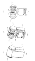
- FIGS. 2A to 2C show configuration examples of the camera 110.
- FIG. FIG. 2A is a perspective view showing the appearance of the camera 110.
- FIG. An imaging unit is disposed above the housing 111, and a fisheye lens 112f constituting an imaging unit of a front image and a fisheye lens 112b constituting an imaging unit of a rear image are present.
- FIG. 2B is a perspective view of a state in which a part of the housing 111 is removed. Moreover, FIG.2 (c) has shown the side view in the state which removed the housing
- Inside the camera 110 there are an imager 113f for capturing an image on the front side captured by the fisheye lens 112f, and an imager 113b for capturing an image on the back surface captured by the fisheye lens 112b.
- the horizontal and vertical positional relationship between the imager 113 f and the imager 113 b is the same.
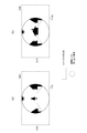
- FIG. 3A shows the positional relationship between the light receiving unit of the imager 113 f that captures an image on the front side and the image captured by the fisheye lens 112 f when imaging is performed at the imaging position illustrated in FIG. 4.
- the image captured by the fisheye lens 112f is entirely contained in the light receiving unit of the imager 113f, and the entire image captured by the fisheye lens 112f is captured by the imager 113f.
- FIG. 3B shows the positional relationship between the light receiving unit of the imager 113b that captures an image on the back side and the image captured by the fisheye lens 112b when imaging is performed at the imaging position illustrated in FIG.
- the image captured by the fisheye lens 112b is entirely contained in the light receiving unit of the imager 113b, and the entire image captured by the fisheye lens 112b is captured by the imager 113b.
- numerical values "3840" and "2160” indicate the resolutions of the imagers 113f and 113b, and indicate that the horizontal resolution is 3840 and the vertical resolution is 2160.
- the resolutions of the imagers 113f and 113b are one example, and the resolutions are not limited to this.
- the front and back images of the ultra-wide viewing angle obtained by being imaged by the imagers 113f and 113b are combined, and the image data of this combined image is sent to the personal computer 120.
- FIGS. 5A and 5B show an example of a front image and a rear image of an ultra-wide viewing angle captured by the imagers 113f and 113b
- FIG. 5C shows an example of a combined image.
- the combined image for example, compression processing is applied to the front image and back surface image of the ultra-wide viewing angle, and these images are arranged side by side in the horizontal direction.
- the horizontal resolution is 4096 and the vertical resolution is 2160.
- the image data of the combined image sent from the camera 110 is encoded to obtain a moving image stream. Then, this moving picture stream is placed on a container such as MPEG2-TS, and transmitted to the cloud server 210 as IP streaming data.
- the personal computer 120 simultaneously transmits the moving image stream and lens information for each of the two imaging units on the front side and the rear side.
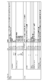
- FIG. 6 shows an example of lens information.
- the lens information includes light receiving unit information such as the resolution of the imager, and information such as the position and size of the image captured by the fisheye lens projected onto the light receiving unit of the imager.
- a front image and a back surface image of an ultra-wide viewing angle are separated from the combined image extracted from the IP streaming data, and these images are attached to the inner surface of the sphere based on lens information An image is created. Then, in the head mounted display 310, an image of a region according to the user's gaze direction is extracted from the omnidirectional image and displayed on the display (display unit).
- FIG. 7A shows an example of the combined image.
- FIGS. 7 (b) and 7 (c) show an example of front and back images of an ultra-wide viewing angle separated from the combined image.
- FIG. 7 (d) shows an example of the omnidirectional image created by attaching the separated front and back images of the ultra-wide viewing angle to the inner surface of the sphere based on the lens information.
- the illustration of the pasted image is omitted for simplification of the drawing. "O" indicates the center of the sphere.
- FIG. 8 shows a configuration example of the camera 110 and the personal computer 120.
- the camera 210 includes a control unit 117, fisheye lenses 112f and 112b, imagers 113f and 113b, imaging signal processing units 114f and 114b, front and rear surface image combining units 115, and an HDMI transmission unit 116.
- the control unit 117 controls the operation of each unit of the camera 110.
- the fisheye lens 112 f and the imager 113 f constitute an imaging unit on the front side.
- the image on the front side captured by the fisheye lens 112f is projected on the light receiving unit of the imager 113f (see FIG. 3A), and the imager 113f captures an imaging signal of the front image with an ultra-wide viewing angle (see FIG. 5A). Is obtained.
- the imaging signal processing unit 114 f performs sample hold and gain control, conversion from analog signals to digital signals, and white balance adjustment for the imaging signal (analog signal) of the front image of the ultra-wide viewing angle obtained by the imager 113 f , Gamma correction, etc., to generate image data of the front image of the ultra-wide viewing angle.
- the fisheye lens 112 b and the imager 113 b constitute an imaging unit on the rear side.
- the image on the rear surface side captured by the fisheye lens 112b is projected on the light receiving unit of the imager 113b (see FIG. 3B), and an imager signal of the rear surface image (see FIG. 5B) with an ultra-wide viewing angle from the imager 113b. Is obtained.
- the imaging signal processing unit 114b performs sample hold and gain control, converts an analog signal to a digital signal, and further adjusts the white balance with respect to the imaging signal (analog signal) of the back surface image of the ultra-wide viewing angle obtained by the imager 113b. , Gamma correction, etc., to generate image data of the back surface image of the ultra-wide viewing angle.
- the front and back image combining unit 115 combines the image data of the front and back images of the ultra-wide viewing angle obtained by the imaging signal processing units 114f and 114b, and generates the image data of the combined image (see FIG. 5C).
- Generate The HDMI transmitting unit 116 transmits the image data of the combined image obtained by the front and back surface image combining unit 115 to the personal computer 120 via the HDMI transmission path by communication conforming to the HDMI.
- the personal computer 120 includes a control unit 121, a user operation unit 122, an HDMI receiving unit 123, an encoding unit 124, and a network transmission unit 125.
- the control unit 121 controls the operation of each unit of the personal computer 120.
- the user operation unit 122 is a keyboard, a mouse, a touch panel, a remote control or the like for the user to perform various operations.
- the HDMI receiving unit 123 receives the image data of the combined image from the camera 110 via the HDMI transmission path by communication conforming to the HDMI.
- the encoding unit 124 transmits the image data of the combined image to H.264.
- the video stream is obtained by encoding in a video compression format such as H.264 / AVC.
- the network transmission unit 125 converts the moving picture stream obtained by the encoding unit 124 into TS packets, further converts them into IP packets, and transmits them as IP streaming data to the cloud server 210 via the Internet. In addition, the network transmission unit 125 transmits lens information (see FIG. 6) given by user operation from the user operation unit 122 together with the moving picture stream.
- FIG. 9 shows a configuration example of the head mounted display 310.
- the head mounted display 310 includes a control unit 311, a user operation unit 312, a network reception unit 313, a decoding unit 314, a front and back image separation unit 315, an image attachment unit 316, and a display image acquisition unit 317. , A display unit 318, and a sensor unit 319.
- the control unit 311 controls the operation of each unit of the head mounted display 310.
- the user operation unit 312 is a key, a button, a touch panel, a remote control, or the like for the user to perform various operations.
- the network reception unit 313 receives IP streaming data and lens information sent from the cloud server 210.
- the network reception unit 313 sends the received lens information to the control unit 311.
- the network reception unit 313 processes the received IP streaming data to obtain a moving image stream including encoded image data of a combined image.
- the decoding unit 314 performs decoding processing on the moving picture stream obtained by the network reception unit 313, and obtains image data of a combined image (see FIG. 7A).
- the front and back surface image separation unit 315 processes the image data of the combined image obtained by the decoding unit 314, and the front image (see FIG. 7 (b)) and the back surface image (see FIG. 7 (c)) with an ultra-wide viewing angle. To obtain the image data of
- the image pasting unit 316 spheres the front and back images of the ultra-wide viewing angle based on the image data of the front and back images of the ultra-wide viewing angle obtained by the front and back image separating unit 315 and the lens information. It pastes (maps) on the inner surface of to create an omnidirectional image (see FIG. 7 (d)).
- the sensor unit 319 detects the gaze direction of the user based on detection outputs of various sensors such as an acceleration / orientation sensor.
- the display image acquisition unit 317 extracts an image of a region corresponding to the user's gaze direction detected by the sensor unit 319 from the omnidirectional image created by the image pasting unit 316 as a display image, and the image data is extracted Output.
- the display unit (display) 318 displays an image based on the image data obtained by the display image obtaining unit 317.
- the camera 110 combines front and back images of an ultra-wide viewing angle obtained by imaging
- the personal computer 120 combines the image data of this combined image through the cloud server 210.
- the head mounted display 310 It is not intended to convert the front and back images of ultra-wide viewing angle into a regular cylindrical image for transmission, there is no processing load due to this conversion, and there is no deterioration in image quality due to this conversion, and high image quality of the omnidirectional image Real-time delivery becomes possible.
- the horizontal and vertical positional relationship between the imager forming the imaging unit of the front image and the imager forming the imaging unit of the rear image is different.
- the imager constituting the imaging unit of the front image is arranged such that the horizontal direction coincides with the horizontal direction of the camera 110 and the vertical direction coincides with the vertical direction of the camera 110.
- the imager constituting the imaging unit of the rear surface image is in a state rotated by 90 ° with respect to the imager constituting the imaging unit of the front image, and the horizontal direction coincides with the vertical direction of the camera 110 and the vertical direction Are arranged to coincide with the horizontal direction of the camera 110.
- an image captured by a fisheye lens is captured in a state lacking a part of the image. That is, in the imager constituting the imaging unit of the front image, the front-side image captured by the fisheye lens is imaged in a state where a part of the upper end side and the lower end side is missing. On the other hand, in the imager constituting the imaging unit of the rear surface image, the image on the rear surface side captured by the fisheye lens is captured in a state in which a part on the left end side and the right end side is missing.
- FIG. 10A is a perspective view showing the appearance of the camera 110.
- FIG. An imaging unit is disposed above the housing 111, and a fisheye lens 112f constituting an imaging unit of a front image and a fisheye lens 112b constituting an imaging unit of a rear image are present.
- FIG. 10B is a perspective view of a state in which a part of the housing 111 is removed. Further, FIG. 10C shows a side view in a state where the front part of the housing 111 is removed.
- Inside the camera 110 there are an imager 113f for capturing an image on the front side captured by the fisheye lens 112f and an imager 113b for capturing an image on the front side captured by the fisheye lens 112f.
- the horizontal and vertical positional relationship between the imager 113 f and the imager 113 b is different. That is, the imager 113b is rotated by 90 ° with respect to the imager 113f.
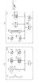
- FIG. 11A shows the positional relationship between the light receiving unit of the imager 113 f that captures an image on the front side and the image captured by the fisheye lens 112 f when imaging is performed at the imaging position illustrated in FIG. 4.
- a part of the upper end side and the lower end side of the image captured by the fisheye lens 112f is out of the light receiving portion of the imager 113f, and an image captured by the fisheye lens 112f in the imager 113f lacks a part of the upper end side and the lower end side. It is imaged.
- FIG. 11B shows the positional relationship between the light receiving unit of the imager 113b that captures an image on the rear side and the image captured by the fisheye lens 112b when imaging is performed at the imaging position illustrated in FIG.
- the left end side and the right end side of the image captured by the fisheye lens 112b are out of the light receiving portion of the imager 113b, and the image captured by the fisheye lens 112b in the imager 113b lacks a part of the left end side and the right edge It is imaged.
- numerical values "3840" and "2160” indicate the resolutions of the imagers 113f and 113b, and indicate that the horizontal resolution is 3840 and the vertical resolution is 2160.
- the resolutions of the imagers 113f and 113b are one example, and the resolutions are not limited to this.
- the front and back images of the ultra-wide viewing angle obtained by imaging with the camera 110 are combined, and the image data of this combined image is encoded to obtain a moving picture stream. Then, this moving picture stream is placed on a container such as MPEG2-TS, and transmitted to the cloud server 210 as IP streaming data.
- a container such as MPEG2-TS
- FIGS. 12 (a) and 12 (b) show an example of the front and back images of the ultra-wide viewing angle captured by the imagers 113f and 113b
- FIG. 12 (c) shows an example of the combined image.
- horizontal front compression processing is applied to the front image and back surface image of the ultra-wide viewing angle, and they are arranged side by side in the horizontal direction.
- the horizontal resolution is 4096 and the vertical resolution is 2160.
- lens information for each of the front and rear imaging units is also transmitted to the cloud server 210.
- the lens information includes light receiving unit information such as the resolution of the imager, and information such as the position and size of an image captured by a fisheye lens projected onto the light receiving unit in the imager.
- head mounted display 310 front and back images of ultra-wide viewing angle are separated from the combined image taken from the IP streaming data, and the back image is subjected to a 90 ° rotation process and then these ultra wide A front image and a rear image of the viewing angle are attached to the inner surface of the sphere in the same positional relationship as the two front leathers of the baseball based on the lens information to create the omnidirectional image. Then, in the head mounted display 310, an image of a region according to the gaze direction of the user is extracted from the omnidirectional image and displayed on the display.
- FIG. 13A shows an example of the combined image.
- FIGS. 13 (b) and 13 (c) show an example of the front and back images of the ultra-wide viewing angle separated from the combined image.
- FIG.13 (d) has shown an example of the back surface image of the super-wide viewing angle after the rotation process of 90 degrees is performed.
- FIG.13 (e) has shown an example of the omnidirectional image created by the front surface image and back surface image of an ultra-wide viewing angle being stuck on the inner surface of a spherical body based on lens information.
- the illustration of the pasted image is omitted for simplification of the drawing.
- two front leather seams of baseball are displayed. "O" indicates the center of the sphere.
- FIG. 14 shows a configuration example of the camera 110 and the personal computer 120.
- the camera 210 includes a control unit 117, fisheye lenses 112f and 112b, imagers 113f and 113b, imaging signal processing units 114ff and 114b, and HDMI transmission units 116f and 116b.
- the control unit 117 controls the operation of each unit of the camera 110.
- the fisheye lens 112 f and the imager 113 f constitute an imaging unit on the front side.
- the front side image captured by the fisheye lens 112f is projected on the light receiving portion of the imager 113f with parts of the upper end side and the lower end side lacking (see FIG. 11A), and from the imager 113f, the upper end side and the lower end side
- An imaging signal of a front image (see FIG. 12 (a)) of an ultra-wide viewing angle in a state in which a part of.
- the imaging signal processing unit 114 f performs sample hold and gain control, conversion from analog signals to digital signals, and white balance adjustment for the imaging signal (analog signal) of the front image of the ultra-wide viewing angle obtained by the imager 113 f , Gamma correction, etc., to generate image data of the front image of the ultra-wide viewing angle.
- the fisheye lens 112 b and the imager 113 b constitute an imaging unit on the front side.
- the front side image captured by the fisheye lens 112b is projected on the light receiving portion of the imager 113b with the left end side and the right end side lacking (see FIG. 11B), and from the imager 113b
- the imaging signal processing unit 114b performs sample hold and gain control, converts an analog signal to a digital signal, and further adjusts the white balance with respect to the imaging signal (analog signal) of the back surface image of the ultra-wide viewing angle obtained by the imager 113b. , Gamma correction, etc., to generate image data of the back surface image of the ultra-wide viewing angle.
- the HDMI transmitting unit 116 f transmits the front image (see FIG. 12A) of the super-wide viewing angle obtained by the imaging signal processing unit 114 f to the personal computer 120 via the HDMI transmission path through communication conforming to HDMI. Send image data. Further, the HDMI transmitting unit 116b transmits the rear surface image of the super-wide viewing angle obtained by the imaging signal processing unit 114b to the personal computer 120 through the HDMI transmission path by communication conforming to HDMI (see FIG. 12B). Send the image data of).
- the personal computer 120 includes a control unit 121, a user operation unit 122, HDMI receiving units 123f and 123b, a front and back image combining unit 126, an encoding unit 124, and a network transmission unit 125.
- the control unit 121 controls the operation of each unit of the personal computer 120.
- the user operation unit 122 is a keyboard, a mouse, a touch panel, a remote control or the like for the user to perform various operations.
- the HDMI receiving unit 123f receives the image data of the front image (see FIG. 12A) of the ultra-wide viewing angle from the camera 110 via the HDMI transmission path by the communication based on the HDMI. Also, the HDMI receiving unit 123b receives the image data of the back surface image (see FIG. 12B) of the ultra-wide viewing angle from the camera 110 via the HDMI transmission path by the communication based on the HDMI.
- the front and back image combining unit 115 combines the image data of the front image and the back image of the ultra-wide viewing angle received by the HDMI receiving units 123f and 123b, and generates the image data of the combined image (see FIG. 12C).
- Generate The encoding unit 124 transmits the image data of the combined image to H.264.
- the video stream is obtained by encoding in a video compression format such as H.264 / AVC.
- the network transmission unit 125 converts the moving picture stream obtained by the encoding unit 124 into TS packets, further converts them into IP packets, and transmits them as IP streaming data to the cloud server 210 via the Internet. In addition, the network transmission unit 125 transmits lens information (see FIG. 6) given by user operation from the user operation unit 122 together with the moving picture stream.
- FIG. 15 shows a configuration example of the head mounted display 310.
- the head mounted display 310 includes a control unit 311, a user operation unit 312, a network reception unit 313, a decoding unit 314, front and rear image separation units 315, a rear image rotation unit 320, and an image attachment unit 316. , A display image acquisition unit 317, a display unit 318, and a sensor unit 319.
- the control unit 311 controls the operation of each unit of the head mounted display 310.
- the user operation unit 312 is a key, a button, a touch panel, a remote control, or the like for the user to perform various operations.
- the network reception unit 313 receives IP streaming data and lens information sent from the cloud server 210.
- the network reception unit 313 sends the received lens information to the control unit 311.
- the network reception unit 313 processes the received IP streaming data to obtain a moving image stream including encoded image data of a combined image.
- the decoding unit 314 performs decoding processing on the moving picture stream obtained by the network reception unit 313 to obtain image data of a combined image (see FIG. 13A).
- the front and back surface image separation unit 315 processes the image data of the combined image obtained by the decoding unit 314, and the front image (see FIG. 13 (b)) and the back surface image (see FIG. 13 (c)) with an ultra-wide viewing angle. To obtain the image data of
- the rear surface image rotation unit 320 performs processing of rotating the image data of the rear surface image of the ultra-wide viewing angle obtained by the front and rear surface image separation unit 315 by 90 °, and returns the horizontal and vertical relationships to their original positions.
- the image data of the back surface image (refer FIG.13 (d)) of a super-wide viewing angle is acquired.
- the image pasting unit 316 includes image data and lens information of the front image of the ultra-wide viewing angle obtained by the front and back image separating unit 315 and the back-surface image of the ultra-wide viewing angle rotated by the rear image rotating unit 320. Based on this, the front and back images of ultra-wide viewing angles are pasted (mapped) on the inner surface of the sphere to create a full spherical image (see FIG. 13E).
- a front image and a rear image of an ultra-wide viewing angle are attached to the inner surface of the sphere in the same positional relationship as the two front leathers of a baseball to create a omnidirectional image.
- the viewing angle up to the coupling boundary in the left and right direction on the front side is considerably wide, it is difficult for the user to feel discomfort in the image when the user gazes the viewing direction to the left and right.
- the imaging direction is set so that the combined boundary does not overlap with the main subject direction such as the stage direction.
- the sensor unit 319 detects the gaze direction of the user based on detection outputs of various sensors such as an acceleration / orientation sensor.
- the display image acquisition unit 317 extracts an image of a region corresponding to the user's gaze direction detected by the sensor unit 319 from the omnidirectional image created by the image pasting unit 316 as a display image, and the image data is extracted Output.
- the display unit (display) 318 displays an image based on the image data obtained by the display image obtaining unit 317.
- the front image and the back image of the ultra-wide viewing angle obtained by the camera 110 are combined by the personal computer 120, and the image data of this combined image is transmitted through the cloud server 210 to the head mounted display 310.
- the personal computer 120 does not convert the front and back images of ultra-wide viewing angle into a correct-distance cylindrical image and transmit it, there is no processing load due to this conversion, and there is no deterioration in image quality due to this conversion. Image quality real-time delivery becomes possible.
- the imager 113b constituting the image pickup section for the rear surface image is arranged rotated by 90 ° with respect to the imager 113f constituting the image pickup section for the front image, and the imager 113f is a fisheye lens 112f.
- the image taken on the front side is taken with the upper end and the lower end partially devoid, and the imager 113b is the image taken with the fisheye lens 112b, the left end and the right end partially devoid To capture images.
- each imager it is possible to capture an image captured by the fisheye lens in a larger size, and image quality can be improved.
- the image part missing in each imager is captured by the other imager, it does not become an obstacle for obtaining the omnidirectional image in the head mounted display 310.
- the head mounted display 310 combines the front image and the back image obtained by the two imagers in the same positional relationship as the two front leathers of a baseball to create an omnidirectional image. Do. Therefore, the viewing angle up to the coupling boundary in the left and right direction on the front side is considerably wide, so that it is difficult for the user to feel discomfort in the image when the user gazes the viewing direction to the left and right.
- the horizontal and vertical positional relationships between the imager forming the imaging unit of the front image and the imager forming the imaging unit of the rear image are different.
- the imager constituting the imaging unit of the front image is arranged such that the horizontal direction coincides with the horizontal direction of the camera 110 and the vertical direction coincides with the vertical direction of the camera 110.
- the imager constituting the imaging unit of the rear surface image is in a state rotated by 90 ° with respect to the imager constituting the imaging unit of the front image, and the horizontal direction coincides with the vertical direction of the camera 110 and the vertical direction Are arranged to coincide with the horizontal direction of the camera 110.
- an image captured by a fisheye lens is captured in a state lacking a part of the image. That is, in the imager constituting the imaging unit of the front image, the front-side image captured by the fisheye lens is imaged in a state where a part of the upper end side and the lower end side is missing. On the other hand, in the imager constituting the imaging unit of the rear surface image, the image on the rear surface side captured by the fisheye lens is captured in a state in which a part on the left end side and the right end side is missing.
- the image data of the front image and the back image of the ultra-wide viewing angle obtained by imaging with the camera 110 are respectively encoded to obtain a moving picture stream. Then, each moving picture stream is placed on a container such as MPEG2-TS, and transmitted to the cloud server 210 as IP streaming data.
- lens information (see FIG. 6) for each of the two imaging units on the front side and the rear side is also transmitted to the cloud server 210 together with each moving picture stream.
- the lens information includes light receiving unit information such as the resolution of the imager, and information such as the position and size of an image captured by a fisheye lens projected onto the light receiving unit in the imager.
- front and back images of ultra-wide viewing angle are taken out of the IP streaming data, and 90 ° rotation processing is performed on the back surface image, and then these front and back images of super-wide viewing angle
- a rear surface image is pasted on the inner surface of a sphere in the same positional relationship as the two front leathers of a baseball based on lens information, and an omnidirectional image is created.
- an image of a region according to the gaze direction of the user is extracted from the omnidirectional image and displayed on the display.
- FIG. 16 (a) shows an example of a front image of an ultra-wide viewing angle.
- FIG. 16 (b) shows an example of the back surface image of the ultra-wide viewing angle.
- FIG. 16C shows an example of the rear surface image of the ultra-wide viewing angle after being subjected to the 90 ° rotation processing.
- FIG. 16D shows an example of a omnidirectional image created by attaching a front image and a rear image of an ultra-wide viewing angle to the inner surface of a sphere based on lens information. The illustration of the pasted image is omitted for simplification of the drawing.
- two front leather seams of baseball are displayed. "O" indicates the center of the sphere.
- FIG. 17 shows a configuration example of the camera 110 and the personal computer 120.
- the camera 210 includes a control unit 117, fisheye lenses 112f and 112b, imagers 113f and 113b, imaging signal processing units 114ff and 114b, and HDMI transmission units 116f and 116b.
- the control unit 117 controls the operation of each unit of the camera 110.
- the fisheye lens 112 f and the imager 113 f constitute an imaging unit on the front side.
- the front side image captured by the fisheye lens 112f is projected on the light receiving portion of the imager 113f with parts of the upper end side and the lower end side lacking (see FIG. 11A), and from the imager 113f, the upper end side and the lower end side
- An imaging signal of a front image (see FIG. 12 (a)) of an ultra-wide viewing angle in a state in which a part of.
- the imaging signal processing unit 114 f performs sample hold and gain control, conversion from analog signals to digital signals, and white balance adjustment for the imaging signal (analog signal) of the front image of the ultra-wide viewing angle obtained by the imager 113 f , Gamma correction, etc., to generate image data of the front image of the ultra-wide viewing angle.
- the fisheye lens 112 b and the imager 113 b constitute an imaging unit on the front side.
- the front side image captured by the fisheye lens 112b is projected on the light receiving portion of the imager 113b with the left end side and the right end side lacking (see FIG. 11B), and from the imager 113b, the left end side and the right end side
- the imaging signal processing unit 114b performs sample hold and gain control, converts an analog signal to a digital signal, and further adjusts the white balance with respect to the imaging signal (analog signal) of the back surface image of the ultra-wide viewing angle obtained by the imager 113b. , Gamma correction, etc., to generate image data of the back surface image of the ultra-wide viewing angle.
- the HDMI transmitting unit 116 f transmits the front image (see FIG. 12A) of the super-wide viewing angle obtained by the imaging signal processing unit 114 f to the personal computer 120 via the HDMI transmission path through communication conforming to HDMI. Send image data. Further, the HDMI transmitting unit 116b transmits the rear surface image of the super-wide viewing angle obtained by the imaging signal processing unit 114b to the personal computer 120 through the HDMI transmission path by communication conforming to HDMI (see FIG. 12B). Send the image data of).
- the personal computer 120 includes a control unit 121, a user operation unit 122, HDMI receiving units 123f and 123b, encoding units 124f and 124b, and a network transmission unit 125.
- the control unit 121 controls the operation of each unit of the personal computer 120.
- the user operation unit 122 is a keyboard, a mouse, a touch panel, a remote control or the like for the user to perform various operations.
- the HDMI receiving unit 123f receives the image data of the front image (see FIG. 12A) of the ultra-wide viewing angle from the camera 110 via the HDMI transmission path by the communication based on the HDMI. Also, the HDMI receiving unit 123b receives the image data of the back surface image (see FIG. 12B) of the ultra-wide viewing angle from the camera 110 via the HDMI transmission path by the communication based on the HDMI.
- the encoding unit 124 f transmits the image data of the front image of the ultra-wide viewing angle received by the HDMI receiving unit 123 f to H.264.
- the moving image stream is obtained by encoding in the moving image compression format such as H.264 / AVC.
- the encoding unit 124 f transmits the image data of the back surface image of the ultra-wide viewing angle received by the HDMI receiving unit 123 b to H.264.
- the video stream of the back image is obtained by encoding in a video compression format such as H.264 / AVC.
- the network transmission unit 125 converts each moving image stream obtained by the encoding units 124 f and 124 b into TS packets, further converts them into IP packets, and transmits the IP streaming data to the cloud server 210 via the Internet. In addition, the network transmission unit 125 transmits lens information (see FIG. 6) given by user operation from the user operation unit 122 together with the moving picture stream.
- FIG. 18 shows a configuration example of the head mounted display 310.
- the head mounted display 310 includes a control unit 311, a user operation unit 312, a network reception unit 313, decoding units 314f and 314b, a rear surface image rotation unit 320, an image attachment unit 316, and a display image acquisition unit. 317, a display portion 318, and a sensor portion 319.
- the control unit 311 controls the operation of each unit of the head mounted display 310.
- the user operation unit 312 is a key, a button, a touch panel, a remote control, or the like for the user to perform various operations.
- the network reception unit 313 receives IP streaming data and lens information sent from the cloud server 210.
- the network reception unit 313 sends the received lens information to the control unit 311.
- the network reception unit 313 also processes the received IP streaming data to obtain a moving image stream of the front image and a moving image stream of the rear image.
- the decoding unit 314 f performs decoding processing on the moving image stream of the front image obtained by the network reception unit 313 to obtain image data of the front image (see FIG. 16A) with an ultra-wide viewing angle.
- the decoding unit 314b performs decoding processing on the moving image stream of the back surface image obtained by the network reception unit 313, and obtains the image data of the back surface image (see FIG. 16B) of the ultra-wide viewing angle. .
- the rear surface image rotation unit 320 performs processing of rotating the image data of the rear surface image of the ultra-wide viewing angle obtained by the decoding unit 314 b by 90 °, and returns the horizontal and vertical relationships to their original positions.
- Image data of the rear surface image (see FIG. 16C) of the viewing angle is obtained.
- the image pasting unit 316 is based on image data and lens information of the front image of the ultra-wide viewing angle obtained by the decoding unit 314 f and the back-surface image of the ultra-wide viewing angle rotated by the rear image rotating unit 320.
- a front image and a rear image of an ultra-wide viewing angle are attached (mapped) to the inner surface of a sphere to create an omnidirectional image (see FIG. 16 (d)).
- a front image and a rear image of an ultra-wide viewing angle are attached to the inner surface of the sphere in the same positional relationship as the two front leathers of a baseball to create a omnidirectional image.
- the viewing angle up to the coupling boundary in the left and right direction on the front side is considerably wide, it is difficult for the user to feel discomfort in the image when the user gazes the viewing direction to the left and right.
- the imaging direction is set so that the combined boundary does not overlap with the main subject direction such as the stage direction.
- the sensor unit 319 detects the gaze direction of the user based on detection outputs of various sensors such as an acceleration / orientation sensor.
- the display image acquisition unit 317 extracts an image of a region corresponding to the user's gaze direction detected by the sensor unit 319 from the omnidirectional image created by the image pasting unit 316 as a display image, and the image data is extracted Output.
- the display unit (display) 318 displays an image based on the image data obtained by the display image obtaining unit 317.
- the image data of the front and back images of the ultra-wide viewing angle obtained by the camera 110 is transmitted from the personal computer 120 to the head mounted display 310 through the cloud server 210. . Therefore, it does not convert the front and back images of ultra-wide viewing angle into a correct-distance cylindrical image and transmit it, there is no processing load due to this conversion, and there is no deterioration in image quality due to this conversion. Image quality real-time delivery becomes possible.
- the imager 113b constituting the imaging unit of the rear surface image is arranged rotated by 90 ° with respect to the imager 113f constituting the imaging unit of the front image, and the imager 113f is a fisheye lens 112f.
- the image taken on the front side is taken with the upper end and the lower end partially devoid, and the imager 113b is the image taken with the fisheye lens 112b, the left end and the right end partially devoid To capture images.
- each imager it is possible to capture an image captured by the fisheye lens in a larger size, and image quality can be improved.
- the image part missing in each imager is captured by the other imager, it does not become an obstacle for obtaining the omnidirectional image in the head mounted display 310.
- the head mounted display 310 combines the front image and the back image obtained by the two imagers in the same positional relationship as the two front leathers of a baseball to create an omnidirectional image. Do. Therefore, the viewing angle up to the coupling boundary in the left and right direction on the front side is considerably wide, so that it is difficult for the user to feel discomfort in the image when the user gazes the viewing direction to the left and right.
- the personal computer 120 transmits the head mount display 310 to the head mount display 310 through the cloud server 210 without combining the image data of the front and back images of the ultra-wide viewing angle obtained by the camera 110. It is Therefore, it is possible to suppress the image quality deterioration associated with the combination and separation of the images, and to improve the image quality.
- the transmission side and the reception side are connected via the Internet, it is possible to think of a structure connected via a wireless LAN such as WiFi.
- the receiving side apparatus is used as the head mounted display 310, it is not limited to this, For example, another apparatus, for example, a projector, a personal computer, a smart phone, a tablet etc. may be sufficient.
- the present technology can also be configured as follows.
- an imaging unit for obtaining a front image and a rear image of an ultra-wide viewing angle having a viewing angle of 180 ° or more;
- a transmitter comprising: a transmitter configured to transmit the front image and the rear image of the ultra-wide viewing angle to an external device.
- the transmitting unit further transmits lens information for attaching the two images to the inner surface of the sphere and obtaining a full spherical image, together with the front and back images of the ultra-wide viewing angle.
- the transmitter according to the above.
- the imaging unit captures a front image captured by a fisheye lens to obtain a front image of the ultra-wide viewing angle, and captures a rear image captured by a fisheye lens
- the transmission apparatus according to any one of (1) to (3), further including a second imager that obtains a rear surface image of a wide viewing angle.
- the second imager is arranged rotated by 90 ° with respect to the first imager, The first imager captures an image on the front side captured by the fisheye lens, with parts of the upper end side and the lower end side lacking.
- the transmission device according to (4), wherein the second imager captures the image on the rear surface side captured by the fisheye lens in a state where a part on the left end side and the right end side is missing.
- an imaging step in which an imaging unit obtains a front image and a rear image of an ultra-wide viewing angle having a viewing angle of 180 ° or more;
- a transmitting method comprising a transmitting step of transmitting a front image and a rear image of the ultra-wide viewing angle to an external device.
- a receiver including a front image and a rear image of an ultra-wide viewing angle having a viewing angle of 180 ° or more from an external device, The front image of the super-wide viewing angle is obtained by imaging the front side image captured by the fisheye lens in a state in which a part of the upper end side and the lower end side is lacking.
- the front image of the super-wide viewing angle is obtained by imaging the image on the rear surface side captured by the fisheye lens in a state in which a part on the left end side and the right end side is lacking.
- a receiver comprising: an image processing unit that applies the front and back images of the ultra-wide viewing angle to the inner surface of a sphere to obtain an omnidirectional image.
- the receiving unit further receives lens information for attaching the two images to the inner surface of the sphere and obtaining a full spherical image, together with the front image and the back image of the ultra-wide viewing angle,
- the receiving device according to (7), wherein the image processing unit attaches the front image and the back image of the ultra-wide viewing angle to the inner surface of a sphere based on the lens information to obtain the omnidirectional image.
- the receiving unit has a receiving step of receiving front and back images of an ultra-wide viewing angle having a viewing angle of 180 ° or more from an external device,
- the front image of the super-wide viewing angle is obtained by imaging the front side image captured by the fisheye lens in a state in which a part of the upper end side and the lower end side is lacking.
- the front image of the super-wide viewing angle is obtained by imaging the image on the rear surface side captured by the fisheye lens in a state in which a part on the left end side and the right end side is lacking.
- the image processing step further includes an image processing step of attaching the front image and the back image of the ultra-wide viewing angle to the inner surface of a sphere to obtain an omnidirectional image.
- the second imager is arranged rotated by 90 ° with respect to the first imager,
- the first imager captures an image on the front side captured by the fisheye lens, with parts of the upper end side and the lower end side lacking.
- the second imager captures an image on the rear surface side captured by the fisheye lens in a state where a part on the left end side and the right end side is missing.
- DESCRIPTION OF SYMBOLS 10 ... Distribution system 110 ... Camera 111 ... Housing
- Control unit 312 ... User operation unit 313 ... Network reception Parts 314, 314f, 314b ... Decoding part 315 ... Front and back surface image separation part 316 ... Image pasting part 317 ... Display image acquisition part 318 ... Display part 319 ... Sensor part 320 ... Rear image rotation unit
Landscapes
- Engineering & Computer Science (AREA)
- Multimedia (AREA)
- Signal Processing (AREA)
- Physics & Mathematics (AREA)
- General Physics & Mathematics (AREA)
- Optics & Photonics (AREA)
- Human Computer Interaction (AREA)
- Studio Devices (AREA)
- Cameras In General (AREA)
- Stereoscopic And Panoramic Photography (AREA)
- Image Processing (AREA)
Abstract
Description
180°以上の視野角を持つ超広視野角の前面画像および後面画像を得る撮像部と、
上記超広視野角の前面画像および後面画像を外部機器に送信する送信部を備える
送信装置にある。
外部機器から180°以上の視野角を持つ超広視野角の前面画像および後面画像を受信する受信部を備え、
上記超広視野角の前面画像は、魚眼レンズで取り込んだ前面側の画像を上端側と下端側の一部を欠いた状態で撮像して得られたものであり、
上記超広視野角の前面画像は、魚眼レンズで取り込んだ後面側の画像を左端側と右端側の一部を欠いた状態で撮像して得られたものであり、
上記超広視野角の前面画像および後面画像を球体の内面に貼り付けて全天球画像を得る画像処理部をさらに備える
受信装置にある。
魚眼レンズで取り込んだ前面側の画像を撮像して超広視野角の前面画像を得る第1のイメージャと、
魚眼レンズで取り込んだ後面側の画像を撮像して超広視野角の後面画像を得る第2のイメージャを備え、
上記第2のイメージャは上記第1のイメージャに対して90°回転された状態で配置され、
上記第1のイメージャは、上記魚眼レンズで取り込んだ前面側の画像を上端側と下端側の一部を欠いた状態で撮像し、
上記第2のイメージャは、上記魚眼レンズで取り込んだ後面側の画像を左端側と右端側の一部を欠いた状態で撮像する
撮像装置にある。
1.実施の形態
2.変形例
[送受信システム]
図1は、実施の形態としての配信システム10の構成例を示している。この配信システム10は、送信側装置を構成するカメラ110およびパーソナルコンピュータ120と、クラウドサーバ210と、受信側装置を構成するヘッドマウントディスプレイ310を有している。この実施の形態において、受信側装置はヘッドマウントディスプレイ310としているが、これに限定されるものではなく、その他の装置、例えばプロジェクタ、パーソナルコンピュータ、スマートフォン、タブレットなどであってもよい。
カメラ110において、前面画像の撮像部を構成するイメージャと後面画像の撮像部を構成するイメージャの水平、垂直の位置関係は同一とされる。この場合、いずれのイメージャも、その水平方向がカメラ110の水平方向に合致し、その垂直方向がカメラ110の垂直方向に合致するように配置されている。そして、この場合、各イメージャでは魚眼レンズで取り込んだ画像の全体が撮像される。
カメラ110において、前面画像の撮像部を構成するイメージャと後面画像の撮像部を構成するイメージャの水平、垂直の位置関係は異なるものとされる。この場合、前面画像の撮像部を構成するイメージャは、その水平方向がカメラ110の水平方向に合致し、その垂直方向がカメラ110の垂直方向に合致するように配置されている。しかし、後面画像の撮像部を構成するイメージャは、前面画像の撮像部を構成するイメージャに対して90°回転された状態にあり、その水平方向がカメラ110の垂直方向に合致し、その垂直方向がカメラ110の水平方向に合致するように配置されている。
カメラ110において、第2の形態と同様に、前面画像の撮像部を構成するイメージャと後面画像の撮像部を構成するイメージャの水平、垂直の位置関係は異なるものとされる。この場合、前面画像の撮像部を構成するイメージャは、その水平方向がカメラ110の水平方向に合致し、その垂直方向がカメラ110の垂直方向に合致するように配置されている。しかし、後面画像の撮像部を構成するイメージャは、前面画像の撮像部を構成するイメージャに対して90°回転された状態にあり、その水平方向がカメラ110の垂直方向に合致し、その垂直方向がカメラ110の水平方向に合致するように配置されている。
なお、上述実施の形態においては、送信側と受信側がインターネット回線で接続される構成を示したが、WiFiなどの無線LANで接続される構成も同様に考えることができる。また、上述実施の形態においては、受信側装置はヘッドマウントディスプレイ310としているが、これに限定されるものではなく、その他の装置、例えばプロジェクタ、パーソナルコンピュータ、スマートフォン、タブレットなどであってもよい。
(1)180°以上の視野角を持つ超広視野角の前面画像および後面画像を得る撮像部と、
上記超広視野角の前面画像および後面画像を外部機器に送信する送信部を備える
送信装置。
(2)上記送信部は、上記超広視野角の前面画像および後面画像と共に、該2つの画像を球体の内面に貼り付けて全天球画像を得るためのレンズ情報をさらに送信する
前記(1)に記載の送信装置。
(3)上記送信部は、上記超広視野角の前面画像および後面画像を結合して送信する
前記(1)または(2)に記載の送信装置。
(4)上記撮像部は、魚眼レンズで取り込んだ前面側の画像を撮像して上記超広視野角の前面画像を得る第1のイメージャと、魚眼レンズで取り込んだ後面側の画像を撮像して上記超広視野角の後面画像を得る第2のイメージャを持つ
前記(1)から(3)のいずれかに記載の送信装置。
(5)上記第2のイメージャは上記第1のイメージャに対して90°回転された状態で配置され、
上記第1のイメージャは、上記魚眼レンズで取り込んだ前面側の画像を上端側と下端側の一部を欠いた状態で撮像し、
上記第2のイメージャは、上記魚眼レンズで取り込んだ後面側の画像を左端側と右端側の一部を欠いた状態で撮像する
前記(4)に記載の送信装置。
(6)撮像部が、180°以上の視野角を持つ超広視野角の前面画像および後面画像を得る撮像ステップと、
送信部が、上記超広視野角の前面画像および後面画像を外部機器に送信する送信ステップを有する
送信方法。
(7)外部機器から180°以上の視野角を持つ超広視野角の前面画像および後面画像を受信する受信部を備え、
上記超広視野角の前面画像は、魚眼レンズで取り込んだ前面側の画像を上端側と下端側の一部を欠いた状態で撮像して得られたものであり、
上記超広視野角の前面画像は、魚眼レンズで取り込んだ後面側の画像を左端側と右端側の一部を欠いた状態で撮像して得られたものであり、
上記超広視野角の前面画像および後面画像を球体の内面に貼り付けて全天球画像を得る画像処理部をさらに備える
受信装置。
(8)上記受信部は、上記超広視野角の前面画像および後面画像と共に、該2つの画像を球体の内面に貼り付けて全天球画像を得るためのレンズ情報をさらに受信し、
上記画像処理部は、上記レンズ情報に基づいて上記超広視野角の前面画像および後面画像を球体の内面に貼り付けて上記全天球画像を得る
前記(7)に記載の受信装置。
(9)受信部が、外部機器から180°以上の視野角を持つ超広視野角の前面画像および後面画像を受信する受信ステップを有し、
上記超広視野角の前面画像は、魚眼レンズで取り込んだ前面側の画像を上端側と下端側の一部を欠いた状態で撮像して得られたものであり、
上記超広視野角の前面画像は、魚眼レンズで取り込んだ後面側の画像を左端側と右端側の一部を欠いた状態で撮像して得られたものであり、
画像処理部が、上記超広視野角の前面画像および後面画像を球体の内面に貼り付けて全天球画像を得る画像処理ステップをさらに有する
受信方法。
(10)魚眼レンズで取り込んだ前面側の画像を撮像して超広視野角の前面画像を得る第1のイメージャと、
魚眼レンズで取り込んだ後面側の画像を撮像して超広視野角の後面画像を得る第2のイメージャを備え、
上記第2のイメージャは上記第1のイメージャに対して90°回転された状態で配置され、
上記第1のイメージャは、上記魚眼レンズで取り込んだ前面側の画像を上端側と下端側の一部を欠いた状態で撮像し、
上記第2のイメージャは、上記魚眼レンズで取り込んだ後面側の画像を左端側と右端側の一部を欠いた状態で撮像する
撮像装置。
110・・・カメラ
111・・・筐体
112f,112b・・・魚眼レンズ
113f,113b・・・イメージャ
114f,114b・・・撮像信号処理部
115・・・前後面画像結合部
116,116f,116b・・・HDMI送信部
117・・・制御部
120・・・パーソナルコンピュータ
121・・・制御部
122・・・ユーザ操作部
123,123f,123b・・・HDMI受信部
124,124f,124b・・・符号化部
125・・・ネットワーク送信部
126・・・前後面画像結合部
210・・・クラウドサーバ
211・・・受信サーバ
212・・・配信サーバ
310・・・ヘッドマウントディスプレイ
311・・・制御部
312・・・ユーザ操作部
313・・・ネットワーク受信部
314,314f,314b・・・復号化部
315・・・前後面画像分離部
316・・・画像貼り付け部
317・・・表示画像取得部
318・・・表示部
319・・・センサ部
320・・・後面画像回転部
Claims (10)
- 180°以上の視野角を持つ超広視野角の前面画像および後面画像を得る撮像部と、
上記超広視野角の前面画像および後面画像を外部機器に送信する送信部を備える
送信装置。 - 上記送信部は、上記超広視野角の前面画像および後面画像と共に、該2つの画像を球体の内面に貼り付けて全天球画像を得るためのレンズ情報をさらに送信する
請求項1に記載の送信装置。 - 上記送信部は、上記超広視野角の前面画像および後面画像を結合して送信する
請求項1に記載の送信装置。 - 上記撮像部は、魚眼レンズで取り込んだ前面側の画像を撮像して上記超広視野角の前面画像を得る第1のイメージャと、魚眼レンズで取り込んだ後面側の画像を撮像して上記超広視野角の後面画像を得る第2のイメージャを持つ
請求項1に記載の送信装置。 - 上記第2のイメージャは上記第1のイメージャに対して90°回転された状態で配置され、
上記第1のイメージャは、上記魚眼レンズで取り込んだ前面側の画像を上端側と下端側の一部を欠いた状態で撮像し、
上記第2のイメージャは、上記魚眼レンズで取り込んだ後面側の画像を左端側と右端側の一部を欠いた状態で撮像する
請求項4に記載の送信装置。 - 撮像部が、180°以上の視野角を持つ超広視野角の前面画像および後面画像を得る撮像ステップと、
送信部が、上記超広視野角の前面画像および後面画像を外部機器に送信する送信ステップを有する
送信方法。 - 外部機器から180°以上の視野角を持つ超広視野角の前面画像および後面画像を受信する受信部を備え、
上記超広視野角の前面画像は、魚眼レンズで取り込んだ前面側の画像を上端側と下端側の一部を欠いた状態で撮像して得られたものであり、
上記超広視野角の前面画像は、魚眼レンズで取り込んだ後面側の画像を左端側と右端側の一部を欠いた状態で撮像して得られたものであり、
上記超広視野角の前面画像および後面画像を球体の内面に貼り付けて全天球画像を得る画像処理部をさらに備える
受信装置。 - 上記受信部は、上記超広視野角の前面画像および後面画像と共に、該2つの画像を球体の内面に貼り付けて全天球画像を得るためのレンズ情報をさらに受信し、
上記画像処理部は、上記レンズ情報に基づいて上記超広視野角の前面画像および後面画像を球体の内面に貼り付けて上記全天球画像を得る
請求項7に記載の受信装置。 - 受信部が、外部機器から180°以上の視野角を持つ超広視野角の前面画像および後面画像を受信する受信ステップを有し、
上記超広視野角の前面画像は、魚眼レンズで取り込んだ前面側の画像を上端側と下端側の一部を欠いた状態で撮像して得られたものであり、
上記超広視野角の前面画像は、魚眼レンズで取り込んだ後面側の画像を左端側と右端側の一部を欠いた状態で撮像して得られたものであり、
画像処理部が、上記超広視野角の前面画像および後面画像を球体の内面に貼り付けて全天球画像を得る画像処理ステップをさらに有する
受信方法。 - 魚眼レンズで取り込んだ前面側の画像を撮像して超広視野角の前面画像を得る第1のイメージャと、
魚眼レンズで取り込んだ後面側の画像を撮像して超広視野角の後面画像を得る第2のイメージャを備え、
上記第2のイメージャは上記第1のイメージャに対して90°回転された状態で配置され、
上記第1のイメージャは、上記魚眼レンズで取り込んだ前面側の画像を上端側と下端側の一部を欠いた状態で撮像し、
上記第2のイメージャは、上記魚眼レンズで取り込んだ後面側の画像を左端側と右端側の一部を欠いた状態で撮像する
撮像装置。
Priority Applications (4)
| Application Number | Priority Date | Filing Date | Title |
|---|---|---|---|
| JP2019535658A JP7107318B2 (ja) | 2017-08-07 | 2018-08-06 | 送信装置、送信方法、受信装置、受信方法および撮像装置 |
| CN201880049253.4A CN110945864B (zh) | 2017-08-07 | 2018-08-06 | 发送设备、发送方法、接收设备、接收方法和成像设备 |
| US16/635,404 US11012619B2 (en) | 2017-08-07 | 2018-08-06 | Transmission device, transmission method, reception device, reception method, and imaging device |
| EP18843300.7A EP3668081A4 (en) | 2017-08-07 | 2018-08-06 | TRANSMISSION DEVICE, TRANSMISSION METHOD, RECEPTION DEVICE, RECEPTION METHOD, AND IMAGING DEVICE |
Applications Claiming Priority (2)
| Application Number | Priority Date | Filing Date | Title |
|---|---|---|---|
| JP2017152768 | 2017-08-07 | ||
| JP2017-152768 | 2017-08-07 |
Publications (1)
| Publication Number | Publication Date |
|---|---|
| WO2019031468A1 true WO2019031468A1 (ja) | 2019-02-14 |
Family
ID=65272027
Family Applications (1)
| Application Number | Title | Priority Date | Filing Date |
|---|---|---|---|
| PCT/JP2018/029491 Ceased WO2019031468A1 (ja) | 2017-08-07 | 2018-08-06 | 送信装置、送信方法、受信装置、受信方法および撮像装置 |
Country Status (5)
| Country | Link |
|---|---|
| US (1) | US11012619B2 (ja) |
| EP (1) | EP3668081A4 (ja) |
| JP (1) | JP7107318B2 (ja) |
| CN (1) | CN110945864B (ja) |
| WO (1) | WO2019031468A1 (ja) |
Families Citing this family (1)
| Publication number | Priority date | Publication date | Assignee | Title |
|---|---|---|---|---|
| CN111593855B (zh) * | 2019-12-30 | 2021-11-12 | 绿城装饰工程集团有限公司 | 一种墙板转角无缝安装结构及其安装方法 |
Citations (3)
| Publication number | Priority date | Publication date | Assignee | Title |
|---|---|---|---|---|
| JP2016194784A (ja) | 2015-03-31 | 2016-11-17 | 株式会社リコー | 画像管理システム、通信端末、通信システム、画像管理方法、及びプログラム |
| WO2017014126A1 (ja) * | 2015-07-21 | 2017-01-26 | 株式会社リコー | 画像管理システム、画像管理方法及びプログラム |
| JP2017107549A (ja) * | 2016-11-02 | 2017-06-15 | 株式会社リコー | プログラム、方法、情報処理装置および映像表示システム |
Family Cites Families (9)
| Publication number | Priority date | Publication date | Assignee | Title |
|---|---|---|---|---|
| US20100045773A1 (en) * | 2007-11-06 | 2010-02-25 | Ritchey Kurtis J | Panoramic adapter system and method with spherical field-of-view coverage |
| US9930225B2 (en) * | 2011-02-10 | 2018-03-27 | Villmer Llc | Omni-directional camera and related viewing software |
| JP5910485B2 (ja) * | 2012-03-16 | 2016-04-27 | 株式会社リコー | 撮像システム |
| JP6186775B2 (ja) * | 2012-05-31 | 2017-08-30 | 株式会社リコー | 通信端末、表示方法、及びプログラム |
| JP2014112302A (ja) * | 2012-12-05 | 2014-06-19 | Ricoh Co Ltd | 所定領域管理システム、通信方法、及びプログラム |
| US9521321B1 (en) * | 2015-02-11 | 2016-12-13 | 360 Lab Llc. | Enabling manually triggered multiple field of view image capture within a surround image mode for multi-lens mobile devices |
| JP5843027B1 (ja) * | 2015-03-10 | 2016-01-13 | 株式会社リコー | 撮像装置、制御方法およびプログラム |
| CN104915374A (zh) | 2015-04-27 | 2015-09-16 | 厦门理工学院 | 一种旅游景区360度全景构建系统及方法 |
| US10645362B2 (en) * | 2016-04-11 | 2020-05-05 | Gopro, Inc. | Systems, methods and apparatus for compressing video content |
-
2018
- 2018-08-06 EP EP18843300.7A patent/EP3668081A4/en not_active Withdrawn
- 2018-08-06 CN CN201880049253.4A patent/CN110945864B/zh not_active Expired - Fee Related
- 2018-08-06 JP JP2019535658A patent/JP7107318B2/ja active Active
- 2018-08-06 US US16/635,404 patent/US11012619B2/en not_active Expired - Fee Related
- 2018-08-06 WO PCT/JP2018/029491 patent/WO2019031468A1/ja not_active Ceased
Patent Citations (3)
| Publication number | Priority date | Publication date | Assignee | Title |
|---|---|---|---|---|
| JP2016194784A (ja) | 2015-03-31 | 2016-11-17 | 株式会社リコー | 画像管理システム、通信端末、通信システム、画像管理方法、及びプログラム |
| WO2017014126A1 (ja) * | 2015-07-21 | 2017-01-26 | 株式会社リコー | 画像管理システム、画像管理方法及びプログラム |
| JP2017107549A (ja) * | 2016-11-02 | 2017-06-15 | 株式会社リコー | プログラム、方法、情報処理装置および映像表示システム |
Non-Patent Citations (1)
| Title |
|---|
| See also references of EP3668081A4 |
Also Published As
| Publication number | Publication date |
|---|---|
| EP3668081A4 (en) | 2020-07-08 |
| EP3668081A1 (en) | 2020-06-17 |
| JP7107318B2 (ja) | 2022-07-27 |
| CN110945864A (zh) | 2020-03-31 |
| JPWO2019031468A1 (ja) | 2020-07-09 |
| US11012619B2 (en) | 2021-05-18 |
| CN110945864B (zh) | 2022-04-15 |
| US20200162670A1 (en) | 2020-05-21 |
Similar Documents
| Publication | Publication Date | Title |
|---|---|---|
| US9635252B2 (en) | Live panoramic image capture and distribution | |
| US10484621B2 (en) | Systems and methods for compressing video content | |
| US9940697B2 (en) | Systems and methods for combined pipeline processing of panoramic images | |
| JP6805861B2 (ja) | 画像処理装置、画像処理システム、画像処理方法及びプログラム | |
| JP6740996B2 (ja) | データ生成装置、画像処理装置、方法およびプログラム | |
| US11908111B2 (en) | Image processing including noise reduction | |
| US20100289904A1 (en) | Video capture device providing multiple resolution video feeds | |
| JP2009003941A5 (ja) | ||
| JP2020145590A (ja) | 画像処理システム、画像処理方法及びプログラム | |
| US20250211710A1 (en) | Conference device with multi-videostream capability | |
| CN107592452A (zh) | 一种全景音视频采集设备及方法 | |
| WO2014192804A1 (ja) | デコーダ及び監視システム | |
| KR20140110194A (ko) | 이미지 센서 및 이를 포함하는 감시 시스템 | |
| JP7107318B2 (ja) | 送信装置、送信方法、受信装置、受信方法および撮像装置 | |
| US20130162844A1 (en) | Remote target viewing and control for image-capture device | |
| US9237304B2 (en) | Multi-channel sharing apparatus and multi-channel sharing method | |
| JP2013141247A (ja) | デジタル映像装置及びその制御方法 | |
| US20150104143A1 (en) | Television system | |
| JP4047862B2 (ja) | モニター画面の撮影操作によってカーソルの位置決めを行う装置 | |
| US11451745B2 (en) | Conference device with multi-videostream control | |
| CN213602703U (zh) | 一种带投影功能的摄录机装置 | |
| WO2022211665A1 (ru) | Панорамная видеокамера | |
| JP2018006926A (ja) | 画像処理システム、画像処理方法及びプログラム | |
| JP2008227668A (ja) | コミュニケーションシステム、コミュニケーション端末およびコミュニケーション端末における送信画像データの生成方法 | |
| KR20130088688A (ko) | 3d 영상장치 및 그 제어방법 |
Legal Events
| Date | Code | Title | Description |
|---|---|---|---|
| 121 | Ep: the epo has been informed by wipo that ep was designated in this application |
Ref document number: 18843300 Country of ref document: EP Kind code of ref document: A1 |
|
| ENP | Entry into the national phase |
Ref document number: 2019535658 Country of ref document: JP Kind code of ref document: A |
|
| NENP | Non-entry into the national phase |
Ref country code: DE |
|
| ENP | Entry into the national phase |
Ref document number: 2018843300 Country of ref document: EP Effective date: 20200309 |
|
| WWW | Wipo information: withdrawn in national office |
Ref document number: 2018843300 Country of ref document: EP |