WO2019035155A1 - 画像処理システム、画像処理方法、及びプログラム - Google Patents
画像処理システム、画像処理方法、及びプログラム Download PDFInfo
- Publication number
- WO2019035155A1 WO2019035155A1 PCT/JP2017/029269 JP2017029269W WO2019035155A1 WO 2019035155 A1 WO2019035155 A1 WO 2019035155A1 JP 2017029269 W JP2017029269 W JP 2017029269W WO 2019035155 A1 WO2019035155 A1 WO 2019035155A1
- Authority
- WO
- WIPO (PCT)
- Prior art keywords
- information
- image
- photographed
- observation
- observation space
- Prior art date
- Legal status (The legal status is an assumption and is not a legal conclusion. Google has not performed a legal analysis and makes no representation as to the accuracy of the status listed.)
- Ceased
Links
Images


Classifications
-
- G—PHYSICS
- G06—COMPUTING OR CALCULATING; COUNTING
- G06T—IMAGE DATA PROCESSING OR GENERATION, IN GENERAL
- G06T7/00—Image analysis
- G06T7/10—Segmentation; Edge detection
- G06T7/194—Segmentation; Edge detection involving foreground-background segmentation
-
- G—PHYSICS
- G06—COMPUTING OR CALCULATING; COUNTING
- G06T—IMAGE DATA PROCESSING OR GENERATION, IN GENERAL
- G06T7/00—Image analysis
- G06T7/70—Determining position or orientation of objects or cameras
- G06T7/73—Determining position or orientation of objects or cameras using feature-based methods
-
- G—PHYSICS
- G01—MEASURING; TESTING
- G01B—MEASURING LENGTH, THICKNESS OR SIMILAR LINEAR DIMENSIONS; MEASURING ANGLES; MEASURING AREAS; MEASURING IRREGULARITIES OF SURFACES OR CONTOURS
- G01B21/00—Measuring arrangements or details thereof, where the measuring technique is not covered by the other groups of this subclass, unspecified or not relevant
- G01B21/02—Measuring arrangements or details thereof, where the measuring technique is not covered by the other groups of this subclass, unspecified or not relevant for measuring length, width, or thickness
- G01B21/04—Measuring arrangements or details thereof, where the measuring technique is not covered by the other groups of this subclass, unspecified or not relevant for measuring length, width, or thickness by measuring coordinates of points
-
- G—PHYSICS
- G06—COMPUTING OR CALCULATING; COUNTING
- G06N—COMPUTING ARRANGEMENTS BASED ON SPECIFIC COMPUTATIONAL MODELS
- G06N20/00—Machine learning
-
- G—PHYSICS
- G06—COMPUTING OR CALCULATING; COUNTING
- G06T—IMAGE DATA PROCESSING OR GENERATION, IN GENERAL
- G06T7/00—Image analysis
- G06T7/50—Depth or shape recovery
- G06T7/55—Depth or shape recovery from multiple images
- G06T7/579—Depth or shape recovery from multiple images from motion
-
- G—PHYSICS
- G06—COMPUTING OR CALCULATING; COUNTING
- G06T—IMAGE DATA PROCESSING OR GENERATION, IN GENERAL
- G06T2207/00—Indexing scheme for image analysis or image enhancement
- G06T2207/10—Image acquisition modality
- G06T2207/10028—Range image; Depth image; 3D point clouds
-
- G—PHYSICS
- G06—COMPUTING OR CALCULATING; COUNTING
- G06T—IMAGE DATA PROCESSING OR GENERATION, IN GENERAL
- G06T2207/00—Indexing scheme for image analysis or image enhancement
- G06T2207/20—Special algorithmic details
- G06T2207/20084—Artificial neural networks [ANN]
Definitions
- the present invention relates to an image processing system, an image processing method, and a program.
- Non-Patent Document 1 discloses a 3D map including three-dimensional coordinates of feature points in the observation space based on a change in position of feature points in a captured image of an RGB camera (so-called monocular camera) not including a depth camera.
- a technology called Simultaneous Localization And Mapping (SLAM) to be generated is described.
- Non-Patent Document 2 describes a technique for generating a 3D map based on a captured image of an RGB-D camera including an RGB camera and a depth camera.
- Non-Patent Document 1 only the three-dimensional coordinates of the feature point group extracted from the photographed image are shown in the 3D map, and the amount of information in the observation space can not be sufficiently increased.
- the depth camera since the depth camera can measure the depth of the surface of the object to be photographed and can express the three-dimensional shape of the object, the information amount in the observation space can be increased. It is necessary to prepare, and the configuration becomes complicated.
- the present invention has been made in view of the above problems, and its object is to simplify the configuration for increasing the amount of information in the observation space.
- an image processing system includes a photographed image acquiring unit for acquiring a photographed image photographed by a photographing unit movable in a physical space, and a position change of a feature point group in the photographed image.
- observation space information acquiring means for acquiring observation space information including three-dimensional coordinates of the feature point group in the observation space, and based on machine learning data on features of the object, the photographed object shown in the photographed image It is characterized in that it includes machine learning means for acquiring additional information related to features, and integration means for integrating the observation spatial information and the additional information.
- the feature in the observation space is acquired based on a captured image acquisition step of acquiring a captured image captured by a capturing means movable in a physical space and a position change of a feature point group in the captured image.
- a machine for acquiring additional information about features of a photographed object indicated in the photographed image based on an observation space information acquiring step of acquiring observational space information including three-dimensional coordinates of a point group and machine learning data regarding a feature of the object It is characterized by including a learning step and an integrating step of integrating the observation space information and the additional information.
- a program comprises: a photographed image acquiring unit for acquiring a photographed image photographed by a photographing unit movable in a physical space; and a feature point group in an observation space based on a position change of the feature point group in the photographed image.
- Observation space information acquiring means for acquiring observation space information including three-dimensional coordinates; machine learning means for acquiring additional information on features of a photographed object shown in the photographed image based on machine learning data on features of the object;
- a computer functions as an integration means which integrates observation space information and the additional information.
- the additional information is two-dimensional feature quantity information in which a position of the photographed object in the photographed image and a feature quantity related to the photographed object are associated
- the observation space information acquiring unit The position of the imaging means is estimated based on the position change of the feature point group, and the observation viewpoint is set in the observation space based on the estimation result, and the integration means looks at the observation space from the observation viewpoint. A process is performed based on the comparison result of the two-dimensional observation information which shows the mode and the said two-dimensional feature-value information.
- the feature amount is a depth of the photographed object estimated based on the machine learning data
- the two-dimensional observation information includes the position of the feature point group in a two-dimensional space
- the depths of the feature points in the observation space are associated with each other
- the integration means sets the mesh of the photographed object in the observation space based on the two-dimensional feature information, and the two-dimensional observation The scale of the mesh is changed based on the comparison result of the information and the two-dimensional feature quantity information.
- the integration means partially changes the mesh after changing the scale of the mesh based on a comparison result of the two-dimensional observation information and the two-dimensional feature information. It is characterized by
- the additional information is information regarding a three-dimensional shape of the photographed object estimated based on the machine learning data.
- the additional information is information regarding a mesh of the photographed object.
- the integration means sets the mesh in the observation space based on the additional information, and changes the mesh based on the observation space information.
- the integration means changes a mesh portion corresponding to a three-dimensional coordinate of the feature point group indicated by the observation space information in the mesh, and then changes a mesh portion around the mesh portion. It is characterized by changing.
- the observation space information acquisition unit estimates the position of the imaging unit based on a change in position of the feature point group, and sets an observation viewpoint in the observation space based on the estimation result.
- the integration means changes the mesh portion based on the orientation of each mesh portion with respect to the observation viewpoint.
- the additional information is information regarding a normal of the photographed object.
- the additional information is information related to the classification of the photographed object.
- the photographing unit photographs the physical space based on a predetermined frame rate
- the observation space information acquiring unit and the machine learning unit photograph the photographed images photographed in the same frame.
- the configuration for increasing the amount of information in the observation space can be simplified.
- FIG. 6 is a flow chart showing an example of processing executed by the image processing apparatus. It is a flow figure showing an example of mapping processing. It is a flow figure showing an example of restoration processing. It is a flow figure showing an example of integration processing. It is a figure which shows an example of the execution interval of each process. It is a figure which shows an example of a classification image. It is a figure which shows an example of the process which an integrated part performs. It is a figure which shows an example of the image processing system in a modification.
- FIG. 1 is a diagram showing the hardware configuration of the image processing apparatus.
- the image processing apparatus 10 is a computer that executes image processing, and is, for example, a mobile phone (including a smart phone), a portable information terminal (including a tablet computer), a personal computer, a server computer, or the like.
- the image processing apparatus 10 includes a control unit 11, a storage unit 12, a communication unit 13, an operation unit 14, a display unit 15, an input / output unit 16, a reading unit 17, and a photographing unit 18.
- the control unit 11 includes, for example, at least one microprocessor.
- the control unit 11 executes processing in accordance with programs and data stored in the storage unit 12.
- the storage unit 12 includes a main storage unit and an auxiliary storage unit.
- the main storage unit is a volatile memory such as a RAM
- the auxiliary storage unit is a non-volatile memory such as a hard disk or a flash memory.
- the communication unit 13 is a communication interface for wired communication or wireless communication, and performs data communication via a network.
- the operation unit 14 is an input device for the user to operate, and includes, for example, a pointing device such as a touch panel and a mouse, a keyboard, and the like. The operation unit 14 transmits the operation content of the user to the control unit 11.
- the display unit 15 is, for example, a liquid crystal display unit or an organic EL display unit.
- the display unit 15 displays a screen according to an instruction of the control unit 11.
- the input / output unit 16 is an input / output interface, and includes, for example, a USB port.
- the input / output unit 16 is used to perform data communication with an external device.
- the reading unit 17 reads a computer readable information storage medium, and includes, for example, an optical disk drive and a memory card slot.
- the imaging unit 18 includes at least one camera that captures a still image or a moving image, and includes, for example, an imaging element such as a CMOS image sensor or a CCD image sensor.
- the photographing unit 18 can continuously photograph the real space.
- the imaging unit 18 may perform imaging at a predetermined frame rate, or may periodically perform imaging without setting the frame rate.
- the program and data described as being stored in the storage unit 12 may be supplied from another computer via a network, or the computer reading via the input / output unit 16 or the reading unit 17 It may be supplied from a possible information storage medium (for example, a USB memory, an SD card, or an optical disc).
- a possible information storage medium for example, a USB memory, an SD card, or an optical disc.
- the display unit 15 and the photographing unit 18 are not incorporated in the inside of the image processing apparatus 10 but are outside the image processing apparatus 10 and may be connected via the input / output unit 16.
- the hardware configuration of the image processing apparatus 10 is not limited to the above example, and various hardware can be applied.
- the image processing apparatus 10 generates an observation space in which the state of the real space is reproduced based on the photographed image photographed by the photographing unit 18.
- the physical space is a physical space photographed by the photographing unit 18.
- the observation space is a virtual three-dimensional space, which is a space defined in the image processing apparatus 10.
- the observation space includes point clouds representing objects to be photographed.
- An object to be photographed is an object in real space appearing in a photographed image, and can also be called a subject. In other words, the photographed object is a part of the real space appearing in the photographed image.
- the point group in the observation space is information for expressing the three-dimensional shape of the object in the observation space, and is a vertex group constituting a mesh.
- a mesh is information also called a polygon, and is a component of a three-dimensional object (3D model) representing a photographed object.
- the photographing unit 18 may be capable of photographing an arbitrary place, but in the present embodiment, a case where the photographing unit 18 photographs an indoor situation will be described.
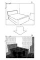
- FIG. 2 is a view showing how the photographing unit 18 photographs a physical space.
- the photographing unit 18 photographs the inside of a room surrounded by a plurality of surfaces (floor, wall, ceiling, etc.).
- a bed and a picture are arranged in the real space RS.
- the user captures an arbitrary place while moving with the image processing apparatus 10.
- the imaging unit 18 continuously captures the physical space RS based on a predetermined frame rate to generate a captured image.
- FIG. 3 is a view showing an example of a photographed image.
- the photographed image G1 a wall, a floor, a bed, and a picture within the photographing range of the photographing unit 18 are photographed as a photographed object.
- the screen coordinate axis (Xs axis-Ys axis) is set with the upper left of the captured image G1 as the origin Os, and the position in the captured image G1 is indicated by two-dimensional coordinates in the screen coordinate system.
- the image processing apparatus 10 extracts a feature point group from the captured image G1, and calculates three-dimensional coordinates of the feature point group in the observation space using the SLAM technique.
- a feature point is a point that indicates a characteristic portion in an image, and indicates, for example, a portion of an outline of a photographed object or a portion in which a color of the photographed object changes.
- a feature point group is a collection of a plurality of feature points.
- FIG. 4 is a diagram showing an example of three-dimensional coordinates of the feature point group.
- P1 to P16 shown in FIG. 4 are feature points extracted from the photographed image G1.
- the feature points P1 to P16 are collectively referred to as a feature point group P when it is not necessary to distinguish them in particular.
- a world coordinate axis (Xw-axis-Yw-axis-Zw-axis) is set with a predetermined position in the observation space OS as the origin Ow, and the position in the observation space OS is a three-dimensional coordinate of the world coordinate system. Indicated.
- the image processing apparatus 10 not only calculates three-dimensional coordinates of the feature point group P using the SLAM technique, but also estimates the position and orientation of the imaging unit 18 in the physical space RS.
- the image processing apparatus 10 sets three-dimensional coordinates of the feature point group P in the observation space OS, and sets the observation viewpoint OV in the observation space OS so as to correspond to the position and the orientation of the imaging unit 18.
- the observation viewpoint OV is also referred to as a virtual camera, and is a viewpoint in the observation space OS.
- the density of the feature point group P is high enough to represent the surface of the photographed object, as shown in FIG. It does not. That is, the observation space OS in which the three-dimensional coordinates of the feature point group P are set is sparse point group data, and does not have an amount of information that can express the surface of a photographed object in detail, for example.
- the image processing apparatus 10 estimates the three-dimensional shape of the photographed object using machine learning (deep learning), integrates the estimated three-dimensional shape and the three-dimensional coordinates of the feature point group P , And increase the amount of information in the observation space OS. Specifically, the image processing apparatus 10 roughly estimates the three-dimensional shape of the photographed object by machine learning, and corrects the estimated three-dimensional shape so as to match the three-dimensional coordinates of the feature point group P which is the actual measurement value. Do.
- the image processing apparatus 10 acquires two images of a depth image and a normal image as an estimation result of a three-dimensional shape of a photographed object.
- the estimation result may be expressed as two-dimensional information, and may not necessarily be expressed in an image format.
- the estimation result may be data indicating a combination of two-dimensional coordinates and information on depth or normal, and may be, for example, tabular data or tabular data.
- FIG. 5 is a view showing an example of the depth image.
- the depth image G2 is an image that has the same size as the captured image G1 (the same number of vertical and horizontal pixels), and indicates the depth of the captured object.
- the depth is the depth of the photographed object, and is the distance between the photographing unit 18 and the photographed object.
- the pixel value of each pixel of the depth image G2 indicates the depth of the pixel. That is, the pixel value of each pixel of the depth image G2 indicates the distance between the photographed object appearing in the pixel and the photographing unit 18.
- the pixel value is a numerical value assigned to each pixel, and is information also called color, luminance, or lightness.
- the depth image G2 may be a color image or a grayscale image.
- the pixel values of the depth image G2 are schematically represented by the density of halftone dots, and the deeper the halftone dots, the lower the depth (the shorter the distance), and the thinner the halftone dots, the depth It shows that it is high (the distance is long). That is, the photographed object indicated by the pixels with dark dots is located on the front side when the photographed object is seen from the photographing unit 18, and the photographed object indicated by the pixels with the light halftone dots is indicated behind the photographed object from the photographing unit 18. On the side. For example, the halftone dots of the bed and the like close to the photographing unit 18 become dark, and the halftone dots of the wall and the like far from the photographing unit 18 become thin.
- FIG. 6 is a view showing an example of a normal image generated from the photographed image G1.
- the normal image G3 is an image having the same size (the same number of vertical and horizontal pixels) as the photographed image G1 and indicating the normal of the photographed object.
- the normal is a straight line perpendicular to the surface of the object.
- the pixel value of each pixel of the normal image G3 indicates the direction (vector information) of the normal to the pixel. That is, the pixel value of each pixel of the normal image G3 indicates the direction of the normal to the object photographed by the pixel.
- the normal image G3 may be a color image or a grayscale image.
- the pixel values of the normal image G3 are schematically shown by the density of halftone dots, and the darker halftone dots indicate that the normal line is directed in the vertical direction (Zw axis direction), and the halftone dots are Indicates that the normal is directed in the horizontal direction (Xw axis direction or Yw axis direction). That is, the surface of the object to be photographed has a vertically oriented surface, and the object to be photographed has a surface horizontally directed.
- the halftone dots in the portion where the surface is directed in the vertical direction are thick
- the halftone dots in the portion where the surface is directed horizontally are thin
- the Xw-axis direction indicates the halftone dots more deeply than the Yw-axis direction. Therefore, for example, the surface of the wall on the right side (normal direction is in the Xw axis direction) when viewed from the photographing unit 18 indicates halftone dots more deeply than the surface of the wall on the left side (normal direction is in the Yw axis direction) .
- the depth image G2 and the normal image G3 are both pieces of information indicating the three-dimensional shape of the photographed object, and the image processing apparatus 10 can estimate the mesh of the photographed object based on these.
- the depth image G2 and the normal image G3 are information obtained by machine learning and have a certain degree of accuracy, since they are not actual measurement values measured on the spot by the image processing apparatus 10, the accuracy is high up to that point. Do not mean.
- the image processing apparatus 10 integrates the three-dimensional coordinates of the feature point group P, which is an actual measurement value, with the depth image G2 and the normal image G3 to improve the accuracy of the three-dimensional shape, and to observe the observation space OS. To increase the amount of information.
- FIG. 7 is a diagram showing an example of the integrated observation space OS.
- a collection of point clouds in the observation space OS is schematically shown by a solid line.
- the density of point clouds in the observation space OS can be increased, and the density of point clouds is high enough to represent the surface of a photographed object. That is, the integrated observation space OS is dense point cloud data, and has, for example, an amount of information capable of representing the surface of a photographed object in detail.
- the observation space OS is within the imaging range of the imaging unit 18 to the last, and the situation outside the imaging range (for example, a blind spot behind the imaging unit 18 or the like) is not reproduced. Therefore, in order to reproduce the entire room, the user holds the image processing apparatus 10 and shoots the room all over while moving, and the image processing apparatus 10 repeats the above-described processing to reproduce the entire room. It will be.
- the image processing apparatus 10 integrates the three-dimensional coordinates of the feature point group P, which is an actual measurement value, and the depth image G2 and the normal image G3 acquired using machine learning. This makes it possible to increase the amount of information in the observation space OS without using a configuration such as a depth camera.
- the details of the image processing apparatus 10 will be described.
- FIG. 8 is a functional block diagram showing an example of functions implemented in the image processing apparatus 10. As shown in FIG. As shown in FIG. 8, in the present embodiment, a case where the data storage unit 100, the photographed image acquisition unit 101, the observation space information acquisition unit 102, the machine learning unit 103, and the integration unit 104 are realized will be described.
- the data storage unit 100 is mainly implemented by the storage unit 12.
- the data storage unit 100 stores data necessary to generate an observation space OS that reproduces the state of the real space RS.
- the data storage unit 100 stores machine learning data used in machine learning.
- Machine learning data is data regarding features of various objects.
- the machine learning data is data indicating the feature of the appearance of the object, and various features such as a three-dimensional shape, an outline, a size, a color, or a pattern of the object may be indicated.
- the three-dimensional shape here means the unevenness
- Machine learning data stores feature information on features of the object for each object. Further, even if they are the same object, machine learning data may be prepared so as to cover various features because features such as three-dimensional shape, size, outline, color, or pattern are different. .
- the machine learning data stores feature information so as to cover known beds.
- depth image G2 and the normal image G3 are obtained by machine learning, it is assumed that the depth and the normal of the object are stored as the feature information. Therefore, depth learning data on the depth of an object and normal learning data on the normal of the object will be described as an example of machine learning data.
- depth learning data and normal learning data are generated by photographing an object with an RGB-D camera. Since the RGB-D camera can measure the depth of an object placed in the real space RS, depth learning data is generated based on depth information which is an actual measurement value. Further, since the depth of the object is information that can specify a three-dimensional shape (concave and convex on the surface of the object), the normal direction of the object surface can also be acquired based on the depth information measured by the RGB-D camera. For this reason, normal learning data is also generated based on the normal direction which is an actual measurement value.
- Machine learning data and machine learning algorithms themselves can use known data and algorithms. For example, “Predicting Depth, Surface Normals and Semantic Labels with a Common Multi-Scale Convolutional Architecture” (http: // www) Data and algorithms in so-called CNN (Convolutional Neural Network) described in .cs.nyu.edu / ⁇ deigen / dnl /, https://arxiv.org/pdf/1411.4734v4.pdf) may be used.
- the feature information stored in the machine learning data may be any feature of the object, and is not limited to the depth and the normal.
- the feature information may indicate the contour, size, color or pattern of the object.
- the data storage unit 100 stores observation space information indicating the appearance of the observation space OS.
- information on a photographed object and observation viewpoint parameters related to the observation viewpoint OV are stored.
- the information on the photographed object is a point cloud corresponding to the photographed object, and includes, for example, three-dimensional coordinates of the feature point group P and vertex coordinates of a mesh (three-dimensional object representing the photographed object).
- the observation viewpoint parameters are, for example, the position, the orientation, and the angle of view of the observation viewpoint OV.
- the direction of the observation viewpoint OV may be indicated by three-dimensional coordinates of the fixation point, or may be indicated by vector information indicating the gaze direction.
- the data stored in the data storage unit 100 is not limited to the above example.
- the data storage unit 100 may store the captured image G1 in time series.
- the data storage unit 100 may store two-dimensional coordinates of the feature point group P extracted from the captured image G1 in time series, or vector information indicating a position change of the feature point group P is time-series May be stored.
- the data storage unit 100 may store information on a three-dimensional object indicating an object to be synthesized.
- the object to be synthesized is a fictitious object displayed together with the photographed image G1, and is, for example, a fictitious animal (including a character imitating a person), furniture, home electronics, clothes, a vehicle, a toy, or sundries etc. is there.
- the object to be synthesized may move in the observation space OS, or in particular, may stand still without movement.
- the photographed image acquisition unit 101 is realized mainly by the control unit 11.
- the photographed image acquisition unit 101 acquires a photographed image G1 photographed by the photographing unit 18 movable in the physical space.
- Movable in the real space RS means that the position and orientation of the imaging unit 18 can be changed, for example, moving a housing including the imaging unit 18, changing the posture of the housing, or the like It means that it is possible to rotate the housing. In other words, it means that the imaging range (field of view) of the imaging unit 18 can be changed. Note that the photographing unit 18 does not have to keep moving at all times, but may remain temporarily at the current location and may not change in position and direction.
- the photographing unit 18 photographs the physical space RS based on a predetermined frame rate, so the photographed image acquisition unit 101 acquires a photographed image G1 photographed by the photographing unit 18 at a predetermined frame rate.
- the frame rate is the number of times of processing per unit time, and is the number of still images (number of frames) per unit time in a moving image.
- the frame rate may be a fixed value or may be specified by the user. For example, assuming that the frame rate is N fps (N: natural number, fps: Frames Per Second), the length of each frame is 1 / N seconds, and the imaging unit 18 captures the physical space RS for each frame that is a processing unit.
- the photographed image G1 is generated, and the photographed image acquisition unit 101 continuously acquires the photographed image G1 generated by the photographing unit 18.
- the photographed image acquisition unit 101 acquires the photographed image G1 photographed by the photographing unit 18 in real time. That is, the photographed image acquisition unit 101 acquires the photographed image G1 immediately after the photographing unit 18 generates the photographed image G1. The photographed image acquisition unit 101 acquires the photographed image G1 within a predetermined time from the time when the photographing unit 18 generates the photographed image G1.
- the captured image G1 may not be acquired in real time, and in this case, the captured image acquisition unit 101 may store image data stored in the data storage unit 100 (that is, still image data or moving image data that has been captured). ) May be acquired.
- the photographed image acquisition unit 101 may acquire image data from the computer or information storage medium.
- the frame rate may not be set in the photographing unit 18 in particular, and in the case of photographing irregularly, if the photographed image acquisition unit 101 acquires the photographed image G1 each time the photographing unit 18 photographs.
- the user may manually issue a photographing instruction from the operation unit 14.
- the photographing unit 18 generates a photographed image G1 each time the user instructs the photographing, and the photographed image acquisition unit 101 The photographed image G1 generated may be acquired each time the user gives a photographing instruction.
- the observation space information acquisition unit 102 is realized mainly by the control unit 11.
- the observation space information acquisition unit 102 acquires observation space information including three-dimensional coordinates of the feature point group P in the observation space OS based on the change in position of the feature point group P in the captured image G1.
- the change in position of the feature point group P is a change in position on the image, and is a change in two-dimensional coordinates.
- the positional change of the feature point group P is indicated by vector information (two-dimensional vector information) of the screen coordinate system. That is, the observation space information acquisition unit 102 acquires, for each feature point included in the feature point group P, vector information indicating a change in position of the feature point.
- the observation space information acquired by the observation space information acquisition unit 102 is information indicating the distribution of the feature point group P in the observation space OS, and is a so-called 3D map of the feature point group P.
- the observation space information at this stage as described with reference to FIG. 4, only the three-dimensional coordinates of the feature point group P are stored, and sparse points which can not represent the surface shape of the object to be photographed It becomes group data.
- the observation space information acquisition unit 102 extracts a feature point group P from the captured image G1, and tracks the extracted feature point group P.
- the feature point may be a point indicating the feature of the photographed object captured in the photographed image G1, and may be, for example, a point indicating a part of the outline of the photographed object, or a point inside the photographed object For example, it may be a center point).
- the feature point extraction method itself may be executed based on a known feature point extraction algorithm. For example, a point on the contour of the object detected by the contour extraction process may be used as a feature point, or the contour lines are predetermined A point intersecting at an angle or more may be used as a feature point, or an edge portion in an image may be used as a feature point.
- the observational space information acquisition unit 102 may also extract feature points based on an algorithm called Scale-Invariant Feature Transform (SIFT) (https://en.wikipedia.org/wiki/Scale-invariant_feature_transform).
- SIFT Scale-Invariant Feature Transform
- ORB Oriented fast and Rotated Brief: http://www.willowgarage.com/sites/default/files/orb_final.pdf). According to these algorithms, parts other than the corners and edges of the object may be extracted as feature points.
- the relationship between the positional change of the feature point group P and the three-dimensional coordinates is assumed to be stored in advance in the data storage unit 100 as a mathematical expression, a table, or a part of a program code. Since the positional change of the feature point group P is two-dimensional information, this relationship can also be referred to as a conversion rule for converting two-dimensional information into three-dimensional information.
- the observation space information acquisition unit 102 acquires three-dimensional coordinates associated with the position change of the feature point group P.
- the observation space information acquisition unit 102 acquires observation space information using the SLAM technique.
- the feature point moves on the image in the opposite direction to the direction in which the imaging unit 18 moved with respect to the object in the real space RS. Furthermore, the farther the photographed object is, the smaller the amount of movement of the feature point on the image.
- the three-dimensional coordinates of the feature point group P are calculated using the principle of triangulation based on these tendencies. That is, the observation space information acquisition unit 102 tracks the feature point group P, and calculates three-dimensional coordinates of the feature point group P based on the SLAM technique using the triangulation principle.
- the observation space information acquisition unit 102 estimates the position of the imaging unit 18 based on the change in position of the feature point group P, and sets the observation viewpoint OV in the observation space OS based on the estimation result. For example, the observation space information acquisition unit 102 estimates the current position and orientation of the imaging unit 18, and reflects the estimation result on the position and orientation of the observation viewpoint OV.
- the relationship between the positional change of the feature point group P and the position and orientation of the photographing unit 18 is stored in the data storage unit 100 in advance as a mathematical expression, a table, or a part of a program code. This relationship can also be said to indicate a relationship between two-dimensional vector information indicating the change of the feature point group P, and three-dimensional coordinates indicating the position of the observation viewpoint OV and three-dimensional vector information indicating the direction.
- the observation space information acquisition unit 102 acquires three-dimensional coordinates and three-dimensional vector information associated with the change in position of the feature point group P.
- the observation space information acquisition unit 102 sets the observation viewpoint OV
- the observation viewpoint OV moves in the observation space OS in the same manner as the imaging unit 18. That is, the position and the orientation of the observation viewpoint OV in the observation space OS change in the same manner as the position and the orientation of the imaging unit 18 in the real space RS.
- a method of estimating the position and orientation of the imaging unit 18 itself may be a known viewpoint estimation method, and may use, for example, SLAM technology.
- the machine learning unit 103 is mainly implemented by the control unit 11.
- the machine learning unit 103 acquires additional information on the feature of the photographed object shown in the photographed image G1 based on the machine learning data on the feature of the object.
- the additional information indicates the feature of the appearance of the photographed object, and may be, for example, information such as a three-dimensional shape, classification (type), color, or pattern of the photographed object.
- information on the three-dimensional shape of a photographed object estimated based on machine learning data will be described as an example of the additional information.
- the information on the three-dimensional shape of the object to be photographed may be information that can three-dimensionally identify the unevenness or the direction of the surface of the object to be photographed.
- information on the mesh of the object to be photographed or information on the normal of the object to be photographed It is.
- the information on the three-dimensional shape of the object to be photographed is surface information indicating the surface of the object to be photographed.
- the information on the mesh of the object to be photographed may be any information that can represent the mesh in the observation space OS, and may be, for example, dense point group data or vertex coordinates themselves constituting the mesh.
- the depth may be such that the vertex coordinates can be identified.
- “dense” is to have a density (density above a certain value) that can express the surface shape of the object to be photographed, and, for example, with a vertex of a common mesh in computer graphic technology It is to have a similar density.
- the depth is the depth of the mesh when viewed from the observation viewpoint OV, and is the distance between the observation viewpoint OV and each vertex of the mesh.
- the information on the normal to the object to be photographed may be any information that can specify the normal to the surface of the object to be photographed, and may be vector information on the normal, for example.
- the Xw-Yw plane), the normal, and the crossing angle may be used.
- the additional information may be any data format, but in the present embodiment, the position (two-dimensional coordinates in the screen coordinate system) of the photographed object in the photographed image G1 and the feature amount related to the photographed object are associated 2
- the case of dimensional feature amount information will be described.
- a feature amount image in which a feature amount related to a photographed object is associated with each pixel will be described.
- the feature amount of each pixel of the feature amount image is a numerical value representing the feature of the pixel, and is, for example, the depth of the photographed object estimated based on the machine learning data. That is, the depth image G2 is an example of the feature amount image.
- the feature amount is not limited to the depth.
- the feature amount of the feature amount image may be a normal of a photographed object estimated based on the machine learning data. That is, the normal image G3 is also an example of the feature amount image.
- the machine learning unit 103 specifies an object similar to the photographed object from among the objects shown in the machine learning data. Similar means that the appearance is similar, for example, the shape may be similar, or both the shape and the color may be similar.
- the machine learning unit 103 calculates the similarity between the object shown in the machine learning data and the photographed object, and determines that the object and the photographed object are similar when the similarity is equal to or greater than a threshold. The similarity may be calculated based on the difference in shape and the difference in color.
- the machine learning unit 103 acquires additional information based on feature information associated with an object similar to a photographed object. For example, when a plurality of similar objects are identified from the captured image G1, the machine learning unit 103 acquires additional information including a plurality of pieces of feature information respectively corresponding to the plurality of objects.
- the machine learning unit 103 specifies an object similar to the photographed object from among the objects indicated in the depth learning data. Then, the machine learning unit 103 generates a depth image G2 by setting a pixel value indicating the depth associated with the specified object to the pixel of the photographed object in the photographed image G1. That is, the machine learning unit 103 sets the depth associated with the object similar to the photographed object for each area where the photographed object appears in the photographed image G1.
- the machine learning unit 103 specifies an object similar to the photographed object from among the objects indicated in the normal learning data. Then, the machine learning unit 103 generates a normal image G3 by setting a pixel value indicating vector information of a normal associated with the specified object to the pixel of the object in the captured image G1. . That is, the machine learning unit 103 sets, for each area where a photographed object appears in the photographed image G1, vector information associated with an object similar to the photographed object.
- the observation space information acquisition unit 102 and the machine learning unit 103 may execute the processing based on the captured image G1 captured in different frames, but in the present embodiment, the images captured in the same frame are captured
- the photographed image G1 referred to by the observation space information acquisition unit 102 to acquire observation space information and the photographed image G1 referred to by the machine learning unit 103 to acquire additional information are the same, and the same viewpoint It is assumed that the image is taken at (the position and the orientation of the imaging unit 18).
- the integration unit 104 is mainly implemented by the control unit 11.
- the integration unit 104 integrates observation space information and additional information. Integration means increasing the amount of information in the observation space OS based on the observation space information and the additional information. For example, increasing the number of point groups more than the observation space OS indicating the three-dimensional coordinates of the feature point group P, and for the three-dimensional coordinates of the feature point group P, information other than three-dimensional coordinates (for example, normal information) Adding or adding information while adding point clouds by combining them corresponds to integration.
- the integration unit 104 may generate new information based on the observation space information and the additional information, or may add the additional information to the observation space information instead of generating new information. For example, the integration unit 104 increases the number of point groups indicated by the observation space information to obtain dense point group data, or information such as normal information with respect to three-dimensional coordinates of the feature point group P indicated by the observation space information. Or combining them to add information such as normal information while making observation space information into dense point group data.
- the integration unit 104 is based on the additional information with respect to observation space information (sparse point group data) indicating three-dimensional coordinates of the feature point group P. The case of adding information on the three-dimensional shape will be described.
- the integration unit 104 can perform two-dimensional observation information indicating that the observation space OS is viewed from the observation viewpoint OV, and two-dimensional feature quantity information. Execute processing based on the comparison result of.
- the two-dimensional observation information is information obtained by projecting the observation space OS, which is a three-dimensional space, onto the two-dimensional space, and is information obtained by two-dimensionally converting three-dimensionally expressed information.
- the position (two-dimensional coordinates) of the feature point group in the two-dimensional space and the depth of the feature point group in the observation space OS are associated.
- the two-dimensional coordinates of the feature point group may be indicated by real numbers. That is, the two-dimensional coordinates of the feature point group need not be indicated by integers alone, but may be indicated by numerical values including decimals.
- feature amount images (for example, the depth image G2 and the normal image G3) are used as two-dimensional feature amount information, so for example, the integration unit 104 looks at the observation space OS from the observation viewpoint OV.
- the integration unit 104 combines these dimensions and executes the process. Note that the integration unit 104 does not convert observation space information into two-dimensional information, but instead projects feature quantity images onto the observation space OS to make it three-dimensional information as in a modification described later. Processing may be performed.
- FIG. 9 is a diagram showing an example of an observation space image.
- FIG. 9 shows the observation space OS in the state of FIG. 4 as viewed from the observation viewpoint OV, and the feature point group P appearing in the observation space image G4 is schematically shown by a circle of a certain size.
- each feature point may be represented by only one or several pixels.
- the position of the feature point may not be represented by an integer value indicating the position of the pixel, but may be represented by a float value capable of expressing the decimal part.
- the integration unit 104 generates the observation space image G4 by converting three-dimensional coordinates of the feature point group P into two-dimensional coordinates of the screen coordinate system. Therefore, the observation space image G4 can be said to be a 2D projection view in which the observation space OS which is three-dimensional information is projected onto the two-dimensional information.
- this conversion processing itself, known coordinate conversion processing (geometry processing) can be applied.
- the observation space image G4 indicates the depth of the feature point group P in the observation space OS. That is, the pixel value of the observation space image G4 indicates the depth as in the depth image G2. In the observation space image G4, in particular, no pixel value may be set for a portion where the feature point group P does not appear, or a predetermined value indicating that the feature point group P is not displayed is set. It is also good.
- the observation space image G4 has the same size (the same number of vertical and horizontal pixels) as the photographed image G1, and may be a color image or a gray scale image.
- the pixel values of the observation space image G4 are schematically represented by the density of halftone dots, and the deeper the halftone dots, the lower the depth (the shorter the distance), and the thinner the halftone dots, the depth Is high (the distance is long).
- halftone dots of pixels indicating feature points P5 to P7 close to the observation viewpoint OV are thick
- halftone dots of pixels indicating feature points P11 to P15 not far from the observation viewpoint OV are medium darkness.
- the halftone dots of the feature points P1 to P4 and P8 to P10 and P14 far from the observation viewpoint OV are thin.
- the integration unit 104 identifies a pixel where the feature point group P appears in the observation space image G4, and executes processing based on the pixel value of the pixel of the feature amount image (for example, the depth image G2 and the normal image G3). .
- the integration unit 104 specifies two-dimensional coordinates of pixels in which the feature points P1 to P15 appear in the observation space image G4, and based on the pixel values of pixels of the two-dimensional coordinates of the feature amount image. Execute the process.
- FIG. 10 is a diagram illustrating an example of processing performed by the integration unit 104.
- the integration unit 104 sets the mesh M in the observation space OS based on the depth image G2.
- the integration unit 104 projects the depth of each pixel indicated by the depth image G2 onto the observation space OS, and the temporary mesh M (as an initial value) such that a location away from the observation viewpoint OV by the depth becomes vertex coordinates.
- Set the mesh M That is, the integration unit 104 converts the depth of each pixel of the depth image G2 into three-dimensional coordinates, and sets the three-dimensional coordinates as vertex coordinates of the mesh M.
- various known methods can be applied as the method itself of setting a point group in a three-dimensional space based on depth information and converting it into a mesh.
- various known methods can be applied to the method itself for converting depth information, which is so-called 2.5-dimensional information, into three-dimensional point cloud data.
- the mesh M may be set in the observation space OS.
- the integration unit 104 changes the scale of the mesh M based on the comparison result of the observation space image G4 and the depth image G2. That is, the integration unit 104 identifies a portion corresponding to the feature point group P from the mesh M, and changes the scale of the mesh M such that the identified portion approaches the feature point group P.
- the scale is a parameter that affects the position and size of the mesh M.
- the distance between the point groups constituting the mesh M changes, and the distance between the mesh M and the observation viewpoint OV changes.
- the scale is increased, the distance between the point groups is expanded as a whole, and the mesh M is increased, or the distance between the mesh M and the observation viewpoint OV is increased.
- the scale is reduced, the distance between the point groups is reduced as a whole to reduce the mesh M or to shorten the distance between the mesh M and the observation viewpoint OV.
- the integration unit 104 calculates an index value while changing the scale, and determines whether the index value is less than a threshold. If the index value is equal to or greater than the threshold, the integration unit 104 changes the scale again and performs the determination process again. On the other hand, when the index value is less than the threshold, the integration unit 104 determines the current scale. The integration unit 104 changes the mesh M so that the overall degree of deviation between the feature point group P and the mesh M is reduced by determining the scale in this manner.
- the integration unit 104 changes the scale and changes the mesh M as a whole, the mesh M is partially based on the changed mesh M and the feature point group P. It may be changed. For example, the integration unit 104 determines, for each feature point, whether the distance between the feature point and the mesh M is equal to or greater than a threshold. If the distance is equal to or more than the threshold, the integration unit 104 changes the mesh M corresponding to the feature point so as to approach the feature point. Partial modification of the mesh M is performed by changing three-dimensional coordinates of some of the vertices (vertices near the target feature point).
- the process performed by the integration unit 104 is not limited to the above example.
- the integration unit 104 may change the mesh M again based on the normal image G3 after changing the mesh M based on the depth image G2.
- the integration unit 104 acquires normal information of the mesh M changed based on the depth image G2, and compares it with the normal information indicated by the normal image G3.
- the integration unit 104 partially changes the mesh M so as to reduce the difference between the two.
- the integration unit 104 compares the observation space image G4 with the normal image G3 by the same processing as the depth image G2 to obtain the correspondence between the mesh M and the normal information indicated by the normal image G3. It should be identified.
- the integration unit 104 of the present embodiment sets the mesh M of the object to be observed in the observation space OS based on the two-dimensional feature information, and compares the two-dimensional observation information with the two-dimensional feature information. Change the scale of mesh M based on. For example, the integration unit 104 sets a mesh in the observation space OS based on the additional information, and changes the mesh based on the observation space information.
- the integration unit 104 partially changes the mesh M after changing the scale of the mesh M based on the comparison result of the two-dimensional observation information and the two-dimensional feature amount information. Also, for example, the integration unit 104 sets the mesh M of the object to be observed in the observation space OS based on the depth image G2, and changes the scale of the mesh M based on the comparison result of the observation space image G4 and the depth image G2. Do. Furthermore, the integration unit 104 partially changes the mesh M after changing the scale of the mesh M based on the comparison result of the observation space image and the feature image (for example, the depth image G2 and the normal image G3). Do.
- the integration unit 104 may change the mesh portion around the mesh portion after changing the mesh portion corresponding to the three-dimensional coordinates of the feature point group indicated by the observation space information in the mesh M.
- the surrounding means a portion within a predetermined distance.
- the integration unit 104 changes the mesh portion so that the mesh portion between the feature points becomes smooth. Do.
- smooth means, for example, that the change in unevenness does not become too rapid, and the change in position is less than the threshold.
- the integration unit 104 changes the mesh portion so that the change in the unevenness of the mesh M is less than the threshold.
- the change method of the mesh part may use the well-known technique, for example, "As-Rigid-As-Possible Surface Modeling" (http://igl.ethz.ch/projects/ARAP/arap_web. A method called ARAP described in pdf) may be used.
- ARAP described in pdf
- the ARAP method may be used as it is, in this embodiment, the case where the ARAP method is expanded and the mesh M is changed based on the reliability of mesh estimation will be described.
- the integration unit 104 may maintain the shape without changing much the highly reliable portion, and may change the shape by changing the portion with low reliability to some extent.
- reliability refers to the accuracy of shape estimation and how similar it is to the surface shape of the subject.
- the estimation accuracy of the mesh M is often high because the surface is clearly shown in the captured image G1.
- the estimation accuracy of the mesh M may be low because the surface is not captured so much in the captured image G1. Therefore, in the present embodiment, in the mesh M, the part facing the observation viewpoint OV is highly reliable, and the part not facing the observation viewpoint OV (a part facing transversely to the observation viewpoint OV) is It should be unreliable.
- 11 and 12 are explanatory diagrams of a process of changing the mesh M by expanding the ARAP method.
- the reliability is higher as the angle ⁇ between the normal vector n of the vertex of the mesh M, the observation viewpoint OV and the vector d connecting the vertex is closer to 180 °.
- the mesh M does not face the opposite direction of the observation viewpoint OV, and in principle, the angle ⁇ is not smaller than 90 °.
- the integration unit 104 changes the mesh portion based on the orientation (angle ⁇ ) of the mesh portion with respect to the observation viewpoint OV. That is, the integration unit 104 determines the change amount of the mesh portion based on the orientation of the mesh portion with respect to the observation viewpoint OV.
- the change amount of the mesh portion is how much the shape is deformed, and is the change amount (movement amount) of the three-dimensional coordinates of the vertex.
- the relationship between the direction with respect to the observation viewpoint OV and the change amount of the mesh portion is stored in the data storage unit 100 in advance.
- the relationship may be stored as data in the form of a mathematical expression or a table, or may be described as part of a program code.
- the integration unit 104 changes each mesh portion of the mesh M based on the amount of change associated with the orientation of the mesh portion with respect to the observation viewpoint OV.
- the integration unit 104 reduces the amount of change in the mesh portion, and the mesh portion does not face the observation viewpoint OV ( As the angle ⁇ approaches 90 °), the amount of change in the mesh portion is increased. In other words, the integration unit 104 increases the rigidity of the mesh portion as the mesh portion faces the observation viewpoint OV, and the rigidity of the mesh portion decreases as the mesh portion does not face the observation viewpoint OV. Do. If the mesh portion does not face the observation viewpoint OV, it means that the mesh portion faces the observation viewpoint OV.
- the mesh M is unnaturally deformed so as to be pulled by the feature point P as shown in FIG. Sometimes.
- the above unnatural deformation is A more natural mesh M can be obtained.
- the vertex of the mesh M corresponding to the feature point P is described as v i .
- the vertex v i is the vertex closest to the point of intersection of the mesh M and the straight line connecting the observation viewpoint OV and the feature point P (dotted line of the vector d in FIG. 11).
- the integration unit 104 may change the mesh M based on Formula 1-7 below.
- Formula 1-7 (especially Formula 3-4) is an example of the relationship between the direction to the observation viewpoint OV described above and the amount of change of the mesh portion.
- the integration unit 104 calculates, for each vertex v i , the value of the energy function shown on the left side of Formula 1 below.
- Equation 1 the neighborhood corresponding to the vertex v i is described as C i, and each vertex of the neighborhood is described as v j .
- the neighborhood is a vertex around the vertex v i , and here, it is an adjacent vertex (one-ring neighborhood), but a vertex separated by two or more may correspond to the neighbor.
- the neighboring changed C' vertices after the change v described as i, describes the adjacent vertexes of the modified and v 'j.
- N (v i ) on the right side of Equation 1 is a collection of adjacent vertices v j included in the neighborhood C i of the vertex v i .
- R i on the right side of Formula 1 is a 3 ⁇ 3 rotation matrix.
- the energy function E (C ′ i ) is a sum of values obtained by multiplying the relative positional change of the adjacent vertex v j with respect to the vertex v i by the weighting coefficient ⁇ ij . Even if the adjacent vertex v j moves largely with respect to the vertex v i , if the weighting coefficient ⁇ ij is small, the value of the energy function E (C ′ i ) decreases. Conversely, even if the adjacent vertex v j does not move much with respect to the vertex v i , if the weighting coefficient ⁇ ij is large, the value of the energy function E (C ′ i ) becomes large.
- the weighting factor ⁇ ij is determined by the combination of the vertex v i and the adjacent vertex v j .
- the integration unit 104 calculates the weighting coefficient ⁇ ij based on Equation 2 below.
- ⁇ ij and ⁇ ij on the right side of Equation 2 are angles on the opposite side of the edge (i, j) of the mesh M.
- the integration unit 104 calculates the total value of the energy functions E (C ′ i ) calculated for each vertex v i based on Equation 3 below.
- Equation 3 the modified mesh M is described as M ′.
- the integration unit 104 calculates, for each vertex v i , a value obtained by multiplying the value of the energy function E (C ′ i ) by the weighting coefficient ⁇ i , and calculates the total value thereof.
- the weighting factor ⁇ i may be determined using, for example, a sigmoid function.
- the integration unit 104 calculates the weighting factor ⁇ i based on Equation 4 below.
- a and b are coefficients, which are fixed values.
- the weighting factor ⁇ i increases as the angle ⁇ approaches 180 °, and the influence of the change of the mesh portion on the total value of the energy function (left side of Formula 3) increases. For this reason, the total value of the energy function will be greatly increased by changing the mesh part a little.
- the weighting factor ⁇ i decreases as the angle ⁇ approaches 90 °, and the influence of the change of the mesh portion on the total value of the energy function decreases. For this reason, even if the mesh portion is largely changed, the total value of the energy function does not increase so much.
- the integration unit 104 may change the mesh M so that the total value of the energy functions E (C ′ i ) calculated by Equation 3 becomes smaller, but the integration unit 104 further considers the bending coefficient. May be The bending coefficient is a numerical value indicating how much the mesh M surface is bent (deformed). For example, “Z. Levi and C. Gotsman. Smooth rotation enhanced as-rigid-as-possible mesh animation. IEEE Transactions on. As described in Visualization and Computer Graphics, 21: 264-277, 2015. ", it is calculated based on Equation 5 below.
- ⁇ is a weighting coefficient
- A means a surface whose characteristics do not change even if the scale is changed.
- R i and R j on the right side of Formula 1 are 3 ⁇ 3 rotation matrices.
- the integration unit 104 calculates the bending coefficient B ij for each combination of the vertex v i and the adjacent vertex v j, and reflects it on the total value of the energy function E (C ′ i ) based on Equation 6 below. May be
- the integration unit 104 since the captured image G1 is repeatedly acquired under a predetermined frame rate, and the integration unit 104 repeatedly executes the above-described process, the integration unit 104 considers the scale calculated in the past, and the following equation Based on 7, the absolute scale s w t of the observation space OS at time t may be calculated. Note that s c t on the right side of Formula 7 is a scale set to the mesh M.
- FIG. 13 is a flow chart showing an example of processing executed by the image processing apparatus 10.
- the processing illustrated in FIG. 13 is executed by the control unit 11 operating according to the program stored in the storage unit 12.
- the process illustrated in FIG. 13 is an example of a process performed by the functional block illustrated in FIG. 8 and is performed for each frame captured by the imaging unit 18.
- the control unit 11 tracks the feature point group P extracted from the captured image G1, and sets three-dimensional coordinates of the feature point group P and the observation viewpoint OV in the observation space OS by using the SLAM technique. Do.
- the control unit 11 executes a photographed image acquisition process (S1).
- S1 the control unit 11 acquires a photographed image G1 generated by the photographing unit 18 in the current frame.
- the control unit 11 may record the captured image G1 in the storage unit 12 in time series. That is, the control unit 11 may record the history of the captured image G1 in the storage unit 12.
- the control unit 11 executes 2D tracking processing based on the captured image G1 acquired in S1 (S2).
- the 2D tracking process is a process for tracking a change in position of the feature point group P on the image.
- the control unit 11 acquires a feature point group P from the captured image G1 acquired in S1.
- the control unit 11 specifies the correspondence between the feature point group P and the feature point group P of the captured image G1 acquired in the closest frame (the frame immediately preceding), Acquire vector information indicating the difference between two-dimensional coordinates.
- the control unit 11 records the two-dimensional coordinates of the feature point group P extracted in S2 in the storage unit 12 in association with the captured image G1. Further, the control unit 11 may record the vector information of the feature point group P in the storage unit 12 in time series.
- the control unit 11 determines whether to start the mapping process (S3).
- the mapping process is a process for updating observation space information (three-dimensional coordinates of the feature point group P).
- the mapping process may be performed every frame or may be performed once for a plurality of frames.
- the execution interval of the mapping process may be a fixed value or a variable value.
- mapping process is started again in the next frame after the previous mapping process is completed. Therefore, in S3, it is determined whether the previous mapping process has ended, and if the previous mapping process has ended, it is determined to start the mapping process, and if the previous mapping process has not ended, the mapping process is started Then it does not judge.
- the control unit 11 starts the mapping process based on the captured image G1 acquired in S1 (S4).
- the mapping process started at S4 is executed in parallel (or in the background) with the main routine process shown in FIG.
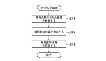
- FIG. 14 is a flowchart showing an example of the mapping process.
- the control unit 11 calculates three-dimensional coordinates of the feature point group P based on the execution result of the 2D tracking process performed in S2 (S41).
- the control unit 11 calculates the accumulation of the movement amount of the feature point group P from the previous mapping process, and calculates three-dimensional coordinates of the feature point group P using the SLAM technique.
- the control unit 11 estimates the position of the imaging unit 18 based on the execution result of the 2D tracking process performed in S2 (S42). In S42, the control unit 11 calculates the accumulation of the movement amount of the feature point group P from the previous mapping process, and calculates the position and orientation of the imaging unit 18 using the SLAM technique.
- the control unit 11 updates the observation space information based on the calculation results of S41 and S42 (S43).
- the control unit 11 determines the three-dimensional coordinates of the feature point group P and the observation viewpoint parameters based on the three-dimensional coordinates of the feature point group P calculated in S41 and the position and orientation calculated in S42. Update.
- the restoration process is a process of estimating a three-dimensional shape of a photographed object by machine learning, and in the present embodiment, is a process of acquiring a depth image G2 and a normal image G3.
- the restoration process may be performed every frame or may be performed once for a plurality of frames.
- the execution interval of the restoration process may be a fixed value or a variable value.
- the restoration process may have a larger amount of calculation (more load) than the mapping process, and in this case, the execution interval of the restoration process may be longer than the mapping process.
- the mapping process may be performed once in two frames, and the restoration process may be performed once in three frames.
- the control unit 11 starts the restoration process based on the same captured image G1 as the mapping process in progress (S6).
- the restoration process started at S6 is executed in parallel (or in the background) with the main routine process shown in FIG.
- FIG. 15 is a flowchart showing an example of the restoration process.
- the control unit 11 acquires a depth image G2 based on the photographed image G1 and depth learning data (S61).
- the control unit 11 identifies a portion similar to the object indicated by the depth learning data from the captured image G1.
- the control unit 11 generates the depth image G2 by setting the depth of the object indicated by the depth learning data as the pixel value of each pixel of the part.
- the control unit 11 acquires the normal image G3 based on the photographed image G1 and the normal learning data (S62). In S62, the control unit 11 identifies a portion similar to the object indicated by the normal learning data from the captured image G1. Then, the control unit 11 generates the normal image G3 by setting the vector information of the normal of the object indicated by the normal learning data as the pixel value of each pixel of the part.
- the integration process is a process of setting a mesh of a photographed object in the observation space OS.
- the integration process may be performed every frame or may be performed once for a plurality of frames.
- the execution interval of the integration process may be a fixed value or a variable value.
- the control unit 11 starts the integration process (S8).
- the integration process started at S8 is performed in parallel (or in the background) with the main routine process shown in FIG.
- FIG. 16 is a flowchart showing an example of the integration process.
- the control unit 11 generates an observation space image G4 showing a state in which the feature point group P in the observation space OS is viewed from the observation viewpoint OV (S81).
- the observation space image G4 is an image similar to the depth image G2, and each pixel indicates the depth of the feature point group P.
- the control unit 11 generates the observation space image G4 by calculating the distance between the observation viewpoint OV and the feature point group P.
- the control unit 11 corrects the mesh indicated by the depth image G2 based on the observation space image G4 generated in S81 (S82).
- the control unit 11 specifies the position of the mesh corresponding to the feature point group P based on the observation space image G4 and the depth image G2, and scales the mesh so that the difference between these depths is reduced.
- the control unit 11 locally corrects the mesh so that the distance is smaller than the threshold.
- the control unit 11 corrects the mesh portion around the mesh portion matched with the feature point group P so as to be smooth.
- the control unit 11 may change the mesh portion based on the orientation of the mesh portion with respect to the observation viewpoint OV.
- the control unit 11 corrects the mesh corrected in S82 again based on the normal image G3 (S83).
- the control unit 11 specifies the normal direction corresponding to the feature point group P based on the observation space image G4 and the depth image G2, and corrects the normal of the mesh corrected in S82 (feature points of the mesh The mesh is corrected so that the difference between the normal of the portion corresponding to the group P and the normal indicated by the normal image G3 is reduced.
- the control unit 11 updates the observation space OS based on the mesh corrected in S83 (S84).
- the control unit 11 stores the vertex coordinates of the mesh corrected in S83 in the observation space information.
- observation space information which is sparse point cloud data in the mapping process becomes dense point cloud data by the integration process.
- the control unit 11 arranges a three-dimensional object representing a fictitious object in the observation space OS and terminates the observation space OS from the observation viewpoint OV before the processing is completed.
- a virtual image indicating the appearance of viewing may be generated, combined with the captured image G1, and displayed on the display unit 15.
- the captured image G1 to be synthesized at that time may be one obtained in S1 of the main frame, or may be the captured image G1 referred to in the mapping processing and the restoration processing.
- objects indicating moving objects such as balls and vehicles may be combined. In this case, the collision determination of the mesh in the observation space OS and the object indicating the moving object may be performed, and the moving object may bounce or climb a wall.
- mapping process and the restoration process do not have to be performed every frame, but may be performed once for a plurality of frames. Furthermore, since the restoration process may have more computational complexity than the mapping process, the execution interval of the restoration process may be longer than the execution interval of the mapping process.
- FIG. 17 is a diagram illustrating an example of the execution interval of each process.
- the captured image acquisition process (S1) and the 2D tracking process (S2) are executed every frame.
- the mapping process (FIG. 14) is performed once for n (n is an integer of 2 or more) frames, and the restoration process is performed once for m (m is an integer of 2 or more, m> n) frames Be done.
- the integration process will be executed after the completion of the restoration process.
- the photographed image G1 referred to in the mapping process and the restoration process is the photographed image G1 acquired in the same frame, and the mapping process is performed based on the photographed image G1 acquired from the same viewpoint.
- the restoration process is to be performed.
- a configuration for enhancing the information amount of the observation space OS by integrating the photographed image G1 photographed by the photographing unit 18 and the additional information obtained by the machine learning It can be simplified.
- information other than the three-dimensional coordinates of the feature point group P can be added to the observation space OS without using a special sensor such as a depth camera. For this reason, even if it is terminals, such as a smart phone which is not mounted with a special sensor, observation space OS with high accuracy can be generated.
- the image processing apparatus 10 sees from the same viewpoint by comparing the observation space image G4 and the feature amount image. Images can be compared with each other. That is, in the prior art, an RGB-D camera in which two cameras are arranged in parallel is used, and an error occurs in the observation space OS due to a difference in viewpoint position. However, the image processing apparatus 10 uses the same viewpoint Therefore, it is possible to prevent the occurrence of an error and to improve the reproducibility of the observation space OS.
- the feature amount image for example, the depth image G2 or the normal image G3
- the image processing apparatus 10 sees from the same viewpoint by comparing the observation space image G4 and the feature amount image. Images can be compared with each other. That is, in the prior art, an RGB-D camera in which two cameras are arranged in parallel is used, and an error occurs in the observation space OS due to a difference in viewpoint position. However, the image processing apparatus 10 uses the same viewpoint Therefore, it is possible to prevent the occurrence of an error and to improve the reproducibility of the observation space OS.
- the image processing apparatus 10 can bring the mesh obtained by machine learning closer to the actual measurement value by changing the scale of the mesh based on the comparison result of the observation space image G4 and the depth image G2.
- the repeatability of the observation space OS can be enhanced by simple processing. For example, instead of changing the mesh vertices one by one individually, since the mesh is brought closer to the actual measurement value as a whole by changing the scale, simplification of processing (reduction of computational complexity) is realized, and the image processing apparatus The processing speed can be improved while reducing the processing load of 10.
- the mesh is partially adjusted after changing the scale of the mesh, it is possible to more effectively reproduce the observation space OS. Also in this case, it is possible to realize simplification of the process for enhancing the reproducibility of the observation space OS by targeting only the large part of the difference instead of changing the mesh part individually for all the feature point groups P. Therefore, the processing load of the image processing apparatus 10 can be reduced more effectively, and the processing speed can be improved.
- the three-dimensional shape of the object can be reproduced by the observation space OS, and the three-dimensional shape of the real space RS is reproduced by the observation space OS in detail Can be simplified.
- a mesh representing the photographed object can be arranged in the observation space OS, and a mesh indicating an object in the real space RS is arranged in the observation space OS.
- the configuration can be simplified.
- the observation space OS is sparse but highly accurate because it is based on observation data
- the additional information is a predicted value using machine learning, so correctness may be low, although it is sparse.
- the reproducibility of observation space OS can be raised effectively by changing the said mesh based on the observation space information which is a measurement value.
- the mesh representation shape can be smoothed by changing the mesh portion around the mesh portion. That is, it is possible to improve the data accuracy as the data for storing the feature points, and it is possible to effectively improve the reproducibility of the observation space OS.
- the highly reliable mesh portion is integrated while maintaining its shape as much as possible, and the mesh portion with low reliability is Since the shape can be changed and integrated, the degree of reproducibility of the observation space OS can be effectively improved.
- the normal to the observation space OS can be set, and the three-dimensional shape of the object to be photographed can be represented.
- the configuration for reproducing in the observation space OS can be simplified.
- observation space information and additional information from the photographed image G1 of the same frame, the correspondence between the images of the same viewpoint can be specified, and the occurrence of an error due to the difference in viewpoint position as described above It is possible to prevent and improve the accuracy of the observation space OS more effectively.
- the depth or the normal of the photographed object is described as an example of the additional information, but the additional information may be information on the classification of the photographed object. That is, the additional information may be information in which each pixel of the captured image G1 is grouped for each captured object.
- the additional information may be information in which each pixel of the captured image G1 is grouped for each captured object.
- a case where a feature amount image is used will be described, and a classified image in which each pixel of the captured image G1 is classified will be described as an example of the feature amount image.
- FIG. 18 is a diagram showing an example of a classified image.
- the classified image G5 has the same size (the same number of vertical and horizontal pixels) as the photographed image G1, and is an image obtained by grouping the regions in the image for each photographed object.
- a pixel value is assigned to each photographed object. That is, the classified image G5 is a label image in which information for identifying a photographed object is added to each pixel. Pixels with the same pixel value indicate the same photographic subject.
- the classified image G5 may be a color image or a grayscale image.
- the pixel values of the classified image G ⁇ b> 5 are schematically represented by the darkness of halftone dots, and the pixels having the same darkness of halftone dots indicate the same object. Therefore, the pixel indicating the bed has a first pixel value.
- a pixel indicating a wall is a second pixel value
- a pixel indicating a floor is a third pixel value
- a pixel indicating a picture is a fourth pixel value.
- the integration unit 104 groups the feature point group P indicated by the observation space information based on the classified image G5. For example, the integration unit 104 generates the observation space image G4 and specifies the pixels in the classified image G5 corresponding to the feature point group P, as in the method described in the embodiment. Then, the integration unit 104 specifies the pixel value of each pixel in the classified image G5, and classifies feature points indicating the same value as the same group. That is, the integration unit 104 adds information for identifying a group to the three-dimensional coordinates of the feature point group P.
- the point cloud of the observation space OS can be grouped by using the information on the classification of the photographed object as the additional information.
- the integration unit 104 may add normal information to the three-dimensional coordinates of the feature point group P.
- FIG. 19 is a diagram illustrating an example of processing performed by the integration unit 104.
- the integration unit 104 adds normal information corresponding to the feature point to each feature point.
- the integration unit 104 may specify the correspondence between the feature point and the normal line information by comparing the observation space image G4 with the normal line image G3.
- the integration unit 104 maps normal information on a straight line connecting the observation viewpoint OV and the feature point (that is, normal information on the same pixel in the image) to the feature point, thereby forming the observation space OS. You may increase the amount of information of
- the integration unit 104 may add normal information to the feature point group P while using the observation space OS as dense point group data. In this way, the amount of information in the observation space OS can be further increased.
- the relationship between the pixel value and the depth may be reversed, and a lower pixel value may indicate that the depth is higher.
- the pixel values of the normal image G3 and the normal may have a correlation between them under a certain rule.
- the depth image G2 and the normal image G3 may be converted into three-dimensional information and then compared with observation spatial information. That is, the integration unit 104 may arrange the dimensions of the observation space information and the additional information, specify the correspondence relationship with each other, and execute the process of integrating these.
- the additional information may be any data format, and may be numerical value group data that does not take an image format, or tabular data It may also be in various data formats.
- the process of comparing the images in particular may not be performed.
- the machine learning data may be made to learn the vertex coordinates of the mesh, and the additional information may be three-dimensional information instead of two-dimensional information such as an image. In this case, the process of matching the dimensions with the observation space information may not be performed.
- observation space OS which image processing device 10 reproduced was used for augmented reality was explained, observation space OS can be used at arbitrary scenes, and may be used for movement control of a robot.
- the image processing system may include a plurality of computers.
- FIG. 20 is a diagram illustrating an example of an image processing system according to a modification.
- the image processing system S of the modification includes an image processing apparatus 10 and a server 20.
- the image processing apparatus 10 and the server 20 are connected to a network such as the Internet.
- the server 20 is a server computer, and includes, for example, a control unit 21, a storage unit 22, and a communication unit 23.
- the hardware configurations of the control unit 21, the storage unit 22, and the communication unit 23 are the same as those of the control unit 11, the storage unit 12, and the communication unit 13, respectively, so the description will be omitted.
- the processing described in the embodiment and the modified examples (1) to (2) may be shared by the image processing apparatus 10 and the server 20.
- the captured image acquisition unit 101 and the observation space information acquisition unit 102 may be realized, and in the server 20, the data storage unit 100, the machine learning unit 103, and the integration unit 104 may be realized.
- the data storage unit 100 is mainly realized by the storage unit 22, and the machine learning unit 103 and the integration unit 104 are mainly realized by the control unit 21.
- the server 20 receives the captured image G1 from the image processing apparatus 10.
- the machine learning unit 103 acquires additional information
- the integration unit 104 executes integration processing.
- the image processing apparatus 10 may receive the result of the integration process by the integration unit 104 from the server 20.
- the photographed image acquisition unit 101, the observation space information acquisition unit 102, and the machine learning unit 103 may be realized, and the integration unit 104 may be realized in the server 20.
- the photographed image acquisition unit 101, the observation space information acquisition unit 102, and the integration unit 104 may be realized, and the machine learning unit 103 may be realized in the server 20.
- the captured image acquisition unit 101 may be realized, and in the server 20, the observation space information acquisition unit 102, the machine learning unit 103, and the integration unit 104 may be realized.
- the server 20 may transmit observation space information to the image processing apparatus 10.
- FIG. 20 illustrates the image processing apparatus 10 and the server 20 one by one, and the image processing system S includes two computers, three or more image processing systems S are provided. Computer may be included. In this case, each process may be shared by three or more computers. Further, for example, the image processing apparatus 10 does not need to include the imaging unit 18, and the captured image acquisition unit 101 may acquire the captured image G1 captured by the imaging unit 18 which is not included in the image processing apparatus 10. Good. Furthermore, the data storage unit 100 may be realized by a server computer or the like outside the image processing system.
Landscapes
- Engineering & Computer Science (AREA)
- Theoretical Computer Science (AREA)
- Physics & Mathematics (AREA)
- General Physics & Mathematics (AREA)
- Computer Vision & Pattern Recognition (AREA)
- Software Systems (AREA)
- Data Mining & Analysis (AREA)
- Evolutionary Computation (AREA)
- Medical Informatics (AREA)
- Artificial Intelligence (AREA)
- Computing Systems (AREA)
- General Engineering & Computer Science (AREA)
- Mathematical Physics (AREA)
- Image Analysis (AREA)
Abstract
観測空間の情報量を高めるための構成を簡易化する。画像処理システム(10)の撮影画像取得手段(101)は、現実空間で移動可能な撮影手段(18)が撮影した撮影画像を取得する。観測空間情報取得手段(102)は、撮影画像における特徴点群の位置変化に基づいて、観測空間における特徴点群の3次元座標を含む観測空間情報を取得する。機械学習手段(103)は、物体の特徴に関する機械学習データに基づいて、撮影画像に示された撮影物の特徴に関する付加情報を取得する。統合手段(104)は、観測空間情報と付加情報とを統合する。
Description
本発明は、画像処理システム、画像処理方法、及びプログラムに関する。
近年、カメラで撮影した撮影画像を解析し、現実空間の様子を観測空間で再現する技術が検討されている。例えば、非特許文献1には、深度カメラを含まないRGBカメラ(いわゆる単眼カメラ)の撮影画像における特徴点群の位置変化に基づいて、観測空間における特徴点群の3次元座標を含む3Dマップを生成するSLAM(Simultaneous Localization And Mapping)と呼ばれる技術が記載されている。また例えば、非特許文献2には、RGBカメラと深度カメラを含むRGB-Dカメラの撮影画像に基づいて3Dマップを生成する技術が記載されている。
Andrew J.Davison, "Real-Time Simultaneous Localization and Mapping with a Single Camera", Proceedings of the 9th IEEE International Conference on Computer Vision Volume 2, 2003, pp.1403-1410
Real-time 3D visual SLAM with a hand-held camera (N. Engelhard, F. Endres, J. Hess, J. Sturm, W. Burgard), In Proc. of the RGB-D Workshop on 3D Perception in Robotics at the European Robotics Forum, 2011
しかしながら、非特許文献1の技術では、撮影画像から抽出した特徴点群の3次元座標が3Dマップに示されているだけであり、観測空間の情報量を十分に高めることはできない。この点、非特許文献2の技術では、深度カメラによって撮影物の表面の深度を計測でき、撮影物の3次元形状を表現できるので、観測空間の情報量を高めることはできるが、深度カメラを用意する必要があり、構成が複雑化してしまう。
本発明は上記課題に鑑みてなされたものであって、その目的は、観測空間の情報量を高めるための構成を簡易化することである。
上記課題を解決するために、本発明に係る画像処理システムは、現実空間で移動可能な撮影手段が撮影した撮影画像を取得する撮影画像取得手段と、前記撮影画像における特徴点群の位置変化に基づいて、観測空間における前記特徴点群の3次元座標を含む観測空間情報を取得する観測空間情報取得手段と、物体の特徴に関する機械学習データに基づいて、前記撮影画像に示された撮影物の特徴に関する付加情報を取得する機械学習手段と、前記観測空間情報と前記付加情報とを統合する統合手段と、を含むことを特徴とする。
本発明に係る画像処理方法は、現実空間で移動可能な撮影手段が撮影した撮影画像を取得する撮影画像取得ステップと、前記撮影画像における特徴点群の位置変化に基づいて、観測空間における前記特徴点群の3次元座標を含む観測空間情報を取得する観測空間情報取得ステップと、物体の特徴に関する機械学習データに基づいて、前記撮影画像に示された撮影物の特徴に関する付加情報を取得する機械学習ステップと、前記観測空間情報と前記付加情報とを統合する統合ステップと、を含むことを特徴とする。
本発明に係るプログラムは、現実空間で移動可能な撮影手段が撮影した撮影画像を取得する撮影画像取得手段、前記撮影画像における特徴点群の位置変化に基づいて、観測空間における前記特徴点群の3次元座標を含む観測空間情報を取得する観測空間情報取得手段、物体の特徴に関する機械学習データに基づいて、前記撮影画像に示された撮影物の特徴に関する付加情報を取得する機械学習手段、前記観測空間情報と前記付加情報とを統合する統合手段、としてコンピュータを機能させる。
本発明の一態様では、前記付加情報は、前記撮影画像における前記撮影物の位置と、前記撮影物に関する特徴量と、が関連付けられた2次元特徴量情報であり、前記観測空間情報取得手段は、前記特徴点群の位置変化に基づいて前記撮影手段の位置を推定し、当該推定結果に基づいて前記観測空間に観測視点を設定し、前記統合手段は、前記観測視点から前記観測空間を見た様子を示す2次元観測情報と、前記2次元特徴量情報と、の比較結果に基づいて処理を実行する、ことを特徴とする。
本発明の一態様では、前記特徴量は、前記機械学習データに基づいて推定された前記撮影物の深度であり、前記2次元観測情報には、2次元空間における前記特徴点群の位置と、前記観測空間における前記特徴点群の深度と、が関連付けられており、前記統合手段は、前記2次元特徴量情報に基づいて、前記観測空間に前記撮影物のメッシュを設定し、前記2次元観測情報と前記2次元特徴量情報との比較結果に基づいて、前記メッシュのスケールを変更する、ことを特徴とする。
本発明の一態様では、前記統合手段は、前記2次元観測情報と前記2次元特徴量情報との比較結果に基づいて、前記メッシュのスケールを変更した後に、前記メッシュを部分的に変更する、ことを特徴とする。
本発明の一態様では、前記付加情報は、前記機械学習データに基づいて推定された前記撮影物の3次元形状に関する情報である、ことを特徴とする。
本発明の一態様では、前記付加情報は、前記撮影物のメッシュに関する情報である、ことを特徴とする。
本発明の一態様では、前記統合手段は、前記付加情報に基づいて前記観測空間に前記メッシュを設定し、前記観測空間情報に基づいて当該メッシュを変更する、ことを特徴とする。
本発明の一態様では、前記統合手段は、前記メッシュのうち、前記観測空間情報が示す前記特徴点群の3次元座標に対応するメッシュ部分を変更した後に、当該メッシュ部分の周囲のメッシュ部分を変更する、ことを特徴とする。
本発明の一態様では、前記観測空間情報取得手段は、前記特徴点群の位置変化に基づいて前記撮影手段の位置を推定し、当該推定結果に基づいて前記観測空間に観測視点を設定し、前記統合手段は、前記観測視点に対する各メッシュ部分の向きに基づいて、当該メッシュ部分を変更する、ことを特徴とする。
本発明の一態様では、前記付加情報は、前記撮影物の法線に関する情報である、ことを特徴とする。
本発明の一態様では、前記付加情報は、前記撮影物の分類に関する情報である、ことを特徴とする。
本発明の一態様では、前記撮影手段は、所定のフレームレートに基づいて、前記現実空間を撮影し、前記観測空間情報取得手段と前記機械学習手段は、互いに同じフレームで撮影された前記撮影画像に基づいて処理を実行する、ことを特徴とする。
本発明によれば、観測空間の情報量を高めるための構成を簡易化することができる。
[1.画像処理システムのハードウェア構成]
以下、本発明に関わる画像処理システムの実施形態の例を説明する。本実施形態では、画像処理システムが1台のコンピュータによって実現される場合を説明するが、後述する変形例のように、画像処理システムは複数台のコンピュータによって実現されてもよい。
以下、本発明に関わる画像処理システムの実施形態の例を説明する。本実施形態では、画像処理システムが1台のコンピュータによって実現される場合を説明するが、後述する変形例のように、画像処理システムは複数台のコンピュータによって実現されてもよい。
図1は、画像処理装置のハードウェア構成を示す図である。画像処理装置10は、画像処理を実行するコンピュータであり、例えば、携帯電話機(スマートフォンを含む)、携帯情報端末(タブレット型コンピュータを含む)、パーソナルコンピュータ、又はサーバコンピュータ等である。図1に示すように、画像処理装置10は、制御部11、記憶部12、通信部13、操作部14、表示部15、入出力部16、読取部17、及び撮影部18を含む。
制御部11は、例えば、少なくとも1つのマイクロプロセッサを含む。制御部11は、記憶部12に記憶されたプログラムやデータに従って処理を実行する。記憶部12は、主記憶部及び補助記憶部を含む。例えば、主記憶部はRAMなどの揮発性メモリであり、補助記憶部は、ハードディスクやフラッシュメモリなどの不揮発性メモリである。通信部13は、有線通信又は無線通信用の通信インタフェースであり、ネットワークを介してデータ通信を行う。操作部14は、ユーザが操作を行うための入力デバイスであり、例えば、タッチパネルやマウス等のポインティングデバイスやキーボード等を含む。操作部14は、ユーザの操作内容を制御部11に伝達する。
表示部15は、例えば、液晶表示部又は有機EL表示部等である。表示部15は、制御部11の指示に従って画面を表示する。入出力部16は、入出力インタフェースであり、例えば、USBポートを含む。入出力部16は、外部機器とデータ通信を行うために用いられる。読取部17は、コンピュータ読み取り可能な情報記憶媒体を読み取り、例えば、光ディスクドライブやメモリカードスロットを含む。撮影部18は、静止画又は動画を撮影する少なくとも1つのカメラを含み、例えば、CMOSイメージセンサ又はCCDイメージセンサなどの撮像素子を含む。撮影部18は、現実空間を連続的に撮影可能である。例えば、撮影部18は、所定のフレームレートで撮影してもよいし、特にフレームレートを定めずに不定期的に撮影してもよい。
なお、記憶部12に記憶されるものとして説明するプログラム及びデータは、ネットワークを介して他のコンピュータから供給されるようにしてもよいし、入出力部16又は読取部17を介して、コンピュータ読み取り可能な情報記憶媒体(例えば、USBメモリ、SDカード、又は光ディスク)から供給されるようにしてもよい。また、表示部15及び撮影部18は、画像処理装置10の内部に組み込まれているのではなく、画像処理装置10の外部にあり、入出力部16を介して接続されてもよい。また、画像処理装置10のハードウェア構成は、上記の例に限られず、種々のハードウェアを適用可能である。
[2.画像処理装置が実行する処理の概要]
画像処理装置10は、撮影部18が撮影した撮影画像に基づいて、現実空間の様子を再現した観測空間を生成する。現実空間は、撮影部18が撮影する物理空間である。観測空間は、仮想的な3次元空間であり、画像処理装置10内部で定義される空間である。観測空間は、撮影物を表す点群を含む。撮影物は、撮影画像に表れた現実空間の物体であり、被写体ということもできる。別の言い方をすれば、撮影物は、撮影画像に表れた現実空間の一部分である。
画像処理装置10は、撮影部18が撮影した撮影画像に基づいて、現実空間の様子を再現した観測空間を生成する。現実空間は、撮影部18が撮影する物理空間である。観測空間は、仮想的な3次元空間であり、画像処理装置10内部で定義される空間である。観測空間は、撮影物を表す点群を含む。撮影物は、撮影画像に表れた現実空間の物体であり、被写体ということもできる。別の言い方をすれば、撮影物は、撮影画像に表れた現実空間の一部分である。
観測空間の点群は、観測空間で撮影物の3次元形状を表現するための情報であり、メッシュを構成する頂点群である。メッシュは、ポリゴンとも呼ばれる情報であり、撮影物を表す3次元オブジェクト(3Dモデル)の構成要素である。撮影部18は、任意の場所を撮影可能であってよいが、本実施形態では、撮影部18が室内の様子を撮影する場合を説明する。
図2は、撮影部18が現実空間を撮影する様子を示す図である。図2に示すように、本実施形態では、撮影部18は、複数の面(床、壁、及び天井など)で囲まれた部屋の内部を撮影する。図2の例では、現実空間RSにはベッドと絵画が配置されている。ユーザは、画像処理装置10を持って移動しながら任意の場所を撮影する。例えば、撮影部18は、所定のフレームレートに基づいて、現実空間RSを連続的に撮影して撮影画像を生成する。
図3は、撮影画像の一例を示す図である。図3に示すように、撮影画像G1には、撮影部18の撮影範囲内にある壁、床、ベッド、及び絵画が、撮影物として撮影されている。なお、本実施形態では、撮影画像G1の左上を原点Osとして、スクリーン座標軸(Xs軸-Ys軸)が設定され、撮影画像G1内の位置はスクリーン座標系の2次元座標で示される。
例えば、画像処理装置10は、撮影画像G1から特徴点群を抽出し、SLAM技術を利用して観測空間における特徴点群の3次元座標を計算する。特徴点は、画像内の特徴的な部分を示す点であり、例えば、撮影物の輪郭の一部分を示したり、撮影物の色が変化している部分を示したりする。特徴点群は、複数の特徴点の集まりである。
図4は、特徴点群の3次元座標の一例を示す図である。図4に示すP1~P16は、撮影画像G1から抽出された特徴点である。以降、特徴点P1~P16を特に区別する必要のないときは、これらをまとめて特徴点群Pと記載する。なお、本実施形態では、観測空間OS内の所定位置を原点Owとして、ワールド座標軸(Xw軸-Yw軸-Zw軸)が設定され、観測空間OS内の位置はワールド座標系の3次元座標で示される。
本実施形態では、画像処理装置10は、SLAM技術を利用して特徴点群Pの3次元座標を計算するだけでなく、現実空間RSにおける撮影部18の位置と向きも推定する。画像処理装置10は、特徴点群Pの3次元座標を観測空間OSに設定し、撮影部18の位置と向きに対応するように、観測視点OVを観測空間OSに設定する。観測視点OVは、仮想カメラとも呼ばれるものであり、観測空間OSにおける視点である。
特徴点群Pは、撮影物の輪郭などの一部分を示す特徴点の集まりにすぎないなので、図4に示すように、特徴点群Pの密度は、撮影物の表面を表現できるほどには高くならない。即ち、特徴点群Pの3次元座標が設定された観測空間OSは、疎な点群データであり、例えば、撮影物の表面を詳しく表現できる程度の情報量とはならない。
そこで、本実施形態の画像処理装置10は、機械学習(ディープラーニング)を利用して撮影物の3次元形状を推定し、推定した3次元形状と特徴点群Pの3次元座標とを統合し、観測空間OSの情報量を増やすようにしている。具体的には、画像処理装置10は、機械学習によって撮影物の3次元形状を大まかに推定し、実測値である特徴点群Pの3次元座標に合うように、推定した3次元形状を補正する。例えば、画像処理装置10は、撮影物の3次元形状の推定結果として、深度画像と法線画像の2つの画像を取得する。なお、当該推定結果は、2次元的な情報として表現されるようにすればよく、必ずしも画像形式で表現される必要はない。例えば、推定結果は、2次元座標と深度又は法線に関する情報との組み合わせを示すデータであってもよく、例えば、表形式又はテーブル形式のデータであってもよい。
図5は、深度画像の一例を示す図である。深度画像G2は、撮影画像G1と同じサイズ(縦横の画素数が同じ)であり、撮影物の深度を示す画像である。深度は、撮影物の奥行きであり、撮影部18と撮影物との距離である。深度画像G2の各画素の画素値は、当該画素の深度を示す。即ち、深度画像G2の各画素の画素値は、当該画素に表れた撮影物と撮影部18との距離を示す。なお、画素値は、各画素に割り当てられた数値であり、色、輝度、又は明度とも呼ばれる情報である。
深度画像G2は、カラー画像であってもよいし、グレースケール画像であってもよい。図5の例では、深度画像G2の画素値を模式的に網点の濃さで示しており、網点が濃いほど深度が低い(距離が短い)ことを示し、網点が薄いほど深度が高い(距離が長い)ことを示している。即ち、網点が濃い画素が示す撮影物は、当該撮影物が撮影部18から見て手前側にあり、網点が薄い画素が示す撮影物は、当該撮影物が撮影部18から見て奥側にある。例えば、撮影部18に近いベッドなどの部分の網点は濃くなり、撮影部18から遠い壁などの部分の網点は薄くなっている。
図6は、撮影画像G1から生成される法線画像の一例を示す図である。法線画像G3は、撮影画像G1と同じサイズ(縦横の画素数が同じ)であり、撮影物の法線を示す画像である。法線は、撮影物の表面と垂直に交差する直線である。法線画像G3の各画素の画素値は、当該画素の法線の方向(ベクトル情報)を示す。即ち、法線画像G3の各画素の画素値は、当該画素に撮影された撮影物の法線の方向を示す。
法線画像G3は、カラー画像であってもよいし、グレースケール画像であってもよい。図6の例では、法線画像G3の画素値を模式的に網点の濃さで示しており、網点が濃いほど法線が垂直方向(Zw軸方向)を向くことを示し、網点が薄いほど法線が水平方向(Xw軸方向又はYw軸方向)を向くことを示している。即ち、網点が濃い画素が示す撮影物は、当該撮影物の表面が垂直方向を向いており、網点が薄い画素が示す撮影物は、当該撮影物の表面が水平方向を向いている。
例えば、床やベッドの上面のように表面が垂直方向を向く部分の網点は濃くなり、壁やベッドの側面のように表面が水平方向を向く部分の網点は薄くなっている。なお、図6では、Xw軸方向は、Yw軸方向よりも網点を濃く示している。このため、例えば、撮影部18から見て右側にある壁の表面(法線がXw軸方向)は、左側にある壁の表面(法線がYw軸方向)よりも網点を濃く示している。
深度画像G2と法線画像G3は、何れも撮影物の3次元形状を示す情報であり、画像処理装置10は、これらに基づいて、撮影物のメッシュを推定することができる。ただし、深度画像G2と法線画像G3は、機械学習で得られた情報であり、ある程度の精度を有するが、画像処理装置10がその場で計測した実測値ではないので、そこまで精度が高いわけではない。
このため、深度画像G2と法線画像G3から推定したメッシュをそのまま観測空間OSに設定して情報量を増やしたとしても、スケールが合っていなかったり、メッシュの細部が違っていたりすることがあり、観測空間OSの精度を高めることができない。そこで、画像処理装置10は、実測値である特徴点群Pの3次元座標と、深度画像G2及び法線画像G3と、を統合することで、3次元形状の精度を高めつつ、観測空間OSの情報量を増やすようにしている。
図7は、統合された観測空間OSの一例を示す図である。図7では、観測空間OSにおける点群の集まりを模式的に実線で示している。図7に示すように、機械学習を利用することで観測空間OSの点群の密度を高めることができ、点群の密度は、撮影物の表面を表現できる程度に高くなっている。即ち、統合された観測空間OSは、密な点群データであり、例えば、撮影物の表面を詳しく表現可能な情報量となっている。
なお、観測空間OSで再現できるのは、あくまで撮影部18の撮影範囲内なので、撮影範囲外(例えば、撮影部18の後方などの死角)の様子は再現されない。このため、室内全体を再現するためには、ユーザは、画像処理装置10を持って移動しながら室内をくまなく撮影し、画像処理装置10は、上記説明した処理を繰り返して部屋全体を再現することになる。
以上のように、本実施形態の画像処理装置10は、実測値である特徴点群Pの3次元座標と、機械学習を利用して取得した深度画像G2及び法線画像G3と、を統合することによって、深度カメラなどの構成を用いなくても、観測空間OSの情報量を高めることができるようになっている。以降、画像処理装置10の詳細を説明する。
[3.画像処理装置において実現される機能]
図8は、画像処理装置10において実現される機能の一例を示す機能ブロック図である。図8に示すように、本実施形態では、データ記憶部100、撮影画像取得部101、観測空間情報取得部102、機械学習部103、及び統合部104が実現される場合を説明する。
図8は、画像処理装置10において実現される機能の一例を示す機能ブロック図である。図8に示すように、本実施形態では、データ記憶部100、撮影画像取得部101、観測空間情報取得部102、機械学習部103、及び統合部104が実現される場合を説明する。
[3-1.データ記憶部]
データ記憶部100は、記憶部12を主として実現される。データ記憶部100は、現実空間RSの様子を再現した観測空間OSを生成するために必要なデータを記憶する。
データ記憶部100は、記憶部12を主として実現される。データ記憶部100は、現実空間RSの様子を再現した観測空間OSを生成するために必要なデータを記憶する。
例えば、データ記憶部100は、機械学習で利用される機械学習データを記憶する。機械学習データは、種々の物体の特徴に関するデータである。例えば、機械学習データは、物体の外観の特徴を示すデータであり、物体の3次元形状、輪郭、サイズ、色、又は模様などの種々の特徴が示されるようにしてもよい。なお、ここでの3次元形状は、表面の凹凸又は向きを意味する。
機械学習データには、物体ごとに、当該物体の特徴に関する特徴情報が格納される。また、同じ物体であったとしても、3次元形状、サイズ、輪郭、色、又は模様などの特徴が異なるため、種々の特徴を網羅するように機械学習データが用意されているようにしてもよい。
物体の一例としてベッドを説明すると、ベッドフレームは、パイプベッドや二段ベッドなどの種々のタイプが存在し、ベッドの3次元形状や輪郭は多数存在する。また、ベッドには、シングルサイズやダブルサイズなどの種々のタイプが存在し、ベッドのサイズも多数存在する。同様に、ベッドの色や模様も種々のタイプが存在するので、機械学習データには、公知のベッドを網羅するように、特徴情報が格納されている。
更に、同じベッドだったとしても、角度によって見え方が違うので、種々の角度からベッドを見た場合の特徴情報が機械学習データに格納されている。ここではベッドを例に挙げたが、ベッド以外の物体(例えば、家具、家電、被服、乗物、雑貨など)も同様に、種々のタイプの物体を種々のアングルから見た場合の特徴情報が機械学習データに格納されている。
本実施形態では、機械学習によって深度画像G2と法線画像G3が取得されるので、特徴情報としては、物体の深度と法線が格納されているものとする。このため、機械学習データの一例として、物体の深度に関する深度学習データと、物体の法線に関する法線学習データと、を説明する。
例えば、深度学習データと法線学習データは、RGB-Dカメラで物体を撮影することによって生成される。RGB-Dカメラは、現実空間RSに配置された物体の深度を計測できるので、実測値である深度情報に基づいて、深度学習データが生成される。また、物体の深度は、3次元形状(物体表面の凹凸)を特定可能な情報なので、RGB-Dカメラが計測した深度情報に基づいて、物体表面の法線方向を取得することもできる。このため、実測値である法線方向に基づいて、法線学習データも生成される。
なお、機械学習データ及び機械学習のアルゴリズム自体は、公知のデータ及びアルゴリズムを利用可能であり、例えば、「Predicting Depth, Surface Normals and Semantic Labels with a Common Multi-Scale Convolutional Architecture」(http://www.cs.nyu.edu/~deigen/dnl/,https://arxiv.org/pdf/1411.4734v4.pdf)に記載されたいわゆるCNN(Convolutional Neural Network)におけるデータ及びアルゴリズムを用いてもよい。また、機械学習データに格納される特徴情報は、物体の特徴を示せばよく、深度と法線に限られない。例えば、特徴情報は、物体の輪郭、サイズ、色、又は模様を示してもよい。
また例えば、データ記憶部100は、観測空間OSの様子を示す観測空間情報を記憶する。例えば、観測空間情報には、撮影物に関する情報と、観測視点OVに関する観測視点パラメータと、が格納される。撮影物に関する情報は、撮影物に対応する点群であり、例えば、特徴点群Pの3次元座標と、メッシュ(撮影物を表す3次元オブジェクト)の頂点座標と、を含む。観測視点パラメータは、例えば、観測視点OVの位置、向き、及び画角などである。なお、観測視点OVの向きは、注視点の3次元座標で示されてもよいし、視線方向を示すベクトル情報で示されてもよい。
なお、データ記憶部100が記憶するデータは、上記の例に限られない。例えば、データ記憶部100は、撮影画像G1を時系列的に記憶してもよい。また例えば、データ記憶部100は、撮影画像G1から抽出された特徴点群Pの2次元座標を時系列的に記憶してもよいし、特徴点群Pの位置変化を示すベクトル情報を時系列的に記憶してもよい。また例えば、ユーザに拡張現実を提供する場合には、データ記憶部100は、合成対象となる物体を示す3次元オブジェクトに関する情報を記憶してもよい。合成対象となる物体とは、撮影画像G1とともに表示される架空の物体であり、例えば、架空の動物(人を模したキャラクタを含む)、家具、家電、被服、乗物、玩具、又は雑貨などである。合成対象となる物体は、観測空間OSの中で動いてもよいし、特に動かずにその場で静止していてもよい。
[3-2.撮影画像取得部]
撮影画像取得部101は、制御部11を主として実現される。撮影画像取得部101は、現実空間で移動可能な撮影部18が撮影した撮影画像G1を取得する。
撮影画像取得部101は、制御部11を主として実現される。撮影画像取得部101は、現実空間で移動可能な撮影部18が撮影した撮影画像G1を取得する。
現実空間RSで移動可能とは、撮影部18の位置と向きを変更可能であることを意味し、例えば、撮影部18を含む筐体を移動させたり、当該筐体の姿勢を変えたり、当該筐体を回転させたりすることが可能なことを意味する。別の言い方をすれば、撮影部18の撮影範囲(視野)が変更可能であることを意味する。なお、撮影部18は、常に移動し続けなければならないわけではなく、一時的に現在の場所に留まり、位置と向きが変わらないことがあってもよい。
本実施形態では、撮影部18は、所定のフレームレートに基づいて、現実空間RSを撮影するので、撮影画像取得部101は、撮影部18が所定のフレームレートで撮影した撮影画像G1を取得する。
フレームレートは、単位時間あたりの処理回数であり、動画における単位時間あたりの静止画像数(コマ数)である。フレームレートは、固定値であってもよいし、ユーザが指定可能であってもよい。例えば、フレームレートをNfps(N:自然数、fps:Frames Per Second)とすると、各フレームの長さは1/N秒となり、撮影部18は、処理単位であるフレームごとに現実空間RSを撮影して撮影画像G1を生成し、撮影画像取得部101は、撮影部18が生成した撮影画像G1を連続的に取得する。
本実施形態では、撮影画像取得部101は、撮影部18により撮影された撮影画像G1をリアルタイムで取得する。即ち、撮影画像取得部101は、撮影部18が撮影画像G1を生成してすぐに当該撮影画像G1を取得する。撮影画像取得部101は、撮影部18が撮影画像G1を生成した時点から所定時間以内に、当該撮影画像G1を取得する。
なお、特にリアルタイムで撮影画像G1が取得されなくてもよく、この場合には、撮影画像取得部101は、データ記憶部100に記憶された画像データ(即ち、撮影済みの静止画データ又は動画データ)を取得してもよい。また、画像処理装置10以外のコンピュータ又は情報記憶媒体に画像データが記憶されている場合には、撮影画像取得部101は、当該コンピュータ又は情報記憶媒体から画像データを取得してもよい。
また、特にフレームレートが撮影部18に設定されていなくてもよく、不定期的に撮影する場合には、撮影画像取得部101は、撮影部18が撮影するたびに撮影画像G1を取得すればよい。例えば、ユーザが操作部14から手動で撮影指示をしてもよく、この場合には、撮影部18は、ユーザが撮影指示をするたびに撮影画像G1を生成し、撮影画像取得部101は、ユーザが撮影指示をするたびに生成される撮影画像G1を取得してもよい。
[3-3.観測空間情報取得部]
観測空間情報取得部102は、制御部11を主として実現される。観測空間情報取得部102は、撮影画像G1における特徴点群Pの位置変化に基づいて、観測空間OSにおける特徴点群Pの3次元座標を含む観測空間情報を取得する。
観測空間情報取得部102は、制御部11を主として実現される。観測空間情報取得部102は、撮影画像G1における特徴点群Pの位置変化に基づいて、観測空間OSにおける特徴点群Pの3次元座標を含む観測空間情報を取得する。
特徴点群Pの位置変化とは、画像上における位置変化であり、2次元座標の変化である。特徴点群Pの位置変化は、スクリーン座標系のベクトル情報(2次元ベクトル情報)で示される。即ち、観測空間情報取得部102は、特徴点群Pに含まれる個々の特徴点ごとに、当該特徴点の位置変化を示すベクトル情報を取得する。
観測空間情報取得部102が取得する観測空間情報は、観測空間OSにおける特徴点群Pの分布を示す情報であり、いわゆる特徴点群Pの3Dマップである。この段階の観測空間情報は、図4を参照して説明したように、特徴点群Pの3次元座標が格納されているだけであり、撮影物の表面形状を表現することのできない疎な点群データとなる。
観測空間情報取得部102は、撮影画像G1から特徴点群Pを抽出し、抽出した特徴点群Pを追跡する。なお、特徴点は、撮影画像G1に撮影された撮影物の特徴を示す点であればよく、例えば、撮影物の輪郭の一部を示す点であってもよいし、撮影物内部の点(例えば、中心点)であってもよい。特徴点の抽出方法自体は、公知の特徴点抽出アルゴリズムに基づいて実行されてよく、例えば、輪郭抽出処理により検出した撮影物の輪郭上の点を特徴点としてもよいし、輪郭線同士が所定角度以上で交差する点を特徴点としてもよいし、画像内のエッジ部分を特徴点としてもよい。
他にも例えば、観測空間情報取得部102は、SIFT(Scale-Invariant Feature Transform:https://en.wikipedia.org/wiki/Scale-invariant_feature_transform)と呼ばれるアルゴリズムに基づいて特徴点を抽出してもよいし、ORB(Oriented fast and Rotated Brief:http://www.willowgarage.com/sites/default/files/orb_final.pdf)と呼ばれるアルゴリズムに基づいて特徴点を抽出してもよい。これらのアルゴリズムによれば、撮影物の角やエッジ以外の部分が特徴点として抽出されることがある。
特徴点群Pの位置変化と3次元座標との関係は、数式形式、テーブル形式、又はプログラムコードの一部として、予めデータ記憶部100に記憶されているものとする。特徴点群Pの位置変化は2次元的な情報なので、この関係は、2次元的な情報を3次元的な情報に変換するための変換ルールということもできる。観測空間情報取得部102は、特徴点群Pの位置変化に関連付けられた3次元座標を取得することになる。
本実施形態では、観測空間情報取得部102は、SLAM技術を利用して観測空間情報を取得する。特徴点は、画像上において、現実空間RSにおいて撮影部18が撮影物に対して移動した方向の逆方向に移動する。更に、遠くにある撮影物ほど画像上の特徴点の移動量は小さくなる。SLAM技術では、これらの傾向に基づいて三角測量の原理を利用し、特徴点群Pの3次元座標が計算される。即ち、観測空間情報取得部102は、特徴点群Pを追跡し、三角測量の原理を利用したSLAM技術に基づいて、特徴点群Pの3次元座標を計算することになる。
また、観測空間情報取得部102は、特徴点群Pの位置変化に基づいて撮影部18の位置を推定し、当該推定結果に基づいて観測空間OSに観測視点OVを設定する。例えば、観測空間情報取得部102は、撮影部18の現在の位置と向きを推定し、推定結果を観測視点OVの位置と向きに反映させる。
特徴点群Pの位置変化と、撮影部18の位置及び向きと、の関係は、数式形式、テーブル形式、又はプログラムコードの一部として、予めデータ記憶部100に記憶されているものとする。この関係は、特徴点群Pの変化を示す2次元ベクトル情報と、観測視点OVの位置を示す3次元座標及び向きを示す3次元ベクトル情報と、の関係を示すものということもできる。観測空間情報取得部102は、特徴点群Pの位置変化に関連付けられた3次元座標及び3次元ベクトル情報を取得することになる。
観測空間情報取得部102が観測視点OVを設定することで、現実空間RSで撮影部18が移動した場合に、観測視点OVは、撮影部18と同じように観測空間OSで移動する。即ち、観測空間OSにおける観測視点OVの位置と向きは、現実空間RSにおける撮影部18の位置と向きと同じように変わる。撮影部18の位置と向きの推定方法自体は、公知の視点推定方法を適用可能であり、例えば、SLAM技術を利用してもよい。
[3-4.機械学習部]
機械学習部103は、制御部11を主として実現される。機械学習部103は、物体の特徴に関する機械学習データに基づいて、撮影画像G1に示された撮影物の特徴に関する付加情報を取得する。
機械学習部103は、制御部11を主として実現される。機械学習部103は、物体の特徴に関する機械学習データに基づいて、撮影画像G1に示された撮影物の特徴に関する付加情報を取得する。
付加情報は、撮影物の外観の特徴を示し、例えば、撮影物の3次元形状、分類(種類)、色、又は模様などの情報であってもよい。本実施形態では、付加情報の一例として、機械学習データに基づいて推定された撮影物の3次元形状に関する情報を説明する。撮影物の3次元形状に関する情報は、撮影物の表面の凹凸又は向きを3次元的に特定可能な情報であればよく、例えば、撮影物のメッシュに関する情報、又は、撮影物の法線に関する情報である。別の言い方をすれば、撮影物の3次元形状に関する情報は、撮影物の表面を示す面情報である。
撮影物のメッシュに関する情報は、観測空間OSでメッシュを表現可能な情報であればよく、例えば、密な点群データであってもよいし、メッシュを構成する頂点座標そのものであってもよいし、当該頂点座標を特定可能な深度であってもよい。なお、ここでの「密」とは、撮影物の表面形状を表現可能な程度の密度(一定値以上の密度)を有することであり、例えば、コンピュータ・グラフィック技術における一般的なメッシュの頂点と同程度の密度を有することである。深度は、観測視点OVから見た場合のメッシュの深度であり、観測視点OVとメッシュの各頂点との距離である。一方、撮影物の法線に関する情報は、撮影物の表面の法線を特定可能な情報であればよく、例えば、法線のベクトル情報であってもよいし、観測空間OS内の所定平面(例えば、Xw-Yw平面)と法線と交差角であってもよい。
付加情報は、任意のデータ形式であってよいが、本実施形態では、撮影画像G1における撮影物の位置(スクリーン座標系における2次元座標)と、撮影物に関する特徴量と、が関連付けられた2次元特徴量情報である場合を説明する。更に、2次元特徴量情報の一例として、撮影物に関する特徴量が各画素に関連付けられた特徴量画像を説明する。特徴量画像の各画素の特徴量は、当該画素の特徴を表す数値であり、例えば、機械学習データに基づいて推定された撮影物の深度である。即ち、深度画像G2は、特徴量画像の一例である。なお、特徴量は、深度に限られない。例えば、特徴量画像の特徴量は、機械学習データに基づいて推定された撮影物の法線であってもよい。即ち、法線画像G3も、特徴量画像の一例である。
機械学習部103は、機械学習データに示された物体の中から、撮影物と類似する物体を特定する。類似とは、外観が類似することを意味し、例えば、形状の類似を意味しても良いし、形状と色の両方の類似を意味してもよい。機械学習部103は、機械学習データに示された物体と撮影物との類似度を計算し、類似度が閾値以上である場合に、物体と撮影物が類似すると判定する。類似度は、形状の違いや色の違いに基づいて算出されるようにすればよい。
機械学習データには、物体と特徴情報とが関連付けられているので、機械学習部103は、撮影物に類似する物体に関連付けられた特徴情報に基づいて、付加情報を取得する。例えば、機械学習部103は、撮影画像G1の中から類似する物体を複数特定した場合には、当該複数の物体にそれぞれ対応する複数の特徴情報を含む付加情報を取得する。
例えば、機械学習部103は、深度学習データに示された物体の中から、撮影物と類似する物体を特定する。そして、機械学習部103は、撮影画像G1における当該撮影物の画素に対し、当該特定した物体に関連付けられた深度を示す画素値を設定することによって、深度画像G2を生成する。即ち、機械学習部103は、撮影画像G1において撮影物が表れた領域ごとに、当該撮影物に類似する物体に関連付けられた深度を設定する。
また例えば、機械学習部103は、法線学習データに示された物体の中から、撮影物と類似する物体を特定する。そして、機械学習部103は、撮影画像G1における当該撮影物の画素に対し、当該特定した物体に関連付けられた法線のベクトル情報を示す画素値を設定することによって、法線画像G3を生成する。即ち、機械学習部103は、撮影画像G1において撮影物が表れた領域ごとに、当該撮影物に類似する物体に関連付けられたベクトル情報を設定する。
なお、観測空間情報取得部102と機械学習部103は、互いに異なるフレームで撮影された撮影画像G1に基づいて処理を実行してもよいが、本実施形態では、互いに同じフレームで撮影された撮影画像G1に基づいて処理を実行する場合を説明する。即ち、観測空間情報取得部102が観測空間情報を取得するために参照する撮影画像G1と、機械学習部103が付加情報を取得するために参照する撮影画像G1と、は同じであり、同じ視点(撮影部18の位置と向き)で撮影されているものとする。
[3-5.統合部]
統合部104は、制御部11を主として実現される。統合部104は、観測空間情報と付加情報とを統合する。統合とは、観測空間情報と付加情報に基づいて観測空間OSの情報量を増加させることを意味する。例えば、特徴点群Pの3次元座標を示す観測空間OSよりも点群の数を増やすこと、特徴点群Pの3次元座標に対し、3次元座標以外の情報(例えば、法線情報)を付加すること、又は、これらを組み合わせて点群を増やしつつ情報を付加することが統合に相当する。
統合部104は、制御部11を主として実現される。統合部104は、観測空間情報と付加情報とを統合する。統合とは、観測空間情報と付加情報に基づいて観測空間OSの情報量を増加させることを意味する。例えば、特徴点群Pの3次元座標を示す観測空間OSよりも点群の数を増やすこと、特徴点群Pの3次元座標に対し、3次元座標以外の情報(例えば、法線情報)を付加すること、又は、これらを組み合わせて点群を増やしつつ情報を付加することが統合に相当する。
統合部104は、観測空間情報と付加情報に基づいて新たな情報を生成してもよいし、新たな情報を生成するのではなく、観測空間情報に対して付加情報を追加してもよい。例えば、統合部104は、観測空間情報が示す点群の数を増加させて密な点群データとしたり、観測空間情報が示す特徴点群Pの3次元座標に対して法線情報などの情報を付加したり、これらを組み合わせて、観測空間情報を密な点群データにしつつ、法線情報などの情報を付加したりする。本実施形態では、付加情報が撮影物の3次元形状を示すので、統合部104は、特徴点群Pの3次元座標を示す観測空間情報(疎な点群データ)に対し、付加情報に基づく3次元形状に関する情報を追加する場合を説明する。
また、本実施形態では、付加情報として2次元特徴量情報が用いられるので、統合部104は、観測視点OVから観測空間OSを見た様子を示す2次元観測情報と、2次元特徴量情報と、の比較結果に基づいて処理を実行する。2次元観測情報は、3次元空間である観測空間OSを2次元空間に投影した情報であり、3次元的に表現される情報を2次元的に変換した情報である。例えば、2次元観測情報には、2次元空間における特徴点群の位置(2次元座標)と、観測空間OSにおける特徴点群の深度と、が関連付けられている。なお、特徴点群の2次元座標は、実数値で示されるようにすればよい。即ち、特徴点群の2次元座標は、整数だけで示される必要はなく、小数を含む数値で示されてもよい。
更に、本実施形態では、2次元特徴量情報として特徴量画像(例えば、深度画像G2と法線画像G3)が用いられるので、例えば、統合部104は、観測視点OVから観測空間OSを見た様子を示す観測空間画像と、特徴量画像と、の比較結果に基づいて処理を実行する場合を説明する。即ち、3次元的な情報である観測空間情報と、2次元的な情報である特徴量画像と、は次元が異なるので、統合部104は、これらの次元を合わせたうえで処理を実行する。なお、統合部104は、観測空間情報を2次元的な情報にするのではなく、後述する変形例のように、特徴量画像を観測空間OSに投影して3次元的な情報にしたうえで処理を実行してもよい。
図9は、観測空間画像の一例を示す図である。図9では、図4の状態の観測空間OSを観測視点OVから見た様子を示しており、観測空間画像G4に表れた特徴点群Pを、模式的に一定の大きさの円で示しているが、実際には、個々の特徴点は、1つ又は数個程度の画素だけで表現されるようにしてもよい。また、先述したように、特徴点の位置は、画素の位置を示す整数値で表現されるのではなく、小数点以下を表現可能なfloat値によって表現されてもよい。
統合部104は、特徴点群Pの3次元座標をスクリーン座標系の2次元座標に変換することによって、観測空間画像G4を生成する。このため、観測空間画像G4は、3次元の情報である観測空間OSを2次元の情報に投影した2D投影図といえる。この変換処理自体は、公知の座標変換処理(ジオメトリ処理)を適用可能である。
例えば、観測空間画像G4は、観測空間OSにおける特徴点群Pの深度を示す。即ち、観測空間画像G4の画素値は、深度画像G2と同様に深度を示す。なお、観測空間画像G4のうち、特徴点群Pが表れない部分については、特に画素値が設定されないようにしてもよいし、特徴点群Pが表れていないことを示す所定値が設定されてもよい。
観測空間画像G4は、撮影画像G1と同じサイズ(縦横の画素数が同じ)であり、カラー画像であってもよいし、グレースケール画像であってもよい。図9の例では、観測空間画像G4の画素値を模式的に網点の濃さで示しており、網点が濃いほど深度が低い(距離が短い)ことを示し、網点が薄いほど深度が高い(距離が長い)ことを示している。例えば、観測視点OVに近い特徴点P5~P7を示す画素の網点は濃くなり、観測視点OVからそれほど離れていない特徴点P11~P15を示す画素の網点は中程度の濃さであり、観測視点OVから遠い特徴点P1~P4,P8~P10,P14の網点は薄くなっている。
統合部104は、観測空間画像G4において特徴点群Pが表れた画素を特定し、特徴量画像(例えば、深度画像G2と法線画像G3)の当該画素の画素値に基づいて処理を実行する。図9の例であれば、統合部104は、観測空間画像G4において特徴点P1~P15が表れた画素の2次元座標を特定し、特徴量画像の当該2次元座標の画素の画素値に基づいて処理を実行する。
図10は、統合部104が実行する処理の一例を示す図である。図10に示すように、まず、統合部104は、深度画像G2に基づいて、観測空間OSにメッシュMを設定する。例えば、統合部104は、深度画像G2が示す各画素の深度を観測空間OSに投影し、観測視点OVから当該深度だけ離れた場所が頂点座標となるように、仮のメッシュM(初期値としてのメッシュM)を設定する。即ち、統合部104は、深度画像G2の各画素の深度を3次元座標に変換し、当該3次元座標をメッシュMの頂点座標とする。
なお、深度情報に基づいて3次元空間に点群を設定してメッシュに変換する方法自体は、公知の種々の手法を適用可能である。別の言い方をすれば、いわゆる2.5次元の情報である深度情報を3次元の点群データに変換する方法自体は、公知の種々の手法を適用可能である。例えば、「On Fast Surface Reconstruction Methods for Large and Noisy Point Clouds」(http://ias.informatik.tu-muenchen.de/_media/spezial/bib/marton09icra.pdf)に記載されている手法を利用して、観測空間OSにメッシュMが設定されてもよい。
図10に示すように、深度画像G2から設定されるメッシュMは、スケールを持たないので、実測値である特徴点群PとメッシュMの位置が合うとは限らない。このため、統合部104は、観測空間画像G4と深度画像G2との比較結果に基づいて、メッシュMのスケールを変更する。即ち、統合部104は、メッシュMの中から特徴点群Pに対応する部分を特定し、当該特定した部分が特徴点群Pに近づくように、メッシュMのスケールを変更する。
スケールは、メッシュMの位置やサイズに影響するパラメータであり、スケールを変えると、メッシュMを構成する点群の間隔が変化したり、メッシュMと観測視点OVとの距離が変化したりする。例えば、スケールを大きくすると、点群の間隔が全体的に広がってメッシュMが大きくなったり、メッシュMと観測視点OVとの距離が長くなったりする。また例えば、スケールを小さくすると、点群の間隔が全体的に縮まってメッシュMが小さくなったり、メッシュMと観測視点OVとの距離が短くなったりする。
例えば、統合部104は、特徴点群PとメッシュMとのずれ具合を示す指標値が閾値よりも小さくなるように、スケールを計算する。この指標値は、特徴点群PとメッシュMとの距離に基づいて算出される。例えば、指標値は、各特徴点とメッシュMとの距離を引数とした数式によって計算されるようにすればよく、例えば、特徴点群PとメッシュMとの距離の合計値であってもよいし、当該距離の平均値であってもよい。
例えば、統合部104は、スケールを変化させながら指標値を計算し、指標値が閾値未満であるかを判定する。統合部104は、指標値が閾値以上である場合はスケールを再度変化させて判定処理をやり直す。一方、統合部104は、指標値が閾値未満である場合には、現在のスケールに決定する。統合部104は、このようにスケールを決定することで、特徴点群PとメッシュMとの全体的なずれ具合が小さくなるように、メッシュMを変更する。
また、図10に示すように、統合部104は、スケールを変更してメッシュMを全体的に変更した後に、変更後のメッシュMと特徴点群Pとに基づいて、メッシュMを部分的に変更するようにしてもよい。例えば、統合部104は、特徴点ごとに、当該特徴点とメッシュMとの距離が閾値以上であるかを判定する。距離が閾値以上であれば、統合部104は、当該特徴点に対応するメッシュMを、当該特徴点に近づくように変更させる。メッシュMの部分的な変更は、一部の頂点(対象となる特徴点付近の頂点)の3次元座標を変更することで実行される。
なお、統合部104が実行する処理は、上記の例に限られない。例えば、統合部104は、深度画像G2に基づいてメッシュMを変更した後に、法線画像G3に基づいて、メッシュMを再度変更してもよい。この場合、統合部104は、深度画像G2に基づいて変更したメッシュMの法線情報を取得し、法線画像G3が示す法線情報と比較する。そして、統合部104は、両者の差が小さくなるように、メッシュMを部分的に変更する。なお、統合部104は、深度画像G2と同様の処理により、観測空間画像G4と法線画像G3を比較することによって、メッシュMと、法線画像G3が示す法線情報と、の対応関係を特定すればよい。
上記のように、本実施形態の統合部104は、2次元特徴量情報に基づいて、観測空間OSに撮影物のメッシュMを設定し、2次元観測情報と2次元特徴量情報との比較結果に基づいて、メッシュMのスケールを変更する。例えば、統合部104は、付加情報に基づいて観測空間OSにメッシュを設定し、観測空間情報に基づいて当該メッシュを変更する。
例えば、統合部104は、2次元観測情報と2次元特徴量情報との比較結果に基づいて、メッシュMのスケールを変更した後に、メッシュMを部分的に変更する。また例えば、統合部104は、深度画像G2に基づいて、観測空間OSに撮影物のメッシュMを設定し、観測空間画像G4と深度画像G2との比較結果に基づいて、メッシュMのスケールを変更する。更に、統合部104は、観測空間画像と特徴量画像(例えば、深度画像G2と法線画像G3)との比較結果に基づいて、メッシュMのスケールを変更した後に、メッシュMを部分的に変更する。
なお、統合部104は、メッシュMのうち、観測空間情報が示す特徴点群の3次元座標に対応するメッシュ部分を変更した後に、当該メッシュ部分の周囲のメッシュ部分を変更してもよい。周囲とは、所定距離以内の部分を意味する。例えば、統合部104は、特徴点群の3次元座標に合うように仮で設定したメッシュMを変更した後に、各特徴点の間にあるメッシュ部分が滑らかになるように、当該メッシュ部分を変更する。滑らかとは、例えば、凹凸の変化が急激になりすぎないことであり、位置変化が閾値未満となることである。例えば、統合部104は、メッシュMの凹凸の変化が閾値未満となるように、メッシュ部分を変更する。
なお、メッシュ部分の変更方法自体は、公知の技術を利用してもよく、例えば、「As-Rigid-As-Possible Surface Modeling」(http://igl.ethz.ch/projects/ARAP/arap_web.pdf)に記載されたARAPと呼ばれる手法が用いられてもよい。特徴点群に合わせたメッシュ部分の周囲のメッシュ部分を変更することで、各メッシュ部分と周囲とのつじつまを合わせることができ、より滑らかで自然なメッシュを設定することができる。
ARAP手法をそのまま利用してもよいが、本実施形態では、ARAP手法を拡張し、メッシュ推定の信頼性に基づいてメッシュMを変更する場合を説明する。
例えば、メッシュMは機械学習によって推定されるものなので、メッシュMの中には、メッシュ推定の信頼性の高い部分もあれば信頼性の低い部分もある。このため、統合部104は、信頼性が高い部分はあまり変更せずに形状を保つようにして、信頼性が低い部分はある程度変更させて形状が変わることを許容するようにしてもよい。なお、信頼性とは、形状の推定精度の高さであり、被写体の表面形状とどの程度似ているかである。
例えば、被写体が撮影部18の方を向いている場合は、その表面が撮影画像G1にはっきりと写っているため、メッシュMの推定精度が高いことが多い。一方、被写体が撮影部18に対して横を向いている場合は、その表面が撮影画像G1にあまり写っていないため、メッシュMの推定精度が低いことがある。このため、本実施形態では、メッシュMのうち、観測視点OVを向いている部分は信頼性が高く、観測視点OVを向いていない部分(観測視点OVに対して横を向いている部分)は信頼性が低いものとする。
図11及び図12は、ARAP手法を拡張してメッシュMを変更する処理の説明図である。図11に示すように、本実施形態では、メッシュMの頂点の法線ベクトルnと、観測視点OV及び当該頂点を結ぶベクトルdと、のなす角度θが180°に近いほど信頼性が高いものとし、角度θが90°に近いほど信頼性が低いものとする。なお、本実施形態では、メッシュMは観測視点OVの反対方向を向くことはないものとし、原則として、角度θが90°よりも小さいことはないものとする。
例えば、統合部104は、観測視点OVに対するメッシュ部分の向き(角度θ)に基づいて、当該メッシュ部分を変更する。即ち、統合部104は、観測視点OVに対するメッシュ部分の向きに基づいて、当該メッシュ部分の変更量を決定する。メッシュ部分の変更量とは、形状をどのくらい変形させるかであり、頂点の3次元座標の変更量(移動量)である。
なお、観測視点OVに対する向きと、メッシュ部分の変更量と、の関係は、データ記憶部100に予め記憶されているものとする。当該関係は、数式形式又はテーブル形式のデータとして記憶されていてもよいし、プログラムコードの一部として記述されていてもよい。統合部104は、メッシュMの各メッシュ部分を、観測視点OVに対する当該メッシュ部分の向きに関連付けられた変更量に基づいて変更する。
例えば、統合部104は、メッシュ部分が観測視点OVを向いているほど(角度θが180°に近いほど)当該メッシュ部分の変更量を小さくし、メッシュ部分が観測視点OVを向いていないほど(角度θが90°に近いほど)当該メッシュ部分の変更量を大きくする。別の言い方をすれば、統合部104は、メッシュ部分が観測視点OVを向いているほど当該メッシュ部分の剛性を高くし、メッシュ部分が観測視点OVを向いていないほど当該メッシュ部分の剛性を低くする。なお、メッシュ部分が観測視点OVを向いていないとは、メッシュ部分が観測視点OVに対して横を向いていることである。
もし仮に、上記のようにメッシュMの各部分の信頼性に応じて剛性を変えなかったとすると、図12に示すように、メッシュMが特徴点Pに引っ張られるように不自然に変形してしまうことがある。この点、信頼性の高い部分(観測視点OVを向いている部分)の剛性を保った状態で変形させ、信頼性の高い部分の形状を維持することにより、上記のような不自然な変形を防止し、より自然なメッシュMとすることができる。
なお、以降の説明では、特徴点Pに対応するメッシュMの頂点をviと記載する。例えば、頂点viは、観測視点OV及び特徴点Pを結ぶ直線(図11のベクトルdの点線)と、メッシュMと、の交点に最も近い頂点である。例えば、統合部104は、下記数式1-7に基づいて、メッシュMを変更してもよい。例えば、数式1-7(特に数式3-4)は、上記説明した観測視点OVに対する向きと、メッシュ部分の変更量と、の関係の一例である。
まず、統合部104は、頂点viごとに、下記数式1の左辺に示すエネルギー関数の値を計算する。

数式1では、頂点viに対応する近隣をCiと記載し、当該近隣の各頂点をvjと記載する。なお、近隣とは、頂点viの周囲の頂点であり、ここでは、隣接頂点(one-ring neighborhood)とするが、2つ以上離れた頂点が近隣に相当してもよい。また、変更後の頂点をv’iと記載し、変更後の近隣をC’iと記載し、変更後の隣接頂点をv’jと記載する。
数式1の右辺のN(vi)は、頂点viの近隣Ciに含まれる隣接頂点vjの集まりである。数式1の右辺のRiは、3×3の回転行列である。数式1に示すように、エネルギー関数E(C’i)は、頂点viに対する隣接頂点vjの相対的な位置変化に重み付け係数ωijを乗じた値の合計値となる。頂点viに対して隣接頂点vjが大きく移動したとしても、重み付け係数ωijが小さければ、エネルギー関数E(C’i)の値は小さくなる。逆に、頂点viに対して隣接頂点vjがあまり移動しなかったとしても、重み付け係数ωijが大きければ、エネルギー関数E(C’i)の値が大きくなる。
重み付け係数ωijは、頂点viと隣接頂点vjとの組み合わせによって値が決定される。例えば、統合部104は、下記の数式2に基づいて、重み付け係数ωijを計算する。数式2の右辺のαij,βijは、メッシュMのエッジ(i,j)の反対側の角度である。
例えば、統合部104は、下記数式3に基づいて、頂点viごとに計算したエネルギー関数E(C’i)の合計値を計算する。
数式3では、変更後のメッシュMをM’と記載する。数式3の右辺に示すように、統合部104は、頂点viごとに、エネルギー関数E(C’i)の値に重み付け係数ωiを乗じた値を計算し、その合計値を計算する。重み付け係数ωiは、例えば、シグモイド関数などを利用して決定されるようにすればよい。例えば、統合部104は、下記数式4に基づいて重み付け係数ωiを計算する。
数式4の右辺のaとbは係数であり、固定値である。例えば、角度θが180°に近いほど重み付け係数ωiは大きくなり、メッシュ部分の変更がエネルギー関数の合計値(数式3の左辺)に与える影響が大きくなる。このため、メッシュ部分を少し変更しただけでエネルギー関数の合計値が大きく増加することになる。一方、角度θが90°に近いほど重み付け係数ωiは小さくなり、メッシュ部分の変更がエネルギー関数の合計値に与える影響が小さくなる。このため、メッシュ部分を大きく変更したとしてもエネルギー関数の合計値はそれほど増加しないことになる。このように重み付け係数ωiを設定することで、メッシュMの信頼性に応じて剛性を変化させることができる。
なお、統合部104は、数式3により計算されるエネルギー関数E(C’i)の合計値が小さくなるようにメッシュMを変更してもよいが、統合部104は、更に曲げ係数を考慮してもよい。曲げ係数は、メッシュM表面をどの程度曲げたか(変形させたか)を示す数値であり、例えば、「Z. Levi and C. Gotsman. Smooth rotation enhanced as-rigid-as-possible mesh animation. IEEE Transactions on Visualizationand Computer Graphics, 21:264-277, 2015.」に記載されているように、下記数式5に基づいて計算される。
数式5の右辺のαは重み係数であり、Aはスケールを変えてもその特徴が変化しない表面を意味する。数式1の右辺のRi,Rjは、3×3の回転行列である。例えば、統合部104は、頂点viと隣接頂点vjとの組み合わせごとに曲げ係数Bijを計算し、下記の数式6に基づいて、エネルギー関数E(C’i)の合計値に反映させてもよい。
なお、撮影画像G1は、所定フレームレートのもとで繰り返し取得され、統合部104は、上記説明した処理を繰り返し実行するので、統合部104は、過去に計算したスケールを考慮し、下記の数式7に基づいて、時刻tにおける観測空間OSの絶対的なスケールsw
tを計算してもよい。なお、数式7の右辺のsc
tは、メッシュMに設定されたスケールである。

[4.本実施形態において実行される処理]
図13は、画像処理装置10において実行される処理の一例を示すフロー図である。図13に示す処理は、制御部11が、記憶部12に記憶されたプログラムに従って動作することによって実行される。図13に示す処理は、図8に示す機能ブロックにより実行される処理の一例であり、撮影部18が撮影するフレームごとに実行されるものとする。
図13は、画像処理装置10において実行される処理の一例を示すフロー図である。図13に示す処理は、制御部11が、記憶部12に記憶されたプログラムに従って動作することによって実行される。図13に示す処理は、図8に示す機能ブロックにより実行される処理の一例であり、撮影部18が撮影するフレームごとに実行されるものとする。
なお、図13に示す処理が実行されるにあたり、後述するマッピング処理の初期化が完了済みであり、観測空間OS(特徴点群Pの3Dマップ)が生成済みであるものとする。即ち、制御部11は、撮影画像G1から抽出した特徴点群Pを追跡し、SLAM技術を利用して特徴点群Pの3次元座標と観測視点OVを観測空間OSに設定済みであるものとする。
図13に示すように、まず、制御部11は、撮影画像取得処理を実行する(S1)。S1においては、制御部11は、撮影部18が現在のフレームで生成した撮影画像G1を取得する。なお、制御部11は、時系列的に撮影画像G1を記憶部12に記録してもよい。即ち、制御部11は、撮影画像G1の履歴を記憶部12に記録してもよい。
制御部11は、S1で取得した撮影画像G1に基づいて、2D追跡処理を実行する(S2)。2D追跡処理は、特徴点群Pの画像上での位置変化を追跡するための処理である。S2においては、まず、制御部11は、S1で取得した撮影画像G1から特徴点群Pを取得する。そして、制御部11は、当該特徴点群Pと、直近のフレーム(1つ前のフレーム)で取得された撮影画像G1の特徴点群Pと、の対応関係を特定し、特徴点群Pの2次元座標の差を示すベクトル情報を取得する。なお、制御部11は、S2で抽出した特徴点群Pの2次元座標を撮影画像G1と関連付けて記憶部12に記録する。また、制御部11は、時系列的に特徴点群Pのベクトル情報を記憶部12に記録してもよい。
制御部11は、マッピング処理を開始するかを判定する(S3)。マッピング処理は、観測空間情報(特徴点群Pの3次元座標)を更新するための処理である。マッピング処理は、毎フレーム実行されてもよいし、複数フレームに1回実行されてもよい。マッピング処理が複数フレームに1回実行される場合には、マッピング処理の実行間隔は、固定値であってもよいし、可変値であってもよい。
なお、ここでは、前回のマッピング処理が終了した次のフレームで、マッピング処理が再び開始される場合を説明する。このため、S3では、前回のマッピング処理が終了したかを判定し、前回のマッピング処理が終了していればマッピング処理を開始すると判定し、前回のマッピング処理が終了していなければマッピング処理を開始すると判定しない。
マッピング処理を開始すると判定された場合(S3;Y)、制御部11は、S1で取得した撮影画像G1に基づいて、マッピング処理を開始する(S4)。S4で開始されたマッピング処理は、図13に示すメインルーチン処理と並列して(又はバックグラウンドで)実行される。
図14は、マッピング処理の一例を示すフロー図である。図14に示すように、制御部11は、S2で実行された2D追跡処理の実行結果に基づいて、特徴点群Pの3次元座標を計算する(S41)。S41においては、制御部11は、前回のマッピング処理からの特徴点群Pの移動量の累積を計算し、SLAM技術を利用して特徴点群Pの3次元座標を計算する。
制御部11は、S2で実行された2D追跡処理の実行結果に基づいて、撮影部18の位置を推定する(S42)。S42においては、制御部11は、制御部11は、前回のマッピング処理からの特徴点群Pの移動量の累積を計算し、SLAM技術を利用して撮影部18の位置と向きを計算する。
制御部11は、S41とS42の計算結果に基づいて、観測空間情報を更新する(S43)。S43においては、制御部11は、S41で計算した特徴点群Pの3次元座標と、S42で計算した位置と向きと、に基づいて、特徴点群Pの3次元座標と観測視点パラメータとを更新する。
図13に戻り、マッピング処理を開始すると判定されない場合(S3;N)、又は、S4においてマッピング処理が開始された場合、制御部11は、復元処理を開始するかを判定する(S5)。復元処理は、機械学習によって撮影物の3次元形状を推定する処理であり、本実施形態では、深度画像G2と法線画像G3を取得する処理である。復元処理は、毎フレーム実行されてもよいし、複数フレームに1回実行されてもよい。復元処理が複数フレームに1回実行される場合には、復元処理の実行間隔は、固定値であってもよいし、可変値であってもよい。
なお、復元処理は、マッピング処理よりも計算量が多い(負荷が高い)ことがあるので、この場合には、復元処理の実行間隔は、マッピング処理よりも長くしてもよい。例えば、マッピング処理を2フレームに1回実行し、復元処理を3フレームに1回実行するようにしてもよい。
また、ここでは、前回の復元処理が終了した次のフレームで復元処理が再び開始される場合を説明する。このため、S5では、前回の復元処理が終了したかを判定し、前回の復元処理が終了していれば復元処理を開始すると判定し、前回の復元処理が終了していなければ復元処理を開始すると判定しない。
復元処理を開始すると判定された場合(S5;Y)、制御部11は、実行中のマッピング処理と同じ撮影画像G1に基づいて、復元処理を開始する(S6)。S6で開始された復元処理は、図13に示すメインルーチン処理と並列して(又はバックグラウンドで)実行される。
図15は、復元処理の一例を示すフロー図である。図15に示すように、制御部11は、撮影画像G1と深度学習データとに基づいて、深度画像G2を取得する(S61)。S61においては、制御部11は、撮影画像G1の中から深度学習データが示す物体と類似する部分を特定する。そして、制御部11は、当該部分の各画素の画素値として、深度学習データが示す当該物体の深度を設定することによって、深度画像G2を生成する。
制御部11は、撮影画像G1と法線学習データとに基づいて、法線画像G3を取得する(S62)。S62においては、制御部11は、撮影画像G1の中から法線学習データが示す物体と類似する部分を特定する。そして、制御部11は、当該部分の各画素の画素値として、法線学習データが示す当該物体の法線のベクトル情報を設定することによって、法線画像G3を生成する。
図13に戻り、復元処理を開始すると判定されない場合(S5;N)、又は、S6において復元処理が開始された場合、制御部11は、統合処理を開始するか判定する(S7)。統合処理は、観測空間OSに撮影物のメッシュを設定する処理である。統合処理は、毎フレーム実行されてもよいし、複数フレームに1回実行されてもよい。統合処理が複数フレームに1回実行される場合には、統合処理の実行間隔は、固定値であってもよいし、可変値であってもよい。
なお、ここでは、マッピング処理と復元処理が両方とも完了した場合に統合処理が開始される場合を説明する。このため、S7では、実行中のマッピング処理と復元処理が終了したかを判定し、両方とも終了していれば統合処理を開始すると判定し、何れか一方が終了していなければ統合処理を開始すると判定しない。
統合処理を開始すると判定された場合(S7;Y)、制御部11は、統合処理を開始する(S8)。S8で開始された統合処理は、図13に示すメインルーチン処理と並列して(又はバックグラウンドで)実行される。
図16は、統合処理の一例を示すフロー図である。図16に示すように、制御部11は、観測視点OVから観測空間OS内の特徴点群Pを見た様子を示す観測空間画像G4を生成する(S81)。観測空間画像G4は、深度画像G2と同様の画像であり、各画素は特徴点群Pの深度を示す。S81においては、制御部11は、観測視点OVと特徴点群Pとの距離を計算することによって、観測空間画像G4を生成する。
制御部11は、S81で生成した観測空間画像G4に基づいて、深度画像G2が示すメッシュを補正する(S82)。S82においては、制御部11は、観測空間画像G4と深度画像G2とに基づいて、特徴点群Pに対応するメッシュの位置を特定し、これらの深度の差が小さくなるように、メッシュのスケールを補正する。更に、制御部11は、特徴点とメッシュとの距離が閾値以上となっている部分ついては、当該距離が閾値未満となるように、メッシュを局所的に補正する。また、制御部11は、特徴点群Pと一致させたメッシュ部分の周囲のメッシュ部分が滑らかになるように補正する。更に、制御部11は、観測視点OVに対するメッシュ部分の向きに基づいて、当該メッシュ部分を変更させてもよい。
制御部11は、法線画像G3に基づいて、S82で補正したメッシュを再度補正する(S83)。S83においては、制御部11は、観測空間画像G4と深度画像G2とに基づいて、特徴点群Pに対応する法線方向を特定し、S82で補正したメッシュの法線(メッシュのうち特徴点群Pに対応する部分の法線)と、法線画像G3が示す法線と、の差が小さくなるように、メッシュを補正する。
制御部11は、S83で補正したメッシュに基づいて、観測空間OSを更新する(S84)。S84においては、制御部11は、S83で補正したメッシュの頂点座標を観測空間情報に格納することになる。これにより、マッピング処理では疎な点群データだった観測空間情報が、統合処理により密な点群データとなる。
図13に戻り、統合処理を開始すると判定されない場合(S7;N)、又は、S8において統合処理が開始された場合、制御部11は、本処理は終了する。以降、フレームが訪れるたびに、図13の処理が再度実行される。
なお、リアルタイムで拡張現実を提供する場合には、本処理を終了する前に、制御部11は、架空の物体を示す3次元オブジェクトを観測空間OSに配置し、観測視点OVから観測空間OSを見た様子を示す仮想画像を生成し、撮影画像G1と合成して表示部15に表示させるようにしてもよい。その際に合成する撮影画像G1としては、本フレームのS1で取得されたものであってもよいし、マッピング処理と復元処理で参照された撮影画像G1であってもよい。更に、拡張現実では、ボールや乗物などの移動体を示すオブジェクトが合成されてもよい。この場合、観測空間OSのメッシュと、移動体を示すオブジェクトと、の当たり判定が実行され、移動体が跳ね返ったり、壁をよじ登ったりするようにしてもよい。
また、先述したように、マッピング処理と復元処理は、毎フレーム実行する必要はなく、複数フレームに1回実行してもよい。更に、復元処理は、マッピング処理よりも計算量が多いことがあるので、復元処理の実行間隔は、マッピング処理の実行間隔よりも長くてもよい。
図17は、各処理の実行間隔の一例を示す図である。図17に示す例では、撮影画像取得処理(S1)と2D追跡処理(S2)とは、毎フレーム実行される。一方、マッピング処理(図14)は、n(nは2以上の整数)フレームに1回実行され、復元処理は、m(mは2以上の整数であり、m>n)フレームに1回実行される。統合処理は、復元処理の完了後に実行されることになる。図17に示すように、マッピング処理と復元処理で参照される撮影画像G1は、同じフレームで取得された撮影画像G1となっており、同じ視点から得られた撮影画像G1に基づいてマッピング処理と復元処理が実行されるようになっている。
以上説明した画像処理装置10によれば、撮影部18が撮影した撮影画像G1と、機械学習によって得られた付加情報と、を統合することによって、観測空間OSの情報量を高めるための構成を簡易化することができる。例えば、深度カメラなどの特殊なセンサを利用しなくても、観測空間OSに、特徴点群Pの3次元座標以外の情報を付加することができる。このため、特殊なセンサを搭載していないスマートフォンなどの端末であったとしても、精度の高い観測空間OSを生成することができる。
また、画像処理装置10は、付加情報として特徴量画像(例えば、深度画像G2又は法線画像G3)を利用する場合に、観測空間画像G4と特徴量画像を比較することによって、同じ視点から見た画像同士を比較することができる。即ち、従来技術では、2つのカメラが並列して並ぶRGB-Dカメラが用いられおり、視点位置の違いにより観測空間OSに誤差が生じていたが、画像処理装置10は、同じ視点が用いられるので誤差の発生を防止し、観測空間OSの再現度を高めることができる。
また、画像処理装置10は、観測空間画像G4と深度画像G2の比較結果に基づいてメッシュのスケールを変更することによって、機械学習で得られたメッシュを全体的に実測値に近づけることができるので、簡易な処理によって、観測空間OSの再現度を高めることができる。例えば、メッシュの頂点を1個1個個別に変更するのではなく、スケールの変更によって全体的にメッシュを実測値に近づけるので、処理の簡略化(計算量の低減)を実現し、画像処理装置10の処理負荷を軽減しつつ、処理速度の向上を図ることができる。
また、メッシュのスケールを変更した後に、メッシュを部分的に調整するので、観測空間OSの再現度をより効果的に高めることができる。この場合も、特徴点群P全てについて個別にメッシュ部分を変更するのではなく、違いの大きな部分だけを対象とすることによって、観測空間OSの再現度を高めるための処理の簡略化を実現できるので、より効果的に、画像処理装置10の処理負荷を軽減し、処理速度の向上を図ることができる。
また、付加情報として、撮影物の3次元形状を用いることで、現実空間RSの3次元形状を観測空間OSで再現することができ、現実空間RSの3次元形状を観測空間OSで詳細に再現するための構成を簡略化することができる。
また、付加情報として、撮影物のメッシュに関する情報を用いることで、観測空間OSに撮影物を表すメッシュを配置することができ、現実空間RSの物体を示すメッシュを観測空間OSに配置するための構成を簡略化することができる。また、観測空間OSは、観測データに基づいているので、疎ではあるが正確性が高く、付加情報は、機械学習を用いた予測値なので、正解性が低いことがあるところ、疎ではあるが正確な観測空間OSの特徴点群と、密ではあるが正確さが低い付加情報のメッシュと、を統合することで、正確性を担保しつつ、密なデータを取得することができるようになる。
また、付加情報として撮影物のメッシュに関する情報を用いる場合に、実測値である観測空間情報に基づいて当該メッシュを変更することにより、観測空間OSの再現度を効果的に高めることができる。
また、特徴点群の3次元座標に対応するメッシュ部分を変更した後に、当該メッシュ部分の周囲のメッシュ部分を変更することで、メッシュの表現形状を滑らかにすることができる。即ち、特徴点間を保管するデータとしてのデータ精度の向上を図ることができ、観測空間OSの再現度を効果的に高めることができる。
また、観測視点OVに対する各メッシュ部分の向きに基づいて、当該メッシュ部分を変更することで、信頼度の高いメッシュ部分は、なるべくその形状を保ったまま統合させ、信頼度の低いメッシュ部分は、その形状を変更したうえで統合させることができるので、観測空間OSの再現度を効果的に高めることができる。
また、付加情報として、撮影物の法線に関する情報を用いることで、観測空間OSに法線を設定し、撮影物の3次元形状を表すことができ、現実空間RSの物体の表面の向きを観測空間OSで再現するための構成を簡略化することができる。
また、観測空間情報と付加情報を同じフレームの撮影画像G1から生成することで、同じ視点の画像で互いの対応関係を特定することができ、先述したような視点位置の違いによる誤差の発生を防止し、観測空間OSの精度をより効果的に高めることができる。
[5.変形例]
なお、本発明は、以上に説明した実施の形態に限定されるものではない。本発明の趣旨を逸脱しない範囲で、適宜変更可能である。
なお、本発明は、以上に説明した実施の形態に限定されるものではない。本発明の趣旨を逸脱しない範囲で、適宜変更可能である。
(1)例えば、実施形態では、付加情報の一例として、撮影物の深度又は法線を説明したが、付加情報は、撮影物の分類に関する情報であってもよい。即ち、付加情報は、撮影画像G1の各画素を撮影物ごとにグループ分けした情報であってもよい。本変形例では、実施形態と同様、特徴量画像が用いられる場合を説明し、撮影画像G1の各画素を分類した分類画像を特徴量画像の一例として説明する。
図18は、分類画像の一例を示す図である。図18に示すように、分類画像G5は、撮影画像G1と同じサイズ(縦横の画素数が同じ)であり、撮影物ごとに、画像内の領域をグループ分けした画像である。分類画像G5は、撮影物ごとに画素値が割り当てられている。即ち、分類画像G5は、各画素に対し、撮影物を識別する情報が付与されたラベル画像である。画素値が同じ画素は、同じ撮影物を示していることになる。
分類画像G5は、カラー画像であってもよいし、グレースケール画像であってもよい。図18の例では、分類画像G5の画素値を模式的に網点の濃さで示しており、網点の濃さが同じ画素は、同じ物体を示していることになる。このため、ベッドを示す画素は第1の画素値となる。同様に、壁を示す画素は第2の画素値となり、床を示す画素は第3の画素値となり、絵画を示す画素は第4の画素値となる。
例えば、統合部104は、分類画像G5に基づいて、観測空間情報が示す特徴点群Pをグループ分けする。例えば、統合部104は、実施形態で説明した方法と同様に、観測空間画像G4を生成し、特徴点群Pに対応する分類画像G5内の画素を特定する。そして、統合部104は、分類画像G5における各画素の画素値を特定し、同じ値を示している特徴点同士を同じグループとして分類する。即ち、統合部104は、特徴点群Pの3次元座標に対し、グループを識別する情報を付与する。
変形例(1)によれば、付加情報として、撮影物の分類に関する情報を用いることで、観測空間OSの点群をグループ分けすることができる。
(2)また例えば、実施形態では、深度画像G2に基づいて変更したメッシュMを微調整するために法線画像G3が用いられる場合を説明したが、法線画像G3の利用方法は上記の例に限られない。例えば、統合部104は、特徴点群Pの3次元座標に法線情報を付加してもよい。
図19は、統合部104が実行する処理の一例を示す図である。図19に示すように、統合部104は、各特徴点に対し、当該特徴点に対応する法線情報を付加する。実施形態で説明したように、統合部104は、観測空間画像G4と法線画像G3とを比較することによって、特徴点と法線情報との対応関係を特定すればよい。例えば、統合部104は、観測視点OVと特徴点とを結ぶ直線上にある法線情報(即ち、画像上で同じ画素にある法線情報)を当該特徴点にマッピングすることによって、観測空間OSの情報量を増やしてもよい。
この場合、観測空間OSの点群の数は増えないが、法線情報が追加されるので、統合部104は、撮影物の表面形状を示すメッシュを生成することができるようになる。更に、実施形態で説明した方法と組み合わせて、統合部104は、観測空間OSを密な点群データとしつつ、特徴点群Pに対して法線情報を付加してもよい。このようにすれば、観測空間OSの情報量を更に増加させることができる。
また例えば、深度画像G2の画素値が高いほど深度が高い場合を説明したが、画素値と深度の関係は逆でもよく、画素値が低いほど深度が高いことを示してもよい。同様に、法線画像G3の画素値と法線とは一定の法則のもとでこれらの間に相関関係があればよい。
また例えば、実施形態では、3次元的な情報である観測空間情報を2次元的な情報である観測空間画像G4に変換したうえで、2次元的な情報である深度画像G2及び法線画像G3と比較する場合を説明したが、深度画像G2及び法線画像G3を3次元的な情報に変換したうえで、観測空間情報と比較してもよい。即ち、統合部104は、観測空間情報と付加情報との次元を揃えたうえで、互いの対応関係を特定し、これらを統合する処理を実行すればよい。
また例えば、付加情報が画像形式の情報である場合を説明したが、付加情報は任意のデータ形式であればよく、画像形式を取らない数値群データであってもよいし表形式データであってもよく、種々のデータ形式であってよい。付加情報として画像形式以外の情報を利用する場合には、特に画像同士を比較する処理は実行されなくてよい。更に、機械学習データにメッシュの頂点座標を学習させておき、付加情報を、画像のような2次元的な情報ではなく、3次元的な情報としてもよい。この場合には、観測空間情報との次元を合わせる処理が実行されなくてもよい。
また例えば、室内に家具などが配置されている場合を説明したが、特に室内に家具などが配置されていなくてもよい。また例えば、現実空間RSの一例として室内を説明したが、現実空間RSは屋外であってもよく、例えば、路上、駐車場、イベント会場などであってもよい。また例えば、画像処理装置10が再現した観測空間OSを拡張現実に利用する場合を説明したが、任意の場面で観測空間OSを利用可能であり、ロボットの移動制御に用いてもよい。
(3)また例えば、画像処理システムが1台の画像処理装置10によって実現される場合を説明したが、画像処理システムは、複数台のコンピュータを含んでもよい。
図20は、変形例における画像処理システムの一例を示す図である。図20に示すように、変形例の画像処理システムSは、画像処理装置10とサーバ20とを含む。画像処理装置10とサーバ20とは、インターネットなどのネットワークに接続されている。
サーバ20は、サーバコンピュータであり、例えば、制御部21、記憶部22、及び通信部23を含む。制御部21、記憶部22、及び通信部23のハードウェア構成は、それぞれ制御部11、記憶部12、及び通信部13と同様であるので、説明を省略する。
実施形態及び上記変形例(1)-(2)で説明した処理は、画像処理装置10とサーバ20とで分担されるようにしてもよい。例えば、画像処理装置10において、撮影画像取得部101及び観測空間情報取得部102が実現され、サーバ20において、データ記憶部100、機械学習部103、及び統合部104が実現されてもよい。この場合、データ記憶部100は記憶部22を主として実現され、機械学習部103及び統合部104は制御部21を主として実現される。サーバ20は、画像処理装置10から撮影画像G1を受信する。そして、実施形態で説明した方法と同様にして、機械学習部103は付加情報を取得し、統合部104は統合処理を実行する。そして、画像処理装置10は、サーバ20から統合部104による統合処理の結果を受信すればよい。
また例えば、画像処理装置10において、撮影画像取得部101、観測空間情報取得部102、及び機械学習部103が実現され、サーバ20において統合部104が実現されてもよい。また例えば、画像処理装置10において、撮影画像取得部101、観測空間情報取得部102、及び統合部104が実現され、サーバ20において機械学習部103が実現されてもよい。また例えば、画像処理装置10において、撮影画像取得部101が実現され、サーバ20において、観測空間情報取得部102、機械学習部103、及び統合部104が実現されてもよい。
また例えば、サーバ20において、データ記憶部100、撮影画像取得部101、観測空間情報取得部102、機械学習部103、及び統合部104の全ての機能が実現されてもよい。この場合、サーバ20は、画像処理装置10に対し、観測空間情報を送信してもよい。
なお、図20では、画像処理装置10とサーバ20を1台ずつ示しており、画像処理システムSに2台のコンピュータが含まれている場合を説明したが、画像処理システムSは、3台以上のコンピュータが含まれていてもよい。この場合、3台以上のコンピュータによって各処理が分担されてもよい。また例えば、画像処理装置10に撮影部18が含まれている必要はなく、撮影画像取得部101は、画像処理装置10に含まれない撮影部18で撮影された撮影画像G1を取得してもよい。更に、データ記憶部100は、画像処理システムの外部にあるサーバコンピュータ等で実現されてもよい。
Claims (14)
- 現実空間で移動可能な撮影手段が撮影した撮影画像を取得する撮影画像取得手段と、
前記撮影画像における特徴点群の位置変化に基づいて、観測空間における前記特徴点群の3次元座標を含む観測空間情報を取得する観測空間情報取得手段と、
物体の特徴に関する機械学習データに基づいて、前記撮影画像に示された撮影物の特徴に関する付加情報を取得する機械学習手段と、
前記観測空間情報と前記付加情報とを統合する統合手段と、
を含むことを特徴とする画像処理システム。 - 前記付加情報は、前記撮影画像における前記撮影物の位置と、前記撮影物に関する特徴量と、が関連付けられた2次元特徴量情報であり、
前記観測空間情報取得手段は、前記特徴点群の位置変化に基づいて前記撮影手段の位置を推定し、当該推定結果に基づいて前記観測空間に観測視点を設定し、
前記統合手段は、前記観測視点から前記観測空間を見た様子を示す2次元観測情報と、前記2次元特徴量情報と、の比較結果に基づいて処理を実行する、
ことを特徴とする請求項1に記載の画像処理システム。 - 前記特徴量は、前記機械学習データに基づいて推定された前記撮影物の深度であり、
前記2次元観測情報には、2次元空間における前記特徴点群の位置と、前記観測空間における前記特徴点群の深度と、が関連付けられており、
前記統合手段は、前記2次元特徴量情報に基づいて、前記観測空間に前記撮影物のメッシュを設定し、前記2次元観測情報と前記2次元特徴量情報との比較結果に基づいて、前記メッシュのスケールを変更する、
ことを特徴とする請求項2に記載の画像処理システム。 - 前記統合手段は、前記2次元観測情報と前記2次元特徴量情報との比較結果に基づいて、前記メッシュのスケールを変更した後に、前記メッシュを部分的に変更する、
ことを特徴とする請求項3に記載の画像処理システム。 - 前記付加情報は、前記機械学習データに基づいて推定された前記撮影物の3次元形状に関する情報である、
ことを特徴とする請求項1~4の何れかに記載の画像処理システム。 - 前記付加情報は、前記撮影物のメッシュに関する情報である、
ことを特徴とする請求項5に記載の画像処理システム。 - 前記統合手段は、前記付加情報に基づいて前記観測空間に前記メッシュを設定し、前記観測空間情報に基づいて当該メッシュを変更する、
ことを特徴とする請求項6に記載の画像処理システム。 - 前記統合手段は、前記メッシュのうち、前記観測空間情報が示す前記特徴点群の3次元座標に対応するメッシュ部分を変更した後に、当該メッシュ部分の周囲のメッシュ部分を変更する、
ことを特徴とする請求項7に記載の画像処理システム。 - 前記観測空間情報取得手段は、前記特徴点群の位置変化に基づいて前記撮影手段の位置を推定し、当該推定結果に基づいて前記観測空間に観測視点を設定し、
前記統合手段は、前記観測視点に対する各メッシュ部分の向きに基づいて、当該メッシュ部分を変更する、
ことを特徴とする請求項7又は8に記載の画像処理システム。 - 前記付加情報は、前記撮影物の法線に関する情報である、
ことを特徴とする請求項5~9の何れかに記載の画像処理システム。 - 前記付加情報は、前記撮影物の分類に関する情報である、
ことを特徴とする請求項5~10の何れかに記載の画像処理システム。 - 前記撮影手段は、所定のフレームレートに基づいて、前記現実空間を撮影し、
前記観測空間情報取得手段と前記機械学習手段は、互いに同じフレームで撮影された前記撮影画像に基づいて処理を実行する、
ことを特徴とする請求項1~11の何れかに記載の画像処理システム。 - 現実空間で移動可能な撮影手段が撮影した撮影画像を取得する撮影画像取得ステップと、
前記撮影画像における特徴点群の位置変化に基づいて、観測空間における前記特徴点群の3次元座標を含む観測空間情報を取得する観測空間情報取得ステップと、
物体の特徴に関する機械学習データに基づいて、前記撮影画像に示された撮影物の特徴に関する付加情報を取得する機械学習ステップと、
前記観測空間情報と前記付加情報とを統合する統合ステップと、
を含むことを特徴とする画像処理方法。 - 現実空間で移動可能な撮影手段が撮影した撮影画像を取得する撮影画像取得手段、
前記撮影画像における特徴点群の位置変化に基づいて、観測空間における前記特徴点群の3次元座標を含む観測空間情報を取得する観測空間情報取得手段、
物体の特徴に関する機械学習データに基づいて、前記撮影画像に示された撮影物の特徴に関する付加情報を取得する機械学習手段、
前記観測空間情報と前記付加情報とを統合する統合手段、
としてコンピュータを機能させるためのプログラム。
Priority Applications (6)
| Application Number | Priority Date | Filing Date | Title |
|---|---|---|---|
| US16/631,449 US11494915B2 (en) | 2017-08-14 | 2017-08-14 | Image processing system, image processing method, and program |
| JP2019526022A JP6560480B2 (ja) | 2017-08-14 | 2017-08-14 | 画像処理システム、画像処理方法、及びプログラム |
| CN202311079556.XA CN117115256B (zh) | 2017-08-14 | 2017-08-14 | 图像处理系统 |
| PCT/JP2017/029269 WO2019035155A1 (ja) | 2017-08-14 | 2017-08-14 | 画像処理システム、画像処理方法、及びプログラム |
| CN201780093930.8A CN110998659B (zh) | 2017-08-14 | 2017-08-14 | 图像处理系统、图像处理方法、及程序 |
| EP17921736.9A EP3644277B1 (en) | 2017-08-14 | 2017-08-14 | Image processing system, image processing method, and program |
Applications Claiming Priority (1)
| Application Number | Priority Date | Filing Date | Title |
|---|---|---|---|
| PCT/JP2017/029269 WO2019035155A1 (ja) | 2017-08-14 | 2017-08-14 | 画像処理システム、画像処理方法、及びプログラム |
Publications (1)
| Publication Number | Publication Date |
|---|---|
| WO2019035155A1 true WO2019035155A1 (ja) | 2019-02-21 |
Family
ID=65362311
Family Applications (1)
| Application Number | Title | Priority Date | Filing Date |
|---|---|---|---|
| PCT/JP2017/029269 Ceased WO2019035155A1 (ja) | 2017-08-14 | 2017-08-14 | 画像処理システム、画像処理方法、及びプログラム |
Country Status (5)
| Country | Link |
|---|---|
| US (1) | US11494915B2 (ja) |
| EP (1) | EP3644277B1 (ja) |
| JP (1) | JP6560480B2 (ja) |
| CN (2) | CN110998659B (ja) |
| WO (1) | WO2019035155A1 (ja) |
Cited By (7)
| Publication number | Priority date | Publication date | Assignee | Title |
|---|---|---|---|---|
| JP2020154751A (ja) * | 2019-03-20 | 2020-09-24 | 学校法人明治大学 | 移動体制御装置、移動体制御方法及びコンピュータプログラム |
| JP2021009546A (ja) * | 2019-07-01 | 2021-01-28 | セイコーエプソン株式会社 | 印刷制御装置、印刷制御プログラム、及び、印刷物生産方法 |
| JP2022501681A (ja) * | 2019-08-30 | 2022-01-06 | 上海商▲湯▼▲臨▼港智能科技有限公司 | デプス画像補完方法及び装置、コンピュータ可読記憶媒体 |
| JP2022529367A (ja) * | 2019-04-24 | 2022-06-21 | マジック リープ, インコーポレイテッド | 姿勢付き単眼ビデオからの周囲推定 |
| JP2022542858A (ja) * | 2019-07-23 | 2022-10-07 | トヨタ リサーチ インスティテュート,インコーポレイティド | ディープネットワークの訓練方法 |
| WO2023119968A1 (ja) * | 2021-12-20 | 2023-06-29 | コニカミノルタ株式会社 | 3次元座標算出方法及び3次元座標算出装置 |
| WO2024009752A1 (ja) * | 2022-07-06 | 2024-01-11 | ソニーグループ株式会社 | 情報処理装置および情報処理方法 |
Families Citing this family (17)
| Publication number | Priority date | Publication date | Assignee | Title |
|---|---|---|---|---|
| US11348269B1 (en) * | 2017-07-27 | 2022-05-31 | AI Incorporated | Method and apparatus for combining data to construct a floor plan |
| CN109242961B (zh) * | 2018-09-26 | 2021-08-10 | 北京旷视科技有限公司 | 一种脸部建模方法、装置、电子设备和计算机可读介质 |
| CN110517221B (zh) * | 2019-07-05 | 2022-05-03 | 银河水滴科技(北京)有限公司 | 基于现实坐标的缝隙定位方法、装置和存储介质 |
| US11922580B2 (en) * | 2020-01-17 | 2024-03-05 | Apple Inc. | Floorplan generation based on room scanning |
| US11763478B1 (en) | 2020-01-17 | 2023-09-19 | Apple Inc. | Scan-based measurements |
| US11423616B1 (en) * | 2020-03-27 | 2022-08-23 | Facebook Technologies, Llc. | Systems and methods for rendering avatar with high resolution geometry |
| CN111462141B (zh) * | 2020-05-19 | 2024-01-12 | 北京爱笔科技有限公司 | 点云平面的获取方法及装置、设备、计算机可读存储介质 |
| KR102525583B1 (ko) * | 2020-10-15 | 2023-04-26 | 한국전자기술연구원 | 경량형 증강현실장치의 스테레오 프레임을 이용한 3차원 맵을 생성하기 위한 장치 및 이를 위한 방법 |
| WO2023051896A1 (en) * | 2021-09-28 | 2023-04-06 | Telefonaktiebolaget Lm Ericsson (Publ) | Generation of a dense point cloud of a physical object |
| CN116012547A (zh) * | 2021-10-22 | 2023-04-25 | 腾讯科技(深圳)有限公司 | 一种图像处理方法、装置、设备及计算机可读存储介质 |
| US11704891B1 (en) | 2021-12-29 | 2023-07-18 | Insight Direct Usa, Inc. | Dynamically configured extraction, preprocessing, and publishing of a region of interest that is a subset of streaming video data |
| US11509836B1 (en) | 2021-12-29 | 2022-11-22 | Insight Direct Usa, Inc. | Dynamically configured processing of a region of interest dependent upon published video data selected by a runtime configuration file |
| JP7740048B2 (ja) * | 2022-02-14 | 2025-09-17 | トヨタ自動車株式会社 | システム、情報処理装置、及び方法 |
| CN114584850B (zh) * | 2022-03-09 | 2023-08-25 | 合肥工业大学 | 一种面向点云视频流媒体传输的用户视角预测方法 |
| US12254570B2 (en) * | 2022-05-03 | 2025-03-18 | Adobe Inc. | Generating three-dimensional representations for digital objects utilizing mesh-based thin volumes |
| US11778167B1 (en) | 2022-07-26 | 2023-10-03 | Insight Direct Usa, Inc. | Method and system for preprocessing optimization of streaming video data |
| US20250069333A1 (en) * | 2023-08-22 | 2025-02-27 | Acer Incorporated | Computer system and method for 3d scene generation |
Citations (3)
| Publication number | Priority date | Publication date | Assignee | Title |
|---|---|---|---|---|
| JP2002104117A (ja) * | 2000-10-03 | 2002-04-10 | Denso Corp | 車両用運転支援システム |
| JP2006250917A (ja) * | 2005-02-14 | 2006-09-21 | Kazuo Iwane | 高精度cv演算装置と、この高精度cv演算装置を備えたcv方式三次元地図生成装置及びcv方式航法装置 |
| JP2009074995A (ja) * | 2007-09-21 | 2009-04-09 | Univ Of Electro-Communications | 移動体情報処理装置、移動体情報処理方法、およびプログラム |
Family Cites Families (20)
| Publication number | Priority date | Publication date | Assignee | Title |
|---|---|---|---|---|
| JP4061013B2 (ja) * | 2000-08-30 | 2008-03-12 | 株式会社リコー | 3次元形状生成方法、その方法を実施するためのプログラムを記憶した記憶媒体および3次元形状生成装置 |
| JP4186541B2 (ja) * | 2002-07-29 | 2008-11-26 | 富士ゼロックス株式会社 | 画像処理装置 |
| JP4325296B2 (ja) * | 2003-06-27 | 2009-09-02 | ソニー株式会社 | 信号処理装置および信号処理方法、並びにプログラムおよび記録媒体 |
| JP4625956B2 (ja) * | 2004-08-27 | 2011-02-02 | 国立大学法人東京工業大学 | 画像処理装置及び画像処理方法 |
| JP5073256B2 (ja) * | 2006-09-22 | 2012-11-14 | 株式会社トプコン | 位置測定装置及び位置測定方法及び位置測定プログラム |
| JP2008085503A (ja) * | 2006-09-26 | 2008-04-10 | Toshiba Corp | 三次元画像処理装置、方法、プログラム及び三次元画像表示装置 |
| JP2011008687A (ja) * | 2009-06-29 | 2011-01-13 | Sharp Corp | 画像処理装置 |
| JP2011085971A (ja) * | 2009-10-13 | 2011-04-28 | Seiko Epson Corp | 画像処理装置、画像処理方法、画像処理プログラム、記録媒体及び画像処理システム |
| WO2012083982A1 (en) * | 2010-12-21 | 2012-06-28 | Metaio Gmbh | Method for determining a parameter set designed for determining the pose of a camera and/or for determining a three-dimensional structure of the at least one real object |
| JP5735330B2 (ja) * | 2011-04-08 | 2015-06-17 | 株式会社ソニー・コンピュータエンタテインメント | 画像処理装置および画像処理方法 |
| JP5909055B2 (ja) * | 2011-06-13 | 2016-04-26 | 株式会社東芝 | 画像処理システム、装置、方法及びプログラム |
| US9230313B2 (en) * | 2011-12-16 | 2016-01-05 | Japan Science And Technology Agency | Feature extraction method, object classification method, object identification method, feature extraction device, object classification device, object identification device, feature extraction/object classification/object identification program, and recording medium on which the program is recorded |
| JP5895569B2 (ja) * | 2012-02-08 | 2016-03-30 | ソニー株式会社 | 情報処理装置、情報処理方法およびコンピュータプログラム |
| US8818133B2 (en) * | 2012-07-11 | 2014-08-26 | Raytheon Company | Point cloud construction with unposed camera |
| CN102927971B (zh) * | 2012-10-31 | 2014-10-01 | 中国矿业大学(北京) | 近景摄影测量和红外热像仪测量矸石山表面温度场方法 |
| JP6011335B2 (ja) * | 2012-12-28 | 2016-10-19 | 株式会社バッファロー | 写真画像処理装置及びプログラム |
| AU2013237718A1 (en) * | 2013-10-04 | 2015-04-23 | Canon Kabushiki Kaisha | Method, apparatus and system for selecting a frame |
| JP6426968B2 (ja) * | 2014-10-08 | 2018-11-21 | キヤノン株式会社 | 情報処理装置およびその方法 |
| US10430551B2 (en) * | 2014-11-06 | 2019-10-01 | Siemens Healthcare Gmbh | Scan data retrieval with depth sensor data |
| EP3188033B1 (en) * | 2015-12-31 | 2024-02-14 | Dassault Systèmes | Reconstructing a 3d modeled object |
-
2017
- 2017-08-14 EP EP17921736.9A patent/EP3644277B1/en active Active
- 2017-08-14 CN CN201780093930.8A patent/CN110998659B/zh active Active
- 2017-08-14 CN CN202311079556.XA patent/CN117115256B/zh active Active
- 2017-08-14 WO PCT/JP2017/029269 patent/WO2019035155A1/ja not_active Ceased
- 2017-08-14 US US16/631,449 patent/US11494915B2/en active Active
- 2017-08-14 JP JP2019526022A patent/JP6560480B2/ja active Active
Patent Citations (3)
| Publication number | Priority date | Publication date | Assignee | Title |
|---|---|---|---|---|
| JP2002104117A (ja) * | 2000-10-03 | 2002-04-10 | Denso Corp | 車両用運転支援システム |
| JP2006250917A (ja) * | 2005-02-14 | 2006-09-21 | Kazuo Iwane | 高精度cv演算装置と、この高精度cv演算装置を備えたcv方式三次元地図生成装置及びcv方式航法装置 |
| JP2009074995A (ja) * | 2007-09-21 | 2009-04-09 | Univ Of Electro-Communications | 移動体情報処理装置、移動体情報処理方法、およびプログラム |
Non-Patent Citations (4)
| Title |
|---|
| ANDREW J. DAVISON: "Real-Time Simultaneous Localization and Mapping with a Single Camera", PROCEEDINGS OF THE 9TH IEEE INTERNATIONAL CONFERENCE ON COMPUTER VISION, vol. 2, 2003, pages 1403 - 1410 |
| N. ENGELHARDF. ENDRESJ. HESSJ. STURMW. BURGARD, PROC. OF THE RGB-D WORKSHOP ON 3D PERCEPTION IN ROBOTICS AT THE EUROPEAN ROBOTICS FORUM, 2011 |
| See also references of EP3644277A4 |
| Z. LEVIC. GOTSMAN: "Smooth rotation enhanced as-rigid-as-possible mesh animation", IEEE TRANSACTIONS ON VISUALIZATION AND COMPUTER GRAPHICS, vol. 21, 2015, pages 264 - 277, XP011566675, DOI: 10.1109/TVCG.2014.2359463 |
Cited By (12)
| Publication number | Priority date | Publication date | Assignee | Title |
|---|---|---|---|---|
| JP2020154751A (ja) * | 2019-03-20 | 2020-09-24 | 学校法人明治大学 | 移動体制御装置、移動体制御方法及びコンピュータプログラム |
| JP7242040B2 (ja) | 2019-03-20 | 2023-03-20 | 学校法人明治大学 | 移動体制御装置、移動体制御方法及びコンピュータプログラム |
| JP2022529367A (ja) * | 2019-04-24 | 2022-06-21 | マジック リープ, インコーポレイテッド | 姿勢付き単眼ビデオからの周囲推定 |
| JP7545995B2 (ja) | 2019-04-24 | 2024-09-05 | マジック リープ, インコーポレイテッド | 姿勢付き単眼ビデオからの周囲推定 |
| JP2021009546A (ja) * | 2019-07-01 | 2021-01-28 | セイコーエプソン株式会社 | 印刷制御装置、印刷制御プログラム、及び、印刷物生産方法 |
| JP7283272B2 (ja) | 2019-07-01 | 2023-05-30 | セイコーエプソン株式会社 | 印刷制御装置、印刷制御プログラム、及び、印刷物生産方法 |
| JP2022542858A (ja) * | 2019-07-23 | 2022-10-07 | トヨタ リサーチ インスティテュート,インコーポレイティド | ディープネットワークの訓練方法 |
| JP7686618B2 (ja) | 2019-07-23 | 2025-06-02 | トヨタ リサーチ インスティテュート,インコーポレイティド | ディープネットワークの訓練方法 |
| JP2022501681A (ja) * | 2019-08-30 | 2022-01-06 | 上海商▲湯▼▲臨▼港智能科技有限公司 | デプス画像補完方法及び装置、コンピュータ可読記憶媒体 |
| JP7143449B2 (ja) | 2019-08-30 | 2022-09-28 | 上▲海▼商▲湯▼▲臨▼▲港▼智能科技有限公司 | デプス画像補完方法及び装置、コンピュータ可読記憶媒体 |
| WO2023119968A1 (ja) * | 2021-12-20 | 2023-06-29 | コニカミノルタ株式会社 | 3次元座標算出方法及び3次元座標算出装置 |
| WO2024009752A1 (ja) * | 2022-07-06 | 2024-01-11 | ソニーグループ株式会社 | 情報処理装置および情報処理方法 |
Also Published As
| Publication number | Publication date |
|---|---|
| CN117115256A (zh) | 2023-11-24 |
| US20200184651A1 (en) | 2020-06-11 |
| CN110998659A (zh) | 2020-04-10 |
| EP3644277B1 (en) | 2024-02-14 |
| JPWO2019035155A1 (ja) | 2019-11-07 |
| EP3644277A4 (en) | 2021-03-03 |
| JP6560480B2 (ja) | 2019-08-14 |
| EP3644277A1 (en) | 2020-04-29 |
| CN117115256B (zh) | 2026-01-02 |
| US11494915B2 (en) | 2022-11-08 |
| CN110998659B (zh) | 2023-12-05 |
Similar Documents
| Publication | Publication Date | Title |
|---|---|---|
| JP6560480B2 (ja) | 画像処理システム、画像処理方法、及びプログラム | |
| JP7526412B2 (ja) | パラメータ推定モデルの訓練方法、パラメータ推定モデルの訓練装置、デバイスおよび記憶媒体 | |
| JP7499280B2 (ja) | 人物の単眼深度推定のための方法およびシステム | |
| JP6425780B1 (ja) | 画像処理システム、画像処理装置、画像処理方法及びプログラム | |
| CN113689578B (zh) | 一种人体数据集生成方法及装置 | |
| US10580205B2 (en) | 3D model generating system, 3D model generating method, and program | |
| US10607405B2 (en) | 3D model generating system, 3D model generating method, and program | |
| US20170330375A1 (en) | Data Processing Method and Apparatus | |
| US11200689B1 (en) | Detailed 3D estimation from a single image | |
| WO2018075053A1 (en) | Object pose based on matching 2.5d depth information to 3d information | |
| JP2010109783A (ja) | 電子カメラ | |
| CN114581986A (zh) | 图像处理方法、装置、电子设备及存储介质 | |
| JPWO2006049147A1 (ja) | 三次元形状推定システム及び画像生成システム | |
| CN111742352B (zh) | 对三维对象进行建模的方法和电子设备 | |
| KR102538685B1 (ko) | 다시점 정보를 이용하여 3d 정보를 복원하는 방법 및 이를 위한 장치 | |
| CN107330974B (zh) | 商品展示方法、装置及移动设备 | |
| CN110310325B (zh) | 一种虚拟测量方法、电子设备及计算机可读存储介质 | |
| JP7830521B2 (ja) | 顔深度画像の顔変形の補正方法、結像装置及び記憶媒体 | |
| CN109215128B (zh) | 物体运动姿态图像的合成方法及系统 | |
| CN119832132B (zh) | 一种三维虚拟人视频合成方法、系统、设备及存储介质 | |
| US11120606B1 (en) | Systems and methods for image texture uniformization for multiview object capture | |
| CN117635838A (zh) | 三维人脸重建方法、设备、存储介质及装置 | |
| JP2025523804A (ja) | コンピュータ生成イメージをアニメーション化するための方法及びアプリケーション | |
| Jian et al. | Realistic face animation generation from videos | |
| JP2006163950A (ja) | 固有空間学習装置、固有空間学習方法及び固有空間プログラム |
Legal Events
| Date | Code | Title | Description |
|---|---|---|---|
| 121 | Ep: the epo has been informed by wipo that ep was designated in this application |
Ref document number: 17921736 Country of ref document: EP Kind code of ref document: A1 |
|
| ENP | Entry into the national phase |
Ref document number: 2019526022 Country of ref document: JP Kind code of ref document: A |
|
| ENP | Entry into the national phase |
Ref document number: 2017921736 Country of ref document: EP Effective date: 20200121 |
|
| NENP | Non-entry into the national phase |
Ref country code: DE |