WO2019035174A1 - 電力制御システム - Google Patents
電力制御システム Download PDFInfo
- Publication number
- WO2019035174A1 WO2019035174A1 PCT/JP2017/029321 JP2017029321W WO2019035174A1 WO 2019035174 A1 WO2019035174 A1 WO 2019035174A1 JP 2017029321 W JP2017029321 W JP 2017029321W WO 2019035174 A1 WO2019035174 A1 WO 2019035174A1
- Authority
- WO
- WIPO (PCT)
- Prior art keywords
- power
- control system
- voltage
- power control
- converter
- Prior art date
- Legal status (The legal status is an assumption and is not a legal conclusion. Google has not performed a legal analysis and makes no representation as to the accuracy of the status listed.)
- Ceased
Links
Images


Classifications
-
- H—ELECTRICITY
- H02—GENERATION; CONVERSION OR DISTRIBUTION OF ELECTRIC POWER
- H02J—ELECTRIC POWER NETWORKS; CIRCUIT ARRANGEMENTS OR SYSTEMS FOR SUPPLYING OR DISTRIBUTING ELECTRIC POWER; SYSTEMS FOR STORING ELECTRIC ENERGY
- H02J7/00—Circuit arrangements for charging or discharging batteries or for supplying loads from batteries
- H02J7/34—Parallel operation in networks using both storage and other DC sources, e.g. providing buffering
-
- H—ELECTRICITY
- H02—GENERATION; CONVERSION OR DISTRIBUTION OF ELECTRIC POWER
- H02J—ELECTRIC POWER NETWORKS; CIRCUIT ARRANGEMENTS OR SYSTEMS FOR SUPPLYING OR DISTRIBUTING ELECTRIC POWER; SYSTEMS FOR STORING ELECTRIC ENERGY
- H02J7/00—Circuit arrangements for charging or discharging batteries or for supplying loads from batteries
- H02J7/865—Battery or charger load switching, e.g. concurrent charging and load supply
-
- B—PERFORMING OPERATIONS; TRANSPORTING
- B60—VEHICLES IN GENERAL
- B60L—PROPULSION OF ELECTRICALLY-PROPELLED VEHICLES; SUPPLYING ELECTRIC POWER FOR AUXILIARY EQUIPMENT OF ELECTRICALLY-PROPELLED VEHICLES; ELECTRODYNAMIC BRAKE SYSTEMS FOR VEHICLES IN GENERAL; MAGNETIC SUSPENSION OR LEVITATION FOR VEHICLES; MONITORING OPERATING VARIABLES OF ELECTRICALLY-PROPELLED VEHICLES; ELECTRIC SAFETY DEVICES FOR ELECTRICALLY-PROPELLED VEHICLES
- B60L50/00—Electric propulsion with power supplied within the vehicle
- B60L50/10—Electric propulsion with power supplied within the vehicle using propulsion power supplied by engine-driven generators, e.g. generators driven by combustion engines
-
- B—PERFORMING OPERATIONS; TRANSPORTING
- B60—VEHICLES IN GENERAL
- B60L—PROPULSION OF ELECTRICALLY-PROPELLED VEHICLES; SUPPLYING ELECTRIC POWER FOR AUXILIARY EQUIPMENT OF ELECTRICALLY-PROPELLED VEHICLES; ELECTRODYNAMIC BRAKE SYSTEMS FOR VEHICLES IN GENERAL; MAGNETIC SUSPENSION OR LEVITATION FOR VEHICLES; MONITORING OPERATING VARIABLES OF ELECTRICALLY-PROPELLED VEHICLES; ELECTRIC SAFETY DEVICES FOR ELECTRICALLY-PROPELLED VEHICLES
- B60L50/00—Electric propulsion with power supplied within the vehicle
- B60L50/50—Electric propulsion with power supplied within the vehicle using propulsion power supplied by batteries or fuel cells
- B60L50/60—Electric propulsion with power supplied within the vehicle using propulsion power supplied by batteries or fuel cells using power supplied by batteries
- B60L50/61—Electric propulsion with power supplied within the vehicle using propulsion power supplied by batteries or fuel cells using power supplied by batteries by batteries charged by engine-driven generators, e.g. series hybrid electric vehicles
-
- B—PERFORMING OPERATIONS; TRANSPORTING
- B60—VEHICLES IN GENERAL
- B60L—PROPULSION OF ELECTRICALLY-PROPELLED VEHICLES; SUPPLYING ELECTRIC POWER FOR AUXILIARY EQUIPMENT OF ELECTRICALLY-PROPELLED VEHICLES; ELECTRODYNAMIC BRAKE SYSTEMS FOR VEHICLES IN GENERAL; MAGNETIC SUSPENSION OR LEVITATION FOR VEHICLES; MONITORING OPERATING VARIABLES OF ELECTRICALLY-PROPELLED VEHICLES; ELECTRIC SAFETY DEVICES FOR ELECTRICALLY-PROPELLED VEHICLES
- B60L50/00—Electric propulsion with power supplied within the vehicle
- B60L50/50—Electric propulsion with power supplied within the vehicle using propulsion power supplied by batteries or fuel cells
- B60L50/60—Electric propulsion with power supplied within the vehicle using propulsion power supplied by batteries or fuel cells using power supplied by batteries
- B60L50/66—Arrangements of batteries
-
- B—PERFORMING OPERATIONS; TRANSPORTING
- B60—VEHICLES IN GENERAL
- B60L—PROPULSION OF ELECTRICALLY-PROPELLED VEHICLES; SUPPLYING ELECTRIC POWER FOR AUXILIARY EQUIPMENT OF ELECTRICALLY-PROPELLED VEHICLES; ELECTRODYNAMIC BRAKE SYSTEMS FOR VEHICLES IN GENERAL; MAGNETIC SUSPENSION OR LEVITATION FOR VEHICLES; MONITORING OPERATING VARIABLES OF ELECTRICALLY-PROPELLED VEHICLES; ELECTRIC SAFETY DEVICES FOR ELECTRICALLY-PROPELLED VEHICLES
- B60L50/00—Electric propulsion with power supplied within the vehicle
- B60L50/50—Electric propulsion with power supplied within the vehicle using propulsion power supplied by batteries or fuel cells
- B60L50/75—Electric propulsion with power supplied within the vehicle using propulsion power supplied by batteries or fuel cells using propulsion power supplied by both fuel cells and batteries
-
- B—PERFORMING OPERATIONS; TRANSPORTING
- B60—VEHICLES IN GENERAL
- B60L—PROPULSION OF ELECTRICALLY-PROPELLED VEHICLES; SUPPLYING ELECTRIC POWER FOR AUXILIARY EQUIPMENT OF ELECTRICALLY-PROPELLED VEHICLES; ELECTRODYNAMIC BRAKE SYSTEMS FOR VEHICLES IN GENERAL; MAGNETIC SUSPENSION OR LEVITATION FOR VEHICLES; MONITORING OPERATING VARIABLES OF ELECTRICALLY-PROPELLED VEHICLES; ELECTRIC SAFETY DEVICES FOR ELECTRICALLY-PROPELLED VEHICLES
- B60L53/00—Methods of charging batteries, specially adapted for electric vehicles; Charging stations or on-board charging equipment therefor; Exchange of energy storage elements in electric vehicles
- B60L53/20—Methods of charging batteries, specially adapted for electric vehicles; Charging stations or on-board charging equipment therefor; Exchange of energy storage elements in electric vehicles characterised by converters located in the vehicle
- B60L53/22—Constructional details or arrangements of charging converters specially adapted for charging electric vehicles
-
- H—ELECTRICITY
- H01—ELECTRIC ELEMENTS
- H01M—PROCESSES OR MEANS, e.g. BATTERIES, FOR THE DIRECT CONVERSION OF CHEMICAL ENERGY INTO ELECTRICAL ENERGY
- H01M10/00—Secondary cells; Manufacture thereof
- H01M10/05—Accumulators with non-aqueous electrolyte
- H01M10/052—Li-accumulators
- H01M10/0525—Rocking-chair batteries, i.e. batteries with lithium insertion or intercalation in both electrodes; Lithium-ion batteries
-
- H—ELECTRICITY
- H01—ELECTRIC ELEMENTS
- H01M—PROCESSES OR MEANS, e.g. BATTERIES, FOR THE DIRECT CONVERSION OF CHEMICAL ENERGY INTO ELECTRICAL ENERGY
- H01M10/00—Secondary cells; Manufacture thereof
- H01M10/42—Methods or arrangements for servicing or maintenance of secondary cells or secondary half-cells
- H01M10/425—Structural combination with electronic components, e.g. electronic circuits integrated to the outside of the casing
-
- H—ELECTRICITY
- H01—ELECTRIC ELEMENTS
- H01M—PROCESSES OR MEANS, e.g. BATTERIES, FOR THE DIRECT CONVERSION OF CHEMICAL ENERGY INTO ELECTRICAL ENERGY
- H01M16/00—Structural combinations of different types of electrochemical generators
- H01M16/003—Structural combinations of different types of electrochemical generators of fuel cells with other electrochemical devices, e.g. capacitors, electrolysers
- H01M16/006—Structural combinations of different types of electrochemical generators of fuel cells with other electrochemical devices, e.g. capacitors, electrolysers of fuel cells with rechargeable batteries
-
- H—ELECTRICITY
- H02—GENERATION; CONVERSION OR DISTRIBUTION OF ELECTRIC POWER
- H02M—APPARATUS FOR CONVERSION BETWEEN AC AND AC, BETWEEN AC AND DC, OR BETWEEN DC AND DC, AND FOR USE WITH MAINS OR SIMILAR POWER SUPPLY SYSTEMS; CONVERSION OF DC OR AC INPUT POWER INTO SURGE OUTPUT POWER; CONTROL OR REGULATION THEREOF
- H02M3/00—Conversion of DC power input into DC power output
- H02M3/22—Conversion of DC power input into DC power output with intermediate conversion into AC
- H02M3/24—Conversion of DC power input into DC power output with intermediate conversion into AC by static converters
- H02M3/28—Conversion of DC power input into DC power output with intermediate conversion into AC by static converters using discharge tubes with control electrode or semiconductor devices with control electrode to produce the intermediate AC
-
- B—PERFORMING OPERATIONS; TRANSPORTING
- B60—VEHICLES IN GENERAL
- B60L—PROPULSION OF ELECTRICALLY-PROPELLED VEHICLES; SUPPLYING ELECTRIC POWER FOR AUXILIARY EQUIPMENT OF ELECTRICALLY-PROPELLED VEHICLES; ELECTRODYNAMIC BRAKE SYSTEMS FOR VEHICLES IN GENERAL; MAGNETIC SUSPENSION OR LEVITATION FOR VEHICLES; MONITORING OPERATING VARIABLES OF ELECTRICALLY-PROPELLED VEHICLES; ELECTRIC SAFETY DEVICES FOR ELECTRICALLY-PROPELLED VEHICLES
- B60L2210/00—Converter types
- B60L2210/10—DC to DC converters
- B60L2210/14—Boost converters
-
- B—PERFORMING OPERATIONS; TRANSPORTING
- B60—VEHICLES IN GENERAL
- B60L—PROPULSION OF ELECTRICALLY-PROPELLED VEHICLES; SUPPLYING ELECTRIC POWER FOR AUXILIARY EQUIPMENT OF ELECTRICALLY-PROPELLED VEHICLES; ELECTRODYNAMIC BRAKE SYSTEMS FOR VEHICLES IN GENERAL; MAGNETIC SUSPENSION OR LEVITATION FOR VEHICLES; MONITORING OPERATING VARIABLES OF ELECTRICALLY-PROPELLED VEHICLES; ELECTRIC SAFETY DEVICES FOR ELECTRICALLY-PROPELLED VEHICLES
- B60L2240/00—Control parameters of input or output; Target parameters
- B60L2240/40—Drive Train control parameters
- B60L2240/54—Drive Train control parameters related to batteries
- B60L2240/547—Voltage
-
- H—ELECTRICITY
- H01—ELECTRIC ELEMENTS
- H01M—PROCESSES OR MEANS, e.g. BATTERIES, FOR THE DIRECT CONVERSION OF CHEMICAL ENERGY INTO ELECTRICAL ENERGY
- H01M8/00—Fuel cells; Manufacture thereof
- H01M8/10—Fuel cells with solid electrolytes
- H01M8/12—Fuel cells with solid electrolytes operating at high temperature, e.g. with stabilised ZrO2 electrolyte
- H01M2008/1293—Fuel cells with solid oxide electrolytes
-
- H—ELECTRICITY
- H01—ELECTRIC ELEMENTS
- H01M—PROCESSES OR MEANS, e.g. BATTERIES, FOR THE DIRECT CONVERSION OF CHEMICAL ENERGY INTO ELECTRICAL ENERGY
- H01M10/00—Secondary cells; Manufacture thereof
- H01M10/42—Methods or arrangements for servicing or maintenance of secondary cells or secondary half-cells
- H01M10/425—Structural combination with electronic components, e.g. electronic circuits integrated to the outside of the casing
- H01M2010/4271—Battery management systems including electronic circuits, e.g. control of current or voltage to keep battery in healthy state, cell balancing
-
- H—ELECTRICITY
- H01—ELECTRIC ELEMENTS
- H01M—PROCESSES OR MEANS, e.g. BATTERIES, FOR THE DIRECT CONVERSION OF CHEMICAL ENERGY INTO ELECTRICAL ENERGY
- H01M2220/00—Batteries for particular applications
- H01M2220/20—Batteries in motive systems, e.g. vehicle, ship, plane
-
- H—ELECTRICITY
- H01—ELECTRIC ELEMENTS
- H01M—PROCESSES OR MEANS, e.g. BATTERIES, FOR THE DIRECT CONVERSION OF CHEMICAL ENERGY INTO ELECTRICAL ENERGY
- H01M2250/00—Fuel cells for particular applications; Specific features of fuel cell system
- H01M2250/20—Fuel cells in motive systems, e.g. vehicle, ship, plane
-
- H—ELECTRICITY
- H02—GENERATION; CONVERSION OR DISTRIBUTION OF ELECTRIC POWER
- H02J—ELECTRIC POWER NETWORKS; CIRCUIT ARRANGEMENTS OR SYSTEMS FOR SUPPLYING OR DISTRIBUTING ELECTRIC POWER; SYSTEMS FOR STORING ELECTRIC ENERGY
- H02J2101/00—Supply or distribution of decentralised, dispersed or local electric power generation
- H02J2101/20—Dispersed power generation using renewable energy sources
- H02J2101/30—Fuel cells
-
- H—ELECTRICITY
- H02—GENERATION; CONVERSION OR DISTRIBUTION OF ELECTRIC POWER
- H02P—CONTROL OR REGULATION OF ELECTRIC MOTORS, ELECTRIC GENERATORS OR DYNAMO-ELECTRIC CONVERTERS; CONTROLLING TRANSFORMERS, REACTORS OR CHOKE COILS
- H02P27/00—Arrangements or methods for the control of AC motors characterised by the kind of supply voltage
- H02P27/04—Arrangements or methods for the control of AC motors characterised by the kind of supply voltage using variable-frequency supply voltage, e.g. inverter or converter supply voltage
- H02P27/06—Arrangements or methods for the control of AC motors characterised by the kind of supply voltage using variable-frequency supply voltage, e.g. inverter or converter supply voltage using DC to AC converters or inverters
-
- Y—GENERAL TAGGING OF NEW TECHNOLOGICAL DEVELOPMENTS; GENERAL TAGGING OF CROSS-SECTIONAL TECHNOLOGIES SPANNING OVER SEVERAL SECTIONS OF THE IPC; TECHNICAL SUBJECTS COVERED BY FORMER USPC CROSS-REFERENCE ART COLLECTIONS [XRACs] AND DIGESTS
- Y02—TECHNOLOGIES OR APPLICATIONS FOR MITIGATION OR ADAPTATION AGAINST CLIMATE CHANGE
- Y02E—REDUCTION OF GREENHOUSE GAS [GHG] EMISSIONS, RELATED TO ENERGY GENERATION, TRANSMISSION OR DISTRIBUTION
- Y02E60/00—Enabling technologies; Technologies with a potential or indirect contribution to GHG emissions mitigation
- Y02E60/10—Energy storage using batteries
-
- Y—GENERAL TAGGING OF NEW TECHNOLOGICAL DEVELOPMENTS; GENERAL TAGGING OF CROSS-SECTIONAL TECHNOLOGIES SPANNING OVER SEVERAL SECTIONS OF THE IPC; TECHNICAL SUBJECTS COVERED BY FORMER USPC CROSS-REFERENCE ART COLLECTIONS [XRACs] AND DIGESTS
- Y02—TECHNOLOGIES OR APPLICATIONS FOR MITIGATION OR ADAPTATION AGAINST CLIMATE CHANGE
- Y02E—REDUCTION OF GREENHOUSE GAS [GHG] EMISSIONS, RELATED TO ENERGY GENERATION, TRANSMISSION OR DISTRIBUTION
- Y02E60/00—Enabling technologies; Technologies with a potential or indirect contribution to GHG emissions mitigation
- Y02E60/30—Hydrogen technology
- Y02E60/50—Fuel cells
-
- Y—GENERAL TAGGING OF NEW TECHNOLOGICAL DEVELOPMENTS; GENERAL TAGGING OF CROSS-SECTIONAL TECHNOLOGIES SPANNING OVER SEVERAL SECTIONS OF THE IPC; TECHNICAL SUBJECTS COVERED BY FORMER USPC CROSS-REFERENCE ART COLLECTIONS [XRACs] AND DIGESTS
- Y02—TECHNOLOGIES OR APPLICATIONS FOR MITIGATION OR ADAPTATION AGAINST CLIMATE CHANGE
- Y02T—CLIMATE CHANGE MITIGATION TECHNOLOGIES RELATED TO TRANSPORTATION
- Y02T10/00—Road transport of goods or passengers
- Y02T10/60—Other road transportation technologies with climate change mitigation effect
- Y02T10/62—Hybrid vehicles
-
- Y—GENERAL TAGGING OF NEW TECHNOLOGICAL DEVELOPMENTS; GENERAL TAGGING OF CROSS-SECTIONAL TECHNOLOGIES SPANNING OVER SEVERAL SECTIONS OF THE IPC; TECHNICAL SUBJECTS COVERED BY FORMER USPC CROSS-REFERENCE ART COLLECTIONS [XRACs] AND DIGESTS
- Y02—TECHNOLOGIES OR APPLICATIONS FOR MITIGATION OR ADAPTATION AGAINST CLIMATE CHANGE
- Y02T—CLIMATE CHANGE MITIGATION TECHNOLOGIES RELATED TO TRANSPORTATION
- Y02T10/00—Road transport of goods or passengers
- Y02T10/60—Other road transportation technologies with climate change mitigation effect
- Y02T10/70—Energy storage systems for electromobility, e.g. batteries
-
- Y—GENERAL TAGGING OF NEW TECHNOLOGICAL DEVELOPMENTS; GENERAL TAGGING OF CROSS-SECTIONAL TECHNOLOGIES SPANNING OVER SEVERAL SECTIONS OF THE IPC; TECHNICAL SUBJECTS COVERED BY FORMER USPC CROSS-REFERENCE ART COLLECTIONS [XRACs] AND DIGESTS
- Y02—TECHNOLOGIES OR APPLICATIONS FOR MITIGATION OR ADAPTATION AGAINST CLIMATE CHANGE
- Y02T—CLIMATE CHANGE MITIGATION TECHNOLOGIES RELATED TO TRANSPORTATION
- Y02T10/00—Road transport of goods or passengers
- Y02T10/60—Other road transportation technologies with climate change mitigation effect
- Y02T10/7072—Electromobility specific charging systems or methods for batteries, ultracapacitors, supercapacitors or double-layer capacitors
-
- Y—GENERAL TAGGING OF NEW TECHNOLOGICAL DEVELOPMENTS; GENERAL TAGGING OF CROSS-SECTIONAL TECHNOLOGIES SPANNING OVER SEVERAL SECTIONS OF THE IPC; TECHNICAL SUBJECTS COVERED BY FORMER USPC CROSS-REFERENCE ART COLLECTIONS [XRACs] AND DIGESTS
- Y02—TECHNOLOGIES OR APPLICATIONS FOR MITIGATION OR ADAPTATION AGAINST CLIMATE CHANGE
- Y02T—CLIMATE CHANGE MITIGATION TECHNOLOGIES RELATED TO TRANSPORTATION
- Y02T10/00—Road transport of goods or passengers
- Y02T10/60—Other road transportation technologies with climate change mitigation effect
- Y02T10/72—Electric energy management in electromobility
-
- Y—GENERAL TAGGING OF NEW TECHNOLOGICAL DEVELOPMENTS; GENERAL TAGGING OF CROSS-SECTIONAL TECHNOLOGIES SPANNING OVER SEVERAL SECTIONS OF THE IPC; TECHNICAL SUBJECTS COVERED BY FORMER USPC CROSS-REFERENCE ART COLLECTIONS [XRACs] AND DIGESTS
- Y02—TECHNOLOGIES OR APPLICATIONS FOR MITIGATION OR ADAPTATION AGAINST CLIMATE CHANGE
- Y02T—CLIMATE CHANGE MITIGATION TECHNOLOGIES RELATED TO TRANSPORTATION
- Y02T10/00—Road transport of goods or passengers
- Y02T10/80—Technologies aiming to reduce greenhouse gasses emissions common to all road transportation technologies
- Y02T10/92—Energy efficient charging or discharging systems for batteries, ultracapacitors, supercapacitors or double-layer capacitors specially adapted for vehicles
-
- Y—GENERAL TAGGING OF NEW TECHNOLOGICAL DEVELOPMENTS; GENERAL TAGGING OF CROSS-SECTIONAL TECHNOLOGIES SPANNING OVER SEVERAL SECTIONS OF THE IPC; TECHNICAL SUBJECTS COVERED BY FORMER USPC CROSS-REFERENCE ART COLLECTIONS [XRACs] AND DIGESTS
- Y02—TECHNOLOGIES OR APPLICATIONS FOR MITIGATION OR ADAPTATION AGAINST CLIMATE CHANGE
- Y02T—CLIMATE CHANGE MITIGATION TECHNOLOGIES RELATED TO TRANSPORTATION
- Y02T90/00—Enabling technologies or technologies with a potential or indirect contribution to GHG emissions mitigation
- Y02T90/10—Technologies relating to charging of electric vehicles
- Y02T90/14—Plug-in electric vehicles
-
- Y—GENERAL TAGGING OF NEW TECHNOLOGICAL DEVELOPMENTS; GENERAL TAGGING OF CROSS-SECTIONAL TECHNOLOGIES SPANNING OVER SEVERAL SECTIONS OF THE IPC; TECHNICAL SUBJECTS COVERED BY FORMER USPC CROSS-REFERENCE ART COLLECTIONS [XRACs] AND DIGESTS
- Y02—TECHNOLOGIES OR APPLICATIONS FOR MITIGATION OR ADAPTATION AGAINST CLIMATE CHANGE
- Y02T—CLIMATE CHANGE MITIGATION TECHNOLOGIES RELATED TO TRANSPORTATION
- Y02T90/00—Enabling technologies or technologies with a potential or indirect contribution to GHG emissions mitigation
- Y02T90/40—Application of hydrogen technology to transportation, e.g. using fuel cells
Definitions
- the present invention relates to a power control system.
- a power control system that supplies power to an external load such as a motor and charges a battery while controlling power generated by a power generation device such as a fuel cell or an internal combustion engine.
- a power generation device such as a fuel cell or an internal combustion engine.
- the output voltage from the power generation device is adjusted by a power converter such as a DCDC converter in accordance with the load request or the required charge amount of the battery.
- a DCDC converter is disposed between a fuel cell stack as a power generation device and an external load and a power storage device, and the DCDC converter extracts pulse current from the fuel cell stack according to the demand of the power storage device.
- a system has been proposed.
- the present invention has been made in view of such circumstances, and an object thereof is to provide a suitable power control system having a battery with a voltage higher than the output voltage of the power generation device.
- a power generating device for generating low voltage power, a high voltage battery charged with the power generated by the power generating device, and an external load supplied with power from the high voltage battery
- a power control system comprising a power converter connected between a power generator and a high voltage battery. And, in the power control system, the power converter includes an isolated power converter.
- FIG. 1 is a diagram for explaining the configuration of the power control system according to the first embodiment.
- FIG. 2 is a diagram for explaining the configuration of the power control system according to the second embodiment.
- FIG. 3 is a diagram for explaining the configuration of the power control system according to the third embodiment.
- FIG. 4 is a flowchart showing the flow of converter control according to the third embodiment.
- FIG. 5 is a graph for explaining the difference between the output characteristics of two SOFCs.
- FIG. 6 is a diagram for explaining the configuration of the power control system according to the fourth embodiment.
- FIG. 7 is a diagram for explaining the configuration of the power control system according to the fifth embodiment.
- FIG. 8 is a flowchart showing the flow of converter control according to the fifth embodiment.
- FIG. 9 is a diagram for explaining the configuration of the power control system according to the sixth embodiment.
- FIG. 10 is a diagram for explaining the configuration of the power control system according to the seventh embodiment.
- FIG. 11 is a flowchart showing the flow of converter control according to
- FIG. 1 is a diagram for explaining a schematic configuration of a power control system 100 according to the first embodiment.
- the power control system 100 includes an SOFC (solid oxide fuel cell: solid oxide fuel cell) 10 as a power generation device and a high voltage battery 12 charged with power generated (generated) by the SOFC 10. , FC isolated converter 14 as a power converter disposed between SOFC 10 and high voltage battery 12, and traveling motor 16 as an external load driven by the power supplied from high voltage battery 12. .
- SOFC solid oxide fuel cell: solid oxide fuel cell
- the SOFC 10 is configured as an SOFC stack formed by stacking cells obtained by sandwiching an electrolyte layer formed of solid oxide such as ceramic with an anode (fuel electrode) and a cathode (air electrode).
- the SOFC 10 generates power by receiving the supply of fuel gas (hydrogen) to the fuel electrode and receiving the supply of oxidizing gas (oxygen) to the air electrode.
- the FC isolation converter 14 outputs (generates) a predetermined current according to the request power.
- Each unit cell constituting the SOFC 10 has an output voltage of about 1.0V. Therefore, the output voltage of the SOFC 10 can be arbitrarily adjusted by appropriately adjusting the number of stacked unit cells.
- the number of stacked unit cells can be set such that the maximum output voltage of the SOFC 10 is in the range of 60 V to 200 V.
- the number of stacked unit cells is adjusted so as to lower the voltage of the SOFC 10 as much as possible in order to further enhance the safety.
- the number of stacked unit cells is adjusted so that the maximum output voltage of the SOFC 10 is less than 60V.
- the SOFC 10 may be configured as a fuel cell system further including a fuel system accessory and an air system accessory.
- the high voltage battery 12 is formed of, for example, a secondary battery such as a lithium ion battery.
- the high voltage battery 12 is charged by the power generated by the SOFC 10 adjusted by the FC isolation converter 14. Also, the high voltage battery 12 appropriately supplies power to the traveling motor 16 based on the power request from the traveling motor 16.
- the FC isolation converter 14 is configured by an isolated DC-DC converter that regulates the output voltage of the SOFC 10 so as to charge the high voltage battery 12 with the power generated by the SOFC 10.
- the FC isolation converter 14 includes a low voltage side switching unit 14a connected to the low voltage line 20 on the SOFC 10 side, a high voltage side switching unit 14b connected to the high voltage line 22 connected to the high voltage battery 12 and the traveling motor 16, It has the isolation transformer 14c which connects between the side switching part 14a and the high voltage side switching part 14b.
- the insulating transformer 14c has a turns ratio corresponding to the step-up ratio so that the voltage of the low-voltage line 20 on the input side can be boosted at a predetermined step-up ratio and output to the high voltage line 22.
- the step-up ratio determined in accordance with the turns ratio of the insulating transformer 14c is also referred to as a "basic step-up ratio".
- the FC isolation converter 14 includes a resonant circuit configured of a capacitor, a reactor, or the like for finely adjusting the basic boost ratio according to the turns ratio of the isolation transformer 14 c.
- predetermined switching control is performed on the low voltage side switching unit 14 a or the high voltage side switching unit 14 b of the FC isolated converter 14 to meet the charging request for the high voltage battery 12.
- the output voltage (voltage of the low voltage line 20) of the SOFC 10 can be adjusted so that the power generated by the SOFC 10 can be supplied to the high voltage battery 12.
- the FC isolation converter 14 includes the isolation transformer 14c, the low voltage line 20 (SOFC 12 side) and the high voltage line 22 (high voltage battery 12 side) sandwiching the FC isolation converter 14 are electrically Power can be supplied from the SOFC 10 to the high voltage battery 12 while being insulated in a general manner.
- the traveling motor 16 is composed of a three-phase alternating current motor.
- the traveling motor 16 is driven by the power supplied from the high voltage battery 12.
- the traveling motor 16 is provided with a motor inverter 16 a that converts DC power supplied from the high voltage battery 12 into AC power.
- the power control system 100 may be provided with a relay for physically disconnecting the connection between the high voltage battery 12 and the SOFC 10 in the low voltage line 20 or the like while the SOFC 10 is stopped. .
- the FC isolation converter 14 electrically isolates the high voltage battery 12 and the traveling motor 16 on the high voltage side and the SOFC 10 on the low voltage side, and the generated power of the SOFC 10 is high.
- the voltage battery 12 can be charged.
- the power control system 100 includes an SOFC 10 as a power generation device that generates low voltage power, a traveling motor 16 as an external load that receives supply of power from the high voltage battery 12, and power generated by the SOFC 10. And a power converter connected between the SOFC 10 and the high voltage battery 12. And a power converter contains FC isolated converter 14 as an insulation type power converter.
- “low voltage power” generated by the SOFC 10 means that the output voltage of the SOFC 10 is lower than the operating voltage of the high voltage battery 12.
- the electrical safety is achieved by arranging the FC isolation converter 14 as an isolation type power converter that electrically isolates between the high voltage high voltage battery 12 and the low voltage SOFC 10. And the output voltage of the SOFC 10 can be set low. That is, since the flow of current from the high voltage battery 12 to the SOFC 10 can be suppressed by the FC isolation converter 14, the electrical safety of the SOFC 10 can be ensured even if the output voltage of the SOFC 10 is lowered. .
- the traveling motor 16 is connected to the high voltage battery 12 of the high voltage system via the high voltage line 22, and power supply from the high voltage battery 12 to the traveling motor 16 Is possible.
- the so-called series system of supplying the power charged in the high voltage battery 12 to the traveling motor 16 A hybrid system can be configured.
- the power control system 100 is mounted on a vehicle (in particular, an automobile), and an external load is configured as the traveling motor 16. That is, by using the power control system 100 of the present embodiment for a vehicle as a mobile requiring a certain level of electrical safety, the merits of the SOFC 10 with improved electrical safety can be more suitably enjoyed. be able to.
- the FC isolation converter 14 further includes a low voltage side switching unit 14a, a high voltage side switching unit 14b, and an isolation transformer 14c as a booster circuit that boosts the power supplied from the SOFC 10 to the high voltage battery 12 at a predetermined boost ratio.
- the output voltage of the SOFC 10 can be boosted more suitably to charge the high voltage battery 12. That is, when the output voltage of the SOFC 10 is configured to be lower as described above, the voltage difference between the SOFC 10 and the high voltage battery 12 becomes large.
- the output voltage of the SOFC 10 can be suitably adjusted to a voltage suitable for charging the high voltage battery 12 by the booster circuit of the FC isolation converter 14 of the present embodiment. As a result, a lower output voltage SOFC 10 can be configured for the voltage of the high voltage battery 12.
- the boost circuit of the FC isolation converter 14 includes an isolation transformer 14c.
- the isolation transformer 14c while securing the electrical insulation between the SOFC 10 and the high voltage battery 12 described above by the isolation transformer 14c, the primary side coil (SOFC 10 side) and the secondary side coil (high voltage battery 12) of the isolation transformer 14c.
- the boost ratio of the output voltage of the SOFC 10 can be suitably set by appropriately setting the turns ratio between the side). That is, it is possible to realize both the electrical insulation of the SOFC 10 and the high voltage battery 12 and the function as a booster circuit by a simple configuration in which the isolation transformer 14c is provided.
- the SOFC 10 is a maximum output voltage less than a predetermined voltage which is determined as a high voltage safety requirement target component to which a predetermined safety requirement is imposed in an apparatus (such as an automobile and a railway vehicle) on which the power control system 100 is mounted. It may be configured to take
- the maximum output voltage of the SOFC 10 can be obtained by setting the voltage that is determined to be the high voltage safety requirement target component according to the device on which the power control system 100 is mounted as the predetermined voltage. Can be less than the voltage judged to be a high voltage safety requirement object part.
- the SOFC 10 can be removed from the high voltage safety requirement target parts determined from the viewpoint of the electrical safety of the device on which the power control system 100 is mounted.
- the SOFC 10 may be configured such that the maximum output voltage is less than 60V.
- the SOFC 10 can be more reliably removed from the high voltage safety request target part when the power control system 100 of the present embodiment is mounted particularly on an automobile.
- collision area high voltage safety requirements from the viewpoint of safety in the front area and the rear area (hereinafter, also simply referred to as "collision area") of the vehicle which are expected to be relatively largely damaged at the time of a collision. It is required not to install target parts.
- the voltage used as a standard judged to be a high voltage safety demand object part is generally defined as 60V.
- the SOFC 10 is configured so that its maximum output voltage is less than 60 V and is excluded from the target of high voltage safety requirement parts, so installation is possible if it is a high voltage safety requirement object part
- the SOFC 10 can also be installed in the front area or the rear area of a vehicle that is not assumed.
- the SOFC 10 is directly electrically connected to the high voltage system such as the high voltage battery 12, the SOFC 10 together with the high voltage battery 12 becomes a high voltage safety target component It will be applicable.
- the FC isolation converter 14 electrically isolates the SOFC 10 from the high voltage battery 12 and the traveling motor 16 from each other.
- the SOFC 10 can be a component independent of the high voltage system including the high voltage battery 12. Therefore, the FC isolation converter 14 can more reliably remove the SOFC 10 from the high voltage safety requirement target parts.
- the SOFC 10 can be installed in any area including the collision area of a car, the degree of freedom in vehicle layout can be improved.
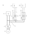
- FIG. 2 is a diagram for explaining the configuration of a power control system 100 according to the second embodiment.
- FC isolation converter 14 As illustrated, in the power control system 100 of the present embodiment, two SOFCs 10-1 and 10-2 are arranged. Further, the FC isolation converter 14 described in the first embodiment is individually connected to each of the two SOFCs 10-1 and 10-2. Hereinafter, the FC isolation converter 14 connected to the SOFC 10-1 is referred to as "FC isolation converter 14-1", and the FC isolation converter 14 connected to the SOFC 10-2 is referred to as "FC isolation converter 14-2". .
- the SOFC 10 with a small output voltage As described above, if the SOFC 10 with a small output voltage is configured, the electrical safety of the SOFC 10 is improved.
- the SOFC 10 having a small output voltage for example, in the case where the required power generation for the SOFC 10 is large, such as when the required charge amount of the high voltage battery 12 is relatively large, taking out from the SOFC 10 in order to secure the required power generation.
- the current needs to be increased. However, there is a limit to the magnitude of current that can be extracted from a single SOFC 10.
- the two SOFCs 10-1 and 10-2 are more preferable from the viewpoint of securing the required generated power even when the SOFC 10 having a small output voltage is disposed. Are arranged in parallel.
- the present inventors pay attention to such a situation, and individually connect the FC isolation converter 14-1 and the FC isolation converter 14-2 to each SOFC 10-1 and 10-2, respectively. It was conceived to control the extraction current according to each output characteristic of ⁇ 2. As a result, it is possible to carry out the extraction of the individual suitable current according to the output characteristics from any of the SOFCs 10-1 and 10-2.
- FC isolation converter 14-1 and the FC isolation converter 14-2 are individually connected to the respective SOFCs 10-1 and 10-2.
- the extraction current according to the required generated power can be realized more suitably.
- the extraction current can be set appropriately according to the output characteristics of each of the two SOFCs 10-1 and 10-2.
- the SOFC 10-1 and the FC isolation converter 14-1, and the SOFC 10-2 and the FC isolation converter 14-2 are configured as separate systems. Therefore, unlike the case where two SOFCs 10-1 and 10-2 are connected to one FC isolated converter 14, the SOFC 10-1 and the FC isolated converter 14-1, the SOFC 10-2 and the FC isolated converter 14-2, Can be appropriately distributed and laid out.
- the degree of freedom in the layout of the SOFCs 10-1 and 10-2 and the FC isolated converters 14-1 and 14-2 can be further improved.
- the low voltage line 20-1 connecting the SOFC 10-1 and the FC isolation converter 14-1, and the low voltage line 20 connecting the SOFC 10-2 and the FC isolation converter 14-2. -2 is configured with a separate wiring system. As a result, compared to the case where two SOFCs 10-1 and 10-2 are connected to one FC isolated converter 14 by one wiring system, the current conducted to each low voltage line 20-1 and 20-2 is reduced. It will be done.
- the wire diameters of the low voltage line 20-1 and the low voltage line 20-2 can be made smaller, so that bending deformation can be performed with a higher curvature. Therefore, the degree of freedom of the wiring layout is improved, which contributes to the further improvement of the degree of freedom of the layout of the SOFC 10 and the FC isolation converter 14.
- the FC isolation converter 14-1 and the FC isolation converter 14-2 are dispersedly configured for each of the two SOFCs 10-1 and 10-2 as in the present embodiment, the respective SOFCs 10-1 and 10
- the configuration of the circuit elements required for the output control of ⁇ 2 is also dispersed.
- the current conducted in the circuits of the FC isolation converter 14-1 and the FC isolation converter 14-2 is smaller than in the case where one FC isolation converter 14 is connected to the two SOFCs 10-1 and 10-2.
- each FC isolation converter 14-1 and FC isolation converter 14-2 can be configured with almost no increase in the total number of parts for the FC isolation converter 14 configured by one unit, and Can be smaller than the FC isolated converter 14 in the case of one unit.
- FC isolation converter 14-1 and the FC isolation converter 14-2 are individually connected to the SOFCs 10-1 and 10-2 as in this embodiment, the FC isolation converter 14-1 and the FC isolation are It is possible to suppress an increase in the overall size and cost of converter 14-2.
- FIG. 3 is a diagram for explaining the configuration of the power control system 100 in the present embodiment.
- the power control system 100 in the present embodiment has a low voltage side disposed in the low voltage line 20-1 between the SOFC 10-1 and the FC isolation converter 14-1.
- Low voltage side current sensor 30-2 and low voltage side voltage sensor disposed on low voltage line 20-2 between current sensor 30-1 and low voltage side voltage sensor 32-1, and SOFC 10-2 and FC insulating converter 14-2
- a high voltage side voltage sensor 34 disposed in the high voltage line 22 on the output side of the FC isolation converter 14-1 and the FC isolation converter 14-2 is provided.
- the low voltage side current sensor 30-1 detects the current of the low voltage line 20-1 (hereinafter, also simply referred to as “first low voltage side current Ilow1”) corresponding to the extraction current of the SOFC 10-1. Also, the low voltage side voltage sensor 32-1 detects a voltage corresponding to the output voltage of the SOFC 10-1 (the input voltage of the FC insulating converter 14-1) (hereinafter, also simply referred to as “first low voltage side voltage Vlow1"). Do.
- the low voltage side current sensor 30-2 detects the current of the low voltage line 20-2 (hereinafter, also simply referred to as "the second low voltage side current Ilow2”) corresponding to the extraction current of the SOFC 10-2. Further, low voltage side voltage sensor 32-2 detects a voltage corresponding to the output voltage of SOFC 10-2 (the input voltage of FC insulating converter 14-2) (hereinafter, also simply referred to as “second low voltage side voltage Vlow2”) Do.
- high voltage side voltage sensor 34 the voltage of high voltage line 22 which corresponds to the output voltage of FC insulation converter 14-1 and FC insulation converter 14-2 (below, also simply described as high voltage side voltage Vhigh) To detect.
- the power control system 100 includes a controller 90 as a transformer individual control unit that controls the FC isolation converter 14-1 and the FC isolation converter 14-2.
- the controller 90 is constituted by a computer, particularly a microcomputer, provided with a central processing unit (CPU), a read only memory (ROM), a random access memory (RAM), and an input / output interface (I / O interface).
- the controller 90 is programmed to be able to execute the process of this embodiment.
- the controller 90 may be configured as one device, or may be divided into a plurality of devices, and each control of the present embodiment may be configured to be distributed and processed by the plurality of devices.
- the controller 90 is a first low voltage detected by the low voltage side current sensor 30-1, the low voltage side voltage sensor 32-1, the low voltage side current sensor 30-2, and the low voltage side voltage sensor 32-2.
- the FC isolated converter 14-1 and the high-voltage voltage detection value Vhighd based on the low-voltage current detection value Ilow1d, the first low-voltage voltage detection value Vlow1d, the second low-voltage current detection value Ilow2d, the second low-voltage voltage detection value Vlow2d, and the high-voltage voltage detection value Vhighd
- the boost ratio is controlled by switching control of each of the FC isolated converters 14-2.
- control by the controller 90 will be described in more detail.
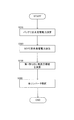
- FIG. 4 is a flowchart for explaining a control mode of the power control system 100 of the present embodiment.
- the steps shown in this flowchart are not necessarily limited to the order described below, and it is possible to replace the steps as much as possible.
- step S110 the controller 190 calculates the acceptable power (required charge power) of the high voltage battery 12 based on, for example, a detection value of a charge amount (SOC) sensor (not shown).
- SOC charge amount
- step S120 the controller 190 calculates the total required generated power of the SOFC 10-1 and the SOFC 10-2 from the calculated required charge power of the high voltage battery 12.
- step S130 the controller 90 calculates a first low-voltage current target value Ilow1t and a second low-voltage current target value Ilow2t. Specifically, the controller 90 sets the first low voltage so that the deviation between the acquired first low voltage side detected voltage Vlow1d and the second low voltage side detected voltage Vlow2d becomes equal to or smaller than the allowable value ⁇ V while satisfying the calculated required generated power. A side current target value Ilow1t and a second low voltage side current target value Ilow2t are calculated.
- the controller 90 suppresses the variation between the first low voltage side voltage Vlow1 (the voltage of the SOFC 10-1) and the second low voltage side voltage Vlow2 (the voltage of the SOFC 10-2) while satisfying the required charging power of the high voltage battery 12.
- the first low-voltage side current target value Ilow1t target current value for taking out SOFC 10-1
- the second low-voltage side current target value Ilow2t target value for taking-out current SOFC 10-2
- FIG. 5 is a diagram showing an outline of IV curves of two SOFC 10-1 and SOFC 10-2 having mutually different output characteristics.
- the IV curve of SOFC 10-1 is indicated by a solid line
- the IV curve of SOFC 10-2 is indicated by a broken line. That is, in this embodiment, it is assumed that the output characteristic of the SOFC 10-1 is higher than the output characteristic of the SOFC 10-2.
- the first low-voltage side current is a target value of the current drawn from each SOFC 10-1, 10-2.
- the target value Ilow1t and the second low-voltage side current target value Ilow2t are set according to the respective output characteristics.
- the controller 90 sets the value of the first low voltage side current Ilow1 indicated by the dotted line in FIG. 5 to the first low voltage side current target value Ilow1t
- the controller 90 makes the current corresponding to the first low voltage side current target value Ilow1t SOFC10- A region in which the second low-voltage-side detected voltage Vlow2d corresponding to the output voltage of the SOFC 10-2 falls within the range of the allowable value ⁇ V or less with respect to the first low-voltage-side detected voltage Vlow1d taken out of 1 (FIG. From the hatched region), the second low-voltage side current target value Ilow2t is selected in consideration of the total required generated power.
- the controller 90 sets the first low-voltage target current value Ilow1t and the second low-voltage current target calculated at step S130 to the first low-voltage current detection value Ilow1d and the second low-voltage current detection value Ilow2d, respectively.
- the boost ratio of each of the FC isolation converter 14-1 and the FC isolation converter 14-2 is controlled so as to approach the value Ilow2t.
- each FC isolation converter 14-1 and FC isolation converter 14 that can set a suitable extraction current according to the output characteristics of each of the two SOFCs 10-1 and 10-2. Switching control of -2 is realized.
- the power control system 100 of the present embodiment further includes a controller 90 that individually controls the FC isolation converter 14-1 and the FC isolation converter 14-2 connected to the SOFC 10-1 and the SOFC 10-2.
- the difference between the first low voltage side voltage Vlow1 and the second low voltage side voltage Vlow2 as the output voltage of each of the SOFC 10-1 and the SOFC 10-2 becomes equal to or less than a predetermined value (permissible value ⁇ V).
- the extraction current of each SOFC 10-1 and SOFC 10-2 is set (step S130 in FIG. 4).
- FIG. 6 is a diagram for explaining the configuration of the power control system 100 according to the present embodiment. 6 shows only the main configuration of the power control system 100 in order to simplify the drawing.
- the power converter of the power control system 100 of this embodiment is an auxiliary that boosts the output voltage of the FC isolation converter 14 at a predetermined boost ratio.
- a non-insulated boost converter 40 is provided as a booster.
- Non-insulated boost converter 40 is configured as a charge pump type boost converter capable of setting a boost ratio within a predetermined range by switching control. And, in the present embodiment, the non-insulated boost converter 40 is connected between the FC isolated converter 14 and the high voltage battery 12.
- the FC isolation converter 14 boosts the output voltage of the SOFC 10 in the low voltage line 20 at the basic boost ratio and outputs the boosted voltage to the medium voltage line 21.
- non-insulated boost converter 40 boosts the voltage of medium voltage line 21 at a predetermined boost ratio (hereinafter also referred to as “auxiliary boost ratio”) and outputs it to high voltage line 22.
- the output voltage of the SOFC 10 is supplied to the high voltage battery 12 after being boosted in two steps in the order of the FC isolated converter 14 and the non-insulated boost converter 40.
- the second stage non-insulated boost is performed while boosting the output voltage of the SOFC 10 with a relatively large basic boost ratio by the boost circuit (insulated transformer 14c) of the first stage FC isolation converter 14.
- the control of converter 40 can adjust the auxiliary boost ratio with high accuracy.
- the boost ratio (basic boost ratio ⁇ auxiliary boost ratio) to the output voltage of the SOFC 10 substantially by the FC isolated converter 14 and the non-insulated boost converter 40 is suitably set according to the required charge power of the high voltage battery 12 and the like. It becomes possible to adjust.
- the output voltage of the SOFC 10 is basically up to near a desired target voltage according to the required charge power of the high voltage battery 12 by the basic boost of the FC isolation converter 14. It is boosted.
- the non-insulated boost converter 40 can also preferably cope with the adjustment of the substantial boost ratio of the output voltage of the SOFC 10 in a relatively short time.
- the power converter in the power control system 100 of the present embodiment further includes a non-insulated boost converter 40 as an auxiliary boost unit that boosts the output voltage of the SOFC 10 at a predetermined boost ratio.
- the non-insulation type boost converter 40 relatively quickly The adjustment of the substantial boost ratio of the output voltage of the SOFC 10 during the period can be suitably coped with.
- the fifth embodiment will be described below.
- the same components as those in the first to fourth embodiments are denoted by the same reference numerals, and the detailed description thereof will be omitted.
- an example of power control based on the configuration of the power control system 100 described in the fourth embodiment will be described.
- FIG. 7 is a diagram for explaining the configuration of the power control system 100 in the present embodiment.
- the power control system 100 in the present embodiment includes the low voltage side current sensor 30 and the low voltage side voltage sensor 32 disposed in the low voltage line 20, and the middle voltage line 21.
- the medium voltage side current sensor 50 and the medium voltage side voltage sensor 52 disposed in the high voltage side voltage sensor 34 are disposed in the high voltage line 22.
- the low voltage side current sensor 30 detects a low voltage side current Ilow corresponding to the output current of the SOFC 10. Further, the low voltage side voltage sensor 32 detects a low voltage side voltage Vlow which is a voltage of the low voltage line 20.
- medium voltage side current sensor 50 detects medium voltage side current Imed corresponding to an input current from FC isolated converter 14 to non-insulated boost converter 40. Further, the middle voltage side voltage sensor 52 detects a middle voltage side voltage Vmed which is a voltage of the middle voltage line 21.
- high voltage side voltage sensor 34 detects high voltage side voltage Vhigh which is the voltage of high voltage line 22 (corresponding to the voltage of high voltage battery 12).
- the power control system 100 includes a controller 190 that controls the FC isolation converter 14 and the non-insulation boost converter 40.
- the controller 190 is constituted by a computer, particularly a microcomputer, provided with a central processing unit (CPU), a read only memory (ROM), a random access memory (RAM), and an input / output interface (I / O interface).
- the controller 90 is programmed to be able to execute the process of this embodiment.
- the controller 190 may be configured as one device, or may be divided into a plurality of devices and configured to perform distributed processing of each control of the present embodiment with the plurality of devices.
- the controller 190 detects the low voltage side current detected by the low voltage side current sensor 30, the low voltage side voltage sensor 32, the medium voltage side current sensor 50, the medium voltage side voltage sensor 52, and the high voltage side voltage sensor 34.
- Control FC isolated converter 14 and non-insulated boost converter 40 based on detected value Ilowd, low voltage side detected voltage Vlowd, middle voltage side current detected value Imedd, middle voltage side voltage detected value Vmedd, and high voltage side detected voltage Vhighd Do.
- control by the controller 190 in the present embodiment will be described in more detail.
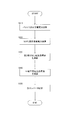
- FIG. 8 is a flowchart for explaining a control mode of the power control system 100 of the present embodiment.
- the steps shown in this flowchart are not necessarily limited to the order described below, and it is possible to replace the steps as much as possible.
- step S210 the controller 190 receives the high voltage battery 12 based on, for example, the detected charge value (or estimated value) of the high voltage battery 12 detected by a charge amount (SOC) sensor (not shown). Calculate the available power (requested charge power).
- SOC charge amount
- step S220 the controller 190 calculates the required generated power for the SOFC 10 from the calculated required charged power of the high voltage battery 12.
- step S230 the controller 190 calculates the extraction current correction target value (hereinafter also referred to as "first extraction current target value”) of the SOFC 10 based on the calculated required power generation and the low voltage side voltage detection value Vlowd. That is, the first extraction current target value is calculated from the viewpoint of limiting the voltage of the low voltage line 20 (low voltage side voltage Vlow) so as not to exceed a certain upper limit while satisfying the requirement for charging power of the high voltage battery 12 Target value of the SOFC 10 extraction current (low-voltage side current Ilow).
- first extraction current target value is calculated from the viewpoint of limiting the voltage of the low voltage line 20 (low voltage side voltage Vlow) so as not to exceed a certain upper limit while satisfying the requirement for charging power of the high voltage battery 12 Target value of the SOFC 10 extraction current (low-voltage side current Ilow).
- the controller 190 first calculates the basic extraction current target value of the SOFC 10 based on the calculated required power generation. Then, based on the output characteristic (IV characteristic) of the SOFC 10, a value obtained by correcting the basic extraction current target value so that the low voltage side voltage detection value Vlowd is less than a predetermined upper limit voltage Vlim (for example 60V) is a first extraction current target value Set as.
- a predetermined upper limit voltage Vlim for example 60V
- the first extracted current target value is a target value calculated from the viewpoint of limiting the low voltage side voltage detection value Vlowd while satisfying the required generated power
- a basic determined based on the original first extracted current target value It will be set to the value more than the take-out current target value.
- step S240 the controller 190 controls the FC isolated converter 14 and the non-insulated boost converter 40 based on the first takeout current target value and the high voltage side detected voltage value Vhighd calculated in step S230.
- the controller 190 performs switching control of the FC isolated converter 14 and the non-insulated boost converter 40 so that the low voltage side current detection value Ilowd approaches the first extraction current target value, and the total boost ratio (basic boost ratio Adjust the ratio + auxiliary boost ratio).
- one aspect of control of each converter capable of charging high voltage battery 12 with desired power can be provided while maintaining low voltage side voltage Vlow below upper limit voltage Vlim.
- the non-insulated boost converter 40 is disposed between the FC isolated converter 14 and the high voltage battery 12. That is, a system is provided which can supply the high voltage battery 12 while boosting the output voltage of the SOFC 10 in two steps in the order of the FC isolation converter 14 and the non-insulation boost converter 40.
- the controller 190 is further provided as a boost control unit that controls the FC isolated converter 14 and the non-isolated boost converter 40.
- the controller 190 also controls the boost ratio of the non-insulated boost converter 40 based on at least the output voltage of the SOFC 10 (low voltage Vlow) and the voltage of the high voltage battery 12 (high voltage Vhigh).
- the two steps of boosting of the output voltage of SOFC 10 by FC isolated converter 14 and non-insulated boost converter 40 are suitably executed by control of non-insulated boost converter 40. be able to.
- controller 190 of the present embodiment limits the low voltage side voltage Vlow corresponding to the output voltage of the SOFC 10 to less than a predetermined value (upper limit voltage Vlim) (step S230 in FIG. 8).
- the low voltage line 20 and the medium voltage line 21 are electrically isolated by the isolation transformer 14 c of the FC isolation converter 14. Therefore, when low voltage side voltage Vlow which is the voltage of low voltage line 20 is maintained below upper limit voltage Vlim, the operating voltage of low voltage line 20 on the input side of FC isolation converter 14 and SOFC 10 is substantially lower than upper limit voltage Vlim. It can be done. That is, the electrical safety of the low voltage line 20 and the SOFC 10 can be further improved.
- the low voltage line 20 and the SOFC 10 substantially have operating voltages less than 60 V. Since they can be set in parts, they can be removed from the high voltage safety requirement parts described above.
- the layout freedom of the low voltage line 20 and the SOFC 10 on the vehicle can be improved.
- the SOFC 10 may be configured such that the substantial maximum output voltage of the SOFC 10 is less than 60V.
- the low voltage system components including the SOFC 10 and the low voltage line 20 can be maintained at less than 60 V more reliably, in combination with the control in which the low voltage side voltage Vlow is maintained at less than 60 V as described above. Electrical safety can be further enhanced.
- FIG. 9 is a diagram for explaining the configuration of the power control system 100 according to the present embodiment. Note that FIG. 9 shows only the main configuration of the power control system 100 in order to simplify the drawing.
- the arrangement positions of the non-insulated boost converter 40 and the FC isolated converter 14 are interchanged in the present embodiment. That is, in the power control system 100 of the present embodiment, the non-insulated boost converter 40 is disposed between the SOFC 10 and the FC isolated converter 14.
- the other configuration is the same as that of the power control system 100 according to the fourth embodiment.
- the non-insulated boost converter 40 boosts the output voltage of the SOFC 10 in the low voltage line 20 and outputs the boosted voltage to the medium voltage line 21.
- the FC isolation converter 14 boosts the voltage of the medium voltage line 21 and outputs the boosted voltage to the high voltage line 22. That is, in this embodiment, the output voltage of the SOFC 10 is supplied to the high voltage battery 12 after being boosted in two steps in the order of the non-insulated boost converter 40 and the FC isolated converter 14.
- the output voltage of the SOFC 10 is adjusted in accordance with the control of the first stage non-insulated boost converter 40 according to the requirement of the high voltage battery 12 while the auxiliary boost ratio is adjusted.
- the voltage of the medium voltage line 21 boosted by the boost converter 40 is further boosted by the second stage FC isolation converter 14 to appropriately adjust the output voltage from the FC isolation converter 14 to the high voltage line 22. it can.
- the total boost ratio in the two-stage boost of non-insulated boost converter 40 and FC isolated converter 14 according to the fluctuation of the required power of high voltage battery 12
- the auxiliary boost ratio ⁇ the basic boost ratio can be suitably adjusted by switching control for the non-insulated boost converter 40 with high responsiveness.
- the non-insulated boost converter 40 as an auxiliary boost is disposed between the SOFC 10 and the FC isolated converter 14.
- the output voltage of the SOFC 10 can be suitably adjusted by the two-stage boost control by the non-insulated boost converter 40 and the FC isolated converter 14 in accordance with the required charge power of the high voltage battery 12.
- the SOFC 10 is disposed on the input side of the non-insulated boost converter 40. Therefore, depending on the output power of the SOFC 10, the SOFC 10 to the non-insulated boost It is assumed that the current input to converter 40 is relatively large.
- the circuit of the non-insulated boost converter 40 is configured as a non-insulated converter in which the isolation transformer 14c is not used.
- the increase in size of the die boost converter 40 is suppressed.
- the non-insulated boost converter 40 is mainly composed of circuit elements such as an inductor or a capacitor, the size increase of these circuit elements is limited compared to the FC isolated converter 14 even if the input current increases. Can be Therefore, by arranging the non-insulated boost converter 40 between the SOFC 10 and the FC isolated converter 14 as in the present embodiment, it is possible to include the non-insulated boost converter 40 and to suppress an increase in the overall size of the system.
- the degree of system size increase with respect to the increase in input current to the non-insulated boost converter 40 due to the large output. Therefore, the SOFC 10 with a larger output can be adopted while suppressing an increase in size of the system.
- the seventh embodiment will be described below.
- the same components as those in the first to sixth embodiments are denoted by the same reference numerals, and the detailed description thereof will be omitted.
- an example of power control based on the configuration of the power control system 100 described in the sixth embodiment will be described.
- FIG. 10 is a diagram for explaining the configuration of the power control system 100 in the present embodiment.
- the power control system 100 in the present embodiment includes the low voltage side current sensor 30 and the low voltage side voltage sensor 32, and the middle voltage side current as in the fifth embodiment.
- the sensor 50, the medium voltage side voltage sensor 52, and the high voltage side voltage sensor 34 are disposed.
- the low voltage side current Ilow detected by the low voltage side current sensor 30 of the present embodiment corresponds to the input current from the SOFC 10 to the non-insulated boost converter 40.
- the middle voltage side current Imed detected by the middle voltage side current sensor 50 of the present embodiment corresponds to the input current from the non-insulated boost converter 40 to the FC isolated converter 14.
- power control system 100 detects the low voltage side current detected by low voltage current sensor 30, low voltage sensor 32, medium voltage current sensor 50, medium voltage sensor 52, and high voltage sensor 34, respectively.
- a non-insulated boost converter 40 and an FC isolated converter 14 are controlled based on Ilowd, low voltage side voltage detection value Vlowd, middle voltage side current detection value Imedd, middle voltage side voltage detection value Vmedd, and high voltage side voltage detection value Vhighd
- a controller 190 having a hardware configuration similar to that of the fifth embodiment is provided. Hereinafter, control by the controller 190 in the present embodiment will be described in more detail.
- FIG. 11 is a flowchart for explaining a control mode of the power control system 100 of the present embodiment.
- the steps shown in this flowchart are not necessarily limited to the order described below, and it is possible to replace the steps as much as possible.
- step S210 the controller 190 calculates the required charge power of the high voltage battery 12 based on the charge amount detection value (or the estimated value) of the high voltage battery 12, as in the fifth embodiment. .
- step S320 the controller 190 calculates the required generated power for the SOFC 10 from the calculated required charged power of the high voltage battery 12.
- step S330 the controller 190 sets the SOFC 10 extraction current correction target value (hereinafter also referred to as "second extraction current target value") based on the calculated required power generation and the low voltage side voltage detection value Vlowd, and the medium voltage side. Calculate the current target value.
- second extraction current target value the SOFC 10 extraction current correction target value
- the controller 190 calculates the second extracted current target value by the same calculation as the calculation of the first extracted current target value described in the fifth embodiment.
- step S340 the controller 190 calculates the medium voltage side current target value based on the low voltage side voltage detection value Vlowd, the medium voltage side voltage detection value Vmedd, and the calculated second extraction current target value.
- the middle voltage side current target value is calculated from the viewpoint of limiting so that the voltage of the middle voltage line 21 (middle voltage side voltage Vmed) does not exceed a certain upper limit value.
- Target value of the converter 40 is calculated from the viewpoint of limiting so that the voltage of the middle voltage line 21 (middle voltage side voltage Vmed) does not exceed a certain upper limit value.
- the controller 190 calculates the supplied electric power P by multiplying the low voltage voltage detection value Vlowd by the calculated second extracted current target value. Then, the controller 190 calculates the basic middle voltage side current target value based on the calculated supplied power P. Furthermore, the controller 190 sets a value obtained by correcting the basic medium voltage side current target value such that the medium voltage side voltage detection value Vmedd is less than the upper limit voltage Vlim as a medium voltage side voltage target value.
- step S350 the controller 190 controls the non-insulated boost converter 40 and the FC isolated converter 14 based on the calculated second extracted current target value and the medium voltage side current target value.
- controller 190 causes non-insulated boost converter 40 and low-voltage side current detection value Ilowd and medium-voltage side voltage detection value Vmedd to approach the first output current target value and the medium-voltage side current target value, respectively.
- the switching control of the FC isolation converter 14 is performed to adjust the total boost ratio (basic boost ratio + auxiliary boost ratio).
- the low voltage side voltage Vlow and the medium voltage side voltage Vmed are both controlled to be lower than the upper limit voltage Vlim by the above-described steps, in particular, the processes of steps S330 to S350.
- the power control system 100 of the present embodiment further includes a controller 190 as a boost control unit that controls the non-insulated boost converter 40 and the FC isolated converter 14.
- the controller 190 also controls the boost ratio of the non-insulated boost converter 40 based on at least the output voltage of the SOFC 10 (low voltage Vlow) and the voltage of the high voltage battery 12 (high voltage Vhigh).
- the two steps of boosting of the output voltage of SOFC 10 by non-insulated boost converter 40 and FC isolated converter 14 are suitably performed by control of non-insulated boost converter 40. can do.
- the controller 190 limits the low voltage side voltage Vlow corresponding to the output voltage of the SOFC 10 and the medium voltage voltage Vmed corresponding to the output voltage of the non-insulated boost converter 40 to less than a predetermined value (upper limit voltage Vlim). (Steps S330 to S350 in FIG. 11).
- the middle voltage line 21 and the high voltage line 22 are electrically isolated by the isolation transformer 14 c of the FC isolation converter 14. Therefore, when both low voltage side voltage Vlow and middle voltage side voltage Vmed are maintained below upper limit voltage Vlim, the operating voltages of medium voltage line 21, non-insulated boost converter 40, low voltage line 20 and SOFC 10 are substantially reduced. It can be less than the upper limit voltage Vlim. That is, the electrical safety of each of these parts can be further improved.
- the upper limit voltage Vlim is set to a value less than 60 V
- the medium voltage line 21, the non-insulation boost converter 40, and the low voltage line 20 can be substantially set to components whose operating voltage is less than 60 V, so that they can be removed from the high voltage safety requirement components described above.
- the power control system 100 when the power control system 100 according to the present embodiment is mounted on a vehicle, the vehicle of the medium voltage line 21, the non-insulated boost converter 40, the low voltage line 20, and the SOFC 10 of more types of components
- the upper layout freedom can be improved.
- the SOFC 10 may be configured such that the substantial maximum output voltage of the SOFC 10 is less than 60V.
- the low voltage side voltage Vlow and the medium voltage side voltage Vmed include the SOFC 10, the low voltage system component including the low voltage line 20, and the medium voltage line 21 more reliably in combination with the control maintained at less than 60V.
- the medium voltage system parts can be maintained at less than 60 V, the electrical safety of these parts can be further enhanced.
- each above-mentioned embodiment showed only a part of application example of the present invention, and limited the technical scope of the present invention to the concrete composition of each above-mentioned embodiment. It is not the purpose to do.
- control modes of the FC isolated converter 14 or the non-insulated boost converter 40 described in the third embodiment, the fifth embodiment, and the seventh embodiment are all examples, and various modifications are possible. That is, in the control of the FC isolation converters 14-1 and 14-2 of the third embodiment, if it is possible to adjust each output current according to the output characteristics of each SOFC 10-1 and 10-2. Instead of or in addition to the parameters such as the high voltage side voltage Vhigh used for controlling the FC isolation converters 14-1 and 14-2, arbitrary parameters may be used as appropriate.
- the high voltage battery 12 is supplied with power according to the required charging power while the low voltage If it is possible to control Vlow or the low voltage side voltage Vlow and the medium voltage side voltage Vmed to less than the upper limit voltage Vlim, instead of the parameters used in the control of the fifth embodiment and the seventh embodiment, Alternatively, arbitrary parameters may be used as appropriate.
- FC isolation converter 14 energy equivalent to the power to be supplied to the high voltage battery 12 is input to output while maintaining substantial electrical isolation between the input and output.
- n (n ⁇ 3) SOFCs 10 may be disposed, and n FC isolated converters 14 may be individually connected to the n SOFCs 10. Thereby, the extraction current may be individually controlled according to the output characteristics of the n SOFCs 10.
- the configurations of the second to fourth embodiments and the configurations of the fifth to seventh embodiments may be arbitrarily combined.
- the non-insulated boost converter 40 is used. May be provided.
- the SOFC 10-1 (10-2) and the FC isolation converter 14-1 (14-2) or the FC isolation converter 14-1 (14 A non-insulated boost converter 40-1 (40-2) is provided between the high-voltage battery 12 and the FC isolated converter 14-1 (14-2) and the non-insulated boost converter 40-1 (40-).
- the control described in the fifth and seventh embodiments may be executed with respect to 2).
- the insulation transformer 14c of the FC insulation converter 14 may be used only for the electrical insulation function so that boosting by the number of turns is not performed. That is, after setting the step-up ratio by the insulating transformer 14c to 1: 1 by equalizing the number of turns of the primary coil and the number of turns of the secondary coil of the insulating transformer 14c, elements other than the insulating transformer 14c in the FC insulating converter 14
- the output voltage of the SOFC 10 may be boosted by the non-insulation type boost converter 40 and the non-insulation type boost converter 40.
- the power control system 100 includes an external load driven by any vehicle or other power provided with an external load (motor) that receives and drives the supply of power such as a railway vehicle other than a car. It can apply to the apparatus equipped.
Landscapes
- Engineering & Computer Science (AREA)
- Power Engineering (AREA)
- Life Sciences & Earth Sciences (AREA)
- Sustainable Energy (AREA)
- Sustainable Development (AREA)
- Transportation (AREA)
- Mechanical Engineering (AREA)
- Chemical & Material Sciences (AREA)
- Electrochemistry (AREA)
- General Chemical & Material Sciences (AREA)
- Chemical Kinetics & Catalysis (AREA)
- Manufacturing & Machinery (AREA)
- Materials Engineering (AREA)
- Microelectronics & Electronic Packaging (AREA)
- Fuel Cell (AREA)
- Electric Propulsion And Braking For Vehicles (AREA)
- Charge And Discharge Circuits For Batteries Or The Like (AREA)
- Dc-Dc Converters (AREA)
Abstract
低電圧の電力を生成する電力生成装置と、電力生成装置により生成される電力で充電される高電圧バッテリと、高電圧バッテリから電力の供給を受ける外部負荷と、電力生成装置と高電圧バッテリの間に接続された電力変換器と、を備え、電力変換器が、絶縁型電力変換器を含む電力制御システム。
Description
この発明は、電力制御システムに関する。
燃料電池や内燃機関等の電力生成装置で生成された電力を制御しつつ、モータ等の外部負荷への供給及びバッテリへの充電を行う電力制御システムが知られている。このような電力制御システムにおいては、負荷の要求又はバッテリの要求充電量などに応じて電力生成装置からの出力電圧をDCDCコンバータ等の電力変換器で調節している。
例えば、JP4616247Bには、電力生成装置としての燃料電池スタックと外部負荷及び電力貯蔵装置との間にDCDCコンバータを配置し、DCDCコンバータによって電力貯蔵装置の要求に応じて燃料電池スタックからパルス電流を取り出すシステムが提案されている。
しかしながら、従来の電力制御システムでは、電力生成装置の出力電圧よりもバッテリ電圧が定常的に高いシステムについては想定されていなかった。
本発明は、このような事情に鑑みてなされたものであり、その目的は、電力生成装置の出力電圧よりも高電圧のバッテリを有する好適な電力制御システムを提供することにある。
本発明のある態様によれば、低電圧の電力を生成する電力生成装置と、電力生成装置により生成される電力で充電される高電圧バッテリと、高電圧バッテリから電力の供給を受ける外部負荷と、電力生成装置と高電圧バッテリの間に接続された電力変換器と、を備える電力制御システムが提供される。そして、電力制御システムにおいて、電力変換器は絶縁型電力変換器を含む。
以下、添付図面を参照しながら本発明の実施形態について説明する。
(第1実施形態)
図1は、第1実施形態にかかる電力制御システム100の概略構成を説明する図である。
図1は、第1実施形態にかかる電力制御システム100の概略構成を説明する図である。
図示のように、電力制御システム100は、電力生成装置としてのSOFC(固体酸化物形燃料電池:solid oxide fuel cell)10と、SOFC10が生成(発電)する電力で充電される高電圧バッテリ12と、SOFC10と高電圧バッテリ12の間に配置された電力変換器としてのFC絶縁コンバータ14と、高電圧バッテリ12から供給される電力で駆動する外部負荷としての走行モータ16と、を有している。
SOFC10は、セラミック等の固体酸化物で形成された電解質層を、アノード(燃料極)とカソード(空気極)により挟み込んで得られるセルを積層してなるSOFCスタックとして構成される。SOFC10は、燃料極に燃料ガス(水素)の供給を受けるとともに、空気極に酸化ガス(酸素)の供給を受けることで発電する。
本実施形態におけるSOFC10は、例えば高電圧バッテリ12の充電電力が要求に対して不足している場合などに、FC絶縁コンバータ14により要求電力に応じた所定の電流の出力(発電)が行われる。
なお、SOFC10を構成する各単位セルは、1.0V程度の出力電圧となる。したがって、単位セルの積層数を適宜調整することで、SOFC10の出力電圧を任意に調節することができる。例えば、SOFC10の最大出力電圧が60V~200Vの範囲となるように、単位セルの積層数を設定することができる。
しかしながら、本実施形態では、より安全性を高める観点からSOFC10の電圧をできるだけ低くするように、単位セルの積層数を調節する。特に、SOFC10の最大出力電圧が60V未満となるように、単位セルの積層数を調節する。なお、SOFC10は、さらに燃料系補機及び空気系補機を含む燃料電池システムとして構成されていても良い。
高電圧バッテリ12は、例えば、リチウムイオンバッテリー等の二次電池で構成される。また、高電圧バッテリ12は、FC絶縁コンバータ14により調整されたSOFC10の発電電力によって充電される。また、高電圧バッテリ12は、走行モータ16からの電力要求に基づき、走行モータ16に適宜電力を供給する。
FC絶縁コンバータ14は、SOFC10の発電電力を高電圧バッテリ12に充電すべく、SOFC10の出力電圧を調節する絶縁型のDCDCコンバータにより構成される。FC絶縁コンバータ14は、SOFC10側の低電圧ライン20に接続する低圧側スイッチング部14aと、高電圧バッテリ12及び走行モータ16に結線される高電圧ライン22に接続する高圧側スイッチング部14bと、低圧側スイッチング部14aと高圧側スイッチング部14bの間を接続する絶縁トランス14cを有する。
そして、絶縁トランス14cは、入力側の低電圧ライン20の電圧を所定の昇圧比で昇圧して高電圧ライン22に出力できるように、当該昇圧比に対応する巻数比が設定されている。以下では、絶縁トランス14cの巻数比に応じて定まる昇圧比を「基本昇圧比」とも称する。
さらに、図1には示していないが、FC絶縁コンバータ14は、絶縁トランス14cの巻数比に応じた基本昇圧比を微調整するためのコンデンサ又はリアクトル等で構成される共振回路を含んでいる。
上記構成により、本実施形態の電力制御システム100では、FC絶縁コンバータ14の低圧側スイッチング部14a又は高圧側スイッチング部14bに対して所定のスイッチング制御を行うによって、高電圧バッテリ12に充電要求に応じて当該高電圧バッテリ12にSOFC10の発電電力を供給することができるように、SOFC10の出力電圧(低電圧ライン20の電圧)を調節することができる。
そして、特に、FC絶縁コンバータ14が絶縁トランス14cを有していることで、当該FC絶縁コンバータ14を挟んだ低電圧ライン20(SOFC12側)と高電圧ライン22(高電圧バッテリ12側)を電気的に絶縁しつつも、SOFC10から高電圧バッテリ12への電力供給が可能となっている。
一方、走行モータ16は、三相交流モータで構成されている。走行モータ16は、高電圧バッテリ12から供給される電力によって駆動される。また、走行モータ16には、高電圧バッテリ12から供給される直流電力を交流電力に変換するモータインバータ16aが設けられている。
なお、電力制御システム100には、必要に応じて、SOFC10の停止中などにおいて、高電圧バッテリ12とSOFC10の接続を物理的に遮断するためのリレーを、低電圧ライン20などに設けても良い。
上記構成の電力制御システム100によれば、FC絶縁コンバータ14により、高電圧側の高電圧バッテリ12及び走行モータ16と、低電圧側のSOFC10を電気的に絶縁しつつ、SOFC10の発電電力を高電圧バッテリ12に充電することができる。
以上説明した第1実施形態にかかる電力制御システム100によれば、以下の作用効果を奏する。
本実施形態の電力制御システム100は、低電圧の電力を生成する電力生成装置としてのSOFC10と、高電圧バッテリ12から電力の供給を受ける外部負荷としての走行モータ16と、SOFC10により生成される電力で充電される高電圧バッテリ12と、SOFC10と高電圧バッテリ12の間に接続された電力変換器と、を備える。そして、電力変換器は、絶縁型電力変換器としてのFC絶縁コンバータ14を含む。なお、本実施形態においてSOFC10が生成する「低電圧の電力」とは、SOFC10の出力電圧が高電圧バッテリ12の動作電圧と比べて低い電圧であることを意味する。
このように、高電圧の高電圧バッテリ12と、低電圧のSOFC10の間にこれらを電気的に絶縁する絶縁型電力変換器としてのFC絶縁コンバータ14が配置されたことで、電気的な安全性を保ちつつ、SOFC10の出力電圧を低く設定することができる。すなわち、FC絶縁コンバータ14によって、高電圧バッテリ12からSOFC10への電流の流れる抑制することができるので、SOFC10の出力電圧を低くしても、当該SOFC10の電気的な安全性を確保することができる。
なお、本実施形態の電力制御システム100においては、高電圧系の高電圧バッテリ12に高電圧ライン22を介して走行モータ16が接続されており、高電圧バッテリ12から走行モータ16への電力供給が可能となっている。
これにより、上述のように電気的な安全性を向上させたSOFC10の発電電力で高電圧バッテリ12に充電しつつ、高電圧バッテリ12に充電された電力を走行モータ16に供給するいわゆるシリーズ方式のハイブリッドシステムを構成することができる。
さらに、本実施形態の電力制御システム100は、車両(特に自動車)に搭載されており、外部負荷が走行モータ16として構成されている。すなわち、本実施形態の電力制御システム100を、一定の電気的安全性が要求される移動体としての車両に用いることで、電気的な安全性を向上させたSOFC10によるメリットをより好適に享受することができる。
また、FC絶縁コンバータ14は、SOFC10から高電圧バッテリ12に供給される電力を所定の昇圧比で昇圧する昇圧回路としての低圧側スイッチング部14a、高圧側スイッチング部14b、及び絶縁トランス14cを有する。
これにより、SOFC10の出力電圧をより好適に昇圧して高電圧バッテリ12を充電することができる。すなわち、上述のようにSOFC10の出力電圧をより低く構成すると、SOFC10と高電圧バッテリ12の間の電圧差が大きくなる。これに対して、本実施形態のFC絶縁コンバータ14の昇圧回路によって、SOFC10の出力電圧を高電圧バッテリ12への充電のために適切な電圧により好適に調整することができる。結果として、高電圧バッテリ12の電圧に対してより小さい出力電圧のSOFC10を構成することができる。
特に、本実施形態の電力制御システム100では、FC絶縁コンバータ14の昇圧回路は、絶縁トランス14cを含んでいる。
これにより、絶縁トランス14cによって上述したSOFC10と高電圧バッテリ12との間の電気的絶縁を確保しつつも、当該絶縁トランス14cの一次側コイル(SOFC10側)と二次側コイル(高電圧バッテリ12側)の間の巻数比を適宜設定することで、SOFC10の出力電圧の昇圧比を好適に設定することができる。すなわち、絶縁トランス14cを設けるという簡易な構成で、SOFC10と高電圧バッテリ12の電気的絶縁及び昇圧回路としての機能の双方を実現することができる。
以上、説明した第1実施形態の電力制御システム100においては、種々の変更が可能である。例えば、SOFC10の出力電圧を電力制御システム100が搭載される装置の要求等に応じて適宜設定することが可能である。
例えば、SOFC10は、電力制御システム100が搭載される装置(自動車及び鉄道車両等)において所定の安全要求が課される高電圧安全要求対象部品と判断される基準となる所定電圧未満の最大出力電圧をとるように構成されても良い。
すなわち、電力制御システム100が搭載される装置によっては、人体等に対する電気的安全性を確保する観点から、当該装置内における配置位置や所定の絶縁処理を施す等のより厳しい安全対策が要求される高電圧安全要求対象部品が法規等によって定められている場合がある。そして、ある部品がこのような高電圧安全要求対象部品であるか否かの判断は、通常、当該部品の動作電圧の大きさを基準として行われる。
このような事情に鑑みて、電力制御システム100が搭載される装置に応じて高電圧安全要求対象部品であると判断される基準となる電圧を上記所定電圧とすることで、SOFC10の最大出力電圧を高電圧安全要求対象部品と判断される電圧未満とすることができる。
これにより、SOFC10を電力制御システム100が搭載される装置の電気的安全性の観点から定められる高電圧安全要求対象部品から外すことができる。
特に、SOFC10は、最大出力電圧が60V未満となるように構成されても良い。このようにSOFC10の最大出力電圧を設定することで、本実施形態の電力制御システム100が特に自動車に搭載される場合において、当該SOFC10をより確実に高電圧安全要求対象部品から外すことができる。
ここで、自動車においては、衝突時に比較的大きく損傷することが想定される車両の前方領域や後方領域(以下、単に「衝突領域」とも記載する)においては、安全上の観点から高電圧安全要求対象部品を設置しないことが要求されている。そして、高電圧安全要求対象部品と判断される基準となる電圧は、概ね60Vと定められている。
このような状況に対して、SOFC10をその最大出力電圧が60V未満となるように構成して高電圧安全要求対象部品の対象から外していることで、高電圧安全要求対象部品であれば設置が想定されない車両の前方領域や後方領域においてもSOFC10を設置することができる。
さらに、このようにSOFC10の最大出力電圧を60V未満としても、SOFC10を高電圧バッテリ12等の高電圧系統と直接電気的に接続させると、高電圧バッテリ12とともにSOFC10が高電圧安全要求対象部品に該当することとなる。
しかしながら、本実施形態の電力制御システム100では、既に説明したように、FC絶縁コンバータ14によって、SOFC10と高電圧バッテリ12及び走行モータ16の間が相互に電気的に絶縁されている。これにより、SOFC10が高電圧バッテリ12を含む高電圧系統から独立した部品とすることができる。したがって、FC絶縁コンバータ14によりSOFC10をより確実に高電圧安全要求対象部品から外すことができる。結果として、SOFC10を、自動車の衝突領域を含めた任意の領域に設置することができるので、車両レイアウトの自由度を向上させることができる。
(第2実施形態)
以下、第2実施形態について説明する。なお、第1実施形態と同様の要素には同一の符号を付し、その詳細な説明は省略する。
以下、第2実施形態について説明する。なお、第1実施形態と同様の要素には同一の符号を付し、その詳細な説明は省略する。
図2は、第2実施形態における電力制御システム100の構成を説明する図である。
図示のように、本実施形態の電力制御システム100は、2つのSOFC10-1,10-2が配置されている。また、2つのSOFC10-1,10-2のそれぞれに、第1実施形態で説明したFC絶縁コンバータ14が個別に接続されている。なお、以下では、SOFC10-1に接続されたFC絶縁コンバータ14を「FC絶縁コンバータ14-1」と称し、SOFC10-2に接続されたFC絶縁コンバータ14を「FC絶縁コンバータ14-2」と称する。
ここで、本実施形態において、2つのSOFC10-1,10-2を配置した背景の一つについて説明する。しかしながら、以下で説明する背景は本実施形態の構成を限定するものではない。
既に説明したように、出力電圧の小さいSOFC10を構成すれば、当該SOFC10の電気的安全性が向上することとなる。一方で、出力電圧の小さいSOFC10の場合、例えば高電圧バッテリ12の要求充電量が比較的大きい場合等のSOFC10に対する要求発電電力が大きい場合においては、当該要求発電電力を確保すべくSOFC10からの取り出し電流を増大させる必要がある。しかしながら、単体のSOFC10から取り出すことのできる電流の大きさには限度がある。
これに対して、本実施形態の電力制御システム100では、出力電圧の小さいSOFC10を配置した場合であっても、より好適に要求発電電力を確保する観点から、2つのSOFC10-1,10-2を並列に配置している。
さらに、2つのSOFC10-1,10-2を並列に配置する場合においても、一台のFC絶縁コンバータ14によって2つのSOFC10-1,10-2からの取り出し電流をまとめて制御することが可能である。しかしながら、2つのSOFC10-1,10-2の個体差などの要因でこれらの出力特性(IV特性)がばらつくことが想定される。
このように出力特性がばらついた2つのSOFC10-1,10-2において、各SOFC10-1,10-2から同一の取り出し電流を取り出すと、それぞれの電圧の低下度合が異なるため、SOFC10-1,10-2の間の電圧がばらつくこととなる。特に、取り出し電流が大きくなると、出力特性の相違による電圧のばらつきが大きくなる(図5参照)。
したがって、一台のFC絶縁コンバータ14によって2つのSOFC10-1,10-2からの取り出し電流をまとめて制御する場合には、これらの内のより低い方の特性に合わせて電流の取り出しを行う必要がある。すなわち、2つのSOFC10-1,10-2の内の出力特性が低い方がボトルネックとなって、出力特性が高い方のパフォーマンスを十分に引き出せないという状況が想定される。
本発明者らは、このような状況に着目して、各SOFC10-1,10-2に個別にFC絶縁コンバータ14-1及びFC絶縁コンバータ14-2を接続することで、SOFC10-1,10-2のそれぞれの出力特性に応じた取り出し電流の制御を行うことに想到した。これにより、いずれのSOFC10-1,10-2からも出力特性に応じた個別の好適な電流の取り出しを実行することができる。
以上説明した第2実施形態にかかる電力制御システム100によれば、以下の作用効果を奏する。
本実施形態の電力制御システム100では、SOFC10を2つ備え、それぞれのSOFC10-1,10-2にFC絶縁コンバータ14-1及びFC絶縁コンバータ14-2が個別に接続される。
これにより、一つのSOFC10を設ける場合と比較して、要求発電電力に応じた取り出し電流をより好適に実現することができる。その上で、2つのSOFC10-1,10-2のそれぞれの出力特性に応じて好適に取り出し電流を設定することができる。
さらに、本実施形態では、SOFC10-1及びFC絶縁コンバータ14-1と、SOFC10-2及びFC絶縁コンバータ14-2と、が別々の系統として構成されることとなる。したがって、1台のFC絶縁コンバータ14に2つのSOFC10-1,10-2を接続する場合と異なり、SOFC10-1及びFC絶縁コンバータ14-1と、SOFC10-2及びFC絶縁コンバータ14-2と、を適宜分散してレイアウトすることが可能となる。
これにより、電力制御システム100を車両に搭載する場合において、これらSOFC10-1,10-2及びFC絶縁コンバータ14-1,14-2を配置レイアウトの自由度をより向上させることができる。
さらに、本実施形態の電力制御システム100では、SOFC10-1とFC絶縁コンバータ14-1を接続する低電圧ライン20-1、及びSOFC10-2とFC絶縁コンバータ14-2を接続する低電圧ライン20-2が別々の配線系統で構成されている。これにより、1台のFC絶縁コンバータ14に2つのSOFC10-1,10-2を一つの配線系統で接続する場合と比較して各低電圧ライン20-1,20-2に導通させる電流が減少することとなる。
これにより、低電圧ライン20-1及び低電圧ライン20-2の線径をより細く形成することができるため、より高い曲率で屈曲変形させることができる。したがって、配線レイアウトの自由度が向上するため、SOFC10及びFC絶縁コンバータ14の配置レイアウトの自由度のさらなる向上に資することとなる。
また、1台のFC絶縁コンバータ14に2つのSOFC10-1,10-2を接続する場合であっても、各SOFC10-1,10-2の出力制御を行うために必要な回路素子等を構成する必要がある。
一方で、本実施形態のように、2つのSOFC10-1,10-2ごとにFC絶縁コンバータ14-1及びFC絶縁コンバータ14-2を分散して構成する場合には、各SOFC10-1,10-2の出力制御に必要な回路素子等の構成も分散される。さらに、FC絶縁コンバータ14-1及びFC絶縁コンバータ14-2の回路を導通する電流は、1台のFC絶縁コンバータ14を2つのSOFC10-1,10-2に接続する場合と比べて小さくなる。
したがって、各FC絶縁コンバータ14-1及びFC絶縁コンバータ14-2は、1台で構成されるFC絶縁コンバータ14に対してトータルの部品点数をほとんど増やすことなく構成することができ、それぞれの大きさを1台で構成される場合のFC絶縁コンバータ14よりも小型化することができる。
したがって、本実施形態のように各SOFC10-1,10-2にFC絶縁コンバータ14-1及びFC絶縁コンバータ14-2を個別に接続する場合であっても、FC絶縁コンバータ14-1及びFC絶縁コンバータ14-2の全体的サイズの増加及びコストの増加を抑制することができる。
(第3実施形態)
以下、第3実施形態について説明する。なお、第1実施形態又は第2実施形態と同様の要素には同一の符号を付し、その詳細な説明は省略する。本実施形態では、第2実施形態で説明した電力制御システム100の構成を前提とした電力制御について説明する。
以下、第3実施形態について説明する。なお、第1実施形態又は第2実施形態と同様の要素には同一の符号を付し、その詳細な説明は省略する。本実施形態では、第2実施形態で説明した電力制御システム100の構成を前提とした電力制御について説明する。
図3は、本実施形態における電力制御システム100の構成を説明する図である。図示のように、本実施形態における電力制御システム100は、図2において説明した構成に加えて、SOFC10-1とFC絶縁コンバータ14-1の間の低電圧ライン20-1に配置された低圧側電流センサ30-1及び低圧側電圧センサ32-1と、SOFC10-2とFC絶縁コンバータ14-2の間の低電圧ライン20-2に配置された低圧側電流センサ30-2及び低圧側電圧センサ32-2と、FC絶縁コンバータ14-1及びFC絶縁コンバータ14-2の出力側の高電圧ライン22に配置された高圧側電圧センサ34と、を有している。
低圧側電流センサ30-1は、SOFC10-1の取り出し電流に相当する低電圧ライン20-1の電流(以下では、単に「第1低圧側電流Ilow1」とも称する)を検出する。また、低圧側電圧センサ32-1は、SOFC10-1の出力電圧(FC絶縁コンバータ14-1の入力電圧)に相当する電圧(以下では、単に「第1低圧側電圧Vlow1」とも称する)を検出する。
さらに、低圧側電流センサ30-2は、SOFC10-2の取り出し電流に相当する低電圧ライン20-2の電流(以下では、単に「第2低圧側電流Ilow2」とも称する)を検出する。また、低圧側電圧センサ32-2は、SOFC10-2の出力電圧(FC絶縁コンバータ14-2の入力電圧)に相当する電圧(以下では、単に「第2低圧側電圧Vlow2」とも称する)を検出する。
また、高圧側電圧センサ34は、FC絶縁コンバータ14-1及びFC絶縁コンバータ14-2の出力電圧に相当する高電圧ライン22の電圧(以下では、単に「高圧側電圧Vhigh」とも記載する)を検出する。
さらに、電力制御システム100は、FC絶縁コンバータ14-1及びFC絶縁コンバータ14-2を制御する変圧器個別制御ユニットとしてのコントローラ90を備えている。
コントローラ90は、中央演算装置(CPU)、読み出し専用メモリ(ROM)、ランダムアクセスメモリ(RAM)、及び入出力インタフェース(I/Oインタフェース)を備えたコンピュータ、特にマイクロコンピュータで構成される。そして、コントローラ90は、本実施形態の処理を実行可能にプログラムされている。なお、コントローラ90は一つの装置として構成されていても良いし、複数の装置に分けられ、本実施形態の各制御を当該複数の装置で分散処理するように構成されていても良い。
そして、本実施形態においてコントローラ90は、低圧側電流センサ30-1、低圧側電圧センサ32-1、低圧側電流センサ30-2、及び低圧側電圧センサ32-2でそれぞれ検出される第1低圧側電流検出値Ilow1d、第1低圧側電圧検出値Vlow1d、第2低圧側電流検出値Ilow2d、第2低圧側電圧検出値Vlow2d、及び高圧側電圧検出値Vhighdに基づいてFC絶縁コンバータ14-1及びFC絶縁コンバータ14-2のそれぞれをスイッチング制御して昇圧比を制御する。以下、コントローラ90による制御をより詳細に説明する。
図4は、本実施形態の電力制御システム100の制御態様を説明するフローチャートである。なお、本フローチャートで示す各ステップは必ずしも以下で説明する順番に限定されるものではなく、可能な範囲で各ステップの入れ替えが可能である。
図示のように、ステップS110において、コントローラ190は、例えば図示しない充電量(SOC)センサの検出値に基づいて高電圧バッテリ12の受け入れ可能電力(要求充電電力)を演算する。
ステップS120において、コントローラ190は、演算した高電圧バッテリ12の要求充電電力からSOFC10-1及びSOFC10-2のトータルの要求発電電力を演算する。
ステップS130において、コントローラ90は、第1低圧側電流目標値Ilow1t及び第2低圧側電流目標値Ilow2tを演算する。具体的に、コントローラ90は、演算した要求発電電力を満たしつつ、取得した第1低圧側電圧検出値Vlow1dと第2低圧側電圧検出値Vlow2dの偏差が許容値ΔV以下となるように第1低圧側電流目標値Ilow1t及び第2低圧側電流目標値Ilow2tを演算する。
すなわち、コントローラ90は、高電圧バッテリ12の要求充電電力を満たしつつ、第1低圧側電圧Vlow1(SOFC10-1の電圧)と第2低圧側電圧Vlow2(SOFC10-2の電圧)のばらつきを抑制する観点から、第1低圧側電流目標値Ilow1t(SOFC10-1の取り出し電流目標値)及び第2低圧側電流目標値Ilow2t(SOFC10-2の取り出し電流目標値)を演算する。
図5は、相互に出力特性が異なる2つのSOFC10-1及びSOFC10-2のそれぞれのIV曲線の概要を示す図である。なお、図においては、SOFC10-1のIV曲線を実線で示し、SOFC10-2のIV曲線を破線で示す。すなわち、本実施形態では、SOFC10-1の出力特性がSOFC10-2の出力特性よりも高いと仮定する。
図から理解されるように、相互に出力特性が異なるSOFC10-1及びSOFC10-2の場合には、同じ電流を取り出しでもそれに応じた出力電圧が相違することとなる。特に、取り出し電流が大きくなる領域では、第1低圧側電圧Vlow1と第2低圧側電圧Vlow2の差は大きくなる。したがって、本実施形態では、第1低圧側電圧Vlow1と第2低圧側電圧Vlow2の差を小さくする観点から、各SOFC10-1,10-2からの取り出し電流の目標値である第1低圧側電流目標値Ilow1t及び第2低圧側電流目標値Ilow2tをそれぞれの出力特性に応じて設定する。
例えば、コントローラ90は、図5の点線で示す第1低圧側電流Ilow1の値を第1低圧側電流目標値Ilow1tに設定した場合、当該第1低圧側電流目標値Ilow1tに相当する電流をSOFC10-1から取り出した場合の第1低圧側電圧検出値Vlow1dに対して、SOFC10-2の出力電圧に相当する第2低圧側電圧検出値Vlow2dが上記許容値ΔV以下の範囲に収まる領域(図5のハッチングされた領域)から、上記トータルの要求発電電力を考慮した第2低圧側電流目標値Ilow2tを選択する。
そして、ステップS140において、コントローラ90は、第1低圧側電流検出値Ilow1d及び第2低圧側電流検出値Ilow2dが、それぞれステップS130で演算した第1低圧側電流目標値Ilow1t及び第2低圧側電流目標値Ilow2tに近づくように、FC絶縁コンバータ14-1及びFC絶縁コンバータ14-2のそれぞれの昇圧比を制御する。
以上説明したように、本実施形態では、2つのSOFC10-1,10-2のそれぞれの出力特性に応じた好適な取り出し電流の設定が可能となる各FC絶縁コンバータ14-1及びFC絶縁コンバータ14-2のスイッチング制御が実現される。
以上説明した第3実施形態にかかる電力制御システム100によれば、以下の作用効果を奏する。
本実施形態の電力制御システム100では、それぞれのSOFC10-1及びSOFC10-2に接続されるFC絶縁コンバータ14-1及びFC絶縁コンバータ14-2を個別に制御するコントローラ90をさらに備える。
これにより、SOFC10-1及びSOFC10-2からの発電電力(出力電流)を、それぞれの出力特性の相違に応じて個別に調整する制御が実現されることとなる。
特に、本実施形態では、それぞれのSOFC10-1及びSOFC10-2の出力電圧としての第1低圧側電圧Vlow1と第2低圧側電圧Vlow2の差が所定値(許容値ΔV)以下となるように、それぞれのSOFC10-1及びSOFC10-2の取り出し電流を設定する(図4のステップS130)。
これにより、SOFC10-1及びSOFC10-2の相互の出力特性の違いに起因する出力電圧のばらつきを抑制しつつ、SOFC10-1及びSOFC10-2の出力特性に応じた適切な取り出し電流を設定することができる。
(第4実施形態)
以下、第4実施形態について説明する。なお、第1~第3実施形態と同様の要素には同一の符号を付し、その詳細な説明は省略する。
以下、第4実施形態について説明する。なお、第1~第3実施形態と同様の要素には同一の符号を付し、その詳細な説明は省略する。
図6は、本実施形態に係る電力制御システム100の構成を説明する図である。なお、図面簡略化のため、図6では電力制御システム100の要部構成のみを示している。
図示のように、本実施形態の電力制御システム100の電力変換器は、第1実施形態で説明したFC絶縁コンバータ14に加えて、FC絶縁コンバータ14の出力電圧を所定の昇圧比で昇圧する補助昇圧器としての非絶縁型昇圧コンバータ40を有している。
非絶縁型昇圧コンバータ40は、スイッチング制御により一定範囲で昇圧比を設定し得るチャージポンプ方式等の昇圧コンバータとして構成される。そして、本実施形態において、非絶縁型昇圧コンバータ40は、FC絶縁コンバータ14と高電圧バッテリ12の間に接続されている。
以上の構成を有する本実施形態の電力制御システム100では、FC絶縁コンバータ14は、低電圧ライン20におけるSOFC10の出力電圧を基本昇圧比で昇圧して中電圧ライン21に出力する。そして、非絶縁型昇圧コンバータ40は、中電圧ライン21の電圧を所定の昇圧比(以下では、「補助昇圧比」とも称する)で昇圧して高電圧ライン22に出力する。
すなわち、本実施形態では、SOFC10の出力電圧が、FC絶縁コンバータ14及び非絶縁型昇圧コンバータ40の順で2段階昇圧された後に高電圧バッテリ12に供給されることとなる。
特に、本実施形態では、SOFC10の出力電圧を第1段目のFC絶縁コンバータ14の昇圧回路(絶縁トランス14c)で比較的大きい基本昇圧比で昇圧しつつ、第2段目の非絶縁型昇圧コンバータ40の制御によって補助昇圧比を高精度に調節することができる。結果として、高電圧バッテリ12の要求充電電力等に応じて、FC絶縁コンバータ14及び非絶縁型昇圧コンバータ40による実質的なSOFC10の出力電圧に対する昇圧比(基本昇圧比×補助昇圧比)を好適に調節することが可能となる。
より具体的には、本実施形態の電力制御システム100では、SOFC10の出力電圧が基本的にFC絶縁コンバータ14の基本昇圧によって、高電圧バッテリ12の要求充電電力に応じた所望の目標電圧付近まで昇圧される。
しかしながら、例えば、高電圧バッテリ12の要求電力の変動等に起因して、SOFC10の出力電圧の昇圧比を比較的短い時間で適宜調節する必要が生じることが想定される。本実施形態では、非絶縁型昇圧コンバータ40によって、比較的短時間の間におけるSOFC10の出力電圧の実質的な昇圧比の調節にも好適に対応することができる。
以上説明した第4実施形態にかかる電力制御システム100によれば、以下の作用効果を奏する。
本実施形態の電力制御システム100における電力変換器は、SOFC10の出力電圧を所定の昇圧比で昇圧する補助昇圧器としての非絶縁型昇圧コンバータ40をさらに含む。
これによれば、FC絶縁コンバータ14によって、SOFC10の出力電圧を高電圧バッテリ12の要求電力等に応じて定まる所望の電圧に概ね昇圧させつつも、非絶縁型昇圧コンバータ40によって、比較的短時間の間におけるSOFC10の出力電圧の実質的な昇圧比の調節にも好適に対応することができる。
(第5実施形態)
以下、第5実施形態について説明する。なお、第1~第4実施形態と同様の要素には同一の符号を付し、その詳細な説明は省略する。本実施形態では、第4実施形態で説明した電力制御システム100の構成を前提とした電力制御の一例について説明する。
以下、第5実施形態について説明する。なお、第1~第4実施形態と同様の要素には同一の符号を付し、その詳細な説明は省略する。本実施形態では、第4実施形態で説明した電力制御システム100の構成を前提とした電力制御の一例について説明する。
図7は、本実施形態における電力制御システム100の構成を説明する図である。図示のように、本実施形態における電力制御システム100は、図6において説明した構成に加えて、低電圧ライン20に配置された低圧側電流センサ30及び低圧側電圧センサ32と、中電圧ライン21に配置された中電圧側電流センサ50及び中電圧側電圧センサ52と、高電圧ライン22に配置された高圧側電圧センサ34と、を有している。
低圧側電流センサ30は、SOFC10の出力電流に相当する低圧側電流Ilowを検出する。また、低圧側電圧センサ32は、低電圧ライン20の電圧である低圧側電圧Vlowを検出する。
また、中電圧側電流センサ50は、FC絶縁コンバータ14から非絶縁型昇圧コンバータ40への入力電流に相当する中電圧側電流Imedを検出する。また、中電圧側電圧センサ52は、中電圧ライン21の電圧である中電圧側電圧Vmedを検出する。
さらに、高圧側電圧センサ34は、高電圧ライン22の電圧(高電圧バッテリ12の電圧に相当)である高圧側電圧Vhighを検出する。
さらに、電力制御システム100は、FC絶縁コンバータ14及び非絶縁型昇圧コンバータ40を制御するコントローラ190を備えている。
コントローラ190は、中央演算装置(CPU)、読み出し専用メモリ(ROM)、ランダムアクセスメモリ(RAM)、及び入出力インタフェース(I/Oインタフェース)を備えたコンピュータ、特にマイクロコンピュータで構成される。そして、コントローラ90は、本実施形態の処理を実行可能にプログラムされている。なお、コントローラ190は一つの装置として構成されていても良いし、複数の装置に分けられ、本実施形態の各制御を当該複数の装置で分散処理するように構成されていても良い。
そして、本実施形態においてコントローラ190は、低圧側電流センサ30、低圧側電圧センサ32、中電圧側電流センサ50、中電圧側電圧センサ52、及び高圧側電圧センサ34でそれぞれ検出される低圧側電流検出値Ilowd、低圧側電圧検出値Vlowd、中電圧側電流検出値Imedd、中電圧側電圧検出値Vmedd、及び高圧側電圧検出値Vhighdに基づいてFC絶縁コンバータ14及び非絶縁型昇圧コンバータ40を制御する。以下、本実施形態におけるコントローラ190による制御をより詳細に説明する。
図8は、本実施形態の電力制御システム100の制御態様を説明するフローチャートである。なお、本フローチャートで示す各ステップは必ずしも以下で説明する順番に限定されるものではなく、可能な範囲で各ステップの入れ替えが可能である。
図示のように、ステップS210において、コントローラ190は、例えば図示しない充電量(SOC)センサにより検出される高電圧バッテリ12の充電量検出値(又は推定値)に基づいて、高電圧バッテリ12の受け入れ可能電力(要求充電電力)を演算する。
ステップS220において、コントローラ190は、演算した高電圧バッテリ12の要求充電電力からSOFC10に対する要求発電電力を演算する。
ステップS230において、コントローラ190は、演算した要求発電電力、及び低圧側電圧検出値Vlowdに基づいてSOFC10の取り出し電流補正目標値(以下では、「第1取り出し電流目標値」とも称する)を演算する。すなわち、第1取り出し電流目標値は、高電圧バッテリ12の充電電力の要求を満たしつつも、低電圧ライン20の電圧(低圧側電圧Vlow)がある上限値を超えないように制限する観点から演算されるSOFC10の取り出し電流(低圧側電流Ilow)の目標値である。
具体的に、本実施形態において、コントローラ190は、先ず、演算した要求発電電力に基づいてSOFC10の基本取り出し電流目標値を演算する。そして、SOFC10の出力特性(IV特性)に基づいて低圧側電圧検出値Vlowdが所定の上限電圧Vlim(例えば60V)未満となるように基本取り出し電流目標値を補正した値を第1取り出し電流目標値として設定する。
なお、第1取り出し電流目標値は、要求発電電力を満たしつつも低圧側電圧検出値Vlowdを制限する観点から演算される目標値であるので、本来の第1取り出し電流目標値に基づいて定まる基本取り出し電流目標値以上の値に設定されることとなる。
ステップS240において、コントローラ190は、ステップS230で演算した第1取り出し電流目標値及び高圧側電圧検出値Vhighdに基づいて、FC絶縁コンバータ14及び非絶縁型昇圧コンバータ40を制御する。
具体的には、コントローラ190は、低圧側電流検出値Ilowdが第1取り出し電流目標値に近づくように、FC絶縁コンバータ14及び非絶縁型昇圧コンバータ40をスイッチング制御してトータルの昇圧比(基本昇圧比+補助昇圧比)を調節する。
したがって、本実施形態によれば、低圧側電圧Vlowを上限電圧Vlim未満に維持しつつ、高電圧バッテリ12に所望の電力を充電し得る各コンバータの制御の一態様が提供されることとなる。
以上説明した第5実施形態にかかる電力制御システム100によれば、以下の作用効果を奏する。
本実施形態の電力制御システム100では、非絶縁型昇圧コンバータ40は、FC絶縁コンバータ14と高電圧バッテリ12の間に配置される。すなわち、SOFC10の出力電圧を、FC絶縁コンバータ14及び非絶縁型昇圧コンバータ40の順に2段階で昇圧しつつ、高電圧バッテリ12に供給できるシステムが提供される。
そして、本実施形態では、FC絶縁コンバータ14及び非絶縁型昇圧コンバータ40を制御する昇圧制御ユニットとしてのコントローラ190をさらに有する。また、コントローラ190は、少なくともSOFC10の出力電圧(低圧側電圧Vlow)及び高電圧バッテリ12の電圧(高圧側電圧Vhigh)に基づいて、非絶縁型昇圧コンバータ40の昇圧比を制御する。
これにより、高電圧バッテリ12の要求充電電力に応じて、FC絶縁コンバータ14及び非絶縁型昇圧コンバータ40によるSOFC10の出力電圧の2段階の昇圧を非絶縁型昇圧コンバータ40の制御によって好適に実行することができる。
さらに、本実施形態のコントローラ190は、SOFC10の出力電圧に相当する低圧側電圧Vlowを所定値(上限電圧Vlim)未満に制限する(図8のステップS230)。
これにより、高電圧バッテリ12に対して要求充電電力に応じた電力の供給を可能としつつも、低圧側電圧Vlowを一定値未満に維持することのできる具体的な制御態様の一例が提供されることとなる。
ここで、本実施形態の電力制御システム100は、FC絶縁コンバータ14の絶縁トランス14cにより低電圧ライン20と中電圧ライン21の間が電気的に絶縁されている。したがって、低電圧ライン20の電圧である低圧側電圧Vlowが上限電圧Vlim未満に維持されると、FC絶縁コンバータ14の入力側の低電圧ライン20及びSOFC10の動作電圧を実質的に上限電圧Vlim未満とすることができる。すなわち、低電圧ライン20及びSOFC10の電気的安全性をより向上させることができる。
特に、本実施形態の電力制御システム100が自動車に搭載される場合であって、上限電圧Vlimを60V未満の値に設定すれば、低電圧ライン20及びSOFC10を実質的に動作電圧が60V未満の部品に設定できるので、これらを既に説明した高電圧安全要求対象部品から外すことができる。
結果として、本実施形態における電力制御システム100を自動車に搭載する際において、低電圧ライン20及びSOFC10の車両上の配置レイアウト自由度を向上させることができる。
なお、さらに、本実施形態の電力制御システム100において、SOFC10の実質的な最大出力電圧が60V未満となるように当該SOFC10を構成しても良い。これにより、上述の低圧側電圧Vlowが60V未満に維持される制御と相まってより確実に、SOFC10及び低電圧ライン20を含む低電圧系の部品を60V未満に維持することができるので、これら部品の電気的な安全性をより一層高めることができる。
(第6実施形態)
以下、第6実施形態について説明する。なお、第1~第5実施形態と同様の要素には同一の符号を付し、その詳細な説明は省略する。
以下、第6実施形態について説明する。なお、第1~第5実施形態と同様の要素には同一の符号を付し、その詳細な説明は省略する。
図9は、本実施形態に係る電力制御システム100の構成を説明する図である。なお、図面簡略化のため、図9では電力制御システム100の要部構成のみを示している。
図示のように、本実施形態では第4実施形態に係る電力制御システム100に対して、非絶縁型昇圧コンバータ40とFC絶縁コンバータ14の配置位置が入れ替わった構成をとっている。すなわち、本実施形態の電力制御システム100では、SOFC10とFC絶縁コンバータ14の間に非絶縁型昇圧コンバータ40が配置されている。なお、他の構成については第4実施形態に係る電力制御システム100と同様である。
以上の構成を有する本実施形態の電力制御システム100では、非絶縁型昇圧コンバータ40は、低電圧ライン20におけるSOFC10の出力電圧を昇圧して中電圧ライン21に出力する。そして、FC絶縁コンバータ14は、中電圧ライン21の電圧を昇圧して高電圧ライン22に出力する。すなわち、本実施形態においては、SOFC10の出力電圧が、非絶縁型昇圧コンバータ40及びFC絶縁コンバータ14の順で2段階昇圧された後に高電圧バッテリ12に供給されることとなる。
特に、本実施形態では、SOFC10の出力電圧を第1段目の非絶縁型昇圧コンバータ40の制御に応じて高電圧バッテリ12の要求に応じた補助昇圧比の調節を行いつつ、当該非絶縁型昇圧コンバータ40により昇圧された中電圧ライン21の電圧をさらに第2段目のFC絶縁コンバータ14によって昇圧することで、FC絶縁コンバータ14から高電圧ライン22への出力電圧を適切に調整することができる。
また、本実施形態においても、第5実施形態と同様に、高電圧バッテリ12の要求電力の変動等に応じた非絶縁型昇圧コンバータ40及びFC絶縁コンバータ14の2段昇圧におけるトータルの昇圧比(補助昇圧比×基本昇圧比)を、応答性の良い非絶縁型昇圧コンバータ40に対するスイッチング制御によって好適に調節することができる。
以上説明した第6実施形態にかかる電力制御システム100によれば、以下の作用効果を奏する。
本実施形態の電力制御システム100では、補助昇圧器としての非絶縁型昇圧コンバータ40は、SOFC10とFC絶縁コンバータ14の間に配置される。
これにより、高電圧バッテリ12の要求充電電力に応じて、SOFC10の出力電圧を非絶縁型昇圧コンバータ40及びFC絶縁コンバータ14による2段階の昇圧制御によって好適に調節することができる。
さらに、本実施形態の電力制御システム100では、非絶縁型昇圧コンバータ40の入力側にSOFC10が配置されている構成をとっているので、SOFC10の出力電力の大きさによってはSOFC10から非絶縁型昇圧コンバータ40へ入力される電流が比較的大きくなること状況が想定される。
このような状況に対して本実施形態では、非絶縁型昇圧コンバータ40の回路に絶縁トランス14cが用いられない非絶縁型コンバータとして構成されるので、SOFC10からの入力電流が大きくなることによる非絶縁型昇圧コンバータ40のサイズの大型化が抑制される。
より詳細に説明すると、絶縁トランス14cを有するFC絶縁コンバータ14にSOFC10から直接的に電流が入力される構成の場合、当該入力電流が大きくなるとそれを許容すべく絶縁トランス14cの構成部品(巻線及び鉄心等)が大型に構成されることとなり、FC絶縁コンバータ14全体のサイズアップに繋がる。
これに対して、非絶縁型昇圧コンバータ40は、主としてインダクタ又はコンデンサ等の回路素子で構成されるので、入力電流が大きくなってもこれら回路素子のサイズアップはFC絶縁コンバータ14と比べると限定的にすることができる。したがって、本実施形態のように非絶縁型昇圧コンバータ40をSOFC10とFC絶縁コンバータ14の間に配置することで、非絶縁型昇圧コンバータ40を含みシステム全体の大型化も抑制することができる。
結果として、本実施形態の電力制御システム100において出力の比較的大きいSOFC10を配置しても、出力が大きいことに起因する非絶縁型昇圧コンバータ40への入力電流の増大に対するシステムのサイズアップの度合いがより小さくなるので、システムの大型化を抑制しつつ、より出力の大きいSOFC10を採用することができる。
(第7実施形態)
以下、第7実施形態について説明する。なお、第1~第6実施形態と同様の要素には同一の符号を付し、その詳細な説明は省略する。本実施形態では、第6実施形態で説明した電力制御システム100の構成を前提とした電力制御の一例について説明する。
以下、第7実施形態について説明する。なお、第1~第6実施形態と同様の要素には同一の符号を付し、その詳細な説明は省略する。本実施形態では、第6実施形態で説明した電力制御システム100の構成を前提とした電力制御の一例について説明する。
図10は、本実施形態における電力制御システム100の構成を説明する図である。図示のように、本実施形態における電力制御システム100には、図9において説明した構成に加えて、第5実施形態と同様に低圧側電流センサ30及び低圧側電圧センサ32と、中電圧側電流センサ50及び中電圧側電圧センサ52と、高圧側電圧センサ34と、が配置されている。
ここで、本実施形態の低圧側電流センサ30が検出する低圧側電流Ilowは、SOFC10から非絶縁型昇圧コンバータ40への入力電流に相当する。また、本実施形態の中電圧側電流センサ50が検出する中電圧側電流Imedは、非絶縁型昇圧コンバータ40からFC絶縁コンバータ14への入力電流に相当する。
さらに、電力制御システム100は、低圧側電流センサ30、低圧側電圧センサ32、中電圧側電流センサ50、中電圧側電圧センサ52、及び高圧側電圧センサ34によってそれぞれ検出される低圧側電流検出値Ilowd、低圧側電圧検出値Vlowd、中電圧側電流検出値Imedd、中電圧側電圧検出値Vmedd、及び高圧側電圧検出値Vhighdに基づいて非絶縁型昇圧コンバータ40及びFC絶縁コンバータ14を制御する第5実施形態と同様のハードウェア構成を有するコントローラ190を備えている。以下、本実施形態におけるコントローラ190による制御をより詳細に説明する。
図11は、本実施形態の電力制御システム100の制御態様を説明するフローチャートである。なお、本フローチャートで示す各ステップは必ずしも以下で説明する順番に限定されるものではなく、可能な範囲で各ステップの入れ替えが可能である。
図示のように、ステップS210において、コントローラ190は、第5実施形態と同様に、高電圧バッテリ12の充電量検出値(又は推定値)に基づいて、高電圧バッテリ12の要求充電電力を演算する。
ステップS320において、コントローラ190は、演算した高電圧バッテリ12の要求充電電力からSOFC10に対する要求発電電力を演算する。
ステップS330において、コントローラ190は、演算した要求発電電力、及び低圧側電圧検出値Vlowdに基づいてSOFC10の取り出し電流補正目標値(以下では、「第2取り出し電流目標値」とも称する)及び中電圧側電流目標値を演算する。
ここで、第2取り出し電流目標値は、高電圧バッテリ12の充電電力の要求を満たしつつも、低電圧ライン20の電圧(低圧側電圧Vlow)がある上限値を超えないように制限する観点から演算されるSOFC10の取り出し電流(低圧側電流Ilow)の目標値である。
したがって、本実施形態において、コントローラ190は、第5実施形態で説明した第1取り出し電流目標値の演算と同様の演算によって、第2取り出し電流目標値を演算する。
さらに、ステップS340において、コントローラ190は、低圧側電圧検出値Vlowd、中電圧側電圧検出値Vmedd、及び演算した第2取り出し電流目標値に基づいて中電圧側電流目標値を演算する。
ここで、中電圧側電流目標値は、中電圧ライン21の電圧(中電圧側電圧Vmed)がある上限値を超えないように制限する観点から演算される中電圧側電流Imed(非絶縁型昇圧コンバータ40の出力電流に相当)の目標値である。
具体的に、コントローラ190は、低圧側電圧検出値Vlowdと演算された第2取り出し電流目標値を乗算して供給電力Pを演算する。そして、コントローラ190は、演算した供給電力Pに基づいて基本中電圧側電流目標値を演算する。さらに、コントローラ190は、中電圧側電圧検出値Vmeddが上限電圧Vlim未満となるように基本中電圧側電流目標値を補正した値を中電圧側電圧目標値として設定する。
そして、ステップS350において、コントローラ190は、演算した第2取り出し電流目標値及び中電圧側電流目標値に基づいて、非絶縁型昇圧コンバータ40及びFC絶縁コンバータ14を制御する。
具体的には、コントローラ190は、低圧側電流検出値Ilowd及び中電圧側電圧検出値Vmeddがそれぞれ第1取り出し電流目標値及び中電圧側電流目標値に近づくように、非絶縁型昇圧コンバータ40及びFC絶縁コンバータ14をスイッチング制御してトータルの昇圧比(基本昇圧比+補助昇圧比)を調節する。
したがって、本実施形態では、上記各ステップ、特にステップS330~ステップS350の処理によって、低圧側電圧Vlow及び中電圧側電圧Vmedはいずれも上限電圧Vlim未満に制御されることとなる。
以上説明した第7実施形態にかかる電力制御システム100によれば、以下の作用効果を奏する。
本実施形態の電力制御システム100では、非絶縁型昇圧コンバータ40及びFC絶縁コンバータ14を制御する昇圧制御ユニットとしてのコントローラ190をさらに有する。また、コントローラ190は、少なくともSOFC10の出力電圧(低圧側電圧Vlow)及び高電圧バッテリ12の電圧(高圧側電圧Vhigh)に基づいて、非絶縁型昇圧コンバータ40の昇圧比を制御する。
これにより、高電圧バッテリ12の要求充電電力に応じて、非絶縁型昇圧コンバータ40及びFC絶縁コンバータ14によるSOFC10の出力電圧の2段階の昇圧を、非絶縁型昇圧コンバータ40の制御によって好適に実行することができる。
さらに、本実施形態のコントローラ190は、SOFC10の出力電圧に相当する低圧側電圧Vlow及び非絶縁型昇圧コンバータ40の出力電圧に相当する中電圧側電圧Vmedを所定値(上限電圧Vlim)未満に制限する(図11のステップS330~ステップS350)。
これにより、に対して要求充電電力に応じた電力の供給を可能としつつも、低圧側電圧Vlow及び中電圧側電圧Vmedの双方が一定値以下に維持される具体的な制御態様の一例が提供されることとなる。
ここで、本実施形態の電力制御システム100は、FC絶縁コンバータ14の絶縁トランス14cにより中電圧ライン21と高電圧ライン22の間が電気的に絶縁されている。したがって低圧側電圧Vlow及び中電圧側電圧Vmedの双方が上限電圧Vlim未満に維持されると、中電圧ライン21、非絶縁型昇圧コンバータ40、低電圧ライン20、及びSOFC10の動作電圧を実質的に上限電圧Vlim未満とすることができる。すなわち、これら各部品の電気的安全性をより向上させることができる。
特に、本実施形態の電力制御システム100が自動車に搭載される場合であって、上限電圧Vlimを60V未満の値に設定すれば、中電圧ライン21、非絶縁型昇圧コンバータ40、低電圧ライン20、及びSOFC10を実質的に動作電圧が60V未満の部品に設定できるので、これらを既に説明した高電圧安全要求対象部品から外すことができる。
結果として、本実施形態における電力制御システム100を自動車に搭載する際において、中電圧ライン21、非絶縁型昇圧コンバータ40、低電圧ライン20、及びSOFC10というより多くの種類の部品に対して、車両上の配置レイアウト自由度を向上させることができる。
なお、さらに、本実施形態の電力制御システム100において、SOFC10の実質的な最大出力電圧が60V未満となるように当該SOFC10を構成しても良い。これにより、上述の低圧側電圧Vlow及び中電圧側電圧Vmedが60V未満に維持される制御と相まってより確実に、SOFC10、低電圧ライン20を含む低電圧系の部品、及び中電圧ライン21を含む中電圧系の部品を60V未満に維持することができるので、これら部品の電気的な安全性をより一層高めることができる。
以上、本発明の各実施形態について説明したが、上記各実施形態は本発明の適用例の一部を示したに過ぎず、本発明の技術的範囲を上記各実施形態の具体的構成に限定する趣旨ではない。
例えば、上記第3実施形態、第5実施形態、及び第7実施形態で説明したFC絶縁コンバータ14又は非絶縁型昇圧コンバータ40の制御態様は何れも一例であり、種々変更が可能である。すなわち、第3実施形態のFC絶縁コンバータ14-1,14-2の制御においては、各SOFC10-1,10-2の出力特性に応じてそれぞれの出力電流を調節することが可能であるならば、FC絶縁コンバータ14-1,14-2の制御に用いた高圧側電圧Vhigh等のパラメータに代えて、又はこれとともに適宜任意のパラメータを用いても良い。
同様に、第5実施形態及び第7実施形態におけるFC絶縁コンバータ14又は非絶縁型昇圧コンバータ40の制御においても、高電圧バッテリ12にその要求充電電力に応じた電力を供給しつつ、低圧側電圧Vlow、又は低圧側電圧Vlow及び中電圧側電圧Vmedを上限電圧Vlim未満に制御することが可能であるならば、これら第5実施形態及び第7実施形態の制御に用いた各パラメータに代えて、又はこれとともに適宜任意のパラメータを用いても良い。
さらに、上記各実施形態では、絶縁型電力変換器を含むFC絶縁コンバータ14が、絶縁トランス14cにより絶縁機能を実現した例について説明した。
しかしながら、上記各実施形態のFC絶縁コンバータ14に代えて、入出力の間で実質的な電気的絶縁を維持しながら、高電圧バッテリ12への供給すべき電力に相当するエネルギーを入力から出力へ伝達可能な任意の構成(回路素子等)を備えた絶縁型電力変換器を用いても良い。
すなわち、上記各実施形態で説明した絶縁トランス14cの機能を代替する回路素子等の任意の構成については、本出願の出願日以前に存在していた技術はもとより、出願日以降において新規に見出される技術であっても、既に説明した本発明で要求される絶縁トランス14cの機能を奏する範囲において本発明の技術的範囲から除外されるものではない。
また、第2~第4実施形態において、2つのSOFC10-1,10-2を設け、それぞれに個別にFC絶縁コンバータ14-1,14-2を接続した例を説明した。これら実施形態に代えて、n個(n≧3)のSOFC10を配置し、これらn個のSOFC10に個別にn個のFC絶縁コンバータ14を接続するようにしても良い。これにより、n個のSOFC10の各出力特性に応じて、個別に取り出し電流を制御するようにしても良い。
さらに、n個のSOFC10の内の所定個数ごとのSOFC10のグループを形成し、当該グループに対して1つのFC絶縁コンバータ14を接続し、グループ単位でSOFC10の取り出し電流を制御するようにしても良い。
また、第2~第4実施形態の構成と第5~第7実施形態の構成を任意に組み合わせても良い。例えば、第2~第4実施形態に係る2つのSOFC10-1,10-2にそれぞれ個別にFC絶縁コンバータ14-1,14-2が接続された電力制御システム100において、非絶縁型昇圧コンバータ40を設けても良い。
より詳細には、第2~第4実施形態における電力制御システム100において、SOFC10-1(10-2)とFC絶縁コンバータ14-1(14-2)の間又はFC絶縁コンバータ14-1(14-2)と高電圧バッテリ12の間に非絶縁型昇圧コンバータ40-1(40-2)を設け、FC絶縁コンバータ14-1(14-2)及び非絶縁型昇圧コンバータ40-1(40-2)に対して第5実施形態及び第7実施形態で説明した制御を実行するようにしても良い。
さらに、第5~第7実施形態においてFC絶縁コンバータ14の絶縁トランス14cを、電気的な絶縁機能のみに用いて巻数による昇圧を行わない構成としても良い。すなわち、絶縁トランス14cの一次側コイルの巻数と二次側コイルの巻数を等しくするなどして絶縁トランス14cによる昇圧比を1:1とした上で、FC絶縁コンバータ14における絶縁トランス14c以外の素子からなる昇圧回路、及び非絶縁型昇圧コンバータ40によってSOFC10の出力電圧の昇圧を行う構成としても良い。
また、上記各実施形態では、電力生成装置がSOFC10である例について説明したが、内燃機関及びオルタネーター等の他の電力生成装置を採用しても良い。さらに、上記各実施形態の電力制御システム100は、自動車以外の鉄道車両等の電力の供給を受けて駆動する外部負荷(モータ)を備えた任意の車両又はその他の電力で駆動される外部負荷を備えた装置に適用することができる。
Claims (16)
- 低電圧の電力を生成する電力生成装置と、
前記電力生成装置により生成される電力で充電される高電圧バッテリと、
前記高電圧バッテリから電力の供給を受ける外部負荷と、
前記電力生成装置と前記高電圧バッテリの間に接続された電力変換器と、を備え、
前記電力変換器が、絶縁型電力変換器を含む、
電力制御システム。 - 請求項1に記載の電力制御システムであって、
前記絶縁型電力変換器は、前記電力生成装置の出力電圧を所定の昇圧比で昇圧する昇圧回路を有する、
電力制御システム。 - 請求項2に記載の電力制御システムであって、
前記昇圧回路は、絶縁トランスを含む、
電力制御システム。 - 請求項1~3の何れか1項に記載の電力制御システムであって、
前記電力生成装置を少なくとも2つ備え、
それぞれの前記電力生成装置に前記絶縁型電力変換器が個別に接続される、
電力制御システム。 - 請求項4に記載の電力制御システムであって、
それぞれの前記電力生成装置に接続される前記絶縁型電力変換器を個別に制御する変圧器個別制御ユニットをさらに備える、
電力制御システム。 - 請求項5に記載の電力制御システムであって、
前記変圧器個別制御ユニットは、それぞれの前記電力生成装置の出力電圧の差が所定値以下となるように、それぞれの前記電力生成装置の取り出し電流を個別に設定する、
電力制御システム。 - 請求項1~6の何れか1項に記載の電力制御システムであって、
前記電力変換器は、前記電力生成装置の出力電圧を所定の昇圧比で昇圧する補助昇圧器をさらに含む、
電力制御システム。 - 請求項7に記載の電力制御システムであって、
前記補助昇圧器は、前記絶縁型電力変換器と前記高電圧バッテリの間に配置される、
電力制御システム。 - 請求項8に記載の電力制御システムであって、
前記絶縁型電力変換器及び前記補助昇圧器を制御する昇圧制御ユニットをさらに有し、
前記昇圧制御ユニットは、少なくとも前記電力生成装置の出力電圧及び前記高電圧バッテリの電圧に基づいて、前記補助昇圧器の昇圧比を制御する、
電力制御システム。 - 請求項9に記載の電力制御システムであって、
前記昇圧制御ユニットは、前記電力生成装置の出力電圧を所定値未満に制限する、電力制御システム。 - 請求項7に記載の電力制御システムであって、
前記補助昇圧器は、前記電力生成装置と前記絶縁型電力変換器の間に配置される、
電力制御システム。 - 請求項11に記載の電力制御システムであって、
前記補助昇圧器及び前記絶縁型電力変換器を制御する昇圧制御ユニットをさらに有し、
前記昇圧制御ユニットは、少なくとも前記電力生成装置の出力電圧及び前記高電圧バッテリの電圧に基づいて、前記絶縁型電力変換器の昇圧比を制御する、
電力制御システム。 - 請求項12に記載の電力制御システムであって、
前記昇圧制御ユニットは、前記電力生成装置の出力電圧及び前記補助昇圧器の出力電圧をそれぞれ所定値未満に制限する、
電力制御システム。 - 請求項1~13の何れか1項に記載の電力制御システムであって、
前記電力生成装置は、電力制御システムが搭載される装置において所定の安全要求が課される高電圧安全要求対象部品と判断される基準となる所定電圧未満の最大出力電圧をとるように構成される、
電力制御システム。 - 請求項14に記載の電力制御システムであって、
前記電力生成装置は、最大出力電圧が60V未満となるように構成される、
電力制御システム。 - 請求項1~15の何れか1項に記載の電力制御システムであって、
車両に搭載され、
前記外部負荷が走行モータである、
電力制御システム。
Priority Applications (5)
| Application Number | Priority Date | Filing Date | Title |
|---|---|---|---|
| PCT/JP2017/029321 WO2019035174A1 (ja) | 2017-08-14 | 2017-08-14 | 電力制御システム |
| US16/638,245 US10916957B2 (en) | 2017-08-14 | 2017-08-14 | Power control system |
| JP2019536375A JP6791388B2 (ja) | 2017-08-14 | 2017-08-14 | 電力制御システム |
| CN201780093766.0A CN111033929A (zh) | 2017-08-14 | 2017-08-14 | 电力控制系统 |
| EP17921871.4A EP3672014A4 (en) | 2017-08-14 | 2017-08-14 | POWER CONTROL SYSTEM |
Applications Claiming Priority (1)
| Application Number | Priority Date | Filing Date | Title |
|---|---|---|---|
| PCT/JP2017/029321 WO2019035174A1 (ja) | 2017-08-14 | 2017-08-14 | 電力制御システム |
Publications (1)
| Publication Number | Publication Date |
|---|---|
| WO2019035174A1 true WO2019035174A1 (ja) | 2019-02-21 |
Family
ID=65361805
Family Applications (1)
| Application Number | Title | Priority Date | Filing Date |
|---|---|---|---|
| PCT/JP2017/029321 Ceased WO2019035174A1 (ja) | 2017-08-14 | 2017-08-14 | 電力制御システム |
Country Status (5)
| Country | Link |
|---|---|
| US (1) | US10916957B2 (ja) |
| EP (1) | EP3672014A4 (ja) |
| JP (1) | JP6791388B2 (ja) |
| CN (1) | CN111033929A (ja) |
| WO (1) | WO2019035174A1 (ja) |
Families Citing this family (3)
| Publication number | Priority date | Publication date | Assignee | Title |
|---|---|---|---|---|
| US12249924B2 (en) * | 2019-08-23 | 2025-03-11 | Mitsubishi Electric Corporation | Power conversion control device |
| JP7384192B2 (ja) * | 2021-07-26 | 2023-11-21 | トヨタ自動車株式会社 | 燃料電池車 |
| EP4328074A1 (de) | 2022-08-23 | 2024-02-28 | Stadler Rail AG | Schienenfahrzeug, verfahren zum betreiben eines schienenfahrzeugs sowie verwendung einer traktionsbatterie |
Citations (10)
| Publication number | Priority date | Publication date | Assignee | Title |
|---|---|---|---|---|
| JPH07153474A (ja) * | 1993-09-06 | 1995-06-16 | Imra Europ Sa | 燃料電池発電装置 |
| JP2007020319A (ja) * | 2005-07-08 | 2007-01-25 | Yamaha Motor Co Ltd | 直流電源 |
| JP2008091229A (ja) * | 2006-10-03 | 2008-04-17 | Canon Inc | 燃料電池の電力供給システム |
| JP2008243728A (ja) * | 2007-03-28 | 2008-10-09 | Toshiba Corp | 電源回路装置 |
| JP2008271775A (ja) * | 2007-03-23 | 2008-11-06 | Honda Motor Co Ltd | 燃料電池電源装置 |
| JP4616247B2 (ja) | 2003-04-29 | 2011-01-19 | ニューセルシス ゲーエムベーハー | 一体型燃料電池ベースの電源用のパワーコンバータアーキテクチャ及び方法 |
| JP2011097727A (ja) * | 2009-10-29 | 2011-05-12 | Noritz Corp | パワーコンディショナ |
| JP2013038052A (ja) * | 2011-08-11 | 2013-02-21 | Panasonic Corp | 電力変換装置 |
| JP2016220497A (ja) * | 2015-05-26 | 2016-12-22 | 株式会社ノーリツ | 電力変換器 |
| JP2017126477A (ja) * | 2016-01-14 | 2017-07-20 | トヨタ自動車株式会社 | 燃料電池システム及びその制御方法 |
Family Cites Families (11)
| Publication number | Priority date | Publication date | Assignee | Title |
|---|---|---|---|---|
| JP3888074B2 (ja) | 2001-03-21 | 2007-02-28 | スズキ株式会社 | 発電装置 |
| JP2003077507A (ja) | 2001-08-30 | 2003-03-14 | Sanyo Electric Co Ltd | 燃料電池発電システム |
| JP2003134691A (ja) | 2001-10-26 | 2003-05-09 | Matsushita Electric Ind Co Ltd | 電源システム |
| US20040217732A1 (en) * | 2003-04-29 | 2004-11-04 | Ballard Power Systems Inc. | Power converter architecture and method for integrated fuel cell based power supplies |
| US20060152085A1 (en) | 2004-10-20 | 2006-07-13 | Fred Flett | Power system method and apparatus |
| DE102005023290A1 (de) * | 2005-05-20 | 2006-11-23 | Sma Technologie Ag | Bidirektionaler Batteriewechselrichter |
| JP2008125257A (ja) * | 2006-11-13 | 2008-05-29 | Toyota Motor Corp | 電力供給システム |
| JP4561827B2 (ja) | 2007-12-28 | 2010-10-13 | トヨタ自動車株式会社 | 燃料電池システム、及び燃料電池用昇圧コンバータ |
| DE102008037064A1 (de) * | 2008-08-08 | 2010-02-11 | Bayerische Motoren Werke Aktiengesellschaft | Schaltungsanordnung für einen elektrischen Antrieb |
| CN102522897A (zh) * | 2011-12-14 | 2012-06-27 | 南京航空航天大学 | 大升降压比的双向直流变换器 |
| CN108473058B (zh) * | 2015-12-15 | 2019-05-03 | 日产自动车株式会社 | 燃料电池搭载车辆系统及其控制方法 |
-
2017
- 2017-08-14 WO PCT/JP2017/029321 patent/WO2019035174A1/ja not_active Ceased
- 2017-08-14 EP EP17921871.4A patent/EP3672014A4/en not_active Withdrawn
- 2017-08-14 CN CN201780093766.0A patent/CN111033929A/zh active Pending
- 2017-08-14 US US16/638,245 patent/US10916957B2/en active Active
- 2017-08-14 JP JP2019536375A patent/JP6791388B2/ja active Active
Patent Citations (10)
| Publication number | Priority date | Publication date | Assignee | Title |
|---|---|---|---|---|
| JPH07153474A (ja) * | 1993-09-06 | 1995-06-16 | Imra Europ Sa | 燃料電池発電装置 |
| JP4616247B2 (ja) | 2003-04-29 | 2011-01-19 | ニューセルシス ゲーエムベーハー | 一体型燃料電池ベースの電源用のパワーコンバータアーキテクチャ及び方法 |
| JP2007020319A (ja) * | 2005-07-08 | 2007-01-25 | Yamaha Motor Co Ltd | 直流電源 |
| JP2008091229A (ja) * | 2006-10-03 | 2008-04-17 | Canon Inc | 燃料電池の電力供給システム |
| JP2008271775A (ja) * | 2007-03-23 | 2008-11-06 | Honda Motor Co Ltd | 燃料電池電源装置 |
| JP2008243728A (ja) * | 2007-03-28 | 2008-10-09 | Toshiba Corp | 電源回路装置 |
| JP2011097727A (ja) * | 2009-10-29 | 2011-05-12 | Noritz Corp | パワーコンディショナ |
| JP2013038052A (ja) * | 2011-08-11 | 2013-02-21 | Panasonic Corp | 電力変換装置 |
| JP2016220497A (ja) * | 2015-05-26 | 2016-12-22 | 株式会社ノーリツ | 電力変換器 |
| JP2017126477A (ja) * | 2016-01-14 | 2017-07-20 | トヨタ自動車株式会社 | 燃料電池システム及びその制御方法 |
Non-Patent Citations (1)
| Title |
|---|
| See also references of EP3672014A4 |
Also Published As
| Publication number | Publication date |
|---|---|
| JPWO2019035174A1 (ja) | 2020-09-17 |
| JP6791388B2 (ja) | 2020-11-25 |
| EP3672014A1 (en) | 2020-06-24 |
| US20200169103A1 (en) | 2020-05-28 |
| US10916957B2 (en) | 2021-02-09 |
| CN111033929A (zh) | 2020-04-17 |
| EP3672014A4 (en) | 2020-06-24 |
Similar Documents
| Publication | Publication Date | Title |
|---|---|---|
| US11296533B2 (en) | Vehicle power supply device | |
| US20160375781A1 (en) | Charging station and method for charging a plug-in motor vehicle at a charging post | |
| US9150170B2 (en) | Circuit system for redistribution of electrical energy in a vehicle | |
| KR102530939B1 (ko) | 차량용 전력변환 시스템 | |
| KR20220091189A (ko) | 차량 배터리 충전 시스템 및 차량 배터리 충전 방법 | |
| EP2690745A2 (en) | Battery charging apparatus and battery charging method thereof | |
| JP5870307B2 (ja) | 電動車両用の電源装置および充電装置 | |
| CN112550072B (zh) | 用于电驱动车辆的能量系统 | |
| JP6228059B2 (ja) | Dc/dcコンバータおよびバッテリシステム | |
| CN101712284A (zh) | 用于将功率逆变器与变压器联接的汽车电气系统 | |
| KR102730538B1 (ko) | 차량용 전력 시스템 및 그 제어 방법 | |
| JP5622380B2 (ja) | 給電システム | |
| US8427097B2 (en) | Hybrid electrical power source | |
| JP6791388B2 (ja) | 電力制御システム | |
| JP5503957B2 (ja) | 車両用電源装置 | |
| JP7119595B2 (ja) | 電力制御システム | |
| JP7172452B2 (ja) | 車両用電源システム | |
| CN112895933B (zh) | 车辆及车辆的控制方法 | |
| GB2556524A (en) | Device and method for inductively transmitting electrical energy to movable electrical consumers | |
| CN108377010A (zh) | 带直流电压转换器的充电电路和对电蓄能系统的充电方法 | |
| CN112955345B (zh) | 电力转换装置的控制方法及电力转换装置 | |
| US20250316993A1 (en) | Vehicular charging system, charging circuit, charging device, and voltage control method | |
| JP2011177003A (ja) | 蓄電池充電システム | |
| WO2010061449A1 (ja) | 電源システムおよびハイブリッド車両、ならびに電源システムの充電制御方法 | |
| KR20250003832A (ko) | 태양광 패널을 갖는 전기 자동차 |
Legal Events
| Date | Code | Title | Description |
|---|---|---|---|
| 121 | Ep: the epo has been informed by wipo that ep was designated in this application |
Ref document number: 17921871 Country of ref document: EP Kind code of ref document: A1 |
|
| WWE | Wipo information: entry into national phase |
Ref document number: 2019536375 Country of ref document: JP |
|
| NENP | Non-entry into the national phase |
Ref country code: DE |
|
| ENP | Entry into the national phase |
Ref document number: 2017921871 Country of ref document: EP Effective date: 20200316 |