WO2019035272A1 - 画像読取装置、画像読取装置の制御方法 - Google Patents
画像読取装置、画像読取装置の制御方法 Download PDFInfo
- Publication number
- WO2019035272A1 WO2019035272A1 PCT/JP2018/022515 JP2018022515W WO2019035272A1 WO 2019035272 A1 WO2019035272 A1 WO 2019035272A1 JP 2018022515 W JP2018022515 W JP 2018022515W WO 2019035272 A1 WO2019035272 A1 WO 2019035272A1
- Authority
- WO
- WIPO (PCT)
- Prior art keywords
- unit
- reading
- document
- control unit
- circuit
- Prior art date
- Legal status (The legal status is an assumption and is not a legal conclusion. Google has not performed a legal analysis and makes no representation as to the accuracy of the status listed.)
- Ceased
Links
Images


Classifications
-
- H—ELECTRICITY
- H04—ELECTRIC COMMUNICATION TECHNIQUE
- H04N—PICTORIAL COMMUNICATION, e.g. TELEVISION
- H04N1/00—Scanning, transmission or reproduction of documents or the like, e.g. facsimile transmission; Details thereof
- H04N1/00681—Detecting the presence, position or size of a sheet or correcting its position before scanning
- H04N1/00684—Object of the detection
- H04N1/00708—Size or dimensions
-
- H—ELECTRICITY
- H04—ELECTRIC COMMUNICATION TECHNIQUE
- H04N—PICTORIAL COMMUNICATION, e.g. TELEVISION
- H04N1/00—Scanning, transmission or reproduction of documents or the like, e.g. facsimile transmission; Details thereof
- H04N1/00681—Detecting the presence, position or size of a sheet or correcting its position before scanning
- H04N1/00729—Detection means
- H04N1/00734—Optical detectors
- H04N1/00737—Optical detectors using the scanning elements as detectors
-
- H—ELECTRICITY
- H04—ELECTRIC COMMUNICATION TECHNIQUE
- H04N—PICTORIAL COMMUNICATION, e.g. TELEVISION
- H04N1/00—Scanning, transmission or reproduction of documents or the like, e.g. facsimile transmission; Details thereof
- H04N1/00885—Power supply means, e.g. arrangements for the control of power supply to the apparatus or components thereof
- H04N1/00888—Control thereof
- H04N1/00896—Control thereof using a low-power mode, e.g. standby
-
- H—ELECTRICITY
- H04—ELECTRIC COMMUNICATION TECHNIQUE
- H04N—PICTORIAL COMMUNICATION, e.g. TELEVISION
- H04N1/00—Scanning, transmission or reproduction of documents or the like, e.g. facsimile transmission; Details thereof
- H04N1/04—Scanning arrangements, i.e. arrangements for the displacement of active reading or reproducing elements relative to the original or reproducing medium, or vice versa
- H04N1/10—Scanning arrangements, i.e. arrangements for the displacement of active reading or reproducing elements relative to the original or reproducing medium, or vice versa using flat picture-bearing surfaces
- H04N1/1061—Details relating to flat picture-bearing surfaces, e.g. transparent platen
- H04N1/1065—Support or mounting of the flat picture-bearing surface
-
- H—ELECTRICITY
- H04—ELECTRIC COMMUNICATION TECHNIQUE
- H04N—PICTORIAL COMMUNICATION, e.g. TELEVISION
- H04N1/00—Scanning, transmission or reproduction of documents or the like, e.g. facsimile transmission; Details thereof
- H04N1/00681—Detecting the presence, position or size of a sheet or correcting its position before scanning
- H04N1/00763—Action taken as a result of detection
- H04N1/00774—Adjusting or controlling
- H04N1/00782—Initiating operations
-
- H—ELECTRICITY
- H04—ELECTRIC COMMUNICATION TECHNIQUE
- H04N—PICTORIAL COMMUNICATION, e.g. TELEVISION
- H04N1/00—Scanning, transmission or reproduction of documents or the like, e.g. facsimile transmission; Details thereof
- H04N1/04—Scanning arrangements, i.e. arrangements for the displacement of active reading or reproducing elements relative to the original or reproducing medium, or vice versa
- H04N1/10—Scanning arrangements, i.e. arrangements for the displacement of active reading or reproducing elements relative to the original or reproducing medium, or vice versa using flat picture-bearing surfaces
-
- H—ELECTRICITY
- H04—ELECTRIC COMMUNICATION TECHNIQUE
- H04N—PICTORIAL COMMUNICATION, e.g. TELEVISION
- H04N1/00—Scanning, transmission or reproduction of documents or the like, e.g. facsimile transmission; Details thereof
- H04N1/04—Scanning arrangements, i.e. arrangements for the displacement of active reading or reproducing elements relative to the original or reproducing medium, or vice versa
- H04N1/19—Scanning arrangements, i.e. arrangements for the displacement of active reading or reproducing elements relative to the original or reproducing medium, or vice versa using multi-element arrays
- H04N1/191—Scanning arrangements, i.e. arrangements for the displacement of active reading or reproducing elements relative to the original or reproducing medium, or vice versa using multi-element arrays the array comprising a one-dimensional [1D] array
- H04N1/192—Simultaneously or substantially simultaneously scanning picture elements on one main scanning line
- H04N1/193—Simultaneously or substantially simultaneously scanning picture elements on one main scanning line using electrically scanned linear arrays, e.g. linear CCD arrays
-
- H—ELECTRICITY
- H04—ELECTRIC COMMUNICATION TECHNIQUE
- H04N—PICTORIAL COMMUNICATION, e.g. TELEVISION
- H04N2201/00—Indexing scheme relating to scanning, transmission or reproduction of documents or the like, and to details thereof
- H04N2201/0077—Types of the still picture apparatus
- H04N2201/0094—Multifunctional device, i.e. a device capable of all of reading, reproducing, copying, facsimile transception, file transception
Definitions
- the present invention relates to an image reading apparatus that reads an original and generates image data.
- the image reading apparatus reads an original with an image sensor to generate image data.
- a multifunction machine or a copier is a type of image reading apparatus. Some image reading apparatuses detect the size of a set document based on image data obtained by reading.
- Patent Document 1 describes an example of an image reading apparatus that performs such size detection.
- Patent Document 1 discloses a line sensor that receives light information from a document and converts it into an electrical signal, an A / D converter that converts the output of the line sensor into digital data, and a control operation of image reading processing
- the controller performs a first scan in the main scanning direction of the document in a state where the platen cover is not closed, and then performs a second scan in the main scanning direction of the document in a state where the platen cover is closed.
- An image reading apparatus is described which determines the document size based on the line sensor output obtained by these two scans (see Patent Document 1: Claim 1).
- a power saving mode may be installed in the image reading apparatus.
- the power saving mode is a mode for reducing power consumption.
- the power supply to the predetermined part supply stop part
- the power saving mode for example, power supply to a circuit (image processing circuit) that generates image data based on outputs of a control circuit, an image sensor, and an image sensor is stopped.
- the power saving mode When the power saving mode is released, the power supply to the supply stop part is resumed. At each part where power supply is resumed, activation is initiated.
- the power saving mode When the power saving mode is released, a document is read, and return processing is performed to return to a state in which image data can be generated.
- the reading In the process of the restoration process, the reading may be performed, and the operation (setting value) of the image processing circuit may be set based on the reading result. For example, reading of a white reference plate in the image reading apparatus is performed.
- the document glass may be read by the image sensor to detect the document size. That is, the document on the document glass is read, and the size of the document is detected based on the result.
- reading is performed. Reading is also performed when detecting the document size. Therefore, the document size can not be detected while setting the operation of the image processing circuit in response to the cancellation of the power saving mode. There is a problem that a user who desires automatic detection of the document size has to wait until the operation setting of the image processing circuit is completed.
- the power saving mode is released. For example, opening and closing of a document holder for holding a document may be used as a release trigger of the power saving mode. When the document is set, the document holder is opened and closed. Therefore, it is conceivable to give priority to detection of the document size over setting of the operation of the image processing circuit only when opening and closing of the document pressing is performed.
- the setting of the operation of the image processing circuit has priority over the restoration other than the opening and closing of the document pressing.
- document size detection may not be prioritized.
- the present invention appropriately determines whether to prioritize document size detection regardless of the return factor of the power saving mode.
- an image reading apparatus includes a document table, a reading control unit, a reading unit, a data generation circuit unit, a document pressing unit, an open / close sensor, a power supply device, and a storage unit.
- the reading unit includes an image sensor and reads an original set on the original table.
- the data generation circuit unit generates image data based on the output of the image sensor.
- the document pressing unit can be opened and closed to press the document table.
- the open / close sensor outputs a first level when the document pressing unit is opened by a predetermined angle or more.
- the open / close sensor outputs a second level when it is not open more than the predetermined angle.
- the power supply device stops power supply to the reading control unit and the data generation circuit unit in the power saving mode.
- the power supply device supplies power to the reading control unit and the data generation circuit unit in the active mode.
- the storage unit stores an adjustment value for setting an operation of the data generation circuit unit.
- the reading control unit performs a predetermined common process.
- the reading control unit confirms the output of the open / close sensor when the common process is completed.
- the reading control unit sets the operation of the data generation circuit unit based on the adjustment value of the storage unit.
- the reading control unit causes the reading unit to perform reading for document size detection.
- the reading control unit detects the size of the document based on the reading result.
- the common processing includes processing for stabilizing devices included in the read control unit and the data generation circuit unit and enabling the devices.
- whether or not document size detection should be prioritized can be appropriately determined regardless of the return factor of the power saving mode.
- FIG. 1 is a diagram illustrating an example of a multifunction peripheral according to an embodiment.
- FIG. 2 is a diagram showing an example of an image reading unit according to the embodiment.
- FIG. 2 is a diagram showing an example of an image reading unit according to the embodiment. It is a figure which shows an example of the reading control part which concerns on embodiment, and a data generation circuit part.
- FIG. 6 is a view showing an example of open / close detection of a document pressing unit according to the embodiment.
- FIG. 2 is a diagram illustrating an example of power supply in the multifunction peripheral according to the embodiment.
- FIG. 7 is a diagram showing an example of processing at the time of power saving mode cancellation in the multifunction peripheral according to the embodiment.
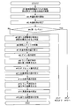
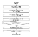
- FIG. 7 is a diagram showing an example of processing at the time of power saving mode cancellation in the multifunction peripheral according to the embodiment.
- the MFP 100 will be described as an example of the image reading apparatus.
- the multifunction peripheral 100 can print and transmit in addition to reading an original.
- the multifunction peripheral 100 is also an image forming apparatus.
- the respective elements such as the configuration and arrangement described in the description of the present embodiment do not limit the scope of the invention and are merely illustrative examples.
- FIG. 1 is a diagram illustrating an example of a multifunction peripheral 100 according to the embodiment.
- the MFP 100 includes a main control unit 1, a storage unit 2, an operation panel 3, a printing unit 4, a communication unit 5, and an image reading unit 6.
- the main control unit 1 controls the multifunction device 100.
- the main control unit 1 includes a CPU 11 and an image processing unit 12.
- the storage unit 2 includes a non-volatile storage device such as a ROM, a flash ROM, and a storage (HDD).
- the storage unit 2 also includes a volatile storage device such as a RAM.
- the main control unit 1 controls each unit using a program or data stored in the storage unit 2. In a job such as copying and transmission, the main control unit 1 controls document reading. Further, the main control unit 1 controls printing, transmission, and storage of image data.
- the image processing unit 12 performs image processing on image data.
- Operation panel 3 includes a display panel 31, a touch panel 32, and a hard key 33.
- the main control unit 1 causes the display panel 31 to display a setting screen and an operation image.
- the operation image is, for example, a button, a key, or a tab.
- the main control unit 1 Based on the output of the touch panel 32, the main control unit 1 recognizes the operated image for operation.
- the hard key 33 includes a start key and a ten key.
- the touch panel 32 and the hard key 33 receive the setting operation (operation related to the job) of the user.
- the main control unit 1 communicates with the operation panel 3.
- the main control unit 1 recognizes the setting content.
- the printing unit 4 includes a sheet feeding unit 4 a, a sheet conveyance unit 4 b, an image forming unit 4 c, and a fixing unit 4 d.
- the main control unit 1 supplies a sheet to the sheet feeding unit 4a.
- the main control unit 1 transports the sheet to the sheet transport unit 4b.
- the sheet conveyance unit 4b discharges the printed sheet to the outside of the machine.
- the main control unit 1 causes the image forming unit 4 c to form a toner image based on the image data.
- the main control unit 1 causes the image forming unit 4 c to transfer the toner image to the transport sheet.
- the main control unit 1 causes the fixing unit 4 d to fix the transferred toner image on the sheet.
- the main control unit 1 controls the operation of the printing unit 4.
- the communication unit 5 is communicably connected to the computer 200.
- the communication unit 5 and the computer 200 communicate via a network.
- the communication unit 5 includes a communication circuit and communication software.
- the communication unit 5 receives the print data transmitted from the computer 200.
- the print data includes image data and data described in a page description language.
- the main control unit 1 causes the printing unit 4 to print based on the received print data (print job).
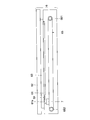
- FIGS. 2 and 3 are diagrams showing an example of the image reading unit 6 according to the embodiment.
- a document glass 61 (corresponding to a document table) is disposed on the upper right side of the image reading unit 6.
- the original glass 61 transmits light.
- the original is set on an original glass 61.
- the image reading unit 6 applies light to the document set on the document glass 61.
- the image processing unit 12 reads the lower side of the document to generate image data.
- the main control unit 1 stores the generated image data in the storage unit 2.
- a document pressing unit 62 is provided above the image reading unit 6.
- the document pressing unit 62 can be opened and closed.
- the document pressing unit 62 can be opened and closed so that the front side of the multifunction device 100 is swung up and down.
- FIG. 2 shows a state in which the document pressing unit 62 is closed.
- a document pressing plate 63 is attached to the lower surface of the document pressing unit 62.
- the document pressing plate 63 is, for example, a white plate.
- the document pressing plate 63 covers the document glass 61 from above.
- the document pressing plate 63 presses the document set on the document glass 61 from above.
- a document conveyance device may be attached instead of the document holding unit 62.
- the document transport unit also presses the document on the document glass 61.
- the document conveying device is a device for conveying a document which has been automatically set one by one.
- the image reading unit 6 is provided with a conveyance reading glass 61 a.
- the transport reading glass 61 a is provided on the left side of the original glass 61.
- the conveyed original passes over the conveyance reading glass 61a.
- the reading control unit 60 positions the reading unit 7 below the conveyance reading glass 61 a.
- the image reading unit 6 includes a reading control unit 60.
- the reading control unit 60 is a substrate that controls the operation of the image reading unit 6.
- the read control unit 60 includes a control circuit 60a, a memory 60b, and other circuits.
- the reading control unit 60 receives an instruction and a signal from the main control unit 1 and reads an original.
- the image reading unit 6 includes a reading unit 7, a white reference plate 64, a belt 65, a pulley 661, and a pulley 662.
- the reading unit 7 is a CIS scanning unit.
- the belt 65, the pulleys 661, and the pulleys 662 are mechanisms for moving the reading unit 7.
- the belt 65 is endless.
- Belt 65 is wound around each pulley.
- the belt 65 and the reading unit 7 are connected.
- a scanning motor 67 is provided in the image reading unit 6 (see FIG. 3).
- the scanning motor 67 rotates the pulley 662.
- the scanning motor 67 can rotate in forward and reverse directions.
- the reading control unit 60 rotates the scanning motor 67. Thereby, the belt 65 turns.
- the reading unit 7 moves in the horizontal direction (sub-scanning direction, right and left direction in FIG. 2).
- the reading control unit 60 moves the reading unit 7 in the sub-scanning direction.
- the white reference plate 64 is provided in the vicinity of the document glass 61 (left side in FIG. 2).
- the white reference plate 64 is provided at a position where the reading unit 7 can read.
- the reading unit 7 includes a lamp 71 and an image sensor 72.
- the reading unit 7 reads the document set on the document glass 61.
- a lamp 71 emits light to the document.
- the image sensor 72 includes a plurality of light receiving elements (pixels). The light receiving elements are arranged in the main scanning direction.
- the image sensor 72 is, for example, a line sensor.
- the light reflected by the document or document pressing plate 63 enters the light receiving element.
- Each light receiving element outputs an analog image signal according to the amount of light received (the amount of reflected light).
- the image reading unit 6 includes a data generation circuit unit 8. Based on the analog image signal output from the image sensor 72, the data generation circuit unit 8 generates image data.
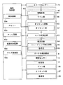
- FIG. 4 is a view showing an example of the reading control unit 60 and the data generation circuit unit 8 according to the embodiment.
- the read control unit 60 includes a plurality of devices.
- the read control unit 60 includes a control circuit 60a, a memory 60b, a PLL circuit 60c, and a start control circuit 60d.
- the data generation circuit unit 8 also includes a plurality of devices.
- the data generation circuit unit 8 includes, as devices, an amplification circuit 81, an offset circuit 82, an A / D conversion circuit 83, and a correction circuit 84.
- the control circuit 60 a is, for example, the CPU 11.
- the memory 60 b stores data for controlling the operation of the image reading unit 6 and a program.
- the control circuit 60a operates based on data and programs stored in the memory 60b.
- the PLL circuit 60c is a circuit that generates a signal of a preset frequency. For example, the PLL circuit 60c generates a clock signal for charge transfer of each light receiving element (image sensor 72). The clock signal generated by the PLL circuit 60 c is supplied to the image sensor 72. The PLL circuit 60 c may generate a clock signal for the synchronization signal of the image sensor 72. The PLL circuit 60c may generate a clock signal for operation of the control circuit 60a. The PLL circuit 60c may generate a clock signal for operating the memory 60b. The destination (device) of the signal generated by the PLL circuit 60c is predetermined.
- the start control circuit 60d controls the start of each device.
- power supply to the image reading unit 6 (reading control unit 60, data generation circuit unit 8) is started, activation of each device is started in a predetermined order.
- the order of power supply to each device is determined in advance.
- the start control circuit 60d is connected to all or part of the devices by a reset signal line.
- the start control circuit 60d releases the reset signal in a predetermined order. The device whose reset signal is released starts the boot process.
- the amplification circuit 81, the offset circuit 82, and the A / D conversion circuit 83 are parts (analog processing unit 80) that process an analog image signal of the image sensor 72.
- the analog processing unit 80 may be referred to as an AFE.
- the output of each light receiving element of the image sensor 72 is input to the amplification circuit 81.
- the amplification circuit 81 amplifies an analog image signal from each light receiving element.
- the amplifier circuit 81 stores the gain value 86.
- the amplification circuit 81 includes a memory (setting register) for storing the gain value 86.
- the read control unit 60 writes the gain value 86 into the memory.
- the reading control unit 60 sets a gain value 86 (details will be described later).
- the amplification circuit 81 amplifies the analog image signal with the set gain (amplification factor).
- the amplified analog image signal is input to the offset circuit 82.
- the offset circuit 82 adjusts the analog image signal by the output of each light receiving element of the image sensor 72 when the lamp 71 is turned off.
- the offset circuit 82 stores an offset value 87.
- the offset circuit 82 includes a memory (setting register) for storing the offset value 87.
- the reading control unit 60 sets an offset value 87 (details will be described later).
- the offset circuit 82 changes the analog image signal by the set offset value 87.
- the analog image signal adjusted by the offset circuit 82 is input to the A / D conversion circuit 83.
- the A / D conversion circuit 83 converts the input analog signal into a digital signal.
- the A / D conversion circuit 83 generates image data.
- the generated image data is input to the correction circuit 84. Due to the characteristics of the lamp 71, the image sensor 72, and the data generation circuit unit 8, distortion may occur in the image data.
- the correction circuit 84 is a circuit that corrects distortion of image data.
- the correction circuit 84 includes a shading correction circuit 85.
- the correction circuit 84 may include other types of correction circuits.
- the shading correction circuit 85 performs shading correction based on the reference value 88 determined for each light receiving element.
- the shading correction circuit 85 stores the reference value 88.
- the reference values 88 include white reference values and black reference values.
- the reading control unit 60 sets a reference value 88 (details will be described later).
- the shading correction circuit 85 includes a memory (register) for storing the reference value 88.
- the shading correction circuit 85 performs a shading correction operation based on the black reference value and the white reference value.
- the shading correction circuit 85 may perform shading correction using another arithmetic expression.
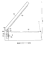
- FIG. 5 is a view showing an example of open / close detection of the document pressing unit 62 according to the embodiment.
- a support member 68 is provided on the back of the image reading unit 6.
- the document pressing unit 62 is attached to the support member 68.
- a rotating shaft 69 is provided at the upper end of the support member 68.
- the rotating shaft 69 is inserted at the end on the back side of the document pressing portion 62.
- the document pressing portion 62 can be rotated by swinging the front side up and down by the rotating shaft 69.
- the end on the front side of the multifunction device 100 of the document pressing unit 62 is a free end.
- the document pressing portion 62 can be open or closed with respect to the upper surface of the document glass 61.
- a document pressing plate 63 is provided as a part of the document pressing unit 62.
- the document pressing plate 63 covers the document glass 61.
- the document pressing plate 63 and the document glass 61 are in contact with each other.
- the document pressing plate 63 holds the document so as not to move.
- the open / close sensor 9 includes an abutment member 91, a transmission type light sensor 92, and a biasing member 93.
- the biasing member 93 biases the contact member 91 upward.
- the contact member 91 has the vertical direction as the longitudinal direction.
- the contact member 91 is a rod-like member. The position of the contact member 91 changes in the vertical direction according to the opening and closing of the document pressing unit 62. Due to the biasing of the biasing member 93, the contact member 91 is moved upward as the document pressing portion 62 is opened. Then, it protrudes from the upper surface of the image reading unit 6.
- the upper end portion 94 of the contact member 91 contacts the lower surface 2 e of the document pressing portion 62. Then, the contact member 91 is pushed downward as the document pressing portion 62 is closed (as it is turned over).
- a sensor interference unit 95 is provided below the contact member 91.
- the transmissive light sensor 92 detects that the contact member 91 (the sensor interference unit 95) has reached a predetermined position or less. In other words, the transmissive light sensor 92 detects that the document pressing unit 62 is closed more than a predetermined angle.
- the transmissive light sensor 92 includes a light emitting unit and a light receiving unit (not shown). The sensor interference unit 95 moves up and down between the light emitting unit and the light receiving unit. When the angle of the document pressing unit 62 becomes a predetermined angle, the output level of the light receiving unit changes.
- the predetermined angle is appropriately determined.
- the state in which the document pressing unit 62 is completely closed is assumed to be 0 degrees.
- the predetermined angle is, for example, any angle within the range of 15 degrees to 60 degrees.
- the position of the contact member 91 is set such that the output levels (High and Low) of the transmission type light sensor 92 change at a predetermined angle.
- the biasing member 93 biases the contact member 91 so that the output of the transmission type light sensor 92 changes at a predetermined angle.
- the open / close sensor 9 (transmission type light sensor 92) outputs the first level when the document pressing unit 62 is opened by a predetermined angle or more. When it is not opened more than the predetermined angle, the open / close sensor 9 outputs the second level. When the first level is high level, the second level is low level. When the first level is low level, the second level is high level.
- the output of the open / close sensor 9 is input to the reading control unit 60. Based on the output level of the open / close sensor 9, the reading control unit 60 recognizes whether the document pressing unit 62 is opened at a predetermined angle or more. In addition, when changing from the second level to the first level, the reading control unit 60 recognizes that the document pressing unit 62 has been opened by a predetermined angle or more. When the level changes from the first level to the second level, the reading control unit 60 recognizes that the document pressing unit 62 is closed below a predetermined angle.
- the reading control unit 60 instructs the reading unit 7 to read the document size detection. Let it go.
- the reading control unit 60 uses a change in the output level of the open / close sensor 9 as a trigger. In other words, when changing from the first level to the second level, the reading control unit 60 causes the reading unit 7 to read the document glass 61 before the document pressing unit 62 is completely closed.
- the reading control unit 60 moves the reading unit 7 from the home position to the document size detection position.
- the document size detection position is below the document glass 61.
- the document size detection position of the reading unit 7 is a position for reading a line separated by a predetermined distance from the left edge of the document glass 61 as viewed from above.
- the predetermined distance can be, for example, any value within the range of several millimeters to several centimeters.
- the home position of the reading unit 7 is predetermined.
- the home position may be below the white reference plate 64.
- a home position sensor is provided to detect that the reading unit 7 is at the home position.
- the reading control unit 60 After completion of reading, the reading control unit 60 returns the reading unit 7 to the home position.
- the reading control unit 60 stops the scanning motor 67.
- the reading control unit 60 includes a size detection unit 60e.
- the size detection unit 60e detects the size of the document in the main scanning direction.
- the size detection unit 60e may be provided as hardware (circuit). Further, the size detection unit 60e may be realized as software by the control circuit 60a or a program.
- the size detection unit 60e detects the size based on image data (hereinafter, referred to as “detection image data”) obtained by reading the left end portion of the document glass 61. In the reading before the document pressing unit 62 is completely closed, the light of the portion where the document does not exist is not reflected but leaks to the outside.
- the pixel value of the pixel in the portion where the document does not exist is darker than the pixel value of the pixel in the portion where the document exists.
- the size detection unit 60e compares the pixel value of each pixel in the detection image data with a predetermined threshold value. Based on the comparison, the size detection unit 60e determines the position of the boundary between the pixel range in which the document is read and the pixel range in which the portion without the document is read.
- the threshold is stored in a non-volatile manner in a storage device such as the memory 60 b.
- the size determination unit obtains the size (width) in the main scanning direction of the document. For example, the reading control unit 60 counts the number of pixels from the pixel corresponding to the position of the reference point to the boundary position. The pitch of one pixel is fixed in view of the reading resolution (if the resolution is 600 dpi, 25.4 [mm] ⁇ 600 ⁇ 42.3 [ ⁇ m] per pixel). Therefore, the reading control unit 60 multiplies the number of pixels from the pixel corresponding to the position of the reference point to the boundary position (the number of pixels in the main scanning direction) by the pitch of one pixel. Thus, the reading control unit 60 obtains the size of the document in the main scanning direction.
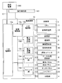
- FIG. 6 is a diagram illustrating an example of power supply in the multifunction peripheral 100 according to the embodiment.
- the multifunction peripheral 100 includes a power supply device 10.
- the power supply device 10 includes a primary power supply unit 10a, a secondary power supply unit 10b, and a power control unit 10c.
- the power supply cord C1 connects the commercial power supply 300 and the primary power supply unit 10a.
- the primary power supply unit 10a generates a DC voltage from the commercial power supply 300 (AC voltage).
- the primary power supply unit 10a generates a preset voltage. For example, the primary power supply unit 10 a generates DC 24 V for driving a motor.
- the multifunction peripheral 100 includes various circuits and elements.
- the types of voltage required for the operation of each circuit and each element also extend to a plurality of types.
- a plurality of types of voltages are required for operations of the main control unit 1, the storage unit 2, the operation panel 3, the printing unit 4, the communication unit 5, and the image reading unit 6. Therefore, the secondary power supply unit 10b generates a plurality of types of direct current voltages based on the generated voltage of the primary power supply unit 10a.
- the secondary power supply unit 10 b includes a plurality of power conversion circuits 10 d.
- the power conversion circuit 10d is a DC converter or a regulator.
- the magnitude of the output voltage of each power conversion circuit 10d is preset.
- the power supply control unit 10 c controls ON / OFF of each power conversion circuit 10 d.
- the secondary power supply unit 10 b generates and supplies a voltage having a magnitude necessary for operation.
- the secondary power supply unit 10b includes the main control unit 1 (CPU 11, image processing unit 12), storage unit 2, operation panel 3, printing unit 4, communication unit 5, image reading unit 6 (reading control unit 60, reading unit 7. Generate and supply a voltage of a magnitude necessary for the operation of the data generation circuit unit 8).
- the switch unit 10 e is provided so that the power supply can be stopped only at the portion where the supply is not performed.
- the switch unit 10 e is a switching element such as a transistor.
- a plurality of switch parts 10e are provided.
- the switch unit 10e is provided between the supply destination and the power conversion circuit 10d.
- the power control unit 10 c controls ON / OFF of each switch unit 10 e.
- the multifunction peripheral 100 has an active mode (normal mode) and a power saving mode.
- the power saving mode is a mode which reduces power consumption more than the active mode.
- the power saving mode may be referred to as a power saving mode, a power saving mode, or a sleep mode.
- the power supply device 10 stops the power supply to the predetermined supply stop portion.
- the supply stop part is decided suitably.
- the supply stop portion is the main control unit 1, the storage unit 2, a part of the operation panel 3, the printing unit 4, and a part of the image reading unit 6.
- the reading control unit 60, the reading unit 7, and the data generation circuit unit 8 are used as the supply stop portion.
- the main control unit 1 shifts the power supply device 10 to the power saving mode.
- Transition conditions are determined as appropriate.
- the operation to a specific hard key 33 (power saving key) provided on the operation panel 34 is a transition condition.
- the transition condition is that the time during which the operation panel 3 is not operated exceeds the predetermined transition time.
- the main control unit 1 gives the power supply device 10 a transition instruction.
- the power supply device 10 stops the power supply to the supply stop part.
- the main control unit 1 restores the power supply device 10 to the active mode.
- the release condition is determined as appropriate.
- the power supply device 10 resumes the power supply to the supply stop part.
- the power control unit 10 c supplies power to all parts of the multifunction peripheral 100.
- the power control unit 10 c is connected to the operation detection unit 101 via an interrupt signal line.
- the interrupt signal is input to the power control unit 10c.
- the power supply control unit 10c determines that the release condition is satisfied.
- the operation detection unit 101 is a unit that detects an operation or an input to the multifunction peripheral 100.
- the operation detection unit 101 is the communication unit 5.
- the communication unit 5 changes the level of the interrupt signal.
- the operation detection unit 101 may be the open / close sensor 9.
- the output of the open / close sensor 9 is input to the power control unit 10c.
- the power control unit 10c may determine that the release condition is satisfied.
- the operation detection unit 101 may be the operation panel 3.
- the operation panel 3 changes the level of the interrupt signal.
- the operation detection unit 101 is not limited to the above example. Other sensors or circuits may be used as the operation detection unit 101.
- the power supply device 10 supplies power to the operation detection unit 101 even in the power saving mode in order to determine the release condition.
- the operation detection unit 101 is excluded from the supply stop part.
- the open / close sensor 9 is excluded from the supply stop portion.
- FIG. 7 and FIG. 8 are diagrams showing an example of processing at the time of canceling the power saving mode in the MFP 100 according to the embodiment.
- the read control unit 60 determines a new adjustment value as one of the start processing. Then, the read control unit 60 sets the operation of the data generation circuit unit 8 with the determined adjustment value.
- the adjustment value includes a gain value 86, an offset value 87, and a reference value 88. It may take several seconds to set a new adjustment value and set the operation.
- the reading unit 7 performs reading a plurality of times (details will be described later). Therefore, while setting a new adjustment value and setting an operation, document size detection can not be performed.
- document size detection may need to be prioritized over acquisition of a new adjustment value.
- the user may operate the operation panel 3 to cancel the power saving mode. After operating the operation panel 3, the user may immediately set the document on the document glass 61 and close (downward) the document pressing unit 62. At this time, when the reading unit 7 is used for obtaining a new adjustment value when the document pressing unit 62 is closed below a predetermined angle, the document size can not be detected. Therefore, at the time of releasing the power saving mode, the reading control unit 60 appropriately determines whether or not the document size detection should be prioritized regardless of the reason (factor) for releasing the power saving mode.
- FIG. 7 is when the power saving mode is released.
- the common process is a predetermined process.
- the common process includes a process for stabilizing the read control unit 60, the data generation circuit unit 8, and the read unit 7 to enable operation.
- the common process can be said to be a preparation process for using the reading unit 7.
- the start control circuit 60d waits for a predetermined waiting time after resuming power supply to the image reading unit 6 (reading control unit 60, data generation circuit unit 8). This is to wait for stabilization of the power conversion circuit 10 d that supplies power to the image reading unit 6.
- the activation control circuit 60d performs, as a common process, a process of starting activation of devices in order.
- the start control circuit 60d releases the reset in a predetermined order. When the reset is released, the control circuit 60a, the memory 60b, the PLL circuit 60c, the circuit included in the data generation circuit unit 8, and the circuit included in the reading unit 7 start up.
- control circuit 60a communicates with the memory 60b, the PLL circuit 60c, the start control circuit 60d, the amplification circuit 81, the offset circuit 82, the A / D conversion circuit 83, and the correction circuit 84 (shading correction circuit 85). Establish. Further, as a common process, the control circuit 60a may confirm the presence or absence of an abnormality in the image sensor 72 and the lamp 71.
- the PLL circuit 60c performs processing of increasing the frequency of the clock signal to the set frequency (waiting for lock).
- the control circuit 60a performs a process of checking whether or not the phase lock in the PLL circuit 60c is completed.
- the predetermined common processing is eventually completed (step # 3). Then, the read control unit 60 checks whether the output level of the open / close sensor 9 is the first level (step # 4). In other words, the reading control unit 60 checks whether the document pressing unit 62 is opened by a predetermined angle or more.
- the reading control unit 60 determines to give priority to acquisition and setting of a new adjustment value (step # 5).
- the reading control unit 60 gives priority to obtaining a new adjustment value.
- the reading control unit 60 obtains a gain value 86, an offset value 87, a white reference value, and a black reference value as adjustment values.
- the reading control unit 60 may obtain values other than these as adjustment values.
- the reading control unit 60 moves the reading unit 7 below the white reference plate 64 (step # 6). Then, the reading control unit 60 turns on the lamp 71. The reading control unit 60 causes the reading unit 7 to read the white reference plate 64 (step # 7). Based on the reading result of the white reference board 64, the reading control unit 60 determines and sets the gain value 86 (step # 8). For example, the reading control unit 60 causes the maximum value of the analog image signal of each pixel obtained by reading the white reference plate 64 to coincide with the upper limit value of the conversion range (voltage range) of the A / D conversion circuit 83. Alternatively, the gain value 86 is set so as to be a value slightly smaller than the upper limit value. Then, the read control unit 60 writes the determined gain value 86 in the memory (register) of the amplification circuit 81. Thus, acquisition and setting of a new gain value 86 are completed.
- the reading control unit 60 turns off the lamp 71 and causes the reading unit 7 to output the reading result when the lamp 71 is turned off. (Step # 9). Based on the reading result when the lamp 71 is turned off, the reading control unit 60 obtains and sets the offset value 87 (step # 10). For example, the reading control unit 60 determines the offset value 87 such that the minimum value of the analog image signal of each pixel when the lamp 71 is turned off matches the lower limit value of the conversion range (voltage range) of the A / D conversion circuit 83. Then, the read control unit 60 writes the determined offset value 87 in the memory (register) of the offset circuit 82. Acquisition and setting of a new offset value 87 are completed.
- the reading control unit 60 lights the lamp 71, and the reading control unit 60 causes the reading unit 7 to read the white reference plate 64 (step # 11). Based on the reading result of the white reference plate 64, the reading control unit 60 acquires and sets the white reference value (step # 12). For example, the reading control unit 60 sets the digital value of the analog image signal of each pixel obtained by the reading of the white reference plate 64 as the white reference value. Then, the reading control unit 60 writes the determined white reference value in the memory (register) of the shading correction circuit 85. This completes the acquisition and setting of a new white reference value.
- the reading control unit 60 turns off the lamp 71 and causes the reading unit 7 to output the reading result when the lamp 71 is turned off. (Step # 13). Based on the reading result when the lamp 71 is turned off, the reading control unit 60 acquires and sets the black reference value (step # 14). For example, the reading control unit 60 sets the digital value of the analog image signal of each pixel when the lamp 71 is turned off as the black reference value. Then, the reading control unit 60 writes the determined black reference value in the memory (register) of the shading correction circuit 85. Acquisition and setting of new black reference values are complete.
- the read control unit 60 stores the newly determined adjustment value in the storage unit 2 (which may be the memory 60b) in a non-volatile manner (step # 15).
- the read control unit 60 causes the storage unit 2 to update each adjustment value.
- the reading control unit 60 rewrites the adjustment value of the storage unit 2. Then, the flow ends (end).
- step # 16 the reading control unit 60 determines to give priority to document size detection (step # 16).
- the reading control unit 60 gives priority to document size detection over acquisition of a new adjustment value.
- the read control unit 60 sets the gain value 86 stored in the storage unit 2 (step # 17). As described above, each time the gain value 86 is newly determined, the reading control unit 60 causes the storage unit 2 to update the gain value 86. When priority is given to document size detection, the gain value 86 stored in the storage unit 2 is the gain value 86 determined before the transition to the power saving mode.
- the read control unit 60 writes the previous gain value 86 into the memory of the amplifier circuit 81.
- the read control unit 60 sets the operation of the amplification circuit 81 using the previous gain value 86.
- the read control unit 60 sets the offset value 87 stored in the storage unit 2 (step # 18). As described above, each time the gain value 86 is newly determined, the reading control unit 60 causes the storage unit 2 to update the offset value 87. Therefore, when priority is given to document size detection, the offset value 87 stored in the storage unit 2 is the offset value 87 determined before the transition to the power saving mode.
- the read control unit 60 writes the previous offset value 87 into the memory of the offset circuit 82.
- the read control unit 60 sets the operation of the offset circuit 82 using the previous offset value 87.
- the reading control unit 60 sets the reference values 88 (white reference value, black reference value) stored in the storage unit 2 (step # 19). As described above, each time the reference value 88 is newly determined, the reading control unit 60 causes the storage unit 2 to update the reference value 88. Therefore, when priority is given to document size detection, the reference value 88 stored in the storage unit 2 is the reference value 88 determined before the transition to the power saving mode.
- the read control unit 60 writes the previous reference value 88 in the memory of the shading correction circuit 85.
- the reading control unit 60 sets the operation of the shading correction circuit 85 using the previous reference value 88.
- Each adjustment value may change before and after the transition to the power saving mode. However, since there is little dramatic change, it is possible to accurately detect the document size even using the previous adjustment value. Then, the read control unit 60 continues to check whether the output of the open / close sensor 9 has changed from the first level to the second level (step # 20, No in step # 20 ⁇ step # 20). As long as the document pressing unit 62 is open, the document pressing unit 62 is eventually closed. The reading control unit 60 waits for the document pressing unit 62 to close.
- the reading control unit 60 causes the reading unit 7 to read the document glass 61 (step # 21). . At this time, the reading control unit 60 operates the scanning motor 67. Then, the reading control unit 60 moves the reading unit 7 below the document glass 61.
- the reading control unit 60 detects the size of the document in the main scanning direction based on the image data obtained by reading (step # 22). Then, the flow moves to step # 5.
- the reading control unit 60 determines each adjustment value. Further, the reading control unit 60 sets each adjustment value.
- the image reading apparatus includes the document table (document glass 61), the reading control unit 60, the reading unit 7, the data generation circuit unit 8, the document pressing unit 62, the open / close sensor 9, the power supply device 10, A storage unit 2 is included.
- the reading unit 7 includes an image sensor 72 and reads an original set on an original table.
- the data generation circuit unit 8 generates image data based on the output of the image sensor 72.
- the document pressing unit 62 can be opened and closed, and presses the document table.
- the open / close sensor 9 outputs the first level when the document pressing unit 62 is opened by a predetermined angle or more.
- the open / close sensor 9 outputs the second level when it is not opened more than a predetermined angle.
- the power supply device 10 stops the power supply to the reading control unit 60 and the data generation circuit unit 8 in the power saving mode.
- the power supply device 10 supplies power to the reading control unit 60 and the data generation circuit unit 8 in the active mode.
- the storage unit 2 stores adjustment values for setting the operation of the data generation circuit unit 8.
- the reading control unit 60 performs a predetermined common process.
- the reading control unit 60 confirms the output of the open / close sensor 9 when the common processing is completed.
- the reading control unit 60 sets the operation of the data generation circuit unit 8 based on the adjustment value of the storage unit 2.
- the reading control unit 60 causes the reading unit 7 to perform reading for document size detection.
- the reading control unit 60 detects the size of the document based on the reading result.
- the common processing includes processing for stabilizing the devices included in the read control unit 60 and the data generation circuit unit 8 and enabling the devices.
- the reading control unit 60 instructs the reading unit 7 to newly set the adjustment value without detecting the size of the document.
- the operation of the data generation circuit unit 8 is set based on the newly determined adjustment value. If the document pressing unit 62 is closed at the completion of the common processing, there is a high possibility that the user does not set the document. When it is not necessary to give priority to document size detection, it is possible to give priority to acquisition of new adjustment values and setting of the data generation circuit unit 8.
- the reading control unit 60 detects the size of the document and then causes the reading unit 7 to perform reading for newly setting adjustment values.
- the operation of the data generation circuit unit 8 is set based on the newly determined adjustment value.
- the reading control unit 60 causes the reading unit 7 to read the document table, and the document is read based on the image data obtained by the reading. Detect the size in the main scanning direction. As a result, when the document pressing unit 62 is closed to a certain extent, reading for document size detection can be performed. This makes it easy to understand the boundary between the portion where the document is present and the portion where the document is not present. The size of the document can be detected accurately.
- the data generation circuit unit 8 includes an amplification circuit 81, an offset circuit 82, and a shading correction circuit 85.
- the read control unit 60 defines, as adjustment values, a gain value 86 used to set the amplification circuit 81, an offset value 87 used to set the offset circuit 82, and a reference value 88 used to set the shading correction circuit 85.
- the read control unit 60 stores the newly determined gain value 86, offset value 87, and reference value 88 in the storage unit 2 in a non-volatile manner.
- the amplifier circuit 81, the offset circuit 82, and the shading correction circuit 85 become available, it can be determined whether or not the first process is to be performed. Further, when priority is given to document size detection, document size detection can be performed without setting new gain values 86, offset values 87, and reference values 88. Further, the latest adjustment value can be stored in the storage unit 2.
- the read control unit 60 includes a control circuit 60a, a memory 60b, a PLL circuit 60c, and a start control circuit 60d.
- the start control circuit 60d sequentially performs reset cancellation as a common process, thereby controlling the control circuit 60a, the memory 60b, and the PLL circuit 60c, The start of the circuit included in the data generation circuit unit 8 is started.
- the control circuit 60a performs communication establishment with the memory 60b, the PLL circuit 60c, the start control circuit 60d, the amplification circuit 81, the offset circuit 82, the A / D conversion circuit 83, and the shading correction circuit 85 as common processing.
- the PLL circuit 60c performs processing to raise the frequency of the clock signal up to the set frequency as common processing. As described above, processing required for document size detection and setting of adjustment values can be common processing.
- the present invention is applicable to an image reading apparatus (image forming apparatus).
Landscapes
- Engineering & Computer Science (AREA)
- Multimedia (AREA)
- Signal Processing (AREA)
- Facsimile Scanning Arrangements (AREA)
- Facsimiles In General (AREA)
- Holders For Sensitive Materials And Originals (AREA)
Abstract
画像読取装置(100)は、原稿台(61)、読取制御部(60)、データ生成回路部(8)、原稿押さえ部(62)、原稿押さえ部が所定角度以上開いているとき第1レベルを出力し、所定角度未満のとき第2レベルを出力する開閉センサー(9)、電源装置(10)、調整値を記憶する記憶部(2)と、を備える。省電力モードからアクティブモードに復帰したとき、読取制御部(60)は、共通処理完了時の開閉センサー(9)の出力が第1レベルのとき、読取制御部(60)は、記憶部(2)の調整値に基づきデータ生成回路部(8)の動作を設定してから、原稿サイズ検知のための読み取りを読取ユニット(7)に行わせる。
Description
本発明は、原稿を読みとって画像データを生成する画像読取装置に関する。
画像読取装置は、原稿をイメージセンサーで読み取り、画像データを生成する。複合機や複写機は、画像読取装置の一種である。そして、画像読取装置には、読み取りで得られた画像データに基づき、セット原稿のサイズを検知するものがある。このようなサイズ検知を行う画像読取装置の一例が特許文献1に記載されている。
具体的に、特許文献1には、原稿からの光情報を受けて電気信号に変換するラインセンサーと、ラインセンサーの出力をディジタルデータに変換するA/D変換器と、画像読み取り処理の制御動作を行う制御部を備え、プラテンカバーを閉じていない状態で原稿の主走査方向の第1の走査を行ない、次に、プラテンカバーを閉じた状態で原稿の主走査方向の第2の走査を行ない、これら2回の走査で得られたラインセンサー出力を基に原稿サイズを判定する画像読取装置が記載されている(特許文献1:請求項1参照)。
省電力モードが画像読取装置に搭載されることがある。省電力モードは、消費電力を減らすモードである。省電力モードでは、予め定められた部分(供給停止部分)への電力供給が停止される。省電力モードでは、例えば、制御回路、イメージセンサー、イメージセンサーの出力に基づき画像データを生成する回路(画像処理回路)への電力供給が停止される。
省電力モードが解除されたとき、供給停止部分への電力供給が再開される。電力供給が再開されたそれぞれ部分で、起動が開始される。省電力モードが解除されたとき、原稿を読み取り、画像データを生成できる状態に戻すための復帰処理が行われる。復帰処理の過程で、読み取りを行い、読み取り結果に基づき、画像処理回路の動作(設定値)を設定することがある。例えば、画像読取装置内の白基準板の読み取りが行われる。
一方、画像読取装置では、イメージセンサーで原稿ガラスを読み取り、原稿サイズを検知することがある。つまり、原稿ガラス上の原稿が読み取られ、その結果に基づき、原稿のサイズが検知される。ここで、画像処理回路の動作を設定するとき、読み取りが行われる。また、原稿サイズを検知するときも読み取りが行われる。そのため、省電力モード解除に応じて画像処理回路の動作を設定している間、原稿サイズを検知することができない。原稿サイズの自動検知を希望する使用者は、画像処理回路の動作設定が完了するまで、待たなくてはならないという問題がある。
使用者が待たないように、画像処理回路の動作設定よりも、原稿サイズの検知を常に優先させることが考えられる。しかし、原稿サイズの検知の必要が無い場合も、画像処理回路の動作設定があとまわしとなる。通常、使用者が装置に所定の操作したとき、省電力モードが解除される。例えば、原稿を押さえる原稿押さえの開閉を省電力モードの解除トリガーとすることがある。原稿をセットする場合、原稿押さえが開閉される。そこで、原稿押さえの開閉が行われたときのみ、画像処理回路の動作の設定よりも、原稿サイズの検知を優先させることが考えられる。
しかし、言い換えれば、原稿押さえの開閉以外の復帰では、画像処理回路の動作の設定が優先されることになる。このような単純な制御では、原稿サイズ検知を優先すべきときに、原稿サイズ検知が優先されないことがある。
特許文献1に記載の技術によれば、原稿のサイズを検知することができる。しかし、省電力モード解除時の処理については、記載がない。従って、上記の問題を解決することはできない。
本発明は上記従来技術の問題点に鑑み、省電力モードの復帰要因を問わず、原稿サイズ検知を優先すべきか否かを適切に判定する。
上記目的を達成するため、請求項1に係る画像読取装置は、原稿台、読取制御部、読取ユニット、データ生成回路部、原稿押さえ部、開閉センサー、電源装置、記憶部を含む。前記読取ユニットは、イメージセンサーを含み前記原稿台にセットされた原稿を読み取る。前記データ生成回路部は、前記イメージセンサーの出力に基づき画像データを生成する。前記原稿押さえ部は、開閉可能であり、前記原稿台を押さえる。前記開閉センサーは、前記原稿押さえ部が所定角度以上開いているとき第1レベルを出力する。前記開閉センサーは、前記所定角度以上開いていないとき第2レベルを出力する。前記電源装置は、省電力モードでは前記読取制御部と前記データ生成回路部への電力供給を停止する。前記電源装置は、アクティブモードでは前記読取制御部と前記データ生成回路部に電力を供給する。前記記憶部は、前記データ生成回路部の動作を設定するための調整値を記憶する。前記省電力モードから前記アクティブモードに復帰した場合、前記読取制御部は予め定められた共通処理を行う。前記読取制御部は、前記共通処理の完了時に前記開閉センサーの出力を確認する。前記開閉センサーの出力が前記第1レベルのとき、前記読取制御部は、前記記憶部の前記調整値に基づき前記データ生成回路部の動作を設定する。前記読取制御部は、設定後、原稿サイズ検知のための読み取りを前記読取ユニットに行わせる。前記読取制御部は、読み取り結果に基づき、原稿のサイズを検知する。前記共通処理は、前記読取制御部と前記データ生成回路部に含まれるデバイスを安定させ、前記デバイスを動作可能とするための処理を含む。
本発明によれば、省電力モードの復帰要因を問わず、原稿サイズ検知を優先すべきか否かを適切に判定することができる。
以下、図1~図8を用い、実施形態に係る画像読取装置を説明する。画像読取装置として複合機100を例に挙げて説明する。複合機100は、原稿読み取りの他、印刷、送信が可能である。複合機100は画像形成装置でもある。本実施形態の説明に記載されている構成、配置等の各要素は発明の範囲を限定せず単なる説明例にすぎない。
(複合機100)
図1を用いて、実施形態に係る複合機100の一例を説明する。図1は、実施形態に係る複合機100の一例を示す図である。
図1を用いて、実施形態に係る複合機100の一例を説明する。図1は、実施形態に係る複合機100の一例を示す図である。
図1に示すように、複合機100は、主制御部1、記憶部2、操作パネル3、印刷部4、通信部5、画像読取部6を含む。
主制御部1は、複合機100を制御する。主制御部1は、CPU11と画像処理部12を含む。記憶部2は、ROM、フラッシュROM、ストレージ(HDD)のような不揮発性の記憶装置を含む。記憶部2はRAMのような揮発性の記憶装置も含む。主制御部1は、記憶部2に記憶されたプログラムやデータを利用して各部を制御する。コピーや送信のようなジョブにおいて、主制御部1は原稿読取を制御する。また、主制御部1は印刷、送信、画像データの記憶を制御する。画像処理部12は画像データに画像処理を行う。
操作パネル3は、表示パネル31、タッチパネル32、ハードキー33を含む。主制御部1は、設定用画面や操作用画像を表示パネル31に表示させる。操作用画像は、例えば、ボタン、キー、タブである。タッチパネル32の出力に基づき、主制御部1は、操作された操作用画像を認識する。ハードキー33はスタートキーやテンキーを含む。タッチパネル32、ハードキー33は使用者の設定操作(ジョブに関する操作)を受け付ける。主制御部1は操作パネル3と通信する。主制御部1は設定内容を認識する。
印刷部4は、給紙部4a、用紙搬送部4b、画像形成部4c、定着部4dを含む。印刷ジョブのとき、主制御部1は用紙を給紙部4aに供給させる。主制御部1は用紙を用紙搬送部4bに搬送させる。用紙搬送部4bは印刷済み用紙を機外に排出する。主制御部1は画像データに基づくトナー像を画像形成部4cに形成させる。主制御部1は搬送用紙へのトナー像の転写を画像形成部4cに行わせる。主制御部1は転写されたトナー像の用紙への定着を定着部4dに行わせる。主制御部1は印刷部4の動作を制御する。
通信部5は、コンピューター200と通信可能に接続される。通信部5とコンピューター200は、ネットワークを介して通信する。通信部5は、通信用回路、通信用ソフトウェアを含む。通信部5はコンピューター200から送信された印刷用データを受信する。印刷用データは画像データやページ記述言語で記述されたデータを含む。主制御部1は受信した印刷用データに基づき、印刷部4に印刷させる(プリントジョブ)。
(画像読取部6)
次に、図2、3を用いて、実施形態に係る画像読取部6を説明する。図2、図3は、実施形態に係る画像読取部6の一例を示す図である。
次に、図2、3を用いて、実施形態に係る画像読取部6を説明する。図2、図3は、実施形態に係る画像読取部6の一例を示す図である。
画像読取部6の上面右側に、原稿ガラス61(原稿台に相当)が配される。原稿ガラス61は光を透過する。原稿は原稿ガラス61にセットされる。画像読取部6は、原稿ガラス61にセットされた原稿に光を照射する。画像処理部12は原稿の下側の面を読み取って画像データを生成する。主制御部1は生成された画像データを記憶部2に記憶させる。
図2に示すように、原稿押さえ部62が画像読取部6の上方に設けられる。原稿押さえ部62は開閉できる。複合機100の手前側を上下に振るように、原稿押さえ部62を開閉することができる。図2は、原稿押さえ部62が閉じられた状態を示す。原稿押さえ部62の下面には、原稿押さえ板63が取り付けられる。原稿押さえ板63は、例えば、白色の板である。原稿押さえ部62を閉じたとき、原稿押さえ板63は原稿ガラス61を上から覆う。原稿押さえ板63は、原稿ガラス61にセットされた原稿を上から押さえる。
なお、原稿押さえ部62の代わりに、原稿搬送装置が取り付けられてもよい。原稿搬送部も原稿を原稿ガラス61上の原稿を押さえる。原稿搬送装置は、自動的に1枚ずつセットされた原稿を搬送する装置である。搬送原稿の読み取りのため、画像読取部6には搬送読取用ガラス61aが設けられる。図2において、搬送読取用ガラス61aは、原稿ガラス61の左側に設けられる。搬送原稿は搬送読取用ガラス61a上を通過する。この場合、読取制御部60は、搬送読取用ガラス61aの下方に読取ユニット7を位置させる。
図3に示すように、画像読取部6は読取制御部60を含む。読取制御部60は画像読取部6の動作を制御する基板である。読取制御部60は、制御回路60a、メモリー60b、その他の回路を含む。読取制御部60は主制御部1からの指示、信号を受け、原稿の読み取りを行う。
図2に示すように、画像読取部6は、読取ユニット7、白基準板64、ベルト65、プーリー661、プーリー662を含む。読取ユニット7はCIS方式のスキャンユニットである。ベルト65、プーリー661、プーリー662は、読取ユニット7を移動させるための機構である。ベルト65は無端状である。ベルト65は各プーリーにかけ回される。ベルト65と読取ユニット7は接続される。走査用モーター67が画像読取部6に設けられる(図3参照)。走査用モーター67はプーリー662を回転させる。走査用モーター67は正逆回転可能である。読取ユニット7を移動させるとき、読取制御部60は走査用モーター67を回転させる。これにより、ベルト65が周回する。ベルト65の周回にあわせ、読取ユニット7は水平方向(副走査方向、図2の左右方向)で移動する。原稿を読み取るとき、読取制御部60は、読取ユニット7を副走査方向に移動させる。また、白基準板64は原稿ガラス61の近傍(図2の左側)に設けられる。白基準板64は読取ユニット7が読み取り可能な位置に設けられる。
図3に示すように、読取ユニット7はランプ71とイメージセンサー72を含む。読取ユニット7は原稿ガラス61にセットされた原稿を読み取る。ランプ71は原稿に光を照射する。イメージセンサー72は複数の受光素子(画素)を含む。受光素子は主走査方向に並べられる。イメージセンサー72は、例えば、ラインセンサーである。原稿又は原稿押さえ板63で反射された光は、受光素子に入射する。各受光素子は、受光量(反射光量)に応じたアナログ画像信号を出力する。また、画像読取部6はデータ生成回路部8を含む。イメージセンサー72から出力されたアナログ画像信号に基づき、データ生成回路部8は画像データを生成する。
(読取制御部60とデータ生成回路部8)
次に、図4を用いて、実施形態に係る読取制御部60とデータ生成回路部8の一例を説明する。図4は、実施形態に係る読取制御部60とデータ生成回路部8の一例を示す図である。
次に、図4を用いて、実施形態に係る読取制御部60とデータ生成回路部8の一例を説明する。図4は、実施形態に係る読取制御部60とデータ生成回路部8の一例を示す図である。
読取制御部60は複数のデバイスを含む。例えば、デバイスとして、読取制御部60は、制御回路60a、メモリー60b、PLL回路60c、起動制御回路60dを含む。また、データ生成回路部8も複数のデバイスを含む。データ生成回路部8は、デバイスとして、増幅回路81、オフセット回路82、A/D変換回路83、補正回路84を含む。
制御回路60aは、例えば、CPU11である。メモリー60bは、画像読取部6の動作を制御するためのデータ、プログラムを記憶する。制御回路60aは、メモリー60bが記憶するデータ、プログラムに基づき動作する。
PLL回路60cは、予め設定された周波数の信号を生成する回路である。例えば、PLL回路60cは、各受光素子(イメージセンサー72)の電荷転送用クロック信号を生成する。PLL回路60cが生成したクロック信号は、イメージセンサー72に供給される。なお、PLL回路60cは、イメージセンサー72の同期信号用のクロック信号を生成してもよい。また、PLL回路60cは、制御回路60aの動作用クロック信号を生成してもよい。PLL回路60cはメモリー60bの動作用クロック信号を生成してもよい。PLL回路60cが生成する信号の供給先(デバイス)は予め定められる。
起動制御回路60dは各デバイスの起動を制御する。画像読取部6(読取制御部60、データ生成回路部8)への電力供給が開始されたとき、予め定められた順番で各デバイスの起動を開始させる。読取制御部60やデータ生成回路部8を正常に起動するため、各デバイスのへの電力供給順が予め定められる。主電源投入時や省電力モードの解除時、画像読取部6への電力供給が開始される。例えば、起動制御回路60dは、全て又は一部のデバイスとリセット信号線で接続される。起動制御回路60dは、予め定められた順番でリセット信号を解除してゆく。リセット信号が解除されたデバイスは起動処理を開始する。
増幅回路81、オフセット回路82、A/D変換回路83は、イメージセンサー72のアナログ画像信号を処理する部分(アナログ処理部80)である。アナログ処理部80は、AFEと称されることもある。
イメージセンサー72の各受光素子の出力は増幅回路81に入力される。増幅回路81は、各受光素子からのアナログ画像信号を増幅する。増幅回路81はゲイン値86を記憶する。増幅回路81はゲイン値86を記憶するためのメモリー(設定レジスタ)を含む。読取制御部60は、ゲイン値86をメモリーに書き込む。読取制御部60はゲイン値86を設定する(詳細は後述)。増幅回路81は設定されたゲイン(増幅率)でアナログ画像信号を増幅する。
増幅されたアナログ画像信号はオフセット回路82に入力される。オフセット回路82は、ランプ71消灯時のイメージセンサー72の各受光素子の出力分、アナログ画像信号を調整する。オフセット回路82はオフセット値87を記憶する。オフセット回路82は、オフセット値87を記憶するためのメモリー(設定レジスタ)を含む。読取制御部60はオフセット値87を設定する(詳細は後述)。オフセット回路82は、設定されたオフセット値87分、アナログ画像信号を変化させる。
オフセット回路82が調整したアナログ画像信号は、A/D変換回路83に入力される。A/D変換回路83は、入力されたアナログ信号をディジタル信号に変換する。A/D変換回路83は、画像データを生成する。
生成された画像データは、補正回路84に入力される。ランプ71、イメージセンサー72、データ生成回路部8の特性に起因して、画像データに歪みが生ずることがある。補正回路84は、画像データの歪みを補正する回路である。例えば、補正回路84は、シェーディング補正回路85を含む。補正回路84は他種の補正用回路を含んでもよい。
シェーディング補正回路85は、各受光素子に対して定められた基準値88に基づき、シェーディング補正を行う。シェーディング補正回路85は基準値88を記憶する。基準値88には白基準値と黒基準値がある。読取制御部60は基準値88を設定する(詳細は後述)。シェーディング補正回路85は、基準値88を記憶するためのメモリー(レジスタ)を含む。シェーディング補正回路85は、黒基準値と白基準値に基づきシェーディング補正の演算を行う。シェーディング補正の演算式の一例は、以下のとおりである。補正画素値=(補正前画素値-黒基準値)×{最大画素値/(白基準値-黒基準値)}。なお、シェーディング補正回路85は他の演算式でシェーディング補正を行ってもよい。
(原稿押さえ部62の開閉検知)
次に、図4、図5を用いて、実施形態に係る原稿押さえ部62の開閉検知の一例を説明する。図5は、実施形態に係る原稿押さえ部62の開閉検知の一例を示す図である。
次に、図4、図5を用いて、実施形態に係る原稿押さえ部62の開閉検知の一例を説明する。図5は、実施形態に係る原稿押さえ部62の開閉検知の一例を示す図である。
図5に示すように、画像読取部6の背面に支持部材68が設けられる。原稿押さえ部62は支持部材68に取り付けられる。支持部材68の上端に回転軸69が設けられる。回転軸69は、原稿押さえ部62の背面側の端部に挿し通される。回転軸69により、原稿押さえ部62は、正面側の上下を振るようにして回転可能である。原稿押さえ部62の複合機100の正面側の端部が自由端である。原稿押さえ部62は、原稿ガラス61の上面に対して開、閉両様の姿勢をとり得る。
原稿押さえ部62の一部として、原稿押さえ板63が設けられる。原稿押さえ部62が閉じられたとき(倒されたとき)、原稿押さえ板63は原稿ガラス61を覆う。原稿押さえ部62を完全に閉じると、原稿押さえ板63と原稿ガラス61が接する。原稿押さえ部62を閉じた時、原稿押さえ板63は原稿が移動しないように保持する。
そして、図5に示すように、画像読取部6には、開閉センサー9が設けられる。開閉センサー9は、当接部材91、透過型光センサー92、付勢部材93を含む。付勢部材93は当接部材91を上方に付勢する。当接部材91は上下方向を長手方向とする。当接部材91は棒状の部材である。当接部材91は、原稿押さえ部62の開閉に応じて、上下方向の位置が変わる。付勢部材93の付勢により、原稿押さえ部62が開けられるに従い、当接部材91は上方に移動する。そして、画像読取部6の上面から突出する。一方、原稿押さえ部62が閉じられる途中で、当接部材91の上端部94は、原稿押さえ部62の下面2eに接触する。そして、原稿押さえ部62が閉じられるほど(倒されるほど)、当接部材91は下方に押し込まれる。
又、センサー干渉部95が当接部材91の下方に設けられる。透過型光センサー92は、当接部材91(センサー干渉部95)が予め定められた位置以下に到達したことを検知する。言い換えると、透過型光センサー92は、原稿押さえ部62が所定角度よりも閉じられたことを検知する。透過型光センサー92は、発光部と受光部(不図示)を含む。発光部と受光部の間で、センサー干渉部95が上下する。原稿押さえ部62の角度が所定角度になったとき、受光部の出力レベルが変わる。
所定角度は適宜定められる。原稿押さえ部62を完全に閉じた状態を0度とする。所定角度は、例えば、15度~60度の範囲内の何れかの角度とされる。所定角度を境に透過型光センサー92の出力レベル(High、Low)が変化するように、当接部材91の位置が設定される。所定角度を境に透過型光センサー92の出力が変化するように、付勢部材93は当接部材91を付勢する。
開閉センサー9(透過型光センサー92)は、原稿押さえ部62が所定角度以上開いているとき第1レベルを出力する。所定角度以上開いていないとき、開閉センサー9は、第2レベルを出力する。第1レベルがHighレベルのとき、第2レベルはLowレベルである。第1レベルがLowレベルのとき、第2レベルはHighレベルである。開閉センサー9の出力は、読取制御部60に入力される。開閉センサー9の出力レベルに基づき、読取制御部60は、原稿押さえ部62が所定角度以上開いているか否かを認識する。また、第2レベルから第1レベルに変化したとき、読取制御部60は、原稿押さえ部62が所定角度以上開かれたと認識する。また、第1レベルから第2レベルに変化したとき、読取制御部60は、原稿押さえ部62が所定角度未満に閉じられたと認識する。
(原稿サイズ検知)
次に、図4を用いて、実施形態に係る複合機100での原稿サイズ検知の一例を説明する。使用者は、読み取る面を下向きにし、原稿ガラス61に原稿をおく。複合機100では、上方からみて、原稿ガラス61の奥側の左上隅が基準点とされる。使用者は、この基準点に原稿の左上隅をあわせる。原稿の左端の一部を読み取ることで、読取制御部60は、セットされた原稿の主走査方向の長さを検知する。
次に、図4を用いて、実施形態に係る複合機100での原稿サイズ検知の一例を説明する。使用者は、読み取る面を下向きにし、原稿ガラス61に原稿をおく。複合機100では、上方からみて、原稿ガラス61の奥側の左上隅が基準点とされる。使用者は、この基準点に原稿の左上隅をあわせる。原稿の左端の一部を読み取ることで、読取制御部60は、セットされた原稿の主走査方向の長さを検知する。
具体的に、原稿押さえ部62が所定角度以上開いている状態から、原稿押さえ部62が所定角度未満に閉じられたとき、読取制御部60は、原稿サイズ検知のための読み取りを読取ユニット7に行わせる。読取制御部60は、開閉センサー9の出力レベルの変化をトリガーにする。言い換えると、第1レベルから第2レベルに変化したとき、読取制御部60は、原稿押さえ部62が完全に閉じられる前に、原稿ガラス61を読取ユニット7に読み取らせる。
原稿サイズ検知のための読み取りを行うとき、読取制御部60は、ホームポジションから原稿サイズ検知位置に読取ユニット7を移動させる。原稿サイズ検知位置は、原稿ガラス61の下方である。例えば、読取ユニット7の原稿サイズ検知位置は、上から見て、原稿ガラス61の左縁から所定距離離れたラインを読み取る位置である。所定距離は、例えば、数ミリから数センチの範囲内の何れかの値とできる。
なお、読取ユニット7のホームポジションは予め定められる。ホームポジションは、白基準板64の下方としてもよい。読取ユニット7がホームポジションにあることを検知するホームポジションセンサーが設けられる。読み取り終了後、読取制御部60は、読取ユニット7をホームポジションに戻す。ホームポジションへの読取ユニット7の到達が検知できたとき、読取制御部60は、走査用モーター67を停止させる。
読取制御部60はサイズ検知部60eを含む。サイズ検知部60eは原稿の主走査方向のサイズを検知する。サイズ検知部60eは、ハードウェア(回路)として設けられてもよい。また、サイズ検知部60eは、制御回路60aやプログラムによりソフトウェア的に実現されてもよい。サイズ検知部60eは、原稿ガラス61の左端部分を読み取ることで得られた画像データ(以下、「検知用画像データ」と称する)に基づきサイズを検知する。原稿押さえ部62を閉じきる前の読み取りでは、原稿が存在しない部分の光は反射されず外部に漏れる。原稿が存在しない部分の画素の画素値は、原稿が存在する部分の画素の画素値よりも暗くなる。サイズ検知部60eは、検知用画像データ内の各画素の画素値と、予め定められた閾値を比較する。比較に基づき、サイズ検知部60eは、原稿を読み取った画素範囲と原稿の無い部分を読み取った画素範囲の境界の位置を判定する。尚、閾値は、メモリー60bのような記憶装置に不揮発的に記憶される。
境界位置に基づき、サイズ判定部は、原稿の主走査方向のサイズ(幅)を求める。例えば、読取制御部60は、基準点の位置に対応する画素から境界位置までの画素数をカウントする。1画素のピッチは、読取解像度上、決まっている(解像度が600dpiならば、1画素あたり、25.4[mm]÷600≒42.3[μm])。そこで、読取制御部60は、基準点の位置に対応する画素から境界位置までの画素数(主走査方向での画素数)に、1画素のピッチを乗ずる。これにより、読取制御部60は、原稿の主走査方向のサイズを求める。
(アクティブモードと省電力モード)
次に、図6を用いて、実施形態に係る複合機100での電力供給の一例を説明する。図6は、実施形態に係る複合機100での電力供給の一例を示す図である。
次に、図6を用いて、実施形態に係る複合機100での電力供給の一例を説明する。図6は、実施形態に係る複合機100での電力供給の一例を示す図である。
複合機100は電源装置10を含む。電源装置10は、1次電源部10a、2次電源部10b、電源制御部10cを含む。電源コードC1は商用電源300と1次電源部10aを接続する。1次電源部10aは商用電源300(交流電圧)から直流電圧を生成する。1次電源部10aは、予め設定された電圧を生成する。例えば、1次電源部10aは、モーター駆動用のDC24Vを生成する。
複合機100は様々な回路、素子を含む。各回路、各素子の動作に要する電圧の種類も複数種に及ぶ。複数種の電圧が主制御部1、記憶部2、操作パネル3、印刷部4、通信部5、画像読取部6の動作に必要である。そこで、2次電源部10bは、1次電源部10aの生成電圧に基づき、複数種の直流電圧を生成する。2次電源部10bは、複数の電力変換回路10dを含む。電力変換回路10dは、DCコンバーターやレギュレーターである。各電力変換回路10dの出力電圧の大きさは予め設定される。
電源制御部10cは、各電力変換回路10dのON/OFFを制御する。2次電源部10bは、動作に必要な大きさの電圧を生成し、供給する。例えば、2次電源部10bは、主制御部1(CPU11、画像処理部12)、記憶部2、操作パネル3、印刷部4、通信部5、画像読取部6(読取制御部60、読取ユニット7、データ生成回路部8)の動作に必要な大きさの電圧を生成し、供給する。
1つの電源ラインに、省電力モードで電力供給を行う部分と、供給を行わない部分の両方が接続されることがある。供給を行わない部分のみ電力供給を停止できるように、スイッチ部10eが設けられる。スイッチ部10eはトランジスタのようなスイッチング素子である。スイッチ部10eは複数設けられる。スイッチ部10eは供給先と電力変換回路10dの間に設けられる。電源制御部10cは各スイッチ部10eのON/OFFを制御する。
複合機100は、アクティブモード(通常モード)と省電力モードを備える。省電力モードは、アクティブモードよりも消費電力を減らすモードである。省電力モードは、省エネモード、節電モード、スリープモードと称されることもある。
省電力モードのとき、電源装置10は、予め定められた供給停止部分への電力供給を停止する。供給停止部分は適宜定められる。例えば、供給停止部分は、主制御部1、記憶部2、操作パネル3の一部、印刷部4、画像読取部6の一部である。画像読取部6では、読取制御部60、読取ユニット7、データ生成回路部8が供給停止部分とされる。
アクティブモード中に予め定められた省電力モードへの移行条件が満たされたとき、主制御部1は、電源装置10を省電力モードに移行させる。移行条件は適宜定められる。例えば、操作パネル34に設けられた特定のハードキー33(節電キー)への操作が移行条件とされる。また、操作パネル3が操作されない時間が予め定められた移行時間を超えたことが移行条件とされる。移行条件が満たされたとき、主制御部1は、電源装置10に移行指示を与える。移行指示を受けたとき、電源装置10は、供給停止部分への電力供給を停止させる。
省電力モード中に予め定められた省電力モードの解除条件が満たされたとき、主制御部1は、電源装置10をアクティブモードに復帰させる。解除条件は適宜定められる。解除条件が満たされたとき、電源装置10は、供給停止部分への電力供給を再開する。例えば、アクティブモードでは、電源制御部10cは複合機100の全部分に電力を供給する。
電源制御部10cは、操作検知部101と割込信号線で接続される。割込信号が電源制御部10cに入力される。省電力モード中、割込信号のレベルが変化したとき、電源制御部10cは、解除条件が満たされたと判定する。操作検知部101は、複合機100への何らかの操作、入力を検知する部分である。
例えば、操作検知部101は通信部5である。コンピューター200から印刷用データを受信したとき、通信部5は割込信号のレベルを変化させる。また、操作検知部101は開閉センサー9でもよい。電源制御部10cに開閉センサー9の出力を入力する。開閉センサー9の出力レベルが変化したとき、電源制御部10cは、解除条件が満たされたと判定してもよい。また、操作検知部101は操作パネル3でもよい。操作パネル3のタッチパネル32やハードキー33が操作されたとき、操作パネル3は割込信号のレベルを変化させる。操作検知部101は上記の例に限られない。他のセンサーや回路を操作検知部101として用いてもよい。
なお、解除条件の判定のため、電源装置10は省電力モードでも操作検知部101に電力を供給する。操作検知部101は、供給停止部分から除外される。画像読取部6のうち、開閉センサー9は供給停止部分から除外される。
(省電力モード解除時の原稿サイズ検知の優先)
次に、図7、図8を用いて、実施形態に係る複合機100での原稿サイズ検知の優先の一例を説明する。図7、図8は、実施形態に係る複合機100での省電力モード解除時の処理の一例を示す図である。
次に、図7、図8を用いて、実施形態に係る複合機100での原稿サイズ検知の優先の一例を説明する。図7、図8は、実施形態に係る複合機100での省電力モード解除時の処理の一例を示す図である。
省電力モードが解除されたとき、読取制御部60は、起動処理の1つとして、新たな調整値を定める。そして、読取制御部60は、定めた調整値でデータ生成回路部8の動作を設定する。調整値には、ゲイン値86、オフセット値87、基準値88が含まれる。新たな調整値を定め、動作を設定するには、数秒程度かかることがある。新たな調整値を定めるとき、読取ユニット7が複数回読み取りを行う(詳細は後述)。そのため、新たな調整値を定め、動作を設定している間、原稿サイズ検知を行うことはできない。
省電力モード解除時、新たな調整値の取得よりも原稿サイズ検知を優先させるべき場合がある。例えば、省電力モード解除のため、使用者が操作パネル3を操作することがある。操作パネル3の操作後、使用者は、直ちに原稿ガラス61に原稿をセットし、原稿押さえ部62を閉じる(下ろす)ことがある。このとき、原稿押さえ部62が所定角度未満に閉じられた時点で読取ユニット7が新たな調整値取得のために使用されている場合、原稿サイズを検知することができない。そこで、省電力モードの解除時、読取制御部60は、省電力モード解除の理由(要因)を問わず、原稿サイズ検知を優先すべきか否かを適切に判定する。
以下、図7、図8を用いて、省電力モード解除時の処理の流れの一例を説明する。図7のスタートは、省電力モードが解除された時点である。
省電力モードの解除に伴い、画像読取部6のうちの供給停止部分への電力供給が再開される(ステップ♯1)。そして、読取制御部60は、共通処理を実行する(ステップ♯2)。共通処理は、予め定められた処理である。共通処理は、読取制御部60、データ生成回路部8、読取ユニット7を安定させ、動作可能とするための処理を含む。共通処理は、読取ユニット7を使用するための準備処理といえる。
例えば、共通処理として、起動制御回路60dは、画像読取部6(読取制御部60、データ生成回路部8)への電力供給の再開から、予め定められた待ち時間待つ。画像読取部6に電力を供給する電力変換回路10dの安定を待つためである。待った後、起動制御回路60dは、順番にデバイスの起動を開始させる処理を共通処理として行う。起動制御回路60dは、予め定められた順番でリセットを解除していく。リセット解除により、制御回路60a、メモリー60b、PLL回路60c、データ生成回路部8に含まれる回路、読取ユニット7に含まれる回路が起動を開始する。
また、共通処理として、制御回路60aは、メモリー60b、PLL回路60c、起動制御回路60d、増幅回路81、オフセット回路82、A/D変換回路83、補正回路84(シェーディング補正回路85)との通信確立を行う。また、共通処理として、制御回路60aは、イメージセンサー72、ランプ71の異常の有無確認を行ってもよい。
また、共通処理として、PLL回路60cは、設定された周波数まで、クロック信号の周波数を上昇させる処理を行う(ロック待ち)。共通処理として、制御回路60aは、PLL回路60cでの位相のロックが完了したか否かを確認する処理を行う。
予め定められた共通処理がやがて完了する(ステップ♯3)。そして、読取制御部60は、開閉センサー9の出力レベルが第1レベルであるか否かを確認する(ステップ♯4)。言い換えると、読取制御部60は、原稿押さえ部62が所定角度以上開いているか否かを確認する。
開閉センサー9の出力レベルが第2レベルのとき(ステップ♯4のNo)、読取制御部60は、新たな調整値の取得と設定を優先させると判定する(ステップ♯5)。共通処理が終わった時点で原稿押さえ部62が閉じられているとき、原稿のセットの可能性は少ないとみなせる。そこで、原稿押さえ部62が所定角度未満のとき、読取制御部60は、新たな調整値の取得を優先させる。読取制御部60は、調整値として、ゲイン値86、オフセット値87、白基準値、黒基準値を得る。読取制御部60は、これら以外の値を調整値として得てもよい。
新たな調整値を取得する(定める)とき、読取制御部60は、読取ユニット7を白基準板64の下方に移動させる(ステップ♯6)。そして、読取制御部60はランプ71を点灯させる。読取制御部60は、白基準板64の読み取りを読取ユニット7に行わせる(ステップ♯7)。白基準板64の読み取り結果に基づき、読取制御部60は、ゲイン値86を定め、設定を行う(ステップ♯8)。例えば、読取制御部60は、白基準板64の読み取りで得られた各画素のアナログ画像信号の最大値がA/D変換回路83の変換範囲(電圧範囲)の上限値と一致するように、又は、上限値よりもわずかに小さい値となるように、ゲイン値86を定める。そして、読取制御部60は、定めたゲイン値86を増幅回路81のメモリー(レジスタ)に書き込む。これにより、新たなゲイン値86の取得、設定が完了する。
次に、読取制御部60は、ランプ71を消灯させ、ランプ71消灯時の読み取り結果を読取ユニット7に出力させる。(ステップ♯9)。ランプ71消灯時の読み取り結果に基づき、読取制御部60は、オフセット値87の取得、設定を行う(ステップ♯10)。例えば、読取制御部60は、ランプ71消灯時の各画素のアナログ画像信号の最小値がA/D変換回路83の変換範囲(電圧範囲)の下限値と一致するようにオフセット値87を定める。そして、読取制御部60は、定めたオフセット値87をオフセット回路82のメモリー(レジスタ)に書き込む。新たなオフセット値87の取得、設定が完了する。
更に、読取制御部60は、ランプ71を点灯させ、読取制御部60は、白基準板64の読み取りを読取ユニット7に行わせる(ステップ♯11)。白基準板64の読み取り結果に基づき、読取制御部60は、白基準値の取得、設定を行う(ステップ♯12)。例えば、読取制御部60は、白基準板64の読み取りで得られた各画素のアナログ画像信号のディジタル値を白基準値と定める。そして、読取制御部60は、定めた白基準値をシェーディング補正回路85のメモリー(レジスタ)に書き込む。これにより、新たな白基準値の取得、設定が完了する。
次に、読取制御部60は、ランプ71を消灯させ、ランプ71消灯時の読み取り結果を読取ユニット7に出力させる。(ステップ♯13)。ランプ71消灯時の読み取り結果に基づき、読取制御部60は、黒基準値の取得、設定を行う(ステップ♯14)。例えば、読取制御部60は、ランプ71消灯時の各画素のアナログ画像信号のディジタル値を黒基準値と定める。そして、読取制御部60は定めた黒基準値をシェーディング補正回路85のメモリー(レジスター)に書き込む。新たな黒基準値の取得、設定が完了する。
そして、読取制御部60は、新たに定めた調整値を記憶部2(メモリー60bでもよい)に不揮発的に記憶させる(ステップ♯15)。読取制御部60は、各調整値を記憶部2に更新させる。新たに調整値を定めるごとに、読取制御部60は記憶部2の調整値を書き換える。そして、本フローは終了する(エンド)。
一方、開閉センサー9の出力レベルが第1レベルのとき(ステップ♯4のYes)、フローはステップ♯16に移行する。つまり、読取制御部60は、原稿サイズ検知を優先させると判定する(ステップ♯16)。共通処理が終わった時点で原稿押さえ部62が開いているとき、原稿のセットの可能性は高いとみなせる。原稿押さえ部62が所定角度以上のとき、読取制御部60は、新たな調整値の取得よりも原稿サイズ検知を優先させる。
このとき、読取制御部60は、記憶部2に記憶されているゲイン値86を設定する(ステップ♯17)。上述のように、ゲイン値86を新たに定めるごとに、読取制御部60は、ゲイン値86の更新を記憶部2に行わせる。原稿サイズ検知を優先する場合、記憶部2に記憶されているゲイン値86は、省電力モード移行前に定めたゲイン値86である。読取制御部60は、前回のゲイン値86を増幅回路81のメモリーに書き込む。読取制御部60は、前回のゲイン値86を用いて、増幅回路81の動作を設定する。
また、読取制御部60は、記憶部2に記憶されているオフセット値87を設定する(ステップ♯18)。上述のように、ゲイン値86を新たに定めるごとに、読取制御部60は、オフセット値87の更新を記憶部2に行わせる。そのため、原稿サイズ検知を優先する場合、記憶部2に記憶されているオフセット値87は、省電力モード移行前に定めたオフセット値87である。読取制御部60は、前回のオフセット値87をオフセット回路82のメモリーに書き込む。読取制御部60は、前回のオフセット値87を用いて、オフセット回路82の動作を設定する。
また、読取制御部60は、記憶部2に記憶されている基準値88(白基準値、黒基準値)を設定する(ステップ♯19)。上述のように、基準値88を新たに定めるごとに、読取制御部60は、基準値88の更新を記憶部2に行わせる。そのため、原稿サイズ検知を優先する場合、記憶部2に記憶されている基準値88は、省電力モード移行前に定めた基準値88である。読取制御部60は、前回の基準値88をシェーディング補正回路85のメモリーに書き込む。読取制御部60は、前回の基準値88を用いて、シェーディング補正回路85の動作を設定する。
省電力モード移行前後で各調整値が変化することがある。しかし、劇的に変化することは少ないので、前回の調整値を用いても、原稿サイズを正確に検知することができる。そして、読取制御部60は、開閉センサー9の出力が第1レベルから第2レベルに変化したか否かの確認を続ける(ステップ♯20、ステップ♯20のNo→ステップ♯20)。原稿押さえ部62が開いている以上、いずれ原稿押さえ部62が閉じられる。読取制御部60は原稿押さえ部62が閉じるのを待つ。
開閉センサー9の出力が前記第1レベルから前記第2レベルに変化したとき(ステップ♯20のYes)、読取制御部60は、原稿ガラス61の読み取りを読取ユニット7に行わせる(ステップ♯21)。このとき、読取制御部60は、走査用モーター67を動作させる。そして、読取制御部60は原稿ガラス61の下方に読取ユニット7を移動させる。
そして、読取制御部60は、読み取りで得られた画像データに基づき、原稿の主走査方向のサイズを検知する(ステップ♯22)。そして、フローはステップ♯5に移行する。原稿サイズ検知を優先させたとき、原稿サイズ検知の完了後、読取制御部60は、各調整値を定める。また、読取制御部60は各調整値を設定する。
このようにして、実施形態に係る画像読取装置は、原稿台(原稿ガラス61)、読取制御部60、読取ユニット7、データ生成回路部8、原稿押さえ部62、開閉センサー9、電源装置10、記憶部2を含む。読取ユニット7は、イメージセンサー72を含み原稿台にセットされた原稿を読み取る。データ生成回路部8は、イメージセンサー72の出力に基づき画像データを生成する。原稿押さえ部62は、開閉可能であり、原稿台を押さえる。開閉センサー9は、原稿押さえ部62が所定角度以上開いているとき第1レベルを出力する。開閉センサー9は、所定角度以上開いていないとき第2レベルを出力する。電源装置10は、省電力モードでは読取制御部60とデータ生成回路部8への電力供給を停止する。電源装置10は、アクティブモードでは読取制御部60とデータ生成回路部8に電力を供給する。記憶部2は、データ生成回路部8の動作を設定するための調整値を記憶する。省電力モードからアクティブモードに復帰した場合、読取制御部60は予め定められた共通処理を行う。読取制御部60は、共通処理の完了時に開閉センサー9の出力を確認する。開閉センサー9の出力が第1レベルのとき、読取制御部60は、記憶部2の調整値に基づきデータ生成回路部8の動作を設定する。読取制御部60は、設定後、原稿サイズ検知のための読み取りを読取ユニット7に行わせる。読取制御部60は、読み取り結果に基づき、原稿のサイズを検知する。共通処理は、読取制御部60とデータ生成回路部8に含まれるデバイスを安定させ、デバイスを動作可能とするための処理を含む。
これにより、省電力モードの解除の原因(復帰要因)を問わず、共通処理の完了時点に、原稿サイズ検知を優先させるか否かを決定することができる。共通処理の完了時点に原稿押さえ部62が開いているということは、使用者が原稿読み取りを希望している可能性が高い。原稿サイズ検知を優先すべきときに、原稿サイズ検知を優先させることができる。原稿サイズ検知を優先すべきか否かを適切に判定することができる。原稿サイズの自動検知を希望する使用者は、調整値の設定が完了するまで、待たなくてよい。
また、共通処理の完了時の開閉センサー9の出力が第2レベルのとき、読取制御部60は、原稿のサイズを検知せずに、調整値を新たに定めるための読み取りを読取ユニット7に行わせ、新たに定めた調整値に基づき、データ生成回路部8の動作を設定する。共通処理の完了時点に原稿押さえ部62が閉じているということは、使用者が原稿をセットしない可能性が高い。原稿サイズ検知を優先させる必要が少ない場合、新たな調整値の取得、データ生成回路部8の設定を優先させることができる。
また、共通処理の完了時の開閉センサー9の出力が第1レベルのとき、読取制御部60は、原稿のサイズを検知した後、調整値を新たに定めるための読み取りを読取ユニット7に行わせ、新たに定めた調整値に基づき、データ生成回路部8の動作を設定する。これにより、原稿サイズ検知後、新たな調整値の取得と、データ生成回路部8の設定を行うことができる。原稿読み取りで得られた画像データの画質を高めることができる。
また、開閉センサー9の出力が第1レベルから第2レベルに変化したとき、読取制御部60は、原稿台の読み取りを読取ユニット7に行わせ、読み取りで得られた画像データに基づき、原稿の主走査方向のサイズを検知する。これにより、原稿押さえ部62がある程度閉じられた時点で、原稿サイズ検知のための読み取りを実行することができる。これにより、原稿がある部分と無い部分の境界がわかりやすくなる。正確に原稿のサイズを検知することができる。
また、データ生成回路部8は、増幅回路81、オフセット回路82、及び、シェーディング補正回路85を含む。読取制御部60は、調整値として、増幅回路81の設定に用いるゲイン値86、オフセット回路82の設定に用いるオフセット値87、シェーディング補正回路85の設定に用いる基準値88を定める。読取制御部60は、新たに定めたゲイン値86、オフセット値87、基準値88を不揮発的に記憶部2に記憶させる。これにより、増幅回路81、オフセット回路82、シェーディング補正回路85が利用できるようになった時点で、第1処理を行うか否かを判定することができる。また、原稿サイズ検知を優先させるとき、新たなゲイン値86、オフセット値87、基準値88を定めなくても、原稿サイズ検知を行うことができる。また、最新の調整値を記憶部2に記憶させることができる。
読取制御部60は、制御回路60a、メモリー60b、PLL回路60c、起動制御回路60dを含む。読取制御部60とデータ生成回路部8への電力供給が再開されたとき、起動制御回路60dは、共通処理として、リセット解除を順番に行うことにより、制御回路60a、メモリー60b、PLL回路60c、データ生成回路部8に含まれる回路の起動を開始させる。また、制御回路60aは、メモリー60b、PLL回路60c、起動制御回路60d、増幅回路81、オフセット回路82、A/D変換回路83、シェーディング補正回路85との通信確立を共通処理として行う。PLL回路60cは、共通処理として、設定された周波数まで、クロック信号の周波数を上昇させる処理を行う。このように、原稿サイズ検知、調整値の設定に必要な処理を共通処理とすることができる。
以上、本発明の実施形態について説明したが、本発明の範囲はこれに限定されるものではなく、発明の主旨を逸脱しない範囲で種々の変更を加えて実施することができる。
本発明は、画像読取装置(画像形成装置)に利用可能である。
Claims (10)
- 原稿台と、
読取制御部と、
イメージセンサーを含み前記原稿台にセットされた原稿を読み取る読取ユニットと、
前記イメージセンサーの出力に基づき画像データを生成するデータ生成回路部と、
開閉可能であり、前記原稿台を押さえる原稿押さえ部と、
前記原稿押さえ部が所定角度以上開いているとき第1レベルを出力し、前記所定角度以上開いていないとき第2レベルを出力する開閉センサーと、
省電力モードでは前記読取制御部と前記データ生成回路部への電力供給を停止し、アクティブモードでは前記読取制御部と前記データ生成回路部に電力を供給する電源装置と、
前記データ生成回路部の動作を設定するための調整値を記憶する記憶部と、を備え、
前記省電力モードから前記アクティブモードに復帰した場合、
前記読取制御部は、
予め定められた共通処理を行い、
前記共通処理の完了時に前記開閉センサーの出力を確認し、
前記開閉センサーの出力が前記第1レベルのとき、前記記憶部の前記調整値に基づき前記データ生成回路部の動作を設定し、
設定後、原稿サイズ検知のための読み取りを前記読取ユニットに行わせ、
読み取り結果に基づき、原稿のサイズを検知し、
前記共通処理は、前記読取制御部と前記データ生成回路部に含まれるデバイスを安定させ、前記デバイスを動作可能とするための処理を含むことを特徴とする画像読取装置。 - 前記共通処理の完了時の前記開閉センサーの出力が前記第2レベルのとき、
前記読取制御部は、原稿のサイズを検知せずに、前記調整値を新たに定めるための読み取りを前記読取ユニットに行わせ、新たに定めた前記調整値に基づき、前記データ生成回路部の動作を設定することを特徴とする請求項1に記載の画像読取装置。 - 前記共通処理の完了時の前記開閉センサーの出力が前記第1レベルのとき、
前記読取制御部は、原稿のサイズを検知した後、前記調整値を新たに定めるための読み取りを前記読取ユニットに行わせ、新たに定めた前記調整値に基づき、前記データ生成回路部の動作を設定することを特徴とする請求項1に記載の画像読取装置。 - 前記開閉センサーの出力が前記第1レベルから前記第2レベルに変化したとき、
前記読取制御部は、
前記原稿台の読み取りを前記読取ユニットに行わせ、
読み取りで得られた画像データに基づき、原稿の主走査方向のサイズを検知することを特徴とする請求項1に記載の画像読取装置。 - 前記データ生成回路部は、増幅回路、オフセット回路、及び、シェーディング補正回路を含み、
前記読取制御部は、
前記調整値として、前記増幅回路の設定に用いるゲイン値、前記オフセット回路の設定に用いるオフセット値、前記シェーディング補正回路の設定に用いる基準値を定め、
新たに定めた前記ゲイン値、前記オフセット値、前記基準値を不揮発的に前記記憶部に記憶させることを特徴とする請求項1に記載の画像読取装置。 - 前記読取制御部は、制御回路、メモリー、PLL回路、起動制御回路を含み、
前記読取制御部と前記データ生成回路部への電力供給が再開されたとき、
前記起動制御回路は、前記共通処理として、リセット解除を順番に行うことにより、前記制御回路、前記メモリー、前記PLL回路、前記データ生成回路部に含まれる回路の起動を開始させる処理を行うことを特徴とする請求項5に記載の画像読取装置。 - 前記制御回路は、前記メモリー、前記PLL回路、前記起動制御回路、前記増幅回路、前記オフセット回路、前記A/D変換回路、前記シェーディング補正回路との通信確立を共通処理として行うことを特徴とする請求項6に記載の画像読取装置。
- 前記PLL回路は、共通処理として、設定された周波数まで、クロック信号の周波数を上昇させる処理を行うことを特徴とする請求項6に記載の画像読取装置。
- 白基準板を含み、
新たな調整値を定めるとき、
前記読取制御部は、前記白基準板の読み取りを前記読取ユニット7に行わせることを特徴とする請求項1に記載の画像読取装置。 - イメージセンサーを用いて、原稿台にセットされた原稿を読み取ること、
前記イメージセンサーの出力に基づき画像データを生成すること、
前記原稿台を押さえる原稿押さえ部を開閉可能とすること、
前記原稿押さえ部が所定角度以上開いているとき第1レベルを開閉センサーに出力させ、前記所定角度以上開いていないとき前記開閉センサーに第2レベルを出力させること、
省電力モードでは読取制御部とデータ生成回路部への電力供給を停止し、アクティブモードでは前記読取制御部と前記データ生成回路部に電力を供給すること、
前記データ生成回路部の動作を設定するための調整値を記憶すること、
前記省電力モードから前記アクティブモードに復帰した場合、前記読取制御部に予め定められた共通処理を行わせること、
前記共通処理の完了時に前記開閉センサーの出力を確認すること、
前記開閉センサーの出力が前記第1レベルのとき、前記記憶部の前記調整値に基づき前記データ生成回路部の動作を設定すること、
設定後、原稿サイズ検知のための読み取りを前記読取ユニットに行わせること、
読み取り結果に基づき、原稿のサイズを検知すること、
前記共通処理は、前記読取制御部と前記データ生成回路部に含まれるデバイスを安定させ、前記デバイスを動作可能とするための処理であること、を含む画像読取装置の制御方法。
Priority Applications (4)
| Application Number | Priority Date | Filing Date | Title |
|---|---|---|---|
| EP18836586.0A EP3672214B1 (en) | 2017-08-18 | 2018-06-13 | Image reading device and method for controlling image reading device |
| JP2019505085A JP6696623B2 (ja) | 2017-08-18 | 2018-06-13 | 画像読取装置、画像読取装置の制御方法 |
| US16/323,891 US11277534B2 (en) | 2017-08-18 | 2018-06-13 | Image reading apparatus and method for controlling image reading apparatus |
| CN201880003099.7A CN109691077B (zh) | 2017-08-18 | 2018-06-13 | 图像读取装置、图像读取装置的控制方法 |
Applications Claiming Priority (2)
| Application Number | Priority Date | Filing Date | Title |
|---|---|---|---|
| JP2017157843 | 2017-08-18 | ||
| JP2017-157843 | 2017-08-18 |
Publications (1)
| Publication Number | Publication Date |
|---|---|
| WO2019035272A1 true WO2019035272A1 (ja) | 2019-02-21 |
Family
ID=65362321
Family Applications (1)
| Application Number | Title | Priority Date | Filing Date |
|---|---|---|---|
| PCT/JP2018/022515 Ceased WO2019035272A1 (ja) | 2017-08-18 | 2018-06-13 | 画像読取装置、画像読取装置の制御方法 |
Country Status (5)
| Country | Link |
|---|---|
| US (1) | US11277534B2 (ja) |
| EP (1) | EP3672214B1 (ja) |
| JP (1) | JP6696623B2 (ja) |
| CN (1) | CN109691077B (ja) |
| WO (1) | WO2019035272A1 (ja) |
Families Citing this family (5)
| Publication number | Priority date | Publication date | Assignee | Title |
|---|---|---|---|---|
| US11516413B2 (en) | 2020-07-29 | 2022-11-29 | Fingerprint Cards Anacatum Ip Ab | Adaptive readout from an optical biometric sensor to a host device |
| US11508180B2 (en) * | 2020-07-29 | 2022-11-22 | Fingerprint Cards Anacatum Ip Ab | Adaptive readout from a global shutter optical biometric sensor |
| WO2025124698A1 (en) | 2023-12-12 | 2025-06-19 | Idorsia Pharmaceuticals Ltd | Aryl sulfone and sulfanone derivatives as orexin receptor modulators |
| TW202542165A (zh) | 2023-12-19 | 2025-11-01 | 瑞士商愛杜西亞製藥有限公司 | 大環食慾素激動劑 |
| WO2025224168A1 (en) | 2024-04-24 | 2025-10-30 | Idorsia Pharmaceuticals Ltd | Aryl sulfone and sulfanone derivatives as orexin receptor modulators |
Citations (4)
| Publication number | Priority date | Publication date | Assignee | Title |
|---|---|---|---|---|
| JPS6475025A (en) | 1987-09-18 | 1989-03-20 | Ryoko Sekkai Kogyo Kk | Humidity conditioning material |
| JP2010096937A (ja) * | 2008-10-16 | 2010-04-30 | Fuji Xerox Co Ltd | 制御回路、及び画像形成装置 |
| JP2015159351A (ja) * | 2014-02-21 | 2015-09-03 | 株式会社リコー | 画像読取装置、画像読取装置の制御方法及び制御プログラム |
| JP2016048840A (ja) * | 2014-08-27 | 2016-04-07 | 京セラドキュメントソリューションズ株式会社 | 画像読取装置及び画像形成装置 |
Family Cites Families (9)
| Publication number | Priority date | Publication date | Assignee | Title |
|---|---|---|---|---|
| JP3592046B2 (ja) | 1997-08-29 | 2004-11-24 | コニカミノルタホールディングス株式会社 | 画像読み取り装置 |
| JP2006238287A (ja) | 2005-02-28 | 2006-09-07 | Ricoh Co Ltd | 原稿読取り装置および画像形成装置 |
| JP2006287901A (ja) | 2005-03-10 | 2006-10-19 | Ricoh Co Ltd | 画像読取装置及び画像形成装置 |
| JP4841533B2 (ja) * | 2007-11-14 | 2011-12-21 | 理想科学工業株式会社 | 画像読取装置 |
| US20100321731A1 (en) * | 2009-06-19 | 2010-12-23 | Kabushiki Kaisha Toshiba | Image processing apparatus and method of controlling the image processing apparatus |
| JP6204240B2 (ja) * | 2014-03-27 | 2017-09-27 | 京セラドキュメントソリューションズ株式会社 | 電子機器、機器管理システム、および機器管理プログラム |
| JP6403001B2 (ja) * | 2014-11-17 | 2018-10-10 | 株式会社リコー | 画像形成システム |
| US10353652B2 (en) * | 2017-08-16 | 2019-07-16 | Xerox Corporation | Dynamic imposition identifier for items cut from sheets |
| US20190089860A1 (en) * | 2017-09-20 | 2019-03-21 | Kabushiki Kaisha Toshiba | Image processing device, image processing method, and non-transitory storage medium |
-
2018
- 2018-06-13 US US16/323,891 patent/US11277534B2/en active Active
- 2018-06-13 EP EP18836586.0A patent/EP3672214B1/en active Active
- 2018-06-13 JP JP2019505085A patent/JP6696623B2/ja active Active
- 2018-06-13 CN CN201880003099.7A patent/CN109691077B/zh active Active
- 2018-06-13 WO PCT/JP2018/022515 patent/WO2019035272A1/ja not_active Ceased
Patent Citations (4)
| Publication number | Priority date | Publication date | Assignee | Title |
|---|---|---|---|---|
| JPS6475025A (en) | 1987-09-18 | 1989-03-20 | Ryoko Sekkai Kogyo Kk | Humidity conditioning material |
| JP2010096937A (ja) * | 2008-10-16 | 2010-04-30 | Fuji Xerox Co Ltd | 制御回路、及び画像形成装置 |
| JP2015159351A (ja) * | 2014-02-21 | 2015-09-03 | 株式会社リコー | 画像読取装置、画像読取装置の制御方法及び制御プログラム |
| JP2016048840A (ja) * | 2014-08-27 | 2016-04-07 | 京セラドキュメントソリューションズ株式会社 | 画像読取装置及び画像形成装置 |
Non-Patent Citations (1)
| Title |
|---|
| See also references of EP3672214A4 |
Also Published As
| Publication number | Publication date |
|---|---|
| US20210385345A1 (en) | 2021-12-09 |
| EP3672214A4 (en) | 2021-05-26 |
| EP3672214A1 (en) | 2020-06-24 |
| CN109691077B (zh) | 2020-09-01 |
| CN109691077A (zh) | 2019-04-26 |
| JP6696623B2 (ja) | 2020-05-20 |
| EP3672214B1 (en) | 2024-09-11 |
| US11277534B2 (en) | 2022-03-15 |
| JPWO2019035272A1 (ja) | 2019-11-07 |
Similar Documents
| Publication | Publication Date | Title |
|---|---|---|
| JP6696623B2 (ja) | 画像読取装置、画像読取装置の制御方法 | |
| JP5830837B2 (ja) | 画像読取装置および画像形成装置 | |
| JP6630511B2 (ja) | 画像読取装置 | |
| US8411336B2 (en) | Image reader, image forming device having the same, and computer-readable storage medium for the same | |
| US9094555B2 (en) | Reading device, image forming apparatus including the same, and control method for reading device | |
| JP2017085452A (ja) | 画像読取装置 | |
| CN104954607A (zh) | 图像读取装置和图像形成装置 | |
| US8526030B2 (en) | Image forming apparatus, power supplying method, and recording medium | |
| JP5865861B2 (ja) | 画像読取装置および画像形成装置 | |
| US20150229810A1 (en) | Image reader, and method and computer-readable medium therefor | |
| JP2006013821A (ja) | 画像読み取り装置、画像データの補正方法 | |
| US20150055969A1 (en) | Image forming apparatus and image forming method | |
| JP2009111909A (ja) | 画像読取装置及び画像形成装置 | |
| JP2014160936A (ja) | 原稿処理装置及び画像形成装置 | |
| US10630860B2 (en) | Image reading device and method for controlling image reading device | |
| JP5171659B2 (ja) | 画像形成装置 | |
| CN106412356A (zh) | 图像处理装置及待机位置控制方法 | |
| JP2006080941A (ja) | 画像読み取り装置 | |
| JP6834912B2 (ja) | 画像読取装置 | |
| JP2016218270A (ja) | 画像処理装置 | |
| JP2010283438A (ja) | 画像読取装置及び画像形成装置 | |
| JP6287694B2 (ja) | 画像読取装置及び画像読取方法 | |
| JP2010021946A (ja) | 原稿読取装置及び画像形成装置 | |
| JP5096996B2 (ja) | 画像形成装置 | |
| JP2016090657A (ja) | 画像形成装置 |
Legal Events
| Date | Code | Title | Description |
|---|---|---|---|
| ENP | Entry into the national phase |
Ref document number: 2019505085 Country of ref document: JP Kind code of ref document: A |
|
| 121 | Ep: the epo has been informed by wipo that ep was designated in this application |
Ref document number: 18836586 Country of ref document: EP Kind code of ref document: A1 |
|
| NENP | Non-entry into the national phase |
Ref country code: DE |
|
| ENP | Entry into the national phase |
Ref document number: 2018836586 Country of ref document: EP Effective date: 20200318 |