WO2019035304A1 - 音響出力装置 - Google Patents
音響出力装置 Download PDFInfo
- Publication number
- WO2019035304A1 WO2019035304A1 PCT/JP2018/026734 JP2018026734W WO2019035304A1 WO 2019035304 A1 WO2019035304 A1 WO 2019035304A1 JP 2018026734 W JP2018026734 W JP 2018026734W WO 2019035304 A1 WO2019035304 A1 WO 2019035304A1
- Authority
- WO
- WIPO (PCT)
- Prior art keywords
- speaker
- sound
- detection microphone
- output device
- microphone
- Prior art date
- Legal status (The legal status is an assumption and is not a legal conclusion. Google has not performed a legal analysis and makes no representation as to the accuracy of the status listed.)
- Ceased
Links
Images


Classifications
-
- G—PHYSICS
- G10—MUSICAL INSTRUMENTS; ACOUSTICS
- G10K—SOUND-PRODUCING DEVICES; METHODS OR DEVICES FOR PROTECTING AGAINST, OR FOR DAMPING, NOISE OR OTHER ACOUSTIC WAVES IN GENERAL; ACOUSTICS NOT OTHERWISE PROVIDED FOR
- G10K11/00—Methods or devices for transmitting, conducting or directing sound in general; Methods or devices for protecting against, or for damping, noise or other acoustic waves in general
- G10K11/16—Methods or devices for protecting against, or for damping, noise or other acoustic waves in general
- G10K11/175—Methods or devices for protecting against, or for damping, noise or other acoustic waves in general using interference effects; Masking sound
- G10K11/178—Methods or devices for protecting against, or for damping, noise or other acoustic waves in general using interference effects; Masking sound by electro-acoustically regenerating the original acoustic waves in anti-phase
- G10K11/1781—Methods or devices for protecting against, or for damping, noise or other acoustic waves in general using interference effects; Masking sound by electro-acoustically regenerating the original acoustic waves in anti-phase characterised by the analysis of input or output signals, e.g. frequency range, modes, transfer functions
- G10K11/17821—Methods or devices for protecting against, or for damping, noise or other acoustic waves in general using interference effects; Masking sound by electro-acoustically regenerating the original acoustic waves in anti-phase characterised by the analysis of input or output signals, e.g. frequency range, modes, transfer functions characterised by the analysis of the input signals only
- G10K11/17827—Desired external signals, e.g. pass-through audio such as music or speech
-
- H—ELECTRICITY
- H04—ELECTRIC COMMUNICATION TECHNIQUE
- H04R—LOUDSPEAKERS, MICROPHONES, GRAMOPHONE PICK-UPS OR LIKE ACOUSTIC ELECTROMECHANICAL TRANSDUCERS; ELECTRIC HEARING AIDS; PUBLIC ADDRESS SYSTEMS
- H04R1/00—Details of transducers, loudspeakers or microphones
- H04R1/10—Earpieces; Attachments therefor ; Earphones; Monophonic headphones
- H04R1/1058—Manufacture or assembly
- H04R1/1075—Mountings of transducers in earphones or headphones
-
- H—ELECTRICITY
- H04—ELECTRIC COMMUNICATION TECHNIQUE
- H04R—LOUDSPEAKERS, MICROPHONES, GRAMOPHONE PICK-UPS OR LIKE ACOUSTIC ELECTROMECHANICAL TRANSDUCERS; ELECTRIC HEARING AIDS; PUBLIC ADDRESS SYSTEMS
- H04R1/00—Details of transducers, loudspeakers or microphones
- H04R1/10—Earpieces; Attachments therefor ; Earphones; Monophonic headphones
- H04R1/1083—Reduction of ambient noise
-
- G—PHYSICS
- G10—MUSICAL INSTRUMENTS; ACOUSTICS
- G10K—SOUND-PRODUCING DEVICES; METHODS OR DEVICES FOR PROTECTING AGAINST, OR FOR DAMPING, NOISE OR OTHER ACOUSTIC WAVES IN GENERAL; ACOUSTICS NOT OTHERWISE PROVIDED FOR
- G10K2210/00—Details of active noise control [ANC] covered by G10K11/178 but not provided for in any of its subgroups
- G10K2210/10—Applications
- G10K2210/108—Communication systems, e.g. where useful sound is kept and noise is cancelled
- G10K2210/1081—Earphones, e.g. for telephones, ear protectors or headsets
-
- H—ELECTRICITY
- H04—ELECTRIC COMMUNICATION TECHNIQUE
- H04R—LOUDSPEAKERS, MICROPHONES, GRAMOPHONE PICK-UPS OR LIKE ACOUSTIC ELECTROMECHANICAL TRANSDUCERS; ELECTRIC HEARING AIDS; PUBLIC ADDRESS SYSTEMS
- H04R1/00—Details of transducers, loudspeakers or microphones
- H04R1/10—Earpieces; Attachments therefor ; Earphones; Monophonic headphones
- H04R1/1016—Earpieces of the intra-aural type
-
- H—ELECTRICITY
- H04—ELECTRIC COMMUNICATION TECHNIQUE
- H04R—LOUDSPEAKERS, MICROPHONES, GRAMOPHONE PICK-UPS OR LIKE ACOUSTIC ELECTROMECHANICAL TRANSDUCERS; ELECTRIC HEARING AIDS; PUBLIC ADDRESS SYSTEMS
- H04R2460/00—Details of hearing devices, i.e. of ear- or headphones covered by H04R1/10 or H04R5/033 but not provided for in any of their subgroups, or of hearing aids covered by H04R25/00 but not provided for in any of its subgroups
- H04R2460/01—Hearing devices using active noise cancellation
Definitions
- the present technology relates to the technical field of an acoustic output device having a detection microphone that detects noise.
- a high sound quality output state be maintained, and in particular, it is desired that the sound output from the speaker reaches the eardrum in a state where noise is reduced.
- the external voice is input to the detection microphone for noise detection, so that the user can minimize the noise detected by the detection microphone for noise detection.
- a noise canceling signal to be perceived is output.
- the user perceives that the noise is canceled by outputting the noise canceling signal, and the high-quality voice in which the noise is minimized is heard.
- sound output devices such as headphones and earphones are used not only for stationary stereo sets but also for mobile phones and small-sized music playback devices etc., and in recent years they have been used indoors with the spread of mobile phones etc.
- the aspect used outdoors is increasing. Therefore, in particular, it is desirable to reduce the external noise to ensure an output state of high sound quality, according to the use situation outdoors.
- the present technology acoustic output device aims to overcome the above-mentioned problems and to improve the noise canceling function.
- the sound output apparatus includes a detection microphone having an input diaphragm and detecting a noise, a speaker having an output diaphragm, and at least the speaker and the detection microphone disposed therein. And a housing, wherein the directions of the input diaphragm and the output diaphragm are substantially the same.
- the input diaphragm and the output diaphragm facing each other, the output of the sound from the speaker and the input of the sound to the detection microphone are performed, and the distance between the input diaphragm and the output diaphragm is reduced. This makes it possible to reduce the delay in phase between the sound output from the speaker and the sound input to the detection microphone.
- the detection microphone be positioned to face the speaker.
- a part of the detection microphone is positioned facing the speaker.
- the entire detection microphone be positioned to face the speaker.
- the entire detection microphone is positioned facing the speaker.
- the distance between the detection microphone and the speaker be equal to or less than the radius of the detection microphone.
- an audio output device for outputting audio in a frequency band different from that of the audio output from the speaker is provided.
- the user can obtain good results over a wide band by outputting the audio of the specific band from the audio output unit. Sound can be heard.
- an opening is formed in the housing, and a sensing microphone that detects noise input from the opening is provided.
- noise is detected not only by the detection microphone but also by the sensing microphone, and the noise reduction characteristic is enhanced.
- the sensing microphone be disposed inside the housing, and the detection microphone and the sensing microphone be positioned on opposite sides of the speaker.
- the detection microphone and the sensing microphone are positioned on the opposite side of the housing with the speaker interposed therebetween.
- a bracket having a sound conduit through which sound output from the speaker is passed is provided, and the speaker and the detection microphone are attached to the bracket.
- an audio output device for outputting audio in a frequency band different from the frequency band of audio output from the speaker is provided, and the audio output device is attached to the bracket desirable.
- the speaker, the detection microphone and the audio output device are all attached to the same member, and a dedicated member for attaching the speaker, the detection microphone and the audio output device is not required.
- the sound output from the sound output device be passed through the sound conduit.
- both the voice output from the speaker and the voice output from the voice output unit are output to the outside through the sound conduit, the voice output from the speaker and the voice output from the voice output unit Does not require a separate sound conduit for each passing through.
- a detection microphone having an input diaphragm and detecting a noise
- a speaker having an output diaphragm
- the axial direction of the speaker and the axial direction of the detection microphone are substantially the same.
- the output of the sound from the speaker and the input of the sound to the detection microphone are performed, and the distance between the input diaphragm and the output diaphragm is As it becomes possible to be close and phase delay between the sound output from the speaker and the sound input to the detection microphone is less likely to occur, the noise detection accuracy by the detection microphone is improved, and the noise canceling function Can be improved.
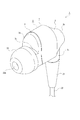
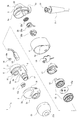
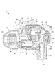
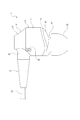
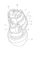
- FIGS. 2 to 8 show an embodiment of an acoustic output device according to the present technology, and this figure is a perspective view of the acoustic output device. It is an exploded perspective view of a sound output device. It is an expanded sectional view of a sound output device. It is an enlarged side view of a sound output device. It is an enlarged rear view showing a bracket and a cap. It is an expansion perspective view showing a part of internal structure, etc.
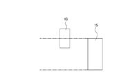
- FIG. 6 is a side view showing an example in which a part of the detection microphone is positioned to face the speaker. It is a side view which shows the example which a detection microphone is not located facing the speaker.
- the embodiment described below is an application of the present technology acoustic output device to an earphone.
- the scope of application of the present technology is not limited to earphones, and can be widely applied to various other sound output devices such as headphones.
- the sound output device shown below is provided with a speaker and an audio output unit as an audio output unit, and is provided with a sound conduit through which the audio output from the speaker and the audio output unit passes, respectively.
- the axial direction of the sound conduit is the front and back direction
- the arrangement direction of the speakers and the audio output device is the up and down direction to indicate the front, back, left, right, upper and lower directions.
- the configuration of the sound output device 1 will be described below (see FIGS. 1 to 6).
- the sound output device 1 is used, for example, as a pair, one for left ear and the other for right ear. However, listening to voice may be performed using one sound output device 1.
- the sound output device 1 has necessary parts disposed inside and outside the housing 2, and the housing 2 is formed by connecting the front cover 3, the middle cover 4 and the rear cover 5 in order from the front (see FIGS. 1 to 3).
- the front cover 3 includes a substantially hook-like cover surface 3a opened rearward, a coupling surface 3b projecting rearward from a portion near the outer periphery of the cover surface 3a, and a holding cylinder 3c projecting forward from the cover surface 3a.
- the coupling surface portion 3b is formed in a substantially arc-like surface shape, and protrudes rearward from a portion other than the lower end portion in a portion near the outer periphery of the cover surface portion 3a.
- the middle cover 4 is formed in a cylindrical shape in which the axial direction is in the front-rear direction, and the size and shape of the outer shape are substantially the same as the size and shape of the outer shape of the cover portion 3a.
- a vent 4a is formed at the lower end of the middle cover 4 (see FIG. 4).
- the rear cover 5 has a rear surface 5a, a circumferential surface 5b, a coupling surface 5c, an insertion cylinder 5d, and a mounting cylinder 5e (see FIGS. 1 to 3).
- the rear surface portion 5a is formed in an annular shape whose axial direction is the front-rear direction. An inner space of the rear surface portion 5a is formed as an opening 5f.
- the peripheral surface portion 5b is protruded forward from the outer peripheral portion of the rear surface portion 5a, and is formed in a shape whose outer shape becomes larger as it goes forward.
- the coupling surface portion 5c is projected forward from a portion of the front end portion of the circumferential surface portion 5b excluding the lower end portion.
- the insertion cylindrical portion 5d is formed in a cylindrical shape which protrudes downward from the lower end portion of the circumferential surface portion 5b.
- the mounting cylindrical portion 5e is formed in a cylindrical shape projecting forward from the rear surface portion 5a.
- the housing 2 is configured such that the front end of the middle cover 4 is externally fitted to the coupling surface 3b of the front cover 3 and the rear end of the middle cover 4 is externally coupled to the coupling surface 5c of the rear cover 5 Be done.
- a bracket 6 is disposed in the housing 2, and a part of the bracket 6 is projected forward from the holding cylinder 3c.
- the bracket 6 has a first mounting portion 7, a second mounting portion 8 and a sound conduit 9.
- the first mounting portion 7 has a substantially disk-shaped base surface portion 10 facing in the front-rear direction, and a cylindrical surface portion 11 projecting rearward from the outer peripheral portion of the base surface portion 10.
- a voice input hole 10a, an adjustment hole 10b, and a first voice passage hole 10c are formed in the base surface portion 10 sequentially from the upper side (see FIG. 5).
- the second mounting portion 8 is formed in the shape of a case that extends in the front-rear direction and is opened to the rear, is positioned below the first mounting portion 7, and the substantially rear half portion is continued to the first mounting portion 7 ( 2, 3 and 5).
- the second attachment portion 8 is formed with a second sound passage hole 8a which is vertically penetrated in the front half portion of the upper surface portion.
- the sound conduit 9 has a substantially cylindrical sound guide cylinder 9a whose axial direction is the front-rear direction, and a partition plate 9b located inside the sound guide cylinder 9a.
- the sound conduit 9 protrudes forward from the lower end of the base surface 10, and the substantially rear half portion is continued to the substantially front half of the second mounting portion 8.
- a first sound passage hole 10c of the base surface portion 10 and a second sound passage hole 8a of the second attachment portion 8 are in communication with an internal space of the sound guide tube portion 9a.
- the partition plate portion 9b is directed vertically and protrudes forward from the lower opening edge of the first sound passage hole 10c formed in the base surface portion 10, and the left and right side edges are respectively continued to the inner surface of the sound guide tube portion 9a. ing. Accordingly, a part of the internal space of the sound conduit 9 is partitioned at the upper and lower sides by the partition plate portion 9 b.
- a portion of the bracket 6 other than the front end portion of the sound conduit 9 is disposed inside the housing 2, and the sound guiding cylindrical portion 9 a is held in a state of being inserted into the holding cylindrical portion 3 c of the front cover 3.
- the front end portion of the sound guide cylinder 9a of the bracket 6 is projected forward from the holding cylinder 3c.
- An equalizer 12 is disposed at a front end portion of the sound guide tube portion 9a in a state of being press-fitted.
- the equalizer 12 is formed of, for example, compressed urethane, and has a function of adjusting mainly the degree of attenuation of the high region in the sound passing through the sound guide tube portion 9a.
- a detection microphone 13, a register 14 and a speaker 15 are attached to the first attachment portion 7 of the bracket 6.
- the detection microphone 13 functions as a feedback microphone that detects noise at a position close to the ear, and is attached to the front surface of the base surface 10 at a position covering the voice input hole 10 a.
- the detection microphone 13 is provided with an input diaphragm 13a whose outer shape is formed in a circular shape and which is directed substantially in the front-rear direction.
- the resistor 14 is, for example, formed in an annular shape, and is attached to the rear surface of the base surface portion 10 in a state where the central hole 14a is positioned directly behind the adjustment hole 10b.
- the register 14 mainly has a function of adjusting the sensitivity of the low frequency band of the sound output from the speaker 15.
- the central hole 14 a of the register 14 is smaller in diameter than the adjustment hole 10 b of the base surface portion 10.
- the speaker 15 is attached to the bracket 6 in a state in which the front portion is inserted into the first attachment portion 7.
- the speaker 15 is provided with an output diaphragm 15a whose outer shape is formed in a circular shape and which is directed substantially in the front-rear direction.
- the detection microphone 13 is attached to the front surface of the base surface 10 and the speaker 15 is attached to the rear surface of the base surface 10, and the detection microphone 13 is positioned directly in front of the speaker 15. Therefore, the detection microphone 13 is positioned facing the speaker 15 as a whole.
- the input diaphragm 13a of the detection microphone 13 and the output diaphragm 15a of the speaker 15 are both directed substantially in the front-rear direction and in substantially the same direction.
- the speaker 15 is capable of outputting a wide band of audio from low to high frequencies.
- the distance between the detection microphone 13 and the speaker 15 is less than or equal to the radius of the detection microphone 13.
- the radius of the detection microphone 13 is 2 mm
- the distance between the detection microphone 13 and the speaker 15 is 1 mm or less.
- the axial direction of the detection microphone 13 (central axis S1 direction) and the axial direction of the speaker 15 (central axis S2 direction) are both forward and backward, and the axial direction of the detection microphone 13 and the axial direction of the speaker 15 are substantially It is made the same.
- a sound absorbing material 16 is attached to the rear surface of the speaker 15.
- the sound absorbing material 16 is formed of, for example, compressed urethane, and mainly has a function of adjusting the sensitivity of the middle to low range of the sound output from the speaker 15.
- Arrangement holes 17 a are formed in the speaker cover 17.
- the speaker cover 17 is attached from the rear to the first attachment portion 7 of the bracket 6 and covers the speaker 15 from the rear.
- the sound absorbing material 16 is arranged in the arrangement hole 17 a.
- An audio output device 18 is attached to the second attachment portion 8 of the bracket 6.
- the microphone unit 20 is located behind the speaker 15.
- the audio output device 18 is disposed in the second attachment portion 18 in a state of being inserted from the rear.
- the sound output unit 18 functions as, for example, a tweeter, and outputs high-range sound that is sound in a frequency band different from the frequency band of the sound output from the speaker 15.
- a substrate 19 is attached to the rear surface of the speaker cover 17. Driving control of the speaker 15 and the audio output device 18 is performed by the substrate 19.
- a microphone unit 20 is attached to the mounting cylinder 5 e of the rear cover 5.
- the microphone unit 20 includes a sensing microphone 20a, a microphone case 20b, and a microphone sheet 20c.
- the sensing microphone 20a is covered from the front by the microphone case 20b, and the microphone sheet 20c is attached to the rear surface of the sensing microphone 20a.
- the sensing microphone 20b is attached to the mounting cylinder 5e inside the housing 2, and functions as a feedforward microphone that detects noise input from the opening 5f at a position on the outer peripheral side of the sound output device 1.
- the bushing 21 is inserted into and attached to the insertion cylindrical portion 5 d of the rear cover 5.
- a cable 22 is coated on the bushing 21, and the cable 22 is connected to the substrate 19, the detection microphone 13 and the sensing microphone 20 a.
- a cap 23 is attached to a portion of the sound conduit 9 which is projected forward from the holding cylindrical portion 3 c of the front cover 3.
- the cap 23 is formed of a rubber material or the like, and is a portion inserted into the ear canal when the user uses the sound output device 1.
- the cap 23 is formed with a passage hole 23 a communicated with the internal space of the sound conduit 9.
- the sensing microphone 20 a is disposed inside the housing 2, and the detection microphone 13 and the sensing microphone 20 a are positioned on the opposite side of the speaker 15.
- the acoustic output device 1 can be miniaturized by effectively utilizing the space.
- a bracket 6 having a sound conduit 9 through which the sound output from the speaker 15 passes is provided, and the speaker 15 and the detection microphone 13 are attached to the bracket 6.
- the audio output unit 18 is attached to the bracket 6, the speaker 15, the detection microphone 13 and the audio output unit 18 are all attached to the same member, and the speaker 15, the detection microphone 13 and the audio output unit 18 are attached. It is possible to further miniaturize the sound output device 1 by reducing the number of parts without requiring a dedicated member for the purpose.
- the voice output unit 18 also outputs voice, and the output voice passes from the second voice passage hole 8 a of the second mounting portion 8 to the inside of the sound conduit 9. At this time, the voice passes through the lower side of the partition plate portion 9a inside the sound conduit 9, and reaches the tympanic membrane of the user through the passage hole 23a of the cap 23.
- the sound output from the speaker 15 and the sound output unit 18 and passing through the inside of the sound conduit 9 is adjusted in the high frequency attenuation degree by the equalizer 12 and the sound whose high frequency is properly adjusted reaches the eardrum.
- the sound output from the sound output unit 18 is configured to pass through the sound conduit 9.
- both the audio output from the speaker 15 and the audio output from the audio output unit 18 are output to the outside through the sound conduit 9, the audio output from the speaker 15 and output from the audio output unit 18 It is possible to reduce the size of the sound output device 1 and reduce the manufacturing cost by reducing the number of parts without requiring separate sound conduits respectively passing through the voices.
- the output sound is also input to the detection microphone 13 from the sound input hole 10 a of the base surface 10 in addition to passing through the sound conduit 9.
- the sound outputted from the speaker 15 passes through the center hole 14 a of the register 14 through the adjustment hole 10 b of the base surface portion 10.
- the low-pass sensitivity is adjusted by the register 14.
- the sound that has passed through the center hole 14 a of the register 14 is guided downward through the inner surface side of the front cover 3 and emitted from the vent hole 4 a of the middle cover 4 to the outside.
- the sound when a sound is output from the speaker 15, the sound is also output to the rear, and the sensitivity of the mid-low range is adjusted by the sound absorbing material 16.
- the sound output rearward from the speaker 15 is at least partially guided downward, and is emitted to the outside from the vent 4 a of the middle cover 4.
- the noise canceling function is executed by the detection microphone 13 and the sensing microphone 20a.
- noise in the sound passing through the inside of the sound conduit 9 is mainly detected by the detection microphone 13 and noise in the external sound is detected by the sensing microphone 20a, and each detected noise is minimized.
- a noise canceling signal that causes the user to perceive is generated by a noise canceling circuit (not shown).
- the generation of the noise canceling signal causes the noise detected by the detection microphone 13 and the sensing microphone 20a to be canceled so that the high quality sound with the noise minimized is heard. Be done.
- the detection microphone 13 having the input diaphragm 13a for detecting noise
- the speaker 15 having the output diaphragm 15a
- the housing 2 in which the microphone 13 is disposed is provided, and the directions of the input diaphragm 13a and the output diaphragm 15a are substantially the same.
- the input diaphragm 13a and the output diaphragm 15a facing each other, the output of the sound from the speaker 15 and the input of the sound to the detection microphone 13 are performed, and the distance between the input diaphragm and the output diaphragm is Since it becomes possible to make the delay close to the phase between the voice output from the speaker 15 and the voice input to the detection microphone 13, noise detection accuracy by the detection microphone 13 is improved, and noise cancellation is performed.
- the ring function can be improved.
- the axial direction of the speaker 15 and the axial direction of the detection microphone 13 are substantially the same.
- the output of the sound from the speaker 15 and the input of the sound to the detection microphone 13 are performed. Since it becomes possible to reduce the distance and it is difficult to cause a phase delay between the sound output from the speaker 15 and the sound input to the detection microphone 13, the detection accuracy of noise by the detection microphone 13 is enhanced. A high noise canceling function can be secured.
- the entire detection microphone 13 is positioned to face the speaker 15, the entire detection microphone 13 is positioned to face the speaker 15, and a higher noise canceling function can be ensured.
- the distance between the detection microphone 13 and the speaker 15 is smaller than the radius of the detection microphone 13 and the distance between the detection microphone 13 and the speaker 15 is small, the sound output from the speaker 15 is input to the detection microphone 13 A phase delay with voice is less likely to occur and a higher noise canceling function can be ensured.
- the sensing microphone 20a for detecting the noise input from the opening 5f of the housing 2 since the sensing microphone 20a for detecting the noise input from the opening 5f of the housing 2 is provided, the noise is also detected by the sensing microphone 20a in addition to the detection microphone 13 and the noise reduction characteristic is enhanced. Sound quality in the sound output device 1 can be improved.
- the directions of the input diaphragm 13a of the detection microphone 13 and the output diaphragm 15a of the speaker 15 are made substantially the same, and noise detection accuracy by the detection microphone 13 is enhanced. We are working to improve the noise canceling function.
- an audio output unit 18 which outputs audio in a frequency band different from the frequency band of the audio output from the speaker 15.
- the audio output unit 18 since the audio output unit 18 outputs high-range audio, for example, the audio output unit 18 may have a possibility that the output performance of high-range audio output from the speaker 15 may be degraded.
- the user By outputting the high frequency sound from the above, it is possible for the user to listen to good voice in a wide band from the high frequency to the low frequency.
- the sound output device 1 since the sound output unit 18 that outputs the sound in the frequency band different from the frequency band of the sound output from the speaker 15 is provided, the sound output device 1 When the output performance of a part of the bands is degraded, it is possible to output the voice of the band whose output performance is degraded from the voice output unit 18, and it is possible to output the voice of a wide band.
- the entire detection microphone 13 is not positioned facing the speaker 15. It is also possible (see FIG. 8).
- the axial direction of the speaker 15 and the axial direction of the detection microphone 13 are substantially the same, it is possible to have a configuration in which the entire detection microphone 13 is not positioned facing the speaker 15.
- the directions of the input diaphragm 13a of the detection microphone 13 and the output diaphragm 15a of the speaker 15 are substantially the same, or the axial direction of the speaker 15 and the axial direction of the detection microphone 13 are substantially the same. Since it is hard to produce the phase delay between the audio
- the present technology can be configured as follows.
- a detection microphone which has an input diaphragm and detects noise
- a speaker having an output diaphragm,
- a housing in which at least the speaker and the detection microphone are disposed;
- An acoustic output device in which the directions of the input diaphragm and the output diaphragm are substantially the same.
- the audio output device further including: an audio output unit that outputs audio in a frequency band different from a frequency band of audio output from the speaker.
- An opening is formed in the housing,
- the sound output device according to any one of (1) to (5), further including a sensing microphone that detects noise input from the opening.
- the sensing microphone is disposed inside the housing, The sound output device according to (6), wherein the detection microphone and the sensing microphone are positioned on opposite sides of the speaker.
- a bracket having a sound conduit through which the sound output from the speaker is passed;
- the sound output device according to any one of (1) to (7), wherein the speaker and the detection microphone are attached to the bracket.
- An audio output unit is provided that outputs audio in a frequency band different from the frequency band of the audio output from the speaker,
- a detection microphone which has an input diaphragm and detects noise;
- a speaker having an output diaphragm,
- a housing in which at least the speaker and the detection microphone are disposed;
- An acoustic output device wherein an axial direction of the speaker and an axial direction of the detection microphone are substantially the same.
Landscapes
- Engineering & Computer Science (AREA)
- Physics & Mathematics (AREA)
- Acoustics & Sound (AREA)
- Signal Processing (AREA)
- Manufacturing & Machinery (AREA)
- Health & Medical Sciences (AREA)
- Audiology, Speech & Language Pathology (AREA)
- General Health & Medical Sciences (AREA)
- Multimedia (AREA)
- Soundproofing, Sound Blocking, And Sound Damping (AREA)
- Circuit For Audible Band Transducer (AREA)
- Headphones And Earphones (AREA)
Abstract
Description
以下に、音響出力装置1の構成について説明する(図1乃至図6参照)。音響出力装置1は、例えば、一対で使用され、一方が左耳用として使用され他方が右耳用として使用される。但し、一つの音響出力装置1を使用して音声の聞き取りが行われてもよい。
上記のように構成された音響出力装置1において、スピーカー15から音声が出力されると、出力された音声はベース面部10の第1の音声通過孔10cから音導管9の内部を通る。このとき音声は音導管9の内部において仕切板部9aの上側を通り、キャップ23の通過孔23aを介して使用者の鼓膜に到達する。
以上に記載した通り、音響出力装置1にあっては、入力用振動板13aを有しノイズを検出する検出マイク13と、出力用振動板15aを有するスピーカー15と、内部に少なくともスピーカー15と検出マイク13が配置されたハウジング2とが設けられ、入力用振動板13aと出力用振動板15aの向きが略同じにされている。
上記には、検出マイク13の全体がスピーカー15に対向して位置された例を示したが、音響出力装置1においては、検出マイク13の一部がスピーカー15に対向して位置されていてもよい(図7参照)。
本技術は、以下のような構成にすることができる。
入力用振動板を有しノイズを検出する検出マイクと、
出力用振動板を有するスピーカーと、
内部に少なくとも前記スピーカーと前記検出マイクが配置されたハウジングとを備え、
前記入力用振動板と前記出力用振動板の向きが略同じにされた
音響出力装置。
前記検出マイクの少なくとも一部が前記スピーカーに対向して位置された
前記(1)に記載の音響出力装置。
前記検出マイクの全体が前記スピーカーに対向して位置された
前記(2)に記載の音響出力装置。
前記検出マイクと前記スピーカーの距離が前記検出マイクの半径以下にされた
前記(1)から前記(3)の何れかに記載の音響出力装置。
前記スピーカーから出力される音声の周波数帯域と異なる周波数帯域の音声を出力する音声出力器が設けられた
前記(1)から前記(4)の何れかに記載の音響出力装置。
前記ハウジングに開口が形成され、
前記開口から入力されるノイズを検出するセンシングマイクが設けられた
前記(1)から前記(5)の何れかに記載の音響出力装置。
前記センシングマイクが前記ハウジングの内部に配置され、
前記検出マイクと前記センシングマイクが前記スピーカーを挟んで反対側に位置された
前記(6)に記載の音響出力装置。
前記スピーカーから出力される音声が通過される音導管を有するブラケットが設けられ、
前記ブラケットに前記スピーカーと前記検出マイクが取り付けられた
前記(1)から前記(7)の何れかに記載の音響出力装置。
前記スピーカーから出力される音声の周波数帯域と異なる周波数帯域の音声を出力する音声出力器が設けられ、
前記音声出力器が前記ブラケットに取り付けられた
前記(8)に記載の音響出力装置。
前記音声出力器から出力される音声が前記音導管を通るようにされた
前記(9)に記載の音響出力装置。
入力用振動板を有しノイズを検出する検出マイクと、
出力用振動板を有するスピーカーと、
内部に少なくとも前記スピーカーと前記検出マイクが配置されたハウジングとを備え、
前記スピーカーの軸方向と前記検出マイクの軸方向とが略同じにされた
音響出力装置。
Claims (11)
- 入力用振動板を有しノイズを検出する検出マイクと、
出力用振動板を有するスピーカーと、
内部に少なくとも前記スピーカーと前記検出マイクが配置されたハウジングとを備え、
前記入力用振動板と前記出力用振動板の向きが略同じにされた
音響出力装置。 - 前記検出マイクの少なくとも一部が前記スピーカーに対向して位置された
請求項1に記載の音響出力装置。 - 前記検出マイクの全体が前記スピーカーに対向して位置された
請求項2に記載の音響出力装置。 - 前記検出マイクと前記スピーカーの距離が前記検出マイクの半径以下にされた
請求項1に記載の音響出力装置。 - 前記スピーカーから出力される音声の周波数帯域と異なる周波数帯域の音声を出力する音声出力器が設けられた
請求項1に記載の音響出力装置。 - 前記ハウジングに開口が形成され、
前記開口から入力されるノイズを検出するセンシングマイクが設けられた
請求項1に記載の音響出力装置。 - 前記センシングマイクが前記ハウジングの内部に配置され、
前記検出マイクと前記センシングマイクが前記スピーカーを挟んで反対側に位置された
請求項6に記載の音響出力装置。 - 前記スピーカーから出力される音声が通過される音導管を有するブラケットが設けられ、
前記ブラケットに前記スピーカーと前記検出マイクが取り付けられた
請求項1に記載の音響出力装置。 - 前記スピーカーから出力される音声の周波数帯域と異なる周波数帯域の音声を出力する音声出力器が設けられ、
前記音声出力器が前記ブラケットに取り付けられた
請求項8に記載の音響出力装置。 - 前記音声出力器から出力される音声が前記音導管を通るようにされた
請求項9に記載の音響出力装置。 - 入力用振動板を有しノイズを検出する検出マイクと、
出力用振動板を有するスピーカーと、
内部に少なくとも前記スピーカーと前記検出マイクが配置されたハウジングとを備え、
前記スピーカーの軸方向と前記検出マイクの軸方向とが略同じにされた
音響出力装置。
Priority Applications (4)
| Application Number | Priority Date | Filing Date | Title |
|---|---|---|---|
| US16/637,394 US11386880B2 (en) | 2017-08-17 | 2018-07-17 | Acoustic output apparatus |
| EP18847131.2A EP3672273A4 (en) | 2017-08-17 | 2018-07-17 | SOUND OUTPUT DEVICE |
| JP2019536446A JP7264052B2 (ja) | 2017-08-17 | 2018-07-17 | 音響出力装置 |
| CN201880051340.3A CN111034216B (zh) | 2017-08-17 | 2018-07-17 | 音响输出设备 |
Applications Claiming Priority (2)
| Application Number | Priority Date | Filing Date | Title |
|---|---|---|---|
| JP2017157640 | 2017-08-17 | ||
| JP2017-157640 | 2017-08-17 |
Publications (1)
| Publication Number | Publication Date |
|---|---|
| WO2019035304A1 true WO2019035304A1 (ja) | 2019-02-21 |
Family
ID=65362332
Family Applications (1)
| Application Number | Title | Priority Date | Filing Date |
|---|---|---|---|
| PCT/JP2018/026734 Ceased WO2019035304A1 (ja) | 2017-08-17 | 2018-07-17 | 音響出力装置 |
Country Status (5)
| Country | Link |
|---|---|
| US (1) | US11386880B2 (ja) |
| EP (1) | EP3672273A4 (ja) |
| JP (1) | JP7264052B2 (ja) |
| CN (1) | CN111034216B (ja) |
| WO (1) | WO2019035304A1 (ja) |
Cited By (2)
| Publication number | Priority date | Publication date | Assignee | Title |
|---|---|---|---|---|
| WO2020255596A1 (ja) * | 2019-06-21 | 2020-12-24 | ソニー株式会社 | 音響出力装置 |
| JP2021197672A (ja) * | 2020-06-17 | 2021-12-27 | ホシデン株式会社 | イヤホン |
Families Citing this family (4)
| Publication number | Priority date | Publication date | Assignee | Title |
|---|---|---|---|---|
| CN114666696B (zh) * | 2020-12-23 | 2023-06-06 | 华为技术有限公司 | 无线降噪耳机 |
| EP4102856B1 (en) | 2021-04-23 | 2026-02-11 | Samsung Electronics Co., Ltd. | Wearable electronic device comprising speakers and a microphone |
| KR102935346B1 (ko) * | 2021-08-06 | 2026-03-09 | 엘지전자 주식회사 | 휴대용 음향기기 |
| EP4529217A4 (en) * | 2023-01-30 | 2025-08-06 | Shenzhen Shokz Co Ltd | MOTION MODULE AND ELECTRONIC DEVICE |
Citations (4)
| Publication number | Priority date | Publication date | Assignee | Title |
|---|---|---|---|---|
| JP2010157787A (ja) * | 2008-12-26 | 2010-07-15 | Victor Co Of Japan Ltd | ヘッドホン |
| JP2012085257A (ja) * | 2010-10-06 | 2012-04-26 | Cotron Corp | イヤホン |
| JP2013526798A (ja) * | 2010-05-14 | 2013-06-24 | クリエイティブ、テクノロジー、リミテッド | モニタ機能を有するノイズリダクション回路 |
| JP2017034702A (ja) | 2016-09-30 | 2017-02-09 | ソニー株式会社 | イヤホン装置 |
Family Cites Families (13)
| Publication number | Priority date | Publication date | Assignee | Title |
|---|---|---|---|---|
| JPH05333873A (ja) * | 1992-05-29 | 1993-12-17 | Sony Corp | 雑音低減装置 |
| US5692059A (en) | 1995-02-24 | 1997-11-25 | Kruger; Frederick M. | Two active element in-the-ear microphone system |
| US7466838B1 (en) * | 2003-12-10 | 2008-12-16 | William T. Moseley | Electroacoustic devices with noise-reducing capability |
| JP4850524B2 (ja) | 2006-01-27 | 2012-01-11 | ナップエンタープライズ株式会社 | 発振・エコーキャンセラーシステム |
| JP2009284097A (ja) | 2008-05-20 | 2009-12-03 | Toshiba Corp | カナル型イヤホンおよびその使用方法ならびに共鳴周波数算出装置 |
| WO2012042672A1 (ja) | 2010-10-01 | 2012-04-05 | フォスター電機株式会社 | ノイズキャンセルヘッドホン |
| CN103460714B (zh) * | 2011-01-28 | 2016-08-31 | 海宝拉株式会社 | 耳内传声器及耳内传声器用电压控制装置 |
| US9058801B2 (en) * | 2012-09-09 | 2015-06-16 | Apple Inc. | Robust process for managing filter coefficients in adaptive noise canceling systems |
| US9055366B2 (en) * | 2013-01-22 | 2015-06-09 | Apple Inc. | Multi-driver earbud |
| CN105745119B (zh) * | 2013-11-19 | 2020-05-12 | 歌乐株式会社 | 头枕装置以及声音采集装置 |
| KR101693268B1 (ko) | 2015-04-10 | 2017-01-05 | 해보라 주식회사 | 이어셋 |
| US9613615B2 (en) | 2015-06-22 | 2017-04-04 | Sony Corporation | Noise cancellation system, headset and electronic device |
| JPWO2017126257A1 (ja) * | 2016-01-19 | 2018-10-04 | 富士フイルム株式会社 | 電気音響変換器 |
-
2018
- 2018-07-17 WO PCT/JP2018/026734 patent/WO2019035304A1/ja not_active Ceased
- 2018-07-17 JP JP2019536446A patent/JP7264052B2/ja active Active
- 2018-07-17 US US16/637,394 patent/US11386880B2/en active Active
- 2018-07-17 EP EP18847131.2A patent/EP3672273A4/en not_active Ceased
- 2018-07-17 CN CN201880051340.3A patent/CN111034216B/zh active Active
Patent Citations (4)
| Publication number | Priority date | Publication date | Assignee | Title |
|---|---|---|---|---|
| JP2010157787A (ja) * | 2008-12-26 | 2010-07-15 | Victor Co Of Japan Ltd | ヘッドホン |
| JP2013526798A (ja) * | 2010-05-14 | 2013-06-24 | クリエイティブ、テクノロジー、リミテッド | モニタ機能を有するノイズリダクション回路 |
| JP2012085257A (ja) * | 2010-10-06 | 2012-04-26 | Cotron Corp | イヤホン |
| JP2017034702A (ja) | 2016-09-30 | 2017-02-09 | ソニー株式会社 | イヤホン装置 |
Non-Patent Citations (1)
| Title |
|---|
| See also references of EP3672273A4 |
Cited By (6)
| Publication number | Priority date | Publication date | Assignee | Title |
|---|---|---|---|---|
| WO2020255596A1 (ja) * | 2019-06-21 | 2020-12-24 | ソニー株式会社 | 音響出力装置 |
| CN113994710A (zh) * | 2019-06-21 | 2022-01-28 | 索尼集团公司 | 声音输出设备 |
| US11895459B2 (en) | 2019-06-21 | 2024-02-06 | Sony Group Corporation | Sound output device |
| JP7509141B2 (ja) | 2019-06-21 | 2024-07-02 | ソニーグループ株式会社 | 音響出力装置 |
| JP2021197672A (ja) * | 2020-06-17 | 2021-12-27 | ホシデン株式会社 | イヤホン |
| JP7437244B2 (ja) | 2020-06-17 | 2024-02-22 | ホシデン株式会社 | イヤホン |
Also Published As
| Publication number | Publication date |
|---|---|
| JP7264052B2 (ja) | 2023-04-25 |
| US20200251086A1 (en) | 2020-08-06 |
| JPWO2019035304A1 (ja) | 2020-07-27 |
| EP3672273A1 (en) | 2020-06-24 |
| US11386880B2 (en) | 2022-07-12 |
| CN111034216B (zh) | 2022-07-01 |
| EP3672273A4 (en) | 2020-08-26 |
| CN111034216A (zh) | 2020-04-17 |
Similar Documents
| Publication | Publication Date | Title |
|---|---|---|
| US11057695B2 (en) | In-ear headphone device with active noise control | |
| JP7264052B2 (ja) | 音響出力装置 | |
| US10149034B2 (en) | Earphone | |
| JP5363825B2 (ja) | ノイズキャンセルヘッドホン | |
| JP6380504B2 (ja) | ヘッドホン | |
| USRE48424E1 (en) | Custom fit in-ear monitors utilizing a single piece driver module | |
| US9613614B2 (en) | Noise-reducing headphone | |
| US8744112B2 (en) | Earphone with speaker facing away from earpiece and sound tube that communicates with spaces in front of and behind the speaker | |
| EP3200476B1 (en) | Headphone | |
| WO2013108370A1 (ja) | ヘッドホン | |
| JP5872722B1 (ja) | 連通管付きイヤホン | |
| EP3396975B1 (en) | Headphones | |
| JP7383165B2 (ja) | 向上した風ノイズ抵抗性を有するワイヤレスヘッドセット | |
| TWI688279B (zh) | 耳機揚聲器構造 | |
| JP2019121896A (ja) | 首掛け型スピーカー装置 | |
| JP2019121897A (ja) | 首掛け型スピーカー装置 | |
| JP2019145965A (ja) | イヤホン | |
| JP6583226B2 (ja) | ヘッドホン | |
| US11979707B1 (en) | System and method for an audio reproduction device | |
| JP2016201786A (ja) | 連通管付きイヤホン | |
| JP2019029900A (ja) | 首掛け型スピーカー装置 |
Legal Events
| Date | Code | Title | Description |
|---|---|---|---|
| 121 | Ep: the epo has been informed by wipo that ep was designated in this application |
Ref document number: 18847131 Country of ref document: EP Kind code of ref document: A1 |
|
| ENP | Entry into the national phase |
Ref document number: 2019536446 Country of ref document: JP Kind code of ref document: A |
|
| NENP | Non-entry into the national phase |
Ref country code: DE |
|
| ENP | Entry into the national phase |
Ref document number: 2018847131 Country of ref document: EP Effective date: 20200317 |
|
| WWW | Wipo information: withdrawn in national office |
Ref document number: 2018847131 Country of ref document: EP |