WO2019039406A1 - 車室内構造 - Google Patents
車室内構造 Download PDFInfo
- Publication number
- WO2019039406A1 WO2019039406A1 PCT/JP2018/030553 JP2018030553W WO2019039406A1 WO 2019039406 A1 WO2019039406 A1 WO 2019039406A1 JP 2018030553 W JP2018030553 W JP 2018030553W WO 2019039406 A1 WO2019039406 A1 WO 2019039406A1
- Authority
- WO
- WIPO (PCT)
- Prior art keywords
- driver
- vehicle interior
- vehicle
- vanishing point
- interior structure
- Prior art date
- Legal status (The legal status is an assumption and is not a legal conclusion. Google has not performed a legal analysis and makes no representation as to the accuracy of the status listed.)
- Ceased
Links
Images


Classifications
-
- B—PERFORMING OPERATIONS; TRANSPORTING
- B60—VEHICLES IN GENERAL
- B60J—WINDOWS, WINDSCREENS, NON-FIXED ROOFS, DOORS, OR SIMILAR DEVICES FOR VEHICLES; REMOVABLE EXTERNAL PROTECTIVE COVERINGS SPECIALLY ADAPTED FOR VEHICLES
- B60J1/00—Windows; Windscreens; Accessories therefor
- B60J1/02—Windows; Windscreens; Accessories therefor arranged at the vehicle front, e.g. structure of the glazing, mounting of the glazing
-
- B—PERFORMING OPERATIONS; TRANSPORTING
- B60—VEHICLES IN GENERAL
- B60J—WINDOWS, WINDSCREENS, NON-FIXED ROOFS, DOORS, OR SIMILAR DEVICES FOR VEHICLES; REMOVABLE EXTERNAL PROTECTIVE COVERINGS SPECIALLY ADAPTED FOR VEHICLES
- B60J5/00—Doors
- B60J5/04—Doors arranged at the vehicle sides
-
- B—PERFORMING OPERATIONS; TRANSPORTING
- B60—VEHICLES IN GENERAL
- B60K—ARRANGEMENT OR MOUNTING OF PROPULSION UNITS OR OF TRANSMISSIONS IN VEHICLES; ARRANGEMENT OR MOUNTING OF PLURAL DIVERSE PRIME-MOVERS IN VEHICLES; AUXILIARY DRIVES FOR VEHICLES; INSTRUMENTATION OR DASHBOARDS FOR VEHICLES; ARRANGEMENTS IN CONNECTION WITH COOLING, AIR INTAKE, GAS EXHAUST OR FUEL SUPPLY OF PROPULSION UNITS IN VEHICLES
- B60K35/00—Instruments specially adapted for vehicles; Arrangement of instruments in or on vehicles
- B60K35/20—Output arrangements, i.e. from vehicle to user, associated with vehicle functions or specially adapted therefor
- B60K35/21—Output arrangements, i.e. from vehicle to user, associated with vehicle functions or specially adapted therefor using visual output, e.g. blinking lights or matrix displays
- B60K35/22—Display screens
-
- B—PERFORMING OPERATIONS; TRANSPORTING
- B60—VEHICLES IN GENERAL
- B60K—ARRANGEMENT OR MOUNTING OF PROPULSION UNITS OR OF TRANSMISSIONS IN VEHICLES; ARRANGEMENT OR MOUNTING OF PLURAL DIVERSE PRIME-MOVERS IN VEHICLES; AUXILIARY DRIVES FOR VEHICLES; INSTRUMENTATION OR DASHBOARDS FOR VEHICLES; ARRANGEMENTS IN CONNECTION WITH COOLING, AIR INTAKE, GAS EXHAUST OR FUEL SUPPLY OF PROPULSION UNITS IN VEHICLES
- B60K35/00—Instruments specially adapted for vehicles; Arrangement of instruments in or on vehicles
- B60K35/20—Output arrangements, i.e. from vehicle to user, associated with vehicle functions or specially adapted therefor
- B60K35/28—Output arrangements, i.e. from vehicle to user, associated with vehicle functions or specially adapted therefor characterised by the type of the output information, e.g. video entertainment or vehicle dynamics information; characterised by the purpose of the output information, e.g. for attracting the attention of the driver
- B60K35/285—Output arrangements, i.e. from vehicle to user, associated with vehicle functions or specially adapted therefor characterised by the type of the output information, e.g. video entertainment or vehicle dynamics information; characterised by the purpose of the output information, e.g. for attracting the attention of the driver for improving awareness by directing driver's gaze direction or eye points
-
- B—PERFORMING OPERATIONS; TRANSPORTING
- B60—VEHICLES IN GENERAL
- B60K—ARRANGEMENT OR MOUNTING OF PROPULSION UNITS OR OF TRANSMISSIONS IN VEHICLES; ARRANGEMENT OR MOUNTING OF PLURAL DIVERSE PRIME-MOVERS IN VEHICLES; AUXILIARY DRIVES FOR VEHICLES; INSTRUMENTATION OR DASHBOARDS FOR VEHICLES; ARRANGEMENTS IN CONNECTION WITH COOLING, AIR INTAKE, GAS EXHAUST OR FUEL SUPPLY OF PROPULSION UNITS IN VEHICLES
- B60K35/00—Instruments specially adapted for vehicles; Arrangement of instruments in or on vehicles
- B60K35/60—Instruments characterised by their location or relative disposition in or on vehicles
-
- B—PERFORMING OPERATIONS; TRANSPORTING
- B60—VEHICLES IN GENERAL
- B60K—ARRANGEMENT OR MOUNTING OF PROPULSION UNITS OR OF TRANSMISSIONS IN VEHICLES; ARRANGEMENT OR MOUNTING OF PLURAL DIVERSE PRIME-MOVERS IN VEHICLES; AUXILIARY DRIVES FOR VEHICLES; INSTRUMENTATION OR DASHBOARDS FOR VEHICLES; ARRANGEMENTS IN CONNECTION WITH COOLING, AIR INTAKE, GAS EXHAUST OR FUEL SUPPLY OF PROPULSION UNITS IN VEHICLES
- B60K37/00—Dashboards
- B60K37/20—Dashboard panels
-
- B—PERFORMING OPERATIONS; TRANSPORTING
- B60—VEHICLES IN GENERAL
- B60R—VEHICLES, VEHICLE FITTINGS, OR VEHICLE PARTS, NOT OTHERWISE PROVIDED FOR
- B60R13/00—Elements for body-finishing, identifying, or decorating; Arrangements or adaptations for advertising purposes
- B60R13/02—Internal Trim mouldings ; Internal Ledges; Wall liners for passenger compartments; Roof liners
- B60R13/0256—Dashboard liners
-
- B—PERFORMING OPERATIONS; TRANSPORTING
- B60—VEHICLES IN GENERAL
- B60K—ARRANGEMENT OR MOUNTING OF PROPULSION UNITS OR OF TRANSMISSIONS IN VEHICLES; ARRANGEMENT OR MOUNTING OF PLURAL DIVERSE PRIME-MOVERS IN VEHICLES; AUXILIARY DRIVES FOR VEHICLES; INSTRUMENTATION OR DASHBOARDS FOR VEHICLES; ARRANGEMENTS IN CONNECTION WITH COOLING, AIR INTAKE, GAS EXHAUST OR FUEL SUPPLY OF PROPULSION UNITS IN VEHICLES
- B60K2360/00—Indexing scheme associated with groups B60K35/00 or B60K37/00 relating to details of instruments or dashboards
- B60K2360/60—Structural details of dashboards or instruments
- B60K2360/68—Features of instruments
- B60K2360/688—Frames or decorative parts
-
- B—PERFORMING OPERATIONS; TRANSPORTING
- B60—VEHICLES IN GENERAL
- B60K—ARRANGEMENT OR MOUNTING OF PROPULSION UNITS OR OF TRANSMISSIONS IN VEHICLES; ARRANGEMENT OR MOUNTING OF PLURAL DIVERSE PRIME-MOVERS IN VEHICLES; AUXILIARY DRIVES FOR VEHICLES; INSTRUMENTATION OR DASHBOARDS FOR VEHICLES; ARRANGEMENTS IN CONNECTION WITH COOLING, AIR INTAKE, GAS EXHAUST OR FUEL SUPPLY OF PROPULSION UNITS IN VEHICLES
- B60K2360/00—Indexing scheme associated with groups B60K35/00 or B60K37/00 relating to details of instruments or dashboards
- B60K2360/60—Structural details of dashboards or instruments
- B60K2360/68—Features of instruments
- B60K2360/691—Housings
-
- B—PERFORMING OPERATIONS; TRANSPORTING
- B60—VEHICLES IN GENERAL
- B60K—ARRANGEMENT OR MOUNTING OF PROPULSION UNITS OR OF TRANSMISSIONS IN VEHICLES; ARRANGEMENT OR MOUNTING OF PLURAL DIVERSE PRIME-MOVERS IN VEHICLES; AUXILIARY DRIVES FOR VEHICLES; INSTRUMENTATION OR DASHBOARDS FOR VEHICLES; ARRANGEMENTS IN CONNECTION WITH COOLING, AIR INTAKE, GAS EXHAUST OR FUEL SUPPLY OF PROPULSION UNITS IN VEHICLES
- B60K2360/00—Indexing scheme associated with groups B60K35/00 or B60K37/00 relating to details of instruments or dashboards
- B60K2360/77—Instrument locations other than the dashboard
- B60K2360/774—Instrument locations other than the dashboard on or in the centre console
-
- B—PERFORMING OPERATIONS; TRANSPORTING
- B60—VEHICLES IN GENERAL
- B60K—ARRANGEMENT OR MOUNTING OF PROPULSION UNITS OR OF TRANSMISSIONS IN VEHICLES; ARRANGEMENT OR MOUNTING OF PLURAL DIVERSE PRIME-MOVERS IN VEHICLES; AUXILIARY DRIVES FOR VEHICLES; INSTRUMENTATION OR DASHBOARDS FOR VEHICLES; ARRANGEMENTS IN CONNECTION WITH COOLING, AIR INTAKE, GAS EXHAUST OR FUEL SUPPLY OF PROPULSION UNITS IN VEHICLES
- B60K2360/00—Indexing scheme associated with groups B60K35/00 or B60K37/00 relating to details of instruments or dashboards
- B60K2360/77—Instrument locations other than the dashboard
- B60K2360/782—Instrument locations other than the dashboard on the steering wheel
-
- B—PERFORMING OPERATIONS; TRANSPORTING
- B60—VEHICLES IN GENERAL
- B60K—ARRANGEMENT OR MOUNTING OF PROPULSION UNITS OR OF TRANSMISSIONS IN VEHICLES; ARRANGEMENT OR MOUNTING OF PLURAL DIVERSE PRIME-MOVERS IN VEHICLES; AUXILIARY DRIVES FOR VEHICLES; INSTRUMENTATION OR DASHBOARDS FOR VEHICLES; ARRANGEMENTS IN CONNECTION WITH COOLING, AIR INTAKE, GAS EXHAUST OR FUEL SUPPLY OF PROPULSION UNITS IN VEHICLES
- B60K2360/00—Indexing scheme associated with groups B60K35/00 or B60K37/00 relating to details of instruments or dashboards
- B60K2360/77—Instrument locations other than the dashboard
- B60K2360/785—Instrument locations other than the dashboard on or in relation to the windshield or windows
Definitions
- the present invention relates to the interior structure of a vehicle.
- Patent Document 1 JP-A-2015-217860 (Patent Document 1) describes a window frame structure of a car.
- a virtual edge which extends vertically and is visible by the driver is displayed.
- the imaginary edge is formed to be gradually separated from the lower part of the front pillar as it goes upward.
- the driver feels that the optical flow extending from the vanishing point is lost at the virtual edge, and from the driver's point of view, the front pillar is close to an upright body as viewed from the driver The same visual condition as in the condition is ensured. As a result, it is possible to improve the feeling of the vehicle speed felt by the driver.
- an object of the present invention is to provide a vehicle interior structure that allows the driver to easily grasp the position of the vehicle.
- the present invention is a vehicle interior structure of a vehicle, comprising a vehicle interior structure disposed in the driver's field of view, at least one contour of the vehicle interior structure Is characterized by substantially coinciding with an axis toward the vehicle compartment among axes extending radially from the vanishing point when the driver seated in the driver's seat visually recognizes the front.
- the driver When the driver is driving the vehicle, the driver may unintentionally cause the vehicle to travel to one side in the lane, or may meander in the lane. Or when trying to stop a vehicle according to a parting line in a parking lot, a vehicle can not be made to stop in parallel with a parting line, but parking may be repeated many times.
- the interior structure of the driving vehicle is also influenced. That is, even when the same driver is driving a certain vehicle, it is possible to easily drive the appropriate position in the lane, but when driving another vehicle, it is in the traveling lane. And meandering is likely to occur.
- At least one of the contour lines of the in-cabin structure has an axis radially extending from the vanishing point when the driver seated in the driver's seat visually recognizes the front, It substantially coincides with the axis toward the vehicle interior.
- the driver can appropriately imagine the virtual axis extending to his / her own foot, and can easily grasp his / her position in the space in which the vehicle travels. As a result, the driver can easily travel at an appropriate position in the traveling lane.
- At least one contour line of the vehicle interior structure is viewed so as to substantially coincide with the axis toward the vehicle compartment in the front view of the driver seated at the driver's seat.
- the outline of the vehicle interior structure and the axis from the vanishing point to the vehicle interior substantially match in the front view of the driver seated at the driver's seat,
- the axis which the driver imagines is hard to deviate from the actual axis, and the driver can easily travel at an appropriate position in the traveling lane.
- the vehicle interior structure is a window frame of the side window, and the lower edge of the window frame is configured to substantially coincide with the axis from the vanishing point toward the vehicle interior.
- the lower edge of the window frame of the side window is configured to substantially coincide with the axis from the vanishing point to the vehicle interior, so that the axis extending from the vanishing point;
- the contours of the structures substantially coincide at a relatively long distance, which can effectively assist the driver's "axis feeling".
- the vehicle interior structure is a center display disposed on an instrument panel of the vehicle, such that the edges on both sides of the center display substantially coincide with the axis from the vanishing point to the vehicle interior Is configured.
- the edges on both sides of the center display are configured to substantially coincide with the axis from the vanishing point toward the vehicle interior, so that the driver can see A contour that assists in "axis feeling” can be arranged, and the driver can obtain a more accurate axis feeling.
- the vehicle interior structure is a meter hood that covers the instruments of the vehicle, and a predetermined portion of the outer edge of the meter hood is configured to substantially coincide with the axis from the vanishing point to the vehicle interior .
- the predetermined portion of the outer edge of the meter hood is configured to substantially coincide with the axis from the vanishing point to the vehicle interior, the “axis "Feeling” is assisted, and the driver's "axial feeling” can be effectively enhanced.
- the instrument panel which is a vehicle interior structure, disposed in front of the driver's seat, the driver from the vanishing point when the driver seated in the driver's seat visually recognizes the front
- a vanishing point mark is provided which is arranged on the axis extending to it.
- the upper end portion of the instrument panel is provided with the vanishing point mark disposed on the axis extending to the driver from the vanishing point when the driver visually recognizes the front This makes it easier for the driver to recognize the vanishing point. This makes it easier for the driver to be aware of the axis extending from the vanishing point to himself, and the driver can easily grasp his position in the space where the vehicle travels, and easily travels at the appropriate position in the traveling lane. Can.
- the vanishing point mark provided at the upper end of the instrument panel is a projection provided on the instrument panel.
- the vanishing point mark is constituted by a projection provided on the instrument panel, the vanishing point mark can be fixed at a predetermined position without impairing the design of the vehicle interior structure. Can be provided.
- the projection provided on the instrument panel is provided on the top of the meter hood of the instrument panel.
- the protrusion serving as a mark of the vanishing point is located approximately at the center of the driver's field of vision. To position. As a result, the driver naturally turns to the projection and can effectively bring awareness to the axis extending from the vanishing point.
- the vanishing point mark provided at the upper end of the instrument panel is located above the upper end of the steering wheel of the vehicle, as viewed from the driver seated in the driver's seat of the vehicle.
- the vanishing point mark is located above the upper end of the steering wheel of the vehicle when viewed from the driver sitting on the driver's seat of the vehicle, so the vanishing point mark is a view outside the vehicle At the same time, the driver can always keep in the sight of the driver while driving, and can always promote awareness of the vanishing point.
- the driver can easily grasp the position of the own vehicle accurately.
- FIG. 1 is a view schematically showing a scene outside the vehicle viewed by a driver driving the vehicle.
- the driver grasps the position of the vehicle in the space where the vehicle travels while visually recognizing the scenery outside the vehicle while driving, and performs appropriate driving actions such as steering operation.
- the driver recognizes the position of the host vehicle in the space while recognizing the vanishing point P in a distant place and imaginary axis lines A1 to A8 radially extending from the vanishing point P unconsciously.
- the vanishing point P is a point on a distant horizon L, and as in the example shown in FIG. 1, when the vehicle travels in a straight lane with a constant width, the boundaries on both sides of the lane It is located at the intersection of axis A2 and axis A7 which coincides with the line.
- the virtual axis A extending from the vanishing point P is interrupted by the window frame W of the front window before reaching the driver's own foot. For this reason, the driver performs driving action while imaging in the head a virtual axis line extending out of the window frame W.
- the present inventor has found that the driver may become less aware of the axis extending from the vanishing point to the driver when the driver seated in the driver's seat views the front. Then, by arranging the vanishing point mark on the axis extending from the vanishing point to the driver, it has become clear that the line of sight of the driver is guided to the vanishing point and it becomes easier to be aware of the axis extending from the vanishing point.
- the driver who has seated at the driver's seat the axis toward the vehicle compartment and the outline of the vehicle interior structure among the axes extending radially from the vanishing point when the driver seated at the driver's seat visually recognizes the front
- the driver can easily visualize the axis extending outside the window frame W. That is, by making the axis extending from the vanishing point substantially coincide with the outline of the vehicle interior structure, the driver can easily obtain an "axial feeling" that is an image of the axis extending from the vanishing point to his own foot, and the vehicle It becomes possible to properly grasp the position of the vehicle in the space where it travels.
- FIG. 2 is a perspective view showing a passenger compartment structure according to the first embodiment of the present invention.
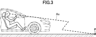
- FIG. 3 is a diagram showing the line of sight of the driver seated in the driver's seat.
- an instrument panel 2 a steering wheel 4, a meter 6, a front pillar 8, a front window 10, a side window 12, etc. Get into the driver's view.
- the instrument panel 2 is raised at a portion above the meter 6, and the raised portion constitutes a meter hood 14.
- the lower edge 12a of the window frame of the side window 12 on the driver's seat side which is a vehicle interior structure, is configured to substantially coincide with the axis Ab toward the vehicle interior from the vanishing point P. That is, the inclination of the lower edge 12a of the window frame of the side window 12 on the driver's seat side visually recognized by the driver sitting on the driver's seat substantially coincides with the inclination of the axis Ab toward the vehicle interior from the vanishing point P . In this manner, the driver can easily obtain an "axial feeling" by making the so-called “belt line” which is the lower edge 12a of the window frame of the side window 12 substantially coincide with the axis Ab directed from the vanishing point P to the vehicle interior. As a result, the position of the vehicle in the space where the vehicle travels can be accurately grasped.
- the instrument panel (dashboard) 2 is the highest at the portion of the meter hood 14. At the top of the center of the meter hood 14, the radius of curvature is reduced, and a protrusion 14a protruding upward is formed.
- the projection 14a is positioned on an axis Ac extending from the vanishing point when the driver seated in the driver's seat views the front, and functions as a vanishing point mark.
- the straight line connecting the projection 14a and the center point 4a of the steering wheel 4 is parallel to the longitudinal axis of the vehicle, and this straight line drives from the vanishing point when the driver visually recognizes the front Substantially coincides with the axis Ac extending to the subject.
- the projection 14a of the meter hood 14 provided at the upper end of the instrument panel 2 is located above the upper end 4b of the steering wheel 4 of the vehicle when viewed from the driver sitting in the driver's seat . Therefore, the protrusion 14a, which is the vanishing point mark, always enters the field of view of the driver while driving the vehicle, and the driver's attention is more strongly directed to the protrusion 14a.
- the line of sight of the driver is easily guided thereto.
- the driver's line of sight being guided by the protrusion 14a, the driver becomes strongly aware of the axis Ac extending from the vanishing point P toward itself, and as a result, the driver can see his / her vehicle in the traveling lane. It becomes easy to grasp the position.
- AM 50 a human body model made up of an average of adult males including 50% of American adult males with an average of center: height 175 cm, weight 78 kg
- the positions of the driver's eyes are determined based on the model, and each vehicle interior structure is designed.
- the lower edge 12a of the window frame of the side window 12 is configured to substantially coincide with the axis Ab toward the vehicle interior from the vanishing point P,
- the axis Ab extending from the point substantially coincides with the outline of the lower edge 12a of the window frame which is a vehicle interior structure at a relatively long distance, so that the driver's "feeling of axis" can be effectively assisted.
- the disappearance is disposed at the upper end portion of the instrument panel 2 on the axis extending to the driver from the vanishing point P when the driver visually recognizes the front Since the protrusion 14a which is a point mark is provided, the driver can easily recognize the vanishing point P. This makes it easier for the driver to be aware of the axis Ac extending from the vanishing point P to himself, and the driver can easily grasp his own position in the space where the vehicle travels, and easily travels the appropriate position in the traveling lane. can do.
- the vanishing point mark is constituted by the protruding portion 14a provided on the instrument panel 2, the predetermined position can be obtained without impairing the designability of the vehicle interior structure. Can be provided with a vanishing point mark.
- the protrusion 14a provided on the instrument panel 2 is provided on the top of the meter hood 14, the protrusion 14a serving as a mark of the vanishing point P is driven Approximately in the middle of the person's vision. As a result, the driver naturally turns to the projection 14a, and the consciousness can be effectively directed to the axis Ac extending from the vanishing point P.
- the projection 14a which is the vanishing point mark, is positioned above the upper end 4b of the steering wheel 4 of the vehicle when viewed from the driver who sits in the driver's seat of the vehicle.
- the projection 14a together with the view outside the vehicle, can always be in the field of view of the driver while driving, and can always promote awareness of the vanishing point.
- FIG. 4 is a perspective view showing a passenger compartment structure according to a second embodiment of the present invention.
- an instrument panel 102 in the vehicle interior structure 100 of the present embodiment, an instrument panel 102, a steering wheel 104, a meter 106, a front pillar 108, a front window 110, a side window 112, etc. are provided as the vehicle interior structure. Get into the driver's view.
- the instrument panel 102 is raised at a portion above the meter 106, and the raised portion constitutes a meter hood 114.
- ridge lines 114a on both sides of the meter hood 114 of the instrument panel 102 are configured to substantially coincide with two axes Af from the vanishing point P toward the vehicle interior.
- the ridges forming the meter hood 114 viewed from the driver sitting in the driver's seat are configured such that the slopes on both sides thereof are partially linear, and in the form of a straight line in the form of "C".
- the inclinations of the two extending ridge lines 114a substantially coincide with the inclinations of the two axis lines Af from the vanishing point P toward the vehicle interior, respectively.
- the driver can easily obtain an "axial feeling", and the space where the vehicle travels It becomes possible to grasp the position of the own vehicle in the inside properly.
- the instrument panel (dashboard) 102 is highest at the meter hood 114.
- the meter hood 114 is formed with a recess 114 b at the top center thereof.
- the recess 114b is located on an axis Ac extending from the vanishing point when the driver seated in the driver's seat sees the front, and functions as a vanishing point mark.
- the straight line connecting the recess 114b and the center point 104a of the steering wheel 104 is parallel to the longitudinal axis of the vehicle, and this straight line is the point from the vanishing point when the driver sees the front It substantially coincides with the axis Ac that extends to it.
- the concave portion 114b at the center of the meter hood 114 provided at the upper end portion of the instrument panel 102 is located above the upper end 104b of the steering wheel 104 of the vehicle when viewed from the driver seated at the driver's seat. . Therefore, the recess point 114b, which is the vanishing point mark, always comes into the driver's field of vision while driving the vehicle, and the driver's attention is more strongly directed to the recess 114b.
- the concave portion 114 b serving as a mark on the meter hood 114 the line of sight of the driver is easily guided thereto.
- the driver's line of sight is guided to the recess 114b, the driver is strongly aware of the axis Ac extending from the vanishing point P toward himself, and as a result, the driver can position his own vehicle in the traveling lane. It becomes easy to grasp
- AM 50 is used as a human body model, the position of the driver's eye is determined based on this driver model, and each in-room structure is designed.
- the ridgeline 114a which is a predetermined portion of the outer edge of the meter hood 114, is configured to substantially coincide with the axis Af directed from the vanishing point P toward the vehicle interior.
- the “axis feeling” is assisted near the center of the driver's field of view, and the driver “axis feeling” can be effectively enhanced.
- disappearance at the upper end portion of the instrument panel 102 is disposed on an axis extending to the driver from the vanishing point P when the driver visually recognizes the front Since the recess 114 b which is a point mark is provided, the driver can easily recognize the vanishing point P.
- FIG. 5 is a perspective view showing a vehicle interior according to a third embodiment of the present invention.
- an instrument panel 202, a steering wheel 204, a meter 206, a front pillar 208, a front window 210, a side window 212, a center The display 216 or the like enters the driver's view.
- the instrument panel 202 is raised at a portion above the meter 206, and the raised portion constitutes a meter hood 214.
- a center display 216 which is a vehicle interior structure, is a display device disposed at the center of the instrument panel 202 for displaying information on a vehicle, a map, traffic information and the like.
- the housing of the center display 216 is formed in a trapezoidal shape, and the edges 216a on both sides thereof are configured to be inclined toward the side with the driver's seat.
- the housing of the center display 216 has a trapezoidal shape having parallel upper and lower sides and two side sides inclined in the same direction, and these two side sides constitute the edges 216 a on both sides. .
- the inner side closer to the driver's seat is steeper, and the outer side (the side farther from the driver's seat) is gentler than the inner side. .
- the edges 216a on both sides of the center display 216 are directed to substantially coincide with two axes Ad that are directed from the vanishing point P toward the vehicle interior.
- edges 216a on both sides of the center display 216 substantially coincide with the two axes Ad that go from the vanishing point P to the vehicle interior, the driver can easily obtain an "axial feeling", and the vehicle travels. It is possible to properly grasp the position of the vehicle in the space.
- a rectangular liquid crystal display unit 216b is provided at the center of the case of the center display 216, and various information is displayed here.
- a camera lens 218 for monitoring the driver is provided in a space between the liquid crystal display unit 216b and the edge 216a closer to the driver's seat.
- an LED 220 (a light emitting diode) for illuminating the driver and the passenger compartment is provided in the space between the liquid crystal display portion 216b and the edge 216a on the side far from the driver's seat. That is, the camera lens 218 is disposed on the upper side of the front of the center display 216 near the driver's seat, and the LED 220 is disposed on the lower side of the side farther from the driver's seat.
- the instrument panel (dashboard) 202 is the highest at the meter hood 214 portion.
- a mark portion 214a formed in a color different from the surrounding is formed.
- the mark portion 214a is located on an axis Ac extending from the vanishing point when the driver seated in the driver's seat views the front, and functions as a vanishing point marker.
- the straight line connecting the mark 214a and the center point 204a of the steering wheel 204 is parallel to the longitudinal axis of the vehicle, and this straight line drives from the vanishing point when the driver views the front Substantially coincides with the axis Ac extending to the subject.
- the mark 214a at the center of the meter hood 214 provided at the upper end of the instrument panel 202 is located above the upper end 204b of the steering wheel 204 of the vehicle when viewed from the driver seated at the driver's seat. There is. Therefore, the mark 214a, which is the vanishing point mark, always enters the view of the driver while driving the vehicle, and the driver's attention is more strongly directed to the mark 214a.
- the mark portion 214a is a mark on the meter hood 214, the line of sight of the driver can be easily guided there.
- the driver's line of sight is guided to the mark portion 214a, the driver becomes strongly aware of the axis Ac extending from the vanishing point P toward itself, and as a result, the driver can see the driver's vehicle in the driving lane. It becomes easy to grasp the position.
- AM 50 is used as a human body model, the position of the driver's eye is determined based on this driver model, and each in-room structure is designed.
- the disappearance at the upper end portion of the instrument panel 202 is disposed on the axis extending to the driver from the vanishing point P when the driver visually recognizes the front Since the mark part 214a which is a point mark is provided, the driver can easily recognize the vanishing point P.
- the edges 216a on both sides of the center display 216 are configured to substantially coincide with the axis Ad toward the vehicle interior from the vanishing point P.
- the edges 216a on both sides of the center display 216 are configured to substantially coincide with the axis Ad toward the vehicle interior from the vanishing point P.
Landscapes
- Engineering & Computer Science (AREA)
- Mechanical Engineering (AREA)
- Chemical & Material Sciences (AREA)
- Combustion & Propulsion (AREA)
- Transportation (AREA)
- Instrument Panels (AREA)
- Fittings On The Vehicle Exterior For Carrying Loads, And Devices For Holding Or Mounting Articles (AREA)
Abstract
本発明は、車両の車室内構造(1, 100, 200)であって、運転者の視界内に配置された車室内構造物(12, 114, 216)を有し、この車室内構造物の少なくとも1つの輪郭線(12a. 114a, 216a)は、運転席に着座した運転者が前方を視認したときの消失点(P)から放射状に延びる軸線のうちの、車室内へ向かう軸線(Ab, Af, Ad)と略一致することを特徴としている。
Description
本発明は、車両の車室内構造に関するものである。
特開2015-217860号公報(特許文献1)には、自動車の窓枠構造が記載されている。この窓枠構造においては、フロントウインドウガラスのうちのフロントピラー近傍において、上下方向に伸びて運転者から目視可能な仮想縁部が表示される。この仮想縁部は、フロントピラーの下部から上方に向かうにつれて徐々に離間するように形成されている。このように、仮想縁部を表示することにより、運転者は、消失点から伸びるオプティカルフローが仮想縁部で消失されるように感じ、運転者から見て、恰もフロントピラーが直立状体に近い状態にあるのと同一の視認状態が確保される。これにより、運転者が感じる車両の車速感を向上させることができる。
特許文献1記載の発明においては、フロントウインドウガラスのフロントピラー近傍に仮想縁部を表示することにより、運転者が感じる車両の車速感を向上させている。このように、車両を運転する運転者が取得する情報は、フロントウインドウ等を通して認識される車外の景色に基づくものだけではなく、車外の景色と共に視界に入る車室内の構造物にも影響を受ける。このため、運転者が感じ取る車外環境の情報は、フロントウインドウ等から同一の景色が見えていたとしても、視界に入る車室内構造物によって異なったものとなる。即ち、運転者の視界に入る車室内構造物によっては、運転者が取得する情報の誤差が大きくなったり、誤った情報の認識をさせてしまう場合がある。本件発明者の研究によれば、車室内構造物の形状等が、運転者が自車両の位置を把握する精度に強く影響していることが明らかとなった。
従って、本発明は、運転者が自車両の位置を容易に正確に把握することができる車室内構造を提供することを目的としている。
上述した課題を解決するために、本発明は、車両の車室内構造であって、運転者の視界内に配置された車室内構造物を有し、この車室内構造物の少なくとも1つの輪郭線は、運転席に着座した運転者が前方を視認したときの消失点から放射状に延びる軸線のうちの、車室内へ向かう軸線と略一致することを特徴としている。
運転者が車両を運転している際、無意識のうちに車両を車線内の一方に偏って走行させてしまったり、車線内で蛇行したりする場合がある。或いは、駐車場において区画線に合わせて車両を停車させようとするとき、車両を区画線と平行に停車させることができず、何度も駐車をやり直す場合がある。これらは、運転者の運転技量に依るところも大きいが、運転している車両の車室内構造にも影響を受けていることが本件発明者の研究により見いだされた。即ち、同一の運転者であっても、或る車両を運転しているときは、容易に車線内の適正位置を走行させることができるのに対して、他の車両を運転すると、走行車線内の偏りや蛇行が生じやすいということがある。
一方、人が路面上を歩行しているとき、無意識のうちに歩行経路が偏ってしまったり、蛇行したりすることは、通常、起こらない。これは、人が空間内で歩行する際に、遠方の消失点から自身の足下の地面まで延びる仮想的な軸線を無意識のうちに認知しており、この軸線を基準として周囲に存在する物体の位置を認識することで、自身が向かうべき方向へ向けて身体を適確に動かしているためであると考えられる。
これに対し、運転者が車両を運転している際には、遠方の消失点から延びる仮想的な軸線が、途中で、フロントウインドウの下縁で遮られてしまうため、足下まで延びる軸線を想像しにくくなる。このため、運転者は、自身の足下まで延びる軸線の存在を頭の中でイメージしながら、車両が走行する空間内における自身の位置を把握することとなる。ところが、運転中の運転者の視界に入る車室内の構造によっては、頭の中でイメージする軸線の感覚である「軸感」が乱されてしまい、イメージする軸線が実際の軸線からずれやすくなる場合がある。
上記のように構成された本発明によれば、車室内構造物の少なくとも1つの輪郭線が、運転席に着座した運転者が前方を視認したときの消失点から放射状に延びる軸線のうちの、車室内へ向かう軸線と略一致している。この結果、運転者は、自身の足下まで延びる仮想的な軸線を適確にイメージすることができ、車両が走行する空間内における自身の位置を容易に把握することが可能になる。これにより、運転者は、走行車線内の適正な位置を容易に走行することが可能になる。
本発明において、好ましくは、車室内構造物の少なくとも1つの輪郭線は、運転席に着座した運転者の前方視界内において、車室内へ向かう軸線と略一致するように視認される。
このように構成された本発明によれば、車室内構造物の輪郭線と、消失点から車室内へ向かう軸線が、運転席に着座した運転者の前方視界内において略一致しているので、運転者がイメージする軸線が実際の軸線から外れにくく、運転者は走行車線内の適正な位置を容易に走行することができる。
本発明において、好ましくは、車室内構造物はサイドウインドウの窓枠であり、この窓枠の下縁が消失点から車室内へ向かう軸線と略一致するように構成されている。
このように構成された本発明によれば、サイドウインドウの窓枠の下縁が消失点から車室内へ向かう軸線と略一致するように構成されているので、消失点から延びる軸線と、車室内構造物の輪郭が比較的長い距離で略一致し、運転者の「軸感」を効果的に補助することができる。
本発明において、好ましくは、車室内構造物は、車両のインストゥルメントパネル上に配置されたセンターディスプレイであり、このセンターディスプレイの両側の縁が消失点から車室内へ向かう軸線と略一致するように構成されている。
このように構成された本発明によれば、センターディスプレイの両側の縁が消失点から車室内へ向かう軸線と略一致するように構成されているので、運転者から見て、車両の中央側に「軸感」を補助する輪郭を配置することができ、運転者は、より正確な軸感を得ることができる。
本発明において、好ましくは、車室内構造物は、車両の計器を覆うメーターフードであり、このメーターフードの外縁の所定部分が消失点から車室内へ向かう軸線と略一致するように構成されている。
このように構成された本発明によれば、メーターフードの外縁の所定部分が消失点から車室内へ向かう軸線と略一致するように構成されているので、運転者の視界の中心付近で「軸感」が補助され、運転者の「軸感」を効果的に高めることができる。
本発明において、好ましくは、運転席前方に配置された、車室内構造物であるインストゥルメントパネルの上端部には、運転席に着座した運転者が前方を視認したときの消失点から運転者へ延びる軸線上に配置された消失点目印が設けられている。
このように構成された本発明によれば、インストゥルメントパネルの上端部に、運転者が前方を視認したときの消失点から運転者へ延びる軸線上に配置された消失点目印が設けられているので、運転者は消失点を認識しやすくなる。これにより、消失点から自身へ延びる軸線に意識が向かいやすくなり、運転者は、車両が走行する空間内における自身の位置を容易に把握でき、容易に走行車線内の適正な位置を走行することができる。
本発明において、好ましくは、インストゥルメントパネルの上端部に設けられた消失点目印は、インストゥルメントパネルに設けた突起部である。
このように構成された本発明によれば、消失点目印がインストゥルメントパネルに設けた突起部から構成されているので、車室内構造のデザイン性を損なうことなく、所定の位置に消失点目印を設けることができる。
このように構成された本発明によれば、消失点目印がインストゥルメントパネルに設けた突起部から構成されているので、車室内構造のデザイン性を損なうことなく、所定の位置に消失点目印を設けることができる。
本発明において、好ましくは、インストゥルメントパネルに設けた突起部は、インストゥルメントパネルのメーターフードの頂部に設けられている。
このように構成された本発明によれば、インストゥルメントパネルに設けた突起部がメーターフードの頂部に設けられているので、消失点の目印となる突起部は運転者の視界のほぼ中央に位置する。このため、運転者は自然に突起部に目を向けるようになり、効果的に消失点から延びる軸線に意識を向けさせることができる。
このように構成された本発明によれば、インストゥルメントパネルに設けた突起部がメーターフードの頂部に設けられているので、消失点の目印となる突起部は運転者の視界のほぼ中央に位置する。このため、運転者は自然に突起部に目を向けるようになり、効果的に消失点から延びる軸線に意識を向けさせることができる。
本発明において、好ましくは、インストゥルメントパネルの上端部に設けられた消失点目印は、車両の運転席に着座した運転者から見て、車両のステアリングホイール上端よりも上方に位置する。
このように構成された本発明によれば、消失点目印が車両の運転席に着座した運転者から見て、車両のステアリングホイール上端よりも上方に位置するので、消失点目印が車室外の景色と共に、常に運転中の運転者の視界に入り、常に消失点への意識を促すことができる。
本発明の車室内構造によれば、運転者は自車両の位置を容易に正確に把握することができる。
次に、添付図面を参照して、本発明の好ましい実施形態を説明する。
図1は、車両を運転する運転者が視認する車外の景色を模式的に示した図である。
図1は、車両を運転する運転者が視認する車外の景色を模式的に示した図である。
図1に示すように、運転者は、運転中に車外の景色を視認しながら、車両が走行する空間内における自車両の位置を把握し、ステアリング操作等、適正な運転行動を行っている。この際、運転者は、無意識のうちに遠方の消失点Pと、この消失点Pから放射状に延びる仮想的な軸線A1~8等を認識しながら、空間内の自車両の位置を把握している。ここで、消失点Pは、遠方の地平線L上の点であって、図1に示す例のように、車両が、幅一定の直線車線を走行している場合には、車線の両側の境界線と一致している軸線A2と軸線A7の交点に位置する。
しかしながら、消失点Pから延びる仮想的な軸線Aは、運転者自身の足下に到達する前に、フロントウインドウの窓枠Wによって遮られてしまう。このため、運転者は窓枠Wの外へ延びる仮想的な軸線を頭の中でイメージしながら運転行動を行っている。ところが、運転者には、運転席に着座した運転者が前方を視認したときの消失点から運転者へ延びる軸線に対する意識が薄くなる場合があることを本件発明者は見出した。そして、消失点から運転者へ延びる軸線上に消失点目印を配置することにより、運転者の視線が消失点に誘導され、消失点から延びる軸線を意識しやすくなることが明らかとなった。
また、運転席に着座した運転者が前方を視認したときの消失点から放射状に延びる軸線のうちの、車室内へ向かう軸線と、車室内構造物の輪郭線を、運転席に着座した運転者の前方視界内において略一致させることにより、運転者は窓枠Wの外に延びる軸線をイメージしやすくなることが、本件発明者により見出された。即ち、消失点から延びる軸線と車室内構造物の輪郭線を略一致させることにより、運転者は、消失点から自身の足下まで延びる軸線のイメージである「軸感」を得やすくなり、車両が走行する空間内における自車両の位置を適確に把握できるようになる。
図2は、本発明の第1実施形態による車室内構造を示す斜視図である。図3は、運転席に着座した運転者の視線を示す図である。
図2に示すように、本実施形態の車室内構造1においては、車室内構造物として、インストゥルメントパネル2、ステアリングホイール4、メーター6、フロントピラー8、フロントウインドウ10、サイドウインドウ12等が運転者の視界に入る。また、インストゥルメントパネル2は、メーター6上方の部分で隆起しており、この隆起部がメーターフード14を構成している。
図2に示すように、本実施形態の車室内構造1においては、車室内構造物として、インストゥルメントパネル2、ステアリングホイール4、メーター6、フロントピラー8、フロントウインドウ10、サイドウインドウ12等が運転者の視界に入る。また、インストゥルメントパネル2は、メーター6上方の部分で隆起しており、この隆起部がメーターフード14を構成している。
本実施形態においては、車室内構造物である運転席側のサイドウインドウ12の窓枠の下縁12aが、消失点Pから車室内へ向かう軸線Abと略一致するように構成されている。即ち、運転席に着座している運転者が視認する運転席側のサイドウインドウ12の窓枠の下縁12aの傾斜が、消失点Pから車室内へ向かう軸線Abの傾斜と略一致している。このように、サイドウインドウ12の窓枠の下縁12aである所謂「ベルトライン」を、消失点Pから車室内へ向かう軸線Abと略一致させることにより、運転者は「軸感」を得やすくなり、車両が走行する空間内における自車両の位置を適確に把握できるようになる。
また、インストゥルメントパネル(ダッシュボード)2は、そのメーターフード14の部分で最も高くなっている。メーターフード14は、その中央の頂部で、曲率半径が小さくなっており、上方に向けて突出した突起部14aを形成している。この突起部14aは、運転席に着座した運転者が前方を視認したときの消失点から運転者へ延びる軸線Ac上に位置しており、消失点目印として機能している。換言すれば、上面視において、突起部14aとステアリングホイール4の中心点4aを結ぶ直線は車両の前後方向軸線と平行であり、この直線は、運転者が前方を視認したときの消失点から運転者へ延びる軸線Acと略一致している。
また、インストゥルメントパネル2の上端部に設けられたメーターフード14の突起部14aは、運転席に着座した運転者から見て、車両のステアリングホイール4の上端4bよりも上方に位置している。従って、消失点目印である突起部14aは、常に車両運転中の運転者の視界に入り、運転者の注意は突起部14aへ、より強く向けられる。
このように、メーターフード14上に目印となる突起部14aを形成することにより、運転者の視線は、そこに誘導されやすくなる。運転者の視線が突起部14aに誘導されることにより、運転者は消失点Pから自身へ向けて延びる軸線Acを強く意識するようになり、その結果、運転者は走行車線内における自車両の位置を把握しやすくなる。
なお、図3に示すように、車両を運転する運転者の視線は、運転席に着座する運転者の眼の高さにより異なったものとなる。本実施形態においては、人体モデルとしてAM50(平均値を中心として、アメリカの成人男性の50%を含む成人男性の平均値で作られた人体モデル:身長175cm、体重78kg)を使用し、このドライバモデルを基準として、運転者の眼の位置を決定し、各車室内構造物が設計されている。
本発明の第1実施形態の車室内構造1によれば、サイドウインドウ12の窓枠の下縁12aが消失点Pから車室内へ向かう軸線Abと略一致するように構成されているので、消失点から延びる軸線Abと、車室内構造物である窓枠の下縁12aの輪郭が比較的長い距離で略一致し、運転者の「軸感」を効果的に補助することができる。
本発明の第1実施形態の車室内構造1によれば、インストゥルメントパネル2の上端部に、運転者が前方を視認したときの消失点Pから運転者へ延びる軸線上に配置された消失点目印である突起部14aが設けられているので、運転者は消失点Pを認識しやすくなる。これにより、消失点Pから自身へ延びる軸線Acに意識が向かいやすくなり、運転者は、車両が走行する空間内における自身の位置を容易に把握でき、容易に走行車線内の適正な位置を走行することができる。
また、本実施形態の車室内構造1によれば、消失点目印がインストゥルメントパネル2に設けた突起部14aから構成されているので、車室内構造のデザイン性を損なうことなく、所定の位置に消失点目印を設けることができる。
さらに、本実施形態の車室内構造1によれば、インストゥルメントパネル2に設けた突起部14aがメーターフード14の頂部に設けられているので、消失点Pの目印となる突起部14aは運転者の視界のほぼ中央に位置する。このため、運転者は自然に突起部14aに目を向けるようになり、効果的に消失点Pから延びる軸線Acに意識を向けさせることができる。
また、本実施形態の車室内構造1によれば、消失点目印である突起部14aが車両の運転席に着座した運転者から見て、車両のステアリングホイール4の上端4bよりも上方に位置するので、突起部14aが車室外の景色と共に、常に運転中の運転者の視界に入り、常に消失点への意識を促すことができる。
次に、図4を参照して、本発明の第2実施形態による車室内構造を説明する。
図4は、本発明の第2実施形態による車室内構造を示す斜視図である。
図4に示すように、本実施形態の車室内構造100においては、車室内構造物として、インストゥルメントパネル102、ステアリングホイール104、メーター106、フロントピラー108、フロントウインドウ110、サイドウインドウ112等が運転者の視界に入る。また、インストゥルメントパネル102は、メーター106上方の部分で隆起しており、この隆起部がメーターフード114を構成している。
図4は、本発明の第2実施形態による車室内構造を示す斜視図である。
図4に示すように、本実施形態の車室内構造100においては、車室内構造物として、インストゥルメントパネル102、ステアリングホイール104、メーター106、フロントピラー108、フロントウインドウ110、サイドウインドウ112等が運転者の視界に入る。また、インストゥルメントパネル102は、メーター106上方の部分で隆起しており、この隆起部がメーターフード114を構成している。
本実施形態においては、車室内構造物であるインストゥルメントパネル102のメーターフード114の両側の稜線114aが、消失点Pから車室内へ向かう2本の軸線Afと略一致するように構成されている。即ち、運転席に着座している運転者から見たメーターフード114を形成する隆起部は、その両側の斜面が部分的に直線状に構成されており、この「ハ」の字形に直線状に延びる2本の稜線114aの傾斜が、消失点Pから車室内へ向かう2本の軸線Afの傾斜と夫々略一致している。このように、メーターフード114外縁の稜線114aを、消失点Pから車室内へ向かう2本の軸線Afと略一致させることにより、運転者は「軸感」を得やすくなり、車両が走行する空間内における自車両の位置を適確に把握できるようになる。
図4に示すように、インストゥルメントパネル(ダッシュボード)102は、そのメーターフード114の部分で最も高くなっている。メーターフード114は、その頂部中央に凹部114bが形成されている。この凹部114bは、運転席に着座した運転者が前方を視認したときの消失点から運転者へ延びる軸線Ac上に位置しており、消失点目印として機能している。換言すれば、上面視において、凹部114bとステアリングホイール104の中心点104aを結ぶ直線は車両の前後方向軸線と平行であり、この直線は、運転者が前方を視認したときの消失点から運転者へ延びる軸線Acと略一致している。
また、インストゥルメントパネル102の上端部に設けられたメーターフード114中央の凹部114bは、運転席に着座した運転者から見て、車両のステアリングホイール104の上端104bよりも上方に位置している。従って、消失点目印である凹部114bは、常に車両運転中の運転者の視界に入り、運転者の注意は凹部114bへ、より強く向けられる。
このように、メーターフード114上に目印となる凹部114bを形成することにより、運転者の視線は、そこに誘導されやすくなる。運転者の視線が凹部114bに誘導されることにより、運転者は消失点Pから自身へ向けて延びる軸線Acを強く意識するようになり、その結果、運転者は走行車線内における自車両の位置を把握しやすくなる。なお、本実施形態においても、人体モデルとしてAM50を使用し、このドライバモデルを基準として、運転者の眼の位置を決定し、各車室内構造物が設計されている。
本発明の第2実施形態の車室内構造100によれば、メーターフード114の外縁の所定部分である稜線114aが消失点Pから車室内へ向かう軸線Afと略一致するように構成されているので、運転者の視界の中心付近で「軸感」が補助され、運転者の「軸感」を効果的に高めることができる。
本発明の第2実施形態の車室内構造100によれば、インストゥルメントパネル102の上端部に、運転者が前方を視認したときの消失点Pから運転者へ延びる軸線上に配置された消失点目印である凹部114bが設けられているので、運転者は消失点Pを認識しやすくなる。
次に、図5を参照して、本発明の第3実施形態による車室内構造を説明する。
図5は、本発明の第3実施形態による車室内構造を示す斜視図である。
図5に示すように、本実施形態の車室内構造200においては、車室内構造物として、インストゥルメントパネル202、ステアリングホイール204、メーター206、フロントピラー208、フロントウインドウ210、サイドウインドウ212、センターディスプレイ216等が運転者の視界に入る。また、インストゥルメントパネル202は、メーター206上方の部分で隆起しており、この隆起部がメーターフード214を構成している。
図5は、本発明の第3実施形態による車室内構造を示す斜視図である。
図5に示すように、本実施形態の車室内構造200においては、車室内構造物として、インストゥルメントパネル202、ステアリングホイール204、メーター206、フロントピラー208、フロントウインドウ210、サイドウインドウ212、センターディスプレイ216等が運転者の視界に入る。また、インストゥルメントパネル202は、メーター206上方の部分で隆起しており、この隆起部がメーターフード214を構成している。
図5に示すように、車室内構造物であるセンターディスプレイ216は、車両に関する情報や、地図、交通情報等を表示するためにインストゥルメントパネル202上の中央に配置された表示装置である。本実施形態においては、センターディスプレイ216の筐体が台形状に形成され、その両側の縁216aが、運転席のある側に向けて傾斜するように構成されている。
即ち、センターディスプレイ216の筐体は、平行な上辺及び底辺と、同じ方向に傾斜した2本の側辺を有する台形状であり、これら2本の側辺が両側の縁216aを構成している。また、2本の側辺のうち、運転席に近い内側の辺は傾斜が急であり、外側の辺(運転席から遠い側の辺)は、内側の辺よりも傾斜が緩やかになっている。これにより、センターディスプレイ216の両側の縁216aを、消失点Pから車室内へ向かう2本の軸線Adと略一致するように向けている。
このように、センターディスプレイ216の両側の縁216aを、消失点Pから車室内へ向かう2本の軸線Adと夫々略一致させることにより、運転者は「軸感」を得やすくなり、車両が走行する空間内における自車両の位置を適確に把握できるようになる。
さらに、センターディスプレイ216の筐体中央には、長方形の液晶表示部216bが設けられており、ここに種々の情報が表示される。また、液晶表示部216bと運転席に近い側の縁216aの間の空間には、運転者をモニタするためのカメラレンズ218が設けられている。さらに、液晶表示部216bと運転席から遠い側の縁216aの間の空間には、運転者や車室内を照明するためのLED220(発光ダイオード)が設けられている。即ち、センターディスプレイ216正面の運転席に近い側の側部上部にはカメラレンズ218が配置され、運転席から遠い側の側部下部にはLED220が配置されている。
さらに、図5に示すように、インストゥルメントパネル(ダッシュボード)202は、そのメーターフード214の部分で最も高くなっている。メーターフード214は、その頂部中央に、周囲とは異なる色彩に形成された目印部214aが形成されている。この目印部214aは、運転席に着座した運転者が前方を視認したときの消失点から運転者へ延びる軸線Ac上に位置しており、消失点目印として機能している。換言すれば、上面視において、目印部214aとステアリングホイール204の中心点204aを結ぶ直線は車両の前後方向軸線と平行であり、この直線は、運転者が前方を視認したときの消失点から運転者へ延びる軸線Acと略一致している。
また、インストゥルメントパネル202の上端部に設けられたメーターフード214中央の目印部214aは、運転席に着座した運転者から見て、車両のステアリングホイール204の上端204bよりも上方に位置している。従って、消失点目印である目印部214aは、常に車両運転中の運転者の視界に入り、運転者の注意は目印部214aへ、より強く向けられる。
このように、メーターフード214上に目印となる目印部214aを形成することにより、運転者の視線は、そこに誘導されやすくなる。運転者の視線が目印部214aに誘導されることにより、運転者は消失点Pから自身へ向けて延びる軸線Acを強く意識するようになり、その結果、運転者は走行車線内における自車両の位置を把握しやすくなる。なお、本実施形態においても、人体モデルとしてAM50を使用し、このドライバモデルを基準として、運転者の眼の位置を決定し、各車室内構造物が設計されている。
本発明の第3実施形態の車室内構造200によれば、インストゥルメントパネル202の上端部に、運転者が前方を視認したときの消失点Pから運転者へ延びる軸線上に配置された消失点目印である目印部214aが設けられているので、運転者は消失点Pを認識しやすくなる。
本発明の第3実施形態の車室内構造200によれば、センターディスプレイ216の両側の縁216aが消失点Pから車室内へ向かう軸線Adと略一致するように構成されているので、運転者から見て、車両の中央側に「軸感」を補助する輪郭を配置することができ、運転者は、より正確な軸感を得ることができる。
以上、本発明の好ましい実施形態を説明したが、上述した実施形態に種々の変更を加えることができる。
1 車室内構造
2 インストゥルメントパネル
4 ステアリングホイール
4a 中心点
4b 上端
6 メーター
8 フロントピラー
10 フロントウインドウ
12 サイドウインドウ
12a 窓枠の下縁
14 メーターフード
14a 突起部(消失点目印)
100 車室内構造
102 インストゥルメントパネル
104 ステアリングホイール
104a 中心点
104b 上端
106 メーター
108 フロントピラー
110 フロントウインドウ
112 サイドウインドウ
114 メーターフード
114a 稜線
114b 凹部(消失点目印)
200 車室内構造
202 インストゥルメントパネル
204 ステアリングホイール
204a 中心点
204b 上端
206 メーター
208 フロントピラー
210 フロントウインドウ
212 サイドウインドウ
214 メーターフード
214a 目印部(消失点目印)
216 センターディスプレイ
216a 縁
216b 液晶表示部
218 カメラレンズ
220 LED
Claims (9)
- 車両の車室内構造であって、
運転者の視界内に配置された車室内構造物を有し、
この車室内構造物の少なくとも1つの輪郭線は、運転席に着座した運転者が前方を視認したときの消失点から放射状に延びる軸線のうちの、車室内へ向かう軸線と略一致することを特徴とする車室内構造。 - 上記車室内構造物の少なくとも1つの輪郭線は、運転席に着座した運転者の前方視界内において、消失点から車室内へ向かう上記軸線と略一致するように視認される請求項1記載の車室内構造。
- 上記車室内構造物はサイドウインドウの窓枠であり、この窓枠の下縁が消失点から車室内へ向かう上記軸線と略一致するように構成されている請求項1又は2に記載の車室内構造。
- 上記車室内構造物は、車両のインストゥルメントパネル上に配置されたセンターディスプレイであり、このセンターディスプレイの両側の縁が消失点から車室内へ向かう上記軸線と略一致するように構成されている請求項1又は2に記載の車室内構造。
- 上記車室内構造物は、車両の計器を覆うメーターフードであり、このメーターフードの外縁の所定部分が消失点から車室内へ向かう上記軸線と略一致するように構成されている請求項1又は2に記載の車室内構造。
- 運転席前方に配置された、上記車室内構造物であるインストゥルメントパネルの上端部には、運転席に着座した運転者が前方を視認したときの消失点から運転者へ延びる軸線上に配置された消失点目印が設けられている請求項1乃至5の何れか1項に記載の車室内構造。
- 上記インストゥルメントパネルの上端部に設けられた上記消失点目印は、上記インストゥルメントパネルに設けた突起部である請求項6記載の車室内構造。
- 上記インストゥルメントパネルに設けた上記突起部は、上記インストゥルメントパネルのメーターフードの頂部に設けられている請求項7記載の車室内構造。
- 上記インストゥルメントパネルの上端部に設けられた上記消失点目印は、車両の運転席に着座した運転者から見て、車両のステアリングホイール上端よりも上方に位置する請求項6乃至8の何れか1項に記載の車室内構造。
Priority Applications (3)
| Application Number | Priority Date | Filing Date | Title |
|---|---|---|---|
| EP18847426.6A EP3659849B1 (en) | 2017-08-25 | 2018-08-17 | Passenger compartment structure |
| CN201880055095.3A CN111065538B (zh) | 2017-08-25 | 2018-08-17 | 车厢内构造 |
| US16/641,624 US11465503B2 (en) | 2017-08-25 | 2018-08-17 | Vehicle interior structure |
Applications Claiming Priority (4)
| Application Number | Priority Date | Filing Date | Title |
|---|---|---|---|
| JP2017-162403 | 2017-08-25 | ||
| JP2017162402A JP6575935B2 (ja) | 2017-08-25 | 2017-08-25 | 車室内構造 |
| JP2017162403A JP6575936B2 (ja) | 2017-08-25 | 2017-08-25 | 車室内構造 |
| JP2017-162402 | 2017-08-25 |
Publications (1)
| Publication Number | Publication Date |
|---|---|
| WO2019039406A1 true WO2019039406A1 (ja) | 2019-02-28 |
Family
ID=65438714
Family Applications (1)
| Application Number | Title | Priority Date | Filing Date |
|---|---|---|---|
| PCT/JP2018/030553 Ceased WO2019039406A1 (ja) | 2017-08-25 | 2018-08-17 | 車室内構造 |
Country Status (4)
| Country | Link |
|---|---|
| US (1) | US11465503B2 (ja) |
| EP (1) | EP3659849B1 (ja) |
| CN (1) | CN111065538B (ja) |
| WO (1) | WO2019039406A1 (ja) |
Families Citing this family (2)
| Publication number | Priority date | Publication date | Assignee | Title |
|---|---|---|---|---|
| JP6949085B2 (ja) * | 2019-10-21 | 2021-10-13 | 本田技研工業株式会社 | フロントピラートリムとインストルメントパネルとの合わせ構造 |
| KR102866419B1 (ko) * | 2020-07-08 | 2025-10-01 | 현대모비스 주식회사 | 3d 이미지를 이용한 클러스터 정보 제공 장치 및 그 방법 |
Citations (6)
| Publication number | Priority date | Publication date | Assignee | Title |
|---|---|---|---|---|
| JP2004203130A (ja) * | 2002-12-24 | 2004-07-22 | Shimizu Home Techno Kk | 車両感覚表示マーク技術 |
| JP2015180041A (ja) * | 2014-02-25 | 2015-10-08 | マツダ株式会社 | 車両用表示制御装置 |
| JP2015217860A (ja) | 2014-05-20 | 2015-12-07 | マツダ株式会社 | 自動車の窓枠構造 |
| JP2016084019A (ja) * | 2014-10-27 | 2016-05-19 | マツダ株式会社 | 車両の視界調整装置 |
| JP2016172526A (ja) * | 2015-03-18 | 2016-09-29 | マツダ株式会社 | 車両用表示装置 |
| JP2017056909A (ja) * | 2015-09-18 | 2017-03-23 | マツダ株式会社 | 車両用画像表示装置 |
Family Cites Families (2)
| Publication number | Priority date | Publication date | Assignee | Title |
|---|---|---|---|---|
| JP5001753B2 (ja) * | 2007-02-15 | 2012-08-15 | 本田技研工業株式会社 | 車両用フロントウィンドウ |
| JP6558228B2 (ja) | 2015-11-30 | 2019-08-14 | 株式会社Jvcケンウッド | ヘッドライト装置、ヘッドライト制御方法およびヘッドライト制御プログラム |
-
2018
- 2018-08-17 US US16/641,624 patent/US11465503B2/en active Active
- 2018-08-17 WO PCT/JP2018/030553 patent/WO2019039406A1/ja not_active Ceased
- 2018-08-17 EP EP18847426.6A patent/EP3659849B1/en active Active
- 2018-08-17 CN CN201880055095.3A patent/CN111065538B/zh active Active
Patent Citations (6)
| Publication number | Priority date | Publication date | Assignee | Title |
|---|---|---|---|---|
| JP2004203130A (ja) * | 2002-12-24 | 2004-07-22 | Shimizu Home Techno Kk | 車両感覚表示マーク技術 |
| JP2015180041A (ja) * | 2014-02-25 | 2015-10-08 | マツダ株式会社 | 車両用表示制御装置 |
| JP2015217860A (ja) | 2014-05-20 | 2015-12-07 | マツダ株式会社 | 自動車の窓枠構造 |
| JP2016084019A (ja) * | 2014-10-27 | 2016-05-19 | マツダ株式会社 | 車両の視界調整装置 |
| JP2016172526A (ja) * | 2015-03-18 | 2016-09-29 | マツダ株式会社 | 車両用表示装置 |
| JP2017056909A (ja) * | 2015-09-18 | 2017-03-23 | マツダ株式会社 | 車両用画像表示装置 |
Non-Patent Citations (1)
| Title |
|---|
| See also references of EP3659849A4 |
Also Published As
| Publication number | Publication date |
|---|---|
| CN111065538A (zh) | 2020-04-24 |
| US20210031631A1 (en) | 2021-02-04 |
| EP3659849A1 (en) | 2020-06-03 |
| EP3659849B1 (en) | 2021-09-29 |
| US11465503B2 (en) | 2022-10-11 |
| CN111065538B (zh) | 2023-03-28 |
| EP3659849A4 (en) | 2020-08-12 |
Similar Documents
| Publication | Publication Date | Title |
|---|---|---|
| JP6454368B2 (ja) | 車両の表示システム及び車両の表示システムの制御方法 | |
| US20180148072A1 (en) | Image processing device | |
| ES2900627T3 (es) | Procedimiento para hacer funcionar un dispositivo electrónico de visualización que puede llevarse en la cabeza y sistema de visualización para visualizar un contenido virtual | |
| ES2704373B2 (es) | Método y sistema para mostrar información de realidad virtual en un vehículo | |
| US7043342B1 (en) | Vehicle tracking driver assistance system | |
| JP5001753B2 (ja) | 車両用フロントウィンドウ | |
| ES2704327B2 (es) | Método y sistema para mostrar información de realidad virtual en un vehículo | |
| JP6684940B2 (ja) | 車両の視線誘導装置 | |
| JP6152833B2 (ja) | 車両の運転感覚調整装置 | |
| US11941173B2 (en) | Image display system | |
| WO2019039406A1 (ja) | 車室内構造 | |
| JP5481882B2 (ja) | 運転支援情報提供装置 | |
| JP2006096268A (ja) | 車両のボディー構造 | |
| JP6191573B2 (ja) | 車両の視界調整装置 | |
| JP6575935B2 (ja) | 車室内構造 | |
| JP6575936B2 (ja) | 車室内構造 | |
| JP2017056909A (ja) | 車両用画像表示装置 | |
| JP5182499B2 (ja) | 車両用情報呈示装置 | |
| JP5216793B2 (ja) | 車両のボディー構造 | |
| JP7184083B2 (ja) | 車両用表示装置、車両用表示装置の制御方法、車両用表示装置の制御プログラム | |
| JP6365575B2 (ja) | 車両の室内指標表示装置 | |
| JP6128051B2 (ja) | フロントピラー構造 | |
| ES2987406B2 (es) | Metodo implementado por ordenador y programa por ordenador, para la generacion de un entorno de visualizacion grafica de experiencia inmersiva en la conduccion de un vehiculo real en un entorno virtual, sistema de generacion de este entorno de visualizacion grafica virtual y vehiculo con sistema de conduccion de experiencia inmersiva que lo incorpora | |
| JP2022072972A (ja) | 視線誘導装置 | |
| JP2008014783A (ja) | 車両用ナビゲーション装置 |
Legal Events
| Date | Code | Title | Description |
|---|---|---|---|
| 121 | Ep: the epo has been informed by wipo that ep was designated in this application |
Ref document number: 18847426 Country of ref document: EP Kind code of ref document: A1 |
|
| NENP | Non-entry into the national phase |
Ref country code: DE |
|
| ENP | Entry into the national phase |
Ref document number: 2018847426 Country of ref document: EP Effective date: 20200225 |