WO2019039431A1 - ワーク情報認識システム - Google Patents
ワーク情報認識システム Download PDFInfo
- Publication number
- WO2019039431A1 WO2019039431A1 PCT/JP2018/030649 JP2018030649W WO2019039431A1 WO 2019039431 A1 WO2019039431 A1 WO 2019039431A1 JP 2018030649 W JP2018030649 W JP 2018030649W WO 2019039431 A1 WO2019039431 A1 WO 2019039431A1
- Authority
- WO
- WIPO (PCT)
- Prior art keywords
- work
- information
- workpiece
- reference block
- recognition system
- Prior art date
- Legal status (The legal status is an assumption and is not a legal conclusion. Google has not performed a legal analysis and makes no representation as to the accuracy of the status listed.)
- Ceased
Links
Images


Classifications
-
- B—PERFORMING OPERATIONS; TRANSPORTING
- B23—MACHINE TOOLS; METAL-WORKING NOT OTHERWISE PROVIDED FOR
- B23Q—DETAILS, COMPONENTS, OR ACCESSORIES FOR MACHINE TOOLS, e.g. ARRANGEMENTS FOR COPYING OR CONTROLLING; MACHINE TOOLS IN GENERAL CHARACTERISED BY THE CONSTRUCTION OF PARTICULAR DETAILS OR COMPONENTS; COMBINATIONS OR ASSOCIATIONS OF METAL-WORKING MACHINES, NOT DIRECTED TO A PARTICULAR RESULT
- B23Q17/00—Arrangements for observing, indicating or measuring on machine tools
- B23Q17/24—Arrangements for observing, indicating or measuring on machine tools using optics or electromagnetic waves
- B23Q17/2452—Arrangements for observing, indicating or measuring on machine tools using optics or electromagnetic waves for measuring features or for detecting a condition of machine parts, tools or workpieces
- B23Q17/2471—Arrangements for observing, indicating or measuring on machine tools using optics or electromagnetic waves for measuring features or for detecting a condition of machine parts, tools or workpieces of workpieces
-
- B—PERFORMING OPERATIONS; TRANSPORTING
- B23—MACHINE TOOLS; METAL-WORKING NOT OTHERWISE PROVIDED FOR
- B23Q—DETAILS, COMPONENTS, OR ACCESSORIES FOR MACHINE TOOLS, e.g. ARRANGEMENTS FOR COPYING OR CONTROLLING; MACHINE TOOLS IN GENERAL CHARACTERISED BY THE CONSTRUCTION OF PARTICULAR DETAILS OR COMPONENTS; COMBINATIONS OR ASSOCIATIONS OF METAL-WORKING MACHINES, NOT DIRECTED TO A PARTICULAR RESULT
- B23Q7/00—Arrangements for handling work specially combined with or arranged in, or specially adapted for use in connection with, machine tools, e.g. for conveying, loading, positioning, discharging, sorting
- B23Q7/14—Arrangements for handling work specially combined with or arranged in, or specially adapted for use in connection with, machine tools, e.g. for conveying, loading, positioning, discharging, sorting co-ordinated in production lines
- B23Q7/1426—Arrangements for handling work specially combined with or arranged in, or specially adapted for use in connection with, machine tools, e.g. for conveying, loading, positioning, discharging, sorting co-ordinated in production lines with work holders not rigidly fixed to the transport devices
-
- B—PERFORMING OPERATIONS; TRANSPORTING
- B23—MACHINE TOOLS; METAL-WORKING NOT OTHERWISE PROVIDED FOR
- B23Q—DETAILS, COMPONENTS, OR ACCESSORIES FOR MACHINE TOOLS, e.g. ARRANGEMENTS FOR COPYING OR CONTROLLING; MACHINE TOOLS IN GENERAL CHARACTERISED BY THE CONSTRUCTION OF PARTICULAR DETAILS OR COMPONENTS; COMBINATIONS OR ASSOCIATIONS OF METAL-WORKING MACHINES, NOT DIRECTED TO A PARTICULAR RESULT
- B23Q17/00—Arrangements for observing, indicating or measuring on machine tools
- B23Q17/24—Arrangements for observing, indicating or measuring on machine tools using optics or electromagnetic waves
- B23Q17/2452—Arrangements for observing, indicating or measuring on machine tools using optics or electromagnetic waves for measuring features or for detecting a condition of machine parts, tools or workpieces
-
- B—PERFORMING OPERATIONS; TRANSPORTING
- B23—MACHINE TOOLS; METAL-WORKING NOT OTHERWISE PROVIDED FOR
- B23Q—DETAILS, COMPONENTS, OR ACCESSORIES FOR MACHINE TOOLS, e.g. ARRANGEMENTS FOR COPYING OR CONTROLLING; MACHINE TOOLS IN GENERAL CHARACTERISED BY THE CONSTRUCTION OF PARTICULAR DETAILS OR COMPONENTS; COMBINATIONS OR ASSOCIATIONS OF METAL-WORKING MACHINES, NOT DIRECTED TO A PARTICULAR RESULT
- B23Q7/00—Arrangements for handling work specially combined with or arranged in, or specially adapted for use in connection with, machine tools, e.g. for conveying, loading, positioning, discharging, sorting
- B23Q7/04—Arrangements for handling work specially combined with or arranged in, or specially adapted for use in connection with, machine tools, e.g. for conveying, loading, positioning, discharging, sorting by means of grippers
- B23Q7/047—Arrangements for handling work specially combined with or arranged in, or specially adapted for use in connection with, machine tools, e.g. for conveying, loading, positioning, discharging, sorting by means of grippers the gripper supporting the workpiece during machining
-
- B—PERFORMING OPERATIONS; TRANSPORTING
- B23—MACHINE TOOLS; METAL-WORKING NOT OTHERWISE PROVIDED FOR
- B23Q—DETAILS, COMPONENTS, OR ACCESSORIES FOR MACHINE TOOLS, e.g. ARRANGEMENTS FOR COPYING OR CONTROLLING; MACHINE TOOLS IN GENERAL CHARACTERISED BY THE CONSTRUCTION OF PARTICULAR DETAILS OR COMPONENTS; COMBINATIONS OR ASSOCIATIONS OF METAL-WORKING MACHINES, NOT DIRECTED TO A PARTICULAR RESULT
- B23Q7/00—Arrangements for handling work specially combined with or arranged in, or specially adapted for use in connection with, machine tools, e.g. for conveying, loading, positioning, discharging, sorting
- B23Q7/04—Arrangements for handling work specially combined with or arranged in, or specially adapted for use in connection with, machine tools, e.g. for conveying, loading, positioning, discharging, sorting by means of grippers
- B23Q7/048—Multiple gripper units
-
- B—PERFORMING OPERATIONS; TRANSPORTING
- B25—HAND TOOLS; PORTABLE POWER-DRIVEN TOOLS; MANIPULATORS
- B25J—MANIPULATORS; CHAMBERS PROVIDED WITH MANIPULATION DEVICES
- B25J18/00—Arms
-
- B—PERFORMING OPERATIONS; TRANSPORTING
- B25—HAND TOOLS; PORTABLE POWER-DRIVEN TOOLS; MANIPULATORS
- B25J—MANIPULATORS; CHAMBERS PROVIDED WITH MANIPULATION DEVICES
- B25J5/00—Manipulators mounted on wheels or on carriages
- B25J5/02—Manipulators mounted on wheels or on carriages travelling along a guideway
- B25J5/04—Manipulators mounted on wheels or on carriages travelling along a guideway wherein the guideway is also moved, e.g. travelling crane bridge type
-
- B—PERFORMING OPERATIONS; TRANSPORTING
- B25—HAND TOOLS; PORTABLE POWER-DRIVEN TOOLS; MANIPULATORS
- B25J—MANIPULATORS; CHAMBERS PROVIDED WITH MANIPULATION DEVICES
- B25J9/00—Program-controlled manipulators
- B25J9/0093—Program-controlled manipulators co-operating with conveyor means
-
- B—PERFORMING OPERATIONS; TRANSPORTING
- B25—HAND TOOLS; PORTABLE POWER-DRIVEN TOOLS; MANIPULATORS
- B25J—MANIPULATORS; CHAMBERS PROVIDED WITH MANIPULATION DEVICES
- B25J9/00—Program-controlled manipulators
- B25J9/0096—Program-controlled manipulators co-operating with a working support, e.g. work-table
-
- B—PERFORMING OPERATIONS; TRANSPORTING
- B25—HAND TOOLS; PORTABLE POWER-DRIVEN TOOLS; MANIPULATORS
- B25J—MANIPULATORS; CHAMBERS PROVIDED WITH MANIPULATION DEVICES
- B25J9/00—Program-controlled manipulators
- B25J9/16—Program controls
- B25J9/1602—Program controls characterised by the control system, structure, architecture
-
- B—PERFORMING OPERATIONS; TRANSPORTING
- B25—HAND TOOLS; PORTABLE POWER-DRIVEN TOOLS; MANIPULATORS
- B25J—MANIPULATORS; CHAMBERS PROVIDED WITH MANIPULATION DEVICES
- B25J9/00—Program-controlled manipulators
- B25J9/16—Program controls
- B25J9/1656—Program controls characterised by programming, planning systems for manipulators
- B25J9/1664—Program controls characterised by programming, planning systems for manipulators characterised by motion, path, trajectory planning
-
- B—PERFORMING OPERATIONS; TRANSPORTING
- B23—MACHINE TOOLS; METAL-WORKING NOT OTHERWISE PROVIDED FOR
- B23Q—DETAILS, COMPONENTS, OR ACCESSORIES FOR MACHINE TOOLS, e.g. ARRANGEMENTS FOR COPYING OR CONTROLLING; MACHINE TOOLS IN GENERAL CHARACTERISED BY THE CONSTRUCTION OF PARTICULAR DETAILS OR COMPONENTS; COMBINATIONS OR ASSOCIATIONS OF METAL-WORKING MACHINES, NOT DIRECTED TO A PARTICULAR RESULT
- B23Q2716/00—Equipment for precise positioning of tool or work into particular locations
- B23Q2716/08—Holders for tools or work comprising a divider or positioning devices
Definitions
- the present invention relates to a work information recognition system.
- Japanese Utility Model Application Laid-Open No. 2-52399 discloses a substrate management apparatus used for managing data related to various substrates such as a printed wiring substrate (Patent Document 1). .
- the substrate management apparatus disclosed in Patent Document 1 receives a substrate, and adds an identification display to the individualized tray, recognition means for determining the tray from the identification display, and recognition of the tray obtained by the recognition display. And data processing means for storing the data of the substrate accommodated in the tray and enabling the data of the accommodated substrate to be arbitrarily extracted from the stored identification data of the tray.
- An identification hole is provided in the tray or a bar code is printed as an identification mark applied to the tray.
- Patent Document 1 there is known a method of providing an identification display such as an identification hole or a bar code on a tray accommodating a substrate in order to recognize information on the substrate. It is conceivable to apply to an information recognition system of a work placed on a work placement tool. However, in this case, whenever the type of the work is changed, it is necessary to prepare a work placement tool having an identification display corresponding to the work. As a result, the number of workpiece placement tools increases, and the preparatory work becomes complicated, and it is not possible to easily cope with the change in the type of workpiece.
- an object of the present invention is to solve the above-mentioned problems, and to provide a work information recognition system capable of easily coping with changes in the type of work.
- a work information recognition system comprises a work placement tool on which a work can be placed, a reference object detachably provided on the work placement tool, an information detection unit for detecting information of the reference object, and information And a controller configured to receive information on a reference object from the detection unit.
- the control device compares the data stored in the storage unit with the storage unit that stores data on the relationship between the information on the reference object and the information on the work, and the information on the reference object detected by the information detection unit. And a control unit that recognizes information of the workpiece placed on the workpiece placement tool.
- FIG. 1 is a plan view showing a machine tool to which a workpiece information recognition system according to an embodiment of the present invention is applied.
- the work information recognition system in the present embodiment is a system for recognizing work information.
- a workpiece information recognition system is applied to a machine tool 100 that processes a workpiece.
- the machine tool 100 is a combined processing machine having a turning function using a fixed tool and a milling function using a rotating tool.
- the machine tool 100 (work information recognition system) has a first spindle 121, a second spindle 122, a tool spindle 123, and a splash guard 115.
- the first spindle 121, the second spindle 122, and the tool spindle 123 are provided in the processing area 141.
- the first main axis 121 and the second main axis 122 are disposed to be opposed to each other in the Z axis direction extending in the horizontal direction.
- the first main axis 121 is provided rotatably about a central axis 131 parallel to the Z axis
- the second main axis 122 is provided rotatably about a central axis 132 parallel to the Z axis.
- the first main spindle 121 and the second main spindle 122 are provided with chuck mechanisms for detachably holding a work.
- the second main shaft 122 is provided movably in the Z-axis direction.
- the tool spindle 123 holds a fixed tool at the time of turning of a work, or holds a rotating tool at the time of milling of a work and rotates around a central axis 133.
- the tool spindle 123 is provided with a clamp mechanism for detachably holding a tool.
- the tool spindle 123 extends in the X axis direction extending in the vertical direction, in the horizontal direction, and is movable in the Y axis direction orthogonal to the Z axis direction and in the Z axis direction.
- the tool spindle 123 is further provided rotatably around a central axis 134 parallel to the Y-axis.
- the splash guard 115 has an appearance of the machine tool 100 together with a cover 152 described later.
- the splash guard 115 defines the processing area 141.
- the machine tool 100 (work information recognition system) further includes a work transfer unit 161, a cover 152, and a work placement tool 20.
- the work transfer unit 161 transfers a work between the processing area 141 and the work storage area 151.
- the cover 152 defines the work storage area 151.
- the work storage area 151 is provided adjacent to the processing area 141.
- the work storage area 151 is provided adjacent to the processing area 141 in the Z-axis direction.
- the processing area 141 and the work storage area 151 are separated by an openable shutter (not shown).
- the work transfer unit 161 includes a moving mechanism unit 164 and a robot arm 165.
- the robot arm 165 extends from the moving mechanism unit 164 in an arm shape.
- the robot arm 165 is configured to be able to grip a workpiece.
- the robot arm 165 is configured to freely move the held workpiece in the space and to change the posture of the held workpiece freely.
- the robot arm 165 is a robot arm capable of controlling six axes independently of each other.
- the moving mechanism unit 164 moves the robot arm 165 between the processing area 141 and the workpiece storage area 151.
- the moving mechanism unit 164 linearly reciprocates the robot arm 165 along the Z-axis direction.
- the moving mechanism unit 164 converts the rotational motion output from the servomotor into a linear motion, by using a linear guide that guides the robot arm 165 in a direction parallel to the Z axis, a servomotor that outputs the rotational motion, and a robot arm. It is comprised from the rack pinion etc. which move 165 to Z-axis direction.
- the work transfer unit in the present invention is not particularly limited as long as the work can be transferred.
- the work transfer unit may be a three-axis loader capable of moving in three axes of X axis, Y axis, and Z axis.
- FIG. 2 is a perspective view showing a workpiece placement tool disposed in the workpiece storage area in FIG.
- FIG. 3 is a perspective view showing a state where the tray is removed from the workpiece mounting tool in FIG.
- machine tool 100 (work information recognition system) further includes a work placement tool 20 and a drawer 156.
- the drawer 156 is provided on the front of the cover 152.
- the drawer 156 is provided slidably along the Y-axis direction, as indicated by an arrow 157 in FIG.
- the drawer 156 is provided slidably between a closed state pressed toward the work storage area 151 and an open state pulled out from the work storage area 151 to the machine front.
- the workpiece placement tool 20 is configured to be capable of placing a workpiece W thereon.
- the workpiece placement tool 20 is configured to be capable of placing a plurality of workpieces W thereon.
- the workpiece placement tool 20 is disposed in the workpiece storage area 151.
- the workpiece placement tool 20 is placed on the drawer 156.
- the workpiece placement tool 20 placed on the drawer 156 is disposed in the workpiece storage area 151 by closing the drawer 156.
- the workpiece placement tool 20 placed in the drawer 156 is disposed outside the workpiece storage area 151 by opening the drawer 156.
- two sets of work placement tools 20 and drawers 156 are provided side by side in the Z-axis direction.
- the work W before processing is mounted on one work mounting tool 20, and the work W after processing is mounted on the other work mounting tool 20.
- FIG. 2 and FIG. 3 the workpiece
- the work placement tool 20 has a tray 21 and a plate material (insole) 24.
- the tray 21 has a shallow bottom box shape.
- the plate material 24 is accommodated in the tray 21.
- the plate member 24 has a plate shape that spreads in a plane as a whole. In a state in which the work placement tool 20 is disposed in the work storage area 151, the plate member 24 is provided in parallel to the Y-axis-Z-axis plane.
- the plate member 24 has a rectangular plan view when viewed from the X-axis direction.
- the plate member 24 has a base plate 25, a spacer 26 and a top plate 27.
- the base plate 25 has a planar shape larger than the top plate 27.
- the base plate 25 and the top plate 27 are superimposed on each other in the thickness direction of the plate member 24.
- the top plate 27 is provided with a plurality of openings 28.
- the opening 28 penetrates the top plate 27 in the thickness direction of the plate material 24.
- the opening 28 has an opening surface (a circular opening surface in the present embodiment) corresponding to the shape of the workpiece W.
- the plurality of openings 28 are provided in a grid along the Y-axis direction and the Z-axis direction.
- the spacer 26 has a frame shape extending in a band along the periphery of the top plate 27.
- the spacer 26 is interposed between the base plate 25 and the top plate 27 in the thickness direction of the plate material 24.
- a gap is provided between the base plate 25 and the top plate 27 immediately below the opening 28.
- the workpiece W is held by the plate member 24 by being inserted into the opening 28 and placed on the base plate 25.
- the machine tool 100 (work information recognition system) further includes a reference block 31 as a reference object.
- the reference block 31 is detachably provided to the work placement tool 20.
- the workpiece placement tool 20 is provided with a plurality of reference blocks 31.
- the work placement tool 20 is provided with at least three reference blocks 31.
- the workpiece placement tool 20 is provided with a reference block 31A, a reference block 31B and a reference block 31C.
- the reference block 31 is provided on the plate member 24 of the work placement tool 20.
- the reference block 31 is provided on the base plate 25 of the plate material 24.
- the reference block 31 is fastened to the work placement tool 20 by a bolt.
- the reference block 31 can be removed from the work placement tool 20 by removing its bolt.
- the plurality of reference blocks 31 are disposed apart from one another.
- the plurality of reference blocks 31 are disposed apart from one another in a plane in which the plate material 24 extends.
- the plurality of reference blocks 31 are provided on the periphery of the base plate 25 exposed from the top plate 27.
- the plurality of reference blocks 31 are provided in the area outside the area in which the plurality of openings 28 are provided (that is, the area in which the plurality of works W are held).
- the reference block 31A, the reference block 31B, and the reference block 31C are provided separately in the longitudinal direction of the rectangular shape planar view of the plate member 24.
- the reference block 31 ⁇ / b> B and the reference block 31 ⁇ / b> C are provided separately in the short direction of the rectangular plan view of the plate member 24.
- the reference block 31A is provided at a central position between the reference block 31B and the reference block 31C in the short direction of the plan view of the rectangular shape of the plate member 24.
- the reference block 31A, the reference block 31B and the reference block 31C are respectively located at three corners of the isosceles triangle.
- standard block 31 is provided detachably to the workpiece mounting tool 20 is not restricted to the method using said volt
- the method using a clip or fitting may be used.
- the positions at which the reference block 31A, the reference block 31B, and the reference block 31C are provided are not particularly limited. However, according to the configuration described above, it is possible to arrange the reference block 31A, the reference block 31B and the reference block 31C widely apart from each other in the plane in which the plate material 24 extends.
- the reference block 31 is solid.
- the reference block 31 has a convex shape protruding from the base plate 25.
- the reference block 31 is composed of a square pole block.
- the reference block 31 has the same length in the Y axis direction and the width in the Z axis direction, and extends in the X axis direction. It has a quadrangular prism shape whose height is greater than each of vertical and horizontal.
- the reference block 31 is not limited to the above-mentioned square pole, and may have, for example, a square pole shape having different vertical and horizontal lengths.
- the reference block 31 has a quadrangular prism shape whose height extending in the X-axis direction is equal to each of longitudinal and lateral, or a rectangular prism shape whose height extending in the X-axis direction is smaller than each of longitudinal and lateral May be included.
- the reference block 31 may have a cylindrical shape or a triangular prism shape.
- FIG. 4 is a perspective view showing the tip of the robot arm in FIG. Referring to FIGS. 1 and 4, robot arm 165 has a movable portion 171 and a workpiece gripping portion 172 (172P, 172Q).
- the movable portion 171 is provided at the tip of a robot arm 165 which extends from the moving mechanism portion 164 in an arm shape.
- the movable portion 171 is provided so as to be able to swing around a rotating shaft 181 shown in FIG. 4 and is provided so as to be rotatable around a rotating shaft 182 shown in FIG.
- the movable portion 171 is provided with a workpiece gripping portion 172.
- the workpiece gripping portion 172 is configured to grip the workpiece in a removable manner.
- a workpiece gripping portion 172P and a workpiece gripping portion 172Q are provided as the workpiece gripping portion 172 in order to grip two workpieces at the same time.
- the machine tool 100 further includes an information detection unit 41.
- the information detection unit 41 is configured to detect the information of the reference block 31.
- the information of the reference block 31 may include information on the size, shape or position of the reference block 31.
- the information detection unit 41 includes a laser sensor.
- the information detection unit 41 includes an emission unit (not shown) that emits a laser beam, and a light reception unit (not shown) that receives the laser beam emitted from the emission unit and reflected by the object.
- the information detection unit 41 can detect the position information of the object based on the light reception position of the laser light in the light reception unit and the time until the laser light returns from the emission unit to the light reception unit.
- the information detection unit 41 is fixed to the work transfer unit 161.
- the information detection unit 41 is fixed to the robot arm 165.
- the information detection unit 41 is fixed to the movable portion 171 of the robot arm 165.
- the information detection unit 41 is provided adjacent to the workpiece gripping unit 172. With such a configuration, it is possible to freely move the information detection unit 41 in the space and to freely change the attitude of the information detection unit 41 in accordance with the operation of the work transfer unit 161.
- the information detection unit in the present invention is not particularly limited as long as it can detect various information of the reference object, and may be, for example, a contact type slice. Further, although the case where the information detection unit 41 is fixed to the work conveyance unit 161 has been described in the present embodiment, the present invention is not limited thereto. For example, a dedicated actuator for moving the information detection unit 41 is provided It is also good.
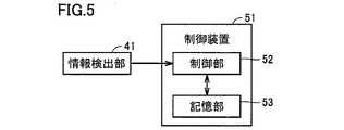
- FIG. 5 is a block diagram showing a configuration for recognizing information of a workpiece placed on a workpiece placement tool.
- machine tool 100 (work information recognition system) further includes control device 51.
- the control device 51 comprises a control panel (control panel) provided to the machine tool 100.
- the control device 51 receives the information of the reference block 31 from the information detection unit 41.
- the control device 51 includes a storage unit 53 and a control unit 52.
- the storage unit 53 stores data on the relationship between the information of the reference block 31 and the information of the work.
- the information on the workpiece may include information on the size, processing state, processing method or arrangement of the workpiece.
- the control unit 52 recognizes the information of the work placed on the work placement tool 20 by comparing the information of the reference block 31 detected by the information detection unit 41 with the data stored in the storage unit 53. .
- FIG. 6 is a table showing an example of data stored in the storage unit in FIG.
- FIG. 7 is a plan view showing an example of a workpiece placement tool on which workpieces of different types are placed.
- FIG. 8 is a plan view showing another example of a workpiece placement tool on which workpieces of different types are placed.
- the storage unit 53 has the size of the reference block 31 (longitudinal and lateral lengths of the square pillar-shaped reference block 31 in plan view) and the size of the workpiece W (cylindrical
- the correspondence relationship between the shape and the diameter and height of the workpiece W may be stored. More specifically, the storage unit 53 stores the vertical and horizontal lengths L1 of the reference block 31 in association with the diameter D1 and the height H1 of the workpiece W, and the vertical and horizontal lengths of the reference block 31
- the length L2 and the diameter D2 and height H2 of the work W are stored in association, and the vertical and horizontal lengths L3 of the reference block 31 and the diameter D3 and height H3 of the work W are stored in association May be
- all of the reference block 31A, the reference block 31B and the reference block 31C may have a size indicating the information of the work W.
- the reference block 31A has a size indicating the information of the work W, and the reference block 31B and the reference block 31C are used only to detect the inclination of the plate member 24 described later. It may be done.
- FIG. 9 is a table showing another example of data stored in the storage unit in FIG.
- FIG. 10 is a table showing still another example of data stored in the storage unit in FIG.
- the storage unit 53 may store the correspondence between the shape of the reference block 31 (the shape of the reference block 31 in a plan view thereof) and the processing state of the workpiece W and the processing method. More specifically, the storage unit 53 corresponds to the square shape of the reference block 31 and that the processing state of the workpiece W is unprocessed and the processing method of the workpiece W is processing using the processing program H And store the shape of the reference block 31 rectangular (longitudinal> horizontal), the machining state of the workpiece W is the first intermediate workpiece, and the machining method of the workpiece W is machining using the machining program I Are stored in association with each other, and the shape of the rectangle (longitudinal ⁇ horizontal) of the reference block 31 and the machining state of the workpiece W are the second intermediate workpiece, and the machining method of the workpiece W is machining using the machining program J And may be stored in association with each other.
- storage unit 53 places the position of reference block 31 (the coordinates of the center of reference block 31 in the plan view thereof) and the arrangement of workpiece W (a plurality of workpieces W are placed on workpiece placement tool 20).
- the correspondence between the mode being performed and the coordinates of the center of each work W in its plan view may be stored.
- the storage unit 53 is configured such that the central coordinates (X1, Y1, Z1) of the reference block 31, the plurality of works W are arranged in four lines in the Z axis direction, and five lines in the Y axis direction, A mode in which the central coordinates (X2, Y2, Z2) of the reference block 31 and the plurality of workpieces W are arranged in six rows in the Z-axis direction and six rows in the Y-axis direction.
- central coordinates of each work W may be stored in association with each other.
- the data stored in the storage unit 53 described above is an example, and the content of the information of the reference block 31, the content of the information of the work, the information of the reference block 31 to be associated with the information of the work
- the combination is not particularly limited.
- FIG. 11 is a flowchart showing steps of recognizing information of the work placed on the work placement tool.
- 12 to 14 are plan views showing a method of scanning a laser beam with respect to a reference block in the step of recognizing the information of the workpiece in FIG.
- a plurality of works W are placed on the work placement tool 20 (S101). In this step, the plurality of works W are inserted into the plurality of openings 28 respectively.
- the work placement tool 20 is set in the work storage area 151 (S102). In this step, the work placement tool 20 is placed on the drawer 156 in the open state. The work placement tool 20 is disposed in the work storage area 151 by closing the drawer 156.
- the information detection unit 41 detects information of the reference block 31 (31A, 31B, 31C) (S103).
- the information detection unit 41 is positioned above the reference block 31 by operating the work transfer unit 161 (moving mechanism unit 164, robot arm 165).
- the work transfer unit 161 By operating the work transfer unit 161 while emitting laser light downward from the information detection unit 41, the laser light is scanned along the Z-axis direction and the Y-axis direction.
- the information detection unit 41 receives the reflected light of the laser light.
- a difference occurs in the time when the laser light returns to the information detection unit 41 between the position where the reference block 31 is present and the position where the reference block 31 is not present.
- the scanning of the laser light is performed on each of the reference block 31A, the reference block 31B, and the reference block 31C.
- the central coordinates (Xa, Ya, Za) of the reference block 31A in plan view the central coordinates (Xb, Yb, Zb) of the reference block 31B in plan view, and the center of the reference block 31C in plan view
- the coordinates (Xc, Yc, Zc) are detected.
- the information detection unit 41 since the information detection unit 41 is provided in the work transfer unit 161 for transferring a work, the information detection unit 41 can be moved toward the reference block 31 without adding a new actuator. it can. Further, the accessibility of the information detection unit 41 to the reference block 31 can be improved.
- control unit 52 recognizes the information of the work W by comparing the information of the reference block 31 with the data stored in the storage unit 53 (S104).
- control unit 52 compares the information of the reference block 31 detected in the step of S103 with the data stored in the storage unit 53 to obtain the size of the work W (FIG. 6), and the work W
- the information on the processing state and the processing method (FIG. 9) and the arrangement of the workpiece W (FIG. 10) is recognized.
- the control unit 52 further detects the inclination of the plate member 24 in the workpiece mounting tool 20 from the center coordinates of the reference block 31A, the reference block 31B, and the reference block 31C.
- the control unit 52 corrects the position of each workpiece W placed on the workpiece placement tool 20 based on the detected inclination of the plate member 24.
- control unit 52 executes conveyance and processing of the work based on the obtained information of the work (S105).
- the control unit 52 grasps at which spatial position of the plurality of workpieces W exist in the workpiece storage area 151 based on the size of the workpiece W recognized in the previous step and the information on the disposition of the workpieces W doing. For this reason, the control unit 52 can operate the work transfer unit 161 such that the work gripping unit 172 of the robot arm 165 can be accurately positioned at a position and posture at which the work W can be gripped. Under the present circumstances, since the positional offset of the workpiece W resulting from the inclination of the plate member 24 is corrected in the previous step, the workpiece gripping portion 172 is applied to each workpiece W placed on the workpiece placement tool 20. Furthermore, positioning can be performed with high accuracy.
- the information detection unit 41 may emit a laser beam toward the work W and may receive the reflected light. By determining that the workpiece W is not present when the light receiving state of the reflected light is abnormal, it is possible to prevent the workpiece gripping portion 172 from holding the workpiece W in the vacant state.
- control unit 52 controls the processing of the workpiece W based on the processing state of the workpiece W recognized in the previous step and the information of the processing method. Perform the processing.
- the work information recognition system according to the present embodiment includes the work placement tool 20 on which the work can be placed, and the work placement.
- the control device 51 stores in the storage unit 53 the storage unit 53 for storing data on the relationship between the information in the reference block 31 and the information on the work, and the information in the reference block 31 detected by the information detection unit 41.
- a control unit 52 that recognizes information of the workpiece placed on the workpiece placement tool 20 by comparing the data.
- the reference block 31 is detachably provided on the work placement tool 20, the work placed on the work placement tool 20
- the reference block 31 provided in the reference block 31 may be replaced with the reference block 31 corresponding to the work. Therefore, it is possible to easily cope with the change of the type of work.
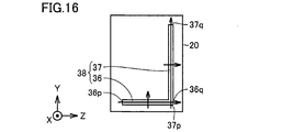
- FIG. 15 and 16 are plan views showing various modifications of the reference block shown in FIG. Referring to FIG. 15, in the present modification, a reference block 36 and a reference block 37 are provided in the work placement tool 20 instead of the reference block 31 in FIG. 12.
- the reference block 36 has an elongated shape extending along the Z-axis direction.
- the reference block 36 is provided along the edge of the workpiece placement tool 20 (plate member 24) extending in the Z-axis direction.
- the reference block 37 has an elongated shape extending along the Y-axis direction.
- the reference block 37 is provided along the edge of the work placement tool 20 (plate member 24) extending along the Z-axis direction.
- the laser light is emitted from the information detection unit 41 toward the reference block 36 at the step of S103 in FIG. It scans along each of the longitudinal direction (Z-axis direction) and the latitudinal direction (Y-axis direction). Thereby, the coordinates of one end 36 p and the other end 36 q in the longitudinal direction of the reference block 36 are detected. Further, the laser light is emitted from the information detection unit 41 toward the reference block 37, and the work conveyance unit 161 is operated to allow the laser light to be in the longitudinal direction (Y-axis direction) and the short direction (Z Scan along each axis). Thereby, the coordinates of one end 37p and the other end 37q in the longitudinal direction of the reference block 37 are detected.
- control unit 52 sets the workpiece placement tool 20 from the coordinates of one end 36p and the other end 36q of the reference block 36 and the coordinates of the one end 37p and the other end 37q of the reference block 37.
- a workpiece mounting tool 20 is provided with a reference block 38 in place of the reference block 31 in FIG.
- the reference block 38 has a shape in which the reference block 36 and the reference block 37 in FIG. 15 are connected at the corner of the work placement tool 20 (plate member 24).
- the laser beam is scanned along the Y-axis direction and the Z-axis direction in the portion of the reference block 36 and the portion of the reference block 37 to tilt the plate member 24 in the workpiece mounting tool 20.
- three reference blocks are not necessarily required, and two reference blocks 36 and 37 may be used, or one reference block 38 may be used. Also, the inclination of the plate material 24 may be detected using four or more reference blocks.
- the reference block may be provided on the tray 21 of the work placement tool 20.
- the reference object in the present invention is not limited to the above-described three-dimensional reference block, and may be, for example, a sheet-like mirror.
- the reference object is a solid reference block, the durability of the reference object can be improved.
- the reference object is a sheet-like mirror, the degree of freedom of the installation location of the reference object can be increased.
- the workpiece information recognition system in the present invention is not limited to a machine tool, and may be applied to various workpiece processing devices such as a workpiece measuring device and a workpiece cleaning device.
- a work information recognition system comprises a work placement tool on which a work can be placed, a reference object detachably provided on the work placement tool, an information detection unit for detecting information of the reference object, and information And a controller configured to receive information on a reference object from the detection unit.
- the control device compares the data stored in the storage unit with the storage unit that stores data on the relationship between the information on the reference object and the information on the work, and the information on the reference object detected by the information detection unit. And a control unit that recognizes information of the workpiece placed on the workpiece placement tool.
- the reference object provided on the workpiece placement tool may be replaced with the reference object corresponding to the workpiece. Therefore, it is possible to easily cope with the change of the type of work.
- the information on the reference object includes information on the size, shape or position of the reference object.
- the information of the work placed on the work placement tool can be recognized through various information on the reference object.
- the information on the workpiece includes information on the size, processing state, processing method or arrangement of the workpiece.
- various information on the work placed on the work placement tool can be recognized through the information of the reference object.
- the work placement tool includes a plate material provided with a plurality of openings into which the work is inserted.
- the plate is provided with at least three reference objects which are arranged apart from one another.
- the inclination of the plate material can be recognized through the positions of the three reference objects.
- the reference object is a solid. According to the work information recognition system configured as described above, the durability of the reference object can be improved.
- the work information recognition system further includes a work transfer unit for transferring the work placed on the work placement tool.
- the information detection unit is fixed to the work transfer unit.
- the information detection unit can be moved toward the reference object by using the work transfer unit for transferring the work.
- the present invention is applied to, for example, a machine tool.
Landscapes
- Engineering & Computer Science (AREA)
- Mechanical Engineering (AREA)
- Robotics (AREA)
- Physics & Mathematics (AREA)
- Optics & Photonics (AREA)
- Automation & Control Theory (AREA)
- Manipulator (AREA)
- Feeding Of Workpieces (AREA)
- Turning (AREA)
- Machine Tool Sensing Apparatuses (AREA)
- Numerical Control (AREA)
Abstract
ワーク情報認識システムは、ワークを載置可能なワーク載置具(20)と、ワーク載置具(20)に着脱可能に設けられる基準ブロック(31)と、基準ブロック(31)の情報を検出する情報検出部と、情報検出部から基準ブロック(31)の情報を受ける制御装置とを備える。制御装置は、基準ブロック(31)の情報と、ワークの情報との関係に関するデータを記憶する記憶部と、情報検出部により検出された基準ブロック(31)の情報を、記憶部に記憶されたデータに照らし合わせることにより、ワーク載置具(20)に載置されるワークの情報を認識する制御部とを有する。このような構成により、ワークの種類の変更に容易に対応することが可能なワーク情報認識システムを提供する。
Description
この発明は、ワーク情報認識システムに関する。
従来のワーク情報認識システムに関連して、たとえば、実開平2-52399号公報には、プリント配線基板などの各種基板に関するデータの管理に用いられる基板管理装置が開示されている(特許文献1)。
特許文献1に開示される基板管理装置は、基板を収容するとともに、識別表示を付して個別化されたトレーと、識別表示からトレーを判別する認識手段と、認識表示により得られるトレーの認識データとともに、トレーに収容される基板のデータを記憶し、記憶したトレーの識別データから収容されている基板のデータを任意に取り出し可能にしたデータ処理手段とを備える。トレーに付される識別表示として、トレーに識別孔が設けられたり、バーコードが印刷されたりする。
上述の特許文献1に開示されるように、基板に関する情報を認識するために、基板を収容するトレーに識別孔やバーコードといった識別表示を設ける手法が知られており、このような手法を、ワーク載置具に載置されるワークの情報認識システムに適用することが考えられる。しかしながら、この場合、ワークの種類が変更となる毎に、そのワークに対応する識別表示を備えたワーク載置具を準備する必要が生じる。これにより、ワーク載置具の数が増えたり、事前の準備作業が煩雑になったりして、ワークの種類の変更に容易に対応することができない。
そこでこの発明の目的は、上記の課題を解決することであり、ワークの種類の変更に容易に対応することが可能なワーク情報認識システムを提供することである。
この発明に従ったワーク情報認識システムは、ワークを載置可能なワーク載置具と、ワーク載置具に着脱可能に設けられる基準物体と、基準物体の情報を検出する情報検出部と、情報検出部から基準物体の情報を受ける制御装置とを備える。制御装置は、基準物体の情報と、ワークの情報との関係に関するデータを記憶する記憶部と、情報検出部により検出された基準物体の情報を、記憶部に記憶されたデータに照らし合わせることにより、ワーク載置具に載置されるワークの情報を認識する制御部とを有する。
この発明に従えば、ワークの種類の変更に容易に対応することが可能なワーク情報認識システムを提供することができる。
この発明の実施の形態について、図面を参照して説明する。なお、以下で参照する図面では、同一またはそれに相当する部材には、同じ番号が付されている。
図1は、この発明の実施の形態におけるワーク情報認識システムが適用された工作機械を示す平面図である。
図1を参照して、本実施の形態におけるワーク情報認識システムは、ワークの情報を認識するためのシステムである。本実施の形態では、一例として、ワーク情報認識システムが、ワークを加工する工作機械100に適用されている。工作機械100は、固定工具を用いた旋削機能と、回転工具を用いたミーリング機能とを有する複合加工機である。
まず、工作機械100の基本的な構成について説明する。工作機械100(ワーク情報認識システム)は、第1主軸121と、第2主軸122と、工具主軸123と、スプラッシュガード115とを有する。第1主軸121、第2主軸122および工具主軸123は、加工エリア141内に設けられている。
第1主軸121および第2主軸122は、水平方向に延びるZ軸方向において、互いに対向して配置されている。第1主軸121は、Z軸に平行な中心軸131を中心に回転可能に設けられ、第2主軸122は、Z軸に平行な中心軸132を中心に回転可能に設けられている。第1主軸121および第2主軸122には、ワークを着脱可能に保持するためのチャック機構が設けられている。第2主軸122は、Z軸方向に移動可能に設けられている。
工具主軸123は、ワークの旋削加工時に固定工具を保持したり、ワークのミーリング加工時に、回転工具を保持して、中心軸133を中心に回転させたりする。工具主軸123には、工具を着脱可能に保持するためのクランプ機構が設けられている。工具主軸123は、鉛直方向に延びるX軸方向、水平方向に延び、Z軸方向に直交するY軸方向、および、Z軸方向に移動可能に設けられている。工具主軸123は、さらに、Y軸に平行な中心軸134を中心に旋回可能に設けられている。
スプラッシュガード115は、後述するカバー体152とともに工作機械100の外観をなしている。スプラッシュガード115は、加工エリア141を区画形成している。
工作機械100(ワーク情報認識システム)は、ワーク搬送部161と、カバー体152と、ワーク載置具20とをさらに有する。ワーク搬送部161は、加工エリア141およびワーク収納エリア151の間でワークを搬送する。
カバー体152は、ワーク収納エリア151を区画形成している。ワーク収納エリア151は、加工エリア141と隣り合って設けられている。ワーク収納エリア151は、Z軸方向において加工エリア141と隣り合って設けられている。加工エリア141およびワーク収納エリア151の間は、開閉可能なシャッター(不図示)により隔てられている。
ワーク搬送部161は、移動機構部164と、ロボットアーム165とを有する。ロボットアーム165は、移動機構部164からアーム状に延出している。ロボットアーム165は、ワークを把持可能なように構成されている。ロボットアーム165は、把持したワークを空間内で自在に移動させるとともに、把持したワークの姿勢を自在に変化させることが可能なように構成されている。ロボットアーム165は、6軸を互いに独立して制御可能なロボットアームである。
移動機構部164は、ロボットアーム165を、加工エリア141およびワーク収納エリア151の間で移動させる。移動機構部164は、ロボットアーム165を、Z軸方向に沿って直線往復移動させる。移動機構部164は、ロボットアーム165をZ軸に平行な方向に案内するリニアガイド、回転運動を出力するサーボモータ、および、サーボモータから出力された回転運動を直線運動に変換して、ロボットアーム165をZ軸方向に移動させるラックピニオン等から構成されている。
なお、本発明におけるワーク搬送部は、ワークを搬送可能な構成であれば特に限定されず、たとえば、X軸、Y軸およびZ軸の3軸に移動可能な3軸ローダであってもよい。
図2は、図1中のワーク収納エリアに配置されるワーク載置具を示す斜視図である。図3は、図2中のワーク載置具からトレイを除いた状態を示す斜視図である。
図1から図3を参照して、工作機械100(ワーク情報認識システム)は、ワーク載置具20と、引き出し156とをさらに有する。
引き出し156は、カバー体152の機械前面に設けられている。引き出し156は、図1中の矢印157に示すように、Y軸方向に沿ってスライド可能に設けられている。引き出し156は、ワーク収納エリア151に向けて押し込まれる閉状態と、ワーク収納エリア151から機械前方に引き出される開状態との間において、スライド可能に設けられている。
ワーク載置具20は、ワークWが載置可能なように構成されている。ワーク載置具20は、複数のワークWが載置可能なように構成されている。ワーク載置具20は、ワーク収納エリア151に配置されている。ワーク載置具20は、引き出し156に載置されている。引き出し156に載置されたワーク載置具20は、引き出し156が閉状態とされることによって、ワーク収納エリア151に配置される。引き出し156に載置されたワーク載置具20は、引き出し156が開状態とされることによって、ワーク収納エリア151の外部に配置される。
本実施の形態では、2組のワーク載置具20および引き出し156が、Z軸方向に並んで設けられている。代表的な例として、一方のワーク載置具20には、加工前のワークWが載置され、他方のワーク載置具20には、加工後のワークWが載置される。図2および図3中には、円柱形状を有する加工前のワークWが示されている。
ワーク載置具20は、トレイ21と、プレート材(中敷き)24とを有する。トレイ21は、浅底の箱形状を有する。プレート材24は、トレイ21に収容されている。プレート材24は、全体として、平面状に広がる板形状を有する。ワーク載置具20がワーク収納エリア151に配置された状態において、プレート材24は、Y軸-Z軸平面に平行に設けられている。プレート材24は、X軸方向から見た場合に矩形形状の平面視を有する。
プレート材24は、ベースプレート25と、スペーサ26と、トッププレート27とを有する。ベースプレート25は、トッププレート27よりも大きい平面形状を有する。ベースプレート25およびトッププレート27は、プレート材24の厚み方向において互いに重ね合わされている。トッププレート27には、複数の開口部28が設けられている。開口部28は、プレート材24の厚み方向において、トッププレート27を貫通している。開口部28は、ワークWの形状に対応する開口面(本実施の形態では、円形の開口面)を有する。ワーク載置具20がワーク収納エリア151に配置された状態において、複数の開口部28は、Y軸方向およびZ軸方向に沿って格子状に並んで設けられている。
スペーサ26は、トッププレート27の周縁に沿って帯状に延びる枠形状を有する。スペーサ26は、プレート材24の厚み方向において、ベースプレート25およびトッププレート27の間に介挿されている。これにより、開口部28の直下では、ベースプレート25およびトッププレート27の間に隙間が設けられている。ワークWが開口部28に挿入され、ベースプレート25上に載置されることによって、ワークWは、プレート材24により保持される。
続いて、ワーク収納エリア151において、ワーク載置具20に載置されたワークWの各種情報を認識するための構成について説明する。
工作機械100(ワーク情報認識システム)は、基準物体としての基準ブロック31をさらに有する。
基準ブロック31は、ワーク載置具20に着脱可能に設けられている。ワーク載置具20には、複数の基準ブロック31が設けられている。ワーク載置具20には、少なくとも3つの基準ブロック31が設けられている。ワーク載置具20には、基準ブロック31A、基準ブロック31Bおよび基準ブロック31Cが設けられている。
基準ブロック31は、ワーク載置具20のうちのプレート材24に設けられている。基準ブロック31は、プレート材24のうちのベースプレート25に設けられている。基準ブロック31は、ボルトによりワーク載置具20に締結されている。基準ブロック31は、そのボルトを外すことによって、ワーク載置具20から取り外し可能である。
複数の基準ブロック31(31A,31B,31C)は、互いに離れて配置されている。複数の基準ブロック31は、プレート材24が広がる平面内において互いに離れて配置されている。複数の基準ブロック31は、トッププレート27から露出するベースプレート25の周縁部に設けられている。複数の基準ブロック31は、複数の開口部28が設けられる領域(すなわち、複数のワークWが保持される領域)の外側の領域に設けられている。
基準ブロック31Aと、基準ブロック31Bおよび基準ブロック31Cとは、プレート材24が有する矩形形状の平面視の長手方向に離れて設けられている。基準ブロック31Bと、基準ブロック31Cとは、プレート材24が有する矩形形状の平面視の短手方向に離れて設けられている。基準ブロック31Aは、プレート材24が有する矩形形状の平面視の短手方向において、基準ブロック31Bおよび基準ブロック31Cの間の中心位置に設けられている。基準ブロック31A、基準ブロック31Bおよび基準ブロック31Cは、二等辺三角形が有する3つの角部にそれぞれ位置している。
なお、基準ブロック31がワーク載置具20に着脱可能に設けられる方法は、上記のボルトを用いた方法に限られず、たとえば、クリップまたは嵌め込みを用いた方法であってもよい。また、基準ブロック31A、基準ブロック31Bおよび基準ブロック31Cが設けられる位置は、特に限定されない。しかしながら、上記に説明した構成によれば、基準ブロック31A、基準ブロック31Bおよび基準ブロック31Cを、プレート材24が広がる平面内において互いに大きく離して配置することが可能である。
基準ブロック31は、立体である。基準ブロック31は、ベースプレート25から突出する凸形状を有する。本実施の形態では、基準ブロック31は、四角柱のブロックから構成されている。ワーク載置具20がワーク収納エリア151に配置された状態において、基準ブロック31は、Y軸方向に延びる縦と、Z軸方向に延びる横とが、互いに等しい長さとなり、X軸方向に延びる高さが、縦および横の各々よりも大きい長さとなる四角柱形状を有する。
なお、基準ブロック31は、上記の四角柱に限られず、たとえば、縦および横の長さが異なる四角柱形状を有してもよい。基準ブロック31は、X軸方向に延びる高さが、縦および横の各々と等しい四角柱形状、または、X軸方向に延びる高さが、縦および横の各々よりも小さい長さとなる四角柱形状を有してもよい。また、基準ブロック31は、円柱形状を有してもよいし、三角柱形状を有してもよい。
図4は、図1中のロボットアームの先端部を示す斜視図である。図1および図4を参照して、ロボットアーム165は、可動部171と、ワーク把持部172(172P,172Q)とを有する。
可動部171は、移動機構部164からアーム状に延出するロボットアーム165の先端に設けられている。可動部171は、図4中に示す回動軸181を中心に揺動可能に設けられるとともに、図4中に示す回転軸182を中心に回転可能に設けられている。
可動部171には、ワーク把持部172が設けられている。ワーク把持部172は、ワークを着脱可能に把持するように構成されている。本実施の形態では、同時に2つのワークを把持するために、ワーク把持部172として、ワーク把持部172Pおよびワーク把持部172Qが設けられている。
工作機械100(ワーク情報認識システム)は、情報検出部41をさらに有する。情報検出部41は、基準ブロック31の情報を検出するように構成されている。基準ブロック31の情報は、基準ブロック31の大きさ、形状または位置に関する情報を含んでもよい。
情報検出部41は、レーザセンサからなる。情報検出部41は、レーザ光を出射する出射部(不図示)と、出射部から出射され、対象物に反射されたレーザ光を受ける受光部(不図示)とを有する。情報検出部41は、受光部におけるレーザ光の受光位置や、レーザ光が出射部から受光部に戻るまでの時間に基づいて、対象物の位置情報を検出することが可能である。
情報検出部41は、ワーク搬送部161に固定されている。情報検出部41は、ロボットアーム165に固定されている。情報検出部41は、ロボットアーム165のうちの可動部171に固定されている。情報検出部41は、ワーク把持部172と隣り合って設けられている。このような構成により、ワーク搬送部161の動作に伴って、情報検出部41を空間内で自在に移動させるとともに、情報検出部41の姿勢を自在に変化させることができる。
なお、本発明における情報検出部は、基準物体の各種情報を検出可能なものであれば特に限定されず、たとえば、接触式スライラスであってもよい。また、本実施の形態では、情報検出部41がワーク搬送部161に固定される場合を説明したが、これに限られず、たとえば、情報検出部41を移動させるための専用のアクチュエータが設けられてもよい。
図5は、ワーク載置具に載置されたワークの情報を認識するための構成を示すブロック図である。
図1および図5を参照して、工作機械100(ワーク情報認識システム)は、制御装置51をさらに有する。制御装置51は、工作機械100に備え付けられる制御盤(コントロールパネル)からなる。制御装置51は、情報検出部41から基準ブロック31の情報を受ける。制御装置51は、記憶部53と、制御部52とを有する。
記憶部53は、基準ブロック31の情報と、ワークの情報との関係に関するデータを記憶する。ワークの情報は、ワークの大きさ、加工状態、加工方法または配置に関する情報を含んでもよい。
制御部52は、情報検出部41により検出された基準ブロック31の情報を、記憶部53に記憶されたデータに照らし合わせることにより、ワーク載置具20に載置されるワークの情報を認識する。
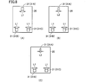
図6は、図5中の記憶部に記憶されるデータの例を示す表である。図7は、互いに異なる種類のワークが載置されるワーク載置具の例を示す平面図である。図8は、互いに異なる種類のワークが載置されるワーク載置具の別の例を示す平面図である。
図6から図8を参照して、記憶部53は、基準ブロック31の大きさ(四角柱形状の基準ブロック31のその平面視における縦および横の長さ)と、ワークWの大きさ(円柱形状のワークWの直径および高さ)との対応関係を記憶してもよい。より具体的には、記憶部53は、基準ブロック31の縦および横の長さL1と、ワークWの直径D1および高さH1とを対応付けて記憶し、基準ブロック31の縦および横の長さL2と、ワークWの直径D2および高さH2とを対応付けて記憶し、基準ブロック31の縦および横の長さL3と、ワークWの直径D3および高さH3とを対応付けて記憶してもよい。
この際、図7中に示すように、基準ブロック31A、基準ブロック31Bおよび基準ブロック31Cの全てが、ワークWの情報を示す大きさを有してもよい。また、図8中に示すように、基準ブロック31Aが、ワークWの情報を示す大きさを有し、基準ブロック31Bおよび基準ブロック31Cは、後述するプレート材24の傾きを検出するためにのみ用いられてもよい。
図9は、図5中の記憶部に記憶されるデータの別の例を示す表である。図10は、図5中の記憶部に記憶されるデータのさらに別の例を示す表である。
図9を参照して、記憶部53は、基準ブロック31の形状(基準ブロック31のその平面視における形状)と、ワークWの加工状態および加工方法との対応関係を記憶してもよい。より具体的には、記憶部53は、基準ブロック31の正方形の形状と、ワークWの加工状態が未加工であり、ワークWの加工方法が加工プラグラムHを用いた加工であることとを対応付けて記憶し、基準ブロック31の長方形(縦>横)の形状と、ワークWの加工状態が第1中間加工物であり、ワークWの加工方法が加工プログラムIを用いた加工であることとを対応付けて記憶し、基準ブロック31の長方形(縦<横)の形状と、ワークWの加工状態が第2中間加工物であり、ワークWの加工方法が加工プログラムJを用いた加工であることとを対応付けて記憶してもよい。
図10を参照して、記憶部53は、基準ブロック31の位置(基準ブロック31のその平面視における中心の座標)と、ワークWの配置(複数のワークWがワーク載置具20に載置される態様と、各ワークWのその平面視における中心の座標)との対応関係を記憶してもよい。より具体的には、記憶部53は、基準ブロック31の中心座標(X1,Y1,Z1)と、複数のワークWがZ軸方向に4列、Y軸方向に5行並ぶ態様、および、各ワークWの中心座標とを対応付けて記憶し、基準ブロック31の中心座標(X2,Y2,Z2)と、複数のワークWがZ軸方向に6列、Y軸方向に6行並ぶ態様、および、各ワークWの中心座標とを対応付けて記憶し、基準ブロック31の中心座標(X3,Y3,Z3)と、複数のワークWがZ軸方向に7列、Y軸方向に8行並ぶ態様、および、各ワークWの中心座標とを対応付けて記憶してもよい。
なお、以上に説明した記憶部53に記憶されるデータは、一例であって、基準ブロック31の情報の内容や、ワークの情報の内容、対応付けられる基準ブロック31の情報とワークの情報との組み合わせは、特に限定されない。
図11は、ワーク載置具に載置されたワークの情報を認識するステップを示すフローチャートである。図12から図14は、図11中のワークの情報を認識するステップにおいて、基準ブロックに対するレーザ光の走査方法を示す平面図である。
以下、ワーク載置具20に設けられた基準ブロック31(31A,31B,31C)のの情報に基づいて、ワーク載置具20に載置されたワークWの情報を認識するステップについて説明する。
図1から図3および図11を参照して、まず、複数のワークWをワーク載置具20に載置する(S101)。本ステップでは、複数のワークWを複数の開口部28にそれぞれ挿入する。
次に、ワーク載置具20を、ワーク収納エリア151にセッティングする(S102)。本ステップでは、開状態とした引き出し156にワーク載置具20を載置する。引き出し156を閉状態とすることにより、ワーク載置具20をワーク収納エリア151に配置する。
図7から図14を参照して、次に、情報検出部41により、基準ブロック31(31A,31B,31C)の情報を検出する(S103)。
本ステップでは、ワーク搬送部161(移動機構部164,ロボットアーム165)を動作させることによって、情報検出部41を基準ブロック31の上方に位置決めする。情報検出部41から下方に向けてレーザ光を出射しながら、ワーク搬送部161を動作させることにより、レーザ光をZ軸方向およびY軸方向の各々に沿って走査する。レーザ光の走査とともに、情報検出部41にてレーザ光の反射光を受ける。このとき、基準ブロック31が存在する位置と存在しない位置との間では、情報検出部41にレーザ光が戻る時間に差が生じる。レーザ光の戻り時間に差が生じたタイミングにおけるワーク搬送部161の動作位置に基づいて、基準ブロック31の大きさ(基準ブロック31のその平面視における縦および横の長さ)と、基準ブロック31の形状(基準ブロック31のその平面視における形状)とを検出する。また、レーザ光の戻り時間と、ワーク搬送部161の動作位置とを合わせて考慮することにより、基準ブロック31の位置(基準ブロック31のその平面視における中心の座標)を検出する。
上記レーザ光の走査を、基準ブロック31A、基準ブロック31Bおよび基準ブロック31Cの各々に対して実行する。これにより、基準ブロック31Aのその平面視における中心座標(Xa,Ya,Za)と、基準ブロック31Bのその平面視における中心座標(Xb,Yb,Zb)と、基準ブロック31Cのその平面視における中心座標(Xc,Yc,Zc)とを検出する。
本実施の形態では、情報検出部41が、ワーク搬送のためのワーク搬送部161に設けられるため、新たなアクチュエータを追加することなく、情報検出部41を基準ブロック31に向けて移動させることができる。また、基準ブロック31に対する情報検出部41の接近性を良好にできる。
次に、制御部52は、基準ブロック31の情報を、記憶部53に記憶されるデータに照らし合わせることによって、ワークWの情報を認識する(S104)。
本ステップでは、制御部52が、S103のステップで検出された基準ブロック31の情報を、記憶部53に記憶されるデータに照らし合わせることによって、ワークWの大きさ(図6)と、ワークWの加工状態および加工方法(図9)と、ワークWの配置(図10)とに関する情報を認識する。
制御部52は、さらに、基準ブロック31A、基準ブロック31Bおよび基準ブロック31Cの中心座標から、ワーク載置具20におけるプレート材24の傾きを検出する。制御部52は、検出されたプレート材24の傾きに基づいて、ワーク載置具20に載置された各ワークWの位置を補正する。
次に、制御部52は、得られたワークの情報に基づいて、ワークの搬送および加工を実行する(S105)。
制御部52は、先のステップで認識したワークWの大きさと、ワークWの配置とに関する情報により、複数のワークWがワーク収納エリア151のいずれの空間位置にどのように存在しているかを把握している。このため、制御部52は、ロボットアーム165のワーク把持部172がワークWを把持可能な位置および姿勢に正確に位置決めされるように、ワーク搬送部161を動作させることができる。この際、先のステップにて、プレート材24の傾きに起因したワークWの位置ずれが補正されているため、ワーク載置具20に載置された各ワークWに対してワーク把持部172をさらに精度よく位置決めすることができる。
なお、ロボットアーム165によりワークWを把持する際に、情報検出部41にてレーザ光をワークWに向けて出射し、その反射光を受光するステップを実行してもよい。反射光の受光状態が異常である場合にワークWが存在しないと判断することにより、ワーク把持部172によるワークWの空掴みを防ぐことができる。
ワーク搬送部161によりワークWをワーク収納エリア151から加工エリア141に移動させたあと、制御部52は、先のステップで認識したワークWの加工状態および加工方法の情報に基づいて、ワークWの加工を実行する。
以上に説明した、この発明の実施の形態におけるワーク情報認識システムの構成についてまとめて説明すると、本実施の形態におけるワーク情報認識システムは、ワークを載置可能なワーク載置具20と、ワーク載置具20に着脱可能に設けられる基準物体としての基準ブロック31と、基準ブロック31の情報を検出する情報検出部41と、情報検出部41から基準ブロック31の情報を受ける制御装置51とを備える。制御装置51は、基準ブロック31の情報と、ワークの情報との関係に関するデータを記憶する記憶部53と、情報検出部41により検出された基準ブロック31の情報を、記憶部53に記憶されたデータに照らし合わせることにより、ワーク載置具20に載置されるワークの情報を認識する制御部52とを有する。
このように構成された、この発明の実施の形態におけるワーク情報認識システムによれば、基準ブロック31がワーク載置具20に着脱可能に設けられるため、ワーク載置具20に載置されるワークの種類が変更になった場合には、基準ブロック31に設けられる基準ブロック31を、そのワークに対応する基準ブロック31に取り換えればよい。このため、ワークの種類の変更に容易に対応することができる。
図15および図16は、図12中に示す基準ブロックの各種変形例を示す平面図である。図15を参照して、本変形例では、ワーク載置具20に、図12中の基準ブロック31に替えて、基準ブロック36および基準ブロック37が設けられている。
基準ブロック36は、Z軸方向に沿って延びる長尺形状を有する。基準ブロック36は、Z軸方向に延びるワーク載置具20(プレート材24)の端辺に沿って設けられている。基準ブロック37は、Y軸方向に沿って延びる長尺形状を有する。基準ブロック37は、Z軸方向に沿って延びるワーク載置具20(プレート材24)の端辺に沿って設けられている。
このような構成において、図11中のS103のステップ時、情報検出部41から基準ブロック36に向けてレーザ光を出射しながら、ワーク搬送部161を動作させることにより、レーザ光を基準ブロック36の長手方向(Z軸方向)および短手方向(Y軸方向)の各々に沿って走査する。これにより、基準ブロック36の長手方向における一方端36pおよび他方端36qの座標を検出する。また、情報検出部41から基準ブロック37に向けてレーザ光を出射しながら、ワーク搬送部161を動作させることにより、レーザ光を基準ブロック37の長手方向(Y軸方向)および短手方向(Z軸方向)の各々に沿って走査する。これにより、基準ブロック37の長手方向における一方端37pおよび他方端37qの座標を検出する。
図11中のS104のステップ時、制御部52は、基準ブロック36の一方端36pおよび他方端36qの座標と、基準ブロック37の一方端37pおよび他方端37qの座標とから、ワーク載置具20におけるプレート材24の傾きを検出する。
図16を参照して、本変形例では、ワーク載置具20に、図12中の基準ブロック31に替えて、基準ブロック38が設けられている。基準ブロック38は、図15中の基準ブロック36と基準ブロック37とが、ワーク載置具20(プレート材24)の角部で繋がった形状を有する。
本変形例においても、レーザ光を、基準ブロック36の部分と基準ブロック37の部分とに、Y軸方向およびZ軸方向に沿って走査することにより、ワーク載置具20におけるプレート材24の傾きを検出する。
このように、プレート材24の傾きを検出するに際しては、必ずしも3つの基準ブロックが必要ではなく、2つの基準ブロック36,37を用いてもよいし、1つの基準ブロック38を用いてもよい。また、4つ以上の基準ブロックを用いて、プレート材24の傾きを検出してもよい。
なお、本実施の形態では、基準ブロックをワーク載置具20のうちのプレート材24に設ける場合を説明したが、基準ブロックをワーク載置具20のうちのトレイ21に設けてもよい。
また、本発明における基準物体は、上記の立体である基準ブロックに限定されず、たとえば、シート状のミラーであってよい。基準物体を立体である基準ブロックとした場合、基準物体の耐久性を向上させることができる。基準物体をシート状のミラーとした場合、基準物体の設置場所の自由度を上げることができる。
本発明におけるワーク情報認識システムは、工作機械に限られず、たとえば、ワーク測定装置やワーク洗浄装置などの各種のワーク処理装置に適用されてもよい。
以下、本発明をまとめて説明する。この発明に従ったワーク情報認識システムは、ワークを載置可能なワーク載置具と、ワーク載置具に着脱可能に設けられる基準物体と、基準物体の情報を検出する情報検出部と、情報検出部から基準物体の情報を受ける制御装置とを備える。制御装置は、基準物体の情報と、ワークの情報との関係に関するデータを記憶する記憶部と、情報検出部により検出された基準物体の情報を、記憶部に記憶されたデータに照らし合わせることにより、ワーク載置具に載置されるワークの情報を認識する制御部とを有する。
このように構成されたワーク情報認識システムによれば、ワークの種類が変更になった場合に、ワーク載置具に設けられる基準物体を、そのワークに対応する基準物体に取り換えればよい。このため、ワークの種類の変更に容易に対応することができる。
また好ましくは、基準物体の情報は、基準物体の大きさ、形状または位置に関する情報を含む。
このように構成されたワーク情報認識システムによれば、基準物体に関する種々の情報を通じて、ワーク載置具に載置されるワークの情報を認識することができる。
また好ましくは、ワークの情報は、ワークの大きさ、加工状態、加工方法または配置に関する情報を含む。
このように構成されたワーク情報認識システムによれば、基準物体の情報を通じて、ワーク載置具に載置されるワークに関する種々の情報を認識することができる。
また好ましくは、ワーク載置具は、ワークが挿入される複数の開口部が設けられるプレート材を含む。プレート材には、互いに離れて配置される少なくとも3つの基準物体が設けられる。
このように構成されたワーク情報認識システムによれば、3つの基準物体の位置を通じて、プレート材の傾きを認識することができる。
また好ましくは、基準物体は、立体である。
このように構成されたワーク情報認識システムによれば、基準物体の耐久性を向上させることができる。
このように構成されたワーク情報認識システムによれば、基準物体の耐久性を向上させることができる。
また好ましくは、ワーク情報認識システムは、ワーク載置具に載置されるワークを搬送するワーク搬送部をさらに備える。情報検出部は、ワーク搬送部に固定される。
このように構成されたワーク情報認識システムによれば、ワークを搬送するためのワーク搬送部を利用して、情報検出部を基準物体に向けて移動させることができる。
今回開示された実施の形態はすべての点で例示であって制限的なものではないと考えられるべきである。本発明の範囲は上記した説明ではなくて請求の範囲によって示され、請求の範囲と均等の意味および範囲内でのすべての変更が含まれることが意図される。
本発明は、たとえば、工作機械に適用される。
20 載置具、21 トレイ、24 プレート材、25 ベースプレート、26 スペーサ、27 トッププレート、28 開口部、31,31A,31B,31C,36,37,38 基準ブロック、36p,37p 一方端、36q,37q 他方端、41 情報検出部、51 制御装置、52 制御部、53 記憶部、100 工作機械、115 スプラッシュガード、121 第1主軸、122 第2主軸、123 工具主軸、131,132,133,134 中心軸、141 加工エリア、151 ワーク収納エリア、152 カバー体、156 引き出し、161 ワーク搬送部、164 移動機構部、165 ロボットアーム、171 可動部、172,172P,172Q ワーク把持部、181 回動軸、182 回転軸。
Claims (6)
- ワークを載置可能なワーク載置具と、
前記ワーク載置具に着脱可能に設けられる基準物体と、
前記基準物体の情報を検出する情報検出部と、
前記情報検出部から前記基準物体の情報を受ける制御装置とを備え、
前記制御装置は、
前記基準物体の情報と、ワークの情報との関係に関するデータを記憶する記憶部と、
前記情報検出部により検出された前記基準物体の情報を、前記記憶部に記憶されたデータに照らし合わせることにより、前記ワーク載置具に載置されるワークの情報を認識する制御部とを有する、ワーク情報認識システム。 - 前記基準物体の情報は、前記基準物体の大きさ、形状または位置に関する情報を含む、請求項1に記載のワーク情報認識システム。
- 前記ワークの情報は、前記ワークの大きさ、加工状態、加工方法または配置に関する情報を含む、請求項1または2に記載のワーク情報認識システム。
- 前記ワーク載置具は、ワークが挿入される複数の開口部が設けられるプレート材を含み、
前記プレート材には、互いに離れて配置される少なくとも3つの前記基準物体が設けられる、請求項1から3のいずれか1項に記載のワーク情報認識システム。 - 前記基準物体は、立体である、請求項1から4のいずれか1項に記載のワーク情報認識システム。
- 前記ワーク載置具に載置されるワークを搬送するワーク搬送部をさらに備え、
前記情報検出部は、前記ワーク搬送部に固定される、請求項1から5のいずれか1項に記載のワーク情報認識システム。
Priority Applications (3)
| Application Number | Priority Date | Filing Date | Title |
|---|---|---|---|
| US16/640,618 US11247304B2 (en) | 2017-08-22 | 2018-08-20 | Workpiece information recognition system |
| CN201880054611.0A CN111050999B (zh) | 2017-08-22 | 2018-08-20 | 工件信息识别系统 |
| EP18847825.9A EP3674032B1 (en) | 2017-08-22 | 2018-08-20 | Workpiece information recognition system |
Applications Claiming Priority (2)
| Application Number | Priority Date | Filing Date | Title |
|---|---|---|---|
| JP2017-159253 | 2017-08-22 | ||
| JP2017159253A JP6748616B2 (ja) | 2017-08-22 | 2017-08-22 | ワーク情報認識システム |
Publications (1)
| Publication Number | Publication Date |
|---|---|
| WO2019039431A1 true WO2019039431A1 (ja) | 2019-02-28 |
Family
ID=65438909
Family Applications (1)
| Application Number | Title | Priority Date | Filing Date |
|---|---|---|---|
| PCT/JP2018/030649 Ceased WO2019039431A1 (ja) | 2017-08-22 | 2018-08-20 | ワーク情報認識システム |
Country Status (5)
| Country | Link |
|---|---|
| US (1) | US11247304B2 (ja) |
| EP (1) | EP3674032B1 (ja) |
| JP (1) | JP6748616B2 (ja) |
| CN (1) | CN111050999B (ja) |
| WO (1) | WO2019039431A1 (ja) |
Cited By (1)
| Publication number | Priority date | Publication date | Assignee | Title |
|---|---|---|---|---|
| JP7654149B1 (ja) * | 2024-10-11 | 2025-03-31 | Dmg森精機株式会社 | 工作機械、制御方法、および制御プログラム |
Families Citing this family (7)
| Publication number | Priority date | Publication date | Assignee | Title |
|---|---|---|---|---|
| JP7223571B2 (ja) * | 2018-12-13 | 2023-02-16 | 川崎重工業株式会社 | ロボット及びそれを備えるロボットシステム |
| TWM583445U (zh) * | 2019-05-08 | 2019-09-11 | 富豪機電股份有限公司 | 雙用型承料機構 |
| JP3231517U (ja) * | 2021-01-28 | 2021-04-08 | 株式会社ニコン | 加工システム |
| JP7647530B2 (ja) | 2021-12-15 | 2025-03-18 | 株式会社ニコン | 加工システム |
| JP7062843B1 (ja) * | 2022-02-02 | 2022-05-06 | Dmg森精機株式会社 | 搬送ロボット、搬送方法、および制御プログラム |
| US12233485B2 (en) * | 2022-03-16 | 2025-02-25 | Processchamp, Llc | Assembly and joining table with weld splatter protection features, systems and methods for automated operations of the same |
| JP2024111683A (ja) * | 2023-02-06 | 2024-08-19 | 株式会社日立製作所 | ロボットの制御方法及びシステム |
Citations (8)
| Publication number | Priority date | Publication date | Assignee | Title |
|---|---|---|---|---|
| JPH0252399A (ja) | 1988-08-16 | 1990-02-21 | Nec Eng Ltd | モーターサイレンの動作検出方式 |
| JPH04244352A (ja) * | 1991-01-28 | 1992-09-01 | Seiko Epson Corp | トレイ |
| JP2002181835A (ja) * | 2000-12-15 | 2002-06-26 | Hitachi Ltd | 検体処理システム |
| JP2007015043A (ja) * | 2005-07-06 | 2007-01-25 | Max Co Ltd | ワーク固定装置 |
| JP2010100421A (ja) * | 2008-10-27 | 2010-05-06 | Seiko Epson Corp | ワーク検知システム、ピッキング装置及びピッキング方法 |
| JP2011181737A (ja) * | 2010-03-02 | 2011-09-15 | Yamatake Corp | 部品供給装置及び部品供給トレイ |
| US20140068910A1 (en) * | 2012-09-12 | 2014-03-13 | Schleuniger Holding Ag | Machines and processes for fitting cable bushings |
| JP2016137551A (ja) * | 2015-01-28 | 2016-08-04 | ファナック株式会社 | ロボットを用いたキサゲ加工装置及びキサゲ加工方法 |
Family Cites Families (15)
| Publication number | Priority date | Publication date | Assignee | Title |
|---|---|---|---|---|
| JPS60103624U (ja) * | 1983-12-16 | 1985-07-15 | 日本電気株式会社 | パレツト治具 |
| JPS61260970A (ja) * | 1985-05-15 | 1986-11-19 | Okuma Mach Works Ltd | 加工プログラム照合方法 |
| JPH01164543A (ja) * | 1987-12-21 | 1989-06-28 | Okuma Mach Works Ltd | ワーク判別方法 |
| JPH0252399U (ja) | 1988-10-03 | 1990-04-16 | ||
| JPH02185350A (ja) * | 1989-01-12 | 1990-07-19 | Mitsubishi Electric Corp | ワーク加工装置 |
| CH693089A5 (de) * | 1997-06-10 | 2003-02-28 | K R Pfiffner Ag | Einrichtung mit zumindest einer Handhabungsvorrichtung. |
| US6047958A (en) * | 1999-06-30 | 2000-04-11 | Active Automation, Inc. | Adjustable pallet |
| JP4244352B2 (ja) * | 2005-12-05 | 2009-03-25 | 株式会社コナミデジタルエンタテインメント | 画像生成装置、画像生成方法、ならびに、プログラム |
| US8543237B2 (en) * | 2007-09-17 | 2013-09-24 | Conoptica As | Rotating part position and change finding method and apparatus |
| KR20120005270A (ko) * | 2010-07-08 | 2012-01-16 | 주식회사 팬택 | 영상 출력 장치 및 이를 이용한 영상 출력 방법 |
| DE102014106572A1 (de) * | 2014-05-09 | 2015-11-12 | Mag Ias Gmbh | Werkzeugmaschinensystem und Verfahren zum Betreiben eines Werkzeugmaschinensystems |
| JP2016036881A (ja) * | 2014-08-08 | 2016-03-22 | 村田機械株式会社 | ワーク搬送装置及び工作機械 |
| JP6618258B2 (ja) * | 2015-01-21 | 2019-12-11 | 株式会社Fuji | 自動加工システム |
| JP2017071033A (ja) * | 2015-10-09 | 2017-04-13 | キヤノン株式会社 | 作業用基準物体、作業用基準物体の製造方法、ロボットアームの調整方法、ビジョンシステム、ロボット装置、及び指標用部材 |
| DE102016210508A1 (de) * | 2016-06-14 | 2017-12-14 | Gildemeister Drehmaschinen Gmbh | Handhabungsvorrichtung zum Einsatz an einer Werkzeugmaschine |
-
2017
- 2017-08-22 JP JP2017159253A patent/JP6748616B2/ja active Active
-
2018
- 2018-08-20 CN CN201880054611.0A patent/CN111050999B/zh active Active
- 2018-08-20 EP EP18847825.9A patent/EP3674032B1/en active Active
- 2018-08-20 US US16/640,618 patent/US11247304B2/en active Active
- 2018-08-20 WO PCT/JP2018/030649 patent/WO2019039431A1/ja not_active Ceased
Patent Citations (8)
| Publication number | Priority date | Publication date | Assignee | Title |
|---|---|---|---|---|
| JPH0252399A (ja) | 1988-08-16 | 1990-02-21 | Nec Eng Ltd | モーターサイレンの動作検出方式 |
| JPH04244352A (ja) * | 1991-01-28 | 1992-09-01 | Seiko Epson Corp | トレイ |
| JP2002181835A (ja) * | 2000-12-15 | 2002-06-26 | Hitachi Ltd | 検体処理システム |
| JP2007015043A (ja) * | 2005-07-06 | 2007-01-25 | Max Co Ltd | ワーク固定装置 |
| JP2010100421A (ja) * | 2008-10-27 | 2010-05-06 | Seiko Epson Corp | ワーク検知システム、ピッキング装置及びピッキング方法 |
| JP2011181737A (ja) * | 2010-03-02 | 2011-09-15 | Yamatake Corp | 部品供給装置及び部品供給トレイ |
| US20140068910A1 (en) * | 2012-09-12 | 2014-03-13 | Schleuniger Holding Ag | Machines and processes for fitting cable bushings |
| JP2016137551A (ja) * | 2015-01-28 | 2016-08-04 | ファナック株式会社 | ロボットを用いたキサゲ加工装置及びキサゲ加工方法 |
Non-Patent Citations (1)
| Title |
|---|
| See also references of EP3674032A4 |
Cited By (1)
| Publication number | Priority date | Publication date | Assignee | Title |
|---|---|---|---|---|
| JP7654149B1 (ja) * | 2024-10-11 | 2025-03-31 | Dmg森精機株式会社 | 工作機械、制御方法、および制御プログラム |
Also Published As
| Publication number | Publication date |
|---|---|
| EP3674032A1 (en) | 2020-07-01 |
| JP6748616B2 (ja) | 2020-09-02 |
| CN111050999A (zh) | 2020-04-21 |
| JP2019038043A (ja) | 2019-03-14 |
| CN111050999B (zh) | 2022-06-07 |
| US20200171651A1 (en) | 2020-06-04 |
| EP3674032C0 (en) | 2025-07-16 |
| US11247304B2 (en) | 2022-02-15 |
| EP3674032B1 (en) | 2025-07-16 |
| EP3674032A4 (en) | 2021-05-19 |
Similar Documents
| Publication | Publication Date | Title |
|---|---|---|
| WO2019039431A1 (ja) | ワーク情報認識システム | |
| US10099365B2 (en) | Work machine provided with articulated robot and electric component mounting machine | |
| EP2511055B1 (en) | Robot system and method for operating robot system | |
| WO2021039829A1 (ja) | 生産システム | |
| JP2006035397A (ja) | 搬送ロボットシステム | |
| US20150253765A1 (en) | Teaching jig, teaching system, and teaching method | |
| US11439484B2 (en) | Method for controlling a machine tool | |
| TW201621499A (zh) | 自動機系統,用於自動機系統之自動機教導方法及自動機教導裝置 | |
| CN110383453B (zh) | 基板搬送装置 | |
| JP2015517407A (ja) | 曲げ工具の自動的操作方法および製造装置 | |
| JP5762514B2 (ja) | 工具マガジン装置 | |
| US12454033B2 (en) | Machining device for machining a workpiece | |
| JP3227144B2 (ja) | レーザー加工装置へのワークハンドラー | |
| WO2022054202A1 (ja) | 表示装置、および干渉確認方法 | |
| JP2006300817A (ja) | 光学式測定器、光学式測定装置及び光学式測定システム | |
| JP6906724B1 (ja) | 工作機械 | |
| WO2023068196A1 (ja) | 工作機械システム | |
| JP2019119033A (ja) | 自動組立装置及びその制御方法 | |
| JP2017120216A (ja) | 位置計測システムおよび方法 | |
| JP2022025338A (ja) | ティーチングシステム | |
| US9151438B2 (en) | Automated object manipulation system | |
| US20230083204A1 (en) | System and workstation for performing a task on a workpiece | |
| JP4985676B2 (ja) | 電子部品実装装置 | |
| JP2018001372A (ja) | 部品供給装置及び方法 | |
| JP2019135179A (ja) | 部品供給装置 |
Legal Events
| Date | Code | Title | Description |
|---|---|---|---|
| 121 | Ep: the epo has been informed by wipo that ep was designated in this application |
Ref document number: 18847825 Country of ref document: EP Kind code of ref document: A1 |
|
| DPE1 | Request for preliminary examination filed after expiration of 19th month from priority date (pct application filed from 20040101) | ||
| NENP | Non-entry into the national phase |
Ref country code: DE |
|
| ENP | Entry into the national phase |
Ref document number: 2018847825 Country of ref document: EP Effective date: 20200323 |
|
| WWG | Wipo information: grant in national office |
Ref document number: 2018847825 Country of ref document: EP |