WO2019039529A1 - ハイブリッド溶接方法及びハイブリッド溶接装置 - Google Patents
ハイブリッド溶接方法及びハイブリッド溶接装置 Download PDFInfo
- Publication number
- WO2019039529A1 WO2019039529A1 PCT/JP2018/031087 JP2018031087W WO2019039529A1 WO 2019039529 A1 WO2019039529 A1 WO 2019039529A1 JP 2018031087 W JP2018031087 W JP 2018031087W WO 2019039529 A1 WO2019039529 A1 WO 2019039529A1
- Authority
- WO
- WIPO (PCT)
- Prior art keywords
- welding
- joint
- laser
- hybrid
- hybrid welding
- Prior art date
- Legal status (The legal status is an assumption and is not a legal conclusion. Google has not performed a legal analysis and makes no representation as to the accuracy of the status listed.)
- Ceased
Links
Images



Classifications
-
- B—PERFORMING OPERATIONS; TRANSPORTING
- B23—MACHINE TOOLS; METAL-WORKING NOT OTHERWISE PROVIDED FOR
- B23K—SOLDERING OR UNSOLDERING; WELDING; CLADDING OR PLATING BY SOLDERING OR WELDING; CUTTING BY APPLYING HEAT LOCALLY, e.g. FLAME CUTTING; WORKING BY LASER BEAM
- B23K26/00—Working by laser beam, e.g. welding, cutting or boring
- B23K26/20—Bonding
- B23K26/21—Bonding by welding
- B23K26/24—Seam welding
- B23K26/244—Overlap seam welding
-
- B—PERFORMING OPERATIONS; TRANSPORTING
- B23—MACHINE TOOLS; METAL-WORKING NOT OTHERWISE PROVIDED FOR
- B23K—SOLDERING OR UNSOLDERING; WELDING; CLADDING OR PLATING BY SOLDERING OR WELDING; CUTTING BY APPLYING HEAT LOCALLY, e.g. FLAME CUTTING; WORKING BY LASER BEAM
- B23K26/00—Working by laser beam, e.g. welding, cutting or boring
- B23K26/08—Devices involving relative movement between laser beam and workpiece
- B23K26/0869—Devices involving movement of the laser head in at least one axial direction
-
- B—PERFORMING OPERATIONS; TRANSPORTING
- B23—MACHINE TOOLS; METAL-WORKING NOT OTHERWISE PROVIDED FOR
- B23K—SOLDERING OR UNSOLDERING; WELDING; CLADDING OR PLATING BY SOLDERING OR WELDING; CUTTING BY APPLYING HEAT LOCALLY, e.g. FLAME CUTTING; WORKING BY LASER BEAM
- B23K26/00—Working by laser beam, e.g. welding, cutting or boring
- B23K26/20—Bonding
- B23K26/21—Bonding by welding
- B23K26/24—Seam welding
- B23K26/26—Seam welding of rectilinear seams
-
- B—PERFORMING OPERATIONS; TRANSPORTING
- B23—MACHINE TOOLS; METAL-WORKING NOT OTHERWISE PROVIDED FOR
- B23K—SOLDERING OR UNSOLDERING; WELDING; CLADDING OR PLATING BY SOLDERING OR WELDING; CUTTING BY APPLYING HEAT LOCALLY, e.g. FLAME CUTTING; WORKING BY LASER BEAM
- B23K26/00—Working by laser beam, e.g. welding, cutting or boring
- B23K26/346—Working by laser beam, e.g. welding, cutting or boring in combination with welding or cutting covered by groups B23K5/00 - B23K25/00, e.g. in combination with resistance welding
- B23K26/348—Working by laser beam, e.g. welding, cutting or boring in combination with welding or cutting covered by groups B23K5/00 - B23K25/00, e.g. in combination with resistance welding in combination with arc heating, e.g. tungsten inert gas [TIG], metal inert gas [MIG] or plasma welding
-
- B—PERFORMING OPERATIONS; TRANSPORTING
- B23—MACHINE TOOLS; METAL-WORKING NOT OTHERWISE PROVIDED FOR
- B23K—SOLDERING OR UNSOLDERING; WELDING; CLADDING OR PLATING BY SOLDERING OR WELDING; CUTTING BY APPLYING HEAT LOCALLY, e.g. FLAME CUTTING; WORKING BY LASER BEAM
- B23K9/00—Arc welding or cutting
- B23K9/095—Monitoring or automatic control of welding parameters
- B23K9/0956—Monitoring or automatic control of welding parameters using sensing means, e.g. optical
-
- B—PERFORMING OPERATIONS; TRANSPORTING
- B23—MACHINE TOOLS; METAL-WORKING NOT OTHERWISE PROVIDED FOR
- B23K—SOLDERING OR UNSOLDERING; WELDING; CLADDING OR PLATING BY SOLDERING OR WELDING; CUTTING BY APPLYING HEAT LOCALLY, e.g. FLAME CUTTING; WORKING BY LASER BEAM
- B23K9/00—Arc welding or cutting
- B23K9/23—Arc welding or cutting taking account of the properties of the materials to be welded
Definitions
- the present invention relates to a hybrid welding method and a hybrid welding apparatus, and more particularly to a hybrid welding method and a hybrid welding apparatus suitable for butt welding having a gap between base materials.
- a boom which is a component of a crane truck, a high-level work vehicle, a bridge inspection vehicle or the like is a long steel structure having a hollow cylindrical shape.
- a boom is formed into a long cylindrical shape by butt-welding the open ends of steel members having a substantially U-shaped cross section.
- an upper steel plate which is a long high tensile steel plate bent into a U-shaped cross section, and a U-shaped cross section with a bending radius larger than that of the upper steel plate
- a welding method for manufacturing a boom having a cylindrical cross-section by welding lower end steel plates, which are long high-tensile steel plates having a large thickness, at their end faces, butt-joining edges of the upper steel plate and the lower steel plate The parts are welded by hybrid welding where arc welding precedes and laser welding follows, without using a backing metal, and in the preceding arc welding, butting surfaces of the upper and lower steel plates are melted. And adding the molten metal of the filler metal to the molten metal of the base metal, and melting the base metal of both the molten metal and the butt joint in the depth direction of the joint by the subsequent laser welding.
- a method of welding a boom is disclosed.
- the present invention has been made in view of the above problems, and a hybrid welding method and hybrid welding can be performed without dropping deposited metal even in the case of butt welding having a gap between base materials. It aims at providing an apparatus.
- the first joint and the second joint are butt-welded by using the laser welding and the arc welding in combination
- the first joint and the second joint are arranged vertically.
- a hybrid welding method is provided, characterized in that the laser welding is preceded and welding is performed sideways while the arc welding is followed.
- the first joint and the second joint may have a gap at least partially along a weld line.
- the arc welding may be performed while filling the gap with the base material melted by the laser welding.
- the light diameter of the laser beam used for the laser welding is set larger than the maximum value of the gap, and the diameter of the filler used for the arc welding is set smaller than the maximum value of the gap.
- the incident angle of the laser beam at the time of the said laser welding is about 90 degrees, for example.
- the one with the larger plate thickness may be disposed on the lower side.
- the first joint is constituted by both ends in a cross section of a steel material having a substantially U-shaped or substantially semicircular cross section, and the second joint is opposed to the both ends of the first joint. It may be constituted by steel materials which have a section provided with. At this time, the two welding lines located on the left and right of the steel may be welded simultaneously in the same direction, or the two welding lines located on the left and right of the steel may be welded simultaneously in the opposite direction. May be
- the laser head for irradiating the welded portion with the laser beam, the welded portion And a welding torch for supplying a filler metal, wherein the laser head is laterally weldable and disposed upstream of the welding direction, and the welding torch is laterally weldable and disposed downstream of the welding direction.
- a hybrid welding apparatus is provided, characterized in that welding is performed laterally with the first joint and the second joint arranged vertically.
- a gap is formed between the first joint and the second joint by dropping the base material (molten metal) melted by the preceding laser welding by its own weight. Even in the case of having it, the gap can be embedded with the molten base material (molten metal), and arc welding can be effectively performed without dropping the deposited metal.
- BRIEF DESCRIPTION OF THE DRAWINGS It is a top view which shows the whole structure of the hybrid welding apparatus which concerns on one Embodiment of this invention.
- BRIEF DESCRIPTION OF THE DRAWINGS It is sectional drawing which shows the principle of the hybrid welding method which concerns on 1st embodiment of this invention, (A) is an initial state, (B) shows the state before arc welding, (C) shows the state after welding completion. ing. It is a figure which shows the cross-sectional macro of a test piece, (A) is a 1st comparative example, (B) is a 2nd comparative example, (C) shows a 1st test piece, (D) shows a 2nd test piece, There is.
- FIG. 1 is a plan view showing an entire configuration of a hybrid welding apparatus according to an embodiment of the present invention.
- FIG. 2 is a sectional view showing the principle of the hybrid welding method according to the first embodiment of the present invention, wherein (A) is an initial state, (B) is a state before arc welding, and (C) is after welding is completed. The state is shown.
- a hybrid welding apparatus 1 is, for example, as shown in FIG. 1, hybrid welding in which a first joint J1 and a second joint J2 are butt-welded by using laser welding and arc welding in combination.
- the apparatus includes a laser welding apparatus 2 provided with a laser head 21 for irradiating the welded part with a laser beam L, and an arc welding apparatus 3 provided with a welding torch 31 for supplying a filler material W to the welded part.
- the laser head 21 is laterally weldable and disposed upstream of the welding direction
- the welding torch 31 is laterally weldable and disposed downstream of the welding direction, and the first joint J1 and the second joint J2 are vertically arranged. It is comprised so that it may weld sideways in the state arrange
- the X axis is set in the direction along the weld line
- the Y axis is set in the horizontal direction perpendicular to the X axis
- the vertical direction Set the Z axis to
- the laser welding apparatus 2 includes, for example, a laser head 21, a laser oscillator 22 that generates laser light, and an optical fiber 23 that transports the laser light from the laser oscillator 22 to the laser head 21.
- the laser welding apparatus 2 may include a fixing means for fixing the laser head 21 at a predetermined position and a robot arm for movably supporting the laser head 21.
- the laser head 21 is positioned, for example, such that the laser beam L is emitted perpendicularly to the weld. That is, the incident angle ⁇ of the laser beam L in the XY plane is set to about 90 °. As described above, even when the laser light L is vertically irradiated, when a gap is formed in the welded portion, the amount of reflection of the laser light L is small, and the base material melted by the laser light L (molten metal , And the laser beam L is absorbed, so that the damage of the laser head 21 by the reflected light of the laser beam L is small.
- the incident angle ⁇ of the laser light L may be set to an angle smaller than 90 °.
- the arc welding apparatus 3 includes, for example, a welding torch 31, a welding wire drum 32 in which a welding wire W (welding wire) is wound in a coil, and a welding wire for feeding the welding wire W from the welding wire drum 32 to the welding torch 31. And a feeding device 33.
- the arc welding apparatus 3 may include a fixing means for fixing the welding torch 31 at a predetermined position, and a shield gas supply means for supplying a shield gas to the welding portion.
- the welding torch 31 is positioned, for example, such that the incident angle ⁇ of the filler material W in the XY plane is about 45 °. Also, the welding torch 31 may be positioned in parallel to the YZ plane, or may be positioned in a tilted state with respect to the YZ plane.
- the laser welding device 2 is disposed upstream of the arc welding device 3 in the welding direction (X-axis direction). That is, the laser head 21 is disposed upstream of the welding torch 31 in the welding direction (X-axis direction). Therefore, the hybrid welding apparatus 1 according to the present embodiment is configured to cause laser welding to precede and arc welding to follow in hybrid welding using laser welding and arc welding in combination.
- the first joint J1 and the second joint J2 are, for example, steel plates having a predetermined shape. As shown in FIG. 2 (A), the first joint J1 and the second joint J2 are butt-welded in a state where the second joint J2 is disposed downward and the first joint J1 is disposed upward.
- the plate thickness D2 of the second joint J2 is larger than the plate thickness D1 of the first joint J1. That is, in this embodiment, the larger one of the first joint J1 and the second joint J2 is disposed on the lower side.
- first joint J1 and the second joint J2 are formed of steel plates, they have a processing error, deformation, etc., to a large extent, and as shown in FIG. A gap ⁇ g may be formed in the axial direction.
- the laser beam L is irradiated in the horizontal direction (Y-axis direction) to the welded portion having the gap ⁇ g, as shown in FIG. 2 (B)
- the base material of the first joint J1 is melted and downward due to its own weight. It will hang down. Therefore, the gap ⁇ g formed between the first joint J1 and the second joint J2 is filled with the base material (molten metal) melted by the laser light L.
- the plate of the second joint J2 is configured in terms of configuring the pan thereof.
- the thickness D2 is preferably larger than the thickness D1 of the first joint J1. If necessary, the plate thickness D2 of the second joint J2 may be the same size as the plate thickness D1 of the first joint J1, and the plate thickness D2 of the second joint J2 is the plate of the first joint J1. Of course, it may be smaller than the thickness D1.
- the light diameter of the laser beam L is set larger than the maximum value of the gap ⁇ g on the weld line Ru.
- the diameter of the filler material W may be set smaller than the maximum value of the gap ⁇ g.
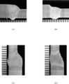
- FIG. 3 is a view showing a cross-sectional macro of a test piece, in which (A) is a first comparative example, (B) is a second comparative example, (C) is a first test piece, and (D) is a second Two test pieces are shown.
- the scale of the scale shown in each figure is 1 mm.
- the first comparative example is a conventional downward welding in the case of a gap of 0 mm
- the second comparative example is a conventional downward welding in the case of a gap of 1 mm
- the first test piece is transverse welding in the case of a gap of 0 mm.
- All of them are hybrid welded under the same conditions while laser welding is preceded and arc welding is followed.
- the hybrid welding device and the hybrid welding method according to the present embodiment described above laser welding is preceded and arc welding is performed laterally while the first joint J1 and the second joint J2 are arranged vertically. Therefore, the base material (molten metal) melted by the preceding laser welding can be dropped by its own weight. Therefore, even in the case where there is a gap ⁇ g between the first joint J1 and the second joint J2, the gap ⁇ g can be embedded with the molten base material (molten metal), and the deposited metal is not dropped. It can be effectively arc welded.
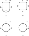
- FIG. 4 is a cross-sectional view showing an example of a workpiece to be welded, in which (A) is a first example, (B) is a second example, (C) is a third example, and (D) is a third example.
- the fourth example is shown.
- the work 4 shown in FIG. 4A shows, for example, a cylindrical steel material such as a boom or a jib used for a crane truck, a high-altitude work vehicle or the like.
- the work 4 is divided into upper and lower parts with respect to the posture in use, the upper work 41 has an angular U-shaped cross section, and the lower work 42 has a round U-shaped cross section .
- the thickness of the lower work 42 is larger than the thickness of the upper work 41.
- the first joint J 1 is constituted by both ends of the upper work 41
- the second joint J 2 is constituted by both ends of the lower work 42.
- the workpiece 4 shown in FIG. 4 (B) shows, for example, a hollow substantially square pole-shaped steel material used for a column or the like of a steel structure.
- the workpiece 4 is divided into two along the longitudinal direction, and at the time of welding, one is disposed on the upper side to be the upper workpiece 41 and the other is disposed on the lower side to be the lower workpiece 42.
- the upper work 41 and the lower work 42 have the same shape, and each have an angular U-shaped cross section.
- the first joint J 1 is constituted by both ends of the upper work 41
- the second joint J 2 is constituted by both ends of the lower work 42.
- the workpiece 4 shown in FIG. 4C is, for example, a hollow cylindrical steel material used for piping or the like.
- the workpiece 4 is divided into two along the longitudinal direction, and at the time of welding, one is disposed on the upper side to be the upper workpiece 41 and the other is disposed on the lower side to be the lower workpiece 42.
- the upper work 41 and the lower work 42 have the same shape, and each have a semicircular cross section.
- the first joint J 1 is constituted by both ends of the upper work 41
- the second joint J 2 is constituted by both ends of the lower work 42.
- work 4 mentioned above is a mere example, and is not limited to these shapes. That is, the first joint J1 is constituted by both ends in a cross section of a steel material having a substantially U-shaped or substantially semicircular cross section, and the second joint J2 is opposed to both ends of the first joint J1. What is necessary is just to be comprised by the steel materials which have the equipped cross section.
- the work 4 shown in FIG. 4D is, for example, a hollow cylindrical steel material used for piping or the like.
- the workpiece 4 is formed by bending a long steel plate into a circular shape, and at the time of welding, the joints at both ends are disposed in the horizontal direction.
- the first joint J1 is constituted by the end of the steel plate disposed on the upper side
- the second joint J2 is constituted by the end of the steel plate disposed on the lower side.
- the work 4 may have a weld only on one side in the longitudinal direction.
- FIG. 5 is a view showing a hybrid welding method according to another embodiment of the present invention, in which (A) shows a second embodiment and (B) shows a third embodiment.
- the drawings of the laser welding device 2 and the arc welding device 3 are simplified.
- the hybrid welding apparatus 1 performing these welding methods includes moving means 5 for moving the laser head 21 and the welding torch 31 in the horizontal direction along the work 4.
- the moving means 5 includes rails 51 disposed in parallel on both sides of the work 4 and a carriage 52 traveling on the rails 51.
- the carriage 52 includes a support member 53 for supporting the laser head 21 and the welding torch 31, and a drive motor 54 for causing the carriage 52 to self-propelled.
- the driving means of the carriage 52 is not limited to the illustrated configuration.
- the carriages 52 disposed on the left and right sides of the work 4 are set on the same side (left side in the drawing) on the rail 51 and synchronized in the same direction while synchronizing. Be moved.
- the carriages 52 disposed on the left and right sides of the work 4 are set on the opposite side (left and right sides in the drawing) on the rail 51 and Moved in the direction.
- the welding time can be shortened, and the deformation at the heat input at the time of welding the work 4 can be reduced. it can.
- the moving means 5 having the rail 51 and the carriage 52 may be disposed only on one side of the work 4.
Landscapes
- Engineering & Computer Science (AREA)
- Physics & Mathematics (AREA)
- Optics & Photonics (AREA)
- Plasma & Fusion (AREA)
- Mechanical Engineering (AREA)
- Chemical & Material Sciences (AREA)
- Materials Engineering (AREA)
- Laser Beam Processing (AREA)
- Arc Welding In General (AREA)
Abstract
母材間に隙間を有する突合せ溶接の場合であっても、溶着金属を落下させずに溶接することができる、ハイブリッド溶接方法及びハイブリッド溶接装置を提供する。 本発明に係るハイブリッド溶接装置1は、レーザ溶接とアーク溶接とを併用して第一継手J1と第二継手J2とを突合せ溶接するハイブリッド溶接装置であって、溶接部にレーザ光Lを照射するレーザヘッド21を備えたレーザ溶接装置2と、溶接部に溶加材Wを供給する溶接トーチ31を備えたアーク溶接装置3と、を備え、レーザヘッド21は、横向き溶接可能かつ溶接方向の上流側に配置され、溶接トーチ31は、横向き溶接可能かつ溶接方向の下流側に配置されており、溶接線が略水平となるように第一継手J1及び第二継手J2を上下に配置した状態で横向きに溶接するように構成されている。
Description
本発明は、ハイブリッド溶接方法及びハイブリッド溶接装置に関し、特に、母材間に隙間を有する突合せ溶接に適したハイブリッド溶接方法及びハイブリッド溶接装置に関する。
例えば、クレーン車、高所作業車、橋梁点検車等の構成部品であるブームは、中空の筒形状を有する長尺の鋼構造物である。かかるブームは、近年、断面略U字形状を有する鋼材の開放側の両端部同士を突合せ溶接することによって長尺の筒形状に形成されている。
例えば、特許文献1には、断面U字状に曲げ加工した長尺の高張力鋼板である上鋼板と、当該上鋼板よりも大きな曲げ半径で断面U字状に曲げ加工し前記上鋼板よりも板厚が厚い長尺の高張力鋼板である下鋼板を、それぞれ端面で溶接して断面筒型のブームを製作する溶接方法であって、前記上鋼板と前記下鋼板の端縁同士の突合せ接合部分が、裏当て金を用いることなく、アーク溶接が先行しレーザ溶接が後行するハイブリッド溶接で溶接され、先行する前記アーク溶接では、前記上鋼板と前記下鋼板の突合せ表面部を溶融して、母材の溶融金属に溶加材の溶融金属を加え、後行する前記レーザ溶接で前記溶融金属と突合せ接合部分の両方の母材を接合部の深さ方向に溶け込ませることを特徴とするブームの溶接方法が開示されている。
しかしながら、溶接線の鉛直上方から溶接を行う下向き溶接において、アーク溶接を先行させ、レーザ溶接を後行させた場合には、アーク溶接時に生成した溶着金属にレーザ光が照射されることから、溶着金属がレーザ光によって押されて落下してしまうという問題が生じる。特に、母材間に隙間を有する突合せ溶接の場合に、溶着金属が落下しやすい。また、このような溶着金属の落下現象を抑制するには、結局、裏当て材が必要になってしまう。
本発明はかかる問題点に鑑み創案されたものであり、母材間に隙間を有する突合せ溶接の場合であっても、溶着金属を落下させずに溶接することができる、ハイブリッド溶接方法及びハイブリッド溶接装置を提供することを目的とする。
本発明によれば、レーザ溶接とアーク溶接とを併用して第一継手と第二継手とを突合せ溶接するハイブリッド溶接方法において、前記第一継手及び前記第二継手を上下に配置した状態で、前記レーザ溶接を先行させ、前記アーク溶接を後行させながら横向きに溶接する、ことを特徴とするハイブリッド溶接方法が提供される。
前記第一継手及び前記第二継手は、溶接線に沿って少なくとも一部に隙間を有していてもよい。
前記ハイブリッド溶接方法は、前記レーザ溶接によって溶融した母材で前記隙間を埋め込みながら前記アーク溶接を行うようにしてもよい。
また、前記レーザ溶接に使用されるレーザ光の光径は、前記隙間の最大値より大きく設定され、前記アーク溶接に使用される溶加材の直径は、前記隙間の最大値より小さく設定されていてもよい。
また、前記レーザ溶接時におけるレーザ光の入射角度は、例えば、略90°である。
また、前記第一継手及び前記第二継手のうち板厚の大きい方を下側に配置するようにしてもよい。
また、前記第一継手は、略U字形状又は略半円形状の断面を有する鋼材の断面における両端部によって構成され、前記第二継手は、前記第一継手の前記両端部と対峙する両端部を備えた断面を有する鋼材によって構成されていてもよい。このとき、前記鋼材の左右に位置する二つの溶接線を同一方向に向かって同時に溶接してもよいし、前記鋼材の左右に位置する二つの溶接線を反対方向に向かって同時に溶接するようにしてもよい。
また、本発明によれば、レーザ溶接とアーク溶接とを併用して第一継手と第二継手とを突合せ溶接するハイブリッド溶接装置において、溶接部にレーザ光を照射するレーザヘッドと、溶接部に溶加材を供給する溶接トーチと、を含み、前記レーザヘッドは、横向き溶接可能かつ溶接方向の上流側に配置され、前記溶接トーチは、横向き溶接可能かつ溶接方向の下流側に配置されており、前記第一継手及び前記第二継手を上下に配置した状態で横向きに溶接する、ことを特徴とするハイブリッド溶接装置が提供される。
上述した本発明に係るハイブリッド溶接方法及びハイブリッド溶接装置によれば、先行するレーザ溶接によって溶融した母材(溶融金属)を自重により落とし込むことによって、第一継手と第二継手との間に隙間を有する場合であっても、その隙間を溶融した母材(溶融金属)で埋め込むことができ、溶着金属を落下させずに効果的にアーク溶接することができる。
以下、本発明の実施形態について、図1~図5(B)を用いて説明する。ここで、図1は、本発明の一実施形態に係るハイブリッド溶接装置の全体構成を示す平面図である。図2は、本発明の第一実施形態に係るハイブリッド溶接方法の原理を示す断面図であり、(A)は初期状態、(B)はアーク溶接前の状態、(C)は溶接完了後の状態、を示している。
本発明の一実施形態に係るハイブリッド溶接装置1は、例えば、図1に示したように、レーザ溶接とアーク溶接とを併用して第一継手J1と第二継手J2とを突合せ溶接するハイブリッド溶接装置であって、溶接部にレーザ光Lを照射するレーザヘッド21を備えたレーザ溶接装置2と、溶接部に溶加材Wを供給する溶接トーチ31を備えたアーク溶接装置3と、を備え、レーザヘッド21は、横向き溶接可能かつ溶接方向の上流側に配置され、溶接トーチ31は、横向き溶接可能かつ溶接方向の下流側に配置されており、第一継手J1及び第二継手J2を上下に配置した状態で横向きに溶接するように構成されている。
ここで、説明の便宜上、図1及び図2(A)に示したように、溶接線に沿った方向にX軸を設定し、X軸に垂直な水平方向にY軸を設定し、鉛直方向にZ軸を設定する。
レーザ溶接装置2は、例えば、レーザヘッド21と、レーザ光を生成するレーザ発振器22と、レーザ光をレーザ発振器22からレーザヘッド21に搬送する光ファイバ23と、を備えている。なお、図示しないが、レーザ溶接装置2は、レーザヘッド21を所定の位置に固定する固定手段やレーザヘッド21を移動可能に支持するロボットアームを備えていてもよい。
レーザヘッド21は、例えば、レーザ光Lが溶接部に垂直に照射されるように位置決めされる。すなわち、XY平面におけるレーザ光Lの入射角αは約90°に設定される。このように、レーザ光Lを垂直に照射した場合であっても、溶接部に隙間が形成されている場合にはレーザ光Lの反射量が少なく、レーザ光Lによって溶融した母材(溶融金属)によってレーザ光Lが吸収されることから、レーザ光Lの反射光によるレーザヘッド21の損傷は少ない。なお、レーザ光Lの入射角αは90°より小さい角度に設定してもよい。
アーク溶接装置3は、例えば、溶接トーチ31と、溶加材W(溶接ワイヤ)をコイル状に巻いた溶接ワイヤドラム32と、溶接ワイヤドラム32から溶接トーチ31に溶加材Wを送り出す溶接ワイヤ送給装置33と、を備えている。なお、図示しないが、アーク溶接装置3は、溶接トーチ31を所定の位置に固定する固定手段や溶接部にシールドガスを供給するシールドガス供給手段を備えていてもよい。
溶接トーチ31は、例えば、XY平面における溶加材Wの入射角βが45°程度となるように位置決めされる。また、溶接トーチ31は、YZ平面に対して平行な状態に位置決めされていてもよいし、YZ平面に対して傾斜した状態に位置決めされていてもよい。
また、図1に示したように、レーザ溶接装置2は、アーク溶接装置3よりも溶接方向(X軸方向)の上流側に配置されている。すなわち、レーザヘッド21は、溶接トーチ31よりも溶接方向(X軸方向)の上流側に配置されている。したがって、本実施形態に係るハイブリッド溶接装置1は、レーザ溶接とアーク溶接とを併用したハイブリッド溶接において、レーザ溶接を先行させ、アーク溶接を後行させるように構成されている。
第一継手J1及び第二継手J2は、例えば、所定の形状を有する鋼板である。図2(A)に示したように、第一継手J1及び第二継手J2は、第二継手J2を下方に配置し、第一継手J1を上方に配置した状態で突合せ溶接される。また、第二継手J2の板厚D2は、第一継手J1の板厚D1よりも大きいものとする。すなわち、本実施形態では、第一継手J1及び第二継手J2のうち板厚の大きい方を下側に配置している。
また、第一継手J1及び第二継手J2は、鋼板によって形成されていることから、少なからず加工誤差や変形等を有しており、図2(A)に示したように、溶接部のZ軸方向に隙間Δgが形成されることがある。この隙間Δgを有する溶接部に横向き(Y軸方向)にレーザ光Lが照射されると、図2(B)に示したように、第一継手J1の母材が溶融し、自重により下方に垂れ落ちることとなる。したがって、第一継手J1と第二継手J2との間に形成された隙間Δgは、レーザ光Lによって溶融した母材(溶融金属)により埋め込まれる。
本実施形態では、第一継手J1の溶融した母材(溶融金属)を第二継手J2の端部の上に垂れ落としていることから、その受け皿を構成する観点において、第二継手J2の板厚D2は第一継手J1の板厚D1よりも大きいことが好ましい。なお、必要に応じて、第二継手J2の板厚D2は第一継手J1の板厚D1と同じ大きさであってもよいし、第二継手J2の板厚D2は第一継手J1の板厚D1よりも小さくてもよいことは勿論である。
このように、レーザ溶接を先行させることにより、隙間Δgを溶融した母材(溶融金属)で埋め込みながらアーク溶接することができ、図2(C)に示したように、溶接欠陥の少ないきれいなビードを形成することができる。
また、レーザ光Lは、溶接部に照射されたときに少なくとも第一継手J1の下端を加熱する必要があることから、レーザ光Lの光径は溶接線上における隙間Δgの最大値より大きく設定される。一方、アーク溶接時には隙間Δgは狭まっていることから、溶加材Wの直径は隙間Δgの最大値より小さく設定されていてもよい。
ここで、図3は、試験片の断面マクロを示す図であり、(A)は第一比較例、(B)は第二比較例、(C)は第一試験片、(D)は第二試験片、を示している。なお、各図に示したスケールの目盛は1mmである。
第一比較例は従来の下向き溶接で隙間0mmの場合、第二比較例は従来の下向き溶接で隙間1mmの場合、第一試験片は横向き溶接で隙間0mmの場合、第二試験片は横向き溶接で隙間1mmの場合、を示している。いずれもレーザ溶接を先行させアーク溶接を後行させながら同じ条件でハイブリッド溶接したものである。
上述した特許文献1に記載された発明のように、下向き溶接でアーク溶接を先行させレーザ溶接を後行させた場合には、溶着金属がレーザ光によって落下し、溶接不良を生じる。また、第一比較例及び第二比較例のように、下向き溶接でレーザ溶接を先行させた場合であっても、図3(A)及び図3(B)に示したように、裏側にビードが大きく突出したり、表側にアンダーカットやアンダーフィル等の溶接欠陥を生じたりすることとなる。
ビードが大きく突出した場合には、その部分を機械加工する必要があり、作業工程及び作業時間が増加してしまう。また、溶接欠陥を生じた場合には、手作業で溶接欠陥を修正しなければならない。
それに対して、本実施形態のように、横向き溶接でレーザ溶接を先行させた場合には、図3(C)及び図3(D)に示したように、裏側に突出するビードの膨らみを小さくすることができ、表側のビードにおいてもアンダーカットやアンダーフィル等の溶接欠陥のない高品質な溶接を行うことができる。
上述した本実施形態に係るハイブリッド溶接装置及びハイブリッド溶接方法によれば、第一継手J1及び第二継手J2を上下に配置した状態で、レーザ溶接を先行させアーク溶接を後行させながら横向きに溶接していることから、先行するレーザ溶接によって溶融した母材(溶融金属)を自重により落とし込むことができる。したがって、第一継手J1と第二継手J2との間に隙間Δgを有する場合であっても、その隙間Δgを溶融した母材(溶融金属)で埋め込むことができ、溶着金属を落下させずに効果的にアーク溶接することができる。
次に、本実施形態に係るハイブリッド溶接方法によって溶接されるワーク4の形状について説明する。ここで、図4は、溶接対象物であるワークの一例を示す断面図であり、(A)は第一例、(B)は第二例、(C)は第三例、(D)は第四例、を示している。
図4(A)に示したワーク4は、例えば、クレーン車や高所作業車等に使用されるブームやジブ等の筒型の鋼材を示したものである。ワーク4は、使用時の姿勢に対して上下に二分割されており、上側ワーク41は角張ったU字形状の断面を有し、下側ワーク42は丸いU字形状の断面を有している。一般に、下側ワーク42の板厚は、上側ワーク41の板厚よりも大きく形成されている。第一継手J1は、上側ワーク41の両端部によって構成され、第二継手J2は、下側ワーク42の両端部によって構成される。
図4(B)に示したワーク4は、例えば、鋼構造物の柱等に使用される中空の略四角柱形状の鋼材を示したものである。ワーク4は、長手方向に沿って二分割されており、溶接時には、一方を上側に配置して上側ワーク41とし、他方を下側に配置して下側ワーク42とする。上側ワーク41及び下側ワーク42は、同じ形状を有しており、それぞれ角張ったU字形状の断面を有している。第一継手J1は、上側ワーク41の両端部によって構成され、第二継手J2は、下側ワーク42の両端部によって構成される。
図4(C)に示したワーク4は、例えば、配管等に使用される中空の円筒形状の鋼材を示したものである。ワーク4は、長手方向に沿って二分割されており、溶接時には、一方を上側に配置して上側ワーク41とし、他方を下側に配置して下側ワーク42とする。上側ワーク41及び下側ワーク42は、同じ形状を有しており、それぞれ半円形状の断面を有している。第一継手J1は、上側ワーク41の両端部によって構成され、第二継手J2は、下側ワーク42の両端部によって構成される。
なお、上述したワーク4は単なる一例であり、これらの形状に限定されるものではない。すなわち、第一継手J1は、略U字形状又は略半円形状の断面を有する鋼材の断面における両端部によって構成され、第二継手J2は、第一継手J1の両端部と対峙する両端部を備えた断面を有する鋼材によって構成されていればよい。
また、図4(D)に示したワーク4は、例えば、配管等に使用される中空の円筒形状の鋼材を示したものである。ワーク4は、長尺の鋼板を円形状に折り曲げて形成されており、溶接時には、両端の継ぎ目を横向きに配置する。第一継手J1は、上側に配置される鋼板の端部によって構成され、第二継手J2は、下側に配置される鋼板の端部によって構成される。このように、ワーク4は、長手方向の片側にのみ溶接部を有するものであってもよい。
次に、図4(A)に示したワーク4のように、鋼材の左右両側に溶接部を有する場合における溶接方法について説明する。ここで、図5は、本発明の他の実施形態に係るハイブリッド溶接方法を示す図であり、(A)は第二実施形態、(B)は第三実施形態、を示している。なお、各図において、レーザ溶接装置2及びアーク溶接装置3の図は簡略化してある。
図5(A)に示した第二実施形態に係る溶接方法は、ワーク4の左右に位置する二つの溶接線を同一方向に向かって同時に溶接するようにしたものである。また、図5(B)に示した第三実施形態に係る溶接方法は、ワーク4の左右に位置する二つの溶接線を反対方向に向かって同時に溶接するようにしたものである。これらの溶接方法を行うハイブリッド溶接装置1は、レーザヘッド21及び溶接トーチ31をワーク4に沿って水平方向に移動させる移動手段5を備えている。
移動手段5は、ワーク4の両側に平行に配置されたレール51と、レール51上を走行する台車52と、を備えている。台車52は、レーザヘッド21及び溶接トーチ31を支持する支持部材53と、台車52を自走させる駆動モータ54と、を備えている。なお、台車52の駆動手段は図示した構成に限定されるものではない。
図5(A)に示した第二実施形態では、ワーク4の左右両側に配置された台車52は、レール51上の同じ側(図の左側)にセットされており、同期させながら同じ方向に移動される。図5(B)に示した第三実施形態では、ワーク4の左右両側に配置された台車52は、レール51上の反対側(図の左側と右側)にセットされており、同期させながら反対方向に移動される。
このように、ワーク4の左右両側に配置された溶接部を横向き溶接で同時に溶接することにより、溶接時間を短縮することができるとともに、ワーク4の溶接時の入熱における変形を低減することができる。なお、片側にのみ溶接部を有するワーク4の場合には、レール51及び台車52を有する移動手段5をワーク4の片側にのみ配置すればよい。
本発明は、上述した実施形態に限定されず、本発明の趣旨を逸脱しない範囲で種々変更が可能であることは勿論である。
1 ハイブリッド溶接装置
2 レーザ溶接装置
3 アーク溶接装置
4 ワーク
5 移動手段
21 レーザヘッド
22 レーザ発振器
23 光ファイバ
31 溶接トーチ
32 溶接ワイヤドラム
33 溶接ワイヤ送給装置
41 上側ワーク
42 下側ワーク
51 レール
52 台車
53 支持部材
54 駆動モータ
J1 第一継手
J2 第二継手
2 レーザ溶接装置
3 アーク溶接装置
4 ワーク
5 移動手段
21 レーザヘッド
22 レーザ発振器
23 光ファイバ
31 溶接トーチ
32 溶接ワイヤドラム
33 溶接ワイヤ送給装置
41 上側ワーク
42 下側ワーク
51 レール
52 台車
53 支持部材
54 駆動モータ
J1 第一継手
J2 第二継手
Claims (10)
- レーザ溶接とアーク溶接とを併用して第一継手と第二継手とを突合せ溶接するハイブリッド溶接方法において、
前記第一継手及び前記第二継手を上下に配置した状態で、前記レーザ溶接を先行させ、前記アーク溶接を後行させながら横向きに溶接する、
ことを特徴とするハイブリッド溶接方法。 - 前記第一継手及び前記第二継手は、溶接線に沿って少なくとも一部に隙間を有する、ことを特徴とする請求項1に記載のハイブリッド溶接方法。
- 前記レーザ溶接によって溶融した母材で前記隙間を埋め込みながら前記アーク溶接を行う、ことを特徴とする請求項2に記載のハイブリッド溶接方法。
- 前記レーザ溶接に使用されるレーザ光の光径は、前記隙間の最大値より大きく設定され、前記アーク溶接に使用される溶加材の直径は、前記隙間の最大値より小さく設定されている、ことを特徴とする請求項2に記載のハイブリッド溶接方法。
- 前記レーザ溶接時におけるレーザ光の入射角度は略90°である、ことを特徴とする請求項1に記載のハイブリッド溶接方法。
- 前記第一継手及び前記第二継手のうち板厚の大きい方を下側に配置する、ことを特徴とする請求項1に記載のハイブリッド溶接方法。
- 前記第一継手は、略U字形状又は略半円形状の断面を有する鋼材の断面における両端部によって構成され、前記第二継手は、前記第一継手の前記両端部と対峙する両端部を備えた断面を有する鋼材によって構成されている、ことを特徴とする請求項1に記載のハイブリッド溶接方法。
- 前記鋼材の左右に位置する二つの溶接線を同一方向に向かって同時に溶接する、ことを特徴とする請求項7に記載のハイブリッド溶接方法。
- 前記鋼材の左右に位置する二つの溶接線を反対方向に向かって同時に溶接する、ことを特徴とする請求項7に記載のハイブリッド溶接方法。
- レーザ溶接とアーク溶接とを併用して第一継手と第二継手とを突合せ溶接するハイブリッド溶接装置において、
溶接部にレーザ光を照射するレーザヘッドと、
溶接部に溶加材を供給する溶接トーチと、を含み、
前記レーザヘッドは、横向き溶接可能かつ溶接方向の上流側に配置され、
前記溶接トーチは、横向き溶接可能かつ溶接方向の下流側に配置されており、
前記第一継手及び前記第二継手を上下に配置した状態で横向きに溶接する、
ことを特徴とするハイブリッド溶接装置。
Priority Applications (3)
| Application Number | Priority Date | Filing Date | Title |
|---|---|---|---|
| CN201880053286.6A CN110997219B (zh) | 2017-08-24 | 2018-08-23 | 复合焊接方法及复合焊接装置 |
| EP18847454.8A EP3674031A4 (en) | 2017-08-24 | 2018-08-23 | HYBRID WELDING PROCESS AND HYBRID WELDING DEVICE |
| US16/640,860 US20210162538A1 (en) | 2017-08-24 | 2018-08-23 | Hybrid welding method and hybrid welding apparatus |
Applications Claiming Priority (2)
| Application Number | Priority Date | Filing Date | Title |
|---|---|---|---|
| JP2017-160787 | 2017-08-24 | ||
| JP2017160787A JP6722625B2 (ja) | 2017-08-24 | 2017-08-24 | ハイブリッド溶接方法及びハイブリッド溶接装置 |
Publications (1)
| Publication Number | Publication Date |
|---|---|
| WO2019039529A1 true WO2019039529A1 (ja) | 2019-02-28 |
Family
ID=65438924
Family Applications (1)
| Application Number | Title | Priority Date | Filing Date |
|---|---|---|---|
| PCT/JP2018/031087 Ceased WO2019039529A1 (ja) | 2017-08-24 | 2018-08-23 | ハイブリッド溶接方法及びハイブリッド溶接装置 |
Country Status (5)
| Country | Link |
|---|---|
| US (1) | US20210162538A1 (ja) |
| EP (1) | EP3674031A4 (ja) |
| JP (1) | JP6722625B2 (ja) |
| CN (1) | CN110997219B (ja) |
| WO (1) | WO2019039529A1 (ja) |
Families Citing this family (3)
| Publication number | Priority date | Publication date | Assignee | Title |
|---|---|---|---|---|
| EP4005724B1 (en) * | 2019-07-24 | 2025-04-09 | IHI Infrastructure Systems Co., Ltd. | Repairing laser welding method and use of a laser welding device for repairing |
| CN114012265B (zh) * | 2021-09-27 | 2023-05-12 | 华北水利水电大学 | 一种双束激光电弧复合单面横焊方法及装置 |
| CN113996932B (zh) * | 2021-11-15 | 2023-05-16 | 哈焊国创(青岛)焊接工程创新中心有限公司 | 一种消除焊缝余高及咬边缺陷的焊接系统及焊接方法 |
Citations (4)
| Publication number | Priority date | Publication date | Assignee | Title |
|---|---|---|---|---|
| JPH10505791A (ja) * | 1994-09-23 | 1998-06-09 | フラウンホーファー−ゲゼルシャフト ツル フェルデルング デル アンゲヴァンテン フォルシュング エー ファウ | 工作物を溶接する方法 |
| JPH10216972A (ja) * | 1997-02-04 | 1998-08-18 | Kubota Corp | レ−ザと消耗電極式ア−クの複合溶接方法 |
| US20140124486A1 (en) * | 2011-04-15 | 2014-05-08 | Terry Devers | Laser Welding Assembly And Method |
| JP6085010B2 (ja) | 2015-07-22 | 2017-02-22 | 株式会社タダノ | ブームの溶接方法 |
Family Cites Families (8)
| Publication number | Priority date | Publication date | Assignee | Title |
|---|---|---|---|---|
| US2737565A (en) * | 1953-11-03 | 1956-03-06 | Graver Tank & Mfg Co Inc | Welding tool manipulator |
| US6023043A (en) * | 1996-05-10 | 2000-02-08 | Mitsubishi Heavy Industries, Ltd. | Method of welding in the horizontal position and welding apparatus therefor |
| DE102004019448A1 (de) * | 2004-04-19 | 2005-11-10 | Muhr Und Bender Kg | Hybrid hergestelltes Blechelement und Verfahren zu seiner Herstellung |
| JP2007260716A (ja) * | 2006-03-28 | 2007-10-11 | Jfe Steel Kk | 変形能に優れた超高強度溶接鋼管の製造方法 |
| CN102922153B (zh) * | 2012-11-27 | 2014-10-15 | 哈尔滨工业大学 | 一种激光引导gmaw电弧复合横向焊接方法 |
| CN103071935B (zh) * | 2013-01-04 | 2015-05-27 | 哈尔滨工程大学 | 基于热输入控制的激光与电弧复合焊接装置及焊接方法 |
| EP2942143B1 (en) * | 2014-05-09 | 2017-03-15 | Gestamp HardTech AB | Methods for joining two blanks and blanks and products obtained |
| AU2016282010B2 (en) * | 2015-06-22 | 2018-12-06 | Kawasaki Jukogyo Kabushiki Kaisha | Double-side submerged arc welding method |
-
2017
- 2017-08-24 JP JP2017160787A patent/JP6722625B2/ja active Active
-
2018
- 2018-08-23 US US16/640,860 patent/US20210162538A1/en not_active Abandoned
- 2018-08-23 EP EP18847454.8A patent/EP3674031A4/en active Pending
- 2018-08-23 CN CN201880053286.6A patent/CN110997219B/zh active Active
- 2018-08-23 WO PCT/JP2018/031087 patent/WO2019039529A1/ja not_active Ceased
Patent Citations (4)
| Publication number | Priority date | Publication date | Assignee | Title |
|---|---|---|---|---|
| JPH10505791A (ja) * | 1994-09-23 | 1998-06-09 | フラウンホーファー−ゲゼルシャフト ツル フェルデルング デル アンゲヴァンテン フォルシュング エー ファウ | 工作物を溶接する方法 |
| JPH10216972A (ja) * | 1997-02-04 | 1998-08-18 | Kubota Corp | レ−ザと消耗電極式ア−クの複合溶接方法 |
| US20140124486A1 (en) * | 2011-04-15 | 2014-05-08 | Terry Devers | Laser Welding Assembly And Method |
| JP6085010B2 (ja) | 2015-07-22 | 2017-02-22 | 株式会社タダノ | ブームの溶接方法 |
Also Published As
| Publication number | Publication date |
|---|---|
| EP3674031A1 (en) | 2020-07-01 |
| EP3674031A4 (en) | 2021-05-19 |
| JP6722625B2 (ja) | 2020-07-15 |
| JP2019038004A (ja) | 2019-03-14 |
| CN110997219A (zh) | 2020-04-10 |
| CN110997219B (zh) | 2021-12-07 |
| US20210162538A1 (en) | 2021-06-03 |
Similar Documents
| Publication | Publication Date | Title |
|---|---|---|
| US11801573B2 (en) | Tack welding method and tack welding apparatus | |
| JPWO2010123035A1 (ja) | ハイブリッド溶接方法及びハイブリッド溶接装置 | |
| CN105149786A (zh) | 一种基于预制焊材的窄间隙激光扫描多层自熔焊接方法 | |
| JP6391412B2 (ja) | レーザ溶接方法及びレーザ溶接装置 | |
| KR20160021827A (ko) | 고온 와이어 tig 위치설정된 열 제어를 위한 시스템 및 용접 방법 | |
| CN105880829B (zh) | 激光焊接方法 | |
| US20120234798A1 (en) | Cladding application method and apparatus using hybrid laser process | |
| WO2019039529A1 (ja) | ハイブリッド溶接方法及びハイブリッド溶接装置 | |
| US20260034610A1 (en) | Repairing laser welding method and repairing laser welding device | |
| JP2021167026A (ja) | 溶接部欠陥の補修方法 | |
| JP6092163B2 (ja) | 溶接装置及び溶接方法 | |
| JP6215655B2 (ja) | レーザ溶接方法、それを用いた溶接継手の製造方法 | |
| CN104646831B (zh) | 用于空间偏移部件的复合焊接设备、系统和方法 | |
| JP7132550B2 (ja) | 突き合わせ溶接方法 | |
| JP2000176663A (ja) | 溶接方法 | |
| JP2009248104A (ja) | 溶接ビード整形方法 | |
| JP7294565B1 (ja) | 突合せレーザビーム溶接方法 | |
| JP7185192B2 (ja) | 上向き突き合わせ溶接方法及び上向き突き合わせ溶接台車 | |
| WO2020054309A1 (ja) | 突き合わせ溶接台車及び突き合わせ溶接方法 | |
| KR20120073954A (ko) | 미세 튜브의 제조 장치 | |
| KR101160981B1 (ko) | 플럭스 코어드 와이어 제조 장치 | |
| JP2011200890A (ja) | レーザー溶接方法 | |
| JP4998633B1 (ja) | レーザ溶接方法 | |
| JP2013116478A (ja) | レーザ溶接方法 | |
| JP2006346709A (ja) | 薄板縁継手のレーザ溶接方法 |
Legal Events
| Date | Code | Title | Description |
|---|---|---|---|
| 121 | Ep: the epo has been informed by wipo that ep was designated in this application |
Ref document number: 18847454 Country of ref document: EP Kind code of ref document: A1 |
|
| NENP | Non-entry into the national phase |
Ref country code: DE |
|
| ENP | Entry into the national phase |
Ref document number: 2018847454 Country of ref document: EP Effective date: 20200324 |