WO2019043991A1 - アブレーションシステム - Google Patents
アブレーションシステム Download PDFInfo
- Publication number
- WO2019043991A1 WO2019043991A1 PCT/JP2018/005775 JP2018005775W WO2019043991A1 WO 2019043991 A1 WO2019043991 A1 WO 2019043991A1 JP 2018005775 W JP2018005775 W JP 2018005775W WO 2019043991 A1 WO2019043991 A1 WO 2019043991A1
- Authority
- WO
- WIPO (PCT)
- Prior art keywords
- ablation
- power supply
- breaks
- control unit
- threshold
- Prior art date
- Legal status (The legal status is an assumption and is not a legal conclusion. Google has not performed a legal analysis and makes no representation as to the accuracy of the status listed.)
- Ceased
Links
Images


Classifications
-
- A—HUMAN NECESSITIES
- A61—MEDICAL OR VETERINARY SCIENCE; HYGIENE
- A61B—DIAGNOSIS; SURGERY; IDENTIFICATION
- A61B18/00—Surgical instruments, devices or methods for transferring non-mechanical forms of energy to or from the body
- A61B18/04—Surgical instruments, devices or methods for transferring non-mechanical forms of energy to or from the body by heating
- A61B18/12—Surgical instruments, devices or methods for transferring non-mechanical forms of energy to or from the body by heating by passing a current through the tissue to be heated, e.g. high-frequency current
- A61B18/14—Probes or electrodes therefor
- A61B18/1477—Needle-like probes
-
- A—HUMAN NECESSITIES
- A61—MEDICAL OR VETERINARY SCIENCE; HYGIENE
- A61B—DIAGNOSIS; SURGERY; IDENTIFICATION
- A61B18/00—Surgical instruments, devices or methods for transferring non-mechanical forms of energy to or from the body
- A61B18/04—Surgical instruments, devices or methods for transferring non-mechanical forms of energy to or from the body by heating
- A61B18/12—Surgical instruments, devices or methods for transferring non-mechanical forms of energy to or from the body by heating by passing a current through the tissue to be heated, e.g. high-frequency current
- A61B18/1206—Generators therefor
- A61B18/1233—Generators therefor with circuits for assuring patient safety
-
- A—HUMAN NECESSITIES
- A61—MEDICAL OR VETERINARY SCIENCE; HYGIENE
- A61B—DIAGNOSIS; SURGERY; IDENTIFICATION
- A61B18/00—Surgical instruments, devices or methods for transferring non-mechanical forms of energy to or from the body
- A61B2018/00005—Cooling or heating of the probe or tissue immediately surrounding the probe
- A61B2018/00011—Cooling or heating of the probe or tissue immediately surrounding the probe with fluids
- A61B2018/00023—Cooling or heating of the probe or tissue immediately surrounding the probe with fluids closed, i.e. without wound contact by the fluid
-
- A—HUMAN NECESSITIES
- A61—MEDICAL OR VETERINARY SCIENCE; HYGIENE
- A61B—DIAGNOSIS; SURGERY; IDENTIFICATION
- A61B18/00—Surgical instruments, devices or methods for transferring non-mechanical forms of energy to or from the body
- A61B2018/00315—Surgical instruments, devices or methods for transferring non-mechanical forms of energy to or from the body for treatment of particular body parts
- A61B2018/00529—Liver
-
- A—HUMAN NECESSITIES
- A61—MEDICAL OR VETERINARY SCIENCE; HYGIENE
- A61B—DIAGNOSIS; SURGERY; IDENTIFICATION
- A61B18/00—Surgical instruments, devices or methods for transferring non-mechanical forms of energy to or from the body
- A61B2018/00571—Surgical instruments, devices or methods for transferring non-mechanical forms of energy to or from the body for achieving a particular surgical effect
- A61B2018/00577—Ablation
-
- A—HUMAN NECESSITIES
- A61—MEDICAL OR VETERINARY SCIENCE; HYGIENE
- A61B—DIAGNOSIS; SURGERY; IDENTIFICATION
- A61B18/00—Surgical instruments, devices or methods for transferring non-mechanical forms of energy to or from the body
- A61B2018/00571—Surgical instruments, devices or methods for transferring non-mechanical forms of energy to or from the body for achieving a particular surgical effect
- A61B2018/00595—Cauterization
-
- A—HUMAN NECESSITIES
- A61—MEDICAL OR VETERINARY SCIENCE; HYGIENE
- A61B—DIAGNOSIS; SURGERY; IDENTIFICATION
- A61B18/00—Surgical instruments, devices or methods for transferring non-mechanical forms of energy to or from the body
- A61B2018/00636—Sensing and controlling the application of energy
- A61B2018/00642—Sensing and controlling the application of energy with feedback, i.e. closed loop control
-
- A—HUMAN NECESSITIES
- A61—MEDICAL OR VETERINARY SCIENCE; HYGIENE
- A61B—DIAGNOSIS; SURGERY; IDENTIFICATION
- A61B18/00—Surgical instruments, devices or methods for transferring non-mechanical forms of energy to or from the body
- A61B2018/00636—Sensing and controlling the application of energy
- A61B2018/00666—Sensing and controlling the application of energy using a threshold value
- A61B2018/00678—Sensing and controlling the application of energy using a threshold value upper
-
- A—HUMAN NECESSITIES
- A61—MEDICAL OR VETERINARY SCIENCE; HYGIENE
- A61B—DIAGNOSIS; SURGERY; IDENTIFICATION
- A61B18/00—Surgical instruments, devices or methods for transferring non-mechanical forms of energy to or from the body
- A61B2018/00636—Sensing and controlling the application of energy
- A61B2018/00696—Controlled or regulated parameters
- A61B2018/00702—Power or energy
- A61B2018/00708—Power or energy switching the power on or off
-
- A—HUMAN NECESSITIES
- A61—MEDICAL OR VETERINARY SCIENCE; HYGIENE
- A61B—DIAGNOSIS; SURGERY; IDENTIFICATION
- A61B18/00—Surgical instruments, devices or methods for transferring non-mechanical forms of energy to or from the body
- A61B2018/00636—Sensing and controlling the application of energy
- A61B2018/00696—Controlled or regulated parameters
- A61B2018/00714—Temperature
-
- A—HUMAN NECESSITIES
- A61—MEDICAL OR VETERINARY SCIENCE; HYGIENE
- A61B—DIAGNOSIS; SURGERY; IDENTIFICATION
- A61B18/00—Surgical instruments, devices or methods for transferring non-mechanical forms of energy to or from the body
- A61B2018/00636—Sensing and controlling the application of energy
- A61B2018/00696—Controlled or regulated parameters
- A61B2018/00744—Fluid flow
-
- A—HUMAN NECESSITIES
- A61—MEDICAL OR VETERINARY SCIENCE; HYGIENE
- A61B—DIAGNOSIS; SURGERY; IDENTIFICATION
- A61B18/00—Surgical instruments, devices or methods for transferring non-mechanical forms of energy to or from the body
- A61B2018/00636—Sensing and controlling the application of energy
- A61B2018/00773—Sensed parameters
- A61B2018/00875—Resistance or impedance
-
- A—HUMAN NECESSITIES
- A61—MEDICAL OR VETERINARY SCIENCE; HYGIENE
- A61B—DIAGNOSIS; SURGERY; IDENTIFICATION
- A61B18/00—Surgical instruments, devices or methods for transferring non-mechanical forms of energy to or from the body
- A61B2018/00636—Sensing and controlling the application of energy
- A61B2018/00898—Alarms or notifications created in response to an abnormal condition
-
- A—HUMAN NECESSITIES
- A61—MEDICAL OR VETERINARY SCIENCE; HYGIENE
- A61B—DIAGNOSIS; SURGERY; IDENTIFICATION
- A61B18/00—Surgical instruments, devices or methods for transferring non-mechanical forms of energy to or from the body
- A61B2018/0091—Handpieces of the surgical instrument or device
- A61B2018/00916—Handpieces of the surgical instrument or device with means for switching or controlling the main function of the instrument or device
- A61B2018/00922—Handpieces of the surgical instrument or device with means for switching or controlling the main function of the instrument or device by switching or controlling the treatment energy directly within the hand-piece
Definitions
- the present invention relates to an ablation system provided with an electrode needle which is percutaneously punctured with respect to an affected area in the body, and a power supply device for supplying electric power for ablation (cauterization).
- an ablation system As one of medical devices for treating an affected area in a patient's body (for example, an affected area having a tumor such as cancer), an ablation system has been proposed in which such affected area is ablated (eg, Patent Document 1) reference).
- the ablation system includes an electrode needle which is percutaneously punctured to an affected area in the body, and a power supply which supplies power for ablation of the affected area.
- an ablation system comprising: an electrode needle percutaneously pierced with respect to an affected area in a body; and a power supply for supplying power for ablation between the electrode needle and a return electrode. And a control unit for controlling the power supply operation of the power supply unit.
- the control unit measures an impedance value between the electrode needle and the return electrode at the time of ablation, and counts the number of breaks which is the number of break states in which the impedance value exceeds the first threshold. When the number of times reaches the second threshold, the ablation is automatically ended by automatically stopping the supply of power.
- the control unit counts the number of breaks, and when the number of breaks reaches the second threshold, the power supply unit automatically supplies power. Ablation is automatically terminated by stopping. Thereby, for example, as compared with the case where ablation is manually ended after visually checking the number of breaks, or when ablation is automatically terminated after a predetermined waiting time has elapsed without confirming the number of breaks, etc. Effective ablation can be performed easily.
- the power supply device may further include a display unit that displays a count value of the number of breaks.
- the operator or the like of the power supply apparatus can grasp the count value of the number of breaks as needed, which further improves the convenience.
- the control unit when the control unit is in the break state, the control unit counts the number of breaks and temporarily reduces or stops the supply of power, and the number of breaks is the number of breaks. If the second threshold is not reached, the supply of power may be automatically resumed (first operation mode). In this case (when the first operation mode is executed), the resumption of power supply is also performed automatically, so a series of processing from the start to the end of ablation is automatically performed. As a result, the convenience is further improved.
- control unit when the control unit is in a break state, it counts the number of breaks and temporarily reduces or stops the supply of power, and when the number of breaks does not reach the second threshold, The supply of power may be resumed based on an operation signal input in response to an operation by the operator (second operation mode).
- second operation mode when the second operation mode is performed, the restart of the power supply itself is performed manually, so that it is possible to adjust the restart timing of the power supply as needed, for example. Therefore, also in this case, the convenience can be further improved.
- the first operation mode and the second operation mode may be switchable. In this case, when the power supply is resumed, these two types of operation modes can be switched as needed according to, for example, the application, the situation, and the like, so that the convenience can be further improved.
- a liquid supply device for supplying a cooling liquid to the electrode needle is further provided, and the control unit determines that the number of breaks has reached the second threshold value.
- the supply of the liquid may be automatically stopped after the ablation is automatically ended.
- the liquid supply stop can be realized at an appropriate timing as compared with the case where the liquid supply is manually stopped after the end of the ablation.
- the control unit counts the number of breaks, and when the number of breaks reaches the second threshold, the power supply unit automatically supplies power. Since the ablation is automatically terminated by stopping it, effective ablation can be easily performed. Therefore, it is possible to improve the convenience when using the ablation system.
- FIG. 1 is a block diagram schematically showing an entire configuration example of an ablation system according to an embodiment of the present invention. It is a schematic diagram showing an example of the abduction condition in the affected part by ablation. It is a timing diagram which represents typically an example of the break state and the number of breaks in the case of ablation. It is a flow chart showing an example of processing of ablation concerning an embodiment. It is a schematic diagram showing an example of the display mode in the display part in the case of ablation shown in FIG.
- FIG. 5 is a diagram showing an example of an operation mode at the time of resumption of power supply shown in FIG.
- FIG. 1 is a schematic block diagram showing an example of the overall configuration of an ablation system (ablation system 5) according to an embodiment of the present invention.
- the ablation system 5 is a system used when treating an affected area 90 in the body of the patient 9, and performs predetermined ablation on such affected area 90.
- the affected part which has tumors such as cancer (a liver cancer, lung cancer, a breast cancer, a kidney cancer, a thyroid cancer etc.), is mentioned, for example.
- the ablation system 5 includes an electrode needle 1, a liquid supply device 2 and a power supply device 3 as shown in FIG. Further, in the case of ablation using this ablation system 5, for example, the return electrode plate 4 shown in FIG. 1 is also appropriately used.
- the electrode needle 1 is, for example, a needle that is percutaneously punctured with respect to an affected area 90 in the body of the patient 9, as indicated by an arrow P1 in FIG.
- the electrode needle 1 is used at the time of the above-described ablation, and has, for example, an electrode portion 11 and a covering portion 12 as shown in FIG.
- the liquid L supplied from the liquid supply apparatus 2 mentioned later circulates and flows inside such an electrode needle 1 (refer FIG. 1).
- the electrode portion 11 is a region portion of the needle-like structure constituting the electrode needle 1 which is not coated with an insulating coating, and is a portion functioning as an electrode at the time of ablation.
- the covering portion 12 is an area portion of the above-described needle-like structure on which the insulating covering is provided. As shown in FIG. 1, the electrode portion 11 is disposed in the vicinity of the tip of the electrode needle 1, and the covering portion 12 is disposed on the proximal end side of the electrode portion 11.
- the liquid supply device 2 is a device for supplying the liquid L for cooling to the electrode needle 1 described above, and includes, for example, a liquid supply unit 21 as shown in FIG.
- a liquid supply unit 21 as shown in FIG.
- the liquid L for cooling for example, sterile water, sterile saline and the like can be mentioned.
- the liquid supply unit 21 supplies the above-described liquid L to the electrode needle 1 as needed according to control by a control signal CTL2 described later.
- the liquid supply unit 21 is configured to allow the liquid L to circulate between the inside of the liquid supply device 2 and the inside of the electrode needle 1 (within a predetermined flow path).
- the liquid L is supplied.
- such a liquid L supply operation is performed or stopped under the control of the control signal CTL2 described above.
- such a liquid supply part 21 is comprised including the liquid pump etc., for example.
- the power supply device 3 supplies a power Pout (for example, a power of radio frequency (RF) power) for performing ablation between the electrode needle 1 and the return electrode plate 4 and generates the liquid L in the liquid supply device 2 described above. It is an apparatus which controls supply operation. As shown in FIG. 1, the power supply device 3 includes an input unit 31, a power supply unit 32, a control unit 33, and a display unit 34.
- a power Pout for example, a power of radio frequency (RF) power
- RF radio frequency
- the input unit 31 is a portion for inputting various setting values and an instruction signal (operation signal Sm) for instructing a predetermined operation to be described later.
- Such an operation signal Sm is input from the input unit 31 in accordance with an operation by an operator (for example, a technician or the like) of the power supply device 3.
- these various set values may not be input according to the operation by the operator, but may be set in advance in the power supply device 3 at the time of shipping the product, for example.
- the setting value input by the input unit 31 is supplied to the control unit 33 described later.
- such an input unit 31 is configured using, for example, a predetermined dial, button, touch panel or the like.
- the power supply unit 32 is a portion that supplies the power Pout described above between the electrode needle 1 and the return electrode plate 4 in accordance with a control signal CTL1 described later.
- a power supply unit 32 is configured using a predetermined power supply circuit (for example, a switching regulator or the like).
- the frequency is, for example, about 450 kHz to 550 kHz (for example, 500 kHz).
- the control unit 33 is a part that controls the entire power supply device 3 and performs predetermined arithmetic processing, and is configured using, for example, a microcomputer or the like. Specifically, the control unit 33 first has a function (power supply control function) of controlling the supply operation of the power Pout in the power supply unit 32 using the control signal CTL1. The control unit 33 also has a function (liquid supply control function) of controlling the supply operation of the liquid L in the liquid supply device 2 (liquid supply unit 21) using the control signal CTL2.
- Temperature information It measured in the electrode needle 1 (temperature sensor such as a thermocouple or the like disposed inside the electrode unit 11) is also supplied to the control unit 33 as needed, for example, as shown in FIG. It has become so. Further, for example, as shown in FIG. 1, the control unit 33 is supplied with the measured value of the impedance value Z (described later) from the power supply unit 32 as needed.
- control unit 33 The details of the control operation and the like in the control unit 33, including the power supply control function and the liquid supply control function described above, will be described later (FIGS. 4 to 6).
- the display unit 34 is a part (monitor) that displays various types of information and outputs the information to the outside.
- information to be displayed for example, the various setting values described above input from the input unit 31, various parameters supplied from the control unit 33 (for example, the count value of the number of breaks Nb to be described later, etc.)
- the supplied temperature information It may be mentioned.
- the information to be displayed is not limited to these pieces of information, and other information may be displayed instead by adding other information.
- Such a display unit 34 is configured using displays of various types (for example, a liquid crystal display, a CRT (Cathode Ray Tube) display, an organic EL (Electro Luminescence) display, and the like).
- the return electrode plate 4 is used in a state of being attached to the body surface of the patient 9 at the time of ablation.
- high frequency conduction power Pout is supplied
- the impedance value Z between the electrode needle 1 (electrode portion 11) and the return electrode plate 4 is measured at any time and measured.
- the impedance value Z is supplied from the power supply unit 32 to the control unit 33 in the power supply device 3.
- the liquid supply device 2 (coolant L) is circulated between the inside of the liquid supply device 2 and the inside of the electrode needle 1 (within the predetermined flow path).
- the liquid L is supplied from the liquid supply unit 21) to the electrode needle 1 (see FIG. 1).
- a cooling operation (cooling) is performed on the electrode needle 1 at the time of ablation.
- the tissue temperature of the affected area 90 is sufficiently raised based on the temperature information It measured at the electrode needle 1 etc. The burn condition is confirmed.
- FIG. 2 schematically shows an example of the degree of ablation at the affected part 90 due to such ablation.
- the initial lag-bi-ball (elliptical-spherical) thermal coagulation area Ah1 gradually expands.
- a substantially spherical thermally solidified region Ah2 is obtained (see the broken arrow in FIG. 2).
- isotropic ablation of the entire affected area 90 is performed, resulting in effective treatment of the affected area 90.
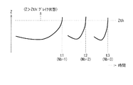
- FIG. 3 schematically shows an example of the break state and the number of breaks during ablation in a timing diagram.
- FIG. 3 an example of a measurement waveform of the impedance value Z between the electrode needle 1 (the electrode portion 11) and the return electrode plate 4 is shown along the time axis.
- the threshold value Zth of the impedance value Z shown in FIG. 3 corresponds to a specific example of the “first threshold value” in the present invention.
- the impedance value Z rapidly increases due to evaporation of water in the tissue in the affected area 90.
- Such a rapid rise (impedance rise) of the impedance value Z serves as an index of thermal coagulation of the tissue in the affected area 90, and thus serves as an indication of the stop timing at the time of ablation.
- a state in which the impedance value Z exceeds a predetermined threshold Zth (Z> Zth) is called a "break state" (see FIG. 3).
- ablation supply of power Pout
- ablation supply of power Pout
- the impedance value Z decreases again (see FIG. 3).
- the treatment to the affected part 90 is made by repeating such intermittent ablation several times.
- a predetermined time set in advance for example, about 10 seconds to about 15 seconds
- the ablation state is temporarily stopped three times at timings t1, t2, and t3 as time passes.
- the count of the number of breaks Nb may become inaccurate due to, for example, oversight of the break state. There is also the risk that it will cost extra.
- the transition to the second and subsequent break states is generally performed in a short time (see FIG. 3), it can be said that such a risk is very high.
- the number of breaks Nb may be increased more than necessary (for example, four times or more) within the ablation time. From these things, in the said comparative examples 1 and 2, as a result of the break part being given more than necessary to the affected part 90 at the time of the treatment by ablation, the pain which the patient 9 feels becomes large. The burden on the patient 9 may also be increased.
- this pain means the pain felt by the patient 9 at the time of treatment, and it is said that, for example, the right shoulder etc. often ache as a related pain through the spinal nerve.
- the impedance value Z rapidly rises, and therefore, when the power Pout is output, for example, as the constant power, the output voltage also rises rapidly.
- the temperature at the affected area 90 also tends to rise. Therefore, it is said that this pain has both electrical and thermal factors.
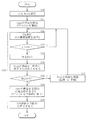
- FIG. 4 is a flowchart showing an example of ablation processing in the ablation system 5 of the present embodiment.
- the above-described threshold Zth (the threshold of the impedance value Z) and the threshold Nth (the threshold of the number of breaks Nb) described later are set (step S10 in FIG. 4).
- the set values of the threshold value Zth and the threshold value Nth are respectively input from the input unit 31 according to the operation by the operator of the power supply device 3 and supplied to the control unit 33.
- the threshold Nth corresponds to a specific example of the “second threshold” in the present invention.
- a method of defining the relative value a method of defining the impedance value Z at the start of ablation as a reference and a method of defining the minimum value of the impedance value Z after the initiation of ablation as the reference can be mentioned. Note that, as described above, such set values of the threshold Zth and the threshold Nth are not input according to the operation by the operator, but are set in advance in the power supply device 3, for example, when the product is shipped. It may be made to be.
- the power Pout is supplied from the power supply device 3 (power supply unit 32) between the electrode needle 1 and the return electrode plate 4 to start ablation of the affected part 90 (step S11).
- the start of the ablation is performed by the operation signal Sm being input from the input unit 31 and being supplied to the control unit 33 according to the operation by the operator of the power supply device 3. That is, in this example, ablation is manually initiated.
- the power supply unit 32 first measures the impedance value Z between the electrode needle 1 and the return electrode 4 (step S12). In other words, the control unit 33 acquires such measurement information of the impedance value Z. Then, when the impedance value Z measured in this manner is supplied from the power supply unit 32 to the control unit 33, the control unit 33 next performs the following determination. That is, control unit 33 determines whether this impedance value Z is larger than threshold value Zth set in step S10 (whether Z> Zth is satisfied) (step S13).
- step S13: N if it is determined that the impedance value Z is less than or equal to the threshold value Zth (Z> Zth is not satisfied) (step S13: N), the process returns to step S12 described above, and measurement of the impedance value Z is again performed It will be.
- step S13: Y when it is determined that the impedance value Z is larger than the threshold Zth (Z> Zth is satisfied) (step S13: Y), it means that the above-described break state is reached. Therefore, in this case, next, the control unit 33 automatically counts the number of breaks (break number Nb) (step S14).
- the count value of the number of breaks Nb is stored, for example, in various storage media in the control unit 33 as needed.
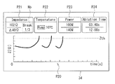
- the count value or the like of the break number Nb is displayed on the display unit 34 of the power supply 3 as needed, as schematically shown in FIG. 5, for example.
- the display unit 34 first, as schematically shown in FIG. 3 described above, the measured waveform of the impedance value Z is displayed along the time axis (symbols in FIG. 5) See P20).
- the current value (Impedance: refer to code P21) of the impedance value Z, the temperature information It (Temperature: refer to code P22) described above, and the output value of the power Pout (Power: code P23). Reference) and information on ablation time (Ablation Time: see code P24) are displayed respectively.
- the count value of the number of breaks Nb is displayed together with the current value (see the code P21) of the impedance value Z.
- control unit 33 temporarily stops the ablation by temporarily decreasing or stopping the supply of the power Pout from the power supply unit 32 using the control signal CTL1 described above (step S15).
- the impedance value Z is lowered again and the break state is left.
- control unit 33 determines whether the number of breaks Nb counted in step S14 is equal to or more than the threshold Nth set in step S10 (whether Nb Nb Nth is satisfied) (step S16). ). If it is determined that the number of breaks Nb is less than the threshold Nth (not satisfying Nb N Nth) (step S16: N), then the supply (ablation) of the power Pout is resumed automatically or manually. (Step S17).
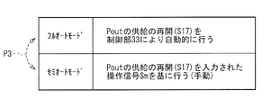
- FIG. 6 shows an example of the operation mode at the time of the supply resumption of the power Pout (step S17).
- the operation mode at this time there are, for example, two types of operation modes of "full auto mode” and "semi-auto mode".
- the full auto mode corresponds to one specific example of the "first operation mode” in the present invention
- the semi-auto mode corresponds to one specific example of the "second operation mode” in the present invention.
- step S16 when the number of breaks Nb has not reached the threshold Nth (step S16: N), the controller 33 automatically resumes the supply (ablation) of the power Pout (step S17). Specifically, control unit 33 automatically resumes the supply of power Pout from power supply unit 32 using control signal CTL1 described above. That is, in the full auto mode, the supply of the power Pout is automatically resumed.
- step S16 N
- the control unit 33 is selected based on the operation signal Sm input according to the operation by the operator of the power supply device 3.
- such two types of operation modes (“full auto mode” and “semi auto mode”) may be switchable (shown in FIG. 6). See dashed arrow P3). That is, for example, based on the operation signal Sm input according to the operation by the operator of the power supply device 3, these two types of operation modes may be switched as needed.
- the process returns to step S12 described above, and the measurement of the impedance value Z is performed again.
- the impedance value Z can be continuously measured even in the above-described break state.
- the supply of the power Pout is temporarily “stopped” in step S15, measurement of the impedance value Z is not performed in the break state.
- step S16: Y if it is determined in step S16 described above that the number of breaks Nb is equal to or greater than the threshold Nth (Nb N Nth is satisfied) (step S16: Y), the control unit 33 performs the following control Do. That is, when the number of breaks Nb reaches the threshold Nth (step S16: Y), the control unit 33 automatically stops (completely stops) the supply of the power Pout from the power supply unit 32, thereby automatically performing ablation. (Step S18). Specifically, the control unit 33 automatically stops the supply of the power Pout using the control signal CTL1 described above. Thereby, the ablation on the affected part 90 is automatically ended by the control unit 33.
- control unit 33 automatically stops the supply of the cooling liquid L from the liquid supply device 2 after automatically terminating the ablation (step S18) in this manner (step S19). . Specifically, the control unit 33 automatically stops the supply of the liquid L from the liquid supply unit 21 using the control signal CTL2 described above. Thereby, the circulation of the liquid L between the inside of the liquid supply device 2 and the inside of the electrode needle 1 is stopped (see FIG. 1), and the cooling operation (cooling) on the electrode needle 1 is stopped. This is the end of the series of processes shown in FIG. 4 (process example of ablation according to the present embodiment).
- the control unit 33 performs the following control at the time of ablation. That is, first, the control unit 33 measures the impedance value Z between the electrode needle 1 and the return electrode plate 4 (Step S12 in FIG. 4), and the number of break states where the impedance value Z exceeds the threshold Zth ( The number of breaks Nb) is counted (step S14). Then, when the number of breaks Nb reaches the threshold Nth, the control unit 33 automatically stops the supply of the power Pout to automatically terminate the ablation (step S18).
- the present embodiment it is as follows. That is, for example, as described above, when manually terminating ablation after confirming the number of breaks Nb visually (Comparative Example 1), or after a predetermined waiting time has elapsed without confirming the number of breaks Nb Effective ablation can be easily performed as compared with the case where ablation is automatically terminated (Comparative Example 2) or the like. Therefore, in the present embodiment, the convenience when using the ablation system 5 can be improved as compared with the comparative examples 1 and 2 and the like.
- the display unit 34 for displaying the count value of the number of breaks Nb is provided in the power supply device 3 (see FIG. 5). People will be able to grasp at any time. Thus, the convenience can be further improved.
- the control unit 33 automatically restarts (“full auto shown in FIG. In the case of executing “mode”, it becomes as follows. That is, in the "full mode", the supply of power Pout is also automatically resumed, so a series of processes from the start to the end of the ablation (each process of steps S12 to S19 in FIG. 4) Will be done automatically. Thus, the convenience can be further improved.
- these two types of operation modes can be switched (see arrow P3 in FIG. 6). become that way. That is, when the supply (ablation) of the power Pout is restarted (step S17 in FIG. 4), these two types of modes can be switched as needed according to, for example, the application, the situation, and the like. Thus, the convenience can be further improved.
- the control unit 33 automatically stops the supply of the liquid L after automatically terminating the ablation (step S18 in FIG. 4). Since it has been made to do (Step S19), it becomes as follows. That is, for example, the supply stop of the liquid L can be realized at an appropriate timing as compared with the case where the supply of the liquid L is manually stopped after the end of the ablation (Comparative Example 3). As a result, the possibility that the affected area 90 (tissue) after ablation is cooled more than necessary by the liquid L is avoided, and the ablation condition of the affected area 90 can be checked more accurately. Therefore, in the present embodiment, it is possible to further improve the convenience as compared with Comparative Example 3 described above.
- each member demonstrated in the said embodiment are not limited, It is good also as another material.
- the structure of the electrode needle 1 was mentioned concretely and demonstrated, it is not necessary to necessarily provide all the members and may further provide another member.
- the values and ranges of the various parameters described in the above embodiment, and the magnitude relationship are not limited to those described in the above embodiment, and other values, ranges, magnitude relationships, and the like may be used.
- the block configurations of the liquid supply device 2 and the power supply device 3 have been specifically described, but it is not necessary to include all the blocks described in the above embodiment. It may further comprise a block. Further, the ablation system 5 as a whole may further include other devices in addition to the devices described in the above embodiment.
- the control operation (a method of ablation) in the control unit 33 including the power supply control function and the liquid supply control function has been specifically described.
- the control method (ablation method) in the power supply control function and the liquid supply control function and the like is not limited to the method described in the above embodiment.
- the series of processes described in the above embodiment may be performed by hardware (circuit) or may be performed by software (program).
- the software is configured by a group of programs for causing a computer to execute each function.
- each program may be incorporated in advance in the computer and used, or may be installed and used in the computer from a network or a recording medium.
Landscapes
- Health & Medical Sciences (AREA)
- Surgery (AREA)
- Engineering & Computer Science (AREA)
- Life Sciences & Earth Sciences (AREA)
- Biomedical Technology (AREA)
- Otolaryngology (AREA)
- Nuclear Medicine, Radiotherapy & Molecular Imaging (AREA)
- Plasma & Fusion (AREA)
- Physics & Mathematics (AREA)
- Heart & Thoracic Surgery (AREA)
- Medical Informatics (AREA)
- Molecular Biology (AREA)
- Animal Behavior & Ethology (AREA)
- General Health & Medical Sciences (AREA)
- Public Health (AREA)
- Veterinary Medicine (AREA)
- Surgical Instruments (AREA)
Abstract
Description
1.実施の形態(電源装置内の制御部においてブレイク回数の自動カウント等を行う例)
2.変形例
[構成]
図1は、本発明の一実施の形態に係るアブレーションシステム(アブレーションシステム5)の全体構成例を、模式的にブロック図で表したものである。このアブレーションシステム5は、例えば図1に示したように、患者9の体内における患部90を治療する際に用いられるシステムであり、そのような患部90に対して所定のアブレーションを行うようになっている。なお、上記した患部90としては、例えば、癌(肝癌,肺癌,乳癌,腎臓癌,甲状腺癌など)等の腫瘍を有する患部が挙げられる。
電極針1は、例えば図1中の矢印P1で示したように、患者9の体内における患部90に対して、経皮的に穿刺される針である。この電極針1は、上記したアブレーションの際に使用されるものであり、例えば図1に示したように、電極部11および被覆部12を有している。なお、このような電極針1の内部には、後述する液体供給装置2から供給される液体Lが、循環して流れるようになっている(図1参照)。
液体供給装置2は、上記した電極針1に対して冷却用の液体Lを供給する装置であり、例えば図1に示したように、液体供給部21を有している。なお、この冷却用の液体Lとしては、例えば、滅菌水や、滅菌した生理食塩水などが挙げられる。
電源装置3は、電極針1と対極板4との間にアブレーションを行うための電力Pout(例えば高周波(RF;Radio Frequency)の電力)を供給すると共に、上記した液体供給装置2における液体Lの供給動作を制御する装置である。この電源装置3は、図1に示したように、入力部31、電源部32、制御部33および表示部34を有している。
対極板4は、例えば図1に示したように、アブレーションの際に患者9の体表に装着された状態で用いられるものである。詳細は後述するが、アブレーションの際に、前述した電極針1(電極部11)とこの対極板4との間で、高周波通電がなされる(電力Poutが供給される)ようになっている。また、詳細は後述するが、このようなアブレーションの際に、図1に示したように、電極針1(電極部11)と対極板4との間のインピーダンス値Zが随時測定され、測定されたインピーダンス値Zが、電源装置3内において電源部32から制御部33へと供給されるようになっている。
(A.基本動作)
このアブレーションシステム5では、例えば癌等の腫瘍を有する患部90を治療する際に、そのような患部90に対して所定のアブレーションが行われる(図1参照)。このようなアブレーションでは、まず、例えば図1中の矢印P1で示したように、患者9の体内の患部90に対し、電極針1が先端側(電極部11側)から経皮的に穿刺される。そして、この電極針1と対極板4との間に、電源装置3(電源部32)から電力Pout(例えば高周波電力)が供給されることで、患部90に対して、ジュール発熱によるアブレーションが行われる。
ここで、図1,図2に加えて図3を参照して、上記したアブレーションの詳細について説明する。図3は、アブレーションの際のブレイク状態およびブレイク回数の一例を、タイミング図にて模式的に表したものである。具体的には、この図3では、電極針1(電極部11)と対極板4との間のインピーダンス値Zの測定波形例を、時間軸に沿って示している。なお、図3中に示したインピーダンス値Zの閾値Zthは、本発明における「第1の閾値」の一具体例に対応している。
ところで、このようなアブレーションシステムによるアブレーションの際に、従来の一般的な手法では、以下のようにしてアブレーションを終了させるようになっている。具体的には、まず、ブレイク回数Nbを、電源装置3の操作者が目視等で確認してから(例えば上記したように、2~3回程度)、アブレーションを手動で終了させる手法(比較例1)が挙げられる。また、ブレイク回数Nbを確認せずに、所定の待機時間(固定値)が経過してから電力Poutの供給を自動的に停止することで、アブレーションを自動終了させる手法(比較例2)が挙げられる。
そこで、例えば図4に示したように、本実施の形態のアブレーションシステム5では、以下詳述する手法でアブレーションを行うことで、上記比較例1,2などにおける課題を解決するようにしている。この図4は、本実施の形態のアブレーションシステム5におけるアブレーションの処理例を、流れ図で表したものである。
このようにして、本実施の形態のアブレーションシステム5では、制御部33はアブレーションの際に、以下のような制御を行う。すなわち、まず、制御部33は、電極針1と対極板4との間のインピーダンス値Zを測定する(図4のステップS12)と共に、このインピーダンス値Zが閾値Zthを越えたブレイク状態の回数(ブレイク回数Nb)をカウントする(ステップS14)。そして、制御部33は、このブレイク回数Nbが閾値Nthに到達した場合には、電力Poutの供給を自動的に停止させることにより、アブレーションを自動的に終了させる(ステップS18)。
以上、実施の形態を挙げて本発明を説明したが、本発明はこの実施の形態に限定されず、種々の変形が可能である。
Claims (6)
- 体内の患部に対して経皮的に穿刺される電極針と、
前記電極針と対極板との間にアブレーションを行うための電力を供給する電源部と、前記電源部における前記電力の供給動作を制御する制御部と、を有する電源装置と
を備え、
前記制御部は、
前記アブレーションの際に、前記電極針と前記対極板との間のインピーダンス値を測定すると共に、前記インピーダンス値が第1閾値を越えたブレイク状態の回数であるブレイク回数をカウントし、
前記ブレイク回数が第2閾値に到達した場合には、前記電力の供給を自動的に停止させることにより、前記アブレーションを自動的に終了させる
アブレーションシステム。 - 前記電源装置は、前記ブレイク回数のカウント値を表示する表示部を更に有する
請求項1に記載のアブレーションシステム。 - 前記制御部は、
前記ブレイク状態となった場合には、前記ブレイク回数をカウントすると共に、前記電力の供給を一時的に低下または停止させ、
前記ブレイク回数が前記第2閾値に到達していない場合には、前記電力の供給を自動的に再開させる
請求項1または請求項2に記載のアブレーションシステム。 - 前記制御部は、
前記ブレイク状態となった場合には、前記ブレイク回数をカウントすると共に、前記電力の供給を一時的に低下または停止させ、
前記ブレイク回数が前記第2閾値に到達していない場合には、操作者による操作に応じて入力される操作信号に基づいて、前記電力の供給を再開させる
請求項1または請求項2に記載のアブレーションシステム。 - 前記電源装置では、第1の動作モードと第2の動作モードとが切り替え可能になっており、
前記第1の動作モードでは、前記制御部は、
前記ブレイク状態となった場合には、前記ブレイク回数をカウントすると共に、前記電力の供給を一時的に低下または停止させ、
前記ブレイク回数が前記第2閾値に到達していない場合には、前記電力の供給を自動的に再開させ、
前記第2の動作モードでは、前記制御部は、
前記ブレイク状態となった場合には、前記ブレイク回数をカウントすると共に、前記電力の供給を一時的に低下または停止させ、
前記ブレイク回数が前記第2閾値に到達していない場合には、操作者による操作に応じて入力される操作信号に基づいて、前記電力の供給を再開させる
請求項1または請求項2に記載のアブレーションシステム。 - 前記電極針に対して冷却用の液体を供給する液体供給装置を更に備え、
前記制御部は、前記ブレイク回数が前記第2閾値に到達した場合、前記アブレーションを自動的に終了させた後に、前記液体の供給も自動的に停止させる
請求項1ないし請求項5のいずれか1項に記載のアブレーションシステム。
Priority Applications (3)
| Application Number | Priority Date | Filing Date | Title |
|---|---|---|---|
| EP18851209.9A EP3656324B1 (en) | 2017-08-29 | 2018-02-19 | Ablation system |
| CN201880048176.0A CN110944590B (zh) | 2017-08-29 | 2018-02-19 | 消融系统 |
| KR1020207003535A KR102336199B1 (ko) | 2017-08-29 | 2018-02-19 | 어블레이션 시스템 |
Applications Claiming Priority (2)
| Application Number | Priority Date | Filing Date | Title |
|---|---|---|---|
| JP2017164461A JP6853145B2 (ja) | 2017-08-29 | 2017-08-29 | アブレーションシステム |
| JP2017-164461 | 2017-08-29 |
Publications (1)
| Publication Number | Publication Date |
|---|---|
| WO2019043991A1 true WO2019043991A1 (ja) | 2019-03-07 |
Family
ID=65525331
Family Applications (1)
| Application Number | Title | Priority Date | Filing Date |
|---|---|---|---|
| PCT/JP2018/005775 Ceased WO2019043991A1 (ja) | 2017-08-29 | 2018-02-19 | アブレーションシステム |
Country Status (6)
| Country | Link |
|---|---|
| EP (1) | EP3656324B1 (ja) |
| JP (1) | JP6853145B2 (ja) |
| KR (1) | KR102336199B1 (ja) |
| CN (1) | CN110944590B (ja) |
| TW (1) | TWI670041B (ja) |
| WO (1) | WO2019043991A1 (ja) |
Families Citing this family (5)
| Publication number | Priority date | Publication date | Assignee | Title |
|---|---|---|---|---|
| CN111529052B (zh) * | 2020-04-16 | 2021-05-07 | 上海睿刀医疗科技有限公司 | 一种预测电脉冲消融区域的系统 |
| WO2022038728A1 (ja) * | 2020-08-20 | 2022-02-24 | 日本ライフライン株式会社 | アブレーションシステム |
| WO2022091224A1 (ja) * | 2020-10-27 | 2022-05-05 | 日本ライフライン株式会社 | アブレーションシステム |
| WO2022091369A1 (ja) * | 2020-10-30 | 2022-05-05 | 日本ライフライン株式会社 | アブレーションシステム |
| SE2150579A1 (en) * | 2021-05-06 | 2022-11-07 | Curative Cancer Treat By Heat Cctbh Ab | Tumor denaturization control in curative cancer treatment |
Citations (4)
| Publication number | Priority date | Publication date | Assignee | Title |
|---|---|---|---|---|
| JP2002065690A (ja) * | 2000-08-23 | 2002-03-05 | Olympus Optical Co Ltd | 電気手術装置 |
| JP2004008581A (ja) * | 2002-06-07 | 2004-01-15 | Aloka Co Ltd | 電気手術装置 |
| JP2008514271A (ja) * | 2004-09-27 | 2008-05-08 | ビブラテック・アクチボラゲット | 腫瘍の治療のための機構 |
| JP2008114042A (ja) * | 2006-10-31 | 2008-05-22 | Olympus Medical Systems Corp | 高周波手術装置及び高周波手術方法 |
Family Cites Families (6)
| Publication number | Priority date | Publication date | Assignee | Title |
|---|---|---|---|---|
| JP5641591B1 (ja) * | 2013-06-27 | 2014-12-17 | 日本ライフライン株式会社 | カテーテルシステム |
| JP2015008830A (ja) * | 2013-06-27 | 2015-01-19 | 日本ライフライン株式会社 | カテーテルシステム |
| US10342606B2 (en) * | 2014-05-06 | 2019-07-09 | Cosman Instruments, Llc | Electrosurgical generator |
| CN107427280B (zh) * | 2015-02-27 | 2021-05-11 | 皇家飞利浦有限公司 | 用于基于弹性成像监测的自适应消融和治疗的系统和方法 |
| US10285751B2 (en) * | 2015-10-16 | 2019-05-14 | Biosense Webster (Israel) Ltd. | System and method for controlling catheter power based on renal ablation response |
| CN105496549A (zh) * | 2015-10-29 | 2016-04-20 | 绵阳立德电子股份有限公司 | 一种射频发生器及利用该射频器产生射频能量的方法 |
-
2017
- 2017-08-29 JP JP2017164461A patent/JP6853145B2/ja active Active
-
2018
- 2018-02-19 WO PCT/JP2018/005775 patent/WO2019043991A1/ja not_active Ceased
- 2018-02-19 CN CN201880048176.0A patent/CN110944590B/zh active Active
- 2018-02-19 EP EP18851209.9A patent/EP3656324B1/en active Active
- 2018-02-19 KR KR1020207003535A patent/KR102336199B1/ko active Active
- 2018-04-26 TW TW107114159A patent/TWI670041B/zh not_active IP Right Cessation
Patent Citations (4)
| Publication number | Priority date | Publication date | Assignee | Title |
|---|---|---|---|---|
| JP2002065690A (ja) * | 2000-08-23 | 2002-03-05 | Olympus Optical Co Ltd | 電気手術装置 |
| JP2004008581A (ja) * | 2002-06-07 | 2004-01-15 | Aloka Co Ltd | 電気手術装置 |
| JP2008514271A (ja) * | 2004-09-27 | 2008-05-08 | ビブラテック・アクチボラゲット | 腫瘍の治療のための機構 |
| JP2008114042A (ja) * | 2006-10-31 | 2008-05-22 | Olympus Medical Systems Corp | 高周波手術装置及び高周波手術方法 |
Non-Patent Citations (1)
| Title |
|---|
| See also references of EP3656324A4 * |
Also Published As
| Publication number | Publication date |
|---|---|
| KR102336199B1 (ko) | 2021-12-07 |
| JP2019041782A (ja) | 2019-03-22 |
| TW201912124A (zh) | 2019-04-01 |
| KR20200024924A (ko) | 2020-03-09 |
| CN110944590B (zh) | 2023-01-31 |
| EP3656324B1 (en) | 2026-01-21 |
| EP3656324A1 (en) | 2020-05-27 |
| CN110944590A (zh) | 2020-03-31 |
| TWI670041B (zh) | 2019-09-01 |
| EP3656324A4 (en) | 2021-04-07 |
| JP6853145B2 (ja) | 2021-03-31 |
Similar Documents
| Publication | Publication Date | Title |
|---|---|---|
| WO2019043991A1 (ja) | アブレーションシステム | |
| EP4082461B1 (en) | Apparatus for controlling output of radio frequency ablation power, and radio frequency ablation system | |
| JP2021120003A (ja) | エラストグラフィ監視に基づく適応的なアブレーション及び治療のシステム及び方法 | |
| EP3451964B1 (en) | Systems facilitating application of an appropriate thermal dosage in microwave ablation procedures | |
| WO2020262279A1 (ja) | 高周波処置装置および高周波処置方法 | |
| AU2025223867A1 (en) | System and method for an improved graphical user interface that provides independent control of multiple radiofrequency probes during an ablation procedure | |
| KR101737253B1 (ko) | 카테터 시스템 | |
| JP2015119895A (ja) | 熱伝導率測定システム | |
| JP7454682B2 (ja) | アブレーションシステム | |
| JP7455494B2 (ja) | アブレーションシステム | |
| WO2022091369A1 (ja) | アブレーションシステム | |
| JP7352011B2 (ja) | アブレーション制御システム | |
| TWI693918B (zh) | 消融裝置 | |
| JP6871194B2 (ja) | アブレーションデバイス | |
| JP7636365B2 (ja) | 電源装置、電気医療デバイスシステムおよび給電方法 | |
| US20250318875A1 (en) | Laser ablation method, apparatus and device, and computer readable storage medium | |
| TWI702028B (zh) | 消融裝置 | |
| WO2020174651A1 (ja) | カテーテルシステム | |
| WO2020174650A1 (ja) | カテーテルシステム |
Legal Events
| Date | Code | Title | Description |
|---|---|---|---|
| 121 | Ep: the epo has been informed by wipo that ep was designated in this application |
Ref document number: 18851209 Country of ref document: EP Kind code of ref document: A1 |
|
| ENP | Entry into the national phase |
Ref document number: 20207003535 Country of ref document: KR Kind code of ref document: A |
|
| ENP | Entry into the national phase |
Ref document number: 2018851209 Country of ref document: EP Effective date: 20200219 |
|
| NENP | Non-entry into the national phase |
Ref country code: DE |
|
| WWG | Wipo information: grant in national office |
Ref document number: 2018851209 Country of ref document: EP |