WO2019044971A1 - 浸炭用鋼板、及び、浸炭用鋼板の製造方法 - Google Patents
浸炭用鋼板、及び、浸炭用鋼板の製造方法 Download PDFInfo
- Publication number
- WO2019044971A1 WO2019044971A1 PCT/JP2018/032112 JP2018032112W WO2019044971A1 WO 2019044971 A1 WO2019044971 A1 WO 2019044971A1 JP 2018032112 W JP2018032112 W JP 2018032112W WO 2019044971 A1 WO2019044971 A1 WO 2019044971A1
- Authority
- WO
- WIPO (PCT)
- Prior art keywords
- less
- carbides
- carburizing
- steel sheet
- annealing
- Prior art date
- Legal status (The legal status is an assumption and is not a legal conclusion. Google has not performed a legal analysis and makes no representation as to the accuracy of the status listed.)
- Ceased
Links
Classifications
-
- C—CHEMISTRY; METALLURGY
- C21—METALLURGY OF IRON
- C21D—MODIFYING THE PHYSICAL STRUCTURE OF FERROUS METALS; GENERAL DEVICES FOR HEAT TREATMENT OF FERROUS OR NON-FERROUS METALS OR ALLOYS; MAKING METAL MALLEABLE, e.g. BY DECARBURISATION OR TEMPERING
- C21D1/00—General methods or devices for heat treatment, e.g. annealing, hardening, quenching or tempering
- C21D1/26—Methods of annealing
- C21D1/32—Soft annealing, e.g. spheroidising
-
- C—CHEMISTRY; METALLURGY
- C21—METALLURGY OF IRON
- C21D—MODIFYING THE PHYSICAL STRUCTURE OF FERROUS METALS; GENERAL DEVICES FOR HEAT TREATMENT OF FERROUS OR NON-FERROUS METALS OR ALLOYS; MAKING METAL MALLEABLE, e.g. BY DECARBURISATION OR TEMPERING
- C21D1/00—General methods or devices for heat treatment, e.g. annealing, hardening, quenching or tempering
- C21D1/74—Methods of treatment in inert gas, controlled atmosphere, vacuum or pulverulent material
- C21D1/76—Adjusting the composition of the atmosphere
-
- C—CHEMISTRY; METALLURGY
- C21—METALLURGY OF IRON
- C21D—MODIFYING THE PHYSICAL STRUCTURE OF FERROUS METALS; GENERAL DEVICES FOR HEAT TREATMENT OF FERROUS OR NON-FERROUS METALS OR ALLOYS; MAKING METAL MALLEABLE, e.g. BY DECARBURISATION OR TEMPERING
- C21D6/00—Heat treatment of ferrous alloys
- C21D6/004—Heat treatment of ferrous alloys containing Cr and Ni
-
- C—CHEMISTRY; METALLURGY
- C21—METALLURGY OF IRON
- C21D—MODIFYING THE PHYSICAL STRUCTURE OF FERROUS METALS; GENERAL DEVICES FOR HEAT TREATMENT OF FERROUS OR NON-FERROUS METALS OR ALLOYS; MAKING METAL MALLEABLE, e.g. BY DECARBURISATION OR TEMPERING
- C21D6/00—Heat treatment of ferrous alloys
- C21D6/005—Heat treatment of ferrous alloys containing Mn
-
- C—CHEMISTRY; METALLURGY
- C21—METALLURGY OF IRON
- C21D—MODIFYING THE PHYSICAL STRUCTURE OF FERROUS METALS; GENERAL DEVICES FOR HEAT TREATMENT OF FERROUS OR NON-FERROUS METALS OR ALLOYS; MAKING METAL MALLEABLE, e.g. BY DECARBURISATION OR TEMPERING
- C21D6/00—Heat treatment of ferrous alloys
- C21D6/007—Heat treatment of ferrous alloys containing Co
-
- C—CHEMISTRY; METALLURGY
- C21—METALLURGY OF IRON
- C21D—MODIFYING THE PHYSICAL STRUCTURE OF FERROUS METALS; GENERAL DEVICES FOR HEAT TREATMENT OF FERROUS OR NON-FERROUS METALS OR ALLOYS; MAKING METAL MALLEABLE, e.g. BY DECARBURISATION OR TEMPERING
- C21D6/00—Heat treatment of ferrous alloys
- C21D6/008—Heat treatment of ferrous alloys containing Si
-
- C—CHEMISTRY; METALLURGY
- C21—METALLURGY OF IRON
- C21D—MODIFYING THE PHYSICAL STRUCTURE OF FERROUS METALS; GENERAL DEVICES FOR HEAT TREATMENT OF FERROUS OR NON-FERROUS METALS OR ALLOYS; MAKING METAL MALLEABLE, e.g. BY DECARBURISATION OR TEMPERING
- C21D8/00—Modifying the physical properties of ferrous metals or ferrous alloys by deformation combined with, or followed by, heat treatment
- C21D8/02—Modifying the physical properties of ferrous metals or ferrous alloys by deformation combined with, or followed by, heat treatment during manufacturing of plates or strips
-
- C—CHEMISTRY; METALLURGY
- C21—METALLURGY OF IRON
- C21D—MODIFYING THE PHYSICAL STRUCTURE OF FERROUS METALS; GENERAL DEVICES FOR HEAT TREATMENT OF FERROUS OR NON-FERROUS METALS OR ALLOYS; MAKING METAL MALLEABLE, e.g. BY DECARBURISATION OR TEMPERING
- C21D8/00—Modifying the physical properties of ferrous metals or ferrous alloys by deformation combined with, or followed by, heat treatment
- C21D8/02—Modifying the physical properties of ferrous metals or ferrous alloys by deformation combined with, or followed by, heat treatment during manufacturing of plates or strips
- C21D8/0221—Modifying the physical properties of ferrous metals or ferrous alloys by deformation combined with, or followed by, heat treatment during manufacturing of plates or strips characterised by the working steps
- C21D8/0226—Hot rolling
-
- C—CHEMISTRY; METALLURGY
- C21—METALLURGY OF IRON
- C21D—MODIFYING THE PHYSICAL STRUCTURE OF FERROUS METALS; GENERAL DEVICES FOR HEAT TREATMENT OF FERROUS OR NON-FERROUS METALS OR ALLOYS; MAKING METAL MALLEABLE, e.g. BY DECARBURISATION OR TEMPERING
- C21D8/00—Modifying the physical properties of ferrous metals or ferrous alloys by deformation combined with, or followed by, heat treatment
- C21D8/02—Modifying the physical properties of ferrous metals or ferrous alloys by deformation combined with, or followed by, heat treatment during manufacturing of plates or strips
- C21D8/0221—Modifying the physical properties of ferrous metals or ferrous alloys by deformation combined with, or followed by, heat treatment during manufacturing of plates or strips characterised by the working steps
- C21D8/0236—Cold rolling
-
- C—CHEMISTRY; METALLURGY
- C21—METALLURGY OF IRON
- C21D—MODIFYING THE PHYSICAL STRUCTURE OF FERROUS METALS; GENERAL DEVICES FOR HEAT TREATMENT OF FERROUS OR NON-FERROUS METALS OR ALLOYS; MAKING METAL MALLEABLE, e.g. BY DECARBURISATION OR TEMPERING
- C21D8/00—Modifying the physical properties of ferrous metals or ferrous alloys by deformation combined with, or followed by, heat treatment
- C21D8/02—Modifying the physical properties of ferrous metals or ferrous alloys by deformation combined with, or followed by, heat treatment during manufacturing of plates or strips
- C21D8/0247—Modifying the physical properties of ferrous metals or ferrous alloys by deformation combined with, or followed by, heat treatment during manufacturing of plates or strips characterised by the heat treatment
- C21D8/0263—Modifying the physical properties of ferrous metals or ferrous alloys by deformation combined with, or followed by, heat treatment during manufacturing of plates or strips characterised by the heat treatment following hot rolling
-
- C—CHEMISTRY; METALLURGY
- C21—METALLURGY OF IRON
- C21D—MODIFYING THE PHYSICAL STRUCTURE OF FERROUS METALS; GENERAL DEVICES FOR HEAT TREATMENT OF FERROUS OR NON-FERROUS METALS OR ALLOYS; MAKING METAL MALLEABLE, e.g. BY DECARBURISATION OR TEMPERING
- C21D9/00—Heat treatment, e.g. annealing, hardening, quenching or tempering, adapted for particular articles; Furnaces therefor
- C21D9/46—Heat treatment, e.g. annealing, hardening, quenching or tempering, adapted for particular articles; Furnaces therefor for sheet metals
-
- C—CHEMISTRY; METALLURGY
- C22—METALLURGY; FERROUS OR NON-FERROUS ALLOYS; TREATMENT OF ALLOYS OR NON-FERROUS METALS
- C22C—ALLOYS
- C22C38/00—Ferrous alloys, e.g. steel alloys
- C22C38/001—Ferrous alloys, e.g. steel alloys containing N
-
- C—CHEMISTRY; METALLURGY
- C22—METALLURGY; FERROUS OR NON-FERROUS ALLOYS; TREATMENT OF ALLOYS OR NON-FERROUS METALS
- C22C—ALLOYS
- C22C38/00—Ferrous alloys, e.g. steel alloys
- C22C38/002—Ferrous alloys, e.g. steel alloys containing In, Mg, or other elements not provided for in one single group C22C38/001 - C22C38/60
-
- C—CHEMISTRY; METALLURGY
- C22—METALLURGY; FERROUS OR NON-FERROUS ALLOYS; TREATMENT OF ALLOYS OR NON-FERROUS METALS
- C22C—ALLOYS
- C22C38/00—Ferrous alloys, e.g. steel alloys
- C22C38/005—Ferrous alloys, e.g. steel alloys containing rare earths, i.e. Sc, Y, Lanthanides
-
- C—CHEMISTRY; METALLURGY
- C22—METALLURGY; FERROUS OR NON-FERROUS ALLOYS; TREATMENT OF ALLOYS OR NON-FERROUS METALS
- C22C—ALLOYS
- C22C38/00—Ferrous alloys, e.g. steel alloys
- C22C38/008—Ferrous alloys, e.g. steel alloys containing tin
-
- C—CHEMISTRY; METALLURGY
- C22—METALLURGY; FERROUS OR NON-FERROUS ALLOYS; TREATMENT OF ALLOYS OR NON-FERROUS METALS
- C22C—ALLOYS
- C22C38/00—Ferrous alloys, e.g. steel alloys
- C22C38/02—Ferrous alloys, e.g. steel alloys containing silicon
-
- C—CHEMISTRY; METALLURGY
- C22—METALLURGY; FERROUS OR NON-FERROUS ALLOYS; TREATMENT OF ALLOYS OR NON-FERROUS METALS
- C22C—ALLOYS
- C22C38/00—Ferrous alloys, e.g. steel alloys
- C22C38/04—Ferrous alloys, e.g. steel alloys containing manganese
-
- C—CHEMISTRY; METALLURGY
- C22—METALLURGY; FERROUS OR NON-FERROUS ALLOYS; TREATMENT OF ALLOYS OR NON-FERROUS METALS
- C22C—ALLOYS
- C22C38/00—Ferrous alloys, e.g. steel alloys
- C22C38/06—Ferrous alloys, e.g. steel alloys containing aluminium
-
- C—CHEMISTRY; METALLURGY
- C22—METALLURGY; FERROUS OR NON-FERROUS ALLOYS; TREATMENT OF ALLOYS OR NON-FERROUS METALS
- C22C—ALLOYS
- C22C38/00—Ferrous alloys, e.g. steel alloys
- C22C38/08—Ferrous alloys, e.g. steel alloys containing nickel
-
- C—CHEMISTRY; METALLURGY
- C22—METALLURGY; FERROUS OR NON-FERROUS ALLOYS; TREATMENT OF ALLOYS OR NON-FERROUS METALS
- C22C—ALLOYS
- C22C38/00—Ferrous alloys, e.g. steel alloys
- C22C38/12—Ferrous alloys, e.g. steel alloys containing tungsten, tantalum, molybdenum, vanadium, or niobium
-
- C—CHEMISTRY; METALLURGY
- C22—METALLURGY; FERROUS OR NON-FERROUS ALLOYS; TREATMENT OF ALLOYS OR NON-FERROUS METALS
- C22C—ALLOYS
- C22C38/00—Ferrous alloys, e.g. steel alloys
- C22C38/14—Ferrous alloys, e.g. steel alloys containing titanium or zirconium
-
- C—CHEMISTRY; METALLURGY
- C22—METALLURGY; FERROUS OR NON-FERROUS ALLOYS; TREATMENT OF ALLOYS OR NON-FERROUS METALS
- C22C—ALLOYS
- C22C38/00—Ferrous alloys, e.g. steel alloys
- C22C38/18—Ferrous alloys, e.g. steel alloys containing chromium
- C22C38/32—Ferrous alloys, e.g. steel alloys containing chromium with boron
-
- C—CHEMISTRY; METALLURGY
- C22—METALLURGY; FERROUS OR NON-FERROUS ALLOYS; TREATMENT OF ALLOYS OR NON-FERROUS METALS
- C22C—ALLOYS
- C22C38/00—Ferrous alloys, e.g. steel alloys
- C22C38/18—Ferrous alloys, e.g. steel alloys containing chromium
- C22C38/38—Ferrous alloys, e.g. steel alloys containing chromium with more than 1.5% by weight of manganese
-
- C—CHEMISTRY; METALLURGY
- C22—METALLURGY; FERROUS OR NON-FERROUS ALLOYS; TREATMENT OF ALLOYS OR NON-FERROUS METALS
- C22C—ALLOYS
- C22C38/00—Ferrous alloys, e.g. steel alloys
- C22C38/18—Ferrous alloys, e.g. steel alloys containing chromium
- C22C38/40—Ferrous alloys, e.g. steel alloys containing chromium with nickel
- C22C38/42—Ferrous alloys, e.g. steel alloys containing chromium with nickel with copper
-
- C—CHEMISTRY; METALLURGY
- C22—METALLURGY; FERROUS OR NON-FERROUS ALLOYS; TREATMENT OF ALLOYS OR NON-FERROUS METALS
- C22C—ALLOYS
- C22C38/00—Ferrous alloys, e.g. steel alloys
- C22C38/18—Ferrous alloys, e.g. steel alloys containing chromium
- C22C38/40—Ferrous alloys, e.g. steel alloys containing chromium with nickel
- C22C38/44—Ferrous alloys, e.g. steel alloys containing chromium with nickel with molybdenum or tungsten
-
- C—CHEMISTRY; METALLURGY
- C22—METALLURGY; FERROUS OR NON-FERROUS ALLOYS; TREATMENT OF ALLOYS OR NON-FERROUS METALS
- C22C—ALLOYS
- C22C38/00—Ferrous alloys, e.g. steel alloys
- C22C38/18—Ferrous alloys, e.g. steel alloys containing chromium
- C22C38/40—Ferrous alloys, e.g. steel alloys containing chromium with nickel
- C22C38/46—Ferrous alloys, e.g. steel alloys containing chromium with nickel with vanadium
-
- C—CHEMISTRY; METALLURGY
- C22—METALLURGY; FERROUS OR NON-FERROUS ALLOYS; TREATMENT OF ALLOYS OR NON-FERROUS METALS
- C22C—ALLOYS
- C22C38/00—Ferrous alloys, e.g. steel alloys
- C22C38/18—Ferrous alloys, e.g. steel alloys containing chromium
- C22C38/40—Ferrous alloys, e.g. steel alloys containing chromium with nickel
- C22C38/48—Ferrous alloys, e.g. steel alloys containing chromium with nickel with niobium or tantalum
-
- C—CHEMISTRY; METALLURGY
- C22—METALLURGY; FERROUS OR NON-FERROUS ALLOYS; TREATMENT OF ALLOYS OR NON-FERROUS METALS
- C22C—ALLOYS
- C22C38/00—Ferrous alloys, e.g. steel alloys
- C22C38/18—Ferrous alloys, e.g. steel alloys containing chromium
- C22C38/40—Ferrous alloys, e.g. steel alloys containing chromium with nickel
- C22C38/50—Ferrous alloys, e.g. steel alloys containing chromium with nickel with titanium or zirconium
-
- C—CHEMISTRY; METALLURGY
- C22—METALLURGY; FERROUS OR NON-FERROUS ALLOYS; TREATMENT OF ALLOYS OR NON-FERROUS METALS
- C22C—ALLOYS
- C22C38/00—Ferrous alloys, e.g. steel alloys
- C22C38/18—Ferrous alloys, e.g. steel alloys containing chromium
- C22C38/40—Ferrous alloys, e.g. steel alloys containing chromium with nickel
- C22C38/52—Ferrous alloys, e.g. steel alloys containing chromium with nickel with cobalt
-
- C—CHEMISTRY; METALLURGY
- C22—METALLURGY; FERROUS OR NON-FERROUS ALLOYS; TREATMENT OF ALLOYS OR NON-FERROUS METALS
- C22C—ALLOYS
- C22C38/00—Ferrous alloys, e.g. steel alloys
- C22C38/18—Ferrous alloys, e.g. steel alloys containing chromium
- C22C38/40—Ferrous alloys, e.g. steel alloys containing chromium with nickel
- C22C38/54—Ferrous alloys, e.g. steel alloys containing chromium with nickel with boron
-
- C—CHEMISTRY; METALLURGY
- C22—METALLURGY; FERROUS OR NON-FERROUS ALLOYS; TREATMENT OF ALLOYS OR NON-FERROUS METALS
- C22C—ALLOYS
- C22C38/00—Ferrous alloys, e.g. steel alloys
- C22C38/18—Ferrous alloys, e.g. steel alloys containing chromium
- C22C38/40—Ferrous alloys, e.g. steel alloys containing chromium with nickel
- C22C38/58—Ferrous alloys, e.g. steel alloys containing chromium with nickel with more than 1.5% by weight of manganese
-
- C—CHEMISTRY; METALLURGY
- C22—METALLURGY; FERROUS OR NON-FERROUS ALLOYS; TREATMENT OF ALLOYS OR NON-FERROUS METALS
- C22C—ALLOYS
- C22C38/00—Ferrous alloys, e.g. steel alloys
- C22C38/60—Ferrous alloys, e.g. steel alloys containing lead, selenium, tellurium, or antimony, or more than 0.04% by weight of sulfur
-
- C—CHEMISTRY; METALLURGY
- C23—COATING METALLIC MATERIAL; COATING MATERIAL WITH METALLIC MATERIAL; CHEMICAL SURFACE TREATMENT; DIFFUSION TREATMENT OF METALLIC MATERIAL; COATING BY VACUUM EVAPORATION, BY SPUTTERING, BY ION IMPLANTATION OR BY CHEMICAL VAPOUR DEPOSITION, IN GENERAL; INHIBITING CORROSION OF METALLIC MATERIAL OR INCRUSTATION IN GENERAL
- C23C—COATING METALLIC MATERIAL; COATING MATERIAL WITH METALLIC MATERIAL; SURFACE TREATMENT OF METALLIC MATERIAL BY DIFFUSION INTO THE SURFACE, BY CHEMICAL CONVERSION OR SUBSTITUTION; COATING BY VACUUM EVAPORATION, BY SPUTTERING, BY ION IMPLANTATION OR BY CHEMICAL VAPOUR DEPOSITION, IN GENERAL
- C23C8/00—Solid state diffusion of only non-metal elements into metallic material surfaces; Chemical surface treatment of metallic material by reaction of the surface with a reactive gas, leaving reaction products of surface material in the coating, e.g. conversion coatings, passivation of metals
- C23C8/06—Solid state diffusion of only non-metal elements into metallic material surfaces; Chemical surface treatment of metallic material by reaction of the surface with a reactive gas, leaving reaction products of surface material in the coating, e.g. conversion coatings, passivation of metals using gases
- C23C8/08—Solid state diffusion of only non-metal elements into metallic material surfaces; Chemical surface treatment of metallic material by reaction of the surface with a reactive gas, leaving reaction products of surface material in the coating, e.g. conversion coatings, passivation of metals using gases only one element being applied
- C23C8/20—Carburising
- C23C8/22—Carburising of ferrous surfaces
-
- C—CHEMISTRY; METALLURGY
- C21—METALLURGY OF IRON
- C21D—MODIFYING THE PHYSICAL STRUCTURE OF FERROUS METALS; GENERAL DEVICES FOR HEAT TREATMENT OF FERROUS OR NON-FERROUS METALS OR ALLOYS; MAKING METAL MALLEABLE, e.g. BY DECARBURISATION OR TEMPERING
- C21D1/00—General methods or devices for heat treatment, e.g. annealing, hardening, quenching or tempering
- C21D1/06—Surface hardening
-
- C—CHEMISTRY; METALLURGY
- C21—METALLURGY OF IRON
- C21D—MODIFYING THE PHYSICAL STRUCTURE OF FERROUS METALS; GENERAL DEVICES FOR HEAT TREATMENT OF FERROUS OR NON-FERROUS METALS OR ALLOYS; MAKING METAL MALLEABLE, e.g. BY DECARBURISATION OR TEMPERING
- C21D2211/00—Microstructure comprising significant phases
- C21D2211/005—Ferrite
Definitions
- the present invention relates to a steel plate for carburizing and a method of manufacturing a steel plate for carburizing.
- Patent Document 1 a technique is proposed in which the structure of a hot-rolled steel sheet is composed of ferrite and pearlite, and then spheroidizing annealing is performed to spheroidize the carbide.
- Patent Document 2 after controlling the grain size of carbides, the ratio of the number of carbides in ferrite grain boundaries to the number of carbides in ferrite grains is controlled, and further, the crystal grains of ferrite as a matrix phase There has been proposed a technique for improving the impact characteristics of a member after carburizing by controlling the diameter.
- the cold workability is controlled by further controlling the aspect ratio of the ferrite after controlling the grain size and aspect ratio of the carbide and the crystal grain size of the ferrite which is the matrix. Techniques to improve have been proposed.
- Patent No. 3094856 International Publication No. 2016/190370 International Publication No. 2016/148037
- the mechanical structure parts as described above are required to be hardenable in order to increase the strength. That is, in order to form a member having a complicated shape by cold working, it is required to secure formability while maintaining hardenability.
- this invention is made in view of the said problem, and the place made into the objective of this invention is providing the steel plate for carburizing excellent in ductility, and its manufacturing method.
- the present inventors diligently studied about the method of solving the above-mentioned subject. As a result, as described in detail below, ductility is maintained while maintaining hardenability by reducing the number density of carbides generated in the steel plate and refining the ferrite crystal grains in the steel plate. With the idea that it is possible to realize an excellent carburizing steel sheet, the present invention has been completed.
- the gist of the present invention completed based on this idea is as follows.
- the temperature range from the temperature at the end of hot finish rolling to the cooling stop temperature is 50 ° C./s or more and 250 ° C./s or less Steel sheet obtained by the hot rolling process which is cooled at a temperature of 700 ° C.
- the first annealing step of heating to a temperature range holds 1h or 100h less in a temperature range below the Ac 1 point
- the second annealing step of maintaining the temperature within the temperature range of 1 to 790 ° C. and 1 h to 100 h inclusive, and the steel sheet after annealing in the second annealing step at the end of the annealing in the second annealing step A cooling step of performing cooling to set an average cooling rate in a temperature range from a temperature of 5 ° C. to a temperature of 550 ° C. to 1 ° C./h to 100 ° C./h. [5] Between the hot rolling step and the first annealing step, the steel plate obtained in the hot rolling step is held in the air at a temperature of 40 ° C. to 70 ° C. for 72 h to 350 h or less.
- [X] represents content (unit: mass%) of the element X, and when not containing an applicable element, suppose that zero is substituted.
- Ductility is a characteristic composed of uniform elongation and local elongation.
- various techniques for mainly improving the uniform elongation have been proposed.
- the present invention is characterized in that two-step annealing is performed when manufacturing the steel sheet for carburizing according to the present invention as described below.
- two-step annealing is performed when manufacturing the steel sheet for carburizing according to the present invention as described below.
- coarse graining is promoted by performing two-step annealing, and deterioration of local elongation in ductility can not be avoided.
- the inventors of the present invention have the idea that it is possible to suppress the occurrence of voids because the total area of the interface between ferrite and carbide is reduced by reducing the number density of carbides present in the steel sheet. It came to get.
- the present inventors have found that, in the spheroidizing annealing step, the steel sheet after the hot rolling process, heating to a temperature below zone 1 point Ac, 1h or 100h less in a temperature range of below according Ac 1 point annealed in the first stage to hold, then holding the steel sheet after the annealing in the first stage, heated to Ac 1 point than 790 ° C. or less, 1h or 100h following according Ac 1 point than 790 ° C. below the temperature range It succeeded in reducing the number density of carbides by giving the second step annealing.
- the first stage heat holding is carried out at Ac 1 point or less, thereby promoting the diffusion of carbon to spheroidize the plate-like carbide formed in the hot rolling process.
- the steel sheet structure is mainly composed of ferrite and carbides, and fine carbides and coarse carbides are mixed in the steel sheet structure.
- the second stage of heating and holding is performed at an Ac 1 point or more to dissolve fine carbides and reduce the number density of carbides. In the temperature range above the Ac 1 point, it is considered that since the Oswald growth of carbide occurs, the dissolution of fine carbide can be promoted to reduce the number density of carbide.
- the inventors of the present invention came to the idea that when grain boundaries increase due to grain refinement, voids generated at the interface between carbide and ferrite become difficult to connect. As a result of intensive studies based on this idea, the present inventors have found that if the average grain size of ferrite is controlled to 10 ⁇ m or less, the effect of suppressing the connection of voids can be obtained.
- the austenite before transformation is made thin by using for hot-rolling a steel plate containing 0.010% or more of Ti. It can be granulated, and additionally, the steel sheet is cooled and wound at an average cooling rate of 50 ° C./s or more immediately after the hot finish rolling, thereby suppressing grain growth of austenite, and phase transformation to ferrite. I found that I could start it. As a result, nucleation sites of ferrite are increased, and ferrite particles can be miniaturized.
- both of the uniform elongation and the local elongation can be improved by the microstructural control from the two viewpoints, and as a result, while maintaining the hardenability, the steel plate for carburizing steel superior in ductility is obtained Succeeded. As a result of the steel sheet for carburizing steels being superior to ductility, more excellent formability is developed.
- the improvement of the ductility (uniform elongation and local elongation) mentioned above has the effect so that it is a steel plate with high hardenability.
- ductility is significantly improved. Therefore, it is possible to improve the ductility while maintaining the hardenability by the structure control as outlined above. As a result of the steel sheet for carburizing steels being superior to ductility, more excellent formability is developed.
- a carburizing steel plate and a method for manufacturing the same according to an embodiment of the present invention have been completed based on the above-described findings. Below, the steel plate for carburization concerning this embodiment completed based on this knowledge, and its manufacturing method are explained in detail.
- the steel plate for carburizing according to the present embodiment has a predetermined chemical component as described in detail below.
- the number of carbides per 1000 ⁇ m 2 is 100 or less, and the proportion of the number of carbides having an aspect ratio of 2.0 or less is 10% with respect to all carbides.
- This is a specific microstructure having a carbide equivalent circle diameter of 5.0 ⁇ m or less and an average grain size of ferrite of 10 ⁇ m or less.
- C is an element necessary to secure the strength of the central portion of the thickness of the finally obtained carburized member. Further, in the carburized steel sheet, C is an element which is dissolved in ferrite grain boundaries to increase the strength of the grain boundaries and contributes to the improvement of local elongation.
- the content of C is set to 0.02% or more.
- the content of C is preferably 0.05% or more.
- the content of C is less than 0.30%.
- the content of C is preferably 0.20% or less.
- the content of C is more preferably 0.10% or less, and still more preferably less than 0.10%. .
- Si silicon
- Si is an element which acts to deoxidize molten steel to make the steel sound.
- the content of Si is set to 0.005% or more.
- the content of Si is preferably 0.01% or more.
- Si dissolved in the carbide stabilizes the carbide and inhibits the dissolution of the carbide in the first stage of annealing, and the number density of the carbide Is not reduced and uniform elongation is lost. Therefore, in the steel sheet for carburizing according to the present embodiment, the content of Si is less than 0.5%.
- the content of Si is preferably less than 0.3%, more preferably less than 0.1%.
- Mn manganese
- Mn manganese
- Mn is an element having a function of deoxidizing molten steel to make the steel sound.
- the content of Mn is 0.01% or more.
- the content of Mn is preferably 0.1% or more.
- Mn dissolved in the carbide stabilizes the carbide, and in the first step of annealing, the dissolution of the carbide is inhibited and the number density of the carbide is Is not reduced and uniform elongation is lost. Therefore, in the steel sheet for carburizing according to the present embodiment, the content of Mn is less than 3.0%.
- the content of Mn is preferably less than 2.0%, more preferably less than 1.0%.
- P phosphorus
- P is an element which segregates in grain boundaries of ferrite and promotes brittle fracture to deteriorate ductility.
- the content of P is 0.1% or less.
- the content of P is preferably 0.050% or less, more preferably 0.020% or less.
- the lower limit of the content of P is not particularly limited. However, if the content of P is reduced to less than 0.0001%, the de-P cost increases significantly, which is economically disadvantageous. Therefore, on the practical steel plate, the content of P is substantially lower than 0.0001%.
- S sulfur
- S is an element that forms inclusions and degrades ductility.
- the content of S is preferably 0.010% or less, more preferably 0.008% or less.
- the lower limit of the content of S is not particularly limited. However, if the S content is reduced to less than 0.0005%, the de-S cost increases significantly, which is economically disadvantageous. Therefore, 0.0005% of the content of S is a practical lower limit on a practical steel plate.
- Al (aluminum) is an element which acts to deoxidize the molten steel to make the steel sound. If the content of Al is less than 0.0002%, the molten steel can not be sufficiently deoxidized. Therefore, in the steel sheet for carburizing according to the present embodiment, the content of Al (more specifically, the content of sol. Al) is set to 0.0002% or more.
- the content of Al is preferably 0.0010% or more.
- the content of Al is 3.0% or less.
- the content of Al is preferably 2.5% or less, more preferably 1.0% or less, still more preferably 0.5% or less, and still more preferably 0.1% or less.
- the content of N (nitrogen) needs to be 0.2% or less.
- the content of N is 0.2% or less.
- the content of N is preferably 0.1% or less, more preferably 0.05% or less, and still more preferably 0.01% or less.
- the lower limit of the content of N is not particularly limited. However, if the content of N is reduced to less than 0.0001%, the de-N cost increases significantly, which is economically disadvantageous. Therefore, on the practical steel plate, the content of N is substantially lower than 0.0001%.
- Ti 0.010% or more and 0.150% or less
- Ti titanium is an element which contributes to the refinement of ferrite and contributes to the improvement of local elongation by refining the prior austenite grains in the hot rolling step.
- the content of Ti is made 0.010% or more.
- the content of Ti is preferably 0.015% or more.
- the content of Ti is made 0.150% or less in order to obtain the effect of improving the local elongation.
- the content of Ti is preferably 0.075% or less.
- Cr 0.005% or more and 3.0% or less
- Cr Cr (chromium) is an element having the effect of enhancing the hardenability in the finally obtained carburized member, and in the case of a steel plate for carburizing, it contributes to the further improvement of the local elongation by refining the ferrite crystal grains. It is an element. Therefore, in the steel sheet for carburizing according to the present embodiment, Cr may be contained as needed. When Cr is contained, in order to acquire the further improvement effect of local elongation, it is preferable to make content of Cr into 0.005% or more. The content of Cr is more preferably 0.010% or more.
- the content of Cr is preferably 3.0% or less.
- the content of Cr is more preferably 2.0% or less, still more preferably 1.5% or less.
- Mo mobdenum
- Mo mobdenum
- Mo is an element having the effect of enhancing the hardenability in the finally obtained carburized member, and in the case of a steel plate for carburizing, it contributes to the further improvement of the local elongation by refining the ferrite crystal grains. It is an element. Therefore, in the steel sheet for carburizing according to the present embodiment, Mo may be contained as needed.
- Mo is contained, in order to acquire the further improvement effect of local elongation, it is preferable to make content of Mo into 0.005% or more.
- the content of Mo is more preferably 0.010% or more.
- the content of Mo is preferably 1.0% or less in order to obtain the effect of further improving the local elongation.
- the content of Mo is more preferably 0.8% or less.
- Ni 0.010% or more and 3.0% or less
- Ni nickel
- Ni is an element having the effect of enhancing the hardenability in the finally obtained carburized member, and in the case of a steel plate for carburizing, it contributes to the further improvement of the local elongation by refining the ferrite crystal grains. It is an element. Therefore, in the steel sheet for carburizing according to the present embodiment, Ni may be contained as needed. When Ni is contained, in order to obtain a further improvement effect of local elongation, it is preferable to make content of Ni 0.010% or more. The content of Ni is more preferably 0.050% or more.
- the content of Ni is preferably 3.0% or less in order to obtain a further improvement effect of the local elongation.
- the content of Ni is more preferably 2.0% or less, still more preferably 1.0% or less, and still more preferably 0.5% or less.
- Cu (copper) is an element having the effect of enhancing the hardenability in the finally obtained carburized member, and in the steel plate for carburizing, it contributes to the further improvement of the local elongation by refining the ferrite crystal grains. It is an element. Therefore, in the steel sheet for carburizing according to the present embodiment, Cu may be contained as needed. When Cu is contained, in order to acquire the further improvement effect of local elongation, it is preferable to make content of Cu into 0.001% or more. The content of Cu is more preferably 0.010% or more.
- the content of Cu is preferably 2.0% or less in order to obtain a further improvement effect of the local elongation.
- the content of Cu is more preferably 0.80% or less, still more preferably 0.50% or less.
- Co is an element having the effect of enhancing the hardenability in the finally obtained carburized member, and in the case of a steel plate for carburizing, it contributes to the further improvement of the local elongation by refining the ferrite crystal grains. It is an element. Therefore, in the steel sheet for carburizing according to the present embodiment, Co may be contained as needed. When Co is contained, it is preferable to make the content of Co 0.001% or more in order to obtain a further improvement effect of the local elongation.
- the content of Co is more preferably 0.010% or more.
- the content of Co is preferably 2.0% or less in order to obtain a further improvement effect of the local elongation.
- the content of Co is more preferably 0.80% or less.
- Nb (niobium) is an element contributing to the further improvement of the local elongation by refining the crystal grains. Therefore, in the steel plate for carburizing according to the present embodiment, Nb may be contained as needed.
- Nb is contained, in order to acquire the further improvement effect of local elongation, it is preferable to make content of Nb 0.010% or more.
- the content of Nb is more preferably 0.035% or more.
- the content of Nb is preferably 0.150% or less in order to obtain a further improvement effect of the local elongation.
- the content of Nb is more preferably 0.120% or less, still more preferably 0.100% or less, and still more preferably 0.050% or less.
- V vanadium
- V vanadium
- the content of V is more preferably 0.0010% or more.
- the content of V is preferably 1.0% or less in order to obtain a further improvement effect of the local elongation.
- the content of V is more preferably 0.80% or less, still more preferably 0.10% or less, and still more preferably 0.050% or less.
- B (boron) is an element which improves the strength of the grain boundary by segregating in the grain boundary of ferrite and further improves the uniform elongation. Therefore, in the steel plate for carburizing according to the present embodiment, B may be contained as needed.
- B is contained, in order to acquire the further improvement effect of uniform elongation, it is preferable to make content of B into 0.0005% or more.
- the content of B is more preferably 0.0010% or more. Further, even if B is contained in excess of 0.01%, the effect of further improving the uniform elongation as described above is saturated, so the content of B is preferably 0.01% or less.
- the content of B is more preferably 0.0075% or less, still more preferably 0.0050% or less, and still more preferably 0.0030% or less.
- Sn (tin) is an element that acts to deoxidize the molten steel to further strengthen the steel. Therefore, in the steel sheet for carburizing according to the present embodiment, Sn may be contained with the upper limit being 1.0%, as necessary. The content of Sn is more preferably 0.5% or less.
- W (tungsten) is an element which acts to deoxidize the molten steel to further strengthen the steel. Therefore, in the steel sheet for carburizing according to the present embodiment, W may be contained with an upper limit of 1.0% as necessary. The content of W is more preferably 0.5% or less.
- Ca (calcium) is an element that acts to deoxidize the molten steel to further strengthen the steel. Therefore, in the steel sheet for carburizing according to the present embodiment, Ca may be contained, with the upper limit being 0.01%, if necessary. The content of Ca is more preferably 0.005% or less.
- REM 0.3% or less
- REM rare earth metal
- REM is an element which acts to deoxidize molten steel to further strengthen the steel. Therefore, in the steel sheet for carburizing according to the present embodiment, REM may be contained, with the upper limit being 0.3%, if necessary.
- REM is a general term for a total of 17 elements which consist of Sc (scandium), Y (yttrium), and the element of a lanthanoid series, and content of REM means the total amount of the said element.
- REM is often contained using a misch metal, but in addition to La (lanthanum) and Ce (cerium), elements of a lanthanoid series may be contained in a composite.
- the steel plate for carburizing according to the present embodiment exhibits the effect of being excellent not only in hardenability and formability but also in ductility. Further, even if the metal REM such as the metal La or Ce is contained, the steel sheet for carburizing according to the present embodiment exhibits excellent ductility.
- the rest Fe and impurities
- the balance of the component composition at the center of the plate thickness is Fe and impurities.
- the impurities include elements which are mixed from steel raw materials or scraps and / or unavoidably mixed in the steel making process and which do not impair the characteristics of the steel sheet for carburizing according to the present embodiment.
- the microstructure of the steel plate for carburizing according to the present embodiment is substantially composed of ferrite and carbide. More specifically, in the microstructure of the steel sheet for carburizing according to the present embodiment, the area ratio of ferrite is, for example, in the range of 85 to 95%, and the area ratio of carbide is, for example, in the range of 5 to 15%. And the total area ratio of ferrite and carbide does not exceed 100%.
- the area ratio of ferrite and carbide as described above is measured using a sample taken with the cross section perpendicular to the width direction of the carburizing steel sheet as the observation surface.
- the length of the sample may be about 10 mm to 25 mm depending on the measuring device.
- the sample is nital etched after polishing the observation surface.
- the plate thickness 1/4 position meaning the position of 1/4 of the thickness of the steel plate in the thickness direction of the steel plate from the surface of the steel plate for carburizing
- the plate thickness 3/8 position the range of 1/2 thickness position is observed with a thermal field emission scanning electron microscope (for example, JSM-7001F manufactured by JEOL).
- the observation range of each sample is observed in 10 fields of view in a range of 2500 ⁇ m 2 , and in each field of view, the ratio of the area occupied by ferrite and carbide in the field of view is measured. Then, the average value of the proportion of the area occupied by ferrite in the entire visual field and the average value of the proportion of the area occupied by the carbide in the entire visual field are respectively the area proportion of ferrite and the area proportion of the carbide.
- the carbides in the microstructure according to this embodiment are mainly iron-based carbides such as cementite (Fe 3 C) which is a compound of iron and carbon, and ⁇ -based carbides (Fe 2 to 3 C).
- the carbides in the microstructure are compounds obtained by replacing Fe atoms in cementite with Mn, Cr, etc. in addition to the above-described iron-based carbides, alloy carbides (M 23 C 6 , M 6 C, MC, etc.) M may include Fe and other metal elements, or metal elements other than Fe.
- Most of the carbides in the microstructure according to the present embodiment are composed of iron-based carbides.
- the number may be the total number of various carbides as described above, or only the number of iron-based carbides. May be That is, the percentage of the number of carbides as described in detail below may be a population of various carbides including iron-based carbides, or may be a population of only iron-based carbides. .
- Iron-based carbides can be identified using, for example, difraction analysis or EDS (Energy dispersive X-ray spectrometry) on a sample.
- Ductility consists of uniform elongation and local elongation as described above.
- various techniques for mainly improving the uniform elongation have been proposed, but in order to form parts of complicated shapes, not only the uniform elongation but also the local elongation should be simultaneously improved is important.
- the microstructure control guidelines for improvement are different between uniform elongation and local elongation, the present inventors diligently studied a tissue control means capable of simultaneously improving these two types of elongation. As a result, the following findings were obtained.
- the inventors of the present invention came to the idea that when grain boundaries increase due to the reduction in size, voids generated at the interface between carbide and ferrite become difficult to connect. As a result of intensive studies based on this idea, the present inventors found that the connection of voids is suppressed by controlling the average grain size of ferrite to 10 ⁇ m or less.
- the reason for limitation of the microstructure which comprises the steel plate for carburization concerning this embodiment is explained in detail.
- the carbide in the present embodiment is mainly composed of iron-based carbides such as cementite (Fe 3 C) and ⁇ -based carbides (Fe 2 to 3 C).
- Fe 3 C cementite
- ⁇ -based carbides Fe 2 to 3 C
- the number of carbides per 1000 ⁇ m 2 in the present embodiment is an arbitrary number having a width of 1000 ⁇ m 2 at a quarter thickness of a carburizing steel plate.
- the average number of carbides in the region of The number of carbides per 1000 ⁇ m 2 is preferably 90 or less.
- the lower limit of the number of carbides per 1000 ⁇ m 2 is not particularly limited. However, it is difficult to reduce the number of carbides per 1000 ⁇ m 2 to less than 5 in actual operation, so 5 is a practical lower limit.
- the proportion of the number of carbides having an aspect ratio of 2.0 or less among all the carbides is preferably 20% or more for the purpose of further improving uniform elongation.
- the upper limit of the number ratio of carbides having an aspect ratio of 2.0 or less among all the carbides is not particularly limited. However, since it is difficult to achieve 98% or more in actual operation, 98% is a practical upper limit.
- the average equivalent circle diameter of carbides needs to be 5.0 ⁇ m or less. If the average equivalent circle diameter of the carbide exceeds 5.0 ⁇ m, cracking occurs during tensile deformation, and a good uniform elongation can not be obtained.
- the smaller the average equivalent circle diameter of carbide, the better the uniform elongation, and the equivalent equivalent circle diameter of carbide is preferably not more than 1.0 ⁇ m.
- the lower limit of the average equivalent circle diameter of the carbide is not particularly limited. However, since it is difficult to set the average equivalent circle diameter of the carbides to 0.01 ⁇ m or less in actual operation, 0.01 ⁇ m is a practical lower limit.
- the average crystal grain size of the ferrite needs to be 10 ⁇ m or less.
- the average grain size of ferrite exceeds 10 ⁇ m, the extension of cracks is promoted at the time of tensile deformation, and a good local elongation can not be obtained.
- the lower limit of the average grain size of ferrite is not particularly limited. However, in an actual operation, it is difficult to set the average grain size of ferrite to 0.1 ⁇ m or less, and 0.1 ⁇ m is a practical lower limit.
- a sample is cut out so that a cross section (plate thickness cross section) perpendicular to the surface can be observed from the carburizing steel sheet.
- the length of the sample may be about 10 mm depending on the measuring device.
- the cross section is polished and corroded to measure the number density of carbides, aspect ratio, average equivalent circle diameter, and average grain size of ferrite.
- a liquid in which diamond powder having a particle diameter of 1 ⁇ m to 6 ⁇ m is dispersed in dilution liquid such as alcohol or pure water is used. Then, it should be finished to a mirror surface.
- the corrosion is not particularly limited as long as it preferentially corrodes the interface between the carbide and the ferrite or the ferrite grain boundary. For example, etching with a 3% nitric acid-alcohol solution may be performed.
- ground iron is produced by a constant potential electrolytic etching method using a non-aqueous solvent-based electrolyte (Fumio Kurosawa et al., Journal of the Japan Institute of Metals, 43, 1068, (1979)), etc. A method of removing only about several micrometers and leaving only carbide may be adopted.
- the number density of carbides is 20 ⁇ m in the plate pressure direction, 20 ⁇ m in the plate pressure direction, in the range of 2500 ⁇ m 2 , using a thermal field emission scanning electron microscope (for example, JSM-7001F manufactured by JEOL). Photograph the range of 50 ⁇ m and measure the number of carbides in the photographed visual field using image analysis software (for example, IMage-Pro Plus manufactured by Media Cybernetics). The same analysis is performed in five fields of view, and the average value of the five fields of view is the number of carbides per 1000 ⁇ m 2 .
- the calculation of the aspect ratio of the carbide is performed by observing the area of 2500 ⁇ m 2 at the 1/4 thickness position of the sample using a thermal field emission scanning electron microscope (for example, JSM-7001F manufactured by JEOL).
- the major axis and the minor axis of all the carbides contained in the observed field of view are measured to calculate the aspect ratio (major axis / minor axis), and the average value is determined.
- the above observation is performed in five fields of view, and the average value of five fields of view is taken as the aspect ratio of the carbide of the sample. From the total number of carbides having an aspect ratio of 2.0 or less and the total number of carbides present in the above five fields of view, the aspect ratio of all the carbides is 2. based on the aspect ratio of the obtained carbides. The number ratio of carbides which is 0 or less is calculated.
- the average equivalent circle diameter of the carbide is measured by taking a four-field view of a 600 ⁇ m 2 area at a quarter thickness of a sample using a thermal field emission scanning electron microscope (eg, JSM-7001F manufactured by JEOL) .
- the major and minor axes of the reflected carbide are measured using an image analysis software (eg, IMage-Pro Plus manufactured by Media Cybernetics).
- image analysis software eg, IMage-Pro Plus manufactured by Media Cybernetics.
- the average value of the obtained major and minor axes is used as the diameter of the carbide, and the average value of the obtained diameters is calculated for all carbides reflected in the field of view.
- the average value of the diameters of the carbides in the four fields of view obtained in this manner is further averaged by the number of fields of view to obtain an average equivalent circle diameter of the carbide.
- the average grain size of ferrite was obtained by photographing the area of 2500 ⁇ m 2 at a quarter thickness of a sample using a thermal field emission scanning electron microscope (for example, JSM-7001F manufactured by JEOL). Apply the line segment method to
- the thickness of the steel plate for carburizing steel according to the present embodiment is not particularly limited, but is preferably, for example, 2 mm or more. By setting the plate thickness of the steel plate for carburizing to 2 mm or more, it becomes possible to further reduce the plate thickness difference in the coil width direction. More preferably, the plate thickness of the steel plate for carburizing is 2.3 mm or more.
- the thickness of the carburized steel sheet is not particularly limited, but is preferably 6 mm or less. By setting the thickness of the steel plate for carburizing to 6 mm or less, the load at the time of press forming can be reduced, and the forming of the component can be made easier. More preferably, the plate thickness of the steel plate for carburizing is 5.8 mm or less.
- the carburizing steel plate according to the present embodiment has been described above in detail.
- the manufacturing method for manufacturing a steel plate for carburizing steel uses (A) a steel material having a chemical composition as described above and hot-rolled steel plate according to predetermined conditions. (B) the obtained hot-rolled steel sheet for producing a hot-rolling step or a steel sheet subjected to cold rolling after the hot-rolling step, in accordance with predetermined heat treatment conditions, A first annealing process for performing a second stage annealing process, and a second annealing process for performing a second stage annealing process on a steel plate which has undergone the first annealing process and (C) in accordance with a predetermined heat treatment condition; And (D) a cooling step of cooling the steel sheet after annealing in the second annealing step in accordance with predetermined cooling conditions.
- predetermined heat treatment conditions A first annealing process for performing a second stage annealing process, and a second annealing process for performing a second stage annealing process on a steel plate which has undergone the first
- the hot rolling process described in detail below is a process of manufacturing a hot-rolled steel sheet according to predetermined conditions using a steel material having a predetermined chemical composition.
- steel slabs (steel materials) to be subjected to hot rolling may be steel slabs manufactured by a conventional method, and for example, steel slabs manufactured by a general method such as continuous casting slabs, thin slab casters, etc. Can.
- such steel material is heated and subjected to hot rolling, and after hot finish rolling is completed in a temperature range of 800 ° C. or more and less than 920 ° C.
- the temperature range from the temperature at the end of the hot finish rolling to the cooling stop temperature is cooled at an average cooling rate of 50 ° C./s to 250 ° C./s to obtain a rolled hot rolled steel sheet at a temperature of 700 ° C. or less .
- the hot rolling step according to the present embodiment it is necessary to carry out the rolling of the hot finish rolling at a rolling temperature of 800 ° C. or higher.
- the rolling temperature ie, finish rolling temperature
- the finish rolling temperature is set to 800 ° C. or more.
- the finish rolling temperature is preferably 830 ° C. or higher.
- the finish rolling temperature is set to less than 920 ° C.
- the finish rolling temperature is preferably less than 900.degree.
- the steel sheet is cooled at an average cooling rate of 50 ° C./s or more and 250 ° C./s or less after completion of the hot finish rolling.
- the average cooling rate after the hot finish rolling is preferably 60 ° C./s or more, more preferably 100 ° C./s or more.
- the average cooling rate after hot finish rolling is preferably 170 ° C./s or less.
- the steel sheet structure (hot-rolled steel sheet) before being subjected to the subsequent annealing step (more specifically, spheroidizing annealing) )
- the upper limit of the winding temperature is set to 700 ° C.
- the lower limit of the winding temperature in the hot rolling process according to the present embodiment is not particularly limited. However, since it is difficult to wind up at room temperature or lower in practice, room temperature is a practical lower limit.
- the winding temperature in the hot rolling process according to the present embodiment is preferably 400 ° C. or more from the viewpoint of further reducing the number density of carbides after the subsequent annealing process.
- the steel plate (hot rolled steel plate) wound up by the above hot rolling processes may be rewound, pickled, and cold-rolled.
- pickling may be performed once or may be divided and performed plural times.
- the cold rolling may be cold rolling at a normal rolling reduction (eg, 30 to 90%).
- the hot-rolled steel plate and the cold-rolled steel plate include steel plates which have been subjected to temper rolling under ordinary conditions, in addition to those which have been hot-rolled and cold-rolled.
- the hot-rolled steel plate is manufactured as described above. While performing a specific annealing treatment to the hot-rolled steel plate manufactured, or a steel plate subjected to cold rolling after the hot rolling step, further by two annealing steps as described in detail below,
- the steel plate for carburizing according to the present embodiment can be obtained by performing a specific cooling process in the cooling process as described in detail below.
- the heating temperature is Ac 1 for the hot-rolled steel sheet obtained by the above-mentioned hot rolling step or the steel sheet subjected to cold rolling after the hot rolling step.
- This is a step of performing a first stage annealing treatment (spheroidizing annealing treatment) in accordance with a specific heat treatment condition which is equal to or less than a point.
- the hot-rolled steel sheet obtained as described above, or the steel sheet subjected to cold rolling after the hot rolling step has a nitrogen concentration in volume
- heating is performed at an average heating rate of 1 ° C./h to 100 ° C./h to a temperature range of Ac 1 point or less defined by the following equation (101) Ac Hold for 1 hour or more and 100 hours or less in a temperature range of 1 point or less.
- the notation [X] represents the content (unit: mass%) of the element X, and in the case where the corresponding element is not contained, zero is substituted.
- the annealing atmosphere is an atmosphere in which the nitrogen concentration is controlled to less than 25% by volume fraction.
- the nitrogen concentration is 25% or more in volume fraction, coarse carbonitrides are formed in the steel sheet, which causes deterioration of uniform elongation, which is not preferable.
- the lower the nitrogen concentration the better.
- controlling the nitrogen concentration to 1% or less in volume fraction is disadvantageous in terms of cost, so the volume fraction of 1% is a practical lower limit.
- the atmosphere gas for example, at least one is appropriately selected from gases such as nitrogen and hydrogen or inert gases such as argon, and the nitrogen concentration in the heating furnace used in the annealing step becomes a desired concentration.
- gases such as nitrogen and hydrogen or inert gases such as argon
- the various gases described above may be used. If the amount is small, there is no problem even if the atmosphere gas contains a gas such as oxygen.
- the atmosphere gas preferably has a high hydrogen concentration. For example, by setting the hydrogen concentration to 60% or more, the thermal conductivity in the annealing apparatus can be enhanced, and the manufacturing cost can be reduced. More specifically, as the annealing atmosphere, the hydrogen concentration may be 95% or more by volume fraction, and the remaining portion may be nitrogen.
- the atmosphere gas in the heating furnace can be controlled, for example, by appropriately measuring the gas concentration in the heating furnace while introducing the above-described gas.
- the average heating rate in the first annealing step is preferably 5 ° C./h or more.
- the average heating rate in the first annealing step is preferably 90 ° C./h or less.
- the heating temperature in the first annealing step needs to be set to one Ac point or less defined by the above equation (101).
- the heating temperature exceeds an Ac 1 point, the spheroidization of carbides is not sufficiently promoted, and the proportion of the number of carbides having an aspect ratio of 2.0 or less among all the carbides may be controlled to 10% or more. It will be difficult.
- the lower limit of the temperature range of the heating temperature in the first annealing step is not particularly limited. However, if the temperature range of the heating temperature is less than 600 ° C., the holding time in the first annealing process becomes long, and the manufacturing cost becomes disadvantageous.
- the temperature range of heating temperature in the first annealing step according to the present embodiment is more preferably 630 ° C. or higher.
- the temperature range of the heating temperature in the first annealing step according to the present embodiment is more preferably 670 ° C. or less.
- the holding time of the temperature range of Ac 1 point or less (preferably 600 ° C. or more and Ac 1 point or less) in the first annealing step according to the present embodiment is preferably 90 h or less.
- a second annealing step described in detail below is performed.
- the second stage annealing treatment (spheroidization) is performed on the steel sheet that has passed the above-described first annealing step, in accordance with the specific heat treatment condition at which the heating temperature exceeds Ac 1 point Annealing process).
- the second annealing step according to the present embodiment is the steel sheet that has undergone the first annealing step as described above, at the average heating rate of 1 ° C./h or more and 100 ° C./h or less, the above equation (101)
- This is a step of heating to a temperature range of Ac 1 point to 790 ° C. or less as defined in and holding the temperature in the temperature range of Ac 1 point 790 ° C. or less for 1 h to 100 h.
- the condition of the annealing atmosphere in the second annealing step may be the same as the annealing atmosphere in the first annealing step.
- the average heating rate in the second annealing step is preferably 90 ° C./h or less.
- the heating temperature in the second annealing step needs to be more than Ac 1 point determined by the above equation (101) and not more than 790 ° C.
- the number of carbides per 1000 ⁇ m 2 can not be limited to 100 or less without sufficient progress of the dissolution of carbides.
- the higher the heating temperature in the second annealing step the faster the dissolution of the carbide is promoted, if the heating temperature in the second annealing step exceeds 790 ° C., the first annealing step is spheroidized.
- the heating temperature is set to 790 ° C. or less.
- the heating temperature in the second annealing step is preferably 780 ° C. or less.
- the holding time of the temperature range of Ac 1 point to 790 ° C. or less is preferably 90 h or less.
- the cooling step described in detail below is a step of cooling the steel sheet after the annealing of the second annealing step in accordance with a specific cooling condition.
- the average cooling rate in the temperature range from the temperature at the end of the annealing in the second annealing step to 550 ° C. for the steel plate after the annealing in the second annealing step Is cooled to 1 ° C./h to 100 ° C./h.
- the steel plate after the end of holding in the second annealing step is cooled to 550 ° C. or less at an average cooling rate of 1 ° C./h to 100 ° C./h.
- the average cooling rate is preferably 5 ° C./h or more.
- the average cooling rate exceeds 100 ° C./h, dissolution of carbides does not proceed sufficiently, and the number of carbides per 1000 ⁇ m 2 can not be limited to 100 or less.
- the average cooling rate is preferably 90 ° C./h or less.
- the cooling stop temperature is set to 550 ° C. or less.
- the cooling stop temperature is preferably 500.degree.
- the lower limit of the cooling stop temperature is not particularly limited. However, since cooling to room temperature or less is practically difficult, room temperature is a practical lower limit. Further, the average cooling rate in the temperature range of less than 550 ° C. is not particularly specified, and cooling may be performed at any average cooling rate.
- the first annealing step, the second annealing step, and the cooling step according to the present embodiment have been described above in detail.
- the clustering process is a process for forming aggregates (clusters) of carbon solid-solved in ferrite crystal grains. Such aggregates (clusters) of carbon are formed by aggregation of several atoms of carbon in ferrite grains, and function as precursors of carbides.
- This clustering process is performed by hold
- cold working may be applied as a post-process to the steel plate for carburizing obtained as described above.
- a carburizing heat treatment may be performed on the cold-worked steel sheet for carburizing described above, for example, in the range of 0.4 to 1.0% by mass of carbon potential.
- the conditions of the carburizing heat treatment are not particularly limited, and can be appropriately adjusted to obtain desired characteristics.
- the steel sheet for carburizing may be heated to the austenite single phase region temperature, carburized, and then cooled to room temperature as it is, or once cooled to room temperature, it may be reheated and rapidly cooled.
- tempering may be applied to all or part of the members for the purpose of adjusting the strength.
- Test Example 1 The steel materials having the chemical compositions shown in Table 1 below were hot-rolled (and cold-rolled) under the conditions shown in Table 2 below, and then annealed to obtain a steel sheet for carburizing. In this test example, the above-described clustering treatment was not performed between the hot rolling step and the first annealing step. In Tables 1 and 2 below, the underlines indicate that they are outside the scope of the present invention.
- the “average cooling rate” in the “cooling step” shown in Table 2 below is the average cooling rate in the temperature range from the temperature at the end of the second annealing to 550 ° C.
- the tensile test was implemented.
- the tensile test is carried out according to the test method described in JIS Z 2241 to prepare the No. 5 test piece described in JIS Z 2201 after grinding the front and back surfaces of the steel plate by the same amount to make the plate thickness 2 mm.
- Tensile strength, uniform elongation, and local elongation were measured.
- produced the numerical value which deducted yield point elongation from uniform elongation was made uniform elongation.
- an ideal critical diameter which is an index representing hardenability after carburizing.
- the ideal critical diameter D i is an index calculated from the components of the steel sheet, and can be calculated according to the following equation (201) using the method of Grossmann / Hollomon, Jaffe. The larger the value of the ideal critical diameter D i , the better the hardenability.
- the steel plate for carburizing corresponding to the example of the present invention has a tensile strength ⁇ uniform elongation (MPa ⁇ %) of 6500 or more, and a tensile strength ⁇ local elongation (MPa ⁇ %) It became 7000 or more, and it became clear to have the outstanding ductility. Moreover, the ideal critical diameter described as a reference also becomes 5 or more, and it turns out that the steel plate for carburizing applicable to the Example of this invention also has the outstanding hardenability.
- the steel sheet for carburizing corresponding to the comparative example of the present invention is excellent in ductility because at least one of tensile strength ⁇ uniform elongation and tensile strength ⁇ local elongation is less than the reference value. It became clear that it did not have
- Test Example 2 The steel materials having the chemical compositions shown in Table 4 below were hot-rolled (and cold-rolled) under the conditions shown in Table 5 below, and then annealed to obtain a steel sheet for carburization.
- the “average cooling rate” in the “cooling step” shown in Table 5 below is the average cooling rate in the temperature range from the temperature at the end of the second annealing to 550 ° C.
- the clustering process was implemented by hold
Landscapes
- Chemical & Material Sciences (AREA)
- Engineering & Computer Science (AREA)
- Mechanical Engineering (AREA)
- Materials Engineering (AREA)
- Metallurgy (AREA)
- Organic Chemistry (AREA)
- Physics & Mathematics (AREA)
- Thermal Sciences (AREA)
- Crystallography & Structural Chemistry (AREA)
- Chemical Kinetics & Catalysis (AREA)
- Heat Treatment Of Sheet Steel (AREA)
- Heat Treatment Of Steel (AREA)
Abstract
Description
かかる着想に基づき完成された本発明の要旨は、以下の通りである。
[2]残部のFeの一部に換えて、質量%で、Cr:0.005%以上3.0%以下、Mo:0.005%以上1.0%以下、Ni:0.010%以上3.0%以下、Cu:0.001%以上2.0%以下、Co:0.001%以上2.0%以下、Nb:0.010%以上0.150%以下、V:0.0005%以上1.0%以下、B:0.0005%以上0.01%以下の1種又は2種以上を更に含有する、[1]に記載の浸炭用鋼板。
[3]残部のFeの一部に換えて、質量%で、Sn:1.0%以下、W:1.0%以下、Ca:0.01%以下、REM:0.3%以下の1種又は2種以上を更に含有する、[1]又は[2]に記載の浸炭用鋼板。
[4][1]~[3]の何れか1つに記載の浸炭用鋼板を製造する方法であって、[1]~[3]の何れか1つに記載の化学組成を有する鋼材を加熱し、熱間仕上圧延を、800℃以上920℃未満の温度域で終了した後、熱間仕上圧延終了時の温度から冷却停止温度までの温度域を50℃/s以上250℃/s以下の平均冷却速度で冷却して、700℃以下の温度で巻取る熱間圧延工程と、前記熱間圧延工程により得られた鋼板、又は、前記熱間圧延工程後に冷間圧延が施された鋼板を、窒素濃度を体積分率で25%未満に制御した焼鈍雰囲気にて、1℃/h以上100℃/h以下の平均加熱速度で、下記式(1)で定義されるAc1点以下の温度域まで加熱し、当該Ac1点以下の温度域で1h以上100h以下保持する第一焼鈍工程と、前記第一焼鈍工程を経た鋼板を、前記1℃/h以上100℃/h以下の平均加熱速度で、下記式(1)で定義されるAc1点超790℃以下の温度域まで加熱し、当該Ac1点超790℃以下の温度域で1h以上100h以下保持する第二焼鈍工程と、前記第二焼鈍工程での焼鈍後の鋼板に対して、前記第二焼鈍工程での焼鈍終了時の温度から550℃までの温度域における平均冷却速度を1℃/h以上100℃/h以下とする冷却を施す冷却工程と、を含む、浸炭用鋼板の製造方法。
[5]前記熱間圧延工程と前記第一焼鈍工程との間に、前記熱間圧延工程により得られた鋼板を、大気中、40℃以上70℃以下の温度で、72h以上350h以下保持する保持工程を更に含む、[4]に記載の浸炭用鋼板の製造方法。

本発明に係る浸炭用鋼板及びその製造方法について説明するに先立ち、上記課題を解決するために本発明者らが行った検討の内容について、以下で詳細に説明する。
かかる検討に際し、本発明者らは、延性を向上させるための方法について、検討を行った。
まず、本発明の実施形態に係る浸炭用鋼板について、詳細に説明する。
本実施形態に係る浸炭用鋼板は、以下で詳述するような所定の化学成分を有している。加えて、本実施形態に係る浸炭用鋼板は、1000μm2あたりの炭化物の個数が、100個以下であり、アスペクト比が2.0以下である炭化物の個数割合が、全炭化物に対して10%以上であり、炭化物の平均円相当直径が、5.0μm以下であり、かつ、フェライトの平均結晶粒径が、10μm以下であるという、特定のミクロ組織を有している。これにより、本実施形態に係る浸炭用鋼板は、焼入れ性を維持しつつ、より優れた延性及び成形性を示すようになる。
まず、本実施形態に係る浸炭用鋼板の有する化学成分について、詳細に説明する。なお、以下の説明において、化学成分に関する「%」は、特に断りのない限り「質量%」を意味する。
C(炭素)は、最終的に得られる浸炭部材における板厚中央部の強度を確保するために必要な元素である。また、浸炭用鋼板においては、Cは、フェライトの粒界に固溶して粒界の強度を上昇させ、局部伸びの向上に寄与する元素である。
Si(ケイ素)は、溶鋼を脱酸して鋼を健全化する作用をなす元素である。Siの含有量が0.005%未満である場合には、溶鋼を十分に脱酸することができない。そのため、本実施形態に係る浸炭用鋼板において、Siの含有量は、0.005%以上とする。Siの含有量は、好ましくは0.01%以上である。一方、Sの含有量が0.5%以上となる場合には、炭化物に固溶したSiが炭化物を安定化させ、焼鈍の第一段目において、炭化物の溶解を阻害して炭化物の個数密度が低減されず、均一伸びが損なわれる。そのため、本実施形態に係る浸炭用鋼板において、Siの含有量は、0.5%未満とする。Siの含有量は、好ましくは0.3%未満であり、より好ましくは0.1%未満である。
Mn(マンガン)は、溶鋼を脱酸して鋼を健全化する作用をなす元素である。Mnの含有量が0.01%未満である場合には、溶鋼を十分に脱酸することができない。そのため、本実施形態に係る浸炭用鋼板において、Mnの含有量は、0.01%以上とする。Mnの含有量は、好ましくは0.1%以上である。一方、Mnの含有量が3.0%以上となる場合には、炭化物に固溶したMnが炭化物を安定化させ、焼鈍の第一段目において、炭化物の溶解を阻害して炭化物の個数密度が低減されず、均一伸びが損なわれる。そのため、本実施形態に係る浸炭用鋼板において、Mnの含有量は、3.0%未満とする。Mnの含有量は、好ましくは2.0%未満であり、より好ましくは1.0%未満である。
P(リン)は、フェライトの粒界に偏析し、脆性破壊を助長して延性を劣化させる元素である。Pの含有量が0.1%を超える場合には、フェライトの粒界の強度が著しく低下し、均一伸びが劣化する。そのため、本実施形態に係る浸炭用鋼板において、Pの含有量は、0.1%以下とする。Pの含有量は、好ましくは0.050%以下であり、より好ましくは0.020%以下である。なお、Pの含有量の下限は、特に限定しない。ただし、Pの含有量を0.0001%未満まで低減させると、脱Pコストが大幅に上昇して、経済的に不利になる。そのため、実用鋼板上、Pの含有量は、0.0001%が実質的な下限となる。
S(硫黄)は、介在物を形成し、延性を劣化させる元素である。Sの含有量が0.1%を超える場合には、粗大な介在物が生成して均一伸びが劣化する。そのため、本実施形態に係る浸炭用鋼板において、Sの含有量は、0.1%以下とする。Sの含有量は、好ましくは0.010%以下であり、より好ましくは0.008%以下であ。Sの含有量の下限は、特に限定しない。ただし、Sの含有量を0.0005%未満まで低減させると、脱Sコストが大幅に上昇し、経済的に不利になる。そのため、実用鋼板上、Sの含有量は、0.0005%が実質的な下限となる。
Al(アルミニウム)は、溶鋼を脱酸して鋼を健全化する作用をなす元素である。Alの含有量が0.0002%未満である場合には、溶鋼を十分に脱酸することができない。そのため、本実施形態に係る浸炭用鋼板において、Alの含有量(より詳細には、sol.Alの含有量)は、0.0002%以上とする。Alの含有量は、好ましくは0.0010%以上である。一方、Alの含有量が3.0%を超える場合には、粗大な酸化物が生成して均一伸びが損なわれる。そのため、Alの含有量は、3.0%以下とする。Alの含有量は、好ましくは2.5%以下であり、より好ましくは1.0%以下であり、更に好ましくは0.5%以下であり、より一層好ましくは0.1%以下である。
本実施形態に係る浸炭用鋼板において、N(窒素)の含有量は、0.2%以下である必要がある。Nの含有量が0.2%を超える場合には、粗大な窒化物が生成して局部伸びが著しく低下する。そのため、本実施形態に係る浸炭用鋼板において、Nの含有量は、0.2%以下とする。Nの含有量は、好ましくは0.1%以下であり、より好ましくは0.05%以下であり、更に好ましくは0.01%以下である。Nの含有量の下限は、特に限定しない。ただし、Nの含有量を0.0001%未満まで低減させると、脱Nコストが大幅に上昇し、経済的に不利になる。そのため、実用鋼板上、Nの含有量は、0.0001%が実質的な下限となる。
Ti(チタン)は、熱間圧延工程において、旧オーステナイト粒を微細化することによりフェライトの細粒化に寄与し、局部伸びの向上に寄与する元素である。かかるフェライトの微粒化効果を得るために、本実施形態に係る浸炭用鋼板では、Tiの含有量を、0.010%以上とする。Tiの含有量は、好ましくは0.015%以上である。一方、炭化物や窒化物の生成の影響を考慮すると、局部伸びの向上効果を得るために、Tiの含有量は、0.150%以下とする。Tiの含有量は、好ましくは0.075%以下である。
Cr(クロム)は、最終的に得られる浸炭部材において、焼入れ性を高める効果を持つ元素であるとともに、浸炭用鋼板においては、フェライトの結晶粒を微細化して局部伸びの更なる向上に寄与する元素である。そのため、本実施形態に係る浸炭用鋼板においては、必要に応じて、Crを含有させてもよい。Crを含有させる場合、局部伸びの更なる向上効果を得るためには、Crの含有量を0.005%以上とすることが好ましい。Crの含有量は、より好ましくは0.010%以上である。また、炭化物や窒化物の生成の影響を考慮すると、局部伸びの更なる向上効果を得るためには、Crの含有量は、3.0%以下とすることが好ましい。Crの含有量は、より好ましくは2.0%以下であり、更に好ましくは1.5%以下である。
Mo(モリブデン)は、最終的に得られる浸炭部材において、焼入れ性を高める効果を持つ元素であるとともに、浸炭用鋼板においては、フェライトの結晶粒を微細化して局部伸びの更なる向上に寄与する元素である。そのため、本実施形態に係る浸炭用鋼板においては、必要に応じて、Moを含有させてもよい。Moを含有させる場合、局部伸びの更なる向上効果を得るためには、Moの含有量を0.005%以上とすることが好ましい。Moの含有量は、より好ましくは0.010%以上である。また、炭化物や窒化物の生成の影響を考慮すると、局部伸びの更なる向上効果を得るためには、Moの含有量は、1.0%以下とすることが好ましい。Moの含有量は、より好ましくは0.8%以下である。
Ni(ニッケル)は、最終的に得られる浸炭部材において、焼入れ性を高める効果を持つ元素であるとともに、浸炭用鋼板においては、フェライトの結晶粒を微細化して局部伸びの更なる向上に寄与する元素である。そのため、本実施形態に係る浸炭用鋼板においては、必要に応じて、Niを含有させてもよい。Niを含有させる場合、局部伸びの更なる向上効果を得るためには、Niの含有量を0.010%以上とすることが好ましい。Niの含有量は、より好ましくは0.050%以上である。また、Niが粒界に偏析する影響を考慮すると、局部伸びの更なる向上効果を得るためには、Niの含有量は、3.0%以下とすることが好ましい。Niの含有量は、より好ましくは2.0%以下であり、更に好ましくは1.0%以下であり、より一層好ましくは0.5%以下である。
Cu(銅)は、最終的に得られる浸炭部材において、焼入れ性を高める効果を持つ元素であるとともに、浸炭用鋼板においては、フェライトの結晶粒を微細化して局部伸びの更なる向上に寄与する元素である。そのため、本実施形態に係る浸炭用鋼板においては、必要に応じて、Cuを含有させてもよい。Cuを含有させる場合、局部伸びの更なる向上効果を得るためには、Cuの含有量を0.001%以上とすることが好ましい。Cuの含有量は、より好ましくは0.010%以上である。また、Cuが粒界に偏析する影響を考慮すると、局部伸びの更なる向上効果を得るためには、Cuの含有量は、2.0%以下とすることが好ましい。Cuの含有量は、より好ましくは0.80%以下であり、更に好ましくは0.50%以下である。
Co(コバルト)は、最終的に得られる浸炭部材において、焼入れ性を高める効果を持つ元素であるとともに、浸炭用鋼板においては、フェライトの結晶粒を微細化して局部伸びの更なる向上に寄与する元素である。そのため、本実施形態に係る浸炭用鋼板においては、必要に応じて、Coを含有させてもよい。Coを含有させる場合、局部伸びの更なる向上効果を得るためには、Coの含有量を0.001%以上とすることが好ましい。Coの含有量は、より好ましくは0.010%以上である。また、Coが粒界に偏析する影響を考慮すると、局部伸びの更なる向上効果を得るためには、Coの含有量は、2.0%以下とすることが好ましい。Coの含有量は、より好ましくは0.80%以下である。
Nb(ニオブ)は、結晶粒を微細化して局部伸びの更なる向上に寄与する元素である。そのため、本実施形態に係る浸炭用鋼板においては、必要に応じて、Nbを含有させてもよい。Nbを含有させる場合、局部伸びの更なる向上効果を得るためには、Nbの含有量を0.010%以上とすることが好ましい。Nbの含有量は、より好ましくは0.035%以上である。また、炭化物や窒化物の生成の影響を考慮すると、局部伸びの更なる向上効果を得るためには、Nbの含有量は、0.150%以下とすることが好ましい。Nbの含有量は、より好ましくは0.120%以下であり、更に好ましくは0.100%以下であり、より一層好ましくは0.050%以下である。
V(バナジウム)は、フェライトの結晶粒を微細化して局部伸びの更なる向上に寄与する元素である。そのため、本実施形態に係る浸炭用鋼板においては、必要に応じて、Vを含有させてもよい。Vを含有させる場合、局部伸びの更なる向上効果を得るためには、Vの含有量を0.0005%以上とすることが好ましい。Vの含有量は、より好ましくは0.0010%以上である。また、炭化物や窒化物の生成の影響を考慮すると、局部伸びの更なる向上効果を得るためには、Vの含有量は、1.0%以下とすることが好ましい。Vの含有量は、より好ましくは0.80%以下であり、更に好ましくは0.10%以下であり、より一層好ましくは0.050%以下である。
B(ホウ素)は、フェライトの粒界に偏析することで粒界の強度を向上させて、均一伸びを更に向上させる元素である。そのため、本実施形態に係る浸炭用鋼板では、必要に応じて、Bを含有させてもよい。Bを含有させる場合、均一伸びの更なる向上効果を得るためには、Bの含有量を0.0005%以上とすることが好ましい。Bの含有量は、より好ましくは0.0010%以上である。また、Bを0.01%を超えて含有させたとしても、上記のような均一伸びの更なる向上効果は飽和するため、Bの含有量は、0.01%以下とすることが好ましい。Bの含有量は、より好ましくは0.0075%以下であり、更に好ましくは0.0050%以下であり、より一層好ましくは0.0030%以下である。
Sn(スズ)は、溶鋼を脱酸して鋼を更に健全化する作用をなす元素である。そのため、本実施形態に係る浸炭用鋼板においては、必要に応じて、1.0%を上限としてSnを含有させてもよい。Snの含有量は、より好ましくは、0.5%以下である。
W(タングステン)は、溶鋼を脱酸して鋼を更に健全化する作用をなす元素である。そのため、本実施形態に係る浸炭用鋼板においては、必要に応じて、1.0%を上限としてWを含有させてもよい。Wの含有量は、より好ましくは、0.5%以下である。
Ca(カルシウム)は、溶鋼を脱酸して鋼を更に健全化する作用をなす元素である。そのため、本実施形態に係る浸炭用鋼板においては、必要に応じて、0.01%を上限としてCaを含有させてもよい。Caの含有量は、より好ましくは0.005%以下である。
REM(希土類金属)は、溶鋼を脱酸して鋼を更に健全化する作用をなす元素である。そのため、本実施形態に係る浸炭用鋼板においては、必要に応じて、0.3%を上限としてREMを含有させてもよい。
板厚中央部の成分組成の残部は、Fe及び不純物である。不純物としては、鋼原料もしくはスクラップから、及び/又は、製鋼過程で不可避的に混入し、本実施形態に係る浸炭用鋼板の特性を阻害しない範囲で許容される元素が例示される。
次に、本実施形態に係る浸炭用鋼板を構成するミクロ組織について、詳細に説明する。
本実施形態に係る浸炭用鋼板のミクロ組織は、実質的に、フェライトと炭化物とで構成される。より詳細には、本実施形態に係る浸炭用鋼板のミクロ組織において、フェライトの面積率は、例えば85~95%の範囲内であり、炭化物の面積率は、例えば5~15%の範囲内であって、かつ、フェライトと炭化物の合計面積率が100%を超えないように構成される。
以下、本実施形態に係る浸炭用鋼板を構成するミクロ組織の限定理由について、詳細に説明する。
本実施形態における炭化物は、上記のように、セメンタイト(Fe3C)及びε系炭化物(Fe2~3C)等の鉄系炭化物により主に構成される。本発明者らによる検討の結果、1000μm2あたりの炭化物の個数が100個以下であれば、良好な均一伸びを得ることができることが明らかとなった。従って、本実施形態に係る浸炭用鋼板において、1000μm2あたりの炭化物の個数は、100個以下とする。ここで、以下に示す測定方法からも明らかなように、本実施形態における「1000μm2あたりの炭化物の個数」は、浸炭用鋼板の板厚1/4位置において、1000μm2の広さを有する任意の領域での炭化物の平均個数となっている。1000μm2あたりの炭化物の個数は、好ましくは90個以下である。なお、1000μm2あたりの炭化物の個数の下限は、特に限定するものではない。ただし、実操業において、1000μm2あたりの炭化物の個数を5個未満とすることは困難であるため、5個が実質的な下限となる。
本発明者らによる検討の結果、全炭化物のうち、アスペクト比が2.0以下である炭化物の個数割合が10%以上であれば、良好な均一伸びを得ることができることが明らかとなった。全炭化物のうちアスペクト比が2.0以下である炭化物の個数割合が10%未満である場合には、引張変形時に亀裂の発生が助長されて、良好な均一伸びを得ることができない。そのため、本実施形態に係る浸炭用鋼板においては、全炭化物のうちアスペクト比が2.0以下である炭化物の個数割合を、10%以上とする。全炭化物のうち、アスペクト比が2.0以下である炭化物の個数割合は、均一伸びの更なる向上を目的として、好ましくは20%以上である。全炭化物のうちアスペクト比が2.0以下である炭化物の個数割合の上限は、特に限定するものではない。ただし、実操業において98%以上とすることは困難であるため、98%が実質的な上限となる。
本実施形態に係る浸炭用鋼板のミクロ組織において、炭化物の平均円相当直径は、5.0μm以下である必要がある。炭化物の平均円相当直径が5.0μmを超える場合には、引張変形時に割れが発生し、良好な均一伸びを得ることができない。炭化物の平均円相当直径が小さい程、均一伸びは良好であり、炭化物の平均円相当直径は、好ましくは1.0μm以下である。炭化物の平均円相当直径の下限は、特に限定するものではない。ただし、実操業において、炭化物の平均円相当直径を0.01μm以下とすることは困難であるため、0.01μmが実質的な下限となる。
本実施形態に係る浸炭用鋼板のミクロ組織において、フェライトの平均結晶粒径は、10μm以下である必要がある。フェライトの平均結晶粒径が10μmを超える場合には、引張変形時に亀裂の伸展が助長されて、良好な局部伸びを得ることができない。フェライトの平均結晶粒径が小さい程、局部伸びは良好であり、フェライトの平均結晶粒径は、好ましくは8.0μm以下である。フェライトの平均結晶粒径の下限は、特に限定するものではない。ただし、実操業において、フェライトの平均結晶粒径を0.1μm以下とすることは困難であるため、0.1μmが実質的な下限となる。
まず、浸炭用鋼板からその表面に垂直な断面(板厚断面)が観察できるようにサンプルを切り出す。サンプルの長さは、測定装置にもよるが、10mm程度で良い。断面を研磨及び腐食して、炭化物の個数密度、アスペクト比、平均円相当直径、及び、フェライトの平均結晶粒径を測定する。研磨は、例えば、粒度600から粒度1500の炭化珪素ペーパーを使用して測定面を研磨した後、粒径が1μmから6μmのダイヤモンドパウダーをアルコール等の希釈液や純水に分散させた液体を使用して、鏡面に仕上げれば良い。腐食は、炭化物とフェライトとの界面、又は、フェライト粒界を優先的に腐食する手法であれば、特に制限されるものではなく、例えば、3%硝酸-アルコール溶液によるエッチングを行っても良いし、炭化物と地鉄の粒界を腐食する手段として、非水溶媒系電解液による定電位電解エッチング法(黒澤文夫ら、日本金属学会誌、43、1068、(1979))等により、地鉄を数マイクロメートル程度除去して炭化物のみを残存させる方法を採用してもよい。
本実施形態に係る浸炭用鋼板の板厚については、特に限定するものではないが、例えば、2mm以上とすることが好ましい。浸炭用鋼板の板厚を2mm以上とすることで、コイル幅方向の板厚差をより小さくすることが可能となる。浸炭用鋼板の板厚は、より好ましくは、2.3mm以上である。また、浸炭用鋼板の板厚は、特に限定するものではないが、6mm以下とすることが好ましい。浸炭用鋼板の板厚を6mm以下とすることで、プレス成形時の荷重を低くして、部品への成形をより容易なものとすることができる。浸炭用鋼板の板厚は、より好ましくは、5.8mm以下である。
次に、以上説明したような本実施形態に係る浸炭用鋼板を製造するための方法について、詳細に説明する。
以下、上記の熱間圧延工程、第一焼鈍工程、第二焼鈍工程、及び、冷却工程について、詳細に説明する。
以下で詳述する熱間圧延工程は、所定の化学組成を有する鋼材を用いて、所定の条件に則して熱間圧延鋼板を製造する工程である。
本実施形態に係る熱間圧延工程では、熱間仕上圧延の圧延を、800℃以上の圧延温度で行う必要がある。熱間仕上圧延時の圧延温度(すなわち、仕上圧延温度)が800℃未満となって低温化した場合には、フェライト変態開始温度も低下するため、析出する炭化物が粗大化してしまい、均一伸びが劣化する。従って、本実施形態に係る熱間圧延工程では、仕上圧延温度を800℃以上とする。仕上圧延温度は、好ましく830℃以上である。一方、仕上圧延温度が920℃以上となった場合には、オーステナイト粒の粗大化が著しくなり、フェライトの各生成サイトが減少した結果、フェライト粒の粗大化を招き、局部伸びが劣化する。従って、本実施形態に係る熱間圧延工程では、仕上圧延温度を920℃未満とする。仕上圧延温度は、好ましくは900℃未満である。
本実施形態に係る熱間圧延工程では、熱間仕上圧延終了後に、鋼板を50℃/s以上250℃/s以下の平均冷却速度で冷却する。平均冷却速度が50℃/s未満である場合には、オーステナイトの粒成長が進みすぎて、フェライトの細粒化効果を得ることができなくなり、局部伸びの劣化を招く。熱間仕上圧延後の平均冷却速度は、好ましくは60℃/s以上であり、より好ましくは100℃/s以上である。一方、平均冷却速度が250℃/sを超える場合には、フェライトへの変態が抑制され、浸炭用鋼板において、フェライトの結晶粒径を10μm以下に制御することが難しくなる。熱間仕上圧延後の平均冷却速度は、好ましくは、170℃/s以下である。
製造する浸炭用鋼板のミクロ組織を、先だって説明したようなミクロ組織に制御するためには、後段の焼鈍工程(より詳細には、球状化焼鈍)に供される前の鋼板組織(熱延鋼板)を、主として、面積率で10%以上80%以下のフェライトと、面積率で10%以上60%以下のパーライトとを、面積率の合計が100%以下となるように含有し、残部は、ベイナイト、マルテンサイト、焼き戻しマルテンサイト、及び、残留オーステナイトの少なくとも何れかから構成されることが好ましい。
以下で詳述する第一焼鈍工程は、上記の熱間圧延工程により得られた熱間圧延鋼板、又は、熱間圧延工程後に冷間圧延が施された鋼板に対して、加熱温度がAc1点以下となる特定の熱処理条件に則して、一段目の焼鈍処理(球状化焼鈍処理)を施す工程である。
ここで、下記式(101)において、[X]との表記は、元素Xの含有量(単位:質量%)を表し、該当する元素を含有しない場合はゼロを代入するものとする。

上記のような第一焼鈍工程において、焼鈍雰囲気は、窒素濃度を体積分率で25%未満に制御した雰囲気とする。窒素濃度が体積分率で25%以上となる場合には、鋼板中に粗大な炭窒化物が形成し、均一伸びの劣化を招くため、好ましくない。かかる窒素濃度は、低ければ低いほど望ましい。ただし、窒素濃度を体積分率で1%以下に制御することは、コスト上不利であるため、体積分率1%が実質的な下限となる。
本実施形態に係る第一焼鈍工程では、平均加熱速度を、1℃/h以上100℃/h以下として、上記式(101)で定めるAC1点以下の温度域まで加熱する必要がある。平均加熱速度が1℃/h未満である場合には、炭化物の粗大化が助長されてしまい、炭化物の平均円相当直径が5.0μmを超えて、均一伸びが劣化する。第一焼鈍工程における平均加熱速度は、好ましくは5℃/h以上である。一方、平均加熱速度が100℃/hを超える場合には、炭化物の球状化が十分に促進されずに、全炭化物のうちアスペクト比が2.0以下である炭化物の個数割合を10%以上に制御することが困難となる。第一焼鈍工程における平均加熱速度は、好ましくは、90℃/h以下である。
また、上記のように、本実施形態に係る第一焼鈍工程における加熱温度は、上記式(101)で定めるAc1点以下とする必要がある。加熱温度がAc1点を超える場合には、炭化物の球状化が十分に促進されずに、全炭化物のうちアスペクト比が2.0以下である炭化物の個数割合を10%以上に制御することが困難となる。なお、第一焼鈍工程における加熱温度の温度域の下限は、特に規定するものではない。ただし、加熱温度の温度域が600℃未満であると、第一焼鈍処理における保持時間が長くなり、製造コストが不利になる。そのため、加熱温度の温度域は、600℃以上とすることが好ましい。炭化物の状態をより適切に制御するために、本実施形態に係る第一焼鈍工程における加熱温度の温度域は、630℃以上とすることがより好ましい。また、炭化物の状態をより適切に制御するために、本実施形態に係る第一焼鈍工程における加熱温度の温度域は、670℃以下とすることがより好ましい。
本実施形態に係る第一焼鈍工程において、上記のようなAc1点以下(好ましくは、600℃以上Ac1点以下)の温度域を、1h以上100h以下保持する必要がある。保持時間が1h未満である場合には、炭化物の球状化が十分に促進されずに、全炭化物のうちアスペクト比が2.0以下である炭化物の個数割合を10%以上に制御することが困難となる。本実施形態に係る第一焼鈍工程におけるAc1点以下(好ましくは、600℃以上Ac1点以下)の温度域の保持時間は、好ましくは10h以上である。一方、Ac1点以下(好ましくは、600℃以上Ac1点以下)の温度域の保持時間が100hを超える場合には、炭化物の粗大化が助長されてしまい、炭化物の平均円相当直径が5.0μmを超えて、均一伸びが劣化する。本実施形態に係る第一焼鈍工程におけるAc1点以下(好ましくは、600℃以上Ac1点以下)の温度域の保持時間は、好ましくは、90h以下である。
以下で詳述する第二焼鈍工程は、上記の第一焼鈍工程を経た鋼板に対し、加熱温度がAc1点超となる特定の熱処理条件に則して、二段目の焼鈍処理(球状化焼鈍処理)を施す工程である。
本実施形態に係る第二焼鈍工程では、平均加熱速度を、1℃/h以上100℃/h以下として、上記式(101)で定めるAc1点超790℃以下の温度域まで加熱する必要がある。平均加熱速度が1℃/h未満である場合には、炭化物の粗大化が助長されてしまい、炭化物の平均円相当直径が5.0μmを超えて、均一伸びが劣化する。第二焼鈍工程における平均加熱速度は、好ましくは5℃/h以上である。一方、平均加熱速度が100℃/hを超える場合には、炭化物の球状化が十分に促進されずに、全炭化物のうちアスペクト比が2.0以下である炭化物の個数割合を10%以上に制御することが困難となる。第二焼鈍工程における平均加熱速度は、好ましくは、90℃/h以下である。
また、上記のように、本実施形態に係る第二焼鈍工程における加熱温度は、上記式(101)で定めるAc1点超790℃以下である必要がある。加熱温度がAc1点以下である場合には、炭化物の溶解が十分進まずに、1000μm2あたりの炭化物の個数を100個以下に制限することができなくなる。ここで、第二焼鈍工程における加熱温度は、より高い方が炭化物の溶解は促進されるものの、第二焼鈍工程における加熱温度が790℃を超える場合には、第一焼鈍工程において球状化させた炭化物が溶解してしまい、全炭化物のうちアスペクト比が2.0以下である炭化物の個数割合を10%以上に制御することが難しくなる。従って、本実施形態に係る第二焼鈍工程において、加熱温度は、790℃以下とする。第二焼鈍工程における加熱温度は、好ましくは780℃以下である。
本実施形態に係る第二焼鈍工程において、上記のようなAc1点超790℃以下の温度域を、1h以上100h以下保持する必要がある。保持時間が1h未満である場合には、炭化物の溶解が十分進まずに、1000μm2あたりの炭化物の個数を100個以下に制限することができなくなる。Ac1点超790℃以下の温度域の保持時間は、好ましくは10h以上である。一方、Ac1点超790℃以下の温度域の保持時間が100hを超える場合には、炭化物の粗大化が助長されてしまい、炭化物の平均円相当直径が5.0μmを超えて、均一伸びが劣化する。Ac1点超790℃以下の温度域の保持時間は、好ましくは、90h以下である。
以下で詳述する冷却工程は、第二焼鈍工程の焼鈍後の鋼板を、特定の冷却条件に則して冷却する工程である。
本実施形態に係る冷却工程では、第二焼鈍工程における保持終了後の鋼板を、1℃/h以上100℃/h以下の平均冷却速度で550℃以下まで冷却する。平均冷却速度が1℃/h未満である場合には、炭化物の粗大化が助長されてしまい、炭化物の平均円相当直径が5.0μmを超えて、均一伸びが劣化する。平均冷却速度は、好ましくは5℃/h以上である。一方、平均冷却速度が100℃/hを超える場合には、炭化物の溶解が十分進まずに、1000μm2あたりの炭化物の個数を100個以下に制限することができなくなる。平均冷却速度は、好ましくは90℃/h以下である。
以上説明したような熱間圧延工程、第一焼鈍工程、第二焼鈍工程及び冷却工程を実施することで、先だって説明したような、本実施形態に係る浸炭用鋼板を製造することができる。
以下の表1に示す化学組成を有する鋼材を、以下の表2に示す条件で熱間圧延(及び冷間圧延)した後、焼鈍を施して、浸炭用鋼板を得た。本試験例では、熱間圧延工程と第一焼鈍工程との間で、上記のクラスター化処理は実施しなかった。なお、以下の表1及び表2において、下線は、本発明の範囲外であることを示す。また、以下の表2に示した「冷却工程」における「平均冷却速度」は、第二焼鈍終了時の温度から550℃までの温度域における平均冷却速度である。
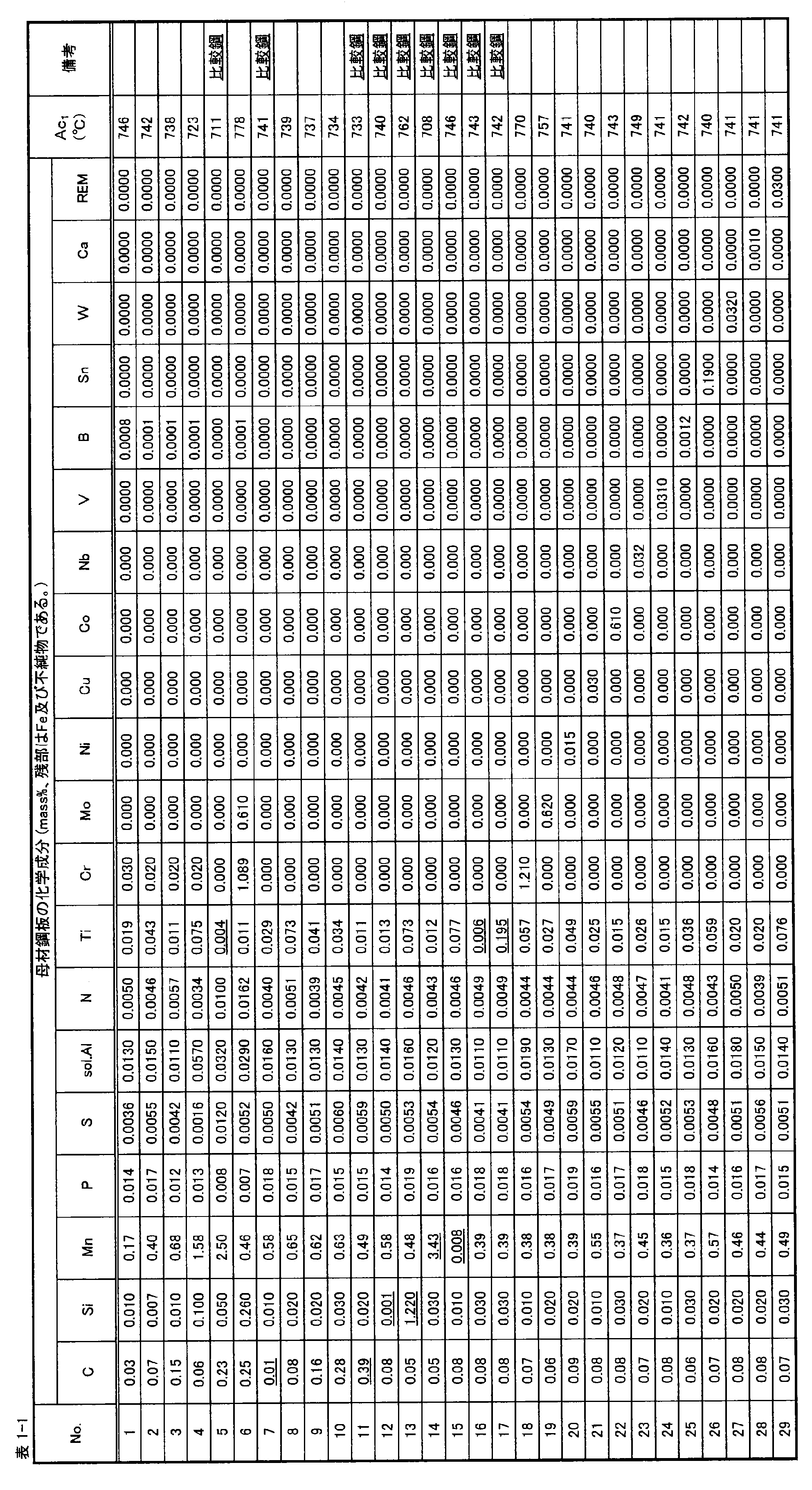
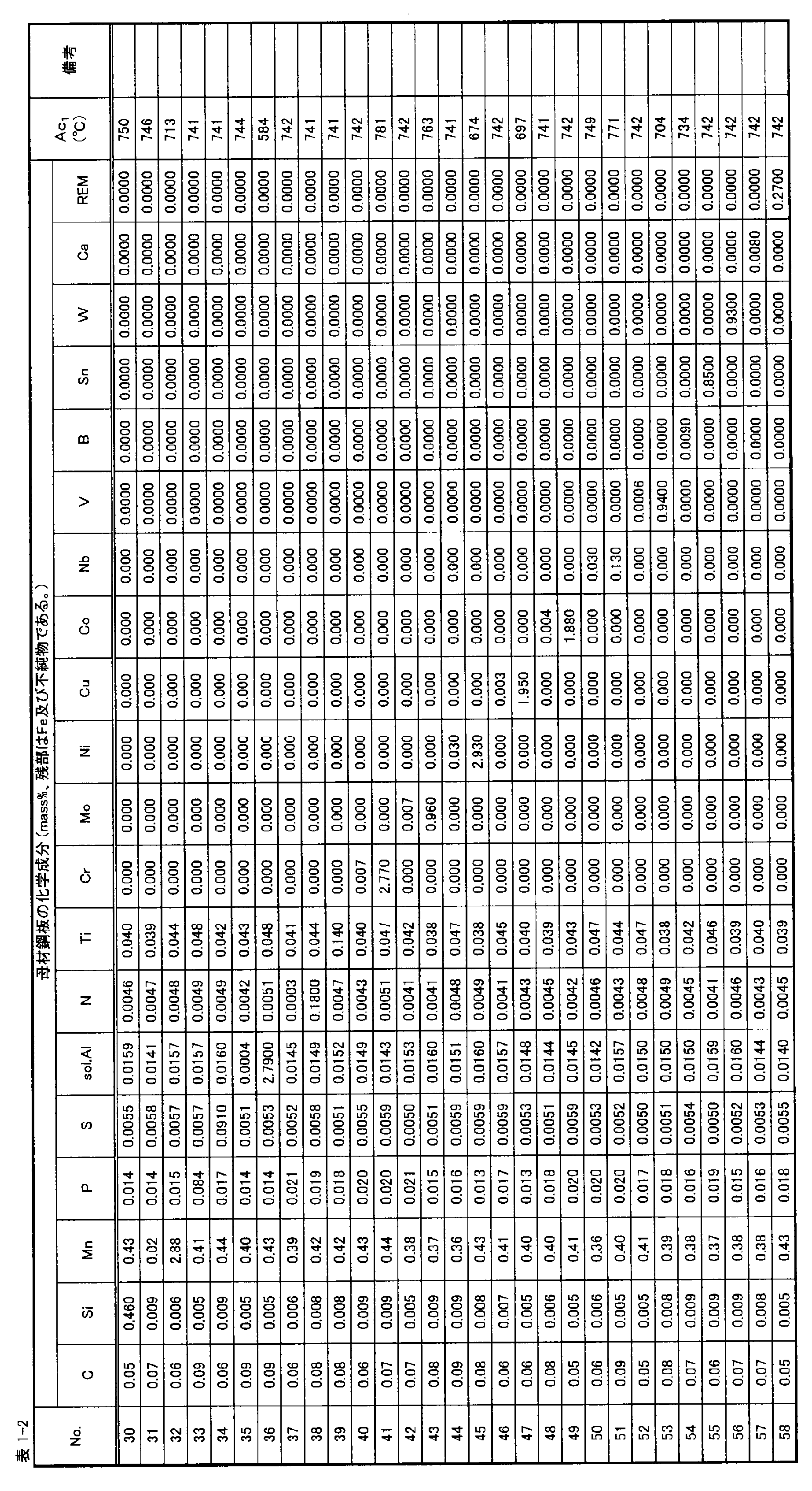
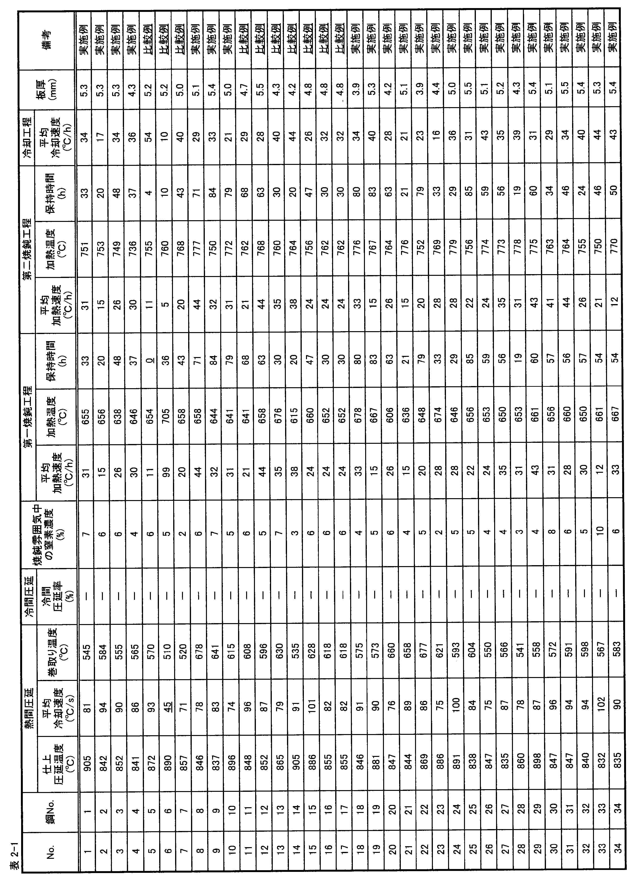
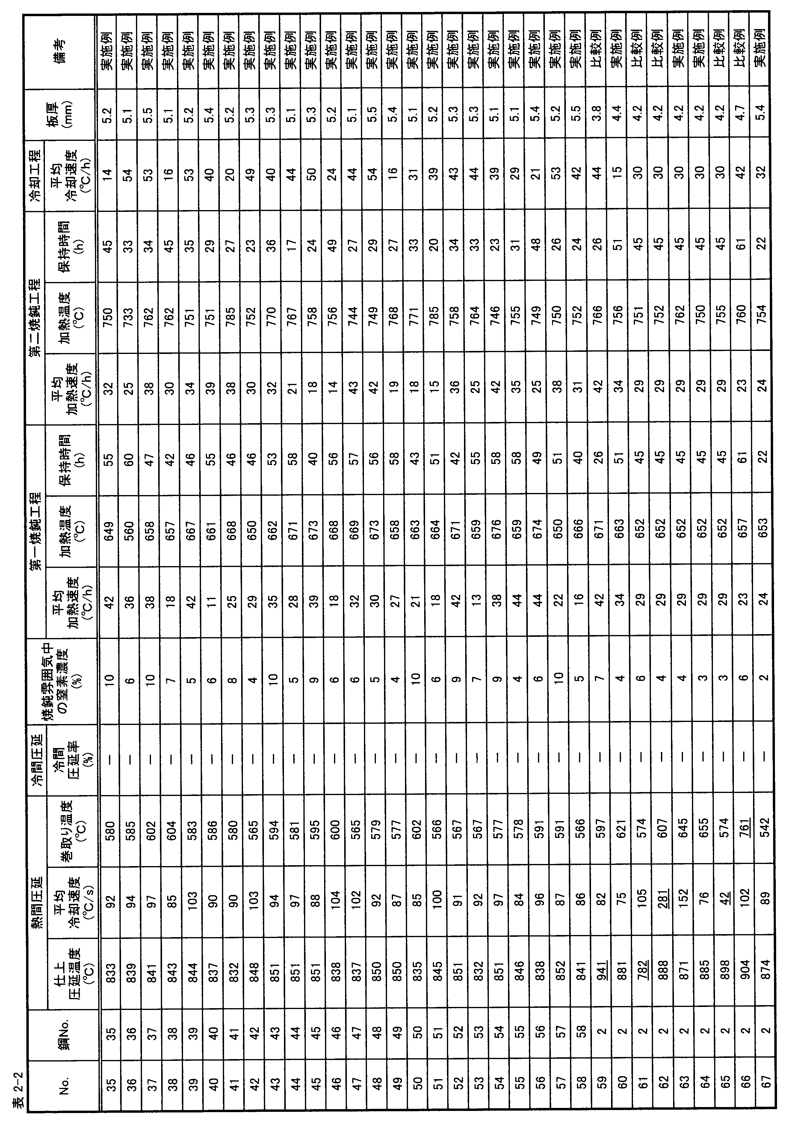


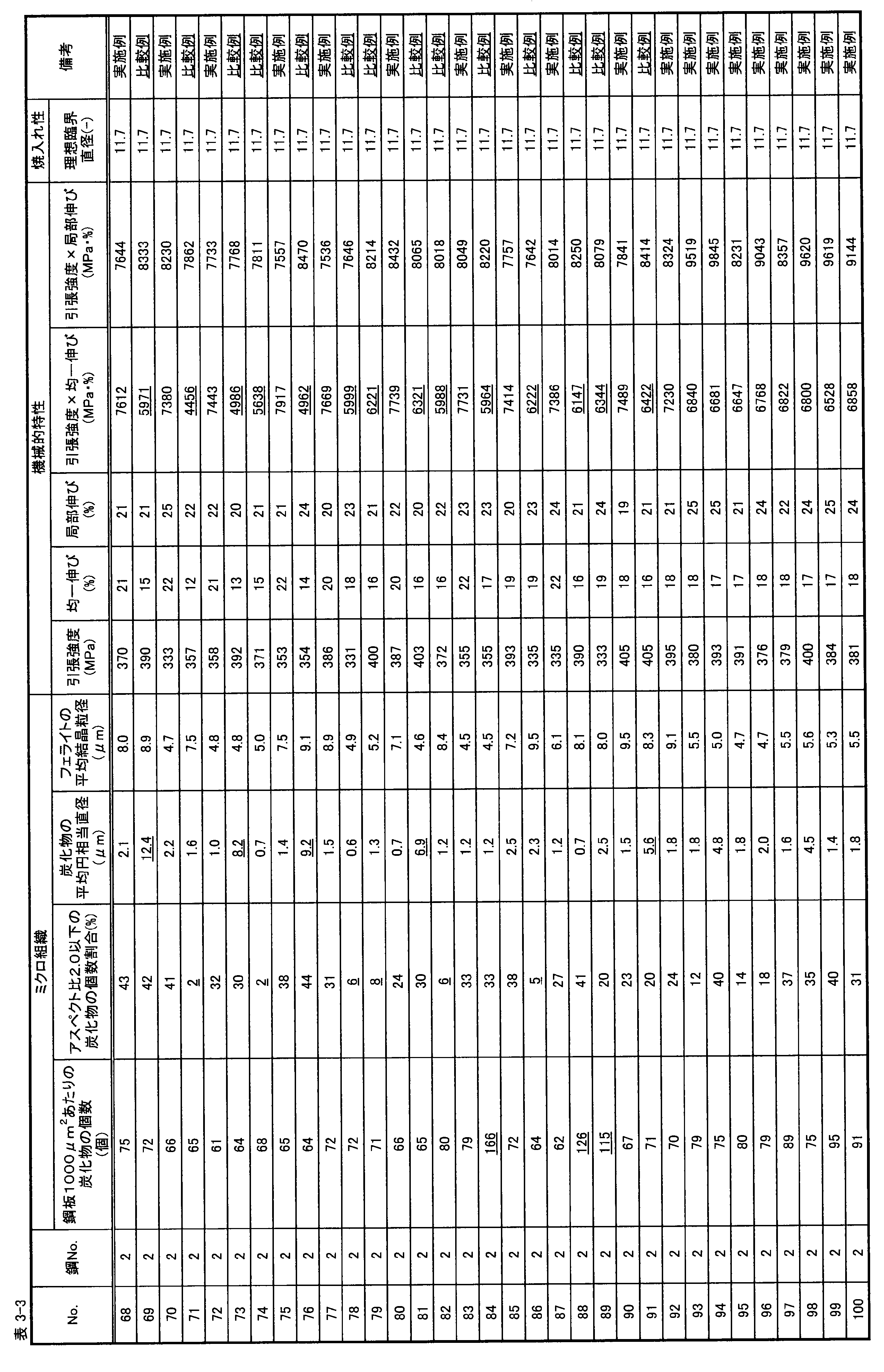
以下の表4に示す化学組成を有する鋼材を、以下の表5に示す条件で熱間圧延(及び冷間圧延)した後、焼鈍を施して、浸炭用鋼板を得た。本試験例では、熱間圧延工程と第一焼鈍工程との間で、上記のクラスター化処理を実施した浸炭用鋼板と、実施しなかった浸炭用鋼板とのそれぞれについて、検証を行った。なお、以下の表5に示した「冷却工程」における「平均冷却速度」は、第二焼鈍終了時の温度から550℃までの温度域における平均冷却速度である。また、クラスター化処理は、熱間圧延後の鋼板を、大気中、55℃で105時間保持することで実施した。以下の表5から明らかなように、クラスター化処理の有無以外は、ほぼ同じ条件となるように、各処理工程を実施した。


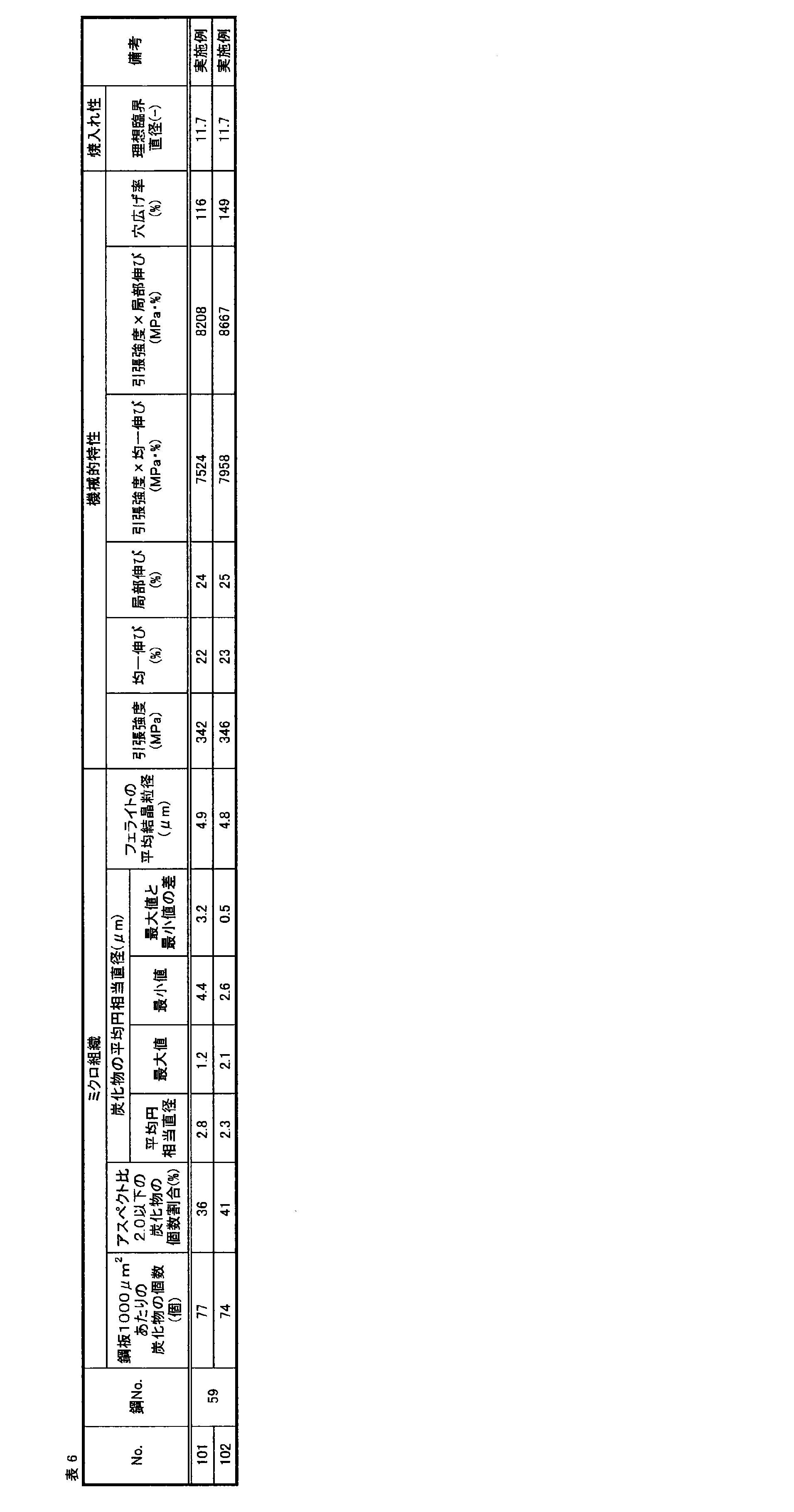
Claims (5)
- 質量%で、
C:0.02%以上0.30%未満
Si:0.005%以上0.5%未満
Mn:0.01%以上3.0%未満
P:0.1%以下
S:0.1%以下
sol.Al:0.0002%以上3.0%以下
N:0.2%以下
Ti:0.010%以上0.150%以下
を含有し、残部が、Fe及び不純物からなり、
1000μm2あたりの炭化物の個数が、100個以下であり、
アスペクト比が2.0以下である炭化物の個数割合が、全炭化物に対して10%以上であり、
炭化物の平均円相当直径が、5.0μm以下であり、
フェライトの平均結晶粒径が、10μm以下である、浸炭用鋼板。 - 残部のFeの一部に換えて、質量%で、
Cr:0.005%以上3.0%以下
Mo:0.005%以上1.0%以下
Ni:0.010%以上3.0%以下
Cu:0.001%以上2.0%以下
Co:0.001%以上2.0%以下
Nb:0.010%以上0.150%以下
V:0.0005%以上1.0%以下
B:0.0005%以上0.01%以下
の1種又は2種以上を更に含有する、請求項1に記載の浸炭用鋼板。 - 残部のFeの一部に換えて、質量%で、
Sn:1.0%以下
W:1.0%以下
Ca:0.01%以下
REM:0.3%以下
の1種又は2種以上を更に含有する、請求項1又は2に記載の浸炭用鋼板。 - 請求項1~3の何れか1項に記載の浸炭用鋼板を製造する方法であって、
請求項1~3の何れか1項に記載の化学組成を有する鋼材を加熱し、熱間仕上圧延を、800℃以上920℃未満の温度域で終了した後、熱間仕上圧延終了時の温度から冷却停止温度までの温度域を50℃/s以上250℃/s以下の平均冷却速度で冷却して、700℃以下の温度で巻取る熱間圧延工程と、
前記熱間圧延工程により得られた鋼板、又は、前記熱間圧延工程後に冷間圧延が施された鋼板を、窒素濃度を体積分率で25%未満に制御した焼鈍雰囲気にて、1℃/h以上100℃/h以下の平均加熱速度で、下記式(1)で定義されるAc1点以下の温度域まで加熱し、当該Ac1点以下の温度域で1h以上100h以下保持する第一焼鈍工程と、
前記第一焼鈍工程を経た鋼板を、前記1℃/h以上100℃/h以下の平均加熱速度で、下記式(1)で定義されるAc1点超790℃以下の温度域まで加熱し、当該Ac1点超790℃以下の温度域で1h以上100h以下保持する第二焼鈍工程と、
前記第二焼鈍工程での焼鈍後の鋼板に対して、前記第二焼鈍工程での焼鈍終了時の温度から550℃までの温度域における平均冷却速度を1℃/h以上100℃/h以下とする
冷却を施す冷却工程と、
を含む、浸炭用鋼板の製造方法。
ここで、下記式(1)において、[X]との表記は、元素Xの含有量(単位:質量%)を表し、該当する元素を含有しない場合はゼロを代入するものとする。

- 前記熱間圧延工程と前記第一焼鈍工程との間に、前記熱間圧延工程により得られた鋼板を、大気中、40℃以上70℃以下の温度で、72h以上350h以下保持する保持工程を更に含む、請求項4に記載の浸炭用鋼板の製造方法。
Priority Applications (7)
| Application Number | Priority Date | Filing Date | Title |
|---|---|---|---|
| BR112019008329-4A BR112019008329A2 (pt) | 2017-08-31 | 2018-08-30 | chapa de aço para carburação, e método de fabricação da chapa de aço para carburação |
| EP18852563.8A EP3517648A4 (en) | 2017-08-31 | 2018-08-30 | STEEL SHEET FOR CARBONING AND PRODUCTION METHOD FOR STEEL SHEET FOR CARBONING |
| MX2019004216A MX2019004216A (es) | 2017-08-31 | 2018-08-30 | Lamina de acero para carburacion, y metodo para fabricar la lamina de acero para carburacion. |
| US16/346,055 US11639536B2 (en) | 2017-08-31 | 2018-08-30 | Steel sheet for carburizing, and method for manufacturing steel sheet for carburizing |
| KR1020197012048A KR102235355B1 (ko) | 2017-08-31 | 2018-08-30 | 침탄용 강판, 및 침탄용 강판의 제조 방법 |
| CN201880004206.8A CN109923234B (zh) | 2017-08-31 | 2018-08-30 | 渗碳用钢板以及渗碳用钢板的制造方法 |
| JP2019518324A JP6583587B2 (ja) | 2017-08-31 | 2018-08-30 | 浸炭用鋼板、及び、浸炭用鋼板の製造方法 |
Applications Claiming Priority (2)
| Application Number | Priority Date | Filing Date | Title |
|---|---|---|---|
| JP2017167206 | 2017-08-31 | ||
| JP2017-167206 | 2017-08-31 |
Publications (1)
| Publication Number | Publication Date |
|---|---|
| WO2019044971A1 true WO2019044971A1 (ja) | 2019-03-07 |
Family
ID=65525472
Family Applications (1)
| Application Number | Title | Priority Date | Filing Date |
|---|---|---|---|
| PCT/JP2018/032112 Ceased WO2019044971A1 (ja) | 2017-08-31 | 2018-08-30 | 浸炭用鋼板、及び、浸炭用鋼板の製造方法 |
Country Status (9)
| Country | Link |
|---|---|
| US (1) | US11639536B2 (ja) |
| EP (1) | EP3517648A4 (ja) |
| JP (1) | JP6583587B2 (ja) |
| KR (1) | KR102235355B1 (ja) |
| CN (1) | CN109923234B (ja) |
| BR (1) | BR112019008329A2 (ja) |
| MX (1) | MX2019004216A (ja) |
| TW (1) | TWI658145B (ja) |
| WO (1) | WO2019044971A1 (ja) |
Cited By (1)
| Publication number | Priority date | Publication date | Assignee | Title |
|---|---|---|---|---|
| CN109881103A (zh) * | 2019-03-19 | 2019-06-14 | 潍坊工程职业学院 | 一种风电塔筒用法兰材料及其制备方法 |
Families Citing this family (8)
| Publication number | Priority date | Publication date | Assignee | Title |
|---|---|---|---|---|
| KR101988771B1 (ko) * | 2017-12-22 | 2019-09-30 | 주식회사 포스코 | 수소유기균열 저항성 및 길이방향 강도 균일성이 우수한 강판 및 그 제조방법 |
| CN113416894B (zh) * | 2021-05-25 | 2022-08-16 | 鞍钢股份有限公司 | 一种m65级电阻焊石油套管及其制造方法 |
| CN115404398A (zh) * | 2021-05-26 | 2022-11-29 | 拓普特(常州)机械有限公司 | 一种新型钢架的制备方法 |
| CN113403535B (zh) * | 2021-05-31 | 2022-05-20 | 北京首钢股份有限公司 | 一种车厢板用热轧带钢及其制备方法 |
| CN113403568A (zh) * | 2021-06-01 | 2021-09-17 | 温岭市云福热处理厂 | 一种低碳钢及其热处理工艺 |
| CN115044834A (zh) * | 2022-06-20 | 2022-09-13 | 西王金属科技有限公司 | 一种低合金高强度钢及制备方法 |
| CN117344232B (zh) * | 2022-06-29 | 2025-11-14 | 宝山钢铁股份有限公司 | 一种490MPa级心部高疲劳强度的厚钢板及其制造方法 |
| CN117026084B (zh) * | 2023-08-22 | 2024-11-05 | 青岛新力通工业有限责任公司 | 一种耐热合金及其制备方法 |
Citations (3)
| Publication number | Priority date | Publication date | Assignee | Title |
|---|---|---|---|---|
| JP2013018999A (ja) * | 2011-07-07 | 2013-01-31 | Nippon Steel & Sumitomo Metal Corp | 冷鍛窒化用鋼材 |
| WO2016148037A1 (ja) * | 2015-03-13 | 2016-09-22 | 株式会社神戸製鋼所 | 冷間加工性と浸炭熱処理後の靱性に優れる浸炭用鋼板 |
| WO2016190370A1 (ja) * | 2015-05-26 | 2016-12-01 | 新日鐵住金株式会社 | 鋼板及びその製造方法 |
Family Cites Families (13)
| Publication number | Priority date | Publication date | Assignee | Title |
|---|---|---|---|---|
| JPS56153217A (en) | 1980-04-30 | 1981-11-27 | Nippon Gakki Seizo Kk | Measuring device for reverberation characteristic |
| JP3094856B2 (ja) | 1995-08-11 | 2000-10-03 | 株式会社神戸製鋼所 | 高強度高靭性肌焼き用鋼 |
| TW514291U (en) | 2001-12-26 | 2002-12-11 | Shin-Jeng Tu | Improved structure of poster rack |
| JP5765092B2 (ja) * | 2010-07-15 | 2015-08-19 | Jfeスチール株式会社 | 延性と穴広げ性に優れた高降伏比高強度溶融亜鉛めっき鋼板およびその製造方法 |
| US9816153B2 (en) * | 2011-09-28 | 2017-11-14 | Jfe Steel Corporation | High strength steel sheet and method of manufacturing the same |
| JP6143355B2 (ja) | 2013-10-22 | 2017-06-07 | 株式会社神戸製鋼所 | 絞り加工性と浸炭熱処理後の表面硬さに優れる熱延鋼板 |
| PL3115475T3 (pl) * | 2014-03-07 | 2020-03-31 | Nippon Steel Corporation | Blacha cienka ze stali średnio-/wysokowęglowej i sposób jej wytwarzania |
| JP6177754B2 (ja) | 2014-11-18 | 2017-08-09 | 株式会社神戸製鋼所 | 打抜き性と結晶粒粗大化防止特性に優れた浸炭用鋼板および機械構造部品 |
| BR112017021482A2 (ja) * | 2015-04-10 | 2018-07-03 | Nippon Steel & Sumitomo Metal Corporation | A steel plate excellent in the cold work nature at the time of fabrication, and a manufacturing method for the same |
| JP6160783B2 (ja) * | 2015-05-26 | 2017-07-12 | 新日鐵住金株式会社 | 鋼板及びその製造方法 |
| EP3305930A4 (en) * | 2015-05-26 | 2018-12-05 | Nippon Steel & Sumitomo Metal Corporation | Steel sheet and method for producing same |
| US20180171445A1 (en) | 2015-06-17 | 2018-06-21 | Nippon Steel & Sumitomo Metal Corporation | Steel plate and method of production of same |
| JP6450652B2 (ja) | 2015-06-18 | 2019-01-09 | スズキ株式会社 | ウインドウレギュレータ |
-
2018
- 2018-08-30 EP EP18852563.8A patent/EP3517648A4/en not_active Withdrawn
- 2018-08-30 MX MX2019004216A patent/MX2019004216A/es unknown
- 2018-08-30 KR KR1020197012048A patent/KR102235355B1/ko active Active
- 2018-08-30 BR BR112019008329-4A patent/BR112019008329A2/pt not_active IP Right Cessation
- 2018-08-30 US US16/346,055 patent/US11639536B2/en active Active
- 2018-08-30 JP JP2019518324A patent/JP6583587B2/ja active Active
- 2018-08-30 WO PCT/JP2018/032112 patent/WO2019044971A1/ja not_active Ceased
- 2018-08-30 TW TW107130272A patent/TWI658145B/zh not_active IP Right Cessation
- 2018-08-30 CN CN201880004206.8A patent/CN109923234B/zh active Active
Patent Citations (3)
| Publication number | Priority date | Publication date | Assignee | Title |
|---|---|---|---|---|
| JP2013018999A (ja) * | 2011-07-07 | 2013-01-31 | Nippon Steel & Sumitomo Metal Corp | 冷鍛窒化用鋼材 |
| WO2016148037A1 (ja) * | 2015-03-13 | 2016-09-22 | 株式会社神戸製鋼所 | 冷間加工性と浸炭熱処理後の靱性に優れる浸炭用鋼板 |
| WO2016190370A1 (ja) * | 2015-05-26 | 2016-12-01 | 新日鐵住金株式会社 | 鋼板及びその製造方法 |
Non-Patent Citations (1)
| Title |
|---|
| See also references of EP3517648A4 * |
Cited By (1)
| Publication number | Priority date | Publication date | Assignee | Title |
|---|---|---|---|---|
| CN109881103A (zh) * | 2019-03-19 | 2019-06-14 | 潍坊工程职业学院 | 一种风电塔筒用法兰材料及其制备方法 |
Also Published As
| Publication number | Publication date |
|---|---|
| EP3517648A1 (en) | 2019-07-31 |
| TWI658145B (zh) | 2019-05-01 |
| CN109923234B (zh) | 2021-03-30 |
| EP3517648A4 (en) | 2020-03-11 |
| US11639536B2 (en) | 2023-05-02 |
| JP6583587B2 (ja) | 2019-10-02 |
| BR112019008329A2 (pt) | 2019-07-16 |
| KR20190062474A (ko) | 2019-06-05 |
| US20200181728A1 (en) | 2020-06-11 |
| KR102235355B1 (ko) | 2021-04-02 |
| CN109923234A (zh) | 2019-06-21 |
| TW201920695A (zh) | 2019-06-01 |
| MX2019004216A (es) | 2019-08-05 |
| JPWO2019044971A1 (ja) | 2019-11-07 |
Similar Documents
| Publication | Publication Date | Title |
|---|---|---|
| JP6583588B2 (ja) | 浸炭用鋼板、及び、浸炭用鋼板の製造方法 | |
| JP6583587B2 (ja) | 浸炭用鋼板、及び、浸炭用鋼板の製造方法 | |
| JP6587038B1 (ja) | 浸炭用鋼板、及び、浸炭用鋼板の製造方法 | |
| JP6160783B2 (ja) | 鋼板及びその製造方法 | |
| KR20170107057A (ko) | 고강도 냉연 강판 및 그의 제조 방법 | |
| WO2007000955A1 (ja) | 高炭素熱延鋼板およびその製造方法 | |
| WO2013102986A1 (ja) | 高炭素熱延鋼板およびその製造方法 | |
| WO2021070951A1 (ja) | 冷延鋼板およびその製造方法 | |
| JP5958668B1 (ja) | 高強度鋼板およびその製造方法 | |
| WO2021230149A1 (ja) | ホットスタンプ成形体 | |
| CN105102659A (zh) | 氮化处理用钢板及其制造方法 | |
| JP4740099B2 (ja) | 高強度冷延鋼板及びその製造方法 | |
| KR20130035276A (ko) | 강판 및 그 제조 방법 | |
| JP7846395B2 (ja) | 冷延鋼板およびその製造方法 | |
| JP2022122483A (ja) | 熱延鋼板およびその製造方法 | |
| JP7469706B2 (ja) | 高強度鋼板 | |
| JP2016216809A (ja) | 冷間成形性と熱処理後靭性に優れた低炭素鋼板及び製造方法 | |
| WO2007000954A1 (ja) | 高炭素冷延鋼板の製造方法 | |
| TWI665310B (zh) | 滲碳用鋼板及滲碳用鋼板的製造方法 | |
| JP6699711B2 (ja) | 高強度鋼帯の製造方法 | |
| JP2022051251A (ja) | 高炭素鋼板 | |
| JP3643556B2 (ja) | 強度異方性の無い高張力圧延鋼板およびその製造方法 | |
| JP2022050985A (ja) | 高炭素鋼部品 | |
| JP2022050984A (ja) | 高炭素鋼部品 |
Legal Events
| Date | Code | Title | Description |
|---|---|---|---|
| ENP | Entry into the national phase |
Ref document number: 2019518324 Country of ref document: JP Kind code of ref document: A |
|
| 121 | Ep: the epo has been informed by wipo that ep was designated in this application |
Ref document number: 18852563 Country of ref document: EP Kind code of ref document: A1 |
|
| ENP | Entry into the national phase |
Ref document number: 20197012048 Country of ref document: KR Kind code of ref document: A |
|
| REG | Reference to national code |
Ref country code: BR Ref legal event code: B01A Ref document number: 112019008329 Country of ref document: BR |
|
| ENP | Entry into the national phase |
Ref document number: 2018852563 Country of ref document: EP Effective date: 20190425 |
|
| ENP | Entry into the national phase |
Ref document number: 112019008329 Country of ref document: BR Kind code of ref document: A2 Effective date: 20190425 |
|
| NENP | Non-entry into the national phase |
Ref country code: DE |