WO2019044991A1 - 血管新生剤およびその製造方法 - Google Patents
血管新生剤およびその製造方法 Download PDFInfo
- Publication number
- WO2019044991A1 WO2019044991A1 PCT/JP2018/032162 JP2018032162W WO2019044991A1 WO 2019044991 A1 WO2019044991 A1 WO 2019044991A1 JP 2018032162 W JP2018032162 W JP 2018032162W WO 2019044991 A1 WO2019044991 A1 WO 2019044991A1
- Authority
- WO
- WIPO (PCT)
- Prior art keywords
- membrane
- porous membrane
- angiogenic agent
- mesenchymal stem
- cell
- Prior art date
- Legal status (The legal status is an assumption and is not a legal conclusion. Google has not performed a legal analysis and makes no representation as to the accuracy of the status listed.)
- Ceased
Links
Images









Classifications
-
- A—HUMAN NECESSITIES
- A61—MEDICAL OR VETERINARY SCIENCE; HYGIENE
- A61L—METHODS OR APPARATUS FOR STERILISING MATERIALS OR OBJECTS IN GENERAL; DISINFECTION, STERILISATION OR DEODORISATION OF AIR; CHEMICAL ASPECTS OF BANDAGES, DRESSINGS, ABSORBENT PADS OR SURGICAL ARTICLES; MATERIALS FOR BANDAGES, DRESSINGS, ABSORBENT PADS OR SURGICAL ARTICLES
- A61L27/00—Materials for grafts or prostheses or for coating grafts or prostheses
- A61L27/36—Materials for grafts or prostheses or for coating grafts or prostheses containing ingredients of undetermined constitution or reaction products thereof, e.g. transplant tissue, natural bone, extracellular matrix
- A61L27/38—Materials for grafts or prostheses or for coating grafts or prostheses containing ingredients of undetermined constitution or reaction products thereof, e.g. transplant tissue, natural bone, extracellular matrix containing added animal cells
- A61L27/3804—Materials for grafts or prostheses or for coating grafts or prostheses containing ingredients of undetermined constitution or reaction products thereof, e.g. transplant tissue, natural bone, extracellular matrix containing added animal cells characterised by specific cells or progenitors thereof, e.g. fibroblasts, connective tissue cells, kidney cells
- A61L27/3834—Cells able to produce different cell types, e.g. hematopoietic stem cells, mesenchymal stem cells, marrow stromal cells, embryonic stem cells
-
- A—HUMAN NECESSITIES
- A61—MEDICAL OR VETERINARY SCIENCE; HYGIENE
- A61F—FILTERS IMPLANTABLE INTO BLOOD VESSELS; PROSTHESES; DEVICES PROVIDING PATENCY TO, OR PREVENTING COLLAPSING OF, TUBULAR STRUCTURES OF THE BODY, e.g. STENTS; ORTHOPAEDIC, NURSING OR CONTRACEPTIVE DEVICES; FOMENTATION; TREATMENT OR PROTECTION OF EYES OR EARS; BANDAGES, DRESSINGS OR ABSORBENT PADS; FIRST-AID KITS
- A61F2/00—Filters implantable into blood vessels; Prostheses, i.e. artificial substitutes or replacements for parts of the body; Appliances for connecting them with the body; Devices providing patency to, or preventing collapsing of, tubular structures of the body, e.g. stents
- A61F2/02—Prostheses implantable into the body
- A61F2/04—Hollow or tubular parts of organs, e.g. bladders, tracheae, bronchi or bile ducts
- A61F2/06—Blood vessels
-
- A—HUMAN NECESSITIES
- A61—MEDICAL OR VETERINARY SCIENCE; HYGIENE
- A61K—PREPARATIONS FOR MEDICAL, DENTAL OR TOILETRY PURPOSES
- A61K35/00—Medicinal preparations containing materials or reaction products thereof with undetermined constitution
- A61K35/12—Materials from mammals; Compositions comprising non-specified tissues or cells; Compositions comprising non-embryonic stem cells; Genetically modified cells
- A61K35/28—Bone marrow; Haematopoietic stem cells; Mesenchymal stem cells of any origin, e.g. adipose-derived stem cells
-
- A—HUMAN NECESSITIES
- A61—MEDICAL OR VETERINARY SCIENCE; HYGIENE
- A61L—METHODS OR APPARATUS FOR STERILISING MATERIALS OR OBJECTS IN GENERAL; DISINFECTION, STERILISATION OR DEODORISATION OF AIR; CHEMICAL ASPECTS OF BANDAGES, DRESSINGS, ABSORBENT PADS OR SURGICAL ARTICLES; MATERIALS FOR BANDAGES, DRESSINGS, ABSORBENT PADS OR SURGICAL ARTICLES
- A61L27/00—Materials for grafts or prostheses or for coating grafts or prostheses
- A61L27/14—Macromolecular materials
- A61L27/16—Macromolecular materials obtained by reactions only involving carbon-to-carbon unsaturated bonds
-
- A—HUMAN NECESSITIES
- A61—MEDICAL OR VETERINARY SCIENCE; HYGIENE
- A61L—METHODS OR APPARATUS FOR STERILISING MATERIALS OR OBJECTS IN GENERAL; DISINFECTION, STERILISATION OR DEODORISATION OF AIR; CHEMICAL ASPECTS OF BANDAGES, DRESSINGS, ABSORBENT PADS OR SURGICAL ARTICLES; MATERIALS FOR BANDAGES, DRESSINGS, ABSORBENT PADS OR SURGICAL ARTICLES
- A61L27/00—Materials for grafts or prostheses or for coating grafts or prostheses
- A61L27/14—Macromolecular materials
- A61L27/18—Macromolecular materials obtained otherwise than by reactions only involving carbon-to-carbon unsaturated bonds
-
- A—HUMAN NECESSITIES
- A61—MEDICAL OR VETERINARY SCIENCE; HYGIENE
- A61L—METHODS OR APPARATUS FOR STERILISING MATERIALS OR OBJECTS IN GENERAL; DISINFECTION, STERILISATION OR DEODORISATION OF AIR; CHEMICAL ASPECTS OF BANDAGES, DRESSINGS, ABSORBENT PADS OR SURGICAL ARTICLES; MATERIALS FOR BANDAGES, DRESSINGS, ABSORBENT PADS OR SURGICAL ARTICLES
- A61L27/00—Materials for grafts or prostheses or for coating grafts or prostheses
- A61L27/14—Macromolecular materials
- A61L27/26—Mixtures of macromolecular compounds
-
- A—HUMAN NECESSITIES
- A61—MEDICAL OR VETERINARY SCIENCE; HYGIENE
- A61L—METHODS OR APPARATUS FOR STERILISING MATERIALS OR OBJECTS IN GENERAL; DISINFECTION, STERILISATION OR DEODORISATION OF AIR; CHEMICAL ASPECTS OF BANDAGES, DRESSINGS, ABSORBENT PADS OR SURGICAL ARTICLES; MATERIALS FOR BANDAGES, DRESSINGS, ABSORBENT PADS OR SURGICAL ARTICLES
- A61L27/00—Materials for grafts or prostheses or for coating grafts or prostheses
- A61L27/40—Composite materials, i.e. containing one material dispersed in a matrix of the same or different material
- A61L27/44—Composite materials, i.e. containing one material dispersed in a matrix of the same or different material having a macromolecular matrix
-
- A—HUMAN NECESSITIES
- A61—MEDICAL OR VETERINARY SCIENCE; HYGIENE
- A61L—METHODS OR APPARATUS FOR STERILISING MATERIALS OR OBJECTS IN GENERAL; DISINFECTION, STERILISATION OR DEODORISATION OF AIR; CHEMICAL ASPECTS OF BANDAGES, DRESSINGS, ABSORBENT PADS OR SURGICAL ARTICLES; MATERIALS FOR BANDAGES, DRESSINGS, ABSORBENT PADS OR SURGICAL ARTICLES
- A61L27/00—Materials for grafts or prostheses or for coating grafts or prostheses
- A61L27/50—Materials characterised by their function or physical properties, e.g. injectable or lubricating compositions, shape-memory materials, surface modified materials
-
- A—HUMAN NECESSITIES
- A61—MEDICAL OR VETERINARY SCIENCE; HYGIENE
- A61L—METHODS OR APPARATUS FOR STERILISING MATERIALS OR OBJECTS IN GENERAL; DISINFECTION, STERILISATION OR DEODORISATION OF AIR; CHEMICAL ASPECTS OF BANDAGES, DRESSINGS, ABSORBENT PADS OR SURGICAL ARTICLES; MATERIALS FOR BANDAGES, DRESSINGS, ABSORBENT PADS OR SURGICAL ARTICLES
- A61L27/00—Materials for grafts or prostheses or for coating grafts or prostheses
- A61L27/50—Materials characterised by their function or physical properties, e.g. injectable or lubricating compositions, shape-memory materials, surface modified materials
- A61L27/56—Porous materials, e.g. foams or sponges
-
- A—HUMAN NECESSITIES
- A61—MEDICAL OR VETERINARY SCIENCE; HYGIENE
- A61P—SPECIFIC THERAPEUTIC ACTIVITY OF CHEMICAL COMPOUNDS OR MEDICINAL PREPARATIONS
- A61P43/00—Drugs for specific purposes, not provided for in groups A61P1/00-A61P41/00
-
- A—HUMAN NECESSITIES
- A61—MEDICAL OR VETERINARY SCIENCE; HYGIENE
- A61P—SPECIFIC THERAPEUTIC ACTIVITY OF CHEMICAL COMPOUNDS OR MEDICINAL PREPARATIONS
- A61P9/00—Drugs for disorders of the cardiovascular system
-
- A—HUMAN NECESSITIES
- A61—MEDICAL OR VETERINARY SCIENCE; HYGIENE
- A61K—PREPARATIONS FOR MEDICAL, DENTAL OR TOILETRY PURPOSES
- A61K38/00—Medicinal preparations containing peptides
- A61K38/16—Peptides having more than 20 amino acids; Gastrins; Somatostatins; Melanotropins; Derivatives thereof
- A61K38/17—Peptides having more than 20 amino acids; Gastrins; Somatostatins; Melanotropins; Derivatives thereof from animals; from humans
- A61K38/39—Connective tissue peptides, e.g. collagen, elastin, laminin, fibronectin, vitronectin, cold insoluble globulin [CIG]
-
- A—HUMAN NECESSITIES
- A61—MEDICAL OR VETERINARY SCIENCE; HYGIENE
- A61K—PREPARATIONS FOR MEDICAL, DENTAL OR TOILETRY PURPOSES
- A61K47/00—Medicinal preparations characterised by the non-active ingredients used, e.g. carriers or inert additives; Targeting or modifying agents chemically bound to the active ingredient
- A61K47/30—Macromolecular organic or inorganic compounds, e.g. inorganic polyphosphates
- A61K47/32—Macromolecular compounds obtained by reactions only involving carbon-to-carbon unsaturated bonds, e.g. carbomers, poly(meth)acrylates, or polyvinyl pyrrolidone
-
- A—HUMAN NECESSITIES
- A61—MEDICAL OR VETERINARY SCIENCE; HYGIENE
- A61K—PREPARATIONS FOR MEDICAL, DENTAL OR TOILETRY PURPOSES
- A61K47/00—Medicinal preparations characterised by the non-active ingredients used, e.g. carriers or inert additives; Targeting or modifying agents chemically bound to the active ingredient
- A61K47/30—Macromolecular organic or inorganic compounds, e.g. inorganic polyphosphates
- A61K47/34—Macromolecular compounds obtained otherwise than by reactions only involving carbon-to-carbon unsaturated bonds, e.g. polyesters, polyamino acids, polysiloxanes, polyphosphazines, copolymers of polyalkylene glycol or poloxamers
-
- A—HUMAN NECESSITIES
- A61—MEDICAL OR VETERINARY SCIENCE; HYGIENE
- A61K—PREPARATIONS FOR MEDICAL, DENTAL OR TOILETRY PURPOSES
- A61K9/00—Medicinal preparations characterised by special physical form
- A61K9/48—Preparations in capsules, e.g. of gelatin, of chocolate
- A61K9/50—Microcapsules having a gas, liquid or semi-solid filling; Solid microparticles or pellets surrounded by a distinct coating layer, e.g. coated microspheres, coated drug crystals
-
- C—CHEMISTRY; METALLURGY
- C07—ORGANIC CHEMISTRY
- C07K—PEPTIDES
- C07K14/00—Peptides having more than 20 amino acids; Gastrins; Somatostatins; Melanotropins; Derivatives thereof
- C07K14/435—Peptides having more than 20 amino acids; Gastrins; Somatostatins; Melanotropins; Derivatives thereof from animals; from humans
- C07K14/78—Connective tissue peptides, e.g. collagen, elastin, laminin, fibronectin, vitronectin or cold insoluble globulin [CIG]
Definitions
- the present invention relates to an angiogenic agent comprising mesenchymal stem cells and an immunoisolation membrane encapsulating mesenchymal stem cells.
- the invention further relates to a method of producing an angiogenic agent.
- Patent Document 1 discloses a method for preventing / treating inflammatory bowel disease by intravenously administering MSC.
- Several clinical studies and clinical trials are also being conducted. However, it has been found that, in practice, sufficient therapeutic effects have not been shown (Non-patent Document 1).
- Patent Document 2 discloses a method for treating liver diseases by administering hypoxic cultured MSCs.
- Patent Document 3 discloses that MSC cultured in a simulated microgravity environment is suitable for treatment of central nervous system diseases. Furthermore, the angiogenic use for ischemic diseases is widely studied.
- Patent Document 4 discloses a therapeutic agent for ischemic limb disease containing adipose-derived mesenchymal stem cells.
- Patent Document 5 discloses an immunoisolation membrane device for implanting a pancreatic islet producing insulin, but does not disclose a method for implanting MSC.
- Patent Document 6 discloses an implantable device for providing a biologically active substance to a subject in need thereof, wherein the biocompatible device encapsulates one or more cells capable of producing the biologically active substance.
- a device with a microvascular structure in contact with a semipermeable pouch of sex is described.
- the device described in Patent Document 6 is for improving the viability and function of transplanted cells, and it is described that the device may be an immunoisolation device.
- Patent No. 5600 008 Patent No. 5290281 gazette Japanese Patent Publication No. 7-508187 JP 2008-41953 A
- the present invention solves the problem of providing an angiogenic agent capable of sufficiently exerting an angiogenic effect by mesenchymal stem cells in a state protected from immune rejection without permeating host cells, and a method for producing the same. It was an issue to be done.
- the present inventor included mesenchymal stem cells in an immunoisolation membrane to protect the immune rejection reaction from the angiogenic effect of mesenchymal stem cells. It has been found that an angiogenic agent that can be sufficiently exerted can be provided, and the present invention has been completed.
- An angiogenic agent comprising (1) (A) mesenchymal stem cells, and (B) an immunoisolation membrane encapsulating the mesenchymal stem cells.
- the angiogenic agent according to (3) wherein the minimum pore size of the porous membrane is 0.02 ⁇ m to 1.5 ⁇ m.
- the porous membrane has a layered dense portion in which the pore diameter is minimized, and the pore diameter continuously increases in the thickness direction from the dense portion toward at least one surface of the porous membrane.
- the mesenchymal stem cells comprise a plurality of biocompatible polymer blocks and at least one type of a plurality of mesenchymal stem cells, and at least one gap between the plurality of mesenchymal stem cells
- the angiogenesis agent according to any one of (1) to (9), which is contained as a cell structure in which the biocompatibility polymer block is disposed.
- a cell transplantation device comprising (A) mesenchymal stem cells and (B) an immunoisolation membrane encapsulating the above mesenchymal stem cells into a subject requiring angiogenesis Methods of angiogenesis.
- a device for cell transplantation for use in a treatment for angiogenesis comprising: (A) mesenchymal stem cells, and (B) an immunoisolation membrane encapsulating the above mesenchymal stem cells.
- Device Use of a device for cell transplantation comprising (A) mesenchymal stem cells, and (B) an immunoisolation membrane encapsulating the above mesenchymal stem cells, for the production of an angiogenic agent.
- the angiogenic agent of the present invention is useful in transplanting allogeneic or xenogeneic mesenchymal stem cells (MSC) causing immune rejection to promote angiogenesis. According to the present invention, it is possible to sufficiently exert the angiogenic effect by MSC while protecting MSC from host cells. According to the present invention, it is further possible to generate blood vessels locally and highly efficiently around the angiogenic agent.
- MSC mesenchymal stem cells
- FIG. 1 shows solution temperature profiling of the experiment described in condition A.
- FIG. 2 shows solution temperature profiling of the experiment described in condition B.
- FIG. 3 shows solution temperature profiling of the experiment described in condition C.
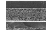
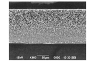
- FIG. 4 shows a SEM photograph of the cross section of the porous membrane of Reference Example 8.
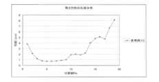
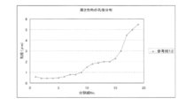
- FIG. 5 shows the pore size distribution in the thickness direction of the porous membrane of Reference Example 8.
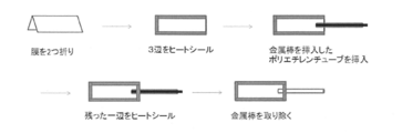
- FIG. 6 shows a method for producing a device for cell transplantation (immune isolation membrane only).
- FIG. 7 shows a SEM photograph of the cross section of the porous membrane of Reference Example 10.
- FIG. 8 shows the pore size distribution in the thickness direction of the porous membrane of Reference Example 10.
- FIG. 9 shows a SEM photograph of the cross section of the porous membrane of Reference Example 12.
- FIG. 10 shows the pore size distribution in the thickness direction of the porous membrane of Reference Example 12.
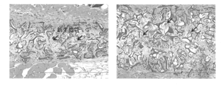
- FIG. 11 shows a tissue sample to which a device for cell transplantation containing cell structures has been transplanted.
- FIG. 12 shows a tissue sample transplanted with only cell structures.
- FIG. 13 shows a tissue sample to which a device for cell transplantation (immune isolation membrane only) was transplanted.
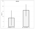
- FIG. 14 shows the measurement results of the total area of blood vessels per field of view.
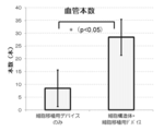
- FIG. 15 shows the measurement results of the number of blood vessels per field of view.
- FIG. 16 shows the measurement results of the total area of blood vessels per field of view.
- FIG. 17 shows the measurement results of the number of blood vessels per field of view.
- FIG. 18 shows a tissue sample of a C57BL / 6 mouse to which a device for cell transplantation containing a cell structure or a device for cell transplantation (immune isolation membrane only) was implanted.
- FIG. 19 shows a tissue preparation of C57BL / 6 mice implanted with only a device for cell transplantation.
- FIG. 20 shows the measurement results of the total area of blood vessels per field of view.
- FIG. 21 shows the measurement results of the number of blood vessels per field of view.
- the angiogenic agent of the present invention comprises (A) mesenchymal stem cells, and (B) an immunoisolation membrane encapsulating the mesenchymal stem cells.
- the angiogenic agent of the present invention can locally generate blood vessels around the angiogenic agent, and can exert a long-term therapeutic effect by the transplanted cells.
- the angiogenesis agent of the present invention per se does not contain microvessels, which differs from the device described in Patent Document 6 in this respect.
- the microvessel itself is the target of rejection by the host's immune reaction. It becomes. This is particularly pronounced when the microvessels contain cells, and Patent Document 6 also describes that allogeneic syngeney is used in consideration of that.
- the angiogenic agent of the present invention differs greatly in that it can be used without such limitations because it does not contain externally-derived microvessels and causes only new blood vessels to be created by host cells.
- the cells used in the present invention are mesenchymal stem cells (MSCs).
- MSCs mesenchymal stem cells
- the origin of mesenchymal stem cells is not particularly limited, but fat-derived mesenchymal stem cells or bone marrow-derived mesenchymal stem cells are preferable, and fat-derived mesenchymal stem cells are more preferable.
- Mesenchymal stem cells refer to somatic stem cells present in mesenchymal tissues and have the ability to differentiate into cells belonging to mesenchymal tissues.
- Mesenchymal tissue means tissues such as bone, cartilage, fat, blood, bone marrow, skeletal muscle, dermis, ligament, tendon, heart and the like.
- the cells used in the present invention may be used as they are, but may be used as cell structures.
- the cell structure referred to in the present specification includes a plurality of biocompatibility polymer blocks and at least one plurality of cells, and at least one of the above-mentioned bioaffinities in the gaps between the plurality of cells. It is a cell structure in which a polymer block is arranged.
- the cell structure may be referred to herein as a mosaic cell mass (cell mass in mosaic form).
- Biocompatible polymer block (1-1) Biocompatible polymer With biocompatibility, when it comes in contact with a living body, it causes a noticeable adverse reaction such as a long-term chronic inflammation reaction etc. It means not to do.
- the biocompatible polymer used in the present invention is not particularly limited as long as it is degraded in the living body as long as it has an affinity to the living body, but is preferably a biodegradable polymer.
- Specific examples of non-biodegradable materials include polytetrafluoroethylene (PTFE), polyurethane, polypropylene, polyester, vinyl chloride, polycarbonate, acrylic, stainless steel, titanium, silicone, and MPC (2-methacryloyloxyethyl phosphorylcholine). It can be mentioned.
- biodegradable materials include naturally occurring peptides, polypeptides such as recombinant peptides or chemically synthesized peptides (eg, gelatin described below), polylactic acid, polyglycolic acid, lactic acid / glycolic acid copolymer (PLGA), hyaluronic acid, glycosaminoglycan, proteoglycan, chondroitin, cellulose, agarose, carboxymethylcellulose, chitin, chitosan and the like.
- recombinant peptides are particularly preferred.
- These biocompatibility polymers may be designed to improve cell adhesion.
- a cell adhesion substrate (fibronectin, vitronectin, laminin) to a substrate surface or a cell adhesion sequence (represented by a single amino acid code, RGD sequence, LDV sequence, REDV sequence, YIGSR sequence, PDSGR sequence, RYVVLPR sequence) , Coating with LGTIPG sequence, RNIAEIIKDI sequence, IKVAV sequence, LRE sequence, DGEA sequence, and HAV sequence) peptide, "amination of substrate surface, cationization", or "plasma treatment of substrate surface, hydrophilicity by corona discharge” Methods such as sex processing can be used.
- polypeptide containing recombinant peptide or chemically synthesized peptide is not particularly limited as long as it has biocompatibility, but, for example, gelatin, collagen, atelocollagen, elastin, fibronectin, pronectin, laminin, tenascin, fibrin, fibroin, entactin , Thrombospondin and RetroNectin (registered trademark) are preferred, and most preferred are gelatin, collagen and atelocollagen.
- the gelatin for use in the present invention is preferably natural gelatin, recombinant gelatin or chemically synthesized gelatin, and more preferably recombinant gelatin.
- natural gelatin means gelatin made from collagen of natural origin.
- chemically synthesized peptide or chemically synthesized gelatin is meant an artificially synthesized peptide or gelatin.
- the synthesis of the peptide such as gelatin may be solid phase synthesis or liquid phase synthesis, but is preferably solid phase synthesis.
- Solid phase synthesis of peptides is known to the person skilled in the art, for example Fmoc group synthesis using Fmoc group (Fluorenyl-Methoxy-Carbonyl group) as protection of amino group, as well as Boc group (tert-Butyl as protection of amino group A Boc group synthesis method using an Oxy Carbonyl group) and the like can be mentioned.
- the preferred embodiments of chemically synthesized gelatin can be applied to the contents described in recombinant gelatin described later in this specification.
- the hydrophilicity value "1 / IOB" value of the biocompatible polymer is preferably from 0 to 1.0. More preferably, it is 0 to 0.6, and more preferably 0 to 0.4.
- the IOB is an indicator of hydrophilicity / hydrophobicity based on an organic conceptual diagram representing the polarity / non-polarity of the organic compound proposed by Atsushi Fujita, and the details are described in, for example, "Pharmaceutical Bulletin", vol. 2, 2, pp .163-173 (1954), “Domain of Chemistry” vol. 11, 10, pp. 719-725 (1957), “Fragrance Journal", vol. 50, pp. 79-82 (1981), etc. There is.
- the source of all organic compounds is methane (CH 4 ), and all the other compounds are regarded as derivatives of methane, and their carbon numbers, substituents, modified parts, rings, etc. are set to certain numerical values.
- the scores are added to obtain the organic value (OV) and the inorganic value (IV), and this value is plotted on the diagram with the organic value on the X axis and the inorganic value on the Y axis. It is something.
- the IOB in the organic conceptual diagram means the ratio of the inorganic value (IV) to the organic value (OV) in the organic conceptual diagram, that is, "inorganic value (IV) / organic value (OV)".
- hydrophilicity is expressed by "1 / IOB” value which is the reciprocal of IOB. The smaller the “1 / IOB” value (closer to 0), the more hydrophilic the expression.
- the hydrophilicity is high and the water absorbability is high, so it effectively acts on the retention of the nutritional component, and as a result, the present invention It is presumed that this contributes to the stabilization and survival of cells in the cell structure (mosaic cell mass).
- the hydrophilic / hydrophobicity index represented by Grand average of hydropathicity (GRAVY) value is preferably 0.3 or less, preferably -9.0 or more, and 0.0 or less More preferably, it is ⁇ 7.0 or more.
- Grand average of hydropathicity (GRAVY) values can be obtained from Gasteiger E., Hoogland C., Gattiker A., Duvaud S., Wilkins MR, Appel RD, Bairoch A .; Protein Identification and Analysis Tools on the ExPASy Server; (In) John M. Walker (ed): The Proteomics Protocols Handbook, Humana Press (2005). Pp.
- the hydrophilicity is high and the water absorbability is high, so it effectively acts on the retention of the nutrient component, and as a result, the cell structure according to the present invention It is presumed to contribute to the stabilization and survival of cells in the body (mosaic cell mass).
- the biocompatible polymer may or may not be crosslinked, but is preferably crosslinked.
- a cross-linked biocompatibility polymer By using a cross-linked biocompatibility polymer, an effect of preventing instantaneous decomposition when cultured in a medium and when transplanted to a living body can be obtained.
- Common crosslinking methods include thermal crosslinking, crosslinking with aldehydes (eg, formaldehyde, glutaraldehyde, etc.), crosslinking with condensing agents (carbodiimide, cyanamide, etc.), enzymatic crosslinking, photocrosslinking, ultraviolet crosslinking, hydrophobic interaction, Hydrogen bonds, ionic interactions and the like are known, and the above crosslinking method can be used in the present invention as well.
- the crosslinking method used in the present invention is more preferably thermal crosslinking, ultraviolet crosslinking or enzyme crosslinking, and particularly preferably thermal crosslinking.
- the enzyme When performing crosslinking by an enzyme, the enzyme is not particularly limited as long as it has a crosslinking action between polymer materials, but preferably, crosslinking can be performed using transglutaminase or laccase, most preferably transglutaminase .
- a specific example of the protein which is enzymatically crosslinked by transglutaminase is not particularly limited as long as it is a protein having a lysine residue and a glutamine residue.
- the transglutaminase may be of mammalian origin or of microbial origin.
- Ajinomoto's Activa series mammalian transglutaminase sold as a reagent, for example, Oriental Yeast Co., Ltd., Upstate USA Inc., Biodesign International and other guinea pig liver-derived transglutaminases, goat-derived transglutaminases, rabbit-derived transglutaminases, etc., and human-derived blood coagulation factors (Factor XIIIa, Haematologic Technologies, Inc.) and the like.
- the reaction temperature at the time of crosslinking is not particularly limited as long as crosslinking is possible, but is preferably ⁇ 100 ° C. to 500 ° C., more preferably 0 ° C. to 300 ° C., further preferably C. to 300.degree. C., particularly preferably 100.degree. C. to 250.degree. C., most preferably 120.degree. C. to 200.degree.
- Recombinant gelatin means a polypeptide or a protein-like substance having a gelatin-like amino acid sequence produced by genetic engineering technology.
- the recombinant gelatin which can be used in the present invention is preferably one having a repeat of the sequence represented by Gly-XY characteristic of collagen (X and Y each independently represent any amino acid).
- the plurality of Gly-X-Y may be the same or different.
- two or more sequences of cell adhesion signals are contained in one molecule.
- recombinant gelatin used in the present invention recombinant gelatin having an amino acid sequence derived from a partial amino acid sequence of collagen can be used.
- the recombinant gelatin used in the present invention is a recombinant gelatin of the following aspect.
- the recombinant gelatin is excellent in biocompatibility due to the natural performance of natural gelatin, and is not of natural origin, so there is no concern such as bovine spongiform encephalopathy (BSE) and is excellent in noninfectiousness.
- BSE bovine spongiform encephalopathy
- the recombinant gelatin is more uniform than the natural gelatin and the sequence is determined, it is possible to design the blur less precisely by the cross-linking and the like also in the strength and the degradability.
- the molecular weight of the recombinant gelatin is not particularly limited, but is preferably 2000 or more and 100000 or less (2 kDa (kilodalton) or more and 100 kDa or less), more preferably 2500 or more and 95000 or less (2.5 kDa or more and 95 kDa or less) Is 5000 or more and 90000 or less (5 kDa or more and 90 kDa or less), and most preferably 10000 or more and 90000 or less (10 kDa or more and 90 kDa or less).
- the recombinant gelatin preferably has a repeat of the sequence shown by Gly-XY characteristic of collagen.
- the plurality of Gly-X-Y may be the same or different.
- Gly-XY Gly represents glycine
- X and Y represent any amino acids (preferably, any amino acids other than glycine).
- the sequence represented by Gly-XY, which is characteristic of collagen, is a highly specific partial structure in the amino acid composition and sequence of gelatin-collagen as compared with other proteins. In this part, glycine accounts for about one third of the whole, and in the amino acid sequence, one out of every three repeats.
- Glycine is the simplest amino acid, has less restriction on the arrangement of molecular chains, and greatly contributes to regeneration of the helical structure upon gelation.
- the amino acids represented by X and Y contain a large amount of imino acids (proline and oxyproline), and preferably account for 10% to 45% of the total.
- at least 80%, more preferably at least 95%, most preferably at least 99% of the amino acids of the recombinant gelatin sequence are the repeated structure of Gly-XY.
- common polar amino acids are charged and uncharged at 1: 1.
- polar amino acids specifically refer to cysteine, aspartic acid, glutamic acid, histidine, lysine, asparagine, glutamine, serine, threonine, tyrosine and arginine
- polar uncharged amino acids among these include cysteine, asparagine, glutamine, serine , Threonine and tyrosine.
- the proportion of polar amino acids is 10 to 40%, preferably 20 to 30%, of the total amino acids constituting the composition.
- the ratio of the uncharged amino acid in the said polar amino acid is 5% or more and less than 20%, Preferably 5% or more and less than 10%. Furthermore, it is preferable not to include any one amino acid, preferably two or more amino acids of serine, threonine, asparagine, tyrosine and cysteine on the sequence.
- the minimum amino acid sequence that works as a cell adhesion signal is known (eg, “Pathophysiology” Vol. 9, No. 7 (1990) page 527) published by Nagai Publishing Co., Ltd.
- the recombinant gelatin used in the present invention preferably has two or more of these cell adhesion signals in one molecule.
- Specific sequences include RGD sequence, LDV sequence, REDV sequence, YIGSR sequence, PDSGR sequence, RYVVLPR sequence, LGTIPG sequence, RNIAEIIKDI sequence, which is expressed by single-letter amino acid notation in that there are many types of cells to adhere.
- the sequences of IKVAV, LRE, DGEA and HAV are preferred.
- RGD sequences More preferred are RGD sequences, YIGSR sequences, PDSGR sequences, LGTIPG sequences, IKVAV sequences and HAV sequences, and particularly preferred are RGD sequences.
- RGD sequences preferred are ERGD sequences.
- the number of amino acids between RGDs is preferably not uniform between 0 and 100, and more preferably, the number of amino acids between RGDs is not uniform between 25 and 60.
- the content of this minimal amino acid sequence is preferably 3 to 50, more preferably 4 to 30, and particularly preferably 5 to 20 in one molecule of protein from the viewpoint of cell adhesion and proliferation. And most preferably twelve.
- the ratio of the RGD motif to the total number of amino acids is preferably at least 0.4%. Where the recombinant gelatin comprises more than 350 amino acids, it is preferred that each stretch of 350 amino acids comprises at least one RGD motif.
- the ratio of RGD motif to the total number of amino acids is more preferably at least 0.6%, still more preferably at least 0.8%, still more preferably at least 1.0%, particularly preferably at least 1.2. %, Most preferably at least 1.5%.
- the number of RGD motifs in the recombinant peptide is preferably at least 4, more preferably at least 6, more preferably at least 8, particularly preferably 12 or more and 16 or less per 250 amino acids.
- a percentage of 0.4% of the RGD motif corresponds to at least one RGD sequence per 250 amino acids. Because the number of RGD motifs is an integer, gelatin consisting of 251 amino acids must contain at least two RGD sequences in order to meet the 0.4% feature.
- the recombinant gelatin comprises at least 2 RGD sequences per 250 amino acids, more preferably at least 3 RGD sequences per 250 amino acids, even more preferably at least 4 RGD sequences per 250 amino acids. Including.
- a further embodiment of the recombinant gelatin preferably comprises at least 4 RGD motifs, more preferably comprises at least 6 RGD motifs, still more preferably comprises at least 8 RGD motifs, particularly preferably 12 or more and 16 or less RGD motifs including.
- the recombinant gelatin may be partially hydrolyzed.
- the recombinant gelatin is that represented by Formula 1: A-[(Gly-X-Y) n ] m -B.
- the n X's each independently represent any of the amino acids
- the n Y's each independently represent any of the amino acids.
- m preferably represents an integer of 2 to 10, more preferably an integer of 3 to 5.
- n is preferably an integer of 3 to 100, more preferably an integer of 15 to 70, and most preferably an integer of 50 to 65.
- A represents any amino acid or amino acid sequence
- B represents any amino acid or amino acid sequence.
- the n pieces of Gly-X-Y may be the same or different.
- the recombinant gelatin is Gly-Ala-Pro-[(Gly-XY) 63 ] 3 -Gly, wherein each of 63 Xs independently represents any one of amino acids, and 63 Ys. Each independently represents any amino acid, and the 63 Gly-X-Y groups may be the same or different.
- the naturally occurring collagen referred to here may be any naturally occurring collagen, but is preferably type I, II, III, IV or V collagen. More preferably, it is type I, type II or type III collagen. According to another form, the collagen is preferably human, bovine, porcine, murine or rat, more preferably human.
- the isoelectric point of the recombinant gelatin is preferably 5 to 10, more preferably 6 to 10, and still more preferably 7 to 9.5.
- the measurement of the isoelectric point of recombinant gelatin was described in Isoelectric focusing (Maxey, CR (1976; Phitogr. Gelatin 2, Editor Cox, P. J. Academic, London, Engl.). Thus, it can be carried out by measuring the pH after passing a 1% by mass gelatin solution through a mixed crystal column of cation and anion exchange resin.
- the recombinant gelatin is not deaminated.
- the recombinant gelatin does not have telopentide.
- the recombinant gelatin is a substantially pure polypeptide prepared by a nucleic acid encoding an amino acid sequence.
- a peptide consisting of the amino acid sequence set forth in SEQ ID NO: 1; (2) An amino acid sequence in which one or several amino acids are deleted, substituted or added in the amino acid sequence of SEQ ID NO: 1, and a peptide having biocompatibility; or (3) SEQ ID NO: 1
- a peptide comprising an amino acid sequence having a sequence identity of 80% or more (more preferably 90% or more, particularly preferably 95% or more, most preferably 98% or more) with an amino acid sequence, and having biocompatibility; It is either.
- amino acid sequence in which one or several amino acids are deleted, substituted or added is preferably 1 to 20, more preferably 1 to 10, still more preferably 1 to 5 It means one, particularly preferably 1 to 3.
- the recombinant gelatin can be produced by gene recombination technology known to those skilled in the art, and for example, according to the method described in EP1014176A2, U.S. Pat. No. 6,992,172, WO 2004/85473, WO 2008/103041, etc. It can manufacture according to the same. Specifically, a gene encoding an amino acid sequence of a predetermined recombinant gelatin is obtained and incorporated into an expression vector to prepare a recombinant expression vector, which is introduced into an appropriate host to prepare a transformant. . Since the recombinant gelatin is produced by culturing the obtained transformant in an appropriate medium, the recombinant gelatin used in the present invention can be prepared by recovering the recombinant gelatin produced from the culture. .
- a block (mass) composed of the above-described biocompatibility polymer can be used.
- the shape of the biocompatible polymer block in the present invention is not particularly limited. For example, amorphous, spherical, particulate (granular), powdery, porous, fibrous, spindle-like, flat and sheet-like, preferably amorphous, spherical, particulate (granular), powdery And porous.
- the term "amorphous" indicates that the surface shape is not uniform, and for example, it indicates a rock-like uneven surface.
- the illustration of said shape is not a separate thing, respectively, For example, it may become an indeterminate form as an example of the lower concept of a particulate-form (granule).
- the shape of the biocompatible polymer block in the present invention is not particularly limited as described above, but the tap density is preferably 10 mg / cm 3 or more and 500 mg / cm 3 or less, more preferably 20 mg / cm 3 It is 400 mg / cm 3 or less, more preferably 40 mg / cm 3 or more and 220 mg / cm 3 or less, and particularly preferably 50 mg / cm 3 or more and 150 mg / cm 3 or less.
- the tap density is a value representing how many blocks can be packed in a certain volume, and the smaller the value, the tighter the packing can not be, that is, the structure of the block is complicated.
- the tap density of the biocompatibility polymer block represents the complexity of the surface structure of the biocompatibility polymer block and the amount of voids formed when the biocompatibility polymer block is collected as an assembly. it is conceivable that. The smaller the tap density, the more the voids between the biocompatible polymer blocks, and the more the cell engraftment area. Also, by not being too small, a bioaffinity polymer block can be appropriately present between cells, and nutrient delivery inside the same structure is possible when the cell structure is made, so the above range It is considered preferable to fit within
- the tap density as used herein is not particularly limited, but can be measured as follows.
- a container hereinafter referred to as a cap
- a cap of (cylindrical with a diameter of 6 mm and a length of 21.8 mm: a capacity of 0.616 cm 3 ) is prepared for measurement.
- the tap density can be determined by calculating the mass of the block alone from the difference between the mass of the cap alone and dividing by the volume of the cap.
- the degree of crosslinking of the biocompatible polymer block in the present invention is not particularly limited, but is preferably 2 or more, more preferably 2 or more and 30 or less, still more preferably 4 or more and 25 or less, particularly preferably 4 The above is 22 or less.
- the method of measuring the degree of crosslinking (the number of crosslinks per molecule) of the biocompatible polymer block is not particularly limited, but when the biocompatible polymer is CBE3, for example, TNBS (2 of Examples described later) , 4,6-trinitrobenzenesulfonic acid) method.
- a biocompatible polymer block, an aqueous solution of NaHCO 3 and an aqueous solution of TNBS are mixed and reacted for 3 hours at 37 ° C., and then the reaction is stopped, a polymer block of biocompatible, an aqueous solution of NaHCO 3 and an aqueous solution of TNBS
- the blanks which had been quenched immediately after mixing were respectively prepared, and the absorbance (345 nm) of the sample diluted with pure water and the blanks was measured, and the degree of crosslinking (1) was obtained from (Eq. 2) and (Eq. 3)
- the number of crosslinks per molecule can be calculated.
- Forma 2 (As-Ab) / 14600 ⁇ V / w (Formula 2) shows the amount (molar equivalent) of lysine per 1 g of the biocompatible polymer block.
- Ab represents blank absorbance
- V represents the amount of reaction solution (g)
- w represents the mass of the biocompatible polymer block (mg).
- the water absorption rate of the biocompatible polymer block in the present invention is not particularly limited, but is preferably 300% or more, more preferably 400% or more, still more preferably 500% or more, particularly preferably 600% or more, most preferably 700 % Or more.
- the upper limit of the water absorption rate is not particularly limited, it is generally 4000% or less or 2000% or less.
- the measuring method of the water absorption rate of a biocompatible polymer block is not specifically limited, For example, it can measure by the method as described in a postscript Example. Specifically, approximately 15 mg of a biocompatible polymer block is filled in a 3 cm ⁇ 3 cm nylon mesh bag at 25 ° C., swollen in ion exchange water for 2 hours, and then air dried for 10 minutes, respectively. The mass is measured at the stage of and the water absorption can be determined according to (Equation 4).
- the size of one biocompatible polymer block in the present invention is not particularly limited, but is preferably 20 ⁇ m to 200 ⁇ m, more preferably 20 ⁇ m to 150 ⁇ m, and still more preferably 50 ⁇ m to 120 ⁇ m, particularly Preferably they are 53 micrometers or more and 106 micrometers or less.
- the size of one biocompatible polymer block does not mean that the average value of the sizes of a plurality of biocompatible polymer blocks is in the above range, and a plurality of biocompatible polymers are used. It means the size of each biocompatible polymer block obtained by sieving the block.
- the size of one block can be defined by the size of the sieve used in dividing the block. For example, when passing through a 180 ⁇ m sieve and passing the block through a 106 ⁇ m sieve, the block remaining on the sieve can be a block of 106 to 180 ⁇ m in size.
- the 106 .mu.m sieve can then be sieved and the blocks passed through can be 53 .mu.m sieves and the blocks remaining above the sieve can be blocks of 53-106 .mu.m size.
- the 53 ⁇ m sieve may then be sieved, and the blocks passed through may be 25 ⁇ m sieves and the blocks remaining above the sieve may be 25-53 ⁇ m sized blocks.
- the method of producing a biocompatible polymer block is not particularly limited.
- a solid containing a biocompatible polymer (a porous material of a biocompatible polymer)
- the biocompatible polymer block can be obtained by pulverizing the matrix and the like using a pulverizer (such as New Power Mill).
- a solid (a porous body or the like) containing a biocompatible polymer can be obtained, for example, by lyophilizing an aqueous solution containing a biocompatible polymer.
- the method of producing the porous body of the biocompatible polymer is not particularly limited, but it can also be obtained by lyophilizing an aqueous solution containing the biocompatible polymer. For example, by including a freezing step in which the liquid temperature (maximum internal liquid temperature) of the highest liquid temperature portion in the solution becomes “solvent melting point ⁇ 3 ° C.” or less in the unfrozen state, the formed ice is spherical can do. Through this process, the ice is dried to obtain a porous body having spherical isotropic holes (spherical holes).
- the ice can be pillared / flat. Through this process, when the ice is dried, a porous body having long columnar or flat holes (post / plate holes) in a uniaxial or biaxial manner is obtained.
- the pores of the porous body before pulverizing affect the shape of the obtained biocompatible polymer block As described above, the shape of the obtained biocompatible polymer block can be adjusted by adjusting the lyophilization conditions as described above.
- the difference between the temperature of the highest temperature portion and the temperature of the lowest temperature portion in the solution is 2.5 ° C. or less (preferably 2) (3.degree. C. or less, more preferably 2.1.degree. C. or less), that is, by reducing the temperature difference, variation in the size of the obtained porous pore is reduced.
- the lower limit of the difference between the temperature of the highest liquid temperature portion and the temperature of the lowest liquid temperature portion in the solution is not particularly limited and may be 0 ° C. or more, for example, 0.1 ° C. or more, 0.5 It may be ° C or more, 0.8 ° C or more, or 0.9 ° C or more.
- the cooling in the step (a) is preferably performed, for example, through a material having a thermal conductivity lower than that of water (preferably, Teflon (registered trademark)), and the highest temperature portion in the solution is cooled.
- a material having a thermal conductivity lower than that of water preferably, Teflon (registered trademark)
- Teflon registered trademark
- the difference between the temperature of the portion with the highest liquid temperature in the solution and the temperature of the portion with the lowest liquid temperature in the solution immediately before the heat of solidification is 2.5 ° C. or less
- the temperature is more preferably 2.3 ° C. or less, still more preferably 2.1 ° C. or less.
- the “temperature difference immediately before the heat of solidification” means the temperature difference when the temperature difference becomes the largest between 1 second and 10 seconds before the heat of solidification.
- the temperature of the lowest liquid temperature portion in the solution is solvent melting point -5 ° C or less, more preferably solvent melting point -5 ° C or less and solvent melting point -20 ° C or more, More preferably, the solvent melting point is -6 ° C or less and the solvent melting point -16 ° C or more.
- the solvent of a solvent melting point is a solvent of the solution of a biocompatible polymer.
- step (b) the solution of the biocompatible polymer obtained in step (a) is frozen.
- the cooling temperature for freezing in step (b) is not particularly limited, and it depends on the equipment to be cooled, but preferably 3 ° C. to 30 ° C. than the temperature of the lowest temperature part in the solution. It is a low temperature, more preferably, a low temperature of 5 to 25 ° C, and still more preferably, a low temperature of 10 to 20 ° C.
- step (c) the frozen biocompatible polymer obtained in step (b) is lyophilized.
- the lyophilization can be performed by a conventional method, for example, lyophilization can be performed by performing vacuum drying at a temperature lower than the melting point of the solvent and further performing vacuum drying at room temperature (20 ° C.).
- the biocompatible polymer block can be produced by grinding the porous body obtained in the step (c).
- the cell structure includes the plurality of biocompatibility polymer blocks described above and at least one plurality of cells, and at least one of the plurality of cells is inserted into the gaps of the plurality of cells. It is a cell structure in which a molecular block is arranged. By arranging a plurality of polymer blocks three-dimensionally in the form of a mosaic in the gaps of a plurality of cells using the above-described biocompatibility polymer block and the above-described cells, a biocompatibility polymer block and By arranging the cells three-dimensionally in a mosaic shape, a cell three-dimensional structure in which the cells are uniformly present in the structure is formed, and it has substance permeability.
- the “cell gap” needs to be a space closed by the cells configured. Instead, it may be sandwiched by cells. In addition, it is not necessary to have a gap in all the cells, and the cells may be in contact with each other.
- the distance of the cell gap via the polymer block that is, the gap distance when selecting a cell and a cell located at the shortest distance from the cell, but the size of the polymer block Preferred distances are also within the preferred size range of the polymer block.
- the polymer block is configured to be sandwiched by cells, there is no need for cells to be present between all the polymer blocks, and there may be portions where the polymer blocks are in contact with each other.
- the distance between the polymer blocks through the cells ie, when the polymer block and the polymer block located at the shortest distance from the polymer block are selected, there is no particular limitation.
- the size of a cell mass when one or a few of them are collected is preferably, for example, 10 ⁇ m to 1000 ⁇ m, preferably 10 ⁇ m to 100 ⁇ m, and more preferably 10 ⁇ m to 50 ⁇ m.
- the thickness or diameter of the cell structure can be set to a desired size, but the lower limit is preferably 100 ⁇ m or more, more preferably 215 ⁇ m or more, still more preferably 400 ⁇ m or more, and 730 ⁇ m or more. Most preferably.
- the upper limit of thickness or diameter is not particularly limited, but as a general range of use, 3 cm or less is preferable, 2 cm or less is more preferable, and 1 cm or less is more preferable.
- the thickness or diameter of the cell structure is preferably in the range of 100 ⁇ m to 3 cm, more preferably 400 ⁇ m to 3 cm, still more preferably 500 ⁇ m to 2 cm, and still more preferably 720 ⁇ m to 1 cm.
- the region composed of polymer blocks and the region composed of cells are arranged in a mosaic.
- the thickness or diameter of a cell structure shall show the following things.
- the length of a line segment that divides the cell structure so as to be the shortest distance from the outside of the cell structure within the straight line passing that point A is a line Let it be minute A.
- the point A at which the line segment A is longest in the cell structure is selected, and the length of the line segment A at that time is taken as "the thickness or diameter of the cell structure.”
- the ratio of the cell to the polymer block is not particularly limited, but the mass of the polymer block per cell is preferably 0.0000001 ⁇ g or more and 1 ⁇ g or less, more preferably 0.000001 ⁇ g Or more and 0.1 ⁇ g or less, more preferably 0.00001 ⁇ g or more and 0.01 ⁇ g or less, and most preferably 0.00002 ⁇ g or more and 0.006 ⁇ g or less.
- the above range cells can be more uniformly present.
- the component in the polymer block optionally present can be It can be supplied.
- the components in the polymer block are not particularly limited, but include the components contained in the culture medium described later.
- the cell structure can be produced by mixing a biocompatible polymer block and at least one type of cell. More specifically, a cell structure can be produced by alternately arranging a biocompatible polymer block (a mass consisting of a biocompatible polymer) and cells.
- the term "alternate" does not mean complete alternation, but means, for example, a state in which a biocompatible polymer block and a cell are mixed.
- the production method is not particularly limited, it is preferably a method of seeding cells after forming a polymer block.
- cell structures can be produced by incubating a mixture of a biocompatible polymer block and a cell-containing culture solution.
- cells and a biocompatible polymer block prepared in advance are disposed in a mosaic shape in a container and in a liquid held in the container.
- the container to be used is preferably a container made of a low cell adhesion material or a non-cell adhesion material, more preferably a container made of polystyrene, polypropylene, polyethylene, glass, polycarbonate, polyethylene terephthalate.
- the shape of the bottom of the container is preferably flat bottom, U-shaped or V-shaped.
- the mosaic-like cell structure obtained by the above method is, for example, fused with separately prepared mosaic cell masses or (b) volume-up under differentiation medium or growth medium, etc. Cell structures of desired size can be produced.
- the method of fusion and the method of volume up are not particularly limited.
- the cell structure in the step of incubating a mixture of a biocompatible polymer block and a cell-containing culture solution, can be volume-increased by replacing the medium with a differentiation medium or growth medium.
- a cell structure of a desired size which is a cell structure of a desired size, by further adding the biocompatible polymer block. Cell structures in which cells are uniformly present in the body can be produced.
- the method of fusing the mosaic cell masses separately prepared includes the plurality of biocompatible polymer blocks and the plurality of cells, and the plurality of cells formed by the plurality of cells.
- a method of producing a cell structure comprising the step of fusing a plurality of cell structures in which one or a plurality of the above-described biocompatibility polymer blocks are disposed in a part or all of the interstices.
- immunoisolation membrane means a membrane used for immunoisolation.
- Immune isolation is a method of preventing immune rejection.
- immunoisolation is one of the methods to prevent the immune rejection of the recipient upon transplantation.
- the immune rejection is the rejection of the recipient on the transplanted cell structure.
- Immunoisolation isolates cellular structures from the recipient's immune rejection. Immune rejection includes those due to cellular and humoral immune responses.
- the immunoisolation membrane is a selectively permeable membrane that transmits nutrients such as oxygen, water, glucose and the like and blocks the permeation of immune cells and the like involved in immune rejection.
- the immune cells include macrophages, dendritic cells, neutrophils, eosinophils, basophils, natural killer cells, various T cells, B cells, and other lymphocytes.
- the immunoisolation membrane preferably blocks permeation of high molecular weight proteins such as immunoglobulins (such as IgM or IgG) and complement, and allows permeation of relatively low molecular weight physiologically active substances such as insulin. Is preferred.
- the selective permeability of the immunoisolation membrane may be adjusted according to the application.
- the immunoisolation membrane may be, for example, a selectively permeable membrane that blocks substances having a molecular weight of 500 kDa or more, 100 kDa or more, 80 kDa or more, or 50 kDa or more.
- the immunoisolation membrane is preferably capable of blocking the permeation of the smallest IgG (molecular weight: about 160 kDa) among antibodies.
- the immunoisolation membrane may be a selectively permeable membrane that blocks a substance having a diameter of 500 nm or more, 100 nm or more, 50 nm or more, or 10 nm or more as a size as a sphere.
- the immunoisolation membrane preferably comprises a porous membrane comprising a polymer.
- the immunoisolation membrane may consist solely of a porous membrane comprising a polymer or may comprise other layers. Other layers include hydrogel membranes.
- the immunoisolation membrane may have a protective film that can be easily peeled off on the surface for transport and the like.
- the thickness of the immunoisolation membrane is not particularly limited, but may be 10 ⁇ m to 500 ⁇ m, preferably 20 ⁇ m to 300 ⁇ m, and more preferably 30 ⁇ m to 250 ⁇ m.
- porous membrane Structure of porous membrane
- the porous membrane refers to a membrane having a plurality of pores.
- the holes can be identified, for example, in a scanning electron microscope (SEM) image or a transmission electron microscope (TEM) image of the cross section of the film.
- SEM scanning electron microscope
- TEM transmission electron microscope
- the thickness of the porous membrane is not particularly limited, but is preferably 10 ⁇ m to 500 ⁇ m, more preferably 10 ⁇ m to 300 ⁇ m, and still more preferably 10 ⁇ m to 250 ⁇ m.
- the porous membrane has a layered dense portion in which the pore diameter is minimized, and the pore diameter continuously increases in the thickness direction from the dense portion toward at least one surface of the porous membrane. .
- the pore size shall be judged by the average pore size of the division described later.
- the surface of the film means the main surface (the front or back surface indicating the area of the film), and does not mean the surface in the thickness direction of the end of the film.
- the surface of the porous membrane may be an interface with another layer.
- the porous membrane has a uniform structure in the whole area in terms of pore size or pore size distribution (difference in pore size in the thickness direction).
- the immunoisolation membrane can improve the lifetime. This is because the effect of multistage filtration using membranes of substantially different pore sizes can be obtained, and deterioration of the membrane can be prevented.
- the pore size may be measured from a photograph of the cross section of the membrane obtained by an electron microscope.
- the porous membrane is cut by a microtome or the like, and a photograph of the cross section of the porous membrane can be obtained as a section of the thin film whose cross section can be observed.
- the comparison of the pore size in the thickness direction of the film is performed by dividing the SEM photograph of the cross section of the film in the thickness direction of the film.
- the division number can be appropriately selected from the thickness of the film.
- the number of divisions is at least 5 or more, and for example, in the case of a film with a thickness of 200 ⁇ m, division is performed by dividing the surface X described later by 20.
- the size of the division width means the size of the width in the thickness direction of the film, and does not mean the size of the width in the photograph.
- the pore size in the thickness direction of the membrane the pore size is compared as the average pore size of each section.
- the average pore diameter of each section may be, for example, the average value of 50 holes in each section of the membrane cross-sectional view.
- the film cross-sectional view in this case may be obtained, for example, with a width of 80 ⁇ m (a distance of 80 ⁇ m in the direction parallel to the surface).
- the size of the hole is measured over the other sections.
- the layered compact portion where the pore size is minimized refers to the layered portion of the porous membrane corresponding to the section where the average pore diameter is minimized among the sections of the cross section of the membrane. Even if the dense portion consists of a portion corresponding to one segment, from two or three portions corresponding to a plurality of segments having an average pore diameter within 1.1 times of the segment having the smallest average pore diameter It may be done.
- the thickness of the dense portion may be 0.5 ⁇ m to 50 ⁇ m, and preferably 0.5 ⁇ m to 30 ⁇ m. In the present specification, the average pore diameter of the dense portion is taken as the minimum pore diameter of the porous membrane.
- the minimum pore size of the porous membrane is preferably 0.02 ⁇ m to 1.5 ⁇ m, and more preferably 0.02 ⁇ m to 1.3 ⁇ m. This is because the minimum pore size of such a porous membrane can at least prevent normal cell permeation.
- ASTM F316-80 the average pore diameter of the dense portion is measured by ASTM F316-80.
- the porous membrane has a dense site inside.
- inside means not in contact with the surface of the membrane, and "having a compact site inside” means that the compact site is not the section closest to any surface of the membrane.
- a substance intended to be permeated more than the case where a porous membrane having the same compact site in contact with the surface is used. It is difficult to reduce the permeability. Although not bound by any theory, it is thought that protein adsorption is less likely to occur due to the presence of a compact site inside.
- the dense portion is preferably biased toward one of the surface sides of the central portion of the thickness of the porous membrane. Specifically, the dense portion is preferably within a distance of two fifths of the thickness of the porous membrane from any one surface of the porous membrane, and more preferably within a third of one third. More preferably, the distance is within one-quarter. This distance may be determined in the film cross-sectional photograph described above. In the present specification, the surface of the porous membrane on the side closer to the dense portion is referred to as “surface X”.
- the pore diameter continuously increases in the thickness direction from the dense portion toward at least one of the surfaces.
- the pore diameter may be continuously increased in the thickness direction from the dense portion toward the surface X, and the pore diameter is continuously increased in the thickness direction from the dense portion toward the surface opposite to the surface X
- the pore diameter may be continuously increased when going from the dense portion to any surface of the porous membrane in the thickness direction.
- the pore diameter increases continuously in the thickness direction means that the difference in average pore diameter between the sections adjacent in the thickness direction is 50% or less of the difference between the maximum average pore diameter (maximum pore diameter) and the minimum average pore diameter (minimum pore diameter) Preferably 40% or less, more preferably 30% or less.
- Continuous increasing essentially means increasing uniformly without decreasing, but decreasing sites may occur accidentally. For example, when divisions are combined two by two from the surface, if the average value of the combination is uniformly increased (uniformly decreased when going from the surface to the dense region), “from the dense region to the surface of the film It can be determined that the hole diameter is continuously increased in the thickness direction.
- the structure of the porous membrane in which the pore diameter continuously increases in the thickness direction can be realized, for example, by the manufacturing method described later.
- the maximum pore size of the porous membrane is preferably 1.5 ⁇ m or more and 25 ⁇ m or less, more preferably 1.8 ⁇ m to 23 ⁇ m, and still more preferably 2.0 ⁇ m to 21 ⁇ m.
- the average pore size of the section having the largest average pore size among the sections of the membrane cross section is taken as the maximum pore size of the porous membrane.
- the ratio of the average pore diameter of the dense part to the maximum pore diameter of the porous membrane (the ratio of the minimum pore diameter to the maximum pore diameter of the porous membrane, the maximum pore diameter divided by the minimum pore diameter, referred to herein as “anisotropic” 3 or more are preferable, 4 or more are more preferable, and 5 or more are still more preferable. This is to increase the average pore diameter of regions other than the dense region and to increase the material permeability of the porous membrane.
- the anisotropy ratio is preferably 25 or less, more preferably 20 or less.
- the ratio of the minimum pore size to the maximum pore size of the porous membrane can be, for example, 3.0 to 20.0.
- the section having the largest average pore size is the section closest to any surface of the membrane or the section in contact with the section.
- the average pore diameter is preferably more than 0.05 ⁇ m and not more than 25 ⁇ m, more preferably more than 0.08 ⁇ m and not more than 23 ⁇ m, and more than 0.5 ⁇ m and not more than 21 ⁇ m Is more preferred.
- the ratio of the average pore diameter of the section closest to any surface of the membrane to the average pore diameter of the dense portion is preferably 1.2 or more and 20 or less, and more preferably 1.5 or more and 15 or less. More preferably, it is 2 or more and 13 or less.
- the porous membrane preferably satisfies the formula (I) and the formula (II) on at least one surface.
- A indicates the ratio of N element (nitrogen atom) to C element (carbon atom) on the surface of the film
- B indicates the ratio of N element to C element at a depth of 30 nm from the same surface.
- Formula (II) indicates that a certain amount or more of N element is present on at least one surface of the porous membrane, and in formula (I), the N element in the porous membrane is localized at less than 30 nm on the surface Indicates that the
- the N element is preferably derived from a nitrogen-containing polymer.
- the nitrogen-containing polymer is preferably polyvinyl pyrrolidone.
- the biocompatibility of the porous membrane in particular, the biocompatibility on the surface side satisfying the formulas (I) and (II) is enhanced.
- the porous membrane only one of the surfaces may satisfy formula (I) and formula (II), or both surfaces may satisfy formula (I) and formula (II), It is preferred that both surfaces satisfy the formula (I) and the formula (II).
- the surface may be inside or outside in the implantation chamber described later, but it is inside Is preferred.
- the surface satisfying the formulas (I) and (II) is preferably the surface X.
- the ratio (A value) of N element to C element on the film surface and the ratio (B value) of N element to C element at a depth of 30 nm from the surface are those calculated using XPS measurement results.
- XPS measurement is X-ray photoelectron spectroscopy, which is a method of analyzing the composition of elements constituting the film surface by irradiating the film surface with X-rays and measuring the kinetic energy of photoelectrons emitted from the film surface. .
- the A value was calculated from the result at the start of sputtering under the conditions using monochromatized Al-K ⁇ radiation described in the examples, and the result of the time calculated to be 30 nm from the surface of the film measured from the sputter rate B We shall calculate the value.
- B / A may be 0.02 or more, preferably 0.03 or more, and more preferably 0,05 or more.
- A is preferably 0.050 or more, more preferably 0.080 or more.
- A may be 0.20 or less, preferably 0.15 or less, and more preferably 0.10 or less.
- B may be 0.001 to 0.10, preferably 0.002 to 0.08, and more preferably 0.003 to 0.07.
- the element distribution of the porous film is the concentration of water contained in the temperature-controlled air, the time for applying the temperature-controlled air, the temperature of the coagulating solution, the immersion time in the method for producing the porous film described later.
- the temperature can be controlled by the temperature of a diethylene glycol bath for washing, the immersion time in a diethylene glycol bath for washing, the speed of a porous membrane production line, and the like.
- the distribution of the N element can also be controlled by the water content in the stock solution.
- the porous membrane comprises a polymer.
- the porous membrane is preferably essentially composed of a polymer.
- the polymer forming the porous membrane is preferably biocompatible.
- biocompatibility is meaning including non-toxic and non-allergenic but does not include the property that the polymer is encapsulated in vivo.
- the polymer preferably has a number average molecular weight (Mn) of 1,000 to 10,000,000, and more preferably 5,000 to 1,000,000.
- polymers include thermoplastic or thermosetting polymers.
- specific examples of the polymer include polysulfone, cellulose acylate, nitrocellulose, sulfonated polysulfone, polyethersulfone, polyacrylonitrile, styrene-acrylonitrile copolymer, styrene-butadiene copolymer, saponified ethylene-vinyl acetate copolymer, polyvinyl alcohol , Polycarbonate, organosiloxane-polycarbonate copolymer, polyester carbonate, organopolysiloxane, polyphenylene oxide, polyamide, polyimide, polyamide imide, polybenzimidazole, ethylene vinyl alcohol copolymer, polytetrafluoroethylene (PTFE), etc.
- PTFE polytetrafluoroethylene
- these may be homopolymers, or copolymers, polymer blends, or polymer alloys.
- polysulfone and cellulose acylate are preferable, and polysulfone is more preferable.
- the porous membrane may contain other components other than the polymer as an additive.
- the above additives include metal salts of inorganic acids such as sodium chloride, sodium chloride, sodium nitrate, potassium nitrate, sodium sulfate and zinc chloride, metal salts of organic acids such as sodium acetate and sodium formate, polyethylene glycol, polyvinyl pyrrolidone and the like Examples thereof include molecules, polymer electrolytes such as sodium polystyrene sulfonate and polyvinyl benzyltrimethyl ammonium chloride, and ionic surfactants such as sodium dioctyl sulfosuccinate and sodium alkylmethyl taurate.
- the additive may act as a swelling agent for the porous structure.
- the porous membrane is preferably a membrane formed from one composition as a single layer, and is preferably not a laminated structure of multiple layers.
- the method for producing the porous membrane is not particularly limited as long as the porous membrane having the above-mentioned structure can be formed, and any conventional polymer membrane forming method can be used.
- the polymer film forming method may, for example, be a stretching method or a casting method.
- the porous membrane having the above-described structure can be produced by adjusting the type and amount of the solvent used for the membrane forming solution and the drying method after casting.
- the production of the porous membrane by the casting method can be carried out, for example, by a method comprising the following (1) to (4) in this order.
- a film-forming stock solution containing a polymer, an additive as required, and a solvent as required is cast on a support in a dissolved state.
- the temperature and humidity are applied to the surface of the cast liquid film.
- the temperature of the temperature and humidity air may be 4 ° C. to 60 ° C., preferably 10 ° C. to 40 ° C.
- the relative humidity of the temperature and humidity style may be 30% to 70%, preferably 40% to 50%.
- the absolute humidity of the temperature and humidity is preferably 1.2 to 605 g / kg air, and more preferably 2.4 to 300 g / kg air.
- the temperature and humidity air may be applied at a velocity of 0.1 m / sec to 10 m / sec for 0.1 second to 30 seconds, preferably 1 second to 10 seconds.
- the average pore diameter and position of the dense portion can be controlled by the concentration of water contained in the temperature-controlled air and the time for applying the temperature-controlled air.
- the average pore diameter of the dense portion can also be controlled by the water content in the stock solution for membrane formation.
- the evaporation of the solvent can be controlled by applying the temperature and humidity to the surface of the liquid film, and coacervation can be generated from the surface of the liquid film toward the inside.
- the coacervation phase is fixed as micropores to form pores other than micropores by immersing in a coagulating liquid containing a solvent having low solubility of the polymer but having compatibility with the solvent of the polymer. can do.
- the temperature of the coagulating solution may be -10 ° C to 80 ° C in the process of immersing in the above-mentioned coagulating solution.
- plastic film or a glass plate may be used as a support.
- plastic film materials include polyesters such as polyethylene terephthalate (PET), polycarbonates, acrylic resins, epoxy resins, polyurethanes, polyamides, polyolefins, cellulose derivatives, silicones and the like.
- PET polyethylene terephthalate
- acrylic resins acrylic resins
- epoxy resins epoxy resins
- polyurethanes polyamides
- polyolefins polyolefins
- cellulose derivatives cellulose derivatives
- silicones silicones and the like.
- glass plate or PET is preferable, and PET is more preferable.
- the membrane-forming stock solution may contain a solvent.
- a solvent having high solubility of the polymer to be used hereinafter sometimes referred to as “good solvent” may be used depending on the polymer to be used.
- the good solvent is preferably one that is quickly replaced with the coagulating solution when immersed in the coagulating solution.
- the solvent include N-methyl-2-pyrrolidone, dioxane, tetrahydrofuran, dimethylformamide, dimethylacetamide or a mixed solvent thereof when the polymer is polysulfone etc., and dioxane, N when the polymer is polyacrylonitrile etc.
- non-solvent a solvent having low solubility of the polymer but having compatibility with the solvent of the polymer
- non-solvent include water, cellsorbs, methanol, ethanol, propanol, acetone, tetrahydrofuran, polyethylene glycol, glycerin and the like. Of these, water is preferably used.
- the polymer concentration as a membrane forming solution may be 5% by mass or more and 35% by mass or less, preferably 10% by mass or more and 30% by mass or less.
- sufficient permeability for example, permeability to water
- the additive amount of the additive is not particularly limited as long as the uniformity of the membrane forming solution is not lost by the addition, but it is usually 0.5% by mass or more and 10% by mass or less with respect to the solvent.
- the ratio of the non-solvent to the good solvent is not particularly limited as long as the mixture can maintain a uniform state, but 1.0 to 50 mass% Preferably, 2.0% by mass to 30% by mass is more preferable, and 3.0% by mass to 10% by mass is more preferable.
- a solvent having low solubility of the polymer examples include alcohols such as water, methanol, ethanol and butanol; glycols such as ethylene glycol and diethylene glycol; aliphatic hydrocarbons such as ether, n-hexane and n-heptane; Glycerol etc. are mentioned.
- preferred coagulating solutions include water, alcohols or a mixture of two or more thereof. Of these, water is preferably used.
- the washing can be carried out by immersion in a solvent.
- Diethylene glycol is preferred as the washing solvent.
- the distribution of N element in the porous film can be controlled by using diethylene glycol as a washing solvent and adjusting one or both of the temperature and the immersion time of diethylene glycol in which the film is immersed.
- the remaining amount of polyvinyl pyrrolidone to the membrane can be controlled. After washing with diethylene glycol, it may be further washed with water.
- the membrane-forming solution for the porous membrane a film-forming solution obtained by dissolving polysulfone and polyvinyl pyrrolidone in N-methyl-2-pyrrolidone and adding water is preferable.
- JP-A-4-349927, JP-B-4-64966, JP-A-04-351645, JP-A-2010-235808 and the like can be referred to for the method of producing the porous membrane.
- the immunoisolation membrane may include other layers other than the porous membrane.
- Other layers include hydrogel membranes.
- the hydrogel film is preferably biocompatible, and examples thereof include an alginate gel film, an agarose gel film, a polyisopropylacrylamide film, a film containing cellulose, a film containing a cellulose derivative (such as methyl cellulose), a polyvinyl alcohol film, etc. Can be mentioned.
- Alginic acid gel membrane is preferred as the hydrogel membrane.
- Specific examples of alginic acid gel membranes include alginic acid-poly-L-lysine-alginic acid polyion complex membranes.
- the angiogenic agent of the present invention can be produced by a method comprising the step of encapsulating mesenchymal stem cells with an immunoisolation membrane.
- the immunoisolation membrane is used as a component of a transplantation chamber for containing mesenchymal stem cells.
- the transplantation chamber is used as a container for containing mesenchymal stem cells when transplanting mesenchymal stem cells into a recipient.
- the immunoisolation membrane can be disposed on at least a part of the surface forming the inside and the outside of the implantation chamber. By arranging in this manner, nutrients such as water, oxygen, glucose and the like are taken in from the outside of the transplantation chamber while protecting the mesenchymal stem cells contained in the transplantation chamber from the immune cells etc. present outside. be able to.
- the immunoisolation membrane may be disposed on the entire surface forming the inside and the outside of the transplantation chamber, and for example, 1 to 99%, 5 to 90%, 10 to 80%, 20 to 70% of the entire surface. It may be arranged in a part corresponding to the area of%, 30 to 60%, 40 to 50%, etc.
- the surface on which the immunoisolation membrane is disposed may be one continuous portion or may be divided into two or more portions.
- the form of the implantation chamber is not limited, and it may be bag-like, bag-like, tube-like, microcapsule-like, or drum-like.
- a drum-shaped implantation chamber can be formed by adhering an immuno-isolating membrane on the top and bottom of a silicone ring.
- the shape of the implantation chamber is preferably a shape that can prevent migration in the recipient when used as an angiogenic agent.
- Specific examples of the shape of the implantation chamber include a cylindrical shape, a disk shape, a rectangular shape, an oval shape, a star shape, and a circular shape.
- the implantation chamber may be sheet-like, strand-like, spiral-like or the like.
- the transplantation chamber may contain cells or cell structures, and may have the above-described shape only when it is used as an angiogenic agent.
- the implantation chamber may include a biocompatible plastic or the like for maintaining the shape and strength of the container.
- the surfaces that form the interior and the exterior of the implantation chamber may be made of an immunoisolating membrane and a biocompatible plastic that does not correspond to the immunoisolating membrane.
- the implantation chamber having the immunoisolating membrane disposed substantially on the entire surface forming the inside and the outside is, from the viewpoint of strength, the biocompatibility of the network structure on the outside of the surface forming the inside and the outside. Plastic may be arranged.
- the surface X of the porous membrane is preferably on the inner side. That is, it is preferable that the immunoisolation membrane be disposed so that the compacted portion of the porous membrane in the immunoisolation membrane is closer to the inside of the implantation chamber.
- the permeability of the physiologically active substance can be further increased.
- the angiogenic agent of the present invention includes mesenchymal stem cells and an immunoisolation membrane.
- mesenchymal stem cells are encapsulated in an immunoisolating membrane.
- mesenchymal stem cells may be encapsulated in the immunoisolating membrane, or the mesenchymal stem cells (or mesenchymal stem cells) cell structure
- mesenchymal stem cells may be encapsulated in the immunoisolation membrane, preferably in the state of being encapsulated in the hydrogel together with the hydrogel.
- the angiogenic agent may include a pH buffer, an inorganic salt, an organic solvent, a protein such as albumin, and a peptide.
- only one type of mesenchymal stem cells may be contained, or two or more types may be contained.
- the angiogenic agent may be, for example, one implanted in the abdominal cavity or subcutaneously of the recipient.
- recipient means a living being to receive a transplant.
- the recipient is a mammal, more preferably a human.
- the angiogenic agent may be transplanted only once, or two or more transplants may be performed as needed.
- a cell transplantation device comprising (A) mesenchymal stem cells and (B) an immunoisolation membrane encapsulating the above mesenchymal stem cells is transplanted to a subject in need of angiogenesis.
- Methods of angiogenesis are provided.
- a device for cell transplantation for use in treatment for angiogenesis comprising: (A) mesenchymal stem cells; and (B) an immunoisolation membrane encapsulating the above mesenchymal stem cells.
- a device for cell transplantation is provided.
- a device for cell transplantation comprising (A) mesenchymal stem cells, and (B) an immunoisolation membrane encapsulating the above mesenchymal stem cells, for the production of an angiogenic agent. Ru.
- A mesenchymal stem cells
- B an immunoisolation membrane encapsulating the above mesenchymal stem cells
- CBE3 Recombinant peptide (recombinant gelatin)
- the following CBE3 was prepared as a recombinant peptide (recombinant gelatin) (described in International Publication WO2008 / 103041).
- CBE3 Molecular weight: 51.6 kD Structure: GAP [(GXY) 63 ] 3
- the amino acid sequence of CBE3 does not include serine, threonine, asparagine, tyrosine and cysteine.
- CBE3 has the ERGD sequence.
- GAP GAPGLQGAPGLQGMPGERGAAGLPGPKGERGDAGPKGADGAPGAPGLQGMPGERGAAGLPGPKGERGDAGPKGADGAPGKDGVRGLAGPIGPPGERGAAGLPGPKGERGDAGPKGADGAPGKDGVRGLAGPIGPPGPAGAPGAPGLQGMPGERGAAGLPGPKGERGDAGPKGADGAPGKDGVRGLAGPIGPPGPAGAPGAPGLQGMPGERGAAGLPGPKGERGDAGPKGADGAPGKDGVRGLAGPIGPPGPAGAPGAPGLQGMPGERGAAGLPGPKGERGDAGPKGADGAPGKDGVRGLAGPP) 3 GAP (GAPGLQGAPGLQGMPGERGAAGLPGPKGERGDAGPKGADGAPGKDGVRGLAGPIGPPGPAGAPGAPGLQGMPGERGAAGLPGPKGERGDAGPKGADGAPGKDGVRGLAGPP) 3 GAP (GAPGLQGAPGLQGMPGERGAAGLPGPKGERGDAGPKG
- PTFE thick cylindrical container A polytetrafluoroethylene (PTFE) cylindrical cup-shaped container having a bottom thickness of 3 mm, a diameter of 51 mm, a side thickness of 8 mm and a height of 25 mm was prepared.
- PTFE polytetrafluoroethylene
- the cylindrical cup has a curved side, the side is closed with 8 mm of PTFE, and the bottom surface (the circular shape of the flat plate) is also closed with 3 mm of PTFE.
- the upper surface has an open shape.
- the inner diameter of the cylindrical cup is 43 mm.
- this container is referred to as a PTFE thick / cylindrical container.
- the CBE3 aqueous solution was poured into a PTFE thick / cylindrical container or an aluminum glass plate / cylindrical container, and the CBE3 aqueous solution was cooled from the bottom using a cooling shelf in a vacuum freeze dryer (TF5-85ATNNN: Takara Seisakusho).
- TF5-85ATNNN Takara Seisakusho
- the combination of the container, the final concentration of the CBE3 aqueous solution, the amount of the solution, and the setting of the shelf temperature was prepared as described below.
- Condition A PTFE thick cylindrical container, final concentration 4% by mass of CBE3 aqueous solution, 4 mL aqueous solution volume.
- Set the shelf temperature to -10 ° C cool at -10 ° C for 1 hour, then at -20 ° C for 2 hours, then at -40 ° C for 3 hours, and finally freeze at -50 ° C for 1 hour.
- the frozen product is then vacuum dried at -20 ° C for 24 hours after returning the shelf temperature to -20 ° C, and after 24 hours, the shelf temperature is raised to 20 ° C while vacuum drying is continued. After vacuum drying was further performed at 20 ° C. for 48 hours until the degree of vacuum was sufficiently lowered (1.9 ⁇ 10 5 Pa), it was removed from the vacuum lyophilizer. A porous body was thereby obtained.
- Condition B Aluminum, glass plate, cylindrical container, final concentration 4% by mass of CBE3 aqueous solution, aqueous solution volume 4 mL.
- the frozen product is then vacuum dried at -20 ° C for 24 hours after returning the shelf temperature to -20 ° C, and after 24 hours, the shelf temperature is raised to 20 ° C while vacuum drying is continued. After vacuum drying was further performed at 20 ° C. for 48 hours until the degree of vacuum was sufficiently lowered (1.9 ⁇ 10 5 Pa), it was removed from the vacuum lyophilizer. A porous body was thereby obtained.
- Condition C PTFE thick cylindrical container, final concentration 4% by mass of CBE 3 aqueous solution, 10 mL aqueous solution volume.
- Set the shelf temperature to -10 ° C cool at -10 ° C for 1 hour, then at -20 ° C for 2 hours, then at -40 ° C for 3 hours, and finally freeze at -50 ° C for 1 hour.
- the frozen product is then vacuum dried at -20 ° C for 24 hours after returning the shelf temperature to -20 ° C, and after 24 hours, the shelf temperature is raised to 20 ° C while vacuum drying is continued. After vacuum drying was further performed at 20 ° C. for 48 hours until the degree of vacuum was sufficiently lowered (1.9 ⁇ 10 5 Pa), it was removed from the vacuum lyophilizer. A porous body was thereby obtained.
- the liquid temperature falls below 0 ° C., which is the melting point, in the shelf temperature -10 ° C. setting section (before lowering to -20 ° C.) and in that state It turns out that freezing is not occurring (non-freezing / supercooling). Moreover, in this state, the temperature difference between the cooling surface liquid temperature and the non-cooling surface liquid temperature was 2.5 ° C. or less.
- the "temperature difference” means "non-cooling surface liquid temperature"-"cooling surface liquid temperature”.
- the timing at which the liquid temperature rapidly rises to around 0 ° C is confirmed, and it can be seen that heat of solidification is generated and freezing is started here. It was also confirmed that ice formation actually started at that timing. Thereafter, the temperature passes for a certain time around 0 ° C. Here, a mixture of water and ice was present. The temperature drop starts again from 0 ° C at this time, but at this time, the liquid portion disappears and it is ice. Therefore, the temperature being measured is the solid temperature inside ice, that is, not the liquid temperature.
- Condition A the temperature difference when the non-cooling surface liquid temperature reaches the melting point (0 ° C), and the temperature difference just before lowering the shelf temperature from -10 ° C to -20 ° C Describe the temperature difference immediately before the heat of solidification is generated.
- the "preceding temperature difference" referred to in the present invention represents the highest temperature among the temperature differences detectable from 1 second to 20 seconds before the event (the heat of solidification, etc.). There is.
- the porous body-derived block of condition A subjected to crosslinking for 48 hours is E
- the porous body-derived block of condition B subjected to crosslinking for 48 hours is referred to as F.
- E and F are temperature difference small blocks made of a porous body manufactured by a freezing process with a small temperature difference.
- the difference in crosslinking time did not affect the performance in the evaluation of this example, the one that was crosslinked for 48 hours was used as a representative.
- biocompatibility polymer blocks prepared under condition A, size 53 to 106 ⁇ m, and crosslinking time 48 hours were used.
- the tap density is a value representing how many blocks can be densely packed in a certain volume, and the smaller the value, the tighter packing can not be achieved, ie, blocks It can be said that the structure is complicated.
- the tap density was measured as follows. First, a cap (a cylindrical shape with a diameter of 6 mm and a length of 21.8 mm: a capacity of 0.616 cm 3 ) attached to the end of a funnel was prepared, and the mass of only the cap was measured. Then the cap was attached to the funnel and poured from the funnel so that the block could be accumulated in the cap.
- the cap part was beaten 200 times on a hard place such as a desk, the funnel was removed, and it was filled with a spatula.
- the mass was measured in a state of being completely filled in this cap.
- the mass of the block alone was calculated from the difference from the mass of the cap alone, and the tap density was determined by dividing by the volume of the cap.
- the tap density of the biocompatible polymer block of Reference Example 3 was 98 mg / cm 3 .
- Reference Example 5 Measurement of Degree of Crosslinking of Biocompatible Polymer Block
- the degree of crosslinking (the number of crosslinking per molecule) of the block crosslinked in Reference Example 3 was calculated.
- the measurement used the TNBS (2,4,6- trinitrobenzene sulfonic acid) method.
- sample preparation> A glass vial, the sample (about 10 mg), was added 4 wt% NaHCO 3 solution (1 mL) and 1% by weight of TNBS solution (2 mL), the mixture was reacted for 3 hours shaking at 37 ° C.. Thereafter, 37% by mass hydrochloric acid (10 mL) and pure water (5 mL) were added, and the mixture was allowed to stand at 37 ° C. for 16 hours or more to obtain a sample.
- Forma 2 (As-Ab) / 14600 ⁇ V / w (Formula 2) shows the amount (molar equivalent) of lysine per 1 g of recombinant peptide. (Wherein, As represents sample absorbance, Ab represents blank absorbance, V represents reaction solution volume (g), and w represents recombinant peptide mass (mg).)
- Reference Example 6 Measurement of Water Absorption of Biocompatible Polymer Block
- the water absorption of the biocompatible polymer block produced in Reference Example 3 was calculated. About 15 mg of a biocompatible polymer block was filled in a 3 cm ⁇ 3 cm nylon mesh bag at 25 ° C., swollen in ion exchange water for 2 hours, and then air dried for 10 minutes. The mass was measured at each stage, and the water absorption was determined according to (Equation 4).
- mADSC Mouse adipose-derived mesenchymal stem cells
- D-MEM medium Dulbecco's modified Eagle's medium
- FBS fetal bovine serum
- the non-adhesive 35 mm dish EZSPHERE® dish Type 903 (spheroid well caliber 800 ⁇ m, spheroid well depth 300 ⁇ m, spheroid well number to about 1,200 wells) culture with depressions on the bottom It is a surface, and it sows to the side outer wall part set up at the periphery of a culture surface (made from AGC techno glass).
- the above dishes were allowed to stand at 37 ° C. for 48 hours in a CO 2 incubator to obtain about 1,200 uniform cell structures.
- ⁇ Bubble point evaluation> The bubble point is 5 cm 3 in air pressure against a sample of a membrane completely wetted by GALWICK (Porous Materials, Inc.) in a pore size distribution measurement test using a palm porometer (CFE-1200 AEX made by Seika Sangyo Co., Ltd.) The rate was increased by 1 / min.
- the bubble point of the porous membrane of Reference Example 8 was 0.58 kg / cm 2 .
- the thickness of the porous membrane was measured using a SEM photograph of the cross section of the membrane.
- the comparison of the pore sizes in the thickness direction of the porous membrane was carried out by comparing the pore sizes at 19 dividing lines when the SEM photograph of the cross section of the membrane was divided into 20 in the thickness direction of the membrane.
- a total of 50 or more holes intersecting or touching the parting line are continuously selected, the respective pore sizes are measured, and an average value is calculated to be an average pore size.
- the hole diameter is not the length of the portion where the selected hole intersects with the dividing line, but the area of the hole is calculated by the digitizer from the SEM photograph of the film cross section, and the obtained area is taken as the area of a true circle.
- the field of view of the SEM photograph for obtaining the cross section of the film is expanded to measure 50.
- the average pore diameter obtained was compared for each parting line to compare the pore diameter in the thickness direction of the membrane. At that time, the smallest average pore size was taken as the average pore size of the dense portion.
- the thickness of the dense portion of the porous membrane was calculated from the following equation. (Formula) film thickness ⁇ [(minimum pore diameter ⁇ number of parting lines to be a pore diameter within 1.3 times) ⁇ 19]
- the SEM photograph of the cross section of the membrane is shown in FIG. 4, and the pore size distribution in the thickness direction is shown in FIG.
- the results of the evaluation of the thickness and the pore diameter of the porous membrane of Reference Example 8 were as follows. Thickness of porous membrane: 55 ⁇ m Average pore diameter of dense region (average value of minimum pore diameter of porous membrane): 0.8 ⁇ m Ratio of minimum pore size to maximum pore size of porous membrane: 7.5 Thickness of dense part: 10.5 ⁇ m From FIG. 5, in the porous membrane of Reference Example 8, dividing line Nos. 5 to 8 are dense parts, and from the definition of paragraph number 0097 in this specification, dividing line Nos. 1 to 5 and dividing line No. 8 In ⁇ 19, it can be determined that "the pore diameter is continuously increased in the thickness direction from the dense portion toward the surface of the membrane".
- Reference Example 9 Preparation of Device for Cell Transplantation (Immune Isolation Membrane Only)
- the polysulfone porous membrane prepared in Reference Example 8 was cut into 3 cm ⁇ 5 cm. At the time of manufacture, it was folded in two with the side to which air was applied facing inward. Thereafter, using a tea bag sealer (T-230K) manufactured by Fuji Impulse Co., the long sides of 3 cm ⁇ 2.5 cm and the three short sides of one short side were heated to 260 ° C. The temperature was measured by a thermocouple. Thereafter, the metal rod was inserted into the inside of the Intramedic polyethylene tube (PE 200), inserted into one remaining side, and heated at the same temperature using the same sealer in this state.
- PE 200 Intramedic polyethylene tube
- the peripheral portion was cut with a knife so that the width of the end sealing portion was 1 mm, and a device for cell transplantation (only for the immunoisolation membrane) having a size of 1 cm ⁇ 2 cm was produced.
- the preparation method is shown in FIG.
- the thickness and the pore size were evaluated in the same manner as in Reference Example 8.
- An SEM photograph of the cross section of the membrane is shown in FIG. 7, and the pore size distribution in the thickness direction is shown in FIG.
- the results of the evaluation of the thickness and the pore diameter of the porous membrane of Reference Example 10 were as follows. Thickness of porous membrane: 85 ⁇ m Average pore diameter of dense region (average value of minimum pore diameter of porous membrane): 0.73 ⁇ m Ratio of minimum pore size to maximum pore size of porous membrane: 11.1 Thickness of dense part: 21.8 ⁇ m According to FIG. 8, in the porous membrane of Reference Example 10, dividing line Nos.
- Reference Example 11 Preparation of Device for Cell Transplantation As a porous membrane, using the polysulfone porous membrane produced in Reference Example 10 instead of the polysulfone porous membrane produced in Reference Example 8, cell transplantation as in Reference Example 9 Device was made.
- the thickness and the pore size were evaluated in the same manner as in Reference Example 8.
- An SEM photograph of the cross section of the membrane is shown in FIG. 9, and the pore size distribution in the thickness direction is shown in FIG.
- the results of the evaluation of the thickness and the pore diameter of the porous membrane of Reference Example 12 were as follows. Thickness of porous membrane: 142 ⁇ m Average pore size of dense region (average value of minimum pore size of porous membrane): 0.45 ⁇ m Ratio of minimum pore size to maximum pore size of porous membrane: 12.2 Thickness of dense part: 27.4 ⁇ m From FIG. 10, in the porous membrane of Reference Example 12, dividing line Nos.
- Reference Example 13 Preparation of Device for Cell Transplantation (Immunisolation Membrane Only) A polysulfone porous membrane prepared in Reference Example 12 is used as a porous membrane in place of the polysulfone porous membrane prepared in Reference Example 8 as a reference example. A cell transplantation device (immune isolation membrane only) was prepared in the same manner as 9).
- Example 1 Evaluation of Blood Vessel Inducing Ability around Device in Vivo The cell transplantation device (immune isolation membrane only) prepared in Reference Examples 9, 11 and 13 is the cell structure of mADSC prepared in Reference Example 7 1,600 cells were sealed, and the injection part was sealed to complete a cell transplantation device (angiogenesis agent). They were implanted subcutaneously in the back of NOD / SCID mice, and after 2 weeks, tissue sections at the implantation site were prepared and histologic evaluation was performed. Representative tissue specimens transplanted into two individuals are shown in FIG. As a result, it was found that, in the device for cell transplantation containing the cell structure of mesenchymal stem cells (MSC), a large number of new blood vessels are locally induced in the vicinity of the device.
- MSC mesenchymal stem cells
- Example 2 The results of Example 1 and Comparative Examples 1 and 2 were quantitatively evaluated based on the total area of blood vessels per field of view and the number of blood vessels per field of view. In the evaluation, data of 4 individuals were analyzed, and the mean value and the standard deviation were calculated. As a result, according to the transplantation result of “cell structure + cell transplantation device” (Example 1), the total area of blood vessels per field of view is 13,391 ⁇ 4,329 ⁇ m 2 and the number of blood vessels per field of vision is around the device It became 28.5 ⁇ 7.0.
- Example 3 Vascular induction ability evaluation around device in vivo (recipient animal difference)
- the device for cell transplantation prepared in Reference Example 9 immuno isolation membrane only
- the cell structure of mADSC prepared in Reference Example 7 is enclosed in 1,600 pieces, and the injection part is sealed to complete the device for cell transplantation.
- the They were implanted subcutaneously in the back of C57BL / 6 mice, and after 2 weeks, tissue sections of the transplantation site were prepared and histologic evaluation was performed. A tissue sample compared to the case where only the cell transplantation device prepared in Reference Example 9 was transplanted is shown in FIG.
- Example 4 Evaluation of Blood Vessel Inducing Ability around Device in Vivo
- the device for cell transplantation immuno isolation membrane only
- Reference Example 14 1,600 spheroids of mADSC prepared in Reference Example 14 were encapsulated
- the injection unit was sealed to complete a cell transplantation device (angiogenesis agent). They were implanted subcutaneously in the back of C57BL / 6 mice, and after 2 weeks, tissue sections of the transplantation site were prepared and histologic evaluation was performed. A representative tissue sample transplanted into 2 individuals is shown in FIG. As a result, it was found that in the device for cell transplantation containing mesenchymal stem cells (MSC), new blood vessels were induced in the vicinity of the device.
- MSC mesenchymal stem cells
- Example 5 The results of Example 4 were quantitatively evaluated by the total area of blood vessels per field of view and the number of blood vessels per field of view. In the evaluation, data of 4 individuals were analyzed, and the mean value and the standard deviation were calculated. As a result, according to the transplantation result of the “cell + cell transplantation device” (Example 4), the total area of blood vessels per field of view is 5871 ⁇ 1053 ⁇ m 2 and the number of blood vessels per field of view is 16 ⁇ 5.6. From the results of Example 2 and Example 4, it became clear that "new device for cell + cell transplantation” induces more new blood vessels than "device for only cell transplantation” (FIG. 20 and FIG. See Figure 21).
Landscapes
- Health & Medical Sciences (AREA)
- Life Sciences & Earth Sciences (AREA)
- Chemical & Material Sciences (AREA)
- Public Health (AREA)
- General Health & Medical Sciences (AREA)
- Veterinary Medicine (AREA)
- Animal Behavior & Ethology (AREA)
- Medicinal Chemistry (AREA)
- Epidemiology (AREA)
- Engineering & Computer Science (AREA)
- Transplantation (AREA)
- Oral & Maxillofacial Surgery (AREA)
- Dermatology (AREA)
- Biomedical Technology (AREA)
- Cell Biology (AREA)
- Chemical Kinetics & Catalysis (AREA)
- Developmental Biology & Embryology (AREA)
- Immunology (AREA)
- Zoology (AREA)
- Hematology (AREA)
- Pharmacology & Pharmacy (AREA)
- Urology & Nephrology (AREA)
- Botany (AREA)
- Virology (AREA)
- Biotechnology (AREA)
- Dispersion Chemistry (AREA)
- General Chemical & Material Sciences (AREA)
- Heart & Thoracic Surgery (AREA)
- Cardiology (AREA)
- Nuclear Medicine, Radiotherapy & Molecular Imaging (AREA)
- Bioinformatics & Cheminformatics (AREA)
- Organic Chemistry (AREA)
- Materials Engineering (AREA)
- Composite Materials (AREA)
- Gastroenterology & Hepatology (AREA)
- Pulmonology (AREA)
- Vascular Medicine (AREA)
- Materials For Medical Uses (AREA)
- Micro-Organisms Or Cultivation Processes Thereof (AREA)
Abstract
Description
(1)(A)間葉系幹細胞、および(B)上記間葉系幹細胞を内包する免疫隔離膜、を含む血管新生剤。
(2)上記間葉系幹細胞が、脂肪由来間葉系幹細胞または骨髄由来間葉系幹細胞である、(1)に記載の血管新生剤。
(3)上記免疫隔離膜が、ポリマーを含む多孔質膜である、(1)または(2)に記載の血管新生剤。
(5)上記多孔質膜の厚みが10μm~250μmである、(3)または(4)に記載の血管新生剤。
(6)上記多孔質膜が、孔径が最小となる層状の緻密部位を内部に有し、上記緻密部位から上記多孔質膜の少なくとも一方の表面に向かって厚み方向で孔径が連続的に増加している、(3)から(5)の何れか一に記載の血管新生剤。
(8)上記多孔質膜の最小孔径と最大孔径との比が3.0~20.0である、(3)から(7)の何れか一に記載の血管新生剤。
(9)上記多孔質膜が少なくとも一種のポリスルホンおよびポリビニルピロリドンを含む、(3)から(8)の何れか一に記載の血管新生剤。
(11)上記生体親和性高分子ブロック一つの大きさが20μm以上200μm以下である、(10)に記載の血管新生剤。
(12)上記生体親和性高分子ブロックにおいて、生体親和性高分子が熱、紫外線または酵素により架橋されている、(10)または(11)に記載の血管新生剤。
(14)上記細胞構造体が、細胞1個当り0.0000001μg以上1μg以下の生体親和性高分子ブロックを含む、(10)から(13)の何れか一に記載の血管新生剤。
(15) 間葉系幹細胞を免疫隔離膜で内包する工程を含む、(1)から(14)の何れか一に記載の血管新生剤の製造方法。
(16)(A)間葉系幹細胞、および(B)上記間葉系幹細胞を内包する免疫隔離膜、を含む細胞移植用デバイスを、血管新生を必要とする対象者に移植する工程を含む、血管新生方法。
(17) 血管新生のための処置において使用するための細胞移植用デバイスであって、(A)間葉系幹細胞、および(B)上記間葉系幹細胞を内包する免疫隔離膜、を含む細胞移植用デバイス。
(18) 血管新生剤の製造のための、(A)間葉系幹細胞、および(B)上記間葉系幹細胞を内包する免疫隔離膜、を含む細胞移植用デバイスの使用。
本発明の血管新生剤は、(A)間葉系幹細胞、および(B)上記間葉系幹細胞を内包する免疫隔離膜、を含む。
本発明で使用する細胞は、間葉系幹細胞(MSC)である。間葉系幹細胞の由来は特に限定されないが、脂肪由来間葉系幹細胞または骨髄由来間葉系幹細胞が好ましく、脂肪由来間葉系幹細胞がより好ましい。なお、間葉系幹細胞とは間葉系組織に存在する体性幹細胞をいい、間葉系組織に属する細胞への分化能を有する。間葉系組織とは、骨、軟骨、脂肪、血液、骨髄、骨格筋、真皮、靭帯、腱、心臓等の組織をいう。
本発明において使用する細胞は、そのまま使用してもよいが、細胞構造体として使用してもよい。本明細書で言う細胞構造体とは、複数個の生体親和性高分子ブロックと、少なくとも一種の複数個の細胞とを含み、複数個の上記細胞の隙間に、少なくとも1個の上記生体親和性高分子ブロックが配置されている細胞構造体である。細胞構造体は、本明細書中において、モザイク細胞塊(モザイク状になっている細胞塊)と称する場合もある。
(1-1)生体親和性高分子
生体親和性とは、生体に接触した際に、長期的かつ慢性的な炎症反応などのような顕著な有害反応を惹起しないことを意味する。本発明で用いる生体親和性高分子は、生体に親和性を有するものであれば、生体内で分解されるか否かは特に限定されないが、生分解性高分子であることが好ましい。非生分解性材料として具体的には、ポリテトラフルオロエチレン(PTFE)、ポリウレタン、ポリプロピレン、ポリエステル、塩化ビニル、ポリカーボネート、アクリル、ステンレス、チタン、シリコーン、およびMPC(2-メタクリロイルオキシエチルホスホリルコリン)などが挙げられる。生分解性材料としては、具体的には、天然由来のペプチド、リコンビナントペプチドまたは化学合成ペプチドなどのポリペプチド(例えば、以下に説明するゼラチン等)、ポリ乳酸、ポリグリコール酸、乳酸・グリコール酸コポリマー(PLGA)、ヒアルロン酸、グリコサミノグリカン、プロテオグリカン、コンドロイチン、セルロース、アガロース、カルボキシメチルセルロース、キチン、およびキトサンなどが挙げられる。上記の中でも、リコンビナントペプチドが特に好ましい。これら生体親和性高分子には細胞接着性を高める工夫がなされていてもよい。具体的には、「基材表面に対する細胞接着基質(フィブロネクチン、ビトロネクチン、ラミニン)や細胞接着配列(アミノ酸一文字表記で表される、RGD配列、LDV配列、REDV配列、YIGSR配列、PDSGR配列、RYVVLPR配列、LGTIPG配列、RNIAEIIKDI配列、IKVAV配列、LRE配列、DGEA配列、およびHAV配列)ペプチドによるコーティング」、「基材表面のアミノ化、カチオン化」、または「基材表面のプラズマ処理、コロナ放電による親水性処理」といった方法を使用できる。
生体親和性高分子は、架橋されているものでもよいし、架橋されていないものでもよいが、架橋されているものが好ましい。架橋されている生体親和性高分子を使用することにより、培地中で培養する際および生体に移植した際に瞬時に分解してしまうことを防ぐという効果が得られる。一般的な架橋方法としては、熱架橋、アルデヒド類(例えば、ホルムアルデヒド、グルタルアルデヒドなど)による架橋、縮合剤(カルボジイミド、シアナミドなど)による架橋、酵素架橋、光架橋、紫外線架橋、疎水性相互作用、水素結合、およびイオン性相互作用などが知られており、本発明においても上記の架橋方法を使用することができる。本発明で使用する架橋方法としては、さらに好ましくは熱架橋、紫外線架橋、または酵素架橋であり、特に好ましくは熱架橋である。
本発明で言うリコンビナントゼラチンとは、遺伝子組み換え技術により作られたゼラチン類似のアミノ酸配列を有するポリペプチドもしくは蛋白様物質を意味する。本発明で用いることができるリコンビナントゼラチンは、コラーゲンに特徴的なGly-X-Yで示される配列(XおよびYはそれぞれ独立にアミノ酸の何れかを示す)の繰り返しを有するものが好ましい。ここで、複数個のGly-X-Yはそれぞれ同一でも異なっていてもよい。好ましくは、細胞接着シグナルが一分子中に2配列以上含まれている。本発明で用いるリコンビナントゼラチンとしては、コラーゲンの部分アミノ酸配列に由来するアミノ酸配列を有するリコンビナントゼラチンを用いることができる。例えばEP1014176、米国特許6992172号、国際公開WO2004/85473、国際公開WO2008/103041等に記載のものを用いることができるが、これらに限定されるものではない。本発明で用いるリコンビナントゼラチンとして好ましいものは、以下の態様のリコンビナントゼラチンである。
この最少アミノ酸配列の含有量は、細胞接着・増殖性の観点から、タンパク質1分子中に好ましくは3~50個であり、さらに好ましくは4~30個であり、特に好ましくは5~20個であり、最も好ましくは12個である。
好ましくは、リコンビナントゼラチンはテロペプタイドを有さない。
好ましくは、リコンビナントゼラチンは、アミノ酸配列をコードする核酸により調製された実質的に純粋なポリペプチドである。
(1)配列番号1に記載のアミノ酸配列からなるペプチド;
(2)配列番号1に記載のアミノ酸配列において1若しくは数個のアミノ酸が欠失、置換若しくは付加されたアミノ酸配列からなり、かつ生体親和性を有するペプチド;または
(3)配列番号1に記載のアミノ酸配列と80%以上(さらに好ましくは90%以上、特に好ましくは95%以上、最も好ましくは98%以上)の配列同一性を有するアミノ酸配列からなり、かつ生体親和性を有するペプチド;
の何れかである。
%配列同一性=[(同一残基数)/(アラインメント長)]×100
2つのアミノ酸配列における配列同一性は当業者に公知の任意の方法で決定することができ、BLAST((Basic Local Alignment Search Tool))プログラム(J.Mol.Biol.215:403-410,1990)等を使用して決定することができる。
本発明においては、上記した生体親和性高分子からなるブロック(塊)を使用することができる。
本発明における生体親和性高分子ブロックの形状は特に限定されるものではない。例えば、不定形、球状、粒子状(顆粒)、粉状、多孔質状、繊維状、紡錘状、扁平状およびシート状であり、好ましくは、不定形、球状、粒子状(顆粒)、粉状および多孔質状である。不定形とは、表面形状が均一でないもののことを示し、例えば、岩のような凹凸を有する物を示す。なお、上記の形状の例示はそれぞれ別個のものではなく、例えば、粒子状(顆粒)の下位概念の一例として不定形となる場合もある。
(式2)は、生体親和性高分子ブロック1g当たりのリジン量(モル等量)を示す。
(式中、Asはサンプル吸光度、Abはブランク吸光度、Vは反応液量(g)、wは生体親和性高分子ブロック質量(mg)を示す。)
(式3)は、1分子あたりの架橋数を示す。
吸水率=(w2-w1-w0)/w0
(式中、w0は、吸水前の材料の質量、w1は吸水後の空袋の質量、w2は吸水後の材料を含む袋全体の質量を示す。)
生体親和性高分子ブロック一つの大きさを上記の範囲内にすることにより、外部から細胞構造体の内部への栄養送達を良好にすることができる。なお、生体親和性高分子ブロック一つの大きさとは、複数個の生体親和性高分子ブロックの大きさの平均値が上記範囲にあることを意味するものではなく、複数個の生体親和性高分子ブロックを篩にかけて得られる、一つ一つの生体親和性高分子ブロックのサイズを意味するものである。
生体親和性高分子ブロックの製造方法は、特に限定されないが、例えば、生体親和性高分子を含有する固形物(生体親和性高分子の多孔質体など)を、粉砕機(ニューパワーミルなど)を用いて粉砕することにより、生体親和性高分子ブロックを得ることができる。生体親和性高分子を含有する固形物(多孔質体など)は、例えば、生体親和性高分子を含有する水溶液を凍結乾燥して得ることができる。
(a)溶液内で最も液温の高い部分の温度と溶液内で最も液温の低い部分の温度との差が2.5℃以下であり、かつ、溶液内で最も液温の高い部分の温度が溶媒の融点以下で、生体親和性高分子の溶液を、未凍結状態に冷却する工程、
(b)工程(a)で得られた生体親和性高分子の溶液を凍結する工程、および
(c)工程(b)で得られた凍結した生体親和性高分子を凍結乾燥する工程
を含む方法を挙げることができるが、上記方法に限定されるわけではない。
細胞構造体は、上記した複数個の生体親和性高分子ブロックと、少なくとも一種の複数個の細胞とを含み、複数個の上記細胞の隙間に、少なくとも1個の上記高分子ブロックが配置されている細胞構造体である。上記した生体親和性高分子ブロックと上記した細胞とを用いて、複数個の細胞の隙間に複数個の高分子ブロックをモザイク状に3次元的に配置させることによって、生体親和性高分子ブロックと細胞とがモザイク状に3次元配置されることにより、構造体中で細胞が均一に存在する細胞3次元構造体が形成され、物質透過能を有することとなる。
細胞構造体は、生体親和性高分子ブロックと、少なくとも一種類の細胞とを混合することによって製造することができる。より具体的には、細胞構造体は、生体親和性高分子ブロック(生体親和性高分子からなる塊)と、細胞とを交互に配置することにより製造できる。なお、交互とは、完全な交互を意味するものではなく、例えば、生体親和性高分子ブロックと細胞とが混合された状態を意味する。製造方法は特に限定されないが、好ましくは高分子ブロックを形成したのち、細胞を播種する方法である。具体的には、生体親和性高分子ブロックと細胞含有培養液との混合物をインキュベートすることによって、細胞構造体を製造することができる。例えば、容器中、容器に保持される液体中で、細胞と、予め作製した生体親和性高分子ブロックをモザイク状に配置する。配置の手段としては、自然凝集、自然落下、遠心、攪拌を用いることで、細胞と生体親和性高分子ブロックからなるモザイク状の配列形成を、促進、制御することが好ましい。
本明細書において、免疫隔離膜は免疫隔離のために用いられる膜を意味する。
免疫隔離は免疫拒絶反応の防止方法である。一般的には、免疫隔離は移植の際のレシピエントの免疫拒絶反応を防止する方法の一つである。ここで、免疫拒絶反応は、移植される細胞構造体に対するレシピエントの拒絶反応である。免疫隔離により、レシピエントの免疫拒絶反応から細胞構造体が隔離される。免疫拒絶反応としては、細胞性免疫応答によるものおよび液性免疫応答によるものが挙げられる。
免疫隔離膜は、用途に応じ、免疫グロブリン(IgMまたはIgG等)および補体のような高分子量タンパク質の透過を阻止することが好ましく、インスリンなどの比較的低分子量の生理活性物質を透過させることが好ましい。
(多孔質膜の構造)
多孔質膜は複数の孔を有する膜をいう。孔は例えば膜断面の走査型電子顕微鏡(SEM)撮影画像または透過型電子顕微鏡(TEM)撮影画像で確認することができる。
多孔質膜の厚みは、特に限定されないが、10μm~500μmであることが好ましく、10μm~300μmであることがより好ましく、10μm~250μmであることがさらに好ましい。
膜の表面とは主表面(膜の面積を示すおもて面または裏面)を意味し、膜の端の厚み方向の面を意味するものではない。多孔質膜の表面は他の層との界面であってもよい。なお、免疫隔離膜において、多孔質膜は孔径または孔径分布(厚み方向での孔径の差異)などについて全面積において一様の構造を有していることが好ましい。
厚み方向で孔径が連続的に増加する多孔質膜の構造は、例えば後述する製造方法により実現することができる。
膜のいずれかの表面にもっとも近い区分においては、平均孔径が0.05μm超25μm以下であることが好ましく、0.08μm超23μm以下であることがより好ましく、0.5μm超21μm以下であることがさらに好ましい。また、膜のいずれかの表面にもっとも近い区分の平均孔径の緻密部の平均孔径との比は、1.2以上20以下であることが好ましく、1.5以上15以下であることがより好ましく、2以上13以下であることがさらに好ましい。
多孔質膜は、少なくとも一方の表面において、式(I)および式(II)を満たすことが好ましい。
B/A ≦ 0.7 (I)
A ≧ 0.015 (II)
式中、Aは膜の表面におけるC元素(炭素原子)に対するN元素(窒素原子)の比率を示し、Bは同じ表面から30nmの深さにおけるC元素に対するN元素の比率を示す。
式(II)は多孔質膜の少なくとも一方の表面に一定量以上のN元素が存在することを示すものであり、式(I)は多孔質膜中のN元素が表面30nm未満に偏在していることを示しているものである。N元素は窒素含有ポリマーに由来することが好ましい。さらに、窒素含有ポリマーはポリビニルピロリドンであることが好ましい。
多孔質膜は、いずれか一方のみの表面が、式(I)および式(II)を満たしていてもよく、または両表面が式(I)および式(II)を満たしていてもよいが、両表面が式(I)および式(II)を満たしていることが好ましい。いずれか一方のみの表面が式(I)および式(II)を満たす場合、その表面は、後述の移植用チャンバーにおいて、内側であっても、または外側であってもよいが、内側であることが好ましい。また、いずれか一方のみの表面が式(I)および式(II)を満たす場合、式(I)および式(II)を満たす表面は表面Xであることが好ましい。
Aは0.050以上であることが好ましく、0.080以上であることがより好ましい。また、Aは0.20以下であればよく、0.15以下であることが好ましく、0.10以下であることがより好ましい。
Bは0.001~0.10であればよく、0.002~0.08であることが好ましく、0.003~0.07であることがより好ましい。
多孔質膜はポリマーを含む。多孔質膜は本質的にポリマーから構成されていることが好ましい。
多孔質膜を形成するポリマーは生体適合性であることが好ましい。ここで、「生体適合性」とは、無毒性、非アレルギー誘発性を含む意味であるが、ポリマーが生体内において被包化される性質を含むものではない。
ポリマーは数平均分子量(Mn)が1,000~10,000,000であるものが好ましく、5,000~1,000,000であるものがより好ましい。
これらのうち、ポリスルホン、セルロースアシレートが好ましく、ポリスルホンがより好ましい。
上記添加剤としては、食塩、塩化リチウム、硝酸ナトリウム、硝酸カリウム、硫酸ナトリウム、塩化亜鉛等の無機酸の金属塩、酢酸ナトリウム、ギ酸ナトリウム等の有機酸の金属塩、ポリエチレングリコール、ポリビニルピロリドン等の高分子、ポリスチレンスルホン酸ナトリウム、ポリビニルベンジルトリメチルアンモニウムクロライド等の高分子電解質、ジオクチルスルホコハク酸ナトリウム、アルキルメチルタウリン酸ナトリウム等のイオン系界面活性剤等を挙げることができる。添加剤は多孔質構造のための膨潤剤として作用していてもよい。
多孔質膜の製造方法は、上述の構造の多孔質膜が形成できる限り、特に限定されず、通常のポリマー膜形成方法をいずれも用いることができる。ポリマー膜形成方法としては延伸法および流延法などが挙げられる。
例えば、流延法においては、製膜原液に用いる溶媒の種類および量や流延後の乾燥方法を調節することにより上述の構造を有する多孔質膜を作製することができる。
(1)ポリマー、必要に応じて添加剤、および必要に応じて溶媒を含む製膜原液を溶解状態で支持体上に流延する。
(2)流延された液膜の表面に調温湿風を当てる。
(3)調温湿風を当てた後に得られる膜を凝固液に浸漬する。
(4)必要に応じて支持体を剥離する。
緻密部位の平均孔径および位置は、調温湿風中に含まれる水分濃度、調温湿風を当てる時間によって制御することができる。なお、緻密部位の平均孔径は、製膜原液中の含有水分量によっても制御することができる。
多孔質膜の製造方法については、特開平4-349927号公報、特公平4-68966号公報、特開平04-351645号公報、特開2010-235808号公報等を参照することができる。
免疫隔離膜は多孔質膜以外の他の層を含んでいてもよい。他の層としては、ハイドロゲル膜が挙げられる。ハイドロゲル膜は、生体適合性であるものが好ましく、例としては、アルギン酸ゲル膜、アガロースゲル膜、ポリイソプロピルアクリルアミド膜、セルロースを含む膜、セルロース誘導体(例えばメチルセルロース)を含む膜、ポリビニルアルコール膜などが挙げられる。ハイドロゲル膜としては、アルギン酸ゲル膜が好ましい。アルギン酸ゲル膜の具体例としては、アルギン酸-ポリ-L-リジン-アルギン酸のポリイオンコンプレックス膜を挙げることができる。
本発明の血管新生剤は、間葉系幹細胞を免疫隔離膜で内包する工程を含む方法によって製造することができる。
本発明の血管新生剤は、間葉系幹細胞および免疫隔離膜を含む。血管新生剤においては、免疫隔離膜に間葉系幹細胞が内包されている。
血管新生剤において、間葉系幹細胞(または間葉系幹細胞の細胞構造体)は1種のみ含まれていてもよく、2種以上含まれていてもよい。
血管新生剤の移植回数は、1回だけ移植してもよいし、必要に応じ2回以上の移植を行うこともできる。
本発明によれば、(A)間葉系幹細胞、および(B)上記間葉系幹細胞を内包する免疫隔離膜、を含む細胞移植用デバイスを、血管新生を必要とする対象者に移植する工程を含む、血管新生方法が提供される。
本発明によれば、血管新生のための処置において使用するための細胞移植用デバイスであって、(A)間葉系幹細胞、および(B)上記間葉系幹細胞を内包する免疫隔離膜、を含む細胞移植用デバイスが提供される。
本発明によれば、血管新生剤の製造のための、(A)間葉系幹細胞、および(B)上記間葉系幹細胞を内包する免疫隔離膜、を含む細胞移植用デバイスの使用が提供される。
上記した各種用途において、好ましい態様は、前述と同様である。
以下の実施例により本発明をさらに具体的に説明するが、本発明は実施例によって限定されるものではない。
リコンビナントペプチド(リコンビナントゼラチン)として以下のCBE3を用意した(国際公開WO2008/103041号公報に記載)。
CBE3:
分子量:51.6kD
構造: GAP[(GXY)63]3G
アミノ酸数:571個
RGD配列:12個
イミノ酸含量:33%
ほぼ100%のアミノ酸がGXYの繰り返し構造である。CBE3のアミノ酸配列には、セリン、スレオニン、アスパラギン、チロシンおよびシステインは含まれていない。CBE3はERGD配列を有している。
等電点:9.34
GRAVY値:-0.682
1/IOB値:0.323
アミノ酸配列(配列表の配列番号1)(国際公開WO2008/103041号公報の配列番号3と同じ。但し末尾のXは「P」に修正)
GAP(GAPGLQGAPGLQGMPGERGAAGLPGPKGERGDAGPKGADGAPGAPGLQGMPGERGAAGLPGPKGERGDAGPKGADGAPGKDGVRGLAGPIGPPGERGAAGLPGPKGERGDAGPKGADGAPGKDGVRGLAGPIGPPGPAGAPGAPGLQGMPGERGAAGLPGPKGERGDAGPKGADGAPGKDGVRGLAGPP)3G
[PTFE厚・円筒形容器]
底面厚さ3mm、直径51mm、側面厚さ8mm、高さ25mmのポリテトラフルオロエチレン(PTFE)製円筒カップ状容器を用意した。円筒カップは曲面を側面としたとき、側面は8mmのPTFEで閉鎖されており、底面(平板の円形状)も3mmのPTFEで閉鎖されている。一方、上面は開放された形をしている。よって、円筒カップの内径は43mmになっている。以後、この容器のことをPTFE厚・円筒形容器と呼称する。
厚さ1mm、直径47mmのアルミ製円筒カップ状容器を用意した。円筒カップは曲面を側面としたとき、側面は1mmのアルミで閉鎖されており、底面(平板の円形状)も1mmのアルミで閉鎖されている。一方、上面は開放された形をしている。また、側面の内部にのみ、肉厚1mmのテフロン(登録商標)を均一に敷き詰め、結果として円筒カップの内径は45mmになっている。また、この容器の底面にはアルミの外に2.2mmの硝子板を接合した状態にしておく。以後、この容器のことをアルミ硝子・円筒形容器と呼称する。
PTFE厚・円筒形容器またはアルミ硝子板・円筒形容器にCBE3水溶液を流し込み、真空凍結乾燥機(TF5-85ATNNN:宝製作所)内で冷却棚板を用いて底面からCBE3水溶液を冷却した。この際の容器、CBE3水溶液の最終濃度、液量、および棚板温度の設定の組み合わせは、以下に記載の通りで用意した。
PTFE厚・円筒形容器、CBE3水溶液の最終濃度4質量%、水溶液量4mL。棚板温度の設定は、-10℃になるまで冷却し、-10℃で1時間、その後-20℃で2時間、さらに-40℃で3時間、最後に-50℃で1時間凍結を行った。本凍結品はその後、棚板温度を-20℃設定に戻してから-20℃で24時間の真空乾燥を行い、24時間後にそのまま真空乾燥を続けた状態で棚板温度を20℃へ上昇させ、十分に真空度が下がる(1.9×10⁵Pa)まで、さらに20℃で48時間の真空乾燥を実施した後に、真空凍結乾燥機から取り出した。それによって多孔質体を得た。
アルミ・硝子板・円筒形容器、CBE3水溶液の最終濃度4質量%、水溶液量4mL。
棚板温度の設定は、-10℃になるまで冷却し、-10℃で1時間、その後-20℃で2時間、さらに-40℃で3時間、最後に-50℃で1時間凍結を行った。本凍結品はその後、棚板温度を-20℃設定に戻してから-20℃で24時間の真空乾燥を行い、24時間後にそのまま真空乾燥を続けた状態で棚板温度を20℃へ上昇させ、十分に真空度が下がる(1.9×10⁵Pa)まで、さらに20℃で48時間の真空乾燥を実施した後に、真空凍結乾燥機から取り出した。それによって多孔質体を得た。
PTFE厚・円筒形容器、CBE3水溶液の最終濃度4質量%、水溶液量10mL。棚板温度の設定は、-10℃になるまで冷却し、-10℃で1時間、その後-20℃で2時間、さらに-40℃で3時間、最後に-50℃で1時間凍結を行った。本凍結品はその後、棚板温度を-20℃設定に戻してから-20℃で24時間の真空乾燥を行い、24時間後にそのまま真空乾燥を続けた状態で棚板温度を20℃へ上昇させ、十分に真空度が下がる(1.9×10⁵Pa)まで、さらに20℃で48時間の真空乾燥を実施した後に、真空凍結乾燥機から取り出した。それによって多孔質体を得た。
条件A~条件Cのそれぞれについて、溶液内で冷却側から最も遠い場所の液温(非冷却面液温)として容器内の円中心部の水表面液温を、また、溶液内で冷却側に最も近い液温(冷却面液温)として容器内の底部の液温を測定した。
その結果、それぞれの温度とその温度差のプロファイルは図1~図3の通りとなった。
非冷却面液温が融点(0℃)になった時の温度差:1.1℃
-10℃から-20℃へ下げる直前の温度差:0.2℃
凝固熱発生直前の温度差:1.1℃
非冷却面液温が融点(0℃)になった時の温度差:1.0℃
-10℃から-20℃へ下げる直前の温度差:0.1℃
凝固熱発生直前の温度差:0.9℃
非冷却面液温が融点(0℃)になった時の温度差:1.8℃
-10℃から-20℃へ下げる直前の温度差:1.1℃
凝固熱発生直前の温度差:2.1℃
参考例2で得られた条件Aおよび条件BのCBE3多孔質体をニューパワーミル(大阪ケミカル、ニューパワーミルPM-2005)で粉砕した。粉砕は、最大回転数で1分間×5回、計5分間の粉砕で行った。得られた粉砕物について、ステンレス製ふるいでサイズ分けし、25~53μm、53~106μm、106~180μmの未架橋ブロックを得た。その後、減圧下160℃で熱架橋(架橋時間は8時間、16時間、24時間、48時間、72時間、96時間の6種類を実施した)を施して、生体親和性高分子ブロック(CBE3ブロック)を得た。
タップ密度は、ある体積にどれくらいのブロックを密に充填できるかを表す値であり、値が小さいほど、密に充填できない、すなわちブロックの構造が複雑であると言える。タップ密度は、以下のように測定した。まず、ロートの先にキャップ(直径6mm、長さ21.8mmの円筒状:容量0.616cm3)が付いたものを用意し、キャップのみの質量を測定した。その後、ロートにキャップを付け、ブロックがキャップに溜まるようにロートから流し込んだ。十分量のブロックを入れた後、キャップ部分を200回、机などの硬いところにたたきつけ、ロートをはずし、スパチュラですりきりにした。このキャップにすりきり一杯入った状態で質量を測定した。キャップのみの質量との差からブロックのみの質量を算出し、キャップの体積で割ることで、タップ密度を求めた。
その結果、参考例3の生体親和性高分子ブロックのタップ密度は98mg/cm3であった。
参考例3で架橋したブロックの架橋度(1分子当たりの架橋数)を算出した。測定はTNBS(2,4,6-トリニトロベンゼンスルホン酸)法を用いた。
<サンプル調製>
ガラスバイアルに、サンプル(約10mg)、4質量%NaHCO3水溶液(1mL)および1質量%のTNBS水溶液(2mL)を添加し、混合物を37℃で3時間振とうさせた。その後、37質量%塩酸(10mL)および純水(5mL)を加えた後、混合物を37℃で16時間以上静置し、サンプルとした。
ガラスバイアルに、サンプル(約10mg)、4質量%NaHCO3水溶液(1mL)および1質量%TNBS水溶液(2mL)を添加し、直後に37質量%塩酸(3mL)を加え、混合物を37℃で3時間振とうした。その後、37質量%塩酸(7mL)および純水(5mL)を加えた後、混合物を37℃で16時間以上静置し、ブランクとした。
純水で10倍希釈したサンプル、および、ブランクの吸光度(345nm)を測定し、以下の(式2)、および(式3)から架橋度(1分子当たりの架橋数)を算出した。
(式2)は、リコンビナントペプチド1g当たりのリジン量(モル等量)を示す。
(式中、Asはサンプル吸光度、Abはブランク吸光度、Vは反応液量(g)、wはリコンビナントペプチド質量(mg)を示す。)
(式3)は、1分子あたりの架橋数を示す。
参考例3で作製した生体親和性高分子ブロックの吸水率を算出した。
25℃において、3cm×3cmのナイロンメッシュ製の袋の中に、生体親和性高分子ブロック約15mgを充填し、2時間イオン交換水中で膨潤させた後、10分風乾させた。それぞれの段階において質量を測定し、(式4)に従って、吸水率を求めた。
吸水率=(w2-w1-w0)/w0
(式中、w0は、吸水前の材料の質量、w1は吸水後の空袋の質量、w2は吸水後の材料を含む袋全体の質量を示す。)
マウス脂肪由来間葉系幹細胞(mADSC)を10%FBS(ウシ胎児血清)含有のD-MEM培地(ダルベッコ改変イーグル培地)に懸濁し、そこに参考例3で作製した生体親和性高分子ブロック(53-106μm)を加えて、最終的にmADSC(1.2×10⁸cells)と生体親和性高分子ブロック(0.25mg)が4mLの培地に懸濁された状態で、細胞非接着性の35mmディッシュであるEZSPHERE(登録商標)ディッシュType903(スフェロイドウェル口径800μm、スフェロイドウェル深さ300μm、スフェロイドウェル数~約1,200ウェル。底面が窪み部を有する培養面であり、培養面の周縁に立設される側外壁部を有する。AGCテクノグラス製)に播種した。上記ディッシュをCO2インキュベーターで37℃で48時間静置することで、約1,200個の均一な細胞構造体を取得した。
<多孔質膜の作製>
ポリスルホン(ソルベイ社製P3500)15質量部、ポリビニルピロリドン(日本触媒社製K-30)15質量部、塩化リチウム1質量部、および水2質量部をN-メチル-2-ピロリドン67質量部に溶解して製膜原液を得た。この製膜原液をPET(ポリエチレンテレフタレート)フィルム表面に乾燥厚み50μmとなるようなウェット膜厚で流延した。上記流延した液膜表面に30℃、相対湿度80%RHに調節した空気を2m/秒で5秒間当てた。その後直ちに水を満たした65℃の凝固液槽に浸漬した。PETフィルムを剥離して多孔質膜を得た。その後、80℃のジエチレングリコール浴に120秒間つけ、その後純水で洗浄し、乾燥厚み50μmの多孔質膜を得た。この多孔質膜を免疫隔離膜とした。
バブルポイントは、パームポロメータ(西華産業製 CFE-1200AEX)を用いた細孔径分布測定試験において、GALWICK(Porous Materials,Inc社製)に完全に濡らした膜のサンプルに対して空気圧を5cm3/分で増大させて評価した。
参考例8の多孔質膜のバブルポイントは0.58kg/cm2であった。
多孔質膜の厚みを膜断面のSEM撮影写真を用いて測定した。
多孔質膜の厚み方向の孔径の比較を、膜断面のSEM撮影写真を膜の厚み方向に20分割したときの19本の分割線における孔径の比較により行なった。分割線と交差するまたは接する孔を連続して50個以上選択し、それぞれの孔径を測定し、平均値を算出して平均孔径とする。ここで、孔径は、選択された孔が分割線と交差する部分の長さではなく、膜断面のSEM撮影写真からデジタイザーで孔をなぞり面積を算出し、得られた面積を真円の面積として算出される直径を用いる。このとき、孔が大きく、50個以上選択できない分割線については、膜断面を得るSEM撮影写真の視野を広げて50個測定するものとする。得られた平均孔径を分割線ごとで比較することにより膜の厚み方向の孔径の比較を行なった。そのとき最も小さな平均孔径を緻密部位の平均孔径とした。
(式)膜厚×[(最小孔径×1.3倍以内の孔径となる分割線の数)÷19]
多孔質膜の厚み:55μm
緻密部位の平均孔径(多孔質膜の最小孔径の平均値):0.8μm
多孔質膜の最小孔径と最大孔径の比:7.5
緻密部位の厚み:10.5μm
図5より、参考例8の多孔質膜は、分割線No.5~8が緻密部位であり、本明細書の段落番号0097の定義から、分割線No.1~5および分割線No.8~19において、「緻密部位から膜の表面に向かって厚み方向で孔径が連続的に増加している」と判断できる。
参考例8で作製したポリスルホン多孔質膜を3cm×5cmに切り出した。製造時に空気を当てた側の面を内側にして2つ折りにした。
その後、富士インパルス社製茶袋シーラー(T-230K)を用い、3cm×2.5cmの長方形の長辺2辺および短辺1辺の3辺を、260℃に加熱した。なお温度は熱電対で測定した。その後Intramedicポリエチレンチューブ(PE200)の内側に金属棒を挿した状態で残った1辺に挿入し、その状態で同じシーラーを用いてそれぞれ、同じ温度で加熱した。その後、端部封止部の幅が1mmになるように周囲部をナイフで切断し、1cm×2cmとなるような細胞移植用デバイス(免疫隔離膜のみ)を作製した。作製方法を図6に示す。
ポリスルホン(ソルベイ社製P3500)15質量部、ポリビニルピロリドン(日本触媒社製K-30)15質量部、塩化リチウム1質量部、および水2質量部をN-メチル-2-ピロリドン67質量部に溶解して製膜原液を得た。この製膜原液をPETフィルム表面に乾燥厚み83μmとなるようなウェット膜厚で流延した。上記流延した液膜表面に30℃、相対湿度57%RHに調節した空気を2m/秒で5秒間当てた。その後直ちに水を満たした70℃の凝固液槽に浸漬した。PETフィルムを剥離して多孔質膜を得た。その後、80℃のジエチレングリコール浴に120秒間つけ、その後純水で洗浄し、多孔質膜を得た。この多孔質膜を免疫隔離膜とした。
参考例10の多孔質膜のバブルポイントは0.66kg/cm2であった。
多孔質膜の厚み:85μm
緻密部位の平均孔径(多孔質膜の最小孔径の平均値):0.73μm
多孔質膜の最小孔径と最大孔径の比:11.1
緻密部位の厚み:21.8μm
図8より、参考例10の多孔質膜は、分割線No.4~8が緻密部位であり、本明細書の段落番号0097の定義から、分割線No.1~4および分割線No.8~19において、「緻密部位から膜の表面に向かって厚み方向で孔径が連続的に増加している」と判断できる。
多孔質膜として参考例8で作製したポリスルホン多孔質膜の代わりに参考例10で作製したポリスルホン多孔質膜を用いて、参考例9と同様に細胞移植用デバイスを作製した。
ポリスルホン(ソルベイ社製 P3500)18質量部、ポリビニルピロリドン(K-30)12質量部、塩化リチウム0.5質量部、水1質量部をN-メチル-2-ピロリドン68.5質量部に溶解して製膜原液を得た。この製膜原液をPETフィルム表面に乾燥厚み130μmとなるようなウェット膜厚で流延した。上記流延した液膜表面に30℃、相対湿度50%RHに調節した空気を2m/秒で5秒間当てた。その後直ちに水を満たした50℃の凝固液槽に浸漬した。PETフィルムを剥離して多孔質膜を得た。その後、80℃のジエチレングリコール浴に120秒間つけ、その後純水で洗浄し、多孔質膜を得た。この多孔質膜を免疫隔離膜とした。
参考例12の多孔質膜のバブルポイントは1.3kg/cm2であった。
多孔質膜の厚み:142μm
緻密部位の平均孔径(多孔質膜の最小孔径の平均値):0.45μm
多孔質膜の最小孔径と最大孔径の比:12.2
緻密部位の厚み:27.4μm
図10より、参考例12の多孔質膜は、分割線No.2~5が緻密部位であり、本明細書の段落番号0097の定義から、分割線No.1~2および分割線No.5~19において、「緻密部位から膜の表面に向かって厚み方向で孔径が連続的に増加している」と判断できる。
多孔質膜として参考例8で作製したポリスルホン多孔質膜の代わりに参考例12で作製したポリスルホン多孔質膜を用いて、参考例9と同様に細胞移植用デバイス(免疫隔離膜のみ)を作製した。
参考例9、11および13で作製した細胞移植用デバイス(免疫隔離膜のみ)に参考例7で作製したmADSCの細胞構造体を1,600個封入し、注入部を封止して細胞移植用デバイス(血管新生剤)を完成させた。それらを、NOD/SCIDマウスの背部皮下に埋植し、2週経過後に移植部位の組織切片を作製し、組織学的な評価を実施した。2個体に移植した代表的な組織標本を図11に示した。その結果、間葉系幹細胞(MSC)の細胞構造体を含む細胞移植用デバイスでは、デバイス近傍に局所的に多数の新生血管が誘導されていることが分かった。
参考例7で作製したmADSCの細胞構造体のみをNOD/SCIDマウスの背部皮下に埋植し、2週経過後に移植部位の組織切片を作製し、組織学的な評価を実施した。2個体に移植した代表的な組織標本を図12に示した。その結果、間葉系幹細胞(mADSC)の細胞構造体のみでは、新生血管はランダムな部位に誘導された。
参考例9、11、13で作製した細胞移植用デバイスをNOD/SCIDマウスの背部皮下に埋植し、2週経過後に移植部位の組織切片を作製し、組織学的な評価を実施した。2個体に移植した代表的な組織標本を図13に示した。その結果、間葉系幹細胞(mADSC)の細胞構造体を含まない細胞移植用デバイスでは、新生血管の誘導は非常に少ないことが分かった。
実施例1および比較例1、2の結果について、視野当りの血管の総面積、および視野当りの血管本数で定量評価を行った。評価に当たっては4個体のデータを解析し、平均値と標準偏差を算出した。結果、「細胞構造体+細胞移植用デバイス」(実施例1)の移植結果では、デバイスの周囲において、視野当りの血管総面積が13,391±4,329μm2で、視野当りの血管本数が28.5±7.0本となった。一方で「細胞構造体のみ」(比較例1)の移植結果では、視野当りの血管総面積が1,571±1,264μm2で、視野当りの血管本数が8.0±3.2本となった。「細胞移植用デバイスのみ」(比較例2)の移植結果では、視野当りの血管総面積が3,519±3,826μm2で、視野当りの血管本数が8.5±7.1本となった。このことから、「細胞構造体+細胞移植用デバイス」では、「細胞構造体のみ」または「細胞移植用デバイスのみ」に比べて、デバイス周囲において顕著に多くの新生血管を誘導していることが定量的にも明らかとなった。図14~17を参照。尚、統計学的解析についてもt検定により、血管総面積の評価結果、血管本数の評価結果いずれとも、「細胞構造体のみ」または「細胞移植用デバイスのみ」と「細胞構造体+細胞移植用デバイス」では有意な差のあることが分かった。(p<0.05)
参考例9で作製した細胞移植用デバイス(免疫隔離膜のみ)に参考例7で作製したmADSCの細胞構造体を1,600個封入し、注入部を封止して細胞移植用デバイスを完成させた。それらを、C57BL/6マウスの背部皮下に埋植し、2週経過後に移植部位の組織切片を作製し、組織学的な評価を実施した。尚、参考例9で作製した細胞移植用デバイスのみを移植した場合と比較した組織標本を図18に示した。その結果、細胞構造体を含む細胞移植用デバイスでは、C57BL/6マウスに移植した場合でも、細胞移植用デバイス(免疫隔離膜のみ)を移植した場合と比べて、デバイス近傍に多数の新生血管が誘導されることが分かった。
マウス脂肪由来間葉系幹細胞(mADSC)1.2×10⁸cellsを10%FBS(ウシ胎児血清)含有のD-MEM培地(ダルベッコ改変イーグル培地)に4mLに懸濁された状態で、細胞非接着性の35mmディッシュであるEZSPHERE(登録商標)ディッシュType903(スフェロイドウェル口径800μm、スフェロイドウェル深さ300μm、スフェロイドウェル数~約1,200ウェル。底面が窪み部を有する培養面であり、培養面の周縁に立設される側外壁部を有する。AGCテクノグラス製)に播種した。上記ディッシュをCO2インキュベーターで37℃で48時間静置することで、約1,200個の均一なスフェロイドを取得した。
参考例9で作製した細胞移植用デバイス(免疫隔離膜のみ)に参考例14で作製したmADSCのスフェロイドを1,600個封入し、注入部を封止して細胞移植用デバイス(血管新生剤)を完成させた。それらを、C57BL/6マウスの背部皮下に埋植し、2週経過後に移植部位の組織切片を作製し、組織学的な評価を実施した。2個体に移植した代表的な組織標本を図19に示した。その結果、間葉系幹細胞(MSC)を含む細胞移植用デバイスでは、デバイス近傍に新生血管が誘導されることが分かった。
実施例4の結果について、視野当りの血管の総面積、および視野当りの血管本数で定量評価を行った。評価に当たっては4個体のデータを解析し、平均値と標準偏差を算出した。結果、「細胞+細胞移植用デバイス」(実施例4)の移植結果では、視野当りの血管総面積が5871±1053μm2で、視野当りの血管本数が16±5.6本となった。実施例2および実施例4の結果から、「細胞+細胞移植用デバイス」では「細胞移植用デバイスのみ」に比べて、多くの新生血管を誘導していることが明らかとなった(図20および図21を参照)。
Claims (15)
- (A)間葉系幹細胞、および(B)前記間葉系幹細胞を内包する免疫隔離膜、を含む血管新生剤。
- 前記間葉系幹細胞が、脂肪由来間葉系幹細胞または骨髄由来間葉系幹細胞である、請求項1に記載の血管新生剤。
- 前記免疫隔離膜が、ポリマーを含む多孔質膜である、請求項1または2に記載の血管新生剤。
- 前記多孔質膜の最小孔径が0.02μm~1.5μmである、請求項3に記載の血管新生剤。
- 前記多孔質膜の厚みが10μm~250μmである、請求項3または4に記載の血管新生剤。
- 前記多孔質膜が、孔径が最小となる層状の緻密部位を内部に有し、前記緻密部位から前記多孔質膜の少なくとも一方の表面に向かって厚み方向で孔径が連続的に増加している、請求項3から5の何れか一項に記載の血管新生剤。
- 前記緻密部位の厚みが0.5μm~30μmである、請求項6に記載の血管新生剤。
- 前記多孔質膜の最小孔径と最大孔径との比が3.0~20.0である、請求項3から7の何れか一項に記載の血管新生剤。
- 前記多孔質膜が少なくとも一種のポリスルホンおよびポリビニルピロリドンを含む、請求項3から8の何れか一項に記載の血管新生剤。
- 間葉系幹細胞が、複数個の生体親和性高分子ブロックと、少なくとも一種の複数個の間葉系幹細胞とを含み、複数個の前記間葉系幹細胞の隙間に、少なくとも1個の前記生体親和性高分子ブロックが配置されている細胞構造体として、含まれている、請求項1から9の何れか一項に記載の血管新生剤。
- 前記生体親和性高分子ブロック一つの大きさが20μm以上200μm以下である、請求項10に記載の血管新生剤。
- 前記生体親和性高分子ブロックにおいて、生体親和性高分子が熱、紫外線または酵素により架橋されている、請求項10または11に記載の血管新生剤。
- 前記生体親和性高分子ブロックが不定形である、請求項10から12の何れか一項に記載の血管新生剤。
- 前記細胞構造体が、細胞1個当り0.0000001μg以上1μg以下の生体親和性高分子ブロックを含む、請求項10から13の何れか一項に記載の血管新生剤。
- 間葉系幹細胞を免疫隔離膜で内包する工程を含む、請求項1から14の何れか一項に記載の血管新生剤の製造方法。
Priority Applications (5)
| Application Number | Priority Date | Filing Date | Title |
|---|---|---|---|
| CN201880056280.4A CN111050815B (zh) | 2017-08-30 | 2018-08-30 | 血管新生剂及其制造方法 |
| EP18852677.6A EP3677289A4 (en) | 2017-08-30 | 2018-08-30 | ANGIOGENIC AGENT AND PROCESS FOR THE PRODUCTION OF THE LATTER |
| JP2019539625A JP6854904B2 (ja) | 2017-08-30 | 2018-08-30 | 血管新生剤およびその製造方法 |
| EP25214626.1A EP4706699A2 (en) | 2017-08-30 | 2018-08-30 | Angiogenic agent and method of manufacturing the same |
| US16/804,823 US11471564B2 (en) | 2017-08-30 | 2020-02-28 | Angiogenic agent and method of manufacturing the same |
Applications Claiming Priority (4)
| Application Number | Priority Date | Filing Date | Title |
|---|---|---|---|
| JP2017165416 | 2017-08-30 | ||
| JP2017-165416 | 2017-08-30 | ||
| JP2018-032351 | 2018-02-26 | ||
| JP2018032351 | 2018-02-26 |
Related Child Applications (1)
| Application Number | Title | Priority Date | Filing Date |
|---|---|---|---|
| US16/804,823 Continuation US11471564B2 (en) | 2017-08-30 | 2020-02-28 | Angiogenic agent and method of manufacturing the same |
Publications (1)
| Publication Number | Publication Date |
|---|---|
| WO2019044991A1 true WO2019044991A1 (ja) | 2019-03-07 |
Family
ID=65527532
Family Applications (1)
| Application Number | Title | Priority Date | Filing Date |
|---|---|---|---|
| PCT/JP2018/032162 Ceased WO2019044991A1 (ja) | 2017-08-30 | 2018-08-30 | 血管新生剤およびその製造方法 |
Country Status (5)
| Country | Link |
|---|---|
| US (1) | US11471564B2 (ja) |
| EP (2) | EP3677289A4 (ja) |
| JP (1) | JP6854904B2 (ja) |
| CN (1) | CN111050815B (ja) |
| WO (1) | WO2019044991A1 (ja) |
Cited By (2)
| Publication number | Priority date | Publication date | Assignee | Title |
|---|---|---|---|---|
| WO2021157626A1 (ja) * | 2020-02-06 | 2021-08-12 | 信越化学工業株式会社 | 血管新生デバイス |
| WO2021157625A1 (ja) * | 2020-02-06 | 2021-08-12 | 信越化学工業株式会社 | 血管新生デバイス |
Citations (21)
| Publication number | Priority date | Publication date | Assignee | Title |
|---|---|---|---|---|
| JPS566008B2 (ja) | 1973-12-27 | 1981-02-09 | ||
| JPH0468966B2 (ja) | 1985-07-27 | 1992-11-04 | Fuji Photo Film Co Ltd | |
| JPH04349927A (ja) | 1991-05-27 | 1992-12-04 | Fuji Photo Film Co Ltd | 精密濾過膜の製法 |
| JPH04351645A (ja) | 1991-05-29 | 1992-12-07 | Daikin Ind Ltd | 非対称孔径ポリテトラフルオロエチレン多孔膜の製造方法 |
| JPH05504704A (ja) * | 1990-10-31 | 1993-07-22 | バクスター、インターナショナル、インコーポレイテッド | 密接血管化埋め込み材料 |
| JPH07508187A (ja) | 1992-04-01 | 1995-09-14 | バクスター・インターナショナル・インコーポレーテッド | 被移植体内に生存力のある高密度の細胞を維持する組織移植システム及び方法 |
| EP1014176A2 (en) | 1998-12-23 | 2000-06-28 | Fuji Photo Film B.V. | Silver halide emulsions containing recombinant gelatin-like proteins |
| WO2004085473A2 (en) | 2003-03-28 | 2004-10-07 | Fuji Photo Film B.V. | Rgd-enriched gelatine-like proteins with enhanced cell binding |
| US6992172B1 (en) | 1999-11-12 | 2006-01-31 | Fibrogen, Inc. | Recombinant gelatins |
| WO2008103041A1 (en) | 2007-02-21 | 2008-08-28 | Fujifilm Manufacturing Europe B.V. | Recombinant gelatins |
| JP2008541953A (ja) | 2005-06-02 | 2008-11-27 | アリゾナ・ボード・オブ・リージェンツ・オン・ビハーフ・オブ・ザ・ユニバーシティ・オブ・アリゾナ | 血管予形成デバイスおよび関連する方法 |
| JP2009007321A (ja) | 2007-05-28 | 2009-01-15 | Sapporo Medical Univ | 間葉系幹細胞による難治性腸炎の治療 |
| JP2010235808A (ja) | 2009-03-31 | 2010-10-21 | Fujifilm Corp | 多孔フィルムの製造方法 |
| WO2011108517A1 (ja) * | 2010-03-01 | 2011-09-09 | 富士フイルム株式会社 | 生体親和性を有する高分子ブロックと細胞からなる細胞構造体 |
| JP5290281B2 (ja) | 2007-05-25 | 2013-09-18 | アールエヌエル バイオ カンパニー リミテッド | 脂肪組織由来幹細胞を含有する虚血性肢疾患治療用組成物 |
| JP2014012114A (ja) * | 2011-08-31 | 2014-01-23 | Fujifilm Corp | 細胞移植用細胞構造体および細胞移植用細胞集合体 |
| JP2014512238A (ja) * | 2011-04-26 | 2014-05-22 | オイロコル ゲーエムベーハー | ラパマイシンおよびセラックにより被覆されたカテーテル用バルーン |
| JP2016138092A (ja) | 2015-01-05 | 2016-08-04 | ホン・シー−チェShih−Chieh Hung | 肝疾患を治療するための間葉系幹細胞 |
| WO2017023379A1 (en) * | 2015-08-06 | 2017-02-09 | Lockheed Martin Corporation | Implantable graphene membranes with low cytotoxicity |
| WO2018088451A1 (ja) * | 2016-11-11 | 2018-05-17 | 富士フイルム株式会社 | 免疫隔離膜、移植用チャンバー、および移植用デバイス |
| WO2018088452A1 (ja) * | 2016-11-11 | 2018-05-17 | 富士フイルム株式会社 | 免疫隔離膜、移植用チャンバー、および移植用デバイス |
Family Cites Families (32)
| Publication number | Priority date | Publication date | Assignee | Title |
|---|---|---|---|---|
| JPH0468966A (ja) | 1990-07-09 | 1992-03-04 | Matsushita Graphic Commun Syst Inc | 網点背景文字諳別装置とその装置を用いた画信号処理装置 |
| US5545223A (en) | 1990-10-31 | 1996-08-13 | Baxter International, Inc. | Ported tissue implant systems and methods of using same |
| US5800829A (en) * | 1991-04-25 | 1998-09-01 | Brown University Research Foundation | Methods for coextruding immunoisolatory implantable vehicles with a biocompatible jacket and a biocompatible matrix core |
| EP0550798A1 (de) * | 1991-10-04 | 1993-07-14 | Kawasumi Laboratories, Inc. | Hohlfasermembran auf Basis von Polysulfon |
| US5807406A (en) | 1994-10-07 | 1998-09-15 | Baxter International Inc. | Porous microfabricated polymer membrane structures |
| EP0750938B1 (en) * | 1995-06-30 | 2005-02-16 | Toray Industries, Inc. | Manufacture of a polysulfone hollow fiber semipermeable membrane |
| JP3784213B2 (ja) * | 1998-11-02 | 2006-06-07 | 株式会社大貴 | 吸収体並びに該吸収体を使用するシーツ及び包装材料 |
| US7476250B1 (en) * | 1999-04-06 | 2009-01-13 | Mansmann Kevin A | Semi-permeable membranes to assist in cartilage repair |
| JP2003190259A (ja) * | 2001-12-28 | 2003-07-08 | Hisako Ogawara | 人工臓器用チャンバー |
| JP4756816B2 (ja) | 2003-03-10 | 2011-08-24 | 株式会社アドバンス | 骨再生補綴物の製造方法 |
| CN1730099A (zh) * | 2005-08-03 | 2006-02-08 | 崔和厚 | 免疫隔离化细胞药物,其制备方法和其在杀伤肿瘤中的应用 |
| CN101558151B (zh) * | 2006-03-23 | 2015-10-21 | 普拉里斯坦有限公司 | 细胞扩增方法和藉此产生的细胞和条件培养基用于治疗的用途 |
| US20070237749A1 (en) * | 2006-04-07 | 2007-10-11 | Wang Taylor G | Multi-membrane immunoisolation system for cellular transplant |
| CN100531806C (zh) * | 2006-09-13 | 2009-08-26 | 重庆大学 | 羊膜基质覆膜血管内支架及制备方法 |
| WO2009007979A2 (en) * | 2007-07-11 | 2009-01-15 | Technion Research & Development Foundation Ltd. | Encapsulated mesenchymal stem cells and uses thereof |
| CN101224392A (zh) * | 2007-10-23 | 2008-07-23 | 武汉科技学院 | 纤维粉体改性聚合物微孔膜的制备方法 |
| JP5493264B2 (ja) | 2007-11-05 | 2014-05-14 | ニプロ株式会社 | コラーゲン基材 |
| AU2009313870B2 (en) * | 2008-11-14 | 2013-07-11 | Viacyte, Inc. | Encapsulation of pancreatic cells derived from human pluripotent stem cells |
| CN201337642Y (zh) * | 2008-12-05 | 2009-11-04 | 中国人民解放军军事医学科学院野战输血研究所 | 一种新型免疫隔离单元 |
| JP5606008B2 (ja) | 2009-04-13 | 2014-10-15 | 三菱重工業株式会社 | 骨髄間質細胞及び間葉系幹細胞の培養方法、中枢神経系疾患治療用の移植細胞の製造方法 |
| JP5808631B2 (ja) * | 2011-09-29 | 2015-11-10 | 富士フイルム株式会社 | 血管新生用足場、及び再生医療用の血管の製造方法 |
| KR20150065697A (ko) | 2012-09-04 | 2015-06-15 | 안트로제네시스 코포레이션 | 조직 생성 방법 |
| WO2014133081A1 (ja) | 2013-02-27 | 2014-09-04 | 富士フイルム株式会社 | 細胞移植用細胞構造体、生体親和性高分子ブロック及びそれらの製造方法 |
| EP2988699B1 (en) | 2013-04-24 | 2020-05-27 | Société des Produits Nestlé S.A. | Encapsulation device |
| CN103480278B (zh) * | 2013-09-06 | 2015-02-25 | 烟台绿水赋膜材料有限公司 | 一种抗污染亲水性分离膜的制备方法及应用 |
| FR3014316B1 (fr) | 2013-12-10 | 2017-01-20 | Defymed | Organe bioartificiel |
| EP3156081B1 (en) * | 2014-06-16 | 2025-04-02 | FUJIFILM Corporation | Cell structure for use in treatment of brain injury, method for producing same, and therapeutic agent for brain injury |
| WO2016031834A1 (ja) * | 2014-08-25 | 2016-03-03 | 旭化成メディカル株式会社 | 多孔質膜 |
| US20180161366A1 (en) * | 2015-05-20 | 2018-06-14 | Biokine Therapeutics Ltd. | Methods of obtaining mononuclear blood cells and uses thereof |
| EP3406271B1 (en) * | 2016-01-19 | 2024-04-17 | Kuraray Co., Ltd. | Bag consisting of semipermeable membrane |
| WO2017221879A1 (ja) * | 2016-06-20 | 2017-12-28 | 富士フイルム株式会社 | トロフィックファクタ放出剤および炎症疾患処置剤 |
| CN110831637B (zh) * | 2017-06-29 | 2022-03-18 | 富士胶片株式会社 | 移植用室及移植用器件 |
-
2018
- 2018-08-30 EP EP18852677.6A patent/EP3677289A4/en active Pending
- 2018-08-30 WO PCT/JP2018/032162 patent/WO2019044991A1/ja not_active Ceased
- 2018-08-30 JP JP2019539625A patent/JP6854904B2/ja active Active
- 2018-08-30 EP EP25214626.1A patent/EP4706699A2/en active Pending
- 2018-08-30 CN CN201880056280.4A patent/CN111050815B/zh active Active
-
2020
- 2020-02-28 US US16/804,823 patent/US11471564B2/en active Active
Patent Citations (21)
| Publication number | Priority date | Publication date | Assignee | Title |
|---|---|---|---|---|
| JPS566008B2 (ja) | 1973-12-27 | 1981-02-09 | ||
| JPH0468966B2 (ja) | 1985-07-27 | 1992-11-04 | Fuji Photo Film Co Ltd | |
| JPH05504704A (ja) * | 1990-10-31 | 1993-07-22 | バクスター、インターナショナル、インコーポレイテッド | 密接血管化埋め込み材料 |
| JPH04349927A (ja) | 1991-05-27 | 1992-12-04 | Fuji Photo Film Co Ltd | 精密濾過膜の製法 |
| JPH04351645A (ja) | 1991-05-29 | 1992-12-07 | Daikin Ind Ltd | 非対称孔径ポリテトラフルオロエチレン多孔膜の製造方法 |
| JPH07508187A (ja) | 1992-04-01 | 1995-09-14 | バクスター・インターナショナル・インコーポレーテッド | 被移植体内に生存力のある高密度の細胞を維持する組織移植システム及び方法 |
| EP1014176A2 (en) | 1998-12-23 | 2000-06-28 | Fuji Photo Film B.V. | Silver halide emulsions containing recombinant gelatin-like proteins |
| US6992172B1 (en) | 1999-11-12 | 2006-01-31 | Fibrogen, Inc. | Recombinant gelatins |
| WO2004085473A2 (en) | 2003-03-28 | 2004-10-07 | Fuji Photo Film B.V. | Rgd-enriched gelatine-like proteins with enhanced cell binding |
| JP2008541953A (ja) | 2005-06-02 | 2008-11-27 | アリゾナ・ボード・オブ・リージェンツ・オン・ビハーフ・オブ・ザ・ユニバーシティ・オブ・アリゾナ | 血管予形成デバイスおよび関連する方法 |
| WO2008103041A1 (en) | 2007-02-21 | 2008-08-28 | Fujifilm Manufacturing Europe B.V. | Recombinant gelatins |
| JP5290281B2 (ja) | 2007-05-25 | 2013-09-18 | アールエヌエル バイオ カンパニー リミテッド | 脂肪組織由来幹細胞を含有する虚血性肢疾患治療用組成物 |
| JP2009007321A (ja) | 2007-05-28 | 2009-01-15 | Sapporo Medical Univ | 間葉系幹細胞による難治性腸炎の治療 |
| JP2010235808A (ja) | 2009-03-31 | 2010-10-21 | Fujifilm Corp | 多孔フィルムの製造方法 |
| WO2011108517A1 (ja) * | 2010-03-01 | 2011-09-09 | 富士フイルム株式会社 | 生体親和性を有する高分子ブロックと細胞からなる細胞構造体 |
| JP2014512238A (ja) * | 2011-04-26 | 2014-05-22 | オイロコル ゲーエムベーハー | ラパマイシンおよびセラックにより被覆されたカテーテル用バルーン |
| JP2014012114A (ja) * | 2011-08-31 | 2014-01-23 | Fujifilm Corp | 細胞移植用細胞構造体および細胞移植用細胞集合体 |
| JP2016138092A (ja) | 2015-01-05 | 2016-08-04 | ホン・シー−チェShih−Chieh Hung | 肝疾患を治療するための間葉系幹細胞 |
| WO2017023379A1 (en) * | 2015-08-06 | 2017-02-09 | Lockheed Martin Corporation | Implantable graphene membranes with low cytotoxicity |
| WO2018088451A1 (ja) * | 2016-11-11 | 2018-05-17 | 富士フイルム株式会社 | 免疫隔離膜、移植用チャンバー、および移植用デバイス |
| WO2018088452A1 (ja) * | 2016-11-11 | 2018-05-17 | 富士フイルム株式会社 | 免疫隔離膜、移植用チャンバー、および移植用デバイス |
Non-Patent Citations (10)
| Title |
|---|
| ALIMENT PHARMACOL THER, vol. 45, 2017, pages 205 - 221 |
| AREA OF CHEMISTRY, vol. 11, no. 10, 1957, pages 719 - 725 |
| FRAGRANCE JOURNAL, vol. 50, 1981, pages 79 - 82 |
| GASTEIGER E.GATTIKER A.HOOGLAND C.IVANYI I.APPEL R. D.BAIROCH A.: "ExPASy: the proteomics server for in-depth protein knowledge and analysis", NUCLEIC ACIDS RES., vol. 31, 2003, pages 3784 - 3788, XP055595893, DOI: 10.1093/nar/gkg563 |
| GASTEIGER E.HOOGLAND C.GATTIKER A.DUVAUD S.WILKINS M. R.APPEL R. D.BAIROCH A.: "The Proteomics Protocols Handbook", 2005, HUMANA PRESS, article "Protein Identification and Analysis Tools on the ExPASy Server", pages: 571 - 607 |
| J. MOL. BIOL., vol. 9, 1990, pages 403 - 410 |
| NAOAKI SAKATA: "163. Efficacy of bone marrow cell-encapsulated pancreatic islets", UEHARA MEMORIAL LIFE SCIENCE FOUNDATION RESEARCH REPORT, vol. 26, 2012, JAPAN, pages 1 - 4, XP009519223 * |
| PHARMACEUTICAL BULLETIN, vol. 2, no. 2, 1954, pages 163 - 173 |
| VERITER, SOPHIE ET AL.: "The impact of hyperglycemia and the presence of encapsulated islets on oxygenation within a bioartificial pancreas in the presence of mesenchymal stem cells in a diabetic Wistar rat model", BIOMATERIALS, vol. 32, 2011, pages 5945 - 5956, XP028097250, DOI: 10.1016/j.biomaterials.2011.02.061 * |
| YOSHIO KOUDA ET AL.: "New Edition Organic Conceptual Diagram-Foundation and Application", 2008, SANKYO SHUPPAN CO., LTD. |
Cited By (9)
| Publication number | Priority date | Publication date | Assignee | Title |
|---|---|---|---|---|
| WO2021157626A1 (ja) * | 2020-02-06 | 2021-08-12 | 信越化学工業株式会社 | 血管新生デバイス |
| WO2021157625A1 (ja) * | 2020-02-06 | 2021-08-12 | 信越化学工業株式会社 | 血管新生デバイス |
| JPWO2021157625A1 (ja) * | 2020-02-06 | 2021-08-12 | ||
| JPWO2021157626A1 (ja) * | 2020-02-06 | 2021-08-12 | ||
| CN115052640A (zh) * | 2020-02-06 | 2022-09-13 | 信越化学工业株式会社 | 血管新生装置 |
| CN115052639A (zh) * | 2020-02-06 | 2022-09-13 | 信越化学工业株式会社 | 血管新生装置 |
| US20230070463A1 (en) * | 2020-02-06 | 2023-03-09 | Shin-Etsu Chemical Co., Ltd. | Angiogenesis device |
| JP7481709B2 (ja) | 2020-02-06 | 2024-05-13 | 信越化学工業株式会社 | 血管新生デバイス |
| JP7481710B2 (ja) | 2020-02-06 | 2024-05-13 | 信越化学工業株式会社 | 血管新生デバイス |
Also Published As
| Publication number | Publication date |
|---|---|
| JP6854904B2 (ja) | 2021-04-07 |
| CN111050815A (zh) | 2020-04-21 |
| EP3677289A4 (en) | 2020-08-26 |
| JPWO2019044991A1 (ja) | 2020-08-27 |
| CN111050815B (zh) | 2022-06-10 |
| US20200268943A1 (en) | 2020-08-27 |
| EP3677289A1 (en) | 2020-07-08 |
| EP4706699A2 (en) | 2026-03-11 |
| US11471564B2 (en) | 2022-10-18 |
Similar Documents
| Publication | Publication Date | Title |
|---|---|---|
| WO2019044990A1 (ja) | 細胞移植用デバイスおよびその製造方法 | |
| JP6506326B2 (ja) | 細胞移植用細胞構造体、生体親和性高分子ブロック及びそれらの製造方法 | |
| JP6145511B2 (ja) | 生体親和性高分子多孔質体の製造方法、生体親和性高分子多孔質体、生体親和性高分子ブロック並びに細胞構造体 | |
| JP6510663B2 (ja) | シート状細胞構造体の製造方法及びシート状細胞構造体 | |
| JP6330039B2 (ja) | 細胞構造体及び細胞構造体の製造方法 | |
| US11471564B2 (en) | Angiogenic agent and method of manufacturing the same | |
| JP6586160B2 (ja) | 軟骨再生材料 | |
| JP2019030733A (ja) | 管状構造物、管状構造物を製造するための装置、及び管状構造物の製造方法 | |
| WO2019093468A1 (ja) | 間葉系幹細胞からインスリン産生細胞を製造する方法、インスリン産生細胞、細胞構造体および医薬組成物 | |
| JP6434624B2 (ja) | 細胞構造体及び細胞構造体の製造方法 | |
| JP6467493B2 (ja) | 軟骨再生材料及びその製造方法 |
Legal Events
| Date | Code | Title | Description |
|---|---|---|---|
| 121 | Ep: the epo has been informed by wipo that ep was designated in this application |
Ref document number: 18852677 Country of ref document: EP Kind code of ref document: A1 |
|
| ENP | Entry into the national phase |
Ref document number: 2019539625 Country of ref document: JP Kind code of ref document: A |
|
| NENP | Non-entry into the national phase |
Ref country code: DE |
|
| ENP | Entry into the national phase |
Ref document number: 2018852677 Country of ref document: EP Effective date: 20200330 |
|
| WWP | Wipo information: published in national office |
Ref document number: 2018852677 Country of ref document: EP |