WO2019047501A1 - 风力发电设备、塔筒及抑制塔筒塔影效应的方法 - Google Patents
风力发电设备、塔筒及抑制塔筒塔影效应的方法 Download PDFInfo
- Publication number
- WO2019047501A1 WO2019047501A1 PCT/CN2018/079415 CN2018079415W WO2019047501A1 WO 2019047501 A1 WO2019047501 A1 WO 2019047501A1 CN 2018079415 W CN2018079415 W CN 2018079415W WO 2019047501 A1 WO2019047501 A1 WO 2019047501A1
- Authority
- WO
- WIPO (PCT)
- Prior art keywords
- tower
- suction
- hole
- flow
- wind
- Prior art date
- Legal status (The legal status is an assumption and is not a legal conclusion. Google has not performed a legal analysis and makes no representation as to the accuracy of the status listed.)
- Ceased
Links
Images




Classifications
-
- F—MECHANICAL ENGINEERING; LIGHTING; HEATING; WEAPONS; BLASTING
- F03—MACHINES OR ENGINES FOR LIQUIDS; WIND, SPRING, OR WEIGHT MOTORS; PRODUCING MECHANICAL POWER OR A REACTIVE PROPULSIVE THRUST, NOT OTHERWISE PROVIDED FOR
- F03D—WIND MOTORS
- F03D13/00—Assembly, mounting or commissioning of wind motors; Arrangements specially adapted for transporting wind motor components
- F03D13/20—Arrangements for mounting or supporting wind motors; Masts or towers for wind motors
-
- E—FIXED CONSTRUCTIONS
- E04—BUILDING
- E04H—BUILDINGS OR LIKE STRUCTURES FOR PARTICULAR PURPOSES; SWIMMING OR SPLASH BATHS OR POOLS; MASTS; FENCING; TENTS OR CANOPIES, IN GENERAL
- E04H12/00—Towers; Masts or poles; Chimney stacks; Water-towers; Methods of erecting such structures
-
- F—MECHANICAL ENGINEERING; LIGHTING; HEATING; WEAPONS; BLASTING
- F15—FLUID-PRESSURE ACTUATORS; HYDRAULICS OR PNEUMATICS IN GENERAL
- F15D—FLUID DYNAMICS, i.e. METHODS OR MEANS FOR INFLUENCING THE FLOW OF GASES OR LIQUIDS
- F15D1/00—Influencing flow of fluids
- F15D1/10—Influencing flow of fluids around bodies of solid material
- F15D1/12—Influencing flow of fluids around bodies of solid material by influencing the boundary layer
-
- F—MECHANICAL ENGINEERING; LIGHTING; HEATING; WEAPONS; BLASTING
- F16—ENGINEERING ELEMENTS AND UNITS; GENERAL MEASURES FOR PRODUCING AND MAINTAINING EFFECTIVE FUNCTIONING OF MACHINES OR INSTALLATIONS; THERMAL INSULATION IN GENERAL
- F16F—SPRINGS; SHOCK-ABSORBERS; MEANS FOR DAMPING VIBRATION
- F16F15/00—Suppression of vibrations in systems; Means or arrangements for avoiding or reducing out-of-balance forces, e.g. due to motion
- F16F15/02—Suppression of vibrations of non-rotating, e.g. reciprocating systems; Suppression of vibrations of rotating systems by use of members not moving with the rotating systems
- F16F15/023—Suppression of vibrations of non-rotating, e.g. reciprocating systems; Suppression of vibrations of rotating systems by use of members not moving with the rotating systems using fluid means
- F16F15/027—Suppression of vibrations of non-rotating, e.g. reciprocating systems; Suppression of vibrations of rotating systems by use of members not moving with the rotating systems using fluid means comprising control arrangements
-
- E—FIXED CONSTRUCTIONS
- E04—BUILDING
- E04C—STRUCTURAL ELEMENTS; BUILDING MATERIALS
- E04C3/00—Structural elongated elements designed for load-supporting
- E04C3/02—Joists; Girders, trusses, or trusslike structures, e.g. prefabricated; Lintels; Transoms; Braces
- E04C3/04—Joists; Girders, trusses, or trusslike structures, e.g. prefabricated; Lintels; Transoms; Braces of metal
- E04C3/08—Joists; Girders, trusses, or trusslike structures, e.g. prefabricated; Lintels; Transoms; Braces of metal with apertured web, e.g. with a web consisting of bar-like components; Honeycomb girders
-
- E—FIXED CONSTRUCTIONS
- E04—BUILDING
- E04H—BUILDINGS OR LIKE STRUCTURES FOR PARTICULAR PURPOSES; SWIMMING OR SPLASH BATHS OR POOLS; MASTS; FENCING; TENTS OR CANOPIES, IN GENERAL
- E04H12/00—Towers; Masts or poles; Chimney stacks; Water-towers; Methods of erecting such structures
- E04H12/34—Arrangements for erecting or lowering towers, masts, poles, chimney stacks, or the like
- E04H12/342—Arrangements for stacking tower sections on top of each other
-
- F—MECHANICAL ENGINEERING; LIGHTING; HEATING; WEAPONS; BLASTING
- F05—INDEXING SCHEMES RELATING TO ENGINES OR PUMPS IN VARIOUS SUBCLASSES OF CLASSES F01-F04
- F05B—INDEXING SCHEME RELATING TO WIND, SPRING, WEIGHT, INERTIA OR LIKE MOTORS, TO MACHINES OR ENGINES FOR LIQUIDS COVERED BY SUBCLASSES F03B, F03D AND F03G
- F05B2260/00—Function
- F05B2260/96—Preventing, counteracting or reducing vibration or noise
-
- F—MECHANICAL ENGINEERING; LIGHTING; HEATING; WEAPONS; BLASTING
- F05—INDEXING SCHEMES RELATING TO ENGINES OR PUMPS IN VARIOUS SUBCLASSES OF CLASSES F01-F04
- F05B—INDEXING SCHEME RELATING TO WIND, SPRING, WEIGHT, INERTIA OR LIKE MOTORS, TO MACHINES OR ENGINES FOR LIQUIDS COVERED BY SUBCLASSES F03B, F03D AND F03G
- F05B2270/00—Control
- F05B2270/30—Control parameters, e.g. input parameters
- F05B2270/32—Wind speeds
-
- F—MECHANICAL ENGINEERING; LIGHTING; HEATING; WEAPONS; BLASTING
- F16—ENGINEERING ELEMENTS AND UNITS; GENERAL MEASURES FOR PRODUCING AND MAINTAINING EFFECTIVE FUNCTIONING OF MACHINES OR INSTALLATIONS; THERMAL INSULATION IN GENERAL
- F16F—SPRINGS; SHOCK-ABSORBERS; MEANS FOR DAMPING VIBRATION
- F16F2222/00—Special physical effects, e.g. nature of damping effects
- F16F2222/12—Fluid damping
-
- F—MECHANICAL ENGINEERING; LIGHTING; HEATING; WEAPONS; BLASTING
- F16—ENGINEERING ELEMENTS AND UNITS; GENERAL MEASURES FOR PRODUCING AND MAINTAINING EFFECTIVE FUNCTIONING OF MACHINES OR INSTALLATIONS; THERMAL INSULATION IN GENERAL
- F16F—SPRINGS; SHOCK-ABSORBERS; MEANS FOR DAMPING VIBRATION
- F16F2230/00—Purpose; Design features
- F16F2230/18—Control arrangements
-
- F—MECHANICAL ENGINEERING; LIGHTING; HEATING; WEAPONS; BLASTING
- F16—ENGINEERING ELEMENTS AND UNITS; GENERAL MEASURES FOR PRODUCING AND MAINTAINING EFFECTIVE FUNCTIONING OF MACHINES OR INSTALLATIONS; THERMAL INSULATION IN GENERAL
- F16F—SPRINGS; SHOCK-ABSORBERS; MEANS FOR DAMPING VIBRATION
- F16F2230/00—Purpose; Design features
- F16F2230/36—Holes, slots or the like
Definitions
- the invention relates to the technical field of tower tubes, in particular to a wind power generation device, a tower tube and a method for suppressing tower tower tower shadow effect.
- Figure 1-1 shows the structure of wind power equipment.
- the foundation of the wind power generation equipment is the tower 10, which plays a role of supporting the whole machine and plays a supporting role.
- the tower 10 may be a steel cylinder or a steel cylinder and A combination of concrete towers.
- the tower 10 carries a nacelle 30 of a wind power plant, a generator, and an impeller 20.
- the task of obtaining wind energy and converting it into electrical energy is accomplished by the impeller 20 and the generator.
- the converted electrical energy is transmitted through the power transmission cable 40 or the power transmission mother tube.
- the power transmission cable 40 shown in the figure is taken out from the nacelle 30 and then limited by the cable retaining ring at the top of the tower 10, and the cable retaining ring is fixed to the cable retaining ring.
- the fixed plate 50 is then suspended along the inner wall of the tower 100 through the saddle face bracket 60 to the converter cabinet 70.
- a tower door 80 is also provided at the lower end of the tower 10.
- the converted electric energy is controlled by the switchgear of the wind turbine, and is transported to the converter (in the converter cabinet 70) for completing the electric power conversion task by means of the power transmission cable 40 or the power transmission main pipe wire, and then passed through the converter. After processing, the electrical energy required to meet the grid connection rules can be obtained. Therefore, the tower 10 of the wind power generation equipment can be said to be a tower of wind power generation, and mainly plays a supporting role in the wind turbine equipment.
- the tower 10 carries the structural wind load generated by the nacelle 30, the impeller 20, the generator or the downwind vibration and the crosswind direction vibration caused by the wind, that is, the wind-induced structural vibration problem.
- the joint between the root of the impeller 20 and the pitch bearing is prone to fatigue damage, and the impeller 20 generates ecological noise during the rotation.
- Figure 1-2 is a schematic diagram of the tower section hoisting.
- the tower 10 is currently installed in sections, as shown in FIG. 1-2.
- the first tower section 11 is first installed on the foundation foundation 90 of the tower 10, and then the other tower sections are hoisted one by one, after being connected to each other, the top of the tower 10 (Fig. 1 -
- the fifth tower section 15) of 2 is connected to the yaw system of the nacelle 30, the nacelle 30 is docked with the generator, and the generator (or gearbox) is then docked with the impeller 20.
- the base ring of the foundation foundation 90 connected to the first tower section 11 is cleaned, and the threads of the plurality of bolts (such as 120) are smeared and placed at the inner ring of the base ring, and the wind power is generated at the same time.
- the equipped control cabinet is hoisted into the base ring;
- the bolt is threaded from the bottom to the top, and the nut is tightened with an electric wrench, and at least the nut is tightened three times (after the completion of the lifting process of the entire wind power generation equipment) Then, use a torque wrench to tighten the tower connecting nut to the required torque value);
- the remaining tower section is the same as the hoisting process of the first tower section 11. After the uppermost tower section is hoisted, the hoisting cabin is prepared.
- the above-mentioned docking and connection installation processes are carried out under the condition that the local wind in the small-area environment of the wind farm is unpredictable. Therefore, during the hoisting installation process, gusts or constant small winds of varying sizes are often encountered, and as mentioned above, these gusts or continuous winds may induce vibrations to the tower, destroy the stability of the tower, and endanger the personnel and equipment on site. Safety, postponing the installation schedule. For example, after the fourth tower section 14 is hoisted, the fourth tower section 14 is vibrated, causing the fifth tower section 15 to be out of alignment; even the bolts that are tightened may break under shock, thereby jeopardizing safety.
- the safety requirements for the hoisting process of the wind power industry clearly stipulate that the hoisting of the blade group is prohibited when the wind speed is greater than 6 m/s; the hoisting of the engine room is strictly prohibited when the wind speed is greater than 8 m/s; the hoisting of the tower is strictly prohibited when the wind speed is greater than 10 m/s. It can be seen that the on-site lifting schedule and installation schedule are obviously limited by the local wind conditions. For the construction of high-altitude and high-altitude wind farms, the construction period is more susceptible.
- FIG. 2 is a schematic view showing the structure of a tower tube having a certain vibration suppression function in the prior art
- FIG. 3-1 to FIG. 3-6 are cylindrical vortex shedding (flow around the body) and Renault respectively.
- the relationship diagram of the six intervals, the six intervals of the Reynolds number (Re) are from Fig. 3-1 to Fig. 3-6, respectively, Re ⁇ 5, 5 ⁇ Re ⁇ 15, 40 ⁇ Re ⁇ 150, 150 ⁇ Re ⁇ 3 ⁇ 10 5 , 3 ⁇ 10 5 ⁇ Re ⁇ 3 ⁇ 10 6 , Re > 3 ⁇ 10 6 .
- the structure is divided into a bluff body and a streamline such as a wing or sail of an aircraft.
- the cylinder wake is mainly characterized by turbulent wake after separation.
- the vortex shedding starts irregularly.
- the period of vortex frequency can be roughly determined, but vortex
- the interference force will no longer be symmetrical, but random.
- the wake behind the cylinder is very disordered, but it shows a regular vortex shedding.
- the vortex frequency is equal to the natural frequency of the tower and its basic vibration system of the structural system. It can be satisfied at a certain wind speed, but the tower with natural frequency and its basic vibration system will produce some feedback on the vortex shedding.
- the effect is that the frequency of the vortex is "captured" by the vibration frequency of the tower and its basic vibration system within a certain wind speed range, so that it does not change with the change of the wind speed within this wind speed range. This phenomenon is called For locking, the lock will expand the range of wind speeds at which the tower structure is subject to vortex resonance.
- the tower height of modern large-scale MW-class wind turbines can reach 60-100m.
- the top of tower 10 is equipped with main components such as main frame, sub-frame, hub and blades (ie impeller 20).
- main components such as main frame, sub-frame, hub and blades (ie impeller 20).
- impeller 20 When the wind turbine is running, the load received by the tower 10 is affected by the natural wind, in addition to the gravity generated by the top part and the dynamic load generated by the rotation of the wind wheel, including the windward direction and the crosswind direction.
- the impeller When the wind blows the impeller, it generates bending moments and forces to the tower. This bending moment and force generated by the downwind direction is the main cause of the tower 10 being damaged.
- the eddy current generated when the wind bypasses the tower 10 also causes lateral vibration that causes the tower 10 to undergo resonance damage.
- the right and left sides of the wake produce pairs of oppositely-arranged and oppositely-rotating anti-symmetric vortices, namely the Karman vortex.
- the vortex exits the tower 10 at a certain frequency, causing the tower 10 to vibrate laterally perpendicular to the wind direction, also referred to as wind induced lateral vibration, ie, vortex induced vibration.
- wind induced lateral vibration ie, vortex induced vibration.
- a spiral 10a (or a spiral plate) is wound around the outer wall of the tower 10 for suppressing vortex shedding occurring on the surface of the tower 10.
- the spiral 10a (or spiral plate) has different lateral oscillation suppression effects when arranged at different pitches; the height increase of the spiral 10a is beneficial to destroy the vortex release period, and the vortex generation and distribution are more irregular, which is favorable for suppressing the vortex Vibration, while the noise, the resistance generated before and after the tower is gradually increased, and the amplitude of the pitch vibration along the wind direction will increase.
- the wind speed of the air flow will change. If the characteristic parameters (pitch, height) of the spiral 10a (or the spiral plate) are processed to change according to the wind speed of the air flow, the corresponding manufacturing cost and maintenance cost will increase greatly;
- the coverage of the spiral 10a (or spiral plate) on the surface of the tower affects the lateral oscillation suppression effect.
- the coverage reaches (or exceeds) 50%, the effect of suppressing lateral vibration is optimal, but at this time the spiral 10a (or The severe effects of wind-induced noise from airborne currents on natural environment organisms are not permitted by ecological regulations;
- the present invention provides a tower and a method for suppressing the tower tower shadow effect, which can improve the operation or installation of the wind power generation equipment.
- the tower provided by the embodiment of the invention is provided with a suction through hole extending through the inner and outer sides of the peripheral wall thereof, the suction through hole is distributed along the circumferential direction of the tower; the tower is also provided with suction The device, the suction device is capable of suctioning the suction through hole from the outside to the inside.
- the embodiment further provides a method for suppressing the tower tower shadow effect, wherein a suction through hole penetrating the inner and outer sides of the peripheral wall is provided along the circumferential direction of the tower; and the suction through hole is suctioned from the outside to the inside.
- An embodiment of the present invention further provides a wind power generation apparatus comprising a tower and a nacelle, a generator, and an impeller at a top of the tower, the tower being the tower of any of the above.
- the tower and method provided by the above embodiments can attenuate or eliminate the adverse effects of the tower shadow effect when the suction through hole of the windward side is sucked, prolong the life of the pitch bearing, reduce noise, and improve the wind energy utilization coefficient.
- the suction through hole in the direction of the flow-off body is sucked, the vortex-induced vibration can be suppressed, and it is apparent that the suction through-hole is suctioned to adsorb, compared to the spiral mode mentioned in the background art.
- the boundary layer method directly suppresses or prevents the cause of vortex-induced vibration, and has better vibration suppression effect.
- the suction force can be adjusted at any time according to the vibration state during suction, which has higher flexibility and does not need to be paid.
- the suction of the suction through hole obviously can greatly reduce the noise and meet the requirements of ecological regulations;
- the suction method can always exert its inhibitory effect on the vortex-induced vibration regardless of whether the unit is hoisted or operated.
- the suctioned airflow When the suctioned airflow is discharged to the inside, it can also function as heat exchange cooling, blocking external rain and sand, and the like into the shroud or the hub.
- Figure 1-1 is a schematic diagram of the structure of wind power generation equipment
- Figure 1-2 is a schematic view of the tower section hoisting
- FIG. 2 is a schematic view showing the structure of a tower having a certain vibration suppression function
- Figures 3-1 to 3-6 are schematic diagrams showing the relationship between cylindrical vortex shedding (flow around the body) and Reynolds number;
- FIG. 4 is a schematic structural view showing a specific embodiment of a tower having a function of suppressing vortex-induced vibration according to the present invention
- Figure 5 is a schematic exploded view of the upper portion of the tower provided with the suction through hole in Figure 4;
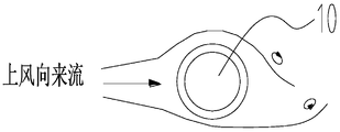
- Figure 6 is a schematic view of the tower tower shadow effect
- Figure 7 is a schematic diagram of the tower shadow effect produced by the tower
- Figure 8 is a top plan view of the top of the tower of Figure 4, showing the divided suction chamber
- Figure 9 is a schematic view showing the pressure sensing element provided in the pressure sensitive passage of Figure 5;
- Figure 10 is a side view of Figure 9;
- Figure 11 is an enlarged view of the pressure sensing element provided in Figure 10;
- Figure 12 is a schematic diagram showing the relationship between the Storocha number of the outer surface of the tower and the Reynolds number
- Figure 13 is a schematic view showing the temperature sensing element in the temperature sensing channel of Figure 9;
- Figure 14 is a graph showing the variation of the Nusselt number Nu and the angle of the partial surface of the tower under three Reynolds numbers Re when the air stream is swept away from the tower;
- Figure 15 is a control block diagram of the suction of the suction chamber of Figure 4.
- Figure 16 is a schematic view showing a vibration monitoring device inside the tower
- Figure 17 is a schematic view showing the comparison of the length of the suction through hole and the length of the blade in Figure 4;
- Figure 18 is a schematic view of the flow path of the exhaust gas stream of Figure 4 after it has risen to the top of the tower.
- 100 tower 100a suction through hole, 100b temperature sensing channel, 100c pressure sensing channel;
- FIG. 4 is a schematic structural view of a specific embodiment of a tower provided by the present invention
- FIG. 5 is a schematic exploded view of the upper portion of the tower provided with a suction through hole in FIG. Open the strip to facilitate the indication.
- the tower 100 is disposed above the tower foundation 600, and the top of the tower 100 is equipped with components such as a nacelle 200, a generator 300, an impeller 400, and the like.
- a plurality of suction through holes 100a penetrating through the inner and outer walls of the tower 100 are provided, and a plurality of suction through holes 100a are distributed along the circumferential direction of the tower 100. That is, it is distributed around the tower 100.
- a suction device is provided which is capable of suctioning the suction through hole 100a from the outside to the inside.
- the suction device can be placed inside the tower 100, of course, it can also be placed Externally.
- the suction through hole 100a is suctioned, since the suction through hole 100a penetrates the peripheral wall of the tower 100, the airflow at the outer surface of the tower 100 can be sucked.
- FIG. 6 is a schematic diagram of a tower tower shadow effect
- FIG. 7 is a schematic diagram of a tower shadow effect generated by a tower tube, and the lower part of the figure shows a dynamic change diagram when the blade 400a rotates clockwise, and the blade 400a is in three The position, in turn, forms a tapered flow path R1, a throat portion R2, and a diffusing flow path R3 as shown in the drawing with the outer surface of the tower 100.
- the blade 400a of the impeller 400 During the rotation of the blade 400a of the impeller 400, a "tower effect" occurs when passing through the tower 100.
- the inventors observed and measured that the upwind flow (multiphase flow) was driven away by the blade 400a in a rotating state.
- the blade 400a forms a tapered flow passage R1 structure with a compressed air flow before the tower 100 is directly in front of the tower 100; the narrowest flow passage is formed when passing through the front of the tower 100, that is, the throat shown in FIG. Part R2; the vane 400a is disposed directly in front of the tower 100 to form a diffuser flow passage R3.
- the blade 400a forms a variable cross-section fluid transport flow path in the field of engineering thermodynamics and engineering fluid dynamics before and after passing through the tower 100, that is, a zoom flow path (similar to a zoom nozzle structure), as shown in FIG. space.
- the airflow produces noise and thermodynamic irreversible energy losses during the flow of the scaled flow path.
- the process of compressing the upwind flow consumes the torque of the impeller 400, and periodically generates braking torque while generating ecologically damaging noise (the energy of the noise is also from the energy carried by the upwind flow).
- the pulsation is reduced as the corresponding blade 400a passes in front of the tower 100, and the pulsation is reduced along the wind direction.
- the blade 400a is transmitted to the blade root to cause pulsating load fatigue damage to the pitch bearing. This is the reason why the inventors discovered the problems caused by the background art, which have long existed in the field of wind power.
- the tower 100 is provided with a suction through hole 100a penetrating the peripheral wall thereof, and when the suction through hole 100a is sucked, when the blade 400a passes, the position of the tower 100 corresponding to the scaled flow path is due to The suction effect weakens the blocking effect of the tower 100.
- the rear of the blade 400a is similar to the infinite space when the blade 400a is rotated upward, that is, the outer wall of the tower 100 is practically impossible. Then, a zoom channel is formed with the blade 100a.
- the present scheme actually suppresses or eliminates the compression process (or compression work) when the airflow bypasses the tower 100, and at the same time increases the torque and the wheel power generated when the blade 400a passes in front of the tower 100, thereby improving
- the blade 400a converts the wind energy into a wind energy utilization coefficient of the rotary mechanical energy, and also reduces the pulsation of the blade 400a in the wind direction, and reduces the pulsation fatigue load on the pitch bearing.
- thermodynamic dissipation analysis and thermodynamic absorption utilization ie, irreversible dissipative process of converting compression, friction, energy into noise
- thermodynamic absorption utilization ie, irreversible dissipative process of converting compression, friction, energy into noise
- an angle measuring sensor is disposed on the bottom of the tower 100 or on the tower base 600, and three angle measuring sensors A, B, and C are shown, and the tip of the blade 400a can emit the laser 400b, and the angle is measured.
- Sensors A, B, C can sense the laser 400b to know if the blade 400a is entering the zoom space. In this way, the time at which the wind direction on the upstream surface of the tower 100 flows into the compressed state can be obtained, and in order to eliminate the compression phenomenon, the suction through hole 100a of the upstream surface of the tower 100 is opened. That is, the angle measuring sensor helps determine the timing at which the suction through hole 100a is sucked to eliminate the tower shadow effect, thereby effectively saving energy.
- the outer casing 701 is also provided in the tower 100, and the outer surface of the outer casing 701 and the tower 100 provided with the suction through hole 100a Form a closed suction chamber.
- the suction through hole 100a is provided in the upper portion of the tower 100, and accordingly, the outer casing 701 cooperates with the upper inner surface of the tower 100 to form an annular closed suction chamber.
- the suction device suctions the suction cavity to effect suction from the outer to the inner side of the suction through hole 100a.
- the closed suction chamber is provided, and the suction device can suck all the suction through holes 100a in the circumferential direction of the tower 100 as long as the annular suction chamber is sucked, and the suction is easier to realize.
- the suction device may have a plurality of suction ports 500a that cooperate with the suction through holes 100a, or one suction port 500a corresponding to the suction through holes 100a in a certain area. Wait.
- An air filtering section 703 may be provided between the suction chamber and the suction port 500a of the suction device. Specifically, as shown in FIG. 5, an annular air filter section 703 is provided at the bottom of the suction chamber, and the suction port 500a of the suction device is disposed below the annular air filter section 703, that is, at the bottom of the outer casing 701. .
- the air suction device sucks the external airflow inwardly, and the external airflow may carry sand dust, rain water, etc., and the air filter segment 703 can filter the airflow sucked in, so as not to damage the suction device, when the suction airflow is directed
- the cleanliness of the exhaust airflow can be improved, and the internal air can be prevented from being polluted, which is disadvantageous to the worker's operation or damage to the internal components of the tower 100.
- FIG. 5 is a top plan view of the top of the tower 100 of FIG. 4, showing the split suction chamber 704.
- the suction chamber is provided with a plurality of partitions 702 that divide the suction chamber into a plurality of circumferentially distributed suction chambers 704.
- the suction chamber is equally divided into eight suction chambers 704 through the partition plate 702 in the circumferential direction, and the upwind direction flows to the west, and the windward surface corresponds to the suction chambers numbered 1, 8 Room 704.
- the suction device draws the suction chambers 704 of the serial numbers 1, 8 and the remaining suction chambers 704 may not be aspirated.
- a plurality of suction chambers 704 are provided in Fig. 7, and the suction through holes 100a are shown on the windward side (the south side is just south, and the direction in which the blades 400a are located), and the remaining positions are not shown.
- the windward side can be determined according to the wind direction.
- a wind direction sensor may be provided to determine the number of the windward side and the corresponding suction chamber 704 based on the detected wind direction.
- FIG. 9 is a schematic view showing the pressure sensitive element 804 in the pressure sensitive passage 100c of the peripheral wall of the tower 100;
- FIG. 10 is a side view of FIG. 11 is an enlarged view of the pressure sensitive element 804 provided in FIG.
- the tower 100 may also be provided with a plurality of pressure sensitive elements 804 distributed along its circumferential direction for detecting the pressure at the outer surface of the tower 100.
- the tower shadow effect may cause pressure fluctuations, so according to the pressure detected by the pressure sensitive element 804, The orientation of the pressure fluctuation is obtained, which is the position of the upstream surface of the tower 100.
- the pressure sensitive element 804 can output the detected pressure signal to the controller, the controller determines the orientation of the upstream surface, and then controls the suction device to suction the suction chamber 704 corresponding to the upstream surface.
- a pressure sensitive passage 100c may be disposed on the peripheral wall of the tower 100.
- the pressure sensitive passage 100c also penetrates the peripheral wall of the tower 100, and the pressure sensitive element 804 is adjacent to the outer end of the outer surface of the tower 100 (the right end in FIG. 10).
- the pressure of the airflow at the outer surface of the tower 100 is sensed; the pressure sensitive element 804 is near the inner end of the inner surface of the tower 100 (the left end in FIG. 10), is the lead end 804a, and can output a signal to the controller.
- the pressure sensitive element 804 is also It can be a wireless output signal.
- the pressure sensing element 804 detects the pressure of the airflow on the outer surface of the tower 100 and facilitates the transmission of signals.
- the pressure sensing channel 100c can also provide a certain protection for the pressure sensing element 804.
- the pressure sensitive element 804 and the wind direction sensor can be mutually verified and redundant with each other.
- the positions of the upstream faces determined by the two are different, it is obvious that a sensor failure occurs, and the upstream surface can be determined according to the finally determined sensor that has not failed.
- the suction through hole 100a provided above can suppress the vortex induced vibration in addition to the suction to weaken or eliminate the adverse effect of the tower shadow effect.
- the boundary layer when the upwind flows around the flow tower 100, the boundary layer will form a periodic vortex shedding on both sides of the tower 100, that is, the phenomenon of the flow around the body, which is also the cause of the induced vortex induced vibration.
- the boundary layer can be "adsorbed" on the outer surface of the tower 100 by sucking from the plurality of suction through holes 100a, thereby suppressing or directly preventing the boundary layer from separating the outer surface of the tower 100, thereby reducing or The cause of the vortex-induced vibration is eliminated, and the purpose of suppressing the vortex-induced vibration is achieved.
- the suction through holes 100a are distributed in the circumferential direction, and the corresponding suction through holes 100a are available for suction regardless of the wind direction of the upwind direction.
- ⁇ (Re, St) is the frequency at which the vortex shedding, and ⁇ t as a whole is a variable; It is a Reynolds number and is a dimensionless number.
- ⁇ is the wind flow density on the tower 100
- U is the wind speed of the tower 100 on the wind direction
- C is the aerodynamic coefficient of the structural section of the tower 100;
- the aerodynamic coefficient is also called the wind carrier type coefficient, which is the ratio of the pressure (or suction) formed by the wind on the surface of the engineering structure to the theoretical wind pressure calculated according to the flow velocity. It reflects the distribution of stable wind pressure on the engineering structure and the surface of the building, and varies with the shape, dimensions, shielding conditions and airflow direction of the building;
- D and d which are characteristic scales of the spatial structure formed by the obstacle facing the fluid when the fluid passes through the obstacle and around the obstacle, are general terms in the field of heat transfer.
- it refers to the characteristic dimension of the enclosing structure (here, the outer surface shape of the tower) and the fluid contact surface (here, the air flow), and generally takes the width of the structure perpendicular to the wind direction, and the tower 100 is at the corresponding height.
- Outer diameter That is, the outer diameter of the tower 100 at the height of the distribution passage of the suction through hole 100a.
- ⁇ is the viscosity coefficient of the upwind flow.
- the lateral amplitude variation of the tower 100 structure caused by the vortex force is:
- K is the stiffness of the tower 100 structural system (which may include the nacelle 200);
- ⁇ is the logarithmic decay rate (about 0.05).
- the structure of the tower 100 may undergo vortex-induced resonance, and the amplitude of the vibration at this time is:
- the vortex-induced resonance amplitude can be reduced by the increase of the damping, such as reducing the aerodynamic coefficient C and reducing the upstream wind flow density ⁇ .
- the Strouhal number the definition of the Storocha number describes the relationship between the vortex shedding frequency, the wind speed, and the diameter of the cylinder.
- f is the vortex frequency, Hz
- U is the wind speed of the tower 100 on the wind direction
- D is the outer diameter of the tower 100 at the average height of the section of the suction through hole 100a.
- D in this embodiment refers to the outer diameter of the tower 100 at different heights.
- the path will change.
- the path around the periphery of the tower 100 forms an approximately elliptical shape, as described above for the aerodynamic shape.
- D is the equivalent diameter of the aeroelastic ellipse (heat transfer terminology, which is the diameter of an imaginary circular cross section, that is, the diameter of a non-circular cross section converted into a circular cross section according to the circumference).
- heat transfer terminology which is the diameter of an imaginary circular cross section, that is, the diameter of a non-circular cross section converted into a circular cross section according to the circumference.
- the Storocha number can be obtained according to the Reynolds number.
- the relationship with the Reynolds number can refer to Figure 12.
- Figure 12 is a schematic diagram of the relationship between the Storocha number and the Reynolds number on the outer surface of the tower.
- the horizontal axis is the Reynolds number and the vertical axis is the Toroha number.
- the Storocha number is a constant of 0.20.
- the Storocha number jumps to 0.30 first, then increases to 0.43, and then when the Reynolds number is equal to 2 ⁇ 10.
- the Stoloha number, D, and U are all available parameters, and f can also be calculated according to the formula of the Stollha number. Accordingly, the amplitude A can also be calculated.
- the tower 100 When the upwind flows around the flow tower 100, the tower 100 is provided with a position for sucking the through hole 100a based on the suction action, and the boundary layer airflow of the outer surface of the tower 100 is sucked into the tower 100 to maintain The boundary layer is in a laminar flow state, avoiding the boundary layer turning, so as to reduce the surface friction, so that the air flow flows to the outer surface of the tower 100, and the suction through hole 100a and the outer surface of the tower 100 smoothly transition, resulting in a relative tower
- the aerodynamic coefficient (C) of the flow around 100 becomes small, and according to the formula (3), the vortex-induced resonance amplitude (A) can be reduced, and the vortex-induced vibration can be suppressed.
- the outer casing 701 may be provided to form an annular suction chamber with the inner surface of the tower 100 for suction.
- the flow around the body is the formation of the Karman vortex street, which causes an important cause of the vortex-induced vibration, so that only the suction chamber 704 that sucks the flow-out direction can weaken or prevent the boundary layer from being detached.
- the occurrence of the Karman vortex street is suppressed, thereby suppressing or directly blocking the vortex-induced vibration.
- it is obviously only for the way of pumping around the flow direction, which is more targeted and can save energy, that is, to go upwind (more Directional absorption of phase flow).
- suction surface suction is also performed to weaken or eliminate the tower shadow effect, it is apparent that suction is required for both the flow-off surface and the flow-off direction on both sides of the upstream surface.
- Fig. 8 when the upwind flows around the flow tower 100, a flow around the tower 100 is generated.
- the upwind flow is the west, and the tower 100 is behind the tower 100, which is located substantially north of the north.
- the position of the east-south east (the direction from the tower 100 facing the windward direction, the counterclockwise or the instantaneous needle 110-130 degree angle), corresponding to the suction chamber of the serial number 3, 6 shown in Fig. 8. Room 704.
- the suction device suctions the suction chamber 704 corresponding to the direction of the outflow, and for Figure 8, it is substantially the two suction chambers 704 of the serial numbers 3, 6. Therefore, it is preferable to simultaneously suction the four suction chambers 704 having the numbers 1, 8, 3, and 6. In this way, both the adverse effects of the tower shadow effect are weakened or eliminated, and the vortex-induced vibration can be suppressed or eliminated.
- the suction device may have a plurality of suction ports 500a respectively corresponding to the plurality of suction chambers 704, and an on-off valve is provided between the suction port 500a and the corresponding suction chamber 704;
- the on-off valve can be an electric control valve 505.
- the controller can be set at the same time, and the controller can obtain the direction of the flow-off body and the direction of the flow surface, thereby controlling the electronic control corresponding to the direction of the flow-off body and the surface of the flow.
- the valve 505 is closed and the other electronically controlled valves 505 are controlled to be opened and closed for automatic control.
- manual control is also possible as a redundancy or alternative to electrical control.
- Each suction chamber 704 corresponds to a suction port 500a, and has a one-to-one correspondence, and the suction force of the suction device can be more ensured.
- the corresponding on-off valve is provided, only one set of suction device is needed.
- each suction chamber 704 it is also possible for each suction chamber 704 to correspond to a set of suction devices, but it is clear that a combination of a suction device and an on-off valve has a lower cost advantage.
- the suction manifold 504 may also be provided.
- the suction device specifically implements the suction function is the aspirator 501, pumping After the airflow in the suction chamber 704 passes through the suction port 500a, it is merged into the air extractor 501 through the suction manifold 504, facilitating the connection of the plurality of suction ports 500a and the air extractor 501, and also simplifying the pumping equipment. Suction line.
- FIG. 9 is a schematic diagram of the temperature sensing element in the temperature sensing channel of FIG. 9 .
- the tower 100 may also be provided with a plurality of temperature sensing elements 802 distributed along its circumferential direction for detecting the temperature of the boundary layer airflow at the outer surface of the tower 100 to obtain a flow around the body. Orientation. It can be seen from the above phenomenon that the flow around the body is out of the flow, the countercurrent flow occurs in the boundary layer, and a vortex is formed, so that the flow of the normal boundary layer is destroyed, and the heat transfer coefficient at the position is also the highest, so the temperature is also relatively low. By detecting the temperature of the entire circumferential direction of the tower 100, the relatively low temperature position is the direction of the flow around the body.
- a direction of the flow around the body can be determined according to the direction of the flow around the body and the direction of the upward wind flow. Specifically, it means that the upwind flow and the windward surface of the tower 100 form a stagnation point (the airflow stagnation point is a line from the top to the bottom of the tower 100), and the stagnation point and the tower 100 are winded on both sides of the wind direction.
- the flow-out body orientation forms an isosceles triangle at the horizontal plane, so that another flow-off body orientation is obtained by means of an isosceles triangle relationship.
- the temperature at the suction chamber 704 corresponding to the serial number 3 is low, and the temperature of the suction chamber 704 corresponding to the serial number 8 is actually high, which can be based on the serial number.
- 3 corresponding suction chamber 704 determines the direction of the flow around the body, and then determines the direction of the flow around the other side from the position of the upwind to the flow, that is, the same angle of counterclockwise to obtain the direction of the flow around the body Located at the suction chamber 704 corresponding to the serial number 6.
- the temperature sensing element 802 can output the detected temperature signal to the controller, the controller determines the direction of the flow around the body, and then controls the suction device to draw the corresponding suction chamber 704.
- a temperature sensing passage 100b may be disposed on the peripheral wall of the tower 100, and the temperature sensing passage 100b also penetrates the peripheral wall of the tower 100, and the temperature sensing element 802 is adjacent to the outer end of the outer surface of the tower 100 (the right end in FIG. 13).
- the temperature of the boundary layer at the outer surface of the tower 100 is sensed; the temperature sensing element 802 is near the inner end of the inner surface of the tower 100 (the left end in FIG. 13), is the lead end 802a, and can output a signal to the controller.
- the temperature sensing element 802 It can also be a wireless output signal.
- the temperature sensing element 802 can detect the temperature of the boundary layer airflow on the outer surface of the tower 100, and facilitate the transmission of the signal.
- the temperature sensing channel 100b can also provide a certain protection for the temperature sensing element 802. It can be understood that, based on the heat transfer, the outer surface heat exchange coefficient is high, the temperature is low, and the corresponding inner surface temperature is also low. Therefore, it is also possible that the temperature sensing element 802 is disposed inside the tower 100 to detect the inner surface temperature of the tower 100. . Of course, in comparison, the temperature sensing element 802 detects the boundary layer temperature of the outer surface to determine the most accurate direction of the flow around the body.
- a heat insulating layer 801 may be disposed between the temperature sensing element 802 and the inner wall of the temperature sensing channel 100b to avoid being affected by the peripheral wall of the tower 100.
- the temperature disturbance itself, only the temperature of the outer surface of the tower 100 is measured.
- the temperature sensing element 802 and the outer port of the temperature sensing channel 100b may have a predetermined distance, and the predetermined distance may be selected to be 15-25 mm, that is, the temperature is retracted within the temperature sensing channel 100b to make it accurately sense the boundary temperature of the outer surface. It is not affected by the radiation from the sun.
- the inner diameter of the temperature sensing passage 100b can be selected to be 9-11 mm.
- the measurement of the dry temperature sensing element 502 is avoided.
- an umbrella-like or mushroom-shaped covering object can be disposed at the outer port position of the temperature sensing passage 100b.
- the above provides a way to obtain the direction of the flow around the body according to the temperature detection.
- the direction of the flow around the body can also be obtained by the following method.
- FIG. 14 is a graph showing the variation of the Nusselt number Nu of the partial surface of the tower under the three Reynolds number Re when the air stream is swept away from the tower.
- the wind speed sensor and the wind direction sensor and the temperature sensor can be set (according to the physical quantity involved in the Reynolds number), the air flow temperature is measured to correct the viscosity coefficient of the air flow, the air flow density is corrected, the Reynolds number is obtained, and the reciprocating azimuth is obtained by the Reynolds number.
- the ordinate is Nusselt number Nu, dimensionless number, which indirectly reflects the surface heat transfer coefficient.
- the horizontal axis is the angle from the upwind direction to the tower wall contact surface normal vector clockwise to the right is defined as ⁇ / ( °), the three consecutive curves in the figure gradually increase from the bottom to the upper Reynolds number Re, the three peaks are about 110-125 °, and the corresponding increase is also increasing.
- the angle corresponding to the three "peaks” corresponds to the azimuth of the reverse flow gradient backflow, which has the highest heat exchange rate between the air flow and the outer wall of the tower.
- Figure 15 is a control block diagram for pumping the suction chamber of Figure 4;
- Figure 16 is a schematic view of the vibration monitoring device 803 disposed inside the tower 100.
- the method for determining the direction of the flow around the body can be performed simultaneously, thereby performing mutual verification and mutual redundancy. Under normal circumstances, the two directions of the flow around the body should be the same or substantially the same. If the deviation is large, the temperature sensing element 802 may be faulty, or the wind direction and the wind speed sensor may be faulty. When the faulty sensor is further determined, the actual bypass flow is determined according to the detection data of the fault sensor not generated. Orientation.
- the temperature signal of the temperature sensing element 802 in FIG. 15 is compared by the temperature sensing signal comparator. Obtaining the range of the flow around the body, obviously, it can also be judged after the controller receives the data, or the temperature signal comparator can be a unit module of the controller.
- the two directions of the face-to-face orientation can also be simultaneously performed, and the controller determines the actual heading surface position according to the wind direction detected by the wind direction sensor and the pressure fluctuation detected by the pressure sensitive element 804. .
- the controller According to the determined actual flow direction and the surface of the flow surface, the controller outputs a control signal, controls the air extractor 501 in the suction device to open, and closes the pumping corresponding to the flow direction and the flow surface.
- the electrically controlled valve 505 of the suction chamber 704 is closed for suction, while the electronically controlled valve 505 of the other suction chamber 704 is closed and closed.
- the opening number is 1, 3, 6, and 8.
- the electric control valve 505 corresponding to the suction chamber 704 closes the electric control valve 505 of the suction chamber 704 corresponding to 2, 4, 5, and 7.
- a vibration monitoring device 803 may be provided inside the tower 100 to detect the vibration of the tower 100 and output a vibration data signal (vibration amplitude, frequency, etc.) to the controller.
- the vibration monitoring device 803 may be provided on the inner surface of the tower 100, or may be, for example, inside the peripheral wall of the tower 100 or at other positions, and is easily disposed on the inner surface.
- the controller adjusts the air extractor 501 according to the feedback of the vibration monitoring device 803.
- the frequency and voltage of the motor that drives the air extractor 501 can be controlled to change the motor.
- the pressure and frequency conversion speed regulation realize the adjustment of the pumping flow of the air extractor 501.
- the power of the air extractor 501 is adjusted. For example, when the vibration is strong, the pumping flow rate can be increased, and when the vibration is reduced, the pumping flow rate can be reduced.
- the distribution density of the suction through hole 100a and the aperture of the suction through hole 100a itself also affect the effect of the pumping (the outer surface of the suction through hole 100a can smoothly transition into the hole), and the power of the air extractor 501 Adjustable, the setting of the suction through hole 100a is more flexible.
- the suction through holes 100a may be aligned along the circumference of the tower 100 and may be arranged in a fork.
- the vibration state information obtained by the vibration monitoring device 803 can be transmitted to the ground infinitely, so that the on-site commander can grasp and Carry out safe lifting crane operation.
- the pressure signal detected can also assist in determining the change in the tower shadow effect after pumping.
- the pressure fluctuation becomes smaller or disappears, the suction effect is obviously achieved; if the pressure still has large fluctuations, the pumping flow rate can be adjusted accordingly until the pressure fluctuation is significantly reduced or disappeared.
- the rotational speed of the impeller 400, the current wind speed (detectable by the wind speed sensor), and the opening frequency of the electric control valve 505 the opening frequency is determined by the direction of the upward wind direction
- the opening degree the opening degree is affected by the upward direction
- the change in the magnitude of the wind speed determines that the wind speed is greater and the opening degree is greater, and the controller can control accordingly.
- the controller can adjust the opening degrees of the air extractor 501 and the electric control valve 505 according to the signals of the pressure sensitive element 804 and the vibration monitoring device 803.
- the upward wind flows into the flow tower 100 and is divided into different passages, one is a passage having the suction through hole 100a, and the Reynolds number is artificially increased greatly.
- the upwind flow is accelerated at such a passage, and it is close to the outer surface of the tower 100, and no boundary layer separation and vortex phenomenon occur, which hinders the formation of vortex on the upper rear side of the tower 100;
- the section of the tower 100 of the hole 100a has no suction assistance, the Reynolds number is not changed, and the flow velocity is low.
- the manner in which the partial height section is provided with the suction through hole 100a completely disturbs the situation in which the frequency of the upper vortex shedding and the lower vortex shedding of the tower 100 in the prior art is uniform, thereby weakening their mutual action.
- the vortex-induced resonance response of the outer boundary layer of the tower 100 is reduced or prevented, and the vortex-induced vibration of the upper portion of the tower 100 is suppressed or directly prevented.
- Correlation is an important feature of the pulsating wind, where it is related to the pulsating wind speed at two points in space or the pulsating pressure at two points on the surface of the tower 100 at different heights.
- the correlation coefficient ⁇ is defined as
- the covariance is the time average of the product of the pulsating wind speed at two altitudes.
- Each wind speed value on the right side of the equation is subtracted from the respective average with
- u(t) is the turbulent component of the downwind direction, that is, the pulsating wind speed component in the direction of the average wind speed.
- the numerator indicates that the tower 100 has different wind speeds at two different heights, and the covariance of the pulsating wind speed.
- the covariance is the time average of the product of the pulsating wind speed at two altitudes.
- the overall intensity of turbulence can be measured by the standard deviation of the wind speed or the root mean square.
- the average component is subtracted from the wind speed, and then the remainder is quantified by the deviation. After the square is deviated, the average is averaged, and finally, the wind speed unit is obtained. Physical quantity, standard deviation is obtained.
- the correlation coefficient is defined by the correlation coefficient.
- the covariance of the wind speed at different heights is divided by the standard deviation to obtain the correlation coefficient between the two wind speeds at different heights. The smaller the correlation, the better, hindering the frequency of the vortex at different heights after the vortex is formed, breaking the frequency. Consistency aggregates and grows vortex-induced resonance energy, ie, prevents the growth of vortex-induced resonance, and even causes vortex-induced resonance to disappear.
- ⁇ (y i -y j ) is the correlation coefficient of the pulsating wind force per paragraph.
- the peripheral wall of the tower 100 is provided with a section having the suction through hole 100a and a section where the suction through hole 100a is not provided, thereby breaking the correlation between the upper and lower sides, and weakening or eliminating the vortex vibration.
- the vortex force distribution of the fluid-solid coupling along the outer surface of the tower 100 in the height direction is uneven, and the vortex energy is concentrated in the upper portion of the tower 100. Therefore, only the suction through hole 100a is provided in the upper portion of the tower 100. It can reduce the damage caused by vibration more specifically, and can also achieve the damage of the correlation between upper and lower.
- Fig. 17 is a schematic view showing the comparison of the length of the region of the suction through hole 100a and the length of the blade 400a in Fig. 4.
- the region where the suction through hole 100a is provided preferably covers the length region of the blade 400a of the blade 400a.
- the bottom of the region of the suction through hole 100a is equal to or slightly lower than the lowest point of the blade 400a, and the top portion is not extended to the top edge based on the top limit of the tower 100, specifically, the length of the blade 400a is L, and the suction through hole 100a
- the height of the area is approximately 0.6L.
- the exhaust port 500b of the suction device may be located at the bottom of the tower 100, as will be understood in conjunction with FIG. 18, which is the airflow after the exhaust airflow in FIG. 4 rises to the top of the tower 100. Schematic diagram of the path.
- the airflow discharged from the exhaust port 500b will continue to collect in a large amount at the bottom of the tower 100, thereby generating a positive pressure, forming a positive pressure airflow, and the tower 100, the tower 100 bottom air (electrical equipment, such as high-power converter, hot air flow generated by transformer) is pushed up, and the pushing action makes the hot air flow inside the tower 100 (the wind power equipment carries the high-power transformer inside the tower 100, each The electrical equipment generates electrical energy loss during operation. These losses are converted into heat energy to the internal environment of the tower, heating the air inside the tower 100 to form hot air.
- electrical equipment such as high-power converter, hot air flow generated by transformer
- the overall upward acceleration motion (the hot air flow is subject to its own lifting force and platoon)
- the combined action of the exhaust port 500b and the chimney effect enters the hub through the nacelle 200 or the generator 300 at the top of the tower 100, forming a positive pressure inside the hub, and passing through the pitch servo motor 901 and the pitch servo system.
- the surface of the control cabinet 903 generates convective heat transfer and produces a cooling effect.
- the heat exchanged gas carries heat from the root of the impeller 400, and in the extrusion process, it will prevent the rain or sand carried by the upwind from entering the shroud 902 (or the hub). It is equivalent to a sealed inner environment with a sealing function and a good enclosure.
- the speed can reach about 0.5m/s, and can be increased to 1m/s in the dusty airflow, which is enough to play the aforementioned blocking effect without affecting the upwind flow.
- the circumferential force generated by the impeller 400 is a sealed inner environment with a sealing function and a good enclosure.
- an exhaust manifold 503 may be provided, and the exhaust manifold 503 is annularly disposed, and a plurality of circumferentially uniformly distributed outlets 500b may be provided.
- the exhaust gas is uniformly exhausted over a wider range, and a transport line 502 is formed between the air extractor 501 and the exhaust manifold 500b. As shown in FIG. 4, the exhausted airflow collects at the bottom of the tower 100 and then rises upward and is squeezed out to form a path K.
- the exhausted airflow itself is the gas sucked from the suction chamber, that is, the air outside the tower 100 sucked into the suction through hole 100a, which is the air flow at the natural ambient temperature, at the bottom of the tower 100
- the heat generating equipment and components inside the tower 100 function as heat exchange cooling, which is equivalent to introducing an external “cold source” for cooling and cooling inside the tower 100, and The internal hot air is extruded.
- thermodynamics ie, the condition of low-quality energy conversion to high-quality energy and the way to improve.
- the process of passive work of impeller rotation is the second law of thermodynamics.
- the guiding principle of energy loss plays a role in the solution of this embodiment.
- the present embodiment can not only weaken or eliminate the tower shadow effect, prevent vortex-induced vibration induced by the boundary layer being detached, but also introduce outside air.
- the cold source performs heat exchange to cool down.
- the airflow sucked by the suction device may not be discharged into the inside of the tower 100 and may be discharged to the outside; or, it may be arranged that the exhaust port 500b can be discharged to the outside of the tower 100 or discharged to the inside, so that When the outside air flow has a high temperature and cannot produce a cooling effect, it can be selectively discharged to the outside.
- the formation of the positive pressure gas stream acts as a plugging action for the discharge and formation of the hot gas stream inside the tower 100, which is also a consideration in selecting the discharge to the outside or inside.
- the suction device may also be equipped with a dehumidifier to dehumidify the gas sucked from the suction through hole 100a, that is, to obtain a dry air flow, which may be inside the tower 100 or extruded from the top of the tower 100, or Avoid damage to other electrical components.
- a dehumidifier to dehumidify the gas sucked from the suction through hole 100a, that is, to obtain a dry air flow, which may be inside the tower 100 or extruded from the top of the tower 100, or Avoid damage to other electrical components.
- the dehumidifier can be bypassed, that is, the gas sucked from the suction through hole 100a can be dehumidified by the dehumidifier during the discharge process, and can be directly discharged from the dehumidifier in the dry season or in a dry environment. .
- the tower 100 and method provided by the above embodiments can attenuate or eliminate the adverse effects of the tower shadow effect. Further, it is also possible to suppress the vortex-induced vibration, and it is apparent that the suction through hole 100a is suctioned to adsorb the boundary layer, thereby directly suppressing or preventing the cause of the vortex-induced vibration, compared to the spiral mode mentioned in the background art. Better vibration suppression effect; Moreover, the suction force can be adjusted at any time according to the vibration state, which has higher flexibility and does not require higher cost; in addition, compared with the background art In terms of the noise generated when the flow is in contact with the spiral, the suction of the suction through hole 100a can obviously reduce the noise and meet the requirements of ecological regulations.
- the suction method can always be exerted during the hoisting or operation of the unit. Its inhibition of vortex induced vibration.
- the suctioned airflow When the suctioned airflow is discharged to the inside, it can also function as heat exchange cooling, plugging, and the like as described above. Even if the suctioned airflow is not discharged from the bottom, it can play a certain function of cooling and blocking as long as it is discharged inward. However, when it is discharged from the bottom, the rising and pushing effect of the suction airflow makes the cooling and sealing effect better.
Landscapes
- Engineering & Computer Science (AREA)
- General Engineering & Computer Science (AREA)
- Mechanical Engineering (AREA)
- Sustainable Development (AREA)
- Sustainable Energy (AREA)
- Chemical & Material Sciences (AREA)
- Combustion & Propulsion (AREA)
- Life Sciences & Earth Sciences (AREA)
- Physics & Mathematics (AREA)
- Architecture (AREA)
- Fluid Mechanics (AREA)
- Acoustics & Sound (AREA)
- Aviation & Aerospace Engineering (AREA)
- Structural Engineering (AREA)
- Civil Engineering (AREA)
- Wind Motors (AREA)
Abstract
Description


Claims (26)
- 塔筒(100),其特征在于,所述塔筒(100)设有贯通其周壁内外的抽吸通孔(100a),所述抽吸通孔(100a)沿所述塔筒(100)的周向分布;所述塔筒(100)还设有抽吸设备,所述抽吸设备能够对所述抽吸通孔(100a)进行自外向内的抽吸。
- 如权利要求1所述的塔筒,其特征在于,所述塔筒(100)内设有外壳(701),所述外壳(701)与设有所述抽吸通孔(100a)区域的塔筒(100)内表面围合形成环形密闭的抽吸腔体;所述抽吸设备抽吸所述抽吸腔体,以实现对所述抽吸通孔(100a)进行自外向内的抽吸。
- 如权利要求2所述的塔筒,其特征在于,所述抽吸腔体内还设有隔板(702),所述隔板(702)将所述抽吸腔体分割为若干沿周向分布的抽吸腔室(704);还包括控制器,所述控制器控制所述抽吸设备对所述塔筒(100)迎风面处对应的所述抽吸腔室(704)进行抽吸。
- 如权利要求3所述的塔筒,其特征在于,还包括风向传感器,所述控制器根据所述风向传感器检测的风向,确定所述迎风面,继而确定所述迎风面所对应的所述抽吸腔室(704)。
- 如权利要求3所述的塔筒,其特征在于,上风向来流绕流塔筒(100)时形成绕流脱体,所述抽吸设备还抽吸绕流脱体方位所对应的抽吸腔室(704)。
- 如权利要求5所述的塔筒,其特征在于,所述塔筒(100)还设有若干沿其周向分布的感温元件(802)和/或感压元件(804);所述感温元件(802)用于检测所述塔筒(100)外表面处气流的边界层温度,所述控 制器根据所述边界层温度获取所述绕流脱体方位;所述感压元件(804)用于检测所述塔筒(100)外表面处的压力,所述控制器根据所述压力的变化确定所述迎风面。
- 如权利要求6所述的塔筒,其特征在于,所述塔筒(100)设有贯通其周壁的感温通道(100b)和/或感压通道(100c),所述感温元件(802)设于所述感温通道(100b)内,所述感压元件(804)设于所述感压通道(100c)内。
- 如权利要求7所述的塔筒,其特征在于,所述感温元件(802)与所述感温通道(100b)的内壁之间设有绝热层(801);且所述感温元件(802)与所述感温通道(100b)的外端口,具有预定距离,所述预定距离为15-25mm。
- 如权利要求3或5所述的塔筒,其特征在于,所述抽吸设备具有若干抽吸口(500a),分别对应于若干所述抽吸腔室(704),且所述抽吸口(500a)与对应所述抽吸腔室(704)之间设有开关阀;所述控制器控制所述抽吸设备抽吸对应的所述抽吸腔室(704)时,控制其余所述抽吸腔室(704)对应的所述开关阀关闭;所述抽吸设备包括抽吸汇流母管(504)和抽气机(501),各所述抽吸口(500a)通过所述抽吸汇流母管(504)连通所述抽气机(501)。
- 如权利要求9所述的塔筒,其特征在于,还包括风速传感器和风向传感器,以获取所述绕流脱体方位以及所述迎风面,所述开关阀为电控阀(505);所述塔筒(100)还设有若干沿其周向分布的感温元件(802)和/或感 压元件(804);所述感温元件(802)用于检测所述塔筒(100)外表面处的边界层温度,以获取所述绕流脱体方位;所述感压元件(804)用于检测所述塔筒(100)外表面处的压力,根据所述压力的变化获取所述迎风面;所述控制器根据所述感温元件(802)获得的绕流脱体方位,以及所述风速传感器、风向传感器获得的绕流脱体方位,确定实际的绕流脱体方位;所述控制器根据所述感压元件(804)获得的迎风面,以及根据所述风向传感器获得的迎风面,确定实际的迎风面;所述控制器控制抽吸设备开启,同时开启与实际的迎风面以及实际的绕流脱体方位对应的所述电控阀(505),关闭其余所述电控阀(505)。
- 如权利要求10所述的塔筒,其特征在于,仅在所述塔筒(100)的上部设置所述抽吸通孔(100a)。
- 如权利要求1-8、11任一项所述的塔筒,其特征在于,所述抽吸设备的排气口(500b)位于所述塔筒(100)内的底部。
- 如权利要求12所述的塔筒,其特征在于,所述抽吸设备包括环形的排气汇流母管(503),所述抽吸设备抽吸的气流经所述排气汇流母管(503)排出;或,所述抽吸腔体与所述抽吸设备的抽吸口(500a)之间设有空气过滤段(703);或,所述抽吸设备包括除湿机,以对从所述抽吸通孔(100a)处抽吸出的气流进行除湿。
- 如权利要求1所述的塔筒,其特征在于,所述抽吸设备能够对所述塔筒(100)至少迎风面处的所述抽吸通孔(100a)进行自外向内的抽吸。
- 如权利要求14所述的塔筒,其特征在于,设置所述抽吸通孔(100a)区域的底部等于或略低于所述塔筒(100)顶部叶片(400a)的最低点。
- 如权利要求14所述的塔筒,其特征在于,还设有角度测量传感器,以检测所述塔筒(100)顶部的叶片(400a)是否摆动至缩放空间;缩放空间为所述叶片(400a)经过所述塔筒(100)正前方时与所述塔筒(100)的外壁之间形成的空间。
- 抑制塔筒塔影效应的方法,其特征在于,沿所述塔筒(100)周向设置贯通其周壁内外的抽吸通孔(100a);对所述抽吸通孔(100a)进行自外向内的抽吸。
- 如权利要求17所述的抑制塔筒塔影效应的方法,其特征在于,对所述塔筒(100)迎风面处的所述抽吸通孔(100a)进行抽吸。
- 如权利要求18所述的抑制塔筒塔影效应的方法,其特征在于,检测所述塔筒(100)顶部的叶片(400a)是否摆动至缩放空间;缩放空间为所述叶片(400a)经过所述塔筒(100)正前方时与所述塔筒(100)的外壁之间形成的空间;所述叶片(400a)进入所述缩放空间时,对所述塔筒(100)迎风面处的所述抽吸通孔(100a)进行抽吸。
- 如权利要求18所述的抑制塔筒塔影效应的方法,其特征在于,上风向来流绕流塔筒(100)时形成绕流脱体,还抽吸绕流脱体方位所对应位置处的所述抽吸通孔(100a)。
- 如权利要求20所述的抑制塔筒塔影效应的方法,其特征在于,沿所述塔筒(100)周向检测其外表面处的边界层温度,以获取所述绕流脱体方位。
- 如权利要求21所述的抑制塔筒塔影效应的方法,其特征在于,检 测所述塔筒(100)所处环境的风速和风向,以获取所述绕流脱体方位,并与根据边界层温度获取的绕流脱体方位进行相互校验,确定实际的绕流脱体方位。
- 如权利要求18所述的抑制塔筒塔影效应的方法,其特征在于,沿所述塔筒(100)周向检测其外表面处的压力,根据所述压力的变化获取所述迎风面。
- 如权利要求23所述的抑制塔筒塔影效应的方法,其特征在于,检测所述塔筒(100)所处环境的风向,以获取所述迎风面,并与根据所述压力的变化获取的迎风面进行相互校验,确定实际的迎风面;且根据所述压力变化反馈塔影效应的消除情况。
- 如权利要求17-24任一项所述的抑制塔筒塔影效应的方法,其特征在于,将抽吸的气流排出至所述塔筒(100)内的底部,所述气流能够向上浮升并推举所述塔筒(100)内部气流,在所述塔筒(100)顶部的导流罩(902)或轮毂内形成正压,以形成密封环境。
- 风力发电设备,包括塔筒(100)和位于所述塔筒(100)顶部的机舱(200)、发电机(300)以及叶轮(400),其特征在于,所述塔筒(100)为权利要求1-16任一项所述的塔筒(100)。
Priority Applications (4)
| Application Number | Priority Date | Filing Date | Title |
|---|---|---|---|
| ES18788657T ES2981735T3 (es) | 2017-09-11 | 2018-03-19 | Aparato de generación de energía eólica, cilindro de torre y método para suprimir efecto de sombreado de torre del cilindro de torre |
| US16/094,880 US11415107B2 (en) | 2017-09-11 | 2018-03-19 | Wind power generation apparatus, tower and method for suppressing tower shadow effect of tower |
| EP18788657.7A EP3477100B1 (en) | 2017-09-11 | 2018-03-19 | Wind power generation apparatus, tower barrel, and method for suppressing tower shadow effect of tower barrel |
| AU2018250454A AU2018250454B2 (en) | 2017-09-11 | 2018-03-19 | Wind power generation apparatus, tower and method for suppressing tower shadow effect of tower |
Applications Claiming Priority (2)
| Application Number | Priority Date | Filing Date | Title |
|---|---|---|---|
| CN201710812909.0A CN107387335B (zh) | 2017-09-11 | 2017-09-11 | 风力发电设备、塔筒及抑制塔筒塔影效应的方法 |
| CN201710812909.0 | 2017-09-11 |
Publications (1)
| Publication Number | Publication Date |
|---|---|
| WO2019047501A1 true WO2019047501A1 (zh) | 2019-03-14 |
Family
ID=60352175
Family Applications (1)
| Application Number | Title | Priority Date | Filing Date |
|---|---|---|---|
| PCT/CN2018/079415 Ceased WO2019047501A1 (zh) | 2017-09-11 | 2018-03-19 | 风力发电设备、塔筒及抑制塔筒塔影效应的方法 |
Country Status (6)
| Country | Link |
|---|---|
| US (1) | US11415107B2 (zh) |
| EP (1) | EP3477100B1 (zh) |
| CN (1) | CN107387335B (zh) |
| AU (1) | AU2018250454B2 (zh) |
| ES (1) | ES2981735T3 (zh) |
| WO (1) | WO2019047501A1 (zh) |
Cited By (4)
| Publication number | Priority date | Publication date | Assignee | Title |
|---|---|---|---|---|
| CN113007030A (zh) * | 2019-12-19 | 2021-06-22 | 新疆金风科技股份有限公司 | 塔架、成型方法、风力发电机组以及防护罩 |
| RU2762884C1 (ru) * | 2021-03-10 | 2021-12-23 | Федеральное государственное бюджетное образовательное учреждение высшего образования «Казанский государственный энергетический университет» | Ветрогенератор |
| CN116084371A (zh) * | 2023-02-02 | 2023-05-09 | 中国电建集团贵阳勘测设计研究院有限公司 | 一种海上风电安装平台 |
| CN118049372A (zh) * | 2024-04-16 | 2024-05-17 | 珠海凌达压缩机有限公司 | 涡旋盘组件、泵体结构和压缩机 |
Families Citing this family (7)
| Publication number | Priority date | Publication date | Assignee | Title |
|---|---|---|---|---|
| CN107387335B (zh) | 2017-09-11 | 2018-10-23 | 北京金风科创风电设备有限公司 | 风力发电设备、塔筒及抑制塔筒塔影效应的方法 |
| CN107605666B (zh) | 2017-09-11 | 2019-01-11 | 北京金风科创风电设备有限公司 | 具有抑制涡激振动功能的围护结构及抑制涡激振动的方法 |
| CN109869289B (zh) * | 2017-12-05 | 2020-10-16 | 中车株洲电力机车研究所有限公司 | 用于高塔架塔筒的通风冷却性能配置方法、装置及塔筒 |
| CN112855442B (zh) * | 2021-01-18 | 2022-03-29 | 青岛绿色发展研究院有限公司 | 一种基于振动和倾角的风机对风优化方法及系统 |
| CN115268356B (zh) * | 2022-07-29 | 2023-09-22 | 江苏道达风电设备科技有限公司 | 一种风电筒型基础负压智能控制系统 |
| CN116295252B (zh) * | 2023-03-24 | 2025-08-29 | 吉林里程协合风力发电有限公司 | 一种风机塔筒基础加固沉降监测装置 |
| KR102913638B1 (ko) * | 2023-04-19 | 2026-01-15 | 한국수력원자력 주식회사 | 블레이드 타워 간섭 소음 저감 장치, 및 이를 구비한 풍력발전기 |
Citations (5)
| Publication number | Priority date | Publication date | Assignee | Title |
|---|---|---|---|---|
| US20060290140A1 (en) * | 2005-06-24 | 2006-12-28 | Fuji Jukogyo Kabushiki Kaisha | Horizontal axis wind turbine |
| CN106224181A (zh) * | 2016-08-26 | 2016-12-14 | 东莞理工学院 | 一种风力发电机 |
| CN106640554A (zh) * | 2016-12-12 | 2017-05-10 | 北京金风科创风电设备有限公司 | 风力发电机组散热系统、散热方法及风力发电机组 |
| CN107387335A (zh) * | 2017-09-11 | 2017-11-24 | 北京金风科创风电设备有限公司 | 风力发电设备、塔筒及抑制塔筒塔影效应的方法 |
| CN107605666A (zh) * | 2017-09-11 | 2018-01-19 | 北京金风科创风电设备有限公司 | 具有抑制涡激振动功能的围护结构及抑制涡激振动的方法 |
Family Cites Families (16)
| Publication number | Priority date | Publication date | Assignee | Title |
|---|---|---|---|---|
| ATE250721T1 (de) * | 1999-07-14 | 2003-10-15 | Aloys Wobben | Windenergieanlage mit einem geschlossenen kühlkreislauf |
| DE10233947A1 (de) * | 2002-07-25 | 2004-02-12 | Siemens Ag | Windkraftanlage |
| DE10301080A1 (de) | 2002-10-22 | 2004-05-13 | Siemens Ag | Windkraftanlage |
| FR2935762B1 (fr) * | 2008-09-09 | 2013-02-15 | Suez Environnement | Eolienne |
| US8047774B2 (en) * | 2008-09-11 | 2011-11-01 | General Electric Company | System for heating and cooling wind turbine components |
| GB2466478A (en) * | 2008-12-02 | 2010-06-30 | Aerovortex Mills Ltd | Suction generation device |
| EP2376778B1 (en) * | 2008-12-17 | 2017-02-08 | XEMC Darwind BV | Wind turbine comprising a cooling circuit |
| JP5511549B2 (ja) * | 2010-06-30 | 2014-06-04 | 三菱重工業株式会社 | 風力発電装置 |
| US20110142671A1 (en) * | 2010-12-01 | 2011-06-16 | General Electric Company | Wind turbine rotor blades with enhanced lightning protection system |
| US8128364B2 (en) * | 2010-12-07 | 2012-03-06 | General Electric Company | Wind turbine rotor blade with porous window and controllable cover member |
| US20110211952A1 (en) * | 2011-02-10 | 2011-09-01 | General Electric Company | Rotor blade for wind turbine |
| US9127648B2 (en) * | 2011-04-19 | 2015-09-08 | Gamesa Innovation & Technology, S.L. | System to cool the nacelle and the heat generating components of an offshore wind turbine |
| ES2484697T3 (es) * | 2011-09-09 | 2014-08-12 | Areva Wind Gmbh | Torre de turbina eólica con refuerzo de muro de torre de guía de aire circunferencial |
| CN202991359U (zh) * | 2012-08-07 | 2013-06-12 | 上海万德风力发电股份有限公司 | 永磁直驱风力发电机组用气流冷却系统 |
| TWI486523B (zh) * | 2012-11-30 | 2015-06-01 | Ind Tech Res Inst | 應用於一風力發電機之輪轂冷卻裝置 |
| US10000277B2 (en) * | 2014-10-16 | 2018-06-19 | Rohr, Inc. | Perforated surface for suction-type laminar flow control |
-
2017
- 2017-09-11 CN CN201710812909.0A patent/CN107387335B/zh active Active
-
2018
- 2018-03-19 EP EP18788657.7A patent/EP3477100B1/en active Active
- 2018-03-19 US US16/094,880 patent/US11415107B2/en active Active
- 2018-03-19 ES ES18788657T patent/ES2981735T3/es active Active
- 2018-03-19 WO PCT/CN2018/079415 patent/WO2019047501A1/zh not_active Ceased
- 2018-03-19 AU AU2018250454A patent/AU2018250454B2/en active Active
Patent Citations (5)
| Publication number | Priority date | Publication date | Assignee | Title |
|---|---|---|---|---|
| US20060290140A1 (en) * | 2005-06-24 | 2006-12-28 | Fuji Jukogyo Kabushiki Kaisha | Horizontal axis wind turbine |
| CN106224181A (zh) * | 2016-08-26 | 2016-12-14 | 东莞理工学院 | 一种风力发电机 |
| CN106640554A (zh) * | 2016-12-12 | 2017-05-10 | 北京金风科创风电设备有限公司 | 风力发电机组散热系统、散热方法及风力发电机组 |
| CN107387335A (zh) * | 2017-09-11 | 2017-11-24 | 北京金风科创风电设备有限公司 | 风力发电设备、塔筒及抑制塔筒塔影效应的方法 |
| CN107605666A (zh) * | 2017-09-11 | 2018-01-19 | 北京金风科创风电设备有限公司 | 具有抑制涡激振动功能的围护结构及抑制涡激振动的方法 |
Non-Patent Citations (1)
| Title |
|---|
| See also references of EP3477100A4 * |
Cited By (5)
| Publication number | Priority date | Publication date | Assignee | Title |
|---|---|---|---|---|
| CN113007030A (zh) * | 2019-12-19 | 2021-06-22 | 新疆金风科技股份有限公司 | 塔架、成型方法、风力发电机组以及防护罩 |
| RU2762884C1 (ru) * | 2021-03-10 | 2021-12-23 | Федеральное государственное бюджетное образовательное учреждение высшего образования «Казанский государственный энергетический университет» | Ветрогенератор |
| CN116084371A (zh) * | 2023-02-02 | 2023-05-09 | 中国电建集团贵阳勘测设计研究院有限公司 | 一种海上风电安装平台 |
| CN116084371B (zh) * | 2023-02-02 | 2024-05-24 | 中国电建集团贵阳勘测设计研究院有限公司 | 一种海上风电安装平台 |
| CN118049372A (zh) * | 2024-04-16 | 2024-05-17 | 珠海凌达压缩机有限公司 | 涡旋盘组件、泵体结构和压缩机 |
Also Published As
| Publication number | Publication date |
|---|---|
| EP3477100C0 (en) | 2024-06-12 |
| EP3477100B1 (en) | 2024-06-12 |
| CN107387335A (zh) | 2017-11-24 |
| EP3477100A4 (en) | 2019-08-28 |
| AU2018250454B2 (en) | 2020-02-27 |
| ES2981735T3 (es) | 2024-10-10 |
| EP3477100A1 (en) | 2019-05-01 |
| AU2018250454A1 (en) | 2019-03-28 |
| US11415107B2 (en) | 2022-08-16 |
| US20210231106A1 (en) | 2021-07-29 |
| CN107387335B (zh) | 2018-10-23 |
Similar Documents
| Publication | Publication Date | Title |
|---|---|---|
| CN107387335B (zh) | 风力发电设备、塔筒及抑制塔筒塔影效应的方法 | |
| WO2019047484A1 (zh) | 具有抑制涡激振动功能的围护结构及抑制涡激振动的方法 | |
| ES2796113T3 (es) | Aparato de cuerpo flotante para suprimir la vibración del cuerpo de torre | |
| CN102325989B (zh) | 用于风能转换系统的涡轮机进口塔 | |
| WO2019047537A1 (zh) | 外表面具有抑制涡激振动功能的围护结构 | |
| CN110630446B (zh) | 围护结构以及风力发电机组、塔筒结构 | |
| WO2019242179A1 (zh) | 围护结构以及设于围护结构外表面的气动外形调整器 | |
| CN107461303B (zh) | 抑制围护结构振动的方法、设备以及塔筒的吊装方法 | |
| CN107740752A (zh) | 抑制围护结构振动的环绕体设备和方法 | |
| AU2018264071B2 (en) | Streamlined body and streamlined apparatus for suppressing vibrations of enclosure and method for hoisting tower | |
| CN108843516B (zh) | 外表面设有减阻器的围护结构 | |
| CN107461304A (zh) | 抑制围护结构振动的环绕体、设备、吊装塔筒的方法 |
Legal Events
| Date | Code | Title | Description |
|---|---|---|---|
| WWE | Wipo information: entry into national phase |
Ref document number: 2018788657 Country of ref document: EP |
|
| ENP | Entry into the national phase |
Ref document number: 2018788657 Country of ref document: EP Effective date: 20181109 |
|
| ENP | Entry into the national phase |
Ref document number: 2018788657 Country of ref document: EP Effective date: 20181119 |
|
| ENP | Entry into the national phase |
Ref document number: 2018250454 Country of ref document: AU Date of ref document: 20180319 Kind code of ref document: A |
|
| NENP | Non-entry into the national phase |
Ref country code: DE |