WO2019049321A1 - 電力変換装置 - Google Patents
電力変換装置 Download PDFInfo
- Publication number
- WO2019049321A1 WO2019049321A1 PCT/JP2017/032514 JP2017032514W WO2019049321A1 WO 2019049321 A1 WO2019049321 A1 WO 2019049321A1 JP 2017032514 W JP2017032514 W JP 2017032514W WO 2019049321 A1 WO2019049321 A1 WO 2019049321A1
- Authority
- WO
- WIPO (PCT)
- Prior art keywords
- phase
- voltage
- axis current
- switch
- converter
- Prior art date
- Legal status (The legal status is an assumption and is not a legal conclusion. Google has not performed a legal analysis and makes no representation as to the accuracy of the status listed.)
- Ceased
Links
Images


Classifications
-
- H—ELECTRICITY
- H02—GENERATION; CONVERSION OR DISTRIBUTION OF ELECTRIC POWER
- H02P—CONTROL OR REGULATION OF ELECTRIC MOTORS, ELECTRIC GENERATORS OR DYNAMO-ELECTRIC CONVERTERS; CONTROLLING TRANSFORMERS, REACTORS OR CHOKE COILS
- H02P21/00—Arrangements or methods for the control of electric machines by vector control, e.g. by control of field orientation
- H02P21/14—Estimation or adaptation of machine parameters, e.g. flux, current or voltage
-
- H—ELECTRICITY
- H02—GENERATION; CONVERSION OR DISTRIBUTION OF ELECTRIC POWER
- H02M—APPARATUS FOR CONVERSION BETWEEN AC AND AC, BETWEEN AC AND DC, OR BETWEEN DC AND DC, AND FOR USE WITH MAINS OR SIMILAR POWER SUPPLY SYSTEMS; CONVERSION OF DC OR AC INPUT POWER INTO SURGE OUTPUT POWER; CONTROL OR REGULATION THEREOF
- H02M5/00—Conversion of AC power input into AC power output, e.g. for change of voltage, for change of frequency, for change of number of phases
- H02M5/40—Conversion of AC power input into AC power output, e.g. for change of voltage, for change of frequency, for change of number of phases with intermediate conversion into DC
- H02M5/42—Conversion of AC power input into AC power output, e.g. for change of voltage, for change of frequency, for change of number of phases with intermediate conversion into DC by static converters
- H02M5/44—Conversion of AC power input into AC power output, e.g. for change of voltage, for change of frequency, for change of number of phases with intermediate conversion into DC by static converters using discharge tubes or semiconductor devices to convert the intermediate DC into AC
- H02M5/453—Conversion of AC power input into AC power output, e.g. for change of voltage, for change of frequency, for change of number of phases with intermediate conversion into DC by static converters using discharge tubes or semiconductor devices to convert the intermediate DC into AC using devices of a triode or transistor type requiring continuous application of a control signal
- H02M5/458—Conversion of AC power input into AC power output, e.g. for change of voltage, for change of frequency, for change of number of phases with intermediate conversion into DC by static converters using discharge tubes or semiconductor devices to convert the intermediate DC into AC using devices of a triode or transistor type requiring continuous application of a control signal using semiconductor devices only
- H02M5/4585—Conversion of AC power input into AC power output, e.g. for change of voltage, for change of frequency, for change of number of phases with intermediate conversion into DC by static converters using discharge tubes or semiconductor devices to convert the intermediate DC into AC using devices of a triode or transistor type requiring continuous application of a control signal using semiconductor devices only having a rectifier with controlled elements
-
- H—ELECTRICITY
- H02—GENERATION; CONVERSION OR DISTRIBUTION OF ELECTRIC POWER
- H02M—APPARATUS FOR CONVERSION BETWEEN AC AND AC, BETWEEN AC AND DC, OR BETWEEN DC AND DC, AND FOR USE WITH MAINS OR SIMILAR POWER SUPPLY SYSTEMS; CONVERSION OF DC OR AC INPUT POWER INTO SURGE OUTPUT POWER; CONTROL OR REGULATION THEREOF
- H02M7/00—Conversion of AC power input into DC power output; Conversion of DC power input into AC power output
- H02M7/42—Conversion of DC power input into AC power output without possibility of reversal
- H02M7/44—Conversion of DC power input into AC power output without possibility of reversal by static converters
- H02M7/48—Conversion of DC power input into AC power output without possibility of reversal by static converters using discharge tubes with control electrode or semiconductor devices with control electrode
- H02M7/53—Conversion of DC power input into AC power output without possibility of reversal by static converters using discharge tubes with control electrode or semiconductor devices with control electrode using devices of a triode or transistor type requiring continuous application of a control signal
- H02M7/537—Conversion of DC power input into AC power output without possibility of reversal by static converters using discharge tubes with control electrode or semiconductor devices with control electrode using devices of a triode or transistor type requiring continuous application of a control signal using semiconductor devices only, e.g. single switched pulse inverters
- H02M7/539—Conversion of DC power input into AC power output without possibility of reversal by static converters using discharge tubes with control electrode or semiconductor devices with control electrode using devices of a triode or transistor type requiring continuous application of a control signal using semiconductor devices only, e.g. single switched pulse inverters with automatic control of output wave form or frequency
- H02M7/5395—Conversion of DC power input into AC power output without possibility of reversal by static converters using discharge tubes with control electrode or semiconductor devices with control electrode using devices of a triode or transistor type requiring continuous application of a control signal using semiconductor devices only, e.g. single switched pulse inverters with automatic control of output wave form or frequency by pulse-width modulation
-
- H—ELECTRICITY
- H02—GENERATION; CONVERSION OR DISTRIBUTION OF ELECTRIC POWER
- H02P—CONTROL OR REGULATION OF ELECTRIC MOTORS, ELECTRIC GENERATORS OR DYNAMO-ELECTRIC CONVERTERS; CONTROLLING TRANSFORMERS, REACTORS OR CHOKE COILS
- H02P21/00—Arrangements or methods for the control of electric machines by vector control, e.g. by control of field orientation
- H02P21/0003—Control strategies in general, e.g. linear type, e.g. P, PI, PID, using robust control
-
- H—ELECTRICITY
- H02—GENERATION; CONVERSION OR DISTRIBUTION OF ELECTRIC POWER
- H02P—CONTROL OR REGULATION OF ELECTRIC MOTORS, ELECTRIC GENERATORS OR DYNAMO-ELECTRIC CONVERTERS; CONTROLLING TRANSFORMERS, REACTORS OR CHOKE COILS
- H02P21/00—Arrangements or methods for the control of electric machines by vector control, e.g. by control of field orientation
- H02P21/06—Rotor flux based control involving the use of rotor position or rotor speed sensors
-
- H—ELECTRICITY
- H02—GENERATION; CONVERSION OR DISTRIBUTION OF ELECTRIC POWER
- H02P—CONTROL OR REGULATION OF ELECTRIC MOTORS, ELECTRIC GENERATORS OR DYNAMO-ELECTRIC CONVERTERS; CONTROLLING TRANSFORMERS, REACTORS OR CHOKE COILS
- H02P21/00—Arrangements or methods for the control of electric machines by vector control, e.g. by control of field orientation
- H02P21/22—Current control, e.g. using a current control loop
-
- H—ELECTRICITY
- H02—GENERATION; CONVERSION OR DISTRIBUTION OF ELECTRIC POWER
- H02P—CONTROL OR REGULATION OF ELECTRIC MOTORS, ELECTRIC GENERATORS OR DYNAMO-ELECTRIC CONVERTERS; CONTROLLING TRANSFORMERS, REACTORS OR CHOKE COILS
- H02P25/00—Arrangements or methods for the control of AC motors characterised by the kind of AC motor or by structural details
- H02P25/02—Arrangements or methods for the control of AC motors characterised by the kind of AC motor or by structural details characterised by the kind of motor
- H02P25/022—Synchronous motors
- H02P25/024—Synchronous motors controlled by supply frequency
-
- H—ELECTRICITY
- H02—GENERATION; CONVERSION OR DISTRIBUTION OF ELECTRIC POWER
- H02P—CONTROL OR REGULATION OF ELECTRIC MOTORS, ELECTRIC GENERATORS OR DYNAMO-ELECTRIC CONVERTERS; CONTROLLING TRANSFORMERS, REACTORS OR CHOKE COILS
- H02P27/00—Arrangements or methods for the control of AC motors characterised by the kind of supply voltage
- H02P27/04—Arrangements or methods for the control of AC motors characterised by the kind of supply voltage using variable-frequency supply voltage, e.g. inverter or converter supply voltage
- H02P27/06—Arrangements or methods for the control of AC motors characterised by the kind of supply voltage using variable-frequency supply voltage, e.g. inverter or converter supply voltage using DC to AC converters or inverters
- H02P27/08—Arrangements or methods for the control of AC motors characterised by the kind of supply voltage using variable-frequency supply voltage, e.g. inverter or converter supply voltage using DC to AC converters or inverters with pulse width modulation
Definitions
- the present invention relates to a power conversion device, and more particularly to a power conversion device provided with both a synchronous input function and a reactive power control function.
- Patent Document 1 performs synchronization simultaneously using the speed reference of an AC motor as a trigger signal, but performs synchronization simultaneously and drives from an inverter device to driving by a commercial AC power supply. After switching, there is a problem that the inverter device is not utilized at all. This problem also applies to Patent Document 2 and Patent Document 3.
- the present invention has been made in view of the above-mentioned problems, and a power conversion apparatus that effectively uses the inverter device even after switching from driving by the inverter device to driving by a commercial AC power supply by performing synchronization in parallel Intended to provide.
- the power conversion device of the present invention is connected to a converter that receives a three-phase AC power supply and outputs a DC voltage, and is connected to the output of the converter to drive an AC motor via an output switch.
- a power switch for directly driving the AC motor with the AC power
- a first current detector for detecting the output current of the inverter, and a voltage and current of a power system on the input side of the converter
- a control unit for controlling the three-phase output voltage of the inverter based on the first three-phase voltage command, the control unit detecting the voltage detector and the second current detector respectively detecting Is
- a speed controller that outputs a first Q-axis current reference by controlling so as to minimize deviation between a given speed reference and a directly or indirectly obtained speed feedback of the AC motor; and the first current
- a first three-phase to two-phase converter for converting a three-phase current detected by a detector into a first Q-axis current feedback and a first D-axis current feedback based on a first reference
- the present invention it is possible to provide a power conversion device that makes effective use of the inverter device after switching from driving by the inverter device to driving by a commercial AC power supply by performing synchronization simultaneously.
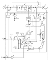
- FIG. 1 is a circuit diagram of a power converter according to a first embodiment of the present invention.
- Commercial three-phase AC power supply 1 is connected to the AC power supply side of input switch 2 via current detector 13. Further, the power converter side of the input switch 2 is connected to the diode converter 31 of the power converter 3.
- the power converter 3 includes a diode converter 31, a DC capacitor 33 and an inverter 32.
- the DC output of the diode converter 31 is smoothed by the DC capacitor 33 and input to the inverter 32.
- the AC output of the inverter 32 drives the AC motor 5 via the current detector 12 and further via the output switch 4.
- a switch 6 is provided so that the AC motor 5 can be driven directly from the AC power supply 1. That is, the AC power supply side of the switch 6 is connected to the AC power supply side of the input switch 2, and the AC motor side of the switch 6 is connected to the AC motor side of the output switch 4.
- the inverter 32 is a voltage type PWM converter.
- the power devices constituting the inverter 32 are on / off controlled by a gate signal supplied from the control unit 7.
- the speed detector 11 is attached to the AC motor 5, and the output is given to the control unit 7.
- a current detector 12 is provided on the output side of the inverter 32 and this output is also given to the control unit 7.
- a voltage detector 14 is provided on the AC power supply side of the input switch 2. The outputs of the current detector 13 and the voltage detector 14 are also given to the control unit 7.
- the internal configuration of the control unit 7 will be described.
- the case where the AC motor 5 is driven at variable speeds in a state where the switch 6 is turned off and the input switch 2 and the output switch 4 are turned on will be described.
- the operation signal S6 of the switch 6 is operated by the synchronization and entry controller 83 described later.
- the case where the AC motor 5 is driven at variable speed is referred to as a motor drive mode.
- An externally applied speed reference is connected to the first input of the adder / subtractor 71.
- a speed fine adjustment signal ⁇ s which is an output of the synchronization / accumulation controller 83 described later, is input.
- the period during which the AC motor 5 is activated to drive at a variable speed is set such that the speed fine adjustment signal ⁇ s, which is the output of the synchronous combination controller 83, becomes zero.
- the velocity feedback obtained by the velocity detector 11 is connected to the third input of the adder / subtractor 71.
- the adder / subtractor 71 calculates the difference of the third input from the sum of the first input and the second input, and is applied to the speed controller 72.
- the speed controller 72 is, for example, a PI controller. Then, the speed controller 72 performs adjustment control so as to minimize the given difference and outputs a torque reference.
- the torque reference is divided by the magnetic flux reference set separately by the divider 73 to be a torque current reference. This torque current reference is connected to the first input of the switch 74A. Further, 0 is inputted to the second input of the switch 74A. The output of the switch 74A is connected to the subtractor 75A.
- the switching signal S74A of the switching device 74A is operated by the synchronization and entry controller 83 described later.
- the switching signal S74A of the switch 74A is set so that the output of the switch 74A selects the first input during the period of the motor drive mode in which the AC motor 5 is activated to drive at variable speed.
- the torque current reference is applied to the first input of the subtractor 75A via the switch 74A.
- the flux current reference is obtained by providing the flux reference to the flux current converter 73A.
- a flux current reference which is an output of the flux current converter 73A is connected to a first input of the switch 74B.
- the output of a reactive power controller 87 described later is connected to the second input of the switch 74B.
- the output of switch 74B is connected to the first input of adder-subtractor 75B.
- the switching signal S74B of the switching device 74B is operated by the synchronization and entry controller 83 described later.
- the switching signal S74B of the switch 74B is set such that the output of the switch 74B selects the first input. Therefore, during this period, the magnetic flux current reference is given to the adder / subtractor 75B via the switch 74B.
- the voltage fine adjustment signal ⁇ v which is an output of the synchronization / accumulation controller 83 described later, is input to the second input of the adder / subtractor 75B. Further, the period of the motor drive mode is set such that the voltage fine adjustment signal ⁇ v, which is the output of the synchronization and entry controller 83, becomes zero.
- the three-phase output current detected by the current detector 12 is given to a three-phase to two-phase converter 79.
- the three-phase to two-phase converter 79 converts the three-phase current into two-axis DC components orthogonal to each other at a reference phase ⁇ which is an output of a switch 74C described later.
- the current components of the two axes can be made into a Q-axis current feedback as torque current feedback and a D-axis current feedback as flux current feedback orthogonal thereto.
- the Q-axis current feedback is provided as the subtraction input of the subtractor 75A, and the difference from the first input of the subtractor 75A is provided to the Q-axis current controller 76A.
- the D-axis current feedback is given as the third input of the adder-subtractor 75B, and the difference between the sum of the first and second inputs of the adder-subtractor 75B and the third input is given to the D-axis current controller 76B.
- the Q-axis current controller 76A and the D-axis current controller 76B are, for example, PI controllers.
- the Q-axis current controller 76A and the D-axis current controller 76B perform adjustment control so as to minimize their respective inputs and output the Q-axis voltage command and the D-axis voltage command, respectively.
- the two-phase to three-phase converter 77 converts the Q-axis voltage command and the D-axis voltage command into a three-phase voltage command using the reference phase ⁇ which is the output of the switch 74C, and outputs the output to the PWM controller 78.
- the PWM controller 78 supplies a PWM-modulated gate signal to each power device of the inverter 32 so that the output voltage of each phase of the inverter 32 becomes a voltage command of these three phases.
- the reference phase ⁇ will be described below. Assuming that the AC motor 5 is an induction motor, the slip s of the induction motor is determined by the slip calculator 80 from the above-described flux reference and the torque current reference which is the output of the divider 73. The slip s is added to the speed feedback by the adder 81 to obtain the output frequency of the inverter 32. The output frequency is integrated by the integrator 82 to obtain the reference phase ⁇ M of the input terminal voltage of the AC motor M. The reference phase ⁇ M which is the output of the integrator 87 is connected to the first input of the switch 74C.
- the output of the switch 74C is the reference phase ⁇ .
- the switching signal S74C of the switching device 74C is operated by the synchronization and entry controller 83 described later. During the motor drive mode, the switching signal S74C of the switch 74C is set such that the output of the switch 74C selects the first input.
- the reference phase ⁇ M of the input terminal voltage of the AC motor M becomes the reference phase ⁇ , and is supplied to the two-phase / three-phase converter 77 and the three-phase / two-phase converter 79 via the switch 74C.
- the configuration described above is composed of the configuration requirements for so-called vector control of the AC motor 5.
- the externally applied speed reference is set at a predetermined rate so as to increase from zero rotational speed to a rotational speed equivalent to when the AC motor 5 is directly driven by the AC power supply 1.
- the fundamental wave output frequency of the inverter 32 can be made the same frequency as the AC power supply 1.
- the phase of the voltage of the AC power supply 1 detected by the voltage detector 14 is detected by the PLL controller 84 to obtain a reference phase ⁇ S.
- the PLL controller 84 is a phase synchronization circuit using a phase locked loop, and outputs a reference phase ⁇ S synchronized with the voltage of the AC power supply 1.
- the reference phase ⁇ S is determined such that the voltage phase and the in-phase component of the AC power supply are q-axis and the component orthogonal thereto is the d-axis.
- the synchronous input controller 83 has, as a monitoring input, the voltage of the AC power supply 1 detected by the voltage detector 14 and a reference phase ⁇ S synchronized with the voltage of the AC power supply 1 which is the output of the PLL controller 84
- a reference phase ⁇ M of the three-phase voltage command which is the output of the phase-three phase converter 77 and the input terminal voltage of the AC motor M which is the output of the integrator 82 is input.
- the three-phase voltage command is a signal corresponding to the fundamental wave voltage output of the inverter 32.
- the synchronous combination controller 83 rises up to a rotational speed equivalent to when the AC motor 5 is directly driven by the AC power supply 1, and the frequency of the voltage of the AC power supply 1 detected by the voltage detector 14 and 2-phase to 3-phase conversion
- the difference between the frequencies of the three-phase voltage commands, which are the output of the inverter 77 falls within a predetermined range, the voltage, frequency and phase of the voltage of the AC power supply 1 and the fundamental wave of the output voltage of the inverter 32 coincide.
- Perform so-called uniform speed control is performed.
- the case where the uniform velocity control is performed is referred to as a uniform velocity mode.
- the frequency of the voltage of the AC power supply 1 detected by the voltage detector 14 and the output of the 2-phase to 3-phase converter 77 rise up to a rotational speed equivalent when the AC motor 5 is directly driven by the AC power supply 1.
- the motor drive mode is shifted to the uniform speed mode.
- the synchronization and alignment controller 83 outputs the speed fine adjustment signal ⁇ s and the second input of the adder / subtractor 71. Furthermore, the deviation of the voltage of the AC power supply 1 detected by the voltage detector 14 and the three-phase voltage command (corresponding to the fundamental wave of the output voltage of the inverter 32) which is the output of the two-phase to three-phase converter 77 A voltage fine adjustment signal ⁇ v for adjustment is output and given as a d-axis correction current to the second input of the subtractor 75B.
- the details of the uniform speed control function of the synchronization and entry controller 83 are described in, for example, Patent Document 2 and Patent Document 3, and thus the description thereof is omitted.
- the synchronization and entry controller 83 When the switch 6 is turned on, the inverter 32 performs parallel operation with the AC power supply 1. After turning on the switch 6, the synchronization and entry controller 83 generates a control switching signal to switch the operation of the power converter 3 from the all-speed operation mode to the reactive power control mode. That is, the synchronization input controller 83 changes the switching signal S74A, switches the output signal of the switch 74A from the first input to the second input, changes the switching signal S74B, and changes the output signal of the switch 74B from the first input. It switches to the second input, changes the switching signal S74C, switches the output signal of the switch 74C from the first input to the second input, and sets the outputs of the speed fine adjustment signal ⁇ s and the voltage fine adjustment signal ⁇ v to zero.
- the output of switch 74A goes from the output of divider 73 to 0, the output of switch 74B from the output of flux current converter 73A to the output of reactive power controller 87, and the output of switch 74C
- the outputs are each switched to the output of the PLL controller 84.
- the input switch 2 maintains the on state.
- the output of the switch 74A is 0 in the reactive power control mode.
- the output of the switch 74A corresponds to the torque current reference, and becomes the q-axis current reference in the q-axis current control loop of the inverter 32. Since the output voltage phase of the inverter 32 and the voltage phase of the AC power supply 1 are synchronized, the q-axis current component output from the inverter 32, that is, the active current component is zero.
- the reactive power controller 87 will be described.
- the output of the current detector 13 and the output of the voltage detector 14 are input to the ineffective detector 85, and the reactive power detector 85 detects reactive power passing through the current detector 13. That is, in the present embodiment, the total reactive power of the AC motor 5 and the power converter 3 is detected.
- the output of reactive power detector 85 is input to the subtraction terminal of subtractor 86.
- An externally set reactive power reference is input to the addition terminal of the subtractor 86.
- the difference between the reactive power reference and reactive power detector 85 is input to reactive power controller 87.
- the reactive power controller 87 is, for example, a PI controller. Then, adjustment control is performed so as to minimize the given difference, and the output is output to the second input of the switch 74B.
- the output of the switch 74B is the second input.
- the output of switch 74B ie, the output of reactive power controller 87, becomes the d-axis current reference in the d-axis current control loop of inverter 32. Since the output voltage phase of the inverter and the voltage phase of the AC power supply 1 are synchronized, the d-axis current component output from the inverter 32 becomes a reactive current component. Therefore, the q-axis current which is the active current output from the inverter 32 in the reactive power control mode is 0, and the d-axis current which is the reactive current is controlled to be the output of the reactive power controller 87.
- the power loss consumed by power converter 3 is supplied from diode converter 31, and power converter 3 is invalidated externally as a whole power system including AC motor 5 to which current detector 13 is connected. It functions as a reactive power control device that outputs reactive current that becomes a power reference.
- inverter 31 causes reactive power generated in the power system connected to current detector 13 to be 0.
- Generates reactive power That is, an operation can be performed in which the power factor of the sum of the electric power for driving the AC motor 5 and the input electric power of the power converter 3 is 1.
- the output of the reactive power detector for detecting reactive power generated in another power system connected to the AC power supply 1 to which another load L not shown is connected is connected to the subtractor terminal of the subtractor 86.
- the power conversion device 3 can control reactive power of another power system. If the drive system of AC motor 5 is connected to another power system, power conversion device 3 can perform an operation to compensate not only reactive power of the drive system of AC motor 5 but also reactive power of load L. .
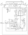
- FIG. 2 is a circuit diagram of a power conversion apparatus according to a second embodiment of the present invention.
- the second embodiment differs from the first embodiment in that the current detector 13 installed in the first embodiment is omitted and the reactive power provided in the control unit 7 in the first embodiment in the control unit 7A.
- the detector 85, the subtractor 86 and the reactive power controller 87 are also omitted, and a holding circuit 95 is added in the control unit 7A of this embodiment, and the signal input of the holding circuit 95 is the output of the 3-phase to 2-phase converter 79.
- the D-axis current feedback is used, the signal output of the holding circuit 95 is connected to the second input of the switch 74 B, and the signal holding operation of the holding circuit 95 follows the holding control signal S95 output from the synchronous input controller 83. That's the point I
- the motor drive mode and the all-speed operation mode are the same as in the first embodiment. However, in these modes, the holding control signal S95 output from the synchronization and entry controller 83 is in a state where the holding circuit 95 does not hold an input.
- the uniform speed mode as in the first embodiment, the frequency and the phase of the voltage of the AC power source 1 detected by the voltage detector 14 and the frequency and phase of the two signals of the voltage command of three phases which is the output of the two-phase to three-phase converter 77
- the synchronous combination controller 83 outputs the speed fine adjustment signal ⁇ s and adds it to the second input of the adder / subtractor 71.
- the voltage fine adjustment signal ⁇ v corresponding to the deviation of the three-phase voltage command (corresponding to the fundamental wave of the output voltage of the inverter 32), which is the output of the phase converter 77, is output and used as the d axis correction current.
- the voltage fine adjustment signal ⁇ v corresponding to the deviation of the three-phase voltage command (corresponding to the fundamental wave of the output voltage of the inverter 32), which is the output of the phase converter 77, is output and used as the d axis correction current.
- an operation signal S6 is output to turn on the switch 6.
- the inverter 32 performs parallel operation with the AC power supply 1.
- the synchronous combination controller 83 After turning on the switch 6, the synchronous combination controller 83 generates a control switching signal to switch the operation of the power converter 3 from the all-speed operation mode to the flux current compensation mode which is a special example of the reactive power control mode. That is, the synchronization input controller 83 changes the switching signal S74A, switches the output signal of the switch 74A from the first input to the second input, changes the switching signal S74B, and changes the output signal of the switch 74B from the first input. It switches to the second input, changes the switching signal S74C, switches the output signal of the switch 74C from the first input to the second input, and sets the outputs of the speed fine adjustment signal ⁇ s and the voltage fine adjustment signal ⁇ v to zero.
- the off operation of the switch 6 involves mechanical operation, a delay of several ms or more is actually involved from the switching of the operation signal S6.
- the operation of changing the holding control signal S95 and holding the input signal by the holding circuit 95 is an operation at the electronic circuit level and is fast.
- the control unit 7A is constituted of, for example, a microprocessor, its delay time is about the operation time of the microprocessor and can be easily realized in 1 ms or less. Therefore, when switching between the holding control signal S95 and the operation signal S6 is simultaneously performed, the holding circuit 95 holds the d-axis current feedback which is the output of the 3-phase to 2-phase converter 77 just before being synchronized. Become.
- the delay relationship can be satisfied.
- the output of the switch 74A goes from the output of the divider 73 to 0, the output of the switch 74B from the output of the flux current converter 73A to the output of the holding circuit 95, and the output of the switch 74C is integrator 82 Switch to the output of the PLL controller 84 respectively.
- the input switch 2 maintains the on state.
- the output of the switch 74A becomes 0 in the magnetic flux current compensation mode.
- the output of the switch 74A corresponds to the torque current reference, and becomes the q-axis current reference in the q-axis current control loop of the inverter 32. Since the output voltage phase of the inverter and the voltage phase of the AC power supply 1 are in synchronization, the q-axis current component output from the inverter 32, that is, the active current component is zero.
- the holding circuit 95 Since the holding circuit 95 holds the d-axis current feedback which is the output of the three-phase to two-phase converter 77 just before being synchronized, the output of the holding circuit 95 is the d-axis current just before being synchronized. It is the value of feedback. That is, the value of the d-axis current feedback immediately before being synchronously input becomes the d-axis current reference in the d-axis current control loop of the inverter 32.
- the d-axis current of the inverter 32 immediately before the synchronization input is a component corresponding to the excitation current of the AC motor 5.
- the d-axis current component output from the inverter 32 becomes an excitation current component of the AC motor 5. Therefore, if the load condition of the AC motor 5 does not change, the q-axis current which is an effective current output by the inverter 32 in the magnetic flux current compensation mode becomes 0, and the d-axis current which is a reactive current compensates for the excitation current. It is controlled.
- FIG. 3 is a circuit diagram of a power conversion device according to a third embodiment of the present invention.
- the control unit 7B calculates a DC voltage detector 34 for detecting a DC voltage which is an output of the diode converter 31 and a difference between the detected voltage and a set voltage reference.
- a voltage controller 89 that outputs the q-axis current reference and provides its output to the second input of the switch 74A. The point is that the switch 2 is operated by the switching signal S2 from the synchronization and entry controller 83.
- the input switch 2 is in the closed state, and after passing through the motor drive mode to become the constant speed operation mode, the synchronous co-entry controller 83 issues a control switching signal to start the power converter 3 from the constant speed operation mode.
- the operation of switching to the reactive power control mode is the same as that of the first embodiment.
- the difference from the first embodiment is that, when switched to the reactive power control mode, the synchronous input controller 83 changes the switching signal S2 to turn off the input switch 2, and the switch 74A changes the second switch.
- the point is to select the q-axis current reference which is the output of the voltage controller 89, not 0, as the input.
- the set voltage reference given to the subtractor 88 is set to a voltage corresponding to the DC output of the diode converter 31 in the all-speed operation mode.
- inverter 32 is regeneratively operated such that the voltage applied to DC capacitor 33 becomes the set voltage reference, and the effective current corresponding to the power loss in power converter 3 is from AC power supply 1 It will flow into the inverter 32.
- the reactive power control is completely the same as that of the first embodiment, so the description thereof is omitted.
- FIG. 4 is a circuit diagram of a power conversion device according to a fourth embodiment of the present invention.
- a control unit 7C calculates a direct current voltage detector 34 for detecting a direct current voltage which is an output of the diode converter 31, and a difference between the detected voltage and a set voltage reference.
- a voltage controller 89 that outputs the q-axis current reference and provides its output to the second input of the switch 74A.
- the switch 2 is operated by the switching signal S2 from the synchronization and entry controller 83.
- the set voltage reference given to the subtractor 88 is set to a voltage corresponding to the DC output of the diode converter 31 in the all-speed operation mode.
- the operation of the fourth embodiment is a combined operation of the second embodiment and the third embodiment, and thus the description thereof is omitted.
- the reactive current of the power converter 3 in the reactive power control mode, is controlled in the magnetic flux current compensation mode, and the voltage applied to the DC capacitor 33 becomes the set voltage reference To be controlled.
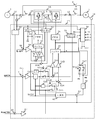
- FIG. 5 is a circuit configuration diagram of a power conversion device according to a fifth embodiment of the present invention.
- the same part as each part of the power converter based on Example 1 of this invention of FIG. 1 is shown with the same code
- the main difference between the fifth embodiment and the first embodiment is that, in the power converter 3A, the diode converter 31 is changed to a self-excited converter 31A, and a control circuit of the self-excited converter 31A is added to the controller 7D. is there. Further, in order to control the current of the self-excited converter 31A, a current detector 15 is provided at the input of the self-excited converter 31A.
- the q-axis active current control in the self-excited converter 31A is performed by comparing the voltage detected by the DC voltage detector 34 with the voltage reference by the subtractor 88 as the inverter 32 performed in the third embodiment.
- the voltage controller 89 outputs the active current reference as follows.
- the reactive power detected by the reactive power detector 85 is compared with the reactive power reference by the subtractor 86, and the difference is minimized.
- the reactive power controller 87 outputs the reactive current reference as follows.
- the three-to-two phase converter 91 converts the three-phase feedback current into q-axis and d-axis feedback currents according to the reference phase ⁇ S detected by the PLL controller 84.
- the effective current reference output from the voltage controller 89 is subtracted from the q-axis feedback current by the subtractor 90A, and the q-axis current controller 92A outputs the q-axis voltage command so as to minimize this difference.
- the signal is supplied to a two-phase to three-phase converter 93.
- the reactive current reference output from reactive power controller 87 is subtracted from the d-axis feedback current by subtractor 90B, and d-axis current controller 92B outputs the d-axis voltage command so that this difference is minimized.
- the two-phase to three-phase converter 93 converts two-phase voltage commands into three-phase AC voltage commands in accordance with the reference phase ⁇ S detected by the PLL controller 84 and supplies the three-phase AC voltage commands to the PWM controller 94.
- the PWM controller 94 supplies a PWM-modulated gate signal to each power device of the self-excited converter 31A such that the input voltage of each phase of the self-excited converter 31A becomes a voltage command of these three phases.
- the synchronization combination controller 83 when the synchronization combination controller 83 performs synchronization combination and switches the power converter 3 from the all-speed operation mode to the reactive power control mode, the divider 73 whose input is the first input of the switch 74A. Switches from the Q axis current reference of the output to 0, which is the second input, from the D axis current reference of the output of the flux current converter 73A which is the first input, the reactive power control which is the second input Switch to the D-axis current reference which is the output of the comparator 87, and the reference phase which is the output of the PLL controller 84 which is the second input from the reference phase .theta.M which is the output of the integrator 82 which is the first input. Switch to ⁇ S.
- FIG. 6 is a circuit configuration diagram of a power conversion device according to a sixth embodiment of the present invention.
- the same part as each part of the power converter based on Example 5 of this invention of FIG. 5 is shown with the same code
- the main points in which this sixth embodiment differs from the fifth embodiment are:
- the control unit 7E a holding circuit 95 is added, the signal input of the holding circuit 95 is D-axis current feedback which is the output of the 3-phase to 2-phase converter 79, and the signal output of the holding circuit 95 is the second of the switch 74B.
- the signal holding operation of the holding circuit 95 is connected to the input and is in accordance with the holding control signal S95 output from the synchronization and entry controller 83.
- the operation of the sixth embodiment is a combined operation of the sixth embodiment and the second embodiment, so that the description thereof will be omitted.
- the self-excited converter 31A performs the reactive power control and the DC voltage constant control regardless of the drive mode, and the inverter 32 is controlled in the reactive current control mode in the reactive power control mode. The current will be controlled to be zero.
- the velocity detector 11 in each embodiment may be a position detector, in which case the velocity may be determined by differentiating the position.
- the speed may be determined indirectly by calculation without providing the speed detector.
- the reactive power control in each embodiment controls the reactive power of the power system to a desired value
- the reactive power detector 85 may be replaced with a power factor detector, and in the case of harmonic suppression control, the harmonic current input to the power system is detected and the detected harmonic current is A harmonic suppression controller to minimize is provided instead of the reactive power controller 87.
- the above harmonic suppression controllers may be provided in parallel while utilizing the control loop of the reactive power controller 87.
- the output switch 4 is switched to the reactive power control while the inverter 32 is on, but after synchronization is performed Alternatively, the output switch 4 may be turned on again after the output switch 4 is turned off and the control system is switched to the reactive power control mode by the switches 74A, 74B and 74C.
- the timing which switches the inverter 32 to reactive power control is performed by a timer, for example.
- the set time of the timer is preferably at least greater than the time constant of the control system of the inverter 32.
- the switching may be performed by detecting that the transient change of the output current of the inverter 32 has settled, regardless of the timer.
- a soft start function may be added to the control system to prevent transient disturbance.
- the output of the 2-phase to 3-phase converter 77 is used on the side of the inverter 32 to detect coincidence of the voltages of the AC power supply 1 and the inverter 32.
- the output voltage of the inverter 32 is directly detected. It may be configured to
- the voltage fine adjustment signal ⁇ v is applied to the second input of the adder-subtractor 75B as the d-axis correction current, but if the output voltage of the inverter 32 can be corrected, the q-axis correction current is used. It may be added to the input or output of the PWM controller 78.
- a limiter may be provided in the reactive current reference Id.
- the inverter 32 in the motor drive mode is operated by vector control, but vector control is not necessary if the condition is satisfied that synchronization is not a problem.
- f may be constant control.
- the two self-excited converters 31A and the inverters 32 operate in parallel in the state of having the same function. Therefore, for example, it is possible to perform switching so as to exchange control of each other.
- the AC motor 5 and the power converter 3 are described as corresponding to 1: 1, for example, a single power converter sequentially activates and synchronizes a plurality of AC motors. Even with such a system configuration, it is possible to switch the inverter 32 to the reactive power control mode and operate after all the motor drive modes are completed.
Landscapes
- Engineering & Computer Science (AREA)
- Power Engineering (AREA)
- Inverter Devices (AREA)
- Control Of Ac Motors In General (AREA)
Abstract
3相の交流電源1を入力とし、直流電圧を出力するコンバータ31と、コンバータ31の出力に接続され、出力開閉器4を介して交流電動機5を駆動するインバータ32と、交流電源1で交流電動機5を直接駆動するための電源開閉器6と、 インバータ32の出力電流を検出する電流検出器12と、コンバータ3の入力側の電源系統の電圧及び電流を夫々検出する電圧検出器14及び電流検出器13と、インバータ32の3相の出力電圧を3相の電圧指令に基づいて制御するための制御部7とで構成する。制御部7は、交流電動機5をベクトル制御するベクトル制御部と、同期併入制御83を有し、同期併入制御83は、電源開閉器6を投入して交流電動機5を交流電源1に同期併入させたあと、制御系を切換えてインバータ32を電源系統の無効電力制御装置として動作させる。
Description
この発明は電力変換装置に係り、特に同期併入機能と無効電力制御機能を共に備えた電力変換装置に関する。
交流電動機を駆動するには、商用の交流電源による固定周波数駆動と、インバータ装置による可変周波数駆動の2種類がある。前者は、交流電動機の運転速度を変化させることは困難であるが、変換器の損失なく所定の速度で運転可能である。逆に後者は交流電動機を可変速駆動することが可能であるが、変換器の損失が発生する。また、前者の場合、大容量の交流電動機の駆動には起動時の突入電流が大きくなるため、これを防ぐ何らかの工夫が必要であった。このため、両者の長所を生かす構成として、商用の交流電源駆動とインバータ装置による駆動を必要に応じて切換える駆動方式が実用化されている。そしてこのような駆動方式を採用するためには、インバータ装置を短時間商用の交流電源とショックレスで並列運転するという所謂同期併入の機能が必要となる。そして、この同期併入の機能を簡単に且つ合理的に行う方法が提案されている(例えば特許文献1参照。)。また、同期併入時に必要になる交流電源とインバータ装置の同期制御に関しては、交流電源とインバータ装置の電圧、周波数を一致させ、さらに位相を一致させる各種方法が提案されている(例えば特許文献2、特許文献3参照。)。
特許文献1に示されている電力変換装置は、交流電動機の速度基準をトリガ信号として同期併入を行うものであるが、同期併入を行ってインバータ装置による駆動から商用の交流電源による駆動に切換えた後、インバータ装置は何ら活用されていないという問題点があった。この問題は、特許文献2、特許文献3に関しても同様である。
本発明は上記問題点に鑑みて為されたもので、同期併入を行ってインバータ装置による駆動から商用の交流電源による駆動に切換えた後もインバータ装置を有効に活用するようにした電力変換装置を提供することを目的とする。
上記目的を達成するために、本発明の電力変換装置は、3相交流電源を入力とし、直流電圧を出力するコンバータと、前記コンバータの出力に接続され、出力開閉器を介して交流電動機を駆動するインバータと、前記交流電源で前記交流電動機を直接駆動するための電源開閉器と、前記インバータの出力電流を検出する第1の電流検出器と、前記コンバータの入力側の電源系統の電圧及び電流を夫々検出する電圧検出器及び第2の電流検出器と、前記インバータの3相の出力電圧を第1の3相の電圧指令に基づいて制御するための制御部とを具備し、前記制御部は、
与えられた速度基準と前記交流電動機の直接または間接的に求められる速度帰還の偏差が最小になるように制御して第1のQ軸電流基準を出力する速度制御器と、前記第1の電流検出器で検出された3相電流を第1の基準位相に基づいて第1のQ軸電流帰還と第1のD軸電流帰還に変換する第1の3相―2相変換器と、前記第1のQ軸電流基準を第1の切換器を介して前記第1のQ軸電流帰還と比較し、その偏差が最小になるように制御して第1のQ軸電圧基準を出力する第1のQ軸電流制御器と、与えられた磁束基準に見合う第1のD軸電流基準を、第2の切換器を介して前記第1のD軸電流帰還と比較し、その偏差が最小になるように制御して第1のD軸電圧基準を出力する第1のD軸電流制御器と、前記第1のQ軸電圧基準及び第1のD軸電圧基準を前記第1の基準位相に基づいて前記第1の3相の電圧指令に変換する第1の2相―3相変換器と、前記速度帰還と前記第1のQ軸電流基準と前記磁束基準とから演算によって前記インバータの出力周波数を求め、これを積分して前記第1の基準位相を求める演算手段と、前記電圧検出器の出力を入力として第2の基準位相を得る位相同期回路と、前記第1の基準位相と前記第2の基準位相を切換える第3の切換器と、前記電圧検出器及び前記第2の電流検出器から系統の無効電力を検出する無効電力検出手段と、
この無効電力を所定の無効電力基準と比較しその偏差が最小となるように制御して第2のD軸電流基準を出力する無効電力制御器と、前記交流電動機を前記インバータによる駆動から前記交流電源による駆動に切換えるための同期併入制御器とを有し、前記同期併入制御器は、前記交流電動機の速度及び前記インバータの出力電圧を調整して前記交流電源と前記インバータの電圧、出力周波数及び位相を一致させたとき、前記電源開閉器を投入して同期併入し、その後前記第1乃至第3の切換器を切換えて前記インバータで前記交流電動機の駆動系統を含む電力系統の無効電力制御を行うようにしたことを特徴としている。
本発明によれば、同期併入を行ってインバータ装置による駆動から商用の交流電源による駆動に切換えた後もインバータ装置を有効に活用する電力変換装置を提供することができる。
以下、図面を参照して本発明の実施例を説明する。
図1は本発明の実施例1に係る電力変換装置の回路構成図である。商用の3相の交流電源1が、電流検出器13を介して入力開閉器2の交流電源側に接続される。さらに入力開閉器2の電力変換器側は電力変換器3のダイオードコンバータ31に接続される。電力変換器3は、ダイオードコンバータ31、直流コンデンサ33及びインバータ32より構成される。ダイオードコンバータ31の直流出力は直流コンデンサ33で平滑化されインバータ32に入力される。インバータ32の交流出力は電流検出器12を経由し、さらに出力開閉器4を介して交流電動機5を駆動する。また、交流電源1から交流電動機5を直接駆動することができるように開閉器6が設けられている。即ち、開閉器6の交流電源側は入力開閉器2の交流電源側に接続され、開閉器6の交流電動機側は出力開閉器4の交流電動機側に接続されている。
インバータ32は電圧型のPWM変換器である。インバータ32を構成するパワーデバイスは、制御部7から与えられるゲート信号によりオンオフ制御されている。交流電動機5には速度検出器11が取り付けられており、この出力は制御部7に与えられる。また、インバータ32の出力側には電流検出器12が設けられ、この出力も制御部7に与えられる。入力開閉器2の交流電源側は電圧検出器14が設けられている。電流検出器13と電圧検出器14の出力も制御部7に与えられている。
次に制御部7の内部構成について説明する。始めに、開閉器6をオフし、入力開閉器2及び出力開閉器4をオンした状態で交流電動機5を可変速駆動する場合について説明する。ここで開閉器6の操作信号S6は後述される同期併入制御器83によって操作される。ここで、交流電動機5を可変速駆動する場合を電動機駆動モードと呼ぶ。
外部から与えられる速度基準は加減算器71の第1入力に接続される。加減算器71の第2入力には、後述する同期併入制御器83の出力である速度微調整信号Δωsが入力される。交流電動機5を起動して可変速駆動している期間は、同期併入制御器83の出力である速度微調整信号Δωsは0となるよう様に設定される。速度検出器11で得られる速度帰還は、加減算器71の第3入力に接続される。加減算器71では第1入力と第2入力の和から第3入力の差分が演算され、速度制御器72に与えられる。速度制御器72は例えばPI制御器である。そして速度制御器72は与えられた差分が最小となるように調節制御してトルク基準を出力する。このトルク基準は除算器73によって別途設定された磁束基準で除算され、トルク電流基準となる。このトルク電流基準は切換器74Aの第1入力に接続されている。また切換器74Aの第2入力には0が入力されている。切換器74Aの出力は減算器75Aに接続されている。切換器74Aの切換え信号S74Aは後述する同期併入制御器83によって操作される。交流電動機5を起動して可変速駆動している電動機駆動モードの期間は、切換器74Aの切換え信号S74Aは切換器74Aの出力が第1入力を選択する様に設定される。よって、この期間においてはトルク電流基準は切換器74Aを介して減算器75Aの第1入力に与えられることになる。また、磁束基準を磁束電流変換器73Aに与えることによって磁束電流基準を得る。磁束電流変換器73Aの出力である磁束電流基準は切換器74Bの第1入力に接続されている。また切換器74Bの第2入力には後述される無効電力制御器87の出力が接続されている。切換器74Bの出力は加減算器75Bの第1入力に接続されている。切換器74Bの切換え信号S74Bは後述する同期併入制御器83によって操作される。電動機駆動モードの期間は、切換器74Bの切換え信号S74Bは切換器74Bの出力が第1入力を選択する様に設定される。よって、この期間は、磁束電流基準は切換器74Bを介して加減算器75Bに与えられることになる。加減算器75Bの第2入力には後述する同期併入制御器83の出力である電圧微調整信号Δvが入力される。また、電動機駆動モードの期間は、同期併入制御器83の出力である電圧微調整信号Δvは0となるよう様に設定される。
電流検出器12で検出された3相の出力電流は3相―2相変換器79に与えられる。3相―2相変換器79はこの3相電流を後述する切換器74Cの出力である基準位相θで互いに直交する2軸の直流成分に変換する。基準位相θを適切に選定することによって、この2軸の電流成分を、トルク電流帰還であるQ軸電流帰還と、これと直交する磁束電流帰還であるD軸電流帰還とすることができる。Q軸電流帰還は減算器75Aの減算入力として与えられ、減算器75Aの第1入力との差分がQ軸電流制御器76Aに与えられる。D軸電流帰還は加減算器75Bの第3入力として与えられ、加減算器75Bの第1入力と第2入力との和と第3入力との差分がD軸電流制御器76Bに与えられる。
Q軸電流制御器76A及びD軸電流制御器76Bは例えばPI制御器であり、夫々の入力が最小となるように調節制御して夫々Q軸電圧指令及びD軸電圧指令を出力して2相―3相変換器77に与える。2相―3相変換器77は、切換器74Cの出力である基準位相θを用いてQ軸電圧指令及びD軸電圧指令を3相の電圧指令に変換し、その出力をPWM制御器78に与える。PWM制御器78はインバータ32の各相の出力電圧がこの3相の電圧指令となるようにインバータ32の各パワーデバイスに対して、PWM変調されたゲート信号を供給する。
以下、基準位相θについて説明する。交流電動機5が誘導電動機とすると、前述の磁束基準と除算器73の出力であるトルク電流基準からすべり演算器80によって誘導電動機のすべりsを求める。このすべりsを加算器81によって速度帰還に加算することによってインバータ32の出力周波数が求まり、この出力周波数を積分器82で積分することによって交流電動機Mの入力端子電圧の基準位相θMが得られる。積分器87の出力である基準位相θMは切換器74Cの第1入力に接続されている。また切換器74Cの第2入力には、後述されるPLL制御器84の出力である交流電源1の電圧に同期した基準位相θSが入力されている。切換器74Cの出力が基準位相θである。切換器74Cの切換え信号S74Cは後述する同期併入制御器83によって操作される。電動機駆動モードの期間は、切換器74Cの切換え信号S74Cは切換器74Cの出力が第1入力を選択する様に設定される。よって、この期間は、交流電動機Mの入力端子電圧の基準位相θMが基準位相θとなり切換器74Cを介して2相―3相変換器77と3相―2相変換器79に与えられる。
以上説明した構成によって、入力開閉器2及び出力開閉器4をオンした状態で交流電動機5を可変速駆動することが可能となる。また、以上説明した構成は、切換器74A、74B及び74C等を除き、交流電動機5を所謂ベクトル制御するための構成要件から成っている。 尚、本実施例においては、外部から与られる速度基準は所定のレートをもって回転速度がゼロから交流電動機5が交流電源1で直接駆動された場合の回転速度相当まで上昇するように設定することにより、インバータ32の基本波出力周波数を交流電源1と同一の周波数にすることができる。
次に同期併入と、同期併入後の無効電力制御に係る構成を説明する。電圧検出器14で検出された交流電源1の電圧の位相は、PLL制御器84によって検出され、基準位相θSを得る。PLL制御器84とはフェーズロックドループを使用した位相同期回路であり、交流電源1の電圧に同期した基準位相θSを出力する。ここで交流電源の電圧位相と同相分がq軸、それと直交する成分がd軸となるように基準位相θSを定めるものとする。同期併入制御器83には、監視入力として、電圧検出器14で検出される交流電源1の電圧と、PLL制御器84の出力である交流電源1の電圧に同期した基準位相θSと、2相―3相変換器77の出力である3相の電圧指令と、積分器82の出力である交流電動機Mの入力端子電圧の基準位相θMが入力される。3相の電圧指令はインバータ32の基本波電圧出力に相当する信号である。同期併入制御器83は交流電動機5が交流電源1で直接駆動された場合の回転速度相当まで上昇し、電圧検出器14で検出される交流電源1の電圧の周波数と2相―3相変換器77の出力である3相の電圧指令の周波数の差分が所定の範囲内になると、交流電源1の電圧とインバータ32の出力電圧の基本波との、電圧と周波数と位相を一致させるための、いわゆる揃速制御をおこなう。ここで揃速制御を行う場合を揃速モードと呼ぶ。すなわち交流電動機5が交流電源1で直接駆動された場合の回転速度相当まで上昇し、電圧検出器14で検出される交流電源1の電圧の周波数と2相―3相変換器77の出力である3相の電圧指令の周波数との差分が所定の範囲内になると、電動機駆動モードから揃速モードに移行する。
揃速モードになると、上記の2信号の周波数と電圧及び位相を一致させるため、本実施例においては、同期併入制御器83が速度微調整信号Δωsを出力し、加減算器71の第2入力に加える、さらに電圧検出器14で検出される交流電源1の電圧と2相―3相変換器77の出力である3相の電圧指令(インバータ32の出力電圧の基本波に相当)の偏差を調整するための電圧微調整信号Δvを出力し、d軸補正電流として、減算器75Bの第2入力に与える。そして、電圧検出器14で検出される交流電源1の電圧の周波数と2相―3相変換器77の出力である3相の電圧指令の電圧、周波数、位相(基準位相θSと基準位相θM)が一致する(厳密には偏差が所定の許容範囲内になる。)と同期併入指令を出力し、開閉器6をオンさせるように操作信号S6を出力する。同期併入制御器83の揃速制御機能の詳細については例えば特許文献2、特許文献3に記されているのでその説明は省略する。
開閉器6をオンするとインバータ32は交流電源1と並列運転を行うことになる。開閉器6をオン後、同期併入制御器83は制御切換え信号を発し、電力変換器3の動作を揃速運転モードから無効電力制御モードに切換える。すなわち同期併入制御器83は切換信号S74Aを変更し、切換器74Aの出力信号を第1入力から第2入力に切換え、切換信号S74Bを変更し、切換器74Bの出力信号を第1入力から第2入力に切換え、切換信号S74Cを変更し、切換器74Cの出力信号を第1入力から第2入力に切換え、さらに速度微調整信号Δωsおよび電圧微調整信号Δvの出力を0にする。すなわち切換器74Aの出力を除算器73の出力から0へ、切換器74Bの出力を磁束電流変換器73Aの出力から無効電力制御器87の出力へ、更に切換器74Cの出力を積分器82の出力からPLL制御器84の出力へ夫々切換える。ここで入力開閉器2はオンの状態を維持する。
以上により、無効電力制御モードでは切換器74Aの出力は0となる。切換器74Aの出力はトルク電流基準相当であり、インバータ32のq軸電流制御ループに於いてq軸電流基準になる。インバータ32の出力電圧位相と交流電源1の電圧位相は同期しているので、インバータ32から出力されるq軸電流成分、即ち有効電流成分は0となる。
ここで、無効電力制御器87について説明する。電流検出器13の出力と電圧検出器14の出力が無効検出器85に入力され無効電力検出器85は電流検出器13を通過する無効電力を検出する。即ち、本実施例では交流電動機5と電力変換器3の合計の無効電力を検出する。無効電力検出器85の出力は減算器86の減算端子に入力される。減算器86の加算端子には外部で設定された無効電力基準が入力される。無効電力基準と無効電力検出器85の差分は無効電力制御器87に入力される。無効電力制御器87は例えばPI制御器である。そして与えられた差分か最小になる様に調節制御してその出力を切換器74Bの第2入力へ出力する。無効電力制御モードでは切換器74Bの出力は第2入力となる。切換器74Bの出力である即ち無効電力制御器87の出力が、インバータ32のd軸電流制御ループに於いてd軸電流基準になる。インバータの出力電圧位相と交流電源1の電圧位相は同期しているので、インバータ32から出力されるd軸電流成分は即ち無効電流成分となる。よって、無効電力制御モードにおいてインバータ32が出力する有効電流であるq軸電流は0となり、無効電流であるd軸電流は無効電力制御器87の出力になるように制御される。言い換えれば、電力変換器3で消費される電力損失はダイオードコンバータ31から給電され、電力変換器3は電流検出器13が接続された交流電動機5を含んだ電力系統全体として、外部から与えられる無効電力基準となるような無効電流を出力する無効電力制御装置として機能することになる。
たとえば、減算器86に外部から与えられる無効電力基準を0に設定すれば、無効電力制御モードにおいて、電流検出器13の接続されている電力系統で発生する無効電力が0になるようにインバータ31は無効電力を発生する。即ち、交流電動機5を駆動する電力と電力変換器3の入力電力の合計の力率が1となる運転をすることができる。
さらに、交流電源1に接続された、図示されていない別の負荷Lが接続されている他の電力系統で発生する無効電力を検出する無効電力検出器の出力を、減算器86の減算端子に接続するように構成すると、無効電力制御モードにおいて、電力変換装置3は、他の電力系統の無効電力を制御することができる。他の電力系統に交流電動機5の駆動系が接続されていれば、電力変換装置3は、交流電動機5の駆動系の無効電力のみではなく負荷Lの無効電力も補償する運転を行う事ができる。
図2は本発明の実施例2に係る電力変換装置の回路構成図である。この実施例2の各部について、図1の本発明の実施例1に係る電力変換装置の各部と同一部分は同一符号で示し、その説明は省略する。この実施例2が実施例1と異なる点は、実施例1において、設置されていた電流検出器13を省略すると共に、制御部7Aにおいて、実施例1で制御部7に設けられていた無効電力検出器85、減算器86及び無効電力制御器87も省略し、本実施例の制御部7Aにおいて保持回路95を追加し、保持回路95の信号入力は3相―2相変換器79の出力であるD軸電流帰還とし、保持回路95の信号出力は切換器74Bの第2入力に接続し、保持回路95の信号保持動作は、同期併入制御器83から出力される保持制御信号S95に従う様にした点である。
この実施例2の動作について以下説明する。電動機駆動モード及び揃速運転モードまでは実施例1と同様である。ただし、これらのモードにおいては同期併入制御器83から出力される保持制御信号S95は保持回路95が入力を保持しない状態とする。揃速モード中では実施例1と同様に、電圧検出器14で検出される交流電源1の電圧と2相―3相変換器77の出力である3相の電圧指令の2信号の周波数と位相を一致させるため、同期併入制御器83が速度微調整信号Δωsを出力し、加減算器71の第2入力に加える、さらに電圧検出器14で検出される交流電源1の電圧と2相―3相変換器77の出力である3相の電圧指令(インバータ32の出力電圧の基本波に相当)の偏差に相当する電圧微調整信号Δvを出力し、d軸補正電流として、減算器75Bの第2入力に与える。そして、電圧検出器14で検出される交流電源1の電圧の周波数と2相―3相変換器77の出力である3相の電圧指令の周波数、電圧、位相(基準位相θSと基準位相θM)が一致する(厳密には偏差が所定の許容範囲内になる。)と同期併入指令を出力し、保持制御信号S95を変化させ保持回路95がその入力信号を保持し、保持した入力信号と等しい信号を出力する。同時に開閉器6をオンさせるように操作信号S6を出力する。開閉器6をオンするとインバータ32は交流電源1と並列運転を行うことになる。開閉器6をオン後、同期併入制御器83は制御切換え信号を発し、電力変換器3の動作を揃速運転モードから無効電力制御モードの特例である磁束電流補償モードに切換える。すなわち同期併入制御器83は切換信号S74Aを変更し、切換器74Aの出力信号を第1入力から第2入力に切換え、切換信号S74Bを変更し、切換器74Bの出力信号を第1入力から第2入力に切換え、切換信号S74Cを変更し、切換器74Cの出力信号を第1入力から第2入力に切換え、さらに速度微調整信号Δωsおよび電圧微調整信号Δvの出力を0にする。
ここで、開閉器6のオフ動作は機械的な動作を伴うので操作信号S6の切換えから実際には数ms以上の遅延を伴う。これにし、保持制御信号S95を変化させ保持回路95がその入力信号を保持させる動作は電子回路レベルの動作であり高速である。制御部7Aは例えばマイクロプロセッサによって構成されるので、その遅延時間はマイクロプロセッサの演算時間程度であり1ms以下で実現することは容易である。したがって、保持制御信号S95と操作信号S6の切換えを同時に実施した場合、保持回路95は同期併入される直前の3相―2相変換器77の出力であるd軸電流帰還を保持することになる。尚マイクロプロセッサの演算時間が1ms以上の場合や開閉器6が半導体スイッチを使用しており、遅延関係が逆転の可能性がある場合には、操作信号S6の切換え発信時に遅延を持たせ、最終的には遅延関係を満足するようにすることができる。
このようにして切換器74Aの出力を除算器73の出力から0へ、切換器74Bの出力を磁束電流変換器73Aの出力から保持回路95の出力へ、更に切換器74Cの出力を積分器82の出力からPLL制御器84の出力へ夫々切換える。ここで入力開閉器2はオンの状態を維持する。
以上により、磁束電流補償モードでは切換器74Aの出力は0となる。切換器74Aの出力はトルク電流基準相当であり、インバータ32のq軸電流制御ループに於いてq軸電流基準になる。インバータの出力電圧位相と交流電源1の電圧位相は同期しているので、インバータ32から出力されるq軸電流成分、即ち有効電流成分は0となる。
保持回路95は同期併入される直前の3相―2相変換器77の出力であるd軸電流帰還を保持しているので、保持回路95の出力は同期併入される直前のd軸電流帰還の値となる。即ち同期併入される直前のd軸電流帰還の値が、インバータ32のd軸電流制御ループに於いてd軸電流基準になる。同期併入直前のインバータ32のd軸電流は交流電動機5の励磁電流に相当する成分である。インバータの出力電圧位相と交流電源1の電圧位相は同期しているので、インバータ32から出力されるd軸電流成分は即ち交流電動機5の励磁電流成分となる。よって、交流電動機5の負荷条件が変化しなければ、磁束電流補償モードにおいてインバータ32が出力する有効電流であるq軸電流は0となり、無効電流であるd軸電流は励磁電流を補償する様に制御される。
図3は本発明の実施例3に係る電力変換装置の回路構成図である。この実施例3の各部について、図1の本発明の実施例1に係る電力変換装置の各部と同一部分は同一符号で示し、その説明は省略する。この実施例3が実施例1と異なる点は、制御部7Bにおいて、ダイオードコンバータ31の出力である直流電圧を検出する直流電圧検出器34、この検出電圧と設定された電圧基準との差分を演算する減算器88、及びこの差分が最小となるように制御してq軸電流基準を出力し、その出力を切換器74Aの第2入力に与える電圧制御器89を設けた点であり、更に入力開閉器2が同期併入制御器83からの切換え信号S2によって操作されるようにした点である。
この実施例3の動作について以下説明する。まず、入力開閉器2は閉状態であり、電動機駆動モードを経て、揃速運転モードとなった後、同期併入制御器83が制御切換え信号を発し、電力変換器3を揃速運転モードから無効電力制御モードに切換える動作は実施例1と同様である。実施例1と異なるのは、無効電力制御モードに切り換わったとき、同期併入制御器83は切換え信号S2を変更し、入力開閉器2をオフする点、また、切換器74Aが、第2入力として、0ではなく、電圧制御器89の出力であるq軸電流基準を選択する点である。ここで、例えば減算器88に与えられる設定された電圧基準は、揃速運転モードにおけるダイオードコンバータ31の直流出力に相当する電圧に設定する。このようにすれば、直流コンデンサ33に印加される電圧が、設定された電圧基準となるようにインバータ32が回生運転され、電力変換器3内の電力損失分に見合う有効電流が交流電源1からインバータ32に流入することになる。尚、無効電力制御については実施例1と全く同様の制御となるのでその説明は省略する。
図4は本発明の実施例4に係る電力変換装置の回路構成図である。この実施例4の各部について、図2の本発明の実施例2に係る電力変換装置の各部と同一部分は同一符号で示し、その説明は省略する。この実施例4が実施例2と異なる点は、制御部7Cにおいて、ダイオードコンバータ31の出力である直流電圧を検出する直流電圧検出器34、この検出電圧と設定された電圧基準との差分を演算する減算器88、及びこの差分が最小となるように制御してq軸電流基準を出力し、その出力を切換器74Aの第2入力に与える電圧制御器89を設けた点であり、更に入力開閉器2が同期併入制御器83からの切換え信号S2によって操作されるようにした点である。また、例えば減算器88に与えられる設定された電圧基準は、揃速運転モードにおけるダイオードコンバータ31の直流出力に相当する電圧に設定する。
この実施例4の動作については、実施例2と実施例3の組み合わせ動作であるのでその説明は省略する。この実施例4によれば、無効電力制御モードにおいて、電力変換器3の無効電流は磁束電流補償モードで制御され、有効電流は直流コンデンサ33に印加される電圧が、設定された電圧基準となるように制御されることになる。
図5は本発明の実施例5に係る電力変換装置の回路構成図である。この実施例5の各部について、図1の本発明の実施例1に係る電力変換装置の各部と同一部分は同一符号で示し、その説明は省略する。この実施例5が実施例1と異なる主な点は、電力変換器3Aにおいて、ダイオードコンバータ31を自励コンバータ31Aに変更し、制御部7Dにこの自励コンバータ31Aの制御回路を追加した点である。また、自励コンバータ31Aの電流制御を行うため、自励コンバータ31Aの入力に電流検出器15を設けている。
自励コンバータ31Aにおけるq軸の有効電流制御は、実施例3でインバータ32が行ったように、直流電圧検出器34で検出された電圧を減算器88で電圧基準と比較し、その差分が最小となるように電圧制御器89が有効電流基準を出力することによって行う。また、d軸の無効電流制御は、実施例1でインバータ32が行ったように、無効電力検出器85で検出された無効電力を減算器86で無効電力基準と比較し、その差分が最小となるように無効電力制御器87が無効電流基準を出力することによって行う。3相-2相変換器91はPLL制御器84が検出した基準位相θSに従って3相の帰還電流をq軸及びd軸の帰還電流に変換する。そして電圧制御器89が出力する有効電流基準は減算器90Aによってq軸帰還電流との差分がとられ、q軸電流制御器92Aはこの差分が最小となるようにq軸電圧指令を出力して2相―3相変換器93に与える。同様に無効電力制御器87が出力する無効電流基準は減算器90Bによってd軸帰還電流との差分がとられ、d軸電流制御器92Bはこの差分が最小となるようにd軸電圧指令を出力して2相―3相変換器93に与える。2相―3相変換器93はPLL制御器84が検出した基準位相θSに従って2相の電圧指令を3相の交流電圧指令に変換してPWM制御器94に与える。PWM制御器94は自励コンバータ31Aの各相の入力電圧がこの3相の電圧指令となるように自励コンバータ31Aの各パワーデバイスに対して、PWM変調されたゲート信号を供給する。
この構成において、同期併入制御器83は、同期併入を行って電力変換器3を揃速運転モードから無効電力制御モードに切換えるとき、切換器74Aの入力を第1入力である除算器73の出力のQ軸電流基準から第2入力である0に切換え、切換器74Bの入力を第1入力である磁束電流変換器73Aの出力のD軸電流基準から、第2入力である無効電力制御器87の出力であるD軸電流基準に切換え、切換器74Cの入力を第1入力である積分器82の出力である基準位相θMから第2入力であるPLL制御器84の出力である基準位相θSに切換える。
以上の構成によれば、交流電動機5をインバータ32で駆動している電動機駆動モードであっても自励コンバータ31Aによって電源系統の無効電力制御が可能となる。通常、自励コンバータ31Aはインバータ32とほぼ同一の容量であるので、交流電動機5を同期併入したあとの制御の切換えによって、倍の容量の無効電力制御を行うことが可能となる。
図6は本発明の実施例6に係る電力変換装置の回路構成図である。この実施例6の各部について、図5の本発明の実施例5に係る電力変換装置の各部と同一部分は同一符号で示し、その説明は省略する。この実施例6が実施例5と異なる主な点は、
制御部7Eにおいて、保持回路95を追加し、保持回路95の信号入力は3相―2相変換器79の出力であるD軸電流帰還とし、保持回路95の信号出力は切換器74Bの第2入力に接続し、保持回路95の信号保持動作は、同期併入制御器83から出力される保持制御信号S95に従う様にした点である。
制御部7Eにおいて、保持回路95を追加し、保持回路95の信号入力は3相―2相変換器79の出力であるD軸電流帰還とし、保持回路95の信号出力は切換器74Bの第2入力に接続し、保持回路95の信号保持動作は、同期併入制御器83から出力される保持制御信号S95に従う様にした点である。
この実施例6の動作については、実施例6と実施例2の組み合わせ動作であるのでその説明は省略する。この実施例6によれば、自励コンバータ31Aは駆動モードに拘わらず無効電力制御及び直流電圧一定制御を行い、インバータ32は無効電力制御モードにおいて、無効電流は磁束電流補償モードで制御され、有効電流は0となるように制御されることになる。
以上本発明の実施例を説明したが、これは例として提示したものであり、発明の範囲を限定することは意図していない。この新規な実施例は、その他の様々な形態で実施されることが可能であり、発明の要旨を逸脱しない範囲で、種々の省略、置き換え、変更を行うことができる。これら実施例やその変形は、発明の範囲や要旨に含まれるとともに、特許請求の範囲に記載された発明とその均等の範囲に含まれる。
例えば、各実施例における、速度検出器11は、位置検出器であっても良く、その場合は位置を微分して速度を求めれば良い。また、速度検出器を設けずに速度を演算によって間接的に求めるようにしても良い。
また、各実施例における無効電力制御は、電力系統の無効電力を所望の値に制御すると説明したが、電力系統の力率を制御することも、また高調波を抑制制御することも可能である。力率を制御する場合は無効電力検出器85を力率検出器に置き換えれば良く、高調波抑制制御の場合は、電力系統に入力される高調波電流を検出し、検出された高調波電流を最小化するような高調波抑制御器を無効電力制御器87に代えて設ける。尚、無効電力制御器87の制御ループを活かしたまま上記高調波抑制御器を並列に設ける構成としても良い。
また、各実施例においては、開閉器6を投入して同期併入を行ったあと、出力開閉器4はオン状態のままインバータ32を無効電力制御に切換えると説明したが、同期併入したあと、一旦出力開閉器4をオフし、切換器74A、74B及び74Cによって制御系を無効電力制御モードに切換えたあと、出力開閉器4を再投入しても良い。
また、開閉器6を投入して同期併入を行ったあと、インバータ32を無効電力制御に切換えるタイミングは、例えばタイマーによって行う。タイマーの設定時間は少なくともインバータ32の制御系の時定数より大きくすることが好ましい。また、タイマーに拠らず、インバータ32の出力電流の過渡変化が落ち着いたことを検出して切換えるようにしても良い。
また、制御系を無効電力制御モードに切換えるとき、過渡擾乱を防ぐため、制御系にソフトスタート機能を追加するようにしても良い。
また、各実施例では、交流電源1とインバータ32の電圧の一致を検出するのにインバータ32側について、2相―3相変換器77の出力を用いたが、インバータ32の出力電圧を直接検出するように構成しても良い。
また、各実施例において、電圧微調整信号Δvをd軸補正電流として、加減算器75Bの第2入力に与える構成としたが、インバータ32の出力電圧を補正可能であれば、q軸補正電流としても良く、またPWM制御器78の入力または出力に加えるようにしても良い。
また、例えば無効電力制御の動作において、無効電流基準Idがインバータ32の能力を超える場合を考慮し、無効電流基準Idにリミタを設けるようにしても良い。
また、各実施例においては、電動機駆動モードから無効電力制御モードに切換える説明のみを行ったが、制御の手順を逆にすれば、無効電力制御モードから電動機制御モードに切換えることが可能なことは明らかである。
また、各実施例において、電動機駆動モードにおけるインバータ32はベクトル制御で運転されると説明したが、同期併入が問題なく行われる条件が満たされていれば、ベクトル制御の必要はなく、V/f一定制御であっても良い。
また、実施例5、6において、無効電力制御モードになると、自励コンバータ31Aとインバータ32は同一機能を有する状態で2台が並列運転することになる。従って、例えば、互いの制御を入れ替えるような切換えを行うことも可能となる。
更に、各実施例において、交流電動機5と電力変換器3は1:1で対応するものと記載したが、例えば1台の電力変換器で複数台の交流電動機を順次起動して同期併入するようなシステム構成であっても、全ての電動機駆動モードが完了したあと、インバータ32を無効電力制御モードに切換えて運転することも可能である。
1 交流電源
2 入力開閉器
3、3A 電力変換器
4 出力開閉器
5 交流電動機
6 開閉器
7、7A、7B 制御部
11 速度検出器
12 電流検出器
13 電流検出器
14 電圧検出器
31 ダイオードコンバータ
31A 自励コンバータ
32 インバータ
33 直流コンデンサ
34 直流電圧検出器
71、75B 加減算器
72 速度制御器
73 除算器
73A 磁束電流変換器
74A、74B、74C 切換器
75A 減算器
76A、76B 電流制御器
77 2相―3相変換器
78 PWM制御器
79 3相―2相変換器
80 すべり演算器
81 加算器
82 積分器
83 同期併入制御器
84 PLL制御器
85 無効電力検出器
86 減算器
87 無効電力制御器
88 減算器
89 電圧制御器
90A、90B 減算器
91 3相―2相変換器
92A、92B 電流制御器
93 2相―3相変換器
94 PWM制御器
95 保持回路
Claims (8)
- 3相交流電源を入力とし、直流電圧を出力するコンバータと、
前記コンバータの出力に接続され、出力開閉器を介して交流電動機を駆動するインバータと、
前記交流電源で前記交流電動機を直接駆動するための電源開閉器と、
前記インバータの出力電流を検出する第1の電流検出器と、
前記コンバータの入力側の電源系統の電圧及び電流を夫々検出する電圧検出器及び第2の電流検出器と、
前記インバータの3相の出力電圧を第1の3相の電圧指令に基づいて制御するための制御部と
を具備し、
前記制御部は、
与えられた速度基準と前記交流電動機の直接または間接的に求められる速度帰還の偏差が最小になるように制御して第1のQ軸電流基準を出力する速度制御器と、
前記第1の電流検出器で検出された3相電流を第1の基準位相に基づいて第1のQ軸電流帰還と第1のD軸電流帰還に変換する第1の3相―2相変換器と、
前記第1のQ軸電流基準を第1の切換器を介して前記第1のQ軸電流帰還と比較し、その偏差が最小になるように制御して第1のQ軸電圧基準を出力する第1のQ軸電流制御器と、
与えられた磁束基準に見合う第1のD軸電流基準を、第2の切換器を介して前記第1のD軸電流帰還と比較し、その偏差が最小になるように制御して第1のD軸電圧基準を出力する第1のD軸電流制御器と、
前記第1のQ軸電圧基準及び第1のD軸電圧基準を前記第1の基準位相に基づいて前記第1の3相の電圧指令に変換する第1の2相―3相変換器と、
前記速度帰還と前記第1のQ軸電流基準と前記磁束基準とから演算によって前記インバータの出力周波数を求め、これを積分して前記第1の基準位相を求める演算手段と、
前記電圧検出器の出力を入力として第2の基準位相を得る位相同期回路と、
前記第1の基準位相と前記第2の基準位相を切換える第3の切換器と、
前記電圧検出器及び前記第2の電流検出器から系統の無効電力を検出する無効電力検出手段と、
この無効電力を所定の無効電力基準と比較しその偏差が最小となるように制御して第2のD軸電流基準を出力する無効電力制御器と、
前記交流電動機を前記インバータによる駆動から前記交流電源による駆動に切換えるための同期併入制御器と
を有し、
前記同期併入制御器は、前記交流電動機の速度及び前記インバータの出力電圧を調整して前記交流電源と前記インバータの電圧、出力周波数及び位相を一致させたとき、前記電源開閉器を投入して同期併入し、その後前記第1乃至第3の切換器を切換えて前記インバータで前記交流電動機の駆動系統を含む電力系統の無効電力制御を行うようにしたことを特徴とする電力変換装置。 - 3相交流電源を入力とし、直流電圧を出力するコンバータと、
前記コンバータの出力に接続され、出力開閉器を介して交流電動機を駆動するインバータと、
前記交流電源で前記交流電動機を直接駆動するための電源開閉器と、
前記インバータの出力電流を検出する第1の電流検出器と、
前記コンバータの入力側の電源系統の電圧を電圧検出器と、
前記インバータの3相の出力電圧を第1の3相の電圧指令に基づいて制御するための制御部と
を具備し、
前記制御部は、
与えられた速度基準と前記交流電動機の直接または間接的に求められる速度帰還の偏差が最小になるように制御して第1のQ軸電流基準を出力する速度制御器と、
前記第1の電流検出器で検出された3相電流を第1の基準位相に基づいて第1のQ軸電流帰還と第1のD軸電流帰還に変換する第1の3相―2相変換器と、
前記第1のQ軸電流基準を第1の切換器を介して前記第1のQ軸電流帰還と比較し、その偏差が最小になるように制御して第1のQ軸電圧基準を出力する第1のQ軸電流制御器と、
与えられた磁束基準に見合う第1のD軸電流基準を、第2の切換器を介して前記第1のD軸電流帰還と比較し、その偏差が最小になるように制御して第1のD軸電圧基準を出力する第1のD軸電流制御器と、
前記第1のQ軸電圧基準及び第1のD軸電圧基準を前記第1の基準位相に基づいて前記第1の3相の電圧指令に変換する第1の2相―3相変換器と、
前記速度帰還と前記第1のQ軸電流基準と前記磁束基準とから演算によって前記インバータの出力周波数を求め、これを積分して前記第1の基準位相を求める演算手段と、
前記電圧検出器の出力を入力として第2の基準位相を得る位相同期回路と、
前記第1の基準位相と前記第2の基準位相を切換える第3の切換器と、
前記第1のD軸電流帰還を所定のタイミングで保持して第3のD軸電流基準を出力する保持手段と、
前記交流電動機を前記インバータによる駆動から前記交流電源による駆動に切換えるための同期併入制御器と
を有し、
前記同期併入制御器は、前記交流電動機の速度及び前記インバータの出力電圧を調整して前記交流電源と前記インバータの電圧、出力周波数及び位相を一致させたとき、前記電源開閉器を投入して同期併入し、その後前記第1乃至第3の切換器を切換えて前記インバータで前記交流電動機の励磁電流を補償するような無効電力制御を行うようにすると共に、前記所定のタイミングは前記同期併入の直前のタイミングとしたことを特徴とする電力変換装置。
- 前記コンバータはダイオードコンバータであり、
前記同期併入制御器は、前記同期併入のあと、
前記第1の切換器の入力を前記第1のQ軸電流基準から0に切換え、
前記第2の切換器の入力を前記第1のD軸電流基準から前記第2のD軸電流基準に切換え、
前記第3の切換器の入力を前記第1の基準位相から前記第2の基準位相に切換えるようにしたことを特徴とする請求項1に記載の電力変換装置。 - 前記コンバータはダイオードコンバータであり、
前記同期併入制御器は、前記同期併入のあと、
前記第1の切換器の入力を前記第1のQ軸電流基準から0に切換え、
前記第2の切換器の入力を前記第1のD軸電流基準から前記第3のD軸電流基準に切換え、
前記第3の切換器の入力を前記第1の基準位相から前記第2の基準位相に切換えるようにしたことを特徴とする請求項2に記載の電力変換装置。 - 前記コンバータはその入力側に入力開閉器を備えたダイオードコンバータであり、前記コンバータの出力電圧を検出する直流電圧検出器と、この検出電圧を所定の電圧基準と比較しその偏差が最小となるように制御して第2のQ軸電流基準を出力する電圧制御器とを更に具備し、
前記同期併入制御器は、前記同期併入のあと、
前記入力開閉器をオフし、
前記第1の切換器の入力を前記第1のQ軸電流基準から前記第2のQ軸電流基準に切換え、
前記第2の切換器の入力を前記第1のD軸電流基準から前記第2のD軸電流基準に切換え、
前記第3の切換器の入力を前記第1の基準位相から前記第2の基準位相に切換えるようにしたことを特徴とする請求項1に記載の電力変換装置。 - 前記コンバータはその入力側に入力開閉器を備えたダイオードコンバータであり、前記コンバータの出力電圧を検出する直流電圧検出器と、この検出電圧を所定の電圧基準と比較しその偏差が最小となるように制御して第2のQ軸電流基準を出力する電圧制御器とを更に具備し、
前記同期併入制御器は、前記同期併入のあと、
前記入力開閉器をオフし、
前記第1の切換器の入力を前記第1のQ軸電流基準から前記第2のQ軸電流基準に切換え、
前記第2の切換器の入力を前記第1のD軸電流基準から前記第3のD軸電流基準に切換え、
前記第3の切換器の入力を前記第1の基準位相から前記第2の基準位相に切換えるようにしたことを特徴とする請求項2に記載の電力変換装置。 - 前記コンバータは入力側に入力電流検出器を備えた自励コンバータであり、
前記制御部は、
前記自励コンバータの3相の出力電圧を第2の3相の電圧指令に基づいて制御するために、
前記入力電流検出器で検出された3相電流を前記第2の基準位相に基づいて第2のQ軸電流帰還と第2のD軸電流帰還に変換する第2の3相―2相変換器と、
前記自励コンバータの出力電圧を検出する直流電圧検出器と、
この検出電圧を所定の電圧基準と比較しその偏差が最小となるように制御して第2のQ軸電流基準を出力する電圧制御器と
前記第2のQ軸電流基準を前記第2のQ軸電流帰還と比較し、その偏差が最小になるように制御して第2のQ軸電圧基準を出力する第2のQ軸電流制御器と
前記第2のD軸電流基準を、前記D第2の軸電流帰還と比較し、その偏差が最小になるように制御して第2のD軸電圧基準を出力する第2のD軸電流制御器と、
前記第2のQ軸電圧基準及び第2のD軸電圧基準を前記第2の基準位相に基づいて前記自励コンバータの前記第2の3相の電圧指令に変換する第2の2相―3相変換器と
を更に具備し、
前記同期併入制御器は、前記同期併入のあと、
前記第1の切換器の入力を前記第1のQ軸電流基準から0に切換え、
前記第2の切換器の入力を前記第1のD軸電流基準から前記第2のD軸電流基準に切換え、
前記第3の切換器の入力を前記第1の基準位相から前記第2の基準位相に切換えるようにしたことを特徴とする請求項1に記載の電力変換装置。 - 前記コンバータは入力側に入力電流検出器を備えた自励コンバータであり、
前記制御部は、
前記自励コンバータの3相の出力電圧を第2の3相の電圧指令に基づいて制御するために、
前記入力電流検出器で検出された3相電流を前記第2の基準位相に基づいて第2のQ軸電流帰還と第2のD軸電流帰還に変換する第2の3相―2相変換器と、
前記自励コンバータの出力電圧を検出する直流電圧検出器と、
この検出電圧を所定の電圧基準と比較しその偏差が最小となるように制御して第2のQ軸電流基準を出力する電圧制御器と
前記第2のQ軸電流基準を前記第2のQ軸電流帰還と比較し、その偏差が最小になるように制御して第2のQ軸電圧基準を出力する第2のQ軸電流制御器と
前記第2のD軸電流基準を、前記D第2の軸電流帰還と比較し、その偏差が最小になるように制御して第2のD軸電圧基準を出力する第2のD軸電流制御器と、
前記第2のQ軸電圧基準及び第2のD軸電圧基準を前記第2の基準位相に基づいて前記自励コンバータの前記第2の3相の電圧指令に変換する第2の2相―3相変換器と
を更に具備し、
前記同期併入制御器は、前記同期併入のあと、
前記第1の切換器の入力を前記第1のQ軸電流基準から0に切換え、
前記第2の切換器の入力を前記第1のD軸電流基準から前記第3のD軸電流基準に切換え、
前記第3の切換器の入力を前記第1の基準位相から前記第2の基準位相に切換えるようにしたことを特徴とする請求項2に記載の電力変換装置。
Priority Applications (5)
| Application Number | Priority Date | Filing Date | Title |
|---|---|---|---|
| PCT/JP2017/032514 WO2019049321A1 (ja) | 2017-09-08 | 2017-09-08 | 電力変換装置 |
| CN201780094645.8A CN111052583B (zh) | 2017-09-08 | 2017-09-08 | 电力转换装置 |
| JP2019540246A JP6785383B2 (ja) | 2017-09-08 | 2017-09-08 | 電力変換装置 |
| EP17924336.5A EP3681029B1 (en) | 2017-09-08 | 2017-09-08 | Power conversion device |
| US16/807,217 US11081999B2 (en) | 2017-09-08 | 2020-03-03 | Power conversion apparatus |
Applications Claiming Priority (1)
| Application Number | Priority Date | Filing Date | Title |
|---|---|---|---|
| PCT/JP2017/032514 WO2019049321A1 (ja) | 2017-09-08 | 2017-09-08 | 電力変換装置 |
Related Child Applications (1)
| Application Number | Title | Priority Date | Filing Date |
|---|---|---|---|
| US16/807,217 Continuation US11081999B2 (en) | 2017-09-08 | 2020-03-03 | Power conversion apparatus |
Publications (1)
| Publication Number | Publication Date |
|---|---|
| WO2019049321A1 true WO2019049321A1 (ja) | 2019-03-14 |
Family
ID=65634296
Family Applications (1)
| Application Number | Title | Priority Date | Filing Date |
|---|---|---|---|
| PCT/JP2017/032514 Ceased WO2019049321A1 (ja) | 2017-09-08 | 2017-09-08 | 電力変換装置 |
Country Status (5)
| Country | Link |
|---|---|
| US (1) | US11081999B2 (ja) |
| EP (1) | EP3681029B1 (ja) |
| JP (1) | JP6785383B2 (ja) |
| CN (1) | CN111052583B (ja) |
| WO (1) | WO2019049321A1 (ja) |
Cited By (1)
| Publication number | Priority date | Publication date | Assignee | Title |
|---|---|---|---|---|
| CN121485098A (zh) * | 2026-01-08 | 2026-02-06 | 浙江大学 | 基于数据驱动的直流电容组网自同步新能源场站控制方法 |
Families Citing this family (6)
| Publication number | Priority date | Publication date | Assignee | Title |
|---|---|---|---|---|
| EP3883115A4 (en) * | 2018-11-14 | 2022-06-22 | Toshiba Mitsubishi-Electric Industrial Systems Corporation | CURRENT TRANSFORMING DEVICE |
| JP6980134B1 (ja) * | 2020-05-21 | 2021-12-15 | 東芝三菱電機産業システム株式会社 | 電力変換装置、電力変換制御装置、及び制御方法 |
| JP7120474B1 (ja) * | 2020-10-08 | 2022-08-17 | 東芝三菱電機産業システム株式会社 | 電力変換装置 |
| CN113533828B (zh) * | 2021-08-12 | 2024-05-07 | 中车青岛四方机车车辆股份有限公司 | 一种三相电机的供电电路的检测装置及供电系统 |
| JPWO2023095311A1 (ja) * | 2021-11-26 | 2023-06-01 | ||
| KR20240050077A (ko) * | 2022-10-11 | 2024-04-18 | 현대자동차주식회사 | 전동화 차량 및 이의 제어 방법 |
Citations (7)
| Publication number | Priority date | Publication date | Assignee | Title |
|---|---|---|---|---|
| JPS5740394A (en) * | 1980-08-22 | 1982-03-05 | Mitsubishi Electric Corp | Voltage type inverter controller |
| JPH01177895A (ja) * | 1988-01-04 | 1989-07-14 | Toshiba Corp | 誘導電動機の制御装置 |
| JPH01186187A (ja) * | 1988-01-20 | 1989-07-25 | Toshiba Corp | 誘導機の制御装置 |
| JPH0583989A (ja) * | 1991-09-13 | 1993-04-02 | Fuji Electric Co Ltd | 誘導電動機の切替運転装置 |
| JPH08182386A (ja) | 1994-12-21 | 1996-07-12 | Toshiba Eng Co Ltd | 交流電動機の制御装置 |
| JP2001197683A (ja) | 2000-01-12 | 2001-07-19 | Toshiba Corp | 無停電電源装置 |
| WO2015173892A1 (ja) | 2014-05-13 | 2015-11-19 | 東芝三菱電機産業システム株式会社 | 電動機駆動システム |
Family Cites Families (14)
| Publication number | Priority date | Publication date | Assignee | Title |
|---|---|---|---|---|
| US5212438A (en) * | 1987-09-24 | 1993-05-18 | Kabushiki Kaisha Toshiba | Induction motor control system |
| US4894763A (en) * | 1988-12-05 | 1990-01-16 | General Electric Company | AC-AC converter using switches in a DC link |
| US5483140A (en) * | 1993-10-01 | 1996-01-09 | Wisconsin Alumni Research Foundation | Thyristor based DC link current source power conversion system for motor driven operation |
| JPH089682A (ja) * | 1994-06-21 | 1996-01-12 | Toshiba Corp | 誘導機制御装置 |
| JP4651087B2 (ja) * | 2005-03-23 | 2011-03-16 | 東芝三菱電機産業システム株式会社 | 電動機制御装置 |
| JP4800861B2 (ja) * | 2006-06-21 | 2011-10-26 | 三菱電機株式会社 | 交流回転機の制御装置 |
| JP2008104266A (ja) * | 2006-10-18 | 2008-05-01 | Matsushita Electric Ind Co Ltd | モータ駆動装置および洗濯乾燥機のモータ駆動装置 |
| JP4512145B2 (ja) * | 2008-03-21 | 2010-07-28 | ファナック株式会社 | モータ制御装置 |
| KR100999244B1 (ko) * | 2008-12-09 | 2010-12-07 | 성균관대학교산학협력단 | 저주파 리플전류 제거를 위한 전력변환장치, 방법 및 기록매체 |
| EP2621071A4 (en) * | 2010-09-22 | 2017-05-17 | Toshiba Mitsubishi-Electric Industrial Systems Corporation | Power conversion device |
| CN103684002B (zh) * | 2012-09-24 | 2016-12-21 | 通用电气公司 | 能量转换系统 |
| EP2922193A1 (en) * | 2014-03-20 | 2015-09-23 | Panasonic Intellectual Property Management Co., Ltd. | Power conversion apparatus and control method for power conversion apparatus |
| CN104333244B (zh) * | 2014-10-20 | 2017-04-12 | 中国南方电网有限责任公司 | 基于正序分量的三相逆变器控制方法和装置 |
| JP2018074794A (ja) * | 2016-10-31 | 2018-05-10 | ファナック株式会社 | 共通の順変換器を有するモータ駆動装置 |
-
2017
- 2017-09-08 WO PCT/JP2017/032514 patent/WO2019049321A1/ja not_active Ceased
- 2017-09-08 EP EP17924336.5A patent/EP3681029B1/en active Active
- 2017-09-08 CN CN201780094645.8A patent/CN111052583B/zh active Active
- 2017-09-08 JP JP2019540246A patent/JP6785383B2/ja active Active
-
2020
- 2020-03-03 US US16/807,217 patent/US11081999B2/en active Active
Patent Citations (7)
| Publication number | Priority date | Publication date | Assignee | Title |
|---|---|---|---|---|
| JPS5740394A (en) * | 1980-08-22 | 1982-03-05 | Mitsubishi Electric Corp | Voltage type inverter controller |
| JPH01177895A (ja) * | 1988-01-04 | 1989-07-14 | Toshiba Corp | 誘導電動機の制御装置 |
| JPH01186187A (ja) * | 1988-01-20 | 1989-07-25 | Toshiba Corp | 誘導機の制御装置 |
| JPH0583989A (ja) * | 1991-09-13 | 1993-04-02 | Fuji Electric Co Ltd | 誘導電動機の切替運転装置 |
| JPH08182386A (ja) | 1994-12-21 | 1996-07-12 | Toshiba Eng Co Ltd | 交流電動機の制御装置 |
| JP2001197683A (ja) | 2000-01-12 | 2001-07-19 | Toshiba Corp | 無停電電源装置 |
| WO2015173892A1 (ja) | 2014-05-13 | 2015-11-19 | 東芝三菱電機産業システム株式会社 | 電動機駆動システム |
Non-Patent Citations (1)
| Title |
|---|
| See also references of EP3681029A4 |
Cited By (1)
| Publication number | Priority date | Publication date | Assignee | Title |
|---|---|---|---|---|
| CN121485098A (zh) * | 2026-01-08 | 2026-02-06 | 浙江大学 | 基于数据驱动的直流电容组网自同步新能源场站控制方法 |
Also Published As
| Publication number | Publication date |
|---|---|
| EP3681029A4 (en) | 2021-03-17 |
| CN111052583A (zh) | 2020-04-21 |
| EP3681029A1 (en) | 2020-07-15 |
| CN111052583B (zh) | 2023-05-02 |
| EP3681029B1 (en) | 2022-10-19 |
| US11081999B2 (en) | 2021-08-03 |
| JPWO2019049321A1 (ja) | 2020-06-18 |
| JP6785383B2 (ja) | 2020-11-18 |
| US20200204103A1 (en) | 2020-06-25 |
Similar Documents
| Publication | Publication Date | Title |
|---|---|---|
| US11081999B2 (en) | Power conversion apparatus | |
| AU2008227057B2 (en) | Motor drive using flux adjustment to control power factor | |
| US20130181654A1 (en) | Motor drive system employing an active rectifier | |
| JP7126910B2 (ja) | モータ制御装置及びモータ制御方法 | |
| US9543868B2 (en) | Apparatus for controlling rotary electric machine | |
| JP4721801B2 (ja) | 同期電動機の制御装置 | |
| CA2806514C (en) | Control apparatus and control method for ac rotary machine | |
| JP2011234452A (ja) | 同期電動機の制御装置 | |
| WO2018142445A1 (ja) | 同期電動機の制御装置 | |
| US10141881B2 (en) | Apparatus for controlling inverter | |
| JP4488409B2 (ja) | 電力変換装置 | |
| JP7020386B2 (ja) | 電力変換装置 | |
| WO2015087437A1 (ja) | 電力変換装置 | |
| JP4068435B2 (ja) | 同期電動機の制御システム | |
| JP2013005703A (ja) | インバータ制御装置 | |
| JP2005086844A (ja) | 電力変換装置 | |
| WO2011092733A1 (ja) | 可変速揚水発電装置の制御装置 | |
| KR100222954B1 (ko) | 전압형 pwm 컨버터의 제어각 연산장치 및 그 방법 | |
| JP3751827B2 (ja) | 電力変換装置 | |
| JP2001197683A (ja) | 無停電電源装置 | |
| JP2004266893A (ja) | 無停電電源装置 | |
| JP5488880B2 (ja) | 巻線形誘導機の制御装置 | |
| Gaiceanu | AC-AC converter with load power estimator | |
| WO2020208829A1 (ja) | 電力変換装置、及び、その制御方法 | |
| JP2002233080A (ja) | 無停電電源装置 |
Legal Events
| Date | Code | Title | Description |
|---|---|---|---|
| 121 | Ep: the epo has been informed by wipo that ep was designated in this application |
Ref document number: 17924336 Country of ref document: EP Kind code of ref document: A1 |
|
| ENP | Entry into the national phase |
Ref document number: 2019540246 Country of ref document: JP Kind code of ref document: A |
|
| NENP | Non-entry into the national phase |
Ref country code: DE |
|
| ENP | Entry into the national phase |
Ref document number: 2017924336 Country of ref document: EP Effective date: 20200408 |