WO2019049562A1 - 物質検知装置及び物質検知方法 - Google Patents
物質検知装置及び物質検知方法 Download PDFInfo
- Publication number
- WO2019049562A1 WO2019049562A1 PCT/JP2018/028745 JP2018028745W WO2019049562A1 WO 2019049562 A1 WO2019049562 A1 WO 2019049562A1 JP 2018028745 W JP2018028745 W JP 2018028745W WO 2019049562 A1 WO2019049562 A1 WO 2019049562A1
- Authority
- WO
- WIPO (PCT)
- Prior art keywords
- gas
- detection
- substance
- visible light
- image
- Prior art date
- Legal status (The legal status is an assumption and is not a legal conclusion. Google has not performed a legal analysis and makes no representation as to the accuracy of the status listed.)
- Ceased
Links
Images











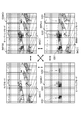
Classifications
-
- G—PHYSICS
- G01—MEASURING; TESTING
- G01J—MEASUREMENT OF INTENSITY, VELOCITY, SPECTRAL CONTENT, POLARISATION, PHASE OR PULSE CHARACTERISTICS OF INFRARED, VISIBLE OR ULTRAVIOLET LIGHT; COLORIMETRY; RADIATION PYROMETRY
- G01J3/00—Spectrometry; Spectrophotometry; Monochromators; Measuring colours
- G01J3/28—Investigating the spectrum
- G01J3/42—Absorption spectrometry; Double beam spectrometry; Flicker spectrometry; Reflection spectrometry
-
- G—PHYSICS
- G01—MEASURING; TESTING
- G01J—MEASUREMENT OF INTENSITY, VELOCITY, SPECTRAL CONTENT, POLARISATION, PHASE OR PULSE CHARACTERISTICS OF INFRARED, VISIBLE OR ULTRAVIOLET LIGHT; COLORIMETRY; RADIATION PYROMETRY
- G01J3/00—Spectrometry; Spectrophotometry; Monochromators; Measuring colours
- G01J3/28—Investigating the spectrum
- G01J3/42—Absorption spectrometry; Double beam spectrometry; Flicker spectrometry; Reflection spectrometry
- G01J3/433—Modulation spectrometry; Derivative spectrometry
-
- G—PHYSICS
- G01—MEASURING; TESTING
- G01M—TESTING STATIC OR DYNAMIC BALANCE OF MACHINES OR STRUCTURES; TESTING OF STRUCTURES OR APPARATUS, NOT OTHERWISE PROVIDED FOR
- G01M3/00—Investigating fluid-tightness of structures
- G01M3/02—Investigating fluid-tightness of structures by using fluid or vacuum
- G01M3/04—Investigating fluid-tightness of structures by using fluid or vacuum by detecting the presence of fluid at the leakage point
- G01M3/20—Investigating fluid-tightness of structures by using fluid or vacuum by detecting the presence of fluid at the leakage point using special tracer materials, e.g. dye, fluorescent material, radioactive material
- G01M3/22—Investigating fluid-tightness of structures by using fluid or vacuum by detecting the presence of fluid at the leakage point using special tracer materials, e.g. dye, fluorescent material, radioactive material for pipes, cables or tubes; for pipe joints or seals; for valves; for welds; for containers, e.g. radiators
-
- G—PHYSICS
- G01—MEASURING; TESTING
- G01M—TESTING STATIC OR DYNAMIC BALANCE OF MACHINES OR STRUCTURES; TESTING OF STRUCTURES OR APPARATUS, NOT OTHERWISE PROVIDED FOR
- G01M3/00—Investigating fluid-tightness of structures
- G01M3/38—Investigating fluid-tightness of structures by using light
-
- G—PHYSICS
- G01—MEASURING; TESTING
- G01N—INVESTIGATING OR ANALYSING MATERIALS BY DETERMINING THEIR CHEMICAL OR PHYSICAL PROPERTIES
- G01N21/00—Investigating or analysing materials by the use of optical means, i.e. using sub-millimetre waves, infrared, visible or ultraviolet light
- G01N21/17—Systems in which incident light is modified in accordance with the properties of the material investigated
- G01N21/25—Colour; Spectral properties, i.e. comparison of effect of material on the light at two or more different wavelengths or wavelength bands
- G01N21/31—Investigating relative effect of material at wavelengths characteristic of specific elements or molecules, e.g. atomic absorption spectrometry
- G01N21/35—Investigating relative effect of material at wavelengths characteristic of specific elements or molecules, e.g. atomic absorption spectrometry using infrared light
- G01N21/3504—Investigating relative effect of material at wavelengths characteristic of specific elements or molecules, e.g. atomic absorption spectrometry using infrared light for analysing gases, e.g. multi-gas analysis
-
- G—PHYSICS
- G01—MEASURING; TESTING
- G01N—INVESTIGATING OR ANALYSING MATERIALS BY DETERMINING THEIR CHEMICAL OR PHYSICAL PROPERTIES
- G01N21/00—Investigating or analysing materials by the use of optical means, i.e. using sub-millimetre waves, infrared, visible or ultraviolet light
- G01N21/17—Systems in which incident light is modified in accordance with the properties of the material investigated
- G01N21/25—Colour; Spectral properties, i.e. comparison of effect of material on the light at two or more different wavelengths or wavelength bands
- G01N21/31—Investigating relative effect of material at wavelengths characteristic of specific elements or molecules, e.g. atomic absorption spectrometry
- G01N21/39—Investigating relative effect of material at wavelengths characteristic of specific elements or molecules, e.g. atomic absorption spectrometry using tunable lasers
-
- G—PHYSICS
- G06—COMPUTING OR CALCULATING; COUNTING
- G06T—IMAGE DATA PROCESSING OR GENERATION, IN GENERAL
- G06T5/00—Image enhancement or restoration
- G06T5/50—Image enhancement or restoration using two or more images, e.g. averaging or subtraction
-
- G—PHYSICS
- G06—COMPUTING OR CALCULATING; COUNTING
- G06T—IMAGE DATA PROCESSING OR GENERATION, IN GENERAL
- G06T7/00—Image analysis
- G06T7/70—Determining position or orientation of objects or cameras
- G06T7/73—Determining position or orientation of objects or cameras using feature-based methods
-
- G—PHYSICS
- G01—MEASURING; TESTING
- G01J—MEASUREMENT OF INTENSITY, VELOCITY, SPECTRAL CONTENT, POLARISATION, PHASE OR PULSE CHARACTERISTICS OF INFRARED, VISIBLE OR ULTRAVIOLET LIGHT; COLORIMETRY; RADIATION PYROMETRY
- G01J3/00—Spectrometry; Spectrophotometry; Monochromators; Measuring colours
- G01J3/28—Investigating the spectrum
- G01J3/42—Absorption spectrometry; Double beam spectrometry; Flicker spectrometry; Reflection spectrometry
- G01J2003/423—Spectral arrangements using lasers, e.g. tunable
-
- G—PHYSICS
- G01—MEASURING; TESTING
- G01N—INVESTIGATING OR ANALYSING MATERIALS BY DETERMINING THEIR CHEMICAL OR PHYSICAL PROPERTIES
- G01N21/00—Investigating or analysing materials by the use of optical means, i.e. using sub-millimetre waves, infrared, visible or ultraviolet light
- G01N21/17—Systems in which incident light is modified in accordance with the properties of the material investigated
- G01N21/25—Colour; Spectral properties, i.e. comparison of effect of material on the light at two or more different wavelengths or wavelength bands
- G01N21/31—Investigating relative effect of material at wavelengths characteristic of specific elements or molecules, e.g. atomic absorption spectrometry
- G01N21/35—Investigating relative effect of material at wavelengths characteristic of specific elements or molecules, e.g. atomic absorption spectrometry using infrared light
- G01N21/3504—Investigating relative effect of material at wavelengths characteristic of specific elements or molecules, e.g. atomic absorption spectrometry using infrared light for analysing gases, e.g. multi-gas analysis
- G01N2021/3513—Open path with an instrumental source
-
- G—PHYSICS
- G01—MEASURING; TESTING
- G01N—INVESTIGATING OR ANALYSING MATERIALS BY DETERMINING THEIR CHEMICAL OR PHYSICAL PROPERTIES
- G01N21/00—Investigating or analysing materials by the use of optical means, i.e. using sub-millimetre waves, infrared, visible or ultraviolet light
- G01N21/17—Systems in which incident light is modified in accordance with the properties of the material investigated
- G01N21/25—Colour; Spectral properties, i.e. comparison of effect of material on the light at two or more different wavelengths or wavelength bands
- G01N21/31—Investigating relative effect of material at wavelengths characteristic of specific elements or molecules, e.g. atomic absorption spectrometry
- G01N21/39—Investigating relative effect of material at wavelengths characteristic of specific elements or molecules, e.g. atomic absorption spectrometry using tunable lasers
- G01N2021/396—Type of laser source
- G01N2021/399—Diode laser
-
- G—PHYSICS
- G06—COMPUTING OR CALCULATING; COUNTING
- G06T—IMAGE DATA PROCESSING OR GENERATION, IN GENERAL
- G06T2207/00—Indexing scheme for image analysis or image enhancement
- G06T2207/20—Special algorithmic details
- G06T2207/20212—Image combination
- G06T2207/20221—Image fusion; Image merging
Definitions
- the present disclosure relates to a substance detection device and a substance detection method for detecting a substance in an area to be detected.
- a gas detection apparatus for performing gas detection at a predetermined point for example, see Patent Document 1 .
- the gas detector emits laser light from an LD (Laser Diode) module.
- the emitted laser light passes through the gas and is reflected by the reflector, and the reflected light is input to a PD (Photo Diode) through a condenser lens and converted into an electrical signal in the PD.
- This electrical signal is used for gas detection.
- the present disclosure is devised in view of the above-described conventional circumstances, and a substance detection device that achieves both suppression of deterioration in detection accuracy of a substance present in a detection area and early detection of a substance present in a detection area Provide a substance detection method.
- the present disclosure is a substance detection device that holds a visible light image of a detection area of a substance, and a projection unit that wavelength-modulates first invisible light in the detection area and emits the light in the horizontal direction and the vertical direction;
- a light receiving section for receiving the second non-visible light transmitted through the substance by the first non-visible light and reflected by the reflector in the background; and in the projection area in the detection area
- the detection based on an actuator for changing the first non-visible light emission direction and the second non-visible light reception direction in the light receiving unit, and the signal intensity frequency characteristic of the second non-visible light
- a detection processing unit that generates a substance position image indicating the detection result of the presence or absence of the substance in the area, wherein the detection processing unit configures one frame of the visible light image and the substance position image : An integer of 2 or more) x n (n)
- a substance detection device which calculates a representative value indicating the detection result of one pixel of two or more integers, and displays the calculation result on
- the present disclosure is a substance detection method using a substance detection device that holds a visible light image of a detection area of a substance, in which the first invisible light is wavelength-modulated in the detection area to horizontally and vertically Emitting the first non-visible light through the substance and receiving the second non-visible light reflected by the background reflector in the detection area; Generating a substance position image indicating the detection result of the presence or absence of the substance in the detection area based on the signal intensity frequency characteristic of the invisible light; and emitting the first invisible light in the detection area Changing the direction and the light receiving direction of the second non-visible light, and m (m: integer of 2 or more) x n (n: 2 or more) constituting one frame of the visible light image and the substance position image (Integer of) of the above detection results of 1 pixel
- the be representative value is calculated each have a step of displaying the results thereof calculated on the monitor superimposed on the corresponding pixels of the visible light image, and Provide a substance detection method.
- Schematic diagram for explaining the outline of the gas detection camera according to the present embodiment Schematic diagram showing an example of the internal configuration of a gas detection camera
- Block diagram showing the hardware configuration example of the gas detection camera in detail
- a block diagram showing in detail an example of the hardware configuration of the light reception processing unit Explanatory drawing which shows the example of the relationship between the wavelength of emitted light, and light reception voltage Explanatory drawing which shows the time change example of the wavelength characteristic of the laser beam by which wavelength modulation was carried out, the characteristic of the light reception level of each reflected light when there is no methane gas, and when methane gas exists.
- Explanatory drawing which shows typically the beam diameter of the laser beam corresponding to m * n each pixel which comprises 1 flame
- Explanatory drawing which shows typically the detection object area
- Pattern explanatory drawing which shows the 1st example of the scan pattern of the laser beam which gave offset of predetermined amount to the perpendicular direction Flow chart showing an example of gas detection operation corresponding to the scan pattern shown in FIG. 13
- Pattern explanatory drawing which shows the 1st example of the scanning pattern of the laser beam which repeats a horizontal high-speed scan and a vertical high-speed scan alternately by every frame
- a pattern diagram showing a second example of a scan pattern of laser light alternately repeating horizontal high-speed scan and vertical high-speed scan every frame 16 is a flowchart showing an example of the gas detection operation corresponding to the scan pattern shown in FIG.
- Explanatory drawing which shows the example of judgment of horizontal high-speed scan based on user operation
- Explanatory drawing which shows the example of judgment of vertical high-speed scan based on user operation
- a diagram showing a second example of a UI screen displaying an overlay image in which a gas position image is superimposed on a visible light image Explanatory drawing which shows the example of switching of the display mode of the image displayed on UI screen
- the present embodiment which specifically discloses a substance detection device and a substance detection method according to the present disclosure will be described in detail with reference to the drawings as appropriate. However, the detailed description may be omitted if necessary. For example, detailed description of already well-known matters and redundant description of substantially the same configuration may be omitted. This is to avoid unnecessary redundancy in the following description and to facilitate understanding by those skilled in the art. It is to be understood that the attached drawings and the following description are provided to enable those skilled in the art to fully understand the present disclosure, and they are not intended to limit the claimed subject matter.
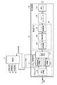
- FIG. 1 is a schematic view illustrating an outline of a gas detection camera 1 according to the present embodiment.
- the gas detection camera 1 (an example of the substance detection device) is configured to include a visible light camera VSC and a non-visible light sensor NVSS arranged in the housing 1z.
- the gas detection camera 1 including at least the non-visible light sensor NVSS will be described as an example of the substance detection device according to the present disclosure.
- the x-axis is defined in the direction in which the imaging lens 31 of the visible light camera VSC and the condenser lens CLZ of the invisible light sensor NVSS are disposed so as to be exposed with respect to the housing 1z.
- the y axis is defined in the horizontal direction in a horizontal direction
- the z axis is defined in the direction perpendicular to the x axis and the y axis and in the vertical direction (in other words, the gravity direction).
- the visible light camera VSC is, for example, a person HM existing in a predetermined detection space K using reflected light RM of visible light having a predetermined wavelength (for example, 0.4 to 0.7 ⁇ m) as in the existing surveillance camera. And image an object (not shown).
- An image captured by the visible light camera VSC is referred to as a "visible light image”.
- the non-visible light sensor NVSS is a laser that is non-visible light (for example, infrared light, an example of the first non-visible light) wavelength-modulated around a predetermined wavelength in the same detection space K as the visible light camera VSC.
- the laser beam LS is light including a wavelength of an absorption wavelength band of a substance to be detected (for example, gas GS).
- the non-visible light sensor NVSS is a laser reflected light RV (an example of the second non-visible light) in which the laser light LS is transmitted through the substance to be detected (for example, gas GS which is a gas such as methane gas) and reflected by the background reflector. That is, the presence or absence of detection of the gas GS in the detection space K is received based on the signal intensity frequency characteristics of the laser reflected light RV by receiving the laser reflected light in which the component of the specific wavelength is partially absorbed by the substance to be detected. judge.
- the substance to be detected for example, gas GS which is a gas such as methane gas
- the substance to be detected by the non-visible light sensor NVSS is a substance that is difficult to visually recognize in the visible light image captured by the visible light camera VSC, and in addition to gas such as gas GS, liquid or It may be solid.
- gas GS gas GS
- the case where the substance to be detected is the gas GS is illustrated.
- the gas detection camera 1 is an image (hereinafter referred to as “gas position”) which visually shows the detection result of the presence or absence of the gas GS determined by the invisible light sensor NVSS on the visible light image captured by the visible light camera VSC. Or an information (for example, the name of the detected gas GS) on the gas position image is superimposed and transmitted to be generated and displayed on the monitor 150.
- the output destination of the overlay image from the gas detection camera 1 is an externally connected device connected to the gas detection camera 1 via a network (not shown), and is, for example, the camera server CS or the monitor 150 of FIG.
- a substance detection system is configured to include the gas detection camera 1 and the monitor 150.
- the network may be a wired network (for example, an intranet, the Internet) or a wireless network (for example, a wireless local area network (LAN)).
- FIG. 2 is a schematic view showing an example of the internal configuration of the gas detection camera 1.
- FIG. 2 shows an internal configuration of the gas detection camera 1 as viewed from above in FIG. 1 (that is, downward in the z-axis direction).
- the gas detection camera 1 has, for example, a box-shaped casing 1z.
- An opening 1 w for the invisible light sensor NVSS is formed on the front surface (the positive direction of the x axis) of the housing 1 z.
- the scan angle of view in the two-dimensional scan of the laser beam LS emitted (projected) from the laser diode LD is determined by the size of the opening 1 w.
- transparent glass or resin may be inserted into the opening 1 w for waterproof and dustproof.
- the imaging lens 31 (see FIG. 3) of the visible light camera VSC is exposed on the front surface (the positive direction of the x axis) of the housing 1z.
- a pan and tilt unit 15 (an example of an actuator) is provided inside the housing 1z.
- the pan-tilt unit 5 is placed on a camera platform (not shown), and is represented by a pan direction (direction along xy plane in FIG. 2) represented by arrow P in FIG. 2 and arrow T in FIG. It is pivotable in the tilt direction (z-axis direction in FIG. 2).
- the pan and tilt unit 15 includes a motor mechanism (not shown) for driving the camera platform.
- a laser diode LD, a projection light source optical unit PLZ (for example, a collimating lens), a photodiode PD, and a condensing lens CLZ are mounted on the pan head.
- the pan and tilt unit 15 can two-dimensionally scan (horizontal scan and vertical scan) in the detection space K with the laser light LS emitted from the laser diode LD by pivoting the camera platform in the pan direction and the tilt direction. is there.
- the laser light LS emitted from the laser diode LD is transmitted through the projection light source optical unit PLZ to be collimated light and emitted toward the detection space K.
- the laser reflected light RV in which the component of the specific wavelength is partially absorbed by the gas GS in the detection space K is incident through the opening 1 w formed in the housing 1 z of the gas detection camera 1, and the condensing lens CLZ
- the light is collected by the light source and received by the photodiode PD.
- Signal intensity frequency characteristics of the laser reflected light RV received by the photodiode PD (specifically, a characteristic indicating whether or not the waveform indicating the signal intensity of the laser reflected light RV has a frequency 2f twice as high as the modulation frequency f
- the presence or absence of the gas GS present in the detection space K is determined.
- the detection space K is set, for example, by the shape of the opening 1 w formed in the housing 1 z, and corresponds to a range (scan angle of view) in which the laser light LS can scan in the detection space K.
- the laser diode LD is susceptible to temperature, and the wavelength of the laser beam LS emitted from the laser diode LD is shifted due to a slight temperature change. Therefore, the invisible light sensor NVSS is a laser beam LS emitted from the laser diode LD so that the wavelength of the laser beam LS (more specifically, the central wavelength in wavelength modulation) does not change during the detection operation of the gas GS. Temperature control (control for temperature control) may be performed to keep the temperature of
- a diffusion plate (not shown) is disposed in the vicinity of the opening 1 w in the housing 1 z. Further, a reference cell (not shown) is disposed between the diffusion plate and the laser diode LD. The reference cell is filled with a gas having the same composition as the gas GS (eg, methane gas).
- the temperature control when the laser beam LS emitted from the laser diode LD passes through the reference cell and is diffused by the diffusion plate, a part of the diffused light passes through the condenser lens CLZ to detect a substance The light is received by the photodiode PD. Further, since the laser beam LS is diffused by the diffusion plate, the light amount of the laser reflected light RV received by the photodiode PD is reduced, and falls within the range of the allowable light reception amount of the photodiode PD. In the case where the temperature control control is not performed, the arrangement of the diffusion plate or the reference cell may be omitted.
- FIG. 3 is a block diagram showing an example of the hardware configuration of the gas detection camera 1 in detail.
- the gas detection camera 1 is configured to include the non-visible light sensor NVSS and the visible light camera VSC.
- the non-visible light sensor NVSS is configured to include the control unit 11, the projection unit PJ, and the light reception processing unit SA.
- the control unit 11 is configured using, for example, a central processing unit (CPU), a micro processing unit (MPU), or a digital signal processor (DSP).
- the control unit 11 performs, for example, signal processing for totally controlling the operation control of each part of the invisible light sensor NVSS, input / output processing of data between the other parts, arithmetic processing of data, and storage processing of data. Do. Further, the control unit 11 sets a detection threshold M for detecting the gas GS to be detected by the non-visible light sensor NVSS in the detection processing unit 27.
- the control unit 11 sends a timing signal for AD conversion to the detection processing unit 27.
- the control unit 11 modulates the wavelength of the laser light LS emitted from the laser diode LD (for example, sweeps it within ⁇ predetermined width (for example, ⁇ 0. 0.5 nm) from the center frequency, see FIG. 5)
- the light source light emission signal of is sent to the laser diode LD.
- the control unit 11 receives a temperature control state signal from the detection processing unit 27, generates a temperature control signal based on the temperature control state signal, and sends the temperature control signal to the laser diode LD.
- the temperature adjustment control signal is a signal for adjusting the temperature of the laser light LS emitted from the laser diode LD, and is a signal instructing heat absorption or heat generation to a Peltier element (not shown) of the laser diode LD.
- the laser diode LD changes the central wavelength of the wavelength of the laser light LS according to the change in temperature according to the temperature control signal from the control unit 11.
- the control unit 11 refers to setting information (for example, information such as at which timing the emission direction of the laser beam LS or the light reception direction of the laser reflected light RV is switched) stored in the memory 13 (for example, semiconductor memory)
- a PTU (Pan Tilt Unit) control signal for controlling the drive of the pan and tilt unit 15 is generated and sent to the pan and tilt unit 15.
- the projection unit PJ constitutes a part of the pan and tilt unit 15, and includes a laser diode LD and a projection light source optical unit PLZ.
- the laser diode LD emits the laser light LS whose wavelength is adjusted so that the wavelength of the laser light LS matches the peak of the absorption wavelength band of the gas GS which is the detection target.
- a gas GS is a substance to be detected, given as an example methane gas (CH 4).
- the control unit 11 modulates the wavelength of the laser beam LS emitted from the laser diode LD by modulating the drive current of the laser diode LD as a semiconductor diode.
- the drive current is an input signal of the semiconductor diode, and the frequency corresponding to the alternating current of the drive current is the modulation frequency.
- a Peltier element (not shown) provided in the laser diode LD absorbs or generates heat in accordance with the temperature adjustment control signal from the control unit 11, and fluctuates the temperature of the laser diode LD, thereby centering the central wavelength of the wavelength of the laser light LS. adjust.
- the projection light source optical unit PLZ is configured using, for example, a collimator lens, and converts the laser light LS emitted from the laser diode LD into parallel light.
- the pan and tilt unit 15 pivots the camera platform on which the laser diode LD, the projection light source optical unit PLZ (for example, a collimating lens), the condenser lens CLZ, and the photodiode PD are mounted in the pan direction and the tilt direction.
- the pan and tilt unit 15 two-dimensionally scans within the scanning range of the detection space K by the laser light LS emitted from the laser diode LD.
- FIG. 4 is a block diagram showing in detail an example of the hardware configuration of the light reception processing unit.
- the light reception processing unit SA includes a condenser lens CLZ, a photodiode PD, a signal processing unit 26, a detection processing unit 27, and a display processing unit 28.
- the signal processing unit 26 includes an I / V conversion circuit 261, an amplification circuit 262, and a filter processing circuit 263.
- the detection processing unit 27 includes an AD conversion circuit 271, a temperature adjustment control processing unit 272, and a substance detection processing unit 273.
- the laser beam LS passes through the gas GS at any time while the laser beam LS wavelength-modulated to the detection space K is projected (irradiated) in the main scanning direction (see later) from the projection unit PJ.
- the reflector is, for example, a pipe or a valve disposed in the detection space K, or a wall, floor or ceiling of the detection space K.
- the temperature adjustment control processing unit 272, the substance detection processing unit 273, and the display processing unit 28 of the detection processing unit 27 are realized by the processor 20 executing the program stored in the memory 13. Also, the signal processing unit 26 and the AD conversion circuit 271 of the detection processing unit 27 may be similarly realized by the processor 20 executing the program held in the memory 13.
- the condensing lens CLZ is emitted from the laser diode LD, receives the laser reflected light RV in which a component of a specific wavelength is partially absorbed by the gas GS in the detection space K, and condenses it on the photodiode PD.
- the photodiode PD generates a charge according to the light amount of the laser reflected light RV received by the condensing lens CLZ, and outputs it as a current signal.
- the I / V conversion circuit 261 converts the current signal output from the photodiode PD into a voltage signal.
- the amplification circuit 262 amplifies the voltage signal output from the I / V conversion circuit 261.
- the filter processing circuit 263 filters the voltage signal amplified by the amplifier circuit 262 and outputs the filtered voltage signal to the AD conversion circuit 271 as a signal used for gas detection.
- the AD conversion circuit 271 converts the signal input from the signal processing unit 26 into a digital signal when detecting the gas GS or adjusting the temperature of the laser diode LD.
- the temperature adjustment control processing unit 272 generates a signal (temperature adjustment state signal) representing the temperature adjustment state based on the value converted into the digital value by the AD conversion circuit 271 in the temperature adjustment operation, and outputs the signal to the control unit 11 .
- This temperature control state signal is a signal indicating the magnitude (signal level) of a signal having a frequency (2 f) that is twice that of the signal (frequency f) of the wavelength-modulated laser beam LS emitted from the laser diode LD. It is.
- the temperature control state signal is twice the frequency f
- the temperature control state signal becomes a signal whose frequency fluctuates.
- the magnitude (signal level) of the signal of the frequency (2f) which is twice that of the frequency f obtained based on the signal from the photodiode PD is reduced.
- the substance detection processing unit 273 detects the presence or absence of the gas GS based on the value converted into the digital value by the AD conversion circuit 271 in the detection operation of the gas GS (see FIGS. 5 and 6). And a signal indicating the detection result of the presence or absence of the gas GS to the display processing unit 28.
- the substance detection processing unit 273 detects the presence or absence of the gas GS for each pixel constituting the gas position image (see below), and outputs a signal indicating the detection result of the presence or absence of the gas GS to the display processing unit 28. Do. Thereby, the display processing unit 28 can generate a gas position image indicating the detection result of the presence or absence of the gas GS for each pixel.
- the non-visible light sensor NVSS detects the presence or absence of the gas GS for each pixel in one line or gas position image in the horizontal or vertical direction that forms a gas position image (see below) (see below)
- the gas position image can be output to the monitor 150 earlier via the visible light camera VSC, as compared to the case where the gas position image is generated collectively for each frame. That is, the user who monitors the detection space K can quickly grasp whether or not there is a generation point of the gas GS in the detection space K.
- the substance detection processing unit 273 collects signals indicating the detection result of the presence or absence of the gas GS for each pixel for each line in the horizontal direction or the vertical direction that constitutes a gas position image (see below). It may be output to the display processing unit 28. In addition, the substance detection processing unit 273 collectively outputs a signal indicating the detection result of the presence or absence of the gas GS for each pixel in one frame of the entire gas position image (see below) and outputs the signal to the display processing unit 28. It is also good.
- the substance detection processing unit 273 is a signal of the wavelength-modulated laser light LS emitted from the laser diode LD based on the value converted into the digital value by the AD conversion circuit 271 as in the temperature control state signal.
- a signal indicating the magnitude (signal level) of the signal of the frequency (2f) that is twice that of (frequency 1f) is obtained.
- the substance detection processing unit 273 generates a signal indicating the detection result of the presence or absence of the gas GS based on whether or not a signal indicating the magnitude (signal level) of the signal of the double frequency (2f) is obtained. .
- the display processing unit 28 (an example of the detection processing unit) generates, from the non-visible light sensor NVSS, a gas position image that visually indicates the detection result (for example, a two-dimensional position) of the presence or absence of the gas GS in the detection space K .
- the display processing unit 28 uses a signal output each time from the substance detection processing unit 273 (that is, a signal indicating the detection result of the presence or absence of the gas GS for each pixel constituting the gas position image).
- a gas position image for each pixel is generated and output to the display control unit 37 of the visible light camera VSC.
- the display processing unit 28 when the display processing unit 28 outputs a signal for one line (that is, one line in the horizontal or main scanning direction to which the laser light LS is irradiated) from the substance detection processing unit 273. May generate a gas position image corresponding to the signal for one line and output it to the display control unit 37 of the visible light camera VSC.
- the display processing unit 28 when the signal for one frame (that is, one frame of the gas position image) is output from the substance detection processing unit 273, the display processing unit 28 outputs the gas position image corresponding to the signal for the one frame. It may be generated and output to the display control unit 37 of the visible light camera VSC.
- the gas position image is image data indicating the detection result of the presence or absence of the gas GS in the scan angle of view of the pan and tilt unit 15, and data of two-dimensional position information (for example, pan angle and tilt angle of camera platform) in the detection space K And.
- the display processing unit 28 outputs the gas position image to the display control unit 37 of the visible light camera VSC.
- the invisible light sensor NVSS provides the user with a visual sense of where in the detection space K the inside of the angle of view of the gas detection camera 1 (in other words, the scan angle of view of the pan and tilt unit 15) is present.
- the user is, for example, a manager of a gas company that dispatches an investigator of a gas company to the installation location of the gas detection camera 1 (for example, a piping room of a building, see FIG. 17). It is a person who monitors the generation position of the gas GS with a monitoring monitor (for example, a monitor 150 described later) or the like for the display data (see later described).
- the display processing unit 28 transmits a gas position image to the display control unit 37 in the visible light camera VSC, for example, a monitor 150, a camera server CS, and a communication terminal (not shown). For example, it may be transmitted to a smartphone or a tablet terminal owned by the user.
- the visible light camera VSC includes an imaging lens 31, an image sensor 33, a signal processing unit 35, a display control unit 37, and an output unit 38.
- the signal processing unit 35 and the display control unit 37 are realized by the processor 41 executing the program held in the memory 39.
- the imaging lens 31 has an imaging angle of view that generally includes the scanning angle of view of the pan-tilt unit 15 of the non-visible light sensor NVSS, and condenses incident light from the outside (that is, reflected light RM). Image on the imaging plane of
- the image sensor 33 has a peak of spectral sensitivity to the wavelength of visible light (for example, 0.4 ⁇ m to 0.7 ⁇ m).
- the image sensor 33 converts the optical image formed on the imaging surface into an electrical signal.
- the output of the image sensor 33 is input to the signal processing unit 35 as an electrical signal.
- the signal processing unit 35 generates a visible light image defined by, for example, RGB (Red Green Blue) or YUV (brightness and color difference) using an electric signal output from the image sensor 33. Thereby, a visible light image captured by the visible light camera VSC is formed. The signal processing unit 35 outputs the visible light image to the display control unit 37.
- the display control unit 37 detects the visible light image output from the signal processing unit 35 and the gas position image output from the display processing unit 28 when, for example, the gas GS is detected at a predetermined position in the visible light image. By superimposing and combining, display data (for example, an overlay image) is generated.
- the display control unit 37 may read and obtain a visible light image from the memory 39. According to the overlay image, the user specifies the location where the gas GS is generated in the visible light image captured by the visible light camera VSC by specifically connecting the object (for example, piping) shown in the visible light image. Yes, it is possible to find out the location of the gas GS early.
- the output unit 38 generates the UI screen WD1 (see FIGS. 17 and 18) including the display data (for example, overlay image) generated by the display control unit 37 and outputs the UI screen WD1 to an external device (for example, camera server CS and monitor 150) Do.
- the display data generated by the display control unit 37 is not limited to the overlay image, and a heat map image in which the visible light image is not shown (ie, display The gas position image itself (see heat map mode) sent from the processing unit 28 may be used, or the visible light image itself (see camera mode) may be used.
- the overlay image is limited to an image (see, for example, the overlay mode on the upper right of FIG.
- the overlay image is an image in which a local gas position image corresponding to only the pixel in which the gas GS is detected among all the pixels constituting the visible light image is superimposed (for example, detection in the lower right of FIG. See overlay mode).
- the camera server CS transmits display data (for example, overlay image) output from the display control unit 37 to a communication terminal (not shown) or one or more externally connected devices (not shown), and the communication terminal or one or more To prompt display of display data on the display screen of the externally connected device.
- display data for example, overlay image
- the monitor 150 is configured by using, for example, an LCD (Liquid Crystal Display) or an organic EL (Electroluminescence), and displays the display data output from the display control unit 37.
- the monitor 150 of the present embodiment may be configured using a touch panel that can receive an input operation (touch operation) of the user.
- an operation signal based on the input operation is, for example, a control unit of the gas detection camera 1 via a network (not shown). It is input to 11.
- the control unit 11 may determine, for example, the main scanning direction and the sub-scanning direction (see later) of the laser beam LS according to the operation signal.
- FIG. 5 is an explanatory view showing an example of the relationship between the wavelength of the emitted light and the light receiving voltage.
- methane gas CH 4
- the vertical axis in FIG. 5 represents the light receiving voltage (in which the unit is a normalized value) of the photodiode PD
- the horizontal axis in FIG. 5 represents the wavelength (nm: nanometer) of the laser reflected light RV received by the photodiode PD.
- the gas GS is present at a position where the absorption rate is high.
- the absorption characteristics of the gas GS are determined for each gas GS.
- the absorption spectrum of the gas GS has, for example, a wavelength band centered at 1653.67 nm.
- the laser beam LS emitted from the laser diode LD is modulated with a modulation width of 0.05 nm with the central wavelength of 165.67 nm as shown in the wavelength modulation range WAR0.
- the laser beam LS (that is, incident light whose wavelength is modulated) is emitted from the laser diode LD.
- the laser reflected light RV (that is, the received reflected light) in which the component of the specific wavelength is partially absorbed by the gas GS in the detection space K is the signal frequency (f1: modulation) of the laser light LS by the photodiode PD.
- the frequency (2f1) is twice that of the frequency (2f1). In this case, a sine wave signal having a constant frequency is output.
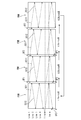
- FIG. 6 is an explanatory view showing a time change example of the wavelength characteristic of the wavelength-modulated laser light LS, and the characteristic of the light reception level of each reflected light when there is no methane gas and when there is a methane gas.
- the topmost wavelength modulation (f1) shows the wavelength characteristic of the output of the laser diode LD (that is, the laser light LS)
- the vertical axis shows the wavelength
- the horizontal axis shows time.
- the middle and lowermost light reception levels indicate signals (specifically, voltages) output from the photodiode PD in the absence and presence of methane gas, respectively.
- the signal received by the photodiode PD has a frequency (2f1) twice that of the modulation frequency (f1) of the laser light LS emitted from the laser diode LD when the gas GS is present. Therefore, the substance detection processing unit 273 detects the presence or absence of the gas GS based on the output signal of the AD conversion circuit 271 in the waveform of the output signal and has a signal of the frequency (2f1) twice the modulation frequency (f1). Determine if the property can be seen.
- the laser light LS emitted from the laser diode LD is a signal received by the photodiode PD, the laser emitted from the laser diode LD
- the doubled frequency (2f1) is 0 (zero) with respect to the modulation frequency (f1) of the light LS.
- the laser light LS is emitted after being wavelength-modulated by the modulation frequency f1 of a very large value.
- the wavelength modulation speed corresponding to the modulation frequency f1 (that is, the speed for sweeping the wavelength in the range of ⁇ 0.05 nm from the central wavelength) is a very large value, and compared to the scan speed of the pan tilt unit 15 described later. It is a fairly large value. Therefore, when emitting the laser light LS, the gas detection camera 1 needs to emit the light after wavelength-modulating the laser light LS at the modulation frequency f1 in a very short time.
- the gas detection camera 1 performs high-speed scanning in either the horizontal direction or the vertical direction in order to early determine whether the gas GS is present in the detection space K. This is to detect the presence or absence of the gas GS based on the wavelength characteristic of the received laser reflected light RV.
- the beam diameter of the laser beam LS is considerably larger than the length of one pixel of the gas position image for the purpose of detecting even when the gas GS which is the detection target of the gas detection camera 1 is present at a minimum. Small (see Figure 7).
- the gas detection camera 1 detects one pixel portion of the gas position image described later, the gas GS at one point in that one pixel
- the laser light LS which is wavelength-modulated by a number of multiple periods is irradiated to the one point.
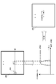
- FIG. 7 is an explanatory view schematically showing the beam diameter BRD of the laser light LS corresponding to m ⁇ n pixels forming one frame FRM of the gas position image.
- FIG. 8 is an explanatory diagram of the gas detection level in the first pixel IME in the m-th row and the n-th column. Both m and n are integers of 2 or more, m corresponds to the number of columns constituting one frame FRM, and n corresponds to the number of rows constituting one frame FRM.
- One frame FRM of the gas position image generated by the display processing unit 28 includes, for example, m ⁇ n pixels (that is, one pixel IME).
- the pixel in the n-th row in the m-th column is conveniently described as the “mn” or “mn” pixel.
- FIG. 7 exemplifies one pixel IME of “4-3” (that is, one pixel IME in the third row and the third row in the fourth column).
- the gas detection camera 1 according to the present embodiment generates the gas position image of the one-pixel IME by driving the pan and tilt unit 15 so that the laser light LS wavelength-modulated in the horizontal direction and the vertical direction (that is, FIG.
- the beam is irradiated at high speed with a beam diameter BRD in the direction from the left side to the right side of the drawing (see the lower left of the drawing in FIG. 7).
- the gas detection camera 1 has a direction in which the laser light LS is slightly inclined with respect to the pixels in the first row (that is, the pixels “1-1” to the pixels “m ⁇ 1”). The irradiation is performed while scanning in the horizontal and vertical directions so as to be SC1.
- the beam diameter of the wavelength-modulated laser beam LS is very small compared to the lateral length of one pixel IME having a rectangular shape (for example, a square). This is for the purpose of detecting even when the gas GS which is the detection target of the gas detection camera 1 is extremely present, as described in detail above.
- the laser beam LS when the laser beam LS is scanned in the direction SC1 and irradiated, the entire region of one pixel IME of “4-3” is irradiated with the laser beam LS. Rather, the laser beam LS is emitted only to a partial area (detection target area DTAR) having a substantially rectangular shape whose height is the length of the beam diameter BRD. In other words, in one pixel IME, the laser light LS is not irradiated (that is, there is a dead area where it is not determined whether the gas GS is detected).
- the gas detection camera 1 detects the presence or absence of the gas GS at an early stage, and pan and tilt so that the gas detection camera 1 irradiates the laser light LS to the entire area in one pixel IME.
- the drive of the unit 15 it takes time for the control.
- the gas detection camera 1 sets the maximum value of the gas detection level (see FIG. 9) of one pixel IME based on the wavelength characteristic of the laser reflected light RV when the laser light LS is irradiated in the direction SC1. It is calculated as a representative value of the detection result of the gas GS in the pixel IME (see the lower right of FIG. 8).
- a gas detection level (an example of a substance detection level) is, for example, in units of ppm-m (meters), and is obtained by the substance detection processing unit 273 from the light reception voltage based on a predetermined conversion formula.
- ppm-m is a unit indicating the concentration when 1 m of gas GS is present.
- the determination result of the presence or absence of the detection of the gas GS is discrete in the vertical direction.
- the resolution of the human eye for visually recognizing the visible light image on which the gas position image is superimposed is not good as compared with the resolution of a normal camera, for example, the presence or absence of detection of the gas GS only discretely in the vertical direction It is inferred that there is no particular problem in the determination of the presence or absence of the detection of the gas GS, even if it is not determined.
- the horizontal axis is the position of one pixel IME (in other words, the irradiation time of the laser light LS), and the vertical axis is the gas detection level in one pixel IME.
- a is the maximum value of the gas detection level
- b is the minimum value of the gas detection level. Therefore, the gas detection camera 1 calculates the representative value of the gas detection level in the one pixel IME of “mn” to be detected for the presence or absence of the gas GS as the maximum value a.
- FIG. 9 is a comparative explanatory view of the horizontal scan image of the laser light LS, the wavelength characteristics of the wavelength-modulated laser light LS, the signal intensity characteristics of the received laser reflected light RV, and the gas detection level.
- a gas free area NGSAR without gas GS and a gas free area GSAR with gas GS are shown in the detection space K.
- the scanning direction of the laser light LS is shown toward the direction.
- the horizontal axes of the graphs of the second stage to the fourth stage (lowermost stage) in FIG. 9 correspond to the positions of the non-gas area NGSAR and the gas presence area GSAR shown at the top of the figure.
- the vertical axis of the graph of the second stage of FIG. 9 shows the wavelength of the laser light LS
- the vertical axis of the graph of the third stage of the same figure shows the voltage of the laser reflected light RV (received voltage; see FIG. 5).
- the vertical axis of the fourth graph indicates the gas detection level.
- the gas detection level is calculated for each one-pixel IME constituting the gas position image, as described with reference to FIG. In the example of FIG.
- the voltage of the third stage and the gas detection level of the fourth stage in FIG. There is no Specifically, a signal at a frequency (2f1) twice that of the modulation frequency f1 is not detected at the third stage voltage of FIG. 9, and the substance detection processing unit 273 is set at the gas detection level of the fourth stage in FIG. A gas detection level which does not exceed the detected detection threshold M (not shown) is detected.
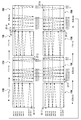
- FIG. 10 is an explanatory view schematically showing a detection target area DTAR of a gas GS and a dead area in each of m ⁇ n pixels constituting one frame FRM of a gas position image.
- FIG. 11 is a flow chart showing an example of the gas detection operation corresponding to the scan pattern shown in FIG.
- One frame FRM of the gas position image shown in FIG. 10 is composed of m ⁇ n one-pixel IMEs (see FIG. 7).
- the gas GS is detected in the detection angle K at the same angle of view as the angle of view when the visible light image is captured by the visible light camera VSC.
- a detection target area DTAR (see FIG. 7) to which the wavelength-modulated laser light LS is irradiated and the laser light LS is not irradiated in each of m ⁇ n 1-pixel IMEs constituting one frame FRM of the gas position image There is a dead zone.
- FIG. 7 A detection target area DTAR (see FIG. 7) to which the wavelength-modulated laser light LS is irradiated and the laser light LS is not irradiated in each of m ⁇ n 1-pixel IMEs constituting one frame FRM of the gas position image There is a dead zone.
- the gas detection camera 1 scans (scans) the laser light LS wavelength-modulated at high speed in the horizontal direction and drives it at low speed in the vertical direction by driving the pan and tilt unit 15. ).
- the wavelength-modulated laser light LS is determined to be the presence or absence of the detection of the gas GS with the detection target area DTAR for m being a total of n lines. Become. Therefore, although only detection of discrete gas GS is performed in the vertical direction, as described above, since the resolution of the human eye is lower than that of a normal camera, the laser is continuously continuous in the horizontal direction. Since the light LS is irradiated, it can be considered that the deterioration of the detection accuracy of the gas GS is suppressed.
- FIG. 10 shows an example in which the laser light LS is irradiated while scanning continuously in the horizontal direction at high speed, and the laser light LS is emitted discretely in the vertical direction. Is the same even if the horizontal direction and the vertical direction are interchanged. That is, although not illustrated in FIG. 10, in one frame FRM of the gas position image, the wavelength-modulated laser light LS is a line of n detection target areas DTAR in total of m lines. The presence or absence of detection may be determined. In this case, only the detection of the discrete gas GS is performed in the horizontal direction, but as described above, since the resolution of the human eye is lower than the resolution of a normal camera, the detection in the vertical direction is performed. Since the laser light LS is continuously irradiated, it can be considered that the deterioration of the detection accuracy of the gas GS is suppressed.
- the gas detection camera 1 emits the wavelength-modulated laser light LS from the projection unit PJ (S1), and controls the drive of the pan and tilt unit 15 based on the PTU control signal from the control unit 11.
- the vertical scan position control of the laser beam LS is started (S2), and the horizontal scan control is started (S3). That is, as shown in FIG. 10, the gas detection camera 1 scans the wavelength-modulated laser light LS slowly at a low speed in the vertical direction and at a high speed in the horizontal direction while capturing the visible light image Irradiate within the same angle of view.
- the gas detection camera 1 receives the laser reflected light RV, which is the reflected light of the laser light LS, by the photodiode PD via the condensing lens CLZ.
- the gas detection camera 1 amplifies the signal output from the photodiode PD in the signal processing unit 26 (S4).
- the gas detection camera 1 detects the gas GS detection process (in other words, gas detection process) based on the signal amplified in step S4 (in other words, the wavelength characteristic of the laser reflected light RV). It is executed in the part 27 (S5).
- the gas detection camera 1 determines whether the gas GS has been detected in step S5 (e.g., the result of determining whether the gas GS is detected per pixel described with reference to FIGS. 8 and 9).
- the processing for generating a gas position image (that is, the gas position image generation processing) is executed in the display processing unit 28 based on (S6).
- the details of the gas position image generation process of step S6 will be described later with reference to
- the gas detection camera 1 determines whether the irradiation position of the laser light LS has reached the end position of the horizontal scan position in the control unit 11 that controls the drive of the pan and tilt unit 15 (in other words, the laser in the horizontal direction) It is determined whether the scanning of the light LS is completed (S7).
- step S7 and step S9 will be briefly described.
- the control unit 11 acquires a drive control amount table (not shown) of the pan and tilt unit 15 stored in advance in the memory 13 and controls the drive of the pan and tilt unit 15 based on the drive control amount table.
- the drive control amount table for example, drive control corresponding to the start position to the end position of the horizontal scan position of the laser beam LS corresponding to the scan angle of view (see FIG. 2) determined for generating the gas position image.
- the amount and the drive control amount corresponding to the start position to the end position of the vertical scan position of the laser beam LS are stored. Therefore, based on the drive control amount table and the current drive control amount of the pan and tilt unit 15, the control unit 11 can determine whether the irradiation position of the laser light LS has reached the end position of the horizontal scan position.
- control unit 11 can determine whether the irradiation position of the laser light LS has reached the end position of the vertical scan position based on the drive control amount table and the current drive control amount of the pan and tilt unit 15 is there.
- the method of determining whether the irradiation position of the laser beam LS has reached the end position of the horizontal scan position or the vertical scan position is not limited to the method using the drive control amount table described above. . Further, this determination method can be applied to the determination methods of step S7A and step S9A shown in FIG.
- step S7 If scanning of the laser beam LS in the horizontal direction is not completed (S7, NO), the processing of the gas detection camera 1 returns to step S4, and steps S4 to S4 until scanning of the laser beam LS in the horizontal direction is completed.
- the process of S6 is repeated. In other words, when the laser beam LS is scanned at high speed in the horizontal direction, for example, the processing in steps S4 to S6 is performed while the laser beam LS is scanned at high speed in the horizontal direction.
- step S8 the gas detection camera 1 determines whether the irradiation position of the laser beam LS has reached the end position of the vertical scan position in the control unit 11 that controls the drive of the pan and tilt unit 15 (in other words, the laser in the vertical direction). It is determined whether the scanning of the light LS is completed (S9).
- step S9 If scanning of the laser light LS in the vertical direction is not completed (S9, NO), the processing of the gas detection camera 1 returns to step S3, and steps S3 to S3 until scanning of the laser light LS in the vertical direction is completed.
- the process of S6 is repeated. In other words, when the laser beam LS is slowly scanned in the vertical direction, for example, the processing in steps S3 to S6 is performed while the laser beam LS is slowly scanned in the vertical direction.
- the gas detection camera 1 determines that the scanning of the laser beam LS in the vertical direction is completed (S9, YES), the scanning of the laser beam LS in the vertical direction is stopped (S10). Thus, the irradiation of the laser light LS for one frame FRM of the gas position image is completed.
- imaging for example, imaging of a visible light image
- the process of the gas detection camera 1 returns to step S2.
- the gas GS detection process does not need to be executed.
- the processing of the detection camera 1 ends.
- FIG. 12 is a flowchart showing an example of the gas position image generation process of step S6 of FIG. 11 in detail.
- the gas position image generation process shown in FIG. 12 is executed, for example, with one pixel forming the gas position image as a processing target pixel.
- the display processing unit 28 sets a processing target pixel (for example, one pixel forming the gas position image) of the gas position image generation process (S6-1).
- the display processing unit 28 acquires (inputs) the gas detection level of the processing target pixel set in step S6-1 based on the output from the detection processing unit 27 (S6-2).
- the display processing unit 28 sets the gas detection level of the processing target pixel in the current frame (current frame) set in step S6-1 and the same corresponding processing target pixel in the frame (previous frame) immediately before the current frame.
- the gas detection level is compared (S6-3). If the display processing unit 28 determines that the gas detection level of the processing target pixel in the current frame is higher than the gas detection level of the same corresponding processing target pixel in the previous frame (S6-3, YES), the gas in the current frame A process of generating a gas position image at the processing target pixel is executed based on the detection level (S6-4).
- the display processing unit 28 determines that the gas detection level of the processing target pixel in the current frame is lower than or equal to the gas detection level of the same corresponding processing target pixel in the previous frame (S6-3, NO), It is determined that the gas position image in the same processing target pixel in the frame is maintained and used (S6-5).
- step S6-4 or step S6-5 the display processing unit 28 determines that the current processing target pixel (that is, the one set in step S6-1) is the laser beam LS in the horizontal direction or the main scanning direction of the gas position image. It is determined whether or not it is the end pixel (final pixel) in the scan of (S6-6). If the display processing unit 28 determines that the current processing target pixel is the end pixel (final pixel) in the scanning (scanning) of the laser beam LS in the horizontal direction or the main scanning direction of the gas position image (S6- 6, YES), the gas position image generation process shown in FIG. 12 is ended. After this, although not shown in FIG.
- the display processing unit 28 outputs the gas position image of one pixel generated or determined to be used in step S6-4 or step S6-5 to the display control unit 37.
- the display control unit 37 superimposes (overlays) the position of the corresponding pixel of the visible light image displayed on the monitor 150 every time the gas position image of one pixel sent from the display processing unit 28 is acquired. Do.
- the display processing unit 28 determines that the current processing target pixel is not the end pixel (final pixel) in the scanning (scanning) of the laser beam LS in the horizontal direction or the main scanning direction of the gas position image ( S6-6, NO)
- a processing target pixel next to the current processing target pixel (for example, a pixel adjacent to the current processing target pixel) is set (S6-1). Therefore, steps S6-1 to S6 are performed until it is determined that the current processing target pixel is the end pixel (final pixel) in the scanning (scanning) of the laser beam LS in the horizontal direction or main scanning direction of the gas position image.
- the processing up to -6 is repeated.
- the gas detection camera 1 immediately generates the gas position image corresponding to the detection result of the presence or absence of the gas GS for each pixel by executing the gas position image generation process shown in FIG.
- the user who monitors the detection space K can quickly grasp whether or not there is a generation point of the gas GS in the detection space K.
- FIG. 13 is a pattern explanatory view showing a first example of a scan pattern of laser light LS to which a predetermined amount of offsets OF1, OF2, and OF3 are applied in the vertical direction.
- FIG. 14 is a flow chart showing an example of the gas detection operation corresponding to the scan pattern shown in FIG.
- the gas position image generation process (step S6) in FIG. 14 is the same process as that in FIG.
- FIG. 13 four one-frame FRM of the gas position image (that is, four frames of the gas position image) is taken as a unit, and irradiation of laser light LS in the vertical direction (vertical direction in FIG. 13) in each one-frame FRM.
- the laser beam LS is irradiated so that the position is slightly shifted.
- the position of the upper left end of one frame FRM in FIG. 13 is the start position of the scanning in the horizontal direction and the vertical direction of the laser light LS.
- the laser beam LS is repeatedly irradiated in the horizontal direction (precisely, in the order of the direction SC11 slightly inclined to the direction SC12 ⁇ the direction SC12) without giving the offset in the vertical direction from the start position.
- the size of the offset OF3 may be the sum of the size of the offset OF1 and the size of the offset OF2.
- the gas detection camera 1 can repeat the process of determining the presence or absence of the detection of the gas GS by irradiating the laser light LS repeatedly in the order of direction SC11 ⁇ direction SC12 in units of 4 frames.
- the gas detection camera 1 controls whether the correction of the irradiation position (vertical position) in the vertical direction of the laser beam LS is performed for the next one frame (for example, the second frame) after step S10. In (S12). When correction of the irradiation position (vertical position) in the vertical direction of the laser beam LS is not performed for the next one frame (S12, NO), the vertical position of the laser beam LS is initially set to correspond to the next frame. The processing of the gas detection camera 1 returns to step S2 in order to realize this.
- the control unit 11 executes offset processing for applying a predetermined amount of offset to the start position of the scan in the vertical direction of the light LS (S13).
- step S13 for example, the control unit 11 applies the offset OF1 in the second frame, applies the offset OF2 in, for example, the third frame, and applies the offset OF3 in, for example, the fourth frame (see FIG. 13).
- the gas detection camera 1 determines whether the offset application position given to the start position of the vertical scan in step S13 is a predetermined final position (for example, the application position of the offset OF 3) (S14) ). If the offset application position is not a predetermined final position (for example, an offset OF3 application position) (S14, NO), in order to initialize the vertical position of the laser beam LS to correspond to the next one frame, The processing of the gas detection camera 1 returns to step S2.
- a predetermined final position for example, the application position of the offset OF 3
- step S13 determines that the application position of the offset given to the start position of the vertical scan in step S13 is the predetermined final position (for example, the application position of the offset OF3) (S14, YES
- the amount of offset to the start position of the vertical scan is set to a predetermined initial value (for example, zero) (S15).
- the process following step S15 is step S11, which is the same as that of FIG.
- FIG. 15 is a pattern explanatory view showing a first example of a scan pattern of laser light LS which alternately repeats horizontal high-speed scan and vertical high-speed scan every one frame FRM.
- FIG. 16 is a pattern diagram showing a second example of a scan pattern of laser light LS alternately repeating horizontal high-speed scan and vertical high-speed scan every one frame FRM.
- four one-frame FRM of the gas position image (that is, four frames of the gas position image) is a unit, and the main scanning direction of the laser light LS (that is, the laser light LS continuously) for each one frame FRM.
- the direction in which the light is irradiated while being scanned (the same applies hereinafter) switches between the horizontal direction and the vertical direction.
- the position of the upper left end of one frame FRM in FIG. 15 is the start position of the scanning in the horizontal direction and the vertical direction of the laser light LS. From the start position, the laser beam LS is repeatedly irradiated in the horizontal direction (more precisely, in the order of the direction SC11 ⁇ direction SC12 which is slightly inclined).
- the first frame as a result of scanning in the direction SC11 m (in the description of FIGS. 15 and 16, m: an even number of 2 or more) / 2 times and scanning in the direction SC12 m / 2 times, a total of m times laser light
- the LS is scanned in a substantially horizontal direction.
- the final position of the scan position of the laser light LS in the first frame is the start position of the scan position of the laser light LS in the next 1 frame FRM (ie, the second frame) It has become.
- the gas detection camera 1 can minimize the drive control amount of the pan and tilt unit 15 for each one frame FRM of the gas position image, so that the detection process of the gas GS can be continuously performed.
- the position of the lower left end of one frame FRM in FIG. 15 is the start position of the horizontal and vertical scan of the laser light LS.
- the laser beam LS is repeatedly irradiated in the vertical direction (more precisely, in the order of the direction SC21 ⁇ the direction SC22 inclined slightly obliquely).
- SC21 n n: 2 or more even number in the description of FIGS. 15 and 16
- SC22 n / 2 times a total of n times
- the LS is scanned in a substantially vertical direction.
- the final position of the scan position of the second frame laser light LS (ie, the position of the lower right end of the one frame FRM) is the start of the scan position of the laser light LS in the next one frame FRM (ie, the third frame) It is in position.
- the gas detection camera 1 can minimize the drive control amount of the pan and tilt unit 15 for each one frame FRM of the gas position image, so that the detection process of the gas GS can be continuously performed.
- the position of the lower right end of one frame FRM in FIG. 15 is the start position of the horizontal and vertical scan of the laser light LS. From the start position, the laser beam LS is repeatedly irradiated in the vertical direction (more precisely, in the order of the direction SC13 ⁇ direction SC14 slightly inclined). In the third frame, as a result of scanning m / 2 times in the direction SC13 and m / 2 times in the direction SC14, the laser light LS is scanned substantially horizontally in a total of m times.
- the final position of the scan position of the third frame laser light LS (that is, the position of the upper right end of the one frame FRM) is the start position of the scan position of the laser light LS in the next one frame FRM (that is, the fourth frame) It has become.
- the gas detection camera 1 can minimize the drive control amount of the pan and tilt unit 15 for each one frame FRM of the gas position image, so that the detection process of the gas GS can be continuously performed.
- the position of the upper right end of one frame FRM in FIG. 15 is the start position of the horizontal and vertical scan of the laser light LS. From the start position, the laser beam LS is repeatedly irradiated in the vertical direction (more precisely, in the order of the direction SC23 ⁇ direction SC24 inclined slightly obliquely). In the fourth frame, as a result of scanning in the direction SC23 n / 2 times and scanning in the direction SC24 n / 2 times, the laser light LS is scanned in the substantially vertical direction a total of n times.
- the final position of the scan position of the laser light LS of the fourth frame (that is, the position of the upper left end of the one frame FRM) is the start position of the scan position of the laser light LS in the next one frame FRM (that is, the fifth frame) It has become.
- the gas detection camera 1 can minimize the drive control amount of the pan and tilt unit 15 for each one frame FRM of the gas position image, so that the detection process of the gas GS can be continuously performed.
- eight one-frame FRM of the gas position image (that is, eight frames of the gas-position image) is a unit, and the main scanning direction of the laser light LS (that is, the laser light LS continuously) every one frame FRM.
- the direction in which the light is irradiated while being scanned (the same applies hereinafter) switches between the horizontal direction and the vertical direction.
- the position of the upper left end of one frame FRM in FIG. 16 is the start position of the scanning in the horizontal direction and the vertical direction of the laser light LS. From the start position, the laser beam LS is repeatedly irradiated in the horizontal direction (more precisely, in the order of a diagonally lower right direction ⁇ a diagonal lower left direction which is slightly inclined). In the first frame, as a result of scanning m / 2 times in the obliquely lower right direction and scanning m / 2 times in the obliquely lower left direction, the laser light LS is scanned substantially horizontally in a total of m times.
- the gas detection camera 1 moves the pan / tilt unit 15 with respect to the start position of the irradiation of the laser beam LS of the second frame only by providing the offset OF11 of a predetermined amount from the final position of the scan position of the first frame.
- the amount can be reduced, and the detection process of the gas GS can be performed continuously.
- the position of the lower left end of one frame FRM in FIG. 16 is the start position of the horizontal and vertical scan of the laser light LS.
- the laser beam LS is repeatedly emitted in the vertical direction (more precisely, in the order of a diagonally upper right direction ⁇ a diagonal lower right direction slightly inclined).
- the laser light LS is scanned in the substantially vertical direction a total of n times.
- the position where a predetermined amount of offset OF12 is given in the horizontal right direction from the final position of the scan position of the second frame laser light LS (that is, the position of the lower right end of one frame FRM) is the next one frame FRM ( That is, it is the start position of the scan position of the laser beam LS in the third frame).
- the gas detection camera 1 moves the pan / tilt unit 15 with respect to the start position of the irradiation of the laser beam LS of the third frame only by providing the offset OF12 of a predetermined amount from the final position of the scan position of the second frame.
- the amount can be reduced, and the detection process of the gas GS can be performed continuously.
- the position of the lower right end of one frame FRM in FIG. 16 is the start position of the scanning in the horizontal direction and the vertical direction of the laser light LS. From the start position, the laser light LS is emitted repeatedly in the horizontal direction (more precisely, in the order of the upper left direction and the upper right direction inclined slightly obliquely). In the third frame, as a result of scanning m / 2 times obliquely in the upper left direction and m / 2 times in the obliquely upper right direction, the laser light LS is scanned substantially horizontally in a total of m times.
- the position where a predetermined amount of offset OF13 is given vertically upward from the final position of the scan position of the third frame laser light LS (that is, the position of the upper right end of one frame FRM) is the next one frame FRM (that is, , And the start position of the scan position of the laser beam LS in the fourth frame).
- the gas detection camera 1 moves the pan / tilt unit 15 with respect to the start position of the irradiation of the laser beam LS of the fourth frame only by providing the offset OF13 of the predetermined amount from the final position of the scan position of the third frame.
- the amount can be reduced, and the detection process of the gas GS can be performed continuously.
- the position of the upper right end of one frame FRM in FIG. 16 is the start position of the scanning in the horizontal direction and the vertical direction of the laser light LS. From the start position, the laser beam LS is repeatedly emitted in the vertical direction (more precisely, in the order of a diagonally lower left direction and then an upper left direction slightly inclined). In the fourth frame, as a result of scanning n / 2 times in the lower left diagonal direction and scanning n / 2 times in the upper left diagonal direction, the laser light LS is scanned in the substantially vertical direction a total of n times.
- the position where a predetermined amount of offset OF14 is given in the horizontal left direction from the final position of the scan position of the laser light LS of the fourth frame (that is, the position of the upper left end of one frame FRM) is the next one frame FRM (that is, , And the start position of the scan position of the laser beam LS before the application of the additional offset OF11 in the fifth frame).
- the gas detection camera 1 moves the pan / tilt unit 15 with respect to the start position of the irradiation of the laser beam LS of the fifth frame only by providing the offset OF14 of the predetermined amount from the final position of the scan position of the fourth frame.
- the amount can be reduced, and the detection process of the gas GS can be performed continuously.
- the position where the additional offset OF11 is added from the position of the upper left end of one frame FRM in FIG. 16 is the start position of the horizontal and vertical scan of the laser light LS.
- the laser beam LS is repeatedly irradiated in the horizontal direction (more precisely, in the order of a diagonally lower right direction ⁇ a diagonal lower left direction which is slightly inclined).
- the laser light LS is scanned substantially horizontally in a total of m times.
- the start position of the scan position of the laser beam LS in the next one frame FRM (that is, the second frame) at a position where the further offset OF12 is given in the horizontal right direction from the final position of the scan position of the fifth frame laser beam LS. It has become.
- the gas detection camera 1 moves the pan / tilt unit 15 with respect to the start position of the irradiation of the laser beam LS of the sixth frame only by providing the offset OF11 of a predetermined amount from the final position of the scan position of the fifth frame. The amount can be reduced, and the detection process of the gas GS can be performed continuously.
- the position where the additional offset OF12 is given in the horizontal right direction from the position of the lower left end of one frame FRM in FIG. 16 is the start position of the horizontal and vertical scan of the laser light LS. It becomes. From the start position, the laser beam LS is repeatedly emitted in the vertical direction (more precisely, in the order of a diagonally upper right direction ⁇ a diagonal lower right direction slightly inclined). In the sixth frame, as a result of scanning n / 2 times in the obliquely upper right direction and scanning n / 2 times in the obliquely lower right direction, the laser light LS is scanned in the substantially vertical direction a total of n times.
- the start position of the scan position of the laser beam LS in the next one frame FRM (that is, the seventh frame) to which the additional offset OF13 is given in the vertically upward direction from the final position of the scan position of the sixth frame laser beam LS. It has become.
- the gas detection camera 1 moves the pan / tilt unit 15 with respect to the start position of the irradiation of the laser beam LS of the seventh frame only by providing the offset OF13 of the predetermined amount from the final position of the scan position of the sixth frame. The amount can be reduced, and the detection process of the gas GS can be performed continuously.
- the position where the additional offset OF13 is given in the vertically upward direction from the position of the lower right end of one frame FRM in FIG. 16 is the start of the horizontal and vertical scan of the laser light LS. It becomes a position. From the start position, the laser light LS is emitted repeatedly in the horizontal direction (more precisely, in the order of the upper left direction and the upper right direction inclined slightly obliquely). In the seventh frame, as a result of scanning m / 2 times obliquely in the upper left direction and scanning m / 2 times in the obliquely upper right direction, the laser light LS is scanned substantially horizontally in a total of m times.
- the start position of the scan position of the laser beam LS in the next one frame FRM (that is, the eighth frame) at which the position where the additional offset OF14 is given in the horizontal left direction from the final position of the scan position of the seventh frame laser beam LS It has become.
- the gas detection camera 1 moves the pan / tilt unit 15 with respect to the start position of the irradiation of the laser beam LS of the eighth frame only by providing the offset OF14 of the predetermined amount from the final position of the scan position of the seventh frame. The amount can be reduced, and the detection process of the gas GS can be performed continuously.
- the position where the additional offset OF14 is given in the horizontal left direction from the position of the upper right end of one frame FRM in FIG. 16 is the start position of the horizontal and vertical scan of the laser light LS. It becomes. From the start position, the laser beam LS is repeatedly emitted in the vertical direction (more precisely, in the order of a diagonally lower left direction and then an upper left direction slightly inclined). In the eighth frame, as a result of scanning n / 2 times in the lower left diagonal direction and scanning n / 2 times in the upper left diagonal direction, the laser light LS is scanned in the substantially vertical direction a total of n times.
- the final position of the scan position of the laser light LS of the eighth frame (that is, the position of the upper left end of the one frame FRM) is the start position of the scan position of the laser light LS in the next one frame FRM (that is, the ninth frame) It has become.
- the gas detection camera 1 can use the final position of the scan position of the eighth frame as the start position of the irradiation of the laser light LS of the ninth frame, the movement amount of the pan and tilt unit 15 can be reduced, and the gas is continuously transmitted. It can execute GS detection processing.
- FIG. 16A is an explanatory view showing a determination example of horizontal high-speed scan based on a user operation.
- FIG. 16B is an explanatory view showing an example of determination of vertical high-speed scan based on user operation.
- a frame SLAR1 in the shape of a rectangle is designated by user operation on the monitor 150 (eg, touch panel)
- the control unit 11 determines (determines) that the high-speed scan is to be performed in the lateral direction which is the longitudinal direction of the rectangle.
- the designation based on the user operation may be a touch operation of the user on the monitor 150 or a designation based on a cursor CSR using a mouse (not shown).
- the gas detection camera 1 can easily determine the main scanning direction of the wavelength-modulated laser light LS by a simple user operation of designating a rectangular shape whose longitudinal direction can be easily determined.
- a frame SLAR2 in the shape of a rectangle (eg, rectangle) is designated by user operation on the monitor 150 (eg, touch panel)
- the control unit 11 determines (determines) that the high-speed scan is to be performed in the vertical direction which is the longitudinal direction of the rectangle.
- the gas detection camera 1 can easily determine the main scanning direction of the wavelength-modulated laser light LS by a simple user operation of designating a rectangular shape whose longitudinal direction can be easily determined.
- FIG. 17 is a flowchart showing an example of the gas detection operation corresponding to the scan pattern shown in FIG. 15 or FIG.
- the gas position image generation process (step S6) in FIG. 17 is the same process as that in FIG.
- step S1A the gas detection camera 1 sets the scan (scanning) direction of the laser light LS in the frame in the current processing target in the frame (S1A).
- the process of step S1A may be performed before step S1.
- the control unit 11 sets the horizontal direction in the main scanning direction and the vertical direction in the sub-scanning direction in the frame currently being processed.
- the default scan direction and scan start point previously stored in the memory may be set.
- the setting may also be changed.
- the gas detection camera 1 controls the scan position control of the laser beam LS in the sub-scanning direction (for example, the vertical direction) by controlling the drive of the pan and tilt unit 15 based on the PTU control signal from the control unit 11. It starts (S2A), and further starts scan control in the main scanning direction (for example, the horizontal direction) (S3A). That is, as shown in FIG. 15 or FIG. 16, the gas detection camera 1 scans the wavelength-modulated laser light LS at low speed in the vertical direction and at high speed in the horizontal direction while capturing visible light image It irradiates within the same angle of view as the angle of view of
- step S4 to step S6 the gas detection camera 1 determines whether the irradiation position of the laser light LS has reached the end position of the main scanning position in the control unit 11 that controls the drive of the pan and tilt unit 15 (in other words, It is determined whether the scanning of the laser beam LS in the main scanning direction is completed (S7A).
- the process of the gas detection camera 1 returns to step S4, and the process continues until the scanning of the laser beam LS in the main scanning direction is completed.
- the processes of S4 to S6 are repeated. In other words, when the laser light LS is scanned at high speed in the main scanning direction, for example, the processing in steps S4 to S6 is performed while the laser light LS is scanned at high speed in the main scanning direction.
- the gas detection camera 1 stops the scanning of the laser light LS in the main scanning direction (S8A).
- the gas detection camera 1 controls the drive of the pan / tilt unit 15 in the control unit 11 to determine whether the irradiation position of the laser light LS has reached the end position of the sub scanning position (in other words, the sub scanning direction It is determined whether the scanning of the laser light LS has ended (S9A).
- the processing of the gas detection camera 1 returns to step S3A and continues until the scanning of the laser beam LS in the sub scanning direction is completed.
- the processes of S3A to S6 are repeated. In other words, when the laser light LS is scanned at low speed in the sub scanning direction, for example, the processing in steps S3A to S6 is performed while the laser light LS is scanned at low speed in the sub scanning direction.
- the gas detection camera 1 stops the scanning of the laser beam LS in the sub-scanning direction (S10A).
- the gas detection camera 1 sets the scanning (scanning) direction of the laser beam LS in the next frame in the next frame of the current processing target frame (S11A) .
- the control unit 11 sets the vertical direction as the main scanning direction and sets the horizontal direction as the sub-scanning direction in the current frame to be processed.
- the gas detection camera 1 determines in the control unit 11 whether or not the irradiation position of the laser beam LS in the sub-scanning direction is to be corrected for the next frame (for example, the second frame) (S12A). If correction of the irradiation position in the sub scanning direction of the laser beam LS is not performed for the next one frame (S12A, NO), the processing of the gas detection camera 1 returns to step S2A and the laser beam LS of the next one frame Resume scanning.
- the control unit 11 executes offset processing for applying a predetermined amount of offset to the start position of the scan in the scanning direction (S13A).
- step S13A for example, the control unit 11 assigns an offset OF11 in the first and fifth frames, an offset OF12 in the second and sixth frames, and assigns an offset OF13 in the third and seventh frames, for example In the eighth frame, an offset OF14 is given (see FIG. 16).
- the gas detection camera 1 determines whether the application position of the offset given to the start position of the scan in the sub scanning direction at step S13A is a predetermined final position (for example, the application position of the offset OF 14) S14).
- the processing of the gas detection camera 1 returns to step S2A and is set in step S11A.
- the scanning of the laser beam LS is resumed from the main scanning direction of the laser beam LS, the start position thereof, the sub-scanning direction and the start position thereof.
- the gas detection camera 1 determines that the application position of the offset given to the start position of the scan in the vertical direction in step S13A is the predetermined final position (for example, the application position of the offset OF14 for the eighth frame) (S14, YES)
- the amount of offset to the start position of the scan in the sub-scanning direction is set to a predetermined initial value (for example, zero) (S15A).
- a predetermined initial value for example, zero
- step S15A If imaging (for example, imaging of a visible light image) is continued in the gas detection camera 1 after step S15A (S11, YES), the processing of the gas detection camera 1 returns to step S1A, and the processing target frame Setting the scanning direction of the laser beam LS in At this time, the default scanning direction and scanning start point stored in advance in the memory may be set.
- imaging for example, imaging of a visible light image
- the gas GS detection process does not need to be executed. The processing of the detection camera 1 ends.
- FIG. 17 is a diagram showing a first example of the UI screen WD1 displaying the overlay image IMPO1 in which the gas position image GSMG1 is superimposed on the visible light image IMG11.
- FIG. 18 is a view showing a second example of the UI screen WD1 displaying the overlay image IMPO2 in which the gas position image GSMG1 is superimposed on the visible light image IMG11.
- FIG. 19 is an explanatory view showing an example of switching of the display mode of the image displayed on the UI screen WD1.
- the UI screen WD1 shown in FIGS. 17 and 18 is generated by, for example, the output unit 38 of the gas detection camera 1 and displayed on the monitor 150.
- the overlay image IMPO1 is an example of display data generated by the display control unit 37 of the gas detection camera 1, and more specifically, a visible light image IMG11 captured by the visible light camera VSC. Is an image generated by superposing the gas position image GSMG1.
- the user visually recognizes, for example, the overlay image IMPO1 displayed on the monitor 150, in a visible light image (for example, a piping room of a building) captured by the gas detection camera 1, a gas which is difficult to be directly reflected in the visible light image It is possible to visually and intuitively recognize the occurrence of GS.
- a visible light image for example, a piping room of a building
- the positions of the respective gases GS1, GS2, and GS3 are displayed as a heat map according to the gas detection level. For example, by using a heat map in which the high concentration is red and the low concentration is blue, the gas detection levels of the gases GS1 to GS3 (see FIG. 8, that is, the concentration of the gas GS) can be visually and intuitively discriminated. .
- the scale of the heat map is indicated by, for example, the heat map bar SMP1 displayed on the UI screen WD1.
- the gas detection camera 1 is in the middle of executing determination processing of the presence or absence of the detection of the gas GS corresponding to the entire one frame of the visible light image IMG11. Therefore, in the overlay image IMPO1 shown in FIG. 17, the pixel area DT1 for which the process of determining the presence or absence of the detection of the gas GS has been performed and the process of determining the presence or absence of the detection of the gas GS in the entire one frame of the gas position image GSMG1. The unexecuted pixel area NDT1 is shown.
- the top ten pixels having the high concentration of the gas GS in the pixel area DT1 are the start / stop button BT1, the snapshot button BT2, the display switching button BT3, the gas concentration display area NM1, and the pixel area DT1.
- a position information column MX1 is displayed.
- the gas detection camera 1 When the start / stop button BT1 is pressed by a user operation, the gas detection camera 1 simultaneously starts (starts) or simultaneously stops (stops) detection processing of presence / absence of detection of gas GS and imaging processing of visible light image ) Give instructions.
- the gas detection camera 1 When the snapshot button BT2 is pressed by a user operation, the gas detection camera 1 is instructed to save a snapshot of the overlay images IMPO1 and IMPO2 when pressed in a memory (for example, the memory 39).
- the display mode of the image displayed on the UI screen WD1 generated by the output unit 38 for the gas detection camera 1 is a camera mode corresponding to the visible light image IMG11.
- the gas concentration display area NM1 is the largest in the pixel region DT1 for which the determination processing of the presence or absence of the detection of the gas GS has been performed or the highest concentration of the gas GS in the region USAR1 (see FIG. 18) designated by user operation. Display the value.
- the unit of the gas GS is ppw-m (meters) as described above, but is not limited thereto.
- the information column MX1 shows the top ten largest high-density gas GSs in the pixel area DT1 for which the process of judging the presence or absence of the detection of the gas GS has been executed or the area USAR1 (see FIG. 18) designated by the user operation.
- the information on the pixel position is, for example, the value of the gas detection level, and the X coordinate and the Y coordinate indicating the position of the gas GS in the gas position image.
- the gas detection camera 1 has already performed the process of determining the presence or absence of the detection of the gas GS corresponding to the entire one frame of the visible light image IMG11. Therefore, in the overlay image IMPO2 shown in FIG. 18, the pixel region DT2 for which the process of determining the presence or absence of the detection of the gas GS has been performed is shown in the entire one frame of the gas position image GSMG1.
- a region USAR1 of a part of the overlay image IMPO2 is designated by user operation.
- the output unit 38 of the gas detection camera 1 sets the maximum value of the highest concentration of the gas GS in the specified area USAR1.
- the information is displayed in the gas concentration display area NM1, and further, information on the upper ten largest pixel positions where the concentration of the gas GS is high is displayed in the information column MX2.
- one of the camera mode, the overlay mode, the heat map mode, and the detection overlay mode is designated by pressing the display switching button BT3 based on the user operation.
- an operation signal based on the designation operation is input to the control unit 11 of the gas detection camera 1.
- the control unit 11 instructs the output unit 38 to generate a UI screen including an image corresponding to any of the display modes based on the input operation signal.
- the output unit 38 can generate the UI screen WD1 in which one of the visible light image IMG11, the overlay image IMPO2, the heat map image (that is, the gas position image GSMG1), and the overlay image IMPO3 is selected.
- the user can confirm the state before the start of the determination process of the presence or absence of the detection of the gas GS and, for example, the state before the start by pressing the snapshot button BT2. Can be stored in the gas detection camera 1.
- the user can use the contents of the gas position image GSMG1 obtained based on the completion of the process of determining the presence or absence of the detection of the gas GS as the visible light image IMG11 as a background image. It can be confirmed in detail in light of the content.
- the user can simply generate the position where the gas GS is generated, with the contents of the visible light image IMG11 serving as the background image being omitted. It can be determined early in the position image.
- the user detects the gas concentration of a predetermined amount in the gas position image GSMG1 obtained based on the completion of the process of determining the presence or absence of the gas GS. , And can be confirmed in detail in comparison with the content of the visible light image IMG11 as the background image. Therefore, the user can accurately view only the detected portion of the gas GS exceeding the predetermined amount without degrading the visibility of the visible light image IMG11 as compared to the overlay image IMPO2 corresponding to the overlay mode. You can check it against the contents of
- the gas detection camera 1 holds the visible light image of the detection space K (an example of the detection area) of the substance in the memory 39, and the laser light from the laser diode LD in the detection space K (first (One example of non-visible light) is wavelength-modulated and emitted from the projection part PJ in the horizontal direction and the vertical direction.
- the laser reflected light RV in which the wavelength-modulated laser light LS transmits the gas GS and is reflected by the reflector in the background in other words, the component of a specific wavelength by the gas GS Is received by the condensing lens CLZ (an example of the light receiving unit).
- the gas detection camera 1 changes the emission direction of the laser light LS in the projection unit PJ and the light reception direction of the laser reflected light RV in the condensing lens CLZ in the pan / tilt unit 15 (an example of an actuator).
- the gas detection camera 1 displays a gas position image (an example of a substance position image) indicating the detection result of the presence or absence of the gas GS in the detection space K based on the signal intensity frequency characteristic of the laser reflected light RV (detection) Generated in an example of the processing unit).
- the gas detection camera 1 is a representative value indicating detection results of m (m: integer of 2 or more) ⁇ n (n: integer of 2 or more) single pixels constituting one frame of the visible light image and the gas position image. The respective calculation results are superimposed on corresponding pixels of the visible light image and displayed on the monitor 150.
- the gas detection camera 1 determines the gas position image in view of the frequency characteristic appearing in the signal of the laser reflected light RV with respect to the laser light LS wavelength-modulated centering on the wavelength in consideration of the absorption characteristic of the substance (for example, gas GS). It is possible to obtain the detection result of the presence or absence of the gas GS of each one pixel to be configured.
- the substance for example, gas GS
- the gas detection camera 1 roughly calculates the representative value indicating the detection result of the presence or absence of the gas GS in the one pixel, not the detection result of the presence or absence of the gas GS in each whole pixel constituting the gas position image Therefore, it is possible to simultaneously suppress the deterioration of the detection accuracy of the gas GS existing in the detection space K and the early detection of the gas GS existing in the detection space K.
- the beam diameter of the laser light LS emitted from the gas detection camera 1 is smaller than the size of one m ⁇ n pixels forming the gas position image.
- the gas detection camera 1 emits the laser beam LS having a beam diameter smaller than the size of one pixel only to a partial area (the detection target area DTAR) to which the laser beam LS irradiated in one pixel is irradiated.
- the detection sensitivity of the presence or absence of the gas GS corresponding to the SN ratio of the gas position image can be improved.
- the gas detection camera 1 sets the horizontal direction or the vertical direction in each of m ⁇ n one pixels as the main scanning direction of the laser light LS, the laser at a plurality of consecutive points (irradiation positions) in one pixel Based on the wavelength characteristics of the reflected light RV, the substance detection processing unit 273 calculates a representative value of one pixel. Thereby, the gas detection camera 1 irradiates the laser light LS to a partial area (the detection target area DTAR) formed of a plurality of continuous irradiation positions as compared with the case where the laser light LS is irradiated at only one point in one pixel. By doing this, the reliability of the representative value of one pixel can be improved.
- the gas detection camera 1 sets the horizontal direction or the vertical direction in each of m ⁇ n one pixels as the main scanning direction of the laser light LS, the laser at a plurality of consecutive points (irradiation positions) in one pixel
- the substance detection processing unit 273 calculates the maximum value of the gas detection level corresponding to the wavelength characteristic of the reflected light RV as a representative value of one pixel.
- the gas detection camera 1 detects the presence or absence of the gas GS in the one pixel IME without degrading the detection accuracy of the gas GS without irradiating the entire region in the one pixel IME with the laser light LS. It can be done with accuracy.
- the gas detection camera 1 controls the pan and tilt unit 15 (an example of the actuator) in the control unit 11 so that the irradiation position in the vertical direction in each frame is different in horizontal scanning of the laser light LS for each frame of the gas position image. Control.
- the gas detection camera 1 can control the pan / tilt unit 15 so that the irradiation position of the laser light LS in the vertical direction in the frame is different for each frame of the gas position image. You can do it all over the place.
- the gas detection camera 1 controls the actuators in the control unit 11 so that the irradiation positions in the vertical direction are different in units of four frames of the gas position image.
- the gas detection camera 1 can perform irradiation while finely shifting the irradiation position in the vertical direction of the laser light LS every four frames, for example. Therefore, the process of determining the presence or absence of the gas GS can be performed early in four frames. It is possible to execute detection processing of the presence or absence of gas GS.
- the gas detection camera 1 controls the pan and tilt unit 15 (an example of the actuator) so that the horizontal direction is the main scanning direction in odd-numbered frames of the gas position image, and in the even-numbered frames of the gas position image,
- the pan and tilt unit 15 (an example of an actuator) is controlled by the control unit 11 so that the vertical direction is the main scanning direction.
- the gas detection camera 1 performs the horizontal direction or the vertical direction for each frame as compared with the case where the laser light LS is irradiated while scanning the laser light LS only in a single direction in the horizontal direction or the vertical direction for each frame. Since the laser beam LS is emitted while being switched to any one, the determination process of the presence or absence of the detection of the gas GS can be performed all over.
- the gas detection camera 1 controls the pan and tilt unit 15 (an example of the actuator) so that the irradiation position in the vertical direction is different in the odd numbered frame, and the irradiation position in the horizontal direction is different in the even numbered frame.
- the pan and tilt unit 15 (an example of an actuator) is controlled.
- the gas detection camera 1 not only switches in the horizontal direction or the vertical direction for each frame, but also adds a predetermined amount of offset in the vertical direction and the horizontal direction to start the scanning position of the laser light LS or Since scanning is performed while slightly shifting the end position, determination processing of the presence or absence of detection of the gas GS can be performed with high accuracy.
- the gas detection camera 1 controls the pan and tilt unit 15 (an example of the actuator) such that the irradiation position in the vertical direction or the irradiation position in the horizontal direction is different in units of eight frames of the gas position image.
- the gas detection camera 1 can perform irradiation while finely shifting the irradiation position in the vertical direction or horizontal direction of the laser light LS every eight frames, for example. Therefore, the process of judging the presence or absence of the gas GS is performed for eight frames. Can detect the presence or absence of gas GS without any problem.
- the gas detection camera 1 sets the main scanning direction of the laser beam LS in either the horizontal direction or the vertical direction in the control unit 11 based on the operation signal according to the user operation, and is set by the control unit 11
- the emission direction of the laser beam LS is controlled by the pan and tilt unit 15 in accordance with the main scanning direction.
- the gas detection camera 1 can easily determine the main scanning direction of the wavelength-modulated laser light LS by a simple operation of the user.
- the gas detection camera 1 sets the main scanning direction of the laser light LS within the designated area based on the operation signal according to the area designation operation on the gas position image displayed on the monitor 150.
- the gas detection camera 1 can easily determine the main scanning direction of the wavelength-modulated laser light LS by a simple operation of designating an area for the gas position image.
- the gas detection camera 1 sets the longitudinal direction of the designated area as the main scanning direction of the laser light LS, and sets the short side direction of the area as the sub-scanning direction of the laser light LS.
- the gas detection camera 1 can easily determine the main scanning direction of the wavelength-modulated laser light LS by a simple user operation of designating, for example, a rectangular shape whose longitudinal direction can be easily determined.
- the gas detection camera 1 calculates a representative value indicating the detection result of each one pixel constituting the area, and The result of calculation is superimposed on corresponding pixels of the visible light image and displayed on the monitor 150 in the substance detection processing unit 273.
- the gas detection camera 1 can acquire the detection result of the presence or absence of the gas GS only in the region in the gas position image to which the user pays attention, and suppresses the deterioration of the detection accuracy of the gas GS existing in the detection space K
- the gas GS existing in the detection space K can be simultaneously detected.
- the gas detection camera 1 sets the main scanning direction and the sub-scanning direction of the laser beam LS in the control unit 11 in accordance with the user operation on the area designated by the user operation.
- the gas detection camera 1 can select not only the area to be subjected to the detection process of the gas GS but also the main scanning direction and the sub-scanning direction of the laser beam LS in that area. It is possible to execute detection processing for the presence or absence of the appropriate gas GS.
- the gas detection camera 1 has a position where it is unknown and the leaked point of the minute gas GS from a space having a certain size (for example, a detection space K such as a piping room of a building).
- the purpose is to identify early. That is, the gas detection camera 1 prioritizes the identification of the leakage location rather than measuring the accurate concentration of the gas GS leaking in the detection space K.
- a detection space K such as a piping room of a building described above
- installation of the gas detection camera 1 It is necessary to scan (scan) while projecting the laser beam LS over a wide area to a position away from the position.
- the gas GS leaked from the leak point of the gas GS diffuses toward the periphery, for example, when the leak point of the gas GS is minute, the gas GS is not detected when leaving the leak point of the gas GS Gas particles are always supplied at and near the leak point of the gas GS, and a gas with a certain concentration is present.
- the detection space K set as the detection target of the gas GS if it is intended to detect and display the presence or absence of the gas GS in spot units of the laser light LS, by the time scanning of one entire frame of the gas position image is completed. It takes a very long time. In particular, when a minute gas GS leak point is in the area toward the end of scanning, it takes time to detect the gas GS and display a gas position image.
- the gas detection level is displayed collectively on one pixel of a size larger than the spot position of the laser beam LS, the presence or absence of the gas GS in the entire spot position of the laser beam LS irradiated to the region corresponding to the one pixel If all gas detection results are aligned before displaying the presence or absence of gas GS, it will also take time.
- the gas detection camera 1 displays the gas position image on the monitor 150 based on the irradiation of the wavelength-modulated laser light LS and the reception of the laser reflected light RV as follows. .
- the gas detection camera 1 continuously scans the wavelength-modulated laser light LS in the main scanning direction in the visible light image of the detection space K set as the detection target.
- the scanning speed of the wavelength-modulated laser light is slower than the speed corresponding to one cycle for wavelength-modulating the laser light LS.
- the gas detection camera 1 divides each of the main scanning direction and the sub scanning direction in the visible light image of the detection space K set as the detection target into a plurality of pixels.
- the gas detection camera 1 obtains, as a representative value, a maximum value from a plurality of calculation values obtained from gas detection levels of a plurality of wavelength modulation cycles in each pixel (see FIG. 10).
- the gas detection camera 1 detects the representative value (for example, the value of one line) when the continuous scan 1 line in the main scanning direction of the wavelength-modulated laser light LS ends in the space corresponding to the one pixel.
- the gas position image corresponding to the maximum value is generated and displayed on the monitor 150.
- one-line continuous scan is performed to penetrate the space corresponding to each pixel aligned in the main scanning direction of the visible light image, and one line for each pixel aligned in the main scanning direction
- the generation and display of the gas position image are repeated based on the calculation of the representative value of.
- the gas detection camera 1 shifts the start position of the one-line continuous scan in the sub-scanning direction when the one-line continuous scan is finished so as to penetrate the space corresponding to each pixel aligned in the main scanning direction. Continuous scanning is performed so as to penetrate the space corresponding to each pixel in the scanning direction, and calculation of the representative value of the one line and generation and display of the gas position image are performed for each pixel aligned in the main scanning direction as in (3). repeat.
- the gas detection camera 1 compares the representative value of each pixel calculated in the continuous scan in the main scanning direction of the next frame with the representative value of the pixels of the previous frame corresponding thereto, and represents the next frame. If the value is high, the gas position image of the pixel is generated based on the new representative value, and the display is updated. Otherwise, the gas detection camera 1 maintains the gas position image of the pixel in the previous frame.
- the gas detection camera 1 when viewed in frame units, the gas detection camera 1 continuously scans the laser light LS in the main scanning direction in the visible light image of the detection space K set as the detection target, but the sub-scanning direction is one pixel thereof Not all the regions corresponding to are scanned by one laser scan performed in that one frame.
- the gas detection camera 1 scans the laser light LS only in one line in the main scanning direction within one pixel of one frame, and scans discretely across a plurality of frames in the sub scanning direction. ing. Therefore, the gas detection camera 1 performs a plurality of lines of scanning through each pixel aligned in the main scanning direction in one frame, calculates a representative value of the plurality of lines, and performs gas position image generation. However, not all areas corresponding to one pixel are scanned in one frame.
- the gas detection camera 1 if scanning of the laser light LS in the main scanning direction is performed even in one line with respect to the space corresponding to the minute gas GS leak point and the pixels in the vicinity thereof, Gas leaks can be detected. As a result, while shortening the scanning time per frame of the detection space K set as the detection target, it is possible to quickly identify the pixel corresponding to the space where the minute gas leak location exists, and the minute gas leak Space can be narrowed quickly.
- the scanning speed of the wavelength-modulated laser beam LS may be slower than the speed corresponding to the wavelength modulation cycle, or the gas detection camera 1 may detect a plurality of modulation cycles in each pixel (gas detection).
- the representative value is obtained from the plurality of calculated values obtained from the level (see FIG. 10) mainly based on the following reason.
- the reflector on the background irradiated with the laser light LS from the gas detection camera 1 has different reflectance depending on the position and is not stable, particularly when continuous scanning in the main scanning direction is performed The reason is that even if the wavelength modulation of the laser light LS is performed, it can not be discriminated whether the change in the received signal is due to the influence of the background or due to the wavelength modulation.
- the reflected light differs depending on the irradiation position of the laser light LS emitted from the gas detection camera 1, so the received signal intensity Even if a signal of twice the frequency is seen in the frequency characteristics, it is possible to accurately distinguish whether there is absorption of a part of the wavelength component by the gas GS or whether it is an influence by a reflector Have difficulty.
- the wavelength modulation period has a very large value as in the present embodiment, when there is absorption of a part of the wavelength component by the gas GS, the received signal intensity frequency characteristic is doubled. Although signals of frequency are detected with high accuracy, it is unlikely that signals of double frequency will be seen due to the influence of background reflectors, and it becomes possible to distinguish with high accuracy.
- the present disclosure is useful as a substance detection device and a substance detection method that achieve both suppression of deterioration in detection accuracy of a substance present in a detection area and early detection of a substance present in a detection area.
Landscapes
- Physics & Mathematics (AREA)
- Spectroscopy & Molecular Physics (AREA)
- General Physics & Mathematics (AREA)
- Engineering & Computer Science (AREA)
- Life Sciences & Earth Sciences (AREA)
- Chemical & Material Sciences (AREA)
- Analytical Chemistry (AREA)
- Biochemistry (AREA)
- General Health & Medical Sciences (AREA)
- Health & Medical Sciences (AREA)
- Immunology (AREA)
- Pathology (AREA)
- Theoretical Computer Science (AREA)
- Optics & Photonics (AREA)
- Computer Vision & Pattern Recognition (AREA)
- Investigating Or Analysing Materials By Optical Means (AREA)
Abstract
物質検出装置は、検知領域に第1の非可視光を波長変調して水平方向並びに垂直方向に出射し、検知領域内において、第1の非可視光が物質により反射された第2の非可視光を受光し、検知領域内において、第1の非可視光の出射方向と第2の非可視光の受光方向とを変更し、第2の非可視光の波長特性に基づいて、検知領域内の物質の有無の検知結果を示す物質位置画像を生成し、可視光画像及び物質位置画像の1フレームを構成するm(m:2以上の整数)×n(n:2以上の整数)個の1画素の検知結果を示す代表値をそれぞれ算出し、それらの算出結果を可視光画像の対応する画素に重畳してモニタに表示する。
Description
本開示は、検知対象のエリア内の物質を検知する物質検知装置及び物質検知方法に関する。
従来、検知対象のエリア内の物質(例えばガス)を検知する物質検知装置に関する先行技術として、所定のポイントに対してガス検知を行うガス検知装置が知られている(例えば、特許文献1参照)。このガス検知装置は、LD(Laser Diode)モジュールからレーザ光を出射する。出射されたレーザ光はガスを通過して反射物により反射され、その反射光は集光レンズを介してPD(Photo Diode)に入力され、PDにおいて電気信号に変換される。この電気信号がガス検知に用いられる。
しかしながら、特許文献1のガス検知装置では、測定雰囲気中の一点を対象としたガスの検知が想定されており、測定雰囲気中のエリア(言い換えると、空間)を対象としたガスの検知は想定されていない。このため、特許文献1に記載の技術を用いても、測定雰囲気中のエリアを対象としたガスを検知する際、ガスの検知精度が相対的に低下する可能性があるという課題があった。
また、測定雰囲気中のどこに物質(例えばガス)が存在するかすぐに分からない場合もあり得る。このような場合、ガスなどの物質の発生している箇所が早期に把握できなければ、不慮の事故などが発生することもあり、迅速にガスなどの物質の検知が行われることも重要な要望と考えられる。
本開示は、上述した従来の事情に鑑みて案出され、検知領域内に存在する物質の検知精度の劣化の抑制と、検知領域内に存在する物質の早期検知とを両立する物質検知装置及び物質検知方法を提供する。
本開示は、物質の検知領域の可視光画像を保持する物質検知装置であって、前記検知領域に第1の非可視光を波長変調して水平方向並びに垂直方向に出射する投射部と、前記検知領域内において、前記第1の非可視光が前記物質を透過して背景の反射物により反射された第2の非可視光を受光する受光部と、前記検知領域内において、前記投射部における前記第1の非可視光の出射方向と前記受光部における前記第2の非可視光の受光方向とを変更するアクチュエータと、前記第2の非可視光の信号強度周波数特性を基に、前記検知領域内の前記物質の有無の検知結果を示す物質位置画像を生成する検知処理部と、を備え、前記検知処理部は、前記可視光画像及び前記物質位置画像の1フレームを構成するm(m:2以上の整数)×n(n:2以上の整数)個の1画素の前記検知結果を示す代表値をそれぞれ算出し、それらの算出結果を前記可視光画像の対応する画素に重畳してモニタに表示する、物質検知装置を提供する。
また、本開示は、物質の検知領域の可視光画像を保持する物質検知装置を用いた物質検知方法であって、前記検知領域に第1の非可視光を波長変調して水平方向並びに垂直方向に出射するステップと、前記検知領域内において、前記第1の非可視光が前記物質を透過して背景の反射物により反射された第2の非可視光を受光するステップと、前記第2の非可視光の信号強度周波数特性を基に、前記検知領域内の前記物質の有無の検知結果を示す物質位置画像を生成するステップと、前記検知領域内において、前記第1の非可視光の出射方向と前記第2の非可視光の受光方向とを変更するステップと、前記可視光画像及び前記物質位置画像の1フレームを構成するm(m:2以上の整数)×n(n:2以上の整数)個の1画素の前記検知結果を示す代表値をそれぞれ算出し、それらの算出結果を前記可視光画像の対応する画素に重畳してモニタに表示するステップと、を有する、
物質検知方法を提供する。
物質検知方法を提供する。
本開示によれば、検知領域内に存在する物質の検知精度の劣化の抑制と、検知領域内に存在する物質の早期検知とを両立できる。
以下、適宜図面を参照しながら、本開示に係る物質検知装置及び物質検知方法を具体的に開示した実施の形態(以下、「本実施の形態」という)を詳細に説明する。但し、必要以上に詳細な説明は省略する場合がある。例えば、既によく知られた事項の詳細説明や実質的に同一の構成に対する重複説明を省略する場合がある。これは、以下の説明が不必要に冗長になるのを避け、当業者の理解を容易にするためである。なお、添付図面及び以下の説明は、当業者が本開示を十分に理解するために提供されるのであって、これらにより特許請求の範囲に記載の主題を限定することは意図されていない。
図1は、本実施の形態に係るガス検知カメラ1の概要を説明する模式図である。ガス検知カメラ1(物質検知装置の一例)は、筐体1z内に配置された可視光カメラVSC及び非可視光センサNVSSを含む構成である。本実施の形態では、本開示に係る物質検知装置として、少なくとも非可視光センサNVSSを含むガス検知カメラ1を例示して説明する。
可視光カメラVSCの撮像レンズ31、非可視光センサNVSSの集光レンズCLZが筐体1zに対して露出するように配置された方向にx軸が定義され、x軸方向に垂直でかつ地面(図示略)に水平な方向にy軸が定義され、x軸及びy軸に垂直でかつ鉛直方向(言い換えると、重力方向)に水平な方向にz軸が定義される。
可視光カメラVSCは、例えば既存の監視カメラと同様に、所定の波長(例えば0.4~0.7μm)を有する可視光の反射光RMを用いて、所定の検知空間Kに存在する人物HMや物体(図示略)を撮像する。可視光カメラVSCにより撮像された画像を「可視光画像」という。
非可視光センサNVSSは、可視光カメラVSCと同一の検知空間Kに対し、所定の波長を中心として波長変調した非可視光(例えば赤外光、第1の非可視光の一例)であるレーザ光LSを投射する。レーザ光LSは、検知対象の物質(例えばガスGS)の吸収波長帯の波長を含む光である。
非可視光センサNVSSは、レーザ光LSが被検知物質(例えばメタンガスなどの気体であるガスGS)を透過して背景の反射物により反射されたレーザ反射光RV(第2の非可視光の一例、つまり、被検知物質により特定の波長の成分が一部吸収されたレーザ反射光)を受光し、レーザ反射光RVの信号強度周波数特性に基づいて、検知空間KにおけるガスGSの検知の有無を判定する。
本実施の形態において、非可視光センサNVSSによる検知対象となる物質は、可視光カメラVSCにより撮像された可視光画像には視認が困難な物質であり、ガスGSなどの気体の他、液体や固体でもよい。ここでは、被検知対象となる物質がガスGSである場合について例示する。
また、ガス検知カメラ1は、可視光カメラVSCにより撮像された可視光画像上に、非可視光センサNVSSにより判定されたガスGSの有無の検知結果を視覚的に示す画像(以下、「ガス位置画像」という)又はガス位置画像に関する情報(例えば、検知されたガスGSの名称)を重畳したオーバーレイ画像を生成してモニタ150に表示するように送信する。
ガス検知カメラ1からのオーバーレイ画像の出力先は、ネットワーク(図示略)を介してガス検知カメラ1に接続された外部接続機器であり、例えば図3のカメラサーバCS又はモニタ150である。ガス検知カメラ1とモニタ150とを含んで物質検知システムが構成される。ネットワークは、有線ネットワーク(例えばイントラネット、インターネット)でもよいし、無線ネットワーク(例えば無線LAN(Local Area Network))でよい。
図2は、ガス検知カメラ1の内部構成例を示す模式図である。図2では、図1の上方から(つまり、z軸方向の下向きに)視た場合のガス検知カメラ1の内部構成が示されている。
ガス検知カメラ1は、例えば箱形の筐体1zを有する。筐体1zの前面(x軸の正方向)には、非可視光センサNVSS用の開口部1wが形成される。開口部1wの大きさにより、レーザダイオードLDから出射(投射)されるレーザ光LSの2次元走査におけるスキャン画角が定められる。なお、開口部1wには、防水防塵のために、透明なガラスもしくは樹脂が嵌め込まれてもよい。筐体1zの前面(x軸の正方向)には、可視光カメラVSCの撮像レンズ31(図3参照)が露出する。
筐体1zの内部には、パンチルトユニット15(アクチュエータの一例)が設けられる。パンチルトユニット5は、雲台(図示略)上に載置され、図2の矢印Pで表されるパン方向(図2中のxy平面に沿う方向)かつ図2中の矢印Tで表されるチルト方向(図2中のz軸方向)に旋回自在である。パンチルトユニット15は、雲台を駆動するモータ機構(図示略)を備える。
雲台には、レーザダイオードLDと、投射光源光学部PLZ(例えばコリメートレンズ)と、フォトダイオードPDと、集光レンズCLZとが搭載される。パンチルトユニット15は、雲台をパン方向及びチルト方向に旋回させることで、レーザダイオードLDから出射されるレーザ光LSにより、検知空間K内を2次元的に走査(水平走査及び垂直走査)可能である。
レーザダイオードLDから出射されたレーザ光LSは、投射光源光学部PLZを透過して平行光となり、検知空間Kに向けて出射される。検知空間K内のガスGSによって特定の波長の成分が一部吸収されたレーザ反射光RVは、ガス検知カメラ1の筐体1zに形成された開口部1wを通って入射し、集光レンズCLZによって集光され、フォトダイオードPDで受光される。
フォトダイオードPDで受光されたレーザ反射光RVの信号強度周波数特性(具体的には、レーザ反射光RVの信号強度を示す波形において、変調周波数fの2倍の周波数2fを有するかどうかを示す特性)から検知空間K内に存在するガスGSの有無が判定される。検知空間Kは、例えば筐体1zに形成された開口部1wの形状によって設定され、レーザ光LSが検知空間Kにおいて走査可能な範囲(スキャン画角)に対応する。
ここで、レーザダイオードLDは、温度の影響を受け易く、レーザダイオードLDから出射されるレーザ光LSの波長は僅かな温度変化によってずれてくる。このため、非可視光センサNVSSは、ガスGSの検知動作中、レーザ光LSの波長(より具体的には、波長変調における中心波長)が変化しないように、レーザダイオードLDが出射するレーザ光LSの温度を一定に保つように、温調制御(温度調節のための制御)を行ってよい。
レーザダイオードLDが出射するレーザ光LSの温調制御を行うために、筐体1z内の開口部1w近傍には、拡散板(図示略)が配置される。また、拡散板とレーザダイオードLDとの間には、参照セル(図示略)が配置される。参照セルには、ガスGS(例えばメタンガス)と同じ成分のガスが封入されている。
温調制御では、レーザダイオードLDから出射したレーザ光LSは、参照セルを透過し、拡散板で拡散されると、拡散された光の一部が集光レンズCLZを通って、物質検出用のフォトダイオードPDで受光される。また、拡散板によってレーザ光LSは拡散しているので、フォトダイオードPDで受光されるレーザ反射光RVの光量は減っており、フォトダイオードPDの許容受光量の範囲内に収まる。なお、温調制御の実行を省略する場合には、拡散板や参照セルの配置も省略されてよい。
図3は、ガス検知カメラ1のハードウェア構成例を詳細に示すブロック図である。ガス検知カメラ1は、非可視光センサNVSSと可視光カメラVSCとを含む構成である。非可視光センサNVSSは、制御部11と、投射部PJと、受光処理部SAとを含む構成である。
制御部11は、例えばCPU(Central Processing Unit)、MPU(Micro Processing Unit)又はDSP(Digital Signal Processor)を用いて構成される。制御部11は、例えば非可視光センサNVSSの各部の動作制御を全体的に統括するための信号処理、他の各部との間のデータの入出力処理、データの演算処理及びデータの記憶処理を行う。また、制御部11は、非可視光センサNVSSの検知対象となるガスGSを検知するための検知閾値Mを検知処理部27に設定する。
制御部11は、AD変換するためのタイミング信号を検知処理部27へ送る。制御部11は、レーザダイオードLDから出射されるレーザ光LSの波長を変調(例えば、中心周波数から±所定幅(例えば±0.0.5nm)以内となるように掃引、図5参照)するための光源発光信号を、レーザダイオードLDへ送る。
制御部11は、検知処理部27から温調状態信号を入力し、この温調状態信号を基に温調制御信号を生成し、温調制御信号をレーザダイオードLDへ送る。温調制御信号は、レーザダイオードLDから出射されるレーザ光LSを温調するための信号であり、レーザダイオードLDが有するペルチェ素子(図示略)に対し、吸熱又は発熱を指示する信号である。レーザダイオードLDは、制御部11からの温調制御信号に応じて、温度の変化によってレーザ光LSの波長の中心波長を可変する。
制御部11は、メモリ13(例えば半導体メモリ)に保持された設定情報(例えば、どのタイミングでレーザ光LSの出射方向もしくはレーザ反射光RVの受光方向を切り替えるか、等の情報)を参照し、パンチルトユニット15の駆動を制御するためのPTU(Pan Tilt Unit)制御信号を生成してパンチルトユニット15に送る。
投射部PJは、パンチルトユニット15の一部を構成し、レーザダイオードLDと、投射光源光学部PLZとを有する。
レーザダイオードLDは、レーザ光LSの波長が被検知物質であるガスGSの吸収波長帯のピークと一致するように波長調整されたレーザ光LSを出射する。ここでは、被検知物質であるガスGSとして、メタンガス(CH4)を一例として挙げる。
波長調整には、種々の方法が用いられる。例えば、制御部11は、半導体ダイオードとしてのレーザダイオードLDの駆動電流を変調させることで、レーザダイオードLDから出射されるレーザ光LSを波長変調させる。駆動電流は半導体ダイオードの入力信号であり、駆動電流の交流分の周波数が変調周波数となる。また、レーザダイオードLDに備わるペルチェ素子(図示略)が、制御部11からの温調制御信号に従って吸熱又は発熱し、レーザダイオードLDの温度を変動させることで、レーザ光LSの波長の中心波長を調整する。
投射光源光学部PLZは、例えばコリメートレンズを用いて構成され、レーザダイオードLDから出射されるレーザ光LSを平行光にする。
パンチルトユニット15は、レーザダイオードLD、投射光源光学部PLZ(例えばコリメートレンズ)、集光レンズCLZ、及びフォトダイオードPDが搭載された雲台を、パン方向及びチルト方向に旋回させる。パンチルトユニット15は、レーザダイオードLDから出射されるレーザ光LSによって、検知空間Kの走査範囲内で2次元的に走査する。
図4は、受光処理部のハードウェア構成例を詳細に示すブロック図である。受光処理部SAは、集光レンズCLZと、フォトダイオードPDと、信号加工部26と、検知処理部27と、表示処理部28とを有する。信号加工部26は、I/V変換回路261と、増幅回路262と、フィルタ処理回路263とを含む。検知処理部27は、AD変換回路271と、温調制御処理部272と、物質検知処理部273とを含む。ガス検知カメラ1において、投射部PJからは検知空間Kに対して波長変調されたレーザ光LSが主走査方向(後述参照)に投射(照射)されながら、随時、レーザ光LSがガスGSを透過して背景の反射物により反射された光(つまり、レーザ反射光RV)が受光処理部SAに受光される。以下の説明において、反射物は、例えば、検知空間K内に配設された配管もしくはバルブ、又は、検知空間Kの壁面、床、あるいは天井である。
検知処理部27の温調制御処理部272及び物質検知処理部273、並びに表示処理部28は、メモリ13に保持されたプログラムをプロセッサ20が実行することにより実現される。また、信号加工部26や検知処理部27のAD変換回路271も同様に、メモリ13に保持されたプログラムをプロセッサ20が実行することにより実現されてよい。
集光レンズCLZは、レーザダイオードLDから出射され、検知空間K内のガスGSにより特定の波長の成分が一部吸収されたレーザ反射光RVを受光してフォトダイオードPDに集光する。
フォトダイオードPDは、集光レンズCLZにより受光されたレーザ反射光RVの光量に応じた電荷を生成し、電流信号として出力する。
I/V変換回路261は、フォトダイオードPDから出力された電流信号を電圧信号に変換する。
増幅回路262は、I/V変換回路261から出力された電圧信号を増幅する。
フィルタ処理回路263は、増幅回路262で増幅された電圧信号に対してフィルタ処理を施し、フィルタ処理が施された後の電圧信号をガス検知に用いられる信号として、AD変換回路271に出力する。
AD変換回路271は、ガスGSの検知又はレーザダイオードLDの温調の際に、信号加工部26から入力される信号をデジタル信号に変換する。
温調制御処理部272は、温調動作においてAD変換回路271でデジタル値に変換された値を基に、温調状態を表す信号(温調状態信号)を生成し、制御部11に出力する。この温調状態信号は、レーザダイオードLDから出射される、波長変調されたレーザ光LSの信号(周波数f)に対し、2倍の周波数(2f)の信号の大きさ(信号レベル)を示す信号である。
レーザダイオードLDの温度が変化しておらず、レーザダイオードLDから出射されるレーザ光LSの変調波長幅がガスGSの吸収波長帯域からずれていない場合、温調状態信号は、周波数fに対する2倍の周波数(2f)の信号の大きさ(信号レベル)が大きくなる。
一方、レーザダイオードLDの温度が変化し、レーザダイオードLDから出射されるレーザ光LSの変調波長幅がガスGSの吸収波長帯域からずれている場合、温調状態信号は、周波数が変動する信号となり、フォトダイオードPDからの信号を基に得られる、周波数fに対する2倍の周波数(2f)の信号の大きさ(信号レベル)が小さくなる。
物質検知処理部273(検知処理部の一例)は、ガスGSの検知動作においてAD変換回路271でデジタル値に変換された値を基に、ガスGSの有無を検知し(図5及び図6参照)、ガスGSの有無の検知結果を示す信号を表示処理部28に出力する。物質検知処理部273は、ガス位置画像(後述参照)を構成する1つ1つの画素ごとに、ガスGSの有無を検知し、ガスGSの有無の検知結果を示す信号を表示処理部28に出力する。これにより、表示処理部28は、1つ1つの画素ごとに、ガスGSの有無の検知結果を示すガス位置画像を生成できる。従って、非可視光センサNVSSは、1つ1つの画素ごとのガスGSの有無の検知結果を、ガス位置画像(後述参照)を構成する水平方向あるいは垂直方向の1ラインもしくはガス位置画像(後述参照)の1フレームごとに纏めてガス位置画像を生成する場合に比べて、可視光カメラVSCを介して早期にガス位置画像(後述参照)をモニタ150に出力できる。つまり、検知空間Kを監視するユーザは、検知空間K内にガスGSの発生箇所があるかないかを迅速に把握できる。
なお、物質検知処理部273は、1つ1つの画素ごとのガスGSの有無の検知結果を示す信号を、ガス位置画像(後述参照)を構成する水平方向あるいは垂直方向の1ラインごとに纏めて表示処理部28に出力してもよい。また、物質検知処理部273は、1つ1つの画素ごとのガスGSの有無の検知結果を示す信号を、ガス位置画像(後述参照)全体の1フレームで纏めて表示処理部28に出力してもよい。
ここでは、物質検知処理部273は、温調状態信号と同様、AD変換回路271でデジタル値に変換された値を基に、レーザダイオードLDから出射される、波長変調されたレーザ光LSの信号(周波数1f)に対し、2倍の周波数(2f)の信号の大きさ(信号レベル)を示す信号を得る。物質検知処理部273は、この2倍の周波数(2f)の信号の大きさ(信号レベル)を示す信号が得られているかどうかに基づいて、ガスGSの有無の検知結果を示す信号を生成する。
表示処理部28(検知処理部の一例)は、非可視光センサNVSSから、検知空間K内におけるガスGSの有無の検知結果(例えば、2次元位置)を視覚的に示すガス位置画像を生成する。表示処理部28は、物質検知処理部273から都度出力される信号(つまり、ガス位置画像を構成する1つ1つの画素ごとの、ガスGSの有無の検知結果を示す信号)を用いて、1画素ごとのガス位置画像を生成して可視光カメラVSCの表示制御部37に出力する。なお、上述したように、表示処理部28は、物質検知処理部273から1ライン(つまり、レーザ光LSが照射される水平又は主走査方向の1ライン)分ごとの信号が出力された場合には、その1ライン分の信号に対応するガス位置画像を生成して可視光カメラVSCの表示制御部37に出力してよい。また、表示処理部28は、物質検知処理部273から1フレーム(つまり、ガス位置画像の1フレーム)分の信号が出力された場合には、その1フレーム分の信号に対応するガス位置画像を生成して可視光カメラVSCの表示制御部37に出力してよい。ガス位置画像は、パンチルトユニット15のスキャン画角内におけるガスGSの有無の検知結果を示す画像データと、検知空間K内の2次元位置情報(例えば、雲台のパン角度及びチルト角度)のデータとを含む。表示処理部28は、ガス位置画像を可視光カメラVSCの表示制御部37に出力する。
このように、本実施の形態のガス検知カメラ1によれば、検知空間K内の可視光画像に、検知処理部27により得られたガスGSに関する情報が重畳(合成)されて表示出力される。従って、非可視光センサNVSSは、ガス検知カメラ1の画角(言い換えると、パンチルトユニット15のスキャン画角)内が含まれる検知空間KのどこにガスGSが存在するかを、ユーザに対して視覚的に明らかに示すことができる。ここで、ユーザとは、例えばガス会社の調査員をガス検知カメラ1の設置場所(例えばビルの配管室、図17参照)に派遣するガス会社の管理者であり、ガス検知カメラ1により生成された表示データ(後述参照)を監視モニタ(例えば後述するモニタ150)などでガスGSの発生位置を監視する人である。
なお、本実施の形態において、表示処理部28は、ガス位置画像を可視光カメラVSC内の表示制御部37に送信する代わりに、例えば後述するモニタ150やカメラサーバCS、通信端末(図示略、例えばユーザが所持するスマートフォンもしくはタブレット端末)に送信してよい。
図3に戻り、可視光カメラVSCは、撮像レンズ31と、イメージセンサ33と、信号処理部35と、表示制御部37と、出力部38とを有する。信号処理部35及び表示制御部37は、メモリ39に保持されたプログラムをプロセッサ41が実行することにより実現される。
撮像レンズ31は、非可視光センサNVSSのパンチルトユニット15のスキャン画角を全般的に含む撮像画角を有し、外部からの入射光(つまり、反射光RM)を集光し、イメージセンサ33の撮像面に結像する。
イメージセンサ33は、可視光の波長(例えば0.4μm~0.7μm)に対する分光感度のピークを有する。イメージセンサ33は、撮像面に結像した光学像を電気信号に変換する。イメージセンサ33の出力は、電気信号として信号処理部35に入力される。
信号処理部35は、イメージセンサ33の出力である電気信号を用いて、例えばRGB(Red Green Blue)又はYUV(輝度・色差)等により規定される可視光画像を生成する。これにより、可視光カメラVSCにより撮像された可視光画像が形成される。信号処理部35は、可視光画像を表示制御部37に出力する。
表示制御部37は、例えばガスGSが可視光画像における所定の位置で検出された場合に、信号処理部35から出力された可視光画像と、表示処理部28から出力されたガス位置画像とを重畳して合成することで、表示データ(例えば、オーバーレイ画像)を生成する。表示制御部37は、可視光画像をメモリ39から読み出して取得してもよい。オーバーレイ画像によれば、ユーザは、可視光カメラVSCにより撮像された可視光画像の中でガスGSが発生している箇所を、可視光画像に映る物体(例えば配管)を結び付けて具体的に特定でき、ガスGSの発生箇所を早期発見できる。
出力部38は、表示制御部37により生成された表示データ(例えばオーバーレイ画像)を含むUI画面WD1(図17,図18参照)を生成して外部装置(例えばカメラサーバCS及びモニタ150)に出力する。なお、図17~図19を参照して後述するが、表示制御部37により生成される表示データは、オーバーレイ画像に限定されず、可視光画像の図示が省略されたヒートマップ画像(つまり、表示処理部28から送られたガス位置画像そのもの(ヒートマップモード参照))でもよいし、可視光画像そのもの(カメラモード参照)でもよい。更に、オーバーレイ画像は、可視光画像を構成する全ての画素に対応するガスGSの有無の検知結果を示すガス位置画像が重畳された画像(例えば、図19紙面の右上のオーバーレイモード参照)に限らない。例えば、オーバーレイ画像は、可視光画像を構成する全ての画素のうちガスGSが検知された画素だけに対応した局所的なガス位置画像が重畳された画像(例えば、図19紙面の右下の検知オーバーレイモード参照)でもよい。
カメラサーバCSは、表示制御部37から出力された表示データ(例えば、オーバーレイ画像)を通信端末(図示略)又は1つ以上の外部接続機器(図示略)に送信し、通信端末又は1つ以上の外部接続機器の表示画面における表示データの表示を促す。
モニタ150は、例えばLCD(Liquid Crystal Display)又は有機EL(Electroluminescence)を用いて構成され、表示制御部37から出力された表示データを表示する。また、本実施の形態のモニタ150は、ユーザの入力操作(タッチ操作)を受け付け可能なタッチパネルを用いて構成されてよい。モニタ150に対してユーザの入力操作(単に、ユーザ操作と称する場合もある)が行われると、その入力操作に基づく操作信号が、例えばネットワーク(図示略)を介してガス検知カメラ1の制御部11に入力される。制御部11は、この操作信号に応じて、例えばレーザ光LSの主走査方向及び副走査方向(後述参照)を決定してよい。
図5は、出射光の波長と受光電圧との関係例を示す説明図である。図5では、被検知物質であるガスGSとして、メタンガス(CH4)を一例として挙げる。図5の縦軸はフォトダイオードPDの受光電圧(但し、単位は正規化された値)を表し、同図の横軸はフォトダイオードPDが受光するレーザ反射光RVの波長(nm:ナノメートル)を表す。受光電圧が低い程、ガスGS(例えばメタンガス)におけるレーザ光LSの吸収率が高い。言い換えると、吸収率が高い位置はガスGSが存在していることになる。なお、ガスGSの吸収特性は、ガスGSごとに決まっている。
図5では、ガスGSの吸収スペクトルは、例えば1653.67nmを中心とする波長帯域を有する。これに対し、レーザダイオードLDから出射されるレーザ光LSは、波長変調範囲WAR0に示すように、1653.67nmを中心波長とし、0.05nmの変調幅で変調される。
前述したように、レーザダイオードLDからレーザ光LS(つまり、波長変調された入射光)が出射される。検知空間K内のガスGSにより特定の波長の成分が一部吸収されたレーザ反射光RV(つまり、受光された反射光)は、フォトダイオードPDにより、レーザ光LSの信号の周波数(f1:変調周波数)に対し、2倍の周波数(2f1)を持つ。この場合、周波数が一定の正弦波信号が出力される。
図6は、波長変調されたレーザ光LSの波長特性、メタンガスが無い時並びにメタンガスが存在する時のそれぞれの反射光の受光レベルの特性の時間変化例を示す説明図である。図6において、最上段の波長変調(f1)は、レーザダイオードLDの出力(つまりレーザ光LS)の波長特性を示し、縦軸は波長、横軸は時間をそれぞれ示す。図6において、中段及び最下段の受光レベルは、それぞれメタンガスが存在しない場合と存在する場合とにおける、フォトダイオードPDから出力された信号(具体的には電圧)を示す。
フォトダイオードPDで受光された信号は、レーザダイオードLDから出射されたレーザ光LSの変調周波数(f1)に対して、ガスGSが存在する場合に2倍の周波数(2f1)となる。従って、物質検知処理部273は、ガスGSの有無の検知処理として、AD変換回路271の出力信号に基づいて、その出力信号の波形において変調周波数(f1)の2倍の周波数(2f1)の信号特性が見られるかどうかを判断する。
また、レーザダイオードLDから出射されたレーザ光LSは、検知空間K内にガスGS(例えばメタンガス)が存在しない場合には、フォトダイオードPDで受光された信号は、レーザダイオードLDから出射されたレーザ光LSの変調周波数(f1)に対して、2倍の周波数(2f1)が0(ゼロ)となる。
図6では詳細な図示が困難であるが、レーザ光LSは、非常に大きな値の変調周波数f1によって波長変調された上で出射される。言い換えると、変調周波数f1に対応する波長変調速度(つまり、中心波長から±0.05nmの範囲で波長を掃引する速度)は非常に大きな値であり、後述するパンチルトユニット15のスキャン速度に比べて相当に大きな値である。従って、ガス検知カメラ1は、レーザ光LSを出射する際、非常に短い時間の間に、変調周波数f1でレーザ光LSを波長変調した上で出射する必要がある。
これは、本実施の形態に係るガス検知カメラ1が、検知空間K内にガスGSが存在するかどうかを早期に判断するために、水平方向又は垂直方向のいずれかに高速にスキャンしながら、受光されたレーザ反射光RVの波長特性に基づいてガスGSの有無の検知を行うためである。
ガス検知カメラ1がレーザ反射光RVの波長特性を解析する上で、変調周波数(f1)の2倍(2f1)の信号が検知されたかどうかは、解析結果の信頼性確保の観点から、例えばレーザ反射光RVの1周期分の受光された波長特性があれば足りるものではなく、通常、数多くの複数周期分の受光された波長特性が必要となる。また、ガス検知カメラ1の被検知物質であるガスGSの極小に存在する場合においても検出する目的で、レーザ光LSのビーム径は、ガス位置画像の1画素分の長さに比べて相当に小さい(図7参照)。このように、極小に存在するガスGSの有無の検知を行うため、ガス検知カメラ1は、後述するガス位置画像の1画素分の検知を行う際、その1画素内の1点でのガスGSの検知を行うためにその1点に対して、数多くの複数周期分の波長変調されたレーザ光LSを照射する。
図7は、ガス位置画像の1フレームFRMを構成するm×n個のそれぞれの画素に対応するレーザ光LSのビーム径BRDを模式的に示す説明図である。図8は、m行目n列目の1画素IMEにおけるガス検知レベルの説明図である。m,nはともに2以上の整数であり、mは1フレームFRMを構成する列の数に対応し、nは1フレームFRMを構成する行の数に対応する。表示処理部28により生成されるガス位置画像の1フレームFRMは、例えばm×n個の画素(つまり、1画素IME)により構成される。図7及び図8又はその説明において、m列目でn行目の画素を、便宜的に「m-n」又は「m-n」の画素と記載する。
図7では、「4-3」の1画素IME(つまり、4列目で3行目の1画素IME)を例示している。本実施の形態に係るガス検知カメラ1は、この1画素IMEのガス位置画像の生成にあたり、パンチルトユニット15の駆動により、波長変調されたレーザ光LSを水平方向かつ垂直方向(つまり、図7の紙面左側から右側に向かう方向)に、ビーム径BRDで高速に照射する(図7の紙面下段左側参照)。
具体的には、ガス検知カメラ1は、レーザ光LSを、第1行目の画素(つまり、「1-1」の画素から「m-1」の画素)に対し、若干斜めに傾斜した方向SC1となるように水平方向かつ垂直方向に走査(スキャン)しながら照射する。
また、矩形状(例えば正方形)を有する1画素IMEの横方向の長さに比べて、波長変調されたレーザ光LSのビーム径は非常に小さいことを特徴としている。これは、詳細には上述したように、ガス検知カメラ1の被検知物質であるガスGSが極小に存在する場合においても検出する目的のためである。
また、図7の紙面右下に示すように、レーザ光LSが方向SC1にスキャンされて照射された場合には、「4-3」の1画素IMEの全領域にレーザ光LSが照射されるのではなく、ビーム径BRDの長さを高さとする略長方形の形状を有する一部分領域(検知対象領域DTAR)にのみレーザ光LSが照射されることになる。言い換えると、1画素IMEの中には、レーザ光LSが照射されない(つまり、ガスGSの検知の有無が判断されない不感領域が存在する)ことになる。これは、本実施の形態に係るガス検知カメラ1がガスGSの有無の検知を早期に行うためであり、ガス検知カメラ1が1画素IME内の全領域にレーザ光LSを照射するようにパンチルトユニット15の駆動を制御するとその制御に時間を要してしまうからである。
しかし、本実施の形態では、ガス検知カメラ1は、1画素IME内の全領域にレーザ光LSを照射しなくても、ガスGSの検知精度を劣化させずに1画素IMEにおけるガスGSの有無の検知を一定の精度をもって行うために、次のような技術的対策を施している。具体的には、ガス検知カメラ1は、方向SC1にレーザ光LSを照射した時のレーザ反射光RVの波長特性に基づく1画素IMEのガス検知レベル(図9参照)の最大値を、その1画素IMEにおけるガスGSの検知結果の代表値として算出する(図8の紙面右下参照)。ガス検知レベル(物質検知レベルの一例)は、例えばppm-m(メートル)の単位が使用され、物質検知処理部273により、所定の変換式に基づいて、受光電圧から得られる。ppm-mは、ガスGSが1m存在する時の濃度を示す単位である。
1画素IMEの中には、ガスGSの検知の有無が判断されない不感領域が存在するので、図8の例では垂直方向にはガスGSの検知の有無の判断結果が離散的になる。しかし、ガス位置画像が重畳される可視光画像を視認する人間の目の分解能は通常のカメラの有する分解能に比べると良くないので、例えば垂直方向に対して離散的にしかガスGSの検知の有無が判断されないにしても、ガスGSの検知の有無の判断において、特段の問題はないと推察される。
図8の紙面左下において、横軸は1画素IMEの位置(言い換えると、レーザ光LSの照射時間)であり、縦軸は1画素IMEにおけるガス検知レベルである。同図において、aはガス検知レベルの最大値であり、bはガス検知レベルの最小値である。従って、ガス検知カメラ1は、ガスGSの有無の検知対象となる「m-n」の1画素IMEにおけるガス検知レベルの代表値を最大値aと算出する。
図9は、レーザ光LSの水平スキャンイメージと、波長変調されたレーザ光LSの波長特性と、受光されたレーザ反射光RVの信号強度特性と、ガス検知レベルとの対比説明図である。図9の最上段(第1段)には、検知空間K内において、ガスGSの存在しないガス無しエリアNGSARとガスGSの存在するガス有りエリアGSARとが示され、同図の紙面左側から右側に向かってレーザ光LSのスキャン(走査)方向が示されている。
図9の第2段~第4段(最下段)のグラフの横軸は、同図の最上段に示されるガス無しエリアNGSARとガス有りエリアGSARとの位置に対応している。図9の第2段のグラフの縦軸はレーザ光LSの波長を示し、同図第3段のグラフの縦軸はレーザ反射光RVの電圧(受光電圧、図5参照)を示し、同図第4段のグラフの縦軸はガス検知レベルを示す。ガス検知レベルは、図8を参照して説明したように、ガス位置画像を構成する1画素IMEごとに算出される。図9の例では、最上段の中央部分にガス有りエリアGSAR(メタン有り期間)が存在しているので、同図第3段の電圧並びに第4段のガス検知レベルは、ガス有りエリアGSARにおいて反応が見られている。具体的には、同図第3段の電圧では変調周波数f1の2倍の周波数(2f1)の信号が検知され、同図第4段のガス検知レベルでは、物質検知処理部273に設定された検知閾値M(図示略)を超えるガス検知レベルが検知される。
一方で、最上段の中央部分以外のガス無しエリアNGSAR(メタン無し期間)ではガスGSが存在しないため、同図第3段の電圧並びに第4段のガス検知レベルは、ガス有りエリアGSARにおいて反応が無い。具体的には、図9の第3段の電圧では変調周波数f1の2倍の周波数(2f1)の信号が検知されず、同図第4段のガス検知レベルでは、物質検知処理部273に設定された検知閾値M(図示略)を超えないガス検知レベルが検知される。
図10は、ガス位置画像の1フレームFRMを構成するm×n個のそれぞれの画素におけるガスGSの検知対象領域DTARと不感領域とを模式的に示す説明図である。図11は、図10に示すスキャンパターンに対応したガス検知動作の一例を示すフローチャートである。
図10に示すガス位置画像の1フレームFRMは、m×n個の1画素IME(図7参照)により構成される。本実施の形態に係るガス検知カメラ1は、例えば可視光カメラVSCにより可視光画像が撮像される時の画角内と同一の画角で、検知空間K内においてその画角内にガスGSが検知されたかどうかを示すガス位置画像を生成する。ガス位置画像の1フレームFRMを構成するm×n個の1画素IMEのそれぞれにおいて、波長変調されたレーザ光LSが照射される検知対象領域DTAR(図7参照)とそのレーザ光LSが照射されない不感領域とが存在する。図10の例では、ガス検知カメラ1は、パンチルトユニット15の駆動により、波長変調されたレーザ光LSを水平方向に高速にスキャン(走査)して照射し、垂直方向には低速にスキャン(走査)する。その結果、ガス位置画像の1フレームFRMにおいて、波長変調されたレーザ光LSが、m個分の検知対象領域DTARが合計n本のラインとなってガスGSの検知の有無が判断されたことになる。従って、垂直方向には離散的なガスGSの検知しか行われていないが、上述したように、人間の目の分解能は通常のカメラの分解能に比べて低いため、水平方向には連続的にレーザ光LSが照射されているので、ガスGSの検知精度の劣化は抑制されていると考えることが可能である。
なお、図10では、水平方向に連続的で高速にレーザ光LSがスキャン(走査)しながら照射され、垂直方向には離散的にレーザ光LSが照射された例が示されているが、これは、水平方向と垂直方向とが入れ替わっても同様である。つまり、図10には図示されていないが、ガス位置画像の1フレームFRMにおいて、波長変調されたレーザ光LSが、n個分の検知対象領域DTARが合計m本のラインとなってガスGSの検知の有無が判断されてもよい。この場合には、水平方向に離散的なガスGSの検知しか行われないことになるが、上述したように、人間の目の分解能は通常のカメラの分解能に比べて低いため、垂直方向には連続的にレーザ光LSが照射されているので、ガスGSの検知精度の劣化は抑制されていると考えることが可能である。
図11において、ガス検知カメラ1は、波長変調されたレーザ光LSを投射部PJから出射するとともに(S1)、制御部11からのPTU制御信号に基づいてパンチルトユニット15の駆動を制御することで、レーザ光LSの垂直スキャン位置制御を開始し(S2)、更に、水平スキャン制御を開始する(S3)。つまり、図10に示すように、ガス検知カメラ1は、波長変調されたレーザ光LSを、垂直方向に低速にスキャンして水平方向に高速にスキャンしながら、可視光画像の撮像時の画角と同一画角内で照射する。
ガス検知カメラ1は、レーザ光LSの反射光であるレーザ反射光RVを、集光レンズCLZを介してフォトダイオードPDで受光する。ガス検知カメラ1は、フォトダイオードPDから出力された信号を信号加工部26において増幅処理する(S4)。ガス検知カメラ1は、ステップS4で増幅処理された信号(言い換えると、レーザ反射光RVの波長特性)に基づいて、ガスGSの検知の有無の判断処理(言い換えると、ガス検知処理)を検知処理部27において実行する(S5)。ガス検知カメラ1は、ステップS5で実行されたガスGSの検知の有無の判断処理結果(例えば図8及び図9を参照して説明した1画素ごとのガスGSの検知の有無の判断処理結果)に基づいて、ガス位置画像を生成する処理(つまり、ガス位置画像生成処理)を表示処理部28において実行する(S6)。ステップS6のガス位置画像生成処理の詳細については、図12を参照して後述する。
ガス検知カメラ1は、ステップS6の後、パンチルトユニット15の駆動を制御する制御部11において、レーザ光LSの照射位置が水平スキャン位置の終了位置に到達したかどうか(言い換えると、水平方向のレーザ光LSのスキャンが終了したかどうか)を判断する(S7)。
ここで、ステップS7並びにステップS9の判断方法について簡単に説明する。
制御部11は、メモリ13に予め記憶されたパンチルトユニット15の駆動制御量テーブル(図示略)を取得し、この駆動制御量テーブルに基づいてパンチルトユニット15の駆動を制御している。駆動制御量テーブルには、例えば、ガス位置画像の生成用に定められたスキャン画角(図2参照)に対応して、レーザ光LSの水平スキャン位置の開始位置から終了位置に対応する駆動制御量、並びにレーザ光LSの垂直スキャン位置の開始位置から終了位置までに対応する駆動制御量をそれぞれ格納している。従って、制御部11は、駆動制御量テーブルと現在のパンチルトユニット15の駆動制御量とに基づいて、レーザ光LSの照射位置が水平スキャン位置の終了位置に到達したかどうかを判断可能である。同様にして、制御部11は、駆動制御量テーブルと現在のパンチルトユニット15の駆動制御量とに基づいて、レーザ光LSの照射位置が垂直スキャン位置の終了位置に到達したかどうかを判断可能である。但し、制御部11がレーザ光LSの照射位置が水平スキャン位置もしくは垂直スキャン位置の終了位置に到達したかどうかを判断する方法は、上述した駆動制御量テーブルを用いる方法に限定されないことは言うまでもない。また、この判断方法は、図17に示すステップS7A並びにステップS9Aの判断方法に適用できる。
水平方向のレーザ光LSのスキャンが終了していない場合には(S7、NO)、ガス検知カメラ1の処理はステップS4に戻り、水平方向のレーザ光LSのスキャンが終了するまで、ステップS4~S6の処理が繰り返される。言い換えると、ステップS4~S6の処理は、例えばレーザ光LSが水平方向に高速スキャンされる場合に、レーザ光LSが水平方向に高速スキャンされている間に実行される。
一方、ガス検知カメラ1は、水平方向のレーザ光LSのスキャンが終了したと判断した場合には(S7、YES)、水平方向のレーザ光LSのスキャンを停止する(S8)。ガス検知カメラ1は、ステップS8の後、パンチルトユニット15の駆動を制御する制御部11において、レーザ光LSの照射位置が垂直スキャン位置の終了位置に到達したかどうか(言い換えると、垂直方向のレーザ光LSのスキャンが終了したかどうか)を判断する(S9)。
垂直方向のレーザ光LSのスキャンが終了していない場合には(S9、NO)、ガス検知カメラ1の処理はステップS3に戻り、垂直方向のレーザ光LSのスキャンが終了するまで、ステップS3~S6の処理が繰り返される。言い換えると、ステップS3~S6の処理は、例えばレーザ光LSが垂直方向に低速スキャンされる場合に、レーザ光LSが垂直方向に低速スキャンされている間に実行される。
一方、ガス検知カメラ1は、垂直方向のレーザ光LSのスキャンが終了したと判断した場合には(S9、YES)、垂直方向のレーザ光LSのスキャンを停止する(S10)。これにより、ガス位置画像の1フレームFRM分のレーザ光LSの照射が完了したことになる。ステップS10の後、ガス検知カメラ1において撮像(例えば、可視光画像の撮像)が継続される場合には(S11、YES)、ガス検知カメラ1の処理はステップS2に戻る。
一方、ガス検知カメラ1において撮像(例えば、可視光画像の撮像)が継続されない場合には(S11、NO)、例えばガスGSの検知の有無の判断処理が実行される必要が無くなったとして、ガス検知カメラ1の処理は終了する。
図12は、図11のステップS6のガス位置画像生成処理の詳細の一例を示すフローチャートである。図12に示すガス位置画像生成処理は、例えばガス位置画像を構成する1画素を処理対象画素として実行される。
図12において、表示処理部28は、ガス位置画像生成処理の処理対象画素(例えば、ガス位置画像を構成する1つの画素)を設定する(S6-1)。表示処理部28は、検知処理部27からの出力に基づいて、ステップS6-1で設定された処理対象画素のガス検知レベルを取得(入力)する(S6-2)。
表示処理部28は、ステップS6-1で設定された現在のフレーム(現フレーム)における処理対象画素のガス検知レベルと、現フレームの直前のフレーム(前フレーム)における同一の対応する処理対象画素のガス検知レベルとを比較する(S6-3)。表示処理部28は、現フレームにおける処理対象画素のガス検知レベルが前フレームにおける同一の対応する処理対象画素のガス検知レベルより高いと判断した場合(S6-3、YES)、現フレームでのガス検知レベルに基づいて、処理対象画素におけるガス位置画像を生成する処理を実行する(S6-4)。
一方、表示処理部28は、現フレームにおける処理対象画素のガス検知レベルが前フレームにおける同一の対応する処理対象画素のガス検知レベルより低い又は同一と判断した場合(S6-3、NO)、前フレームでの同一の処理対象画素におけるガス位置画像を維持して使用すると判断する(S6-5)。
表示処理部28は、ステップS6-4又はステップS6-5の後、現在の(つまり、ステップS6-1で設定した)処理対象画素が、ガス位置画像の水平方向あるいは主走査方向のレーザ光LSのスキャン(走査)における終了画素(最終画素)であるかどうかを判別する(S6-6)。表示処理部28は、現在の処理対象画素が、ガス位置画像の水平方向あるいは主走査方向のレーザ光LSのスキャン(走査)における終了画素(最終画素)であると判断した場合には(S6-6、YES)、図12に示すガス位置画像生成処理を終了する。この後、図12には図示されていないが、表示処理部28は、ステップS6-4又はステップS6-5で生成した又は使用すると判断した1画素のガス位置画像を表示制御部37に出力する。表示制御部37は、表示処理部28から送られた1画素のガス位置画像を取得する度に、モニタ150に表示されている可視光画像の対応する画素の位置に重畳(オーバーレイ)して表示する。
一方、表示処理部28は、現在の処理対象画素が、ガス位置画像の水平方向あるいは主走査方向のレーザ光LSのスキャン(走査)における終了画素(最終画素)ではないと判断した場合には(S6-6、NO)、現在の処理対象画素の次の処理対象画素(例えば、現在の処理対象画素に隣接する画素)を設定する(S6-1)。従って、現在の処理対象画素が、ガス位置画像の水平方向あるいは主走査方向のレーザ光LSのスキャン(走査)における終了画素(最終画素)であると判断されるまで、ステップS6-1~ステップS6-6までの処理が繰り返される。
従って、ガス検知カメラ1は、図12に示すガス位置画像生成処理を実行することで、1つ1つの画素ごとにガスGSの有無の検知結果に対応するガス位置画像をすぐに生成するので、検知空間Kを監視するユーザに対し、検知空間K内にガスGSの発生箇所があるかないかを迅速に把握させることができる。
図13は、垂直方向に所定量のオフセットOF1,OF2,OF3を付与したレーザ光LSのスキャンパターンの第1例を示すパターン説明図である。図14は、図13に示すスキャンパターンに対応したガス検知動作の一例を示すフローチャートである。図14の説明において、図11と同一の処理については同一のステップ番号を付与して説明を簡略化又は省略し、異なる内容について説明する。また、図14中のガス位置画像生成処理(ステップS6)については、図12と同一の処理であるため、説明を省略する。
図13では、ガス位置画像の4個の1フレームFRM(つまり、ガス位置画像の4フレーム)を単位とし、それぞれの1フレームFRMにおいて垂直方向(図13紙面の上下方向)におけるレーザ光LSの照射位置が微妙にずれるようにレーザ光LSが照射される。
具体的には、1フレーム目では、図13の1フレームFRMの左上の端部の位置がレーザ光LSの水平方向並びに垂直方向のスキャンの開始位置となる。その開始位置から垂直方向のオフセットが付与されずに、水平方向(正確には、若干斜めに傾斜した方向SC11→方向SC12の順)に繰り返してレーザ光LSが照射される。
次に、2フレーム目では、図13の1フレームFRMの左上の端部から垂直方向(具体的には、紙面下側)に所定のオフセットOF1が付与された位置がレーザ光LSの水平方向並びに垂直方向のスキャンの開始位置となる。その開始位置から、水平方向(正確には、若干斜めに傾斜した方向SC11→方向SC12の順)に繰り返してレーザ光LSが照射される。
次に、3フレーム目では、図13の1フレームFRMの左上の端部から垂直方向(具体的には、紙面下側)に所定のオフセットOF2が付与された位置がレーザ光LSの水平方向並びに垂直方向のスキャンの開始位置となる。その開始位置から、水平方向(正確には、若干斜めに傾斜した方向SC11→方向SC12の順)に繰り返してレーザ光LSが照射される。
次に、4フレーム目では、図13の1フレームFRMの左上の端部から垂直方向(具体的には、紙面下側)に所定のオフセットOF3が付与された位置がレーザ光LSの水平方向並びに垂直方向のスキャンの開始位置となる。その開始位置から、水平方向(正確には、若干斜めに傾斜した方向SC11→方向SC12の順)に繰り返してレーザ光LSが照射される。なお、オフセットOF3の大きさは、オフセットOF1の大きさとオフセットOF2の大きさとの和でよい。これにより、ガス検知カメラ1は、4フレームを単位として、方向SC11→方向SC12の順に繰り返してレーザ光LSを照射することで、ガスGSの検知の有無の判断処理をくまなく行うことができる。
図14において、ガス検知カメラ1は、ステップS10の後、次の1フレーム(例えば2フレーム目)について、レーザ光LSの垂直方向の照射位置(垂直位置)の補正を行うかどうかを制御部11において判断する(S12)。次の1フレームについてレーザ光LSの垂直方向の照射位置(垂直位置)の補正が行われない場合には(S12、NO)、次の1フレームに対応するようにレーザ光LSの垂直位置を初期化するために、ガス検知カメラ1の処理はステップS2に戻る。
一方、ガス検知カメラ1は、次の1フレーム(例えば2フレーム目)について、レーザ光LSの垂直方向の照射位置(垂直位置)の補正を行うと判断した場合には(S12、YES)、レーザ光LSの垂直方向のスキャンの開始位置に所定量のオフセットを付与するためのオフセット処理を制御部11において実行する(S13)。ステップS13では、制御部11は、例えば2フレーム目ではオフセットOF1を付与し、例えば3フレーム目ではオフセットOF2を付与し、例えば4フレーム目ではオフセットOF3を付与する(図13参照)。
ガス検知カメラ1は、ステップS13の後、ステップS13において垂直方向のスキャンの開始位置に付与したオフセットの付与位置が既定の最終位置(例えばオフセットOF3の付与位置)であるかどうかを判断する(S14)。オフセットの付与位置が既定の最終位置(例えばオフセットOF3の付与位置)ではない場合には(S14、NO)、次の1フレームに対応するようにレーザ光LSの垂直位置を初期化するために、ガス検知カメラ1の処理はステップS2に戻る。
一方、ガス検知カメラ1は、ステップS13において垂直方向のスキャンの開始位置に付与したオフセットの付与位置が既定の最終位置(例えばオフセットOF3の付与位置)であると判断した場合には(S14、YES)、垂直方向のスキャンの開始位置に対するオフセットの付与量を既定の初期値(例えばゼロ)に設定する(S15)。ステップS15の次の処理はステップS11であり、図11と同一であるため、説明を省略する。
図15は、水平高速スキャンと垂直高速スキャンとを1フレームFRMごとに交互に繰り返すレーザ光LSのスキャンパターンの第1例を示すパターン説明図である。図16は、水平高速スキャンと垂直高速スキャンとを1フレームFRMごとに交互に繰り返すレーザ光LSのスキャンパターンの第2例を示すパターン図である。
図15では、ガス位置画像の4個の1フレームFRM(つまり、ガス位置画像の4フレーム)を単位とし、1フレームFRMごとに、レーザ光LSの主走査方向(つまり、連続的にレーザ光LSがスキャンされながら照射される方向。以下同様。)が水平方向と垂直方向とで入れ替わる。
具体的には、1フレーム目では、図15の1フレームFRMの左上の端部の位置がレーザ光LSの水平方向並びに垂直方向のスキャンの開始位置となる。その開始位置から、水平方向(正確には、若干斜めに傾斜した方向SC11→方向SC12の順)に繰り返してレーザ光LSが照射される。1フレーム目では、方向SC11にm(図15及び図16の説明では、m:2以上の偶数)/2回走査され、方向SC12にm/2回走査された結果、合計m回、レーザ光LSが略水平方向に走査されている。1フレーム目のレーザ光LSのスキャン位置の最終位置(つまり、1フレームFRMの左下の端部の位置)が次の1フレームFRM(つまり、2フレーム目)におけるレーザ光LSのスキャン位置の開始位置となっている。これにより、ガス検知カメラ1は、ガス位置画像の1フレームFRMごとにパンチルトユニット15の駆動制御量を最小化できるので、連続的にガスGSの検知処理を実行できる。
次に、2フレーム目では、図15の1フレームFRMの左下の端部の位置がレーザ光LSの水平方向並びに垂直方向のスキャンの開始位置となる。その開始位置から、鉛直方向(正確には、若干斜めに傾斜した方向SC21→方向SC22の順)に繰り返してレーザ光LSが照射される。2フレーム目では、方向SC21にn(図15及び図16の説明では、n:2以上の偶数)/2回走査され、方向SC22にn/2回走査された結果、合計n回、レーザ光LSが略垂直方向に走査されている。2フレーム目のレーザ光LSのスキャン位置の最終位置(つまり、1フレームFRMの右下の端部の位置)が次の1フレームFRM(つまり、3フレーム目)におけるレーザ光LSのスキャン位置の開始位置となっている。これにより、ガス検知カメラ1は、ガス位置画像の1フレームFRMごとにパンチルトユニット15の駆動制御量を最小化できるので、連続的にガスGSの検知処理を実行できる。
次に、3フレーム目では、図15の1フレームFRMの右下の端部の位置がレーザ光LSの水平方向並びに垂直方向のスキャンの開始位置となる。その開始位置から、鉛直方向(正確には、若干斜めに傾斜した方向SC13→方向SC14の順)に繰り返してレーザ光LSが照射される。3フレーム目では、方向SC13に、m/2回走査され、方向SC14にm/2回走査された結果、合計m回、レーザ光LSが略水平方向に走査されている。3フレーム目のレーザ光LSのスキャン位置の最終位置(つまり、1フレームFRMの右上の端部の位置)が次の1フレームFRM(つまり、4フレーム目)におけるレーザ光LSのスキャン位置の開始位置となっている。これにより、ガス検知カメラ1は、ガス位置画像の1フレームFRMごとにパンチルトユニット15の駆動制御量を最小化できるので、連続的にガスGSの検知処理を実行できる。
次に、4フレーム目では、図15の1フレームFRMの右上の端部の位置がレーザ光LSの水平方向並びに垂直方向のスキャンの開始位置となる。その開始位置から、鉛直方向(正確には、若干斜めに傾斜した方向SC23→方向SC24の順)に繰り返してレーザ光LSが照射される。4フレーム目では、方向SC23に、n/2回走査され、方向SC24にn/2回走査された結果、合計n回、レーザ光LSが略垂直方向に走査されている。4フレーム目のレーザ光LSのスキャン位置の最終位置(つまり、1フレームFRMの左上の端部の位置)が次の1フレームFRM(つまり、5フレーム目)におけるレーザ光LSのスキャン位置の開始位置となっている。これにより、ガス検知カメラ1は、ガス位置画像の1フレームFRMごとにパンチルトユニット15の駆動制御量を最小化できるので、連続的にガスGSの検知処理を実行できる。
図16では、ガス位置画像の8個の1フレームFRM(つまり、ガス位置画像の8フレーム)を単位とし、1フレームFRMごとに、レーザ光LSの主走査方向(つまり、連続的にレーザ光LSがスキャンされながら照射される方向。以下同様。)が水平方向と垂直方向とで入れ替わる。
具体的には、1フレーム目では、図16の1フレームFRMの左上の端部の位置がレーザ光LSの水平方向並びに垂直方向のスキャンの開始位置となる。その開始位置から、水平方向(正確には、若干斜めに傾斜した斜め右下方向→斜め左下方向の順)に繰り返してレーザ光LSが照射される。1フレーム目では、斜め右下方向にm/2回走査され、斜め左下方向にm/2回走査された結果、合計m回、レーザ光LSが略水平方向に走査されている。1フレーム目のレーザ光LSのスキャン位置の最終位置から垂直下方向に所定量のオフセットOF11が付与された位置(つまり、1フレームFRMの左下の端部の位置)が次の1フレームFRM(つまり、2フレーム目)におけるレーザ光LSのスキャン位置の開始位置となっている。これにより、ガス検知カメラ1は、1フレーム目のスキャン位置の最終位置から所定量のオフセットOF11を付与するだけで、2フレーム目のレーザ光LSの照射の開始位置に対してパンチルトユニット15の移動量を低減でき、連続的にガスGSの検知処理を実行できる。
次に、2フレーム目では、図16の1フレームFRMの左下の端部の位置がレーザ光LSの水平方向並びに垂直方向のスキャンの開始位置となる。その開始位置から、鉛直方向(正確には、若干斜めに傾斜した斜め右上方向→斜め右下方向の順)に繰り返してレーザ光LSが照射される。2フレーム目では、斜め右上方向にn/2回走査され、斜め右下方向にn/2回走査された結果、合計n回、レーザ光LSが略垂直方向に走査されている。2フレーム目のレーザ光LSのスキャン位置の最終位置から水平右方向に所定量のオフセットOF12が付与された位置(つまり、1フレームFRMの右下の端部の位置)が次の1フレームFRM(つまり、3フレーム目)におけるレーザ光LSのスキャン位置の開始位置となっている。これにより、ガス検知カメラ1は、2フレーム目のスキャン位置の最終位置から所定量のオフセットOF12を付与するだけで、3フレーム目のレーザ光LSの照射の開始位置に対してパンチルトユニット15の移動量を低減でき、連続的にガスGSの検知処理を実行できる。
次に、3フレーム目では、図16の1フレームFRMの右下の端部の位置がレーザ光LSの水平方向並びに垂直方向のスキャンの開始位置となる。その開始位置から、水平方向(正確には、若干斜めに傾斜した斜め左上方向→斜め右上方向の順)に繰り返してレーザ光LSが照射される。3フレーム目では、斜め左上方向にm/2回走査され、斜め右上方向にm/2回走査された結果、合計m回、レーザ光LSが略水平方向に走査されている。3フレーム目のレーザ光LSのスキャン位置の最終位置から垂直上方向に所定量のオフセットOF13が付与された位置(つまり、1フレームFRMの右上の端部の位置)が次の1フレームFRM(つまり、4フレーム目)におけるレーザ光LSのスキャン位置の開始位置となっている。これにより、ガス検知カメラ1は、3フレーム目のスキャン位置の最終位置から所定量のオフセットOF13を付与するだけで、4フレーム目のレーザ光LSの照射の開始位置に対してパンチルトユニット15の移動量を低減でき、連続的にガスGSの検知処理を実行できる。
次に、4フレーム目では、図16の1フレームFRMの右上の端部の位置がレーザ光LSの水平方向並びに垂直方向のスキャンの開始位置となる。その開始位置から、鉛直方向(正確には、若干斜めに傾斜した斜め左下方向→斜め左上方向の順)に繰り返してレーザ光LSが照射される。4フレーム目では、斜め左下方向にn/2回走査され、斜め左上方向にn/2回走査された結果、合計n回、レーザ光LSが略垂直方向に走査されている。4フレーム目のレーザ光LSのスキャン位置の最終位置から水平左方向に所定量のオフセットOF14が付与された位置(つまり、1フレームFRMの左上の端部の位置)が次の1フレームFRM(つまり、5フレーム目)における更なるオフセットOF11の付与前のレーザ光LSのスキャン位置の開始位置となっている。これにより、ガス検知カメラ1は、4フレーム目のスキャン位置の最終位置から所定量のオフセットOF14を付与するだけで、5フレーム目のレーザ光LSの照射の開始位置に対してパンチルトユニット15の移動量を低減でき、連続的にガスGSの検知処理を実行できる。
次に、5フレーム目では、図16の1フレームFRMの左上の端部の位置から更なるオフセットOF11が付与された位置がレーザ光LSの水平方向並びに垂直方向のスキャンの開始位置となる。その開始位置から、水平方向(正確には、若干斜めに傾斜した斜め右下方向→斜め左下方向の順)に繰り返してレーザ光LSが照射される。5フレーム目では、斜め右下方向にm/2回走査され、斜め左下方向にm/2回走査された結果、合計m回、レーザ光LSが略水平方向に走査されている。5フレーム目のレーザ光LSのスキャン位置の最終位置から水平右方向に更なるオフセットOF12が付与された位置が次の1フレームFRM(つまり、2フレーム目)におけるレーザ光LSのスキャン位置の開始位置となっている。これにより、ガス検知カメラ1は、5フレーム目のスキャン位置の最終位置から所定量のオフセットOF11を付与するだけで、6フレーム目のレーザ光LSの照射の開始位置に対してパンチルトユニット15の移動量を低減でき、連続的にガスGSの検知処理を実行できる。
次に、6フレーム目では、図16の1フレームFRMの左下の端部の位置から水平右方向に更なるオフセットOF12が付与された位置がレーザ光LSの水平方向並びに垂直方向のスキャンの開始位置となる。その開始位置から、鉛直方向(正確には、若干斜めに傾斜した斜め右上方向→斜め右下方向の順)に繰り返してレーザ光LSが照射される。6フレーム目では、斜め右上方向にn/2回走査され、斜め右下方向にn/2回走査された結果、合計n回、レーザ光LSが略垂直方向に走査されている。6フレーム目のレーザ光LSのスキャン位置の最終位置から垂直上方向に更なるオフセットOF13が付与された位置が次の1フレームFRM(つまり、7フレーム目)におけるレーザ光LSのスキャン位置の開始位置となっている。これにより、ガス検知カメラ1は、6フレーム目のスキャン位置の最終位置から所定量のオフセットOF13を付与するだけで、7フレーム目のレーザ光LSの照射の開始位置に対してパンチルトユニット15の移動量を低減でき、連続的にガスGSの検知処理を実行できる。
次に、7フレーム目では、図16の1フレームFRMの右下の端部の位置から垂直上方向に更なるオフセットOF13が付与された位置がレーザ光LSの水平方向並びに垂直方向のスキャンの開始位置となる。その開始位置から、水平方向(正確には、若干斜めに傾斜した斜め左上方向→斜め右上方向の順)に繰り返してレーザ光LSが照射される。7フレーム目では、斜め左上方向にm/2回走査され、斜め右上方向にm/2回走査された結果、合計m回、レーザ光LSが略水平方向に走査されている。7フレーム目のレーザ光LSのスキャン位置の最終位置から水平左方向に更なるオフセットOF14が付与された位置が次の1フレームFRM(つまり、8フレーム目)におけるレーザ光LSのスキャン位置の開始位置となっている。これにより、ガス検知カメラ1は、7フレーム目のスキャン位置の最終位置から所定量のオフセットOF14を付与するだけで、8フレーム目のレーザ光LSの照射の開始位置に対してパンチルトユニット15の移動量を低減でき、連続的にガスGSの検知処理を実行できる。
次に、8フレーム目では、図16の1フレームFRMの右上の端部の位置から水平左方向に更なるオフセットOF14が付与された位置がレーザ光LSの水平方向並びに垂直方向のスキャンの開始位置となる。その開始位置から、鉛直方向(正確には、若干斜めに傾斜した斜め左下方向→斜め左上方向の順)に繰り返してレーザ光LSが照射される。8フレーム目では、斜め左下方向にn/2回走査され、斜め左上方向にn/2回走査された結果、合計n回、レーザ光LSが略垂直方向に走査されている。8フレーム目のレーザ光LSのスキャン位置の最終位置(つまり、1フレームFRMの左上の端部の位置)が次の1フレームFRM(つまり、9フレーム目)におけるレーザ光LSのスキャン位置の開始位置となっている。これにより、ガス検知カメラ1は、8フレーム目のスキャン位置の最終位置を9フレーム目のレーザ光LSの照射の開始位置として使用できるので、パンチルトユニット15の移動量を低減でき、連続的にガスGSの検知処理を実行できる。
図16Aは、ユーザ操作に基づく水平高速スキャンの判断例を示す説明図である。図16Bは、ユーザ操作に基づく垂直高速スキャンの判断例を示す説明図である。
図16Aに示すように、例えばガス位置画像の1フレームFRMがモニタ150に表示されている場合に、モニタ150(例えばタッチパネル)に対するユーザ操作により、矩形(例えば長方形)の形状の枠SLAR1が指定されると、制御部11は、矩形の長手方向となる横方向に高速スキャンを行うと決定(判断)する。なお、このユーザ操作に基づく指定は、モニタ150に対するユーザのタッチ操作でもよいし、ユーザがマウス(図示略)を用いたカーソルCSRに基づく指定でもよい。これにより、ガス検知カメラ1は、長手方向が簡単に判別可能な矩形形状を指定するという単純なユーザ操作により、波長変調されたレーザ光LSの主走査方向を簡易に決定できる。
図16Bに示すように、例えばガス位置画像の1フレームFRMがモニタ150に表示されている場合に、モニタ150(例えばタッチパネル)に対するユーザ操作により、矩形(例えば長方形)の形状の枠SLAR2が指定されると、制御部11は、矩形の長手方向となる縦方向に高速スキャンを行うと決定(判断)する。これにより、ガス検知カメラ1は、長手方向が簡単に判別可能な矩形形状を指定するという単純なユーザ操作により、波長変調されたレーザ光LSの主走査方向を簡易に決定できる。
図17は、図15又は図16に示すスキャンパターンに対応したガス検知動作の一例を示すフローチャートである。図17の説明において、図11と同一の処理については同一のステップ番号を付与して説明を簡略化又は省略し、異なる内容について説明する。また、図17中のガス位置画像生成処理(ステップS6)については、図12と同一の処理であるため、説明を省略する。
図17において、ガス検知カメラ1は、ステップS1の後、現在の処理対象となっているフレームにおいて、そのフレーム内におけるレーザ光LSのスキャン(走査)方向を制御部11において設定する(S1A)。なお、ステップS1Aの処理はステップS1の前に行われてもよい。例えば、制御部11は、現在の処理対象となっているフレームにおいて、水平方向を主走査方向に設定し、垂直方向を副走査方向に設定する。最初のフレームについては、メモリに予め記憶された初期設定の走査方向及び走査開始点を設定してもよい。2フレーム目のスキャンに関して、それぞれの走査方向の開始点をフレームの左辺から右辺、又は上辺から下辺、あるいはそれらの逆などに変更する場合は、その設定の変更も行ってもよい。
ガス検知カメラ1は、ステップS1Aの後、制御部11からのPTU制御信号に基づいてパンチルトユニット15の駆動を制御することで、レーザ光LSの副走査方向(例えば垂直方向)のスキャン位置制御を開始し(S2A)、更に、主走査方向(例えば水平方向)のスキャン制御を開始する(S3A)。つまり、図15又は図16に示すように、ガス検知カメラ1は、波長変調されたレーザ光LSを、垂直方向に低速にスキャンして水平方向に高速にスキャンしながら、可視光画像の撮像時の画角と同一画角内で照射する。
ガス検知カメラ1は、ステップS4~ステップS6の後、パンチルトユニット15の駆動を制御する制御部11において、レーザ光LSの照射位置が主走査スキャン位置の終了位置に到達したかどうか(言い換えると、主走査方向のレーザ光LSのスキャンが終了したかどうか)を判断する(S7A)。
主走査方向のレーザ光LSのスキャンが終了していない場合には(S7A、NO)、ガス検知カメラ1の処理はステップS4に戻り、主走査方向のレーザ光LSのスキャンが終了するまで、ステップS4~S6の処理が繰り返される。言い換えると、ステップS4~S6の処理は、例えばレーザ光LSが主走査方向に高速スキャンされる場合に、レーザ光LSが主走査方向に高速スキャンされている間に実行される。
一方、ガス検知カメラ1は、主走査方向のレーザ光LSのスキャンが終了したと判断した場合には(S7、YES)、主走査方向のレーザ光LSのスキャンを停止する(S8A)。ガス検知カメラ1は、ステップS8の後、パンチルトユニット15の駆動を制御する制御部11において、レーザ光LSの照射位置が副走査スキャン位置の終了位置に到達したかどうか(言い換えると、副走査方向のレーザ光LSのスキャンが終了したかどうか)を判断する(S9A)。
副走査方向のレーザ光LSのスキャンが終了していない場合には(S9A、NO)、ガス検知カメラ1の処理はステップS3Aに戻り、副走査方向のレーザ光LSのスキャンが終了するまで、ステップS3A~S6の処理が繰り返される。言い換えると、ステップS3A~S6の処理は、例えばレーザ光LSが副走査方向に低速スキャンされる場合に、レーザ光LSが副走査方向に低速スキャンされている間に実行される。
一方、ガス検知カメラ1は、副走査方向のレーザ光LSのスキャンが終了したと判断した場合には(S9A、YES)、副走査方向のレーザ光LSのスキャンを停止する(S10A)。これにより、ガス位置画像の1フレームFRM分のレーザ光LSの照射が完了したことになる。ステップS10Aの後、ガス検知カメラ1は、現在の処理対象となっているフレームの次のフレームにおいて、その次フレーム内におけるレーザ光LSのスキャン(走査)方向を制御部11において設定する(S11A)。例えば、制御部11は、現在の処理対象となっているフレームにおいて、垂直方向を主走査方向に設定し、水平方向を副走査方向に設定する。このとき、それぞれの走査方向の開始点をフレームの左辺から右辺、又は上辺から下辺、あるいはそれらの逆などに変更する場合は、その設定の変更も行ってもよい。
ガス検知カメラ1は、ステップS11Aの後、その次フレーム(例えば2フレーム目)について、レーザ光LSの副走査方向の照射位置の補正を行うかどうかを制御部11において判断する(S12A)。次の1フレームについてレーザ光LSの副走査方向の照射位置の補正が行われない場合には(S12A、NO)、ガス検知カメラ1の処理はステップS2Aに戻り、次の1フレームのレーザ光LSの走査を再開する。
一方、ガス検知カメラ1は、その次フレーム(例えば2フレーム目)について、レーザ光LSの副走査方向の照射位置の補正を行うと判断した場合には(S12A、YES)、レーザ光LSの副走査方向のスキャンの開始位置に所定量のオフセットを付与するためのオフセット処理を制御部11において実行する(S13A)。ステップS13Aでは、制御部11は、例えば1,5フレーム目ではオフセットOF11を付与し、2,6フレーム目ではオフセットOF12を付与し、例えば3,7フレーム目ではオフセットOF13を付与し、例えば4,8フレーム目ではオフセットOF14を付与する(図16参照)。
ガス検知カメラ1は、ステップS13Aの後、ステップS13Aにおいて副走査方向のスキャンの開始位置に付与したオフセットの付与位置が既定の最終位置(例えばオフセットOF14の付与位置)であるかどうかを判断する(S14)。オフセットの付与位置が既定の最終位置(例えば8フレーム目のオフセットOF14の付与位置)ではない場合には(S14、NO)、ガス検知カメラ1の処理はステップS2Aに戻り、ステップS11Aで設定されたレーザ光LSの主走査方向とその開始位置及び副走査方向とその開始位置からレーザ光LSの走査を再開する。
一方、ガス検知カメラ1は、ステップS13Aにおいて垂直方向のスキャンの開始位置に付与したオフセットの付与位置が既定の最終位置(例えば8フレーム目のオフセットOF14の付与位置)であると判断した場合には(S14、YES)、副走査方向のスキャンの開始位置に対するオフセットの付与量を既定の初期値(例えばゼロ)に設定する(S15A)。このとき、それぞれの走査方向の開始点をフレームの左辺から右辺、又は上辺から下辺、あるいはそれらの逆などに変更する場合は、その設定の変更も行ってもよい。
ステップS15Aの後、ガス検知カメラ1において撮像(例えば、可視光画像の撮像)が継続される場合には(S11、YES)、ガス検知カメラ1の処理はステップS1Aに戻り、処理対象のフレーム内におけるレーザ光LSのスキャン(走査)方向を設定する。このとき、メモリに予め記憶された初期設定の走査方向及び走査開始点を設定してもよい。一方、ガス検知カメラ1において撮像(例えば、可視光画像の撮像)が継続されない場合には(S11、NO)、例えばガスGSの検知の有無の判断処理が実行される必要が無くなったとして、ガス検知カメラ1の処理は終了する。
図17は、可視光画像IMG11にガス位置画像GSMG1が重畳されたオーバーレイ画像IMPO1を表示するUI画面WD1の第1例を示す図である。図18は、可視光画像IMG11にガス位置画像GSMG1が重畳されたオーバーレイ画像IMPO2を表示するUI画面WD1の第2例を示す図である。図19は、UI画面WD1に表示される画像の表示モードの切り換え例を示す説明図である。
図17及び図18に示すUI画面WD1は、例えばガス検知カメラ1の出力部38により生成されてモニタ150に表示される。
図17のUI画面WD1において、オーバーレイ画像IMPO1は、ガス検知カメラ1の表示制御部37により生成される表示データの一例であり、具体的には、可視光カメラVSCにより撮像された可視光画像IMG11にガス位置画像GSMG1が重畳されて生成された画像である。ユーザは、例えばモニタ150に表示されたオーバーレイ画像IMPO1を視認することで、ガス検知カメラ1により撮像された可視光画像(例えばビルの配管室)において、可視光画像では直接的に映し出され難いガスGSの発生箇所を視覚的かつ直感的に認識できる。図17の例では、ガスの発生箇所は3箇所であり、それぞれのガスGS1,GS2,GS3の位置がガス検知レベルに応じたヒートマップとして表示されている。例えば高濃度が赤色で低濃度が青色としたヒートマップを用いることで、ガスGS1~GS3のガス検知レベル(図8参照、つまり、ガスGSの濃度)が視覚的かつ直感的に判別可能となる。ヒートマップの尺度は、例えばUI画面WD1に表示されたヒートマップバーSMP1により示される。
図17では、ガス検知カメラ1は、可視光画像IMG11の1フレーム全体に対応するガスGSの検知の有無の判断処理の実行途中である。従って、図17に示すオーバーレイ画像IMPO1には、ガス位置画像GSMG1の1フレーム全体のうち、ガスGSの検知の有無の判断処理の実行済みの画素領域DT1と、ガスGSの検知の有無の判断処理の未実行の画素領域NDT1とが示されている。
また、UI画面WD1には、スタートストップボタンBT1と、スナップショットボタンBT2と、ディスプレイ切替ボタンBT3と、ガス濃度表示エリアNM1と、画素領域DT1の中でガスGSの濃度が高い上位10個の画素位置に関する情報欄MX1とが表示される。
スタートストップボタンBT1は、ユーザ操作により押下されると、ガス検知カメラ1に対し、ガスGSの検知の有無の判断処理と可視光画像の撮像処理とを同時に開始(スタート)したり同時に停止(ストップ)したりする指示を行う。
スナップショットボタンBT2は、ユーザ操作により押下されると、ガス検知カメラ1に対し、押下された時のオーバーレイ画像IMPO1,IMPO2のスナップショットをメモリ(例えばメモリ39)に保存する指示を行う。
ディスプレイ切替ボタンBT3は、ユーザ操作により押下されると、ガス検知カメラ1に対し、出力部38により生成されるUI画面WD1に表示される画像の表示モードを、可視光画像IMG11に対応したカメラモード、オーバーレイ画像IMPO2に対応したオーバーレイモード、ヒートマップ画像(つまり、ガス位置画像GSMG1)に対応したヒートマップモード、オーバーレイ画像IMPO3に対応した検知オーバーレイモードのうちいずれかのモードを選択するように指示を行う。
ガス濃度表示エリアNM1は、ガスGSの検知の有無の判断処理の実行済みの画素領域DT1の中又はユーザ操作により指定された領域USAR1(図18参照)の中で最もガスGSの濃度が高い最大値を表示する。ガスGSの単位は、上述したように、ppw-m(メートル)としているが、これに限定されない。
情報欄MX1は、ガスGSの検知の有無の判断処理の実行済みの画素領域DT1又はユーザ操作により指定された領域USAR1(図18参照)の中で、ガスGSの濃度が高い上位最大10個の画素位置に関する情報を表示する。画素位置に関する情報は、例えば、ガス検知レベルの値と、ガス位置画像中のガスGSの位置を示すX座標,Y座標である。
図18では、ガス検知カメラ1は、可視光画像IMG11の1フレーム全体に対応するガスGSの検知の有無の判断処理の実行済みである。従って、図18に示すオーバーレイ画像IMPO2には、ガス位置画像GSMG1の1フレーム全体のうち、ガスGSの検知の有無の判断処理の実行済みの画素領域DT2が示されている。
また、図18では、ユーザ操作により、オーバーレイ画像IMPO2の一部の領域USAR1が指定されている。このようなUI画面WD1に表示されたオーバーレイ画像IMPO2中の領域USAR1の指定により、ガス検知カメラ1の出力部38は、指定された領域USAR1の中で、ガスGSの濃度が最も高い最大値をガス濃度表示エリアNM1に表示し、更に、ガスGSの濃度の高い上位最大10個の画素位置に関する情報を情報欄MX2に表示する。
図19では、ユーザ操作に基づくディスプレイ切替ボタンBT3の押下により、カメラモード、オーバーレイモード、ヒートマップモード、検知オーバーレイモードのうちいずれかが指定される。この指定操作があると、その指定操作に基づく操作信号がガス検知カメラ1の制御部11に入力される。制御部11は、入力された操作信号に基づいて、いずれかの表示モードに対応した画像を含むUI画面を生成するように出力部38に指示する。これにより、出力部38は、可視光画像IMG11、オーバーレイ画像IMPO2、ヒートマップ画像(つまり、ガス位置画像GSMG1)、オーバーレイ画像IMPO3のいずれかが一つを選択したUI画面WD1を生成できる。
カメラモードに対応した可視光画像IMG11によれば、ユーザは、ガスGSの検知の有無の判断処理の開始前の状態を確認できるとともに、例えばスナップショットボタンBT2の押下操作により、その開始前の状態の可視光画像IMG11をガス検知カメラ1に保存できる。
オーバーレイモードに対応したオーバーレイ画像IMPO2によれば、ユーザは、ガスGSの検知の有無の判断処理の実行完了に基づいて得られたガス位置画像GSMG1の内容を、背景画像としての可視光画像IMG11の内容と照らし合わせて詳細に確認できる。
ヒートマップモードに対応したヒートマップ画像(つまり、ガス位置画像GSMG1)によれば、ユーザは、背景画像となる可視光画像IMG11の内容を省略した状態で、純粋にガスGSの発生した位置をガス位置画像の中で早期に判別することができる。
検知オーバーレイモードに対応したオーバーレイ画像IMPO3によれば、ユーザは、ガスGSの検知の有無の判断処理の実行完了に基づいて得られたガス位置画像GSMG1のうち所定量のガス濃度が検知された部分に限って、背景画像としての可視光画像IMG11の内容と照らし合わせて詳細に確認できる。このため、ユーザは、オーバーレイモードに対応したオーバーレイ画像IMPO2に比べて、可視光画像IMG11の視認性を劣化させずに、所定量を超えるガスGSの検知された箇所だけを的確に可視光画像IMG11の内容と照らし合わせて確認できる。
以上により、本実施の形態のガス検知カメラ1は、物質の検知空間K(検知領域の一例)の可視光画像をメモリ39に保持し、検知空間KにレーザダイオードLDからのレーザ光(第1の非可視光の一例)を波長変調して水平方向並びに垂直方向に投射部PJから出射する。ガス検知カメラ1は、検知空間K内において、波長変調されたレーザ光LSがガスGSを透過して背景の反射物により反射されたレーザ反射光RV(言い換えると、ガスGSにより特定の波長の成分が一部吸収されたレーザ反射光)を集光レンズCLZ(受光部の一例)において受光する。ガス検知カメラ1は、検知空間K内において、投射部PJにおけるレーザ光LSの出射方向と集光レンズCLZにおけるレーザ反射光RVの受光方向とをパンチルトユニット15(アクチュエータの一例)において変更する。ガス検知カメラ1は、レーザ反射光RVの信号強度周波数特性を基に、検知空間K内のガスGSの有無の検知結果を示すガス位置画像(物質位置画像の一例)を表示処理部28(検知処理部の一例)において生成する。ガス検知カメラ1は、可視光画像及びガス位置画像の1フレームを構成するm(m:2以上の整数)×n(n:2以上の整数)個の1画素の検知結果を示す代表値をそれぞれ算出し、それらの算出結果を可視光画像の対応する画素に重畳してモニタ150に表示する。
これにより、ガス検知カメラ1は、物質(例えばガスGS)の吸収特性を考慮した波長を中心として波長変調したレーザ光LSに対するレーザ反射光RVの信号に現れる周波数特性に鑑みて、ガス位置画像を構成するそれぞれの1画素のガスGSの有無の検知結果を取得できる。また、ガス検知カメラ1は、ガス位置画像を構成するそれぞれの1画素全体におけるガスGSの有無の検知結果ではなく、その1画素におけるガスGSの有無の検知結果を示す代表値を概略的に算出するので、検知空間K内に存在するガスGSの検知精度の劣化を抑制することと、検知空間K内に存在するガスGSを早期に検知することとを両立することができる。
また、ガス検知カメラ1から照射されるレーザ光LSのビーム径は、ガス位置画像を構成するm×n個のそれぞれの1画素の大きさより小さい。これにより、ガス検知カメラ1は、1画素内で照射されるレーザ光LSが照射される一部分領域(検知対象領域DTAR)にのみ、1画素の大きさより小さいビーム径のレーザ光LSが照射されることになり、ガス位置画像のSN比に対応するガスGSの有無の検出感度を向上できる。
また、ガス検知カメラ1は、m×n個の1画素のそれぞれにおいて水平方向又は垂直方向をレーザ光LSの主走査方向とした時に、1画素内の複数の連続したポイント(照射位置)におけるレーザ反射光RVの波長特性を基に、1画素の代表値を物質検知処理部273において算出する。これにより、ガス検知カメラ1は、1画素内で1点だけをレーザ光LSを照射した場合に比べて、複数の連続した照射位置からなる一部分領域(検知対象領域DTAR)にレーザ光LSを照射することで、1画素の代表値の信頼性を向上できる。
また、ガス検知カメラ1は、m×n個の1画素のそれぞれにおいて水平方向又は垂直方向をレーザ光LSの主走査方向とした時に、1画素内の複数の連続したポイント(照射位置)におけるレーザ反射光RVの波長特性に応じたガス検知レベルの最大値を、1画素の代表値として物質検知処理部273において算出する。これにより、ガス検知カメラ1は、1画素IME内の全領域にレーザ光LSを照射しなくても、ガスGSの検知精度を劣化させずに1画素IMEにおけるガスGSの有無の検知を一定の精度をもって行うことができる。
また、ガス検知カメラ1は、ガス位置画像のフレームごとのレーザ光LSの水平走査において、それぞれのフレーム内の垂直方向の照射位置が異なるようにパンチルトユニット15(アクチュエータの一例)を制御部11において制御する。これにより、ガス検知カメラ1は、ガス位置画像のフレームごとにフレーム内の垂直方向のレーザ光LSの照射位置が異なるようにパンチルトユニット15を制御できるので、ガスGSの検知の有無の判断処理をくまなく行うことができる。
また、ガス検知カメラ1は、ガス位置画像の4フレームを単位として、垂直方向の照射位置がそれぞれ異なるようにアクチュエータを制御部11において制御する。これにより、ガス検知カメラ1は、例えば4フレームごとにレーザ光LSの垂直方向の照射位置を微妙にずらしながら照射できるので、ガスGSの検知の有無の判断処理を4フレーム分の時間で早期にガスGSの有無の検知処理を実行できる。
また、ガス検知カメラ1は、ガス位置画像の奇数番目のフレームでは、水平方向を主走査方向となるようにパンチルトユニット15(アクチュエータの一例)を制御し、ガス位置画像の偶数番目のフレームでは、垂直方向を主走査方向となるようにパンチルトユニット15(アクチュエータの一例)を制御部11において制御する。これにより、ガス検知カメラ1は、フレームごとに水平方向又は垂直方向のいずれかの単一方向に限ってレーザ光LSをスキャンしながら照射する場合に比べて、フレームごとに水平方向又は垂直方向のいずれかに入れ替えてレーザ光LSを照射するので、ガスGSの検知の有無の判断処理をくまなく行うことができる。
また、ガス検知カメラ1は、奇数番目のフレームでは、垂直方向の照射位置が異なるようにパンチルトユニット15(アクチュエータの一例)を制御し、偶数番目のフレームでは、水平方向の照射位置が異なるようにパンチルトユニット15(アクチュエータの一例)を制御する。これにより、ガス検知カメラ1は、フレームごとに水平方向、垂直方向のいずれかに入れ替えるだけでなく、垂直方向や水平方向にも所定量のオフセットを付与してレーザ光LSのスキャンの開始位置や終了位置を微妙にずらしながらスキャンするので、ガスGSの検知の有無の判断処理をくまなく高精度に行うことができる。
また、ガス検知カメラ1は、ガス位置画像の8フレームを単位として、垂直方向の照射位置又は水平方向の照射位置がそれぞれ異なるようにパンチルトユニット15(アクチュエータの一例)を制御する。これにより、ガス検知カメラ1は、例えば8フレームごとにレーザ光LSの垂直方向や水平方向の照射位置を微妙にずらしながら照射できるので、ガスGSの検知の有無の判断処理を8フレーム分の時間で早期かつくまなくガスGSの有無の検知処理を実行できる。
また、ガス検知カメラ1は、ユーザ操作に応じた操作信号に基づいて、レーザ光LSの主走査方向を水平方向又は垂直方向のいずれかに制御部11において設定し、制御部11により設定された主走査方向に従って、レーザ光LSの出射方向をパンチルトユニット15において制御する。これにより、ガス検知カメラ1は、ユーザの簡易な操作により、波長変調されたレーザ光LSの主走査方向を簡易に決定できる。
また、ガス検知カメラ1は、モニタ150に表示されたガス位置画像に対する領域指定操作に応じた操作信号に基づいて、指定された領域内でレーザ光LSの主走査方向を設定する。これにより、ガス検知カメラ1は、ガス位置画像に対する領域を指定するという簡単な操作により、波長変調されたレーザ光LSの主走査方向を簡易に決定できる。
また、ガス検知カメラ1は、指定された領域の長手方向をレーザ光LSの主走査方向と設定し、その領域の短手方向をレーザ光LSの副走査方向と設定する。これにより、ガス検知カメラ1は、例えば長手方向が簡単に判別可能な矩形形状を指定するという単純なユーザ操作により、波長変調されたレーザ光LSの主走査方向を簡易に決定できる。
また、ガス検知カメラ1は、ユーザ操作により指定された領域に対してレーザ光LSが照射された場合に、その領域を構成するそれぞれの1画素の検知結果を示す代表値をそれぞれ算出し、それらの算出結果を可視光画像の対応する画素に重畳して物質検知処理部273においてモニタ150に表示する。これにより、ガス検知カメラ1は、ユーザが注目するガス位置画像中の領域に限って、ガスGSの有無の検知結果を取得でき、検知空間K内に存在するガスGSの検知精度の劣化抑制と、検知空間K内に存在するガスGSを早期検知とを両立できる。
また、ガス検知カメラ1は、ユーザ操作により指定された領域に対するユーザ操作に応じて、レーザ光LSの主走査方向及び副走査方向を制御部11において設定する。これにより、ガス検知カメラ1は、ガスGSの有無の検知処理を行う対象とする領域だけでなく、その領域におけるレーザ光LSの主走査方向及び副走査方向を選択できるので、ユーザの意向を反映した適切なガスGSの有無の検知処理を実行できる。
(本開示に係る物質検知装置及び物質検知方法の概要)
最後に、本開示に係る物質検知装置及び物質検知方法の概要の一例として、上述した本実施の形態に係るガス検知カメラ1の概要を以下のように記載する。
最後に、本開示に係る物質検知装置及び物質検知方法の概要の一例として、上述した本実施の形態に係るガス検知カメラ1の概要を以下のように記載する。
上述した本実施の形態に係るガス検知カメラ1は、ある程度の広さを持った空間(例えば、ビルの配管室などの検知空間K)から、その位置が不明で微小なガスGSの漏れ箇所を早期に特定することを目的としている。つまり、ガス検知カメラ1は、検知空間Kにおいて漏れているガスGSの正確な濃度を測定することよりも、漏れ箇所の特定を優先して行うものである。
ここで、ある程度の広さを持った空間(例えば、上述したビルの配管室などの検知空間K)において、その位置が不明なガスGSの漏れ箇所を見つけるためには、ガス検知カメラ1の設置位置から離れた位置に対して広域にレーザ光LSを投射しながらスキャン(走査)する必要がある。
レーザ光LSをスキャンする場合、ある程度の濃度を有するガスGSが広い範囲にわたって存在していれば、公知技術のレーザ走査方法を用いることで、容易に見つけることができる可能性は高い。
しかしながら、ガスGSの漏れ箇所から漏れ出たガスGSは周辺に行くと拡散してしまうので、例えばガスGSの漏れ箇所が微小な場合は、ガスGSの漏れ箇所から離れるとガスGSは検知されないが、ガスGSの漏れ箇所とその近傍には常にガス粒子が供給されており、ある程度の濃度のガスが存在する。
そのため、ガスGSの検知対象として設定された検知空間Kにおいて、レーザ光LSのスポット単位でガスGSの有無を検知して表示しようとすると、ガス位置画像の1フレーム全体のスキャニングを終えるまでには、非常に時間がかかる。特に、微小なガスGSの漏れ箇所がスキャニングの最後の方の領域にあると、そのガスGSを検知してガス位置画像を表示するまでにも時間を要する。
また、ガス検知レベルをレーザ光LSのスポット位置よりも大きなサイズの1画素にまとめて表示するとしても、その1画素に対応する領域に照射されるレーザ光LSのスポット位置全体におけるガスGSの有無の検知結果を全て揃えてからガスGSの有無を表示すると、やはり時間を要する。
そこで、本実施の形態に係るガス検知カメラ1は、次のようにして、波長変調されたレーザ光LSの照射と、レーザ反射光RVの受光に基づくガス位置画像のモニタ150への表示を行う。
(1)ガス検知カメラ1は、波長変調されたレーザ光LSを、検知対象として設定された検知空間Kの可視光画像における主走査方向に連続的にスキャニングする。波長変調レーザ光のスキャニング速度は、レーザ光LSを波長変調するための1周期に対応する速度よりも遅くする。
(2)ガス検知カメラ1は、検知対象として設定された検知空間Kの可視光画像における主走査方向及び副走査方向のそれぞれを複数の画素で分割する。ガス検知カメラ1は、各画素内において、複数の波長変調周期のガス検知レベルから求めた複数の算出値から最大値を代表値として求める(図10参照)。
(3)ガス検知カメラ1は、その1画素に対応する空間に対して、波長変調されたレーザ光LSの主走査方向の連続スキャン1ラインが終わった時点で、当該1ラインの代表値(例えば最大値)に対応するガス位置画像を生成してモニタ150に表示する。1画素に対応する空間に対して、1ライン連続スキャンは、可視光画像の主走査方向に並ぶ各画素に対応する空間を貫くように行われ、主走査方向に並ぶ各画素毎に当該1ラインの代表値の算出に基づいてガス位置画像の生成と表示が繰り返される。
(4)ガス検知カメラ1は、主走査方向に並ぶ各画素に対応する空間を貫くように1ライン連続スキャンが終わったら、1ライン連続スキャンの開始位置を副走査方向にシフトして次の主走査方向の各画素に対応する空間を貫くように連続スキャンを行い、主走査方向に並ぶ各画素毎に、(3)と同様に当該1ラインの代表値の算出並びにガス位置画像の生成と表示を繰り返す。
(5)ガス検知カメラ1は、次のフレームの主走査方向の連続スキャンにおいて算出される各画素の代表値を、それに対応する前のフレームの画素の代表値と比較し、次のフレームの代表値が高ければその新しい代表値に基づいて当該画素のガス位置画像を生成し表示を更新する。そうでなければ、ガス検知カメラ1は、当該画素のガス位置画像は前のフレームでの表示を維持する。
すなわち、フレーム単位でみると、ガス検知カメラ1は、検知対象として設定された検知空間Kの可視光画像における主走査方向にはレーザ光LS連続的にスキャンするが、副走査方向はその1画素に対応するすべての領域を、その1フレームにおいて行われる1回のレーザ走査でスキャンするわけではない。本実施の形態では、ガス検知カメラ1は、1フレームの1画素内に主走査方向にレーザ光LSを1ラインのみスキャンしており、副走査方向には複数フレームにまたがって離散的にスキャンしている。従って、ガス検知カメラ1は、1フレームにおいて主走査方向に並ぶ各画素を貫くスキャンを複数ライン行った上で、その複数ラインの代表値を算出し、ガス位置画像生成を行っているが、いずれにしても1画素に対応するすべての領域を1フレームでスキャンするわけではない。
これにより、ガス検知カメラ1は、微小なガスGSの漏れ箇所とその近傍にある画素に対応する空間に対して、主走査方向のレーザ光LSのスキャニングが1ラインでも行われれば、当該画素においてガス漏れを検知することができる。その結果、検知対象に設定された検知空間Kの1フレーム当たりのスキャニング時間を短縮しながら、当該微小なガス漏れ箇所が存在する空間に対応する画素を素早く特定することができ、微小なガス漏れ空間の絞り込みを素早く行うことができる。
なお、本実施の形態において、波長変調されたレーザ光LSのスキャニング速度が波長変調周期に対応する速度よりも遅くしたり、ガス検知カメラ1が各画素内において複数変調周期の検知値(ガス検知レベル)から求めた複数の算出値から代表値を求めたりする(図10参照)のは、主に次の理由に基づく。具体的には、検知空間Kにおいて、ガス検知カメラ1からレーザ光LSが照射される背景の反射物は位置によって反射率が異なって安定しないため、特に主走査方向の連続スキャニングを行っている場合には、レーザ光LSの波長変調を実施しても、受光された信号の変化が背景の影響によるものか、波長変調によるものか分別ができないためである。
例えばレーザ光の波長変調はしているが、その波長変調周期が1である場合には、ガス検知カメラ1から照射されるレーザ光LSの照射位置によって反射物が異なるので、受光された信号強度周波数特性において2倍の周波数の信号が見られたとしても、ガスGSによる波長成分の一部の吸収があったからであるのか、又は、反射物による影響であるのかを高精度に区別することが困難である。しかしながら、本実施の形態のように波長変調周期が非常に大きい値である場合には、ガスGSによる波長成分の一部の吸収があった場合に、受光された信号強度周波数特性において2倍の周波数の信号は高精度に検知されるが、背景の反射物による影響によって2倍の周波数の信号が見られる可能性は低く、高精度に区別することが可能となる。
以上、図面を参照しながら各種の実施の形態について説明したが、本発明はかかる例に限定されないことは言うまでもない。当業者であれば、特許請求の範囲に記載された範疇内において、各種の変更例又は修正例に想到し得ることは明らかであり、それらについても当然に本発明の技術的範囲に属するものと了解される。また、発明の趣旨を逸脱しない範囲において、上記実施の形態における各構成要素を任意に組み合わせてもよい。
なお、本出願は、2017年9月11日出願の日本特許出願(特願2017-174389)に基づくものであり、その内容は本出願の中に参照として援用される。
本開示は、検知領域内に存在する物質の検知精度の劣化の抑制と、検知領域内に存在する物質の早期検知とを両立する物質検知装置及び物質検知方法として有用である。
1 ガス検知カメラ
11 制御部
13、39 メモリ
15 パンチルトユニット
20、41 プロセッサ
26 信号加工部
27 検知処理部
28 表示処理部
31 撮像レンズ
33 イメージセンサ
35 信号処理部
37 表示制御部
150 モニタ
261 I/V変換回路
262 増幅回路
263 フィルタ処理回路
271 AD変換回路
272 温調制御処理部
273 物質検知処理部
CLZ 集光レンズ
CS カメラサーバ
GS ガス
LD レーザダイオード
NVSS 非可視光センサ
PD フォトダイオード
PJ 投射部
PLZ 投射光源光学部
SA 受光処理部
VSC 可視光カメラ
11 制御部
13、39 メモリ
15 パンチルトユニット
20、41 プロセッサ
26 信号加工部
27 検知処理部
28 表示処理部
31 撮像レンズ
33 イメージセンサ
35 信号処理部
37 表示制御部
150 モニタ
261 I/V変換回路
262 増幅回路
263 フィルタ処理回路
271 AD変換回路
272 温調制御処理部
273 物質検知処理部
CLZ 集光レンズ
CS カメラサーバ
GS ガス
LD レーザダイオード
NVSS 非可視光センサ
PD フォトダイオード
PJ 投射部
PLZ 投射光源光学部
SA 受光処理部
VSC 可視光カメラ
Claims (15)
- 物質の検知領域の可視光画像を保持する物質検知装置であって、
前記検知領域に第1の非可視光を波長変調して水平方向並びに垂直方向に出射する投射部と、
前記検知領域内において、前記第1の非可視光が前記物質を透過して背景の反射物により反射された第2の非可視光を受光する受光部と、
前記検知領域内において、前記投射部における前記第1の非可視光の出射方向と前記受光部における前記第2の非可視光の受光方向とを変更するアクチュエータと、
前記第2の非可視光の信号強度周波数特性を基に、前記検知領域内の前記物質の有無の検知結果を示す物質位置画像を生成する検知処理部と、を備え、
前記検知処理部は、
前記可視光画像及び前記物質位置画像の1フレームを構成するm(m:2以上の整数)×n(n:2以上の整数)個の1画素の前記検知結果を示す代表値をそれぞれ算出し、それらの算出結果を前記可視光画像の対応する画素に重畳してモニタに表示する、
物質検知装置。 - 前記第1の非可視光はレーザ光であり、そのビーム径は前記m×n個の1画素の大きさより小さい、
請求項1に記載の物質検知装置。 - 前記検知処理部は、
前記m×n個の1画素のそれぞれにおいて前記水平方向又は前記垂直方向を前記第1の非可視光の主走査方向とした時に、前記1画素内の複数の連続したポイントにおける前記第2の非可視光の信号強度周波数特性を基に、前記1画素の代表値を算出する、
請求項1又は2に記載の物質検知装置。 - 前記検知処理部は、
前記m×n個の1画素のそれぞれにおいて前記水平方向又は前記垂直方向を前記第1の非可視光の主走査方向とした時に、前記1画素内の複数の連続したポイントにおける前記第2の非可視光の信号強度周波数特性に応じた物質検知レベルの最大値を、前記1画素の代表値として算出する、
請求項1~3のうちいずれか一項に記載の物質検知装置。 - 前記物質位置画像のフレームごとの前記第1の非可視光の水平走査において、それぞれのフレーム内の垂直方向の照射位置が異なるように前記アクチュエータを制御する制御部、を更に備える、
請求項1に記載の物質検知装置。 - 前記制御部は、
前記物質位置画像の4フレームを単位として、前記垂直方向の照射位置がそれぞれ異なるように前記アクチュエータを制御する、
請求項5に記載の物質検知装置。 - 前記物質位置画像の奇数番目のフレームでは、水平方向を主走査方向となるように前記アクチュエータを制御するとともに、
前記物質位置画像の偶数番目のフレームでは、垂直方向を主走査方向となるように前記アクチュエータを制御する制御部、を更に備える、
請求項1に記載の物質検知装置。 - 前記制御部は、
前記奇数番目のフレームでは、前記垂直方向の照射位置が異なるように前記アクチュエータを制御し、
前記偶数番目のフレームでは、前記水平方向の照射位置が異なるように前記アクチュエータを制御する、
請求項7に記載の物質検知装置。 - 前記制御部は、
前記物質位置画像の8フレームを単位として、前記垂直方向の照射位置又は前記水平方向の照射位置がそれぞれ異なるように前記アクチュエータを制御する、
請求項8に記載の物質検知装置。 - ユーザ操作に応じた操作信号に基づいて、前記第1の非可視光の主走査方向を水平方向又は垂直方向のいずれかに設定する制御部、を更に備え、
前記アクチュエータは、
前記制御部により設定された前記主走査方向に従って、前記第1の非可視光の出射方向を制御する、
請求項1に記載の物質検知装置。 - 前記制御部は、
前記モニタに表示された前記物質位置画像に対する領域指定操作に応じた操作信号に基づいて、指定された領域内で前記第1の非可視光の主走査方向を設定する、
請求項10に記載の物質検知装置。 - 前記制御部は、
前記領域の長手方向を前記第1の非可視光の主走査方向と設定し、
前記領域の短手方向を前記第1の非可視光の副走査方向と設定する、
請求項11に記載の物質検知装置。 - 前記検知処理部は、
前記第1の非可視光が照射された前記領域を構成するそれぞれの1画素の前記検知結果を示す代表値をそれぞれ算出し、それらの算出結果を前記可視光画像の対応する画素に重畳して前記モニタに表示する、
請求項12に記載の物質検知装置。 - 前記制御部は、
前記領域に対するユーザ操作に応じて、前記第1の非可視光の主走査方向及び副走査方向を設定する、
請求項11に記載の物質検知装置。 - 物質の検知領域の可視光画像を保持する物質検知装置を用いた物質検知方法であって、
前記検知領域に第1の非可視光を波長変調して水平方向並びに垂直方向に出射するステップと、
前記検知領域内において、前記第1の非可視光が前記物質を透過して背景の反射物により反射された第2の非可視光を受光するステップと、
前記第2の非可視光の信号強度周波数特性を基に、前記検知領域内の前記物質の有無の検知結果を示す物質位置画像を生成するステップと、
前記検知領域内において、前記第1の非可視光の出射方向と前記第2の非可視光の受光方向とを変更するステップと、
前記可視光画像及び前記物質位置画像の1フレームを構成するm(m:2以上の整数)×n(n:2以上の整数)個の1画素の前記検知結果を示す代表値をそれぞれ算出し、それらの算出結果を前記可視光画像の対応する画素に重畳してモニタに表示するステップと、を有する、
物質検知方法。
Priority Applications (2)
| Application Number | Priority Date | Filing Date | Title |
|---|---|---|---|
| US16/645,255 US20200232914A1 (en) | 2017-09-11 | 2018-07-31 | Substance detection device and substance detection method |
| EP18853789.8A EP3683569A4 (en) | 2017-09-11 | 2018-07-31 | DEVICE AND METHOD FOR SUBSTANCE DETECTION |
Applications Claiming Priority (2)
| Application Number | Priority Date | Filing Date | Title |
|---|---|---|---|
| JP2017174389A JP6857830B2 (ja) | 2017-09-11 | 2017-09-11 | 物質検知装置及び物質検知方法 |
| JP2017-174389 | 2017-09-11 |
Publications (1)
| Publication Number | Publication Date |
|---|---|
| WO2019049562A1 true WO2019049562A1 (ja) | 2019-03-14 |
Family
ID=65633782
Family Applications (1)
| Application Number | Title | Priority Date | Filing Date |
|---|---|---|---|
| PCT/JP2018/028745 Ceased WO2019049562A1 (ja) | 2017-09-11 | 2018-07-31 | 物質検知装置及び物質検知方法 |
Country Status (4)
| Country | Link |
|---|---|
| US (1) | US20200232914A1 (ja) |
| EP (1) | EP3683569A4 (ja) |
| JP (1) | JP6857830B2 (ja) |
| WO (1) | WO2019049562A1 (ja) |
Cited By (2)
| Publication number | Priority date | Publication date | Assignee | Title |
|---|---|---|---|---|
| CN114323508A (zh) * | 2021-12-22 | 2022-04-12 | 南京航空航天大学 | 一种浮空器囊体泄漏点检测系统及其设计方法 |
| WO2022195673A1 (ja) * | 2021-03-15 | 2022-09-22 | 東京ガスエンジニアリングソリューションズ株式会社 | ガス検知器 |
Families Citing this family (5)
| Publication number | Priority date | Publication date | Assignee | Title |
|---|---|---|---|---|
| US11108995B2 (en) * | 2018-09-11 | 2021-08-31 | Draeger Medical Systems, Inc. | System and method for gas detection |
| JP6918194B1 (ja) * | 2020-12-17 | 2021-08-11 | 東京瓦斯株式会社 | 表示装置、プログラム、ガス漏洩検知システム及びガス漏洩検知方法 |
| JP7699936B2 (ja) * | 2021-03-08 | 2025-06-30 | 株式会社フジタ | ガス検出マップ生成システム及びガス検出マップ生成方法 |
| JP7719747B2 (ja) * | 2022-03-18 | 2025-08-06 | 株式会社東芝 | ガス検出装置、およびガス検出方法 |
| JPWO2025239427A1 (ja) * | 2024-05-16 | 2025-11-20 |
Citations (7)
| Publication number | Priority date | Publication date | Assignee | Title |
|---|---|---|---|---|
| JPH06317533A (ja) * | 1993-03-11 | 1994-11-15 | Toshiba Corp | 異物検査方法及び異物検査装置 |
| JP2004327546A (ja) * | 2003-04-22 | 2004-11-18 | Tokyo Electron Ltd | 半導体製造システム |
| JP2008232920A (ja) | 2007-03-22 | 2008-10-02 | Anritsu Corp | ガス検知装置及び該装置を用いた校正方法並びに波長確認方法 |
| US20160274025A1 (en) * | 2015-03-20 | 2016-09-22 | SMS Sensors Incorporated | Systems and Methods for Detecting Gases, Airborne Compounds, and Other Particulates |
| WO2017033419A1 (ja) * | 2015-08-24 | 2017-03-02 | パナソニックIpマネジメント株式会社 | 物質検出装置、物質検出システム及び物質検出方法 |
| US20170097302A1 (en) * | 2015-10-06 | 2017-04-06 | Bridger Photonics, Inc. | High-sensitivity gas-mapping 3d imager and method of operation |
| JP2017174389A (ja) | 2016-03-22 | 2017-09-28 | 株式会社オービック | 債権債務管理装置、債権債務管理方法、および、債権債務管理プログラム |
-
2017
- 2017-09-11 JP JP2017174389A patent/JP6857830B2/ja not_active Expired - Fee Related
-
2018
- 2018-07-31 WO PCT/JP2018/028745 patent/WO2019049562A1/ja not_active Ceased
- 2018-07-31 EP EP18853789.8A patent/EP3683569A4/en not_active Withdrawn
- 2018-07-31 US US16/645,255 patent/US20200232914A1/en not_active Abandoned
Patent Citations (7)
| Publication number | Priority date | Publication date | Assignee | Title |
|---|---|---|---|---|
| JPH06317533A (ja) * | 1993-03-11 | 1994-11-15 | Toshiba Corp | 異物検査方法及び異物検査装置 |
| JP2004327546A (ja) * | 2003-04-22 | 2004-11-18 | Tokyo Electron Ltd | 半導体製造システム |
| JP2008232920A (ja) | 2007-03-22 | 2008-10-02 | Anritsu Corp | ガス検知装置及び該装置を用いた校正方法並びに波長確認方法 |
| US20160274025A1 (en) * | 2015-03-20 | 2016-09-22 | SMS Sensors Incorporated | Systems and Methods for Detecting Gases, Airborne Compounds, and Other Particulates |
| WO2017033419A1 (ja) * | 2015-08-24 | 2017-03-02 | パナソニックIpマネジメント株式会社 | 物質検出装置、物質検出システム及び物質検出方法 |
| US20170097302A1 (en) * | 2015-10-06 | 2017-04-06 | Bridger Photonics, Inc. | High-sensitivity gas-mapping 3d imager and method of operation |
| JP2017174389A (ja) | 2016-03-22 | 2017-09-28 | 株式会社オービック | 債権債務管理装置、債権債務管理方法、および、債権債務管理プログラム |
Non-Patent Citations (1)
| Title |
|---|
| See also references of EP3683569A4 * |
Cited By (2)
| Publication number | Priority date | Publication date | Assignee | Title |
|---|---|---|---|---|
| WO2022195673A1 (ja) * | 2021-03-15 | 2022-09-22 | 東京ガスエンジニアリングソリューションズ株式会社 | ガス検知器 |
| CN114323508A (zh) * | 2021-12-22 | 2022-04-12 | 南京航空航天大学 | 一种浮空器囊体泄漏点检测系统及其设计方法 |
Also Published As
| Publication number | Publication date |
|---|---|
| US20200232914A1 (en) | 2020-07-23 |
| EP3683569A1 (en) | 2020-07-22 |
| JP6857830B2 (ja) | 2021-04-14 |
| JP2019049496A (ja) | 2019-03-28 |
| EP3683569A4 (en) | 2020-10-28 |
Similar Documents
| Publication | Publication Date | Title |
|---|---|---|
| JP6857830B2 (ja) | 物質検知装置及び物質検知方法 | |
| JP6230434B2 (ja) | 画像検査装置、画像検査方法及び画像検査プログラム並びにコンピュータで読み取り可能な記録媒体 | |
| US10567715B2 (en) | Image display apparatus and method for controlling the same | |
| JP2016044995A (ja) | 測色方法、測色装置および電子機器 | |
| US20220109814A1 (en) | Projection system | |
| JP2010019762A (ja) | 表面形状測定方法及び表面形状測定装置 | |
| US7909471B2 (en) | Rear projection type display apparatus | |
| JP7087391B2 (ja) | 画像表示装置およびその制御方法 | |
| JP6384362B2 (ja) | 流体検知装置 | |
| KR102688199B1 (ko) | 촬상 장치 및 이의 구동 방법 | |
| JP5245343B2 (ja) | 画像表示装置 | |
| JP2007148223A (ja) | 走査型レーザ顕微鏡の条件設定装置及び走査型レーザ顕微鏡システム | |
| JP4526988B2 (ja) | 微小高さ測定方法及びそれに用いる微小高さ測定装置並びに変位ユニット | |
| KR100803043B1 (ko) | 디스플레이 장치의 결함검사 장치 및 방법 | |
| JP6492588B2 (ja) | プロジェクター及びプロジェクターの制御方法 | |
| JP2014224856A (ja) | レーザ走査型顕微鏡 | |
| JP2005249946A (ja) | 表示装置の欠陥検査装置 | |
| JP5349365B2 (ja) | 画像投影装置および画像表示装置 | |
| US10379330B2 (en) | Scanning microscope apparatus for generating super-resolution image based on set zoom magnification or set number of pixels | |
| JP2020159847A (ja) | 分光検査方法、分光画像処理装置およびロボットシステム | |
| JP2013195378A (ja) | 液晶検査装置 | |
| JP6660582B2 (ja) | 物質検出装置及び物質検出システム | |
| JP2015053734A (ja) | プロジェクター、画像投写システムおよび画像投写方法 | |
| JP2007322316A (ja) | 偏光選択型撮像装置 | |
| JP2009222399A (ja) | 画像ゲイン調整装置およびその方法、並びに三次元形状測定装置 |
Legal Events
| Date | Code | Title | Description |
|---|---|---|---|
| 121 | Ep: the epo has been informed by wipo that ep was designated in this application |
Ref document number: 18853789 Country of ref document: EP Kind code of ref document: A1 |
|
| NENP | Non-entry into the national phase |
Ref country code: DE |
|
| ENP | Entry into the national phase |
Ref document number: 2018853789 Country of ref document: EP Effective date: 20200414 |