WO2019049675A1 - 内燃機関の制御装置および制御方法 - Google Patents
内燃機関の制御装置および制御方法 Download PDFInfo
- Publication number
- WO2019049675A1 WO2019049675A1 PCT/JP2018/031128 JP2018031128W WO2019049675A1 WO 2019049675 A1 WO2019049675 A1 WO 2019049675A1 JP 2018031128 W JP2018031128 W JP 2018031128W WO 2019049675 A1 WO2019049675 A1 WO 2019049675A1
- Authority
- WO
- WIPO (PCT)
- Prior art keywords
- injection
- intake
- combustion engine
- internal combustion
- fuel
- Prior art date
- Legal status (The legal status is an assumption and is not a legal conclusion. Google has not performed a legal analysis and makes no representation as to the accuracy of the status listed.)
- Ceased
Links
Images



Classifications
-
- F—MECHANICAL ENGINEERING; LIGHTING; HEATING; WEAPONS; BLASTING
- F02—COMBUSTION ENGINES; HOT-GAS OR COMBUSTION-PRODUCT ENGINE PLANTS
- F02M—SUPPLYING COMBUSTION ENGINES IN GENERAL WITH COMBUSTIBLE MIXTURES OR CONSTITUENTS THEREOF
- F02M61/00—Fuel-injectors not provided for in groups F02M39/00 - F02M57/00 or F02M67/00
- F02M61/14—Arrangements of injectors with respect to engines; Mounting of injectors
- F02M61/145—Arrangements of injectors with respect to engines; Mounting of injectors the injection nozzle opening into the air intake conduit
-
- F—MECHANICAL ENGINEERING; LIGHTING; HEATING; WEAPONS; BLASTING
- F02—COMBUSTION ENGINES; HOT-GAS OR COMBUSTION-PRODUCT ENGINE PLANTS
- F02D—CONTROLLING COMBUSTION ENGINES
- F02D13/00—Controlling the engine output power by varying inlet or exhaust valve operating characteristics, e.g. timing
- F02D13/02—Controlling the engine output power by varying inlet or exhaust valve operating characteristics, e.g. timing during engine operation
- F02D13/0223—Variable control of the intake valves only
- F02D13/0234—Variable control of the intake valves only changing the valve timing only
- F02D13/0238—Variable control of the intake valves only changing the valve timing only by shifting the phase, i.e. the opening periods of the valves are constant
-
- F—MECHANICAL ENGINEERING; LIGHTING; HEATING; WEAPONS; BLASTING
- F02—COMBUSTION ENGINES; HOT-GAS OR COMBUSTION-PRODUCT ENGINE PLANTS
- F02D—CONTROLLING COMBUSTION ENGINES
- F02D41/00—Electrical control of supply of combustible mixture or its constituents
- F02D41/02—Circuit arrangements for generating control signals
- F02D41/04—Introducing corrections for particular operating conditions
-
- F—MECHANICAL ENGINEERING; LIGHTING; HEATING; WEAPONS; BLASTING
- F02—COMBUSTION ENGINES; HOT-GAS OR COMBUSTION-PRODUCT ENGINE PLANTS
- F02D—CONTROLLING COMBUSTION ENGINES
- F02D41/00—Electrical control of supply of combustible mixture or its constituents
- F02D41/02—Circuit arrangements for generating control signals
- F02D41/04—Introducing corrections for particular operating conditions
- F02D41/06—Introducing corrections for particular operating conditions for engine starting or warming up
- F02D41/062—Introducing corrections for particular operating conditions for engine starting or warming up for starting
-
- F—MECHANICAL ENGINEERING; LIGHTING; HEATING; WEAPONS; BLASTING
- F02—COMBUSTION ENGINES; HOT-GAS OR COMBUSTION-PRODUCT ENGINE PLANTS
- F02D—CONTROLLING COMBUSTION ENGINES
- F02D41/00—Electrical control of supply of combustible mixture or its constituents
- F02D41/02—Circuit arrangements for generating control signals
- F02D41/14—Introducing closed-loop corrections
-
- F—MECHANICAL ENGINEERING; LIGHTING; HEATING; WEAPONS; BLASTING
- F02—COMBUSTION ENGINES; HOT-GAS OR COMBUSTION-PRODUCT ENGINE PLANTS
- F02D—CONTROLLING COMBUSTION ENGINES
- F02D41/00—Electrical control of supply of combustible mixture or its constituents
- F02D41/02—Circuit arrangements for generating control signals
- F02D41/14—Introducing closed-loop corrections
- F02D41/1438—Introducing closed-loop corrections using means for determining characteristics of the combustion gases; Sensors therefor
- F02D41/1444—Introducing closed-loop corrections using means for determining characteristics of the combustion gases; Sensors therefor characterised by the characteristics of the combustion gases
- F02D41/1454—Introducing closed-loop corrections using means for determining characteristics of the combustion gases; Sensors therefor characterised by the characteristics of the combustion gases the characteristics being an oxygen content or concentration or the air-fuel ratio
-
- F—MECHANICAL ENGINEERING; LIGHTING; HEATING; WEAPONS; BLASTING
- F02—COMBUSTION ENGINES; HOT-GAS OR COMBUSTION-PRODUCT ENGINE PLANTS
- F02D—CONTROLLING COMBUSTION ENGINES
- F02D41/00—Electrical control of supply of combustible mixture or its constituents
- F02D41/30—Controlling fuel injection
- F02D41/32—Controlling fuel injection of the low pressure type
- F02D41/34—Controlling fuel injection of the low pressure type with means for controlling injection timing or duration
-
- F—MECHANICAL ENGINEERING; LIGHTING; HEATING; WEAPONS; BLASTING
- F02—COMBUSTION ENGINES; HOT-GAS OR COMBUSTION-PRODUCT ENGINE PLANTS
- F02D—CONTROLLING COMBUSTION ENGINES
- F02D9/00—Controlling engines by throttling air or fuel-and-air induction conduits or exhaust conduits
- F02D9/08—Throttle valves specially adapted therefor; Arrangements of such valves in conduits
-
- F—MECHANICAL ENGINEERING; LIGHTING; HEATING; WEAPONS; BLASTING
- F02—COMBUSTION ENGINES; HOT-GAS OR COMBUSTION-PRODUCT ENGINE PLANTS
- F02D—CONTROLLING COMBUSTION ENGINES
- F02D2200/00—Input parameters for engine control
- F02D2200/02—Input parameters for engine control the parameters being related to the engine
- F02D2200/021—Engine temperature
-
- F—MECHANICAL ENGINEERING; LIGHTING; HEATING; WEAPONS; BLASTING
- F02—COMBUSTION ENGINES; HOT-GAS OR COMBUSTION-PRODUCT ENGINE PLANTS
- F02D—CONTROLLING COMBUSTION ENGINES
- F02D2200/00—Input parameters for engine control
- F02D2200/02—Input parameters for engine control the parameters being related to the engine
- F02D2200/04—Engine intake system parameters
- F02D2200/0406—Intake manifold pressure
-
- F—MECHANICAL ENGINEERING; LIGHTING; HEATING; WEAPONS; BLASTING
- F02—COMBUSTION ENGINES; HOT-GAS OR COMBUSTION-PRODUCT ENGINE PLANTS
- F02D—CONTROLLING COMBUSTION ENGINES
- F02D2200/00—Input parameters for engine control
- F02D2200/02—Input parameters for engine control the parameters being related to the engine
- F02D2200/04—Engine intake system parameters
- F02D2200/0411—Volumetric efficiency
-
- F—MECHANICAL ENGINEERING; LIGHTING; HEATING; WEAPONS; BLASTING
- F02—COMBUSTION ENGINES; HOT-GAS OR COMBUSTION-PRODUCT ENGINE PLANTS
- F02D—CONTROLLING COMBUSTION ENGINES
- F02D2200/00—Input parameters for engine control
- F02D2200/02—Input parameters for engine control the parameters being related to the engine
- F02D2200/04—Engine intake system parameters
- F02D2200/0414—Air temperature
-
- F—MECHANICAL ENGINEERING; LIGHTING; HEATING; WEAPONS; BLASTING
- F02—COMBUSTION ENGINES; HOT-GAS OR COMBUSTION-PRODUCT ENGINE PLANTS
- F02D—CONTROLLING COMBUSTION ENGINES
- F02D2200/00—Input parameters for engine control
- F02D2200/70—Input parameters for engine control said parameters being related to the vehicle exterior
- F02D2200/703—Atmospheric pressure
-
- F—MECHANICAL ENGINEERING; LIGHTING; HEATING; WEAPONS; BLASTING
- F02—COMBUSTION ENGINES; HOT-GAS OR COMBUSTION-PRODUCT ENGINE PLANTS
- F02D—CONTROLLING COMBUSTION ENGINES
- F02D41/00—Electrical control of supply of combustible mixture or its constituents
- F02D41/02—Circuit arrangements for generating control signals
- F02D41/18—Circuit arrangements for generating control signals by measuring intake air flow
- F02D41/182—Circuit arrangements for generating control signals by measuring intake air flow for the control of a fuel injection device
-
- Y—GENERAL TAGGING OF NEW TECHNOLOGICAL DEVELOPMENTS; GENERAL TAGGING OF CROSS-SECTIONAL TECHNOLOGIES SPANNING OVER SEVERAL SECTIONS OF THE IPC; TECHNICAL SUBJECTS COVERED BY FORMER USPC CROSS-REFERENCE ART COLLECTIONS [XRACs] AND DIGESTS
- Y02—TECHNOLOGIES OR APPLICATIONS FOR MITIGATION OR ADAPTATION AGAINST CLIMATE CHANGE
- Y02T—CLIMATE CHANGE MITIGATION TECHNOLOGIES RELATED TO TRANSPORTATION
- Y02T10/00—Road transport of goods or passengers
- Y02T10/10—Internal combustion engine [ICE] based vehicles
- Y02T10/12—Improving ICE efficiencies
Definitions
- the present disclosure relates to a control device and control method of an internal combustion engine.
- the control device and control method are applied to an internal combustion engine provided with a port injection valve that injects fuel into an intake passage.
- a control device described in Patent Document 1 executes a multi-injection process of operating a port injection valve.
- port injection is performed to divide the required fuel amount based on the intake air amount into intake stroke injection for injecting fuel into the intake stroke and combustion stroke injection for injecting fuel into the combustion stroke.
- Operate the valve Specifically, this control device sets the split ratio between intake stroke injection and combustion stroke injection according to the rotational speed of the crankshaft of the internal combustion engine, and particularly in a low rotation region, a single consisting of only combustion stroke injection. The injection process is being performed.
- control device of Patent Document 2 injects the amount of fuel calculated based on the water temperature when the internal combustion engine is started.
- Paragraph [0002] of this document explains that when the water temperature is low, the injection amount is increased as compared to when the water temperature is high.
- the execution period of the multi injection process is extended depending on the method of operation of the internal combustion engine. .
- the execution period of the multi-injection process is extended, the number of times the port injection valve is driven increases as compared with the case where the single injection process is performed, and thus the durability of the port injection valve may be reduced.
- Example 1 It is a control device of an internal combustion engine, and the control device is applied to an internal combustion engine including a port injection valve that injects fuel into an intake passage, and the control device is It is a selection process for selecting one of a multi-injection process and a single-injection process to inject fuel of a required injection quantity which is a required injection quantity in one combustion cycle, wherein the multi-injection process is an intake valve An intake synchronous injection that injects the fuel in synchronization with the valve opening period, and an intake asynchronous injection that injects the fuel at a timing on the advanced side of the intake synchronous injection, and the single injection process
- the selection process in which an injection amount of fuel is injected by the intake asynchronous injection;
- the port injection valve is operated to perform an operation process for executing the process selected by the selection process,
- the selection process selects the single injection process when the temperature of the intake system of the internal combustion engine is equal to or higher than a specified temperature, and selects the multi-injection process when the temperature
- the multi-injection process is performed when the temperature of the intake system is less than the specified temperature, while the single injection process is performed when the temperature is equal to or higher than the specified temperature.
- the temperature of the intake system is high, PN is less likely to be noticeable. Therefore, in the above configuration, it is possible to achieve both the suppression of the decrease in the durability of the port injection valve and the suppression of the PN.
- the selection process includes a determination process of determining whether a temperature of an intake system of the internal combustion engine is equal to or higher than the specified temperature, The determination processing is processing for determining that the temperature of the intake system is equal to or higher than the specified temperature, on the condition that the integrated value of the intake air amount of the internal combustion engine is equal to or higher than the determination value.
- the control device is further configured to execute a required injection amount calculation process, and the required injection amount calculation process sets the air fuel ratio to the target air fuel ratio based on the amount of fresh air charged into the cylinder of the internal combustion engine. The required injection amount is calculated as the injection amount for control.
- the temperature of the intake system tends to be higher when the integrated value is large than when it is small.
- the temperature of the intake valve can be accurately grasped by using the integrated value. Therefore, the temperature of the intake system can be accurately grasped by executing the determination process of determining that the temperature is equal to or higher than the specified temperature on the condition that the integrated air amount is equal to or higher than the determination value as in the above configuration.
- Example 3 The control device of Example 2 is further configured to execute a first determination value changing process, The first determination value changing process sets the determination value to a larger value than the case where the temperature of the cooling water of the internal combustion engine at the time of starting the internal combustion engine is low.
- the temperature of the cooling water at the time of starting is fixed if the determination value is fixed to the temperature of the cooling water under the restriction that the multi-injection process is performed as much as possible. If it is high, the multi-injection process will be continued even if the temperature of the intake system actually reaches the specified temperature.
- the determination value is variably set according to the temperature of the cooling water at the time of startup. Therefore, for example, compared with the case where the determination value is fixed with respect to the temperature of the cooling water, it is possible to shift to the single injection processing as early as possible when the temperature of the intake system becomes equal to or higher than the specified temperature.
- Example 4 In the internal combustion engine of Example 2 or Example 3, the control device is further configured to execute a second determination value variable process, The second determination value changing process sets the determination value to a larger value than the case where the period from the stop to the start of the internal combustion engine is long when the period is long.
- the temperature of the intake system such as the intake valve is the temperature of the cooling water There is a tendency to disagree.
- the stop time of the internal combustion engine is shorter than the time required for the thermal equilibrium state, the temperature of the intake system tends to be lower when the stop time of the internal combustion engine is long than when it is short. There is.
- the determination value is fixed with respect to the stop time under the restriction that the multi-injection processing is performed as much as possible, if the stop time is short, the intake system The multi-injection process will be continued even if the temperature of the valve actually reaches the specified temperature.
- the determination value is variably set according to the stop time. Therefore, for example, as compared with the case where the determination value is fixed with respect to the stop time, the temperature of the intake system becomes equal to or higher than the specified temperature, whereby it is possible to shift to single injection processing as early as possible.
- Example 5 In the control device according to any one of the above-described Examples 2 to 4, the determination processing includes that the integrated value is greater than or equal to the determination value and that the temperature of cooling water of the internal combustion engine is greater than or equal to a predetermined temperature. If the logical product is true, the process includes determining that the temperature of the intake system is equal to or higher than the specified temperature.
- Example 6 In the control device according to any one of the above-described Examples 1 to 5, the required injection amount is calculated regardless of the detected value of the intake air amount so that the fuel of the required injection amount is injected at the time of starting the internal combustion engine. And The selection process further selects the single injection process when the temperature of the cooling water of the internal combustion engine is equal to or higher than a predetermined water temperature, and the multi-injection when the temperature of the cooling water is less than the predetermined water temperature. It includes the process of selecting the process.
- the number (PN) of particulate matter (PM) in the exhaust may increase.
- the reason for this is that the amount of fuel adhering to the intake system is increased, and it is inferred that PM is generated when some of the fuel flows into the combustion chamber as droplets as it is by shearing of the adhered fuel. Ru. Therefore, in the above configuration, when the temperature of the cooling water having a positive correlation with the temperature of the intake system is less than the specified water temperature, part of the required injection amount is injected by synchronous injection. Therefore, the amount of asynchronous injection is reduced, which in turn reduces the amount of fuel adhering to the intake system. Therefore, it is possible to prevent the fuel from flowing into the combustion chamber as droplets even by shearing of the deposited fuel.
- Example 7 In the control device of Example 6, when the internal combustion engine is intermittently driven, the selection process is taken into the intake passage even when the temperature of the cooling water of the internal combustion engine is equal to or higher than a specified water temperature. The process of selecting the multi-injection process is included until the integrated value of the air amount reaches a predetermined value or more.
- the temperature of the intake system tends to be higher when the integrated value is larger than when it is small. .
- the intake valve in the intake system directly receives the heat generated in the combustion chamber, the temperature of the intake valve can be accurately grasped by using the integrated value. Therefore, the multi-injection processing is executed until the integrated value becomes equal to or more than the predetermined value as in the above configuration. Therefore, for example, the water specified temperature can be set to a lower value as compared with the case where such setting is not made.
- Example 8 In the control device of Example 6 or 7, the control device is further configured to execute asynchronous injection amount calculation processing for calculating an asynchronous injection amount, which is the injection amount of the intake asynchronous injection in the multi injection processing.
- the asynchronous injection amount calculation process Calculating the asynchronous injection amount to a larger value than when the temperature of the cooling water of the internal combustion engine is low; And calculating the asynchronous injection amount to a smaller value when the elapsed time from the stop to the start of the internal combustion engine is shorter than when the elapsed time is short.
- the asynchronous injection amount is calculated to be a larger value than in the case where the temperature of the cooling water having a positive correlation with the temperature of the intake system is low. Therefore, it is possible to suppress that the air-fuel ratio of the mixture to be burned in the combustion chamber becomes excessively lean.
- the temperature of the intake system such as the intake valve matches the temperature of the cooling water There is a tendency not to.
- the temperature of the intake system tends to be higher when the stop time of the internal combustion engine is short than when it is long. is there. Therefore, if the asynchronous injection amount is calculated without considering the stop time even if the stop time of the internal combustion engine is short, the asynchronous injection amount may be excessive and the air-fuel ratio in the combustion chamber may be excessively rich. .
- the asynchronous injection amount is set to a smaller value than when the stop time is long. Therefore, it can be suppressed that the air-fuel ratio of the mixture to be burned in the combustion chamber becomes excessively rich.
- Example 9 The control device of Example 8 is further configured to execute stop time calculation processing for calculating an intermittent integration stop time when the internal combustion engine is intermittently driven;
- the stop time calculation process calculates the intermittent integration stop time by decreasing and correcting the accumulated time of the stop of the internal combustion engine by the decrease correction ratio after the start of the internal combustion engine, and the suction passage is taken into the intake passage.
- the reduction correction ratio is larger when the integrated value of the amount of air to be
- the asynchronous injection amount calculation process includes a process of calculating the asynchronous injection amount to a larger value than when the intermittent integration stop time is long than when it is short.
- the time required for the internal combustion engine and its surroundings to be in thermal equilibrium when the internal combustion engine is stopped has a positive correlation with the total combustion energy when the internal combustion engine is driven.
- the cumulative time during which the internal combustion engine is stopped is determined to be the intermittent cumulative stop time as a value that is decreased and corrected by the cumulative value of the amount of air taken into the intake passage. Therefore, the intermittent integration stop time can be a parameter that represents the temperature of the intake system with high accuracy. Therefore, excessive deviation from the aim of the air-fuel ratio of the mixture to be combusted in the combustion chamber is suitably suppressed by calculating the asynchronous injection amount based on the intermittent integration stop time.
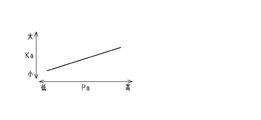
- the asynchronous injection amount calculating process includes a process of calculating the asynchronous injection amount to a large value as compared to the case where the atmospheric pressure is high and the atmospheric pressure is low.
- the atmospheric pressure When the atmospheric pressure is high, the pressure in the intake passage at the start is higher than when the atmospheric pressure is low, so the amount of air charged into the combustion chamber is large. Therefore, in the above configuration, when the atmospheric pressure is high, the asynchronous injection amount is set to a large value as compared with the case where the atmospheric pressure is low. Therefore, the air-fuel ratio of the mixture to be burned in the combustion chamber is prevented from being excessively lean even when the atmospheric pressure is high.
- Example 11 In the control device of Example 10, the internal combustion engine includes a throttle valve.
- the asynchronous injection amount calculating process calculates the asynchronous injection amount to a smaller value when the internal combustion engine is restarted at the start of the internal combustion engine than when the intake pressure is low. including.
- the pressure in the intake passage tends to be lower than the atmospheric pressure, and the pressure in the intake passage tends to converge to the atmospheric pressure as time passes. Therefore, at the time of restart, the pressure in the intake passage may still be lower than the atmospheric pressure. In that case, the fuel vapor is likely to be atomized because the vapor pressure of the fuel in the intake passage is lower than, for example, the atmospheric pressure. Therefore, when the pressure in the intake passage is still lower than the atmospheric pressure at the time of restart, for example, compared with the case where the pressure in the intake passage converges to the atmospheric pressure immediately before the restart, injection from the port injection valve Among the fuels, the amount of fuel remaining in the intake system without flowing into the combustion chamber tends to be small.
- the asynchronous injection amount is calculated to a smaller value than when the intake pressure is high. Therefore, it can be suppressed that the air-fuel ratio of the mixture to be burned in the combustion chamber becomes excessively rich at the time of restart.
- Example 12 The control device according to any one of Examples 9 to 11 is further configured to execute synchronous injection amount calculation processing for calculating a synchronous injection amount which is an injection amount of the intake synchronous injection,
- the synchronous injection amount calculation process calculates the synchronous injection amount based on the temperature of the cooling water of the internal combustion engine without depending on the elapsed time from the stop time of the internal combustion engine to the start.
- the elapsed time from stop to start of the internal combustion engine has a negative correlation with the temperature of the intake system. Therefore, this elapsed time has a positive correlation with the amount of intake asynchronous injection amount, which is the amount of fuel adhering and staying in the intake system without flowing into the combustion chamber.
- the correlation between the elapsed time and the amount of fuel adhering and staying in the intake system without flowing into the combustion chamber among the synchronous injection amounts is the correlation between the elapsed time and the intake asynchronous injection amount in the combustion chamber. It is not as strong as the correlation with the amount of fuel that remains attached to the intake system without flowing into it.
- the asynchronous injection amount is determined according to the elapsed time, while the synchronous injection amount is determined regardless of the elapsed time. Therefore, it is possible to control the injection amount of the non-intake-asynchronous injection, in which the amount of fuel adhering and staying in the intake system without flowing into the combustion chamber becomes remarkable, according to the amount of fuel remaining in the intake system.
- Example 13 It is a control device of an internal combustion engine, and the control device is applied to an internal combustion engine including a port injection valve that injects fuel into an intake passage, and the control device is It is a selection process for selecting one of multi injection processing and single injection processing so as to inject fuel of a required injection amount calculated regardless of the detected value of the intake air amount at the start of the internal combustion engine.
- the multi-injection process includes: an intake synchronous injection that injects fuel in synchronization with an opening period of an intake valve; and an intake asynchronous injection that injects fuel at a timing more advanced than the intake synchronous injection.
- the single injection process includes injecting the fuel of the required injection amount by the intake asynchronous injection;
- the port injection valve is operated to perform an operation process for executing the process selected by the selection process,
- the selection process selects the single injection process when the temperature of the cooling water of the internal combustion engine is equal to or higher than a predetermined water temperature, and the multi-injection process when the temperature of the cooling water is less than the predetermined water temperature.
- Example 14 The present invention is embodied as a control method of an internal combustion engine that executes various processes described in each of the above-described first to thirteenth examples.
- a control method of an internal combustion engine wherein the control method is applied to an internal combustion engine including a port injection valve that injects a fuel into an intake passage, and the control method is: It is a selection process for selecting one of a multi-injection process and a single-injection process to inject fuel of a required injection quantity which is a required injection quantity in one combustion cycle, wherein the multi-injection process is an intake valve An intake synchronous injection that injects the fuel in synchronization with the valve opening period, and an intake asynchronous injection that injects the fuel at a timing on the advanced side of the intake synchronous injection, and the single injection process
- the selection process in which an injection amount of fuel is injected by the intake asynchronous injection; Operation processing for executing the processing selected by the selection processing by operating the port injection valve; The selection process selects the single injection process when the temperature of the intake system of
- Example 15 The present invention is embodied as a non-temporary computer-readable recording medium storing a program that causes a processing apparatus to execute the various processes described in each of the above-described Examples 1 to 13.
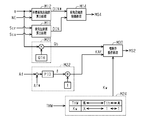
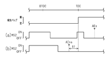
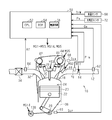
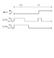
- the figure which shows the control apparatus and internal combustion engine concerning 1st Embodiment which embodied this indication The block diagram which shows the process which a control apparatus performs in the internal combustion engine of FIG. Portions (a) and (b) of FIG. 3 show injection patterns in the internal combustion engine of FIG.
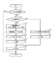
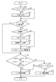
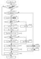
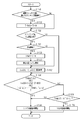
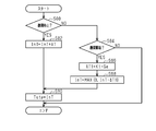
- the flowchart which shows the procedure of injection valve operation processing in the internal combustion engine of FIG. The flowchart which shows the procedure of injection valve operation processing in the internal combustion engine of FIG.
- FIG. 8 show injection patterns in the internal combustion engine of FIG.
- the flowchart which shows the procedure of the process which a control apparatus performs in the internal combustion engine of FIG.
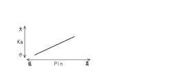
- FIG. 8 is a view showing a relationship between an intake pressure and a pressure correction coefficient in the internal combustion engine of FIG. 7;
- the flowchart which shows the procedure of the process which a control apparatus performs in the internal combustion engine of FIG.
- the flowchart which shows the procedure of the process which the control apparatus concerning 3rd Embodiment which embodied this indication performs.
- FIG. 1 The internal combustion engine 10 shown in FIG. 1 is the only prime mover that generates the thrust of the vehicle.
- a throttle valve 14 and a port injection valve 16 are provided in the intake passage 12 of the internal combustion engine 10 sequentially from the upstream side.
- the air taken into the intake passage 12 and the fuel injected from the port injection valve 16 flow into the combustion chamber 24 divided by the cylinder 20 and the piston 22 as the intake valve 18 is opened.
- the mixture of fuel and air is subjected to combustion by the spark discharge of the igniter 26.
- combustion energy generated by the combustion is converted to rotational energy of the crankshaft 28 via the piston 22.
- the air-fuel mixture supplied to the combustion is discharged to the exhaust passage 32 as the exhaust as the exhaust valve 30 is opened.
- a catalyst 34 is provided in the exhaust passage 32.
- the rotational power of the crankshaft 28 is transmitted to the intake camshaft 40 and the exhaust camshaft 42 via the timing chain 38.
- the power of the timing chain 38 is transmitted to the intake camshaft 40 via the intake valve timing adjustment device 44.
- the intake valve timing adjustment device 44 is an actuator that adjusts the opening timing of the intake valve 18 by adjusting the rotational phase difference between the crankshaft 28 and the intake camshaft 40.
- the control device 50 controls the internal combustion engine 10 and controls the control amount (torque, exhaust component ratio, etc.) of the internal combustion engine 10 by the throttle valve 14, the port injection valve 16, the ignition device 26, and the intake valve.
- the operation unit of the internal combustion engine 10 such as the timing adjustment device 44 is operated.
- the control device 50 outputs an output signal Scr of the crank angle sensor 60, an intake air amount Ga detected by the air flow meter 62, an air-fuel ratio Af detected by the air-fuel ratio sensor 64, an output signal of the intake cam angle sensor 66 Sca, reference is made to the temperature (water temperature THW) of the cooling water of the internal combustion engine 10 detected by the water temperature sensor 68.
- operation signals MS1 to MS5 for operating the throttle valve 14, the port injection valve 16, the ignition device 26, the starter motor 36, and the intake valve timing adjustment device 44 are shown.
- the control device 50 includes a CPU 52, a ROM 54, and a power supply circuit 56.
- the CPU 52 executes a program stored in the ROM 54 to execute control of the control amount.
- the power supply circuit 56 supplies power to each point in the control device 50.
- FIG. 2 shows a part of the process executed by the control device 50.
- the process shown in FIG. 2 is realized by the CPU 52 executing a program stored in the ROM 54.
- the intake phase difference calculation process M10 is a phase difference of the rotation angle of the intake camshaft 40 with respect to the rotation angle of the crankshaft 28 based on the output signal Scr of the crank angle sensor 60 and the output signal Sca of the intake cam angle sensor 66.
- And is a process of calculating the inspiratory phase difference DIN.
- the target intake phase difference calculation processing M12 is processing for variably setting the target intake phase difference DIN * based on the operating point of the internal combustion engine 10. In the present embodiment, the operating point is defined by the rotational speed NE and the filling efficiency ⁇ .
- the CPU 52 calculates the rotational speed NE based on the output signal Scr of the crank angle sensor 60, and calculates the charging efficiency ⁇ ⁇ ⁇ based on the rotational speed NE and the intake air amount Ga.
- the charging efficiency ⁇ is a parameter that determines the amount of fresh air charged into the combustion chamber 24.
- the intake phase difference control process M14 is a process of outputting the operation signal MS4 to the intake valve timing adjustment device 44 in order to operate the intake valve timing adjustment device 44 in order to control the intake phase difference DIN to the target intake phase difference DIN *. is there.
- the base injection amount calculation process M20 is a process of calculating the base injection amount Qb based on the charging efficiency ⁇ .
- the base injection amount Qb is a base value of the fuel amount for making the air-fuel ratio of the air-fuel mixture in the combustion chamber 24 the target air-fuel ratio.
- the base injection amount calculation processing M20 sets the charging efficiency ⁇ to the fuel amount QTH per 1% of the charging efficiency ⁇ for setting the air fuel ratio to the target air fuel ratio.
- the processing may be performed to calculate the base injection amount Qb by multiplication. That is, the base injection amount Qb is a fuel amount calculated to control the air-fuel ratio to the target air-fuel ratio based on the amount of fresh air charged into the combustion chamber 24.
- the target air-fuel ratio may be, for example, the theoretical air-fuel ratio.
- the feedback process M22 is a process of calculating and outputting a feedback correction coefficient KAF obtained by adding “1” to the correction ratio ⁇ of the base injection amount Qb.
- the correction ratio ⁇ of the base injection amount Qb is a feedback operation amount as an operation amount for performing feedback control of the air-fuel ratio Af to the target value Af *. More specifically, the feedback processing M22 is performed according to the difference between each output value of the proportional element and the differential element to which the difference between the air fuel ratio Af and the target value Af * is input and the difference between the air fuel ratio Af and the target value Af *. The sum with the output value of the integral element that holds and outputs the integrated value is taken as a correction ratio ⁇ .
- the low temperature correction process M24 is a process of calculating the low temperature increase coefficient Kw to a value larger than “1” in order to increase the base injection amount Qb when the water temperature THW is less than a predetermined temperature Tth (for example, 60 ° C.). Specifically, the low temperature increase coefficient Kw is calculated to be a larger value than when the water temperature THW is low than when it is high. When the water temperature THW is equal to or higher than the predetermined temperature Tth, the low temperature increase coefficient Kw is “1”, and the correction amount of the base injection amount Qb based on the low temperature increase coefficient Kw is zero.
- a predetermined temperature Tth for example, 60 ° C.
- the injection valve operation process M30 is a process of outputting an operation signal MS2 to the port injection valve 16 so as to operate the port injection valve 16 based on the base injection amount Qb, the feedback correction coefficient KAF, and the low temperature increase coefficient Kw.
- the injection valve operation process M30 is a process of injecting from the port injection valve 16 a required injection amount Qd, which is a fuel amount required to be supplied from the port injection valve 16 to one cylinder in one combustion cycle. is there.
- the required injection amount Qd is “KAF ⁇ Kw ⁇ Qb”.
- the fuel injection process has two processes, that is, the process illustrated in part (a) of FIG. 3 and the process illustrated in part (b) of FIG. 3.
- Part (a) of FIG. 3 includes "intake synchronous injection” which injects fuel in synchronization with the valve opening period of the intake valve 18, and "intake asynchronous” which injects fuel at a timing more advanced than the intake synchronous injection. This is a multi-injection process that executes two fuel injections of “injection”.
- “intake synchronous injection” injects fuel so that the period when the fuel injected from the port injection valve 16 reaches the position before the opening of the intake valve 18 falls within the opening period of the intake valve 18
- “the position before the intake valve 18 is opened” is the downstream end of the intake port, in other words, the inlet portion of the intake port to the combustion chamber 24.
- the start point of the “attainment period” is the timing at which the fuel injected at the earliest timing of the fuel injected from the port injection valve 16 reaches the position before the valve opening of the intake valve 18,
- the end point of the “attainment period” is the timing at which the latest one of the fuel injected from the port injection valve 16 reaches the position before the intake valve 18 is opened.
- “intake asynchronous injection” is to inject fuel so that the fuel injected from the port injection valve 16 reaches the intake valve 18 before the intake valve 18 opens.
- the fuel injected from the port injection valve 16 stays in the intake passage 12 until the intake valve 18 is opened, and the combustion chamber 24 is opened after the intake valve 18 is opened. It is an injection that comes to flow into the inside.
- “intake asynchronous injection” is performed so that the period in which the fuel injected from the port injection valve 16 reaches the position before the opening of the intake valve 18 falls within the closing period of the intake valve 18. Fuel shall be injected.
- Part (b) of FIG. 3 is a single injection process in which only intake asynchronous injection is performed.
- the multi-injection process is performed aiming to reduce the number (PN) of particulate matter (PM) in the exhaust gas. That is, when the temperature of the intake system of the internal combustion engine 10 such as the intake passage 12 and the intake valve 18 is low to a certain extent, the PN tends to increase when the single injection process is performed in the region where the filling efficiency ⁇ is large to a certain extent.
- the reason for this is considered to be that the required injection amount Qd becomes a larger value when the filling efficiency ⁇ is larger than when it is small, and as a result, the amount of fuel adhering to the intake system increases.
- the amount of fuel adhering to the intake system increases to some extent, it is presumed that part of the adhering fuel flows into the combustion chamber 24 as droplets as it is due to the shear of the adhering fuel. Therefore, in the present embodiment, by injecting a part of the required injection amount Qd by the intake synchronous injection, even if the required injection amount Qd is large, the amount of fuel adhering to the intake system can be divided by the required injection amount Qd. To reduce the PN.
- FIG. 4 shows the procedure of the injection valve operation processing M30.
- the process shown in FIG. 4 is realized by the CPU 52 repeatedly executing the program stored in the ROM 54 at a predetermined cycle, for example.
- the step number of each process is expressed by the number to which "S" was provided at the head.
- the CPU 52 first determines whether or not it is within a predetermined period after the starter motor 36 is activated (S10).
- the “predetermined period” is a period in which the amount of air charged into the combustion chamber 24 can not be accurately grasped and the base injection amount Qb can not be accurately computed.
- the CPU 52 determines whether there is a request for multi-injection processing (S12), when it is determined that it is within a predetermined period after the starter motor 36 is started (S10: YES).
- the CPU 52 determines that there is a request for multi-injection processing (S12: YES), it is the injection amount of intake asynchronous injection based on the water temperature THW, the number of injections after starter ON, and the stop time Tstp of the internal combustion engine 10.
- the asynchronous injection amount Qns is calculated (S14).
- the stop time Tstp of the internal combustion engine 10 is an elapsed time from the previous stop of the internal combustion engine 10 to the current start.
- the CPU 52 calculates the asynchronous injection amount Qns to a larger value than when the water temperature THW is low than when it is high. Further, the CPU 52 calculates the asynchronous injection amount Qns to a larger value than when the stop time Tstp is long than when it is short.
- the CPU 52 calculates a synchronous injection amount Qs, which is an injection amount of intake synchronous injection, based on the water temperature THW (S16).
- the CPU 52 calculates the synchronous injection amount Qs to a larger value than when the water temperature THW is low than when it is high.
- the sum of the asynchronous injection amount Qns and the synchronous injection amount Qs is a required injection amount Qd, which is the injection amount required for one combustion cycle. That is, the processing of S14 and S16 can be regarded as processing of dividing the fuel of the required injection amount Qd into the asynchronous injection amount Qns and the synchronous injection amount Qs.
- the CPU 52 calculates an injection start timing Is of intake synchronous injection based on the water temperature THW, the rotational speed NE, and the intake phase difference DIN (S18).
- the map calculation with the water temperature THW, the rotational speed NE, and the intake phase difference DIN as input variables and the injection start timing Is as an output variable is stored in advance in the ROM 54, and the CPU 52 calculates the injection start timing Is Processing.
- “map data” is set data of discrete values of input variables and values of output variables corresponding to the values of the input variables.
- map operation for example, when the value of the input variable matches any of the values of the input variable of map data, the value of the output variable of the corresponding map data is taken as the operation result, while the value of the input variable is If it does not match any of the values of the input variables of the map data, it may be a process in which values obtained by interpolation of the values of a plurality of output variables included in the map data are used as the operation result.
- the CPU 52 calculates the injection start timing Ins of the intake non-synchronous injection (S20).
- the CPU 52 calculates the injection start timing Ins of the intake non-synchronous injection such that the time interval between the injection end timing of the intake non-synchronous injection and the injection start timing Is of the intake synchronous injection becomes a predetermined time or more.
- the "predetermined time” is determined by the structure of the port injection valve 16, and of the two fuel injections adjacent in time series, the injection on the retard side starts before the injection on the advance side ends. It is time to avoid things.
- the CPU 52 operates the port injection valve 16 by outputting the operation signal MS2 to the port injection valve 16 so as to inject the fuel of the asynchronous injection amount Qns at the injection start time Ins, and then the synchronous injection at the injection start time Is.
- the port injection valve 16 is operated by outputting the operation signal MS2 to the port injection valve 16 (S22).
- the CPU 52 determines that there is no request for execution of the multi-injection process (S12: NO)
- the injection amount required for one combustion cycle is based on the water temperature THW, the number of injections after starter ON, and the stop time Tstp A certain required injection amount Qd is calculated (S24).
- the CPU 52 sets the injection start time Isin (S26).
- the CPU 52 operates the port injection valve 16 by outputting the operation signal MS2 to the port injection valve 16 in order to inject the fuel of the required injection amount Qd at the injection start timing Isin (S22).
- FIG. 5 shows the procedure of the injection valve operation process M30.
- the process shown in FIG. 5 is realized by the CPU 52 repeatedly executing the program stored in the ROM 54 at a predetermined cycle, for example.
- the CPU 52 first determines whether a predetermined period has elapsed since the starter motor 36 was turned on (S30). When it is determined that the predetermined period has elapsed since the starter motor 36 was turned on (S30: YES), the CPU 52 determines whether there is a multi-injection request (S32). When it is determined that there is a multi-injection request (S32: YES), the CPU 52 calculates a synchronous injection ratio Ks, which is a ratio of the synchronous injection amount Qs to the base injection amount Qb (S34).
- the CPU 52 calculates the synchronous injection ratio Ks in accordance with the rotational speed NE, the charging efficiency ⁇ , the water temperature THW, and the intake phase difference DIN. Specifically, the synchronous injection ratio is stored by the CPU 52 in a state where map data having the rotational speed NE, the filling efficiency ⁇ , the water temperature THW, and the intake phase difference DIN as input variables and the synchronous injection ratio Ks as an output variable is stored in advance in the ROM 54. Ks is subjected to map calculation.
- the CPU 52 calculates an asynchronous injection ratio Kns as a ratio of the asynchronous injection amount Qns to the required injection amount Qd (S36). Specifically, the CPU 52 calculates the asynchronous injection ratio Kns by subtracting “Ks / (KAF ⁇ Kw)” from “1”. Next, the CPU 52 substitutes a value obtained by multiplying the base injection amount Qb by the synchronous injection ratio Ks for the synchronous injection amount Qs (S38). Next, the CPU 52 substitutes a value obtained by multiplying the required injection amount Qd by the asynchronous injection ratio Kns as the asynchronous injection amount Qns (S40).
- the asynchronous injection amount Qns has the following value.
- Kns KAF Kw Qb KAF Kw Qb-Ks Qb Therefore, the sum of the asynchronous injection amount Qns and the synchronous injection amount Qs is “KAF ⁇ Kw ⁇ Qb”, which is equal to the required injection amount Qd. That is, the fuel of the required injection amount Qd is divided into the asynchronous injection amount Qns and the synchronous injection amount Qs by the processes of S34 to S40.
- the synchronous injection amount Qs is “Ks ⁇ Qb” without being influenced by the values of the feedback correction coefficient KAF and the low temperature increase coefficient Kw.
- the reason for fixing the synchronous injection amount Qs is that the change in the exhaust gas component ratio when changing the synchronous injection amount Qs is more prominent than the change in the exhaust gas component ratio when changing the asynchronous injection amount Qns It is from.
- the fuel injected at the latest timing among the fuel injected from the port injection valve 16 is of the intake valve 18
- the target value of the timing to reach the position in the valve closing period (the downstream end of the intake port, in other words, the inlet portion to the combustion chamber 24) is shown in part (a) of FIG.
- the arrival end time AEs is calculated (S42).
- the CPU 52 calculates the injection start timing Is of the intake synchronous injection based on the arrival end timing AEs, the synchronous injection amount Qs, and the rotational speed NE (S44).
- the CPU 52 calculates the injection start timing Is to a more advanced value than when the synchronous injection amount Qs is large than when it is small. Further, the CPU 52 sets the injection start timing Is to a more advanced side value than when the rotational speed NE is large, as compared with the case where the rotational speed NE is small. Specifically, the CPU 52 adds the injection period by the port injection valve 16 determined from the synchronous injection amount Qs, and the flight time until the fuel injected from the port injection valve 16 reaches the position at which the intake valve 18 is closed.
- the injection start timing Is is a timing advanced by the value with respect to the arrival end timing AEs.
- the CPU 52 calculates the injection start time Ins of the asynchronous injection based on the injection start time Is (S46).
- the time interval between the injection end timing of the intake non-synchronous injection and the injection start timing Is is set to be equal to or longer than the above-described predetermined time.
- the injection start timing Is of the intake synchronous injection is set independently of the injection start timing Ins of the intake asynchronous injection.
- the reason is that the arrival completion timing AEs of the intake synchronous injection is particularly susceptible to PN and HC in the exhaust gas.
- the CPU 52 outputs the operation signal MS2 to the port injection valve 16 so as to inject the fuel of the asynchronous injection amount Qns at the injection start timing Ins, and then inject the fuel of the synchronous injection amount Qs at the injection start timing Is. Then, the port injection valve 16 is operated (S48).
- the CPU 52 substitutes “KAF ⁇ Kw ⁇ Qb” for the required injection amount Qd (S51).
- the CPU 52 calculates the injection start timing Isin of single injection (S53). Specifically, as shown in the part (b) of FIG. 3, the CPU 52 opens the valve opening timing of the intake valve 18 (a broken line extending across the parts (a) and (b) in FIG. 3). A timing advanced by a predetermined amount ⁇ 1 is taken as an arrival end time AEns.
- the CPU 52 adds the injection period by the port injection valve 16 determined from the required injection amount and the flight time until the fuel injected from the port injection valve 16 reaches the position at which the intake valve 18 is closed.
- the timing advanced with respect to the arrival end timing AEs is taken as the injection start timing Isin of the single injection.
- the CPU 52 operates the port injection valve 16 by outputting the operation signal MS2 to the port injection valve 16 in order to inject the fuel of the required injection amount Qd at the injection start timing Isin (S48).
- FIG. 6 shows the procedure of the process related to the determination of the execution request of the multi-injection process, among the injection valve operation process M30.
- the process shown in FIG. 6 is realized by the CPU 52 repeatedly executing the program stored in the ROM 54 at a predetermined cycle, for example.
- the CPU 52 determines whether or not it is time to restart the internal combustion engine 10 (S56).
- “at restart” means that the internal combustion engine 10 is stopped after the internal combustion engine 10 is stopped by the automatic stop processing (idling stop control) of the internal combustion engine 10 when the IG signal is in the on state. It means that it is when the automatic start process is done.
- the CPU 52 substitutes the water temperature THW at the present time into the restart-time water temperature THW1 (S58).
- the CPU 52 acquires a stop time Tstp as an elapsed time from the time of automatic stop of the internal combustion engine 10 to the present time (S60).
- the CPU 52 updates the total integrated air amount InG0, which is an integrated value of the intake air amount after the starter motor 36 is activated ( S62).
- the total integrated air amount InG0 may be updated by a value obtained by adding the intake air amount Ga to the value of the total integrated air amount InG0 in the previous processing of S62.
- the initial value of the total integrated air amount InG0 is "0".
- the CPU 52 updates the integrated air amount InG1 after restart, which is the integrated value of the intake air amount Ga from the time of restart. Note that the initial value of the integrated air amount InG1 after restart is “0”, and the integrated air amount InG1 after restart is initialized each time it is restarted.
- the CPU 52 proceeds to the process of S64.
- the CPU 52 performs the condition (i) that the total integrated air amount InG0 is the determination value Inth0 or more, the condition (ii) that the integrated air amount InG1 after restart is the determination value Inth1 or more, It is determined whether the logical product with the condition (iii) that the water temperature THW at the present time is equal to or higher than the predetermined temperature Tth is true.
- This process is a process of determining whether the temperature of the intake system of the internal combustion engine 10 including the intake passage 12 and the intake valve 18 is equal to or higher than a specified temperature.
- “prescribed temperature” is set to a value at which PN falls within an allowable range even when single injection processing is performed.
- predetermined temperature Tth it is desirable to set more than prescription
- the CPU 52 calculates the determination value Inth0 to be a larger value when the initial water temperature THW0 is low than when it is high. This may be realized, for example, by performing the map operation of the determination value Inth0 by the CPU 52 in a state in which the initial water temperature THW0 is an input variable and map data having the determination value Inth0 as an output variable is stored in the ROM 54 in advance. Further, the CPU 52 calculates the determination value Inth1 to be a larger value when the restart-time water temperature THW1 is high than when it is low. Further, the CPU 52 calculates the determination value Inth1 to a larger value when the stop time Tstp is longer than when it is short.
- the CPU 52 sets the determination value Inth1 to zero. Therefore, the condition (ii) is automatically established when the restart is not performed.
- the CPU 52 selects single injection processing (S66).
- the CPU 52 determines that the logical product of the conditions (i) to (iii) is false (S64: NO)
- the water temperature THW is equal to or higher than the low threshold TL lower than the predetermined temperature Tth. It is determined (S68).
- “low threshold value TL” is the time between the injection end timing of the intake asynchronous injection and the injection start timing Is of the intake synchronous injection because the required injection amount Qd becomes excessively large due to the low water temperature THW.
- the CPU 52 stores the water temperature THW at that time as “initial water temperature THW0”. Further, when the execution request of the automatic start process after the automatic stop process is generated, the CPU 52 stores the water temperature THW at that time as “the restart time water temperature THW1”. After activating the starter motor 36, the CPU 52 starts fuel injection.
- the required injection amount Qd is determined according to the water temperature THW.
- the determination value Inth0 is set to be zero when the initial water temperature THW0 is equal to or higher than the high threshold value higher than the predetermined temperature Tth.
- the determination value Inth1 is set to be zero when the restart-time water temperature THW1 is equal to or higher than the high threshold value. Therefore, when the water temperature THW at the start of the starter motor 36 is equal to or higher than the high threshold, the CPU 52 executes the single injection process, and executes the multi-injection process if the water temperature THW is lower than the high threshold.
- the CPU 52 determines that the total integrated air amount InG0 and the integrated air amount InG1 after restart are each determined in addition to the water temperature THW being equal to or higher than the predetermined temperature Tth. If Inth0 and Inth1 or more, it is not necessary to execute the multi-injection process from the viewpoint of PN reduction, and the single injection process is performed. Here, even if the water temperature THW is equal to or higher than the predetermined temperature Tth, the total integrated air amount InG0 may be less than the determination value Inth0, or the integrated air amount InG1 after restart may be less than the determination value Inth1.
- the temperature of the intake valve 18 may be less than the specified temperature.
- the reason for this is that the intake valve 18 directly receives the heat in the combustion chamber 24 and the temperature of the intake valve 18 largely depends on the amount of heat generated in the combustion chamber 24. Therefore, the temperature of the intake valve 18 depends on the water temperature THW. It is because it is not decided uniquely. Therefore, when the total integrated air amount InG0 is less than the determination value Inth0, or when the integrated air amount InG1 after restart is less than the determination value Inth1, the temperature of the intake valve 18 is still high although the water temperature THW is high. It can happen that it is not high enough.
- the predetermined temperature Tth which is the judgment value of the water temperature THW
- the predetermined temperature Tth must be set to an excessively large value. That is, even when the process proceeds to the single injection process and the PN can be made within the allowable range, the multi-injection process may be performed.
- the conditions (i) and the conditions (ii) are provided. Therefore, for example, in the present embodiment, the predetermined temperature Tth can be set to a smaller value as compared with the case where it is determined whether or not there is a request for execution of the multi-injection process only from the above condition (iii). Therefore, when PN can be made into the tolerance
- the “multi-injection process” corresponds to the process shown in part (a) of FIG. 3, and the “single-injection process” corresponds to the process shown in part (b) of FIG. 3.
- the “selection process” corresponds to the process of FIG. 6, and the “operation process” corresponds to the processes of S22 and S48.
- the “determination process” corresponds to the process of S64
- the “required injection amount calculation process” corresponds to the base injection amount calculation process M20, the feedback process M22, and the low temperature correction process M24. That is, since the required injection amount Qd is "Qb KAF Kw", the required injection amount Qd can be calculated by calculating the base injection amount Qb, the feedback correction coefficient KAF, and the low temperature increase coefficient Kw by each of the above processes. Can be considered as calculated.
- the “first determination value changing process” corresponds to the determination value Inth0 and the determination value Inth1 being set in accordance with the water temperature in the process of S64.
- the “second determination value changing process” corresponds to the case where the determination value Inth1 is set according to the stop time Tstp in the process of S64.
- the "determination process” corresponds to the process of S64. ⁇ Other Embodiments>
- the present embodiment can be modified as follows. The present embodiment and the following modifications can be implemented in combination with one another as long as there is no technical contradiction.
- the required injection amount Qd is calculated based on the water temperature THW, the number of injections, and the stop time Tstp, but the invention is not limited thereto.
- the required injection amount Qd is calculated based on only the water temperature THW among the above three parameters, calculated based only on the water temperature THW and the number of injections, or calculated based on only the water temperature THW and the stop time Tstp It is also good.
- the base injection amount Qb may be corrected by the learning value LAF by adding the required injection amount Qd to the low temperature increase coefficient Kw or the feedback correction coefficient KAF.
- the "calculation process of the learning value LAF” is a process of receiving the feedback correction coefficient KAF and updating the learning value LAF so that the correction ratio of the base injection amount Qb by the feedback correction coefficient KAF becomes small.
- the learning value LAF is desirably stored in an electrically rewritable non-volatile memory.
- the required injection amount Qd may be calculated by feedforward control based on the ratio of the disturbance fuel, for example, so that the required injection amount Qd is smaller than when the ratio of the disturbance fuel is large.
- the “ratio of disturbed fuel” is the ratio of fuel (disturbed fuel) other than the fuel injected from the port injection valve 16 in one combustion cycle to the amount of fuel flowing into the combustion chamber 24 in one combustion cycle.
- the “disturbance fuel” for example, a canister for collecting fuel vapor from a fuel tank storing the fuel injected from the port injection valve 16 and an inflow of the fluid in the canister into the intake passage 12
- the internal combustion engine is provided with an adjusting device to adjust, there is fuel vapor flowing into the intake passage 12 from the canister.
- there is fuel vapor flowing into the intake passage 12 from the crankcase for example, in the case where a system for returning fuel vapor in the crankcase to the intake passage 12 is provided, there is fuel vapor flowing into the intake passage 12 from the crankcase.
- the fuel is injected such that the fuel injected from the port injection valve 16 reaches the closing period of the intake valve 18 during the period when the fuel reaches the position before the opening of the intake valve 18.
- asynchronous injection was dealt with, it is not limited to this.
- the rotational speed NE is high and the asynchronous injection amount Qns is excessively large, a part of the period during which the fuel injected from the port injection valve 16 reaches the position before opening the intake valve 18 is the intake valve 18. It may overlap with the opening period of
- the injection start timing Is is set based on the water temperature THW, the rotational speed NE, and the intake phase difference DIN, but the invention is not limited thereto.
- the injection start timing Is may be set based on only one of the above three parameters, or may be set based on only two.
- the arrival end timing AEs is set based on the rotational speed NE, the filling efficiency ⁇ , the water temperature THW, and the intake phase difference DIN.
- the injection start timing Is may be set directly based on the rotational speed NE, the filling efficiency ⁇ , the water temperature THW, and the intake phase difference DIN.
- a base injection amount Qb may be used instead of the charging efficiency ⁇ .
- arrival end timing AEs and injection start timing Is are variably set based on only three parameters, or based on only two parameters. It may be variably set or variably set based on only one parameter.
- the fuel injection from the port injection valve 16 is performed as a single process of injecting the fuel so that the period when the fuel reaches the position before the valve opening of the intake valve 18 falls within the valve closing period of the intake valve 18.
- the injection processing was dealt with, it is not restricted to this. For example, when the required injection amount Qd is large, a part of the period in which the fuel injected from the port injection valve 16 reaches the position before the valve opening of the intake valve 18 overlaps with the valve closing period of the intake valve 18 May be.
- the integrated air amount InG1 after restart under the condition (ii) is an integrated value of the intake air amount Ga from the immediately preceding start regardless of whether it is restart or not
- the judgment value Inth1 is set to be variably set based on the water temperature THW at the time of the immediately preceding start and the elapsed time from the immediately preceding stop to the immediately preceding start. Further, for example, when the condition (iv) is satisfied, it may be determined that the temperature of the intake system is equal to or higher than the specified temperature.
- the idling stop control is performed, but the invention is not limited thereto.
- it may be a so-called hybrid vehicle provided with a rotating electrical machine in addition to the internal combustion engine as a prime mover for generating the thrust of the vehicle.
- the logical product of the conditions (iv) and (iii) is true, it may be determined that the temperature of the intake system is equal to or higher than the specified temperature.
- condition (i), the condition (ii), and the condition (iii) it may be determined that the temperature of the intake system is equal to or higher than the specified temperature.
- condition (i) is to set the integrated value of the intake air amount Ga after the signal for enabling the vehicle to travel is switched from off to on as the total integrated air amount InG0.
- condition (ii) is a condition that the integrated value of the intake air amount Ga from the second start onward after the signal that enables traveling is switched from off to on is the integrated air amount InG1 after restart is there.
- the temperature of the intake system is equal to or higher than the specified temperature when the logical product of the above conditions (i) and conditions (iii) is true.
- the condition (i) when the condition (i) is satisfied, it may be determined that the temperature of the intake system is equal to or higher than the specified temperature, and for example, when the condition (iii) is satisfied, the temperature of the intake system is specified. It may be determined that the temperature is equal to or higher.
- the determination value Inth0 or the determination value Inth1 may be variably set according to the alcohol concentration.
- the determination value Inth0 and the determination value Inth1 are set to larger values than when the alcohol concentration is high and low.
- Condition (v) The condition that the filling efficiency ⁇ is a predetermined value or more. This condition is a condition that if single injection processing is performed, the amount of fuel adhering to the intake passage 12 becomes excessively large, which may result in remarkable PN. However, this condition is a condition after a predetermined period has elapsed after the starter is turned on.
- This condition is a condition that the time interval between the end timing of the intake asynchronous injection and the injection start timing Is of the intake synchronous injection can be ensured to be longer than the predetermined time. Further, this condition is a condition to suppress that the calorific value becomes excessive due to the increase of the calculation load of the control device 50, since the multi-injection process has a larger calculation load than the single injection process.
- the ratio of the synchronous injection amount Qs to the base injection amount Qb is determined based on the rotational speed NE, the filling efficiency ⁇ , the water temperature THW, and the intake phase difference DIN.
- the synchronous injection ratio Ks shown is variably set, it is not limited to this.
- the required injection amount Qd may be used instead of the filling efficiency ⁇ as a load parameter which is a parameter indicating the amount of fresh air charged into the combustion chamber 24.
- load parameter is a parameter indicating the amount of fresh air charged into the combustion chamber 24.
- synchronous injection ratio Ks is variably set based on only three parameters, or variably set based on only two parameters.
- Or may be variably set based on only one parameter. At this time, it is desirable to variably set the synchronous injection ratio Ks by using at least one of the load parameter and the water temperature THW as much as possible. Further, in addition to the above four parameters, for example, an intake pressure or a flow velocity of intake air may be used. However, according to the above four parameters, the intake pressure and the flow velocity of the intake air can be grasped.
- the synchronous injection amount Qs may be calculated based on the parameter for which the synchronous injection ratio Ks is determined in the above embodiment and the modification thereof.
- the asynchronous injection amount Qns may be set as "Qb KAF Kw-Qs".
- the synchronous injection amount Qs for example, a value obtained by dividing the value “KAF ⁇ Qb” obtained by correcting the base injection amount Qb with the feedback correction coefficient KAF using the synchronous injection ratio Ks may be used as the synchronous injection amount Qs.
- the synchronous injection amount Qs is “Ks ⁇ KAF ⁇ Qb”.
- variable characteristic device for changing the characteristic of the intake valve 18 is not limited to the intake valve timing adjustment device 44.
- the lift amount of the intake valve 18 may be changed.
- the lift amount etc. may be used instead of the intake phase difference DIN in the above embodiment or its modification. Good.
- control device is not limited to one that includes the CPU 52 and the ROM 54 and executes software processing.
- a dedicated hardware circuit for example, an ASIC or the like
- the control device may have any one of the following configurations (a) to (c).
- B A processing device and a program storage device that execute part of the above processing according to a program, and a dedicated hardware circuit that performs the remaining processing.
- a dedicated hardware circuit is provided to execute all of the above processes.
- the software processing circuit provided with the processing device and the program storage device, and a dedicated hardware circuit may be plural. That is, the above process may be performed by a processing circuit including at least one of one or more software processing circuits and one or more dedicated hardware circuits.
- a throttle valve 14 and a port injection valve 16 are provided in the intake passage 12 of the internal combustion engine 10 shown in FIG. 7 sequentially from the upstream side.
- the air taken into the intake passage 12 and the fuel injected from the port injection valve 16 flow into the combustion chamber 24 divided by the cylinder 20 and the piston 22 as the intake valve 18 is opened.
- the mixture of fuel and air is subjected to combustion by the spark discharge of the igniter 26.
- combustion energy generated by the combustion is converted to rotational energy of the crankshaft 28 via the piston 22.
- the air-fuel mixture supplied to the combustion is discharged to the exhaust passage 32 as the exhaust as the exhaust valve 30 is opened.
- a catalyst 34 is provided in the exhaust passage 32.
- the rotational power of the crankshaft 28 is transmitted to the intake camshaft 40 and the exhaust camshaft 42 via the timing chain 38.
- the power of the timing chain 38 is transmitted to the intake camshaft 40 via the intake valve timing adjustment device 44.
- the intake valve timing adjustment device 44 is an actuator that adjusts the opening timing of the intake valve 18 by adjusting the rotational phase difference between the crankshaft 28 and the intake camshaft 40.
- the crankshaft 28 is mechanically connected to a motor generator 136 that generates the thrust of the vehicle together with the internal combustion engine 10. That is, the vehicle according to the present embodiment is a hybrid vehicle in which the internal combustion engine 10 and the motor generator 136 are used as a thrust generating device of the vehicle.
- the control device 50 controls the internal combustion engine 10 and controls the control amount (torque, exhaust component ratio, etc.) of the internal combustion engine 10 by the throttle valve 14, the port injection valve 16, the ignition device 26, and the intake valve.
- the operation unit of the internal combustion engine 10 such as the timing adjustment device 44 is operated.
- the control device 50 controls the throttle valve 14 among the output signal Scr of the crank angle sensor 60, the intake air amount Ga detected by the air flow meter 62, and the pressure in the intake passage 12 detected by the intake pressure sensor 70.
- the controller 50 controls the air-fuel ratio Af detected by the air-fuel ratio sensor 64, the output signal Sca of the intake cam angle sensor 66, the temperature of the cooling water of the internal combustion engine 10 detected by the water temperature sensor 68 (water temperature THW), The atmospheric pressure Pa detected by the atmospheric pressure sensor 72 is referred to.
- control device 50 controls motor generator 136 as a control target, and controls the control amount (torque, rotational speed, etc.) of motor generator 136. 7, operation signals MS1 to MS3, MS14, and MS5 for operating the throttle valve 14, the port injection valve 16, the ignition device 26, the motor generator 136, and the intake valve timing adjustment device 44 are described. doing.
- the control device 50 includes a CPU 52, a ROM 54, and a power supply circuit 56.
- the CPU 52 executes a program stored in the ROM 54 to execute control of the control amount.
- the power supply circuit 56 supplies power to each point in the control device 50.
- the fuel injection process has two processes, that is, the process illustrated in part (a) of FIG. 8 and the process illustrated in part (b) of FIG. 8.
- Part (a) of FIG. 8 includes “intake synchronous injection” which injects fuel synchronously with the valve opening period of the intake valve 18, and “intake asynchronous” which injects fuel at a timing more advanced than the intake synchronous injection. This is a multi-injection process that executes two fuel injections of “injection”.
- the start point of the “attainment period” is the timing at which the fuel injected at the earliest timing among the fuel injected from the port injection valve 16 reaches the position before the valve opening of the intake valve 18,
- the end point of the “arriving period” is the timing at which the fuel injected at the latest timing among the fuel injected from the port injection valve 16 reaches the position before the opening of the intake valve 18.
- “intake asynchronous injection” injects fuel such that the fuel injected from the port injection valve 16 reaches the intake valve 18 before the intake valve 18 opens.
- the fuel injected from the port injection valve 16 stays in the intake passage 12 until the intake valve 18 opens, and after the intake valve 18 opens, the fuel is injected into the combustion chamber 24. It is injection that flows in.
- “intake asynchronous injection” is performed so that the period in which the fuel injected from the port injection valve 16 reaches the position before the opening of the intake valve 18 falls within the closing period of the intake valve 18. Fuel shall be injected.
- Part (b) of FIG. 8 is a single injection process in which only intake asynchronous injection is performed.
- the multi-injection process is performed aiming to reduce the number (PN) of particulate matter (PM) in the exhaust gas. That is, when the temperature of the intake system of the internal combustion engine 10 such as the intake passage 12 and the intake valve 18 is low to a certain extent, the PN tends to increase when the single injection processing is performed. The reason for this is that when the temperature of the intake system is low, the required injection amount, which is the amount of fuel to be injected from the port injection valve 16 in one combustion cycle, becomes a large value, and as a result, the amount of fuel adhering to the intake system is It is considered to be caused by the increase.
- PN particulate matter
- the amount of fuel attached to the intake system increases to a certain extent, it is presumed that part of the attached fuel flows into the combustion chamber 24 as droplets as it is due to the shear of the attached fuel. Therefore, in the present embodiment, even when the required injection amount is large, by injecting a part of the required injection amount by the intake synchronous injection, the amount of fuel adhering to the intake system can be reduced while the required injection amount is large. And, in turn, reduce the PN.
- FIG. 9 shows the procedure of the process at the start of the internal combustion engine 10 according to the present embodiment.
- the process shown in FIG. 9 is realized by the CPU 52 repeatedly executing the program stored in the ROM 54 at a predetermined cycle, for example.
- the step number of each process is expressed by the number to which "S" was provided at the head.
- the CPU 52 first determines whether it is within a predetermined period after the start of cranking (S110).
- predetermined period means that the amount of air charged into the combustion chamber 24 can not be accurately grasped depending on the amount of intake air Ga detected by the air flow meter 62, and as a result, the amount of intake air Ga It is assumed that the required injection amount can not be calculated accurately based on the above.
- the CPU 52 determines whether there is a request for multi-injection processing (S112).
- asynchronous base injection which is a base value of the injection amount for intake asynchronous injection, based on the water temperature THW and the number of injections after cranking starts.
- the quantity Qnsb is calculated (S114).
- the CPU 52 calculates the asynchronous base injection amount Qnsb to a larger value than when the water temperature THW is low than when the water temperature THW is high.
- This processing is realized by the map operation of the asynchronous base injection amount Qnsb by the CPU 52 in a state where map data using the water temperature THW and the injection number as input variables and the asynchronous base injection amount Qnsb as an output variable is stored in advance in the ROM 54.
- map data is set data of discrete values of input variables and values of output variables corresponding to the values of the input variables.
- map operation for example, when the value of the input variable matches any of the values of the input variable of map data, while the value of the output variable of the corresponding map data is taken as the operation result, the map does not match.
- a process may be performed in which a value obtained by interpolation of values of a plurality of output variables included in data is used as a calculation result.
- the CPU 52 determines whether it is time to restart the internal combustion engine 10 (S116).
- “at the time of restart of the internal combustion engine 10” is at the time of the second and subsequent start-up of the internal combustion engine 10 in a period from when the start switch of the vehicle is turned on to when it is turned off.
- the "start switch of the vehicle” is a switch for enabling the vehicle to run by releasing the brake and operating the accelerator.
- the CPU 52 calculates a pressure correction coefficient Ka, which is a correction coefficient of the asynchronous base injection amount Qnsb, according to the atmospheric pressure Pa (S118). Specifically, as shown in FIG.
- the pressure correction coefficient Ka is calculated to be a larger value when the atmospheric pressure Pa is high than when it is low.
- the reason is that when the atmospheric pressure Pa is high, the pressure in the intake passage 12 at the time of start-up is higher than when the atmospheric pressure Pa is low, so that the amount of air charged into the combustion chamber 24 is increased. It is a thing. That is, when the amount of air charged into the combustion chamber 24 is large because the atmospheric pressure Pa is high, the asynchronous injection amount Qns, which is the injection amount of the intake asynchronous injection, is set to a large value as compared with the small amount. Therefore, even when the atmospheric pressure Pa is high, the air-fuel ratio of the mixture to be burned in the combustion chamber 24 is prevented from becoming excessively lean.
- This process can be realized by the map calculation of the pressure correction coefficient Ka by the CPU 52 in a state where map data with the atmospheric pressure Pa as an input variable and the pressure correction coefficient Ka as an output variable is stored in the ROM 54 in advance.
- the CPU 52 when determining that the internal combustion engine 10 is restarted (S116: YES), the CPU 52 variably sets the pressure correction coefficient Ka in accordance with the atmospheric pressure Pa and the intake pressure Pin (S120).
- the CPU 52 calculates the pressure correction coefficient Ka to a larger value than when the atmospheric pressure Pa is high as compared to when the atmospheric pressure Pa is high, as in the case where the restart is not performed.
- the CPU 52 calculates the pressure correction coefficient Ka to a smaller value as compared with the case where the intake pressure Pin is low, and the case where it is high.
- the pressure in the intake passage 12 may still be lower than the atmospheric pressure Pa when the internal combustion engine 10 is restarted, in which case the pressure in the intake passage 12 is the atmospheric pressure Pa.
- the fuel vapor is likely to be atomized because the vapor pressure of the fuel in the intake passage 12 is lower than that in the case of FIG. That is, when fuel is likely to be atomized, for example, the fuel injected from the port injection valve 16 flows into the combustion chamber 24 as compared with the case where the pressure in the intake passage 12 converges to the atmospheric pressure immediately before restart. There is a tendency for the amount of fuel remaining in the intake system of the internal combustion engine 10 to be reduced.
- the CPU 52 maps the pressure correction coefficient Ka in a state where map data with the atmospheric pressure Pa and the intake pressure Pin as input variables and the pressure correction coefficient Ka as an output variable is stored in the ROM 54 in advance.
- the CPU 52 calculates the asynchronous base injection amount Qnsb based on the stop time Tstp of the internal combustion engine 10, which is the elapsed time from the previous stop of the internal combustion engine 10 to the current start.
- the stop time correction coefficient Ks1 for the above is calculated (S122). Specifically, as shown in FIG. 11, the CPU 52 calculates the stop time correction coefficient Ks1 to be a larger value than when the stop time Tstp is long and shorter. That is, this process is a process of calculating the asynchronous injection amount Qns to a smaller value than in the case where the elapsed time (Tstp) from the stop time of the internal combustion engine 10 to the start is short.
- This process can be realized by the CPU 52 performing a map calculation of the stop time correction coefficient Ks1 in a state where map data with the stop time Tstp as an input variable and the stop time correction coefficient Ks1 as an output variable is stored in advance in the ROM 54.
- the CPU 52 substitutes a value obtained by multiplying the pressure correction coefficient Ka and the stop time correction coefficient Ks1 by the asynchronous base injection amount Qnsb for the asynchronous injection amount Qns (S124 ).
- the CPU 52 determines whether it is time to restart (S126).
- the synchronous injection amount Qs which is the injection amount of the intake synchronous injection, is calculated based on the water temperature THW and the atmospheric pressure Pa (S128).
- the CPU 52 calculates the synchronous injection amount Qs based on the water temperature THW, the atmospheric pressure Pa, and the intake pressure Pin (S130). The reason for using the water temperature THW, the atmospheric pressure Pa, and the intake pressure Pin in the processes of S128 and S130 is the same as in the case of the calculation of the asynchronous injection amount Qns.
- the processing of S114 to S130 is performed using the required injection amount as the asynchronous injection amount Qns and the synchronous injection amount Qs. It can be considered as processing to divide.
- the CPU 52 calculates the injection start timing Is of the intake synchronous injection based on the water temperature THW, the rotational speed NE, and the intake phase difference DIN (S132).
- the map calculation with the water temperature THW, the rotational speed NE, and the intake phase difference DIN as input variables and the injection start timing Is as an output variable is stored in advance in the ROM 54, and the CPU 52 calculates the injection start timing Is Processing.
- the intake phase difference DIN is a phase difference of the rotation angle of the intake camshaft 40 with respect to the rotation angle of the crankshaft 28.
- the intake phase difference DIN may be a fixed value at the time of start. Even in such a case, it is effective to calculate the injection start timing Is according to the intake phase difference DIN when the fixed value of the intake phase difference DIN at the time of start differs depending on the vehicle.
- the CPU 52 calculates the injection start timing Ins of the intake non-synchronous injection so that the intake non-synchronous injection ends at least a predetermined time before the injection start timing Is of the intake synchronous injection (S134).
- the "predetermined time” is determined by the structure of the port injection valve 16, and of the two fuel injections adjacent in time series, the injection on the retard side starts before the injection on the advance side ends. It is time to avoid things.
- the CPU 52 causes the port injection valve 16 to inject fuel of the asynchronous injection amount Qns at the injection start timing Ins, and causes the port injection valve 16 to inject fuel of the synchronous injection amount Qs at the injection start timing Is.
- the port injection valve 16 is operated by outputting the operation signal MS2 to 16 (S136).
- the CPU 52 determines that there is no request for execution of the multi-injection process (S112: NO), it is required for one combustion cycle based on the water temperature THW, the number of injections after the start of cranking, and the stop time Tstp A required injection amount Qd, which is an injection amount, is calculated (S138).
- the CPU 52 sets the injection start time Isin (S40). Then, when the injection start timing Isin comes, the CPU 52 operates the port injection valve 16 by outputting the operation signal MS2 to the port injection valve 16 in order to inject the fuel of the required injection amount Qd (S136).
- FIG. 12 shows the procedure of the process related to the determination of the execution request of the multi injection process.
- the process shown in FIG. 12 is realized by the CPU 52 repeatedly executing the program stored in the ROM 54 at a predetermined cycle, for example.
- the CPU 52 first determines whether it is the first cranking start time after the start switch of the vehicle is turned on (S150). When the CPU 52 determines that it is the first cranking start time after the start switch of the vehicle is turned on (S150: YES), the CPU 52 substitutes the current water temperature THW into the initial water temperature THW0 (S152). The CPU 52 can calculate the required injection amount Qd accurately with the intake air amount Ga detected by the air flow meter 62 after cranking when the processing of S152 is completed or when the determination of S150 is negative. It is determined whether it is possible to obtain a value (S154). In this process, it is determined whether or not the above-mentioned predetermined period has not elapsed since the air flow meter 62 can not accurately grasp the amount of air charged into the combustion chamber 24 after the cranking starts.
- the CPU 52 determines that the intake air amount Ga detected by the air flow meter 62 after cranking can be obtained as the value capable of accurately calculating the required injection amount Qd (S154: YES)
- the engine 52 of the internal combustion engine 10 It is determined whether it is a restart time (S156).
- the CPU 52 substitutes the water temperature THW at the present time into the restart-time water temperature THW1 (S158).
- the CPU 52 acquires a stop time Tstp as an elapsed time from the automatic stop immediately before the internal combustion engine 10 to the present time (S160).
- the CPU 52 updates the total integrated air amount InG0, which is an integrated value of the intake air amount after the start of the first cranking, when the process of S160 is completed or when the determination of S156 is negative.
- the total integrated air amount InG0 may be updated by a value obtained by adding the intake air amount Ga to the value of the total integrated air amount InG0 in the previous processing of S162.
- the initial value of the total integrated air amount InG0 is "0".
- the CPU 52 updates the integrated air amount InG1 after restart, which is the integrated value of the intake air amount Ga from the time of restart, in addition to the update of the total integrated air amount InG0. .
- the initial value of the integrated air amount InG1 after restart is “0”, and the integrated air amount InG1 after restart is initialized each time it is restarted.
- the CPU 52 proceeds to the process of S164.
- the CPU 52 re-conditions that the water temperature THW at the present time is the water prescribed temperature Tth1 or more, the condition (xi) that the total integrated air amount InG0 is the judgment value Inth0 or more, and (xii) It is determined whether the logical product with the condition (xiii) indicating that the integrated air amount InG1 after start is greater than or equal to the determination value Inth1 is true.
- the CPU 52 calculates the determination value Inth0 to be a larger value when the initial water temperature THW0 is low than when it is high. This may be realized, for example, by performing the map operation of the determination value Inth0 by the CPU 52 in a state in which the initial water temperature THW0 is an input variable and map data having the determination value Inth0 as an output variable is stored in the ROM 54 in advance. Further, the CPU 52 calculates the determination value Inth1 to be a larger value when the restart-time water temperature THW1 is low than when the water temperature THW1 is high. Further, the CPU 52 calculates the determination value Inth1 to a larger value when the stop time Tstp is longer than when it is short.
- the determination value Inth0 is set to zero.
- the determination value Inth1 is set to zero.
- the stop time Tstp is equal to or less than the specified time
- the determination value Inth1 is set to zero. Note that the CPU 52 sets the determination value Inth1 to zero when it is not after the restart. Therefore, the condition (xiii) is automatically established when the restart is not performed.
- the CPU 52 selects single injection processing (S166).
- the CPU 52 determines that the logical product of the conditions (xi) to (xiii) is false (S164: NO)
- the water temperature THW is equal to or higher than the low threshold TL lower than the water specified temperature Tth1. It is determined whether or not (S168).
- the low threshold value TL is a time interval between the injection end timing of the intake asynchronous injection and the injection start timing Is of the intake synchronous injection because the required injection amount Qd becomes excessively large because the water temperature THW is low.
- the CPU 52 determines whether or not the predetermined time can not be exceeded. If the CPU 52 makes a negative determination in the process of S168, the CPU 52 proceeds to the process of S166 as it is difficult to execute the multi-injection process. On the other hand, when determining that the water temperature THW is equal to or higher than the low threshold value TL (S168: YES), the CPU 52 selects the multi-injection process (S170). In this case, there are multiple injection requirements.
- the CPU 52 When the processes of S166 and S170 are completed, the CPU 52 temporarily ends the series of processes shown in FIG. Incidentally, in the present embodiment, the CPU 52 selects the multi-injection process or the single injection process based on the process of FIG. 12 even when the determination in step S110 is negative. However, if the CPU 52 makes a negative determination in the process of S110, it executes control to inject the fuel of the required injection amount determined from the intake air amount Ga according to the selection result.
- the CPU 52 selects single injection processing if the logical product of the conditions (xi) to conditions (xiii) is true, and selects multi injection processing if false.
- the above condition (xii) is automatically satisfied.
- the CPU 52 determines that the initial water temperature THW0 is not higher than the above predetermined initial temperature higher than the specified water temperature Tth1.
- the multi-injection process is selected as long as the water temperature THW is not less than the low threshold TL.
- the CPU 52 executes the single injection process because the logical product of the condition (xi) to the condition (xiii) is true.
- the water temperature THW has a low threshold value. As long as it is not less than TL, the multi-injection process is selected.
- the CPU 52 determines that the determination value Inth1 is zero, so the water temperature THW is equal to or higher than the water specified temperature Tth1 and the total integrated air amount InG0. Is equal to or greater than the determination value Inth0, single injection processing is selected. That is, immediately before the stop of the internal combustion engine 10, when the total integrated air amount InG0 is the determination value InG0 or more, the CPU 52 selects the single injection process when the water temperature THW is the water specified temperature Tth1 or more.
- the total integrated air amount InG0 may be less than the determination value Inth0.
- the temperature of the intake valve 18 may be less than the temperature range where the PN can be within the allowable range.
- the reason is that the intake valve 18 directly receives the heat in the combustion chamber 24, and the temperature of the intake valve 18 largely depends on the amount of heat generated in the combustion chamber 24. Therefore, depending on the water temperature THW, the temperature of the intake valve 18 Because it is not decided uniquely. Therefore, when the total integrated air amount InG0 is less than the determination value Inth0, the temperature of the intake valve 18 may not be sufficiently high although the water temperature THW is high.
- the water specified temperature Tth1 which is the judgment value of the water temperature THW is set to a value at which the temperature of the intake valve 18 etc. becomes equal to or higher than the initial predetermined temperature, the above condition (xii) may not be provided. However, in that case, the water specified temperature Tth1 has to be set to an excessively large value. Therefore, even in the case where it is possible to make PN within the allowable range even after shifting to the single injection processing, there are cases where the multi-injection processing is performed.
- the water specified temperature Tth1 is smaller compared to the case where it is determined whether or not the execution of the multi-injection processing is requested only from the above condition (xi). It can be set to a value. Therefore, the single injection process can be executed as much as possible when PN can be made within the allowable range. Therefore, since the increase in the number of times of driving the port injection valve 16 can be suppressed, the decrease in the durability of the port injection valve 16 can be suppressed. Moreover, according to the single injection process, atomization of fuel can be promoted compared to the multi-injection process, and the generation of HC can be suppressed.
- the asynchronous injection amount Qns is calculated based on the stop time Tstp immediately before the restart.
- the temperature of the intake system of the internal combustion engine 10 can not be accurately grasped from the previous stop time Tstp. This problem is exacerbated, particularly in the case of hybrid vehicles, as the driving and stopping of the internal combustion engine 10 may be repeated frequently in a short period of time. That is, when the drive time and the stop time become short, the temperature of the intake system can be greatly influenced not only by the stop time Tstp immediately before the restart but also by the drive method and the stop time before that.
- the asynchronous injection amount Qns is corrected based on the intermittent integration stop time InT.
- the intermittent integration stop time InT is an amount that increases as the total stop time after the internal combustion engine 10 is driven increases in the period in which the start switch of the vehicle is in the on state, and after restart of the internal combustion engine 10 The smaller the amount of combustion energy, the smaller the amount.
- FIG. 13 shows a procedure of calculation processing of the intermittent integration stop time InT.
- the process shown in FIG. 13 is realized by the CPU 52 repeatedly executing the program stored in the ROM 54 at a predetermined cycle, for example.
- the CPU 52 first determines whether the internal combustion engine 10 is stopped (S80). Then, when the CPU 52 determines that the internal combustion engine 10 is stopped (S80: YES), the intermittent integration stop time InT is intermittently calculated using a value obtained by adding a predetermined amount ⁇ T equal to the cycle of a series of processes shown in FIG. The cumulative stop time InT is updated (S82).
- the CPU 52 determines whether it is time to drive the internal combustion engine 10 (S84).
- the CPU 52 determines that the internal combustion engine 10 is being driven.
- the CPU 52 substitutes a value obtained by multiplying the intake air amount Ga by the gain Kt into the decrease correction amount ⁇ T1 of the intermittent integration stop time InT (S86).
- the CPU 52 updates the intermittent integration stop time InT by the larger one of the value obtained by subtracting the decrease correction amount ⁇ T1 from the intermittent integration stop time InT and zero (S88).
- the CPU 52 substitutes the intermittent integration stop time InT for the stop time Tstp (S90). This process is for determining parameters used in the process of S122 of FIG. 9 and the process of S160 of FIG. Therefore, the CPU 52 calculates the stop time correction coefficient Ks1 to a larger value when the intermittent integration stop time InT is long than when it is short.
- the “multi-injection process” corresponds to the process shown in part (a) of FIG. 8, and the “single-injection process” corresponds to the process shown in part (b) of FIG. 8.
- the “selection process” corresponds to the process of FIG. 12, and the “operation process” corresponds to the process of S136.
- Example 7 corresponds to the process of S164 when the stop time Tstp is short. That is, when the stop time Tstp is short, the determination value Inth1 becomes zero. Therefore, when the logical product of the condition (xi) and the condition (xii) becomes true, the determination of S164 is affirmative.
- Asynchronous injection amount calculation processing corresponds to the processing of S114 to S124.
- the “stop time calculation process” corresponds to the process of FIG. [12]
- the “synchronous injection amount calculation process” corresponds to the process of S126 to S130.
- the asynchronous injection amount Qns is calculated based on the water temperature THW, the number of injections, and the atmospheric pressure Pa when the restart is not performed, but the invention is not limited thereto.
- the asynchronous injection amount Qns is calculated based on only the water temperature THW among the above three parameters, calculated based only on the water temperature THW and the number of injections, or calculated based on only the water temperature THW and the atmospheric pressure Pa. It is also good.
- the asynchronous injection amount Qns is calculated based on the water temperature THW, the number of injections, the stop time Tstp, the atmospheric pressure Pa, and the intake pressure Pin.
- the non-synchronous injection amount Qns may be calculated based on only four parameters, such as calculation based on only the water temperature THW, the stop time Tstp, the number of injections, and the intake pressure Pin among the five parameters.
- calculation is performed based on only three parameters, such as calculation based only on water temperature THW, stop time Tstp, and intake pressure Pin, or calculation is performed based on only water temperature THW and stop time Tstp, etc.
- it may be calculated based on only one parameter, such as calculation based on only the water temperature THW.
- the synchronous injection amount Qs is calculated based on the water temperature THW and the atmospheric pressure Pa when the restart is not performed, but the present invention is not limited to this.
- the calculation may be performed using only the water temperature THW.
- the synchronous injection amount Qs may be calculated using the intake pressure Pin.
- the synchronous injection amount Qs is calculated based on the water temperature THW, the atmospheric pressure Pa, and the intake pressure Pin, but the invention is not limited thereto.
- the synchronous injection amount Qs may be calculated based on only the water temperature THW and the intake pressure Pin among the three parameters.
- the present invention is not limited to this.
- the synchronous injection amount Qs may be calculated based on the water temperature THW and the atmospheric pressure Pa among the above three parameters, or may be calculated using only the water temperature THW.
- the fuel injection is performed such that the fuel injected from the port injection valve 16 injects the fuel so that the period for reaching the position before the valve opening of the intake valve 18 falls within the valve closing period of the intake valve 18.
- the rotational speed NE is high and the asynchronous injection amount Qns is excessively large, part of the period during which the fuel injected from the port injection valve 16 reaches the position before opening the intake valve 18 is the intake valve. It may overlap with the 18 opening periods.
- the injection start timing Is is set based on the water temperature THW, the rotational speed NE, and the intake phase difference DIN, the invention is not limited thereto. For example, it may be set based on only one of the above three parameters or may be set based on only two.
- the single injection process is performed so that the fuel injected from the port injection valve 16 injects the fuel so that the period in which the fuel reaches the position before the valve opening of the intake valve 18 falls within the valve closing period of the intake valve 18
- the process is not limited to this.
- a part of the period in which the fuel injected from the port injection valve 16 reaches the position before opening the intake valve 18 is the intake It may overlap with the closing period of the valve 18.
- the single injection processing is selected when the logical product of the condition (xi), the condition (xii), and the condition (xiii) is true, but the invention is not limited thereto.
- single injection processing may be selected when the logical product of the above conditions (xi) and conditions (xii) is true.
- the single injection process may be selected. This is particularly effective in the case of a vehicle provided with only an internal combustion engine as a prime mover for generating the thrust of the vehicle and not performing idling stop control, as described in the section "About the vehicle” below. .
- the determination value Inth0 or the determination value Inth1 may be variably set according to the alcohol concentration.
- the determination value Inth0 and the determination value Inth1 are set to larger values than when the alcohol concentration is high and low.
- control device is not limited to one that includes the CPU 52 and the ROM 54 and executes software processing.
- a dedicated hardware circuit for example, an ASIC or the like
- the control device may have any one of the following configurations (a) to (c).
- B A processing device and a program storage device that execute part of the above processing according to a program, and a dedicated hardware circuit that performs the remaining processing.
- a dedicated hardware circuit is provided to execute all of the above processes.
- the software processing circuit provided with the processing device and the program storage device, and a dedicated hardware circuit may be plural. That is, the above process may be performed by a processing circuit including at least one of one or more software processing circuits and one or more dedicated hardware circuits.
- a so-called hybrid vehicle including a motor generator in addition to an internal combustion engine has been exemplified as a prime mover for generating a thrust of a vehicle, for example.
- a so-called hybrid vehicle including a motor generator in addition to an internal combustion engine has been exemplified as a prime mover for generating a thrust of a vehicle, for example.
- it may be a vehicle provided with only an internal combustion engine as a prime mover for generating the thrust of the vehicle and performing idling stop control.
- the water specified temperature Tth1 can be set to a lower value as compared with the case where only the above condition (xi) is used. it can.
Landscapes
- Engineering & Computer Science (AREA)
- Chemical & Material Sciences (AREA)
- Combustion & Propulsion (AREA)
- Mechanical Engineering (AREA)
- General Engineering & Computer Science (AREA)
- Electrical Control Of Air Or Fuel Supplied To Internal-Combustion Engine (AREA)
- Combined Controls Of Internal Combustion Engines (AREA)
Abstract
マルチ噴射処理は、吸気バルブ(18)の開弁期間に同期して燃料を噴射する吸気同期噴射と、吸気同期噴射よりも進角側のタイミングにて燃料を噴射する吸気非同期噴射とを実行する。シングル噴射処理は、要求噴射量(Qd)の燃料を吸気非同期噴射によって噴射する。操作処理は、吸気通路(12)に燃料を噴射するポート噴射弁(16)を操作する。選択処理(S50~S70)は、内燃機関(10)の吸気系(12,18)の温度が規定温度以上である場合、シングル噴射処理を選択する一方、吸気系(12,18)の温度が前記規定温度未満である場合、マルチ噴射処理を選択する。
Description
本開示は、内燃機関の制御装置および制御方法に関する。制御装置および制御方法は、吸気通路に燃料を噴射するポート噴射弁を備える内燃機関に適用される。
たとえば特許文献1に記載されている制御装置は、ポート噴射弁を操作するマルチ噴射処理を実行する。マルチ噴射処理は、吸入空気量に基づき要求される燃料量を、吸気行程に燃料を噴射する吸気行程噴射と、燃焼行程に燃料を噴射する燃焼行程噴射とに分割して噴射すべく、ポート噴射弁を操作する。詳しくは、この制御装置は、内燃機関のクランクシャフトの回転速度に応じて、吸気行程噴射と燃焼行程噴射との分割比を設定しており、特に低回転領域では、燃焼行程噴射のみからなるシングル噴射処理を行っている。
また、特許文献2の制御装置は、内燃機関の始動時に、水温に基づき算出した量の燃料を噴射する。この文献の段落「0002」には、水温が低い場合には高い場合と比較すると、噴射量が増量される、と説明されている。
ところで、上記構成のように回転速度に応じて、マルチ噴射処理を実行するかシングル噴射処理を実行するかを決定する場合、内燃機関の運転の仕方によっては、マルチ噴射処理の実行期間が長くなる。マルチ噴射処理の実行期間が長くなると、シングル噴射処理をする場合と比較して、ポート噴射弁の駆動回数が多くなるので、ポート噴射弁の耐久力が低下する懸念がある。
また、上記特許文献2のように水温が低い場合に噴射量を増量する場合、吸気通路や吸気バルブ等の内燃機関の吸気系に付着する燃料量が多くなるので、粒子状物質(PM)の数(PN)が多くなるおそれがある。
以下、本開示の例について記載する。
例1.内燃機関の制御装置であって、前記制御装置は、吸気通路に燃料を噴射するポート噴射弁を備える内燃機関に適用され、前記制御装置は、
1燃焼サイクル内において要求される噴射量である要求噴射量の燃料を噴射すべく、マルチ噴射処理とシングル噴射処理とのいずれかを選択する選択処理であって、前記マルチ噴射処理は、吸気バルブの開弁期間に同期して燃料を噴射する吸気同期噴射と、前記吸気同期噴射よりも進角側のタイミングにて燃料を噴射する吸気非同期噴射とを実行し、前記シングル噴射処理は、前記要求噴射量の燃料を前記吸気非同期噴射によって噴射する、前記選択処理と、
前記ポート噴射弁を操作することで、前記選択処理によって選択された処理を実行する操作処理と
を実行するように構成され、
前記選択処理は、前記内燃機関の吸気系の温度が規定温度以上である場合、前記シングル噴射処理を選択する一方、前記吸気系の温度が前記規定温度未満である場合、前記マルチ噴射処理を選択する処理である、
内燃機関の制御装置。
例1.内燃機関の制御装置であって、前記制御装置は、吸気通路に燃料を噴射するポート噴射弁を備える内燃機関に適用され、前記制御装置は、
1燃焼サイクル内において要求される噴射量である要求噴射量の燃料を噴射すべく、マルチ噴射処理とシングル噴射処理とのいずれかを選択する選択処理であって、前記マルチ噴射処理は、吸気バルブの開弁期間に同期して燃料を噴射する吸気同期噴射と、前記吸気同期噴射よりも進角側のタイミングにて燃料を噴射する吸気非同期噴射とを実行し、前記シングル噴射処理は、前記要求噴射量の燃料を前記吸気非同期噴射によって噴射する、前記選択処理と、
前記ポート噴射弁を操作することで、前記選択処理によって選択された処理を実行する操作処理と
を実行するように構成され、
前記選択処理は、前記内燃機関の吸気系の温度が規定温度以上である場合、前記シングル噴射処理を選択する一方、前記吸気系の温度が前記規定温度未満である場合、前記マルチ噴射処理を選択する処理である、
内燃機関の制御装置。
仮に、内燃機関の吸気系の温度が低いときに、要求噴射量の燃料を全て吸気非同期噴射によって噴射する場合、負荷によっては、排気中の粒子状物質(PM)の数(PN)が多くなるおそれがある。この理由は、吸気系に付着する燃料量が多くなることで、付着した燃料のせん断によって、一部の燃料が液滴のまま燃焼室に流入することになり、PMが発生するからであると推察される。そこで上記構成では、要求噴射量の一部を同期噴射によって噴射することで、非同期噴射量を低減し、ひいては吸気系に付着する燃料量を低減する。したがって、付着した燃料のせん断によって液滴のまま燃料が燃焼室に流入することを抑制できる。
ただし、吸気同期噴射および吸気非同期噴射からなるマルチ噴射処理を実行する場合、シングル噴射処理を実行する場合と比較すると、ポート噴射弁の駆動回数が多くなるので、ポート噴射弁の耐久力が低下する懸念を招く。そこで上記構成では、吸気系の温度が規定温度未満である場合に、マルチ噴射処理を実行する一方、規定温度以上となるとシングル噴射処理を実行する。吸気系の温度が高い場合には、PNが顕著になりにくい。したがって、上記構成では、ポート噴射弁の耐久力の低下を抑制することと、PNを抑制することとの好適な両立を図ることができる。
例2.上記例1の制御装置において、前記選択処理は、前記内燃機関の吸気系の温度が、前記規定温度以上であるか否かを判定する判定処理を含み、
前記判定処理は、前記内燃機関の吸入空気量の積算値が判定値以上であることを条件に、前記吸気系の温度が前記規定温度以上であると判定する処理であり、
前記制御装置はさらに、要求噴射量算出処理を実行するように構成され、前記要求噴射量算出処理は、前記内燃機関の気筒内に充填される新気量に基づき、空燃比を目標空燃比に制御するための噴射量として、前記要求噴射量を算出する。
前記判定処理は、前記内燃機関の吸入空気量の積算値が判定値以上であることを条件に、前記吸気系の温度が前記規定温度以上であると判定する処理であり、
前記制御装置はさらに、要求噴射量算出処理を実行するように構成され、前記要求噴射量算出処理は、前記内燃機関の気筒内に充填される新気量に基づき、空燃比を目標空燃比に制御するための噴射量として、前記要求噴射量を算出する。
内燃機関の吸入空気量の上記積算値は、燃焼室内における燃焼エネルギとの正の相関を有するので、積算値が大きい場合には小さい場合よりも、吸気系の温度が高くなる傾向がある。特に吸気系のうちの吸気バルブは、燃焼室内で生じた熱を直接受けるものであるので、積算値を用いることで、吸気バルブの温度を精度良く把握することができる。よって、上記構成のように積算空気量が判定値以上であることを条件に、規定温度以上であると判定する判定処理を実行することで、吸気系の温度を精度良く把握できる。
例3.上記例2の制御装置はさらに、第1判定値可変処理を実行するように構成され、
前記第1判定値可変処理は、前記内燃機関の始動時における前記内燃機関の冷却水の温度が低い場合に高い場合よりも、前記判定値を大きい値に設定する。
前記第1判定値可変処理は、前記内燃機関の始動時における前記内燃機関の冷却水の温度が低い場合に高い場合よりも、前記判定値を大きい値に設定する。
内燃機関の始動時における、冷却水の温度が低い場合には高い場合よりも、吸気系の温度が規定温度以上となるまでに燃焼室内で生成されるトータルの燃焼エネルギ量が、大きくなる。ここで、仮に、PNの抑制が必要である場合にはマルチ噴射処理を極力実行する制約の下で、上記判定値を冷却水の温度に対して固定する場合、始動時の冷却水の温度が高い場合には、吸気系の温度が実際には規定温度に達していても、マルチ噴射処理を継続することとなる。これに対し、上記構成では、始動時の冷却水の温度に応じて、判定値を可変設定する。したがって、たとえば判定値を冷却水の温度に対して固定する場合と比較すると、吸気系の温度が規定温度以上となることで、極力早期にシングル噴射処理に移行することができる。
例4.上記例2または例3の内燃機関において、前記制御装置はさらに、第2判定値可変処理を実行するように構成され、
前記第2判定値可変処理は、前記内燃機関の停止から始動までの期間が長い場合に短い場合よりも、前記判定値を大きい値に設定する。
前記第2判定値可変処理は、前記内燃機関の停止から始動までの期間が長い場合に短い場合よりも、前記判定値を大きい値に設定する。
一般に、内燃機関の停止時間が、内燃機関とその周囲とが熱的な平衡状態となるのに要する時間よりも短い場合には、吸気バルブ等の吸気系の温度が、冷却水の温度とは一致しない傾向がある。また、内燃機関の停止時間が上記熱的な平衡状態となるのに要する時間よりも短い場合のうちで、内燃機関の停止時間が長い場合には短い場合よりも、吸気系の温度が低い傾向がある。ここで、仮に、PNの抑制が必要である場合にはマルチ噴射処理を極力実行する制約の下で、上記判定値を停止時間に対して固定する場合、停止時間が短い場合には、吸気系の温度が実際には規定温度に達していても、マルチ噴射処理を継続することとなる。これに対し、上記構成では、停止時間に応じて判定値を可変設定する。したがって、たとえば判定値を停止時間に対して固定する場合と比較すると、吸気系の温度が規定温度以上となることで、極力早期にシングル噴射処理に移行することができる。
例5.上記例2~例4のいずれか1つの制御装置において、前記判定処理は、前記積算値が前記判定値以上であることと、前記内燃機関の冷却水の温度が所定温度以上であることとの論理積が真である場合、前記吸気系の温度が前記規定温度以上であると判定する処理を含む。
上記構成では、吸入空気量の積算値に加えて冷却水の温度に基づき、吸気系の温度が規定温度以上であるか否かを判定する。したがって、PNに影響を及ぼす吸気系の温度が規定温度以上となっているか否かを、高精度に判定することができる。
例6.上記例1~例5のいずれか1つの制御装置において、前記要求噴射量の燃料が前記内燃機関の始動時において噴射されるべく、前記要求噴射量は吸入空気量の検出値によらずに算出され、
前記選択処理はさらに、前記内燃機関の冷却水の温度が水規定温度以上である場合、前記シングル噴射処理を選択する一方、前記冷却水の温度が前記水規定温度未満である場合、前記マルチ噴射処理を選択する処理を含む。
前記選択処理はさらに、前記内燃機関の冷却水の温度が水規定温度以上である場合、前記シングル噴射処理を選択する一方、前記冷却水の温度が前記水規定温度未満である場合、前記マルチ噴射処理を選択する処理を含む。
内燃機関の吸気系の温度が低いときに、要求噴射量の燃料を全て吸気非同期噴射によって噴射する場合、排気中の粒子状物質(PM)の数(PN)が多くなるおそれがある。この理由は、吸気系に付着する燃料量が多くなることで、付着した燃料のせん断によって、燃料の一部が液滴のまま燃焼室に流入することによってPMが発生するからであると推察される。そこで上記構成では、吸気系の温度との正の相関を有する冷却水の温度が、水規定温度未満である場合、要求噴射量の一部を同期噴射によって噴射する。したがって、非同期噴射量を低減し、ひいては吸気系に付着する燃料量を低減する。よって、付着した燃料のせん断によっても、液滴のまま燃料が燃焼室に流入することを抑制できる。
例7.例6の制御装置において、前記選択処理は、前記内燃機関が間欠駆動される場合、前記内燃機関の冷却水の温度が水規定温度以上である場合であっても、前記吸気通路に吸入される空気量の積算値が所定値以上となるまでは、前記マルチ噴射処理を選択する処理を含む。
上記吸気通路に吸入される空気量の積算値は、燃焼室内における燃焼エネルギとの正の相関を有するので、積算値が大きい場合には小さい場合よりも、吸気系の温度が高くなる傾向がある。特に吸気系のうちの吸気バルブは、燃焼室内で生じた熱を直接受けるものであるので、積算値を用いることで、吸気バルブの温度を精度良く把握することができる。よって、上記構成のように積算値が所定値以上となるまでは、マルチ噴射処理を実行する。したがって、たとえばこうした設定とはしない場合と比較して、水規定温度を低い値に設定することができる。
例8.上記例6または例7の制御装置において、前記制御装置はさらに、前記マルチ噴射処理における前記吸気非同期噴射の噴射量である、非同期噴射量を算出する非同期噴射量算出処理を実行するように構成され、
前記非同期噴射量算出処理は、
前記内燃機関の冷却水の温度が低い場合に高い場合よりも、前記非同期噴射量を大きい値に算出する処理と、
前記内燃機関の停止時から始動までの経過時間が短い場合に長い場合よりも、前記非同期噴射量を小さい値に算出する処理と
を含む。
前記非同期噴射量算出処理は、
前記内燃機関の冷却水の温度が低い場合に高い場合よりも、前記非同期噴射量を大きい値に算出する処理と、
前記内燃機関の停止時から始動までの経過時間が短い場合に長い場合よりも、前記非同期噴射量を小さい値に算出する処理と
を含む。
吸気系の温度が低い場合には高い場合よりも、ポート噴射弁から噴射された燃料のうち燃焼室において燃焼対象とされず、吸気系に留まる燃料の量が多くなる。そこで上記構成では、吸気系の温度との正の相関を有する冷却水の温度が低い場合に高い場合よりも、非同期噴射量を大きい値に算出する。したがって、燃焼室内において燃焼対象となる混合気の空燃比が、過度にリーンとなることを抑制することができる。
ところで、内燃機関の停止時間が、内燃機関とその周囲とが熱的な平衡状態となるのに要する時間よりも短い場合には、吸気バルブ等の吸気系の温度が冷却水の温度とは一致しない傾向がある。また、内燃機関の停止時間が、上記熱的平衡となるのに要する時間よりも短い場合のうちで、内燃機関の停止時間が短い場合には長い場合よりも、吸気系の温度が高い傾向がある。よって、仮に内燃機関の停止時間が短い場合にまで、停止時間を加味することなく非同期噴射量を算出する場合、非同期噴射量が過剰となり、燃焼室内の空燃比が過度にリッチとなるおそれがある。そこで上記構成では、内燃機関の停止時間が短い場合には長い場合よりも、非同期噴射量を小さい値とする。したがって、燃焼室内において燃焼対象となる混合気の空燃比が、過度にリッチとなることを抑制できる。
例9.上記例8の制御装置はさらに、前記内燃機関が間欠駆動されている場合、間欠積算停止時間を算出する停止時間算出処理を実行するように構成され、
前記停止時間算出処理は、前記内燃機関が停止している時間の累積時間を、前記内燃機関の始動後に減少補正比率で減少補正することで前記間欠積算停止時間を算出し、前記吸気通路に吸入される空気量の積算値が大きい場合に小さい場合よりも、前記減少補正比率は大きく、
前記非同期噴射量算出処理は、前記間欠積算停止時間が長い場合に短い場合よりも、前記非同期噴射量を大きい値に算出する処理を含む。
前記停止時間算出処理は、前記内燃機関が停止している時間の累積時間を、前記内燃機関の始動後に減少補正比率で減少補正することで前記間欠積算停止時間を算出し、前記吸気通路に吸入される空気量の積算値が大きい場合に小さい場合よりも、前記減少補正比率は大きく、
前記非同期噴射量算出処理は、前記間欠積算停止時間が長い場合に短い場合よりも、前記非同期噴射量を大きい値に算出する処理を含む。
内燃機関が間欠駆動される場合において、内燃機関の停止時に内燃機関とその周囲とが熱的な平衡状態となるのに要する時間は、内燃機関の駆動時における燃焼エネルギ総量との正の相関を有する。そこで、上記構成では、内燃機関が停止している時間の累積時間が、吸気通路に吸入される空気量の積算値によって減少補正された値を、間欠積算停止時間とする。したがって、間欠積算停止時間を、吸気系の温度を高精度に表現するパラメータとすることができる。よって、燃焼室内において燃焼対象とされる混合気の空燃比が、狙いから過度にズレることは、間欠積算停止時間に基づき非同期噴射量を算出することで好適に抑制される。
例10.上記例8または例9の制御装置において、前記非同期噴射量算出処理は、大気圧が高い場合に低い場合と比較して、前記非同期噴射量を大きい値に算出する処理を含む。
大気圧が高い場合には低い場合と比較して、始動時における吸気通路内の圧力が高くなるので、燃焼室内に充填される空気量が多くなる。そこで上記構成では、大気圧が高い場合には低い場合と比較して、非同期噴射量を大きい値とする。したがって、燃焼室内において燃焼対象となる混合気の空燃比は、大気圧が高い場合であっても過度にリーンとなることが抑制される。
例11.上記例10の制御装置において、前記内燃機関はスロットルバルブを備え、
前記非同期噴射量算出処理は、前記内燃機関の始動時が前記内燃機関の再始動時である場合、吸気圧が低い場合に高い場合と比較して、前記非同期噴射量を小さい値に算出する処理を含む。
前記非同期噴射量算出処理は、前記内燃機関の始動時が前記内燃機関の再始動時である場合、吸気圧が低い場合に高い場合と比較して、前記非同期噴射量を小さい値に算出する処理を含む。
内燃機関の停止直後においては、吸気通路内の圧力は大気圧よりも低い圧力となる傾向があり、時間の経過とともに吸気通路内の圧力は大気圧へと収束していく傾向がある。よって、再始動時においては、吸気通路内の圧力が未だ大気圧よりも低いことがある。その場合、たとえば大気圧となっている場合と比較すると、吸気通路内における燃料の蒸気圧が低くなるので、燃料が霧化しやすい。よって、再始動時において吸気通路内の圧力が未だ大気圧よりも低い場合には、たとえば再始動直前に吸気通路内の圧力が大気圧に収束している場合と比較すると、ポート噴射弁から噴射された燃料のうち、燃焼室に流入することなく吸気系に留まる燃料量が少なくなる傾向がある。そこで上記構成では、吸気圧が低い場合には高い場合よりも、非同期噴射量を小さい値に算出する。したがって、燃焼室内において燃焼対象となる混合気の空燃比が、再始動時に過度にリッチとなることを抑制できる。
例12.上記例9~例11のいずれか1つの制御装置はさらに、前記吸気同期噴射の噴射量である同期噴射量を算出する同期噴射量算出処理を実行するように構成され、
前記同期噴射量算出処理は、前記内燃機関の停止時から始動までの経過時間に依存することなく、前記内燃機関の冷却水の温度に基づき前記同期噴射量を算出する。
前記同期噴射量算出処理は、前記内燃機関の停止時から始動までの経過時間に依存することなく、前記内燃機関の冷却水の温度に基づき前記同期噴射量を算出する。
内燃機関の停止時から始動までの経過時間は、吸気系の温度との負の相関を有する。よってこの経過時間は、吸気非同期噴射量のうち、燃焼室に流入することなく吸気系に付着して留まる燃料量との正の相関を有する。これに対し、経過時間と、同期噴射量のうちで燃焼室に流入することなく吸気系に付着して留まる燃料量との相関関係は、経過時間と、吸気非同期噴射量のうちで燃焼室に流入することなく吸気系に付着して留まる燃料量との相関関係ほど強いものではない。よって、上記構成では、非同期噴射量を経過時間に応じて定める一方、同期噴射量を経過時間によらずに定める。したがって、燃焼室内に流入することなく吸気系に付着して留まる燃料量が顕著となりうる吸気非同期噴射の噴射量を、吸気系に留まる燃料量に応じて制御することができる。
例13.内燃機関の制御装置であって、前記制御装置は、吸気通路に燃料を噴射するポート噴射弁を備える内燃機関に適用され、前記制御装置は、
前記内燃機関の始動時において、吸入空気量の検出値によらずに算出される要求噴射量の燃料を噴射すべく、マルチ噴射処理とシングル噴射処理とのいずれかを選択する選択処理であって、前記マルチ噴射処理は、吸気バルブの開弁期間に同期して燃料を噴射する吸気同期噴射と、前記吸気同期噴射よりも進角側のタイミングにて燃料を噴射する吸気非同期噴射とを実行し、前記シングル噴射処理は、前記要求噴射量の燃料を前記吸気非同期噴射によって噴射する、前記選択処理と、
前記ポート噴射弁を操作することで、前記選択処理によって選択された処理を実行する操作処理と
を実行するように構成され、
前記選択処理は、前記内燃機関の冷却水の温度が水規定温度以上である場合、前記シングル噴射処理を選択する一方、前記冷却水の温度が前記水規定温度未満である場合、前記マルチ噴射処理を選択する処理を含む、
内燃機関の制御装置。
前記内燃機関の始動時において、吸入空気量の検出値によらずに算出される要求噴射量の燃料を噴射すべく、マルチ噴射処理とシングル噴射処理とのいずれかを選択する選択処理であって、前記マルチ噴射処理は、吸気バルブの開弁期間に同期して燃料を噴射する吸気同期噴射と、前記吸気同期噴射よりも進角側のタイミングにて燃料を噴射する吸気非同期噴射とを実行し、前記シングル噴射処理は、前記要求噴射量の燃料を前記吸気非同期噴射によって噴射する、前記選択処理と、
前記ポート噴射弁を操作することで、前記選択処理によって選択された処理を実行する操作処理と
を実行するように構成され、
前記選択処理は、前記内燃機関の冷却水の温度が水規定温度以上である場合、前記シングル噴射処理を選択する一方、前記冷却水の温度が前記水規定温度未満である場合、前記マルチ噴射処理を選択する処理を含む、
内燃機関の制御装置。
例14.上記の各例1~例13に記載された各種処理を実行する内燃機関の制御方法として具現化される。
内燃機関の制御方法であって、前記制御方法は、吸気通路に燃料を噴射するポート噴射弁を備える内燃機関に適用され、前記制御方法は、
1燃焼サイクル内において要求される噴射量である要求噴射量の燃料を噴射すべく、マルチ噴射処理とシングル噴射処理とのいずれかを選択する選択処理であって、前記マルチ噴射処理は、吸気バルブの開弁期間に同期して燃料を噴射する吸気同期噴射と、前記吸気同期噴射よりも進角側のタイミングにて燃料を噴射する吸気非同期噴射とを実行し、前記シングル噴射処理は、前記要求噴射量の燃料を前記吸気非同期噴射によって噴射する、前記選択処理と、
前記ポート噴射弁を操作することで、前記選択処理によって選択された処理を実行する操作処理とを含み、
前記選択処理は、前記内燃機関の吸気系の温度が規定温度以上である場合、前記シングル噴射処理を選択する一方、前記吸気系の温度が前記規定温度未満である場合、前記マルチ噴射処理を選択する処理である、内燃機関の制御方法。
内燃機関の制御方法であって、前記制御方法は、吸気通路に燃料を噴射するポート噴射弁を備える内燃機関に適用され、前記制御方法は、
1燃焼サイクル内において要求される噴射量である要求噴射量の燃料を噴射すべく、マルチ噴射処理とシングル噴射処理とのいずれかを選択する選択処理であって、前記マルチ噴射処理は、吸気バルブの開弁期間に同期して燃料を噴射する吸気同期噴射と、前記吸気同期噴射よりも進角側のタイミングにて燃料を噴射する吸気非同期噴射とを実行し、前記シングル噴射処理は、前記要求噴射量の燃料を前記吸気非同期噴射によって噴射する、前記選択処理と、
前記ポート噴射弁を操作することで、前記選択処理によって選択された処理を実行する操作処理とを含み、
前記選択処理は、前記内燃機関の吸気系の温度が規定温度以上である場合、前記シングル噴射処理を選択する一方、前記吸気系の温度が前記規定温度未満である場合、前記マルチ噴射処理を選択する処理である、内燃機関の制御方法。
例15.上記の各例1~例13に記載された各種処理を処理装置に実行させるプログラムを記憶した非一時的なコンピュータ読取可能な記録媒体として具現化される。
以下、本開示を具体化した第1実施形態に係る内燃機関の制御装置について、図1~図6を参照しつつ説明する。
図1に示す内燃機関10は、車両の推力を生成する唯一の原動機である。内燃機関10の吸気通路12には、上流から順に、スロットルバルブ14およびポート噴射弁16が設けられている。吸気通路12に吸入された空気と、ポート噴射弁16から噴射された燃料とは、吸気バルブ18の開弁に伴って、シリンダ20およびピストン22によって区画された燃焼室24に流入する。燃焼室24において、燃料と空気との混合気は、点火装置26の火花放電によって、燃焼に供される。そして、燃焼によって生成される燃焼エネルギは、ピストン22を介して、クランクシャフト28の回転エネルギに変換される。燃焼に供された混合気は、排気バルブ30の開弁に伴って、排気として排気通路32に排出される。排気通路32には、触媒34が設けられている。
図1に示す内燃機関10は、車両の推力を生成する唯一の原動機である。内燃機関10の吸気通路12には、上流から順に、スロットルバルブ14およびポート噴射弁16が設けられている。吸気通路12に吸入された空気と、ポート噴射弁16から噴射された燃料とは、吸気バルブ18の開弁に伴って、シリンダ20およびピストン22によって区画された燃焼室24に流入する。燃焼室24において、燃料と空気との混合気は、点火装置26の火花放電によって、燃焼に供される。そして、燃焼によって生成される燃焼エネルギは、ピストン22を介して、クランクシャフト28の回転エネルギに変換される。燃焼に供された混合気は、排気バルブ30の開弁に伴って、排気として排気通路32に排出される。排気通路32には、触媒34が設けられている。
クランクシャフト28の回転動力は、タイミングチェーン38を介して、吸気カム軸40および排気カム軸42に伝達される。なお、本実施形態では、吸気カム軸40には、吸気バルブタイミング調整装置44を介して、タイミングチェーン38の動力が伝達される。吸気バルブタイミング調整装置44は、クランクシャフト28と吸気カム軸40との回転位相差を調整することで、吸気バルブ18の開弁タイミングを調整するアクチュエータである。
制御装置50は、内燃機関10を制御対象とし、内燃機関10の制御量(トルク、排気成分比率等)を制御するために、上記スロットルバルブ14や、ポート噴射弁16、点火装置26、吸気バルブタイミング調整装置44等の内燃機関10の操作部を操作する。この際、制御装置50は、クランク角センサ60の出力信号Scrや、エアフローメータ62によって検出される吸入空気量Ga、空燃比センサ64によって検出される空燃比Af、吸気カム角センサ66の出力信号Sca、水温センサ68によって検出される内燃機関10の冷却水の温度(水温THW)を参照する。なお、図1には、スロットルバルブ14、ポート噴射弁16、点火装置26、スタータモータ36、および吸気バルブタイミング調整装置44のそれぞれを操作するための操作信号MS1~MS5を記載している。
制御装置50は、CPU52、ROM54、および電源回路56を備えており、ROM54に記憶されたプログラムをCPU52が実行することで、上記制御量の制御を実行する。電源回路56は制御装置50内の各箇所に電力を供給する。
図2に、制御装置50が実行する処理の一部を示す。図2に示す処理は、ROM54に記憶されたプログラムを、CPU52が実行することで実現される。
吸気位相差算出処理M10は、クランク角センサ60の出力信号Scrと、吸気カム角センサ66の出力信号Scaとに基づき、クランクシャフト28の回転角度に対する吸気カム軸40の回転角度の位相差である、吸気位相差DINを算出する処理である。目標吸気位相差算出処理M12は、内燃機関10の動作点に基づき、目標吸気位相差DIN*を可変設定する処理である。なお、本実施形態では、回転速度NEと充填効率ηとによって、動作点を定義している。ここで、CPU52は、回転速度NEを、クランク角センサ60の出力信号Scrに基づき算出し、充填効率ηを、回転速度NEおよび吸入空気量Gaに基づき算出する。なお、充填効率ηは、燃焼室24内に充填される新気量を定めるパラメータである。
吸気位相差算出処理M10は、クランク角センサ60の出力信号Scrと、吸気カム角センサ66の出力信号Scaとに基づき、クランクシャフト28の回転角度に対する吸気カム軸40の回転角度の位相差である、吸気位相差DINを算出する処理である。目標吸気位相差算出処理M12は、内燃機関10の動作点に基づき、目標吸気位相差DIN*を可変設定する処理である。なお、本実施形態では、回転速度NEと充填効率ηとによって、動作点を定義している。ここで、CPU52は、回転速度NEを、クランク角センサ60の出力信号Scrに基づき算出し、充填効率ηを、回転速度NEおよび吸入空気量Gaに基づき算出する。なお、充填効率ηは、燃焼室24内に充填される新気量を定めるパラメータである。
吸気位相差制御処理M14は、吸気位相差DINを目標吸気位相差DIN*に制御するために吸気バルブタイミング調整装置44を操作すべく、吸気バルブタイミング調整装置44に操作信号MS4を出力する処理である。
ベース噴射量算出処理M20は、充填効率ηに基づきベース噴射量Qbを算出する処理である。ベース噴射量Qbは、燃焼室24内の混合気の空燃比を目標空燃比とするための燃料量のベース値である。詳しくは、ベース噴射量算出処理M20は、たとえば充填効率ηが百分率で表現される場合、空燃比を目標空燃比とするための充填効率ηの1%当たりの燃料量QTHに、充填効率ηを乗算することで、ベース噴射量Qbを算出する処理とすればよい。すなわちベース噴射量Qbは、燃焼室24内に充填される新気量に基づき、空燃比を目標空燃比に制御するために算出された燃料量である。ちなみに、目標空燃比は、たとえば理論空燃比とすればよい。
フィードバック処理M22は、ベース噴射量Qbの補正比率δに「1」を加算したフィードバック補正係数KAFを、算出して出力する処理である。ベース噴射量Qbの補正比率δは、空燃比Afを目標値Af*にフィードバック制御するための操作量としてのフィードバック操作量である。詳しくは、フィードバック処理M22は、空燃比Afと目標値Af*との差を入力とする比例要素および微分要素の各出力値と、空燃比Afと目標値Af*との差に応じた値の積算値を保持し出力する積分要素の出力値との和を、補正比率δとする。
低温補正処理M24は、水温THWが所定温度Tth(たとえば60℃)未満の場合、ベース噴射量Qbを増量すべく、低温増量係数Kwを「1」よりも大きい値に算出する処理である。詳しくは、水温THWが低い場合に高い場合よりも、低温増量係数Kwは大きい値に算出される。なお、水温THWが所定温度Tth以上の場合には、低温増量係数Kwは「1」とされ、低温増量係数Kwによるベース噴射量Qbの補正量をゼロとする。
噴射弁操作処理M30は、ベース噴射量Qb、フィードバック補正係数KAF、および低温増量係数Kwに基づきポート噴射弁16を操作すべく、ポート噴射弁16に操作信号MS2を出力する処理である。詳しくは、噴射弁操作処理M30は、ポート噴射弁16から1燃焼サイクル内に1つの気筒に供給することが要求される燃料量である要求噴射量Qdを、ポート噴射弁16から噴射させる処理である。ここで、要求噴射量Qdは、「KAF・Kw・Qb」である。
本実施形態では、燃料噴射処理として、図3の(a)部分に例示する処理と、図3の(b)部分に例示する処理との2通りの処理を有する。
図3の(a)部分は、吸気バルブ18の開弁期間に同期して燃料を噴射する「吸気同期噴射」と、吸気同期噴射よりも進角側のタイミングにて燃料を噴射する「吸気非同期噴射」との2つの燃料噴射を実行するマルチ噴射処理である。詳しくは、「吸気同期噴射」は、ポート噴射弁16から噴射された燃料が、吸気バルブ18の開弁前の位置に到達する期間が、吸気バルブ18の開弁期間に収まるように燃料を噴射するものである。ここで、「吸気バルブ18の開弁前の位置」とは、吸気ポートの下流端、換言すれば燃焼室24への吸気ポートの入口部分である。ここで、「到達する期間」の始点は、ポート噴射弁16から噴射された燃料のうちの最も早いタイミングで噴射された燃料が、吸気バルブ18の開弁前の位置に到達するタイミングであり、「到達する期間」の終点は、ポート噴射弁16から噴射された燃料のうちの最も遅いタイミングで噴射された燃料が、吸気バルブ18の開弁前の位置に到達するタイミングである。一方、「吸気非同期噴射」は、ポート噴射弁16から噴射された燃料が、吸気バルブ18が開弁する前に吸気バルブ18に到達するように、燃料を噴射するものである。換言すれば、「吸気非同期噴射」は、ポート噴射弁16から噴射された燃料が、吸気バルブ18が開弁するまでは吸気通路12内で滞留し、吸気バルブ18が開弁した後に燃焼室24内に流入するようになる噴射である。なお、本実施形態において「吸気非同期噴射」は、ポート噴射弁16から噴射された燃料が、吸気バルブ18の開弁前の位置に到達する期間が、吸気バルブ18の閉弁期間に収まるように燃料を噴射するものとする。
図3の(a)部分は、吸気バルブ18の開弁期間に同期して燃料を噴射する「吸気同期噴射」と、吸気同期噴射よりも進角側のタイミングにて燃料を噴射する「吸気非同期噴射」との2つの燃料噴射を実行するマルチ噴射処理である。詳しくは、「吸気同期噴射」は、ポート噴射弁16から噴射された燃料が、吸気バルブ18の開弁前の位置に到達する期間が、吸気バルブ18の開弁期間に収まるように燃料を噴射するものである。ここで、「吸気バルブ18の開弁前の位置」とは、吸気ポートの下流端、換言すれば燃焼室24への吸気ポートの入口部分である。ここで、「到達する期間」の始点は、ポート噴射弁16から噴射された燃料のうちの最も早いタイミングで噴射された燃料が、吸気バルブ18の開弁前の位置に到達するタイミングであり、「到達する期間」の終点は、ポート噴射弁16から噴射された燃料のうちの最も遅いタイミングで噴射された燃料が、吸気バルブ18の開弁前の位置に到達するタイミングである。一方、「吸気非同期噴射」は、ポート噴射弁16から噴射された燃料が、吸気バルブ18が開弁する前に吸気バルブ18に到達するように、燃料を噴射するものである。換言すれば、「吸気非同期噴射」は、ポート噴射弁16から噴射された燃料が、吸気バルブ18が開弁するまでは吸気通路12内で滞留し、吸気バルブ18が開弁した後に燃焼室24内に流入するようになる噴射である。なお、本実施形態において「吸気非同期噴射」は、ポート噴射弁16から噴射された燃料が、吸気バルブ18の開弁前の位置に到達する期間が、吸気バルブ18の閉弁期間に収まるように燃料を噴射するものとする。
図3の(b)部分は、吸気非同期噴射のみを実行するシングル噴射処理である。
本実施形態においてマルチ噴射処理は、排気中の粒子状物質(PM)の数(PN)を低減することを狙って実行される。すなわち、吸気通路12や吸気バルブ18等の内燃機関10の吸気系の温度が、ある程度低い場合、充填効率ηがある程度大きい領域においてシングル噴射処理を実行すると、PNが増加する傾向がある。この理由は、充填効率ηが大きい場合には小さい場合よりも、要求噴射量Qdが大きい値となり、結果、吸気系に付着する燃料量が多くなることに起因していると考えられる。詳しくは、吸気系に付着した燃料量がある程度多くなる場合、付着した燃料のせん断によって、付着した燃料の一部が液滴のまま燃焼室24に流入するからであると推察される。そこで本実施形態では、要求噴射量Qdの一部を吸気同期噴射によって噴射することで、要求噴射量Qdが多い場合であっても、吸気系に付着する燃料量を要求噴射量Qdが多い割に少なくし、ひいてはPNの低減を図る。
本実施形態においてマルチ噴射処理は、排気中の粒子状物質(PM)の数(PN)を低減することを狙って実行される。すなわち、吸気通路12や吸気バルブ18等の内燃機関10の吸気系の温度が、ある程度低い場合、充填効率ηがある程度大きい領域においてシングル噴射処理を実行すると、PNが増加する傾向がある。この理由は、充填効率ηが大きい場合には小さい場合よりも、要求噴射量Qdが大きい値となり、結果、吸気系に付着する燃料量が多くなることに起因していると考えられる。詳しくは、吸気系に付着した燃料量がある程度多くなる場合、付着した燃料のせん断によって、付着した燃料の一部が液滴のまま燃焼室24に流入するからであると推察される。そこで本実施形態では、要求噴射量Qdの一部を吸気同期噴射によって噴射することで、要求噴射量Qdが多い場合であっても、吸気系に付着する燃料量を要求噴射量Qdが多い割に少なくし、ひいてはPNの低減を図る。
図4に、噴射弁操作処理M30の処理の手順を示す。図4に示す処理は、ROM54に記憶されたプログラムを、CPU52が、たとえば所定周期で繰り返し実行することで実現される。なお、以下では、先頭に「S」が付与された数字によって、各処理のステップ番号を表現する。
図4に示す一連の処理において、CPU52は、まず、スタータモータ36が起動されてから、所定期間内であるか否かを判定する(S10)。ここで「所定期間」とは、燃焼室24内に充填される空気量を精度よく把握することができず、ベース噴射量Qbを精度よく算出することができない期間とする。CPU52は、スタータモータ36が起動されてから所定期間内であると判定する場合(S10:YES)、マルチ噴射処理の要求があるか否かを判定する(S12)。そしてCPU52は、マルチ噴射処理の要求があると判定する場合(S12:YES)、水温THW、スタータON後の噴射回数、および内燃機関10の停止時間Tstpに基づき、吸気非同期噴射の噴射量である非同期噴射量Qnsを算出する(S14)。内燃機関10の停止時間Tstpは、内燃機関10が前回停止してから、今回の始動までの経過時間である。ここでCPU52は、水温THWが低い場合に高い場合よりも、非同期噴射量Qnsを大きい値に算出する。またCPU52は、停止時間Tstpが長い場合に短い場合よりも、非同期噴射量Qnsを大きい値に算出する。
次にCPU52は、水温THWに基づき、吸気同期噴射の噴射量である同期噴射量Qsを算出する(S16)。ここでCPU52は、水温THWが低い場合に高い場合よりも、同期噴射量Qsを大きい値に算出する。
上記非同期噴射量Qnsと同期噴射量Qsとの和は、1燃焼サイクルに要求される噴射量である要求噴射量Qdである。すなわち、S14,S16の処理は、要求噴射量Qdの燃料を、非同期噴射量Qnsと同期噴射量Qsとに分割する処理とみなせる。
次にCPU52は、水温THW、回転速度NE、および吸気位相差DINに基づき、吸気同期噴射の噴射開始時期Isを算出する(S18)。これは、水温THW、回転速度NE、および吸気位相差DINを入力変数とし、噴射開始時期Isを出力変数とするマップデータが予めROM54に記憶された状態で、CPU52によって噴射開始時期Isをマップ演算する処理となる。ここで、「マップデータ」とは、入力変数の離散的な値と、入力変数の値のそれぞれに対応する出力変数の値と、の組データである。また「マップ演算」は、たとえば、入力変数の値がマップデータの入力変数の値のいずれかに一致する場合、対応するマップデータの出力変数の値を演算結果とする一方、入力変数の値がマップデータの入力変数の値のいずれかに一致しない場合、マップデータに含まれる複数の出力変数の値の補間によって得られる値を演算結果とする処理とすればよい。
次にCPU52は、吸気非同期噴射の噴射開始時期Insを算出する(S20)。ここでCPU52は、吸気非同期噴射の噴射終了時期と、吸気同期噴射の噴射開始時期Isとの間の時間間隔が所定時間以上となるように、吸気非同期噴射の噴射開始時期Insを算出する。ここで「所定時間」は、ポート噴射弁16の構造によって定まるものであり、時系列的に隣り合う2つの燃料噴射のうち、進角側の噴射の終了前に、遅角側の噴射が始まることを回避するための時間である。そしてCPU52は、噴射開始時期Insに非同期噴射量Qnsの燃料を噴射すべく、ポート噴射弁16に操作信号MS2を出力することでポート噴射弁16を操作し、次に噴射開始時期Isに同期噴射量Qsの燃料を噴射すべく、ポート噴射弁16に操作信号MS2を出力することでポート噴射弁16を操作する(S22)。
一方、CPU52は、マルチ噴射処理の実行要求がないと判定する場合(S12:NO)、水温THW、スタータON後の噴射回数、および停止時間Tstpに基づき、1燃焼サイクルに要求される噴射量である要求噴射量Qdを算出する(S24)。次にCPU52は、噴射開始時期Isinを設定する(S26)。そしてCPU52は、噴射開始時期Isinに要求噴射量Qdの燃料を噴射させるべく、ポート噴射弁16に操作信号MS2を出力することでポート噴射弁16を操作する(S22)。
なお、CPU52は、S22の処理が完了する場合や、S10の処理において否定判定する場合には、図4に示す一連の処理を一旦終了する。
図5に、噴射弁操作処理M30の処理の手順を示す。図5に示す処理は、ROM54に記憶されたプログラムを、CPU52が、たとえば所定周期で繰り返し実行することで実現される。
図5に、噴射弁操作処理M30の処理の手順を示す。図5に示す処理は、ROM54に記憶されたプログラムを、CPU52が、たとえば所定周期で繰り返し実行することで実現される。
図5に示す一連の処理において、CPU52は、まずスタータモータ36がON状態とされてから、所定期間が経過したか否かを判定する(S30)。そしてCPU52は、スタータモータ36がON状態とされてから所定期間が経過したと判定する場合(S30:YES)、マルチ噴射要求があるか否かを判定する(S32)。そしてCPU52は、マルチ噴射要求があると判定する場合(S32:YES)、ベース噴射量Qbに占める同期噴射量Qsの割合である、同期噴射割合Ksを算出する(S34)。ここで、CPU52は、回転速度NE、充填効率η、水温THW、および吸気位相差DINに応じて、同期噴射割合Ksを算出する。詳しくは、回転速度NE、充填効率η、水温THW、および吸気位相差DINを入力変数とし、同期噴射割合Ksを出力変数とするマップデータが予めROM54に記憶された状態で、CPU52によって同期噴射割合Ksがマップ演算される。
次にCPU52は、要求噴射量Qdに対する非同期噴射量Qnsの割合として、非同期噴射割合Knsを算出する(S36)。詳しくは、CPU52は、「1」から「Ks/(KAF・Kw)」を減算することで、非同期噴射割合Knsを算出する。次に、CPU52は、ベース噴射量Qbに同期噴射割合Ksを乗算した値を、同期噴射量Qsに代入する(S38)。次にCPU52は、要求噴射量Qdに非同期噴射割合Knsを乗算した値を、非同期噴射量Qnsに代入する(S40)。
したがって、非同期噴射量Qnsは、以下の値となる。
Kns・KAF・Kw・Qb=KAF・Kw・Qb-Ks・Qb
よって、非同期噴射量Qnsと同期噴射量Qsとの和は、「KAF・Kw・Qb」となり、これは要求噴射量Qdに等しい。すなわち、S34~S40の処理によって、要求噴射量Qdの燃料が、非同期噴射量Qnsと同期噴射量Qsとに分割される。ちなみに、同期噴射量Qsは、フィードバック補正係数KAFおよび低温増量係数Kwの値に影響されることなく、「Ks・Qb」となる。これは、ベース噴射量Qbを、同期噴射量Qsと、「(1-Ks)・Qb」とに分割した後、「(1-Ks)・Qb」が補正された値が非同期噴射量Qnsとなることを意味する。このように、同期噴射量Qsを固定する理由は、同期噴射量Qsを変化させる場合の排気成分比率の変化が、非同期噴射量Qnsを変化させる場合の排気成分比率の変化よりも、顕著となるからである。
Kns・KAF・Kw・Qb=KAF・Kw・Qb-Ks・Qb
よって、非同期噴射量Qnsと同期噴射量Qsとの和は、「KAF・Kw・Qb」となり、これは要求噴射量Qdに等しい。すなわち、S34~S40の処理によって、要求噴射量Qdの燃料が、非同期噴射量Qnsと同期噴射量Qsとに分割される。ちなみに、同期噴射量Qsは、フィードバック補正係数KAFおよび低温増量係数Kwの値に影響されることなく、「Ks・Qb」となる。これは、ベース噴射量Qbを、同期噴射量Qsと、「(1-Ks)・Qb」とに分割した後、「(1-Ks)・Qb」が補正された値が非同期噴射量Qnsとなることを意味する。このように、同期噴射量Qsを固定する理由は、同期噴射量Qsを変化させる場合の排気成分比率の変化が、非同期噴射量Qnsを変化させる場合の排気成分比率の変化よりも、顕著となるからである。
次に、CPU52は、回転速度NE、充填効率η、水温THW、および吸気位相差DINに基づき、ポート噴射弁16から噴射された燃料のうち最も遅いタイミングで噴射された燃料が、吸気バルブ18の閉弁期間における位置(吸気ポートの下流端のことであり、換言すれば燃焼室24への入口部分のことである)に到達するタイミングの目標値である、図3の(a)部分に示す到達終了時期AEsを算出する(S42)。そしてCPU52は、到達終了時期AEsと同期噴射量Qsと回転速度NEとに基づき、吸気同期噴射の噴射開始時期Isを算出する(S44)。ここで、CPU52は、同期噴射量Qsが大きい場合に小さい場合よりも、噴射開始時期Isをより進角側の値に算出する。また、CPU52は、回転速度NEが大きい場合に小さい場合よりも、噴射開始時期Isをより進角側の値とする。詳しくはCPU52は、同期噴射量Qsから定まるポート噴射弁16による噴射期間と、ポート噴射弁16から噴射された燃料が吸気バルブ18の閉弁時の位置に到達するまでの飛行時間等を加算した値だけ、到達終了時期AEsに対して進角したタイミングを噴射開始時期Isとする。
次にCPU52は、噴射開始時期Isに基づき、非同期噴射の噴射開始時期Insを算出する(S46)。ここでは、吸気非同期噴射の噴射終了時期と、噴射開始時期Isとの間の時間間隔が、上記の所定時間以上となるようにする。
上記処理によって、吸気同期噴射の噴射開始時期Isが、吸気非同期噴射の噴射開始時期Insとは独立に設定される。この理由は、吸気同期噴射の上記到達終了時期AEsが、排気中のPNやHCに特に影響しやすいからである。
そして、CPU52は、噴射開始時期Insにおいて非同期噴射量Qnsの燃料を噴射し、次に噴射開始時期Isにおいて同期噴射量Qsの燃料を噴射すべく、ポート噴射弁16に操作信号MS2を出力することでポート噴射弁16を操作する(S48)。
一方、CPU52は、マルチ噴射処理の要求がないと判定する場合(S32:NO)、要求噴射量Qdに、「KAF・Kw・Qb」を代入する(S51)。次にCPU52は、シングル噴射の噴射開始時期Isinを算出する(S53)。詳しくは、CPU52は、図3の(b)部分に示すように、吸気バルブ18の開弁時期(図3の(a)部分と(b)部分とに跨がって延びる破線)に対して所定量Δ1だけ進角したタイミングを、到達終了時期AEnsとする。次にCPU52は、要求噴射量から定まるポート噴射弁16による噴射期間と、ポート噴射弁16から噴射された燃料が吸気バルブ18の閉弁時の位置に到達するまでの飛行時間等を加算した値だけ、到達終了時期AEsに対して進角したタイミングをシングル噴射の噴射開始時期Isinとする。図5に戻り、CPU52は、噴射開始時期Isinにおいて要求噴射量Qdの燃料を噴射すべく、ポート噴射弁16に操作信号MS2を出力することでポート噴射弁16を操作する(S48)。
なお、CPU52は、S48の処理が完了する場合や、S30において否定判定する場合には、図5に示す一連の処理を一旦終了する。
図6に、噴射弁操作処理M30のうち、特にマルチ噴射処理の実行要求の判定に関する処理の手順を示す。図6に示す処理は、ROM54に記憶されたプログラムを、CPU52が、たとえば所定周期で繰り返し実行することで実現される。
図6に、噴射弁操作処理M30のうち、特にマルチ噴射処理の実行要求の判定に関する処理の手順を示す。図6に示す処理は、ROM54に記憶されたプログラムを、CPU52が、たとえば所定周期で繰り返し実行することで実現される。
図6に示す一連の処理において、イグニッションスイッチのオンオフに対応するIG信号が、オフ状態からオン状態に切り替わったかときであるか否かを判定する(S50)。CPU52は、IG信号がオフ状態からオン状態に切り替わったときであると判定する場合(S50:YES)、初期水温THW0に、現時点での水温THWを代入する(S52)。CPU52は、S52の処理が完了する場合や、S50の処理において否定判定する場合には、クランキング後、吸入空気量Gaの算出が可能となったか否かを判定する(S54)。この処理は、スタータモータ36を起動してから、燃焼室24内に充填される空気量を精度よく把握することができない上記所定期間が経過したか否かの判定となる。
CPU52は、吸入空気量Gaの算出が可能となったと判定する場合(S54:YES)、内燃機関10の再始動時であるか否かを判定する(S56)。ここで、「再始動時」とは、IG信号がオン状態であるときに、内燃機関10の自動停止処理(アイドリングストップ制御)がなされることで内燃機関10が停止した後、内燃機関10の自動始動処理がなされたときであることを意味する。CPU52は、内燃機関10の再始動時であると判定する場合(S56:YES)、再始動時水温THW1に、現時点での水温THWを代入する(S58)。
次にCPU52は、内燃機関10の自動停止時から現在までの経過時間として、停止時間Tstpを取得する(S60)。
CPU52は、S60の処理が完了する場合や、S56の処理において否定判定する場合には、スタータモータ36が起動されてからの吸入空気量の積算値である、総積算空気量InG0を更新する(S62)。ここでは、前回のS62の処理における総積算空気量InG0の値に、吸入空気量Gaを加算した値によって、総積算空気量InG0を更新すればよい。なお、総積算空気量InG0の初期値は、「0」とする。またCPU52は、再始動後である場合には、再始動時からの吸入空気量Gaの積算値である、再始動後積算空気量InG1を更新する。なお、再始動後積算空気量InG1の初期値は「0」であり、再始動後積算空気量InG1は、再始動時となる都度、初期化される。
CPU52は、S60の処理が完了する場合や、S56の処理において否定判定する場合には、スタータモータ36が起動されてからの吸入空気量の積算値である、総積算空気量InG0を更新する(S62)。ここでは、前回のS62の処理における総積算空気量InG0の値に、吸入空気量Gaを加算した値によって、総積算空気量InG0を更新すればよい。なお、総積算空気量InG0の初期値は、「0」とする。またCPU52は、再始動後である場合には、再始動時からの吸入空気量Gaの積算値である、再始動後積算空気量InG1を更新する。なお、再始動後積算空気量InG1の初期値は「0」であり、再始動後積算空気量InG1は、再始動時となる都度、初期化される。
CPU52は、S62の処理が完了する場合や、S54の処理において否定判定する場合には、S64の処理に移行する。CPU52は、S64の処理において、総積算空気量InG0が判定値Inth0以上である旨の条件(i)と、再始動後積算空気量InG1が判定値Inth1以上である旨の条件(ii)と、現時点での水温THWが所定温度Tth以上である旨の条件(iii)との論理積が、真であるか否かを判定する。この処理は、吸気通路12や吸気バルブ18等からなる内燃機関10の吸気系の温度が、規定温度以上であるか否かを判定する処理である。ここで、「規定温度」は、シングル噴射処理を実行しても、PNが許容範囲内に収まる値に設定されている。なお、「所定温度Tth」は、規定温度以上に設定されることが望ましい。
ここで、CPU52は、初期水温THW0が低い場合に高い場合よりも、判定値Inth0を大きい値に算出する。これは、たとえば、初期水温THW0を入力変数とし、判定値Inth0を出力変数とするマップデータが予めROM54に記憶された状態で、CPU52によって判定値Inth0をマップ演算することで実現すればよい。また、CPU52は、再始動時水温THW1が高い場合に低い場合よりも、判定値Inth1を大きい値に算出する。またCPU52は、停止時間Tstpが長い場合に短い場合よりも、判定値Inth1を大きい値に算出する。これは、たとえば、再始動時水温THW1および停止時間Tstpを入力変数とし、判定値Inth1を出力変数とするマップデータが予めROM54に記憶された状態で、CPU52によって判定値Inth1をマップ演算することで実現すればよい。なお、CPU52は、内燃機関10の再始動後ではない場合、判定値Inth1をゼロとする。よって、再始動時ではない場合、上記条件(ii)は自動的に成立することとなる。
CPU52は、条件(i)~(iii)の論理積が真であると判定する場合(S64:YES)、シングル噴射処理を選択する(S66)。これに対しCPU52は、条件(i)~(iii)の論理積が偽であると判定する場合(S64:NO)、水温THWが、上記所定温度Tthよりも低い低閾値TL以上であるか否かを判定する(S68)。ここで、「低閾値TL」は、水温THWが低いことで要求噴射量Qdが過度に大きくなることによって、吸気非同期噴射の噴射終了時期と、吸気同期噴射の噴射開始時期Isとの間の時間間隔を、上記所定時間以上とすることができないか否かを判定するためのものである。CPU52は、S68の処理において否定判定する場合には、マルチ噴射処理を実行することが困難であるとして、S66の処理に移行する。一方、CPU52は、水温THWが低閾値TL以上であると判定する場合(S68:YES)、マルチ噴射処理を選択する(S70)。この場合、マルチ噴射要求があることとなる。
なお、CPU52は、S66,S70の処理が完了する場合、図6に示す一連の処理を一旦終了する。
ここで、本実施形態の作用および効果について説明する。
ここで、本実施形態の作用および効果について説明する。
CPU52は、IG信号がオフ状態からオン状態に切り替わると、その時の水温THWを、「初期水温THW0」として記憶する。また、CPU52は、自動停止処理後の自動始動処理の実行要求が生じる場合、その時の水温THWを、「再始動時水温THW1」として記憶する。CPU52は、スタータモータ36を起動した後、燃料噴射を開始する。ここで、スタータモータ36の起動後の所定期間内は、水温THWに応じて要求噴射量Qdを定める。ここで、判定値Inth0は、初期水温THW0が所定温度Tthよりも高い高閾値以上となる場合には、ゼロとなるように設定されている。また、判定値Inth1は、再始動時水温THW1が高閾値以上となる場合には、ゼロとなるように設定されている。よって、スタータモータ36の起動時の水温THWが高閾値以上である場合には、CPU52は、シングル噴射処理を実行し、高閾値未満の場合にはマルチ噴射処理を実行する。
その後にスタータモータ36の起動後の所定期間が経過すると、CPU52は、水温THWが所定温度Tth以上であることに加えて、総積算空気量InG0や再始動後積算空気量InG1が、それぞれ判定値Inth0,Inth1以上である場合に、PN低減の観点からマルチ噴射処理を実行する必要がないとして、シングル噴射処理を実行する。ここで、水温THWが所定温度Tth以上であっても、総積算空気量InG0が判定値Inth0未満であったり、再始動後積算空気量InG1が判定値Inth1未満であったりすることがある。このような場合、吸気バルブ18の温度が、規定温度未満であるおそれがある。この理由は、吸気バルブ18が燃焼室24内の熱を直接受けることで、吸気バルブ18の温度は燃焼室24内で生じた熱量に大きく依存するので、水温THWによっては吸気バルブ18の温度が一義的に定まらないからである。したがって、総積算空気量InG0が判定値Inth0未満であったり、再始動後積算空気量InG1が判定値Inth1未満であったりする場合には、水温THWが高い割に、吸気バルブ18の温度が未だ十分高くはないという事態となりうる。ここで、水温THWの判定値である所定温度Tthを、吸気バルブ18等の温度が規定温度以上となるような値に設定するなら、上記条件(i)および条件(ii)を設けないことも可能である。しかしその場合には、所定温度Tthを過度に大きい値に設定せざるを得ない。つまり、シングル噴射処理に移行してもPNを許容範囲内とすることができるときであっても、マルチ噴射処理が実行されるケースが生じる。
これに対し本実施形態では、上記条件(i)および条件(ii)を設けた。したがって、たとえば上記条件(iii)のみからマルチ噴射処理の実行要求があるか否かを判定する場合と比較すると、本実施形態では所定温度Tthを小さい値に設定することができる。よって、PNを許容範囲内とすることができるときには、極力シングル噴射処理を実行することができる。したがって、ポート噴射弁16の駆動回数の増加を抑制することができ、ポート噴射弁16の耐久力の低下を抑制できる。また、シングル噴射処理によれば、マルチ噴射処理と比較して、燃料の霧化を促進することができ、またHCの発生を抑制することができる。
<対応関係>
上記実施形態における事項と、上記「概要」の欄に記載した事項との対応関係は、次の通りである。以下では、「概要」の欄に記載した「例」の番号毎に、対応関係を示している。
上記実施形態における事項と、上記「概要」の欄に記載した事項との対応関係は、次の通りである。以下では、「概要」の欄に記載した「例」の番号毎に、対応関係を示している。
[1]「マルチ噴射処理」は、図3の(a)部分に示す処理に対応し、「シングル噴射処理」は、図3の(b)部分に示す処理に対応する。
「選択処理」は、図6の処理に対応し、「操作処理」は、S22,S48の処理に対応する。
「選択処理」は、図6の処理に対応し、「操作処理」は、S22,S48の処理に対応する。
[2]「判定処理」は、S64の処理に対応し、「要求噴射量算出処理」は、ベース噴射量算出処理M20、フィードバック処理M22、および低温補正処理M24に対応する。すなわち、要求噴射量Qdは「Qb・KAF・Kw」であるので、上記各処理のそれぞれによって、ベース噴射量Qb、フィードバック補正係数KAF、低温増量係数Kwが算出されることで、要求噴射量Qdが算出されたとみなせる。
[3]「第1判定値可変処理」は、S64の処理において、判定値Inth0や判定値Inth1が、水温に応じて設定されていることに対応する。
[4]「第2判定値可変処理」は、S64の処理において、判定値Inth1が、停止時間Tstpに応じて設定されていることに対応する。
[4]「第2判定値可変処理」は、S64の処理において、判定値Inth1が、停止時間Tstpに応じて設定されていることに対応する。
[5]「判定処理」は、S64の処理に対応する。
<その他の実施形態>
なお、本実施形態は、以下のように変更して実施することができる。本実施形態および以下の変更例は、技術的に矛盾しない範囲で互いに組み合わせて実施することができる。
<その他の実施形態>
なお、本実施形態は、以下のように変更して実施することができる。本実施形態および以下の変更例は、技術的に矛盾しない範囲で互いに組み合わせて実施することができる。
・「要求噴射量について」
(a)スタータON後の所定期間内
上記実施形態では、水温THW、噴射回数、および停止時間Tstpに基づき、要求噴射量Qdを算出したが、これに限らない。たとえば、要求噴射量Qdを、上記3つのパラメータのうち、水温THWのみに基づき算出したり、水温THWおよび噴射回数のみに基づき算出したり、水温THWおよび停止時間Tstpのみに基づき算出したりしてもよい。
(a)スタータON後の所定期間内
上記実施形態では、水温THW、噴射回数、および停止時間Tstpに基づき、要求噴射量Qdを算出したが、これに限らない。たとえば、要求噴射量Qdを、上記3つのパラメータのうち、水温THWのみに基づき算出したり、水温THWおよび噴射回数のみに基づき算出したり、水温THWおよび停止時間Tstpのみに基づき算出したりしてもよい。
(b)スタータON後の所定期間経過後
要求噴射量Qdを、低温増量係数Kwや、フィードバック補正係数KAFに加えて、学習値LAFによってベース噴射量Qbが補正されたものとしてもよい。ちなみに、「学習値LAFの算出処理」は、フィードバック補正係数KAFを入力とし、フィードバック補正係数KAFによるベース噴射量Qbの補正比率が小さくなるように、学習値LAFを更新する処理である。なお、学習値LAFは、電気的に書き換え可能な不揮発性メモリに記憶されることが望ましい。
要求噴射量Qdを、低温増量係数Kwや、フィードバック補正係数KAFに加えて、学習値LAFによってベース噴射量Qbが補正されたものとしてもよい。ちなみに、「学習値LAFの算出処理」は、フィードバック補正係数KAFを入力とし、フィードバック補正係数KAFによるベース噴射量Qbの補正比率が小さくなるように、学習値LAFを更新する処理である。なお、学習値LAFは、電気的に書き換え可能な不揮発性メモリに記憶されることが望ましい。
また、たとえば外乱燃料の割合に基づくフィードフォワード制御によって、外乱燃料の割合が大きい場合に小さい場合よりも、要求噴射量Qdが小さくなるようにして要求噴射量Qdを算出してもよい。「外乱燃料の割合」とは、1燃焼サイクルにおいてポート噴射弁16から噴射される燃料以外の燃料(外乱燃料)の、1燃焼サイクル内に燃焼室24内に流入する燃料量に対する割合である。ここで、「外乱燃料」としては、たとえばポート噴射弁16から噴射される燃料を貯蔵する燃料タンクからの、燃料蒸気を捕集するキャニスタと、キャニスタ内の流体の吸気通路12への流入量を調整する調整装置とを内燃機関が備える場合、キャニスタから吸気通路12に流入する燃料蒸気がある。またたとえば、クランクケース内の燃料蒸気を、吸気通路12に戻すシステムを備える場合には、クランクケースから吸気通路12に流入する燃料蒸気がある。
・「マルチ噴射処理における吸気非同期噴射について」
上記実施形態では、ポート噴射弁16から噴射された燃料が、吸気バルブ18の開弁前の位置に到達する期間が、吸気バルブ18の閉弁期間に収まるように燃料を噴射するものとして、吸気非同期噴射を扱ったが、これに限らない。たとえば回転速度NEが高くて且つ非同期噴射量Qnsが過度に多い場合、ポート噴射弁16から噴射された燃料が、吸気バルブ18の開弁前の位置に到達する期間の一部が、吸気バルブ18の開弁期間と重複してもよい。
上記実施形態では、ポート噴射弁16から噴射された燃料が、吸気バルブ18の開弁前の位置に到達する期間が、吸気バルブ18の閉弁期間に収まるように燃料を噴射するものとして、吸気非同期噴射を扱ったが、これに限らない。たとえば回転速度NEが高くて且つ非同期噴射量Qnsが過度に多い場合、ポート噴射弁16から噴射された燃料が、吸気バルブ18の開弁前の位置に到達する期間の一部が、吸気バルブ18の開弁期間と重複してもよい。
・「吸気同期噴射について」
(a)スタータON後の所定期間内
上記実施形態では、水温THW、回転速度NE、および吸気位相差DINに基づき、噴射開始時期Isを設定したが、これに限らない。たとえば上記3つのパラメータのうち、そのうちの1つのみに基づき噴射開始時期Isを設定したり、2つのみに基づき設定したりしてもよい。
(a)スタータON後の所定期間内
上記実施形態では、水温THW、回転速度NE、および吸気位相差DINに基づき、噴射開始時期Isを設定したが、これに限らない。たとえば上記3つのパラメータのうち、そのうちの1つのみに基づき噴射開始時期Isを設定したり、2つのみに基づき設定したりしてもよい。
(b)スタータON後の所定期間経過後
上記実施形態では、回転速度NE、充填効率η、水温THW、および吸気位相差DINに基づき、到達終了時期AEsを設定したが、これに限らない。たとえば、回転速度NE、充填効率η、水温THW、および吸気位相差DINに基づき、噴射開始時期Isを直接設定してもよい。また、燃焼室24内に充填される新気量を示すパラメータである負荷を示すパラメータとして、充填効率ηに代えて、たとえばベース噴射量Qbを用いてもよい。また、回転速度NE、負荷、水温THW、および吸気位相差DINの4つのパラメータのうち、3つのパラメータのみに基づき到達終了時期AEsや噴射開始時期Isを可変設定したり、2つのパラメータのみに基づき可変設定したり、1つのパラメータのみに基づき可変設定したりしてもよい。
上記実施形態では、回転速度NE、充填効率η、水温THW、および吸気位相差DINに基づき、到達終了時期AEsを設定したが、これに限らない。たとえば、回転速度NE、充填効率η、水温THW、および吸気位相差DINに基づき、噴射開始時期Isを直接設定してもよい。また、燃焼室24内に充填される新気量を示すパラメータである負荷を示すパラメータとして、充填効率ηに代えて、たとえばベース噴射量Qbを用いてもよい。また、回転速度NE、負荷、水温THW、および吸気位相差DINの4つのパラメータのうち、3つのパラメータのみに基づき到達終了時期AEsや噴射開始時期Isを可変設定したり、2つのパラメータのみに基づき可変設定したり、1つのパラメータのみに基づき可変設定したりしてもよい。
・「シングル噴射処理について」
上記実施形態では、ポート噴射弁16から噴射された燃料が、吸気バルブ18の開弁前の位置に到達する期間が、吸気バルブ18の閉弁期間に収まるように燃料を噴射する処理として、シングル噴射処理を扱ったがこれに限らない。たとえば、要求噴射量Qdが大きい場合には、ポート噴射弁16から噴射された燃料が吸気バルブ18の開弁前の位置に到達する期間の一部が、吸気バルブ18の閉弁期間と重複することがあってもよい。
上記実施形態では、ポート噴射弁16から噴射された燃料が、吸気バルブ18の開弁前の位置に到達する期間が、吸気バルブ18の閉弁期間に収まるように燃料を噴射する処理として、シングル噴射処理を扱ったがこれに限らない。たとえば、要求噴射量Qdが大きい場合には、ポート噴射弁16から噴射された燃料が吸気バルブ18の開弁前の位置に到達する期間の一部が、吸気バルブ18の閉弁期間と重複することがあってもよい。
・「判定処理について」
上記実施形態では、上記条件(i)、条件(ii)、および条件(iii)の論理積が真である場合に、吸気系の温度が規定温度以上であると判定したが、これに限らない。たとえば、別の条件(iv)と、条件(iii)との論理積が真である場合に、吸気系の温度が規定温度以上であると判定してもよい。ここで、条件(iv)は、上記条件(ii)における再始動後積算空気量InG1を、再始動であるか否かを問わず直前の始動からの吸入空気量Gaの積算値とし、判定値Inth1を、直前の始動時の水温THWと、直前の停止から直前の始動までの経過時間とに基づき可変設定することとした条件である。またたとえば、条件(iv)が成立する場合に、吸気系の温度が規定温度以上であると判定してもよい。
上記実施形態では、上記条件(i)、条件(ii)、および条件(iii)の論理積が真である場合に、吸気系の温度が規定温度以上であると判定したが、これに限らない。たとえば、別の条件(iv)と、条件(iii)との論理積が真である場合に、吸気系の温度が規定温度以上であると判定してもよい。ここで、条件(iv)は、上記条件(ii)における再始動後積算空気量InG1を、再始動であるか否かを問わず直前の始動からの吸入空気量Gaの積算値とし、判定値Inth1を、直前の始動時の水温THWと、直前の停止から直前の始動までの経過時間とに基づき可変設定することとした条件である。またたとえば、条件(iv)が成立する場合に、吸気系の温度が規定温度以上であると判定してもよい。
上記実施形態では、車両の推力を生成する原動機として、内燃機関のみを備えた車両において、アイドリングストップ制御を実行することを前提としたが、これに限らない。たとえば車両の推力を生成する原動機として、内燃機関に加えて回転電機を備えるいわゆるハイブリッド車両であってもよい。この場合、条件(iv)および条件(iii)の論理積が真である場合に、吸気系の温度が規定温度以上と判定してもよい。もっとも、上記条件(i)、条件(ii)、および条件(iii)の論理積が真となる場合に、吸気系の温度が規定温度以上と判定してもよい。ただし、ここで条件(i)は、車両を走行可能とする信号がオフからオンに切り替わった後の、吸入空気量Gaの積算値を総積算空気量InG0とするものである。また、条件(ii)は、走行可能とする信号がオフからオンに切り替わった後の2回目以降の始動時からの、吸入空気量Gaの積算値を再始動後積算空気量InG1とした条件である。
またたとえば、アイドリングストップ制御を実行しないものであるなら、上記条件(i)および条件(iii)の論理積が真である場合に、吸気系の温度が規定温度以上であると判定してもよい。さらなる変更例として、条件(i)が成立する場合に、吸気系の温度が規定温度以上であると判定してもよく、またたとえば条件(iii)が成立する場合に、吸気系の温度が規定温度以上であると判定してもよい。
たとえば、燃料中のアルコール濃度を検出するアルコール濃度センサの検出値等、アルコール濃度を取得可能である場合、判定値Inth0や判定値Inth1を、アルコール濃度に応じて可変設定してもよい。この場合、アルコール濃度が高い場合に低い場合よりも、判定値Inth0や判定値Inth1を大きい値に設定する。
・「選択処理について」
マルチ噴射処理を選択する条件としては、上記実施形態において例示したものに限らない。たとえば下記の条件(v)や条件(vi)を設けてもよい。
マルチ噴射処理を選択する条件としては、上記実施形態において例示したものに限らない。たとえば下記の条件(v)や条件(vi)を設けてもよい。
条件(v):充填効率ηが、所定値以上である旨の条件である。この条件は、シングル噴射処理をしたのでは、吸気通路12に付着する燃料量が過度に大きくなることで、PNが顕著となるおそれがある旨の条件である。ただし、この条件は、スタータON後の所定期間経過後の条件である。
条件(vi):回転速度NEが、所定速度NEth以下である旨の条件である。この条件は、吸気非同期噴射の終了タイミングと、吸気同期噴射の噴射開始時期Isとの間の時間間隔を、上記所定時間以上に確保できる旨の条件である。また、この条件は、マルチ噴射処理がシングル噴射処理よりも演算負荷が大きいので、制御装置50の演算負荷の増大によって発熱量が過大となることを抑制する旨の条件である。
・「要求噴射量の分割手法について」
(a)スタータON後の所定期間内
上記実施形態では、S14の処理によって算出された非同期噴射量Qnsと、S16の処理によって算出された同期噴射量Qsとの和が、要求噴射量Qdとなるので、S14,S16の処理によって、要求噴射量Qdを同期噴射量Qsと非同期噴射量Qnsとに分割する処理が実行されるとみなせる。ここで、たとえばS16の処理に代えて、水温THWに加えて噴射回数と停止時間Tstpとに応じて、同期噴射量Qsを算出してもよい。
(a)スタータON後の所定期間内
上記実施形態では、S14の処理によって算出された非同期噴射量Qnsと、S16の処理によって算出された同期噴射量Qsとの和が、要求噴射量Qdとなるので、S14,S16の処理によって、要求噴射量Qdを同期噴射量Qsと非同期噴射量Qnsとに分割する処理が実行されるとみなせる。ここで、たとえばS16の処理に代えて、水温THWに加えて噴射回数と停止時間Tstpとに応じて、同期噴射量Qsを算出してもよい。
(b)スタータON後の所定期間経過後
上記実施形態では、回転速度NE、充填効率η、水温THW、および吸気位相差DINに基づき、ベース噴射量Qbのうちの同期噴射量Qsの占める割合を示す同期噴射割合Ksを可変設定したが、これに限らない。たとえば、燃焼室24内に充填される新気量を示すパラメータである負荷パラメータとして、充填効率ηに代えて、要求噴射量Qdを用いてもよい。また、負荷パラメータと回転速度NEと水温THWと吸気位相差DINとの4つのパラメータのうち、3つパラメータのみに基づき同期噴射割合Ksを可変設定したり、2つのパラメータのみに基づき可変設定したり、1つのパラメータのみに基づき可変設定したりしてもよい。なお、この際、負荷パラメータおよび水温THWのうちの少なくとも1つを極力用いて、同期噴射割合Ksを可変設定することが望ましい。また、上記4つのパラメータ以外にたとえば、吸気圧や、吸入空気の流速を用いてもよい。ただし、上記4つのパラメータによれば、吸気圧や吸入空気の流速を把握することができる。
上記実施形態では、回転速度NE、充填効率η、水温THW、および吸気位相差DINに基づき、ベース噴射量Qbのうちの同期噴射量Qsの占める割合を示す同期噴射割合Ksを可変設定したが、これに限らない。たとえば、燃焼室24内に充填される新気量を示すパラメータである負荷パラメータとして、充填効率ηに代えて、要求噴射量Qdを用いてもよい。また、負荷パラメータと回転速度NEと水温THWと吸気位相差DINとの4つのパラメータのうち、3つパラメータのみに基づき同期噴射割合Ksを可変設定したり、2つのパラメータのみに基づき可変設定したり、1つのパラメータのみに基づき可変設定したりしてもよい。なお、この際、負荷パラメータおよび水温THWのうちの少なくとも1つを極力用いて、同期噴射割合Ksを可変設定することが望ましい。また、上記4つのパラメータ以外にたとえば、吸気圧や、吸入空気の流速を用いてもよい。ただし、上記4つのパラメータによれば、吸気圧や吸入空気の流速を把握することができる。
また、同期噴射割合Ksを定めること自体、必須ではない。たとえば上記実施形態やその変更例において、同期噴射割合Ksを定めたパラメータに基づき、同期噴射量Qsを算出してもよい。この場合、非同期噴射量Qnsを、「Qb・KAF・Kw-Qs」とすればよい。
同期噴射量Qsとしては、たとえばベース噴射量Qbがフィードバック補正係数KAFによって補正された値「KAF・Qb」を、同期噴射割合Ksを用いて分割したものを、同期噴射量Qsとしてもよい。この場合、同期噴射量Qsは、「Ks・KAF・Qb」となる。
・「吸気バルブの特性可変装置について」
吸気バルブ18の特性を変更する特性可変装置としては、吸気バルブタイミング調整装置44に限らない。たとえば、吸気バルブ18のリフト量を変更するものであってもよい。この場合、吸気バルブ18のバルブ特性を示すパラメータは、吸気位相差DINに代えて、リフト量等となるので、上記実施形態やその変更例において吸気位相差DINに代えてリフト量等を用いればよい。
吸気バルブ18の特性を変更する特性可変装置としては、吸気バルブタイミング調整装置44に限らない。たとえば、吸気バルブ18のリフト量を変更するものであってもよい。この場合、吸気バルブ18のバルブ特性を示すパラメータは、吸気位相差DINに代えて、リフト量等となるので、上記実施形態やその変更例において吸気位相差DINに代えてリフト量等を用いればよい。
・「制御装置について」
制御装置がCPU52とROM54とを備えて、ソフトウェア処理を実行するものに限らない。たとえば、上記実施形態においてソフトウェア処理されたものの少なくとも一部を、ハードウェア処理する専用のハードウェア回路(たとえばASIC等)を備えてもよい。すなわち、制御装置は、以下の(a)~(c)のいずれかの構成であればよい。(a)上記処理の全てを、プログラムに従って実行する処理装置と、プログラムを記憶するROM等のプログラム格納装置(非一時的なコンピュータ読取可能な記録媒体を含む)とを備える。(b)上記処理の一部をプログラムに従って実行する処理装置およびプログラム格納装置と、残りの処理を実行する専用のハードウェア回路とを備える。(c)上記処理の全てを実行する専用のハードウェア回路を備える。ここで、処理装置およびプログラム格納装置を備えたソフトウェア処理回路や、専用のハードウェア回路は複数であってもよい。すなわち、上記処理は、1または複数のソフトウェア処理回路および1または複数の専用のハードウェア回路の少なくとも一方を備えた処理回路によって実行されればよい。
制御装置がCPU52とROM54とを備えて、ソフトウェア処理を実行するものに限らない。たとえば、上記実施形態においてソフトウェア処理されたものの少なくとも一部を、ハードウェア処理する専用のハードウェア回路(たとえばASIC等)を備えてもよい。すなわち、制御装置は、以下の(a)~(c)のいずれかの構成であればよい。(a)上記処理の全てを、プログラムに従って実行する処理装置と、プログラムを記憶するROM等のプログラム格納装置(非一時的なコンピュータ読取可能な記録媒体を含む)とを備える。(b)上記処理の一部をプログラムに従って実行する処理装置およびプログラム格納装置と、残りの処理を実行する専用のハードウェア回路とを備える。(c)上記処理の全てを実行する専用のハードウェア回路を備える。ここで、処理装置およびプログラム格納装置を備えたソフトウェア処理回路や、専用のハードウェア回路は複数であってもよい。すなわち、上記処理は、1または複数のソフトウェア処理回路および1または複数の専用のハードウェア回路の少なくとも一方を備えた処理回路によって実行されればよい。
・「そのほか」
内燃機関10が、吸気バルブ18の特性を変更する特性可変装置を備えることは必須ではない。内燃機関10が、スロットルバルブ14を備えることは必須ではない。
内燃機関10が、吸気バルブ18の特性を変更する特性可変装置を備えることは必須ではない。内燃機関10が、スロットルバルブ14を備えることは必須ではない。
<第2実施形態>
以下、内燃機関の制御装置にかかる第2実施形態について、図7~図12を参照しつつ説明する。
以下、内燃機関の制御装置にかかる第2実施形態について、図7~図12を参照しつつ説明する。
図7に示す内燃機関10の吸気通路12には、上流から順に、スロットルバルブ14およびポート噴射弁16が設けられている。吸気通路12に吸入された空気と、ポート噴射弁16から噴射された燃料とは、吸気バルブ18の開弁に伴って、シリンダ20およびピストン22によって区画された燃焼室24に流入する。燃焼室24において、燃料と空気との混合気は、点火装置26の火花放電によって燃焼に供される。そして、燃焼によって生成される燃焼エネルギは、ピストン22を介して、クランクシャフト28の回転エネルギに変換される。燃焼に供された混合気は、排気バルブ30の開弁に伴って、排気として排気通路32に排出される。排気通路32には、触媒34が設けられている。
クランクシャフト28の回転動力は、タイミングチェーン38を介して、吸気カム軸40および排気カム軸42に伝達される。なお、本実施形態では、吸気カム軸40には、吸気バルブタイミング調整装置44を介して、タイミングチェーン38の動力が伝達される。吸気バルブタイミング調整装置44は、クランクシャフト28と吸気カム軸40との回転位相差を調整することによって、吸気バルブ18の開弁タイミングを調整するアクチュエータである。
なお、クランクシャフト28には、内燃機関10とともに車両の推力を生成するモータジェネレータ136が、機械的に連結されている。すなわち、本実施形態にかかる車両は、内燃機関10とモータジェネレータ136とを、車両の推力生成装置とするハイブリッド車両である。
制御装置50は、内燃機関10を制御対象とし、内燃機関10の制御量(トルク、排気成分比率等)を制御するために、上記スロットルバルブ14や、ポート噴射弁16、点火装置26、吸気バルブタイミング調整装置44等の内燃機関10の操作部を操作する。この際、制御装置50は、クランク角センサ60の出力信号Scrや、エアフローメータ62によって検出される吸入空気量Ga、吸気圧センサ70によって検出される吸気通路12内の圧力のうちのスロットルバルブ14の下流の圧力(吸気圧Pin)を参照する。また、制御装置50は、空燃比センサ64によって検出される空燃比Af、吸気カム角センサ66の出力信号Sca、水温センサ68によって検出される内燃機関10の冷却水の温度(水温THW)、大気圧センサ72によって検出される大気圧Paを参照する。
また、制御装置50は、モータジェネレータ136を制御対象とし、モータジェネレータ136の制御量(トルク、回転速度等)を制御する。なお、図7には、スロットルバルブ14、ポート噴射弁16、点火装置26、モータジェネレータ136、および吸気バルブタイミング調整装置44のそれぞれを操作するための操作信号MS1~MS3,MS14,およびMS5を記載している。
制御装置50は、CPU52、ROM54、および電源回路56を備えており、ROM54に記憶されたプログラムを、CPU52が実行することで、上記制御量の制御を実行する。電源回路56は、制御装置50内の各箇所に電力を供給する。
本実施形態では、燃料噴射処理として、図8の(a)部分に例示する処理と、図8の(b)部分に例示する処理との2通りの処理を有する。
図8の(a)部分は、吸気バルブ18の開弁期間に同期して燃料を噴射する「吸気同期噴射」と、吸気同期噴射よりも進角側のタイミングにて燃料を噴射する「吸気非同期噴射」との2つの燃料噴射を実行するマルチ噴射処理である。詳しくは、吸気同期噴射は、ポート噴射弁16から噴射された燃料が、吸気バルブ18の開弁前の位置(吸気ポートの下流端、換言すれば燃焼室24への入り口部分)に到達する期間が、吸気バルブ18の開弁期間に収まるように燃料を噴射するものである。ここで、「到達する期間」の始点は、ポート噴射弁16から噴射された燃料のうち、最も早いタイミングで噴射された燃料が、吸気バルブ18の開弁前の位置に到達するタイミングであり、「到達する期間」の終点は、ポート噴射弁16から噴射された燃料のうち、最も遅いタイミングで噴射された燃料が、吸気バルブ18の開弁前の位置に到達するタイミングである。これに対し、「吸気非同期噴射」は、ポート噴射弁16から噴射された燃料が、吸気バルブ18が開弁する前に吸気バルブ18に到達するように、燃料を噴射するものである。換言すれば、吸気非同期噴射は、ポート噴射弁16から噴射された燃料が、吸気バルブ18が開弁するまでは吸気通路12内で滞留し、吸気バルブ18が開弁した後に燃焼室24内に流入する、噴射である。なお、本実施形態において「吸気非同期噴射」は、ポート噴射弁16から噴射された燃料が、吸気バルブ18の開弁前の位置に到達する期間が、吸気バルブ18の閉弁期間に収まるように燃料を噴射するものとする。
図8の(a)部分は、吸気バルブ18の開弁期間に同期して燃料を噴射する「吸気同期噴射」と、吸気同期噴射よりも進角側のタイミングにて燃料を噴射する「吸気非同期噴射」との2つの燃料噴射を実行するマルチ噴射処理である。詳しくは、吸気同期噴射は、ポート噴射弁16から噴射された燃料が、吸気バルブ18の開弁前の位置(吸気ポートの下流端、換言すれば燃焼室24への入り口部分)に到達する期間が、吸気バルブ18の開弁期間に収まるように燃料を噴射するものである。ここで、「到達する期間」の始点は、ポート噴射弁16から噴射された燃料のうち、最も早いタイミングで噴射された燃料が、吸気バルブ18の開弁前の位置に到達するタイミングであり、「到達する期間」の終点は、ポート噴射弁16から噴射された燃料のうち、最も遅いタイミングで噴射された燃料が、吸気バルブ18の開弁前の位置に到達するタイミングである。これに対し、「吸気非同期噴射」は、ポート噴射弁16から噴射された燃料が、吸気バルブ18が開弁する前に吸気バルブ18に到達するように、燃料を噴射するものである。換言すれば、吸気非同期噴射は、ポート噴射弁16から噴射された燃料が、吸気バルブ18が開弁するまでは吸気通路12内で滞留し、吸気バルブ18が開弁した後に燃焼室24内に流入する、噴射である。なお、本実施形態において「吸気非同期噴射」は、ポート噴射弁16から噴射された燃料が、吸気バルブ18の開弁前の位置に到達する期間が、吸気バルブ18の閉弁期間に収まるように燃料を噴射するものとする。
図8の(b)部分は、吸気非同期噴射のみを実行するシングル噴射処理である。
本実施形態においてマルチ噴射処理は、排気中の粒子状物質(PM)の数(PN)を低減することを狙って実行される。すなわち、吸気通路12や吸気バルブ18等の内燃機関10の吸気系の温度が、ある程度低い場合、シングル噴射処理を実行するとPNが増加する傾向がある。この理由としては、吸気系の温度が低い場合には、1燃焼サイクルにおいてポート噴射弁16から噴射すべき燃料量である要求噴射量が、大きい値となり、結果、吸気系に付着する燃料量が多くなることに起因していると考えられる。詳しくは、吸気系に付着した燃料量が、ある程度多くなる場合、付着した燃料のせん断によって、付着した燃料の一部が、液滴のまま燃焼室24に流入するからであると推察される。そこで本実施形態では、要求噴射量が多い場合であっても、要求噴射量の一部を吸気同期噴射によって噴射することで、吸気系に付着する燃料量を要求噴射量が多い割に少なくし、ひいてはPNの低減を図る。
本実施形態においてマルチ噴射処理は、排気中の粒子状物質(PM)の数(PN)を低減することを狙って実行される。すなわち、吸気通路12や吸気バルブ18等の内燃機関10の吸気系の温度が、ある程度低い場合、シングル噴射処理を実行するとPNが増加する傾向がある。この理由としては、吸気系の温度が低い場合には、1燃焼サイクルにおいてポート噴射弁16から噴射すべき燃料量である要求噴射量が、大きい値となり、結果、吸気系に付着する燃料量が多くなることに起因していると考えられる。詳しくは、吸気系に付着した燃料量が、ある程度多くなる場合、付着した燃料のせん断によって、付着した燃料の一部が、液滴のまま燃焼室24に流入するからであると推察される。そこで本実施形態では、要求噴射量が多い場合であっても、要求噴射量の一部を吸気同期噴射によって噴射することで、吸気系に付着する燃料量を要求噴射量が多い割に少なくし、ひいてはPNの低減を図る。
図9に、本実施形態にかかる、内燃機関10の始動時における処理の手順を示す。図9に示す処理は、ROM54に記憶されたプログラムを、CPU52がたとえば所定周期で繰り返し実行することで実現される。なお、以下では、先頭に「S」が付与された数字によって、各処理のステップ番号を表現する。
図9に示す一連の処理において、CPU52は、まず、クランキング開始後の所定期間内であるか否かを判定する(S110)。ここで「所定期間」とは、エアフローメータ62によって検出される吸入空気量Gaによっては、燃焼室24内に充填される空気量を精度よく把握することができず、結果、吸入空気量Gaに基づき要求噴射量を精度よく算出することができない期間とする。CPU52は、クランキング開始後の所定期間内であると判定する場合(S110:YES)、マルチ噴射処理の要求があるか否かを判定する(S112)。そしてCPU52は、マルチ噴射処理の要求があると判定する場合(S112:YES)、水温THW、およびクランキング開始後の噴射回数に基づき、吸気非同期噴射の噴射量のベース値である、非同期ベース噴射量Qnsbを算出する(S114)。ここでCPU52は、水温THWが低い場合に高い場合よりも、非同期ベース噴射量Qnsbを大きい値に算出する。この処理は、水温THWおよび噴射回数を入力変数とし、非同期ベース噴射量Qnsbを出力変数とするマップデータが予めROM54に記憶された状態で、CPU52によって非同期ベース噴射量Qnsbをマップ演算することで実現できる。ここで、「マップデータ」とは、入力変数の離散的な値と、入力変数の値のそれぞれに対応する出力変数の値と、の組データである。また「マップ演算」は、たとえば、入力変数の値がマップデータの入力変数の値のいずれかに一致する場合、対応するマップデータの出力変数の値を演算結果とする一方、一致しない場合、マップデータに含まれる複数の出力変数の値の補間によって得られる値を演算結果とする処理とすればよい。
次にCPU52は、内燃機関10の再始動時であるか否かを判定する(S116)。ここで、「内燃機関10の再始動時」とは、車両の起動スイッチがオン状態とされてからオフ状態とされるまでの期間における、内燃機関10の2回目以降の始動時のことである。また、「車両の起動スイッチ」とは、ユーザがブレーキを解放するとともにアクセルを操作することで、車両の走行が可能となる状態とするためのスイッチである。CPU52は、内燃機関10の再始動時ではないと判定する場合(S116:NO)、非同期ベース噴射量Qnsbの補正係数である圧力補正係数Kaを、大気圧Paに応じて算出する(S118)。詳しくは、図10Aに示すように、大気圧Paが高い場合に低い場合よりも、圧力補正係数Kaを大きい値に算出する。この理由は、大気圧Paが高い場合には低い場合と比較して、始動時における吸気通路12内の圧力が高くなるので、燃焼室24内に充填される空気量が多くなることに鑑みたものである。すなわち大気圧Paが高いことで燃焼室24内に充填される空気量が多い場合には少ない場合と比較して、吸気非同期噴射の噴射量である非同期噴射量Qnsを大きい値とする。したがって、大気圧Paが高い場合であっても、燃焼室24内において燃焼対象とされる混合気の空燃比が過度にリーンとなることを抑制する。なお、この処理は、大気圧Paを入力変数とし、圧力補正係数Kaを出力変数とするマップデータが予めROM54に記憶された状態で、CPU52によって圧力補正係数Kaをマップ演算することで実現できる。
図9に戻り、CPU52は、内燃機関10の再始動時であると判定する場合(S116:YES)、圧力補正係数Kaを、大気圧Paおよび吸気圧Pinに応じて可変設定する(S120)。ここで、CPU52は、再始動時ではない場合と同様、大気圧Paが高い場合に低い場合よりも、圧力補正係数Kaを大きい値に算出する。また、CPU52は、図10Bに示すように、吸気圧Pinが低い場合に高い場合と比較して、圧力補正係数Kaを小さい値に算出する。この理由は、内燃機関10の再始動時においては、吸気通路12内の圧力が未だ大気圧Paよりも低いことがあり、その場合、吸気通路12内の圧力が大気圧Paとなっている場合と比較すると、吸気通路12内における燃料の蒸気圧が低くなるので、燃料が霧化しやすいからである。すなわち、燃料が霧化しやすい場合、たとえば再始動直前に吸気通路12内の圧力が大気圧に収束している場合と比較すると、ポート噴射弁16から噴射された燃料のうち、燃焼室24に流入することなく内燃機関10の吸気系に留まる燃料量が少なくなる傾向がある。よって、仮に、吸気圧Pinが低い場合に高い場合と同量の燃料を噴射したのでは、燃焼室24内において燃焼対象とされる混合気の空燃比が、過度にリッチとなるおそれがある。なお、この処理は、大気圧Paおよび吸気圧Pinを入力変数とし、圧力補正係数Kaを出力変数とするマップデータが予めROM54に記憶された状態で、CPU52によって圧力補正係数Kaをマップ演算することで実現できる。
図9に戻り、CPU52は、S120の処理が完了する場合、内燃機関10が前回停止してから今回の始動までの経過時間である、内燃機関10の停止時間Tstpに基づき、非同期ベース噴射量Qnsbに対する停止時間補正係数Ks1を算出する(S122)。詳しくは、CPU52は、図11に示すように、停止時間Tstpが長い場合に短い場合よりも、停止時間補正係数Ks1を大きい値に算出する。すなわちこの処理は、内燃機関10の停止時から始動までの経過時間(Tstp)が短い場合に長い場合よりも、非同期噴射量Qnsを小さい値に算出する処理である。この処理は、停止時間Tstpを入力変数とし、停止時間補正係数Ks1を出力変数とするマップデータが予めROM54に記憶された状態で、CPU52によって停止時間補正係数Ks1をマップ演算することで実現できる。
図9に戻り、CPU52は、S122またはS118の処理が完了する場合、非同期ベース噴射量Qnsbに、圧力補正係数Kaおよび停止時間補正係数Ks1を乗算した値を、非同期噴射量Qnsに代入する(S124)。
次にCPU52は、再始動時であるか否かを判定する(S126)。そしてCPU52は再始動時ではないと判定する場合(S126:NO)、水温THWおよび大気圧Paに基づき、吸気同期噴射の噴射量である同期噴射量Qsを算出する(S128)。これに対し、CPU52は、再始動時であると判定する場合(S126:YES)、水温THW、大気圧Pa、および吸気圧Pinに基づき、同期噴射量Qsを算出する(S130)。なお、S128,S130の処理において、水温THW、大気圧Pa、および吸気圧Pinを用いる理由は、非同期噴射量Qnsの算出の場合と同様である。
なお、非同期噴射量Qnsと同期噴射量Qsとの和が、1燃焼サイクルにおける要求噴射量であるので、S114~S130の処理は、要求噴射量を、非同期噴射量Qnsと同期噴射量Qsとに分割する処理とみなせる。
CPU52は、S128,S130の処理が完了する場合、水温THW、回転速度NE、および吸気位相差DINに基づき、吸気同期噴射の噴射開始時期Isを算出する(S132)。これは、水温THW、回転速度NE、および吸気位相差DINを入力変数とし、噴射開始時期Isを出力変数とするマップデータが予めROM54に記憶された状態で、CPU52によって噴射開始時期Isをマップ演算する処理となる。吸気位相差DINは、クランクシャフト28の回転角度に対する、吸気カム軸40の回転角度の位相差である。なお、始動時において吸気位相差DINは、固定値とされてもよい。その場合であっても、車両に応じて、始動時における吸気位相差DINの固定値が異なる場合等には、吸気位相差DINに応じて噴射開始時期Isを算出することは有効である。
次にCPU52は、吸気同期噴射の噴射開始時期Isに対して所定時間以上前に吸気非同期噴射が終了するように、吸気非同期噴射の噴射開始時期Insを算出する(S134)。ここで「所定時間」は、ポート噴射弁16の構造によって定まるものであり、時系列的に隣り合う2つの燃料噴射のうち、進角側の噴射の終了前に、遅角側の噴射が始まることを回避するための時間である。そしてCPU52は、噴射開始時期Insとなると非同期噴射量Qnsの燃料をポート噴射弁16から噴射させ、噴射開始時期Isとなると同期噴射量Qsの燃料をポート噴射弁16から噴射させるべく、ポート噴射弁16に操作信号MS2を出力することでポート噴射弁16を操作する(S136)。
これに対し、CPU52は、マルチ噴射処理の実行要求がないと判定する場合(S112:NO)、水温THW、クランキング開始後の噴射回数、および停止時間Tstpに基づき、1燃焼サイクルに要求される噴射量である要求噴射量Qdを算出する(S138)。次にCPU52は、噴射開始時期Isinを設定する(S40)。そしてCPU52は、噴射開始時期Isinとなると、要求噴射量Qdの燃料を噴射させるべく、ポート噴射弁16に操作信号MS2を出力することでポート噴射弁16を操作する(S136)。
なお、CPU52は、S136の処理が完了する場合や、S110の処理において否定判定する場合には、図9に示す一連の処理を一旦終了する。
図12に、マルチ噴射処理の実行要求の判定に関する処理の手順を示す。図12に示す処理は、ROM54に記憶されたプログラムを、CPU52がたとえば所定周期で繰り返し実行することで実現される。
図12に、マルチ噴射処理の実行要求の判定に関する処理の手順を示す。図12に示す処理は、ROM54に記憶されたプログラムを、CPU52がたとえば所定周期で繰り返し実行することで実現される。
図12に示す一連の処理において、CPU52は、まず、車両の起動スイッチがオン状態とされてから、最初のクランキング開始時であるか否かを判定する(S150)。CPU52は、車両の起動スイッチがオン状態とされてから最初のクランキング開始時であると判定する場合(S150:YES)、初期水温THW0に、現時点での水温THWを代入する(S152)。CPU52は、S152の処理が完了する場合や、S150の処理において否定判定する場合には、クランキング後、エアフローメータ62によって検出される吸入空気量Gaが、要求噴射量Qdを精度良く算出可能な値として取得可能となったか否かを判定する(S154)。この処理は、クランキング開始後、エアフローメータ62によって燃焼室24内に充填される空気量を精度よく把握することができない上記所定期間が経過したか否かの判定となる。
CPU52は、クランキング後、エアフローメータ62によって検出される吸入空気量Gaが、要求噴射量Qdを精度良く算出可能な値として取得可能となったと判定する場合(S154:YES)、内燃機関10の再始動時であるか否かを判定する(S156)。CPU52は、内燃機関10の再始動時であると判定する場合(S156:YES)、再始動時水温THW1に、現時点での水温THWを代入する(S158)。
次にCPU52は、内燃機関10の直前の自動停止時から、現在までの経過時間として、停止時間Tstpを取得する(S160)。
CPU52は、S160の処理が完了する場合や、S156の処理において否定判定する場合には、最初のクランキング開始後の吸入空気量の積算値である、総積算空気量InG0を更新する(S162)。ここでは、前回のS162の処理における総積算空気量InG0の値に、吸入空気量Gaを加算した値によって、総積算空気量InG0を更新すればよい。なお、総積算空気量InG0の初期値は、「0」とする。またCPU52は、再始動後である場合には、上記総積算空気量InG0の更新に加えて、再始動時からの吸入空気量Gaの積算値である、再始動後積算空気量InG1を更新する。なお、再始動後積算空気量InG1の初期値は「0」であり、再始動後積算空気量InG1は、再始動時となる都度、初期化される。
CPU52は、S160の処理が完了する場合や、S156の処理において否定判定する場合には、最初のクランキング開始後の吸入空気量の積算値である、総積算空気量InG0を更新する(S162)。ここでは、前回のS162の処理における総積算空気量InG0の値に、吸入空気量Gaを加算した値によって、総積算空気量InG0を更新すればよい。なお、総積算空気量InG0の初期値は、「0」とする。またCPU52は、再始動後である場合には、上記総積算空気量InG0の更新に加えて、再始動時からの吸入空気量Gaの積算値である、再始動後積算空気量InG1を更新する。なお、再始動後積算空気量InG1の初期値は「0」であり、再始動後積算空気量InG1は、再始動時となる都度、初期化される。
CPU52は、S162の処理が完了する場合や、S154の処理において否定判定する場合には、S164の処理に移行する。CPU52は、S164の処理において、現時点での水温THWが水規定温度Tth1以上である旨の条件(xi)と、総積算空気量InG0が判定値Inth0以上である旨の条件(xii)と、再始動後積算空気量InG1が判定値Inth1以上である旨の条件(xiii)との論理積が、真であるか否かを判定する。この処理は、吸気通路12や吸気バルブ18等からなる内燃機関10の吸気系の温度が、シングル噴射処理を実行してもPNが許容範囲内に収まる温度の下限値以上となったか否かを判定する処理である。
ここで、CPU52は、初期水温THW0が低い場合に高い場合よりも、判定値Inth0を大きい値に算出する。これは、たとえば、初期水温THW0を入力変数とし、判定値Inth0を出力変数とするマップデータが予めROM54に記憶された状態で、CPU52によって、判定値Inth0をマップ演算することによって実現すればよい。また、CPU52は、再始動時水温THW1が低い場合に高い場合よりも、判定値Inth1を大きい値に算出する。またCPU52は、停止時間Tstpが長い場合に短い場合よりも、判定値Inth1を大きい値に算出する。これは、たとえば、再始動時水温THW1および停止時間Tstpを入力変数とし、判定値Inth1を出力変数とするマップデータが予めROM54に記憶された状態で、CPU52によって判定値Inth1をマップ演算することによって実現すればよい。ここで、初期水温THW0が、水規定温度Tth1よりも高い初期所定温度以上である場合には、判定値Inth0はゼロとされる。また、再始動時水温THW1が初期所定温度以上である場合には、判定値Inth1はゼロとされる。さらに、停止時間Tstpが規定時間以下の場合には、判定値Inth1はゼロとされる。なお、CPU52は、再始動後ではない場合、判定値Inth1をゼロとする。よって、再始動時ではない場合、上記条件(xiii)は自動的に成立することとなる。
CPU52は、条件(xi)~条件(xiii)の論理積が真であると判定する場合(S164:YES)、シングル噴射処理を選択する(S166)。これに対しCPU52は、条件(xi)~条件(xiii)の論理積が偽であると判定する場合(S164:NO)、水温THWが、上記水規定温度Tth1よりも低い低閾値TL以上であるか否かを判定する(S168)。ここで、低閾値TLは、水温THWが低いために要求噴射量Qdが過度に大きくなることで、吸気非同期噴射の噴射終了時期と、吸気同期噴射の噴射開始時期Isとの間の時間間隔を上記所定時間以上とすることができないか否かを判定するものである。CPU52は、S168の処理において否定判定する場合には、マルチ噴射処理を実行することが困難であるとして、S166の処理に移行する。これに対しCPU52は、水温THWが低閾値TL以上であると判定する場合(S168:YES)、マルチ噴射処理を選択する(S170)。この場合、マルチ噴射要求があることとなる。
なお、CPU52は、S166,S170の処理が完了する場合、図12に示す一連の処理を一旦終了する。
ちなみに、本実施形態では、CPU52は、S110の処理において否定判定する場合であっても、図12の処理に基づき、マルチ噴射処理またはシングル噴射処理を選択する。ただしCPU52は、S110の処理において否定判定する場合には、選択結果に応じて、吸入空気量Gaから定まる要求噴射量の燃料を噴射する制御を実行する。
ちなみに、本実施形態では、CPU52は、S110の処理において否定判定する場合であっても、図12の処理に基づき、マルチ噴射処理またはシングル噴射処理を選択する。ただしCPU52は、S110の処理において否定判定する場合には、選択結果に応じて、吸入空気量Gaから定まる要求噴射量の燃料を噴射する制御を実行する。
ここで、本実施形態の作用および効果について説明する。
CPU52は、内燃機関10の始動に際し、上記条件(xi)~条件(xiii)の論理積が真となる場合にはシングル噴射処理を選択し、偽となる場合にはマルチ噴射処理を選択する。ここで、最初の始動時には、上記条件(xii)は自動的に満たされる。しかし、最初の始動時には総積算空気量InG0が算出できず、初期値であるゼロとされているので、CPU52は、初期水温THW0が、水規定温度Tth1よりも高い上記初期所定温度以上でない場合には、水温THWが低閾値TL未満でない限り、マルチ噴射処理を選択する。これに対し、CPU52は、初期水温THW0が初期所定温度以上である場合、上記条件(xi)~条件(xiii)の論理積が真となるので、シングル噴射処理を実行する。
CPU52は、内燃機関10の始動に際し、上記条件(xi)~条件(xiii)の論理積が真となる場合にはシングル噴射処理を選択し、偽となる場合にはマルチ噴射処理を選択する。ここで、最初の始動時には、上記条件(xii)は自動的に満たされる。しかし、最初の始動時には総積算空気量InG0が算出できず、初期値であるゼロとされているので、CPU52は、初期水温THW0が、水規定温度Tth1よりも高い上記初期所定温度以上でない場合には、水温THWが低閾値TL未満でない限り、マルチ噴射処理を選択する。これに対し、CPU52は、初期水温THW0が初期所定温度以上である場合、上記条件(xi)~条件(xiii)の論理積が真となるので、シングル噴射処理を実行する。
また、CPU52は、再始動時であっても、停止時間Tstpが過度に短くない限り、初期水温THW0が、水規定温度Tth1よりも高い上記初期所定温度以上でない場合には、水温THWが低閾値TL未満でない限り、マルチ噴射処理を選択する。
これに対し、CPU52は、再始動時において、停止時間Tstpが過度に短い場合には、判定値Inth1がゼロとなるので、水温THWが水規定温度Tth1以上であって且つ、総積算空気量InG0が判定値Inth0以上である場合には、シングル噴射処理を選択する。すなわち、内燃機関10の停止直前において、総積算空気量InG0が判定値InG0以上となっている場合には、CPU52は、水温THWが水規定温度Tth1以上である場合、シングル噴射処理を選択する。
ただし、水温THWが水規定温度Tth1以上であっても、総積算空気量InG0が判定値Inth0未満となることがある。そしてその場合、吸気バルブ18の温度が、PNを許容範囲内にできる温度領域に満たないおそれがある。この理由は、吸気バルブ18が燃焼室24内の熱を直接受けることで、吸気バルブ18の温度が、燃焼室24内で生じた熱量に大きく依存するので、水温THWによっては吸気バルブ18の温度が一義的に定まらないからである。したがって、総積算空気量InG0が判定値Inth0未満である場合には、水温THWが高い割に、吸気バルブ18の温度が未だ十分高くはないという事態となりうる。ここで、水温THWの判定値である水規定温度Tth1を、吸気バルブ18等の温度が初期所定温度以上となる値に設定するなら、上記条件(xii)を設けないことも可能である。しかしその場合には、水規定温度Tth1を過度に大きい値に設定せざるを得ない。したがって、シングル噴射処理に移行してもPNを許容範囲内とすることができるときであっても、マルチ噴射処理が実行されるケースが生じる。
これに対し本実施形態では、上記条件(xii)を設けるので、たとえば上記条件(xi)のみからマルチ噴射処理の実行要求があるか否かを判定する場合と比較すると、水規定温度Tth1を小さい値に設定することができる。よって、PNを許容範囲内とすることができるときには極力、シングル噴射処理を実行することができる。よって、ポート噴射弁16の駆動回数の増加を抑制することができるので、ポート噴射弁16の耐久力の低下を抑制できる。また、シングル噴射処理によれば、マルチ噴射処理と比較して燃料の霧化を促進することができ、またHCの発生を抑制することができる。
<第3実施形態>
以下、本開示を具体化した第3実施形態について、第2実施形態との相違点を中心に、図13を参照しつつ説明する。
以下、本開示を具体化した第3実施形態について、第2実施形態との相違点を中心に、図13を参照しつつ説明する。
上記実施形態では、再始動に際して、その直前の停止時間Tstpに基づき、非同期噴射量Qnsを算出した。しかし、直前の停止時間Tstpからは、内燃機関10の吸気系の温度を精度良く把握できない懸念がある。特にハイブリッド車の場合、内燃機関10の駆動および停止が、短時間の間に頻繁に繰り返されることがありうるので、この問題は深刻である。すなわち、駆動時間や停止時間が短くなる場合、吸気系の温度は、再始動直前の停止時間Tstpのみならず、それ以前の駆動の仕方や停止時間にも、大きく影響されうるからである。
そこで本実施形態では、間欠積算停止時間InTに基づき、非同期噴射量Qnsを補正する。間欠積算停止時間InTは、車両の起動スイッチがオン状態とされている期間において、内燃機関10が駆動された後の総停止時間が長いほど大きくなる量であるとともに、内燃機関10の再始動後の燃焼エネルギ量が大きいほど小さくなる量である。
図13に、間欠積算停止時間InTの算出処理の手順を示す。図13に示す処理は、ROM54に記憶されたプログラムを、CPU52がたとえば所定周期で繰り返し実行することで実現される。
図13に示す一連の処理において、CPU52は、まず内燃機関10が停止しているか否かを判定する(S80)。そしてCPU52は、内燃機関10が停止していると判定する場合(S80:YES)、間欠積算停止時間InTに、図13に示す一連の処理の周期に等しい所定量ΔTを加算した値によって、間欠積算停止時間InTを更新する(S82)。
これに対し、CPU52は、内燃機関10が停止していないと判定する場合(S80:NO)、内燃機関10の駆動時であるか否かを判定する(S84)。ここで、CPU52は、クランキング時ではない場合、内燃機関10の駆動時と判定する。そしてCPU52は、内燃機関10の駆動時と判定する場合(S84:YES)、吸入空気量GaにゲインKtを乗算した値を、間欠積算停止時間InTの減少補正量ΔT1に代入する(S86)。そしてCPU52は、間欠積算停止時間InTから減少補正量ΔT1を減算した値と、ゼロとのうちの大きい方によって、間欠積算停止時間InTを更新する(S88)。
CPU52は、S82,S88の処理が完了する場合には、停止時間Tstpに間欠積算停止時間InTを代入する(S90)。この処理は、図9のS122の処理や、図12のS160の処理において利用されるパラメータを定めるためのものである。よって、CPU52は、間欠積算停止時間InTが長い場合には短い場合よりも、停止時間補正係数Ks1を大きい値に算出することとなる。
なお、CPU52は、S90の処理が完了する場合や、S84の処理において否定判定する場合には、図13に示す一連の処理を一旦終了する。
<対応関係>
上記実施形態における事項と、上記「概要」の欄に記載した事項との対応関係は、次の通りである。以下では、「概要」の欄に記載した例の番号毎に、対応関係を示している。
<対応関係>
上記実施形態における事項と、上記「概要」の欄に記載した事項との対応関係は、次の通りである。以下では、「概要」の欄に記載した例の番号毎に、対応関係を示している。
[6]「マルチ噴射処理」は、図8の(a)部分に示す処理に対応し、「シングル噴射処理」は、図8の(b)部分に示す処理に対応する。
「選択処理」は、図12の処理に対応し、「操作処理」は、S136の処理に対応する。
「選択処理」は、図12の処理に対応し、「操作処理」は、S136の処理に対応する。
[7]例7は、停止時間Tstpが短い場合における、S164の処理に対応する。すなわち、停止時間Tstpが短い場合、判定値Inth1がゼロとなるので、上記条件(xi)および条件(xii)の論理積が真となる場合に、S164の処理において肯定判定される。
[8]~[11]「非同期噴射量算出処理」は、S114~S124の処理に対応する。なお、「停止時間算出処理」は、図13の処理に対応する。
[12]「同期噴射量算出処理」は、S126~S130の処理に対応する。
[12]「同期噴射量算出処理」は、S126~S130の処理に対応する。
<その他の実施形態>
なお、上記各実施形態は、以下のように変更して実施することができる。上記各実施形態および以下の変更例は、技術的に矛盾しない範囲で互いに組み合わせて実施することができる。
なお、上記各実施形態は、以下のように変更して実施することができる。上記各実施形態および以下の変更例は、技術的に矛盾しない範囲で互いに組み合わせて実施することができる。
・「非同期噴射量算出処理について」
上記実施形態では、再始動時ではない場合、水温THW、噴射回数、および大気圧Paに基づき、非同期噴射量Qnsを算出したが、これに限らない。たとえば、非同期噴射量Qnsを、上記3つのパラメータのうち、水温THWのみに基づき算出したり、水温THWおよび噴射回数のみに基づき算出したり、水温THWおよび大気圧Paのみに基づき算出したりしてもよい。
上記実施形態では、再始動時ではない場合、水温THW、噴射回数、および大気圧Paに基づき、非同期噴射量Qnsを算出したが、これに限らない。たとえば、非同期噴射量Qnsを、上記3つのパラメータのうち、水温THWのみに基づき算出したり、水温THWおよび噴射回数のみに基づき算出したり、水温THWおよび大気圧Paのみに基づき算出したりしてもよい。
上記実施形態では、再始動時の場合、水温THW、噴射回数、停止時間Tstp、大気圧Pa、および吸気圧Pinに基づき、非同期噴射量Qnsを算出したが、これに限らない。たとえば、非同期噴射量Qnsを、上記5つのパラメータのうち、水温THW、停止時間Tstp、噴射回数、および吸気圧Pinのみに基づき算出する等、4つのパラメータのみに基づき算出してもよい。またたとえば、水温THW、停止時間Tstp、および吸気圧Pinのみに基づき算出する等、3つのパラメータのみに基づき算出したり、水温THWおよび停止時間Tstpのみに基づき算出する等、2つのパラメータのみに基づき算出したり、水温THWのみに基づき算出する等、1つのパラメータのみに基づき算出したりしてもよい。
・「同期噴射量算出処理について」
上記実施形態では、再始動時ではない場合、水温THWおよび大気圧Paに基づき同期噴射量Qsを算出したが、これに限らない。たとえば、水温THWおよび大気圧Paの2つのパラメータのうち、水温THWのみを用いて算出してもよい。またたとえば再始動時の場合と同様に、吸気圧Pinを用いて同期噴射量Qsを算出してもよい。
上記実施形態では、再始動時ではない場合、水温THWおよび大気圧Paに基づき同期噴射量Qsを算出したが、これに限らない。たとえば、水温THWおよび大気圧Paの2つのパラメータのうち、水温THWのみを用いて算出してもよい。またたとえば再始動時の場合と同様に、吸気圧Pinを用いて同期噴射量Qsを算出してもよい。
上記実施形態では、再始動時の場合には、水温THW、大気圧Pa、および吸気圧Pinに基づき同期噴射量Qsを算出したが、これに限らない。たとえば、それら3つのパラメータのうち、水温THWおよび吸気圧Pinのみに基づき、同期噴射量Qsを算出してもよい。もっとも、これに限らず、たとえば上記3つのパラメータのうち、水温THWおよび大気圧Paに基づき同期噴射量Qsを算出したり、水温THWのみを用いて算出したりしてもよい。
・「マルチ噴射処理における吸気非同期噴射について」
上記実施形態では、ポート噴射弁16から噴射された燃料が、吸気バルブ18の開弁前の位置に到達する期間が、吸気バルブ18の閉弁期間に収まるように燃料を噴射するものを吸気非同期噴射としたがこれに限らない。たとえば回転速度NEが高くて且つ、非同期噴射量Qnsが過度に多い場合、ポート噴射弁16から噴射された燃料が、吸気バルブ18の開弁前の位置に到達する期間の一部が、吸気バルブ18の開弁期間と重複してもよい。
上記実施形態では、ポート噴射弁16から噴射された燃料が、吸気バルブ18の開弁前の位置に到達する期間が、吸気バルブ18の閉弁期間に収まるように燃料を噴射するものを吸気非同期噴射としたがこれに限らない。たとえば回転速度NEが高くて且つ、非同期噴射量Qnsが過度に多い場合、ポート噴射弁16から噴射された燃料が、吸気バルブ18の開弁前の位置に到達する期間の一部が、吸気バルブ18の開弁期間と重複してもよい。
・「吸気同期噴射について」
上記実施形態では、水温THW,回転速度NE、および吸気位相差DINに基づき、噴射開始時期Isを設定したが、これに限らない。たとえば上記3つのパラメータのうち、そのうちの1つのみに基づき設定したり、2つのみに基づき設定したりしてもよい。
上記実施形態では、水温THW,回転速度NE、および吸気位相差DINに基づき、噴射開始時期Isを設定したが、これに限らない。たとえば上記3つのパラメータのうち、そのうちの1つのみに基づき設定したり、2つのみに基づき設定したりしてもよい。
・「シングル噴射処理について」
上記実施形態では、シングル噴射処理を、ポート噴射弁16から噴射された燃料が、吸気バルブ18の開弁前の位置に到達する期間が、吸気バルブ18の閉弁期間に収まるように燃料を噴射する処理としたがこれに限らない。たとえば、回転速度NEが高くて且つ、要求噴射量Qdが大きい場合には、ポート噴射弁16から噴射された燃料が、吸気バルブ18の開弁前の位置に到達する期間の一部が、吸気バルブ18の閉弁期間と重複することがあってもよい。
上記実施形態では、シングル噴射処理を、ポート噴射弁16から噴射された燃料が、吸気バルブ18の開弁前の位置に到達する期間が、吸気バルブ18の閉弁期間に収まるように燃料を噴射する処理としたがこれに限らない。たとえば、回転速度NEが高くて且つ、要求噴射量Qdが大きい場合には、ポート噴射弁16から噴射された燃料が、吸気バルブ18の開弁前の位置に到達する期間の一部が、吸気バルブ18の閉弁期間と重複することがあってもよい。
・「選択処理について」
上記実施形態では、上記条件(xi)、条件(xii)、および条件(xiii)の論理積が真である場合に、シングル噴射処理を選択したが、これに限らない。たとえば、上記条件(xi)および条件(xii)との論理積が真である場合に、シングル噴射処理を選択してもよい。
上記実施形態では、上記条件(xi)、条件(xii)、および条件(xiii)の論理積が真である場合に、シングル噴射処理を選択したが、これに限らない。たとえば、上記条件(xi)および条件(xii)との論理積が真である場合に、シングル噴射処理を選択してもよい。
また、たとえば、上記条件(xi)が成立する場合に、シングル噴射処理を選択してもよい。これは、特に、下記「車両について」の欄に記載したように、車両の推力を生成する原動機として内燃機関のみを備えた車両であって且つ、アイドリングストップ制御を実行しないものの場合に有効である。
たとえば、燃料中のアルコール濃度を検出するアルコール濃度センサの検出値等、アルコール濃度を取得可能である場合、判定値Inth0や判定値Inth1を、アルコール濃度に応じて可変設定してもよい。この場合、アルコール濃度が高い場合に低い場合よりも、判定値Inth0や判定値Inth1を大きい値に設定する。
・「制御装置について」
制御装置がCPU52とROM54とを備えて、ソフトウェア処理を実行するものに限らない。たとえば、上記実施形態においてソフトウェア処理されたものの少なくとも一部を、ハードウェア処理する専用のハードウェア回路(たとえばASIC等)を備えてもよい。すなわち、制御装置は、以下の(a)~(c)のいずれかの構成であればよい。(a)上記処理の全てを、プログラムに従って実行する処理装置と、プログラムを記憶するROM等のプログラム格納装置(非一時的なコンピュータ読取可能な記録媒体を含む)とを備える。(b)上記処理の一部をプログラムに従って実行する処理装置およびプログラム格納装置と、残りの処理を実行する専用のハードウェア回路とを備える。(c)上記処理の全てを実行する専用のハードウェア回路を備える。ここで、処理装置およびプログラム格納装置を備えたソフトウェア処理回路や、専用のハードウェア回路は複数であってもよい。すなわち、上記処理は、1または複数のソフトウェア処理回路および1または複数の専用のハードウェア回路の少なくとも一方を備えた処理回路によって実行されればよい。
制御装置がCPU52とROM54とを備えて、ソフトウェア処理を実行するものに限らない。たとえば、上記実施形態においてソフトウェア処理されたものの少なくとも一部を、ハードウェア処理する専用のハードウェア回路(たとえばASIC等)を備えてもよい。すなわち、制御装置は、以下の(a)~(c)のいずれかの構成であればよい。(a)上記処理の全てを、プログラムに従って実行する処理装置と、プログラムを記憶するROM等のプログラム格納装置(非一時的なコンピュータ読取可能な記録媒体を含む)とを備える。(b)上記処理の一部をプログラムに従って実行する処理装置およびプログラム格納装置と、残りの処理を実行する専用のハードウェア回路とを備える。(c)上記処理の全てを実行する専用のハードウェア回路を備える。ここで、処理装置およびプログラム格納装置を備えたソフトウェア処理回路や、専用のハードウェア回路は複数であってもよい。すなわち、上記処理は、1または複数のソフトウェア処理回路および1または複数の専用のハードウェア回路の少なくとも一方を備えた処理回路によって実行されればよい。
・「車両について」
上記実施形態では、たとえば車両の推力を生成する原動機として、内燃機関に加えてモータジェネレータを備えるいわゆるハイブリッド車両を例示したが、これに限らない。たとえば、車両の推力を生成する原動機として内燃機関のみを備え、アイドリングストップ制御を実行する車両であってもよい。この場合であっても、シングル噴射処理の実行条件に、上記条件(xii)を含めることで、上記条件(xi)のみとする場合と比較して、水規定温度Tth1を低い値とすることができる。
上記実施形態では、たとえば車両の推力を生成する原動機として、内燃機関に加えてモータジェネレータを備えるいわゆるハイブリッド車両を例示したが、これに限らない。たとえば、車両の推力を生成する原動機として内燃機関のみを備え、アイドリングストップ制御を実行する車両であってもよい。この場合であっても、シングル噴射処理の実行条件に、上記条件(xii)を含めることで、上記条件(xi)のみとする場合と比較して、水規定温度Tth1を低い値とすることができる。
なお、アイドリングストップ制御を実行すること自体、必須ではない。
・「そのほか」
内燃機関10が、吸気バルブ18の特性を変更する特性可変装置を備えることは必須ではない。内燃機関10が、スロットルバルブ14を備えることは必須ではない。
・「そのほか」
内燃機関10が、吸気バルブ18の特性を変更する特性可変装置を備えることは必須ではない。内燃機関10が、スロットルバルブ14を備えることは必須ではない。
Claims (15)
- 内燃機関の制御装置であって、前記制御装置は、吸気通路に燃料を噴射するポート噴射弁を備える内燃機関に適用され、前記制御装置は、
1燃焼サイクル内において要求される噴射量である要求噴射量の燃料を噴射すべく、マルチ噴射処理とシングル噴射処理とのいずれかを選択する選択処理であって、前記マルチ噴射処理は、吸気バルブの開弁期間に同期して燃料を噴射する吸気同期噴射と、前記吸気同期噴射よりも進角側のタイミングにて燃料を噴射する吸気非同期噴射とを実行し、前記シングル噴射処理は、前記要求噴射量の燃料を前記吸気非同期噴射によって噴射する、前記選択処理と、
前記ポート噴射弁を操作することで、前記選択処理によって選択された処理を実行する操作処理と
を実行するように構成され、
前記選択処理は、前記内燃機関の吸気系の温度が規定温度以上である場合、前記シングル噴射処理を選択する一方、前記吸気系の温度が前記規定温度未満である場合、前記マルチ噴射処理を選択する処理である、
内燃機関の制御装置。 - 前記選択処理は、前記内燃機関の吸気系の温度が前記規定温度以上であるか否かを判定する判定処理を含み、
前記判定処理は、前記内燃機関の吸入空気量の積算値が判定値以上であることを条件に、前記吸気系の温度が前記規定温度以上であると判定する処理であり、
前記制御装置はさらに、前記内燃機関の気筒内に充填される新気量に基づき、空燃比を目標空燃比に制御するための噴射量として、前記要求噴射量を算出する要求噴射量算出処理を実行するように構成される、
請求項1記載の内燃機関の制御装置。 - 前記制御装置はさらに、第1判定値可変処理を実行するように構成され、
前記第1判定値可変処理は、前記内燃機関の始動時における前記内燃機関の冷却水の温度が低い場合に高い場合よりも、前記判定値を大きい値に設定する、
請求項2記載の内燃機関の制御装置。 - 前記制御装置はさらに、第2判定値可変処理を実行するように構成され、
前記第2判定値可変処理は、前記内燃機関の停止から始動までの期間が長い場合に短い場合よりも、前記判定値を大きい値に設定する、
請求項2または3記載の内燃機関の制御装置。 - 前記判定処理は、前記積算値が前記判定値以上であること,)と、前記内燃機関の冷却水の温度が所定温度以上であること)との論理積が真である場合、前記吸気系の温度が前記規定温度以上であると判定する処理を含む、
請求項2~4のいずれか1項に記載の内燃機関の制御装置。 - 前記要求噴射量の燃料が前記内燃機関の始動時において噴射されるべく、前記要求噴射量は吸入空気量の検出値によらずに算出され、
前記選択処理はさらに、前記内燃機関の冷却水の温度が水規定温度以上である場合、前記シングル噴射処理を選択する一方、前記冷却水の温度が前記水規定温度未満である場合、前記マルチ噴射処理を選択する処理を含む、
請求項1~5のいずれか1項に記載の内燃機関の制御装置。 - 前記選択処理は、前記内燃機関が間欠駆動される場合、前記内燃機関の冷却水の温度が水規定温度以上である場合であっても、前記吸気通路に吸入される空気量の積算値が所定値以上となるまでは、前記マルチ噴射処理を選択する処理を含む、
請求項6記載の内燃機関の制御装置。 - 前記制御装置はさらに、前記マルチ噴射処理における前記吸気非同期噴射の噴射量である、非同期噴射量を算出する非同期噴射量算出処理を実行するように構成され、
前記非同期噴射量算出処理は、
前記内燃機関の冷却水の温度が低い場合に高い場合よりも、前記非同期噴射量を大きい値に算出する処理と、
前記内燃機関の停止時から始動までの経過時間が短い場合に長い場合よりも、前記非同期噴射量を小さい値に算出する処理と
を含む、
請求項6または7記載の内燃機関の制御装置。 - 前記制御装置はさらに、前記内燃機関が間欠駆動されている場合、間欠積算停止時間を算出する停止時間算出処理を実行するように構成され、
前記停止時間算出処理は、前記内燃機関が停止している時間の累積時間を、前記内燃機関の始動後に減少補正比率で減少補正することで前記間欠積算停止時間を算出し、前記吸気通路に吸入される空気量の積算値が大きい場合に小さい場合よりも、前記減少補正比率は大きく、
前記非同期噴射量算出処理は、前記間欠積算停止時間が長い場合に短い場合よりも、前記非同期噴射量を大きい値に算出する処理を含む、
請求項8記載の内燃機関の制御装置。 - 前記非同期噴射量算出処理は、大気圧が高い場合に低い場合と比較して、前記非同期噴射量を大きい値に算出する処理を含む、
請求項8または9記載の内燃機関の制御装置。 - 前記内燃機関はスロットルバルブを備え、
前記非同期噴射量算出処理は、前記内燃機関の始動時が前記内燃機関の再始動時である場合、吸気圧が低い場合に高い場合と比較して、前記非同期噴射量を小さい値に算出する処理を含む、
請求項10記載の内燃機関の制御装置。 - 前記制御装置はさらに、前記吸気同期噴射の噴射量である同期噴射量を算出する同期噴射量算出処理を実行するように構成され、
前記同期噴射量算出処理は、前記内燃機関の停止時から始動までの経過時間に依存することなく、前記内燃機関の冷却水の温度に基づき前記同期噴射量を算出する、
請求項9~11のいずれか1項に記載の内燃機関の制御装置。 - 内燃機関の制御装置であって、前記制御装置は、吸気通路に燃料を噴射するポート噴射弁を備える内燃機関に適用され、前記制御装置は、
前記内燃機関の始動時において、吸入空気量の検出値によらずに算出される要求噴射量の燃料を噴射すべく、マルチ噴射処理とシングル噴射処理とのいずれかを選択する選択処理であって、前記マルチ噴射処理は、吸気バルブの開弁期間に同期して燃料を噴射する吸気同期噴射と、前記吸気同期噴射よりも進角側のタイミングにて燃料を噴射する吸気非同期噴射とを実行し、前記シングル噴射処理は、前記要求噴射量の燃料を前記吸気非同期噴射によって噴射する、前記選択処理と、
前記ポート噴射弁を操作することで、前記選択処理によって選択された処理を実行する操作処理と
を実行するように構成され、
前記選択処理は、前記内燃機関の冷却水の温度が水規定温度以上である場合、前記シングル噴射処理を選択する一方、前記冷却水の温度が前記水規定温度未満である場合、前記マルチ噴射処理を選択する処理を含む、
内燃機関の制御装置。 - 内燃機関の制御方法であって、前記制御方法は、吸気通路に燃料を噴射するポート噴射弁を備える内燃機関に適用され、前記制御方法は、
1燃焼サイクル内において要求される噴射量である要求噴射量の燃料を噴射すべく、マルチ噴射処理とシングル噴射処理とのいずれかを選択する選択処理であって、前記マルチ噴射処理は、吸気バルブの開弁期間に同期して燃料を噴射する吸気同期噴射と、前記吸気同期噴射よりも進角側のタイミングにて燃料を噴射する吸気非同期噴射とを実行し、前記シングル噴射処理は、前記要求噴射量の燃料を前記吸気非同期噴射によって噴射する、前記選択処理と、
前記ポート噴射弁を操作することで、前記選択処理によって選択された処理を実行する操作処理と
を含み、
前記選択処理は、前記内燃機関の吸気系の温度が規定温度以上である場合、前記シングル噴射処理を選択する一方、前記吸気系の温度が前記規定温度未満である場合、前記マルチ噴射処理を選択する処理である、
内燃機関の制御方法。 - 内燃機関の制御処理を処理装置に実行させるプログラムを記憶した、非一時的なコンピュータ読取可能な記録媒体であって、前記制御処理は、吸気通路に燃料を噴射するポート噴射弁を備える内燃機関に適用され、前記制御処理は、
1燃焼サイクル内において要求される噴射量である要求噴射量の燃料を噴射すべく、マルチ噴射処理とシングル噴射処理とのいずれかを選択する選択処理であって、前記マルチ噴射処理は、吸気バルブの開弁期間に同期して燃料を噴射する吸気同期噴射と、前記吸気同期噴射よりも進角側のタイミングにて燃料を噴射する吸気非同期噴射とを実行し、前記シングル噴射処理は、前記要求噴射量の燃料を前記吸気非同期噴射によって噴射する、前記選択処理と、
前記ポート噴射弁を操作することで、前記選択処理によって選択された処理を実行する操作処理と
を含み、
前記選択処理は、前記内燃機関の吸気系の温度が規定温度以上である場合、前記シングル噴射処理を選択する一方、前記吸気系の温度が前記規定温度未満である場合、前記マルチ噴射処理を選択する処理である、
非一時的なコンピュータ読取可能な記録媒体。
Priority Applications (3)
| Application Number | Priority Date | Filing Date | Title |
|---|---|---|---|
| CN201880052844.7A CN111033020B (zh) | 2017-09-05 | 2018-08-23 | 内燃机的控制装置及控制方法 |
| EP18852880.6A EP3680474B1 (en) | 2017-09-05 | 2018-08-23 | Internal combustion engine control device and control method |
| US16/631,958 US10961964B2 (en) | 2017-09-05 | 2018-08-23 | Internal combustion engine control device and control method |
Applications Claiming Priority (16)
| Application Number | Priority Date | Filing Date | Title |
|---|---|---|---|
| JP2017-170476 | 2017-09-05 | ||
| JP2017170476 | 2017-09-05 | ||
| JP2018060412A JP6977647B2 (ja) | 2017-09-05 | 2018-03-27 | 内燃機関の燃料噴射制御装置 |
| JP2018-060412 | 2018-03-27 | ||
| JP2018-060404 | 2018-03-27 | ||
| JP2018060404A JP7031431B2 (ja) | 2018-03-27 | 2018-03-27 | 内燃機関の制御装置 |
| JP2018-087745 | 2018-04-27 | ||
| JP2018087744A JP6981358B2 (ja) | 2018-04-27 | 2018-04-27 | 内燃機関の制御装置 |
| JP2018087745A JP6930490B2 (ja) | 2018-04-27 | 2018-04-27 | 内燃機関の制御装置 |
| JP2018-087744 | 2018-04-27 | ||
| JP2018-092491 | 2018-05-11 | ||
| JP2018092491A JP6969492B2 (ja) | 2018-05-11 | 2018-05-11 | 内燃機関の燃料噴射制御装置 |
| JP2018095430A JP6927142B2 (ja) | 2018-05-17 | 2018-05-17 | 内燃機関の制御装置 |
| JP2018-095430 | 2018-05-17 | ||
| JP2018118801A JP6904310B2 (ja) | 2018-06-22 | 2018-06-22 | 内燃機関の制御装置 |
| JP2018-118801 | 2018-06-22 |
Publications (1)
| Publication Number | Publication Date |
|---|---|
| WO2019049675A1 true WO2019049675A1 (ja) | 2019-03-14 |
Family
ID=65634031
Family Applications (1)
| Application Number | Title | Priority Date | Filing Date |
|---|---|---|---|
| PCT/JP2018/031128 Ceased WO2019049675A1 (ja) | 2017-09-05 | 2018-08-23 | 内燃機関の制御装置および制御方法 |
Country Status (2)
| Country | Link |
|---|---|
| CN (1) | CN111033020B (ja) |
| WO (1) | WO2019049675A1 (ja) |
Cited By (2)
| Publication number | Priority date | Publication date | Assignee | Title |
|---|---|---|---|---|
| US10968854B2 (en) | 2018-03-27 | 2021-04-06 | Toyota Jidosha Kabushiki Kaisha | Controller and control method for internal combustion engine |
| CN114930010A (zh) * | 2020-03-31 | 2022-08-19 | 日立安斯泰莫株式会社 | 内燃机控制装置 |
Families Citing this family (2)
| Publication number | Priority date | Publication date | Assignee | Title |
|---|---|---|---|---|
| JP7574824B2 (ja) * | 2022-04-12 | 2024-10-29 | トヨタ自動車株式会社 | 内燃機関の制御装置 |
| JP7533520B2 (ja) * | 2022-04-19 | 2024-08-14 | トヨタ自動車株式会社 | 内燃機関の制御装置 |
Citations (8)
| Publication number | Priority date | Publication date | Assignee | Title |
|---|---|---|---|---|
| JPS60132043A (ja) * | 1983-12-19 | 1985-07-13 | Toyota Motor Corp | 燃料噴射制御装置 |
| JPH05214986A (ja) | 1992-02-05 | 1993-08-24 | Fuji Heavy Ind Ltd | エンジンの始動時燃料噴射量制御方法 |
| JPH05256172A (ja) | 1992-03-13 | 1993-10-05 | Mazda Motor Corp | エンジンの燃料制御装置 |
| JPH06330788A (ja) * | 1993-05-24 | 1994-11-29 | Nippondenso Co Ltd | 多気筒内燃機関の燃料噴射制御装置 |
| JP2005023850A (ja) * | 2003-07-02 | 2005-01-27 | Toyota Motor Corp | 内燃機関の空燃比制御装置 |
| JP2007120325A (ja) * | 2005-10-25 | 2007-05-17 | Isuzu Motors Ltd | 排気ガス浄化システムの制御方法及び排気ガス浄化システム |
| JP2012136959A (ja) * | 2010-12-24 | 2012-07-19 | Toyota Motor Corp | 内燃機関の制御装置 |
| JP2015059456A (ja) * | 2013-09-18 | 2015-03-30 | 日立オートモティブシステムズ株式会社 | 内燃機関の制御装置 |
Family Cites Families (3)
| Publication number | Priority date | Publication date | Assignee | Title |
|---|---|---|---|---|
| JP2002013428A (ja) * | 2000-06-30 | 2002-01-18 | Mitsubishi Motors Corp | 筒内噴射型内燃機関 |
| JP4238890B2 (ja) * | 2006-07-24 | 2009-03-18 | トヨタ自動車株式会社 | 内燃機関の燃料噴射制御装置 |
| JP4788647B2 (ja) * | 2007-04-26 | 2011-10-05 | トヨタ自動車株式会社 | 内燃機関の制御装置 |
-
2018
- 2018-08-23 CN CN201880052844.7A patent/CN111033020B/zh active Active
- 2018-08-23 WO PCT/JP2018/031128 patent/WO2019049675A1/ja not_active Ceased
Patent Citations (8)
| Publication number | Priority date | Publication date | Assignee | Title |
|---|---|---|---|---|
| JPS60132043A (ja) * | 1983-12-19 | 1985-07-13 | Toyota Motor Corp | 燃料噴射制御装置 |
| JPH05214986A (ja) | 1992-02-05 | 1993-08-24 | Fuji Heavy Ind Ltd | エンジンの始動時燃料噴射量制御方法 |
| JPH05256172A (ja) | 1992-03-13 | 1993-10-05 | Mazda Motor Corp | エンジンの燃料制御装置 |
| JPH06330788A (ja) * | 1993-05-24 | 1994-11-29 | Nippondenso Co Ltd | 多気筒内燃機関の燃料噴射制御装置 |
| JP2005023850A (ja) * | 2003-07-02 | 2005-01-27 | Toyota Motor Corp | 内燃機関の空燃比制御装置 |
| JP2007120325A (ja) * | 2005-10-25 | 2007-05-17 | Isuzu Motors Ltd | 排気ガス浄化システムの制御方法及び排気ガス浄化システム |
| JP2012136959A (ja) * | 2010-12-24 | 2012-07-19 | Toyota Motor Corp | 内燃機関の制御装置 |
| JP2015059456A (ja) * | 2013-09-18 | 2015-03-30 | 日立オートモティブシステムズ株式会社 | 内燃機関の制御装置 |
Cited By (3)
| Publication number | Priority date | Publication date | Assignee | Title |
|---|---|---|---|---|
| US10968854B2 (en) | 2018-03-27 | 2021-04-06 | Toyota Jidosha Kabushiki Kaisha | Controller and control method for internal combustion engine |
| CN114930010A (zh) * | 2020-03-31 | 2022-08-19 | 日立安斯泰莫株式会社 | 内燃机控制装置 |
| CN114930010B (zh) * | 2020-03-31 | 2023-12-01 | 日立安斯泰莫株式会社 | 内燃机控制装置 |
Also Published As
| Publication number | Publication date |
|---|---|
| CN111033020A (zh) | 2020-04-17 |
| CN111033020B (zh) | 2021-12-28 |
Similar Documents
| Publication | Publication Date | Title |
|---|---|---|
| EP3557034B1 (en) | Controller and control method for internal combustion engine | |
| CN111033020B (zh) | 内燃机的控制装置及控制方法 | |
| CN111051672B (zh) | 内燃机的控制装置以及控制方法 | |
| EP3680474B1 (en) | Internal combustion engine control device and control method | |
| JP6911815B2 (ja) | 内燃機関の制御装置 | |
| CN110410227B (zh) | 内燃机的控制装置以及控制方法 | |
| US11028798B2 (en) | Internal-combustion-engine control device and control method | |
| JP2018188992A (ja) | 内燃機関の制御装置 | |
| US11002213B2 (en) | Internal combustion engine control device and control method | |
| CN111065809B (zh) | 内燃机的控制装置以及控制方法 | |
| JP6904310B2 (ja) | 内燃機関の制御装置 | |
| JP2019044760A (ja) | 内燃機関の燃料噴射制御装置 | |
| EP3569849B1 (en) | Controller and control method for internal combustion engine | |
| JP6927142B2 (ja) | 内燃機関の制御装置 | |
| JP7239868B2 (ja) | 内燃機関の制御装置 | |
| JP2020002874A (ja) | 内燃機関の制御装置 | |
| JP6969492B2 (ja) | 内燃機関の燃料噴射制御装置 | |
| JP6930494B2 (ja) | 内燃機関の制御装置 | |
| JP2020002790A (ja) | 内燃機関の制御装置 | |
| JP2019173598A (ja) | 内燃機関の制御装置 |
Legal Events
| Date | Code | Title | Description |
|---|---|---|---|
| 121 | Ep: the epo has been informed by wipo that ep was designated in this application |
Ref document number: 18852880 Country of ref document: EP Kind code of ref document: A1 |
|
| NENP | Non-entry into the national phase |
Ref country code: DE |
|
| ENP | Entry into the national phase |
Ref document number: 2018852880 Country of ref document: EP Effective date: 20200406 |