WO2019049882A1 - トルク伝達軸 - Google Patents
トルク伝達軸 Download PDFInfo
- Publication number
- WO2019049882A1 WO2019049882A1 PCT/JP2018/032838 JP2018032838W WO2019049882A1 WO 2019049882 A1 WO2019049882 A1 WO 2019049882A1 JP 2018032838 W JP2018032838 W JP 2018032838W WO 2019049882 A1 WO2019049882 A1 WO 2019049882A1
- Authority
- WO
- WIPO (PCT)
- Prior art keywords
- shaft
- torque transmission
- axial direction
- clamp
- transmission shaft
- Prior art date
- Legal status (The legal status is an assumption and is not a legal conclusion. Google has not performed a legal analysis and makes no representation as to the accuracy of the status listed.)
- Ceased
Links
Images










Classifications
-
- F—MECHANICAL ENGINEERING; LIGHTING; HEATING; WEAPONS; BLASTING
- F16—ENGINEERING ELEMENTS AND UNITS; GENERAL MEASURES FOR PRODUCING AND MAINTAINING EFFECTIVE FUNCTIONING OF MACHINES OR INSTALLATIONS; THERMAL INSULATION IN GENERAL
- F16D—COUPLINGS FOR TRANSMITTING ROTATION; CLUTCHES; BRAKES
- F16D1/00—Couplings for rigidly connecting two coaxial shafts or other movable machine elements
- F16D1/10—Quick-acting couplings in which the parts are connected by simply bringing them together axially
- F16D1/108—Quick-acting couplings in which the parts are connected by simply bringing them together axially having retaining means rotating with the coupling and acting by interengaging parts, i.e. positive coupling
- F16D1/116—Quick-acting couplings in which the parts are connected by simply bringing them together axially having retaining means rotating with the coupling and acting by interengaging parts, i.e. positive coupling the interengaging parts including a continuous or interrupted circumferential groove in the surface of one of the coupling parts
-
- F—MECHANICAL ENGINEERING; LIGHTING; HEATING; WEAPONS; BLASTING
- F16—ENGINEERING ELEMENTS AND UNITS; GENERAL MEASURES FOR PRODUCING AND MAINTAINING EFFECTIVE FUNCTIONING OF MACHINES OR INSTALLATIONS; THERMAL INSULATION IN GENERAL
- F16D—COUPLINGS FOR TRANSMITTING ROTATION; CLUTCHES; BRAKES
- F16D1/00—Couplings for rigidly connecting two coaxial shafts or other movable machine elements
- F16D1/02—Couplings for rigidly connecting two coaxial shafts or other movable machine elements for connecting two abutting shafts or the like
- F16D1/04—Couplings for rigidly connecting two coaxial shafts or other movable machine elements for connecting two abutting shafts or the like with clamping hub; with hub and longitudinal key
-
- B—PERFORMING OPERATIONS; TRANSPORTING
- B62—LAND VEHICLES FOR TRAVELLING OTHERWISE THAN ON RAILS
- B62D—MOTOR VEHICLES; TRAILERS
- B62D1/00—Steering controls, i.e. means for initiating a change of direction of the vehicle
- B62D1/02—Steering controls, i.e. means for initiating a change of direction of the vehicle vehicle-mounted
- B62D1/16—Steering columns
- B62D1/20—Connecting steering column to steering gear
-
- F—MECHANICAL ENGINEERING; LIGHTING; HEATING; WEAPONS; BLASTING
- F16—ENGINEERING ELEMENTS AND UNITS; GENERAL MEASURES FOR PRODUCING AND MAINTAINING EFFECTIVE FUNCTIONING OF MACHINES OR INSTALLATIONS; THERMAL INSULATION IN GENERAL
- F16C—SHAFTS; FLEXIBLE SHAFTS; ELEMENTS OR CRANKSHAFT MECHANISMS; ROTARY BODIES OTHER THAN GEARING ELEMENTS; BEARINGS
- F16C3/00—Shafts; Axles; Cranks; Eccentrics
- F16C3/02—Shafts; Axles
-
- F—MECHANICAL ENGINEERING; LIGHTING; HEATING; WEAPONS; BLASTING
- F16—ENGINEERING ELEMENTS AND UNITS; GENERAL MEASURES FOR PRODUCING AND MAINTAINING EFFECTIVE FUNCTIONING OF MACHINES OR INSTALLATIONS; THERMAL INSULATION IN GENERAL
- F16D—COUPLINGS FOR TRANSMITTING ROTATION; CLUTCHES; BRAKES
- F16D1/00—Couplings for rigidly connecting two coaxial shafts or other movable machine elements
- F16D1/06—Couplings for rigidly connecting two coaxial shafts or other movable machine elements for attachment of a member on a shaft or on a shaft-end
- F16D1/08—Couplings for rigidly connecting two coaxial shafts or other movable machine elements for attachment of a member on a shaft or on a shaft-end with clamping hub; with hub and longitudinal key
- F16D1/0852—Couplings for rigidly connecting two coaxial shafts or other movable machine elements for attachment of a member on a shaft or on a shaft-end with clamping hub; with hub and longitudinal key with radial clamping between the mating surfaces of the hub and shaft
- F16D1/0864—Couplings for rigidly connecting two coaxial shafts or other movable machine elements for attachment of a member on a shaft or on a shaft-end with clamping hub; with hub and longitudinal key with radial clamping between the mating surfaces of the hub and shaft due to tangential loading of the hub, e.g. a split hub
-
- F—MECHANICAL ENGINEERING; LIGHTING; HEATING; WEAPONS; BLASTING
- F16—ENGINEERING ELEMENTS AND UNITS; GENERAL MEASURES FOR PRODUCING AND MAINTAINING EFFECTIVE FUNCTIONING OF MACHINES OR INSTALLATIONS; THERMAL INSULATION IN GENERAL
- F16D—COUPLINGS FOR TRANSMITTING ROTATION; CLUTCHES; BRAKES
- F16D3/00—Yielding couplings, i.e. with means permitting movement between the connected parts during the drive
- F16D3/16—Universal joints in which flexibility is produced by means of pivots or sliding or rolling connecting parts
- F16D3/26—Hooke's joints or other joints with an equivalent intermediate member to which each coupling part is pivotally or slidably connected
- F16D3/38—Hooke's joints or other joints with an equivalent intermediate member to which each coupling part is pivotally or slidably connected with a single intermediate member with trunnions or bearings arranged on two axes perpendicular to one another
- F16D3/382—Hooke's joints or other joints with an equivalent intermediate member to which each coupling part is pivotally or slidably connected with a single intermediate member with trunnions or bearings arranged on two axes perpendicular to one another constructional details of other than the intermediate member
- F16D3/387—Fork construction; Mounting of fork on shaft; Adapting shaft for mounting of fork
-
- F—MECHANICAL ENGINEERING; LIGHTING; HEATING; WEAPONS; BLASTING
- F16—ENGINEERING ELEMENTS AND UNITS; GENERAL MEASURES FOR PRODUCING AND MAINTAINING EFFECTIVE FUNCTIONING OF MACHINES OR INSTALLATIONS; THERMAL INSULATION IN GENERAL
- F16D—COUPLINGS FOR TRANSMITTING ROTATION; CLUTCHES; BRAKES
- F16D1/00—Couplings for rigidly connecting two coaxial shafts or other movable machine elements
- F16D1/10—Quick-acting couplings in which the parts are connected by simply bringing them together axially
- F16D2001/103—Quick-acting couplings in which the parts are connected by simply bringing them together axially the torque is transmitted via splined connections
-
- Y—GENERAL TAGGING OF NEW TECHNOLOGICAL DEVELOPMENTS; GENERAL TAGGING OF CROSS-SECTIONAL TECHNOLOGIES SPANNING OVER SEVERAL SECTIONS OF THE IPC; TECHNICAL SUBJECTS COVERED BY FORMER USPC CROSS-REFERENCE ART COLLECTIONS [XRACs] AND DIGESTS
- Y10—TECHNICAL SUBJECTS COVERED BY FORMER USPC
- Y10T—TECHNICAL SUBJECTS COVERED BY FORMER US CLASSIFICATION
- Y10T403/00—Joints and connections
- Y10T403/53—Split end with laterally movable opposed portions
- Y10T403/535—Split end with laterally movable opposed portions with separate force-applying means
-
- Y—GENERAL TAGGING OF NEW TECHNOLOGICAL DEVELOPMENTS; GENERAL TAGGING OF CROSS-SECTIONAL TECHNOLOGIES SPANNING OVER SEVERAL SECTIONS OF THE IPC; TECHNICAL SUBJECTS COVERED BY FORMER USPC CROSS-REFERENCE ART COLLECTIONS [XRACs] AND DIGESTS
- Y10—TECHNICAL SUBJECTS COVERED BY FORMER USPC
- Y10T—TECHNICAL SUBJECTS COVERED BY FORMER US CLASSIFICATION
- Y10T403/00—Joints and connections
- Y10T403/70—Interfitted members
- Y10T403/7026—Longitudinally splined or fluted rod
- Y10T403/7033—Longitudinally splined or fluted rod including a lock or retainer
-
- Y—GENERAL TAGGING OF NEW TECHNOLOGICAL DEVELOPMENTS; GENERAL TAGGING OF CROSS-SECTIONAL TECHNOLOGIES SPANNING OVER SEVERAL SECTIONS OF THE IPC; TECHNICAL SUBJECTS COVERED BY FORMER USPC CROSS-REFERENCE ART COLLECTIONS [XRACs] AND DIGESTS
- Y10—TECHNICAL SUBJECTS COVERED BY FORMER USPC
- Y10T—TECHNICAL SUBJECTS COVERED BY FORMER US CLASSIFICATION
- Y10T403/00—Joints and connections
- Y10T403/70—Interfitted members
- Y10T403/7075—Interfitted members including discrete retainer
- Y10T403/7077—Interfitted members including discrete retainer for telescoping members
- Y10T403/7079—Transverse pin
- Y10T403/7084—Bolt, rivet, or screw
Definitions
- the present invention relates to a torque transmission shaft incorporated in a steering apparatus or the like for a motor vehicle.
- FIG. 21 shows a steering apparatus for an automobile, which is described in JP-A-2017-25964 and is conventionally known.
- the steering apparatus includes a steering wheel 1, a steering shaft 2, a steering column 3, a pair of universal joints 4a and 4b, an intermediate shaft 5, a steering gear unit 6, and a pair of tie rods 7. .
- the steering wheel 1 is attached to a rear end portion of a steering shaft 2 rotatably supported inside the steering column 3.
- the front end of the steering shaft 2 is connected to the pinion shaft 8 of the steering gear unit 6 via a pair of universal joints 4 a and 4 b and an intermediate shaft 5. Then, by converting the rotation of the pinion shaft 8 into linear motion of a rack (not shown), the pair of tie rods 7 is pushed and pulled, and a steering angle according to the amount of operation of the steering wheel 1 is given to the steered wheels.
- the front-rear direction refers to the front-rear direction of the vehicle body on which the steering apparatus is mounted.
- the universal joints 4a and 4b are torque axes connected between the steering shaft 2 and the intermediate shaft 5 and between the intermediate shaft 5 and the pinion shaft 8, which are rotation axes not co-linear with each other. It is as the universal joints 4a and 4b, a cross-shaft universal joint having a pair of yokes and a cross shaft as described in JP-A-2011-220398 or the like is used.
- FIGS. 22A-22C show the torque transmission shaft 9 considered by the present inventors.
- the torque transmission shaft 9 is disposed between the yoke 10 and a shaft 11 such as a steering shaft or a pinion shaft, and connects between the yoke 10 and the shaft 11 such that torque can be transmitted.
- the torque transmission shaft 9 has a male serration 12 on the outer peripheral surface of one axial end, and a female serration 13 on the inner peripheral surface of the other axial end.
- a clamp portion 14 for reducing the diameter of the other axial end of the torque transmission shaft 9 is integrally provided.
- a discontinuous portion 15 is formed at one circumferential direction at the other axial end of the torque transmission shaft 9, and a pair of flange portions 16 is disposed on both sides of the discontinuous portion 15. .
- Each of the flanges 16 has a mounting hole 17 for inserting a fastening member (not shown).
- One axial end of the torque transmission shaft 9 is inserted into the inside of the base 18 constituting the yoke 10, and the male serrations 12 engage with the female serrations 19 formed on the inner circumferential surface of the base 18. Further, between the torque transmission shaft 9 and the base 18 is fixed by welding over the entire circumference by the weld bead portion 20.
- One axial end of the shaft 11 is inserted inside the other axial end of the torque transmission shaft 9, and the female serration 13 is engaged with a serration 21 formed on the outer peripheral surface of the shaft 11.
- the outer peripheral surface of the shaft 11 is strongly tightened by the inner peripheral surface of the torque transmission shaft 9 by screwing the tip portion of the tightening member into the mounting hole 17 or a nut not shown.
- the torque transmission shaft 9 is often manufactured by cold forging, and its shape accuracy and dimensional accuracy are higher than those manufactured by hot forging, but the clamp portion 14 where the flow of the metal material is complicated is Due to being integrally provided, it becomes difficult to ensure a high degree of coaxiality between the male serrations 12 and the female serrations 13 provided at both axial ends of the torque transmission shaft 9. Further, since the torque transmission shaft 9 and the yoke 10 are fixed by welding, the degree of coaxiality between the torque transmission shaft 9 and the yoke 10 tends to be low due to thermal deformation or the like. For this reason, as shown in FIG.
- the swinging of the shaft connected to the torque transmission shaft 9, that is, the shaft 11a connected via the yoke 10 or the shaft 11 connected to the female serration 13 becomes large. there is a possibility.
- a part of the steering apparatus may generate abnormal noise such as sliding noise in the rotational direction or stick-slip vibration noise caused by the swinging of the shaft.
- An object of the present invention is to provide a torque transmission shaft having a structure that enables suppression of swinging of a shaft connected to the torque transmission shaft in view of the above-mentioned circumstances.
- the torque transmission shaft of the present invention comprises a shaft and a clamp.
- the shaft is hollow, and includes a yoke portion provided at one axial end, an axially extending slit provided at the other axial end, and an inner circumferential surface of the other axial end.
- the yoke portion is integral with the shaft.
- the clamp is separate from the shaft.
- the clamp is a non-cylindrical shape, and a discontinuous portion disposed at one circumferential direction, and a circumferential portion on both sides of the discontinuous portion, and a clamp member is inserted And a pair of flanges each having a hole.
- the clamp is externally fitted to the other axial end of the shaft to narrow the width dimension of the discontinuous portion, thereby reducing the diameter of the other axial end of the shaft.
- the shaft and the clamp are fixed immovably in the axial direction, for example, by welding and fixing the shaft and the clamp.
- the female serration has an incomplete serration portion at one end in the axial direction, in which the groove depth of the female serration groove decreases toward the one side in the axial direction, and the welding fixing portion between the shaft and the clamp , And may be located on the outer diameter side of the incomplete serration portion.
- the shaft and the clamp can be fixed immovably in the axial direction by press-fitting (light press-fitting) the shaft into the clamp.
- the slit may be provided with a stress relieving portion having an enlarged width dimension at one axial end, that is, the far end, compared to a portion adjacent to the other axial side.
- the stress relieving portion may have, for example, a circular shape, an elliptical shape, a droplet shape or the like in plan view, and may have an inner surface formed of a concave surface.
- the one axial end portion that is, the far end portion of the slit may be located on one side in the axial direction with respect to the one axial end edge of the female serration.
- the shaft has a small diameter cylindrical portion at the other end in the axial direction, and the female serration is provided only on the inner peripheral surface of the small diameter cylindrical portion, and the axial one end of the slit That is, the back end can be located on one side in the axial direction with respect to the small diameter cylindrical portion, and can be positioned in a portion where the outer diameter dimension and the inner diameter dimension are larger than the small diameter cylindrical portion.
- the shaft has, at a portion adjacent to one side in the axial direction of the small diameter cylindrical portion, a conical cylinder portion whose outer diameter dimension and inner diameter dimension increase toward one side in the axial direction, and the axial direction of the slit One end portion can be positioned on one side in the axial direction with respect to the conical cylinder portion.
- the shaft may have a toothless portion in which the female serration is not provided on a portion of the inner circumferential surface adjacent to both sides of the slit in the circumferential direction.
- the shaft extends in a direction orthogonal to the central axis of the shaft at a portion of the outer peripheral surface facing the opening of the mounting hole, and the tightening member is disposed inside the shaft It can have an engagement recess.
- the circumferential positions of the slit and the discontinuous portion are matched with each other, and the width dimension of the slit in the free state of the shaft and the clamp and the width dimension of the discontinuous portion are equal to each other. Can.
- the clamp has a hardness higher than that of the shaft, and is provided on an inner peripheral surface of an insertion hole into which the shaft is inserted among the clamps, and has a protrusion which bites on an outer peripheral surface of the shaft. it can.
- the protrusion may be disposed at a portion of the inner circumferential surface of the insertion hole opposite to the discontinuous portion in the diameter direction of the insertion hole.
- the outer peripheral surface of the shaft and the inner peripheral surface of the insertion hole of the clamp into which the shaft is inserted can be non-circularly fitted non-rotatably.
- the shaft may have a flat portion (linear portion) on at least a part in the circumferential direction of the outer peripheral surface and at least a part in the circumferential direction of the inner peripheral surface of the insertion hole.
- the shaft has a step surface facing the other side in the axial direction on the outer peripheral surface, and the clamp can be positioned relative to the shaft in the axial direction by abutting the clamp against the step surface.
- the torque transmission shaft of the present invention it is possible to effectively suppress the swinging of the shaft connected to the torque transmission shaft.
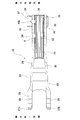
- FIG. 1 is a perspective view showing a torque transmission shaft according to a first example of the embodiment.
- FIG. 2 is an exploded perspective view showing a torque transmission shaft according to a first example of the embodiment.
- FIG. 3 is an end view showing the torque transmission shaft according to the first example of the embodiment as viewed from the other side in the axial direction.
- FIG. 4 is a cross-sectional view taken along line AA of FIG.
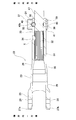
- FIG. 5 is a plan view showing a shaft of a torque transmission shaft according to a first example of the embodiment.
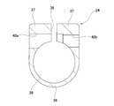
- FIG. 6 is a cross-sectional view showing a clamp of a torque transmission shaft according to a first example of the embodiment.
- FIG. 1 is a perspective view showing a torque transmission shaft according to a first example of the embodiment.
- FIG. 2 is an exploded perspective view showing a torque transmission shaft according to a first example of the embodiment.
- FIG. 3 is an end view showing the torque transmission shaft according to the first example of the embodiment as viewed from the other side in the
- FIG. 7 is an exploded perspective view showing a torque transmission shaft and a shaft connected to the torque transmission shaft according to a first example of the embodiment.
- FIG. 8 is a cross-sectional view showing a connected state of a torque transmission shaft and a shaft connected to the torque transmission shaft according to a first example of the embodiment.
- FIG. 9 is an end view showing a clamp of a torque transmission shaft according to a second example of the embodiment.
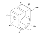
- FIG. 10 is a perspective view showing a clamp of a torque transmission shaft according to a second example of the embodiment.
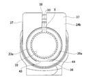
- FIG. 11 is an end view showing a torque transmission shaft according to a third example of the embodiment as viewed from the other side in the axial direction.
- FIG. 12 is a perspective view showing a clamp of a torque transmission shaft according to a third example of the embodiment.
- FIG. 13 is a plan view showing a shaft of a torque transmission shaft according to a fourth example of the embodiment.
- FIG. 14 is a cross-sectional view showing a connected state of a torque transmission shaft and a shaft connected to the torque transmission shaft according to a fifth example of the embodiment.
- FIG. 15 is a plan view showing a shaft of a torque transmission shaft according to a fifth example of the embodiment.
- FIG. 16 is a partial cross-sectional view showing a shaft of a torque transmission shaft according to a fifth example of the embodiment.
- FIG. 17 is an end view showing a shaft of a torque transmission shaft according to a fifth example of the embodiment as viewed from the other side in the axial direction.
- FIG. 18 is a plan view showing a shaft of a torque transmission shaft according to a sixth example of the embodiment.
- FIG. 19 is a cross-sectional view showing a connected state of a torque transmission shaft and a shaft connected to the torque transmission shaft according to a seventh example of the embodiment.
- FIG. 20 is a cross-sectional view showing a connected state of a torque transmission shaft and a shaft connected to the torque transmission shaft according to an eighth example of the embodiment.
- FIG. 21 is a partial cross-sectional side view showing a conventional steering apparatus.
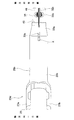
- FIG. 22 (A) is a perspective view showing a structure in which the yoke and the rotating shaft are connected by a torque transmission shaft, which the present inventors previously considered
- FIG. 22 (B) is a diagram of FIG. 22 (C) is a schematic view for explaining a state in which swinging occurs in the shaft connected to the torque transmission shaft in the structure shown in FIG. 22 (A). is there.
- the torque transmission shaft 22 in this example is, for example, a rotation shaft which is incorporated in the steering apparatus of a large car and is not coaxial with each other, between the steering shaft and the intermediate shaft or the intermediate shaft and the pinion shaft Are used to connect in a torque transmittable manner.
- the torque transmission shaft 22 is provided with a hollow cylindrical shaft 23 and a not-cylindrical (substantially U-shaped) clamp 24 which are formed separately from each other.
- the axial direction refers to the axial direction of the torque transmission shaft 22 unless otherwise specified.
- the one end side in the axial direction means the side on which the yoke portion 25 exists, and is the left end side in FIGS. 1, 2, 4, 5, 7 and 8.
- the other end side in the axial direction means the side on which the clamp 24 is disposed, and is the right end side in FIGS. 1, 2, 4, 5, 7 and 8.
- the shaft 23 is integrally formed by subjecting a material such as a carbon steel cast steel (SC material) or the like to forging (cold forging or hot forging), cutting, and the like.
- SC material carbon steel cast steel
- the shaft 23 is provided with a bifurcated yoke portion 25 at one end in the axial direction, and a cylindrical portion 26 at the other end in the axial direction and the middle portion.
- the yoke portion 25 constitutes a universal joint of cross-shaft type, and includes a pair of arm portions 27a and 27b.
- the arm portions 27 a and 27 b extend from one of two positions on the opposite side in the diameter direction of one axial end of the cylindrical portion 26 to one side in the axial direction.
- Each of the arms 27a, 27b has a circular hole 28 coaxial with each other. Inside each of the circular holes 28, a bearing cup and a needle (not shown) for rotatably supporting a shaft portion constituting a cross shaft are arranged.
- the cylinder part 26 which comprises the shaft 23 is hollow cylinder shape as a whole, and is provided with the large diameter cylinder part 29, the conical cylinder part 30, and the small diameter cylinder part 31 sequentially from one axial direction side.
- the large diameter cylindrical portion 29 has a stepped cylindrical shape, and the other axial end of the large diameter cylindrical portion 29 is connected to one axial end of the conical cylindrical portion 30.
- the outer diameter size and the inner diameter size of the large diameter cylindrical portion 29 are larger than the outer diameter size and the inner diameter size of the small diameter cylindrical portion 31.
- the conical cylinder portion 30 has a partially conical cylindrical shape, and the outer diameter dimension and the inner diameter dimension of the conical cylinder portion 30 decrease toward the other side in the axial direction.
- the other axial end of the conical cylindrical portion 30 is connected to one axial end of the small diameter cylindrical portion 31.
- the small diameter cylindrical portion 31 has a cylindrical shape, and is disposed in a range extending from the axially intermediate portion of the shaft 23 to the other axial end portion.
- the outer peripheral surface of the small diameter cylindrical portion 31 is a cylindrical surface whose outer diameter dimension does not change in the axial direction, whereas the inner peripheral surface of the small diameter cylindrical portion 31 is provided with female serrations 32 over the entire length thereof.
- the end of a shaft 47 such as a steering shaft or a pinion shaft is inserted inside the small diameter cylindrical portion 31 and is formed on the outer peripheral surface of the shaft 47 with respect to the female serration 32.
- a male serration 48 engages the serration.
- the small diameter cylindrical portion 31 includes a slit 33 extending in the axial direction at a portion where the circumferential position (phase) of the small diameter cylindrical portion 31 coincides with one of the arm portions 27 a constituting the yoke portion 25.
- the slits 33 communicate the inner peripheral surface and the outer peripheral surface of the small diameter cylindrical portion 31.
- One end in the axial direction of the slit 33 that is, the back end X, is located at an axially intermediate portion of the small diameter cylindrical portion 31, and the other axial end of the slit 33 is in the small diameter cylindrical portion 31 (shaft 23). It is open at the other end in the axial direction.
- the deep end portion X of the slit 33 has a stress relaxation portion 34 having a larger width than the portion adjacent to the other side in the axial direction and having a substantially circular opening shape (see FIG. 5) in plan view It is done.
- the slit 33 at the other axial end of the shaft 23, the other axial end of the shaft 23 (the other half of the small diameter cylindrical portion 31 in the axial direction) can be reduced in diameter.
- the stress relieving portion 34 at the far end X of the slit 33 it is possible to prevent damage such as a crack from occurring at the far end X of the slit 33 where stress is easily concentrated when reducing the diameter of the shaft 23. Be done.
- the shaft 23 is located on the outer peripheral surface of the portion of the small diameter cylindrical portion 31 near the other end in the axial direction with respect to the central axis of the shaft 23 at a portion where the circumferential position coincides with one arm portion 27 a constituting the yoke portion 25. It further comprises an engaging recess 35 extending in the orthogonal direction. That is, the engagement concave groove 35 is formed to intersect the slit 33.
- the crossing portion between the engagement concave groove 35 and the slit 33 is a wide portion whose width dimension is larger than the portion of the slit 33 adjacent to both sides in the axial direction of the crossing portion.
- the engagement concave groove 35 is formed in a partial cylindrical surface shape, and the radius of curvature thereof is substantially the same as the radius of curvature of the mounting hole 40 a (40 b) formed in the clamp 24.
- the clamp 24 is externally fitted to the other axial end of the shaft 23 and has a function of reducing the diameter of the other axial end of the shaft 23. Specifically, the clamp 24 is externally fitted to the other end of the small diameter cylindrical portion 31 of the shaft 23 in the axial direction to reduce the diameter of the other half of the small diameter cylindrical portion 31 in the axial direction.
- the clamp 24 is a carbon steel for machine structure by subjecting a material such as S35C, which is a carbon steel for machine structure, to a hardness higher than that of the material constituting the shaft 23 by hot forging or cutting, etc. It is made by subjecting a material such as S10C or S15C to cold forging which causes work hardening.
- the clamp 24 is entirely cylindrical (substantially U-shaped), and has a semi-cylindrical base 36 and a pair of substantially rectangular plate-shaped flanges disposed on both ends of the base 36 in the circumferential direction. 37 and discontinuities 38 provided at one circumferential direction located between the pair of flanges 37. In other words, the pair of flanges 37 is disposed on both sides of the discontinuity 38.
- the width dimension of the discontinuous portion 38 in the free state of the clamp 24 and the width dimension of the slit 33 in the free state of the shaft 23 (small diameter cylindrical portion 31) are the same.
- the thickness dimensions of the pair of flanges 37 are the same.
- the clamp 24 has an insertion hole 39 for inserting the small diameter cylindrical portion 31 of the shaft 23.
- the insertion hole 39 has a notched cylindrical surface formed by the inner circumferential surface of the base portion 36 and the radially inner side surface of the pair of flange portions 37.
- the inner diameter of the insertion hole 39 is equal to or slightly larger than the outer diameter of the small diameter cylindrical portion 31 in the free state of the clamp 24.
- the pair of flanges 37 are provided with coaxial mounting holes 40a and 40b at the portions aligned with each other.
- Each of the mounting holes 40 a and 40 b is formed in a twisted position with respect to the central axis of the insertion hole 39, and opens in the insertion hole 39.
- one mounting hole 40a is a through hole
- the other mounting hole 40b is a screw hole.
- the tightening bolt 49 which is a tightening member is inserted inside the pair of mounting holes 40a and 40b, and , And disposed inside the engagement concave groove 35.
- the proximal end portion of the tightening bolt 49 is inserted into the inside of one mounting hole 40 a which is a through hole, and the middle portion of the tightening bolt 49 is the inside of the engagement concave groove 35. Will be placed.
- the tip end portion of the tightening bolt 49 is screwed into the other mounting hole 40b which is a screw hole, that is, only to the extent that the small diameter cylindrical portion 31 is not contracted.
- the shaft 23 and the clamp 24 are fixed by welding. Specifically, in a portion between the opening edge on one side in the axial direction of the insertion hole 39 of the clamp 24 and the outer peripheral surface of the shaft 23, one circumferential direction opposite to the slit 33 in the diameter direction of the shaft 23
- the shaft 23 and the clamp 24 are fixed by welding by forming the welded portion 41 by spot welding.
- the welding portion 41 is formed on the side opposite to the slit 33 in the diametrical direction of the shaft 23, the pair of flange portions 37 at the time of clamping is provided due to the provision of the welding portion 41. It is possible to prevent the influence of the amount of bending (the balance of the amount of bending becomes worse).
- the other axial end of the shaft 23 is inserted into the insertion hole 39 of the clamp 24 from one side in the axial direction.
- the circumferential positions of the discontinuous portion 38 of the clamp 24 and the slit 33 of the shaft 23 are made to coincide with each other.
- a plate-like phasing member is inserted inside the portion 38 and the slit 33.
- the shaft 23 and the clamp 24 are relatively moved in the axial direction until the axial positions of the pair of mounting holes 40a, 40b and the engagement concave groove 35 coincide with each other.
- the yoke portion 25 disposed at one axial end of the torque transmission shaft 22 is combined with another yoke and a cross shaft (not shown).
- the torque transmission shaft 22 is connected in a torque transmittable manner to an axis such as an intermediate shaft provided with another yoke.
- a shaft 47 such as a steering shaft or a pinion shaft is inserted inside the small diameter cylindrical portion 31 and a male serration 48 formed on the outer peripheral surface of the shaft 47 is formed on the inner peripheral surface of the small diameter cylindrical portion 31 The serration is engaged with the female serration 32.
- relative rotation between the torque transmission shaft 22 and the shaft 47 is prevented.
- a tightening bolt is provided through a wide portion which is an intersection of the engagement groove 35 and the slit 33 inside an annular groove 50 disposed on the outer peripheral surface of the tip of the shaft 47 so as to cross the male serration 48 in the circumferential direction.
- the intermediate portion 49 enters and key-engages the annular recess 50 and the clamping bolt 49.
- the width dimension of the discontinuous portion 38 becomes smaller, and the diameter of the small diameter cylindrical portion 31 is reduced.
- the outer peripheral surface of the shaft 47 is strongly tightened.
- the torque transmission shaft 22 and the shaft 47 such as a steering shaft or a pinion shaft are coupled in a torque transmittable manner.
- the clamp 24 is not integral with the shaft 23, but is welded and fixed to the shaft 23.
- positioned at the axial direction both ends of the shaft 23 is ensured highly.
- the shaft 23 and the yoke portion 25 are not separately welded and fixed but are integrally formed. For this reason, the influence of the thermal deformation at the time of welding is not required, and the coaxiality of the yoke portion 25 with respect to the shaft 23 (the cylindrical portion 26) is secured high.
- the clamp 24 a has a protrusion 42 that protrudes radially inward on a part of the inner peripheral surface of the insertion hole 39.
- the protrusion 42 has a function of preventing the clamp 24 a from rotating relative to the shaft 23 before welding the clamp 24 a to the other axial end of the shaft 23 (see FIG. 1).
- the protrusion 42 has a substantially triangular cross-sectional shape, and is disposed on the side of the inner peripheral surface of the insertion hole 39 opposite to the discontinuous portion 38 in the diameter direction of the insertion hole 39. Further, the protrusion 42 extends over the entire axial width of the insertion hole 39.
- the shaft 23a has a flat shaft side flat portion 43 on the side of the outer peripheral surface of the other axial end opposite to the slit 33 in the diameter direction of the shaft 23. Therefore, the contour of the outer peripheral surface of the other axial end of the shaft 23a is substantially D-shaped, which includes an arc portion and a straight portion.
- the clamp 24b has a flat-surfaced clamp side flat portion 44 on the side of the inner peripheral surface of the insertion hole 39a opposite to the discontinuous portion 38 in the diameter direction of the insertion hole 39a. Therefore, the contour of the inner peripheral surface of the insertion hole 39a of the clamp 24b is also substantially D-shaped, which is composed of an arc portion and a straight portion.
- the flat-side shaft-side flat portion 43 and the flat-side clamp-side flat portion 44 face each other.
- the outer peripheral surface of the shaft 23a and the inner peripheral surface of the insertion hole 39a of the clamp 24b are non-circularly fitted to prevent relative rotation between the shaft 23a and the clamp 24b.
- the other configuration and operational effects are the same as those of the first example of the embodiment, including that the shaft 23a and the clamp 24b are fixed by welding.
- the shaft 23b has a substantially annular (C-shaped) step facing the other side in the axial direction toward the other axial end portion of the outer peripheral surface (the axial intermediate portion of the outer peripheral surface of the small diameter cylindrical portion 31). It has a face 45.
- the other end of the small diameter cylindrical portion 31 in the axial direction is provided with a fitting cylindrical portion 46 whose outer diameter is smaller than a portion adjacent to one side in the axial direction, and the step surface 45
- the cylindrical portion 46 is disposed at one end in the axial direction.
- the fitting cylindrical portion 46 is formed by cutting the outer peripheral surface of the other end of the small diameter cylindrical portion 31 in the axial direction.
- the clamp 24 see FIG. 1
- the axial end of the clamp 24 abuts against the step surface 45 to position the clamp 24 relative to the shaft 23b in the axial direction. It is possible.
- the other configuration and operational effects are the same as those of the first example of the embodiment, including that the shaft 23 b and the clamp 24 are fixed by welding.
- the cylindrical portion 26a of the shaft 23c includes, in order from one axial side, a large diameter cylindrical portion 29a, a large diameter side conical cylindrical portion 51, an intermediate diameter cylindrical portion 52, and a small diameter side conical cylindrical portion 53; It is comprised from the small diameter cylinder part 31a.
- the large diameter cylindrical portion 29a is disposed at one axial end of the cylindrical portion 26a.
- the other axial end of the large diameter cylindrical portion 29 a is connected to the one axial end of the large diameter side conical cylindrical portion 51.
- the outer diameter size and the inner diameter size of the large diameter cylindrical portion 29a are larger than the outer diameter size and the inner diameter size of the other portion constituting the cylindrical portion 26a, which is present on the other axial side of the large diameter cylindrical portion 29a. That is, the large diameter cylindrical portion 29a has the largest outer diameter dimension and inner diameter dimension in the cylindrical portion 26a.
- the large diameter side conical cylinder portion 51 has a partially conical cylindrical shape in which the outer diameter dimension and the inner diameter dimension decrease toward the other side in the axial direction.
- the other axial end of the large diameter side conical cylinder portion 51 is , And is connected to one axial end of the middle diameter cylindrical portion 52.
- the medium diameter cylindrical portion 52 is disposed at an axially intermediate portion of the cylindrical portion 26a.
- the outer diameter dimension and the inner diameter dimension of the medium diameter cylindrical portion 52 are constant in the axial direction. Further, the other axial end of the medium diameter cylindrical portion 52 is connected to one axial end of the small diameter side conical cylindrical portion 53.
- the small-diameter side conical cylinder portion 53 has a partially conical cylindrical shape in which the outer diameter dimension and the inner diameter dimension decrease toward the other side in the axial direction.
- the other axial end of the small diameter side conical cylindrical portion 53 is connected to one axial end of the small diameter cylindrical portion 31a.
- the small diameter cylindrical portion 31a is disposed at the other axial end of the cylindrical portion 26a and has a substantially cylindrical shape.
- the small diameter cylindrical portion 31a is formed by drawing the other end in the axial direction of the cylindrical portion 26a.
- the outer diameter size and the inner diameter size of the small diameter cylindrical portion 31a are smaller than the outer diameter size and the inner diameter size of the other portion of the small diameter cylindrical portion 31a which constitutes the cylindrical portion 26a. That is, the small diameter cylindrical portion 31a has the smallest outer diameter dimension and inner diameter dimension in the cylindrical portion 26a.
- a substantially annular (C-shaped) stepped surface 45 facing the other side in the axial direction is provided at an axially intermediate portion of the outer peripheral surface of the small diameter cylindrical portion 31a.
- the diameter direction of the shaft 23c is welded and fixed by forming a weld portion 41 by spot welding at one circumferential direction opposite to the slit 33.
- the inner peripheral surface of the small diameter cylindrical portion 31a is provided with a female serration 32a which extends over the entire length of the small diameter cylindrical portion 31a.
- female serrations 32a are provided only on the inner peripheral surface of the small diameter cylindrical portion 31a among the inner peripheral surfaces of the cylindrical portion 26a.
- the female serration 32a has an incomplete serration portion 55 at one end in the axial direction, in which the groove depth (inner diameter) of the female serration groove constituting the female serration 32a decreases toward the one axial side. As shown in FIG.
- a shaft 47 such as a steering shaft or a pinion shaft is inserted inside the small diameter cylindrical portion 31a, and a male serration 48 formed on the outer peripheral surface of the shaft 47 is a female serration 32a.
- the incomplete serration portion 55 has a structure that does not smoothly engage with the male serrations 48.
- the step surface 45 is disposed at the axially intermediate portion of the outer peripheral surface of the small diameter cylindrical portion 31a, by abutting the clamp 24 against the step surface 45, the axial direction of the clamp 24 with respect to the shaft 23c can be obtained.
- the incomplete serration portion 55 is positioned on one side in the axial direction with respect to one axial end surface of the clamp 24. Furthermore, the welding portion 41 is present between the incomplete serration portion 55 and one axial end face of the shaft 47 in the axial direction. For this reason, in the female serration 32a, the portion of the female serration engaged with the male serration 48 of the shaft 47 is prevented from being thermally deformed by welding, and the clamp 24 and the shaft 47 can be smoothly coupled.
- an axially extending slit 33a is provided in a range from the medium diameter cylindrical portion 52 to the small diameter cylindrical portion 31a, which is located at the axially middle portion of the cylindrical portion 26a as described above to the other axial end. ing.
- the back end X which is one axial end of the slit 33a, is located at the other axial end of the medium diameter cylindrical portion 52 present on one side in the axial direction of the small diameter cylindrical portion 31a, and the axial direction of the slit 33a
- the other end edge portion is opened at the other end edge in the axial direction of the small diameter cylindrical portion 31a (shaft 23c).
- an axial one side portion which is a portion adjacent to the other axial side of the deep end portion X is located in the small diameter side conical cylindrical portion 53.
- the female serration 32a is not provided in the inner peripheral surface of the part in which the back end part X of the slit 33a is located among the cylinder parts 26a. Therefore, the deep end portion X of the slit 33a is located on one side in the axial direction with respect to one axial end of the female serration 32a.
- the stress relaxation portion 34 (see FIG. 1 and the like) is not provided at the deep end portion X of the slit 33a, and the width dimension of the slit 33a in the circumferential direction is constant over the entire length.
- a slit 33a is formed by cutting using a rotary cutting tool such as a cutter.
- the cross-sectional shape of the deep end portion X (one end edge in the axial direction) of the slit 33a is a partial arc shape.
- the stress relaxation portion 34 having a larger width dimension than the portion adjacent to the other side in the axial direction may be provided at the deep end portion X of the slit 33 a.
- the slit 33a is disposed at a position 90 degrees out of phase with the pair of arm portions 27a and 27b constituting the yoke portion 25.
- the non-toothed portion 54 in which the female serration 32a is not formed is provided in a portion adjacent to both sides of the slit 33a in the circumferential direction in the inner peripheral surface of the small diameter cylindrical portion 31a. That is, the non-toothed portion 54 has a partial cylindrical surface having an inner diameter dimension substantially the same as the inscribed circle diameter of the valley portion of the female serration 32a.
- the back end X of the slit 33a is located in the medium diameter cylindrical portion 52 having a larger outer diameter and inner diameter than the small diameter cylindrical portion 31a, the diameter of the other end of the shaft 23c in the axial direction is reduced.
- the stress generated at the back end X of the slit 33a can be made smaller than in the case where the back end is positioned at the small diameter cylindrical portion 31a.
- the female serration 32a does not exist on one side in the axial direction with respect to the deep end X of the slit 33a, the deep end X of the slit 33a and the valley of the female serration 32a are axially continuous.
- the processing for forming the stress relieving portion at the deep end X of the slit 33a can be omitted, so that the processing cost of the slit 33a can be suppressed. Furthermore, since it is not necessary to deburr the deep end portion of the slit 33a, the processing cost can be suppressed also from this aspect.
- the toothless portion 54 is provided in a portion positioned on both sides of the slit 33a in the circumferential direction in the inner peripheral surface of the small diameter cylindrical portion 31a, the other end of the shaft 23c in the axial direction is reduced in diameter
- the male serration 48 formed on the outer peripheral surface of the shaft 47 is prevented from being hit locally. Therefore, it is possible to prevent the occurrence of cracking or chipping of serrated teeth due to excessive stress concentration, which may be a problem when female serrations are formed on both sides in the circumferential direction of the slit 33a.
- the cylindrical portion 26a has a three-step structure including a small diameter cylindrical portion 31a, a medium diameter cylindrical portion 52, and a large diameter cylindrical portion 29a. Therefore, the shaft 23c is fabricated by forging a metal material, as in the first example of the embodiment, a two-step structure having the small diameter cylindrical portion 31 and the large diameter cylindrical portion 29 as the cylindrical portion 26.
- the shaft 23 can be made easier as compared to the case where it is manufactured by forging.
- the cylindrical portion 26 has a three-stage structure, and the female serrations 32a are provided only on the inner peripheral surface of the small diameter cylindrical portion 31a.
- the cylindrical portion 26 has a two-step structure, and the shaft on the inner peripheral surface of the small diameter cylindrical portion 31 of the cylindrical portion 26
- the axial length of the female serration 32a can be reduced as compared to the shaft 23 in which the female serration 32 is provided in the direction. Therefore, in the shaft 23c of this example, the processing cost when forming the female serration 32a by broaching, pressing, etc. is suppressed as compared with the shaft 23 in the first example of the embodiment.
- Other configurations and effects are the same as the first example of the embodiment.
- the cylindrical portion 26b of the shaft 23d has a two-step structure in which the small diameter cylindrical portion 31b and the large diameter cylindrical portion 29b are connected by the conical cylindrical portion 30a.
- the axial length of the small diameter cylindrical portion 31b is shorter than the axial length of the small diameter cylindrical portion 31 of the shaft 23 in the first example of the embodiment.
- the shaft 23d has the axial position of the conical cylindrical portion 30a on the other side in the axial direction of the axial position of the conical cylindrical portion 30 in the shaft 23 of the first example of the embodiment.
- the axial length of the female serration 32b formed on the inner peripheral surface of the small diameter cylindrical portion 31b is made shorter than the axial length of the female serration 32 in the first example of the embodiment, and the female serration 32b is obtained.
- the processing cost at the time of forming is suppressed.
- the back end X which is one axial end of the slit 33a is located at the other axial end of the large diameter cylindrical portion 29b.
- an axial direction one side portion which is a portion adjacent to the other side in the axial direction of the back end portion X is located in the conical cylindrical portion 30a.
- a substantially annular step surface 45 facing the other side in the axial direction is present at an axially intermediate portion of the outer peripheral surface of the small diameter cylindrical portion 31b.
- the axial position of the step surface 45a is located on one side in the axial direction relative to the structure of the fifth example of the embodiment. Therefore, the axial length of the fitting cylinder 46 a is longer than the axial length of the fitting cylinder 46 of the fifth example of the embodiment.
- the axial position of the step surface 45a coincides with the axial position of the incomplete serration portion 55 disposed at one axial end of the female serration 32a. That is, the step surface 45 a is located radially outward of the incomplete serration portion 55.
- the axial length of the clamp 24c is also equal to the axial length of the fitting cylindrical portion 46a being longer than the axial length of the fitting cylindrical portion 46 of the fifth example of the embodiment.
- the axial length of the clamp 24 in the fifth example of the embodiment is longer.
- the diameter direction of the shaft 23e in the portion between the opening edge on one axial side of the insertion hole 39 of the clamp 24a and the outer peripheral surface of the shaft 23e are welded and fixed by forming the welding portion 41 by spot welding at one circumferential direction opposite to the slit 33 with respect to the angle.
- the step surface 45 is located radially outward of the incomplete serration portion 55, the axial position of the weld portion 41 coincides with the axial position of the incomplete serration portion 55. That is, the welding portion 41 is located radially outward of the incomplete serration portion 55.
- the welding portion 41 is located radially outward of the incomplete serration portion 55 which is not in serration engagement with the male serration 48 of the shaft 47, the male serration 48 of the shaft 47 among the female serrations 32a.
- the portion engaged with the serration is prevented from being thermally deformed by welding, and the clamp 24c and the shaft 47 are smoothly coupled.
- the axial length of the fitting cylinder 46a is longer than the axial length of the fitting cylinder 46 of the fifth example of the embodiment, the fitting length between the shaft 23e and the clamp 24c Is sufficiently secured, and the fitting strength can be stabilized.
- the other configuration and effects are the same as the first and fifth examples of the embodiment.
- the shaft 23f of this example has a stress relief portion 34 at the far end X of the slit 33, like the shaft 23 of the first example of the embodiment. Further, as with the shaft 23c of the fifth example of the embodiment, the shaft 23f is provided with the non-toothed portion 54 in the portion positioned on both sides of the slit 33 in the circumferential direction on the inner peripheral surface of the small diameter cylindrical portion 31. ing. As a result, when the diameter of the other axial end portion of the shaft 23f is reduced, it is possible to prevent the male serration 48 formed on the outer peripheral surface of the shaft 47 from local contact. Other configurations and effects are the same as the first example and the fifth example of the embodiment, including that the shaft 23 e and the clamp 24 are fixed by welding.
- the circumferential position of the slit provided on the shaft is not limited to the position shown in each example of the embodiment.
- the number of slits is not limited to one, and a plurality of slits can also be provided.
- the shape of the stress relieving portion formed at the back end of the slit is not limited to the shape shown in each example of the embodiment, and an arbitrary shape such as an elliptical shape or a droplet shape may be employed.
- the pair of mounting holes provided in the clamp can be used as through holes, respectively, and can be used in combination with the nut.
- the shaft and the clamp may be fixed immovably in the axial direction by press-fitting the shaft to the clamp (light press-fit) instead of welding and fixing the shaft and the clamp.
- the structures of the respective embodiments can be implemented in combination as appropriate.
- the structure of the second or third embodiment capable of preventing relative rotation between the shaft and the clamp and the structure of the fourth embodiment capable of axially positioning the clamp with respect to the shaft can be simultaneously implemented. can do.
Landscapes
- Engineering & Computer Science (AREA)
- General Engineering & Computer Science (AREA)
- Mechanical Engineering (AREA)
- Ocean & Marine Engineering (AREA)
- Chemical & Material Sciences (AREA)
- Combustion & Propulsion (AREA)
- Transportation (AREA)
- Shafts, Cranks, Connecting Bars, And Related Bearings (AREA)
- Steering Controls (AREA)
Abstract
トルク伝達軸に接続される軸の振れ回りを抑えることができるトルク伝達軸の構造を実現する。トルク伝達軸22は、一体に形成され、かつ、軸方向一端部に備えられたヨーク部25と、軸方向他端部の内周面に備えられた雌セレーション32とを有する、シャフト23と、シャフト23とは別体で、シャフト23の軸方向他端部を縮径させるためのクランプ24とを備え、シャフト23とクランプ24とが溶接固定されている。
Description
本発明は、自動車用のステアリング装置などに組み込まれるトルク伝達軸に関する。
図21は、特開2017-25964号公報に記載され、従来から知られた自動車用のステアリング装置を示している。ステアリング装置は、ステアリングホイール1と、ステアリングシャフト2と、ステアリングコラム3と、1対の自在継手4a、4bと、中間シャフト5と、ステアリングギヤユニット6と、および、1対のタイロッド7とを備える。
ステアリングホイール1は、ステアリングコラム3の内側に回転自在に支持されたステアリングシャフト2の後端部に取り付けられている。ステアリングシャフト2の前端部は、1対の自在継手4a、4bおよび中間シャフト5を介して、ステアリングギヤユニット6のピニオン軸8に接続されている。そして、ピニオン軸8の回転を図示しないラックの直線運動に変換することで、1対のタイロッド7を押し引きし、操舵輪にステアリングホイール1の操作量に応じた舵角が付与される。なお、前後方向とは、ステアリング装置が組み付けられる車体の前後方向をいう。
自在継手4a、4bは、互いに同一直線上に存在しない回転軸である、ステアリングシャフト2と中間シャフト5との間、並びに、中間シャフト5とピニオン軸8との間を、互いにトルク伝達可能に接続するものである。自在継手4a、4bとしては、特開2011-220398号公報などに記載されている、1対のヨークと十字軸とを備えた十字軸式の自在継手が使用されている。
ところで、大型の自動車に搭載されるステアリング装置では、ステアリングシャフトからステアリングギヤユニットまでの距離が長くなる。このため、自在継手を構成するヨークに対して、ステアリングシャフトやピニオン軸などの軸を直接固定せずに、エクステンションシャフト(延長軸)とも呼ばれるトルク伝達軸を介して固定することが考えられている。
図22(A)~図22(C)は、本発明者らが先に考えたトルク伝達軸9を示している。トルク伝達軸9は、ヨーク10と、ステアリングシャフトやピニオン軸などの軸11との間に配置され、ヨーク10と軸11との間をトルク伝達可能に接続する。また、トルク伝達軸9は、軸方向一端部の外周面に雄セレーション12を有し、かつ、軸方向他端部の内周面に雌セレーション13を有する。トルク伝達軸9の軸方向他端部には、トルク伝達軸9の軸方向他端部を縮径するためのクランプ部14が一体に設けられている。具体的には、トルク伝達軸9の軸方向他端部の円周方向1箇所に不連続部15が形成されており、不連続部15の両側に1対のフランジ部16が配置されている。フランジ部16のそれぞれは、図示しない締付部材を挿入するための取付孔17を有する。
トルク伝達軸9の軸方向一端部は、ヨーク10を構成する基部18の内側に挿入され、雄セレーション12は、基部18の内周面に形成された雌セレーション19とセレーション係合する。また、トルク伝達軸9と基部18との間は、溶接ビード部20により全周にわたって溶接固定されている。
トルク伝達軸9の軸方向他端部の内側には、軸11の軸方向一端部が挿入され、雌セレーション13は、軸11の外周面に形成された雄セレーション21とセレーション係合する。締付部材の先端部を取付孔17または図示しないナットに螺合することで、トルク伝達軸9の内周面により軸11の外周面は強く締め付けられる。
トルク伝達軸9は、冷間鍛造加工により造られる場合が多く、熱間鍛造加工により造られる場合に比べて、形状精度および寸法精度は高いが、金属材料の流動が複雑になるクランプ部14が一体に設けられていることなどに起因して、トルク伝達軸9の軸方向両端部に設ける雄セレーション12と雌セレーション13との同軸度を高度に確保することが難しくなる。また、トルク伝達軸9とヨーク10とを溶接固定しているため、熱変形などに起因して、トルク伝達軸9とヨーク10との同軸度が低くなりやすい。このため、図22(C)に示すように、トルク伝達軸9に接続される軸、すなわちヨーク10を介して接続される軸11aまたは雌セレーション13に接続される軸11の振れ回りが大きくなる可能性がある。この結果、ステアリング装置の一部で、軸の振れ回りに起因した、回転方向の摺動異音、スティックスリップ振動異音などの異音を発生させる可能性がある。
本発明は、上述のような事情に鑑みて、トルク伝達軸に接続される軸の振れ回りを抑えることを可能とする構造を有する、トルク伝達軸を提供することを目的とする。
本発明のトルク伝達軸は、シャフトと、クランプとを備える。
前記シャフトは、中空状で、軸方向一端部に備えられたヨーク部と、軸方向他端部に備えられ、軸方向に伸長するスリットと、前記軸方向他端部の内周面に備えられた雌セレーションと、を有する。前記ヨーク部は、該シャフトと一体である。一方、前記クランプは、前記シャフトとは別体である。
前記クランプは、欠円筒状であり、円周方向1箇所に配置された不連続部と、該不連続部を挟んで円周方向の両側に配置され、かつ、締付部材が挿入される取付孔をそれぞれ有する1対のフランジ部と、を有する。前記クランプは、前記シャフトの前記軸方向他端部に外嵌されて、前記不連続部の幅寸法を狭めることにより、前記シャフトの前記軸方向他端部を縮径させる。
本発明では、たとえば前記シャフトと前記クランプとが溶接固定されることにより、前記シャフトと前記クランプとが、軸方向に移動不能に固定されている。この場合、前記雌セレーションは、軸方向一端部に、軸方向一方側に向かうほど雌セレーション溝の溝深さが小さくなる不完全セレーション部を有し、前記シャフトと前記クランプとの溶接固定部を、前記不完全セレーション部の外径側に位置させることができる。
あるいは、前記クランプに対して前記シャフトを圧入(軽圧入)することにより、前記シャフトと前記クランプとを、軸方向に移動不能に固定することができる。
前記スリットは、軸方向一端部、すなわち奥端部に、軸方向他方側に隣接する部分に比べて大きい幅寸法を有する応力緩和部を備えることができる。前記応力緩和部は、たとえば、平面視で円形状、楕円形状、滴形状などの形状を有し、かつ、凹曲面からなる内面を有することができる。
あるいは、前記スリットの前記軸方向一端部、すなわち奥端部は、前記雌セレーションの軸方向一端縁よりも軸方向一方側に位置することができる。この場合、前記シャフトは、前記軸方向他端部に小径筒部を有し、前記雌セレーションは、前記小径筒部の内周面にのみ設けられており、前記スリットの前記軸方向一端部、すなわち奥端部は、前記小径筒部よりも軸方向一方側に存在し、かつ、前記小径筒部よりも外径寸法および内径寸法が大きい部分に、位置することができる。さらに、前記シャフトは、前記小径筒部の軸方向一方側に隣接する部分に、軸方向一方側に向かうほど外径寸法および内径寸法が大きくなる円すい筒部を有し、前記スリットの前記軸方向一端部は、前記円すい筒部よりも軸方向一方側に位置することができる。
前記シャフトは、前記内周面のうちで、円周方向に関して前記スリットの両側に隣接する部分に、前記雌セレーションが設けられていない欠歯部を有することができる。
前記シャフトは、外周面のうちで、前記取付孔のそれぞれの開口部と対向する部分に、前記シャフトの中心軸に直交する方向に伸長し、かつ、その内側に前記締付部材が配置される係合凹溝を有することができる。
前記スリットと前記不連続部との円周方向位置を互いに一致させ、かつ、前記シャフトおよび前記クランプの自由状態での前記スリットの幅寸法と前記不連続部の幅寸法とを互いに同じにすることができる。
前記クランプは、前記シャフトよりも高い硬度を有し、かつ、前記クランプのうちで前記シャフトが挿入される挿入孔の内周面に設けられ、前記シャフトの外周面に食い込む突起部を有することができる。
前記突起部は、前記挿入孔の内周面のうちで、前記挿入孔の直径方向に関して前記不連続部とは反対側部分に配置されることができる。
前記シャフトの外周面と、前記クランプのうち前記シャフトが挿入される挿入孔の内周面とは、相対回転不能に非円形嵌合することができる。
この場合、前記シャフトは、外周面の少なくとも円周方向一部と、前記挿入孔の内周面の少なくとも円周方向一部とに、平面部(直線部)を有することができる。
前記シャフトは、外周面に、軸方向他方側を向いた段差面を有し、前記段差面に対し前記クランプを突き当てることで、前記シャフトに対する前記クランプの軸方向に関する位置決めを図ることができる。
本発明のトルク伝達軸により、該トルク伝達軸に接続される軸の振れ回りを効果的に抑えることが可能となる。
[実施の形態の第1例]
本発明の実施の形態の第1例について、図1~図8を用いて説明する。本例のトルク伝達軸22は、たとえば大型の自動車のステアリング装置に組み込まれて、互いに同一直線上に存在しない回転軸である、ステアリングシャフトと中間シャフトとの間、または、中間シャフトとピニオン軸との間を、トルク伝達可能に接続するために使用される。
本発明の実施の形態の第1例について、図1~図8を用いて説明する。本例のトルク伝達軸22は、たとえば大型の自動車のステアリング装置に組み込まれて、互いに同一直線上に存在しない回転軸である、ステアリングシャフトと中間シャフトとの間、または、中間シャフトとピニオン軸との間を、トルク伝達可能に接続するために使用される。
トルク伝達軸22は、互いに別体に構成された、中空筒状のシャフト23と欠円筒状(略U字状)のクランプ24とを備える。なお、以下の説明において、軸方向とは、特に断らない限り、トルク伝達軸22の軸方向をいう。また、軸方向に関して一端側とは、ヨーク部25が存在する側をいい、図1、図2、図4、図5、図7および図8では、左端側である。軸方向に関して他端側とは、クランプ24が配置される側をいい、図1、図2、図4、図5、図7および図8では、右端側である。
シャフト23は、炭素鋼鋳鋼材(SC材)などの素材に、鍛造加工(冷間鍛造加工または熱間鍛造加工)および切削加工などを施すことにより、全体を一体に造られている。シャフト23は、軸方向一端部に二股状のヨーク部25を、軸方向他端部および中間部に筒部26を備える。
ヨーク部25は、十字軸式の自在継手を構成し、1対の腕部27a、27bを備える。腕部27a、27bは、筒部26の軸方向一端縁の直径方向反対側となる2箇所位置から軸方向一方側に伸長している。腕部27a、27bのそれぞれは、互いに同軸の円孔28を有する。円孔28のそれぞれは、内側に、十字軸を構成する軸部を回転自在に支持するための、図示しない軸受カップおよびニードルが配置される。
シャフト23を構成する筒部26は、全体として中空筒状であり、軸方向一方側から順に、大径筒部29と、円すい筒部30と、小径筒部31とを備える。
大径筒部29は、段付円筒状で、大径筒部29の軸方向他端縁は、円すい筒部30の軸方向一端縁につながっている。大径筒部29の外径寸法および内径寸法は、小径筒部31の外径寸法および内径寸法よりも大きくなっている。
円すい筒部30は、部分円すい筒状で、円すい筒部30の外径寸法および内径寸法は、軸方向他方側に向かうほど小さくなる。円すい筒部30の軸方向他端縁は、小径筒部31の軸方向一端縁につながっている。
小径筒部31は、円筒状で、シャフト23の軸方向中間部から軸方向他端部までわたる範囲に配置されている。小径筒部31の外周面は、軸方向にわたり外径寸法が変化しない円筒面状であるのに対して、小径筒部31の内周面は、その全長にわたって雌セレーション32を備える。小径筒部31の内側には、図7および図8に示すように、ステアリングシャフトやピニオン軸などの軸47の端部が挿入され、雌セレーション32に対して、軸47の外周面に形成された雄セレーション48が、セレーション係合する。
小径筒部31は、ヨーク部25を構成する一方の腕部27aと周方向位置(位相)が一致する部分に、軸方向に伸長するスリット33を備える。スリット33は、小径筒部31の内周面と外周面とを連通させる。スリット33の軸方向一端部、すなわち奥端部Xは、小径筒部31の軸方向中間部に位置しており、スリット33の軸方向他端縁部は、小径筒部31(シャフト23)の軸方向他端縁に開口している。スリット33の奥端部Xには、軸方向他方側に隣接する部分に比べて大きい幅寸法を有し、かつ、平面視で略円形の開口形状(図5参照)の応力緩和部34が備えられている。このように、シャフト23の軸方向他端部にスリット33を備えることで、シャフト23の軸方向他端部(小径筒部31の軸方向他半部)は縮径可能に構成される。また、スリット33の奥端部Xに応力緩和部34を備えることで、シャフト23を縮径した際に、応力が集中しやすいスリット33の奥端部Xに亀裂などの損傷が生じることが防止される。
シャフト23は、小径筒部31の軸方向他端寄り部分の外周面のうちで、ヨーク部25を構成する一方の腕部27aと周方向位置が一致する部分に、シャフト23の中心軸に対し直交する方向に伸長した係合凹溝35をさらに備える。すなわち、係合凹溝35は、スリット33と交差するように形成されている。係合凹溝35とスリット33との交差部は、スリット33のうちで交差部の軸方向両側に隣接する部分に比べて幅寸法が大きくなった幅広部となっている。また、係合凹溝35は、部分円筒面状に構成されており、その曲率半径はクランプ24に形成された取付孔40a(40b)の曲率半径とほぼ同じである。
クランプ24は、シャフト23の軸方向他端部に外嵌されて、シャフト23の軸方向他端部を縮径させる機能を有する。具体的には、クランプ24は、シャフト23の小径筒部31の軸方向他端部に外嵌されて、小径筒部31の軸方向他半部を縮径させる。クランプ24は、シャフト23を構成する材料よりも硬度の高い、機械構造用炭素鋼であるS35Cなどの素材に熱間鍛造加工もしくは切削加工などを施すことにより、あるいは、機械構造用炭素鋼であるS10CやS15Cなどの素材に加工硬化を生じる冷間鍛造加工を施すことにより造られている。
クランプ24は、全体が欠円筒状(略U字状)であり、半円筒状の基部36と、基部36の円周方向両端部に配置されたそれぞれが略矩形板状の1対のフランジ部37と、1対のフランジ部37同士の間部分に位置する円周方向1箇所に設けられた不連続部38とを有している。換言すれば、不連続部38を挟んだ両側に、1対のフランジ部37が配置されている。シャフト23の軸方向他端部にクランプ24を固定した状態で、不連続部38とシャフト23のスリット33との周方向位置は互いに一致している。本例では、クランプ24の自由状態での不連続部38の幅寸法と、シャフト23(小径筒部31)の自由状態でのスリット33の幅寸法とは、互いに同じになっている。また、1対のフランジ部37の厚さ寸法は、互いに同じになっている。
クランプ24は、シャフト23の小径筒部31を挿入するための挿入孔39を有している。挿入孔39は、基部36の内周面と1対のフランジ部37の径方向内側面とにより構成された欠円筒面を有する。挿入孔39の内径寸法は、クランプ24の自由状態で、小径筒部31の自由状態での外径寸法と同じかこれよりも僅かに大きい。
1対のフランジ部37は、互いに整合する部分に、同軸の取付孔40a、40bをそれぞれ備える。取付孔40a、40bのそれぞれは、挿入孔39の中心軸に対し捩れの位置に形成されており、挿入孔39に開口している。また、1対の取付孔40a、40bのうち、一方の取付孔40aは通孔で、他方の取付孔40bはねじ孔である。シャフト23の軸方向他端部にクランプ24を固定した状態で、1対の取付孔40a、40bのうちの挿入孔39に開口している部分にそれぞれ対向する位置に、係合凹溝35が位置する。
本例では、シャフト23の軸方向他端部にクランプ24を溶接固定する以前の状態で、締付部材である締付ボルト49は、1対の取付孔40a、40bの内側に挿入され、かつ、係合凹溝35の内側に配置される。具体的には、締付ボルト49の基端寄り部分は、通孔である一方の取付孔40aの内側に挿入されて、かつ、締付ボルト49の中間部は、係合凹溝35の内側に配置される。この状態で、締付ボルト49の先端部は、ねじ孔である他方の取付孔40bに少しだけ、すなわち小径筒部31を縮経させない程度に螺合している。このような構成とすることにより、係合凹溝35と、クランプ24に対して両端部が支持された締付ボルト49とg、キー係合するため、シャフト23とクランプ24との軸方向に関する位置決めを図ることができる。また、シャフト23とクランプ24とが相対回転することを防止できる。
本例では、シャフト23とクランプ24とは、溶接固定されている。具体的には、クランプ24の挿入孔39の軸方向一方側の開口縁とシャフト23の外周面との間部分のうち、シャフト23の直径方向に関してスリット33とは反対側の円周方向1箇所に、点付け溶接により溶接部41を形成することにより、シャフト23とクランプ24とは、溶接固定されている。本例では、シャフト23の直径方向に関してスリット33とは反対側部分に、溶接部41を形成しているため、溶接部41を設けたことに起因して、クランプ時の1対のフランジ部37の撓み量に影響を与える(撓み量のバランスが悪くなる)ことを防止できる。
上述のような構成を有するトルク伝達軸22を製造するには、まず、クランプ24の挿入孔39の内側に、シャフト23の軸方向他端部を、軸方向一方側から挿入する。この際、シャフト23とクランプ24との周方向に関する位置決め(位相合わせ)を行うために、クランプ24の不連続部38とシャフト23のスリット33との周方向位置を互いに一致させ、かつ、不連続部38およびスリット33の内側に、たとえば板状の位相合わせ部材を挿入する。次いで、1対の取付孔40a、40bと係合凹溝35との軸方向位置が一致するまで、シャフト23とクランプ24とを軸方向に相対移動させる。次いで、1対の取付孔40a、40bと係合凹溝35の内側に、締付ボルト49を配置することで、シャフト23とクランプ24との軸方向に関する位置決めを図ると同時に、シャフト23とクランプ24との相対回転を防止する。最後に、シャフト23とクランプ24とを溶接固定する。
トルク伝達軸22の使用状態では、トルク伝達軸22の軸方向一端部に配置されたヨーク部25は、図示しない別のヨークおよび十字軸と組み合わされる。これにより、トルク伝達軸22は、別のヨークを備えた中間シャフトなどの軸にトルク伝達可能に接続する。これに対して、小径筒部31の内側に、ステアリングシャフトやピニオン軸などの軸47が挿入され、軸47の外周面に形成された雄セレーション48が、小径筒部31の内周面に形成された雌セレーション32にセレーション係合する。これにより、トルク伝達軸22と軸47との相対回転は防止される。また、軸47の先端部外周面に雄セレーション48を周方向に横切るよう配置された環状凹溝50の内側に、係合凹溝35とスリット33との交差部である幅広部を通じて締付ボルト49の中間部が進入して、環状凹溝50と締付ボルト49とをキー係合させる。これにより、軸47とトルク伝達軸22とが軸方向に相対移動することが防止される。さらに、締付ボルト49の他方の取付孔40bに対する螺合量を増やすことにより、不連続部38の幅寸法は小さくなり、小径筒部31が縮径するため、小径筒部31の内周面により軸47の外周面は強く締め付けられる。これにより、トルク伝達軸22とステアリングシャフトやピニオン軸などの軸47とは、トルク伝達可能に結合している。
本例のトルク伝達軸22によれば、トルク伝達軸22に接続される軸の振れ回りを抑えることができる。すなわち、本例のトルク伝達軸22では、クランプ24は、シャフト23と一体ではなく、シャフト23に対して溶接固定されている。このため、シャフト23の軸方向両端部に配置されるヨーク部25と雌セレーション32との同軸度が、高く確保されている。さらに、シャフト23とヨーク部25とは、別体として溶接固定されているのではなく、一体に形成されている。このため、溶接時の熱変形の影響を受けずに済み、シャフト23(筒部26)に対するヨーク部25の同軸度は、高く確保されている。したがって、ヨーク部25に接続される軸および雌セレーション32に接続される軸47の振れ回りを抑えることができる。この結果、ステアリング装置の一部で、軸の振れ回りに起因した異音(回転方向の摺動異音、スティックスリップ振動異音など)が発生することが防止される。また、シャフト23は、中空状であるため、トルク伝達軸22全体としての軽量化も図られている。
[実施の形態の第2例]
本発明の実施の形態の第2例について、図9および図10を用いて説明する。本例では、クランプ24aは、挿入孔39の内周面の一部に、径方向内方に向けて突出した突起部42を有している。突起部42は、シャフト23(図1参照)の軸方向他端部にクランプ24aを溶接固定する以前の状態で、シャフト23に対してクランプ24aが相対回転することを防止する機能を有する。
本発明の実施の形態の第2例について、図9および図10を用いて説明する。本例では、クランプ24aは、挿入孔39の内周面の一部に、径方向内方に向けて突出した突起部42を有している。突起部42は、シャフト23(図1参照)の軸方向他端部にクランプ24aを溶接固定する以前の状態で、シャフト23に対してクランプ24aが相対回転することを防止する機能を有する。
突起部42は、略三角形の断面形状を有し、挿入孔39の内周面のうち、挿入孔39の直径方向に関して不連続部38とは反対側部分に配置されている。また、突起部42は、挿入孔39の軸方向全幅にわたって伸長している。
本例では、クランプ24aの挿入孔39の内側に、シャフト23の軸方向他端部を挿入(圧入)する以前に、シャフト23とクランプ24aとの周方向に関する位置決めを行っておく。そして、挿入孔39の内側にシャフト23の軸方向他端部を挿入する際に、シャフト23の外周面に突起部42の少なくとも先端部を食い込ませる。これにより、シャフト23とクランプ24aとが、溶接固定する以前の状態で相対回転することが防止される。本例では、不連続部38とは反対側部分に突起部42が配置されているため、挿入孔39の内側にシャフト23の軸方向他端部を挿入する際に、突起部42の存在に起因して、クランプ24aが拡径することが防止される。このため、突起部42をシャフト23の外周面に効果的に食い込ませることができる。シャフト23とクランプ24aとが溶接固定されている点を含め、その他の構成および作用効果については、実施の形態の第1例と同じである。
[実施の形態の第3例]
本発明の実施の形態の第3例について、図11および図12を用いて説明する。本例では、シャフト23aの軸方向他端部にクランプ24bを溶接固定する以前の状態で、シャフト23aに対してクランプ24bが相対回転することを防止するために、シャフト23aの外周面とクランプ24bの挿入孔39aの内周面とは、非円形嵌合する。
本発明の実施の形態の第3例について、図11および図12を用いて説明する。本例では、シャフト23aの軸方向他端部にクランプ24bを溶接固定する以前の状態で、シャフト23aに対してクランプ24bが相対回転することを防止するために、シャフト23aの外周面とクランプ24bの挿入孔39aの内周面とは、非円形嵌合する。
シャフト23aは、軸方向他端部の外周面のうち、シャフト23の直径方向に関してスリット33とは反対側部分に、平坦面状のシャフト側平面部43を有している。したがって、シャフト23aの軸方向他端部の外周面の輪郭形状は、円弧部と直線部とから構成される略D字状となっている。クランプ24bは、挿入孔39aの内周面のうち、挿入孔39aの直径方向に関して不連続部38とは反対側部分に、平坦面状のクランプ側平面部44を有している。したがって、クランプ24bの挿入孔39aの内周面の輪郭形状も、円弧部と直線部とから構成される略D字状となっている。
本例では、クランプ24bの挿入孔39aの内側に、シャフト23aの軸方向他端部を挿入する際に、平坦面状のシャフト側平面部43と平坦面状のクランプ側平面部44とが面接触する。これにより、シャフト23aの外周面とクランプ24bの挿入孔39aの内周面とが非円形嵌合して、シャフト23aとクランプ24bとが相対回転することが防止される。シャフト23aとクランプ24bとが溶接固定されている点を含め、その他の構成および作用効果については、実施の形態の第1例と同じである。
[実施の形態の第4例]
本発明の実施の形態の第4例について、図13を用いて説明する。本例では、シャフト23bは、外周面の軸方向他端寄り部分(小径筒部31の外周面の軸方向中間部)に、軸方向他方側を向いた略円輪状(C字状)の段差面45を有する。具体的には、小径筒部31の軸方向他端部に、軸方向一方側に隣接する部分よりも外径寸法が小さい嵌合筒部46が備えられており、段差面45は、嵌合筒部46の軸方向一端部に配置される。本例では、嵌合筒部46は、小径筒部31の軸方向他端部の外周面に切削加工を施すことにより形成されている。クランプ24(図1参照)を嵌合筒部46に外嵌する際に、クランプ24の軸方向一方側の端面を段差面45に突き当てことにより、シャフト23bに対するクランプ24の軸方向に関する位置決めが図られる。シャフト23bとクランプ24とが溶接固定されている点を含め、その他の構成および作用効果については、実施の形態の第1例と同じである。
本発明の実施の形態の第4例について、図13を用いて説明する。本例では、シャフト23bは、外周面の軸方向他端寄り部分(小径筒部31の外周面の軸方向中間部)に、軸方向他方側を向いた略円輪状(C字状)の段差面45を有する。具体的には、小径筒部31の軸方向他端部に、軸方向一方側に隣接する部分よりも外径寸法が小さい嵌合筒部46が備えられており、段差面45は、嵌合筒部46の軸方向一端部に配置される。本例では、嵌合筒部46は、小径筒部31の軸方向他端部の外周面に切削加工を施すことにより形成されている。クランプ24(図1参照)を嵌合筒部46に外嵌する際に、クランプ24の軸方向一方側の端面を段差面45に突き当てことにより、シャフト23bに対するクランプ24の軸方向に関する位置決めが図られる。シャフト23bとクランプ24とが溶接固定されている点を含め、その他の構成および作用効果については、実施の形態の第1例と同じである。
[実施の形態の第5例]
実施の形態の第5例について、図14~図17を用いて説明する。本例では、シャフト23cの筒部26aは、軸方向一方側から順に、大径筒部29aと、大径側円すい筒部51と、中径筒部52と、小径側円すい筒部53と、小径筒部31aとから構成されている。
実施の形態の第5例について、図14~図17を用いて説明する。本例では、シャフト23cの筒部26aは、軸方向一方側から順に、大径筒部29aと、大径側円すい筒部51と、中径筒部52と、小径側円すい筒部53と、小径筒部31aとから構成されている。
大径筒部29aは、筒部26aの軸方向一端部に配置されている。大径筒部29aの軸方向他端縁は、大径側円すい筒部51の軸方向一端縁につながっている。また、大径筒部29aの外径寸法および内径寸法は、大径筒部29aの軸方向他方側に存在する、筒部26aを構成するその他の部分の外径寸法および内径寸法よりも大きい。すなわち、大径筒部29aは、筒部26aの中で最も大きい外径寸法および内径寸法を有する。
大径側円すい筒部51は、外径寸法および内径寸法が、軸方向他方側に向かうほど小さくなる部分円すい筒状を有している、大径側円すい筒部51の軸方向他端縁は、中径筒部52の軸方向一端縁につながっている。
中径筒部52は、筒部26aの軸方向中間部に配置されている。中径筒部52の外径寸法および内径寸法は、軸方向にわたり一定である。また、中径筒部52の軸方向他端縁は、小径側円すい筒部53の軸方向一端縁につながっている。
小径側円すい筒部53は、外径寸法および内径寸法が、軸方向他方側に向かうほど小さくなる部分円すい筒状を有している。小径側円すい筒部53の軸方向他端縁は、小径筒部31aの軸方向一端縁につながっている。
小径筒部31aは、筒部26aの軸方向他端部に配置されており、略円筒状である。小径筒部31aは、筒部26aの軸方向他端部に絞り加工を施すことにより形成される。小径筒部31aの外径寸法および内径寸法は、小径筒部31aの軸方向一方側に存在する、筒部26aを構成するその他の部分の外径寸法および内径寸法よりも小さくなっている。すなわち、小径筒部31aは、筒部26aの中で最も小さい外径寸法および内径寸法を有する。
小径筒部31aの外周面の軸方向中間部には、軸方向他方側を向いた略円輪状(C字状)の段差面45が備えられている。このため、本例では、クランプ24を段差面45に対し突き当てることで、シャフト23cに対するクランプ24の軸方向に関する位置決めが図られる。したがって、シャフト23cとクランプ24とを溶接固定する際に、締付ボルト49を係合凹溝35の内側に配置する必要はない。本例では、実施の形態の第1例の構造と同様に、クランプ24の挿入孔39の軸方向一方側の開口縁とシャフト23cの外周面との間部分のうち、シャフト23cの直径方向に関してスリット33とは反対側の円周方向1箇所に、点付け溶接により溶接部41を形成することにより、シャフト23cとクランプ24とが溶接固定されている。
小径筒部31aの内周面には、小径筒部31aの全長にわたって伸長する雌セレーション32aが備えられている。本例では、筒部26aの内周面のうちで、小径筒部31aの内周面にのみ、雌セレーション32aが設けられている。雌セレーション32aは、軸方向一端部に、軸方向一方側に向かうほど雌セレーション32aを構成する雌セレーション溝の溝深さ(内径寸法)が小さくなる不完全セレーション部55を有する。小径筒部31aの内側には、図14に示すように、ステアリングシャフトやピニオン軸などの軸47の端部が挿入され、軸47の外周面に形成された雄セレーション48が、雌セレーション32aに対してセレーション係合する。ただし、雌セレーション32aのうち、不完全セレーション部55は、雄セレーション48とは円滑に係合しない構造を有する。本例では、段差面45が、小径筒部31aの外周面の軸方向中間部に配置されているため、クランプ24を段差面45に対し突き当てることで、シャフト23cに対するクランプ24の軸方向に関する位置決めを図った状態において、不完全セレーション部55は、クランプ24の軸方向一端面よりも軸方向一方側に位置する。さらに、溶接部41は、軸方向に関して、不完全セレーション部55と、軸47の軸方向一端面との間に存在している。このため、雌セレーション32aのうち、軸47の雄セレーション48とセレーション係合する部分が、溶接により熱変形することが防止されて、クランプ24と軸47とを円滑に結合することができる。
本例では、上述のような筒部26aの軸方向中間部から軸方向他端部に位置する、中径筒部52から小径筒部31aにわたる範囲に、軸方向に伸長したスリット33aが設けられている。スリット33aの軸方向一端部である奥端部Xは、小径筒部31aよりも軸方向一方側に存在する中径筒部52の軸方向他端部に位置しており、スリット33aの軸方向他端縁部は、小径筒部31a(シャフト23c)の軸方向他端縁に開口している。スリット33aのうち、奥端部Xの軸方向他方側に隣接する部分である軸方向一方側部分は、小径側円すい筒部53に位置している。このため、筒部26aのうち、スリット33aの奥端部Xが位置する部分の内周面には、雌セレーション32aは設けられていない。したがって、スリット33aの奥端部Xは、雌セレーション32aの軸方向一端縁よりも軸方向一方側に位置している。
本例では、スリット33aの奥端部Xには、応力緩和部34(図1など参照)は設けられておらず、スリット33aの円周方向に関する幅寸法は全長にわたり一定である。このようなスリット33aは、カッターなどの回転切削工具を用いた切削加工により形成される。このため、スリット33aの奥端部X(軸方向一端縁)の断面形状は、図16に示すように、部分円弧状になっている。ただし、スリット33aの奥端部Xに、軸方向他方側に隣接する部分に比べて大きい幅寸法を有する応力緩和部34を設けることもできる。また、ヨーク部25を構成する1対の腕部27a、27bとは位相が90度ずれた位置に、スリット33aが配置されている。
本例では、小径筒部31aの内周面のうち、円周方向に関してスリット33aの両側に隣接する部分に、雌セレーション32aが形成されていない欠歯部54が設けられている。すなわち、欠歯部54は、雌セレーション32aの谷部の内接円径とほぼ同じ内径寸法を有する、部分円筒面を有する。
本例では、スリット33aの奥端部Xが、小径筒部31aよりも外径寸法および内径寸法の大きい中径筒部52に位置するため、シャフト23cの軸方向他端部を縮径した際にスリット33aの奥端部Xに発生する応力を、奥端部を小径筒部31aに位置させる場合に比べて小さくできる。さらに、スリット33aの奥端部Xよりも軸方向一方側には、雌セレーション32aが存在しないため、スリット33aの奥端部Xと雌セレーション32aの谷部とが軸方向に連続した状態になる(奥端部Xのうちで雌セレーション32aの谷部との交点が薄肉になる)ことが防止される。このため、スリット33aの奥端部Xの応力集中を緩和することができる。しかも、本例では、スリット33aの奥端部Xに応力緩和部を形成するための加工を省略できるため、スリット33aの加工コストが抑えられる。さらに、スリット33aの奥端部に、バリ取り加工を施す必要がないため、この面からも加工コストが抑えられる。
本例では、小径筒部31aの内周面のうちで、円周方向に関してスリット33aの両側に位置する部分に欠歯部54を設けているため、シャフト23cの軸方向他端部を縮径した際に、軸47の外周面に形成された雄セレーション48が局部当たりすることが防止される。このため、スリット33aの周方向両側に雌セレーションを形成した場合に問題になる可能性のある、過大な応力集中に起因したセレーション歯の割れや欠けの発生が防止される。
本例のシャフト23cでは、筒部26aは、小径筒部31aと中径筒部52と大径筒部29aからなる3段構造を有している。このため、シャフト23cを、金属材料に鍛造加工を施すことにより造る作業を、実施の形態の第1例のような、筒部26を小径筒部31および大径筒部29を有する2段構造としたシャフト23を鍛造加工により造る場合と比較して容易化することができる。
本例のシャフト23cでは、筒部26が3段構造を有し、かつ、雌セレーション32aは、小径筒部31aの内周面にのみ設けられている。このため、本例のシャフト23cは、実施の形態の第1例のような、筒部26が2段構造を有し、かつ、筒部26のうちの小径筒部31の内周面に軸方向にわたって雌セレーション32が設けられているシャフト23と比較して、雌セレーション32aの軸方向長さを短くすることができる。したがって、本例のシャフト23cでは、雌セレーション32aをブローチ加工やプレス加工などにより形成する際の加工コストが、実施の形態の第1例におけるシャフト23よりも抑えられる。その他の構成および作用効果については、実施の形態の第1例と同じである。
[実施の形態の第6例]
本発明の実施の形態の第6例について、図18を用いて説明する。本例では、シャフト23dの筒部26bは、小径筒部31bと大径筒部29bとを、円すい筒部30aにより接続した2段構造を有している。だたし、本例のシャフト23dにおいては、小径筒部31bの軸方向長さを、実施の形態の第1例におけるシャフト23の小径筒部31の軸方向長さよりも短くしている。換言すれば、シャフト23dは、円すい筒部30aの軸方向位置を、実施の形態の第1例のシャフト23における円すい筒部30の軸方向位置よりも軸方向他方側としている。これにより、小径筒部31bの内周面に形成された雌セレーション32bの軸方向長さを、実施の形態の第1例における雌セレーション32の軸方向長さよりも短くして、雌セレーション32bを形成する際の加工コストを抑えている。
本発明の実施の形態の第6例について、図18を用いて説明する。本例では、シャフト23dの筒部26bは、小径筒部31bと大径筒部29bとを、円すい筒部30aにより接続した2段構造を有している。だたし、本例のシャフト23dにおいては、小径筒部31bの軸方向長さを、実施の形態の第1例におけるシャフト23の小径筒部31の軸方向長さよりも短くしている。換言すれば、シャフト23dは、円すい筒部30aの軸方向位置を、実施の形態の第1例のシャフト23における円すい筒部30の軸方向位置よりも軸方向他方側としている。これにより、小径筒部31bの内周面に形成された雌セレーション32bの軸方向長さを、実施の形態の第1例における雌セレーション32の軸方向長さよりも短くして、雌セレーション32bを形成する際の加工コストを抑えている。
なお、本例のシャフト23dでは、スリット33aの軸方向一端部である奥端部Xは、大径筒部29bの軸方向他端部に位置している。換言すれば、スリット33aのうち、奥端部Xの軸方向他方側に隣接する部分である軸方向一方側部分は、円すい筒部30aに位置している。また、小径筒部31bの外周面の軸方向中間部には、軸方向他方側を向いた略円輪状の段差面45が存在する。その他の構成および作用効果については、実施の形態の第1例および第5例と同様である。
[実施の形態の第7例]
本発明の実施の形態の第7例について、図19を用いて説明する。本例では、段差面45aの軸方向位置を、実施の形態の第5例の構造よりも軸方向一方側に位置させている。したがって、嵌合筒部46aの軸方向長さは、実施の形態の第5例の嵌合筒部46の軸方向長さよりも長くなっている。本例では、段差面45aの軸方向位置は、雌セレーション32aの軸方向一端部に配置された不完全セレーション部55の軸方向位置と一致している。すなわち、段差面45aは、不完全セレーション部55の径方向外方に位置する。
本発明の実施の形態の第7例について、図19を用いて説明する。本例では、段差面45aの軸方向位置を、実施の形態の第5例の構造よりも軸方向一方側に位置させている。したがって、嵌合筒部46aの軸方向長さは、実施の形態の第5例の嵌合筒部46の軸方向長さよりも長くなっている。本例では、段差面45aの軸方向位置は、雌セレーション32aの軸方向一端部に配置された不完全セレーション部55の軸方向位置と一致している。すなわち、段差面45aは、不完全セレーション部55の径方向外方に位置する。
クランプ24cを嵌合筒部46aに外嵌する際には、段差面45aにクランプ24cの軸方向一方側の端面を突き当てることにより、シャフト23eに対するクランプ24cの軸方向に関する位置決めが図られる。本例では、嵌合筒部46aの軸方向長さを、実施の形態の第5例の嵌合筒部46の軸方向長さよりも長くしたことに合わせて、クランプ24cの軸方向長さも、実施の形態の第5例におけるクランプ24の軸方向長さよりも長くなっている。
本例においても、実施の形態の第1例の構造と同様に、クランプ24aの挿入孔39の軸方向一方側の開口縁とシャフト23eの外周面との間部分のうち、シャフト23eの直径方向に関してスリット33とは反対側の円周方向1箇所に、点付け溶接により溶接部41を形成することにより、シャフト23eとクランプ24cとが溶接固定されている。本例では、段差面45が、不完全セレーション部55の径方向外方に位置しているので、溶接部41の軸方向位置は、不完全セレーション部55の軸方向位置と一致する。すなわち、溶接部41は、不完全セレーション部55の径方向外方に位置する。
本例では、溶接部41が、軸47の雄セレーション48とセレーション係合することのない不完全セレーション部55の径方向外方に位置するため、雌セレーション32aのうち、軸47の雄セレーション48とセレーション係合する部分が、溶接により熱変形することが防止され、クランプ24cと軸47とが円滑に結合される。また、嵌合筒部46aの軸方向長さが、実施の形態の第5例の嵌合筒部46の軸方向長さよりも長くなっているため、シャフト23eとクランプ24cとの嵌合長さが十分に確保され、嵌合強度を安定させることができる。その他の構成および作用効果については、実施の形態の第1例および第5例と同じである。
[実施の形態の第8例]
本発明の実施の形態の第8例について、図20を用いて説明する。本例のシャフト23fは、実施の形態の第1例のシャフト23と同様に、スリット33の奥端部Xに応力緩和部34を有する。また、シャフト23fは、実施の形態の第5例のシャフト23cト同様に、小径筒部31の内周面のうち、円周方向に関してスリット33の両側に位置する部分に欠歯部54を備えている。これにより、シャフト23fの軸方向他端部を縮径した際に、軸47の外周面に形成された雄セレーション48が局部当たりすることが防止される。シャフト23eとクランプ24とが溶接固定されている点を含め、その他の構成および作用効果については、実施の形態の第1例および第5例と同じである。
本発明の実施の形態の第8例について、図20を用いて説明する。本例のシャフト23fは、実施の形態の第1例のシャフト23と同様に、スリット33の奥端部Xに応力緩和部34を有する。また、シャフト23fは、実施の形態の第5例のシャフト23cト同様に、小径筒部31の内周面のうち、円周方向に関してスリット33の両側に位置する部分に欠歯部54を備えている。これにより、シャフト23fの軸方向他端部を縮径した際に、軸47の外周面に形成された雄セレーション48が局部当たりすることが防止される。シャフト23eとクランプ24とが溶接固定されている点を含め、その他の構成および作用効果については、実施の形態の第1例および第5例と同じである。
本発明を実施する場合に、シャフトに設けられるスリットの円周方向位置は、実施の形態の各例で示した位置に限定されない。スリットの数も、1つに限らず、複数のスリットを設けることもできる。スリットの奥端部に形成する応力緩和部の形状も、実施の形態の各例で示した形状に限定されず、楕円形状や滴形状などの任意の形状を採用することもできる。クランプに設ける1対の取付孔をそれぞれ通孔とし、ナットと組み合わせて使用することもできる。シャフトとクランプとの固定構造について、溶接固定に代替して、クランプに対してシャフトを圧入(軽圧入)することにより、シャフトとクランプとを、軸方向に移動不能に固定することもできる。さらに、本発明を実施する場合に、実施の形態の各例の構造を、適宜組み合わせて実施することができる。たとえば、シャフトとクランプとの相対回転を防止できる実施の形態の第2例または第3例の構造と、シャフトに対するクランプの軸方向の位置決めを図れる実施の形態の第4例の構造とを同時に実施することができる。
1 ステアリングホイール
2 ステアリングシャフト
3 ステアリングコラム
4a、4b 自在継手
5 中間シャフト
6 ステアリングギヤユニット
7 タイロッド
8 ピニオン軸
9 トルク伝達軸
10 ヨーク
11、11a 軸
12 雄セレーション
13 雌セレーション
14 クランプ部
15 不連続部
16 フランジ部
17 取付孔
18 基部
19 雌セレーション
20 溶接ビード部
21 雄セレーション
22 トルク伝達軸
23、23a、23b、23c、23d、23e、23f シャフト
24、24a、24b、24c クランプ
25 ヨーク部
26、26a、26b 筒部
27a、27b 腕部
28 円孔
29、29a、29b 大径筒部
30、30a 円すい筒部
31、31a、31b 小径筒部
32、32a、32b 雌セレーション
33、33a スリット
34 応力緩和部
35 係合凹溝
36 基部
37 フランジ部
38 不連続部
39、39a 挿入孔
40a、40b 取付孔
41 溶接部
42 突起部
43 シャフト側平面部
44 クランプ側平面部
45 段差面
46 嵌合筒部
47 軸
48 雄セレーション
49 締付ボルト
50 環状凹溝
51 大径側円すい筒部
52 中径筒部
53 小径側円すい筒部
54 欠歯部
55 不完全セレーション部
X 奥端部
2 ステアリングシャフト
3 ステアリングコラム
4a、4b 自在継手
5 中間シャフト
6 ステアリングギヤユニット
7 タイロッド
8 ピニオン軸
9 トルク伝達軸
10 ヨーク
11、11a 軸
12 雄セレーション
13 雌セレーション
14 クランプ部
15 不連続部
16 フランジ部
17 取付孔
18 基部
19 雌セレーション
20 溶接ビード部
21 雄セレーション
22 トルク伝達軸
23、23a、23b、23c、23d、23e、23f シャフト
24、24a、24b、24c クランプ
25 ヨーク部
26、26a、26b 筒部
27a、27b 腕部
28 円孔
29、29a、29b 大径筒部
30、30a 円すい筒部
31、31a、31b 小径筒部
32、32a、32b 雌セレーション
33、33a スリット
34 応力緩和部
35 係合凹溝
36 基部
37 フランジ部
38 不連続部
39、39a 挿入孔
40a、40b 取付孔
41 溶接部
42 突起部
43 シャフト側平面部
44 クランプ側平面部
45 段差面
46 嵌合筒部
47 軸
48 雄セレーション
49 締付ボルト
50 環状凹溝
51 大径側円すい筒部
52 中径筒部
53 小径側円すい筒部
54 欠歯部
55 不完全セレーション部
X 奥端部
Claims (14)
- 軸方向一端部に備えられたヨーク部と、軸方向他端部に備えられ、軸方向に伸長するスリットと、前記軸方向他端部の内周面に備えられた雌セレーションとを有する、中空状のシャフトと、
円周方向1箇所に配置された不連続部と、該不連続部を挟んで円周方向の両側に配置され、かつ、締付部材が挿入される取付孔をそれぞれ有する1対のフランジ部とを有する、欠円筒状のクランプと、
を備え、
前記クランプは、前記シャフトの前記軸方向他端部に外嵌されて、前記不連続部の幅寸法を狭めることにより、前記シャフトの前記軸方向他端部を縮径させる、
トルク伝達軸。 - 前記シャフトと前記クランプとが、軸方向に移動不能に固定されている、請求項1に記載したトルク伝達軸。
- 前記シャフトと前記クランプとが、溶接固定されている、請求項2に記載したトルク伝達軸。
- 前記雌セレーションは、軸方向一端部に、軸方向一方側に向かうほど雌セレーション溝の溝深さが小さくなる不完全セレーション部を有し、前記シャフトと前記クランプとの溶接固定部が、前記不完全セレーション部の外径側に位置する、請求項3に記載したトルク伝達軸。
- 前記スリットは、軸方向一端部に、軸方向他方側に隣接する部分の幅寸法に比べて大きい幅寸法を有する応力緩和部を備える、請求項1~4のうちのいずれか1項に記載したトルク伝達軸。
- 前記スリットの前記軸方向一端部が、前記雌セレーションの軸方向一端縁よりも軸方向一方側に位置している、請求項1~4のうちのいずれか1項に記載したトルク伝達軸。
- 前記シャフトは、前記軸方向他端部に小径筒部を有し、前記雌セレーションは、前記小径筒部の内周面にのみ設けられており、前記スリットの前記軸方向一端部は、前記小径筒部よりも軸方向一方側に存在し、かつ、前記小径筒部よりも外径寸法および内径寸法が大きい部分に位置している、請求項6に記載したトルク伝達軸。
- 前記シャフトは、前記小径筒部の軸方向一方側に隣接する部分に、軸方向一方側に向かうほど外径寸法および内径寸法が大きくなる円すい筒部を有し、前記スリットの前記軸方向一端部は、前記円すい筒部よりも軸方向一方側に存在している、請求項7に記載したトルク伝達軸。
- 前記シャフトは、内周面のうちで、円周方向に関して前記スリットの両側に隣接する部分に、前記雌セレーションが設けられていない欠歯部を有する、請求項1~8のうちのいずれか1項に記載したトルク伝達軸。
- 前記シャフトは、外周面のうちで、前記取付孔の開口部と対向する部分に、前記シャフトの中心軸に直交する方向に伸長し、かつ、その内側に前記締付部材が配置される係合凹溝を有する、請求項1~9のうちのいずれか1項に記載したトルク伝達軸。
- 前記スリットと前記不連続部との周方向位置が互いに一致しており、かつ、前記シャフトおよび前記クランプの自由状態での前記スリットの幅寸法と前記不連続部の幅寸法とが互いに同じである、請求項1~10のうちのいずれか1項に記載したトルク伝達軸。
- 前記クランプが、前記シャフトよりも高い硬度を有し、かつ、前記クランプのうちで前記シャフトが挿入される挿入孔の内周面に設けられ、前記シャフトの外周面に食い込む突起部を有する、請求項1~11のうちのいずれか1項に記載したトルク伝達軸。
- 前記シャフトの外周面と、前記クランプのうちで前記シャフトが挿入される挿入孔の内周面とが、相対回転不能に非円形嵌合している、請求項1~11のうちのいずれか1項に記載したトルク伝達軸。
- 前記シャフトは、外周面に、軸方向他方側を向いた段差面を有し、前記段差面に対し前記クランプを突き当てることで、前記シャフトに対する前記クランプの軸方向に関する位置決めが図られている、請求項1~13のうちのいずれか1項に記載したトルク伝達軸。
Priority Applications (3)
| Application Number | Priority Date | Filing Date | Title |
|---|---|---|---|
| EP18853597.5A EP3667111B1 (en) | 2017-09-07 | 2018-09-05 | Torque transmission shaft |
| US16/644,865 US11035414B2 (en) | 2017-09-07 | 2018-09-05 | Torque transmission shaft |
| CN201880057293.3A CN111065835B (zh) | 2017-09-07 | 2018-09-05 | 扭矩传递轴 |
Applications Claiming Priority (4)
| Application Number | Priority Date | Filing Date | Title |
|---|---|---|---|
| JP2017172096 | 2017-09-07 | ||
| JP2017-172096 | 2017-09-07 | ||
| JP2018003419A JP6690659B2 (ja) | 2017-09-07 | 2018-01-12 | トルク伝達軸 |
| JP2018-003419 | 2018-01-12 |
Publications (1)
| Publication Number | Publication Date |
|---|---|
| WO2019049882A1 true WO2019049882A1 (ja) | 2019-03-14 |
Family
ID=65634074
Family Applications (1)
| Application Number | Title | Priority Date | Filing Date |
|---|---|---|---|
| PCT/JP2018/032838 Ceased WO2019049882A1 (ja) | 2017-09-07 | 2018-09-05 | トルク伝達軸 |
Country Status (2)
| Country | Link |
|---|---|
| CN (1) | CN111065835B (ja) |
| WO (1) | WO2019049882A1 (ja) |
Families Citing this family (1)
| Publication number | Priority date | Publication date | Assignee | Title |
|---|---|---|---|---|
| JP2022143667A (ja) * | 2021-03-18 | 2022-10-03 | 本田技研工業株式会社 | 車両用ステアリング装置及びその組立方法 |
Citations (6)
| Publication number | Priority date | Publication date | Assignee | Title |
|---|---|---|---|---|
| JPS52166057U (ja) * | 1976-06-10 | 1977-12-16 | ||
| JPH09310724A (ja) * | 1996-05-22 | 1997-12-02 | Koyo Seiko Co Ltd | ユニバーサルジョイント用ボルトヨークアッセンブリ |
| JP2011220398A (ja) | 2010-04-07 | 2011-11-04 | Nsk Ltd | 十字軸式自在継手用ヨーク及びその製造方法 |
| JP2014152876A (ja) * | 2013-02-11 | 2014-08-25 | Toyota Motor Corp | セレーション結合構造およびセレーション結合構造設計方法 |
| JP2016185782A (ja) * | 2015-03-27 | 2016-10-27 | 株式会社ジェイテクト | ステアリング装置 |
| JP2017025964A (ja) | 2015-07-17 | 2017-02-02 | 日本精工株式会社 | 伸縮自在シャフト及びその製造方法 |
Family Cites Families (6)
| Publication number | Priority date | Publication date | Assignee | Title |
|---|---|---|---|---|
| JPH02118987U (ja) * | 1989-03-10 | 1990-09-25 | ||
| JP2005048803A (ja) * | 2003-07-30 | 2005-02-24 | Koyo Seiko Co Ltd | 自在継手のヨーク |
| JP5092913B2 (ja) * | 2008-06-10 | 2012-12-05 | 日本精工株式会社 | 自在継手用ヨーク及び自在継手 |
| JP5273129B2 (ja) * | 2010-11-15 | 2013-08-28 | 日本精工株式会社 | 継手と軸の結合構造 |
| KR101405591B1 (ko) * | 2011-10-24 | 2014-06-10 | 주식회사 만도 | 오조립 방지 구조를 구비한 조향 샤프트 |
| CN106062396B (zh) * | 2014-03-14 | 2018-10-26 | 日本精工株式会社 | 力矩传递单元 |
-
2018
- 2018-09-05 WO PCT/JP2018/032838 patent/WO2019049882A1/ja not_active Ceased
- 2018-09-05 CN CN201880057293.3A patent/CN111065835B/zh active Active
Patent Citations (6)
| Publication number | Priority date | Publication date | Assignee | Title |
|---|---|---|---|---|
| JPS52166057U (ja) * | 1976-06-10 | 1977-12-16 | ||
| JPH09310724A (ja) * | 1996-05-22 | 1997-12-02 | Koyo Seiko Co Ltd | ユニバーサルジョイント用ボルトヨークアッセンブリ |
| JP2011220398A (ja) | 2010-04-07 | 2011-11-04 | Nsk Ltd | 十字軸式自在継手用ヨーク及びその製造方法 |
| JP2014152876A (ja) * | 2013-02-11 | 2014-08-25 | Toyota Motor Corp | セレーション結合構造およびセレーション結合構造設計方法 |
| JP2016185782A (ja) * | 2015-03-27 | 2016-10-27 | 株式会社ジェイテクト | ステアリング装置 |
| JP2017025964A (ja) | 2015-07-17 | 2017-02-02 | 日本精工株式会社 | 伸縮自在シャフト及びその製造方法 |
Also Published As
| Publication number | Publication date |
|---|---|
| CN111065835A (zh) | 2020-04-24 |
| CN111065835B (zh) | 2022-04-29 |
Similar Documents
| Publication | Publication Date | Title |
|---|---|---|
| JP6690659B2 (ja) | トルク伝達軸 | |
| CN113167330B (zh) | 转矩传递轴 | |
| WO2015136951A1 (ja) | トルク伝達ユニット | |
| JP6673308B2 (ja) | ステアリング用トルク伝達軸 | |
| JP5613128B2 (ja) | 電動パワーステアリング装置 | |
| JP6673309B2 (ja) | トルク伝達軸 | |
| JP6642551B2 (ja) | トルク伝達軸 | |
| US12110927B2 (en) | Torque transmission shaft | |
| JP5136233B2 (ja) | 電動式パワーステアリング装置 | |
| CN111065835B (zh) | 扭矩传递轴 | |
| JP5093284B2 (ja) | 十字軸式自在継手 | |
| JP7147509B2 (ja) | トルク伝達軸 | |
| JP7119284B2 (ja) | 自在継手および該自在継手を備えたステアリング装置 | |
| JP2020085111A (ja) | トルク伝達軸及びその製造方法 | |
| JP2014238132A (ja) | 結合装置および結合装置を適用した車両用操舵装置 | |
| JP7067430B2 (ja) | 自在継手用ヨーク及び自在継手用ヨークと回転軸との結合構造 | |
| JP2013047543A (ja) | 継手ヨークおよび継手 | |
| JP2025068994A (ja) | クランプ装置、該クランプ装置と回転軸との結合構造、及びステアリング装置 | |
| JP2018155291A (ja) | スプライン嵌合体 | |
| JP2018128077A (ja) | ヨークとシャフトの結合構造 | |
| JP2025077381A (ja) | 回転軸、該回転軸とクランプ装置との結合構造、及びステアリング装置 | |
| JP2025064736A (ja) | クランプ装置、該クランプ装置の製造方法、及びステアリング装置 | |
| JP2025012776A (ja) | クランプ装置、該クランプ装置の製造方法、及びステアリング装置 | |
| JP2025027584A (ja) | クランプ装置、該クランプ装置の製造方法、及びステアリング装置 | |
| JP2008069817A (ja) | 自在継手の連結構造 |
Legal Events
| Date | Code | Title | Description |
|---|---|---|---|
| 121 | Ep: the epo has been informed by wipo that ep was designated in this application |
Ref document number: 18853597 Country of ref document: EP Kind code of ref document: A1 |
|
| NENP | Non-entry into the national phase |
Ref country code: DE |
|
| ENP | Entry into the national phase |
Ref document number: 2018853597 Country of ref document: EP Effective date: 20200313 |