WO2019054216A1 - リチウムイオン電池用セパレータ - Google Patents
リチウムイオン電池用セパレータ Download PDFInfo
- Publication number
- WO2019054216A1 WO2019054216A1 PCT/JP2018/032491 JP2018032491W WO2019054216A1 WO 2019054216 A1 WO2019054216 A1 WO 2019054216A1 JP 2018032491 W JP2018032491 W JP 2018032491W WO 2019054216 A1 WO2019054216 A1 WO 2019054216A1
- Authority
- WO
- WIPO (PCT)
- Prior art keywords
- separator
- lithium ion
- ion battery
- heat
- frame
- Prior art date
- Legal status (The legal status is an assumption and is not a legal conclusion. Google has not performed a legal analysis and makes no representation as to the accuracy of the status listed.)
- Ceased
Links
Images


Classifications
-
- H—ELECTRICITY
- H01—ELECTRIC ELEMENTS
- H01M—PROCESSES OR MEANS, e.g. BATTERIES, FOR THE DIRECT CONVERSION OF CHEMICAL ENERGY INTO ELECTRICAL ENERGY
- H01M10/00—Secondary cells; Manufacture thereof
- H01M10/05—Accumulators with non-aqueous electrolyte
- H01M10/058—Construction or manufacture
- H01M10/0585—Construction or manufacture of accumulators having only flat construction elements, i.e. flat positive electrodes, flat negative electrodes and flat separators
-
- H—ELECTRICITY
- H01—ELECTRIC ELEMENTS
- H01M—PROCESSES OR MEANS, e.g. BATTERIES, FOR THE DIRECT CONVERSION OF CHEMICAL ENERGY INTO ELECTRICAL ENERGY
- H01M10/00—Secondary cells; Manufacture thereof
- H01M10/04—Construction or manufacture in general
- H01M10/0486—Frames for plates or membranes
-
- H—ELECTRICITY
- H01—ELECTRIC ELEMENTS
- H01M—PROCESSES OR MEANS, e.g. BATTERIES, FOR THE DIRECT CONVERSION OF CHEMICAL ENERGY INTO ELECTRICAL ENERGY
- H01M10/00—Secondary cells; Manufacture thereof
- H01M10/05—Accumulators with non-aqueous electrolyte
- H01M10/052—Li-accumulators
- H01M10/0525—Rocking-chair batteries, i.e. batteries with lithium insertion or intercalation in both electrodes; Lithium-ion batteries
-
- H—ELECTRICITY
- H01—ELECTRIC ELEMENTS
- H01M—PROCESSES OR MEANS, e.g. BATTERIES, FOR THE DIRECT CONVERSION OF CHEMICAL ENERGY INTO ELECTRICAL ENERGY
- H01M4/00—Electrodes
- H01M4/02—Electrodes composed of, or comprising, active material
- H01M4/64—Carriers or collectors
- H01M4/66—Selection of materials
- H01M4/668—Composites of electroconductive material and synthetic resins
-
- H—ELECTRICITY
- H01—ELECTRIC ELEMENTS
- H01M—PROCESSES OR MEANS, e.g. BATTERIES, FOR THE DIRECT CONVERSION OF CHEMICAL ENERGY INTO ELECTRICAL ENERGY
- H01M50/00—Constructional details or processes of manufacture of the non-active parts of electrochemical cells other than fuel cells, e.g. hybrid cells
- H01M50/40—Separators; Membranes; Diaphragms; Spacing elements inside cells
- H01M50/403—Manufacturing processes of separators, membranes or diaphragms
- H01M50/406—Moulding; Embossing; Cutting
-
- H—ELECTRICITY
- H01—ELECTRIC ELEMENTS
- H01M—PROCESSES OR MEANS, e.g. BATTERIES, FOR THE DIRECT CONVERSION OF CHEMICAL ENERGY INTO ELECTRICAL ENERGY
- H01M50/00—Constructional details or processes of manufacture of the non-active parts of electrochemical cells other than fuel cells, e.g. hybrid cells
- H01M50/40—Separators; Membranes; Diaphragms; Spacing elements inside cells
- H01M50/409—Separators, membranes or diaphragms characterised by the material
- H01M50/411—Organic material
- H01M50/414—Synthetic resins, e.g. thermoplastics or thermosetting resins
- H01M50/417—Polyolefins
-
- H—ELECTRICITY
- H01—ELECTRIC ELEMENTS
- H01M—PROCESSES OR MEANS, e.g. BATTERIES, FOR THE DIRECT CONVERSION OF CHEMICAL ENERGY INTO ELECTRICAL ENERGY
- H01M50/00—Constructional details or processes of manufacture of the non-active parts of electrochemical cells other than fuel cells, e.g. hybrid cells
- H01M50/40—Separators; Membranes; Diaphragms; Spacing elements inside cells
- H01M50/46—Separators, membranes or diaphragms characterised by their combination with electrodes
- H01M50/461—Separators, membranes or diaphragms characterised by their combination with electrodes with adhesive layers between electrodes and separators
-
- H—ELECTRICITY
- H01—ELECTRIC ELEMENTS
- H01M—PROCESSES OR MEANS, e.g. BATTERIES, FOR THE DIRECT CONVERSION OF CHEMICAL ENERGY INTO ELECTRICAL ENERGY
- H01M50/00—Constructional details or processes of manufacture of the non-active parts of electrochemical cells other than fuel cells, e.g. hybrid cells
- H01M50/40—Separators; Membranes; Diaphragms; Spacing elements inside cells
- H01M50/463—Separators, membranes or diaphragms characterised by their shape
-
- H—ELECTRICITY
- H01—ELECTRIC ELEMENTS
- H01M—PROCESSES OR MEANS, e.g. BATTERIES, FOR THE DIRECT CONVERSION OF CHEMICAL ENERGY INTO ELECTRICAL ENERGY
- H01M4/00—Electrodes
- H01M4/02—Electrodes composed of, or comprising, active material
- H01M2004/026—Electrodes composed of, or comprising, active material characterised by the polarity
- H01M2004/027—Negative electrodes
-
- H—ELECTRICITY
- H01—ELECTRIC ELEMENTS
- H01M—PROCESSES OR MEANS, e.g. BATTERIES, FOR THE DIRECT CONVERSION OF CHEMICAL ENERGY INTO ELECTRICAL ENERGY
- H01M4/00—Electrodes
- H01M4/02—Electrodes composed of, or comprising, active material
- H01M2004/026—Electrodes composed of, or comprising, active material characterised by the polarity
- H01M2004/028—Positive electrodes
-
- Y—GENERAL TAGGING OF NEW TECHNOLOGICAL DEVELOPMENTS; GENERAL TAGGING OF CROSS-SECTIONAL TECHNOLOGIES SPANNING OVER SEVERAL SECTIONS OF THE IPC; TECHNICAL SUBJECTS COVERED BY FORMER USPC CROSS-REFERENCE ART COLLECTIONS [XRACs] AND DIGESTS
- Y02—TECHNOLOGIES OR APPLICATIONS FOR MITIGATION OR ADAPTATION AGAINST CLIMATE CHANGE
- Y02E—REDUCTION OF GREENHOUSE GAS [GHG] EMISSIONS, RELATED TO ENERGY GENERATION, TRANSMISSION OR DISTRIBUTION
- Y02E60/00—Enabling technologies; Technologies with a potential or indirect contribution to GHG emissions mitigation
- Y02E60/10—Energy storage using batteries
-
- Y—GENERAL TAGGING OF NEW TECHNOLOGICAL DEVELOPMENTS; GENERAL TAGGING OF CROSS-SECTIONAL TECHNOLOGIES SPANNING OVER SEVERAL SECTIONS OF THE IPC; TECHNICAL SUBJECTS COVERED BY FORMER USPC CROSS-REFERENCE ART COLLECTIONS [XRACs] AND DIGESTS
- Y02—TECHNOLOGIES OR APPLICATIONS FOR MITIGATION OR ADAPTATION AGAINST CLIMATE CHANGE
- Y02P—CLIMATE CHANGE MITIGATION TECHNOLOGIES IN THE PRODUCTION OR PROCESSING OF GOODS
- Y02P70/00—Climate change mitigation technologies in the production process for final industrial or consumer products
- Y02P70/50—Manufacturing or production processes characterised by the final manufactured product
Definitions
- the present invention relates to a lithium ion battery separator.
- lithium ion batteries also referred to as lithium ion secondary batteries
- a separator which is a member for preventing a short circuit between a positive electrode and a negative electrode
- a separator having a porous membrane of polyolefin as a base material is often used from the viewpoint of safety.
- the polyolefin porous film is a function that raises the internal resistance of the battery and improves the safety of the battery by closing the pores by melting when the battery generates heat rapidly due to a short circuit or overcharge, etc. (shutdown function) There is.
- the porous membrane of the polyolefin which is a separator base material forms a porous structure by drawing, when heated to a predetermined temperature (shrinkage temperature) or more, it shrinks / deforms (hereinafter also referred to as thermal deformation)
- a predetermined temperature shrinkage temperature
- thermal deformation shrinks / deforms
- a separator described in WO 2007/66768 (corresponding to US Patent Application Publication No. 2007/0264577) has been proposed. Specifically, a first separator layer comprising a resin A having a melting point of 80 to 130 ° C. and a resin B that expands by absorbing a non-aqueous electrolyte by heating, and a second separator layer mainly comprising a filler having a heat resistance temperature of 150 ° C. or more And a separator in which at least one of the first separator layer and the second separator layer contains plate-like particles.
- the ratio of the electrode active material to the whole is preferably high. Further, in order to reduce the ion resistance between the electrodes, it is desirable that the thickness of the separator be reduced. However, as the thickness of the separator becomes thinner, the handleability thereof is lowered, and there is a problem that alignment at the time of lamination becomes difficult, and wrinkles easily occur.
- the separator described in WO 2007/66768 (corresponding to US Patent Application Publication No. 2007/0264577), which can prevent internal short circuit due to thermal deformation, is a laminate because it is a laminate.
- the thickness is likely to be thicker than conventional ones. Therefore, although the handleability of the separator is improved, it is difficult to increase the capacity by decreasing the ratio of the electrode active material to the whole lithium ion battery by the increase of the volume of the separator to the whole lithium ion battery There was a problem that.
- This invention is made in view of the said subject, and it aims at providing the separator for lithium ion batteries which can make the outstanding handling property and suppression of a thermal deformation make compatible, without changing the thickness of a separator. I assume.
- the present invention is a lithium ion battery separator disposed between a flat positive electrode current collector and a flat negative electrode current collector.
- the separator of the present invention is composed of a sheet-like separator main body made of a polyolefin porous membrane, and a frame-like member arranged annularly along the outer periphery of the separator main body.
- the frame-like member comprises a heat-resistant annular support member, and a positive electrode current collector or a negative electrode current collector disposed on the surface of the heat-resistant annular support member, and a seal layer capable of thermocompression bonding.
- the present invention relates to a separator for a lithium ion battery, which is characterized.
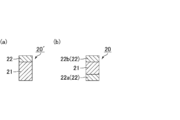
- FIG. 1 (a) is a perspective view schematically showing an example of the lithium ion battery separator of the present invention
- FIG. 1 (b) is a sectional view taken along the line AA in FIG. 1 (a).
- Fig.2 (a) and FIG.2 (b) are sectional drawings which each show typically the example of a structure of the frame-shaped member which comprises the separator for lithium ion batteries of this invention.
- FIGS. 3 (a) to 3 (e) are cross-sectional views showing an example of the positional relationship between the separator body constituting the lithium ion battery separator of the present invention and the layers constituting the frame-like member.
- FIG. 4 (a) to 4 (f) are explanatory views schematically showing an example of a method for producing a lithium ion battery using the lithium ion battery separator of the present invention.
- FIG. 5 is an explanatory view schematically showing an example of a lithium ion battery provided with the lithium ion battery separator of the present invention.
- FIG. 6 is an explanatory view schematically showing another example of a lithium ion battery provided with the lithium ion battery separator of the present invention.
- the lithium ion battery separator of the present invention is a lithium ion battery separator disposed between a flat positive electrode current collector and a flat negative electrode current collector. Furthermore, the separator of the present invention is composed of a sheet-like separator main body made of a polyolefin porous membrane, and a frame-like member arranged annularly along the outer periphery of the separator main body. Further, the frame-like member is composed of a heat-resistant annular support member, and a positive electrode current collector or a negative electrode current collector disposed on the surface of the heat-resistant annular support member and a seal layer which can be thermocompression-bonded. By having such a configuration, the lithium ion battery separator of the present invention can achieve both excellent handleability and suppression of thermal deformation without changing the thickness of the separator.
- the lithium ion battery separator of the present invention may be used for a wound type lithium ion battery (hereinafter, also simply referred to as a wound battery), or a laminated (non-wound) lithium ion battery (hereinafter simply referred to as They may also be used in stack type batteries).
- a wound type lithium ion battery hereinafter, also simply referred to as a wound battery
- a laminated (non-wound) lithium ion battery hereinafter simply referred to as They may also be used in stack type batteries.
- FIG. 1 (a) is a perspective view schematically showing an example of the lithium ion battery separator of the present invention
- FIG. 1 (b) is a sectional view taken along the line AA in FIG. 1 (a).
- the lithium ion battery separator 1 is composed of a flat separator body 10 and a frame-shaped member 20 disposed annularly along the outer periphery of the separator body 10. Further, as shown in FIGS. 1A and 1B, since the outer dimension of the frame-like member 20 is larger than the outer dimension of the separator main body 10, the side surface of the separator main body 10 is covered by the frame-like member 20. ing.
- FIG.2 (a) and FIG.2 (b) are sectional drawings which each show typically the example of a structure of the frame-shaped member which comprises the separator for lithium ion batteries of this invention.
- the frame-like members (20 ', 20) constituting the lithium ion battery separator are, as shown in FIGS. 2 (a) and 2 (b), a heat-resistant annular support member 21 and a positive electrode disposed on the surface thereof.
- FIG. 2 (a) and 2 (b) are sectional drawings which each show typically the example of a structure of the frame-shaped member which comprises the separator for lithium ion batteries of this invention.
- the frame-like members (20 ', 20) constituting the lithium ion battery separator are, as shown in FIGS. 2 (a) and 2 (b), a heat-resistant annular support member 21 and a positive electrode disposed on the surface thereof.
- the seal layer 22 constituting the frame member 20 is a first seal layer 22a that can be thermocompression-bonded to a positive electrode current collector, and a first seal layer 22a that can be thermocompression-bonded to a negative electrode current collector. You may be comprised from 2 seal
- the frame-like member 20 may be a laminate in which the heat-resistant annular support member 21 is disposed between the first seal layer 22a and the second seal layer 22b. In the frame-like members shown in FIGS. 2A and 2B, the description of the separator main body is omitted, but the position at which the separator main body is disposed is not particularly limited.
- the frame-like members arranged annularly along the outer periphery of the separator main body support the separator main body, so that the handling property is excellent as compared with the case of the separator main body alone. Furthermore, even when the separator body is exposed to conditions that cause thermal deformation, the thermal deformation of the separator body can be suppressed by the heat-resistant annular supporting member maintaining its shape.
- the frame-like member is disposed only at the outer peripheral portion of the separator main body, the thickness of the separator main body sandwiched between the positive electrode active material layer and the negative electrode active material layer is maintained thin and Does not increase the ion resistance of the Therefore, in the lithium ion battery separator of the present invention, it is possible to achieve both excellent handleability and suppression of thermal deformation without changing the thickness of the separator.
- the seal layer formed on the surface of the heat-resistant annular support member enables adhesion between the lithium ion battery separator of the present invention and the current collector. Therefore, when bonding the lithium ion battery separator and the current collector, it is not necessary to separately prepare an adhesive, and the manufacturing process can be simplified.
- the surface of the heat-resistant annular support member refers to the surface of the heat-resistant annular support member facing the current collector, but the seal layer is also formed on the other surface (for example, the outer surface or inner surface of the heat-resistant annular support member). It may be arranged. That is, the sealing layer may be disposed only on the surface of the heat-resistant annular support member facing the current collector, or may be disposed on the other surface.
- the heat-resistant annular support member preferably contains a heat-resistant resin composition having a melting temperature of 150 ° C. or more, and more preferably contains a heat-resistant resin composition having a melting temperature of 200 ° C. or more.
- the melting temperature (also simply referred to as the melting point) of the heat resistant resin composition is measured by differential scanning calorimetry according to JIS K 7 12 1-1987.
- thermosetting resin epoxy resin, polyimide and the like
- engineering resin polyamide (nylon 6 melting temperature: about 230 ° C., nylon 66] Melting temperature: about 270 ° C.
- polycarbonate also referred to as PC melting temperature: about 150 ° C.
- polyetheretherketone also referred to as PEEK: melting temperature: about 330 ° C.
- high melting point thermoplastic resin ⁇ polyethylene terephthalate (PET) Melt temperature: about 250 ° C.
- polyethylene naphthalate also referred to as PEN: melt temperature: about 260 ° C.
- high melting point polypropylene melt temperature: about 160 to 170 ° C.
- the high melting point thermoplastic resin refers to a thermoplastic resin having a melting temperature of 150 ° C. or higher, which is measured by differential scanning calorimetry according to J
- the heat resistant resin composition contains at least one resin selected from the group consisting of polyamide, polyethylene terephthalate, polyethylene naphthalate, high melting point polypropylene, polycarbonate and polyetheretherketone. Is desirable.
- the heat resistant resin composition may contain a filler.
- a melting temperature can be improved because a heat resistant resin composition contains a filler.
- the filler include inorganic fillers such as glass fibers and carbon fibers.
- the heat-resistant resin composition containing a filler include those obtained by impregnating glass fiber with an epoxy resin before curing and curing (also referred to as glass epoxy) and carbon fiber reinforced resin.
- the frame-like member constituting the lithium ion battery separator of the present invention is a laminate in which the heat-resistant annular support member is disposed between the first seal layer and the second seal layer, the laminate is still present It is only disposed along the outer peripheral portion of the separator body constituting the lithium ion battery separator of the invention. That is, the central part of the lithium ion battery separator of the present invention does not have a laminated structure as described in WO 2007/66768 (corresponding to US Patent Application Publication 2007/0264577). Therefore, the internal resistance of the battery can be reduced.
- the seal layer constituting the frame-like member may have a single-layer structure or a multi-layer structure. That is, the seal layer may be composed of the positive electrode current collector and the first seal layer capable of thermocompression bonding, and the negative electrode current collector and the second seal layer capable of thermocompression bonding.
- the material constituting the seal layer may be a thermocompression bond with the current collector, and desirably includes, for example, a polyolefin.
- a polyolefin examples include commercially available polyolefin-based hot melt adhesive resins [Admar (registered trademark) manufactured by Mitsui Chemicals, Inc. and Mersen (registered trademark) manufactured by Tosoh Corporation], low melting point polyethylene, etc. .
- Admar registered trademark
- Mersen registered trademark
- low melting point polyethylene etc.
- the materials constituting the first seal layer and the second seal layer may be the same or different.
- Low-melting-point polyethylene refers to polyethylene having a melting temperature of less than 150 ° C., which is measured by differential scanning calorimetry according to JIS K 7 12 1-1987. From the viewpoint of suppressing the temperature rise of the separator body at the time of thermocompression bonding, the melting temperature of the low melting point polyethylene used for the seal layer is preferably 100 ° C. or less.
- the low melting point polyethylene that can be used for the lithium ion battery separator of the present invention includes commercially available low density polyethylene resin, high density polyethylene resin, and the like.
- the thickness of the frame-like member is not particularly limited, but preferably 60 to 600 ⁇ m.
- the thickness of the seal layer is not particularly limited, but the total thickness is preferably 10 to 100 ⁇ m.
- the thickness of the sealing layer is 10 to 100 ⁇ m, the adhesion to the current collector is good, which is preferable.
- the thickness of the heat-resistant annular support member is not particularly limited, but is preferably 50 to 500 ⁇ m. When the thickness of the heat-resistant annular support member is 50 to 500 ⁇ m, it is difficult to thermally deform, which is preferable.
- the heat resistant annular support member may be composed of two or more layers, and when the heat resistant annular support member is composed of two or more layers, the separator main body is disposed between the heat resistant annular support members. It may be
- the method of bonding the separator body and the frame member is not particularly limited, but may be bonded by an adhesive, or may be thermocompression bonded to a positive electrode current collector or a negative electrode current collector. May be joined using a part of the seal layer which can be used.
- the adhesive include the above-mentioned commercially available polyolefin hot melt adhesive resins and low melting point polyethylene.
- the separator main body and the frame-like member can also be formed by directly producing the frame-like member on the separator main body by a method of applying and then cooling the raw material of the frame-like member on the separator main body. It can be joined.
- the thickness of the sheet-like separator body made of the polyolefin porous membrane is not particularly limited, but is preferably 10 to 1000 ⁇ m.
- a known lithium ion battery separator made of porous polyolefin [Hipore (registered trademark) manufactured by Asahi Kasei Corporation, Celgard (registered trademark) manufactured by Asahi Kasei Corporation, and Ube Industries, Ltd.] Eupore (registered trademark) and the like manufactured by Corporation can be used.
- the shape in plan view of the lithium ion battery separator of the present invention is not particularly limited, and examples thereof include polygons such as triangles, squares and pentagons, circles, and ovals.
- the shapes of the separator body and the frame member constituting the lithium ion battery separator of the present invention are the shapes of the current collectors (positive electrode current collector and negative electrode current collector) to be combined with the lithium ion battery separator of the present invention and the present invention It may be adjusted according to the shape of the battery case etc. which accommodates the lithium ion battery separator.
- the external dimensions of the separator main body in the top view are preferably larger than the internal dimensions of the frame-like member and less than or equal to the external dimensions of the frame-like member in view of the connection between the separator main body and the frame-like member.
- the external dimensions of the separator main body satisfying the above conditions include, for example, a dimension larger than the internal dimension of the frame-like member and smaller than the external dimension, and the same dimension as the external dimension of the frame-like member. Among these, a dimension larger than the inner dimension of the frame-like member and smaller than the outer dimension is more desirable.
- the separator body is larger than the inner dimension of the frame-like member and smaller than the outer dimension, the separator body and the frame-like member are joined in a sufficient area, so thermal stress during sealing The frame member does not peel off.
- the separator body if the outer dimension of the separator body is larger than the outer dimension of the frame-like member, the separator body protrudes outward from the frame-like member, and this becomes an unnecessary space when manufacturing a lithium ion battery. It may lead to a decrease in density.
- the separator body is exposed to the side surface of the lithium ion battery separator, so to prevent leakage of electrolyte from the separator body. , And may need additional measures.
- the positional relationship between the separator main body and the frame member is not particularly limited.
- the separator main body is on the surface of the first seal layer (opposite to the heat resistant annular support member). It may be arranged.
- the separator main body may be disposed between the first seal layer and the heat-resistant annular support member, and the middle of the heat-resistant annular support member (a first heat-resistant annular support member and a second heat-resistant annular support member
- the separator body may be disposed between
- the separator main body may be disposed between the heat resistant annular support member and the second seal layer, and may be disposed on the surface of the second seal layer (opposite to the heat resistant annular support member). .
- the separator main body is disposed on the surface of the first seal layer (opposite to the heat resistant annular support member) and the separator main body is disposed on the surface of the second seal layer (opposite to the heat resistant annular support member) In this case, all of the frame-like members are disposed only on one side of the separator body. In consideration of the handleability of the lithium ion battery separator, it is desirable that the separator main body be in direct contact with the heat-resistant annular support member. More preferably, the separator main body is disposed in the middle of the heat resistant annular support member (between the first heat resistant annular support member and the second heat resistant annular support member).
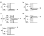
- FIG. 3A The positional relationship between the separator body and each layer (first seal layer, second seal layer, and heat-resistant annular support member) constituting the frame-like member in the lithium ion battery separator of the present invention is shown in FIG. An example is given and demonstrated using (e).
- 3 (a) to 3 (e) describe the case where the outer dimension of the separator body is larger than the inner dimension of the frame-like member and smaller than the outer dimension.
- FIGS. 3 (a) to 3 (e) are cross-sectional views showing an example of the positional relationship between the separator body constituting the lithium ion battery separator of the present invention and the layers constituting the frame-like member.
- the separator body 10 is disposed in contact with only the first seal layer 22a.
- FIG. 3A the separator body 10 is disposed in contact with only the first seal layer 22a.
- the separator body 10 is disposed between the first seal layer 22 a and the heat-resistant annular support member 21.
- the separator body 10 is disposed between the first heat-resistant annular support member 21a and the second heat-resistant annular support member 21b that constitute the heat-resistant annular support member 21.
- the separator body 10 is disposed between the heat-resistant annular support member 21 and the second seal layer 22b.
- the separator body 10 is disposed in contact with only the second seal layer 22b.
- the method for producing the lithium ion battery separator of the present invention is not particularly limited. For example, a method of separately preparing and combining a plate-like separator main body and a frame-like member, or a frame-like member on the surface of a plate-like separator main body And the like, and the like.
- the material used for each layer constituting the frame-like member is formed into a film and cut into a predetermined shape, if necessary There is a method of bonding to the outer periphery of the separator main body with an adhesive or the like.
- (3) a laminated body of each layer constituting the frame-like member is formed into a multilayer film, and then a method of adhering to a separator main body, etc. may be mentioned.
- the adhesive examples include the above-mentioned commercially available polyolefin hot melt adhesive resins and low melting point polyethylene.
- the method of forming the material constituting each layer into a film is not particularly limited, and examples thereof include an inflation method, a T-die method, a solution casting method, and a calendar method.
- the films obtained by these methods may be stretched or the like as needed. Stretching may be uniaxial stretching or biaxial stretching. Alternatively, a commercially available film may be cut into a predetermined shape and used.
- thermocompression-bonding devices a heating roll, a heat sealer (impulse sealer etc., etc.)
- a heat sealer impulse sealer etc., etc.
- the heat resistant annular support is applied by applying and drying a raw material solution to be a heat resistant annular support member on one surface of the separator body. Form a member.
- the first seal layer is formed by applying and drying a raw material solution to be the first seal layer on the surface of the heat-resistant annular support member.
- the separator main body is rotated, and the heat-resistant annular supporting member and the second seal layer are laminated on the surface on which the first seal layer is not formed in the same procedure as the first seal layer.
- the size and arrangement of the heat-resistant annular support member, the first seal layer, and the second seal layer can be appropriately adjusted according to the position of the frame member and the separator body in the lithium ion battery separator to be obtained.
- FIGS. 4 (a) to 4 (f) are explanatory views schematically showing an example of a method for producing a lithium ion battery using the lithium ion battery separator of the present invention.
- the raw material (positive electrode composition) 30a used as a positive electrode active material layer is first provided to one side of the separator 1 for lithium ion batteries.
- the positive electrode active material layer 30 is formed in the region surrounded by the separator body 10 and the frame-like member 20.
- the positive electrode current collector 40 is disposed so as to cover the positive electrode active material layer 30 and the frame-like member 20.
- the separator 1 for a lithium ion battery, the positive electrode active material layer 30, and the positive electrode current collector 40 are inverted to form the separator body 10 on the side on which the positive electrode active material layer 30 is not formed.
- a raw material (negative electrode composition) 31a to be a negative electrode active material layer is applied thereon.
- the negative electrode active material layer 31 is formed in the region surrounded by the separator body 10 and the frame-like member 20.
- the negative electrode current collector 41 is disposed so as to cover the negative electrode active material layer 31 and the frame-like member 20.
- the lithium ion battery 100 shown in FIG. 4 (f) is obtained.
- the lithium ion battery 100 shown in FIG. 4F is not housed in the battery outer package, but may be housed in the battery outer package as required. Further, when being accommodated in the battery case, a plurality of lithium ion batteries 100 may be stacked in series or in parallel.
- FIG. 5 is an explanatory view schematically showing an example of a lithium ion battery provided with the lithium ion battery separator of the present invention.
- the lithium ion battery 100 shown in FIG. 4 (f) is covered with a positive electrode exterior body 150 which is a battery exterior body and a negative electrode exterior body 151.
- the positive electrode case 150 and the negative electrode case 151 are electrically connected to the corresponding current collectors (the positive electrode current collector 40 and the negative electrode current collector 41).
- an insulating resin layer (not shown) is formed in a portion in contact with each other, and the positive electrode exterior body 150 and the negative electrode exterior body 151 are insulated.
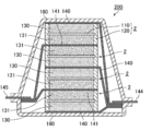
- FIG. 6 is an explanatory view schematically showing another example of a lithium ion battery provided with the lithium ion battery separator of the present invention.
- the lithium ion battery 200 shown in FIG. 6 has four lithium ion battery separators 2 in which the frame-like member 120 is disposed at the outer peripheral portion of the separator main body 110 in the battery outer package 160 having an insulating inner surface. It is stacked via the body 140 or the negative electrode current collector 141.
- the positive electrode active material layer 130 is formed between the separator body 110 and the positive electrode current collector 140.
- the negative electrode active material layer 131 is formed between the separator main body 110 and the negative electrode current collector 141.
- the lithium ion battery separator 2, the positive electrode structure adjacent to the separator 2, and the negative electrode structure adjacent to the separator 2 allow the battery unit to function as a lithium ion battery (similar to the lithium ion battery 100 shown in FIG. Structure).
- the positive electrode structure adjacent to the separator 2 has a positive electrode current collector 140 adjacent to the lithium ion battery separator 2 and a positive electrode active material layer 130 formed between the lithium ion battery separator 2 and the positive electrode current collector 140.
- the negative electrode structure adjacent to the separator 2 is a negative electrode current collector 141 adjacent to the lithium ion battery separator 2 and a negative electrode active material layer formed between the lithium ion battery separator 2 and the negative electrode current collector 141. It consists of 131.
- all the positive electrode current collectors 140 are connected to the external terminals 144 exposed to the outside of the battery outer package 160, and all the negative electrode current collectors 141 are connected to the external terminals 145 exposed to the outside of the battery outer package 160. It is done. Therefore, in the lithium ion battery 200, it can be said that four battery units are connected in parallel.
- the positive electrode composition, the negative electrode composition, the positive electrode current collector, and the negative electrode current collector used in the method for producing a lithium ion battery using the lithium ion battery separator of the present invention will be described.
- the positive electrode composition contains a positive electrode active material, and may contain a conductive auxiliary agent or an electrolytic solution as required.
- positive electrode active materials include complex oxides of lithium and transition metals, lithium-containing transition metal phosphates, transition metal oxides, transition metal sulfides, conductive polymers, etc. It is also good.
- composite oxides of lithium and transition metals include composite oxides in which one transition metal is used, composite oxides in which two transition metal elements are included, and composite oxides in which three or more types of metal elements are included.
- Be LiCoO 2 , LiNiO 2 , LiAlMnO 4 , LiMnO 2, LiMn 2 O 4 and the like can be mentioned as the composite oxide in which the transition metal is one kind.
- LiFeMnO 4 LiNi 1 -x Co x O 2 , LiMn 1 -y Co y O 2 , LiNi 1/3 Co 1/3 Al 1/3 O 2 and LiNi 0.8 Co 0.15 Al 0.05 O 2 and the like.
- LiNi 1/3 Mn 1/3 Co 1/3 O 2 ) and the like can be mentioned.
- lithium-containing transition metal phosphate for example, LiFePO 4, LiCoPO 4, LiMnPO 4 , and LiNiPO 4, and the like.
- transition metal oxides include MnO 2 and V 2 O 5 .
- transition metal sulfides include MoS 2 and TiS 2 .
- the conductive polymer include polyaniline, polyvinylidene fluoride, polypyrrole, polythiophene, polyacetylene, poly-p-phenylene and polycarbazole.
- the lithium-containing transition metal phosphate may have a part of the transition metal site substituted with another transition metal.
- the volume average particle size of the positive electrode active material for a lithium ion battery is preferably 0.01 to 100 ⁇ m, more preferably 0.1 to 35 ⁇ m, and more preferably 2 to 30 ⁇ m from the viewpoint of the electric characteristics of the battery. Is more preferred.
- the negative electrode composition contains a negative electrode active material, and may contain a conductive auxiliary agent or an electrolytic solution as needed.
- the negative electrode active material include carbon-based materials, silicon-based materials, conductive polymers, metals, metal oxides and metal alloys, and mixtures of these with carbon-based materials.
- carbon-based materials graphite, non-graphitizable carbon, amorphous carbon, resin fired bodies (eg, those obtained by calcinating and carbonizing phenol resin and furan resin etc.), cokes (eg, pitch coke, needle coke and petroleum coke) Etc.) and carbon fiber etc.
- Silicon-based materials include silicon, silicon oxide (SiOx), silicon-carbon composites (the surface of carbon particles coated with silicon and / or silicon carbide, and the surfaces of silicon particles or silicon oxide particles are carbon and / or carbonized Silicon-coated and silicon carbide etc. and silicon alloys (silicon-aluminium alloy, silicon-lithium alloy, silicon-nickel alloy, silicon-iron alloy, silicon-titanium alloy, silicon-manganese alloy, silicon-copper alloy and silicon) -Tin alloy etc. are mentioned.
- the conductive polymer include polyacetylene and polypyrrole.
- the metal include tin, aluminum, zirconium and titanium.
- metal oxides include titanium oxide and lithium-titanium oxide.
- metal alloys examples include lithium-tin alloys, lithium-aluminum alloys and lithium-aluminum-manganese alloys.
- lithium-tin alloys lithium-aluminum alloys
- lithium-aluminum-manganese alloys lithium-aluminum-manganese alloys.
- carbon materials silicon materials and mixtures thereof are preferable from the viewpoint of battery capacity etc.
- carbon materials graphite, non-graphitizable carbon and amorphous carbon are more preferable, and as the silicon materials More preferred are silicon oxide and silicon-carbon composites.
- the volume average particle diameter of the negative electrode active material is preferably 0.01 to 100 ⁇ m, more preferably 0.1 to 20 ⁇ m, and still more preferably 2 to 10 ⁇ m, from the viewpoint of the electrical characteristics of the battery.
- the volume average particle diameter of the positive electrode active material, the negative electrode active material, etc. means the particle diameter (Dv 50) at an integrated value of 50% in the particle size distribution determined by the microtrack method (laser diffraction / scattering method).
- the microtrack method is a method of obtaining a particle size distribution using scattered light obtained by irradiating particles with laser light.
- the microtrack etc. made by Nikkiso Co., Ltd. can be used for the measurement of a volume average particle diameter.
- the conductive aid is selected from materials having conductivity. Specific examples thereof include metals, carbon, and mixtures thereof, but not limited thereto. Examples of the metal include nickel, aluminum, stainless steel (SUS), silver, copper and titanium. Examples of carbon include graphite and carbon black (acetylene black, ketjen black (registered trademark), furnace black, channel black, thermal lamp black and the like) and the like. These conductive aids may be used alone or in combination of two or more. Alternatively, an alloy of these metals or a metal oxide may be used. From the viewpoint of electrical stability, it is preferably aluminum, stainless steel, carbon, silver, copper, titanium and a mixture thereof, more preferably silver, aluminum, stainless steel and carbon, and still more preferably carbon. In addition, as these conductive aids, conductive materials (metals of the above-mentioned conductive aids) may be plated around particle-based (particulate) ceramic materials or particle-based (particulate) resin materials. It may be coated.
- the average particle size of the conductive additive is not particularly limited, but is preferably 0.01 to 10 ⁇ m, more preferably 0.02 to 5 ⁇ m, from the viewpoint of the electrical characteristics of the battery. More preferably, it is in the range of 0.31 to 1 ⁇ m.
- the "particle diameter” means the largest distance L among the distance between any two points on the contour of the conductive additive.
- the value of “average particle diameter” is an average value of particle diameters of particles observed in several to several tens of visual fields using an observation means such as a scanning electron microscope (SEM) or a transmission electron microscope (TEM). The calculated value shall be adopted.
- the shape (form) of the conductive aid is not limited to the particle form, and may be a form other than the particle form, and may be a form such as a carbon nanotube that has been put to practical use as a so-called filler-based conductive resin composition Good.
- the conductive aid may be a conductive fiber whose shape is fibrous.
- conductive fibers include carbon fibers such as PAN-based carbon fibers and pitch-based carbon fibers, conductive fibers obtained by uniformly dispersing conductive metals and graphite in synthetic fibers, and metals such as stainless steel.
- covered the surface of the organic fiber with resin containing an electroconductive substance etc. are mentioned.
- carbon fibers are preferred.
- a polypropylene resin into which graphene is incorporated is also preferable.
- the average fiber diameter is preferably 0.1 to 20 ⁇ m.
- the positive electrode active material and the negative electrode active material may be a coated active material in which at least a part of the surface is coated with a coating layer containing a polymer compound.
- an electrode active material may be a coated active material in which at least a part of the surface is coated with a coating layer containing a polymer compound.
- the covering active material at the time of using a positive electrode active material as an electrode active material is called a covering positive electrode active material, and a covering active material layer is also called a covering positive electrode active material layer.
- a coated active material when a negative electrode active material is used as an electrode active material is referred to as a coated negative electrode active material, and a coated active material layer is also referred to as a coated negative electrode active material layer.
- electrolyte solution As electrolyte solution, the well-known electrolyte solution containing electrolyte and non-aqueous solvent used for manufacture of a lithium ion battery can be used.
- LiPF 6 LiBF 4, LiSbF 6, LiAsF 6 , and lithium salts of inorganic acids LiClO 4, etc., LiN (CF 3 SO 2) 2, LiN (C 2 F 5 SO 2) 2 and LiC (CF 3 SO 2 And 3 ) lithium salts of organic acids such as 3 ).
- LiPF 6 is preferable from the viewpoint of battery output and charge-discharge cycle characteristics.
- non-aqueous solvent those used in known electrolytic solutions can be used.
- lactone compounds, cyclic or chain carbonates, chain carboxylic acid esters, cyclic or chain ethers, phosphoric acid esters, nitrile compounds, amide compounds, sulfones, sulfolanes and the like and mixtures thereof can be used.
- lactone compounds examples include 5-membered ring lactone compounds (such as ⁇ -butyrolactone and ⁇ -valerolactone) and 6-membered ring lactone compounds (such as ⁇ -valerolactone).
- Examples of cyclic carbonates include propylene carbonate, ethylene carbonate and butylene carbonate.
- Examples of chain carbonates include dimethyl carbonate, methyl ethyl carbonate, diethyl carbonate, methyl-n-propyl carbonate, ethyl-n-propyl carbonate and di-n-propyl carbonate.
- chain carboxylic acid esters include methyl acetate, ethyl acetate, propyl acetate and methyl propionate.
- cyclic ethers include tetrahydrofuran, tetrahydropyran, 1,3-dioxolane and 1,4-dioxane.
- chain ether include dimethoxymethane and 1,2-dimethoxyethane.
- trimethyl phosphate triethyl phosphate, ethyl dimethyl phosphate, diethyl methyl phosphate, tripropyl phosphate, tributyl phosphate, tri (trifluoromethyl) phosphate, tri (trichloromethyl) phosphate, Tri (trifluoroethyl) phosphate, tri (triperfluoroethyl) phosphate, 2-ethoxy-1,3,2-dioxaphospholan-2-one, 2-trifluoroethoxy-1,3,2- Examples include dioxaphospholan-2-one and 2-methoxyethoxy-1,3,2-dioxaphospholane-2-one. Acetonitrile etc.
- nitrile compound examples include N, N-dimethylformamide (DMF) and the like.
- amide compound examples include N, N-dimethylformamide (DMF) and the like.
- sulfone examples include dimethylsulfone and diethylsulfone.
- a non-aqueous solvent may be used individually by 1 type, and may use 2 or more types together.
- lactone compounds Among non-aqueous solvents, lactone compounds, cyclic carbonates, chain carbonates and phosphates are preferable from the viewpoint of battery power and charge-discharge cycle characteristics. Further preferred are lactone compounds, cyclic carbonates and chain carbonates, and particularly preferred are mixed solutions of cyclic carbonates and chain carbonates. Most preferred is a mixture of ethylene carbonate (EC) and dimethyl carbonate (DMC), or a mixture of ethylene carbonate (EC) and diethyl carbonate (DEC).
- EC ethylene carbonate
- DMC dimethyl carbonate
- DEC diethyl carbonate
- metal current collectors such as copper, aluminum, titanium, metal foils such as stainless steel and nickel, and conductive polymers (described in JP 2012-150905 A, etc.) And conductive carbon sheets and conductive glass sheets.
- the coated active material may be produced, for example, by mixing a polymer compound and an electrode active material, and an optionally used conductive agent.
- a conductive agent is used for the coating layer
- the polymer compound and the conductive agent may be mixed to prepare a coating material, and then the coating material and the electrode active material may be mixed to produce the polymer compound.
- a mixture of a conductive agent and an electrode active material is not particularly limited, but after the electrode active material and the polymer compound are mixed, a conductive agent is further added and further mixed Is preferred.
- at least a part of the surface of the electrode active material is coated with the coating layer containing the polymer compound and the conductive agent optionally used.
- the same one as the conductive aid constituting the electrode composition can be suitably used.
- Example 1 [Production of frame-shaped member] An adhesive polyolefin resin film as a seal layer was laminated on both sides of the polyethylene naphthalate film as a heat resistant annular support member. The heat-resistant annular support member and the seal layer were adhered by a heating roll to prepare a laminate. Thereafter, the laminate was cut into a square of 15 mm ⁇ 15 mm, and a central 11 mm ⁇ 11 mm area was punched out. As a result, a heat-resistant annular support member (PEN layer) made of PEN and a seal layer were laminated, and an annular laminate (frame-like member) having a width of 2 mm on four sides of a square was obtained.
- PEN layer heat-resistant annular support member
- the polyethylene naphthalate film used was a PEN film manufactured by Teijin Limited, Theonex (registered trademark) Q51, having a thickness of 250 ⁇ m.
- Admer (registered trademark) VE300 manufactured by Mitsui Chemicals, Inc., having a thickness of 50 ⁇ m was used.
- the first seal layer is a seal layer on the opposite side to the second seal layer, and the first seal layer is in contact with the positive electrode current collector, and the second seal layer is in contact with the negative electrode current collector. Seal layer on the side.
- the second seal layer is disposed at a width of 0.5 mm from the outer periphery of the frame-like member, and the separator body is bonded by the second seal layer at a width of 1.5 mm outside the frame-like member. It is stacked.
- Example 1 since the frame-like member is formed on the outer peripheral portion of the separator main body, bending and wrinkles are not generated during handling, and the flat surface is maintained. (Excellent evaluation: ⁇ ).
- Example 2 to 4 In [Production of frame-shaped member], the heat-resistant annular support member was changed to a polyethylene naphthalate film, a polyetheretherketone film and a glass epoxy laminate, respectively.
- a lithium ion battery separator according to each of Examples 2 to 4 was obtained by the same procedure as Example 1 except for the above changes.
- the handling property was the same as that of the lithium ion battery separator according to Example 1 (handling evaluation:)).
- the polyethylene naphthalate film used was a PEN film manufactured by Teijin Limited, Teonex (registered trademark) Q51, and 125 ⁇ m thick.
- polyetheretherketone film a PEEK film manufactured by Shin-Etsu Polymer Co., Ltd., Sepla (Shin-Etsu Sepla Film (registered trademark)), having a thickness of 50 ⁇ m was used.
- Sepla Shin-Etsu Sepla Film (registered trademark)
- SUMILITE registered trademark
- SUMILITE manufactured by Sumitomo Bakelite Co., Ltd. having a thickness of 100 ⁇ m was used.
- Example 5 Two frame members obtained in Example 2 and a separator main body were used. In order that the center of gravity based on the outer dimensions of the frame-like member and the center of gravity based on the outer dimension of the separator body overlap, and one seal layer of the frame-like member contacts the separator body, Frame-like members were stacked on each. The frame-like member was heated by an impulse sealer and melt-bonded to the separator body to obtain a separator in which the frame-like members were disposed on the surfaces on both sides along the outer periphery of the separator body.
- the side in contact with the positive electrode current collector is referred to as the first seal layer
- the side in contact with the negative electrode current collector is referred to as the second seal layer.
- two frame-like members are opposed via the separator main body.
- the lithium ion battery separator according to Example 5 is excellent in the handling property because the frame-like member is formed on the outer peripheral part of the separator main body, so that no bending or wrinkles occur during the handling (the handling property is evaluated) : ⁇ ).
- Comparative example 1 The separator body obtained in Production Example 1 was used as it is as a lithium ion battery separator according to Comparative Example 1.
- the lithium ion battery separator according to Comparative Example 1 was easily bent when lifted, and its handleability was inferior to the lithium ion battery separators according to Examples 1 to 5 (Handability evaluation: x).
- an adhesive polyolefin resin having a frame shape (width 2 mm) in which a square area of 15 mm ⁇ 15 mm and an area of 11 mm ⁇ 11 mm at the center are punched on the both sides of the lithium ion battery separator according to Comparative Example 1.
- the film was laminated. Specifically, lamination was performed so that the center of gravity based on the outer dimension of the lithium ion battery separator and the center of gravity based on the outer dimension of the adhesive polyolefin resin film overlap each other. Further, the upper and lower surfaces thereof were sandwiched between a 50 ⁇ m thick copper foil and an 50 ⁇ m thick aluminum foil.
- the lithium ion battery using the lithium ion battery separator of the present invention is excellent in the handling property and the heat deformation resistance.
- the lithium ion battery separator of the present invention is particularly useful as a separator for bipolar secondary batteries and lithium ion secondary batteries used for mobile phones, personal computers, hybrid vehicles and electric vehicles.
Landscapes
- Chemical & Material Sciences (AREA)
- Chemical Kinetics & Catalysis (AREA)
- Electrochemistry (AREA)
- General Chemical & Material Sciences (AREA)
- Engineering & Computer Science (AREA)
- Manufacturing & Machinery (AREA)
- Materials Engineering (AREA)
- Composite Materials (AREA)
- Cell Separators (AREA)
- Secondary Cells (AREA)
Abstract
本発明は、セパレータの厚さを変えることなく、優れた取扱性と熱変形の抑制を両立させることができるリチウムイオン電池用セパレータを提供する。 本発明は、平板状の正極集電体と平板状の負極集電体との間に配置されるリチウムイオン電池用セパレータであって、ポリオレフィン多孔質膜からなるシート状のセパレータ本体と、上記セパレータ本体の外周に沿って環状に配置される枠状部材とからなり、上記枠状部材は、耐熱性環状支持部材と、上記耐熱性環状支持部材の表面に配置される、正極集電体又は負極集電体と熱圧着が可能なシール層とからなることを特徴とするリチウムイオン電池用セパレータである。
Description
本発明は、リチウムイオン電池用セパレータに関する。
近年、環境保護のため二酸化炭素排出量の低減が切に望まれている。自動車業界では、電気自動車(EV)やハイブリッド電気自動車(HEV)の導入による二酸化炭素排出量の低減に期待が集まっており、これらの実用化の鍵を握るモータ駆動用二次電池の開発が鋭意行われている。二次電池としては、高エネルギー密度、高出力密度が達成できるリチウムイオン電池(リチウムイオン二次電池ともいう)に注目が集まっている。
リチウムイオン電池を構成する材料のうち、正極と負極との短絡を防ぐ部材であるセパレータとしては、安全性の観点からポリオレフィンの多孔質膜を基材としたものが多く用いられている。ポリオレフィンの多孔質膜は、電池が短絡や過充電などによって急激に発熱した時に溶融して空孔を閉塞することで電池の内部抵抗を上昇させて電池の安全性を向上させる機能(シャットダウン機能)がある。
一方で、セパレータ基材であるポリオレフィンの多孔質膜は、延伸によって多孔質構造を形成しているため、所定の温度(収縮温度)以上に加熱されると収縮・変形(以下、熱変形ともいう)を起こす特性を有している。そのため、電池の使用による発熱や電池製造時に加えられる熱によってセパレータ基材の温度が上記収縮温度を超えて熱変形を起こしてしまい、内部短絡が発生する恐れがあった。
熱変形による内部短絡を防止できるセパレータとして、国際公開第2007/66768号(米国特許出願公開第2007/0264577号明細書に相当)に記載のセパレータが提案されている。詳しくは、融点80~130℃の樹脂A及び加熱により非水電解液を吸収して膨張する樹脂Bからなる第1セパレータ層と、耐熱温度が150℃以上のフィラーを主体として含む第2セパレータ層とからなり、第1セパレータ層又は第2セパレータ層の少なくとも一方が板状粒子を含むセパレータが開示されている。
リチウムイオン電池の電気容量の観点から、全体に占める電極活物質の比率は高い方が好ましい。また電極間のイオン抵抗を低下させる観点からセパレータはその厚さを薄くすることが望まれている。しかしながら、セパレータの厚さが薄くなるほど、その取扱性が低下し、積層時の位置合わせが困難になったり、シワが発生しやすくなるという問題があった。
一方、熱変形による内部短絡を防止することができる国際公開第2007/66768号(米国特許出願公開第2007/0264577号明細書に相当)に記載されたセパレータは、積層体であるためにセパレータの厚さが従来のものに比べて厚くなりやすい。そのため、セパレータの取扱性は向上するが、リチウムイオン電池全体に占めるセパレータの容積が増加する分だけ、リチウムイオン電池全体に占める電極活物質の比率が減少して容量を大きくすることが困難になるという問題があった。
本発明は、上記課題を鑑みてなされたものであり、セパレータの厚さを変えることなく、優れた取扱性と熱変形の抑制を両立させることができるリチウムイオン電池用セパレータを提供することを目的とする。
本発明者らは、上記課題を解決するために鋭意検討した結果、本発明に到達した。すなわち、本発明は、平板状の正極集電体と平板状の負極集電体との間に配置されるリチウムイオン電池用セパレータである。さらに、本発明のセパレータは、ポリオレフィン多孔質膜からなるシート状のセパレータ本体と、上記セパレータ本体の外周に沿って環状に配置される枠状部材とからなる。さらに上記枠状部材は、耐熱性環状支持部材と、上記耐熱性環状支持部材の表面に配置される、正極集電体又は負極集電体と熱圧着が可能なシール層と、からなることを特徴とするリチウムイオン電池用セパレータに関する。
以下、本発明を詳細に説明する。なお、本明細書において、リチウムイオン電池と記載する場合、リチウムイオン二次電池も含む概念とする。
本発明のリチウムイオン電池用セパレータは、平板状の正極集電体と平板状の負極集電体との間に配置されるリチウムイオン電池用セパレータである。さらに、本発明のセパレータは、ポリオレフィン多孔質膜からなるシート状のセパレータ本体と、上記セパレータ本体の外周に沿って環状に配置される枠状部材とからなる。さらに上記枠状部材は、耐熱性環状支持部材と、上記耐熱性環状支持部材の表面に配置される、正極集電体又は負極集電体と熱圧着が可能なシール層とからなる。かかる構成を有することにより、本発明のリチウムイオン電池用セパレータは、セパレータの厚さを変えることなく、優れた取扱性と熱変形の抑制を両立させることができる。
本発明のリチウムイオン電池用セパレータは、巻回型のリチウムイオン電池(以下、単に巻回型電池ともいう)に用いてもよく、積層型(非巻回式)のリチウムイオン電池(以下、単に積層型電池ともいう)に用いてもよい。積層型電池を製造する際に、特にセパレータの取り扱いに精密さが要求されることを考慮すると、積層型(非巻回式)リチウムイオン電池に用いることが望ましい。
本発明のリチウムイオン電池用セパレータの構成を、図1(a)及び図1(b)を用いて説明する。図1(a)は本発明のリチウムイオン電池用セパレータの一例を模式的に示す斜視図であり、図1(b)は、図1(a)におけるA-A線断面図である。図1(a)に示すように、リチウムイオン電池用セパレータ1は、平板状のセパレータ本体10と、セパレータ本体10の外周に沿って環状に配置される枠状部材20とからなる。また、図1(a)及び図1(b)に示すように、枠状部材20の外形寸法はセパレータ本体10の外形寸法よりも大きいため、セパレータ本体10の側面は枠状部材20により覆われている。
続いて、本発明のリチウムイオン電池用セパレータを構成する枠状部材の構成について、図2(a)及び図2(b)を用いて説明する。図2(a)及び図2(b)はそれぞれ、本発明のリチウムイオン電池用セパレータを構成する枠状部材の構成の例を模式的に示す断面図である。リチウムイオン電池用セパレータを構成する枠状部材(20’、20)は、図2(a)及び図2(b)に示すように、耐熱性環状支持部材21と、その表面に配置される正極集電体又は負極集電体と熱圧着が可能なシール層22で構成されている。図2(b)に示すように、枠状部材20を構成するシール層22は、正極集電体と熱圧着が可能な第1シール層22aと、負極集電体と熱圧着が可能な第2シール層22bから構成されていてもよい。また、枠状部材20が、第1シール層22aと第2シール層22bの間に耐熱性環状支持部材21が配置された積層体であってもよい。なお、図2(a)及び図2(b)に示す枠状部材では、セパレータ本体の記載を省略しているが、セパレータ本体が配置される位置は特に限定されない。
本発明のリチウムイオン電池用セパレータでは、セパレータ本体の外周に沿って環状に配置された枠状部材がセパレータ本体を支持しているため、セパレータ本体単独の場合と比較して取扱性に優れる。さらに、セパレータ本体が熱変形を起こすような条件に晒された場合であっても、耐熱性環状支持部材がその形状を保持することで、セパレータ本体の熱変形を抑制することができる。また、枠状部材が配置されているのはセパレータ本体の外周部のみであるため、正極活物質層及び負極活物質層の間に挟まれるセパレータ本体の厚さは薄いままで維持され、電極間のイオン抵抗を増加させるものではない。従って、本発明のリチウムイオン電池用セパレータでは、セパレータの厚さを変えることなく、優れた取扱性と熱変形の抑制とを両立させることができる。そして、耐熱性環状支持部材の表面に形成されたシール層が本発明のリチウムイオン電池用セパレータと集電体との接着を可能とする。そのため、リチウムイオン電池用セパレータと集電体とを接着する際に、別途接着剤を準備する必要がなく、製造工程を簡素化することができる。
耐熱性環状支持部材の表面とは、耐熱性環状支持部材の集電体と対向する面を指すが、それ以外の面(例えば耐熱性環状支持部材の外側面や内側面)にもシール層が配置されていてもよい。すなわち、シール層は、耐熱性環状支持部材のうち集電体と対向する面だけに配置されていてもよく、それ以外の面にも配置されていてもよい。
耐熱性環状支持部材は、溶融温度が150℃以上である耐熱性樹脂組成物を含んでいることが望ましく、溶融温度が200℃以上である耐熱性樹脂組成物を含んでいることがより望ましい。耐熱性環状支持部材が、溶融温度150℃以上である耐熱性樹脂組成物を含むことで、枠状部材が熱に対してより変形しにくくなる。耐熱性樹脂組成物の溶融温度(単に融点ともいう)は、JIS K7121-1987に準拠して示差走査熱量測定によって測定される。
本発明のリチウムイオン電池用セパレータにおいて、耐熱性樹脂組成物を構成する樹脂としては、熱硬化性樹脂(エポキシ樹脂及びポリイミド等)、エンジニアリング樹脂[ポリアミド(ナイロン6 溶融温度:約230℃、ナイロン66 溶融温度:約270℃等)、ポリカーボネート(PCともいう 溶融温度:約150℃)及びポリエーテルエーテルケトン(PEEKともいう 溶融温度:約330℃)等]及び高融点熱可塑性樹脂{ポリエチレンテレフタレート(PETともいう 溶融温度:約250℃)、ポリエチレンナフタレート(PENともいう 溶融温度:約260℃)及び高融点ポリプロピレン(溶融温度:約160~170℃)等}等が挙げられる。なお、高融点熱可塑性樹脂とは、JIS K7121-1987に準拠して示差走査熱量測定によって測定される溶融温度が150℃以上の熱可塑性樹脂を指す。
本発明のリチウムイオン電池用セパレータにおいて、耐熱性樹脂組成物は、ポリアミド、ポリエチレンテレフタレート、ポリエチレンナフタレート、高融点ポリプロピレン、ポリカーボネート及びポリエーテルエーテルケトンからなる群から選択される少なくとも1種の樹脂を含むことが望ましい。
本発明のリチウムイオン電池用セパレータにおいて、耐熱性樹脂組成物は、フィラーを含んでいてもよい。耐熱性樹脂組成物がフィラーを含むことで、溶融温度を向上させることができる。上記フィラーとしては、ガラス繊維等の無機フィラー及び炭素繊維等が挙げられる。フィラーを含む耐熱性樹脂組成物としては、ガラス繊維に硬化前のエポキシ樹脂を含浸させて硬化させたもの(ガラスエポキシともいう)及び炭素繊維強化樹脂などが挙げられる。
本発明のリチウムイオン電池用セパレータを構成する枠状部材が、第1シール層と第2シール層の間に耐熱性環状支持部材が配置された積層体であったとしても、該積層体は本発明のリチウムイオン電池用セパレータを構成するセパレータ本体の外周部に沿って配置されているに過ぎない。すなわち、本発明のリチウムイオン電池用セパレータの中央部は、国際公開第2007/66768号(米国特許出願公開第2007/0264577号明細書に相当)に記載されたような積層構造を有しない。従って、電池の内部抵抗を低下させることができる。
本発明のリチウムイオン電池用セパレータにおいて、枠状部材を構成するシール層は単層構造であってもよく、複層構造であってもよい。すなわち、シール層は、正極集電体と熱圧着が可能な第1シール層と、負極集電体と熱圧着が可能な第2シール層とからなっていてもよい。
シール層を構成する材料は、集電体と熱圧着が可能であればよく、例えばポリオレフィンを含むことが望ましい。シール層を構成するポリオレフィンとしては、例えば、市販のポリオレフィン系ホットメルト接着樹脂[三井化学株式会社製アドマー(登録商標)及び東ソー株式会社製メルセン(登録商標)等]及び低融点ポリエチレン等が挙げられる。またシール層が複層構造である場合、第1シール層と第2シール層を構成する材料は同じであってもよく、異なっていてもよい。なお、低融点ポリエチレンとは、JIS K7121-1987に準拠して示差走査熱量測定によって測定される溶融温度が150℃未満のポリエチレンを指す。熱圧着時におけるセパレータ本体の温度上昇を抑制する観点から、シール層に用いる低融点ポリエチレンの溶融温度は100℃以下が好ましい。なお、本発明のリチウムイオン電池用セパレータに用いることのできる低融点ポリエチレンには、市販の低密度ポリエチレン樹脂及び高密度ポリエチレン樹脂等が含まれる。
本発明のリチウムイオン電池用セパレータにおいて、枠状部材の厚さは、特に限定されないが、60~600μmであることが望ましい。
本発明のリチウムイオン電池用セパレータにおいて、シール層の厚さは、特に限定されないが、合計で10~100μmであることが望ましい。シール層の厚さが10~100μmであると、集電体との接着性が良好となり好ましい。
本発明のリチウムイオン電池用セパレータにおいて、耐熱性環状支持部材の厚さは、特に限定されないが、50~500μmであることが望ましい。耐熱性環状支持部材の厚さが50~500μmであると、熱変形しにくくなり好ましい。耐熱性環状支持部材は2層以上で構成されていてもよく、耐熱性環状支持部材が2層以上で構成されている場合には、耐熱性環状支持部材同士の間に、セパレータ本体が配置されていてもよい。
本発明のリチウムイオン電池用セパレータにおいて、セパレータ本体と枠状部材とを接合する方法は特に限定されないが、接着剤により接合されていてもよいし、正極集電体又は負極集電体と熱圧着が可能なシール層の一部を用いて接合されていてもよい。接着剤としては、上述した市販のポリオレフィン系ホットメルト接着樹脂及び低融点ポリエチレン等が挙げられる。また、枠状部材の原料を溶融させた状態でセパレータ本体上に塗布した後冷却する等の方法により、セパレータ本体上で直接枠状部材を作製することによっても、セパレータ本体と枠状部材とを接合させることができる。
本発明のリチウムイオン電池用セパレータにおいて、ポリオレフィン多孔質膜からなるシート状のセパレータ本体の厚さは、特に限定されないが、10~1000μmであることが望ましい。
本発明のリチウムイオン電池用セパレータにおいて、セパレータ本体としては、多孔質ポリオレフィンからなる公知のリチウムイオン電池用セパレータ[旭化成株式会社製ハイポア(登録商標)、旭化成株式会社製セルガード(登録商標)及び宇部興産株式会社製ユーポア(登録商標)等]を用いることができる。
本発明のリチウムイオン電池用セパレータの平面視形状は、特に限定されないが、三角形、四角形、五角形等の多角形や、円形、楕円形等が挙げられる。本発明のリチウムイオン電池用セパレータを構成するセパレータ本体及び枠状部材の形状は、本発明のリチウムイオン電池用セパレータと組み合わせる集電体(正極集電体及び負極集電体)の形状並びに本発明のリチウムイオン電池用セパレータを収容する電池外装体等の形状にあわせて調整すればよい。
上面視におけるセパレータ本体の外形寸法は、セパレータ本体と枠状部材との接続の関係から、枠状部材の内形寸法よりも大きく、枠状部材の外形寸法以下であることが望ましい。上記条件を満たすセパレータ本体の外形寸法は、例えば、枠状部材の内形寸法よりも大きく外形寸法よりも小さい寸法、枠状部材の外形寸法と同一の寸法が挙げられる。これらの中では、枠状部材の内形寸法よりも大きく外形寸法よりも小さい寸法がより望ましい。セパレータ本体の外形寸法が、枠状部材の内形寸法よりも大きく外形寸法よりも小さいと、セパレータ本体と枠状部材とが充分な面積で接合されるため、シール時の熱応力によってセパレータ本体から枠状部材が剥離することがない。一方、セパレータ本体の外形寸法が枠状部材の外形寸法よりも大きいと、枠状部材から外側に向かってセパレータ本体がはみ出すため、リチウムイオン電池を製造する際に不要な空間となってしまい、エネルギー密度の低下を招くことがある。また、セパレータ本体の外形寸法が枠状部材の外形寸法と同一であると、リチウムイオン電池用セパレータの側面にセパレータ本体が露出することとなるため、セパレータ本体からの電解液の漏れなどを防ぐために、別途対策が必要となることがある。
本発明のリチウムイオン電池用セパレータにおいて、セパレータ本体と枠状部材との位置関係は、特に限定されず、例えば、第1シール層の表面(耐熱性環状支持部材とは反対側)にセパレータ本体が配置されていてもよい。また、第1シール層と耐熱性環状支持部材との間にセパレータ本体が配置されていてもよく、耐熱性環状支持部材の中間(第1耐熱性環状支持部材と第2耐熱性環状支持部材との間)にセパレータ本体が配置されていてもよい。さらに、耐熱性環状支持部材と第2シール層との間にセパレータ本体が配置されていてもよく、第2シール層の表面(耐熱性環状支持部材とは反対側)に配置されていてもよい。第1シール層の表面(耐熱性環状支持部材とは反対側)にセパレータ本体が配置される場合及び第2シール層の表面(耐熱性環状支持部材とは反対側)にセパレータ本体が配置される場合、枠状部材の全部がセパレータ本体の片側だけに配置されることとなる。リチウムイオン電池用セパレータの取扱性を考慮すると、セパレータ本体が耐熱性環状支持部材と直接接触していることが望ましい。さらに、耐熱性環状支持部材の中間(第1耐熱性環状支持部材と第2耐熱性環状支持部材との間)にセパレータ本体が配置されていることがより望ましい。
本発明のリチウムイオン電池用セパレータにおけるセパレータ本体と枠状部材を構成する各層(第1シール層、第2シール層及び耐熱性環状支持部材)との位置関係について、図3(a)~図3(e)を用いて例を挙げて説明する。なお、図3(a)~図3(e)では、セパレータ本体の外形寸法が、枠状部材の内形寸法よりも大きく外形寸法よりも小さい場合について説明している。図3(a)~図3(e)は、本発明のリチウムイオン電池用セパレータを構成するセパレータ本体と枠状部材を構成する各層との位置関係の例を示す断面図である。図3(a)では、セパレータ本体10は、第1シール層22aのみと接するように配置されている。図3(b)では、セパレータ本体10は、第1シール層22aと耐熱性環状支持部材21との間に配置されている。図3(c)では、セパレータ本体10は、耐熱性環状支持部材21を構成する第1耐熱性環状支持部材21aと第2耐熱性環状支持部材21bとの間に配置されている。図3(d)では、セパレータ本体10は、耐熱性環状支持部材21と第2シール層22bとの間に配置されている。図3(e)では、セパレータ本体10は、第2シール層22bのみと接するように配置されている。
[リチウムイオン電池用セパレータを製造する方法]
本発明のリチウムイオン電池用セパレータを製造する方法は特に限定されないが、例えば、板状のセパレータ本体と枠状部材を別々に作製して組み合わせる方法や、板状のセパレータ本体の表面に枠状部材を構成する各層を順次積層する方法などが挙げられる。
本発明のリチウムイオン電池用セパレータを製造する方法は特に限定されないが、例えば、板状のセパレータ本体と枠状部材を別々に作製して組み合わせる方法や、板状のセパレータ本体の表面に枠状部材を構成する各層を順次積層する方法などが挙げられる。
セパレータ本体の外周に枠状部材を配置する方法としては、(1)枠状部材を構成する各層に用いる材料を、それぞれフィルム状に成形して、さらに所定の形状に切断した後、必要に応じて接着剤等によりセパレータ本体の外周にそれぞれ接着する方法が挙げられる。また、(2)枠状部材の各層を構成するフィルムを所定の形状に切断した後、加熱溶融してセパレータ本体の外周にそれぞれ接着する方法が挙げられる。さらに、(3)枠状部材を構成する各層の積層体を多層フィルムとした後、セパレータ本体に接着する方法等が挙げられる。接着剤としては、上述した市販のポリオレフィン系ホットメルト接着樹脂及び低融点ポリエチレン等が挙げられる。各層を構成する材料をフィルム状に成形する方法は、特に限定されないが、例えば、インフレーション法、T-ダイ法、溶液流延法、カレンダー法などが挙げられる。これらの方法で得られたフィルムは、必要に応じて延伸などを行ってもよい。延伸は、一軸延伸であってもよく、二軸延伸であってもよい。また、市販のフィルムを所定の形状に切断して用いてもよい。
枠状部材の各層を構成するフィルムを加熱溶融してセパレータ本体の外周に接着する場合、公知の熱圧着装置[加熱ロール及びヒートシーラー(インパルスシーラー等)等]を用いることができる。また、セパレータ本体の熱変形を抑える観点から、枠状部材を配置する部分のみを加熱して圧着することが好ましく、枠状部材となる部分だけをヒートシーラー(インパルスシーラー等)により加熱圧着することがより好ましい。
セパレータ本体上に直接枠状部材を構成する各層を順次積層する方法としては、例えば、セパレータ本体の一方の面に耐熱性環状支持部材となる原料溶液を塗布して乾燥することで耐熱性環状支持部材を形成する。さらに上記耐熱性環状支持部材の面上に第1シール層となる原料溶液を塗布して乾燥することで第1シール層を形成する。続いて、セパレータ本体を回転させて、第1シール層が形成されていない側の面に対して、第1シール層と同様の手順で、耐熱性環状支持部材及び第2シール層を積層する方法が挙げられる。耐熱性環状支持部材、第1シール層及び第2シール層の大きさ及び配置については、得たいリチウムイオン電池用セパレータにおける枠状部材とセパレータ本体との位置にあわせて適宜調整することができる。
[リチウムイオン電池の製造方法]
続いて、本発明のリチウムイオン電池用セパレータを用いてリチウムイオン電池を製造する方法について説明する。本発明のリチウムイオン電池用セパレータを用いてリチウムイオン電池を製造する方法は、例えば、図4(a)~図4(f)に示す工程により行われる。図4(a)~図4(f)は、本発明のリチウムイオン電池用セパレータを用いてリチウムイオン電池を製造する方法の一例を模式的に示す説明図である。図4(a)に示すように、まずリチウムイオン電池用セパレータ1の一方の面に正極活物質層となる原料(正極組成物)30aを付与する。この工程により、図4(b)に示すように、セパレータ本体10及び枠状部材20によって囲まれた領域内に正極活物質層30が形成される。続いて、図4(c)に示すように、正極活物質層30と枠状部材20とを覆うように、正極集電体40を配置する。その後、図4(d)に示すように、リチウムイオン電池用セパレータ1、正極活物質層30及び正極集電体40を反転させて、正極活物質層30が形成されていない側のセパレータ本体10上に負極活物質層となる原料(負極組成物)31aを付与する。この工程により、図4(e)に示すように、セパレータ本体10と枠状部材20によって囲まれた領域内に負極活物質層31が形成される。続いて、図4(f)に示すように、負極活物質層31と枠状部材20とを覆うように、負極集電体41を配置する。図4(a)~図4(e)に示す工程を経ることにより、図4(f)に示すリチウムイオン電池100が得られる。図4(f)に示すリチウムイオン電池100は、電池外装体に収容されていないが、必要に応じて電池外装体に収容してもよい。また、電池外装体に収容する際には、複数個のリチウムイオン電池100を直列又は並列に積層してもよい。
続いて、本発明のリチウムイオン電池用セパレータを用いてリチウムイオン電池を製造する方法について説明する。本発明のリチウムイオン電池用セパレータを用いてリチウムイオン電池を製造する方法は、例えば、図4(a)~図4(f)に示す工程により行われる。図4(a)~図4(f)は、本発明のリチウムイオン電池用セパレータを用いてリチウムイオン電池を製造する方法の一例を模式的に示す説明図である。図4(a)に示すように、まずリチウムイオン電池用セパレータ1の一方の面に正極活物質層となる原料(正極組成物)30aを付与する。この工程により、図4(b)に示すように、セパレータ本体10及び枠状部材20によって囲まれた領域内に正極活物質層30が形成される。続いて、図4(c)に示すように、正極活物質層30と枠状部材20とを覆うように、正極集電体40を配置する。その後、図4(d)に示すように、リチウムイオン電池用セパレータ1、正極活物質層30及び正極集電体40を反転させて、正極活物質層30が形成されていない側のセパレータ本体10上に負極活物質層となる原料(負極組成物)31aを付与する。この工程により、図4(e)に示すように、セパレータ本体10と枠状部材20によって囲まれた領域内に負極活物質層31が形成される。続いて、図4(f)に示すように、負極活物質層31と枠状部材20とを覆うように、負極集電体41を配置する。図4(a)~図4(e)に示す工程を経ることにより、図4(f)に示すリチウムイオン電池100が得られる。図4(f)に示すリチウムイオン電池100は、電池外装体に収容されていないが、必要に応じて電池外装体に収容してもよい。また、電池外装体に収容する際には、複数個のリチウムイオン電池100を直列又は並列に積層してもよい。
図4(f)に示すリチウムイオン電池100を電池外装体に収容した例を、図5を用いて説明する。図5は、本発明のリチウムイオン電池用セパレータを備えたリチウムイオン電池の一例を模式的に示す説明図である。図5に示すリチウムイオン電池100’では、図4(f)に示すリチウムイオン電池100が、電池外装体である正極外装体150及び負極外装体151により覆われている。正極外装体150及び負極外装体151は、対応する集電体(正極集電体40及び負極集電体41)とそれぞれ電気的に接続されている。一方で、互いの電池外装体と接触する部分には絶縁性の樹脂層(図示しない)が形成されており、正極外装体150と負極外装体151とは絶縁されている。
図4(f)に示すリチウムイオン電池100を電池単位として、これを複数個並列に接続したリチウムイオン電池の例について、図6を用いて説明する。図6は、本発明のリチウムイオン電池用セパレータを備えたリチウムイオン電池の別の一例を模式的に示す説明図である。図6に示すリチウムイオン電池200は、内面が絶縁性の電池外装体160内に、セパレータ本体110の外周部に枠状部材120が配置されたリチウムイオン電池用セパレータ2が4つ、正極集電体140又は負極集電体141を介して積層されている。セパレータ本体110と正極集電体140との間には、正極活物質層130が形成されている。また、セパレータ本体110と負極集電体141との間には、負極活物質層131が形成されている。リチウムイオン電池用セパレータ2、該セパレータ2に隣接する正極構造、及び該セパレータ2に隣接する負極構造により、リチウムイオン電池として機能する電池単位(図4(f)に示すリチウムイオン電池100と同様の構造)を構成している。前記セパレータ2に隣接する正極構造は、リチウムイオン電池用セパレータ2に隣接する正極集電体140及びリチウムイオン電池用セパレータ2と正極集電体140との間に形成されている正極活物質層130から構成されている。また前記セパレータ2に隣接する負極構造は、リチウムイオン電池用セパレータ2に隣接する負極集電体141及びリチウムイオン電池用セパレータ2と負極集電体141との間に形成されている負極活物質層131から構成されている。リチウムイオン電池200において、全ての正極集電体140は電池外装体160外に露出する外部端子144と接続され、全ての負極集電体141は電池外装体160外に露出する外部端子145と接続されている。従って、リチウムイオン電池200では、4つの電池単位が並列に接続されているといえる。
本発明のリチウムイオン電池用セパレータを用いてリチウムイオン電池を製造する方法に用いる、正極組成物、負極組成物、正極集電体及び負極集電体について説明する。
正極組成物は正極活物質を含んでなり、必要に応じて、導電助剤や電解液を含んでいてもよい。正極活物質としては、リチウムと遷移金属との複合酸化物、リチウム含有遷移金属リン酸塩、遷移金属酸化物、遷移金属硫化物及び導電性高分子等が挙げられ、2種以上を併用してもよい。リチウムと遷移金属との複合酸化物としては、遷移金属が1種である複合酸化物、遷移金属元素が2種である複合酸化物、及び金属元素が3種類以上である複合酸化物等が挙げられる。遷移金属が1種である複合酸化物としては、LiCoO2、LiNiO2、LiAlMnO4、LiMnO2及びLiMn2O4等が挙げられる。遷移金属元素が2種である複合酸化物としては、例えば、LiFeMnO4、LiNi1-xCoxO2、LiMn1-yCoyO2、LiNi1/3Co1/3Al1/3O2及びLiNi0.8Co0.15Al0.05O2等が挙げられる。金属元素が3種類以上である複合酸化物としては、例えば、LiMaM’bM’’cO2(M、M’及びM’’はそれぞれ異なる遷移金属元素であり、a+b+c=1を満たす。例えば、LiNi1/3Mn1/3Co1/3O2)等が挙げられる。また、リチウム含有遷移金属リン酸塩としては、例えば、LiFePO4、LiCoPO4、LiMnPO4及びLiNiPO4等が挙げられる。遷移金属酸化物としては、例えば、MnO2及びV2O5等が挙げられる。遷移金属硫化物としては、例えば、MoS2及びTiS2等が挙げられる。導電性高分子としては、例えば、ポリアニリン、ポリフッ化ビニリデン、ポリピロール、ポリチオフェン、ポリアセチレン及びポリ-p-フェニレン及びポリカルバゾール等が挙げられる。なお、リチウム含有遷移金属リン酸塩は、遷移金属サイトの一部を他の遷移金属で置換したものであってもよい。
リチウムイオン電池用正極活物質の体積平均粒子径は、電池の電気特性の観点から、0.01~100μmであることが好ましく、0.1~35μmであることがより好ましく、2~30μmであることがさらに好ましい。
負極組成物は負極活物質を含んでなり、必要に応じて、導電助剤や電解液を含んでいてもよい。負極活物質としては、炭素系材料、珪素系材料、導電性高分子、金属、金属酸化物及び金属合金等及びこれらと炭素系材料との混合物等が挙げられる。炭素系材料としては、黒鉛、難黒鉛化性炭素、アモルファス炭素、樹脂焼成体(例えばフェノール樹脂及びフラン樹脂等を焼成し炭素化したもの等)、コークス類(例えばピッチコークス、ニードルコークス及び石油コークス等)及び炭素繊維等が挙げられる。珪素系材料としては、珪素、酸化珪素(SiOx)、珪素-炭素複合体(炭素粒子の表面を珪素及び/又は炭化珪素で被覆したもの、珪素粒子又は酸化珪素粒子の表面を炭素及び/又は炭化珪素で被覆したもの並びに炭化珪素等)及び珪素合金(珪素-アルミニウム合金、珪素-リチウム合金、珪素-ニッケル合金、珪素-鉄合金、珪素-チタン合金、珪素-マンガン合金、珪素-銅合金及び珪素-スズ合金等)等が挙げられる。導電性高分子としては、例えば、ポリアセチレン及びポリピロール等が挙げられる。金属としては、スズ、アルミニウム、ジルコニウム及びチタン等が挙げられる。金属酸化物としては、チタン酸化物及びリチウム・チタン酸化物等が挙げられる。金属合金としては、例えば、リチウム-スズ合金、リチウム-アルミニウム合金及びリチウム-アルミニウム-マンガン合金等が挙げられる。上記負極活物質のうち、内部にリチウム又はリチウムイオンを含まないものについては、予め負極活物質の一部又は全部にリチウム又はリチウムイオンを含ませるプレドープ処理を施してもよい。
これらの中でも、電池容量等の観点から、炭素系材料、珪素系材料及びこれらの混合物が好ましく、炭素系材料としては、黒鉛、難黒鉛化性炭素及びアモルファス炭素がさらに好ましく、珪素系材料としては、酸化珪素及び珪素-炭素複合体がさらに好ましい。
負極活物質の体積平均粒子径は、電池の電気特性の観点から、0.01~100μmが好ましく、0.1~20μmであることがより好ましく、2~10μmであることがさらに好ましい。
本明細書において、正極活物質及び負極活物質等の体積平均粒子径は、マイクロトラック法(レーザー回折・散乱法)によって求めた粒度分布における積算値50%での粒径(Dv50)を意味する。マイクロトラック法とは、レーザー光を粒子に照射することによって得られる散乱光を利用して粒度分布を求める方法である。なお、体積平均粒子径の測定には、日機装株式会社製のマイクロトラック等を用いることができる。
導電助剤は、導電性を有する材料から選択される。具体的には、金属、カーボン、及びこれらの混合物等が挙げられるが、これらに限定されるわけではない。金属としては、ニッケル、アルミニウム、ステンレス(SUS)、銀、銅及びチタン等が挙げられる。カーボンとしては、グラファイト及びカーボンブラック(アセチレンブラック、ケッチェンブラック(登録商標)、ファーネスブラック、チャンネルブラック、サーマルランプブラック等)等が挙げられる。これらの導電助剤は1種単独で用いてもよいし、2種以上併用してもよい。また、これら金属の合金又は金属酸化物を用いてもよい。電気的安定性の観点から、好ましくはアルミニウム、ステンレス、カーボン、銀、銅、チタン及びこれらの混合物であり、より好ましくは銀、アルミニウム、ステンレス及びカーボンであり、さらに好ましくはカーボンである。またこれらの導電助剤としては、粒子系(粒子状)セラミック材料や粒子系(粒子状)樹脂材料の周りに導電性材料(上記した導電助剤の材料のうち金属のもの)をめっき等でコーティングしたものでもよい。
導電助剤の平均粒子径は、特に限定されるものではないが、電池の電気特性の観点から、0.01~10μmであることが好ましく、0.02~5μmであることがより好ましく、0.03~1μmであることがさらに好ましい。なお、本明細書中において、「粒子径」とは、導電助剤の輪郭線上の任意の2点間の距離のうち、最大の距離Lを意味する。「平均粒子径」の値としては、走査型電子顕微鏡(SEM)や透過型電子顕微鏡(TEM)等の観察手段を用い、数~数十視野中に観察される粒子の粒子径の平均値として算出される値を採用するものとする。
導電助剤の形状(形態)は、粒子形態に限られず、粒子形態以外の形態であってもよく、カーボンナノチューブ等、いわゆるフィラー系導電性樹脂組成物として実用化されている形態であってもよい。
導電助剤は、その形状が繊維状である導電性繊維であってもよい。導電性繊維としては、PAN系炭素繊維、ピッチ系炭素繊維等の炭素繊維、合成繊維の中に導電性のよい金属や黒鉛を均一に分散させてなる導電性繊維、ステンレス鋼のような金属を繊維化した金属繊維、有機物繊維の表面を金属で被覆した導電性繊維、有機物繊維の表面を導電性物質を含む樹脂で被覆した導電性繊維等が挙げられる。これらの導電性繊維の中では炭素繊維が好ましい。また、グラフェンを練りこんだポリプロピレン樹脂も好ましい。導電助剤が導電性繊維である場合、その平均繊維径は0.1~20μmであることが好ましい。
正極活物質及び負極活物質(以下、まとめて電極活物質ともいう)は、その表面の少なくとも一部が高分子化合物を含む被覆層により被覆された被覆活物質であってもよい。電極活物質の周囲が被覆層で被覆されていると、電極の体積変化が緩和され、電極の膨張を抑制することができる。さらに、被覆活物質の非水溶媒に対する濡れ性を向上させることができ、電極が有する被覆活物質層に電解液を吸収させる工程に掛かる時間の短縮が可能になる。なお、電極活物質として正極活物質を使用した場合の被覆活物質を被覆正極活物質といい、被覆活物質層を被覆正極活物質層ともいう。また電極活物質として負極活物質を使用した場合の被覆活物質を被覆負極活物質といい、被覆活物質層を被覆負極活物質層ともいう。
被覆層を構成する高分子化合物としては、特開2017-054703号公報に非水系二次電池活物質被覆用樹脂として記載されたものを好適に用いることができる。
(電解液)
電解液としては、リチウムイオン電池の製造に用いられる、電解質及び非水溶媒を含有する公知の電解液を使用することができる。
電解液としては、リチウムイオン電池の製造に用いられる、電解質及び非水溶媒を含有する公知の電解液を使用することができる。
電解質としては、公知の電解液に用いられているもの等が使用できる。例えば、LiPF6、LiBF4、LiSbF6、LiAsF6及びLiClO4等の無機酸のリチウム塩、LiN(CF3SO2)2、LiN(C2F5SO2)2及びLiC(CF3SO2)3等の有機酸のリチウム塩等が挙げられる。これらの内、電池出力及び充放電サイクル特性の観点から好ましいのはLiPF6である。
非水溶媒としては、公知の電解液に用いられているもの等が使用できる。例えば、ラクトン化合物、環状又は鎖状炭酸エステル、鎖状カルボン酸エステル、環状又は鎖状エーテル、リン酸エステル、ニトリル化合物、アミド化合物、スルホン、スルホラン等及びこれらの混合物を用いることができる。
ラクトン化合物としては、5員環のラクトン化合物(γ-ブチロラクトン及びγ-バレロラクトン等)及び6員環のラクトン化合物(δ-バレロラクトン等)等を挙げることができる。
環状炭酸エステルとしては、プロピレンカーボネート、エチレンカーボネート及びブチレンカーボネート等が挙げられる。鎖状炭酸エステルとしては、ジメチルカーボネート、メチルエチルカーボネート、ジエチルカーボネート、メチル-n-プロピルカーボネート、エチル-n-プロピルカーボネート及びジ-n-プロピルカーボネート等が挙げられる。
鎖状カルボン酸エステルとしては、酢酸メチル、酢酸エチル、酢酸プロピル及びプロピオン酸メチル等が挙げられる。環状エーテルとしては、テトラヒドロフラン、テトラヒドロピラン、1,3-ジオキソラン及び1,4-ジオキサン等が挙げられる。鎖状エーテルとしては、ジメトキシメタン及び1,2-ジメトキシエタン等が挙げられる。
リン酸エステルとしては、リン酸トリメチル、リン酸トリエチル、リン酸エチルジメチル、リン酸ジエチルメチル、リン酸トリプロピル、リン酸トリブチル、リン酸トリ(トリフルオロメチル)、リン酸トリ(トリクロロメチル)、リン酸トリ(トリフルオロエチル)、リン酸トリ(トリパーフルオロエチル)、2-エトキシ-1,3,2-ジオキサホスホラン-2-オン、2-トリフルオロエトキシ-1,3,2-ジオキサホスホラン-2-オン及び2-メトキシエトキシ-1,3,2-ジオキサホスホラン-2-オン等が挙げられる。ニトリル化合物としては、アセトニトリル等が挙げられる。アミド化合物としては、N,N-ジメチルホルムアミド(DMF)等が挙げられる。スルホンとしては、ジメチルスルホン及びジエチルスルホン等が挙げられる。非水溶媒は1種を単独で用いてもよいし、2種以上を併用してもよい。
非水溶媒の内、電池出力及び充放電サイクル特性の観点から好ましいのは、ラクトン化合物、環状炭酸エステル、鎖状炭酸エステル及びリン酸エステルである。更に好ましいのはラクトン化合物、環状炭酸エステル及び鎖状炭酸エステルであり、特に好ましいのは環状炭酸エステルと鎖状炭酸エステルの混合液である。最も好ましいのはエチレンカーボネート(EC)とジメチルカーボネート(DMC)の混合液、又は、エチレンカーボネート(EC)とジエチルカーボネート(DEC)の混合液である。
正極集電体及び負極集電体としては、銅、アルミニウム、チタン、ステンレス鋼及びニッケル等の金属箔、導電性高分子からなる樹脂集電体(特開2012-150905号公報等に記載されている)、導電性炭素シート及び導電性ガラスシート等が挙げられる。
上述した被覆活物質を製造する方法について説明する。被覆活物質は、例えば、高分子化合物及び電極活物質並びに必要により用いる導電剤を混合することによって製造してもよい。被覆層に導電剤を用いる場合には高分子化合物と導電剤とを混合して被覆材を準備したのち、該被覆材と電極活物質とを混合することにより製造してもよく、高分子化合物、導電剤及び電極活物質を混合することによって製造してもよい。なお、電極活物質と高分子化合物と導電剤とを混合する場合、混合順序には特に制限はないが、電極活物質と高分子化合物とを混合した後、更に導電剤を加えて更に混合することが好ましい。上記方法により、高分子化合物と必要により用いる導電剤を含む被覆層によって電極活物質の表面の少なくとも一部が被覆される。
被覆材の任意成分である導電剤としては、電極組成物を構成する導電助剤と同様のものを好適に用いることができる。
次に本発明を実施例によって具体的に説明するが、本発明の主旨を逸脱しない限り本発明の技術的範囲は実施例に限定されるものではない。なお、特記しない限り部は重量部、%は質量%を意味する。
[製造例1:セパレータ本体の製造]
平板状のセルガード2500(ポリプロピレン(PP)製、厚さ25μm)を14mm×14mmの正方形に切り出して、セパレータ本体とした。
平板状のセルガード2500(ポリプロピレン(PP)製、厚さ25μm)を14mm×14mmの正方形に切り出して、セパレータ本体とした。
(実施例1)
[枠状部材の作製]
耐熱性環状支持部材となるポリエチレンナフタレートフィルムの両面にシール層となる接着性ポリオレフィン系樹脂フィルムを重ねた。加熱ロールにより耐熱性環状支持部材とシール層とを接着して積層体を準備した。その後、積層体を15mm×15mmの正方形に切断し、さらに、中央の11mm×11mmの領域を打ち抜いた。このことにより、PENからなる耐熱性環状支持部材(PEN層)とシール層とが積層され、正方形の4辺における幅が2mmとなった環状の積層体(枠状部材)を得た。なお、ポリエチレンナフタレートフィルムには、帝人株式会社製PENフィルム、テオネックス(登録商標)Q51、厚さ250μmのものを用いた。接着性ポリオレフィン系樹脂フィルムには、三井化学株式会社製、アドマー(登録商標)VE300、厚さ50μmのものを用いた。
[セパレータ本体と枠状部材との接合]
枠状部材の外形寸法に基づく重心とセパレータ本体の外形寸法に基づく重心が重なるように、かつ、各枠状部材の一方のシール層(第2シール層とする)がセパレータ本体と接触するように、セパレータ本体の一方の面に枠状部材を重ねた。枠状部材をインパルスシーラーで加熱することによりセパレータ本体に溶融接着して、セパレータ本体の外周に沿って片側の面に枠状部材が環状に配置された実施例1に係るリチウムイオン電池用セパレータを得た。なお、第1シール層は第2シール層と反対面にあるシール層であり、第1シール層は正極集電体と接触する側のシール層、第2シール層は負極集電体と接触する側のシール層とした。なお、枠状部材の外周から内側に幅0.5mmの部分に第2シール層が配置されており、枠状部材から外側の幅1.5mmの部分では第2シール層によってセパレータ本体が接着、積層されている。実施例1に係るリチウムイオン電池用セパレータは、セパレータ本体の外周部に枠状部材が形成されているため、取扱時に折れ曲がりやシワが発生することがなく、平面を維持したままであり、取扱性に優れていた(取扱性評価:○)。
枠状部材の外形寸法に基づく重心とセパレータ本体の外形寸法に基づく重心が重なるように、かつ、各枠状部材の一方のシール層(第2シール層とする)がセパレータ本体と接触するように、セパレータ本体の一方の面に枠状部材を重ねた。枠状部材をインパルスシーラーで加熱することによりセパレータ本体に溶融接着して、セパレータ本体の外周に沿って片側の面に枠状部材が環状に配置された実施例1に係るリチウムイオン電池用セパレータを得た。なお、第1シール層は第2シール層と反対面にあるシール層であり、第1シール層は正極集電体と接触する側のシール層、第2シール層は負極集電体と接触する側のシール層とした。なお、枠状部材の外周から内側に幅0.5mmの部分に第2シール層が配置されており、枠状部材から外側の幅1.5mmの部分では第2シール層によってセパレータ本体が接着、積層されている。実施例1に係るリチウムイオン電池用セパレータは、セパレータ本体の外周部に枠状部材が形成されているため、取扱時に折れ曲がりやシワが発生することがなく、平面を維持したままであり、取扱性に優れていた(取扱性評価:○)。
(実施例2~4)
[枠状部材の作製]において、耐熱性環状支持部材を、ポリエチレンナフタレートフィルム、ポリエーテルエーテルケトンフィルム及びガラスエポキシ積層板にそれぞれ変更した。これらを変更したほかは、実施例1と同様の手順により、実施例2~4に係るリチウムイオン電池用セパレータを得た。取扱性に関しては、実施例1に係るリチウムイオン電池用セパレータと同様であった(取扱性評価:○)。なお、ポリエチレンナフタレートフィルムには、帝人株式会社製 PENフィルム、テオネックス(登録商標)Q51、厚さ125μmのものを用いた。ポリエーテルエーテルケトンフィルムには、信越ポリマー株式会社製 PEEKフィルム、Sepla(Shin-Etsu Sepla Film(登録商標))、厚さ50μmのものを用いた。ガラスエポキシ積層板には、住友ベークライト株式会社製 スミライト(登録商標)EL、厚さ100μmのものを用いた。
[枠状部材の作製]において、耐熱性環状支持部材を、ポリエチレンナフタレートフィルム、ポリエーテルエーテルケトンフィルム及びガラスエポキシ積層板にそれぞれ変更した。これらを変更したほかは、実施例1と同様の手順により、実施例2~4に係るリチウムイオン電池用セパレータを得た。取扱性に関しては、実施例1に係るリチウムイオン電池用セパレータと同様であった(取扱性評価:○)。なお、ポリエチレンナフタレートフィルムには、帝人株式会社製 PENフィルム、テオネックス(登録商標)Q51、厚さ125μmのものを用いた。ポリエーテルエーテルケトンフィルムには、信越ポリマー株式会社製 PEEKフィルム、Sepla(Shin-Etsu Sepla Film(登録商標))、厚さ50μmのものを用いた。ガラスエポキシ積層板には、住友ベークライト株式会社製 スミライト(登録商標)EL、厚さ100μmのものを用いた。
(実施例5)
実施例2で得られた枠状部材2つとセパレータ本体とを用いた。枠状部材の外形寸法に基づく重心とセパレータ本体の外形寸法に基づく重心とが重なるように、かつ、枠状部材の一方のシール層がセパレータ本体と接触するように、セパレータ本体の両側の面にそれぞれに枠状部材を重ねた。枠状部材をインパルスシーラーにより加熱してセパレータ本体に溶融接着して、セパレータ本体の外周に沿って両側の面に枠状部材が配置されたセパレータを得た。なお、セパレータ本体の両面に配置された枠状部材が有するシール層のうち、正極集電体と接触する側を第1シール層とし、負極集電体と接触する側を第2シール層とする。枠状部材の外周から内側0.5mmの部分においては、2つの枠状部材がセパレータ本体を介して対向している。実施例5に係るリチウムイオン電池用セパレータは、セパレータ本体の外周部に枠状部材が形成されているため、取扱時に折れ曲がりやシワが発生することがなく、取扱性に優れていた(取扱性評価:○)。
実施例2で得られた枠状部材2つとセパレータ本体とを用いた。枠状部材の外形寸法に基づく重心とセパレータ本体の外形寸法に基づく重心とが重なるように、かつ、枠状部材の一方のシール層がセパレータ本体と接触するように、セパレータ本体の両側の面にそれぞれに枠状部材を重ねた。枠状部材をインパルスシーラーにより加熱してセパレータ本体に溶融接着して、セパレータ本体の外周に沿って両側の面に枠状部材が配置されたセパレータを得た。なお、セパレータ本体の両面に配置された枠状部材が有するシール層のうち、正極集電体と接触する側を第1シール層とし、負極集電体と接触する側を第2シール層とする。枠状部材の外周から内側0.5mmの部分においては、2つの枠状部材がセパレータ本体を介して対向している。実施例5に係るリチウムイオン電池用セパレータは、セパレータ本体の外周部に枠状部材が形成されているため、取扱時に折れ曲がりやシワが発生することがなく、取扱性に優れていた(取扱性評価:○)。
(比較例1)
製造例1で得られたセパレータ本体をそのまま比較例1に係るリチウムイオン電池用セパレータとした。比較例1に係るリチウムイオン電池用セパレータは、持ち上げると容易に折れ曲がり、その取扱性は、実施例1~5に係るリチウムイオン電池用セパレータより劣るものであった(取扱性評価:×)。
製造例1で得られたセパレータ本体をそのまま比較例1に係るリチウムイオン電池用セパレータとした。比較例1に係るリチウムイオン電池用セパレータは、持ち上げると容易に折れ曲がり、その取扱性は、実施例1~5に係るリチウムイオン電池用セパレータより劣るものであった(取扱性評価:×)。
[セパレータの耐熱変形性の測定]
実施例1~5に係るリチウムイオン電池用セパレータを、厚さ50μmの銅箔と厚さ50μmのアルミニウム箔との間に挟んだ。200℃にセットしたインパルスシーラーを用いて、銅箔及びアルミニウム箔の上から枠状部材が存在している領域を1辺ずつ2秒間加熱し、金属箔と枠状部材とを加熱圧着して活物質層を含んでいない疑似単電池を作製した。また、比較例1に係るリチウムイオン電池用セパレータの両側の面に、外形寸法が15mm×15mmの正方形で中央の11mm×11mmの領域が打ち抜かれた枠状(幅2mm)の接着性ポリオレフィン系樹脂フィルムを積層した。詳しくは、リチウムイオン電池用セパレータの外形寸法に基づく重心と接着性ポリオレフィン系樹脂フィルムの外形寸法に基づく重心とが重なるように積層した。更にその上下面を、厚さ50μmn銅箔と厚さ50μmのアルミニウム箔とで挟んだ。200℃にセットしたインパルスシーラーを用いて、銅箔及びアルミニウム箔の上から枠状の接着性ポリオレフィン系樹脂フィルムが存在している領域を1辺ずつ2秒間加熱し、金属箔と枠状の接着性ポリオレフィン系樹脂フィルムとを加熱圧着した。こうして活物質層を含んでいない疑似単電池を作製した。作製した各疑似単電池の外観を観察して耐熱変形性を評価した。結果を表1に示す。なお、表1の結果において、○は加熱圧着による外形の変化(ひずみ)がなかったことを意味し、×は加熱圧着による外形の変化(ひずみ)があり、セパレータ本体にシワ又は収縮が発生したことを意味する。なお、接着性ポリオレフィン系樹脂フィルムには、三井化学株式会社製、アドマー(登録商標)VE300、厚さ50μmのものを用いた。
実施例1~5に係るリチウムイオン電池用セパレータを、厚さ50μmの銅箔と厚さ50μmのアルミニウム箔との間に挟んだ。200℃にセットしたインパルスシーラーを用いて、銅箔及びアルミニウム箔の上から枠状部材が存在している領域を1辺ずつ2秒間加熱し、金属箔と枠状部材とを加熱圧着して活物質層を含んでいない疑似単電池を作製した。また、比較例1に係るリチウムイオン電池用セパレータの両側の面に、外形寸法が15mm×15mmの正方形で中央の11mm×11mmの領域が打ち抜かれた枠状(幅2mm)の接着性ポリオレフィン系樹脂フィルムを積層した。詳しくは、リチウムイオン電池用セパレータの外形寸法に基づく重心と接着性ポリオレフィン系樹脂フィルムの外形寸法に基づく重心とが重なるように積層した。更にその上下面を、厚さ50μmn銅箔と厚さ50μmのアルミニウム箔とで挟んだ。200℃にセットしたインパルスシーラーを用いて、銅箔及びアルミニウム箔の上から枠状の接着性ポリオレフィン系樹脂フィルムが存在している領域を1辺ずつ2秒間加熱し、金属箔と枠状の接着性ポリオレフィン系樹脂フィルムとを加熱圧着した。こうして活物質層を含んでいない疑似単電池を作製した。作製した各疑似単電池の外観を観察して耐熱変形性を評価した。結果を表1に示す。なお、表1の結果において、○は加熱圧着による外形の変化(ひずみ)がなかったことを意味し、×は加熱圧着による外形の変化(ひずみ)があり、セパレータ本体にシワ又は収縮が発生したことを意味する。なお、接着性ポリオレフィン系樹脂フィルムには、三井化学株式会社製、アドマー(登録商標)VE300、厚さ50μmのものを用いた。

表1の結果より、本発明のリチウムイオン電池用セパレータを用いたリチウムイオン電池は取扱性及び耐熱変形性に優れるといえる。
本発明のリチウムイオン電池用セパレータは、特に、携帯電話、パーソナルコンピューター、ハイブリッド自動車及び電気自動車用に用いられる双極型二次電池用及びリチウムイオン二次電池用等のセパレータとして有用である。
本出願は、2017年9月14日に出願された日本国特許出願第2017-176783号に基づいており、その開示内容は、参照により全体として引用されている。
1、2 リチウムイオン電池用セパレータ、
10、110 セパレータ本体、
20、20’、120 枠状部材、
21、21a、21b 耐熱性環状支持部材、
22 シール層、
22a 第1シール層、
22b 第2シール層、
30a 正極組成物、
30、130 正極活物質層、
31a 負極組成物、
31、131 負極活物質層、
40、140 正極集電体、
41、141 負極集電体、
100、100’、200 リチウムイオン電池、
144、145 外部端子、
150 正極外装体(電池外装体)、
151 負極外装体(電池外装体)、
160 電池外装体。
10、110 セパレータ本体、
20、20’、120 枠状部材、
21、21a、21b 耐熱性環状支持部材、
22 シール層、
22a 第1シール層、
22b 第2シール層、
30a 正極組成物、
30、130 正極活物質層、
31a 負極組成物、
31、131 負極活物質層、
40、140 正極集電体、
41、141 負極集電体、
100、100’、200 リチウムイオン電池、
144、145 外部端子、
150 正極外装体(電池外装体)、
151 負極外装体(電池外装体)、
160 電池外装体。
Claims (4)
- 平板状の正極集電体と平板状の負極集電体との間に配置されるリチウムイオン電池用セパレータであって、
ポリオレフィン多孔質膜からなるシート状のセパレータ本体と、前記セパレータ本体の外周に沿って環状に配置される枠状部材とからなり、
前記枠状部材は、耐熱性環状支持部材と、前記耐熱性環状支持部材の表面に配置される、正極集電体又は負極集電体と熱圧着が可能なシール層とからなることを特徴とするリチウムイオン電池用セパレータ。 - 前記耐熱性環状支持部材が、前記セパレータ本体と接触し、JIS K7121-1987に準拠して示差走査熱量測定によって測定される溶融温度が150℃以上である耐熱性樹脂組成物からなる請求項1に記載のリチウムイオン電池用セパレータ。
- 前記耐熱性樹脂組成物が、ポリアミド、ポリエチレンテレフタレート、ポリエチレンナフタレート、高融点ポリプロピレン、ポリカーボネート及びポリエーテルエーテルケトンからなる群から選択される少なくとも1種の樹脂を含む請求項2に記載のリチウムイオン電池用セパレータ。
- 前記シール層は、正極集電体と熱圧着が可能な第1シール層と、負極集電体と熱圧着が可能な第2シール層とからなり、
前記枠状部材は、前記第1シール層と前記第2シール層との間に前記耐熱性環状支持部材が配置された積層体である請求項1~3のいずれかに記載のリチウムイオン電池用セパレータ。
Priority Applications (3)
| Application Number | Priority Date | Filing Date | Title |
|---|---|---|---|
| EP18855231.9A EP3683862A4 (en) | 2017-09-14 | 2018-08-31 | LITHIUM-ION BATTERY SEPARATOR |
| US16/646,650 US20200274125A1 (en) | 2017-09-14 | 2018-08-31 | Separator for lithium ion battery |
| CN201880059470.1A CN111095605B (zh) | 2017-09-14 | 2018-08-31 | 锂离子电池用隔离件 |
Applications Claiming Priority (2)
| Application Number | Priority Date | Filing Date | Title |
|---|---|---|---|
| JP2017176783A JP6936670B2 (ja) | 2017-09-14 | 2017-09-14 | リチウムイオン電池用セパレータ |
| JP2017-176783 | 2017-09-14 |
Publications (1)
| Publication Number | Publication Date |
|---|---|
| WO2019054216A1 true WO2019054216A1 (ja) | 2019-03-21 |
Family
ID=65723677
Family Applications (1)
| Application Number | Title | Priority Date | Filing Date |
|---|---|---|---|
| PCT/JP2018/032491 Ceased WO2019054216A1 (ja) | 2017-09-14 | 2018-08-31 | リチウムイオン電池用セパレータ |
Country Status (5)
| Country | Link |
|---|---|
| US (1) | US20200274125A1 (ja) |
| EP (1) | EP3683862A4 (ja) |
| JP (1) | JP6936670B2 (ja) |
| CN (1) | CN111095605B (ja) |
| WO (1) | WO2019054216A1 (ja) |
Cited By (2)
| Publication number | Priority date | Publication date | Assignee | Title |
|---|---|---|---|---|
| WO2021220994A1 (ja) * | 2020-04-30 | 2021-11-04 | 株式会社豊田自動織機 | 蓄電セル、蓄電装置及び蓄電装置の製造方法 |
| JP2021177478A (ja) * | 2020-04-30 | 2021-11-11 | 株式会社豊田自動織機 | 蓄電セル、蓄電装置及び蓄電装置の製造方法 |
Families Citing this family (6)
| Publication number | Priority date | Publication date | Assignee | Title |
|---|---|---|---|---|
| US20220263064A1 (en) * | 2019-08-06 | 2022-08-18 | Apb Corporation | Method of manufacturing lithium ion battery |
| JP7510749B2 (ja) * | 2019-09-11 | 2024-07-04 | 三洋化成工業株式会社 | リチウムイオン電池の製造方法 |
| JP2021118131A (ja) * | 2020-01-28 | 2021-08-10 | 三洋化成工業株式会社 | リチウムイオン電池用電極及びリチウムイオン電池 |
| WO2021117908A1 (ja) | 2019-12-12 | 2021-06-17 | Apb株式会社 | 電池システム |
| CN111799471A (zh) * | 2020-08-07 | 2020-10-20 | 北京新能源汽车技术创新中心有限公司 | 集流体、集流体的制备方法、固态电池及汽车 |
| CN115339212B (zh) * | 2022-08-19 | 2025-04-18 | 西安忠舍天域新能源安全技术有限公司 | 一种防火隔热复合膜及其制备方法 |
Citations (8)
| Publication number | Priority date | Publication date | Assignee | Title |
|---|---|---|---|---|
| JPS6158161A (ja) * | 1984-08-29 | 1986-03-25 | Meidensha Electric Mfg Co Ltd | 積層電池の枠付隔膜の製造方法 |
| JP2006269288A (ja) * | 2005-03-24 | 2006-10-05 | Ngk Spark Plug Co Ltd | 薄型電池 |
| WO2007066768A1 (ja) | 2005-12-08 | 2007-06-14 | Hitachi Maxell, Ltd. | 電気化学素子用セパレータとその製造方法、並びに電気化学素子とその製造方法 |
| US20070264577A1 (en) | 2004-12-08 | 2007-11-15 | Hideaki Katayama | Separator for Electrochemical Device, and Electrochemical Device |
| JP2012150905A (ja) | 2011-01-17 | 2012-08-09 | Nippon Shokubai Co Ltd | 樹脂集電体および二次電池 |
| JP2013171792A (ja) * | 2012-02-22 | 2013-09-02 | Toyota Industries Corp | 蓄電装置、及び車両 |
| JP2017054703A (ja) | 2015-09-09 | 2017-03-16 | 三洋化成工業株式会社 | 非水系二次電池活物質被覆用樹脂、非水系二次電池用被覆活物質及び非水系二次電池用被覆活物質の製造方法 |
| JP2017176783A (ja) | 2016-03-31 | 2017-10-05 | 株式会社三洋物産 | 遊技機 |
Family Cites Families (10)
| Publication number | Priority date | Publication date | Assignee | Title |
|---|---|---|---|---|
| US4019251A (en) * | 1976-01-08 | 1977-04-26 | Polaroid Corporation | Flat battery and method of manufacture |
| US4177552A (en) * | 1977-11-18 | 1979-12-11 | Polaroid Corporation | Method of making laminar batteries |
| US6096456A (en) * | 1995-09-29 | 2000-08-01 | Showa Denko K.K. | Film for a separator of electrochemical apparatus, and production method and use thereof |
| LV12081B (lv) * | 1996-12-05 | 1999-03-20 | Aivars Bauze | Augstas energoietilpības akumulatori |
| JP4876920B2 (ja) * | 2004-12-10 | 2012-02-15 | 日産自動車株式会社 | バイポーラ電池 |
| JP4506792B2 (ja) * | 2007-07-06 | 2010-07-21 | ソニー株式会社 | 非水電解質電池用セパレータおよびこれを用いた非水電解質電池 |
| JPWO2011013300A1 (ja) * | 2009-07-31 | 2013-01-07 | パナソニック株式会社 | 非水電解質二次電池及びその製造方法 |
| WO2015122529A1 (ja) * | 2014-02-17 | 2015-08-20 | 京セラ株式会社 | 電気化学セル用パッケージおよび電気化学セル |
| JP6633866B2 (ja) * | 2015-08-18 | 2020-01-22 | 三洋化成工業株式会社 | 電池の製造方法 |
| WO2018213730A2 (en) * | 2017-05-19 | 2018-11-22 | Advanced Battery Concepts, LLC | Battery plates useful in bipolar battery assemblies and methods of preparation |
-
2017
- 2017-09-14 JP JP2017176783A patent/JP6936670B2/ja active Active
-
2018
- 2018-08-31 US US16/646,650 patent/US20200274125A1/en not_active Abandoned
- 2018-08-31 CN CN201880059470.1A patent/CN111095605B/zh active Active
- 2018-08-31 EP EP18855231.9A patent/EP3683862A4/en active Pending
- 2018-08-31 WO PCT/JP2018/032491 patent/WO2019054216A1/ja not_active Ceased
Patent Citations (8)
| Publication number | Priority date | Publication date | Assignee | Title |
|---|---|---|---|---|
| JPS6158161A (ja) * | 1984-08-29 | 1986-03-25 | Meidensha Electric Mfg Co Ltd | 積層電池の枠付隔膜の製造方法 |
| US20070264577A1 (en) | 2004-12-08 | 2007-11-15 | Hideaki Katayama | Separator for Electrochemical Device, and Electrochemical Device |
| JP2006269288A (ja) * | 2005-03-24 | 2006-10-05 | Ngk Spark Plug Co Ltd | 薄型電池 |
| WO2007066768A1 (ja) | 2005-12-08 | 2007-06-14 | Hitachi Maxell, Ltd. | 電気化学素子用セパレータとその製造方法、並びに電気化学素子とその製造方法 |
| JP2012150905A (ja) | 2011-01-17 | 2012-08-09 | Nippon Shokubai Co Ltd | 樹脂集電体および二次電池 |
| JP2013171792A (ja) * | 2012-02-22 | 2013-09-02 | Toyota Industries Corp | 蓄電装置、及び車両 |
| JP2017054703A (ja) | 2015-09-09 | 2017-03-16 | 三洋化成工業株式会社 | 非水系二次電池活物質被覆用樹脂、非水系二次電池用被覆活物質及び非水系二次電池用被覆活物質の製造方法 |
| JP2017176783A (ja) | 2016-03-31 | 2017-10-05 | 株式会社三洋物産 | 遊技機 |
Cited By (4)
| Publication number | Priority date | Publication date | Assignee | Title |
|---|---|---|---|---|
| WO2021220994A1 (ja) * | 2020-04-30 | 2021-11-04 | 株式会社豊田自動織機 | 蓄電セル、蓄電装置及び蓄電装置の製造方法 |
| JP2021177478A (ja) * | 2020-04-30 | 2021-11-11 | 株式会社豊田自動織機 | 蓄電セル、蓄電装置及び蓄電装置の製造方法 |
| CN115461903A (zh) * | 2020-04-30 | 2022-12-09 | 株式会社丰田自动织机 | 蓄电单体、蓄电装置以及蓄电装置的制造方法 |
| JP7388305B2 (ja) | 2020-04-30 | 2023-11-29 | 株式会社豊田自動織機 | 蓄電セル、蓄電装置及び蓄電装置の製造方法 |
Also Published As
| Publication number | Publication date |
|---|---|
| JP6936670B2 (ja) | 2021-09-22 |
| CN111095605B (zh) | 2023-09-12 |
| CN111095605A (zh) | 2020-05-01 |
| JP2019053877A (ja) | 2019-04-04 |
| EP3683862A1 (en) | 2020-07-22 |
| US20200274125A1 (en) | 2020-08-27 |
| EP3683862A4 (en) | 2020-11-25 |
Similar Documents
| Publication | Publication Date | Title |
|---|---|---|
| JP6936670B2 (ja) | リチウムイオン電池用セパレータ | |
| KR101843577B1 (ko) | 비수 전해질 2차 전지 및 그 제조 방법 | |
| CN104106158B (zh) | 双极型电极及使用其的双极型锂离子二次电池 | |
| JP2012009209A (ja) | リチウムイオン二次電池用負極 | |
| JP2007329050A (ja) | シート状電池及びその製造方法 | |
| JP7042700B2 (ja) | リチウムイオン電池用電極、及び、リチウムイオン電池 | |
| JP2017168270A (ja) | リチウムイオン二次電池 | |
| JP2021034141A (ja) | リチウムイオン電池モジュール及び電池パック | |
| JP2012129070A (ja) | 双極型電極およびその製造方法 | |
| KR102856167B1 (ko) | 전극 조립체 및 이를 포함하는 이차 전지 | |
| JP2013127845A (ja) | 電気デバイス | |
| JP2011034918A (ja) | 積層型二次電池用極板の製造方法と積層型二次電池用極板材料 | |
| JP2019145331A (ja) | 非水電解液二次電池 | |
| WO2013118627A1 (ja) | セパレータ、セパレータ電極構造体、電極積層体及び二次電池 | |
| KR20170111636A (ko) | 파우치형 이차 전지 | |
| JP2019164965A (ja) | リチウムイオン二次電池 | |
| JP2019164964A (ja) | リチウムイオン二次電池用負極およびリチウムイオン二次電池 | |
| JP2021082391A (ja) | リチウムイオン電池モジュール及び電池パック | |
| JP2018067508A (ja) | リチウムイオン電池の製造方法 | |
| JP2020095852A (ja) | 全固体電池 | |
| JP2019169307A (ja) | 電気化学素子 | |
| CN115566272B (zh) | 全固体电池 | |
| JP2016181457A (ja) | 平板状ラミネート電池およびその組電池 | |
| JP2016024898A (ja) | 正極、これを用いた二次電池およびこれらの製造方法 | |
| JPWO2014091925A1 (ja) | 蓄電デバイスおよびその製造方法 |
Legal Events
| Date | Code | Title | Description |
|---|---|---|---|
| 121 | Ep: the epo has been informed by wipo that ep was designated in this application |
Ref document number: 18855231 Country of ref document: EP Kind code of ref document: A1 |
|
| NENP | Non-entry into the national phase |
Ref country code: DE |
|
| ENP | Entry into the national phase |
Ref document number: 2018855231 Country of ref document: EP Effective date: 20200414 |